

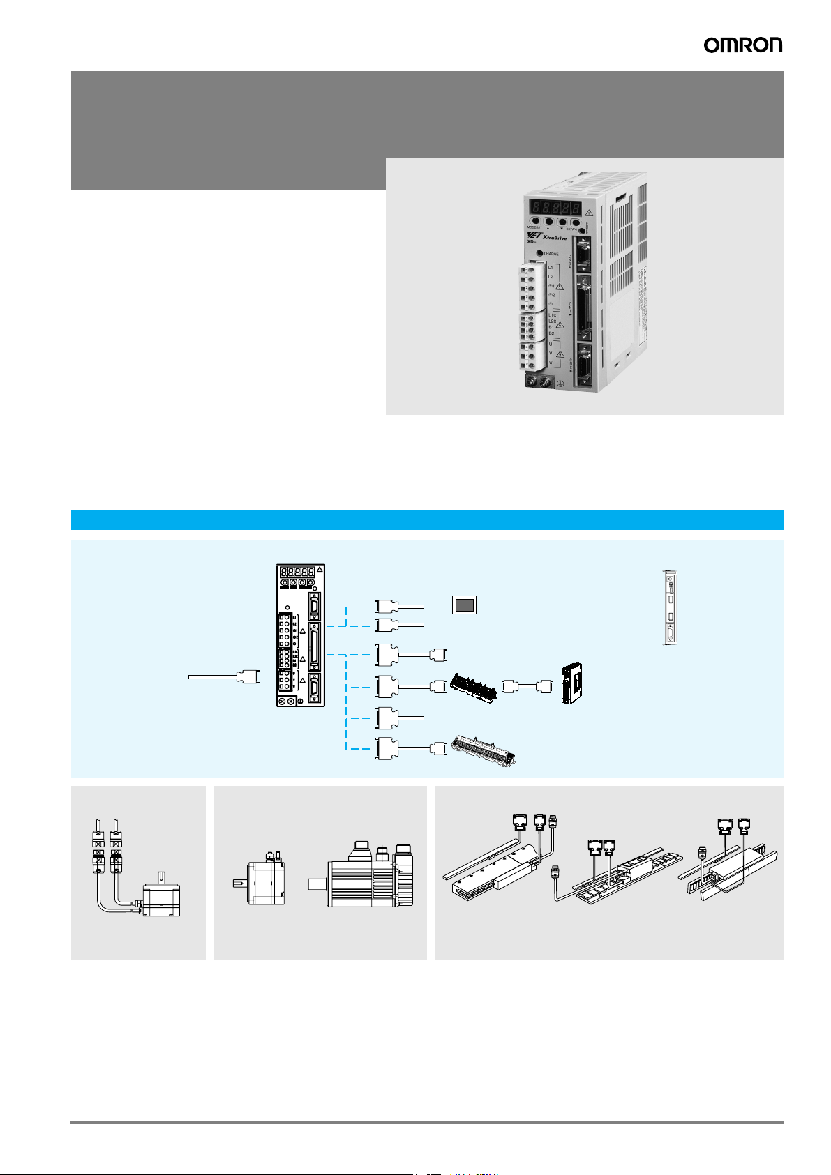
XD-@, XD-@-E
XtraDrive
Intelligent servo drive. Integrated controller
and network connectivity.
• NCT. Patented non-linear algorithm for tight control
• Very low tracking error with no overshoot and zero
settling time
• Supports different servo motor encoder types
• PROFIBUS embedded in the drive available
• XtraDive model available with electronic CAM
• The ideal drive for linear motor control
• Fast hardware registration input
• Intuitive text programming language
• Automatic tuning of servo parameters for optimal
settling time
• Oscilloscope available via XtraWare software tool
• CompoWay/F is supported, it allows remote access
to the drives through the PLC
Ratings
• 230 VAC single-phase 30 W to 1.5 kW (4.77 Nm)
• 400 VAC three-phase 0.5 kW to 5.0 kW (28.4 Nm)
System configuration
XtraDrive
Servo Drives
Filter
PROFIBUS network
(XtraDrive models with
embedded PROFIBUS)
(Refer to chapter
SmartStep servo motors)
Cables
R7M Servo Motor
(Refer to chapter
Sigma-II rotary motors)
CHARGE
SGMAH, SGMPH
Servo Motor
POWER
CN3
CN1
CN2
Analog monitor cable
Cables
SGMGH, SGMUH,
SGMSH, SGMBH
Servo Motor
Human machine interface
Personal computer
Motion control unit
Position control
unit
General purpose cable
Terminal block
(Refer to chapter Sigma-II linear motors)
SGLG_ linear
Servo Motor
SGLF_ linear
Servo Motor
Option unit
NS115
S
W
1
A
R
S
W
2
C
N
6
A
C
N
6
B
C
N
4
Cables
SGLT_ linear
Servo Motor
121XtraDrive
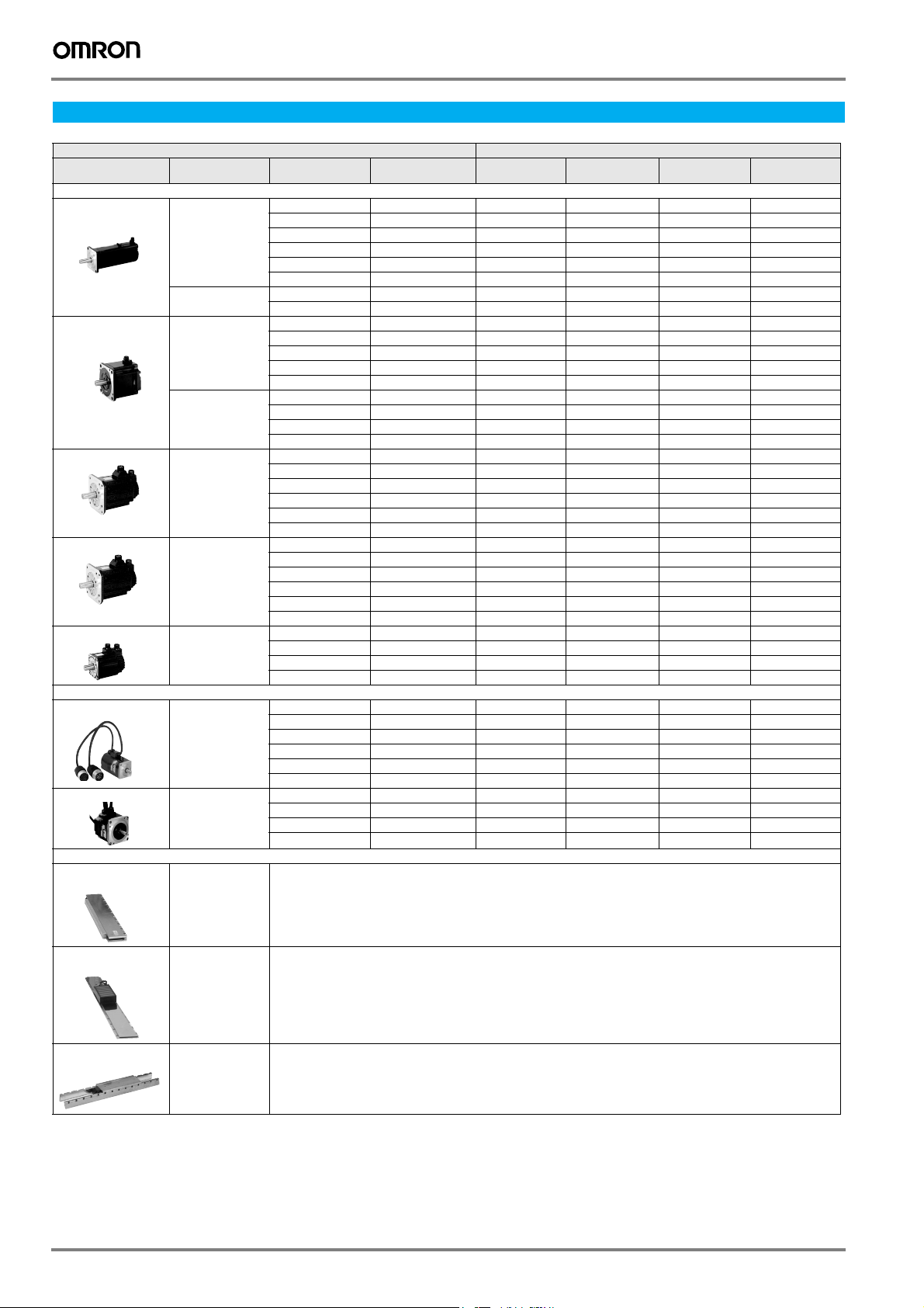
Servo motor / servo drive combination
Servo motor Servo drive
Voltage Rated torque Capacity 230 V (1-phase) 230 V (1-phase)
Sigma-II series motors (refer to the Sigma-II rotary motors chapter for details)
SGMAH (3000 min
SGMPH (3000 min
SGMGH (1500 min
SGMSH (3000 min
SGMUH (6000 min
SmartStep series motors (refer to the SmartStep servo motors chapter for details)
R7M-A (3000 min
R7M-AP (3000 min
Sigma linear motors (refer to the Sigma linear motors chapter for details)
SGLGW
Linear motors
-1
) 230 V 0.0955 N.m 30 W XD-P3-MN01-@ XD-P3-MSD0-@ --
0.159 N.m 50 W XD-P5-MN01-@ XD-P5-MSD0-@ --
0.318 N.m 100 W XD-01-MN01-@ XD-01-MSD0-@ --
0.637 N.m 200 W XD-02-MN01-@ XD-02-MSD0-@ --
1.27 N.m 400 W XD-04-MN01-@ XD-04-MSD0-@ --
2.39 N.m 750 W XD-08-MN@ XD-08-MSD0-@ --
400 V 0.955 N.m 300 W - - XD-05-TN@ XD-05-TSD0-@
-1
) 230 V 0.318 N.m 100 W XD-01-MN01-@ XD-01-MSD0-@ --
2.07 N.m 650 W - - XD-10-TN@ XD-10-TSD0-@
0.637 N.m 200 W XD-02-MN01-@ XD-02-MSD0-@ --
1.27 N.m 400 W XD-04-MN01-@ XD-04-MSD0-@ --
2.39 N.m 750 W XD-08-MN@-@ XD-08-MSD0-@ --
4.77 N.m 1500 W XD-15-MN@-@ ---
400 V 0.637 N.m 200 W - - XD-05-TN@ XD-05-TSD0-@
1.27 N.m 400 W - - XD-05-TN@ XD-05-TSD0-@
2.39 N.m 750 W - - XD-10-TN@ XD-10-TSD0-@
-1
) 400 V 2.84 N.m 0.45 kW - - XD-05-TN@ XD-05-TSD0-@
4.77 N.m 1500 W - - XD-15-TN@ XD-15-TSD0-@
5.39 N.m 0.85 kW - - XD-10-TN@ XD-10-TSD0-@
8.34 N.m 1.3 kW - - XD-15-TN@ XD-15-TSD0-@
11.5 N.m 1.8 kW - - XD-20-TN@ XD-20-TSD0-@
18.6 N.m 2.9 kW - - XD-30-TN@ XD-30-TSD0-@
-1
) 400 V 3.18 N.m 1.0 kW - - XD-10-TN@ XD-10-TSD0-@
28.4 N.m 4.4 kW - - XD-50-TN@ -
4.90 N.m 1.5 kW - - XD-15-TN@ XD-15-TSD0-@
6.36 N.m 2.0 kW - - XD-20-TN@ XD-20-TSD0-@
9.80 N.m 3.0 kW - - XD-30-TN@ XD-30-TSD0-@
12.6 N.m 4.0 kW - - XD-50-TN@ -
-1
) 400 V 1.59 N.m 1.0 kW - - XD-10-TN@ XD-10-TSD0-@
15.8 N.m 5.0 kW - - XD-50-TN@ -
2.45 N.m 1.5 kW - - XD-15-TN@ XD-15-TSD0-@
4.9 N.m 3.0 kW - - XD-30-TN@ XD-30-TSD0-@
6.3 N.m 4.0 kW - - XD-50-TN@ -
-1
) 230 V 0.0955 N.m 30 W XD-P3-MN01-@ ---
0.159 N.m 50 W XD-P5-MN01-@ ---
0.318 N.m 100 W XD-01-MN01-@ XD-01-MSD0-@ --
0.637 N.m 200 W XD-02-MN01-@ XD-02-MSD0-@ --
1.27 N.m 400 W XD-04-MN01-@ XD-04-MSD0-@ --
-1
) 230 V 0.318 N.m 100 W XD-01-MN01-@ XD-01-MSD0-@ --
2.39 N.m 750 W XD-08-MN@ XD-08-MSD0-@ --
0.637 N.m 200 W XD-02-MN01-@ XD-02-MSD0-@ --
1.27 N.m 400 W XD-04-MN01-@ XD-04-MSD0-@ --
2.39 N.m 750 W XD-08-MN@ XD-08-MSD0-@ --
230 V Refer to the linear motors chapter for details
w PROFIBUS
400 V (3-phase) 400 V (3-phase)
w PROFIBUS
SGLFW
Linear motors
SGLTW
230 V,
400 V
Refer to the linear motors chapter for details
400 V Refer to the linear motors chapter for details
Linear motors
122 AC servo systems
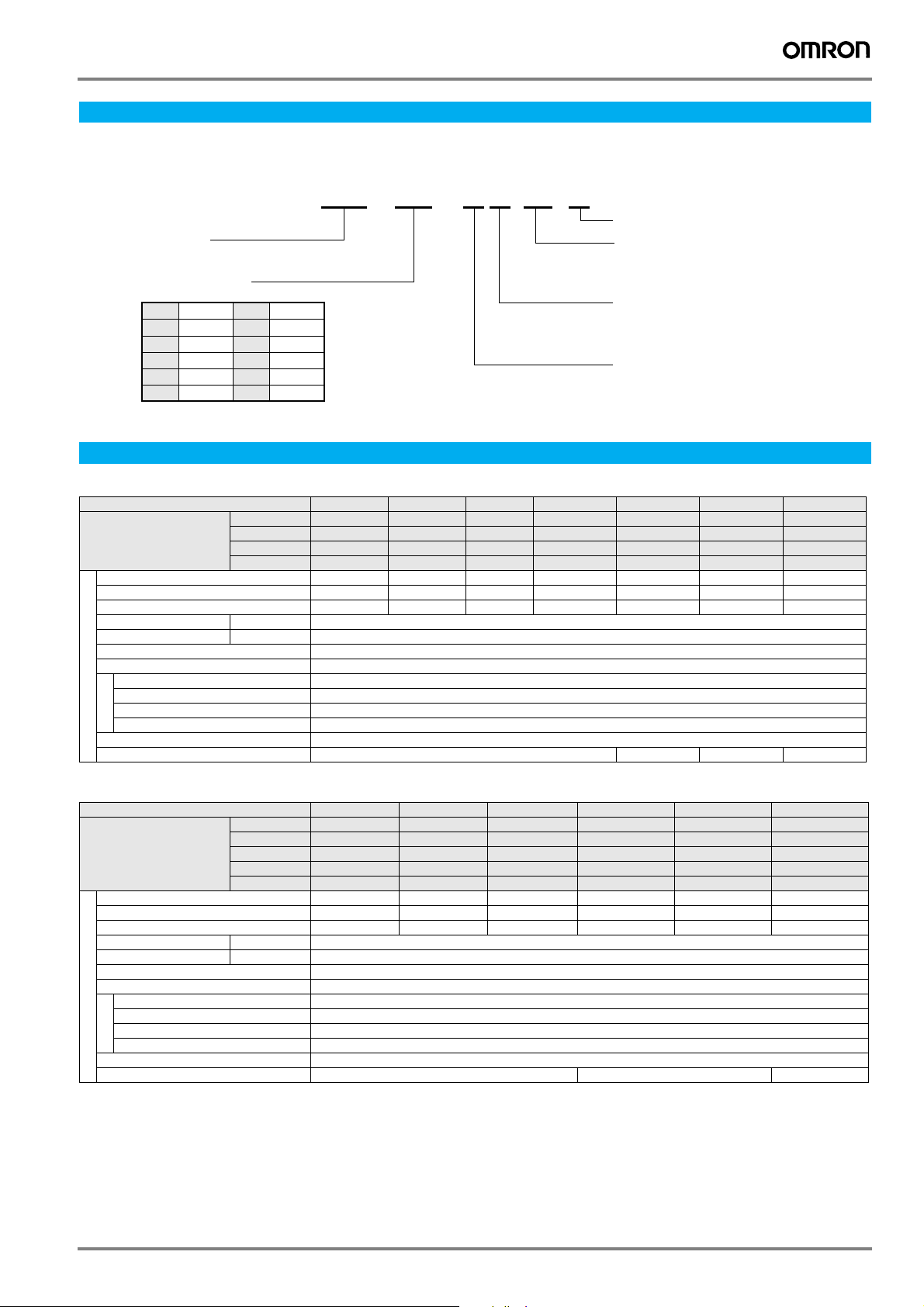
Type designation
Drive
XD - 01 - MN 01-E
Electronic CAM enabled
XtraDrive
Output capacity
P3 30 W
P5
50 W
01
100 W
02
200 W
04
400 W
500 W05
08
10
15
20
750 W
1.0 kW
1.5 kW
2.0 kW
3.0 kW30
5.0 kW50
Servo drive specifications
Single-phase, 230 V
Servo drive type XD-P3-M@ XD-P5-M@ XD-01-M@ XD-02-M@ XD-04-M@ XD-08-M@ XD-15-M@
Applicable
servo motor
Max. applicable motor capacity W 30 50 100 200 400 750 1500
Continuous output current Arms 0.44 0.64 0.91 2.1 2.8 5.7 11.6
Max. output current Arms 1.3 2.0 2.8 6.5 8.5 13.9 28
Input power Main circuit For single-phase, 200 to 230 VAC + 10 to -15%
Supply Control circuit For single-phase, 200 to 230 VAC + 10 to -15%
Control method Single phase full-wave rectification / IGBT / PWM / sine-wave current drive method
Feedback Serial encoder (incremental/absolute value)
Usage/storage temperature 0 to +55 °C / -20 to 85 °C
Usage/storage humidity 90%RH or less (non-condensing)
Basic specifications
Altitude 1000 m or less above sea level
Vibration/shock resistance 4.9 m/s
Conditions
Configuration Base mounted
Approx. weight Kg 0.8 1.1 1.7 3.8
SGMAH-@ A3A@ A5A@ 01A@ 02A@ 04A@ 08A@ 15A@
SGMPH-@ - - 01A@ 02A@ 04A@ 08A@ -
R7M-@ A03030-@ A05030-@ A10030-@ A20030-@ A40030-@ A75030-@ -
R7M-@ - - AP10030-@ AP20030-@ AP40030-@ AP75030-@ -
2
/ 19.6 m/s
2
Design version # (optional)
01: Design version
D0: Embedded PROFIBUS
Extended functionality
N: With CN10 connector for option units
S: No CN10 connector
Input voltage
M: 230 V
T: 400 V
Three-phase, 400 V
Servo drive type XD-05-T@ XD-10-T@ XD-15-T@ XD-20-T@ XD-30-T@ XD-50-T@
Applicable
servo motor
Max. applicable motor capacity kW 0.45 1.0 1.5 2.0 3.0 5.0
Continuous output current Arms 1.9 3.5 5.4 8.4 11.9 16.5
Max. output current Arms 5.5 8.5 14 20 28 40.5
Input power Main circuit For three-phase, 380 to 480 VAC + 10 to -15% (50/60 Hz)
Supply Control circuit 24 VDC+15%
Control method Three phase full-wave rectification / IGBT / PWM / sine-wave current drive method
Feedback Serial encoder (incremental/absolute value)
Usage/storage temperature 0 to +55 °C / -20 to +85 °C
Usage/storage humidity 90%RH or less (non condensing)
Basic specifications
Altitude 1000 m or less above sea level
Vibration/shock resistance 4.9 m/s
Conditions
Configuration Base mounted
Approx. weight Kg 2.8 3.8 5.5
SGMAH-@ 03D@ 07D@ - - - -
SGMPH-@ 02D@, 04D@ 08D@ 15D@ - - -
SGMGH-@ 05D@ 09D@ 13D@ 20D@ 30D@ 44D@
SGMSH-@ - 10D@ 15D@ 20D@ 30D@ 40D@/50D@
SGMUH-@ - 10D@ 15D@ - 30D@ 40D@
2
/ 19.6 m/s
2
XtraDrive 123

General specifications
Speed control range 1:5000
Speed
variance
Frequency characteristics 400Hz (at J
Torque control accuracy (reproducibility) ±2%
Performance
Soft start time setting 0 to 10s (acceleration, deceleration can each be set.)
Speed
reference
input
Torque
reference
input
Speed/torque control mode
Input signal
Contact
speed
reference
Bias Setting 0 to 450 min-1 (setting resolution: 1 min-1)
Feed forward compensation 0 to 100 % (setting resolution: 1%)
Position completed width setting 0 to 250 command units (setting resolution: 1 command unit)
Performance
Command
pulse
Position control mode
Control signal Clear signal (input pulse is same as reference pulse)
Input signal
Position signal output A-phase, B.phase, C-phase, (S-phase): line driver output S-phase is for absolute encoder only.
Sequence input signal Servo ON, P control (or control mode switching, zero clamp, command pulse inhibit), forward/reverse run
Sequence output signal Servo alarm, alarm codes (3-bit output): CN1 output terminal is fixed
I/O signal
Communications Interface Digital operator (hand- held type), RS-422 port for PCs, etc. (RS-232C ports under some conditions)
Auto tuning function Position speed loop gain and integral time constant can be automatically set.
Dynamic brake (DB) Operates during main power OFF, servo alarm, servo OFF or overtravel
Regenerative processing Regenerative resistor externally mounted (option)
Overtravel (OT) prevention function DB stop, deceleration stop or coast to stop during P-OT, N-OT operation
Encoder divider function Optional division possible
Electronic gearing 0,01< A/B<100
Internal speed setting function 3 speeds may be set internally
Integrated functions
Protective functions Overcurrent, overvoltage, insufficient voltage, overload, main circuit sensor error, heatsink overheat, power phase
Analog monitor functions for supervision Integrates analog monitor connectors for supervision of the speed and torque reference signals, etc.
Display functions CHARGE, POWER, 7-segments LEDx5
Others Reverse connection, zero search, automatic motor discrimination function, and DC reactor connection terminal
Load variance During 0 to 100% load ±0.01% max. (at rated speed)
Voltage variance Rated voltage ±10%: 0% (at rated speed)
Temperature variance 25 ±25 °C: ±0.1 % max (at rated speed)
Reference voltage ±6VDC (forward motor rotation if positive reference) at rated speed: Set at delivery
Input empedance Approx. 14 kΩ
Circuit time constant Reference voltage ±3 VDC (forward rotation if positive reference) at rated speed: Set at delivery
Imput impedance Approx. 14 KΩ
Circuit time constant Approx. 47 µs
Rotation direction selection With P control signal
Speed selection With forward/reverse current limit signal (speed 1 to 3 selection), servo motor stops or another control method is
Input pulse type Sign + pulse train, 90° phase displacement 2-phase pulse (A-phase+ B-phase) or CCW/CW pulse train
Input pulse form Line driver (+5 V level) , open collector (+5 V or +12 level)
Input pulse frequency 0 to 500 Kpps (200 Kpps max. at open collector)
1:N communications N may equal up to 14 when an RS-422A port is used.
Axis address setting Set by user setting
Functions Status display, user constant setting monitor display, alarm traceback display, JOG run /autotuning operations,
PROFIBUS (Only models with PROFIBUS) PROFIBUS DP slave, node address 0-125 set by rotary switches, baud rate from
Variable setting range: ±2 to ±10 VDC at rated speed/ max. input voltage: ±12 V
Variable setting range ±1 to ±10 VDC at rated torque reference
used when both are OFF.
prohibit, alarm reset, forward/ reverse current limit (or internal speed switching)
It is possible to output three types of signals form among: positioning complete (speed agree), motor rotation,
servo ready, current limit, speed limit, brake release, warning, NEAR, and zero point pulse signal
CompoWay/F protocol is supported on firmware version "3.20C" and higher
and graphing functions for speed/torque command signal, etc
9.6 kbps to 12 Mbps. LED Indicators: Bus failure and system failure
loss, overflow, overspeed, encoder error, runaway, CPU error, parameter error, etc.
(Integrated digital operator function, not available in models with PROFIBUS)
for high frequency power suppression function (except: 6 to 15 kW)
= JM)
L
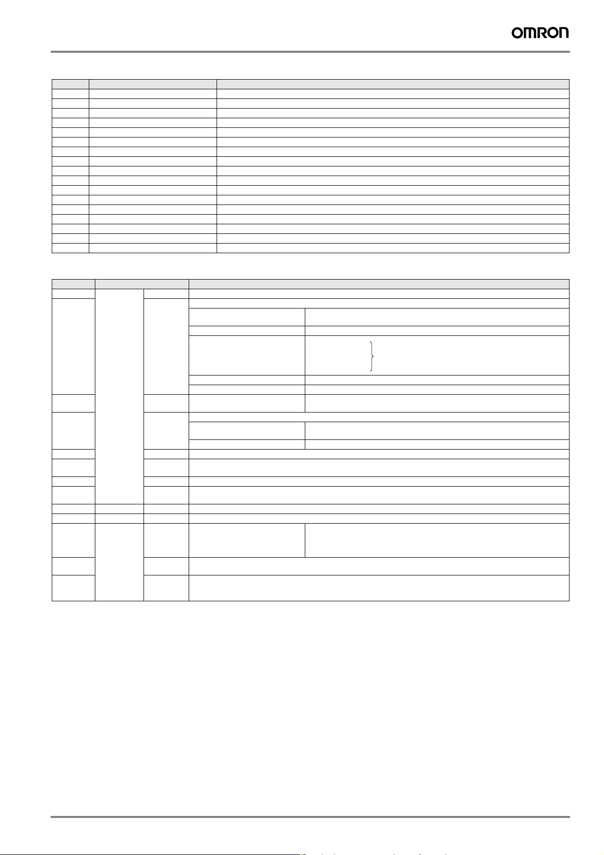
I/O specifications
Terminal specifications
Symbol Name Function
L1, L2 or
L1, L2, L3
U Servo motor connection terminal Red Terminals for outputs to the servo motor.
V White
WBlue
L1C, L2C Control power input terminal AC power input terminals for the control circuit.
B1, B2 or
B1, B2, B3
⊕1, ⊕2 DC reactor connection terminal for sup-
⊕ Main circuit DC output terminal (+) Normally, not connected.
Main circuit AC input terminal AC power input terminals for the main circuit
Frame ground Ground terminal. Ground to a maximum of 100 Ω. (class 3)
Main circuit DC output terminal 5 kW or less: Connect an external regenerative resistor if regenerative energy is high.
pressing power supply harmonic waves
Main circuit DC output terminal (n-) Normally, not connected.
5.5 kW: There is no internal regenerative resistor. Be sure to connect an external regenerative resistor unit.
Normally, short ⊕1 and ⊕2. If a countermeasure against power supply harmonic waves is needed,
connect a DC reactor between ⊕1 and ⊕2.
This terminal exists on the servo drives with a capacity opf 6.0 kW or higher only.
124 AC servo systems
Encoder connector (CN2)
Pin Symbol Function
1, 2, 3 PPG0V Encoder power supply GND
4, 5, 6 PPG5V Encoder power supply +5 V
7- 8 PS+ Encoder serial signal input
9PS− Encoder serial signal input
10 SePG5V Serial encoder power supply +5 V (Sigma-II)
11 SePG0V Serial encoder power supply GND (Sigma-II)
12 BAT+ Battery + (used only with absolute encoder)
13 BAT- Battery - (used only with absolute encoder)
14 PC+ Encoder + C-phase input
15 PC− Encoder − C-phase input
16 A+ Encoder + A-phase input
17 A− Encoder − A-phase input
18 B+ Encoder + B-phase input
19 B− Encoder − B-phase input
20 - Shell FG Cable shield ground
I/O signals (CN1) - input signals
Pin No. Signal Name Function
40 Common /S-ON Servo ON: Turns ON the servo motor when the gate block in the inverter is released.
41 /P-CON Function selected by parameter.
42
43
45
46
44 /ALM-RST Alarm reset: releases the servo alarm state.
47 +24VIN Control power supply input for sequence signals: users must provide the +24 V power supply.
4 (2) SEN Initial data request signal when using an absolute encoder.
21
22
5 (6) Speed V-REF Speed reference speed input: ±2 to ±10 V/rated motor speed (input gain can be modified using a parameter.)
9 (10) Torque T-REF Torque reference input: ±1 to ±10 V/rated motor torque (input gain can be modified using a parameter.)
7
8
11
12
15
14
3
13
18
Position PULS
P-OT
N-OT
/P-CL
/N-CL
BAT (+)
BAT (-)
/PULS
SIGN
/SIGN
CLR
/CLR
PL1
PL2
PL3
Proportional control reference Switches the speed control loop from PI (proportional/ integral) to P (proportional)
Direction reference With the internal set speed selected: switch the rotation direction.
Control mode
switching
Zero-clamp reference Speed control with zero-clamp function: referencevspeed is zero when ON.
Reference pulse block Position control with reference pulse stop: stops reference pulse input when ON.
Forward run prohibited
Reverse run prohibited
Function selected by parameter.
Forward external torque limit ON
Reverse external torque limit ON
Internal speed switching With the internal set speed selected: switches the internal speed settings.
Allowable voltage fluctuation range: 11 to 25 V
Connecting pin for the absolute encoder backup battery.
Do not connect when a battery is connected to the host controller.
Reference pulse input
for line driver only
Positional error pulse clear input: clears the positional error pulse during position control.
+12 V pull-up power is supplied when PULS, SIGN, and CLR reference signals are open-collector outputs
(+12 V power supply is built into the SERVOPACK).
control when ON.
↔
Position speed
↔
Position
Torque speed
Overtravel prohibited: stops servo motor when movable part travels beyond the
allowable range of motion.
Current limit function enabled when ON.
Input mode is set from the following pulses.
Sign + pulse string
CCW/CW pulse
Two-phase pulse (90° phase differential)
torque
↔
Enables control mode switching.
Note: 1. Pin numbers in parentheses () indicate signal grounds.
2. The functions allocated to /S-ON, /P-CON. P-OT, N-OT, /ALM-RST, /P-CL, and /N-CL input signals can be changed by using the
parameters.
3. The voltage input range for speed and torque references is a maximum of ±12 V.
XtraDrive 125

I/O signals (CN1) - output signals
Pin No. Signal name Function
31
32
27
28
29
30
33 (1)
34
35
36
19
20
48
49
37
38
39 (1)
16 TMON Analog monitor signal
17 VTG Analog monitor signal
Shell FG Connected to frame ground if the shield wire of the I/O signal cable is connected to the connector shell.
25
26
25
26
- Reserved /CLT
23
24
50
Common ALM+
Speed /V-CMP+
Position /COIN+
ALM/TGON+
/TGON/S-RDY+
/S-RDY PAO
/PAO
PBO
/PBO
PCO
/PCO
PSO
/PSO
ALO1
ALO2
ALO3
/V-CMP-
/COIN-
/VLT
/BK
/WARN
/NEAR
- Terminals not used
Servo alarm: Turns OFF when an error is detected.
Detection during servo motor rotation: detects when the servo motor is rotating at a speed higher than
the motor speed setting. Detection speed can be set by using the parameters.
Servo ready: ON if there is no servo alarm when the control/main circuit power supply is turned ON.
Phase-A signal Converted two-phase pulse (phases A and B) encoder output signal and
Phase-B signal
Phase-C signal
Phase-S signal With an absolute encoder: Outputs serial data corresponding to the number of revolutions
Alarm code output:Outputs 3-bit alarm codes.
Open-collector: 30 V and 20 mA rating maximum
Speed coincidence (output in speed control mode): Detects whether the motor speed is within the setting range and if
it matches the reference speed value.
Positioning completed (output in position control mode): Turns ON when the number of positional error pulses
reaches the value set. The setting is the number of positional error pulses set in reference units
(input pulse units defined by the electronic gear).
Reserved terminals
The functions allocated to /TGON, /S-RDY, and /V-CMP (/COIN) can be changed by using the parameters. /CLT, /VLT,
/BK, /WARN, and /NEAR signals can also be changed.
Do not connect relays to these terminals.
zero-point pulse (phase C) signal: RS-422 or the equivalent
(proper line receiver is SN75175 manufactured by Texas Instruments or the equivalent
corresponding to MC3486.)
(RS-422 or the equivalent)
Note: 1. Pin numbers in parentheses () indicate signal grounds.
2. The functions allocated to /TGON, /S-RDY, and /V-CMP (/COIN) can be changed by using the parameters. /CLT, /VLT, /BK, /WARN, and
/NEAR signals can also be changed.
126 AC servo systems

Dimensions
Servo drives
XD-P3-M@ to XD-02-M@ (230V, 30 to 200W)
Terminal
block
160
6
CN3
CHARGE
CN1
CN2
Mounting hole diagram
2×M4 screw holes
5.5
CN10
POWER
CN3
39
CN1
160
106
CN2
149.5±0.5
(Mounting pitch)
Ground terminal
2×M4 screws
XD-04-M@ (230V, 400W)
Ground terminal
2×M4 screws
XD-08-M@ (230V, 750W)
96.2
Cooling fan
160
5.5
Terminal
block
149.5
6
(5)
12
6
2×φ5 holes
94.4
55
CHARGE
5
63
75
Terminal
block
160
5
15
10
8
75
130
5
5
55
Mounting hole diagram
2×M4 screw holes
5.5
CN10
POWER
CN3
CN1
CN2
10
39
106
6
CN3
CN1
CN2
75
130
160
149.5±0.5
5
(Mounting pitch)
12
75
8
φ5 hole
CHARGE
Ground terminal
2×M4 screws
10
35
55
90
CN10
POWER
CN3
CN1
39
CN3
CN1
106
CN2
CN2
75
180
8
Mounting hole diagram
5.5
2×M4 screw
holes
160
149.5±0.5
(Mounting pitch)
27
5
90
XtraDrive 127

XD-05-T@ to -15-T@ (400V, 0.5 to 1.5kW)
2×φ5 holes
Heat sink
CN3
CHARGE
160
CN1
-
CN2
Ground
terminal
5
2×M4 screws
110
XD-15-M@ (230V, 1.5kW)
XD-20-T@, XD-30-T@ (400V, 2/3kW)
2×φ6 holes
6
POWER
Heat sink
CN3
39
CN1
106
CN2
Terminal
block
8
CHARGE POWER
CN3
39
CN10
75
CN3
CN10
180
Mounting hole diagram
5.5
160
149.5±0.5
(Mounting pitch)
5
5
4
Mounting hole diagram
6
4×M4 screw holes
100±0.5
(Mounting pitch)
110
4×M5 tap
5
14-pin terminal
M4 mounting
screw
Ground terminal
2×M4 screws
XD-50-T@ (400V, 5kW)
Heat sink 6-pin terminal
6
250
238.5
L1
L2
L3
+
+
-
250
1
2
238.5
5.5
5
M5 screw
L1C
L2C
B1
B2
B3
U
V
W
6
100
110
Name plate
CHARGE POWER
CN1
CN1
CN2
CN2
196
5
8
8
4-pin terminal
M4 screw
CN10
CN3
CN1
CN2
238.5±0.5
250
(Mounting pitch)
100±0.5
5
5.5
75
180
4
(Mounting pitch)
110
5
Mounting hole diagram
6
4´M5 screw taps
250
238.5±0.5
(Mounting pitch)
5.7
5
5.5
Ground terminal
M5 screw
125
135
5
3-pin terminal
M5 screw
75
230
1.6
55
5.5
125±0.5
(Mounting pitch)
128 AC servo systems

Filters
R88A-FIW104-SE
Units:mm (in)
1
(0.20)
(0.04)
11.5(0.45)
33(1.30)
15(0.59)
28.25(1.11)
56(2.20)
(φ0.20)
5.5(0.22)
14(0.55)
19(0.75)
32(1.26)
M4
φ5
φ10(φ0.39)
70(2.76)
+0.20
0
+5
0
240 (9.45 )
202(7.95)
192(7.56)
149.5(5.89)
wires AWG16
168(6.61)
GNYE
5
M4(2
×
)
+0.20
0
6(0.24)
+5
0
M4
265 (10.43 )
R88A-FIW107-SE, R88A-FIW115-SE
Model R88A-FIW107-SE R88A-FIW115-SE
Dimensions
in mm
A 75 90
B 240
+5
300+5
C 50 60
D 12 15
E1 1.2
Units:mm
A
32
16
202
192
15028
M4
φ5
φ10
5.5
14
19
B
70
168
wires AWG16
GNYE
M4
M4(2×)
+5
E
D
5
C
0
265
15
R88A-FIW125-SE
Units:mm(in)
R88A-FIW4006-SE, R88A-FIW4010-SE
Model R88A-FIW4006-SE R88A-FIW4010-SE
Dimensions
in mm (in)
A 32 (1.26) 35 (1.38)
B 16 (0.63) 18 (0.71)
C 202 (7.95) 291 (11.46)
D 192 (7.56) 281 (11.06)
E 150 (5.91) 239 (9.41)
F 300 (11.81) 270 (10.63)
G 70 (2.76) 90 (3.54)
H 168 (6.61) 257 (10.12)
Units:mm(in)
A
B
1.2
C
D
28(1.10)
L1 L2 L3
M4
118(4.65)
φ10(φ0.39)
φ5
(φ0.20)
5.5(0.22)
14(0.55)
19(0.75) H 15(0.59)
F
G
E
wires AWG16
GNYE
M4
+0.20
0
+5
0
310 (12.20 )
M4(4
5(0.20)
×
)
(0.05)
19(0.75)80(3.15)
10(0.39)
100(3.94)
R88A-FIW4020-SE
Units:mm(in)
40(1.57)
140(5.51)
114(4.49)
20
(0.79)
7.5(0.30)
φ10
(φ0.39)
M5
φ5.5
(φ0.22)
M5
125(4.92)
302(11.89)
285(11.22)
8.5(0.33)
5.5(0.22)
35(1.38)
18
(0.71)
28(1.10)
M5
118(4.65)
5.5(0.22)
φ10(φ0.39)
φ5
(φ0.20)
+0.02
14(0.55)
19(0.75) 257(10.12) 15(0.59)
0
+0.5
0
245 (9.65 )
90(3.54)
M4
291(11.46)
281(11.06)
239(9.41)
wires AWG16
GNYE
M4
+0.02
0
+5
0
355 (13.98 )
M4(4
5(0.20)
×
)
1.2
(0.05)
10(0.39)
19(0.75)80(3.15)
100(3.94)
AWG 14
0
+5
0
350 (13.78 )
gb/gr
M5
+0.20
0
+5
0
580 (22.83 )
238.5(9.39)
253(9.96)24.5(0.96)
AWG 2 0
+0.20
0
+5
0
370 (14.57 )
24.5(0.96)
+0.20
XtraDrive 129

Installation
Single-phase, 230 VAC
Single-phase 200 to 230 VAC
Noise filter
Powe r
Off
Powe r
ON
Alarm processing
4
Be sure to attach a surge suppressor to the excitation
coil of the magnetic contactor and relay
Servo motor
Speed reference
(±2 to ±10 V/rated motor speed)
Torque reference
(
±
1 to ±10 V/rated torque)
Position reference
Open-collector
reference
Power supply
Backup battery
(2.8 to 4.5 V)
SEN signal input
Servo ON
(Servo ON when ON)
P control
(P control when ON)
Forward run prohibited
(Prohibited when OFF)
Reverse run prohibited
(Prohibited when OFF)
Alarm reset
(Reset when ON)
Forward current limit
(Limit when ON)
Reverse current limit
(Limit when ON)
∗2
∗2
Be sure to
ground
1
1
XtraDrive
Connect shield to
connector shell.
Optical encoder
Be sure to prepare the end of
the shielded wire properly
Alarm code output
Max. operating voltage:
30 VDC
Max. operating current:
20 mA DC
PG dividing ratio output
Applicable line receiver
SN75175 manufactured
by Texas Instruments or
the equivalent corresponding
to MC3486
3
Amount of phase-S rotation
Serial data output
Applicable line receiver
SN75175 manufactured
by Texas Instruments or
the equivalent corresponding
to MC3486
Speed coincidence detection
(ON when speed coincides.)
Running output
(ON when the motor speed
exceeds the settings.)
Servo ready output
(ON when ready)
Servo alarm output
(OFF for an alarm)
Photocoupler output
Max. operating voltage:
30 VDC
Max. operating current:
50 mA DC
*1 The time constant for the primary filter is 47 µs.
*2 Connect when using an absolute encoder.
*3 Used only with an absolute encoder.
*4 Regenerative resistor can be connected between B1 and B2.
*6 TI stands for Texas Instruments Inc.
130 AC servo systems

Three-phase, 400 VAC
Three-Phase 380 to 480 VAC
L1 L2 L3
Noise filter
Powe r
Off
Powe r
ON
Alarm processing
4
Be sure to attach a surge suppressor to the excitation
coil of the magnetic contactor and relay
Servo motor
Power Supply
Speed reference
(±
2 to ±10 V/rated motor speed)
Torque reference
(
±
1 to ±10 V/rated torque)
Position reference
Backup battery
(2.8 to 4.5 V)
SEN signal input
*5
∗
2
∗2
Open-collector
reference
Power supply
Be sure to
ground
XtraDrive
1
1
3
Be sure to prepare the end of
the shielded wire properly
Optical encoder
Alarm code output
Max. operating voltage:
30 VDC
Max. operating current:
20 mA DC
PG dividing ratio output
Applicable line receiver
SN75175 manufactured
by Texas Instruments or
the equivalent corresponding
to MC3486
Amount of phase-S rotation
Serial data output
Applicable line receiver
SN75175 manufactured
by Texas Instruments or
the equivalent corresponding
to MC3486
Servo ON
(Servo ON when ON)
P control
(P control when ON)
Forward run prohibited
(Prohibited when OFF)
Reverse run prohibited
(Prohibited when OFF)
Alarm reset
(Reset when ON)
Forward current limit
(Limit when ON)
Reverse current limit
(Limit when ON)
Connect shield to
connector shell.
*1 The time constant for the primary filter is 47 µs.
*2 Connect when using an absolute encoder.
*3 Used only with an absolute encoder.
*4 For using an external regenerative resistor, connect it between B1 and B2.
*5 The 24VDC power is supplyed by the user.
*6 TI stands for Texas Instruments Inc.
Speed coincidence detection
(ON when speed coincides.)
Running output
(ON when the motor speed
exceeds the settings.)
Servo ready output
(ON when ready)
Servo alarm output
(OFF for an alarm)
Photocoupler output
Max. operating voltage:
30 VDC
Max. operating current:
50 mA DC
XtraDrive 131

Ordering information
Analog monitor cable
J
Cables
L
K
D
F
H
General purpose cable
I
Human machine interface
Personal computer
Motion control unit
E
G
Terminal block
(Refer to chapter Sigma-II linear motors)
SGLG_ linear
Servo Motor
A A
SGLF_ linear
Servo Motor
M
Option unit
Position control
unit
PROFIBUS network
(XtraDrive models with
embedded PROFIBUS)
(Refer to chapter
SmartStep servo motors)
B
Cables
R7M Servo Motor
A
C
XtraDrive
Servo Drives
Filter
(Refer to chapter
Sigma-II rotary motors)
SGMAH, SGMPH
Servo Motor
POWER
CN3
CHARGE
CN1
CN2
B
A A
SGMGH, SGMUH,
SGMSH, SGMBH
Servo Motor
Note: The symbols ABCDE... show the recommended sequence to select the components for a servo system
B
NS115
S
W
1
A
R
S
W
2
C
N
6
A
C
N
6
B
C
N
4
Cables
A
SGLT_ linear
Servo Motor
Servo motors, power & encoder cables
Note: AB Refer to the servo motors chapter for detailed motor specifications and selection
Servo Drives
Symol Specifications XtraDrive XtraDrive-E
C 1 phase
200 VAC
30 W XD-P3-MN01 XD-P3-MN01-E XD-P3-MSD0 XD-P3-MSD0-E SGMAH-A3A@ R7M-A03030-@ -
50 W XD-P5-MN01 XD-P5-MN01-E XD-P5-MSD0 XD-P5-MSD0-E SGMAH-A5D@ R7M-A05030-@ SGLGW-30A050@
with
electronic CAM
100 W XD-01-MN01 XD-01-MN01-E XD-01-MSD0 XD-01-MSD0-E SGMAH-01A@,
200 W XD-02-MN01 XD-02-MN01-E XD-02-MSD0 XD-02-MSD0-E SGMAH-02A@,
400 W XD-04-MN01 XD-04-MN01-E XD-04-MSD0 XD-04-MSD0-E SGMAH-04A@,
750 W XD-08-MN XD-08-MN00-E XD-08-MSD0 XD-08-MSD0-E SGMAH-08A@,
1.5 kW XD-15-MN XD-15-MN00-E - - SGMPH-15A@ - SGLFW-50A380@,
3 Phase
400 VAC
0.5 kW XD-05-TN XD-05-TN00-E XD-05-TSD0 XD-05-TSD0-E SGMGH-05D@,
1.0 kW XD-10-TN XD-10-TN00-E XD-10-TSD0 XD-10-TSD0-E SGMGH-09D@,
1.5 kW XD-15-TN XD-15-TN00-E XD-15-TSD0 XD-15-TSD0-E SGMGH-13D@,
2.0 kW XD-20-TN XD-20-TN00-E XD-20-TSD0 XD-20-TSD0-E SGMGH-20D@,
3.0 kW XD-30-TN XD-30-TN00-E XD-30-TSD0 XD-30-TSD0-E SGMGH-30D@,
5.0 kW XD-50-TN XD-50-TN00-E - - SGMGH-44D@,
Note: SGLGW-@ linear motor combination is made considering the use of standard magnets. Refer to the linear motors chapter for details
XtraDrive-DP
with
PROFIBUS
XtraDrive-DP-E
with PROFIBUS
and electronic
CAM
Compatible servo motors A
Sigma-II rotary SmartStep Sigma linear motors
SGMPH-01A@
SGMPH-02A@
SGMPH-04A@
SGMPH-08A@
SGMAH-03D@,
SGMPH-02D@/04D@
SGMSH/UH-10D@,
SGMAH-07D@,
R7M-A10030-@,
R7M-AP10030-@
R7M-A20030-@,
R7M-AP20030-@
R7M-A40030-@,
R7M-AP40030-@
R7M-A75030-@,
R7M-AP75030-@
-SGLFW-35D@
- SGLFW-50D200@,
SGLGW-30A080@,
SGLGW-40A140@
SGLFW-20A@,
SGLFW-35A120@,
SGLGW-40A253A@,
SGLGW-60A140@
SGLGW-40A365A@,
SGLGW-60A253A@
SGLFW-35A230@,
SGLFW-50A200@,
SGLGW-60A365A@
SGLFW-1ZA200@,
SGLGW-90A200A@
SGLTW-35D170@,
SGLTW-50D170
SGMPH-08D@
SGMSH/UH-15D@,
- SGLFW-50D380@,
SGLFW-1ZD200@
SGMPH-15D@
SGMSH-20D@
- SGLFW-1ED380@,
SGLTW-35D320@,
SGLTW-50D320@
SGMSH/UH-30D@
-SGLFW-1ZD380@,
SGLFW-1ED560@,
SGLTW-40D400@
SGMSH/UH-40D@,
- SGLTW-40D600@,
SGLTW-80D400@
SGMSH-50D@
@
132 AC servo systems

Control cables (for CN1)
Symbol Description Connect to Len Model
Control cable
D
(1 axis)
Control cable
(2 axis)
Terminal block
(4 axes)
Servo drive
connecting
cable (1 axis)
PLC unit control
cables (4 axes)
Servo relay unit CS1W-NC1@3,
E
Cable to servo
F
drive
Position control
G
unit connecting
cable
Control cable For general purpose
H
Relay terminal
I
block cable
Relay terminal
block
Motion control units
CS1W-MC221
CS1W-MC421
C200H-MC221
Motion control units
CS1W-MC221
CS1W-MC421
C200H-MC221
Motion control unit
C200HW-MC402-E
CJ1W-NC1@3, or
C200HW-NC113
Position control unit
CS1W-NC2@3/4@3,
CJ1W-NC2@3/4@3,
or C200HW-NC213/
413
Position control unit
CQM1H-PLB21
CQM1-CPU43
CJ1M-CPU22/23 XW2B-20J6-8A
Servo relay units
XW2B-@0J6-@B
C200H-NC112 0.5 m XW2Z-050J-A1
C200H-NC211 0.5 m XW2Z-050J-A2
CQM1-CPU43-V1 and
CQM1H-PLB21
CS1W-NC113 and
C200HW-NC113
CS1W-NC213/413
and
C200HW-NC213/413
CS1W-NC133 0.5 m XW2Z-050J-A10
CS1W-NC233/433 0.5 m XW2Z-050J-A11
CJ1W-NC113 0.5 m XW2Z-050J-A14
CJ1W-NC213/413 0.5 m XW2Z-050J-A15
CJ1W-NC133 0.5 m XW2Z-050J-A18
CJ1W-NC233/433 0.5 m XW2Z-050J-A19
CJ1M-CPU22/23 0.5 m XW2Z-050J-A27
controllers
General purpose
controller
1 m R88A-CPW001M1
2 m R88A-CPW002M1
3 m R88A-CPW003M1
5 m R88A-CPW005M1
1 m R88A-CPW001M2
2 m R88A-CPW002M2
3 m R88A-CPW003M2
5 m R88A-CPW005M2
- R88A-TC04-E
1 m R88A-CMUK001J3-
E2
1 m R88A-CMX001S-E
1 m R88A-CMX001J1-E
XW2B-20J6-1B
(1 axis)
XW2B-40J6-2B
(2 axes)
XW2B-20J6-3B
(1 axis)
(1 axis)
XW2B-40J6-9A
(2 axes)
1 m XW2Z-100J-B4
2 m XW2Z-200J-B4
1 m XW2Z-100J-A1
1 m XW2Z-100J-A2
0.5 m XW2Z-050J-A3
1 m XW2Z-100J-A3
0.5 m XW2Z-050J-A6
1 m XW2Z-100J-A6
0.5 m XW2Z-050J-A7
1 m XW2Z-100J-A7
1 m XW2Z-100J-A10
1 m XW2Z-100J-A11
1 m XW2Z-100J-A14
1 m XW2Z-100J-A15
1 m XW2Z-100J-A18
1 m XW2Z-100J-A19
1 m XW2Z-100J-A27
1 m R88A-CPW001S
or JZSP-CKI01-1
2 m R88A-CPW002S
or JZSP-CKI01-2
1 m R88A-CTW001N
2 m R88A-CTW002N
- XW2B-50G5
Cable (for CN5)
Symbol Name Model
J
Analog monitor cable R88A-CMW001S
or DE9404559
Options (for CN3)
Symbol Name Model
K
Computer connecting cable R88A-CCW002P2
or JZSP-CMS02
Human machine interface
Symbol Name Model
L
4.1“ HMI monochrome NT3S-ST126B-E
Option units (for CN10)
Symbol Name Model
M
IO card, 8 inputs / 8 outputs XDIO-08
Filters
Symbol Applicable servo drive Filter model Rated
N XD-P3-M@, XD-P5-M@,
XD-01-M@, XD-02-M@
XD-04-M@ R88A-FIW107-SE 7A
XD-08-M@ R88A-FIW115-SE 15 A
XD-15-M@ R88A-FIW125-SE 25 A
XD-05-T@, XD-10-T@,
XD-15-T@
XD-20-T@, XD-30-T@ R88A-FIW4010-SE 10 A
XD-50-T@ R88A-FIW4020-SE 20 A
R88A-FIW104-SE 4 A 250 VAC
R88A-FIW4006-SE 6 A 400 VAC
current
Rated
voltage
singlephase
threephase
Battery backup for absolute encoder
Name Model
Battery
(required for servo motors with absolute encoder)
JZSP-BA01
ER6VC3 (3.6V)
Connectors
Specification Model
Control I/O connector (for CN1) R88A-CNU11C
XtraDrive 200 V connector kit
(for 200 V motors
SGMAH/PH-@@A@@@D-OY
and R7M-A@-D)
XtraDrive 400 V connector kit.
(for 400 V motors
SGMAH/PH-@@D@@@D-OY)
Sigma-II drive encoder connector (For CN2) DE9406973
Hypertac encoder connector IP67
(for motors SGMAH/PH-@@@@@@@D-OY and
R7M-A@-D)
Hypertac power connector IP67, 200 V.
(for 200 V motors SGMAH/PH-@@A@@@@D-OY and
R7M-A@-D)
Hypertac power connector IP67, 400 V.
(for 400 V Motors SGMAH/PH-@@D@@@@D-OY)
Military encoder connector IP67
(for Motors SGMGH-@, SGMSH-@, SGMUH-@)
Military power connector IP67
(for 400 V motors SGMGH-(05/10/13)D@,
SGMSH-(10/15/20)D@ , SGMUH-(10/15)D@)
Military power connector IP67
(for 400 V motors SGMGH-(20/30/44)D@,
SGMSH-(30/40/50)D@, SGMUH-(30/40)D@)
Military brake connector IP67 (for 400 V servo motors
SGMGH-@, SGMSH-@, SGMUH-@)
Connectors included XD-CN200K-DE
DE9406973
SPOC-17H-FRON169
SPOC-06K-FSDN169
Connectors included XD-CN400K-DE
DE9406973
SPOC-17H-FRON169
LPRA-06B-FRBN170
or JZSP-CKI9
or R88A-CNU01R
SPOC-17H-FRON169
SPOC-06K-FSDN169
LPRA-06B-FRBN170
MS3108E20-29S
MS3108E18-10S
MS3108E22-22S
MS3108E10SL-3S
Computer software
Specifications Model
XtraWare MOTION TOOLS
XtraDrive 133

ALL DIMENSIONS SHOWN ARE IN MILLIMETERS.
To convert millimeters into inches, multiply by 0.03937. To convert grams into ounces, multiply by 0.03527.
Cat. No. I18E-EN-02
In the interest of product improvement, specifications are subject to change without notice.
134 AC servo systems
 Loading...