

Page 1

AC Servo Driver
Manual No.
8U0108-E1-01
Page 2

Copyright 2003 by YET, Yaskawa Eshed Technology Ltd.
XtraDrive User Manual
Catalog No.8U0108, Revision C
November 2003
All rights reserved. No part of this publication may be stored in a retrieval
system, or reproduced in any way, including but not limited to photocopy,
photography, magnetic or other recording, without the prior agreement and
written permission of the publisher. Program listings may be entered, stored and
executed in a computer system, but not reproduced for publication.
This guide is designed to provide information about the XtraDrive hardware.
Every effort has been made to make this guide complete and as accurate as
possible. However, no warranty of suitability, purpose or fitness is made or
implied. YET Ltd. is not liable or responsible to any person or entity for loss or
damage in connection with or stemming from the use of XtraDrive and/or the
information contained in this publication
YET Ltd. bears no responsibility for errors, which may appear in this
publication and retains the right to make changes to the products and the guide
without prior notice.
YET Ltd. ISRAEL YET US Inc.
13 Hamelacha St., 531 King St.,
Afeq Industrial Estate Unit 1
Rosh Ha’ayin 48091 Littleton, MA 01460
ISRAEL USA
Tel: +972-3-9004114 Tel: +1-866-YET-8080
Fax: +972-3-9030412 Fax: +1-978-952-6821
info@yetmotion.com USinfo@yetmotion.com
web site:
www.yetmotion.com
ii
Page 3

WARNING
YET manufactures component parts that can be used in a wide variety of industrial applications.
The selection and application of YET products remain the responsibility of the equipment designer
or end user. YET accepts no responsibility for the way its products are incorporated into the final
system design.
Under no circumstances should any YET product be incorporated into any product or design as the
exclusive or sole safety control. Without exception, all controls should be designed to detect faults
dynamically and fail safely under all circumstances. All products designed to incorporate a
component part manufactured by YET must be supplied to the end user with appropriate warnings
and instructions as to that part’s safe use and operation. Any warnings provided by YET must be
promptly provided to the end user.
YET offers an express warranty only as to the quality of its products in conforming to standards and
specifications published in YET’s manual. NO OTHER WARRANTY, EXPRESS OR IMPLIED,
IS OFFERED. YET assumes no liability for any personal injury, property damage, losses, or claims
arising from misapplication of its products.
iii
Page 4

This page intentionally left blank.
iv
Page 5
Safety Information
The following defines the symbols used in this manual to indicate varying
degrees of safety precautions and to identify the corresponding level of hazard
inherent to each. Failure to follow precautions provided in this manual can
result in serious, possibly even fatal, injury, and/or damage to the persons,
products, or related equipment and systems.
WARNING
• WARNING: Indicates a potentially hazardous situation, which, if not heeded, could result in
death or serious injury.
CAUTION
• CAUTION: Indicates a potentially hazardous situation, which, if not avoided, may result in
minor or moderate injury.
v
Page 6

This page intentionally left blank.
vi
Page 7

XtraDrive User Manual Table of Contents/Preface
Table of Contents
1. Checking Product and Part Names .................................................................1-1
1.1. Checking the XtraDrive Series Products on Delivery................................... 1-2
1.1.1. Servo Amplifiers....................................................................................... 1-2
1.2. Product Part Names ........................................................................................ 1-3
1.2.1. Servo Amplifiers....................................................................................... 1-3
1.2.2. Model Numbers ........................................................................................ 1-4
2. Installation. ............................................................................…………………2-1
2.1. Servo Amplifiers ............................................................................................ 2-2
2.1.1. Storage Conditions.................................................................................... 2-2
2.1.2. Installation Site ......................................................................................... 2-2
2.1.3. Orientation................................................................................................. 2-3
2.1.4. Installation................................................................................................. 2-3
3. Wiring…… ........................................................................................................3-1
3.1. Connecting to Peripheral Devices.................................................................. 3-2
3.1.1. Single-Phase 200V Main Circuit Specifications ..................................... 3-3
3.1.2. Single-Phase 0.8kW 200V Main Circuit Specifications .........................3-4
3.1.3. Three-phase 200V Main Circuit Specifications....................................... 3-5
3.1.4. Three-Phase 400V Main Circuit Specifications ......................................3-6
3.2. XtraDrive Internal Block Diagrams............................................................... 3-7
3.2.1. Single-phase 30W to 800W, 200V Models ............................................. 3-7
3.2.2. Three-phase 1kW to 3kW, 200V Models ................................................ 3-8
3.2.3. Three-phase 0.5kW to 3.0kW, 400V Models.......................................... 3-9
3.3. Main Circuit Wiring ..................................................................................... 3-10
3.3.1. Names and Descriptions of Main Circuit Terminal............................... 3-11
3.3.2. Typical Main Circuit Wiring Example .................................................. 3-12
3.3.3. Servo Amplifier Power Losses............................................................... 3-13
3.3.4. Wiring Main Circuit Terminal Blocks................................................... 3-14
3.4. I/O Signals .................................................................................................... 3-15
3.4.1. Example of Typical I/O Signal Connections ......................................... 3-15
3.4.2. List of CN1 Terminals............................................................................ 3-16
3.4.3. I/O Signal Names and Functions............................................................ 3-17
3.4.4. Interface Circuits..................................................................................... 3-19
3.5. Wiring Encoders (for SGMGH and SGMSH Motors Only) ...................... 3-23
3.5.1. Encoder Connections.............................................................................. 3-23
3.5.2. CN2 Encoder Connector Terminal Layout and Types.......................... 3-25
3.5.3. Encoder Cables Interconnections........................................................... 3-26
3.6. Examples of Standard Connections ............................................................. 3-28
4. Trial Operation .................................................................................................4-1
4.1. Two-Step Trial Operation .............................................................................. 4-2
4.1.1. Step 1: Trial Operation for Servomotor without Load ............................ 4-3
4.1.2. Step 2: Trial Operation with Servomotor Connected to Machine........... 4-9
4.2. Additional Setup Procedures in Trial Operation ......................................... 4-10
4.2.1. Servomotors with Brakes .......................................................................4-10
4.2.2. Position Control by Host Controller....................................................... 4-11
4.3. Minimum Parameters and Input Signals ..................................................... 4-12
4.3.1. Parameters............................................................................................... 4-12
4.3.2. Input Signals ........................................................................................... 4-12
vii
Page 8

XtraDrive User Manual Table of Contents/Preface
5. Parameter Settings and Functions ..................................................................5-1
5.1. Settings According to Device Characteristics ............................................... 5-4
5.1.1. Switching Servomotor Rotation Direction............................................... 5-4
5.1.2. Setting the Overtravel Limit Function .....................................................5-5
5.1.3. Limiting Torque........................................................................................ 5-8
5.2. Settings According to Host Controller......................................................... 5-12
5.2.1. Speed Reference .....................................................................................5-12
5.2.2. Position Reference .................................................................................. 5-14
5.2.3. Using the Encoder Signal Output........................................................... 5-20
5.2.4. Sequence I/O Signals.............................................................................. 5-23
5.2.5. Using the Electronic Gear Function....................................................... 5-25
5.2.6. Contact Input Speed Control .................................................................. 5-29
5.2.7. Using Torque Control............................................................................. 5-34
5.2.8. Torque Feed-Forward Function .............................................................5-40
5.2.9. Torque Limiting by Analog Voltage Reference .................................... 5-42
5.2.10. Reference Pulse Inhibit Function (/INHIBIT)....................................... 5-44
5.3. Setting Up the Servo Amplifier ................................................................... 5-45
5.3.1. Parameters............................................................................................... 5-45
5.3.2. JOG Speed .............................................................................................. 5-46
5.3.3. Input Circuit Signal Allocation .............................................................. 5-46
5.3.4. Output Circuit Signal Allocation............................................................ 5-50
5.3.5. Control Mode Selection.......................................................................... 5-52
5.4. Setting Stop Functions ................................................................................. 5-54
5.4.1. Adjusting Offset...................................................................................... 5-54
5.4.2. Servo OFF Stop Mode Selection............................................................ 5-55
5.4.3. Using the Zero Clamp Function............................................................. 5-56
5.4.4. Using the Holding Brake........................................................................ 5-58
5.5. Forming a Protective Sequence ................................................................... 5-61
5.5.1. Using Servo Alarm and Alarm Code Outputs ....................................... 5-61
5.5.2. Using the Servo ON Input Signal (/S-ON) ............................................ 5-63
5.5.3. Using the Positioning Completed Output Signal (/COIN).................... 5-64
5.5.4. Speed Coincidence Output (/V-CMP) ................................................... 5-65
5.5.5. Using the Running Output Signal (/TGON).......................................... 5-67
5.5.6. Using the Servo Ready Output Signal (/S-RDY) .................................. 5-68
5.5.7. Using the Warning Output Signal (/WARN)......................................... 5-69
5.5.8. Handling Power Loss.............................................................................. 5-71
5.6. Selecting a Regenerative Resistor................................................................ 5-72
5.6.1. External Regenerative Resistor .............................................................. 5-73
5.6.2. Calculating the Regenerative Power Capacity....................................... 5-74
5.7. Absolute Encoders........................................................................................ 5-78
5.7.1. Interface Circuit ...................................................................................... 5-79
5.7.2. Configuring an Absolute Encoder.......................................................... 5-80
5.7.3. Absolute Encoder Setup ......................................................................... 5-81
5.7.4. Absolute Encoder Reception Sequence ................................................. 5-84
5.8. AB Encoders................................................................................................. 5-89
5.9. Configuration of Serial Commands for AB Encoders ................................ 5-91
5.9.1. Position Control ...................................................................................... 5-91
5.9.1.1. Defining User Units for Motion Profiles ...............................................5-91
5.9.1.2. Position Units.......................................................................................... 5-91
5.9.1.3. Speed Units ............................................................................................. 5-92
viii
Page 9

XtraDrive User Manual Table of Contents/Preface
5.9.1.4. Acceleration Units ..................................................................................5-93
5.9.1.5. Setting Default Motion Profile Parameters............................................ 5-94
5.9.1.6. Profile Speed (Pn2A2, Pn2A3) ..............................................................5-95
5.9.1.7. Profile Acceleration (Pn2A4, Pn2A5).................................................... 5-95
5.9.1.8. Jerk Smoothing Time (Pn2A6) ..............................................................5-95
5.9.1.9. Quick Stop Deceleration (Pn2A8, Pn2A9) ............................................ 5-96
5.9.1.10. Motion End Window (Pn2C0) ............................................................... 5-96
5.9.2. Torque Control........................................................................................ 5-96
5.9.2.1. Torque Slope (Pn2C1) ..............................................................5-96
5.9.3. Homing.................................................................................................... 5-97
5.9.4. Digital I/O ............................................................................................... 5-98
5.9.5. Auto Tuning............................................................................................ 5-99
5.10. Auto Running a User Program..................................................................... 5-99
6. Servo Adjustment..............................................................................................6-1
6.1. Selection of Control Mode............................................................................. 6-2
6.2. Analog Input or Contact Input Velocity Control........................................... 6-3
6.2.1. Principle and Block Diagram of the Velocity Control ............................ 6-3
6.2.2. Parameters of the Velocity Control.......................................................... 6-4
6.2.3. Setting the Input Gain............................................................................... 6-4
6.2.4. Adjusting Offset........................................................................................ 6-5
6.2.5. Using the Soft Start Function ................................................................... 6-6
6.2.6. Load Inertia Setting................................................................................... 6-7
6.2.7. Adjusting Speed Loop Gain ..................................................................... 6-8
6.2.8. Setting the Torque Reference Filter Time Constant................................ 6-9
6.2.9. Notch Filter ............................................................................................... 6-9
6.2.10. Gain Setting Reference Values............................................................... 6-10
6.3. NCT Position Control................................................................................... 6-12
6.3.1. Load Inertia Setting................................................................................. 6-12
6.3.2. Position Control Block Diagram............................................................ 6-14
6.3.3. NCT Gain Parameters............................................................................. 6-15
6.3.4. OCA - Oscillation Canceling Algorithm ...............................................6-16
6.3.5. Additional Parameters Tuning................................................................ 6-17
6.3.6. Filters....................................................................................................... 6-17
6.3.7. Flexible System Parameters ...................................................................6-18
6.3.8. Gain Factor.............................................................................................. 6-19
6.3.9. Integral Clear Parameters .......................................................................6-19
6.3.10. Tuning Procedure for Position Control Parameters............................... 6-20
6.4. Analog Monitor ............................................................................................ 6-22
7. Using the Panel Operator.................................................................................7-1
7.1. Basic Operation .............................................................................................. 7-2
7.1.1. Panel Operator .......................................................................................... 7-2
7.1.2. Resetting Servo Alarms............................................................................ 7-3
7.1.3. Basic Mode Selection ............................................................................... 7-3
7.1.4. Status Display Mode................................................................................. 7-4
7.1.5. Operation in Parameter Setting Mode...................................................... 7-6
7.1.6. Operation in Monitor Mode ................................................................... 7-11
7.2. Applied Operation ........................................................................................ 7-16
7.2.1. Operation in Alarm Traceback Mode ....................................................7-17
7.2.2. JOG Operation ........................................................................................ 7-18
7.2.3. Automatic Adjustment of Speed and Torque Reference Offset............ 7-20
ix
Page 10

XtraDrive User Manual Table of Contents/Preface
7.2.4. Manual Adjustment of Speed and Torque Reference Offset ................7-22
7.2.5. Clearing Alarm Traceback Data............................................................. 7-25
7.2.6. Checking the Motor Model ....................................................................7-26
7.2.7. Checking the Software Version.............................................................. 7-27
7.2.8. Origin Search Mode................................................................................ 7-28
7.2.9. Initializing Parameter Settings................................................................ 7-30
7.2.10. Manual Zero Adjustment and Gain Adjustment of Analog Monitor Output
7-31
7.2.11. Adjusting the Motor Current Detection Offset ...................................... 7-34
7.2.12. Write Protection Setting .........................................................................7-36
7.2.13. Clearing the Option Unit Detection Alarm............................................ 7-37
8. Ratings, Specifications and Dimensional Drawings.......................................8-1
8.1. Ratings and Specifications ............................................................................. 8-2
8.2. Single-phase 200V XtraDrive and Motors Combinations ............................ 8-6
8.3. Three-phase 200V XtraDrive and Motor Combinations............................... 8-7
8.4. Three-phase 400V XtraDrive and Motors Combinations ............................. 8-8
8.5. Base-mounted Dimensional Drawings ........................................................ 8-10
8.5.1. XD-P3 to -02 (1-phase 200V, 30 to 200 W).......................................... 8-10
8.5.2. XD-04 (1-phase 200 V, 400 W)............................................................. 8-11
8.5.3. XD-08 (1-phase 200V, 0.75kW) and XD-10 (3-phase 200V, 1.0kW). 8-12
8.5.4. XD-05, 10, 15 (3-phase 400V, 0.5 to 1.5kW) ....................................... 8-13
8.5.5. XD-20, -30 (3-phase 200V,400V, 2.0 and 3.0 kW) .............................. 8-14
8.6. Rack-mounted Dimensional Drawings........................................................ 8-15
8.6.1. XD-P3 to -02 (1-phase 200V, 30 to 200 W).......................................... 8-15
8.6.2. XD-04 (1-phase 200 V, 400 W)............................................................. 8-16
8.6.3. XD-08 (1-phase 200V, 0.75kW) and XD-10 (3-phase 200V, 1.0kW). 8-17
8.6.4. XD-05, 10, 15 (3-phase 400V, 0.5 to 1.5kW) ....................................... 8-18
8.6.5. XD-20, -30 (3-phase 200V,400V, 2.0 and 3.0 kW) .............................. 8-19
9. Inspection, Maintenance, and Troubleshooting.............................................9-1
9.1. XtraDrive Inspection and Maintenance ......................................................... 9-2
9.1.1. Servomotor Inspection.............................................................................. 9-2
9.1.2. Servo Amplifier Inspection ......................................................................9-2
9.1.3. Replacing the Battery for the Absolute Encoder ..................................... 9-3
9.2. Troubleshooting.............................................................................................. 9-4
9.2.1. Troubleshooting Problems with Alarm Displays ....................................9-4
9.2.2. Troubleshooting Problems with No Alarm Display.............................. 9-25
9.2.3. Alarm Display Table............................................................................... 9-26
9.2.4. Warning Displays ...................................................................................9-28
Appendix A. Host Controller Connection Examples ......................................A-1
A.1. Connecting the GL-series MC20 Motion Module ........................................A-2
A.2. Connecting the CP-9200SH Servo Controller Module (SVA).....................A-3
A.3. Connecting the GL-series B2813 Positioning Module .................................A-4
A.4. Connecting OMRON's C500-NC222 Position Control Unit........................A-5
A.5. Connecting OMRON's C500-NC112 Position Control Unit........................A-6
A.6. Connecting MITSUBISHI's AD72 Positioning Unit ....................................A-7
A.7. Connecting MITSUBISHI's AD75 Positioning Unit ....................................A-8
Appendix B. Special Wiring ..............................................................................B-1
B.1. Wiring Precautions .........................................................................................B-2
B.2. Wiring for Noise Control ...............................................................................B-5
B.3. Using More Than One XtraDrive ..................................................................B-9
x
Page 11

XtraDrive User Manual Table of Contents/Preface
B.4. Extending Encoder Cables...........................................................................B-10
B.5. 400V Power Supply Voltage .......................................................................B-12
B.6. Reactor for Harmonic Suppression..............................................................B-14
Appendix C. Specifications for Peripheral Devices.........................................C-1
C.1. Connector Terminal Block Converter Unit JUSP-TA50P............................C-2
C.2. External Regenerative Resistors ....................................................................C-4
C.3. DC Reactors for Power Supplies Designed for Minimum Harmonics........C-6
C.4. Brake Power Supplies ....................................................................................C-8
C.5. Surge Suppressor............................................................................................C-9
C.6. Magnetic Contactor........................................................................................C-9
C.7. Variable Resistor for Speed Setting...............................................................C-9
C.8. CN1 I/O Signal Connector.............................................................................C-9
C.9. Connecting Pulse A/B Encoder without C Pulse (Index Pulse) .................C-10
C.10. Absolute Encoder Battery ............................................................................C-11
C.11. Cables for Connecting PC to XtraDrive ......................................................C-12
C.11.1. RS-232 Communication Cable...............................................................C-12
C.11.2. Cable with RS-232 to RS-422 Active Adapter......................................C-14
C.12. Connecting Regenerative Resistors .............................................................C-15
C.13. Connecting Yaskawa Option Board ............................................................C-19
C.13.1. Attaching the Option Board ....................................................................C-19
C.13.2. Detaching the Option Board....................................................................C-19
Appendix D. List of Parameters........................................................................D-1
D.1. Parameters ......................................................................................................D-2
D.2. Switches..........................................................................................................D-7
D.3. Input Signal Selections.................................................................................D-11
D.3.1. Home Switches ........................................................................................D-12
D.3.2. Extended input signal selection...............................................................D-12
D.4. Output Signal Selections..............................................................................D-13
D.4.1. Extended Output Signal Selection ..........................................................D-13
D.5. Auxiliary Functions......................................................................................D-14
D.6. Monitor Modes.............................................................................................D-14
xi
Page 12

XtraDrive User Manual Table of Contents/Preface
This page intentionally left blank.
xii
Page 13

XtraDrive User Manual Table of Contents/Preface
Using This Manual
Intended Audience
This manual is intended for the following users.
• Those designing XtraDrive XD- Series servodrive systems.
• Those installing or wiring XtraDrive XD- Series servodrives.
• Those performing trial operation or adjustments of XtraDrive XD-
Series servodrives.
• Those maintaining or inspecting XtraDrive XD- Series
servodrives.
Description of Technical Terms
In this manual, the following terms are defined as follows:
• Servomotor = SGMAH/SGMPH/SGMGH/SGMSH or other
compatible servomotor.
• Servo Amplifier = XtraDrive Series XD- servo amplifier.
• Servodrive = A set including a servomotor and servo amplifier.
• Servo System = A servo control system that includes the
combination of a servodrive with a host computer and peripheral
devices.
Indication of Inverted Signals
In this manual, the names of inverted signals (ones that are valid when
low) are written with a forward slash (/) before the signal name, as
shown in the following equations:
• S–ON = /S–ON
• P–CON = /P–CON
xiii
Page 14
XtraDrive User Manual Table of Contents/Preface
Safety Precautions
The following precautions are for checking products upon delivery, installation,
wiring, operation, maintenance and inspections.
Checking Products upon Delivery
CAUTION
• Always use the servomotor and servo amplifier in one of the specified combinations.
Not doing so may cause fire or malfunction.
Installation
CAUTION
• Never use the products in an environment subject to water, corrosive gases, inflammable
gases, or combustibles.
Doing so may result in electric shock or fire.
Wiring
WARNING
• Connect the ground terminal to a class 3 ground (100. or less).
Improper grounding may result in electric shock or fire.
CAUTION
• Do not connect a three-phase power supply to the U, V, or W output terminals.
Doing so may result in injury or fire.
• Securely fasten the power supply terminal screws and motor output terminal screws.
Not doing so may result in fire.
Operation
CAUTION
• Never touch any rotating motor parts while the motor is running.
Doing so may result in injury.
xiv
Page 15
XtraDrive User Manual Table of Contents/Preface
CAUTION
• Conduct trial operation on the servomotor alone with the motor shaft disconnected from
machine to avoid any unexpected accidents.
Not doing so may result in injury.
• Before starting operation with a machine connected, change the settings to match the
parameters of the machine.
Starting operation without matching the proper settings may cause the machine to run out of
control or malfunction.
• Before starting operation with a machine connected, make sure that an emergency stop
can be applied at any time.
Not doing so may result in injury.
• Do not touch the heat sinks during operation.
Not doing so may result in burns due to high temperatures.
Maintenance and Inspection
WARNING
• Do not remove the panel cover while the power is ON.
Doing so carries a risk of electric shock.
• Do not touch terminals for five minutes after the power has been turned OFF.
Residual voltage may cause electric shock.
• Never touch the inside of the servo amplifier.
Doing so may result in electric shock.
CAUTION
• Do not disassemble the servomotor.
Doing so may result in electric shock or injury
• Do not attempt to change wiring while the power is ON.
Doing so may result in electric shock or injury
xv
Page 16

XtraDrive User Manual Table of Contents/Preface
g
General Precautions
NOTE THE FOLLOWING TO ENSURE
SAFE APPLICATION:
• The drawings presented in this manual are sometimes shown without covers or protective
guards. Always replace the cover or protective guard as specified first, and then operate the
products in accordance with the manual.
• The drawings presented in this manual are typical examples and may not match the product you
received.
• This manual is subject to change due to product improvement, specification modification, and
manual improvement. When this manual is revised, the manual code is updated, and the new
manual is published as a next edition. The edition number appears on the front and back covers.
• If the manual must be ordered due to loss or dama
one of the offices listed on the back of this manual.
• YET will not take responsibility for the results of unauthorized modifications of this product.
YET shall not be liable for any damages or troubles resulting from unauthorized modification.
e, inform your nearest YET representative or
xvi
Page 17

XtraDrive User Manual Chapter 1: Checking Product and Part Names
1. Checking Product and Part Names
This chapter describes the procedure for checking products upon delivery as
well as names for product parts.
1. Checking Product and Part Names.................................................................1-1
1.1. Checking the XtraDrive Series Products on Delivery ................................1-2
1.1.1. Servo Amplifiers.................................................................................1-2
1.2. Product Part Names.....................................................................................1-3
1.2.1. Servo Amplifiers.................................................................................1-3
1.2.2. Model Numbers ..................................................................................1-4
1-1
Page 18
XtraDrive User Manual Chapter 1: Checking Product and Part Names
MS
1.1. Checking the XtraDrive Series Products on Delivery
The following procedure is suggested to check XtraDrive series products
upon delivery.
Use the following checklist when XtraDrive series products are delivered.
Initial Inspection Comments
Are the delivered products
the ones that were ordered?
Does the servomotor shaft
rotate smoothly?
Is there any damage? Check the overall appearance, and
Are there any loose screws? Check screws for looseness using a
If any of the above are faulty or incorrect, contact YET or an authorized
distributor.
Check the model numbers marked on
the nameplates of the servomotor and
servo amplifier. (Refer to the
descriptions of model numbers on
following pages)
The servomotor shaft is normal if it
can be turned smoothly by hand.
Servomotors with brakes, however,
cannot be turned manually.
check for damage or scratches that
may have occurred during shipping.
screwdriver.
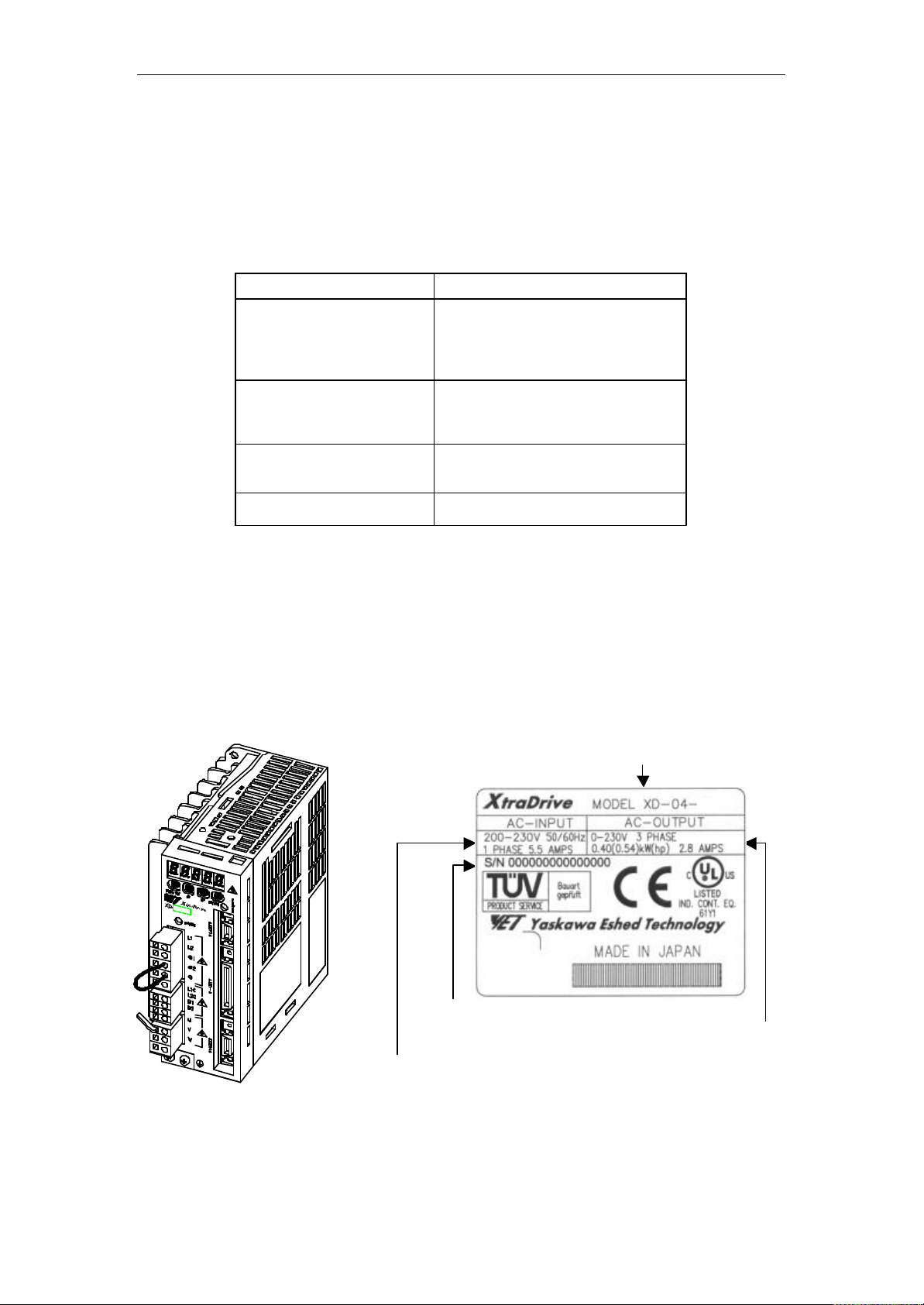
1.1.1. Servo Amplifiers n External Appearance and Nameplate Examples
XtraDrive TYPE
SERIAL NUMBER
SERVOMOTOR OUTPUT
APPLICABLE POWER SUPPLY
1-2
Page 19
XtraDrive User Manual Chapter 1: Checking Product and Part Names
1.2. Product Part Names
This section describes product part names.
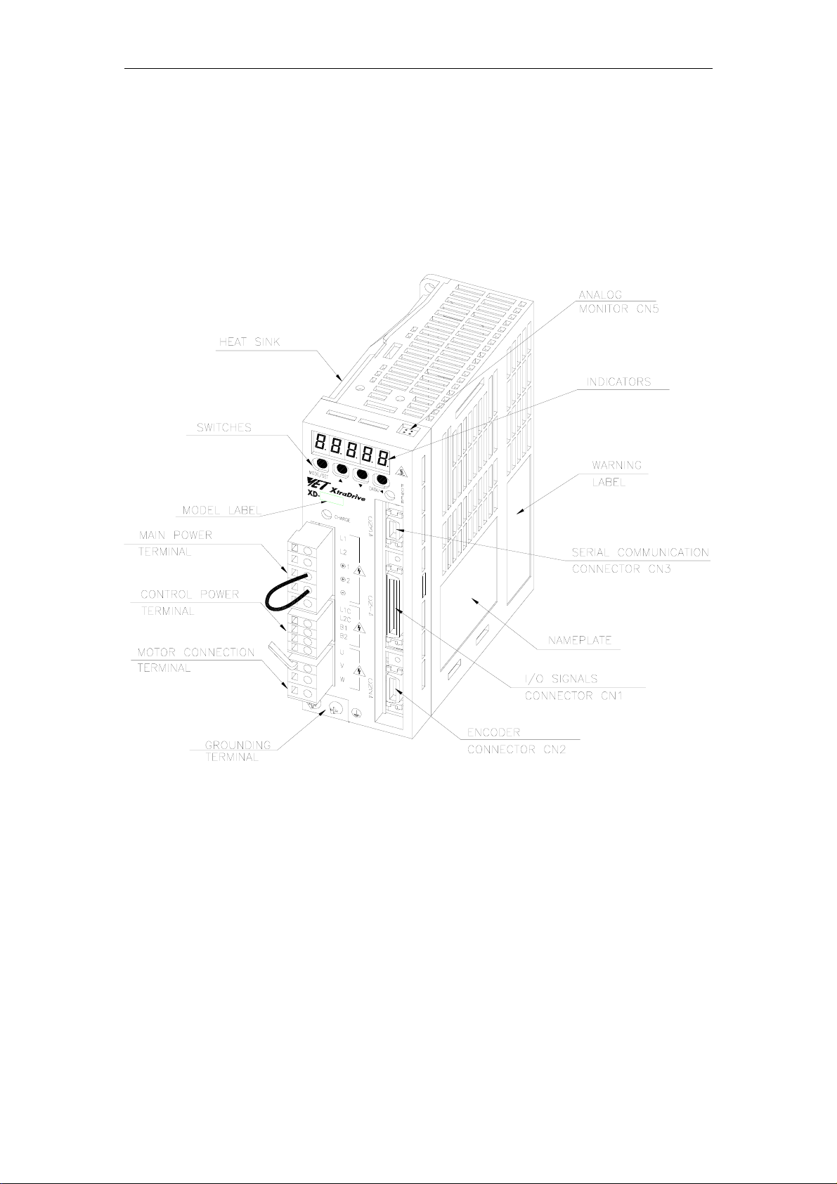
1.2.1. Servo Amplifiers
The figure below shows the part names for servo amplifiers.
1-3
Page 20
XtraDrive User Manual Chapter 1: Checking Product and Part Names
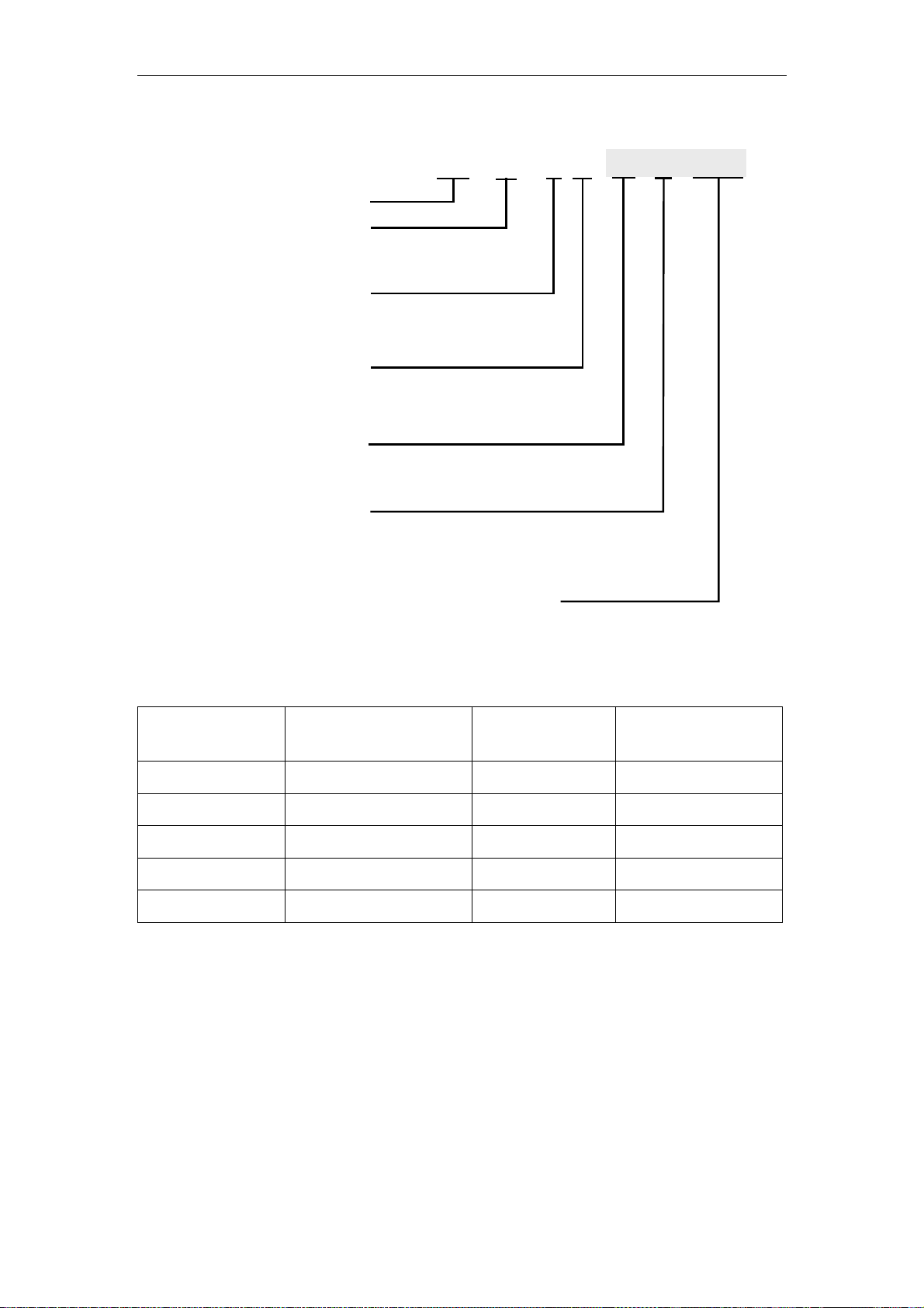
1.2.2. Model Numbers
XtraDrive Series
Max . A pplicabl e
Servomotor Power
(see table below)
Input V olt age:
M - 200VAC, or
T - 400VAC
Extended F unctionality
By Option Boards:
S - no CN10 connector, or
N - with CN10 c onnect or
Desi gn Version #
Bl ank, or 01-FF
(optional)
Bl ank, or
R - Rack m ounted, or
V - B oard coating
(optional)
Bl ank, or Y fol lowed by 1 to 4 alphanum eric characters
to ident ify cus tomer applicat ions
(optional)
Output Capacity
Code
P3 0.03 08 0.75
Max. Applicable
Servomotor Power
(kW)
XD - 01 - M S
Output Capacity
Code
01 R Y999
Max. Applicable
Servomotor Power
(kW)
P5 0.05 10 1.0
01 0.10 15 1.5
02 0.20 20 2.0
04 0.40 30 3.0
1-4
Page 21

XtraDrive User Manual Chapter 2: Inst a lla t i o n
2. Installation
This chapter describes precautions for XtraDrive Series servomotor and servo
amplifier installation.
2.1. Servo Amplifiers.........................................................................................2-2
2.1.1. Storage Conditions..............................................................................2-2
2.1.2. Installation Site ...................................................................................2-2
2.1.3. Orientation ..........................................................................................2-3
2.1.4. Installation...........................................................................................2-3
2-1
Page 22
XtraDrive User Manual Chapter 2: Installation
2.1. Servo Amplifiers
The XtraDrive servo amplifiers are base-mounted. Incorrect installation will
cause problems. Follow the installation instructions below.
2.1.1. Storage Conditions
Store the servo amplifier within the following temperature range, as
long as it is stored with the power cable disconnected.
-20 to 85°C
2.1.2. Installation Site
The following precautions apply to the installation site.
Situation Installation Precaution
Installation in a Control Panel
Installation Near a Heating Unit
Installation Near a Source of Vibration
Design the control panel size, unit layout, and cooling
method so the temperature around the servo amplifier does
not exceed 55°C.
Minimize heat radiated from the heating unit as well as any
temperature rise caused by natural convection so the
temperature around the servo amplifier does not exceed
55°C.
Install a vibration isolator beneath the servo amplifier to
avoid subjecting it to vibration.
Installation at a Site Exposed to
Corrosive Gas
Other Situations
Corrosive gas does not have an immediate effect on the
servo amplifier, but will eventually cause electronic
components and contactor-related devices to malfunction.
Take appropriate action to avoid corrosive gas.
Do not install the servo amplifier in hot and humid locations
or locations subject to excessive dust or iron powder in the
air.
2-2
Page 23
XtraDrive User Manual Chapter 2: Installation
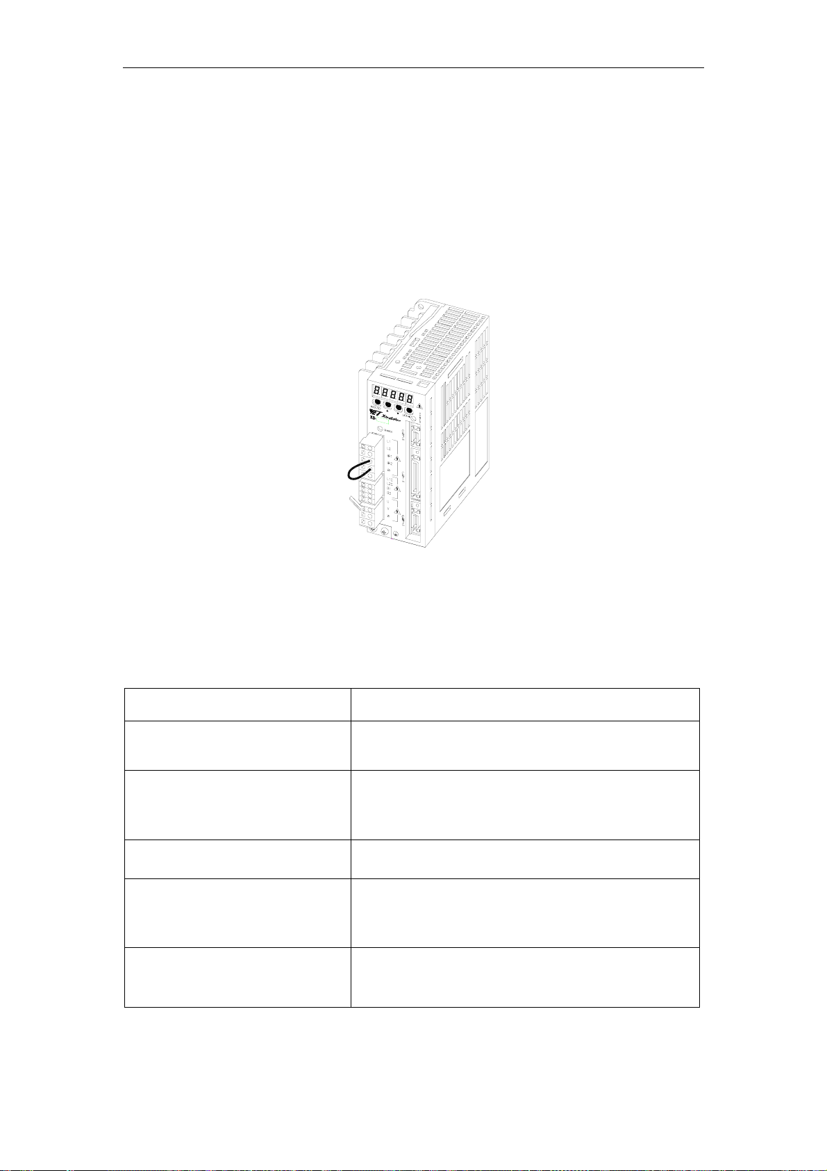
2.1.3. Orientation
Install the servo amplifier perpendicular to the wall as shown in the
figure. The servo amplifier must be oriented this way because it is
designed to be cooled by natural convection or by a cooling fan.
Secure the servo amplifier using the mounting holes. The number of
holes varies (from two to four) with the frame size of the servo
amplifier.
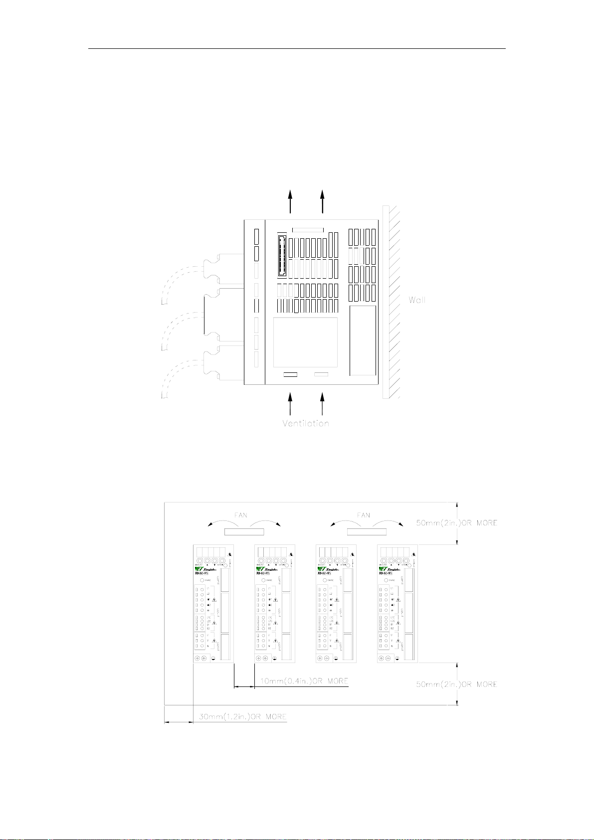
2.1.4. Installation
Follow the procedure below to install multiple servo amplifiers side by
side in a control panel.
2-3
Page 24

XtraDrive User Manual Chapter 2: Installation
Servo Amplifier Orientation
Install the servo amplifier perpendicular to the wall so the front panels’
connectors faces outward.
Cooling
As shown in the figure above, allow sufficient space around each servo
amplifier for cooling by cooling fans or natural convection.
Side-by-side Installation
When installing servo amplifiers side by side as shown in the figure
above, allow at least 0.39in (10mm) between and at least 1.97in
(50mm) above and below each servo amplifier. Install cooling fans
above the servo amplifiers to avoid excessive temperature rise and to
maintain even temperature inside the control panel.
Environmental Conditions in the Control Panel
• Ambient Temperature: 0 to 55°C
• Humidity: 90% RH or less
• Vibration: 0.5 G (4.9m/s
• Condensation and Freezing: None
• Ambient Temperature for Long-term Reliability: 45°C max.
2
)
2-4
Page 25

XtraDrive User Manual Chapter 3: Wiring
3. Wiring
This chapter describes the procedure used to connect XtraDrive Series products
to peripheral devices and gives typical examples of main circuit wiring as well
as I/O signal connections.
3.1. Connecting to Peripheral Devices...............................................................3-2
3.1.1. Single-Phase 200V Main Circuit Specifications.................................3-3
3.1.2. Single-Phase 0.8kW 200V Main Circuit Specifications.....................3-4
3.1.3. Three-phase 200V Main Circuit Specifications..................................3-5
3.1.4. Three-Phase 400V Main Circuit Specifications .................................3-6
3.2. XtraDrive Internal Block Diagrams............................................................3-7
3.2.1. Single-phase 30W to 800W, 200V Models ........................................3-7
3.2.2. Three-phase 1kW to 3kW, 200V Models ...........................................3-8
3.2.3. Three-phase 0.5kW to 3.0kW, 400V Models .....................................3-9
3.3. Main Circuit Wiring..................................................................................3-10
3.3.1. Names and Descriptions of Main Circuit Terminal..........................3-11
3.3.2. Typical Main Circuit Wiring Example.............................................3-12
3.3.3. Servo Amplifier Power Losses .........................................................3-13
3.3.4. Wiring Main Circuit Terminal Blocks..............................................3-14
3.4. I/O Signals ................................................................................................3-15
3.4.1. Example of Typical I/O Signal Connections ....................................3-15
3.4.2. List of CN1 Terminals......................................................................3-16
3.4.3. I/O Signal Names and Functions ......................................................3-17
3.4.4. Interface Circuits...............................................................................3-19
3.5. Wiring Encoders (for SGMGH and SGMSH Motors Only) ....................3-23
3.5.1. Encoder Connections ........................................................................3-23
3.5.2. CN2 Encoder Connector Terminal Layout and Types .....................3-25
3.5.3. Encoder Cables Interconnections......................................................3-26
3.6. Examples of Standard Connections ..........................................................3-28
3-1
Page 26

XtraDrive User Manual Chapter 3: Wiring
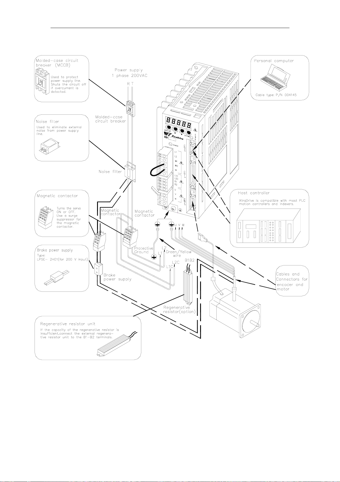
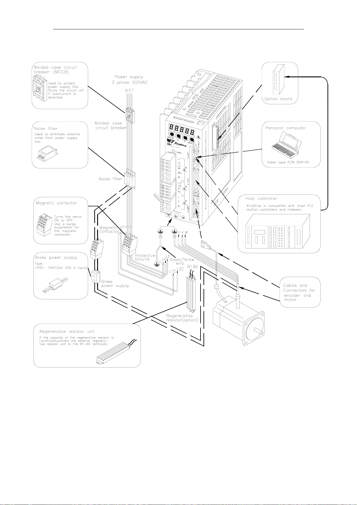
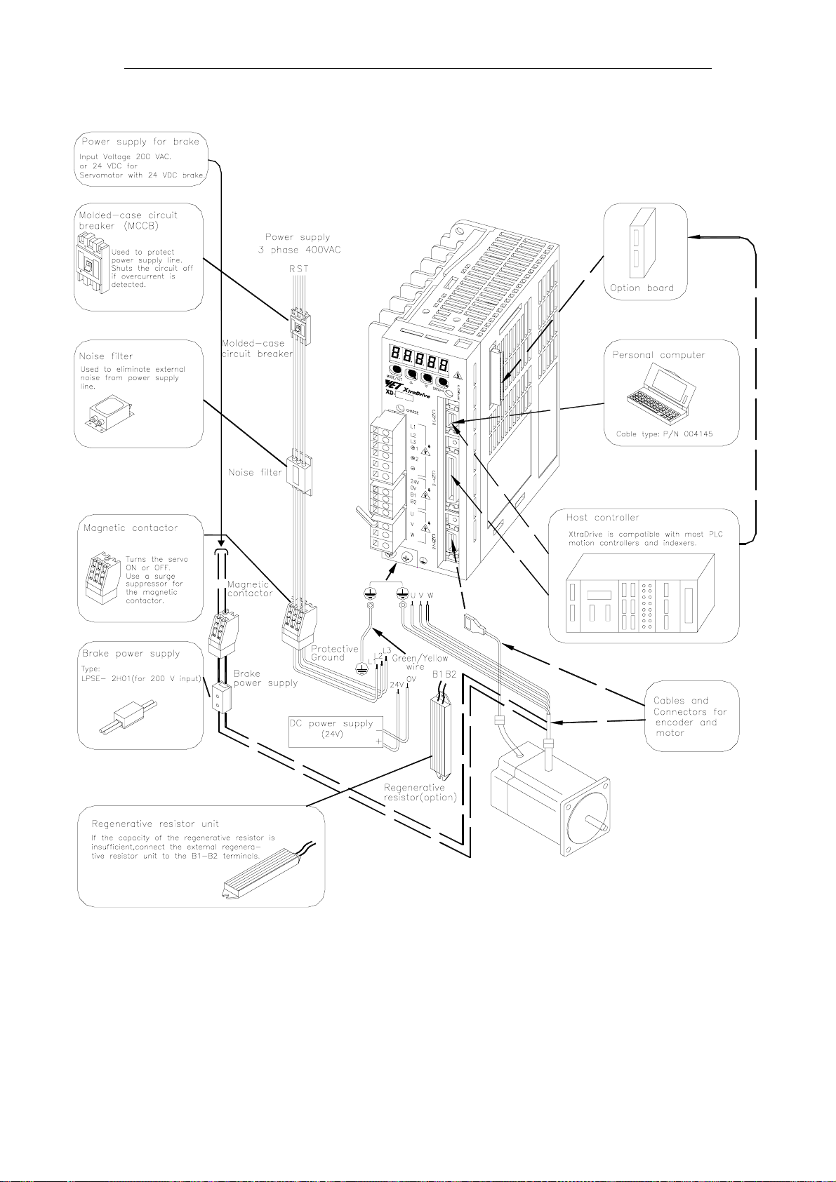
3.1. Connecting to Peripheral Devices
This section provides examples of standard XtraDrive Series product
connections to peripheral devices.
It also briefly explains how to connect each peripheral device.
3-2
Page 27
XtraDrive User Manual Chapter 3: Wiring
3.1.1. Single-Phase 200V Main Circu it Specifications
3-3
Page 28
XtraDrive User Manual Chapter 3: Wiring
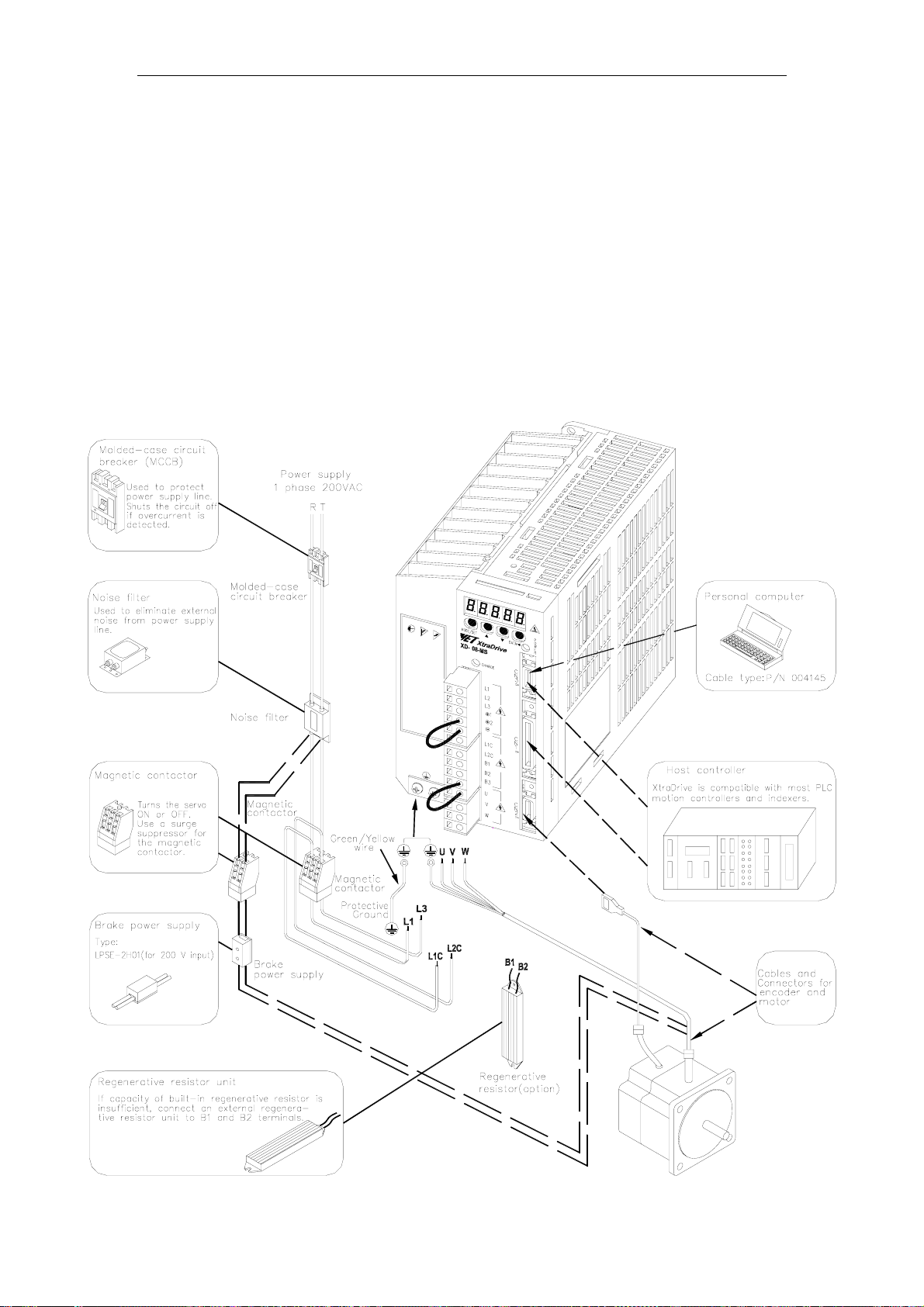
3.1.2. Single-Phase 0.8kW 200V Main Circuit Specifications
XtraDrive XD-08-MS has been changed from three-phase specifications to single-
phase. Main circuit connection terminals (L1, L2, L3) remained.
These devices have terminal B3 and internal regenerative resistor. Observe the
following points.
1. Connect main power supply shown below to L1 and L3 terminals. Power supply is
single-phase, 220 to 230 VAC +10% to –15%, 50/60Hz. If power supply of 187V
(-15% of 220V) or less is used, alarm A.41 indicating voltage shortage, may occur
when accelerating to max speed with max torque of motor.
2. Short-circuit B2 and B3 terminals using the internal regenerative resistor. If
capacity of the regenerative resistor is insufficient, remove the lead between B2
and B3 terminals and connect an external regenerative resistor unit to B1 and B2
terminals.
3-4
Page 29
XtraDrive User Manual Chapter 3: Wiring
3.1.3. Three-phase 200V Main Circuit Specifications
3-5
Page 30
XtraDrive User Manual Chapter 3: Wiring
3.1.4. Three-Phase 400V Main Circuit Specifications
3-6
Page 31

XtraDrive User Manual Chapter 3: Wiring
3.2. XtraDrive Internal Block Diagrams
The following sections show internal block diagrams of the servo amplifiers.
3.2.1. Single-phase 30W to 800W, 200V Models
3-7
Page 32

XtraDrive User Manual Chapter 3: Wiring
3.2.2. Three-phase 1kW to 3kW, 200V Models
3-8
Page 33

XtraDrive User Manual Chapter 3: Wiring
3.2.3. Three-phase 0.5kW to 3.0kW, 400V M odels
3-9
Page 34

XtraDrive User Manual Chapter 3: Wiring
3.3. Main Circuit Wiring
This section shows typical examples of main circuit wiring for XtraDrive
Series servo products, functions of main circuit terminals, and the power ON
sequence.
Observe the following precautions when wiring.
CAUTION
•
Do not bundle or run power and signal lines together in the same duct. Keep power and
signal lines separated by at least 30cm (11.81 in).
Not doing so may cause a malfunction.
• Use twisted pair wires or multi-core shielded-pair wires for signal and encoder (PG)
feedback lines.
The maximum length is 3m (118.11 in) for reference input lines and is 20m (787.40 in) for PG
feedback lines.
• Do not touch the power terminals for 5 minutes after turning power OFF because high
voltage may still remain in the servo amplifier.
Make sure the charge indicator is out first before starting an inspection.
•
Avoid frequently turning power O N and OFF. Do not turn power ON or OFF more than
once per minute.
Since the servo amplifier has a capacitor in the power supply, a high charging current flows
for 0.2s when power is turned ON. Frequently turning power ON and OFF causes main power
devices like capacitors and fuses to deteriorate, resulting in unexpected problems.
3-10
Page 35

XtraDrive User Manual Chapter 3: Wiring
3.3.1. Names and Descriptions o f Main Circuit Terminal
The following table gives the names and a description of main circuit
terminals.
Terminal
Symbol
L1, L2
L1, L2, L3*
U, V, W
L1C, L2C
24V, 0V
(2 places)
B1, B2 or
B1, B2, B3
Table
Name Description
Main circuit AC input
terminal
Servomotor connection
terminal
Control power input
terminal
Ground terminal Connects to the power supply ground terminals and motor ground terminal.
External regenerative
resistor terminal
3.1: Main Circuit Names and Description
30W to 1kW Single-phase 200 to 230V (+10%, -15%), 50/60Hz
1kW to 3kW Three-phase 200 to 230V (+10%, -15%), 50/60Hz
2kW to 3.0kW 400V Three-phase 380 to 480V (+10%, -15%), 50/60Hz
Connects to the Servomotor.
Single-phase 200 to 230V (+10%, -15%), 50/60Hz
30W to 3.0kW
30W to 400W
800W to 3.0kW
Three-phase 200 to 230V (+10%, -15%), 50/60Hz
24VDC (±15%) 400V units only
Normally not connected.
Connect an external regenerative resistor
(provided by customer) between B1 and B2 if the
regenerative capacity is insufficient.
Note: No B3 terminal.
Normally short B2 and B3 (for an internal
regenerative resistor).
Remove the wire between B2 and B3 and connect
an external regenerative resistor (provided by
customer) between B1 and B2 if the capacity of
the internal regenerative resistor is insufficient.
1 and 2.
1 and 2.
1, 2
DC reactor terminal
connection for power
supply harmonic wave
countermeasure
Main circuit Positive
terminal
Main circuit Negative
terminal
Normally short
If a countermeasure against power supply harmonic waves is needed,
connect a DC reactor between
The amplifier is delivered from the factory with these terminals shorted.
See 5.8.6 Reactor for Harmonic Suppression for details.
Normally not connected.
Normally not connected.
*XtraDrive XD-08 has single-phase, 200V power supply specifications. Connect the
following power supply between L1 and L3.
Single-phase 220 to 230 VAC
When a power supply of 187V(-15% of 220V) or less is used, an alarm 41, indicating
voltage shortage, may occur when accelerating to max speed with max torque of motor.
+10%, -15%
(50/60Hz)
3-11
Page 36

XtraDrive User Manual Chapter 3: Wiring
3.3.2. Typical Main Circuit Wiring E xample
The following figure shows a typical example of main circuit wiring.
! Designing a Power ON Sequence
Note the following when designing the power ON sequence.
• Design the power ON sequence so that power is turned OFF when a
servo alarm signal is output. (See the circuit figure above.)
• Hold the power ON button for at least two seconds. The servo
amplifier will output a servo alarm signal for two seconds or less
when power is turned ON. This is required in order to initialize the
servo amplifier.
Power supply
2.0 s max.
Servo alarm (ALM)
output signal
3-12
Page 37

XtraDrive User Manual Chapter 3: Wiring
3.3.3. Servo Amplifier Power Los ses
The following table shows servo amplifier power losses at the rated
output.
Table
3.2: Servo Amplifier Power Losses at Rated Output
Main
Circuit
Power
Supply
Single-
phase
200V
Threephase
200V
Threephase
400V
Maximum
Applicable
Servomotor
Capacity
[kW]
0.10 XD-01-** 0.91 6.7 19.7
0.20 XD-02-** 2.1 13.3 26.3
0.40 XD-04-** 2.8 20
0.75 XD-08-** 4.4 47 12 15 74
1.0 XD-10-** 7.6 55 12 82
2.0 XD-20-** 18.5 120 163
3.0 XD-30-** 7.5 60
0.45 XD-05-** 1.9 19 48
1.0 XD-10-** 3.5 35 64
1.5 XD-15-** 5.4 53
2.0 XD-20-** 8.4 83 161
3.0 XD-30-** 11.9 118
Servo Amplifier
Model
Output
Current
(Effective
Value) [A]
Main
Circuit
Power
Loss
[W]
Regenerative
Resistor
Power Loss
[W]
— 13
28
14
28
Control
Circuit
Power
Loss
[W]
15
15
Note: Regenerative resistor power losses are allowable losses. Take the following action if this value is
exceeded:
• Disconnect the internal regenerative resistor in the servo amplifier by removing the wire
between terminals B2 and B3.
•
Install an external regenerative resistor between terminals B1 and B2.
See 5.6 Selecting a Regenerative Resistor for more details on the resistors.
Total
Power
Loss
[W]
33
198
82
243
3-13
Page 38

XtraDrive User Manual Chapter 3: Wiring
3.3.4. Wiring Main Circuit Term inal Blocks
Observe the following precautions when wiring main circuit terminal
blocks.
CAUTION
•
Remove the terminal block from the servo amplifier prior to wiring.
•
Insert only one wire per terminal on the terminal block.
•
Make sure that the core wire is not electrically shorted to adjacent core wires.
•
Reconnect any wires that were accidentally pulled out.
Servo amplifiers with a capacity below 1.5kW will have connector-type
terminal blocks for main circuit terminals. Follow the procedure below when
connecting to the terminal block.
! Connection Procedure
• Strip the end of the wire, leaving the ends twisted together.
• Open the wire insert opening of the terminal block (plug) with a tool
using either of the two procedures shown in Fig. A and Fig. B on the
following page.
1. Fig. A: Use the provided lever to open the wire insert opening .
Fig. B: Using a commercially available 1/8in (3.0 to 3.5mm)
slotted screwdriver, press down firmly on the screwdriver insert
opening to release the wire insert slot.
2. Figs A and B: Insert the wire end into the opening and then
clamp it tightly by releasing either the lever or the screwdriver.
3-14
Page 39

XtraDrive User Manual Chapter 3: Wiring
3.4. I/O Signals
This section describes I/O signals for the XtraDrive servo amplifier.
3.4.1. Example of Typical I/O Si gnal Connections
3-15
Page 40

XtraDrive User Manual Chapter 3: Wiring
3.4.2. List of CN1 Terminals
The following diagram shows the layout and specifications of CN1
terminals.
2 SG GND
4 SEN
6 SG GND
8 /PULS
10 SG GND
12 /SIGN
14 /CLR Clear input
16 TMON
18 PL3
20 /PCO
22 BAT (-) Battery (-)
24 — —
SEN signal
input
Reference
pulse input
Reference
symbol input
Analog
Monitor Output
Open-collector
reference
power supply
PG divided
output
C-phase
Table
1 SG GND
3 PL1
5 V-REF
7 PULS
9 T-REF
11 SIGN
13 PL2
15 CLR Clear input
17 VTG
19 PCO
21 BAT (+) Battery (+)
23 — —
/V-CMP+
25
(/COIN+)
3.3: CN1 Terminal Layout
Open-collector
reference
power supply
Reference
speed input
Reference
pulse input
Torque
reference input
Reference sign
input
Open-collector
reference
power supply
Analog Monitor
PG divided
output Cphase
Speed
coincidence
detection output
Note: 1. Do not use unused terminals for relays.
2. Connect the shield of the I/O signal cable to the connector’s shell.
3. Connect to the FG (frame ground) at the servo amplifier-end connector.
Output
27 /TGON+
29 /SRDY+
31 ALM+
33 PAO
35 PBO
37 AL01
39 AL03
41 P-CON
43 N-OT
45 /P-CL
47 +24V -IN
49 /PSO
TGON signal
output
Servo ready
output
Servo alarm
output
PG divided
output Aphase
PG divided
output Bphase
Alarm code
output
Opencollector
output
P operation
input
Reverse
overtravel
input
Forward
current limit
ON input
External
input power
supply
S-phase
signal output
/V-CMP-
26
(/COIN-)
28 /TGON
30 /S-RDY
32 ALM
34 /PAO
36 /PBO
38 AL02
40 /S-ON
42 P-OT
/ALMRST Alarm reset
44
46 /N-CL
48 PSO
50 — —
Speed coincidence detection
output
TGON signal
output
Servo ready
output
Servo alarm
output
PG divided
output Aphase
PG divided
output Bphase
Alarm code
output
Servo ON
input
Forward
overtravel
input
input
Reverse
current limit
ON input
S-phase
signal output
! CN1 Specifications
XtraDrive Internal
Connector
10250-52A2JL or Equivalent
50-pin Right Angle Plug
MDR 10150-3000VE 50-pin 10350-52A0-008
Applicable Receptacle Kit (YET P/N: 4J4003)
Connector Case Manufacturer
Sumitomo 3M
Co.
3-16
Page 41

XtraDrive User Manual Chapter 3: Wiring
3.4.3. I/O Signal Names and Functions
The following section describes servo amplifier I/O signal names and
functions.
! Input Signals
Signal Name
Common
/S-ON
/P-CON
P-OT
N-OT
/P-CL
/N-CL
/ALM
-RST
+24V
SEN
BAT+
BATSpeed
Referenc
e
Torque
Referenc
e
Position
Referenc
e
Note: 1. The functions allocated to /S-ON, /P-CON. P-OT, N-OT, /ALM-RST, /P-CL, and /N-CL input
V-REF 5 (6)
T-REF
PULS
/PULS
SIGN
/SIGN
CLR
/CLR
PL1
PL2
PL3
signals can be changed with parameters. (See 5.3.3 Input Circuit Signal Allocation.)
2. Pin numbers in parenthesis ( ) indicate signal grounds.
3. The voltage input range for speed and torque references is a maximum of ±12V.
Pin
No.
Servo ON: Turns ON the servomotor when the gate block
40
in the inverter is released.
41
* Function selected via parameter.
Proportional
operation
reference
Direction
reference
Control mode
switching
Zero-clamp
reference
Reference
pulse block
Forward Run
42
43
45
46
44 Alarm reset: Releases the servo alarm state.
47
IN
4 (2) Initial data request signal when using an absolute encoder.
21
22
9
(10)
7
8
11
12
15
14
3
13
18
prohibited
Reverse Run
prohibited
* Function selected with a parameter.
Forward
current limit ON
Reverse
current limit ON
Internal
speed
switching
Control power supply input for sequence signals: users
must provide the +24V power supply.
Connecting pins for the absolute encoder backup battery.
Speed reference input: ±2 to ±10V/rated motor speed
(Input gain can be modified with a parameter.)
Torque reference input: ±1 to ±10V/rated motor speed
(Input gain can be modified with a parameter.)
Corresponds
to reference
pulse input
Line-driver
Open-
collector
Error counter clear: Clears the error counter during
position control.
+12V pull-up power supply when PULS, SIGN and CLR
reference signals is open-collector outputs (+12V power
supply is built into the servo amplifier).
Input mode
•
•
•
Function
Switches the speed control loop from PI
(proportional/integral) to P (proportional)
control when ON.
With internal reference speed selected:
Switches the direction of rotation.
Position Speed
Speed Torque
Torque
Speed control with zero-clamp function:
reference speed is zero when ON.
Position control with reference pulse stop:
stops reference pulse input when ON.
Overtravel prohibited: stops servomotor
when movable part travels beyond the
allowable range of motion.
Speed
Current limit function used when ON.
With internal reference speed selected:
switches the internal speed settings.
Code + pulse string
CCW/CW pulse
Two-phase pulse (90° phase differential)
Enables
control mode
switching.
Refer-
ence
5.5.2
5.2.1
5.2.7
5.2.1
5.2.6
5.2.7
5.4.3
5.2.10
5.1.2
—
5.1.3
5.2.6
5.5.1
5.2.4
5.2.3
5.2.3
5.2.1
5.2.1
5.2.1
5.2.1
5.2.1
3-17
Page 42

XtraDrive User Manual Chapter 3: Wiring
! Output Signals
Signal Name
Common
Speed
Position
Not used.
Note: 1. Pin numbers in parenthesis () indicate signal grounds.
ALM+
ALM-
/TGON+
/TGON-
/S-RDY+
/S-RDY- 9 30
PAO
/PAO
PBO
/PBO
PCO
/PCO
PSO
/PSO
ALO1
ALO2
ALO3
TMON 16 Analog monitor signal
VTG
/V-CMP+
/V-CMP-
/COIN+
/COIN-
2. The functions allocated to /TGON, /S-RDY, and /V-CMP (/COIN) can be changed via parameters.
Functions /CLT, /VCT, /BK, /WARN, and /NEAR signals can also be changed. (See 5.3.4 Output
Circuit Signal Allocation).
Pin
No.
31
32
27
28
33(1)
34
35
36
19
20
48
49
37
38
39(1)
25
26
25
26
23
24
50
Servo alarm: Turns OFF when an error is detected. 5.5.1
Detection during servomotor rotation: detects
whether the servomotor is rotating at a speed higher
than the motor speed setting. Motor speed detection
can be set via parameter.
Servo ready: ON if there is no servo alarm when the
control/main circuit power supply is turned ON.
A phase
signal
B phase
signal
C phase
signal
S phase
signal
Alarm code output: Outputs 3-bit alarm codes.
Open-collector: 30V and 20mA rating maximum.
17 Analog monitor signal
Speed coincidence (output in Speed Control Mode):
detects whether the motor speed is within the
setting range and if it matches the reference speed
value.
Positioning completed (output in Position Control
Mode): turns ON when the number of error pulses
reaches the value set. The setting is the number of
error pulses set in reference units (input pulse units
defined by the electronic gear).
These terminals are not used.
Do not connect relays to these terminals.
Function Reference
5.5.5
5.5.6
Converted two-phase pulse (A and
B phase) encoder output signal
and origin pulse (C phase) signal:
RS-422 or the equivalent.
With an absolute encoder: outputs
serial data corresponding to the
number of revolutions (RS-422 or
equivalent).
5.2.3
5.5.1
5.5.4
5.5.3
—
3-18
Page 43

XtraDrive User Manual Chapter 3: Wiring
3.4.4. Interface Circuits
This section shows examples of servo amplifier I/O signal connection to
the host controller.
! Interface for Reference Input Circuits
Analog Input Circuit
Analog signals are either speed or torque reference signals at the
impedance below.
• Speed reference input: About 14kΩ
• Torque reference input: About 14kΩ
The maximum allowable voltage for input signals is ±12V.
Reference Position Input Circuit
An output circuit for the reference pulse and error counter clear signal
at the host controller can be either line-driver or open-collector outputs.
These are shown below by type.
• Line-driver Output Example:
• Open-collector Output, Example 1: External power supply
3-19
Page 44

XtraDrive User Manual Chapter 3: Wiring
The following examples show how to select the pull-up resistor R1 so
the input current (I) falls between 7 and 15mA.
Application Examples
R1 =2.2kΩ with
V
CC
= 24V ±5%
R1 =1kΩ with
VCC = 12V ±5%
R1 =180Ω with
VCC = 5V ±5%
• Open-collector Output, Example 2: Using a servo amplifier with an
internal 12V power supply
This circuit uses the 12V power supply built into the servo
amplifier. The input is not isolated in this case.
! Sequence Input Circuit Interface
The sequence input circuit interface connects through a relay or opencollector transistor circuit. Select a low-current relay; otherwise a faulty
contact will result.
3-20
Page 45

XtraDrive User Manual Chapter 3: Wiring
! Output Circuit Interfaces
Any of the following three types of servo amplifier output circuits can
be used. Connect an input circuit at the host controller following one of
these types.
• Connecting to a Line-driver Output Circuit
Encoder serial data converted to two-phase (A and B phase) pulse
output signals (PAO, /PAO, PBO, /PBO), origin pulse signals (PCO,
/PCO) and S phase rotation signals (PCO, /PCO) are output via linedriver output circuits that normally comprise the position control
system at the host controller. Connect the line-driver output circuit
through a line receiver circuit at the host controller.
See 3.5 Wiring Encoders for connection circuit examples.
• Connecting to an Open-collector Output Circuit
Alarm code signals are output from open-collector transistor output
circuits.
Connect an open-collector output circuit through an optocoupler,
relay, or line receiver circuit.
Note: The maximum allowable voltage and current capacities for open-collector circuits are:
• Voltage: 30V
• Current: 20mA
DC
DC
3-21
Page 46

XtraDrive User Manual Chapter 3: Wiring
• Connecting an optocoupler output circuit
An optocoupler output circuits are used for servo alarm, servo ready,
and other sequence output signal circuits.
Connect an optocoupler output circuit through a relay or line
receiver circuit.
Note: The maximum allowable capacities for optocoupler output circuits are:
• Voltage: 30V
• Current: 50mA
DC
DC
• Connecting two XtraDrives (master-slave mode)
Connect output of “master” XtraDrive to “slave” XtraDrive’s input.
• Connecting an external load to XtraDrive’s output.
Maximum current: 50mA.
3-22
Page 47

XtraDrive User Manual Chapter 3: Wiring
3.5. Wiring Encoders (for SGMGH and SGMSH Motors Only)
The following sections describe the procedure for wiring a servo amplifier to
the encoder.
3.5.1. Encoder Connections
The following diagrams show the wiring of the encoder output from the
motor to CN2 of the servo amplifier, and PG output signals from CN1
to the controller. This applies to both incremental and absolute encoders
of SGMGH and SGMSH motors only.
Incremental Serial Encoders
3-23
Page 48

XtraDrive User Manual Chapter 3: Wiring
Absolute Serial Encoders
Incremental A/B+C Encoders
3-24
Page 49

XtraDrive User Manual Chapter 3: Wiring
3.5.2. CN2 Encoder Connector Terminal Layout and Types
The following tables describe CN2 connector terminal layout and types.
CN2 Connector Terminal Layout
1 PPG0V PG GND
2 PPG0V PG GND
3 PPG0V PG GND
4 PPG5V PG +5V
5 PPG5V PG +5V
6 PPG5V PG +5V
7 NC* -
8 PS
10 SPG5V
9 /PS
Serial PG
/S-phase
Serial PG
S-phase
Serial PG
+5V
11 SPG0V
13 BAT-
15 /PC
17 /PA
19 /PB
Serial PG
GND
Battery “ –“
input
PG
/C-phase
PG
/A-phase
PG
/B-phase
12 BAT+
14 PC
16 PA
18 PB
20 NC* -
Note: NC* – Leave contact open.
Optional: CN2 Connector with Commutation Sensors
Terminal Layout
1 PPG0V PG GND
3 PPG0V PG GND
5 PPG5V PG +5V
7 /UIN
9 /VIN
Note: NC* – Leave contact open.
U – Phase
Hall Effect
V – Phase
Hall Effect
10 SPG5V +5V
2 PPG0V PG GND
4 PPG5V PG +5V
6 PPG5V PG +5V
8 NC* -
11 SPG0V GND
12 BAT+
14 PC
16 PA
18 PB
20 /WIN
13 BAT-
15 /PC
17 /PA
19 /PB
Battery ” –“
input
PG
/C-phase
PG
/A-phase
PG
/B-phase
Battery ”+”
input
PG
C-phase
PG
A-phase
PG
B-phase
Battery “+”
input
PG
C-phase
PG
A-phase
PG
B-phase
W – Phase
Hall Effect
CN2 Connector Models
XtraDrive
Internal
Connector
10220-52A2JL
20 PIN
Note: The motor-end relay socket connects to the encoder connector for the SGMAH and SGMPH
servomotors.
Soldered Plug Case
MDR 10120-3000VE 20PIN
(YET P/N: 4J4001)
Applicable Plug (or Socket)
10320-52A0-008
(YET P/N:
4J0101)
3-25
Soldered Plug
(Servomotor
Side)
54280-0600 6PIN
(YET P/N: 4J1521)
Page 50

XtraDrive User Manual Chapter 3: Wiring
3.5.3. Encoder Cables Interconnections
This chapter shows interconnections for all standard encoder cables
available from YET (Refer to YET Part Number). For additional types
of encoders (like with communication sensors etc.) contact your YET
representative.
Absolute A/B Encoder Cable
For Yaskawa SGM motors. (P/N 004143)
XtraDrive side
20-pin connect or
PPG0V 1,2,3
PPG5V 4,5,6
BAT+ 12
BAT- 13
PC 14
/PC 15
PA 16
/PA 17
PB 18
/PB 19
FG Case
BLACK
RED
ORANGE
WHITE
GREEN
WHITE/GREEN
BLUE
WHITE/BLUE
YELLOW
WHITE
YELLOW/GREEN
Cable Shield
P
- Twisted pair.
Incremental A/B Encoder Cable
Motor side
15-pin connect or
70V
8+5V
15 +3.6V
P
14 0V
5C
P
6/C
1A
P
2/A
3B
P
4/B
9FG
For Yaskawa SGM motors. (P/N 004144)
XtraDrive side
20-pin connect or
PPG0V 1,2,3
PPG5V 4,5,6
PC 14
/PC 15
PA 16
/PA 17
PB 18
/PB 19
FG Case
BLACK
RED
GREEN
WHITE/GREEN
BLUE
WHITE/BLUE
YELLOW
WHITE
YELLOW/GREEN
Cable Shield
P
- Twisted pair.
3-26
Motor side
9-pin connect or
70V
8+5V
5C
P
6/C
1A
P
2/A
3B
P
4/B
9FG
Page 51

XtraDrive User Manual Chapter 3: Wiring
Absolute Serial Encoder Cable
For Yaskawa SGMAH motors. (P/N 004139)
XtraDrive side
20-pin connect or
RED
BLACK
ORANGE
WHITE/ORANGE
BLUE
WHITE/BLUE
Cable Shield
Battery
connector
BAT+ 1
BAT- 2
SPG5V 10
SPG0V 11
12
13
PS 8
/PS 9
FG Shield
P
- Twisted pair.
Incremental Serial Encoder Cable
For Yaskawa SGMAH motors. (P/N 004140)
XtraDrive side
20-pin connect or
SPG5V 10
SPG0V 11
BAT+ 12
BAT- 13
PS 8
/PS 9
FG Shield
RED
BLACK
ORANGE
WHITE/ORANGE
BLUE
WHITE/BLUE
Cable Shield
6-pin connect or
P
P
Motor side
6-pin connect or
1PG5V
2GND
3 PGBAT+
P
4 PGBAT-
P
5PS
6 /PS
Shield FG
Motor side
1PG5V
2GND
3 PGBAT+
4 PGBAT-
5PS
6 /PS
Shield FG
P
- Twisted pair.
3-27
Page 52

XtraDrive User Manual Chapter 3: Wiring
3.6. Examples of Standard Connections
The following diagrams show examples of standard servo amplifier
connections by specifications and type of control.
Note for single-phase power supply specifications:
XtraDrive XD-08** have changed from three-phase specifications to singlephase. Main circuit connection terminals (L1, L2, L3) remained.
These devices have terminal B3 and internal regenerative resistor. Observe
the following points.
1. Connect main power supply shown below to L1 and L3 terminals. Power
supply is single-phase, 220 to 230 VAC +10% to –15%, 50/60Hz. If
power supply of 187V (-15% of220V) or less is used, alarm A41
indicating voltage shortage, may occur when accelerating to max speed
with max torque of motor.
2. Short-circuit B2 and B3 terminals using the internal regenerative resistor.
If capacity of the regenerative resistor is insufficient, remove the lead
between B2 and B3 terminals and connect an external regenerative
resistor unit to B1 and B2 terminals.
3-28
Page 53

XtraDrive User Manual Chapter 3: Wiring
Position Control Mode
*1. P represents twisted-pair wires
*2. The time constant for the primary filter is 47us.
*3. Connect only with an absolute encoder.
*4. Used only with an absolute encoder. *8. Use a double-insulated 24-VDC power supply.
between terminals B1 and B2.(for XtraDrives with big
capacity)
*6. These circuits are hazardous, therefore are
separated by protecting separator.
*7. These circuits are SELV circuits, therefore are
separated from all other circuits by double and
reinforced insulator.
*9. Optional – not available in all models. *5. Connect an external regenerative resistor
*10. Resistors are different for each model.
*11. ∅ Represents contacts of CN1 connector
3-29
Page 54

XtraDrive User Manual Chapter 3: Wiring
Speed Control Mode
*1. P represents twisted-pair wires
*2. The time constant for the primary filter is 47us.
*3. Connect only with an absolute encoder.
*4. Used only with an absolute encoder. *8. Use a double-insulated 24-VDC power supply.
between terminals B1 and B2.(for XtraDrives with big
capacity)
*6. These circuits are hazardous, therefore are
separated by protecting separator.
*7. These circuits are SELV circuits, therefore are
separated from all other circuits by double and
reinforced insulator.
*9. Optional – not available in all models. *5. Connect an external regenerative resistor
*10. Resistors are different for each model.
*11. ∅ Represents contacts of CN1 connector
3-30
Page 55

XtraDrive User Manual Chapter 3: Wiring
Torque Control Mode
*1. P represents twisted-pair wires
*2. The time constant for the primary filter is 47us.
*3. Connect only with an absolute encoder.
*4. Used only with an absolute encoder. *8. Use a double-insulated 24-VDC power supply.
between terminals B1 and B2.(for XtraDrives with big
capacity)
*6. These circuits are hazardous, therefore are
separated by protecting separator.
*7. These circuits are SELV circuits, therefore are
separated from all other circuits by double and
reinforced insulator.
*9. Optional – not available in all models. *5. Connect an external regenerative resistor
*10. Resistors are different for each model.
*11. ∅ Represents contacts of CN1 connector
3-31
Page 56

XtraDrive User Manual Chapter 3: Wiring
This page intentionally left blank.
3-32
Page 57

XtraDrive User Manual Chapter 4: Trial Operation
4. Trial Operation
This chapter describes a two-step trial operation. Be sure to complete step 1
before proceeding to step 2.
4.1. Two-Step Trial Operation...........................................................................4-2
4.1.1. Step 1: Trial Operation for Servomotor without Load........................4-3
4.1.2. Step 2: Trial Operation with Servomotor Connected to Machine .....4-9
4.2. Additional Setup Procedures in Trial Operation.......................................4-10
4.2.1. Servomotors with Brakes..................................................................4-10
4.2.2. Position Control by Host Controller.................................................4-11
4.3. Minimum Parameters and Input Signals...................................................4-12
4.3.1. Parameters.........................................................................................4-12
4.3.2. Input Signals .....................................................................................4-12
4-1
Page 58

XtraDrive User Manual Chapter 4: Trial Operation
4.1. Two-Step Trial Operation
Make sure that all wiring is completed prior to starting trial operation.
For your own safety, perform the trial operation in the order given below
(step 1 and 2). See 4.1.1 Trial Operation for Servomotor without Load and
4.1.2 Trial Operation for Servomotor Connected to Mashine for more details
on the trial operation.
Step 1: Trial Operation for Servomotor without Load
Make sure th e Se rv o moto r is wired p rop e rly a n d then turn th e
shaft prior to connecting the Servomotor to the equipment.
Step 2: Trial Operation with the Equipment and Servomotor Connected
Adjust the Servomotor according to equipment characteristics,
connect the Servomotor to the equipment, and perform the trial
operation.
Adjust speed byautotun in g.
Servomotor
XtraDrive
Connect to the equipment
4-2
Page 59

XtraDrive User Manual Chapter 4: Trial Operation
4.1.1. Step 1: Trial Operation for Servomotor without Load
Caution
• Do not operate the servomotor while it is connected to the equipment.
To prevent accidents, initially perform step 1 where the trial operation is conducted under no-
load conditions (with all couplings and belts disconnected).
In step 1, make sure that the servomotor is wired properly as shown
below. Incorrect wiring is generally the reason why servomotors fail to
operate properly during trial operation.
• Check main power supply circuit wiring.
• Check servomotor wiring.
• Check CN1 I/O signal wiring.
Make sure the host controller and other adjustments are completed as
much as possible in step 1 (prior to connecting the servomotor to
equipment).
Note: Check the items on the following pages in the order given during the servomotor trial operation.
See 4.2.1 Servomotors with Brakes, if you are using a servomotor with brakes.
4-3
Page 60

XtraDrive User Manual Chapter 4: Trial Operation
1. Secure the servomotor.
Secure the servomotor mounting plate to the equipment in order to
prevent the servomotor from moving during operation.
2. Check the wiring.
Disconnect the CN1 connector and check the servomotor wiring in
the power supply circuit. CN1 I/O signals are not used, so leave the
connector disconnected.
3. Turn ON power.
Normal display
Exam ple of alarm di splay
Alternative display
Turn ON the servo amplifier’s power. If the servo amplifier has
turned ON normally, the LED display on its front panel will appear
as shown above. Power is not supplied to the servomotor because
the servo is OFF.
If an alarm display appears on the LED indicator as shown above,
the power supply circuit, servomotor wiring, or encoder wiring is
incorrect. In this case, turn OFF power and take appropriate action.
See 9.2 Troubleshooting.
Note: If an absolute encoder is used, it must be set up. Refer to 5.7.4 Absolute Encoder Setup.
4-4
Page 61

XtraDrive User Manual Chapter 4: Trial Operation
4. Operate with the panel operator.
Operate the servomotor using the panel operator. Check to see if the
servomotor runs normally.
See 7.2.2 JOG Operation for more details on the procedure.
5. Connect the signal lines.
Use the following procedure to connect the CN1 connector.
a) Turn OFF power.
b) Connect the CN1 connector.
c) Turn ON power again.
6. Check the input signals.
Check input signal wiring in Monitor Mode using the panel
operator. See 7.1.6 Operation in Monitor Mode for more details on
the procedure.
Turn ON and OFF each signal line to see if the LED monitor bit
display on the panel changes as shown below.
Input s ignal LE D di splay
P-OT
N-OT
/ALM-RST
/P-CL
/N-CL
SEN
/P-CON
/S-ON
Top light s when OFF (hi gh level).
Bottom lights when ON (low level).
4-5
Page 62

XtraDrive User Manual Chapter 4: Trial Operation
Input Signal Status LED Display
OFF (high level) Top LED indicators light.
ON (low level) Bottom LED indicators light.
Note: The servomotor will not operate properly if the following signal lines are not wired correctly. Always
wire them correctly. Short-circuit the signal lines if they will be unused. Input signal selections
(parameters Pn50A to Pn50D) can be used to eliminate the need for external short-circuiting.
Signal Symbol Connector Pin
Number
P-OT CN1-42
N-OT CN1-43
/S-ON CN1-40
+24VIN CN1-47
The servomotor can rotate in forward direction
when this signal line is low (0V).
The servomotor can rotate in reverse direction
when this signal line is low (0V).
The servomotor is turned ON when this signal
line is low (0V). Leave the servomotor OFF.
Control power supply terminal for sequence
signals.
Description
Note: IF an absolute encoder is being used, the servo will not turn ON when the servo ON signal (/S-ON) is
input unless the SEN signal is also ON.
When the SEN signal is checked in Monitor mode, the top of the LED will light because the SEN signal
is high when ON.
7. Turn ON the servo.
XtraDrive
Servomotor
/S-ON
CN1-40
0V
Turn ON servo.
Turn ON the servo using the following procedure.
a) Make sure there are no reference signal inputs.
• Set V-REF (CN1-5) and T-REF (CN1-9) to 0V for speed
and torque control.
• Set PULS (CN1-7) and SIGN (CN1-11) to low for position
control.
b) Turn ON the servo ON signal.
Display with servo ON.
4-6
Page 63

XtraDrive User Manual Chapter 4: Trial Operation
Set /S-ON (CN1-40) to 0V. If everything is normal, the
servomotor will turn ON and the LED indicator on the front
panel will display as shown above. If an alarm display appears,
take appropriate action as described in 9.2 Troubleshooting.
Note: If there is noise in the reference voltage for speed control, the “-” on the left of the 7-segment LED may
flash.
Operation Using Reference Input
The operating procedure here depends on the parameter settings
(control mode selection at memory switch Pn000.1). Use the following
procedure for operations with speed and position control.
Operating Procedure in Speed Control Mode:
Set Pn000.1 to 0
This description applies to the standard speed control setting.
V-REF
SG
XtraDrive
CN1-5
CN1-6
Servomotor
Servomotor rotates at a speed proportional
to the referenc e voltage.
1. Gradually increase the reference speed input (V-REF, CN1-5)
voltage. The servomotor will rotate.
2. Check the following items in Monitor mode. See 7.1.6 Operation in
Monitor Mode.
Un000 Actual motor speed
Un001 Reference speed
• Has the reference speed been input?
• Is the motor speed as defined?
• Does the reference speed coincide with the actual motor speed?
• Does the servomotor stop when the speed reference is 0?
3. If the servomotor rotates at extremely slow speed with 0V specified
for the reference voltage, correct the reference offset value as
described in 7.2.3 Automatic Adjustment of the Speed and Torque
Reference Offset or 7.2.4 Manual Adjustment of the Speed and
Torque Reference Offset.
4. Reset the following parameters to change the motor speed or
direction of rotation.
Pn300
Pn000.0
Sets the reference speed input gain.
See 5.2.1 Speed Reference.
Selects the rotation direction.
See 5.1.1 Switching Servomotor Rotation
Direction.
4-7
Page 64

XtraDrive User Manual Chapter 4: Trial Operation
Operating Procedure In Position Control Mode:
Set Pn000.1 to 1
1. Set the parameter Pn200.0 so that the reference pulse form is the
same as the host controller output form.
To select the reference pulse form: See 5.2.2 Position Reference.
2. Input a slow speed pulse from the host controller and execute lowspeed operation.
XtraDrive
Servomotor
CN1-7
CN1-8
CN1-11
CN1-12
Reference
pulse
Host controller
PULS
/PULS
SIGN
/SIGN
3. Check the following data in Monitor mode. See 7.1.6 Operation in
Monitor Mode.
Un000 Actual motor speed
Un007 Reference pulse speed display
Un008 Position offset
• Has the reference pulse been input?
• Is the motor speed as defined?
• Does the reference speed coincide with the actual motor speed?
• Does the servomotor stop when the speed reference is 0?
4. Reset the parameters shown below to change the motor speed or
direction of rotation.
Pn202, Pn203
Pn000.0
Electronic gear ratio
See 5.2.5 Using the Electronic Gear Function.
Selects the direction of rotation.
See 5.1.1 Switching Servomotor Rotation Direction.
If an alarm occurs or the servomotor fails to operate during the
above operation, the CN1 connector wiring is incorrect or the
parameter settings do not match the host controller specifications.
Check the wiring and review the parameter settings, then repeat
step 1.
Note: References
• List of alarms: See 9.2.3 Alarm Display Table.
• List of parameters: See Appendix D List of Parameters.
4-8
Page 65

XtraDrive User Manual Chapter 4: Trial Operation
4.1.2. Step 2: Trial Operation with Servomotor Connected to Machine
Warning
Follow the procedure below for step 2 operation precisely as given.
Malfunctions that occur after the servomotor is connected to the equipment not only damage the
equipment, but may also cause an accident resulting in death or injury.
Before proceeding to step 2, repeat step 1 (servomotor trial operation
without a load) until all concerns including parameters and wiring have
fully satisfied expectations.
After step 1 has been completed, proceed to step 2 for trial operation
with the servomotor connected to the equipment. The servo amplifier is
now adjusted in the following ways to meet the specific equipment’s
characteristics.
• Using autotuning to match the servo amplifier to the equipment’s
characteristics.
• Matching direction of rotation and speed to the equipment’s
specifications.
• Checking the final control form.
Servomotor
Connect to the machine
XtraDrive
Follow the procedure below to perform the trial operation.
1. Make sure power is OFF.
2. Connect the servomotor to the equipment.
See
2.1 Servomotors for more details on connecting the servomotor.
3. Use autotuning to match the servo amplifier to equipment
characteristics.
See 6.3 Autotuning.
4. Operate the servomotor by reference input.
As in step 1 (
servomotor by reference input as described in
Operation for Servomotor without Load.
Servomotor Trial Operation without Load), operate the
4.1.1 Step 1: Trial
Tune to match the host
controller at this time, as well.
5. Set and record user settings.
Set parameters as required and record all settings for later use during
maintenance.
Note: The servomotor will not be broken in completely during the trial operation. Therefore, let the system
run for a sufficient amount of time after trial operation has been completed to ensure that it is properly
broken in.
4-9
Page 66

XtraDrive User Manual Chapter 4: Trial Operation
4.2. Additional Setup Procedures in Trial Operation
For two equipment configurations, which are delineated in the subsequent
sections, precautionary setup procedures must be followed before starting trial
operation.
4.2.1. Servomotors with Brakes
Use a servomotor with a brake for vertical shaft applications or for the
application of external force to the shaft to prevent rotation due to
gravity or external force during a power loss.
The servo amplifier uses the brake interlock output (/BK) signal to
control the holding brake operation when using servomotors with
brakes.
Vertical shaft
Servomotor
Shaft with External Force Applied
Holding brake
Prevents the
Servom ot or from
rotating due to grav ity.
External
force
Servomotor
Note: To prevent faulty operation when using gravity or external force, first make sure that both the
servomotor and the holding brake work properly. When assured that each operates properly, connect the
servomotor to the rest of the equipment to start the trial operation.
The following figure shows wiring for a servomotor with brakes. See
5.4.4 Using the Holding Brake for details on wiring.
Power supply
Single-phase 200V
XtraDri ve
U,V,W
Servomotor wit h brakes
Encoder
M
PG
Single-phase
200V
Magnetic contactor
CN 2
(90VDC)
Brake power suppl y
LPSE-2H01 (200-V input)
4-10
Page 67

XtraDrive User Manual Chapter 4: Trial Operation
4.2.2. Position Control by Host Controller
If the position control algorithm of the host controller has not been
established or finalized, disconnect the servomotor from the equipment
before performing a trial operation. This will prevent the servomotor
from running out of control and damaging the equipment.
Reference
speed
Host
controller
XtraDrive
M
Check servomotor operation as described in the following table.
Controller
Reference
JOG
Operation
(Constant
Reference
Speed Input
from Host
Controller)
Simple
Positioning
Overtravel
(P-OT and
N-OT Used)
Speed control
Trial operat ion for
servomotor without load
Check Procedure Description
Check motor speed as follows:
Check the parameter
setting at Pn300 to see
if the reference speed
gain is correct.
Check the parameter
setting at Pn201 to see
if the number of
dividing pulses is
correct.
Review P-OT and NOT wiring if the
servomotor does not
stop.
Motor speed
Number of
motor
rotations
Whether the
servomotor
stops rotating
when P-OT
and N-OT
signals are
applied
• Use the speed monitor (Un000) on
the Panel Operator.
• Run the servomotor at low speed.
Input a reference speed of 60rpm, for
example, to see if the servomotor
makes one revolution per second.
Input a reference equivalent to one
servomotor rotation and visually
check to see if the shaft makes one
revolution.
Check to see if the servomotor stops
when P-OT and N-OT signals are
input during continuous servomotor
operation.
4-11
Page 68

XtraDrive User Manual Chapter 4: Trial Operation
4.3. Minimum Parameters and Input Signals
This section describes the minimum parameters and input signals required for
trial operation.
4.3.1. Parameters
See 7.1.5 Operation in Parameter Setting Mode for more details on
setting parameters.
Turn power OFF once after changing any parameter except Pn300.
The change will not be valid until power is restored.
Basic Parameters
Pn000.1
Function Selection Basic Switches:
Control Mode Selection
See 5.3.5
Speed Control
Pn300 Speed Reference See 5.2.1
Pn201 Using the Encoder Signal Output See 5.2.3
Position Control
Pn200.0 Position Reference See 5.2.2
Pn202 Using the Electronic Gear Function (Numerator) See 5.2.5
Pn203 Using the Electronic Gear Function (Denominator) See 5.2.5
Changing Servomotor Rotation Direction
If the specified direction differs from the actual direction of rotation,
wiring may be incorrect . Recheck the wiring and correct if necessary.
Use the following parameter to reverse the direction of rotation.
Pn000.0 Switching Servomotor Rotation Direction See 5.1.1
4.3.2. Input Signals
Input signal selection settings through parameters can be used to
eliminate the need for external short circuits.
Signal Name Pin Number Description
/S-ON Servo ON CN1-40
P-OT
N-OT
Forward run
prohibited
Reverse run
prohibited
CN1-42
CN1-43
See 5.5.2 for more details on turning
ON and OFF the servomotor.
See 5.1.2 for more details on the
overtravel limit switch.
4-12
Page 69

XtraDrive User Manual Chapter 5: Parameter Settings and Functions
5. Parameter Settings and Functions
5.1. Settings According to Device Characteristics.............................................5-4
5.1.1. Switching Servomotor Rotation Direction..........................................5-4
5.1.2. Setting the Overtravel Limit Function................................................5-5
5.1.3. Limiting Torque..................................................................................5-8
5.2. Settings According to Host Controller......................................................5-12
5.2.1. Speed Reference................................................................................5-12
5.2.2. Position Reference ............................................................................5-14
5.2.3. Using the Encoder Signal Output .....................................................5-20
5.2.4. Sequence I/O Signals........................................................................5-23
5.2.5. Using the Electronic Gear Function..................................................5-24
5.2.6. Contact Input Speed Control.............................................................5-29
5.2.7. Using Torque Control.......................................................................5-34
5.2.8. Torque Feed-Forward Function........................................................5-40
5.2.9. Torque Limiting by Analog Voltage Reference ...............................5-42
5.2.10. Reference Pulse Inhibit Function (/INHIBIT)..................................5-44
5.3. Setting Up the Servo Amplifier ................................................................5-45
5.3.1. Parameters.........................................................................................5-45
5.3.2. JOG Speed ........................................................................................5-46
5.3.3. Input Circuit Signal Allocation.........................................................5-46
5.3.4. Output Circuit Signal Allocation......................................................5-50
5.3.5. Control Mode Selection....................................................................5-52
5.4. Setting Stop Functions..............................................................................5-54
5.4.1. Adjusting Offset................................................................................5-54
5.4.2. Servo OFF Stop Mode Selection ......................................................5-55
5.4.3. Using the Zero Clamp Function........................................................5-56
5.4.4. Using the Holding Brake ..................................................................5-58
5.5. Forming a Protective Sequence ................................................................5-61
5.5.1. Using Servo Alarm and Alarm Code Outputs ..................................5-61
5.5.2. Using the Servo ON Input Signal (/S-ON) .......................................5-63
5.5.3. Using the Positioning Completed Output Signal (/COIN) ...............5-64
5.5.4. Speed Coincidence Output (/V-CMP) ..............................................5-65
5.5.5. Using the Running Output Signal (/TGON).....................................5-67
5.5.6. Using the Servo Ready Output Signal (/S-RDY) .............................5-68
5.5.7. Using the Warning Output Signal (/WARN)....................................5-69
5.5.8. Handling Power Loss........................................................................5-71
5.6. Selecting a Regenerative Resistor............................................................. 5-72
5.6.1. External Regenerative Resistor.........................................................5-73
5.6.2. Calculating the Regenerative Power Capacity..................................5-74
5.7. Absolute Encoders ....................................................................................5-78
5.7.1. Interface Circuit ................................................................................5-79
5.7.2. Configuring an Absolute Encoder ....................................................5-80
5.7.3. Absolute Encoder Setup....................................................................5-81
5.7.4. Absolute Encoder Reception Sequence ............................................5-84
5.8. AB Encoders .............................................................................................5-89
5.9. Configuration of Serial Commands for AB Encoders ..............................5-91
5.9.1. Position Control................................................................................5-91
5.9.1.1. Defining User Units for Motion Profiles......................................5-91
5-1
Page 70

XtraDrive User Manual Chapter 5: Parameter Settings and Functions
5.9.1.3. Speed Units...................................................................................5-92
5.9.1.4. Acceleration Units ........................................................................5-93
5.9.1.5. Setting Default Motion Profile Parameters...................................5-94
5.9.1.6. Profile Speed (Pn2A2, Pn2A3) .....................................................5-95
5.9.1.7. Profile Acceleration (Pn2A4, Pn2A5) ..........................................5-95
5.9.1.8. Jerk Smoothing Time (Pn2A6) .....................................................5-95
5.9.1.9. Quick Stop Deceleration (Pn2A8, Pn2A9) ...................................5-96
5.9.1.10. Motion End Window (Pn2C0) ......................................................5-96
5.9.2. Torque Control..................................................................................5-96
5.9.3. Homing .............................................................................................5-97
5.9.4. Digital I/O .........................................................................................5-98
5.9.5. Auto Tuning ......................................................................................5-99
5.10. Auto Running a User Program..............................................................5-99
5-2
Page 71

XtraDrive User Manual Chapter 5: Parameter Settings and Functions
Before Reading This Chapter
This chapter describes the use of each CN1 connector I/O signals in the
XtraDrive servo amplifier as well as the procedure for setting the
related parameters for the intended purposes.
The following sections can be used as references for this chapter.
• List of CN1 I/O signals: See 3.4.3 I/O Signal Names and Functions.
• CN1 I/O signal terminal layout: See 3.4.2 List of CN1 Terminals.
• List of parameters: Appendix D List of Parameters.
• Parameter setting procedure: 7.1.5 Operation in Parameter Setting
Mode
The CN1 connector is used to exchange signals with the host controller
and external circuits.
Parameter Configurations
Parameters are comprised of the types shown in the following table. See
Appendix D List of Parameters.
Type
Function Selection Constants
Servo Gain and Other
Constants
Position Control Constants
Speed Control Constants Pn300 to Pn308
Torque Control Constants Pn400 to Pn40A
Sequence Constants
Others Pn600 to Pn601
Auxiliary Function Execution Fn000 to Fn014
Monitor Modes Un000 to Un00D
Parameter
Number
Pn000 to Pn007
Pn550 to Pn551
Pn100 to Pn11E
Pn1A0 to Pn1C0
Pn200 to Pn216
Pn2A2 to Pn2CB
Pn500 to Pn512
Pn200 to Pn2D2
Description
Select basic and application functions such as
the type of control or the stop mode used when
an alarm occurs.
Set numerical values (speed control).
Set numerical values (position control).
Set position control parameters such as the
reference pulse input form gear ratio and
application setting.
Set speed control parameters such as speed
reference input gain and soft start deceleration
time.
Set torque control parameters such as the
torque reference input gain and
forward/reverse torque limits.
Set output conditions for all sequence signals
and change I/O signal selections and
allocations.
Specify the capacity for an external
regenerative resistor and reserved constants.
Execute auxiliary functions such as JOG Mode
operation.
Enable speed and torque reference
monitoring, as well as monitoring to check
whether I/O signals are ON or OFF.
Encoder Selection Pn190 to Pn193 Encoder type selection
5-3
Page 72

XtraDrive User Manual Chapter 5: Parameter Settings and Functions
5.1. Settings According to Device Characteristics
This section describes the procedure for setting parameters according to the
dimensions and performance characteristics of the equipment used.
5.1.1. Switching Servomotor Rotation Direction
XtraDrive has a Reverse Rotation mode that reverses the direction of
servomotor rotation without rewiring. Forward rotation in the standard
setting is defined as counterclockwise as viewed from the load.
With the Reverse Rotation mode, the direction of servomotor rotation
can be reversed without changing other parameters. Only the direction
(+, −) of shaft motion is reversed.
Standard Setting Reverse Rotation Mode
Forward Reference
Reverse Reference
Encoder output
ccw
from XtraDrive
PAO (phas e A)
PBO (phase B)
Encoder output
cw
fromXtraDrive
PAO (phas e A)
PBO (phase B)
Encoder output
cw
fromXtraDrive
PA O ( p h a s e A )
PBO ( ph a s e B )
Encoder output
ccw
from XtraDrive
PAO (phase A)
PBO (phase B)
Setting Reverse Rotation Mode
Use the parameter Pn000.0.
Parameter Signal Setting Control Mode
Pn000.0 Direction Selection Default Setting: 0
Use the following settings to select the direction of servomotor rotation.
Setting Description
0
1
Forward rotation is defined as counterclockwise
(CCW) rotation as viewed from the load.
Forward rotation is defined as clockwise (CW)
rotation as viewed from the load.
(Standard setting)
(Reverse Rotation Mode)
Speed/Torque Control,
Position Control
5-4
Page 73

XtraDrive User Manual Chapter 5: Parameter Settings and Functions
5.1.2. Setting the Overtravel Limit Function
The overtravel limit function forces movable equipment parts to stop if
they exceed the allowable range of motion.
Using the Overtravel Function
To use the overtravel function, connect the overtravel limit switch input
signal terminals shown below to the correct pins of the servo amplifier
CN1 connector.
Input P-OT CN1-42
Input N-OT CN1-43
Forward Run Prohibited
(Forward Overtravel)
Reverse Run Prohibited
(Reverse Overtravel)
Speed/Torque Control,
Position Control
Speed/Torque Control,
Position Control
Connect limit switches as shown below to prevent damage of
exuipment during linear motion.
Reverse rotation end
Servomotor
Forward rotation end
XtraDrive
CN1 -42
CN1 -43
P- OT
N - OT
The drive status with an input signal ON or OFF is shown in the
following table.
Signal State Input Level Description
ON CN1-42: low
P-OT
OFF CN1-42: high
ON CN1-43: low
N-OT
OFF CN1-43: high
Forward rotation allowed, (normal
operation status).
Forward rotation prohibited
(reverse rotation allowed).
Reverse rotation allowed, (normal
operation status).
Reverse rotation prohibited
(forward rotation allowed).
Enabling/Disabling Input Signals
Set the following parameters to specify whether input signals are used
for overtravel or not. The default setting is “NOT USED.”
Parameter Signal Setting Control Mode
Pn50A.3
Pn50B.0
P-OT Signal Mapping
(Forward Run Prohibit Input
Signal)
N-OT Signal Mapping
(Reverse Run Prohibit Input
Signal)
Default Setting: 8
Default Setting: 8
5-5
Speed/Torque
Control, Position
Control
Speed/Torque
Control, Position
Control
Page 74

XtraDrive User Manual Chapter 5: Parameter Settings and Functions
Servomotor Stop Mode for P-OT and N-OT Input Signals
Set the following parameters to specify the servomotor Stop mode when
P-OT and N-OT input signals are used.
Specify the servomotor Stop mode when either of the following signals
is input during servomotor operation.
• Forward run prohibited input (P-OT, CN1-42)
•
Reverse run prohibited input (N-OT, CN1-43)
• Set the parameters according to limit switch type (NO or NC).
Parameter Signal Setting Description
Uses the P-OT input signal to prevent
forward rotation. (Forward rotation is
prohibited when CN1-42 is open and is
allowed when CN1-42 is at 0V).
Does not use the P-OT input signal to
prevent forward rotation. (Forward
rotation is always allowed and has the
same effect as shorting CN1-42 to 0V).
Inputs the reverse signal from CN1-42
input terminal.
Pn50A.3
P-OT Signal
Mapping
(Forward Run
Prohibit Input
Signal)
Example: 2
Default Setting: 8
Example: B
For more options of parameters Pn50A.3 and Pn50B.0 refer to Appendix D.3. Input Signal
Selections
Uses the N-OT input signal to prevent
reverse rotation. (Reverse rotation is
prohibited when CN1-43 is open and is
allowed when CN1-43 is at 0V).
Does not use the N-OT input signal to
prevent reverse rotation. (Reverse
rotation is always allowed and has the
same effect as shorting CN1-43 to 0V).
Inputs the reverse signal from CN1-43
input terminal.
Pn50B.0
N-OT Signal
Mapping
(Reverse Run
Prohibit Input
Signal)
Example: 3
Default Setting: 8
Example: C
Connection example:
Normally Closed type
P-OT
XtraDrive
CN1-42
N-OT
CN1-43
COM of 24V
5-6
Page 75

XtraDrive User Manual Chapter 5: Parameter Settings and Functions
Parameter Signal Setting Control Mode
Speed/Torque
Pn001.1 Overtravel Stop Mode Default Setting: 0
Control, Position
Control
Overtravel
Pn001.0 = 0
Pn001.1 = 0
Pn001.1 = 1 or 2
Note: For torque control, the servomotor will be placed in coast status after either decelerating or coasting to a
stop (according to the stop mode set in Pn001.0), regardless of the setting of Pn001.1.
Stop Mode After Stopping
Stop by
dynamic brake
1
2
Coast to a stop
Decelerate
to a stop
Coast status
Zero clamp
Coast status
Pn001.1
setti ng
0
1
2
Parameter Signal Setting Control Mode
Stops the servomotor the same way as
turning the servo OFF (according to Pn001.0).
Decelerates the servomotor to a stop at the
preset torque, and then locks the servomotor
in Zero Clamp mode.
Torque setting: Pn406 Emergency Stop
Torque
Decelerates the servomotor to a stop at the
preset torque, and puts the servomotor in
coast status.
Torque setting: Pn406 Emergency Stop
Torque
Pn001.1
0
1
Overtravel Stop
Mode
2
Pn406 specifies the stop torque applied for overtravel when the input
signal for prohibiting forward or reverse rotation is used.
The torque limit is specified as a percentage of rated torque.
Parameter Signal
Emergency Stop Torque
Pn406
(Valid when Pn001.1 is 1
or 2)
Forward run
prohibit input
P- OT ( CN1 -42)
Reverse run
prohibit input
N - OT ( CN1 -43)
Setting (%)
Range: 0% to Maximum Torque
Default Setting: 800
Stop Mode
Stop by dynamic brake
Coast to a stop
Decelerate to a stop
Max. torque setting for an
emergency stop
Pn406
5-7
Control Mode
Speed/Torque
Control, Position
Control
Page 76

XtraDrive User Manual Chapter 5: Parameter Settings and Functions
5.1.3. Limiting Torque
The XtraDrive servo amplifier limits torque as follows:
• Level 1: Limits maximum output torque to protect equipment or
workpiece.
• Level 2: Limits torque after the servomotor moves the equipment to
a specified position (external torque limit).
• Level 3: Always limits output torque rather than speed.
• Level 4: Switches between speed and torque limit.
The application of level 1 and 2 in the torque limit function is described
below.
Setting Level 1: Internal Torque Limits
Maximum torque is limited to the values set in the following
parameters.
Parameter Signal Setting (%) Control Mode
Pn402 Forward Torque Limit
Pn403 Reverse Torque Limit
Range: 0 to 800
Default Setting: 800
Range: 0 to 800
Default Setting: 800
Sets the maximum torque limits for forward and reverse rotation.
Speed/Torque
Control, Position
Control
Speed/Torque
Control, Position
Control
Used when torque must be limited due to equipment conditions.
The torque limit function always monitors torque and outputs the
signals below when the limit is reached.
Signal Description
/CLT
Monitor Mode (Un006) Output signal monitor
Generated when Pn50F.0 allocates an output terminal from SO1 to
SO3.
Torque limits are specified as a percentage of the rated torque.
Note: If the torque limit is set higher than the maximum torque of the servomotor, the maximum torque of the
servomotor is the limit.
Application Example: Equipment Protection
Motor
speed
Torque limit
Too small a torque limit will result in an
insufficient torque during acceleration and
deceleration
Torque
5-8
Page 77

XtraDrive User Manual Chapter 5: Parameter Settings and Functions
Using the /CLT Signal
The following section describes the use of the contact output signal
/CLT as a torque limit output signal.
Output /CLT CN1-*1 Torque Limit Output
This signal indicates whether the servomotor output torque (current) is
being limited.
Status Conditions Description
ON
OFF
The circuit between CN1-1 and 2
is closed.
CN1-1 is at low level.
The circuit between CN1-1 and 2
is open.
CN1-1 is at high level.
Servomotor output torque is being limited.
(Internal torque reference is greater than the
limit setting).
Servomotor output torque is not being
limited. (Internal torque reference is less
than the limit setting).
Settings: Pn402 (Forward Torque Limit)
Pn403 (Reverse Torque Limit)
Pn404 (Forward External Torque Limit): /P-CL input only
Pn405 (Reverse External Torque Limit): /N-CL input only
When the /CLT signal is used, the following parameter must be used to
select the output signal.
Parameter Signal Setting Control Mode
Pn50F
Output Signal
Selections 2
Default Setting: 0000
Speed/Torque Control,
Position Control
Speed/Torque
Control, Position
Control
Pn50F.0
/CLT
Torque limit
detection
Output terminal
CN1-25, 26 (SO1)
CN1-27, 28 (SO2)
CN1-29, 30 (SO3)
Use the following table to select which terminal will output the /CLT signal.
Parameter Setting
0 — —
Pn50F.0
1 25 26
2 27 28
3 29 30
Output Terminal (CN1-)
*
1
*
2
Note: Multiple signals allocated to the same output circuit are output using OR logic. Set other output signals
to a value other than the one allocated to the /CLT signal in order to use just the /CLT output signal. See
5.3.4 Output Circuit Signal Allocation.
5-9
Page 78

XtraDrive User Manual Chapter 5: Parameter Settings and Functions
Setting Level 2: External Torque Limit
A contact input signal is used to enable the torque (current) limits
previously set in parameters. Torque limits can be set separately for
forward and reverse rotation.
XtraDrive
Reverse
rotation
/P-CL
CN1-45
Forward
rotation
/N-CL
CN1-46
Input /P-CL CN1-45
Output /N-CL CN1-46
Rotation
speed
Torque
Rotation
speed
Torque
Rotation
speed
Torque
Rotation
speed
Torque
Forward External Torque Limit
Input
Reverse External Torque Limit
Input
Torque limit
Pn402
Torque limit
Pn402 or Pn404
(limited by whichever
is smaller)
Torque limit
Pn403
Torque limit
Pn403 or Pn405
(limited by whichever
is smaller)
Speed/Torque Control, Position
Control
Speed/Torque Control, Position
Control
This is the external torque (current) limit input for forward and reverse
rotation.
Check input signal allocation status when using this function (see 5.3.3
Input Circuit Signal Allocation). Default settings are given in the table
below.
Signal Signal Status Comments Description
CN1-45 at low level when ON Use forward torque limit. Limit: Pn404
/P-CL
CN1-45 at high level when OFF
CN1-46 at low level when ON Use reverse torque limit. Limit: Pn405
/N-CL
CN1-46 at high level when OFF
Do not use forward torque
limit. Normal operation.
Do not use reverse torque
limit. Normal operation.
—
—
5-10
Page 79

XtraDrive User Manual Chapter 5: Parameter Settings and Functions
The following output signals and monitor methods are used when
torque is being limited.
Signal Description
/CLT
Monitor Mode (Un006) —
•
Un005: Numbers 6 and 7 (with default
settings)
•
Un006: Depending on output signal
allocation conditions.
Generated when Pn50F.0 is allocated to an
output terminal from SO1 to SO3.
Refer to 7.1.6 Operation in Monitor Mode.
—
Application Examples:
• Forced stop
• Robot holding a workpiece
Parameter Signal Setting (%) Control Mode
Speed/Torque
Control, Position
Control
Speed/Torque
Control,
Position Control
Pn404 Forward External Torque Limit
Pn405 Reverse External Torque Limit
Range: 0 to 800
Default Setting: 100
Range: 0 to 800
Default Setting: 100
Set the torque limits when the torque is limited by an external contact
input.
Signal Description
/P-CL (CN1-45) Input Pn404 torque limit applied.
/N-CL (CN1-46) Input Pn405 torque limit applied.
See 5.2.9 Torque Limiting by Analog Voltage Reference.
Using /P-CL and /N-CL Signals
The procedure for using /P-CL and /N-CL as torque limit input signals
is illustrated below.
5-11
Page 80

XtraDrive User Manual Chapter 5: Parameter Settings and Functions
5.2. Settings According to Host Controller
This section describes the procedure for connecting a XtraDrive Series servo
to a host controller, including the procedure for setting related parameters.
5.2.1. Speed Reference
Input the speed reference using the input signal: Speed Reference Input.
Since this signal has various uses, set the optimal reference input for the
system created.
Xtr aDr ive
Torque reference input
(analog voltage input)
Speed reference input
(analog voltage input)
Input V-REF CN1-5
Input SG CN1-6
The above inputs are used for speed control (analog reference).
(Pn000.1 = 0, 4, 7, 9, or A.) Always wire for normal speed control.
Refer to 7.1.6 Operation in Monitor Mode.
controlled in proportion to the input voltage between V-REF and SG.
CN1-9
P
CN1-10
CN1-5
P
CN1-6
P
represents twisted-pair wires
Speed Reference Input Speed Control
Signal Ground Speed Control
The motor speed is
Rated motor speed
Factory s etting
-8-12
-4
Torque
reference
Speed
reference
Setting Examples
Pn300 = 600: This setting means that 6V is equivalent to the rated
motor speed.
Speed Reference
Input
+6V
+1V
-3V
Parameter Pn300 can be used to change the voltage input range.
Rotation Direction Motor Speed
Forward rotation Rated motor speed
Forward rotation (1/6) rated motor speed
Reverse rotation (1/2) rated motor speed
12
8
4
Input voltage (V)
Rated motor speed
The slope is set in Pn300.
5-12
SGMAH
Servomotor
3000rpm
500rpm
1500rpm
Page 81

XtraDrive User Manual Chapter 5: Parameter Settings and Functions
Input Circuit Example
+12V
470Ω, 1/2W min.
Ω
2k
V-REF
Xtr aDr ive
CN1-5
P
CN1-6
SG
Always use twisted pair cable for noise control.
Recommended variable resistor: Model 25HP-10B manufactured by
Sakae Tsushin Kogyo Co., Ltd.
Connect V-REF and SG to the speed reference output terminals on the
host controller when using a host controller, such as a programmable
controller, for position control.
Host controller
Speed
reference
output
terminals
Feedback
pulse input
terminals
V-R EF
P
P
P
SG
PAO
/PAO
PBO
/PBO
Xtr aDri ve
CN1-5
CN1-6
CN1-33
CN1-34
CN1-35
CN1-36
P: Indicates twisted-pair wires
Adjust Pn300 according to the output voltage specifications of the host
controller.
Adjust the speed reference input adjustment factor in the following
parameter.
Parameter Signal Setting Control Mode
Pn300
Speed Reference Input
Adjustment Factor
Range: 150 to 3000 x
(0.01V/ rated motor speed)
Speed Control
Set the voltage range for the V-REF speed reference input at CN1-5
according to the host controller and external circuit output range.
Reference
speed (rpm)
Reference
volt age (V)
Set this slope
The default setting is adjusted so that a 6V input is equivalent to the
rated motor speed of all applicable servomotors.
Note: The maximum allowable voltage to the speed reference input (between CN1-5 and 6) is ± 12V
DC
.
5-13
Page 82

XtraDrive User Manual Chapter 5: Parameter Settings and Functions
Using the /P-CON Signal
Input P-CON CN1-41
The /P-CON input signal switches the Speed Control mode from PI
(proportional-integral) to P (proportional) control.
Proportional control can be used in the following two ways:
• When an operation is performed by sending speed references from
the host controller to the servo amplifier, the host controller can
selectively use the P control mode for particular conditions only.
This method can prevent the occurrence of overshoot and also
shorten settling time.
• If PI control mode is used when the speed reference has a reference
offset, the motor may rotate at a very slow speed and fail to stop
even if 0 is specified as speed reference. In this case, use the P
control mode to stop the motor.
Proportional Control
Reference
Speed Control, Position
Control
5.2.2. Position Reference
The reference pulse, reference code, and clear inputs are used for the
position reference. Since this signal can be used in different ways, set
the optimal reference input for the system created.
Reference by Pulse Input
Positioning is controlled by entering a reference pulse for a move.
Any of the following forms can be used for the position reference:
• Line-driver output
• +12V open-collector output
• +5V open-collector output
5-14
Page 83

XtraDrive User Manual Chapter 5: Parameter Settings and Functions
Connection Example 1: Line-driver Output
Applicable line driver: SN75174, manufactured by Texas Instruments
Inc., MC3487 or equivalent
Ω
Connection Example 2: Open-collector Output
Set limiting resistor R1 so that input current I falls within the following
range:
Ω
The examples below show how to select the pull-up resistor R1 so that
the input current I falls between 7 and 15mA.
CC
R1 = 1kΩ with V
Application Examples of V = IR
= 12V ±5% R1 = 180Ω with V
CC
Note: The following table shows the signal logic for an open-collector output.
Tr1 Output Level Signal Logic
ON Equivalent to high-level input
OFF Equivalent to low-level input
= 5V ±5%
5-15
Page 84

XtraDrive User Manual Chapter 5: Parameter Settings and Functions
This circuit uses the 12V power supply built into the servo amplifier.
The input is not isolated in this case.
Ω
Ω
The noise margin of the input signal will decrease if the reference pulse is provided by an open-
Note:
collector output. Set parameter Pn200.3 to 1 if the position drifts due to noise.
Selecting a Reference Pulse Form
Use the following parameters to select the reference pulse form used.
Input PULS CN1-7 Reference Pulse Input Position Control
Input /PULS CN1-8 Reference Pulse Input Position Control
Input SIGN CN1-11 Reference Code Input Position Control
Input /SIGN CN1-12 Reference Code Input Position Control
The servomotor only rotates at an angle proportional to the input pulse.
Parameter Signal Setting Range Control Mode
Pn200.0 Reference Pulse Form Default Setting: 0 Position Control
Set reference pulse form input to the servo amplifier from the host
controller.
Note: This function works only with a Pulse Reference, not with a Serial Command.
Position
reference
pulse
Host
controller
PULSE
SIGN
Xt r a D r i ve
CN1-7
CN1-11
Since the reference pulse form can be selected from among those listed
below, set one according to host controller specifications.
5-16
Page 85

XtraDrive User Manual Chapter 5: Parameter Settings and Functions
Reference
Pulse Form
Pn200.0
Parameter
Input
Pulse
Logic
Multiplier
Forward Rotation
Reference
PULS
0
Sign + pulse
train
---
(CN1-7)
SIGN
(CN1-11)
PULS
CW pulse +
1
CCW pulse
2 x1
Two-phase
pulse train
3 x2
4
5
with 90°
phase
differential
Sign + pulse
train
---
x4
---
(CN1-7)
SIGN
Positive
(CN1-11)
PULS
(CN1-7)
SIGN
(CN1-11)
PULS
(CN1-7)
SIGN
(CN1-11)
Low
High
Low
90°
PULS
(CN1-7)
SIGN
(CN1-11)
PULS
(CN1-7)
SIGN
(CN1-11)
PULS
(CN1-7)
SIGN
(CN1-11)
PULS
(CN1-7)
SIGN
(CN1-11)
Reverse Rotation
Reference
Low
Low
90°
High
PULS
CW pulse +
6
CCW pulse
7 x1
Two-phase
pulse train
8 x2
9
with 90°
phase
differential
---
x4
(CN1-7)
SIGN
(CN1-11)
Negative
PULS
(CN1-7)
SIGN
(CN1-11)
Input Pulse Multiplier
High
90°
PULS
(CN1-7)
SIGN
(CN1-11)
PULS
(CN1-7)
SIGN
(CN1-11)
High
90°
The input pulse multiplier function can be used if the reference pulse is
a two-phase pulse train with a 90° phase differential. The electronic
gear function can also be used to convert input pulses.
5-17
Page 86

XtraDrive User Manual Chapter 5: Parameter Settings and Functions
%
Example of I/O Signal Generation Timing
t2
µ
t6
Note: 1.
Reference
Pulse Form
Sign + pulse
train input
(SIGN +
PULS signal)
Maximum
reference
frequency:
500kpps
(200kpps
open-collector
output)
CW pulse and
CCW pulse
Maximum
reference
frequency:
500kpps
(200kpps
open-collector
output)
Two-phase
pulse train
with 90º
phase
differential (A
phase + B
phase)
Maximum
reference
frequency x1:
500kpps
(200kpps
open-collector
output)
x2: 400kpps
x4: 200kpps
For the input pulse to register, the interval from the time the servo ON signal is turned ON until a
reference pulse is entered must be a minimum of 40ms.
The error counter clear signal must be ON for at least 20µs.
2.
Reference Pulse Input Signal Timing
Electrical Specifications Remarks
t3
t4
t7
t6t5
T
T
t1
t2
t3
t1
T
t2
t1, t2 0.1 s
t3, t7 0.1 s
t4, t5, t6 > 3 s
( /T) x 100 50
t3 > 3 s
1.0 s
t1, t2 0.1 s
( /T) x 100 =
Sign
(SIGN)
H =
Forward
reference
L =
Reverse
reference
—
Parameter
Pn200.0 is
used to
switch the
input pulse
multiplier
mode.
5-18
Page 87

XtraDrive User Manual Chapter 5: Parameter Settings and Functions
Error Counter Clear Input
The procedure for clearing the error counter is described below.
Input CLR CN1-15
Input /CLR CN1-14
The following occurs when the CLR signal is set to high level.
• The error counter inside the servo amplifier is set to 0.
• Position loop control is prohibited.
Use this signal to clear the error counter of the host controller or select
the following clear operation through parameter Pn200.1.
Parameter Signal Setting Range Control Mode
Pn200.1 Error Counter Clear Signal Form Default Setting: 0 Position Control
Select the pulse form for the error counter clear signal CLR (CN1-15).
Pn200.1
Setting
Description Clear Timing
Clear Input Position Control
Clear Input Position Control
Xt r a Dr i ve
CLR
Clear
Posit ion loop
error count er
Clears the error counter when the CLR signal goes
0
1
2
3
high.
Error pulses do not accumulate as long as the signal
remains high.
Clears the error counter on the rising edge of the CLR
signal.
Clears the error counter only once on the rising edge of
the CLR signal.
Clears the error counter when the CLR signal goes low.
Error pulses do not accumulate as long as the signal
remains low.
Clears the error counter on the falling edge of the CLR
signal.
Clears the error counter only once on the falling edge of
the CLR signal.
CLR
(CN1-15)
CLR
(CN1-15)
Cleared only once at this point
CLR
(CN1-15)
CLR
(CN1-15)
Cleared only once at thi s point
High
Cleared state
High
Low
Cleared st ate
Low
5-19
Page 88

XtraDrive User Manual Chapter 5: Parameter Settings and Functions
5.2.3. Using the Encoder Signal Output
Encoder output signals are divided inside the servo amplifier and can be
output externally. These signals can be used to form a position control
loop in the host controller.
These output s
explained here
Xt r a D r i ve
Encoder
PG
CN1
Frequenc y
div iding
circuit
CN2
Phase A
Phase B
Phase C
Host
controller
The output circuit is for line-driver output. Connect each signal line
according to the following circuit diagram.
Dividing means converting an input pulse train from the encoder mounted on the servomotor according
Note:
to the preset pulse density and outputting the converted pulse. The units are pulses per revolution (PPR).
I/O Signals
I/O signals are described below.
Output PAO CN1-33 Encoder Output Phase A Speed/Torque Control, Position Control
Output /PAO CN1-34 Encoder Output Phase /A Speed/Torque Control, Position Control
Output PBO CN1-35 Encoder Output Phase B Speed/Torque Control, Position Control
Output /PBO CN1-36 Encoder Output Phase /B Speed/Torque Control, Position Control
Output PCO CN1-19 Encoder Output Phase C Speed/Torque Control, Position Control
Output /PCO CN1-20 Encoder Output Phase /C Speed/Torque Control, Position Control
Divided encoder signals are outputs; therefore always connect these signal terminals
when a position loop is formed in the host controller for position control.
Set a dividing ratio using the following parameter: PG Dividing Ratio Pn201
The dividing ratio setting is not related to the gear ratio setting (Pn202 and 203) for
the servo amplifier electronic gear function during position control.
5-20
Page 89

XtraDrive User Manual Chapter 5: Parameter Settings and Functions
Output Phase Form
Forward
rotation
90
°
Reverse
rotation
90
°
t
Input SEN CN1-4 SEN Signal Input Speed/Torque Control
Input /SEN CN1-2 Signal Ground Speed/Torque Control
Output PSO CN1-48 Encoder Output Phase S Speed/Torque Control, Position Control
Output /PSO CN1-49 Encoder Output Phase /S Speed/Torque Control, Position Control
Input BAT (+) CN1-21 Battery (+) Speed/Torque Control, Position Control
Input /BAT (-) CN1-22 Battery (-) Speed/Torque Control, Position Control
t
Use SEN to BAT (-) signals for absolute encoders. See 5.7 Absolute Encoders for
more details.
Output SG CN1-1 Signal ground Speed/Torque Control, Position Control
SG: Connect to 0V on the host controller.
IMPORTANT
When using the servo amplifier phase C pulse signal to return to the machine origin,
•
always turn the servomotor at least twice before starting the original return operation.
If the configuration of the mechanical system prevents turning the servomotor before the
origin return operation, then perform the origin return operation at a servomotor speed of
600rpm or below. The phase C pulse signal may not be correctly applied if the servomotor
turns faster than 600rpm.
Pulse Divider Setting
Set the pulse dividing ratio in the following parameter:
Parameter Signal Setting (PPR) Control Mode
Pn201 PG Divider
Range: 0 to 65535
Default Setting: 2048
Serial encoder
Set the number of pulses for PG output signals (PAO, /PAO, PBO,
/PBO).
Xt r a D r i ve
Encoder
Frequency
division
PG
Serial
data
Pulses from the servomotor encoder (PG) are divided by the preset
number before being output.
The number of output pulses per revolution is set by this parameter. Set
the value using the reference units of the equipment or the controller
used.
The setting range varies with the encoder used.
Output terminals: PAO (CN1-33)
Phase A
Phase B
Output
Speed/Torque Control,
Position Control
/PAO (CN1-34)
PBO (CN1-35)
/PBO (CN1-36)
5-21
Page 90

XtraDrive User Manual Chapter 5: Parameter Settings and Functions
Resolution
(Bits)
13 2048 16 to 2048
16
17
Number of Encoder
Pulses Per
Revolution (PPR)
16384 16 to 16384
Setting Range
Note: 1. Turn OFF power once and turn ON again after changing the parameter.
A 13-bit encoder will run at 2048PPR even if the setting at Pn201 is set higher than 2049.
2.
A quad B Encoder - Setting of the pulse-dividing ratio.
201
Pn
PGout
=
Pn
65536
×
×
4192
PGout - number of required out pulses per revolution.
Example
Pn
: 1000 counts per revolution needed using 8000 counts encoder.
PGout
201 =
=
×
6553665536
=
Counts
Pn
PGout
×
×
=
4192
×
8000
100065536
8192
Note: If a 1:1 ratio (for each incoming and output pulses generated) is
required, set Pn201=0.
5-22
Page 91

XtraDrive User Manual Chapter 5: Parameter Settings and Functions
5.2.4. Sequence I/O Signals
Sequence I/O signals are used to control servo amplifier operation.
Connect these signal terminals as required.
Input Signal Connections
Connect the sequence input signals as shown below.
Provide a separate external I/O power supply; the servo amplifier does not have an internal 24V power
Note:
supply.
External power supply specifications: 24V ±1 VDC, 50mA minimum.
Yaskawa recommends using the same type of external power supply as the one used for output circuits.
The function allocation for sequence input signal circuits can be
changed.
See 5.3.3 Input Circuit Signal Allocation for more details.
Input +24VIN CN1-47
The external power supply input terminal is common to sequence input
signals.
External I/O Power Supply
Input
I/O power supply
+24V
Connect an external I/O power supply
Xt r a D ri ve
CN1-47
Speed/Torque Control, Position
Control
5-23
Page 92

XtraDrive User Manual Chapter 5: Parameter Settings and Functions
Contact input signals: /S-ON (CN1-40)
/P-CON (CN1-41)
P-OT (CN1-42)
N-OT (CN1-43)
/ALM-RST (CN1-44)
/P-CL (CN1-45)
/N-CL (CN1-46)
Output Signal Connections
Connect the sequence output signals as shown in the following figure.
Note: Provide a separate external I/O power supply; the servo amplifier does not have an internal 24V power
supply. It is recommended to use the same type of external power supply as the one used for input
circuits.
Function allocation for some sequence output signal circuits can be
changed.
See 5.3.4 Output Circuit Signal Allocation for more details.
5-24
Page 93

XtraDrive User Manual Chapter 5: Parameter Settings and Functions
5.2.5. Using the Electronic Gear Function
The electronic gear function enables the servomotor travel distance per
input reference pulse to be set to any value. It allows the pulses
generated by the host controller to be used for control without having to
consider the equipment gear ratio or the number of encoder pulses.
When the electronic gear
function is not used
When the electronic gear
function is used
Workpiece
To move a workpiece 10 mm (0.39 in):
1 revolution is 6 mm. Therefore,
÷
10
6 = 1.6666 revolutions
2048 x 4 pulses is 1 revolution.
Therefore,1.6666 x 2048 x 4 = 13653
pulses are input as reference.
The equation must be calculated at the
host controller.
Ball screw pitch: 6mm (0.24 in) No. of encoder pulses: 2048
Equipment conditions and reference
units
gear function beforehand.
To move a workpiece 10 mm (0.39 in):
Reference unit is 1
10 mm
µ
1
m
Workpiece
must be defined for the electronic
µ
m . Therefore,
= 10000 pulses
Setting the Electronic Gear (for Reference Pulses)
Calculate the electronic gear ratio (B/A) using the following procedure,
and set the values in parameters Pn202 and 203.
1. Check equipment specifications related to the electronic gear:
• Deceleration ratio
• Ball screw pitch
• Pulley diameter
Ball screw pitch
Deceleration ratio
Encoder Type
Incremental encoder
Absolute encoder
Note: The number of bits representing the resolution of the applicable encoder is not the same as the number
of encoder signal pulses (A and B phase) output from the servo amplifier.
Number of Encoder Pulses
Per Revolution (PPR)
13-bit 2048
16-bit 16384
17-bit 32768
16-bit 16384
17-bit 32768
5-25
Page 94

XtraDrive User Manual Chapter 5: Parameter Settings and Functions
2. Determine the reference unit used.
A reference unit is the minimum position data unit used to move a
load (minimum unit of reference from the host controller).
To move a t able in 0.001 mm units
Reference unit : 0.001 mm
Determine the reference unit according t o
equipment spec ifications and positioning ac curacy.
Examples (in mm):
• Reference unit can be 0.1in or 0.01in or 0.01mm or 0.001mm,
etc. A reference unit of one pulse moves the load by one
reference unit.
• When the reference unit is 1µm
If a reference of 50000 units is input, the load moves 50mm
(1.97in) (50000 ⋅ 0.001mm = 50mm).
3. Determine the travel distance per load shaft revolution in reference
units.
Travel distance per load shaft revolution =
revolutionshaft loadper distance Travel
UnitReference
• When the ball screw pitch is 0.20in (5mm) and the reference unit
is 0.00004in (0.001mm),
20.0
= 5000 (reference units)
00004.0
Ball Screw Disc Table Belt and Pulley
π
4. Electronic gear ratio is given as:
If the gear ratio of the motor and the load shaft is given as:
B
A
m
where
n
m is the rotation of the motor and n is the rotation of the load shaft,
π
B
Electronic gear ratio
Note: Make sure the electronic gear ratio satisfies the following condition:
0.01 ≤ Electronic gear ratio
The servo amplifier will not work properly if the electronic gear ratio exceeds this range. In that case,
modify either the load configuration or the reference unit.
=
A
B
≤ 100
A
4x pulsesencoder ofNumber
5-26
m
x
unit) (reference revolutionshaft loadper distance Travel
n
Page 95

XtraDrive User Manual Chapter 5: Parameter Settings and Functions
5. Set the parameters.
Reduce the electronic gear ratio to lower terms so that both A and B
are integers smaller than 65535, then set A and B in the respective
parameters:
B
A
Pn202 Electronic Gear Ratio (Numerator)
Pn203 Electronic Gear Ratio (Denominator)
Parameter Signal Setting Control Mode
Pn202
Pn203
Electronic Gear Ratio
(Numerator)
Electronic Gear Ratio
(Denominator)
Range: 1 to 65535
Default Setting: 4
Range: 1 to 65535
Default Setting: 1
Position Control
Position Control
Set the electronic gear ratio according to equipment specifications.
Xtra Dr ive
Motor
M
Reference
input pulse
Electronic
gear
B
_
A
Electronic Gear Ratio =
B
A
=
202Pn
203Pn
• B = [(Number of encoder pulses) × 4] × [motor speed]
• A = [Reference units (travel distance per load shaft revolution)] ×
[load shaft revolution speed]
Electronic Gear Setting Examples
The following examples show electronic gear settings for different load
mechanisms.
Ball Screws
Travel distance per load shaft revolution =
6000
Electronic gear ratio
Circular Tables
Travel distance per load shaft revolution =
Electronic gear ratio
=
Preset
Values
=
in24.0
=
in00004.0
B
=
A
Pn202 8192
Pn203 6000
B
=
A
3600
6000
360
3x 4x 2048
1x 4x 2048
°
°
1.0
=
=
= 3600
202Pn
203Pn
202Pn
203Pn
5-27
Preset
Values
Pn202 24576
Pn203 3600
Page 96

XtraDrive User Manual Chapter 5: Parameter Settings and Functions
Belts and Pulleys
Control Block Diagram
The following diagram illustrates a control block for position control.
Travel distance per load shaft revolution =
12566
B
Electronic gear ratio
=
=
Preset
Values
=
A
12566
196608
12566
Pn202 20480
Pn203 1309
=
3x 4x 16384
=
20480
1309
in4x1416.3
=
in0010.0
202Pn
203Pn
5-28
Page 97

XtraDrive User Manual Chapter 5: Parameter Settings and Functions
5.2.6. Contact Input Speed Control
This function provides a method for easy speed control. It allows the
user to initially set three different motor speeds with parameters, and
then select one of the speeds externally using a contact input.
/P- CON (/SPD - D)
Xt r a D r i ve
CN1-41
Contact
input
/P- CL (/SPD - A)
CN1-45
/N- CL (/SPD - B)
CN1-46
Speed selection
External s peed
setting devices and
pulse generation
are not required.
SPEED 1 Pn301
SPEED 2 Pn302
SPEED 3 Pn303
User constants
Using Contact Input Speed Control
Follow steps 1 to 3 below to use the contact input speed control
function.
1. Set contact input speed control as shown below.
Parameter Signal Setting Control Mode
Pn000.1
Control Mode
Selection
Default Setting:
0
M
Servomotor
Servomotor operates at
the s p eed s et in the us er
constant.
Speed/Torque
Control,
Position Control
The speed can be controlled via contact inputs.
Servo operates
Contact
input
at th e in te rn all y
set speed
SPEED 1
SPEED 2
SPEED 3
M
Servomotor
5-29
Page 98

XtraDrive User Manual Chapter 5: Parameter Settings and Functions
Meanings for the following signals change when the contact input
speed control function is used:
Pn000.1
Setting
0, 2, 7, 8,
9, A, B, C, D
3, 4, 5, 6
Note: 1. 0: OFF (high level); 1: ON (low level)
2.
5, or 6. The function is switched automatically when Pn50A. 0 is set to 0.
3. The /SPD-D, /SPD-A, and /SPD-B signals can be used only when signals are allocated to the input
circuits. See 5.3.3 Input Circuit Signal Allocation.
Description Input Signal
Input
contacts.
Speed control
Is function not
used.
Input
contacts.
Speed control
function is
used.
/P-CON, /P-CL and /N-CL functions differ from those in the table above when Pn000.1 is set to 3, 4,
/P-CON (CN1-41)
/P-CL (CN1-45)
/N-CL (CN1-46)
/P-CON
(/SPD-D)
Direction
of rotation
0:
Forward
1:
Reverse
/P-CL
(/SPDA)
0 0
0 1
1 1
1 0
Used to switch between P and PI
control.
Used to switch between forward external
torque limit ON and OFF.
Used to switch between reverse external
torque limit ON and OFF.
/N-CL
(/SPD-B)
Speed
setting
0 reference
etc.
SPEED 1
(Pn301)
SPEED 2
(Pn302)
SPEED 3
(Pn303)
2. Set the motor speeds using the following parameters.
Parameter Signal Setting (rpm) Control Mode
Pn301
Pn302
Pn303
Speed 1 (SPEED 1)
(Contact Input Speed
Control)
Speed 2 (SPEED 2)
(Contact Input Speed
Control)
Speed 2 (SPEED 2)
(Contact Input Speed
Control)
Range: 1 to 10000
Default Setting: 100
Range: 1 to 10000
Default Setting: 200
Range: 1 to 10000
Default Setting: 300
Speed Control
Speed Control
Speed Control
These parameters are used to set motor speeds when the contact
input speed control function is selected. If the setting is higher than
the maximum motor speed of the servomotor, then the servomotor
will rotate at its maximum speed.
Speed selection input signals /P-CL(SPD-A)(CN1-45) and /N-CL
(/SPD-B) (CN1-46) and the rotation direction selection signal /PCON (/SPD-D)(CN1-41) enable the servomotor to run at the preset
speeds.
5-30
Page 99

XtraDrive User Manual Chapter 5: Parameter Settings and Functions
3. Set the soft start time.
Parameter Signal Setting (rpm) Control Mode
Pn305
Pn306
Soft Start Acceleration
Time
Soft Start Deceleration
Time
Setting Range: 1 to 10000
Default Setting: 0
Setting Range: 1 to 10000
Default Setting: 0
Speed Control
Speed Control
The servo amplifier internal speed reference controls the speed by
applying this acceleration setting.
Speed
reference
Xt r a D r i ve
internal speed
reference
Maximum s peed
Pn305: Sets this time interval
Pn306: Sets this time interval
Soft start
Maximum s peed
Smooth speed control can be performed by entering a progressive
speed reference or using contact input speed control. Set each
constant to 0 for normal speed control.
Set each parameter to the following time intervals.
• Pn305: Time interval from when the servomotor starts until it
reaches maximum speed.
• Pn306: Time interval from when the servomotor reaches
maximum speed until it stops.
Operation by Contact Input Speed Control
The following describes operation by contact input speed control.
Start and Stop
The following input signals are used to start and stop the servomotor.
Speed Selection 1
Input /P-CL CN1-45
Input /N-CL CN1-46
Note: Position Control is used here only by Pulse Reference, not by Serial Command
(Forward External Torque Limit
Input)
Speed Selection 2
(Reverse External Torque Limit
Input)
Speed/Torque Control,
Position Control
Speed/Torque Control,
Position Control
5-31
Page 100

XtraDrive User Manual Chapter 5: Parameter Settings and Functions
Use the following table when contact input speed control is used.
Note: 1.
Contact Signal Parameter
/P-CON
(/SPD-D)
- 0 0
Direction of
rotation
0: Forward
1: Reverse
0: OFF (high level); 1: ON (low level)
2. Input signals indicated by the horizontal bar (-) are optional.
/P-CL
(/SPD-A)
0 1 SPEED 1 (Pn301)
1 1 SPEED 2 (Pn302)
1 0
/N-CL
(/SPD-B)
Pn000.1
3
4
5
6
3, 4, 5, 6,
Common
Selected Speed
Stopped by an internal
speed reference of 0.
Analog speed reference (VREF) input
Pulse reference input
(position control)
Analog torque reference
input (torque control)
SPEED 3 (Pn303)
When contact input speed control is not used, input signals are used as
external torque limit inputs.
The contact input speed control function is used only when signals are allocated to /SPD-D, /SPD-A,
Note:
and /SPD-B.
Selection of Rotation Direction
The input signal /P-CON(/SPD-D) is used to specify the direction of
servomotor rotation.
Input /P-CON CN1-41
• When contact input speed control is used, the input signal /P-CON
(/SPD-D) specifies the direction of servomotor rotation.
/P-CON (/SPD-D) Input
Level
Note: 0: OFF (high level); 1: ON (low level)
• When contact input speed control is not used, the /P-CON signal is
used for proportional control, zero clamping, and torque/speed
control switching.
• Position Control is used here only by Pulse Reference, not by Serial
Command.
Speed Selection 1
(Forward External Torque Limit
Input)
Speed/Torque Control,
Position Control
Signal Logic
0 Forward rotation
1 Reverse rotation
5-32
 Loading...