

NEW
Water-resistive
Sensor I/O Connectors
XS5
Simple, Twist-and-Click Connection.
Meet the Next-generation
M12 Connector!
Patent Pending
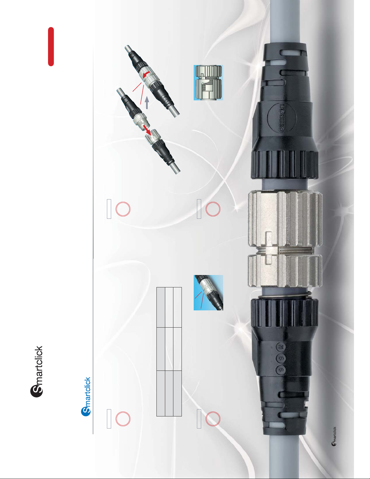
1/8th of a turn
Click!
Insert all the
way in.
XS5
3
Problem
It's difficult to keep track of locking torque values.
Locking is done with approxi-
mately 1/8th of a turn.
The Smartclick XS5 has the industry's
shortest locking rotation of 1/8th of a
turn. There's no need to keep
track of locking torque, and
this greatly reduces time
and effort when wiring.
Solution
Screw connection
Screw connection
M12 plug connector
Plug Connector
XS5 Smartclick
Twist-and-click connection
Screw connection
The connection sometimes
vibrates loose.
A bayonet lock mechanism is used.
By using a bayonet mechanism, which is a common
locking method, the Smartclick XS5 eliminates any
concerns about loosening.
4
Solution
Problem
Click!
A simple twist is all it takes to connect the Smartclick XS5, making it an ideal next-generation M12
connector. It's also easy to introduce to existing facilities because it takes only 1/4 the time of
ordinary wiring processes, and it's compatible with conventional, screw-type connectors.
The simple, XS5 Connector is completely compatible with conventional
screw-type M12 connectors.
1
It's troublesome to screw the connectors together.
It's a twist-and-click connection.
Solution
Problem
An innovative new lock structure makes connection extremely simple. The lock
mechanism is internal, so it will no longer become jammed by sputtered fluids or
dust. Also, the use of a movable lock bolt makes it possible to connect the
Smartclick XS5 to a screw-type M12 connector.
All combinations are connectable.
XS5 Smartclick Socket
Connector
M12 socket connector
There's nothing to tell you that it's
connected.
The Smartclick XS5 "clicks"
2
Solution
Problem
to tell you it's connected.
A positive clicking feel tells you for sure that the
Connector is securely locked.
The connector solves the problems of previous screw-type connectors.
Note: is a registered trademark of the OMRON Corporation.
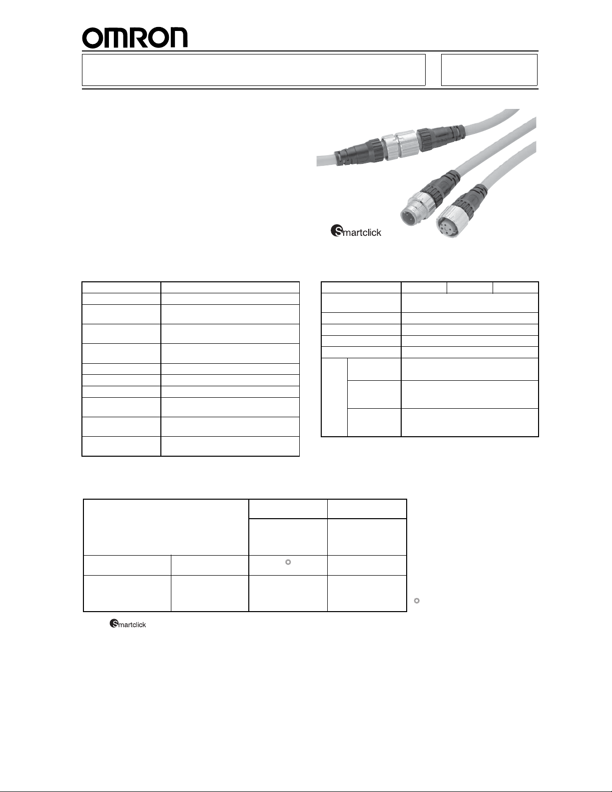
Water-resistive Smar tclick Connectors
That Reduce Installation Work
■ A newly developed lock structure that maintains
compatibility with conventional, screw-type M12
connectors.
■ Simply insert the Connectors, then turn them
approximately 1/8 of a turn to lock.
■ A positive click indicates locking.
■ Features the same degree of protection (IP6 7) as
conventional, screw-type M12 connectors.
■ A full line-up of models is planned.
■ Specifications ■ Materials and Finish
XS5Water-resistive Sensor I/O Connectors
Rated current 4 A
Rated voltage 250 VDC
Contact resistance
(connector)
Insulation resis-
tance
Dielectric strength
(connector)
Degree of protection IP67 (IEC60529)
Insertion tolerance 50 times min.
Lock strength Pulling: 100 N/15 s, Twisting: 1 N·m/15 s
Cable holding
strength
Lock operating
force
Ambient tempera-
ture range
40 m
Ω max.
(20 mV max., 100 mA max.)
1,000 M
Ω min. (at 500 VDC)
1,500 VAC for 1 min
(leakage current: 1 mA max.)
100 N/15 s (for cable diameter of 6 mm)
0.1 N·m to 0.25 N·m
Operating:
−25 to 70°C
■ Connection Combinations
OMRON model No. Smartclick Plug
Smartclick Socket
Connectors
M12 Socket Connectors
Note: is a registered trademark of the OMRON Corporation.
XS5F,
XS5W (socket side)
XS2F, XS2C,
XS2W (socket side),
XS2R (socket side),
XS2P
Connectors
XS5H,
XS5W (plug side)
❍❍
Item Model XS5F XS5H XS5W
Contacts Phosphor bronze/nickel base, 0.4-
Fixtures Nickel-plated zinc alloy
Pin Block PBT resin (UL94V-0)
Cover Polyester elastomer (UL94V-0)
O-ring Rubber
Cable Standard
cable
Vibration-
proof robot
cable
Oil-resistant
polyurethane
cable
M12 Plug
Connectors
XS2H, XS2G
XS2W (plug side),
XS2R (plug side),
XS2M
❍
gold-plating
UL AWM2464, 6-mm dia.
4 cores
× AWG20 (0.12/49)
UL AWM2464, 6-mm dia.
4 cores
× AWG200 (0.08/110)
6 dia.
4 cores
× 0.5 mm
: Connected by twisting.
❍ : Connected by screwing.
2
(0.12/45)
µm
4

Connectors Connected to Cable,
XS5W
Socket and Plug on Cable Ends
XS5W
XS5W-D421-@81-AStandard Cable
XS5W-D421-@81-FVibration-proof Robot Cable
XS5W-D421-@81-POil-resistant Polyurethane Cable
■ Dimensions
44.7
14.9 dia.
M12
Note: The cover of the Standard Cable (XS5W-D421-@81-A) is black, and the cover of the Vibration-proof Robot Cable (XS5W-D421-
@81-F) is warm gray.
L (Cable length)
6 dia.
40.7
14.9 dia.
Wiring Diagram for 4 Cores
Terminal No.
1
2
3
4
M12
Cable
Color of core
sheath
1
2
3
4
(For DC use)
■ Ordering Info rmation
Brown
White
Blue
Black
Cable type Cable connection
directions
Standard cable Straight/straight 4 1 XS5W-D421-C81-A 10
Vibration-proof
robot cable
Oil-resistant
polyurethane
cable
Note: Ask your OMRON representative about other specifications.
No. of cable
cores
Cable length
(m)
2 XS5W-D421-D81-A
3 XS5W-D421-E81-A
5 XS5W-D421-G81-A 5
10 XS5W-D421-J81-A
1 XS5W-D421-C81-F 10
2 XS5W-D421-D81-F
3 XS5W-D421-E81-F
5 XS5W-D421-G81-F 5
10 XS5W-D421-J81-F
2 XS5W-D421-D81-P 10
5 XS5W-D421-G81-P 5
10 XS5W-D421-J81-P
Model Minimum order
■ Model Number Legend
Use this model number legend to identify products from their
model number. When ordering, use a model number from the
table in Ordering Information.
XS5W - D@2@ - @@1 - @
1234
1. Type
W: Connectors connected to cable, socket and plug on
cable ends
2. AC/DC (Mating Section Form)
D: DC
3. Connector Poles
4: 4 poles
4. Contact Plating
2: 0.4-
5. Cable Connection Directions
1: Straight/straight
5 678 9
µm gold plating
6. Cable Length
A: 0.3 m G: 5 m
B: 0.5 m H: 7 m
C: 1 m J: 10 m
D: 2 m K: 15 m
E: 3 m L: 20 m
F: 4 m
7. Connections
8: A Brown, B White, C Blue, D Black (Numbers inside
circles are terminal numbers.)
8. Connectors on One End/Both Ends
1: Both ends
9. Cable Specifications
A: Standard cable
F: Vibration-proof robot cable
P: Oil-resistant polyurethane cable
5

Connector Connected to Cable,
Socket on One Cable End
XS5F
XS5F-D421-@80-A Standard Cable
XS5F-D421-@80-F Vibration-proof Robot Cable
XS5F-D421-@80-P Oil-resistant Polyurethane Cable
■ Dimensions
L (Cable length)
40.7
14.9 dia.
M12
Note: The cover of the Standard Cable (XS5F-D421-@81-A) is black, and the cover of the Vibration-proof Robot Cable (XS5F-D421-@81-
F) is warm gray.
6 dia.
30 5
50
Wiring Diagram for 4 Cores
Terminal No.
1
2
3
4
Cable
Color of core sheath
Brown
White
Blue
Black
(For DC use)
■ Ordering Info rmation
Cable type Cable connection
direction
Standard cable Straight 4 1 XS5F-D421-C80-A 10
Vibration-proof
robot cable
Oil-resistant
polyurethane
cable
Note: Ask your OMRON representative about other specifications.
No. of cable
cores
Cable length
(m)
2 XS5F-D421-D80-A
3 XS5F-D421-E80-A
5 XS5F-D421-G80-A 5
10 XS5F-D421-J80-A
1 XS5F-D421-C80-F 10
2 XS5F-D421-D80-F
3 XS5F-D421-E80-F
5 XS5F-D421-G80-F 5
10 XS5F-D421-J80-F
2 XS5F-D421-D80-P 10
5 XS5F-D421-G80-P 5
10 XS5F-D421-J80-P
Model Minimum order
■ Model Number Legend
Use this model number legend to identify products from their
model number. When ordering, use a model number from the
table in Ordering Information.
XS5F - @@2@ - @@0 - @
1234
1. Type
F: Connector connected to cable, socket on one cable
2. AC/DC (Mating Section Form)
D: DC
3. Connector Poles
4: 4 poles
4. Contact Plating
2: 0.4-
5. Cable Connection Direction
1: Straight
6
5 678 9
end
µm gold plating
6. Cable Length
A: 0.3 m G: 5 m
B: 0.5 m H: 7 m
C: 1 m J: 10 m
D: 2 m K: 15 m
E: 3 m L: 20 m
F: 4 m
7. Connections
8: A Brown, B White, C Blue, D Black (Numbers inside
circles are terminal numbers.)
8. Connectors on One End/Both Ends
0: One end
9. Cable Specification
A: Standard cable
F: Vibration-proof robot cable
P: Oil-resistant polyurethane cable

Connector Connected to Cable,
Plug on One Cable End
XS5H
XS5H-D421-@80-A Standard Cable
XS5H-D421-@80-F Vibration-proof Robot Cable
XS5H-D421-@80-P Oil-resistant Polyurethane Cable
■ Dimensions
L (Cable length)
44.7
Note: The cover of the Standard Cable (XS5W-D421-@81-A) is black, and the cover of the Vibration-proof Robot Cable (XS5W-D421-
@81-F) is warm gray.
6 dia.
30 5
50
Wiring Diagram for 4 Cores
Terminal No.
1
2
3
4
Cable
Color of core sheath
Brown
White
Blue
Black
(For DC use)
■ Ordering Info rmation
Cable type Cable connection
direction
Standard cable Straight 4 0.3 XS5H-D421-A80-A 10
Vibration-proof
robot cable
Oil-resistant
polyurethane
cable
Note: Ask your OMRON representative about other specifications.
No. of cable
cores
Cable length
(m)
1 XS5H-D421-C80-A
2 XS5H-D421-D80-A
5 XS5H-D421-G80-A 5
0.3 XS5H-D421-A80-F 10
1 XS5H-D421-C80-F
2 XS5H-D421-D80-F
5 XS5H-D421-G80-F 5
0.3 XS5H-D421-A80-P 10
2 XS5H-D421-D80-P 5
5 XS5H-D421-G80-P
Model Minimum order
■ Model Number Legend
Use this model number legend to identify products from their
model number. When ordering, use a model number from the
table in Ordering Information.
XS5H - @@21 - @@0 - @
1234
1. Type
F: Connector connected to cable, plug on one cable end
2. AC/DC (Mating Section Form)
D: DC
3. Connector Poles
4: 4 poles
4. Contact Plating
2: 0.4-
5. Cable Connection Direction
1: Straight
5 678 9
µm gold plating
6. Cable Length
A: 0.3 m G: 5 m
B: 0.5 m H: 7 m
C: 1 m J: 10 m
D: 2 m K: 15 m
E: 3 m L: 20 m
F: 4 m
7. Connections
8: A Brown, B White, C Blue, D Black (Numbers inside
circles are terminal numbers)
8. Connectors on One End/Both Ends
0: One end
9. Cable Specifications
A: Standard cable
F: Vibration-proof robot cable
P: Oil-resistant polyurethane cable
7

■ Connecting the Smartclick XS5
1. Connecting the Smartclick XS5 Plug and Socket
• Align the projection on the plug cover with the polarity key on
the socket, then insert the plug all the way in.
Polarity key
Protrusion on
cover aligns with
polarity key.
• Hold the knurled socket grip, then insert the projection on the
plug into the groove of the socket.
■ Safety Precau tio n s
Precautions for Correct Use
Do not use the Connectors in an atmosphere or environment that
exceeds the specifications.
Connector Connection and Disconnection
• When connecting or disconnecting Connectors, be sure to hold the
Connectors by hand.
• Do not hold the cable when disconnecting Connectors.
• When joining Connectors, be sure to inser t the plug all the way to
the back of the socket before attempting to lock the Connectors.
• Do not use tools of any sor t to join the Connectors. Always use
your hands. Pliers or other tools may damage the Connectors.
• When joining the Connectors to XS2 or other M12 Connectors,
tighten the lock by hand to a torque of 0.39 to 0.49 N
⋅m.
• Turn the knurled grips of the socket clockwise approximately 45
degrees in respect to the plug. A click will indicate that the Connectors are locked. The locking condition can also be confirmed
by the alignment marks on the plug and socket.
Wiring
• Always confirm wiring diagrams before wiring sensors, limit
switches, or other devices.
• Lay the cables so that external force is not applied to the Connectors. Otherwise, the degree of protection (IP67) may not be
achieved.
Degree of Protection
Alignment marks
2. Connecting the Smartclick XS5 and XS2
• Align the projection on the plug cover with the polarity key on
the socket, then insert the plug all the way in.
• In the same way as when connecting two XS2 Connectors,
screw the knurled grip in the clockwise direction.
• Use your fingers to tighten the Connectors sufficiently.
• The application examples provided in this catalog are for reference only. Check functions and safety of the equipment before use.
• Never use the products for any application requiring special safety requir em ent s, such as nuclea r en ergy control syst ems, railro ad s ystem s, aviation syste ms,
medical equipment, amu sement mac hines, vehicles, safety equipm ent, or othe r applica tion involving ser ious risk to life or proper ty, without ensuring that the
system as a whole has been desig ned to address the r isks, and that the OMRON products ar e properly rated and installed for the intended use within the
overall equipment or system.
• The degree of protection of Connectors (IP67) is not for a fully
watertight structure. Do not the Connectors underwater.
• Do not step on or place any objects on the Connectors. Doing so
may damage the Connectors.
ALL DIMENSIONS SHOWN ARE IN MILLIMETERS.
To convert millimeters into inches, multiply by 0.03937. To convert grams into ounces, multiply by 0.03527.
Cat. No. G016-E1-01
In the interest of product improvement, specifications are subjec t to c hange witho ut notic e.
OMRON Corporation
Electronic Components Company
Connector Division
Sakado 3-2-1, Takatsu-ku, Kawasaki-city,
Kanagawa, 213-0012 Japan
Tel: (81)44-812-3432/Fax: (81)44-812-3447
Regional Headquarters
OMRON EURO P E B.V.
Sensor Business Unit,
Carl-Benz-Str. 4, D-71154 Nufringen,
Germany
Tel: (49)7032-811-0/Fax: (49)7032-811-199
OMRON ELECTRONICS LLC
1 East Commerce Drive, Schaumburg, IL 60173
U.S.A.
Tel: (1)847-843-7900/Fax: (1)847-843-8568
OMRON ASIA PACIFIC PTE. LTD.
83 Clemenceau Avenue,
#11-01, UE Square,
239920 Singapore
Tel: (65)6835-3011/Fax: (65)6835-2711
OMRON (CHINA) CO., LTD.
Room 2211, Bank of China Tower,
200 Yin Cheng Road (M),
Shanghai, 200120 China
Tel: (86)21-5037-2222/Fax: (86)21-5037-2200
Printed in Japan
0307-3M (0307) (C)
 Loading...