

Page 1

Cat. No. Z291-E1-0
FZ3
Xpectia Series
Vision Sensor
Processing Items List
USERS MANUAL
Page 2

Introduction
Thank you for purchasing the FZ3 Series.
This manual provides information regarding functions, performance and operating methods that
are required for using the FZ3 Series.
When using the FZ3 Series, be sure to observe the following:
• The FZ3 Series must be operated by personnel knowledgeable in electrical engineering.
• To ensure correct use, please read this manual thoroughly to deepen your understanding of the
product.
• Please keep this manual in a safe place so that it can be referred to whenever necessary.
Page 3

Contents
1. Input image
Camera Image Input ………………………………………………………………………………………12
Settings Flow (Camera Image Input) …………………………………………………………………12
Camera Selection (Camera Image Input) ……………………………………………………………13
Camera Settings (Camera Image Input) ………………………………………………………………14
Screen Adjustment Settings (Camera Image Input) …………………………………………………18
White Balance (Camera Image Input) …………………………………………………………………23
Calibration (Camera Image Input)………………………………………………………………………24
Additional Explanation (Camera Image Input) ………………………………………………………31
Camera Image Input HDR+ ………………………………………………………………………………32
Settings Flow (Camera Image Input HDR+) …………………………………………………………32
HDR Settings (Camera Image Input HDR+) …………………………………………………………33
Bright Adjust Setting (Camera Image Input HDR+) …………………………………………………36
Camera Switching …………………………………………………………………………………………38
Camera Selection (Camera Switching) ………………………………………………………………38
Additional Explanation (Camera Switching) …………………………………………………………38
Measurement Image Switching ……………………………………………………………………………40
Parameter Settings (Measurement Image Switching) ………………………………………………40
2. Measurement
Search ………………………………………………………………………………………………………42
Settings Flow (Search) …………………………………………………………………………………42
Model Registration (Search) ……………………………………………………………………………43
Region Setting (Search) …………………………………………………………………………………46
Detection Point (Search)…………………………………………………………………………………47
Reference Position (Search) ……………………………………………………………………………47
Measurement Parameters (Search) ……………………………………………………………………48
Output Parameters (Search) ……………………………………………………………………………50
Key Points for Test Measurement and Adjustment (Search) ………………………………………50
Measurement Results for Which Output Is Possible (Search) ………………………………………52
Flexible Search………………………………………………………………………………………………53
Settings Flow (Flexible Search)…………………………………………………………………………53
Model Registration (Flexible Search) …………………………………………………………………54
Region Setting (Flexible Search) ………………………………………………………………………57
Measurement Parameters (Flexible Search) …………………………………………………………57
Output Parameters (Flexible Search) …………………………………………………………………59
Key Points for Test Measurement and Adjustment (Flexible Search)………………………………59
Measurement Results for Which Output Is Possible (Flexible Search) ……………………………61
Sensitive Search ……………………………………………………………………………………………62
Settings Flow (Sensitive Search) ………………………………………………………………………62
Model Registration (Sensitive Search)…………………………………………………………………63
Region Setting (Sensitive Search) ……………………………………………………………………66
Detection Point (Sensitive Search) ……………………………………………………………………67
Reference Position (Sensitive Search)…………………………………………………………………67
Measurement Parameters (Sensitive Search) ………………………………………………………68
Output Parameters (Sensitive Search)…………………………………………………………………69
………………………………………………………………………………………………11
……………………………………………………………………………………………41
FZ3 Processing Items List Manual
1
Page 4

Key Points for Test Measurement and Adjustment (Sensitive Search) ……………………………70
Measurement Results for Which Output Is Possible (Sensitive Search) …………………………72
ECM Search …………………………………………………………………………………………………73
Settings Flow (ECM Search) ……………………………………………………………………………73
Model Registration (ECM Search) ……………………………………………………………………74
Error Model Registration (ECM Search) ………………………………………………………………78
Region Setting (ECM Search) …………………………………………………………………………78
Detection Point (ECM Search) …………………………………………………………………………78
Reference Position (ECM Search) ……………………………………………………………………79
Measurement Parameters (ECM Search) ……………………………………………………………80
Output Parameters (ECM Search) ……………………………………………………………………81
Key Points for Test Measurement and Adjustment (ECM Search) …………………………………82
When Using Measurement Results Externally (ECM Search) ………………………………………83
EC Circle Search ……………………………………………………………………………………………84
Settings Flow (EC Circle Search) ………………………………………………………………………84
Circle Setting (EC Circle Search) ………………………………………………………………………85
Region Setting (EC Circle Search) ……………………………………………………………………86
Reference Position (EC Circle Search) ………………………………………………………………87
Color Specification (EC Circle Search)…………………………………………………………………88
Measurement Parameters (EC Circle Search) ………………………………………………………89
Output Parameters (EC Circle Search) ………………………………………………………………91
Key Points for Test Measurement and Adjustment (EC Circle Search) ……………………………92
Measurement Results for Which Output Is Possible (EC Circle Search) …………………………93
Shape Search+ ……………………………………………………………………………………………94
Settings Flow (Shape Search+)…………………………………………………………………………95
Model Registration (Shape Search+) …………………………………………………………………95
Region Setting (Shape Search+) ………………………………………………………………………97
Detection Point (Shape Search+) ………………………………………………………………………97
Reference Position (Shape Search+) …………………………………………………………………98
Measurement Parameters (Shape Search+) …………………………………………………………99
Output Parameters (Shape Search+)…………………………………………………………………100
Key Points for Test Measurement and Adjustment (Shape Search+) ……………………………101
Measurement Results for Which Output Is Possible (Shape Search+) …………………………102
Classification ………………………………………………………………………………………………104
Settings Flow (Classification) …………………………………………………………………………104
Model Registration (Classification) ……………………………………………………………………105
Region Setting (Classification) ………………………………………………………………………109
Measurement Parameters (Classification) …………………………………………………………110
Output Parameters (Classification)……………………………………………………………………111
Key Points for Test Measurement and Adjustment (Classification) ………………………………111
Measurement Results for Which Output Is Possible (Classification)………………………………113
Edge Position ………………………………………………………………………………………………114
Settings Flow (Edge Position) …………………………………………………………………………114
Region Setting (Edge Position) ………………………………………………………………………115
Edge Color Specification - For Color Cameras Only (Edge Position) ……………………………117
Reference Position (Edge Position) …………………………………………………………………118
Measurement Parameters (Edge Position) …………………………………………………………119
Output Parameters (Edge Position) …………………………………………………………………122
Key Points for Test Measurement and Adjustment (Edge Position) ………………………………123
2
FZ3 Processing Items List Manual
Page 5

Measurement Results for Which Output Is Possible (Edge Position) ……………………………123
Edge Pitch …………………………………………………………………………………………………124
Settings Flow (Edge Pitch) ……………………………………………………………………………124
Region Setting (Edge Pitch)……………………………………………………………………………125
Edge Color Specification - For Color Cameras Only (Edge Pitch)…………………………………126
Measurement Parameters (Edge Pitch)………………………………………………………………127
Output Parameters (Edge Pitch)………………………………………………………………………129
Key Points for Test Measurement and Adjustment (Edge Pitch) …………………………………130
Measurement Results for Which Output Is Possible (Edge Pitch)…………………………………131
Scan Edge Position ………………………………………………………………………………………132
Settings Flow (Scan Edge Position) …………………………………………………………………132
Region Setting (Scan Edge Position)…………………………………………………………………133
Edge Color Specification - For Color Cameras Only (Scan Edge Position) ………………………135
Reference Position (Scan Edge Position) ……………………………………………………………136
Measurement Parameters (Scan Edge Position)……………………………………………………137
Judgment Conditions (Scan Edge Position) …………………………………………………………140
Output Parameters (Scan Edge Position) ……………………………………………………………142
Key Points for Test Measurement and Adjustment (Scan Edge Position) ………………………143
Measurement Results for Which Output Is Possible (Scan Edge Position) ………………………144
Scan Edge Width …………………………………………………………………………………………145
Settings Flow (Scan Edge Width) ……………………………………………………………………145
Region Setting (Scan Edge Width)……………………………………………………………………146
Edge Color Specification - For Color Cameras Only (Scan Edge Width) …………………………148
Measurement Parameters (Scan Edge Width)………………………………………………………149
Judgement Conditions (Scan Edge Width) …………………………………………………………151
Output Parameters (Scan Edge Width) ………………………………………………………………152
Key Points for Test Measurement and Adjustment (Scan Edge Width) …………………………153
Measurement Results for Which Output Is Possible (Scan Edge Width) …………………………153
Color Data …………………………………………………………………………………………………154
Settings Flow (Color Data) ……………………………………………………………………………154
Region Setting (Color Data)……………………………………………………………………………155
Measurement Parameters (Color Data)………………………………………………………………156
Output Parameters (Color Data) ………………………………………………………………………158
Key Points for Test Measurement and Adjustment (Color Data) …………………………………158
Measurement Results for Which Output Is Possible (Color Data)…………………………………159
Gravity and Area …………………………………………………………………………………………160
Settings Flow (Gravity and Area) ……………………………………………………………………160
Color Specification (Gravity and Area) ………………………………………………………………162
Binarization (Gravity and Area) ………………………………………………………………………164
Region Setting (Gravity and Area) ……………………………………………………………………165
Reference Position (Gravity and Area) ………………………………………………………………166
Measurement Parameters (Gravity and Area) ………………………………………………………167
Output Parameters (Gravity and Area) ………………………………………………………………169
Key Points for Test Measurement and Adjustment (Gravity and Area) …………………………170
Measurement Results for Which Output Is Possible (Gravity and Area) …………………………170
Labeling ……………………………………………………………………………………………………172
Settings Flow (Labeling) ………………………………………………………………………………172
Color Specification (Labeling) …………………………………………………………………………173
Binarization (Labeling) …………………………………………………………………………………176
FZ3 Processing Items List Manual
3
Page 6

Region Setting (Labeling)………………………………………………………………………………177
Reference Position (Labeling) …………………………………………………………………………178
Measurement Parameters (Labeling)…………………………………………………………………179
Judgement Conditions (Labeling) ……………………………………………………………………182
Output Parameters (Labeling) …………………………………………………………………………183
Key Points for Test Measurement and Adjustment (Labeling) ……………………………………184
Measurement Results for Which Output Is Possible (Labeling)……………………………………184
Label Data …………………………………………………………………………………………………186
Settings Flow (Label Data) ……………………………………………………………………………187
Setting (Label Data) ……………………………………………………………………………………187
Output Parameters (Label Data)………………………………………………………………………188
Test Measurement (Label Data) ………………………………………………………………………189
Measurement Results for Which Output Is Possible (Label Data)…………………………………189
Labeling+ …………………………………………………………………………………………………190
Settings Flow (Labeling+)………………………………………………………………………………190
Color Specification (Labeling+) ………………………………………………………………………192
Binarization (Labeling+) ………………………………………………………………………………194
Region Setting (Labeling+) ……………………………………………………………………………196
Reference Position (Labeling+) ………………………………………………………………………197
Extraction Conditions (Labeling+) ……………………………………………………………………198
Measurement Parameters (Labeling+) ………………………………………………………………200
Judgement Conditions (Labeling+)……………………………………………………………………204
Output Parameters (Labeling+) ………………………………………………………………………205
Key Points for Test Measurement and Adjustment (Labeling+)……………………………………206
Measurement Results for Which Output Is Possible (Labeling+) …………………………………207
Defect ………………………………………………………………………………………………………209
Settings Flow (Defect) …………………………………………………………………………………209
Region Setting (Defect) ………………………………………………………………………………210
Measurement Parameters (Defect) …………………………………………………………………211
Output Parameters (Defect)……………………………………………………………………………215
Key Points for Test Measurement and Adjustment (Defect) ………………………………………215
Measurement Results for Which Output Is Possible (Defect)………………………………………216
Precise Defect ……………………………………………………………………………………………217
Settings Flow (Precise Defect) ………………………………………………………………………217
Region Setting (Precise Defect) ………………………………………………………………………218
Measurement Parameters (Precise Defect) …………………………………………………………219
Output Parameters (Precise Defect) …………………………………………………………………223
Key Points for Test Measurement and Adjustment (Precise Defect) ……………………………223
Measurement Results for Which Output Is Possible (Precise Defect) ……………………………224
Fine Matching………………………………………………………………………………………………225
Settings Flow (Fine Matching)…………………………………………………………………………225
Model Registration (Fine Matching) …………………………………………………………………227
Difference Image Display (Fine Matching)……………………………………………………………228
Measurement Parameters (Fine Matching) …………………………………………………………230
Output Parameters (Fine Matching) …………………………………………………………………233
Key Points for Test Measurement and Adjustment (Fine Matching) ………………………………234
Measurement Results for Which Output Is Possible (Fine Matching) ……………………………235
Character Inspection………………………………………………………………………………………236
Settings Flow (Character Inspection) …………………………………………………………………236
4
FZ3 Processing Items List Manual
Page 7

Dictionary Parameters (Character Inspection) ………………………………………………………237
Region Setting (Character Inspection) ………………………………………………………………238
Measurement Parameters (Character Inspection) …………………………………………………238
Output Parameters (Character Inspection) …………………………………………………………240
Key Points for Test Measurement and Adjustment (Character Inspection) ………………………241
Measurement Results for Which Output Is Possible (Character Inspection) ……………………242
Date Verification …………………………………………………………………………………………244
Settings Flow (Date Verification)………………………………………………………………………244
Verification Parameters (Date Verification) …………………………………………………………245
Date Parameters (Date Verification) …………………………………………………………………247
Code Parameters (Date Verification) …………………………………………………………………248
Output Parameters (Date Verification) ………………………………………………………………251
Test Measurement (Date Verification) ………………………………………………………………252
Measurement Results for Which Output Is Possible (Date Verification) …………………………252
Model Dictionary …………………………………………………………………………………………253
Settings Flow (Model Dictionary) ……………………………………………………………………253
Model Registration (Model Dictionary) ………………………………………………………………254
Measurement Parameters (Model Dictionary) ………………………………………………………257
Model Automatic Registration (Model Dictionary) …………………………………………………258
Key Points for Test Measurement and Adjustment (Model Dictionary)……………………………260
Measurement Results for Which Output Is Possible (Model Dictionary) …………………………260
Barcode+……………………………………………………………………………………………………261
Settings Flow (Barcode+)………………………………………………………………………………261
Region Setting (Barcode+) ……………………………………………………………………………262
Measurement Parameters (Barcodes+)………………………………………………………………262
Results Settings (Barcode+) …………………………………………………………………………265
Output Parameters (Barcode+) ………………………………………………………………………265
Key Points for Test Measurement and Adjustment (Barcode+)……………………………………266
Measurement Results for Which Output Is Possible (Barcodes+)…………………………………266
2D Code+ …………………………………………………………………………………………………268
Settings Flow (2D Code+) ……………………………………………………………………………268
Region Setting (2D Code+) ……………………………………………………………………………269
Measurement Parameters (2D Code+) ………………………………………………………………269
Results Settings (2D Code+) …………………………………………………………………………271
Output Parameters (2D Code+) ………………………………………………………………………271
Key Points for Test Measurement and Adjustment (2D Code+) …………………………………272
Measurement Results for Which Output Is Possible (2D Codes+) ………………………………273
Circle Angle ………………………………………………………………………………………………275
Settings Flow (Circle Angle)……………………………………………………………………………276
Region Setting (Circle Angle) …………………………………………………………………………277
Output Parameters (Circle Angle) ……………………………………………………………………279
Key Points for Test Measurement and Adjustment (Circle Angle)…………………………………279
Measurement Results for Which Output Is Possible (Circle Angle) ………………………………280
3. Compensate image
Position Compensation……………………………………………………………………………………282
Region Compensation (Position Compensation) ……………………………………………………283
Scroll Method (Position Compensation)………………………………………………………………283
Measurement Results for Which Output Is Possible (Position Compensation) …………………285
FZ3 Processing Items List Manual
…………………………………………………………………………………281
5
Page 8

Trapezoidal Correction+ …………………………………………………………………………………286
Conversion Method (Trapezoidal Correction+)………………………………………………………286
Region Setting (Trapezoidal Correction+) ……………………………………………………………292
Key Points for Test Measurement and Adjustment (Trapezoidal Correction+) …………………293
Measurement Results for Which Output Is Possible (Trapezoidal Correction+) …………………293
Filtering ……………………………………………………………………………………………………294
Filtering Parameters (Filtering) ………………………………………………………………………294
Region Setting (Filtering) ………………………………………………………………………………298
Background Suppression …………………………………………………………………………………299
Filter Setting (Background Suppression) ……………………………………………………………299
Region Setting (Background Suppression) …………………………………………………………301
Measurement Results for Which Output Is Possible (Background Suppression) ………………301
Color Gray Filter……………………………………………………………………………………………302
Filter Setting (Color Gray Filter) ………………………………………………………………………302
Extract Color Filter…………………………………………………………………………………………306
Color Specification (Extract Color Filter) ……………………………………………………………306
Region Setting (Extract Color Filter) …………………………………………………………………309
Output Image (Extract Color Filter)……………………………………………………………………309
Measurement Results for Which Output Is Possible (Extract Color Filter) ………………………310
Anti Color Shading…………………………………………………………………………………………311
Filter Setting (Anti Color Shading) ……………………………………………………………………311
Region Setting (Anti Color Shading) …………………………………………………………………313
Key Points for Test Measurement and Adjustment (Anti Color Shading) …………………………313
Measurement Results for Which Output Is Possible (Anti Color Shading) ………………………313
Stripes Removal Filter+ …………………………………………………………………………………314
Filter Setting (Stripes Removal Filter+) ………………………………………………………………314
Region Setting (Stripes Removal Filter+) ……………………………………………………………316
Halation Cut+ ………………………………………………………………………………………………317
Filter Setting (Halation Cut+) …………………………………………………………………………317
Measurement Results for Which Output Is Possible (Halation Cut+) ……………………………319
Panorama+ …………………………………………………………………………………………………320
Camera Placement (Panorama+) ……………………………………………………………………322
Image Combination (Panorama+) ……………………………………………………………………324
Measurement Results for Which Output Is Possible (Panorama+) ………………………………325
Polar Transformation ……………………………………………………………………………………326
Region Setting (Polar Transformation) ………………………………………………………………326
Measurement Results for Which Output Is Possible (Polar Transformation) ……………………328
4. Support Inspection and Measurement
Calculation …………………………………………………………………………………………………330
Settings (Calculation) …………………………………………………………………………………330
Output Parameters (Calculation)………………………………………………………………………332
Layout of Setting Expression Window ………………………………………………………………333
Expression Usage Examples …………………………………………………………………………336
Key Points for Test Measurement and Adjustment (Calculation) …………………………………339
Measurement Results for Which Output Is Possible (Calculation) ………………………………340
Line Regression……………………………………………………………………………………………341
Function Selection (Line Regression) ………………………………………………………………342
Line 0 (Line Regression) ………………………………………………………………………………342
6
………………………………………………………329
FZ3 Processing Items List Manual
Page 9

Line 1 (Line Regression) ………………………………………………………………………………344
Point (Line Regression) ………………………………………………………………………………344
Key Points for Test Measurement and Adjustment (Line Regression) ……………………………344
Measurement Results for Which Output Is Possible (Line Regression) …………………………345
Circle Regression …………………………………………………………………………………………346
Parameter Settings (Circle Regression) ……………………………………………………………346
Key Points for Test Measurement and Adjustment (Circle Regression) …………………………348
Measurement Results for Which Output Is Possible (Circle Regression)…………………………348
Calibration+ ………………………………………………………………………………………………349
Calibration (Calibration+) ………………………………………………………………………………349
Measurement Results for Which Output Is Possible (Calibration+) ………………………………353
Set Unit Data ………………………………………………………………………………………………354
Parameter Settings (Set Unit Data) …………………………………………………………………354
Measurement Results for Which Output Is Possible (Set Unit Data) ……………………………355
Get Unit Data ………………………………………………………………………………………………356
Parameter Settings (Get Unit Data) …………………………………………………………………356
Measurement Results for Which Output Is Possible (Get Unit Data) ……………………………357
Set Unit Figure ……………………………………………………………………………………………358
Parameter Settings (Set Unit Figure) …………………………………………………………………358
Key Points for Test Measurement and Adjustment (Set Unit Figure) ……………………………362
Measurement Results for Which Output Is Possible (Set Unit Figure) ……………………………362
Get Unit Figure ……………………………………………………………………………………………363
Parameter Settings (Get Unit Figure)…………………………………………………………………363
Key Points for Test Measurement and Adjustment (Get Unit Figure) ……………………………363
Measurement Results for Which Output Is Possible (Get Unit Figure) ……………………………364
Trend Monitor………………………………………………………………………………………………366
Measurement Value (Trend Monitor) …………………………………………………………………367
Display Range (Trend Monitor) ………………………………………………………………………367
Judgement Conditions (Trend Monitor) ………………………………………………………………370
Measurement History Display (Trend Monitor) ………………………………………………………371
Data Save (Trend Monitor) ……………………………………………………………………………374
Output Parameters (Trend Monitor) …………………………………………………………………375
Key Points for Test Measurement and Adjustment (Trend Monitor) ………………………………376
Measurement Results for Which Output Is Possible (Trend Monitor) ……………………………376
Image Logging ……………………………………………………………………………………………378
Logging Conditions (Image Logging) …………………………………………………………………378
Save Destination (Image Logging) ……………………………………………………………………379
Key Points for Test Measurement and Adjustment (Image Logging) ……………………………380
Measurement Results for Which Output Is Possible (Image Logging) ……………………………380
Data Logging ………………………………………………………………………………………………381
Settings (Data Logging) ………………………………………………………………………………381
Output Format (Data Logging)…………………………………………………………………………382
Additional Explanation (Data Logging) ………………………………………………………………384
Measurement Results for Which Output Is Possible (Data Logging) ……………………………385
Elapsed Time ………………………………………………………………………………………………386
Measurement Results for Which Output Is Possible (Elapsed Time) ……………………………387
Wait …………………………………………………………………………………………………………388
Settings (Wait) …………………………………………………………………………………………388
Focus ………………………………………………………………………………………………………389
FZ3 Processing Items List Manual
7
Page 10

Measurement Parameters (Focus)……………………………………………………………………389
Region Setting (Focus)…………………………………………………………………………………390
Output Parameters (Focus) ……………………………………………………………………………391
Key Points for Test Measurement and Adjustment (Focus) ………………………………………391
Iris …………………………………………………………………………………………………………392
Measurement Parameters (Iris) ………………………………………………………………………392
Region Setting (Iris) ……………………………………………………………………………………394
Output Parameter (Iris)…………………………………………………………………………………395
Key Points for Test Measurement and Adjustment (Iris)……………………………………………395
5. Branch
Conditional Branch ………………………………………………………………………………………398
Conditional Branch ……………………………………………………………………………………399
Conditional Branch Settings Examples ………………………………………………………………400
Measurement Results for Which Output Is Possible (Conditional Branch) ………………………402
End …………………………………………………………………………………………………………403
DI Branch …………………………………………………………………………………………………405
Settings (DI Branch) ……………………………………………………………………………………405
Measurement Results for Which Output Is Possible (DI Branch) …………………………………406
6. Output result
Data Output ………………………………………………………………………………………………410
Settings (Data Output) …………………………………………………………………………………410
Output Format (Data Output) …………………………………………………………………………411
Key Points for Test Measurement and Adjustment (Data Output)…………………………………414
Measurement Results for Which Output Is Possible (Data Output) ………………………………414
Parallel Data Output ………………………………………………………………………………………415
Settings (Parallel Data Output) ………………………………………………………………………415
Output Format (Parallel Data Output) ………………………………………………………………416
Measurement Results for Which Output Is Possible (Parallel Data Output) ……………………417
Parallel Judgement Output ………………………………………………………………………………418
Settings (Parallel Judgement Output) ………………………………………………………………418
Output Parameters (Parallel Judgement Output)……………………………………………………419
Measurement Results for Which Output Is Possible (Parallel Judgement Output)………………420
……………………………………………………………………………………………………397
……………………………………………………………………………………………409
7. Display result
Result Display ……………………………………………………………………………………………422
Result Display …………………………………………………………………………………………423
Display Image File…………………………………………………………………………………………427
Select Image (Display Image File) ……………………………………………………………………427
Key Points for Test Measurement and Adjustment (Display Image File) …………………………428
Display Last NG Image ……………………………………………………………………………………429
NG Error Judgement (Display Last NG Image)………………………………………………………429
Image Saving (Display Last NG Image)………………………………………………………………431
Data Saving (Display Last NG Image) ………………………………………………………………432
Output Parameters (Display Last NG Image) ………………………………………………………432
Key Points for Test Measurement and Adjustment (Display Last NG Image) ……………………433
Measurement Results for Which Output Is Possible (Display Last NG Image) …………………433
8
……………………………………………………………………………………………421
FZ3 Processing Items List Manual
Page 11

Index
……………………………………………………………………………………………………………435
FZ3 Processing Items List Manual
9
Page 12
How This Manual Is Organized
This manual includes two manuals: the "User's Manual", which describes basic operations and settings
for vision sensors, and the "Processing Item List Manual", which describes the setting options for each
processing item.
Conventions Used in This Manual
Symbols
The symbols used in this manual have the following meanings.
Indicates relevant operational precautions that must be followed.
Indicates operation-related suggestions from OMRON.
Use of Quotation Marks and Brackets
In this manual, menus and other items are indicated as follows.
[ ] Menu Indicates the menu names or processing items shown in the menu bar.
" " Item name Indicates the item names displayed on the screen.
Version Upgrade Information (at Oct.1 2009)
The newly added functions are described here.
Revision history : FZ3-9 /H9 series (V3.0)
Newly added
function
Special function
corresponding to
FZ3-9 /H9
series
Operation modes, NG analyser, focus, iris and other functions
have been added.
※ The correspondence software is different in FZ3-3 /H3
/7 /H7 series.
The latest software is Ver2.1.
Description of newly added functions Reference in manual
Reference: "User's Manual",
"Description of M odel-specific
Functions" (p.21)
10
FZ3 Processing Items List Manual
Page 13
Input image
This chapter describes how to load images from cameras.
Reference: Camera Image Input (p.12)
Reference: Camera Image Input HDR+ (p.32)
Reference: Camera Switching (p.38)
Reference: Measurement Image Switching (p.40)
1
Input image
FZ3 Processing Items List Manual
11
Page 14
1
Input image
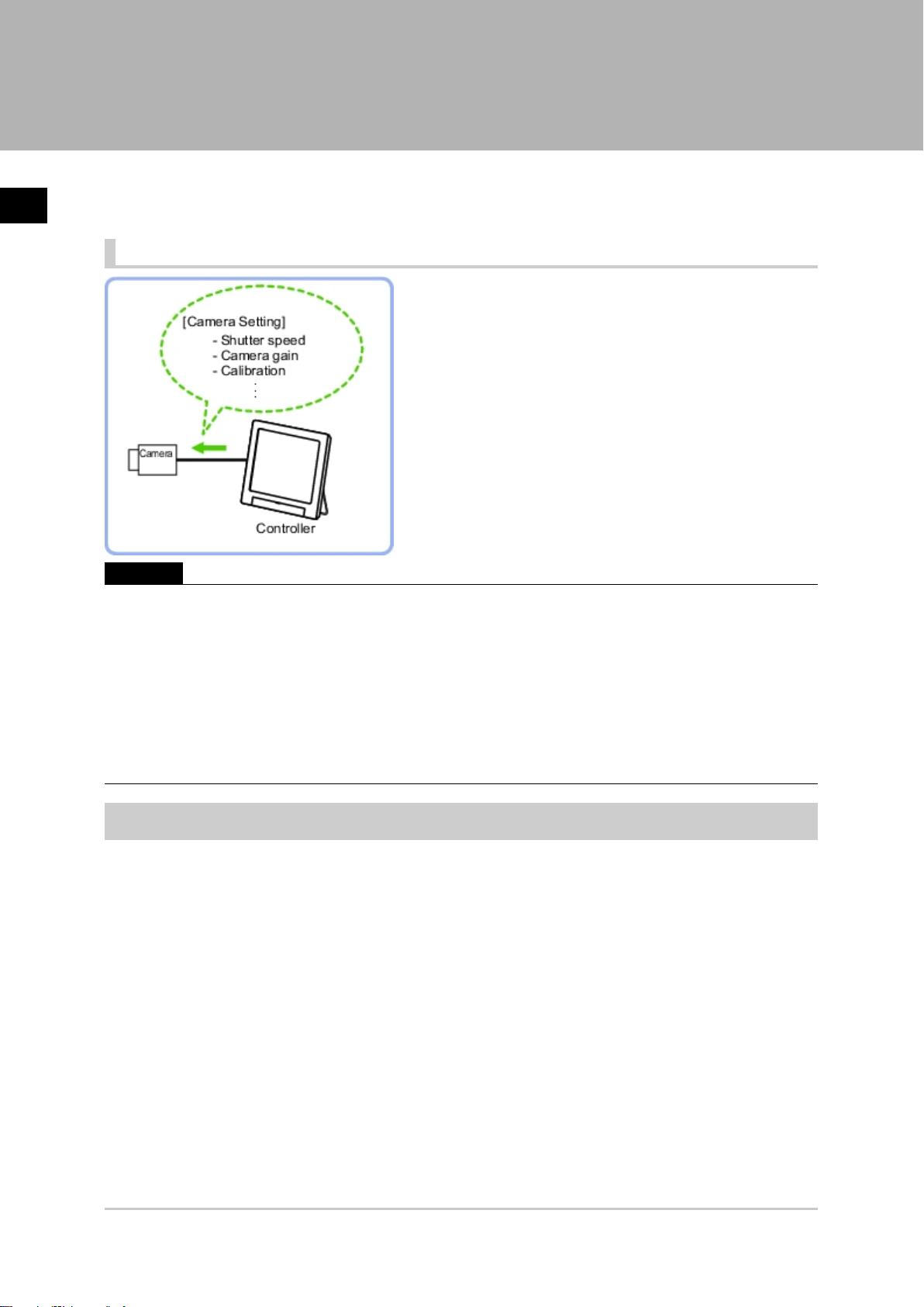
Camera Image Input
Set the conditions for loading images from the camera and for storing images of the measured
objects.This processing item must be used when measuring.
Used in the Following Case
Important
●
When using an intelligent camera FZ-SLCx or an auto-focus camera FZ-SZCx, camera image input and camera
image input HDR+ cannot be used together.
●
[Camera Image Input] is preset for Unit 0.Do not set any processing item other than camera image input
(camera image input HDR+) for Unit 0.
●
When switching from a color camera to a monochrome or switching to a camera with a different resolution,
reconfigure the settings in the following units.
●
If a camera is connected other than the one for the previous settings, the camera settings are returned to their
initial settings.
●
It is also possible to set multiple camera image input items to the flow and shoot images at different shutter
speeds. However, in this case, if the images are logged, only the last camera image input is logged.
Settings Flow (Camera Image Input)
To set camera image input, follow the steps below.
12 Camera Image Input
FZ3 Processing Items List Manual
Page 15
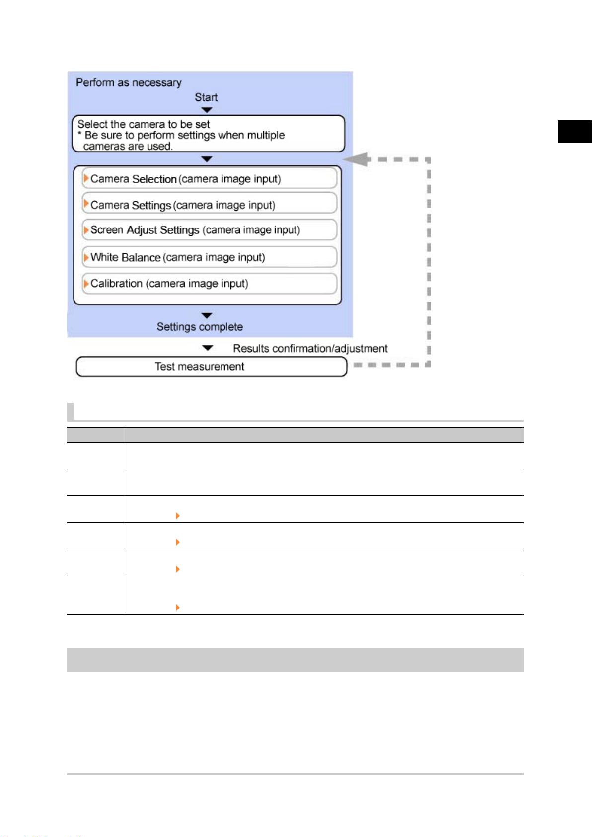
Camera Image Input Item List
1
Input image
Item Description
Camera 0 to
3
Select
camera
Camera
setting
Screen
adjust
White
balance
Calibration
Select the camera to be set.
When multiple cameras are connected, select the camera to use for measurement.
Specify the camera settings such as the shutter speed or electronic flash.
Reference: Camera Settings (Camera Image Input) (p.14)
Adjust the lighting and the lens.
Reference: Screen Adjust Settings (Camera Image Input) (p.18)
When using a color camera, adjust the white balance.
Reference: White Balance (Camera Image Input) (p.23)
Set when measurements (camera coordinate measurement values) are to be output using actual
dimensions. Select the calibration setting method and generate the calibration parameters.
Reference: Calibration (Camera Image Input) (p.24)
Camera Selection (Camera Image Input)
When multiple cameras are connected, select the camera to use for measurement.
FZ3 Processing Items List Manual
Camera Image Input 13
Page 16
1
Input image
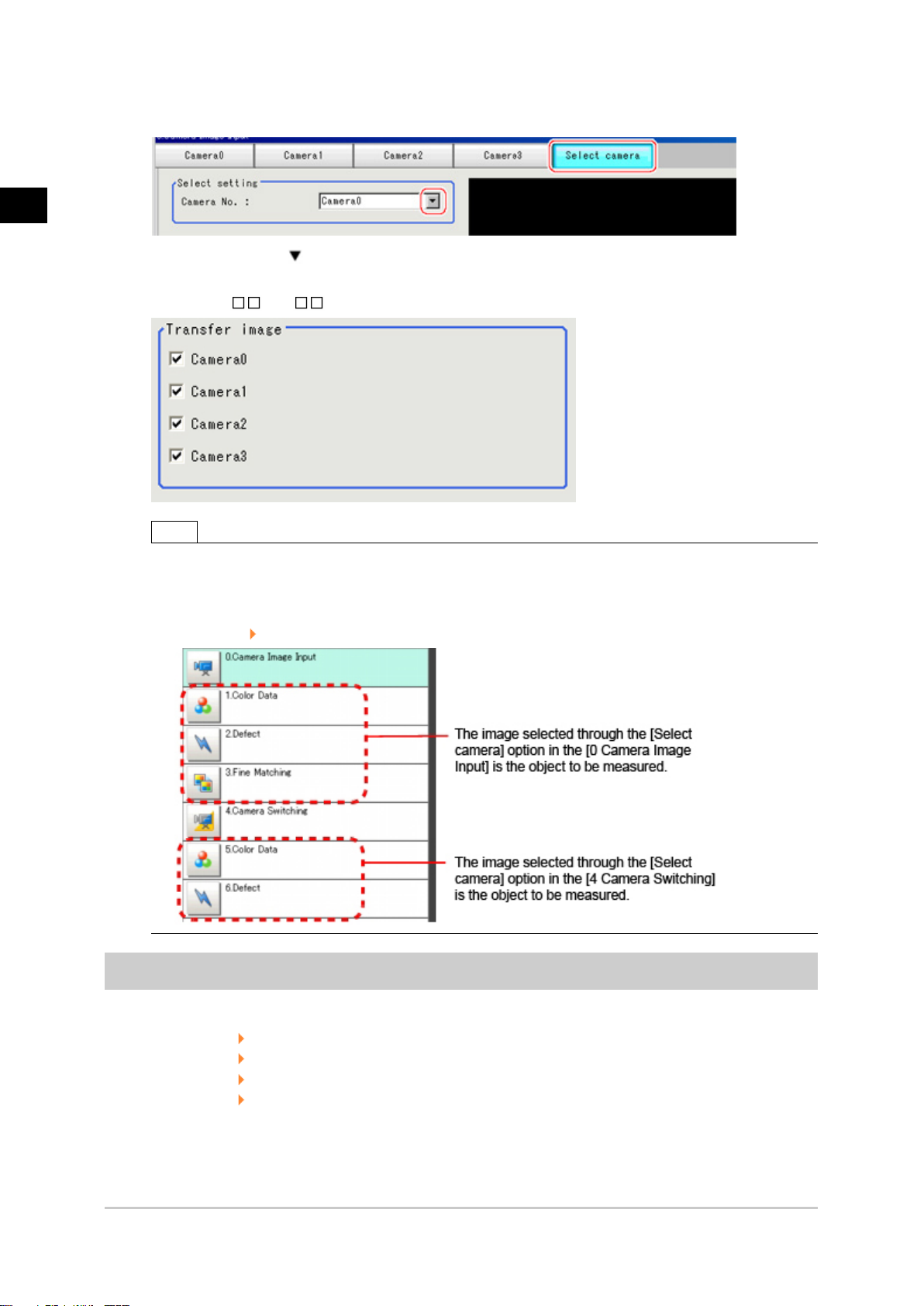
In the item tab area, tap [Select camera].
1.
Tap [Camera No.] [ ] and select the camera number.
2.
If multiple cameras are connected, whether or not to capture images from each camera can be
3.
set. (FZ3-9 /H9 only)
Note
●
The image from the camera selected in [Select camera] will be the object to be measured in the
following units.
If you need to switch the camera during the process, insert a [Camera Switching] unit in the scene and
switch the image.
Reference: Camera Switching (p.38)
Camera Settings (Camera Image Input)
Set the following photographing conditions for each camera.
●
Reference: Camera Settings (p.15)
●
Reference: Frame/Field - for Monochrome Cameras Only (p.16)
●
Reference: Number of lines to be read (p.17)
●
Reference: Electronic Flash Setting (p.18)
14 Camera Image Input
FZ3 Processing Items List Manual
Page 17
Note
●
The displayed items differ depending on the camera type and lighting mode. Perform the following procedure as
necessary in accordance with the use environment.
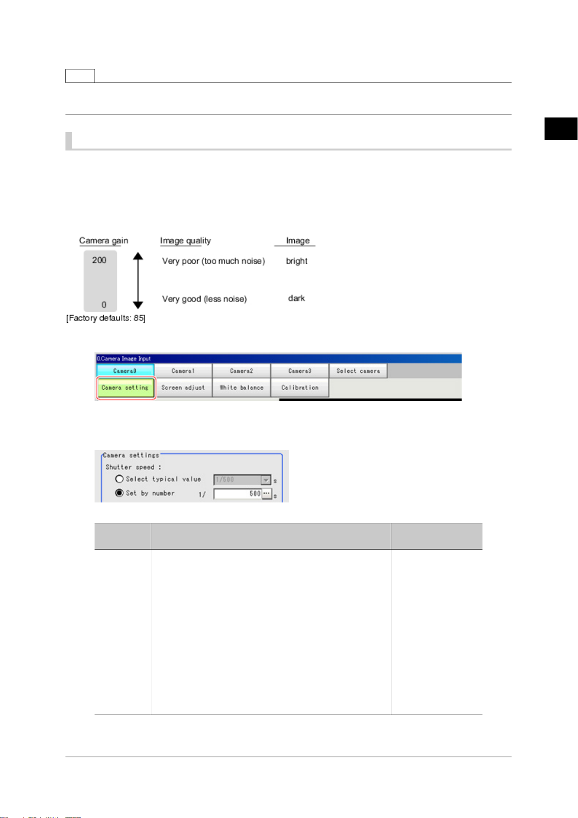
Camera Settings
Adjust the settings related to camera shutter speed and camera gain.
Select the shutter speed appropriate to the speed of the measurement object. Choose a faster shutter
speed if the measurement object is moving quickly and the image is blurred.
Adjust the camera gain when images cannot be brightened through the shutter speed, lens aperture, or
lighting conditions. Usually, the factory default value can be used.
In the Item Tab area, tap [Camera setting].
1.
1
Input image
In the "Camera settings" area, specify the shutter speed.
2.
The setting methods are to select from the options offered or to set the value directly.
Item
Shutter
speed
Typical value
●
[1/120]
(For FZ-SFx, FZ-SPx, FZ-SC2M/FZ-S2M, FZ-SC5M/
FZ-S5M)
●
1/200
●
[1/500]
(for FZ-Sx, FZ-SLC, FZ-SZC)
●
1/1000
●
1/2000
●
1/4000
●
1/8000
●
1/20000
●
Set by number
1/10 to 1/50000
Set value
[Factory default]
Description
Option values for the
shutter speed differ
depending on the
camera type.
FZ3 Processing Items List Manual
Camera Image Input 15
Page 18
1
Input image
Specify the camera gain while checking the image.
3.
Set value
[Factory default]
Description
Adjust the camera gain when the shutter speed, the
lens aperture, and lighting conditions cannot be
used to brighten the image. Usually, the factory
default value can be used.
Gain
Item
0 to 230
[50]
(For FZ-SFx, FZ-SPx,
FZ-SC2M/FZ-S2M, FZ-SC5M/
FZ-S5M)
[85]
(for FZ-Sx, FZ-SLC, FZ-SZC)
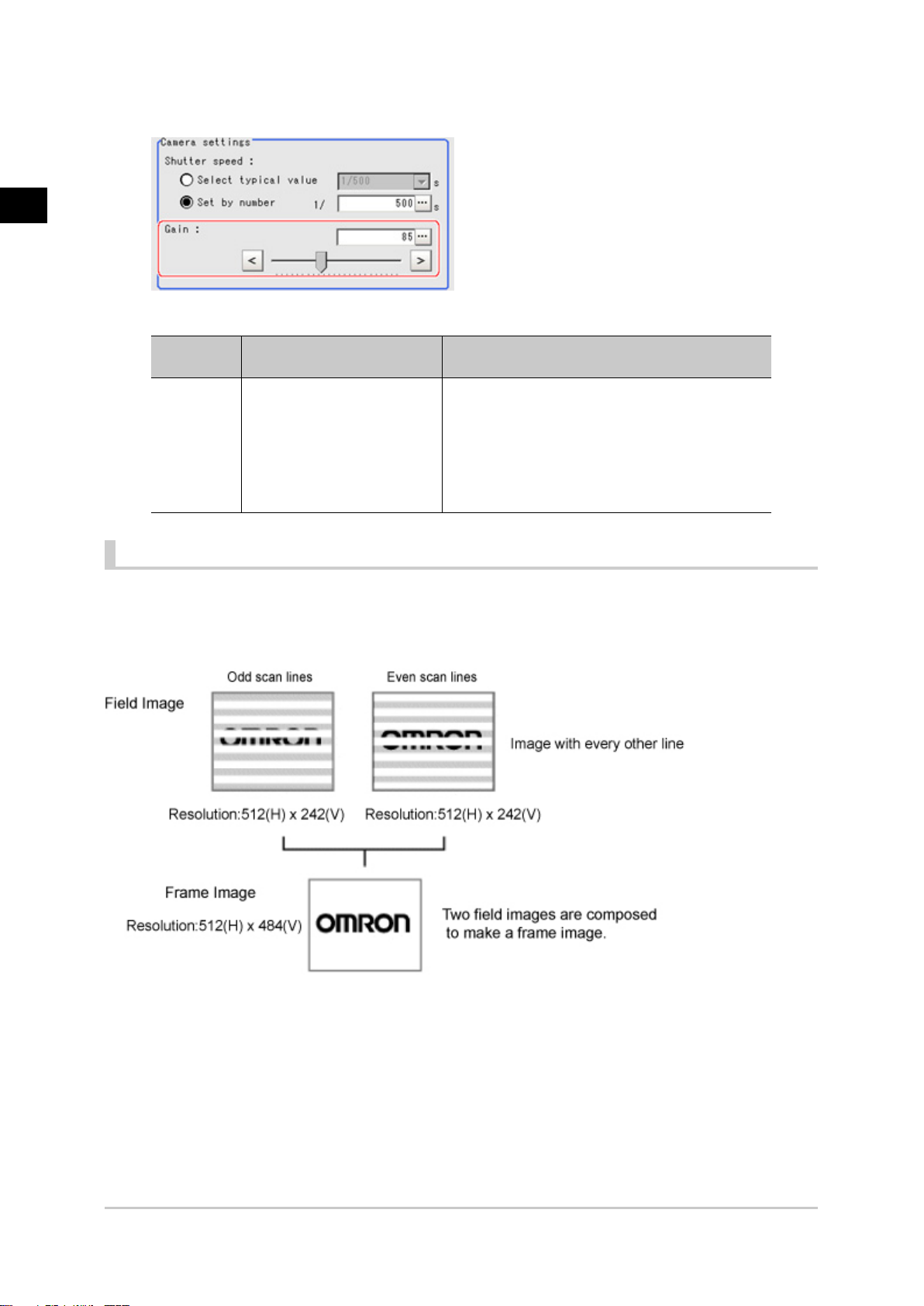
Frame/Field - for Monochrome Cameras Only
There are two methods to transfer one image from a camera to the controller: frame read and field read.
Frame read is to read all of the scanned lines of the image. The result is called a frame image. Field read
is used to read half of the interlaced scanned lines of the image. The result is called the field image.
Here, select the unit to be treated as one image.
In the Item Tab area, tap [Camera setting].
1.
In the "Frame/Field" area, select either "Frame" or "Field".
2.
16 Camera Image Input
FZ3 Processing Items List Manual
Page 19
Set value
Item
[Factory
Description
default]
[Frame] Measurements are done in frame units.
Measurements are done in field units. Select "Field" when you prefer
Frame/Field
Field
shorter image input time rather than higher accuracy.
Processing becomes faster since each image is scanned skipping
one scan line per two consecutive lines, but the measurement
precision is decreased because the vertical image resolution is lower.
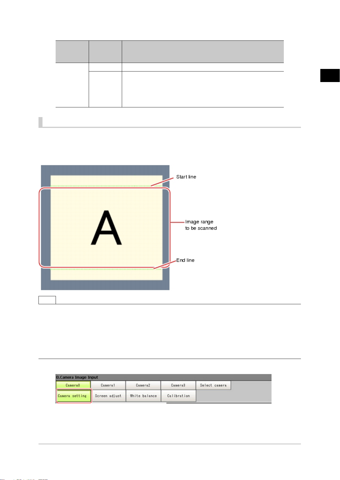
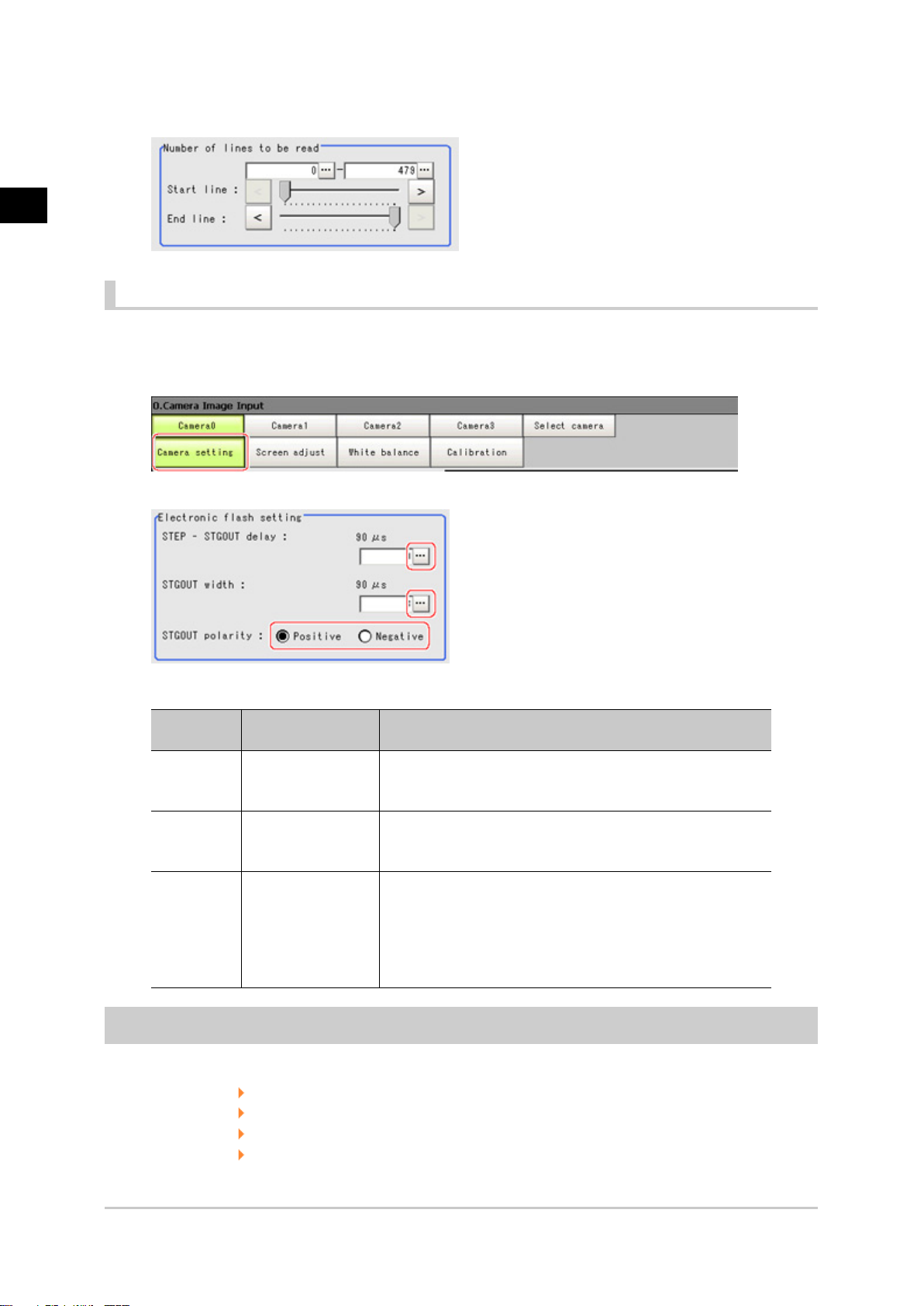
Number of lines to be read
By narrowing the image range to be loaded, the image scan time can be shortened.
Set the range taking the offset of the measurement object into consideration.
The part of the image narrowed down by the start line and the end line will be displayed in the Image
Display area of the processing item setting window or the Main screen.
1
Input image
Note
About minimum number of lines
●
The minimum number of lines (minimum number of lines between start and end lines) is 12 lines.
●
For 5 megapixel cameras, the end line is fixed to 1799.
About coordinate values
●
The coordinate values displayed as the measurement results are the values of the display position on the
monitor.
●
The coordinate values do not vary according to the settings for "Number of lines to be read".
In the Item Tab area, tap [Camera setting].
1.
FZ3 Processing Items List Manual
Camera Image Input 17
Page 20
1
Input image
Set the start/end line in the "Number of lines to be read" area.
2.
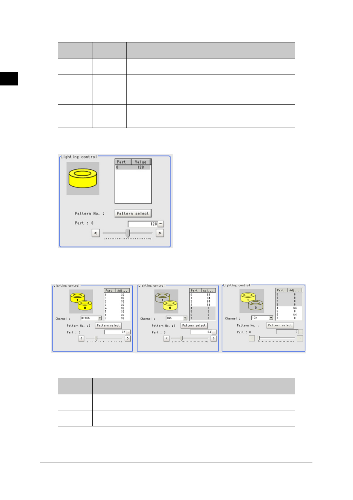
Electronic Flash Setting
This function is set when an electronic flash is used.This sets the output conditions for the signal for
synchronizing the measurement and the electronic flash timing.
In the Item Tab area, tap [Camera setting].
1.
In the "Electronic flash setting" area, specify each item.
2.
Item
S T E P
-S T G O UT
delay
STGOUT
width
Set value
[Factory default]
[0] to 511
(1 count 30μs)
1 to 63
[3]
(1 count 30μs)
Description
Set the waiting time from the time the STEP signal is input
until the electronic flash trigger output signal comes ON.
Delay Time=Count x 30μs + 90μs
Set the output time for the electronic flash trigger signal.
Select the pulse polarity of the electronic flash trigger.
Positive polarity: Flashes synchronized with the timing of the
STGOUT
polarity
●
[Positive]
●
Negative
electronic flash trigger output signal changing from OFF to
ON.
Negative: Flashes when the strobe trigger output signal
changes from ON to OFF.
Screen Adjustment Settings (Camera Image Input)
Set the lighting and lens conditions for each camera.
●
Reference: Lighting Control (p.19)
●
Reference: Line Bright (p.21)
●
Reference: Lens Adjustment Setting (p.21)
●
Reference: Common Setting for All Cameras (p.22)
18 Camera Image Input
FZ3 Processing Items List Manual
Page 21

Lighting Control
When a camera with a lighting function is connected, the light volume of the lighting can be adjusted
from the controller. Brightness can be adjusted automatically or one of the preset patterns can be
selected.
A lighting lamp image is displayed as a guide illustration.
Note
●
When one scene contains 2 or more camera image input units, lighting control can be performed only for the
first camera image input unit.
In the item tab area, tap [Screen adjust].
1.
1
Input image
In the "Lighting control" area, specify the brightness.
2.
The image display contents depend on the connected camera.
When an intelligent camera is connected
Important
●
When model FZ-SLC15 is connected, only parts 0 to 3 are active. Changing parts 4 to 7 will not affect
the light volume of lighting.
FZ3 Processing Items List Manual
Camera Image Input 19
Page 22
1
Input image
Item
Pattern
select
Turn -
Brightness
at each part
Setting
value
Pattern 0 to
16
0 to 255 x 8
ch
[0]
Description
Can be selected from a preset lighting pattern.
After the camera is installed, if the orientation of the camera does not
match the orientation of the lighting parts, tap [Turn] under the lighting
diagram. The lighting diagram rotates 90 degrees clockwise each time
you tap [Turn].
The light volume at each part can be adjusted to one of 256 levels. 0
indicates the lighting is OFF. The larger the number, the higher the
brightness.
MG-WAVE or electronic flash controller (FZ-LTA100) is connected:
Electronic flash controller FZ-LTA200 is connected:
CH0 to CH7 are used: CH0 to CH3 are used: CH4 to CH7 are used:
Item
Pattern
select
Brightness at
each part
Setting
value
Pattern 0 to
2
0 to 255
[0]
Description
Can be selected from a preset lighting pattern.
The light volume can be adjusted to one of 256 levels. 0 indicates the
lighting is OFF. The larger the number, the higher the brightness.
Other cameras are used:
20 Camera Image Input
FZ3 Processing Items List Manual
Page 23
The light volume cannot be adjusted.
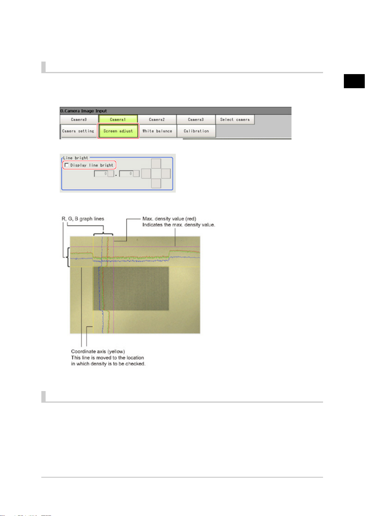
Line Bright
The graph showing the gray distribution for 1 line in the image is called the "Line bright". You can display
the line brights for R, G and B for any horizontal or vertical line.
In the item tab area, tap [Screen adjust].
1.
Place a check at "Display line bright".
2.
Move the line to the position whose density distribution you want to see.
3.
1
Input image
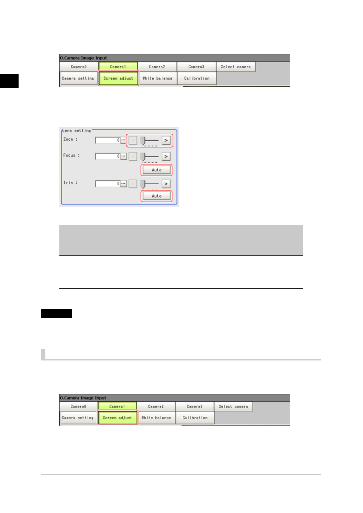
Lens Adjustment Setting
This function is only displayed when an intelligent camera or an auto-focus camera is connected.
Make lens adjustments such as the focus and zoom. The optimum value can be set automatically for the
focus and iris.
FZ3 Processing Items List Manual
Camera Image Input 21
Page 24
1
Input image
In the item tab area, tap [Screen adjust].
1.
Specify the "Zoom" size while checking the image.
2.
Tap [Auto] at "Focus" and "Iris".
3.
The focus and iris optimized for the zoomed image are set automatically.
Setting
Item
Zoom [0] to 1023
Focus [0] to 1023
Iris [0] to 31
Important
●
Auto focus and auto iris can only be used when setting with this screen open. They cannot be used during
running.
value
[Factory
default]
Description
Displays the image zoomed in and out. Depending on the focus
setting value, it may not be possible to set a large zoom value.
Adjust the focus. When [Auto] is clicked, the optimum focus for the
current image is set automatically.
Adjust the light volume that passes through the lens. When [Auto] is
clicked, the optimum iris for the current image is set automatically.
Common Setting for All Cameras
This function is only displayed when an intelligent camera or an auto-focus camera is connected. This
sets the conditions for automatically setting the focus, iris, and white balance.
In the item tab area, tap [Screen adjust].
1.
In the "Common setting for all cameras" area, set up "Camera adjust area" and "Iris base
2.
22 Camera Image Input
FZ3 Processing Items List Manual
Page 25
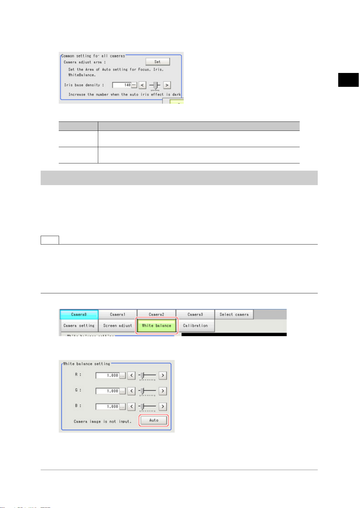
density".
Item Description
Camera adjust
area
Iris base
density
This sets the region for judging whether or not the state is appropriate when
automatically setting the focus, iris, and white balance.
Increase the number when the auto iris effect is dark.
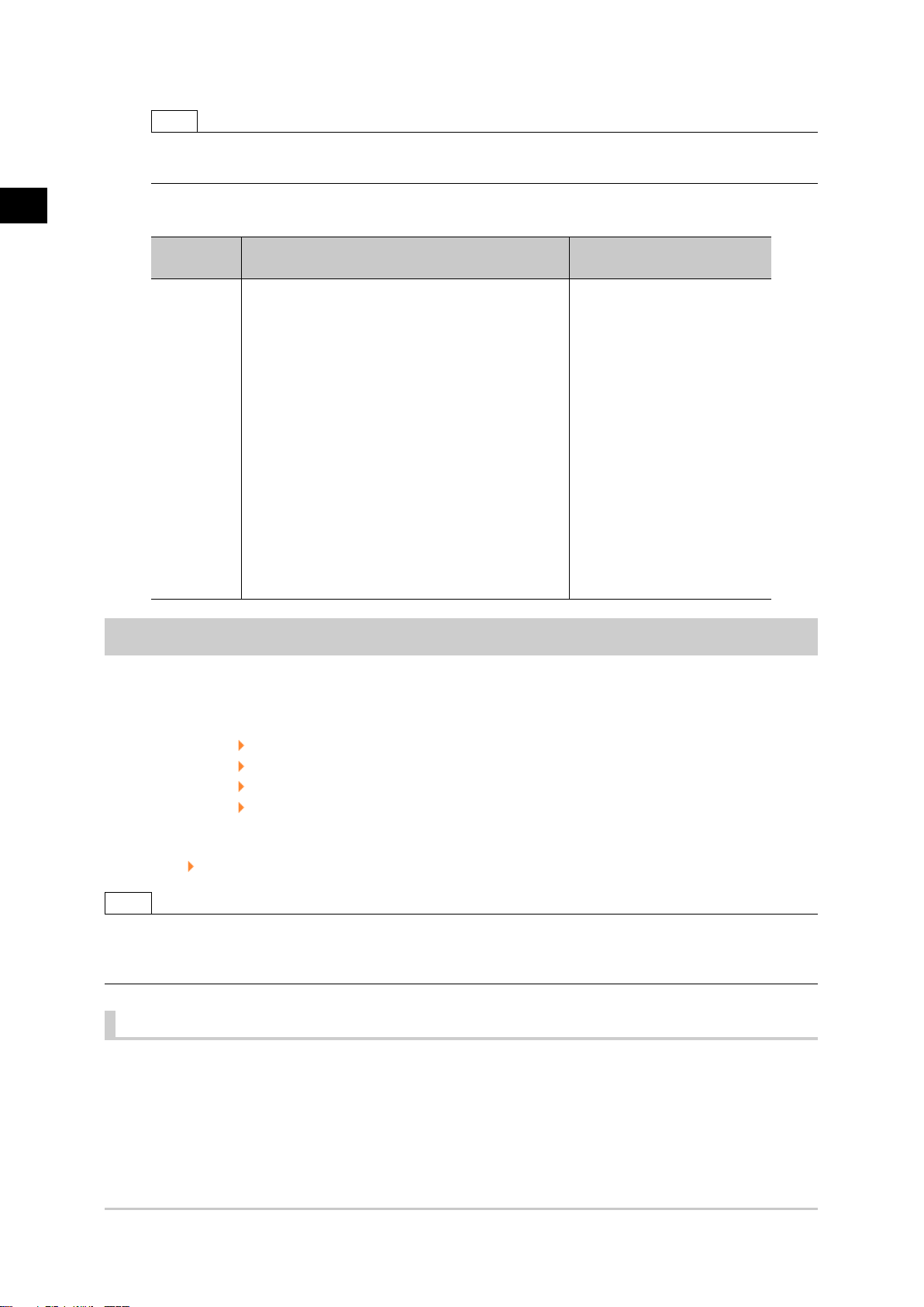
White Balance (Camera Image Input)
Set the white balance to make white objects look white by calibrating the color of images loaded from
cameras.
By adjusting the white balance, the appropriate white color can be reproduced under any lighting
conditions
Appropriate values can also be set automatically.
1
Input image
Note
●
Perform the white balance setting only when a color camera is used.
●
In the following cases, make sure to perform white balance.
●
When a new system is installed
●
When the camera or lighting is changed
Since measurement results may vary with changes of the white balance setting, be sure to verify the operation
after it has changed.
In the Item Tab area, tap [White balance].
1.
Shoot a white piece of paper or cloth.
2.
Tap [Auto].
3.
FZ3 Processing Items List Manual
Camera Image Input 23
Page 26
1
Input image
Note
●
When the "Too bright" or "Too dark" message is displayed, adjust the iris, shutter speed, gain and/or
lighting conditions until "Automatic adjustment is possible" is displayed.
Adjust the "R", "G" and "B" values as necessary.
4.
Item
White
balance
setting
●
R
●
G
●
B
0.001 to 7.999 (R, G, and B)
For FZ-SC
[R=1.183]
[G=1.000]
[B=1.323]
For FZ-SC2M
[R=1.394]
[G=1.000]
[B=1.222]
For FZ-SFC, FZ-SPC
[R=1.145]
[G=1.000]
[B=1.1889]
For FZ-SC5M
[R=1.351]
[G=1.000]
[B=2.314]
Set value
[Factory default]
Description
Adjust the white balance.
Whiteness increases when the
value of "R", "G", and "B" is
increased.
Calibration (Camera Image Input)
By setting the calibration, the measurement result can be converted and output as actual dimensions.
The calibration method is selected here.
There are three calibration methods, point, sampling, and parameter.
●
Reference: Specifying Points and Setting (Point Specification) (p.24)
●
Reference: Setting calibration through sampling measurement (sampling) (p.26)
●
Reference: Inputting and setting values (Value Setting) (p.29)
●
Reference: View Calibration Parameters (p.30)
Calibration
Reference: See "User's Manual", "Terminology Explanations" (p.309)
Note
●
In order to output measurement results in actual dimensions, set [Calibration] to "ON" in [Output parameter] for
each processing unit. If [Calibration] is "OFF" (factory default), measurement results are output as camera image
coordinate values.
Specifying Points and Setting (Point Specification)
This is a method for performing calibration by specifying arbitrary points (in pixels).
Calibration parameters are calculated automatically when actual coordinates of specified locations are
entered. Up to 3 points can be specified.
●
When magnification is the same in the X and Y directions
Specify only 2 points.
24 Camera Image Input
FZ3 Processing Items List Manual
Page 27
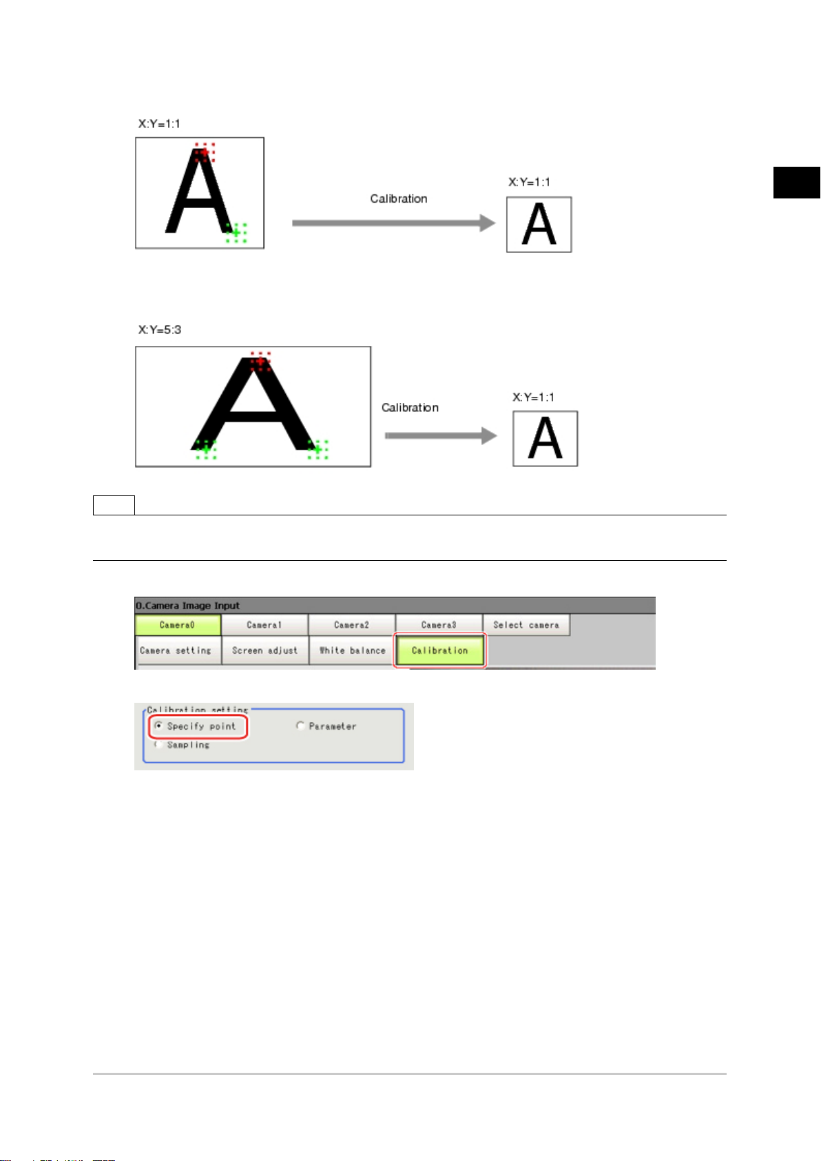
●
When magnification is not the same in the X and Y directions
Specify 3 points.
Note
●
When 2 points are specified, the coordinate system is set to the left-hand system (forward in the clockwise
direction). Specify 3 points to perform calibration including the coordinate system.
In the Item Tab area, tap [Calibration].
1.
1
Input image
In the "Calibration setting" area, select "Specify point".
2.
Tap the first point on the screen.
3.
Input the actual coordinates for the specified point.
4.
The actual coordinate input window is displayed.
FZ3 Processing Items List Manual
Camera Image Input 25
Page 28

1
Input image
Actual coordinate
Point X, Y 0 to 9999.9999 [Point you tapped in the window]
Actual X, Y -99999.9999 to 99999.9999 [0]
Set the 2nd and 3rd points in the same way.
5.
Tap [Generate calibration parameters].
6.
The calibration parameters will be generated.
Set value
[Factory default]
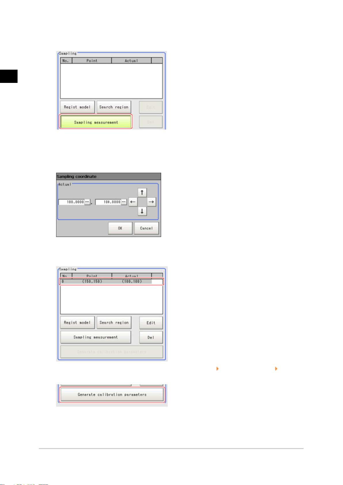
Setting Calibration through Sampling Measurement (Sampling)
This is a method for setting calibration based on measurement results.
Calibration parameters are calculated automatically when a registered model is searched and the actual
coordinates for that position entered.
In the Item Tab area, tap [Calibration].
1.
In the "Calibration setting" area, select "Sampling" .
2.
26 Camera Image Input
FZ3 Processing Items List Manual
Page 29

In the "Sampling" area, tap [Regist model].
3.
Use the Drawing tools to register the model.
4.
1
Input image
Adjust the search region as necessary.
5.
The default value setting is for the entire screen.
FZ3 Processing Items List Manual
Camera Image Input 27
Page 30
1
Input image
Tap [Sampling measurement].
6.
Measurement is performed.
The search result (cross-shaped cursor) is displayed in the Image Display area, and the
Sampling Coordinate window is displayed.
In the Sampling Coordinate window, enter the X and Y values.
7.
Tap [OK].
8.
Point coordinates and actual coordinates are registered in the "Sampling" area.
Move the object to be measured and repeat the Steps Reference: 3(p.27) to Reference: 8(p.28) .
9.
Tap [Generate calibration parameters].
10.
The calibration parameters will be generated.
28 Camera Image Input
FZ3 Processing Items List Manual
Page 31

Inputting and Setting Values (Value Setting)
Enter calibration data directly with numerical values.
In the Item Tab area, tap [Calibration].
1.
In the "Calibration setting" area, select "Parameter".
2.
In the "Parameter" area, specify values for the "Coordinate", "Origin" and "Magnification".
3.
1
Input image
Item
Coordinate
FZ3 Processing Items List Manual
Set value
[Factory default]
[Lefthand],
Righthand
Description
Left-hand type: Clockwise is forward when specifying the
coordinates.
Right-hand type: Counter-clockwise is forward when specifying
the coordinates.
Camera Image Input 29
Page 32

1
Input image
Origin
Select where the origin of the actual coordinates will be.
[Upperleft],
Lowerleft, Center
Magnificati
Tap [Generate calibration parameters].
4.
0.00001 to
on
9.99999
The calibration parameters will be generated.
View Calibration Parameters
View the set calibration data.
In the Item Tab area, tap [Calibration].
1.
In the "Calibration parameter" area, confirm the calibration data.
2.
Specify the ratio of 1 pixel to the actual dimensions.
Item Set value Description
A Calculation value
B Calculation value
C Calculation value
D Calculation value
E Calculation value
F Calculation value
30 Camera Image Input
These are calibration conversion values. Camera coordinates are
converted to actual coordinates based on these values. The
conversion formulas for actual coordinates are as follows:
●
(X, Y): Measurement point (camera coordinates), Unit: pix
●
(X', Y'): Conversion point (actual coordinates)
X'=A x X + B x Y + C
Y'=D x X + E x Y + F
FZ3 Processing Items List Manual
Page 33

Field of view Calculation value This is an actual dimension in the X direction.
Additional Explanation (Camera Image Input)
Position Compensation and Camera Image Input
When creating a scene, if a [Camera Image Input] unit is positioned after a [Position Compensation]
processing unit, that [Position Compensation] unit will be cancelled, which will cause a new image to be
read.
1
Input image
FZ3 Processing Items List Manual
Camera Image Input 31
Page 34

1
Input image
Camera Image Input HDR+
This is a processing item for just FZ3-H series high grade controllers.
You can acquire a wide dynamic lens image by combining images photographed consecutively at
different shutter speeds.
With objects that generate halation, images with low-contrast, and environments with fluctuation in the
lighting, this processing item is an effective substitute for camera image input.
Used in the Following Case
●
To acquire stable images of objects for which halation occurs easily
●
To measure images with low-contrast stably
Use high-contrast mode.
Important
●
When using an intelligent camera FZ-SLCx or an auto-focus camera FZ-SZCx, camera image input and camera
image input HDR+ cannot be used together.
Settings Flow (Camera Image Input HDR+)
To set camera image input HDR+, follow the steps below.
32 Camera Image Input HDR+
FZ3 Processing Items List Manual
Page 35

Camera Image Input HDR+ Item List
Item name Description
Camera
setting
HDR setting
Bright adjust
Screen
adjust
White
balance
Calibration
Specify the camera settings such as the electronic flash.
The setting method is the same as for [Camera Image Input].Please check it.
Reference: Camera Settings (Camera Image Input) (p.14)
Carry out the image combination and photography settings.
Reference: HDR Settings (Camera Image Input HDR+) (p.33)
Specify the brightness follow-up adjustment setting.
Reference: Bright Adjust Setting (Camera Image Input HDR+) (p.36)
Adjust the lighting and the lens.
The setting method is the same as for [Camera Image Input].Please check it.However, the iris
cannot be adjusted.
Reference: Screen Adjust Settings (Camera Image Input) (p.18)
When using a color camera, adjust the white balance.
The setting method is the same as for [Camera Image Input].Please check it.
Reference: White Balance (Camera Image Input) (p.23)
Set when measurements (camera coordinate measurement values) are to be output using actual
dimensions. Select the calibration setting method and generate the calibration parameters.
The setting method is the same as for [Camera Image Input].Please check it.
Reference: Calibration (Camera Image Input) (p.24)
1
Input image
HDR Settings (Camera Image Input HDR+)
Specify the image combination method etc.
In the Item Tab area, tap [HDR setting].
1.
In the "Mode select" area, specify the mode.
2.
When you select the mode in the "Mode select" area and specify the measurement region on the
FZ3 Processing Items List Manual
Camera Image Input HDR+ 33
Page 36

1
Input image
image, the parameters are set automatically.To finely adjust the parameters, refer to the next
items.
Set value
Item
Mode select
In the "Image input setting" area, set the items.
3.
[Factory
default]
[ HDR mode]
High
contrast
mode
Description
Generate images with stable brightness by shooting multiple images
with different shutter times based on the specified brightness range.
This is used to improve the contrast within an image.Specify the
average brightness and brightness range, fix the shutter time, shoot
multiple images, and generate images with good contrast.
HDR
Item
Minimum
brightness
Maximum
brightness
Input
number
setting
34 Camera Image Input HDR+
Set value
[Factory default]
0 to 20
[8]
0 to 20
[14]
●
[Unchecked]
●
Checked
2 to 16
[6]
Description
This item sets the minimum brightness for combining images.
This item sets the maximum brightness for combining images.
Place a check to set the number of shots manually.
Setting a high shot count provides images with low
noise.However, more processing time is required.
Setting a low shot count shortens the processing time.However,
the image is more easily affected by noise.
FZ3 Processing Items List Manual
Page 37

High contrast mode
1
Input image
Item
Average
Width
Input
number set
In the "Output setting" area, set the combination method.
4.
Item
Type of
image
combination
Set value
[Factory default]
1.00 to 20.00
[11.00]
0.01 to 1.00
[1.00]
●
[Unchecked]
●
Checked
2 to 16
[6]
Set value
[Factory
default]
[Normal] Select the combination method.
Color
Linear
Specify the average brightness for images shot.
Specify the brightness range for images shot.
Place a check to set the number of shots manually.
Setting a high shot count provides images with low
noise.However, more processing time is required.
Setting a low shot count shortens the processing time.However,
the image is more easily affected by noise.
Normal: Standard combination method. This compensates the
brightness so that dark sections on the combination image do not
become all black.
Color: This is suitable for inspecting labeling and the Gravity and
Area.This compensates the saturation when there is little hue
information in the combined image.
Linear: This is suitable for fine matching and defect inspection.In
order to output the actual brightness of the workpiece, no
compensation is performed.
The processing speed is Color (slow) - Normal - Linear (fast).
Description
Description
The current shot count and image combination time for the settings are displayed.
FZ3 Processing Items List Manual
Camera Image Input HDR+ 35
Page 38

1
Input image
Bright Adjust Setting (Camera Image Input HDR+)
This sets how far to track the brightness of the loaded images.
In the Item Tab area, tap [Brightness adjustment].
1.
Set each item in the "Bright adjust setting" area.
2.
Set value
Item
Brightness
adjustment
Minimum
Adjustment
range
Maximum
Adjustment
range
Adjust bright
ave.
[Factory
default]
[Unchecked]
Checked
0.00 to 20.00
[6.00]
0.00 to 20.00
[16.00]
0.00 to 20.00
[11.00]
Description
If a check is placed at "Brightness adjustment", the image is output
with its brightness automatically compensated.This makes it possible
to obtain images with stable brightness even if the lighting conditions
fluctuate, for example due to interfering light.
Specify the follow-up brightness minimum value.
Specify the follow-up brightness maximum value.
Specify the target for brightness follow-up.Tapping the [Set current
bright] button updates this value.
When a check is placed at "Brightness adjustment", the Brightness Adjustment range is
displayed with blue lines in the "Histogram" area.
Change the "Adjust bright ave." and brightness adjust area.
36 Camera Image Input HDR+
FZ3 Processing Items List Manual
Page 39

1
Input image
FZ3 Processing Items List Manual
Camera Image Input HDR+ 37
Page 40

1
Input image
Camera Switching
Used in the Following Case
●
When switching to images on cameras other than that has been set to [Camera Image Input]
during scene processing
Important
●
When switching from a monochrome camera to color camera, reconfigure the settings in the following units.
●
Camera switching cannot be used with camera image input HDR+.
Camera Selection (Camera Switching)
Select the cameras used for measurement.
1.
Tap [OK].
2.
The settings are finalized.
Additional Explanation (Camera Switching)
When creating a scene, [Position Compensation] will be disabled if [Camera Switching] is positioned
after a [Position Compensation] unit, and this will restore the image of the measurement object to its
former state before the position compensation was applied.
38 Camera Switching
FZ3 Processing Items List Manual
Page 41

1
Input image
FZ3 Processing Items List Manual
Camera Switching 39
Page 42

1
Input image
Measurement Image Switching
This sets the output image for the specified image conversion related processing items as the input
image for the processing items set in the flow from this processing item onward.
This is primarily used to return converted images back to their originals and to increase the images that
can be selected as conversion targets for image conversion related processing items by placing before
the image conversion related processing items.
Used in the Following Case
●
To return a converted image to its original
Parameter Settings (Measurement Image Switching)
Specify the processing unit outputting the images to display.
Select the target unit in the "Target" area.
1.
Note
●
If <Nothing> is left selected, the measurement image switching measurement result is NG.
Be sure to set something other than <Nothing>.
●
Only an image conversion related unit prior to this unit can be selected.
Tap [OK].
2.
The settings are finalized.
40 Measurement Image Switching
FZ3 Processing Items List Manual
Page 43

Measurement
This chapter describes how to set up the processing items
that execute measurement.In addition, key points for
adjustment addressing unstable measurement results and
shortening measurement time will also be introduced.
Reference: Search (p.42)
Reference: Flexible Search (p.53)
Reference: Sensitive Search (p.62)
Reference: ECM Search (p.73)
Reference: EC Circle Search (p.84)
Reference: Shape Search+ (p.94)
Reference: Classification (p.104)
Reference: Edge Position (p.114)
2
Measurement
Reference: Edge Pitch (p.124)
Reference: Scan Edge Position (p.132)
Reference: Scan Edge Width (p.145)
Reference: Color Data (p.154)
Reference: Gravity and Area (p.160)
Reference: Labeling (p.172)
Reference: Label Data (p.186)
Reference: Labeling+ (p.190)
Reference: Defect (p.209)
Reference: Precise Defect (p.217)
Reference: Fine Matching (p.225)
Reference: Character Inspection (p.236)
Reference: Date Verification (p.244)
Reference: Model Dictionary (p.253)
Reference: Barcode+ (p.261)
Reference: 2D Code+ (p.268)
FZ3 Processing Items List Manual
Reference: Circle Angle (p.275)
41
Page 44

Search
Register the feature sections of the measurement object as an image pattern (model), then find the most
similar part to these models from the input images to detect the position.
The correlation value showing the degree of similarity, measurement object position, and inclination can
be output.
2
Measurement
Used in the Following Case
●
When identifying the shape of measurement objects (for detecting defects or foreign matter)
Note
●
Search processing basic concepts
Reference: "User's Manual", "Search Processing Mechanism" (p.300)
Settings Flow (Search)
Set up searches according to the following flow.
42 Search
FZ3 Processing Items List Manual
Page 45

List of Search Items
Item name Description
This item registers the pattern characteristic of the measurement image as a model.
Model
register
Region
setting
Detection
point
Ref. position
Measurement
Output
parameter
Model parameter values can be changed as needed to address unstable measurement results or to
increase the processing speed.Normally, the factory default value will be used.
Reference: Model Registration (Search) (p.43)
This item is used to set up the measurement area.
Instead of measuring the entire input image, narrowing the measurement area shortens the
processing time.
Reference: Region Setting (Search) (p.46)
This item can be changed if necessary.Specify a position in the model that should be used as the
detection coordinates during measurement. Usually, the central position of the set model is
registered as the detection coordinates.
Reference: Detection Point (Search) (p.47)
This item can be changed if necessary.Specify the reference position within the camera's field of
view.
Reference: Reference Position (Search) (p.47)
This item specifies the judgement condition for measurement results.Specify the criteria to judge the
measurement result if the X and Y coordinates and the correlation with the model are OK.
Reference: Measurement Parameters (Search) (p.48)
This item can be changed if necessary.Normally, the factory default value will be used.
Use the output parameter to specify how to handle the coordinates.
Reference: Output Parameters (Search) (p.50)
2
Measurement
Model Registration (Search)
Register the parts to measure as the model.
The position at the time of registration is also registered in the model information.Place the
measurement object in the correct position when registering a model.
In the Item Tab area, tap [Model register].
1.
When setting a new model, you do not have to tap [Model register].
FZ3 Processing Items List Manual
Search 43
Page 46

Use the drawing tools to specify the model registration range.
2.
2
Measurement
Note
To save the entire image used for model registration, place a check at the "Save registered
3.
model" option.
Note
●
If you save the registered model image, you can re-register the model with the same image after model
parameters are adjusted.Note that the scene data size increases when a registered model image is
saved.
Tap [OK].
4.
The model is registered.
●
When a model is registered, the central coordinates of the model are registered as the detection point.A
detection point is a point output as a measurement value. If multiple figures are combined, the central
coordinates of the circumscribed rectangle are registered.
Changing Model Parameters
Model parameter values can be changed as needed to address unstable measurement results or to
increase the processing speed.Normally, the factory default value will be used.
After changing a setting, re-register the model.
In the "Model parameter" area, select the search mode, then specify a value for each item for
1.
44 Search
FZ3 Processing Items List Manual
Page 47

that mode.
Setting item
Search
mode
Set value
[factory
default]
[CR]
PT
2
Measurement
Description
Search for normalizing the brightness.This method can provide stable
measurement when there is fluctuation in the overall brightness and
when the image has low contrast.
Measures the degree of matching with the model profile.This method
can measure at higher speed when the rotation angle has a wide
range.
It is available only when a 0.3 megapixel color camera is connected.
When CR is selected
Setting item
Rotation
Angle range [-180 to 180]
Skipping angle
Smart mode
Stability
Prec.
Set value
[factory
default]
Checked
[Unchecked]
1 to 30
[5]
[Checked]
Unchecked
1 to 15
[The default
value
depend on
the
connected
camera.9 or
12]
1 to 3
[2]
Description
When the measurement object is
rotating, place a check at "Rotation" and
specify how many degrees the model
created rotates each time and through
what range of angles.A smaller skipping
angle increases stability, but slows down
the processing. The normal direction is
clockwise.
Checking the "Smart mode" option
enables a high-speed rotation
search.However, the stability may be
lowered when the model shape aspect
ratio is large or when the NOT mask is
used.
Specify which is to have priority,
measurement stability or speed.
If lowering stability does not speed up
processing, it is likely that many
candidates have been detected.In this
case, specify a larger value for
"Candidate LV" or "Stab."
Specify which is to have priority,
measurement positional precision or
speed.
FZ3 Processing Items List Manual
Search 45
Page 48

2
Measurement
If you save the model registration image, it is easy to re-register the model after model parameters are
changed.
Disp model/Input
image
Re-register
Delete Deletes models.
When PT is selected
Set value
Setting item
Angle range [-180 to 180]
Stability
[factory
default]
1 to 5
[3]
This item specifies the rotation angle range for searching.The normal
direction is clockwise.
If lowering stability does not speed up processing, it is likely that many
candidates have been detected.In this case, specify a larger value for
"Candidate LV" or "Stab."
Displaying/Re-Registering/Deleting a Model
Item Description
The model image display and input image display are switched.
When model parameters are modified, display the original model image and re-register the
model.
Description
Region Setting (Search)
Use a rectangle to specify the area where the model is searched.
Instead of measuring the entire input image, narrowing the measurement area shortens the processing
time.
In the Item Tab area, tap [Region setting].
1.
Tap [Edit].
2.
The figure setting area is displayed.
Specify the area in which to search for the model.
3.
The rectangle covering the entire screen is set. Adjust the size and position of the rectangle.
Tap [OK].
4.
The area to measure is registered.
46 Search
FZ3 Processing Items List Manual
Page 49

Detection Point (Search)
Specify a position in the model that should be used as the detection coordinates during
measurement.Usually, the central position of the set model is registered as the detection point. This
function is used to change to any desired position.
Note
●
After changing the detection coordinates to another position, re-registering the model will change it back to the
central coordinates of the model.
In the Item Tab area, tap [Detection point].
1.
In the Image Display area, the current detection point is displayed with a crosshair cursor.
Tap the position to be set as the detection point.
2.
Note
●
Displaying the image enlarged makes this tapping easier.
Reference: "Using the Zoom Function" in the "User's Manual" (p.317)
2
Measurement
If necessary, finely adjust with numeric input and the arrow buttons.
3.
Reference Position (Search)
When the model is set, this position is automatically set at the same time as the reference position.This
item can be used to change the reference position to any desired position. This is handy for measuring
the positional deviation from a certain position.
In the Item Tab area, tap [Ref. position].
1.
In the Image Display area, the current reference position will be displayed as the crosshair
cursor.
FZ3 Processing Items List Manual
Search 47
Page 50

2
Measurement
Tap the position to be set as the reference position.
2.
Note
●
Displaying the image enlarged makes this tapping easier.
Reference: "Using the Zoom Function" in the "User's Manual" (p.317)
If necessary, finely adjust with numeric input and the arrow buttons.
3.
To remeasure on the displayed image and set the reference position, tap [Measure ref.].
Measurement Parameters (Search)
Specify the search measurement conditions and the judgement conditions for the measurement results.
In the Item Tab area, tap [Measurement].
1.
In the "Measurement condition" area, specify a value for each item.
2.
Setting item
Sub-pixel
48 Search
Set value
[factory default]
●
Checked
●
[Unchecked]
Description
When a check is placed at sub-pixel, the position information can
be measured in units of sub-pixels.However, this requires more
processing time.
FZ3 Processing Items List Manual
Page 51

CandidateLV0 to 100
[70]
When executing a multi search
Specify the threshold value with which to detect candidate points
in a rough search.Specify a smaller value when model search
results are unreliable.
Setting item
Multiple
output
Detail LV
0 to 100
[75]
Sort
condition
Search No.
When the setting has been changed, tap [Measurement] in the Detail area to verify whether
3.
0 to 31
[0]
Set value
[factory default]
●
Checked
●
[Unchecked]
●
Corr. ascending
●
[Corr. descending]
●
X ascending
●
X descending
●
Y ascending
●
Y descending
Description
Select to execute a multi search.
Specify the threshold value with which to detect candidate
points in a detail search.
Specify the conditions by which the search number is
re-assigned.
When sorting referencing the X and Y coordinates, the
upper left is the origin.
Input the search number for outputting the data.
measurements can be made correctly.
Set up the judgement condition.
4.
2
Measurement
Note
●
The values beside each item are measurement results of the displayed image.Take these values into
consideration to determine the upper and lower limits.
Setting item Set value Description
Count 0 to 32 Specify the number of detections that are judged to be OK.
-99999.9999
Measure X
Measure Y
FZ3 Processing Items List Manual
to
99999.9999
-99999.9999
to
99999.9999
Specify the range of X-axis shifting that is judged to be OK.
Specify the range of Y-axis shifting that is judged to be OK.
Search 49
Page 52

Measure
angle
-180 to 180 Specify the range of angles that are judged to be OK.
Correlation 0 to 100
Specify the range of correlation values that are judged to be
OK.However, when the correlation value of the measurement result is
0, the judgement result will be NG regardless of the lower limit setting.
2
Measurement
Specify how to treat the coordinates to be output to the external device as measurement results.This
item can be changed if necessary.Normally, the factory default value will be used.
Important
Output Parameters (Search)
●
After setting up the measurement parameters, changing the output parameters will cause measurement results
to vary accordingly.If the output parameters have been changed, re-specify the measurement, too.
Tap [Output parameter] in the Item Tab area.
1.
Specify each of the following items.
2.
Set value
Setting item
[factory
Description
default]
●
Output
Coordinates
scroll]
●
scroll
[After
Before
As measurement results, select whether to output coordinate values
to external devices before or after the position deflection correction is
applied.
Select whether to reflect the calibration in the values output to the
Calibration
●
[OFF]
ON
external device as measurement results.
ON: Output the coordinates converted into actual dimensions.
●
OFF: Output the camera coordinate values.
Reflect to
overall
judgement
●
●
[ON]
OFF
Enables choosing whether or not the judgement results of this
processing unit is reflected in the scene overall judgement.
Key Points for Test Measurement and Adjustment (Search)
The following content is displayed in the "Detail result" area as text.
Important
●
Executing test measurements will also update the measurement results and the figures in the image.
50 Search
FZ3 Processing Items List Manual
Page 53

Displayed items Description
Judge Judgement result
Count Count
Correlation Correlation value
Position X X coordinate of the position where the model is detected
Position Y Y coordinate of the position where the model is detected
Angle Angle of the position where the model is detected
Key Points for Adjustment
Select the adjustment method referring to the following points.
When the measurement results are unstable
Searching other positions
2
Measurement
Parameter to
be adjusted
Model
parameter
Measurement
Specify a larger value for the "Prec."
If the measurement results are unstable only when "Rotation" is selected, specify a smaller value for
the "Skipping angle".
When "Rotation" is selected, if the model shape is complex, uncheck the "Smart mode" option.
If the image has low contrast or blurred edges, set the "Search mode" to "CR".
If the model image consists of detailed figures, specify a larger value for "Stab."
If the precision is low, place a check at "Sub-pixel".
If images that should be judged OK vary greatly, specify a smaller value for "Candidate LV".
If the model image is small and unstable, specify a smaller value for the "Reduction".
Remedy
The judgement is NG (insufficient memory)
Parameter to be
adjusted
Region setting Make the search region as small as possible.
Bring "Stab." close to the factory default value.
Model parameter
Bring the "Skipping angle" close to the factory default value.
Specify a smaller value for "Prec.".
Remedy
When the processing speed is slow
Parameter to
be adjusted
Region
setting
Model Make the area to register as the model as small as possible.
FZ3 Processing Items List Manual
Make the search region as small as possible.
Remedy
Search 51
Page 54

Model
parameter
2
Measurement
Measurement
The following values can be output using processing items related to results output. It is also possible to
reference measurement values from expressions and other processing units.
If the model image is a simple figure or a large figure, specify a smaller value for "Stab."If lowering
stability does not speed up processing, it is likely that many candidates have been detected. Raise
the "Candidate LV" in [Measurement].
When "Rotation" is selected and the model image is a simple figure, specify a larger value for
"Skipping angle".
When "Rotation" is selected and the model image is a simple figure, place a check at "Smart mode".
If the position precision is high, specify a smaller value for "Prec.".
If the rotation angle range is large, set the "Search mode" to "PT".
If images that should be judged OK vary little, specify a larger value for "Candidate LV".
If the position precision is high, uncheck "Sub-pixel".
Measurement Results for Which Output Is Possible (Search)
Measurement items
Judgement JG Judgement result
Count C
Correlation value CR Correlation value with the model
Measurement coordinate X X X coordinate of the position where the model is detected
Measurement coordinate Y Y Y coordinate of the position where the model is detected
Measurement angle TH Angle of the position where the model is detected
Reference position X SX X coordinate of the reference position of the registered model
Reference position Y SY Y coordinate of the reference position of the registered model
Reference angle ST Angle of the registered model
Detection point RX RX X coordinate of the registered model
Detection point RY RY Y coordinate of the registered model
Correlation value N (N = 00
to 31)
Position N (N = 00 to 31) XN Detected search N position X (N = 00 to 31)
Position N (N = 00 to 31) YN Detected search N position Y (N = 00 to 31)
Angle N (N = 00 to 31) THN Detected search N angle TH (N = 00 to 31)
Character
string
Number of search items detected
If none detected, 0
CRN Detected search N correlation value (N = 00 to 31)
Description
52 Search
FZ3 Processing Items List Manual
Page 55

Flexible Search
In Flexible Search, multiple measurement object features (models) are registered beforehand.Parts from
input images that most resemble the multiple models are searched for, and correlation (similarity) and
position are determined.
Used in the Following Case
●
To treat models with only slight variations as the same and prevent excessive filtering out.
2
Measurement
Note
●
Search processing basic concepts
Reference: "User's Manual", "Search Processing Mechanism" (p.300)
Settings Flow (Flexible Search)
Set up flexible search according to the following steps.
FZ3 Processing Items List Manual
Flexible Search 53
Page 56

2
Measurement
Model
register
Region
setting
Measurement
Output
parameter
List of Flexible Search Items
Item name Description
This item registers the pattern characteristic of the measurement image as a model.
Model parameter values can be changed as needed to address unstable measurement results or to
increase the processing speed.Normally, the factory default value will be used.
Reference: Model Registration (Flexible Search) (p.54)
This item is used to set up the measurement area.
Instead of measuring the entire input image, narrowing the measurement area shortens the
processing time.
Reference: Region Setting (Flexible Search) (p.57)
This item specifies the judgement condition for measurement results.Specify the criteria to judge the
measurement result if the X and Y coordinates and the correlation with the model are OK.
Reference: Measurement Parameters (Flexible Search) (p.57)
This item can be changed if necessary.Normally, the factory default value will be used.
Use the output parameter to specify how to handle the coordinates.
Reference: Output Parameters (Flexible Search) (p.59)
Model Registration (Flexible Search)
Register the parts to measure as the model.
A total of 5 models, 0 through 4, can be registered, with no restriction on the size.
If a model has different printing qualities and shapes, more than one models should be registered.
The position at the time of registration is also registered in the model information.Place the
measurement object in the correct position when registering a model.
In the Item Tab area, tap [Model register].
1.
In the "Setting model" area, select a model and tap [New].
2.
54 Flexible Search
FZ3 Processing Items List Manual
Page 57

Use the drawing tools to specify the model registration range.
3.
In the figure setting area, tap [OK].
4.
The model is registered and its center X and Y coordinate values are displayed in the "Setting
model" area.
The image specified for the model is displayed in the Image Display area.
2
Measurement
To register two or more models, repeat the Steps Reference: 2(p.54) to Reference: 4(p.55) .
5.
Important
●
When a model is registered, the center of the model is registered as the detection point.A detection point is a
point output as a measurement value.If multiple figures are combined, the central coordinates of the
circumscribed rectangle are registered.
FZ3 Processing Items List Manual
Flexible Search 55
Page 58

Model parameter values can be changed as needed to address unstable measurement results or to
increase the processing speed.Normally, the factory default value will be used.
After changing a setting, re-register the model.
2
Measurement
Changing Model Parameters
In the "Model parameter" area, select the search mode, then specify a value for each item for
1.
that mode.
Set value
Setting item
Search
mode
[CR]
PT
[factory
default]
Description
Search for normalizing the brightness.This method can provide stable
measurement when there is fluctuation in the overall brightness and
when the image has low contrast.
Measures the degree of matching with the model profile.This method
can measure at higher speed when the rotation angle has a wide
range.
It is available only when a 0.3 megapixel color camera is connected.
When CR is selected
Setting item
Rotation
Angle range [-180 to 180]
Smart mode
Skipping angle
Set value
[factory
default]
Checked
[Unchecked]
1 to 30
[5]
[Checked]
Unchecked
Description
When the measurement object is
rotating, place a check at "Rotation" and
specify how many degrees the model
created rotates each time and through
what range of angles.A smaller skipping
angle increases stability, but slows down
the processing.The normal direction is
clockwise.
Checking the "Smart mode" option
enables a high-speed rotation
search.However, the stability may be
lowered when the model shape aspect
ratio is large or when the NOT mask is
used.
56 Flexible Search
FZ3 Processing Items List Manual
Page 59

Stability
Preciseness
When PT is selected
Set value
Setting item
Angle range [-180 to 180]
Stability
[factory
default]
1 to 5
[3]
1 to 15
[The default
value
depend on
the
connected
camera.9 or
12]
1 to 3
[2]
This item specifies the rotation angle range for searching.The normal
direction is clockwise.
If lowering stability does not speed up processing, it is likely that many
candidates have been detected.In this case, specify a larger value for
"Candidate level" or "Stab."
Specify which is to have priority,
measurement stability or speed.
If lowering stability does not speed up
processing, it is likely that many
candidates have been detected.In this
case, specify a larger value for
"Candidate LV" or "Stab."
Specify which is to have priority,
measurement positional precision or
speed.
Description
2
Measurement
Region Setting (Flexible Search)
Use a rectangle to specify the area where the model is searched.
Instead of measuring the entire input image, narrowing the measurement area shortens the processing
time.
In the Item Tab area, tap [Region setting].
1.
Tap [Edit].
2.
The figure setting area is displayed.
Specify the area in which to search for the model.
3.
The rectangle covering the entire screen is set. Adjust the size and position of the rectangle.
Tap [OK].
4.
The area to measure is registered.
Measurement Parameters (Flexible Search)
Specify the search measurement conditions and the judgement conditions for the measurement results.
In the Item Tab area, tap [Measurement].
1.
FZ3 Processing Items List Manual
Flexible Search 57
Page 60

In the "Measurement condition" area, specify a value for each item.
2.
2
Measurement
Setting item
Sub-pixel
Candidate
level
When the setting has been changed, tap [Measurement] in the Detail area to verify whether
3.
Set value
[factory default]
●
Checked
●
[Unchecked]
0 to 100
[70]
Description
When a check is placed at sub-pixel, the position information can
be measured in units of sub-pixels.However, this requires more
processing time.
Specify the threshold value with which to detect candidate points
in a rough search.Specify a smaller value when model search
results are unreliable.
measurements can be made correctly.
Set up the judgement condition.
4.
Note
●
The values beside each item are measurement results of the displayed image.Take these values into
consideration to determine the upper and lower limits.
Setting item Set value Description
Position X
Position Y
Search
angle
Correlation 0 to 100
58 Flexible Search
-99999.9999
to
99999.9999
-99999.9999
to
99999.9999
-180 to 180 Specify the range of angles that are judged to be OK.
Specify the range of X-axis shifting that is judged to be OK.
Specify the range of Y-axis shifting that is judged to be OK.
Specify the range of correlation values that are judged to be
OK.However, when the correlation value of the measurement result is
0, the judgement result will be NG regardless of the lower limit setting.
FZ3 Processing Items List Manual
Page 61

Output Parameters (Flexible Search)
Specify how to treat the coordinates to be output to the external device as measurement results.This
item can be changed if necessary.Normally, the factory default value will be used.
Important
●
After setting up the measurement parameters, changing the output parameters will cause measurement results
to vary accordingly.If the output parameters have been changed, re-specify the measurement, too.
Tap [Output parameter] in the Item Tab area.
1.
Specify each of the following items.
2.
2
Measurement
Set value
Setting item
[factory
Description
default]
●
Output
Coordinates
scroll]
●
scroll
[After
Before
As measurement results, select whether to output coordinate values
to external devices before or after the position deflection correction is
applied.
Select whether to reflect the calibration in the values output to the
Calibration
●
[OFF]
ON
external device as measurement results.
ON: Output the coordinates converted into actual dimensions.
●
OFF: Output the camera coordinate values.
Reflect to
overall
judgement
●
●
[ON]
OFF
Enables choosing whether or not the judgement results of this
processing unit is reflected in the scene overall judgement.
Key Points for Test Measurement and Adjustment (Flexible Search)
The following content is displayed in the "Detail result" area as text.
Displayed items Description
Judge Judgement result
Model number Model No. of the biggest correlation
Correlation Correlation value
Position X X coordinate of the position where the model is detected
Position Y Y coordinate of the position where the model is detected
Angle Angle of the position where the model is detected
FZ3 Processing Items List Manual
Flexible Search 59
Page 62

Note
●
If the model is an ellipse, its circumscribing rectangle is displayed as the search result of the model.
Key Points for Adjustment
2
Select the adjustment method referring to the following points.
Measurement
When the measurement results are unstable
Searching other positions
Parameter to
be adjusted
Model
parameter
Measurement
The judgement is NG (insufficient memory)
Region setting Make the search region as small as possible.
Model parameter
Specify a larger value for the "Prec."
If the measurement results are unstable only when "Rotation" is selected, specify a smaller value for
the "Skipping angle".
When "Rotation" is selected, if the model shape is complex, uncheck the "Smart mode" option.
If the image has low contrast or blurred edges, set the "Search mode" to "CR".
If the model image consists of detailed figures, specify a larger value for "Stab."
If the precision is low, place a check at "Sub-pixel".
If images that should be judged OK vary greatly, specify a smaller value for "Candidate level".
If the model image is small and unstable, specify a smaller value for the "Reduction".
Parameter to be
adjusted
Remedy
Remedy
Bring "Stab." close to the factory default value.
Bring the "Skipping angle" close to the factory default value.
Specify a smaller value for "Prec.".
When the processing speed is slow
Parameter to
be adjusted
Region
setting
Model Make the area to register as the model as small as possible.
Model
parameter
Measurement
60 Flexible Search
Make the search region as small as possible.
If the model image is a simple figure or a large figure, specify a smaller value for "Stab."If lowering
stability does not speed up processing, it is likely that many candidates have been detected. Raise
the "Candidate level" in [Measurement].
When "Rotation" is selected and the model image is a simple figure, specify a larger value for
"Skipping angle".
When "Rotation" is selected and the model image is a simple figure, place a check at "Smart mode".
If the position precision is high, specify a smaller value for "Prec.".
If the rotation angle range is large, set the "Search mode" to "PT".
If images that should be judged OK vary little, specify a larger value for "Candidate level".
If the position precision is high, uncheck "Sub-pixel".
Remedy
FZ3 Processing Items List Manual
Page 63

Measurement Results for Which Output Is Possible (Flexible Search)
The following values can be output using processing items related to results output.It is also possible to
reference measurement values from expressions and other processing units.
Measurement items
Judgement JG Judgement result
Model No. NO Model No. of the biggest correlation
Correlation value CR Correlation with the model
Measurement coordinate X X X coordinate of the position where the model is detected
Measurement coordinate Y Y Y coordinate of the position where the model is detected
Measurement angle TH Angle of the position where the model is detected
Reference position X SX X coordinate of the reference position of the registered model
Reference position Y SY Y coordinate of the reference position of the registered model
Reference angle ST Angle of the registered model
Detection point RX RX X coordinate of the registered model
Detection point RY RY Y coordinate of the registered model
Character
string
Description
2
Measurement
FZ3 Processing Items List Manual
Flexible Search 61
Page 64

Sensitive Search
The registered models are automatically finely divided and matched in detail.Of the divided models, the
one with the lowest correlation is output. Sensitive search is suitable when the difference between the
model image and measurement image is small and regular searches do not produce differences in
correlation.
2
Measurement
Used in the Following Case
●
When identifying the shape of the divided area
Settings Flow (Sensitive Search)
Set up sensitive search according to the following steps.
62 Sensitive Search
FZ3 Processing Items List Manual
Page 65

List of Sensitive Search Items
Item name Description
This item registers the pattern characteristic of the measurement image as a model.
Model
register
Region
setting
Detection
point
Ref. position
Measurement
Output
parameter
Model parameter values can be changed as needed to address unstable measurement results or to
increase the processing speed.Normally, the factory default value will be used.
Reference: Model Registration (Sensitive Search) (p.63)
This item is used to set up the measurement area.
Instead of measuring the entire input image, narrowing the measurement area shortens the
processing time.
Reference: Region Setting (Sensitive Search) (p.66)
This item can be changed if necessary.Specify a position in the model that should be used as the
detection coordinates during measurement.Usually, the central position of the set model is
registered as the detection coordinates.
Reference: Detection Point (Sensitive Search) (p.67)
This item can be changed if necessary.Specify the reference position within the camera's field of
view.
Reference: Reference Position (Sensitive Search) (p.67)
This item specifies the judgement condition for measurement results.Specify the criteria to judge the
measurement result if the X and Y coordinates and the correlation with the model are OK.
Reference: Measurement Parameters (Sensitive Search) (p.68)
This item can be changed if necessary.Normally, the factory default value will be used.
Use the output parameter to specify how to handle the coordinates.
Reference: Output Parameters (Sensitive Search) (p.69)
2
Measurement
Model Registration (Sensitive Search)
Register the parts to measure as the model.
The position at the time of registration is also registered in the model information.Place the
measurement object in the correct position when registering a model.
In the Item Tab area, tap [Model register].
1.
When setting a new model, you do not have to tap [Model register].
Use the drawing tools to specify the model registration range.
2.
To save the entire image used for model registration, place a check at the "Save registered
3.
model" option.Also, when registering a model but not holding the disable setting for the
sub-region set during the last time the model was registered, uncheck the "Keep disabled
setting" option.
FZ3 Processing Items List Manual
Sensitive Search 63
Page 66

2
Measurement
Model parameter values can be changed as needed to address unstable measurement results or to
increase the processing speed.Normally, the factory default value will be used.
After changing a setting, re-register the model.
Setting item
Keep disabled
setting
Save
registered
model.
Tap [OK].
4.
Set value
[factory default]
●
[Checked]
●
Unchecked
●
Checked
●
[Unchecked]
When the model is registered, this holds the disable setting for
the sub-region set during the last time the model was
registered.
To save the entire image used for model registration, place a
check at this option.
The model is registered.
Changing Model Parameters
In the "Model parameter" area, set each item.
1.
Description
Setting item
Rotation
Set value
[factory default]
●
Checked
●
[Unchecked]
Angle range [-180 to 180]
Skipping
angle
Smart mode
1 to 30
[5]
●
[Checked]
●
Unchecked
1 to 15
[The default
Stability
value depend on
the connected
camera.9 or 12]
Preciseness
1 to 3
[2]
Changing Sub-model parameter
Description
When the measurement object is rotating, place a
check at "Rotation" and specify how many degrees
the model created rotates each time and through
what range of angles.A smaller skipping angle
increases stability, but slows down the
processing.The normal direction is clockwise.
Checking the "Smart mode" option enables a
high-speed rotation search.However, the stability
may be lowered when the model shape aspect
ratio is large or when the NOT mask is used.
Specify which is to have priority, measurement
stability or speed.
If lowering stability does not speed up processing,
it is likely that many candidates have been
detected.In this case, specify a larger value for
"Candidate level" or "Stab."
Specify which is to have priority, measurement
positional precision or speed.
Set the "Sensitive model setting" as necessary.
64 Sensitive Search
FZ3 Processing Items List Manual
Page 67

Tap [Sensitive model setting] in the model parameter.
1.
Set up the sub-model parameter.
2.
2
Measurement
Setting item
Sub-model
number X
Sub-model
number Y
Stability
Preciseness
Plain
inspection
Set value
[factory default]
0 to 10
[4]
0 to 10
[4]
1 to 15
[The default value
depend on the
connected
camera.12 or 15]
1 to 3
[2]
●
Checked
●
[Unchecked]
Description
This sets the number of divisions of the registered model in the
X direction.
This sets the number of divisions of the registered model in the
Y direction.
Specify which is to have priority, measurement stability or
speed.
If lowering stability does not speed up processing, it is likely that
many candidates have been detected.In this case, specify a
larger value for "Candidate level" or "Stab."
Specify which is to have priority, measurement positional
precision or speed.
Specify whether or not to inspect the plain region.
FZ3 Processing Items List Manual
Sensitive Search 65
Page 68

2
Measurement
Disabled setting
You can specify enable/disable of each sub-region.
Tap the region you wish to disable and select "Disabled".
1.
To release the disabling of a region, tap "Enable All".
Region Setting (Sensitive Search)
Use a rectangle to specify the area where the model is searched.
Instead of measuring the entire input image, narrowing the measurement area shortens the processing
time.
In the Item Tab area, tap [Region setting].
1.
Tap [Edit].
2.
The figure setting area is displayed.
Specify the area in which to search for the model.
3.
The rectangle covering the entire screen is set. Adjust the size and position of the rectangle.
Tap [OK].
4.
The area to measure is registered.
66 Sensitive Search
FZ3 Processing Items List Manual
Page 69

Detection Point (Sensitive Search)
Specify a position in the model that should be used as the detection coordinates during
measurement.Usually, the central position of the set model is registered as the detection point.This
function is used to change to any desired position.
Note
●
After changing the detection coordinates to another position, re-registering the model will change it back to the
central coordinates of the model.
In the Item Tab area, tap [Detection point].
1.
In the Image Display area, the current detection point is displayed with a crosshair cursor.
Tap the position to be set as the detection point.
2.
Note
●
Displaying the image enlarged makes this tapping easier.
Reference: "Using the Zoom Function" in the "User's Manual" (p.317)
2
Measurement
If necessary, finely adjust with numeric input and the arrow buttons.
3.
Reference Position (Sensitive Search)
When the model is set, this position is automatically set at the same time as the reference position.This
item can be used to change the reference position to any desired position.This is handy for measuring
the positional deviation from a certain position.
In the Item Tab area, tap [Ref. position].
1.
In the Image Display area, the current reference position will be displayed as the crosshair
cursor.
FZ3 Processing Items List Manual
Sensitive Search 67
Page 70

2
Measurement
Tap the position to be set as the reference position.
2.
Note
●
Displaying the image enlarged makes this tapping easier.
Reference: "Using the Zoom Function" in the "User's Manual" (p.317)
If necessary, finely adjust with numeric input and the arrow buttons.
3.
To remeasure on the displayed image and set the reference position, tap [Measure ref.].
Measurement Parameters (Sensitive Search)
Specify the sensitive search measurement conditions and the judgement conditions for the
measurement results.
In the Item Tab area, tap [Measurement].
1.
In the "Measurement condition" area, specify a value for each item.
2.
Setting item
Sub-pixel
68 Sensitive Search
Set value
[factory default]
●
Checked
●
[Unchecked]
Description
When a check is placed at sub-pixel, the position information can
be measured in units of sub-pixels.However, this requires more
processing time.
FZ3 Processing Items List Manual
Page 71

Candidate
level
Sub-region
margin
0 to 100
[60]
0 to 10
[6]
Specify the threshold value with which to detect candidate points
in a rough search.Specify a smaller value when model search
results are unstable.
This is set when expanding the measurement region for
sub-region measurement.Specify a larger value when model
search results are unstable.
When the setting has been changed, tap [Measurement] in the Detail area to verify whether
3.
measurements can be made correctly.
Set up the judgement condition.
4.
Setting item Set value Description
-99999.9999
Measure X
Measure Y
Search
angle
Correlation 0 to 100
Deviation 0 to 221
NG
Sub-region
to
99999.9999
-99999.9999
to
99999.9999
-180 to 180 Specify the range of angles that are judged to be OK.
0 to 100 Specify the range of NG sub-region that are judged to be OK.
Specify the range of X-axis shifting that is judged to be OK.
Specify the range of Y-axis shifting that is judged to be OK.
Specify the range of correlation values that are judged to be
OK.However, when the correlation value of the measurement result is
0, the judgement result will be NG regardless of the lower limit setting.
Specify the range of density deviations that are judged to be OK.The
higher the proportion of plain sections, the higher this value.
This is enabled when plain inspection is set in the sensitive model
settings.
2
Measurement
Output Parameters (Sensitive Search)
Specify how to treat the coordinates to be output to the external device as measurement results.This
item can be changed if necessary.Normally, the factory default value will be used.
Tap [Output parameter] in the Item Tab area.
1.
FZ3 Processing Items List Manual
Sensitive Search 69
Page 72

2
Measurement
Specify each of the following items.
2.
Setting item
Output coordinates
Calibration
Reflect to overall
judgement
Display cursor setting
Position
Sub-region
Set value
[factory
default]
●
[After
scroll]
●
Before
scroll
●
[OFF]
●
ON
●
[ON]
●
OFF
●
[ON]
●
OFF
●
ON
●
[OFF]
Description
As measurement results, select whether to output
coordinate values to external devices before or after
the position deflection correction is applied.
Select whether to reflect the calibration in the values
output to the external device as measurement results.
ON: Output the coordinates converted into actual
dimensions.
OFF: Output the camera coordinate values.
Enables choosing whether or not the judgement results
of this processing unit is reflected in the scene overall
judgement.
The measurement coordinate position of the detected
model is displayed at the cursor.
The coordinate position of the region with the lowest
correlation value of the sub-regions is displayed at the
cursor.
Key Points for Test Measurement and Adjustment (Sensitive Search)
The following content is displayed in the "Detail result" area as text.
Note
●
Executing test measurements will also update the measurement results and the figures in the image.
Displayed items Description
Judge Judgement result
Correlation Lowest correlation value in the sub-region
Position X X coordinate of the position where the model is detected
Position Y Y coordinate of the position where the model is detected
70 Sensitive Search
FZ3 Processing Items List Manual
Page 73

Angle Angle of the position where the model is detected
Deviation Highest density deviation in the sub-region
NG Sub-region NG region count
Key Points for Adjustment
Select the adjustment method referring to the following points.
When the measurement results are unstable
Searching other positions
Parameter to
be adjusted
Model
parameter
Sub-model
parameter
Measurement
Specify a larger value for the "Prec."
If the measurement results are unstable only when "Rotation" is selected, specify a smaller value for
the "Skipping angle".
When "Rotation" is selected, if the model shape is complex, uncheck the "Smart mode" option.
If the model image consists of detailed figures, specify a larger value for "Stab."
If images that should be judged OK vary greatly, specify a larger value for "Sub-model number X"
and "Sub-model number Y".
If the precision is low, place a check at "Sub-pixel".
If images that should be judged OK vary greatly, specify a smaller value for "Candidate level".
If images that should be judged OK vary greatly, specify a larger value for "Sub-region margin".
Remedy
2
Measurement
The judgement is NG (insufficient memory)
Parameter to be
adjusted
Region setting Make the search region as small as possible.
Bring "Stab." close to the factory default value.
Model parameter
Sub-model
parameter
Bring the "Skipping angle" close to the factory default value.
Specify a smaller value for "Prec.".
Specify a larger value for "Sub-model number X" and "Sub-model number Y".
When the processing speed is slow
Parameter to
be adjusted
Region
setting
Model
Registration
Make the search region as small as possible.
Make the area to register as the model as small as possible.
Remedy
Remedy
FZ3 Processing Items List Manual
Sensitive Search 71
Page 74

Model
parameter
2
Measurement
Sub-model
parameter
Measurem en
parameter
The following values can be output using processing items related to results output.It is also possible to
reference measurement values from expressions and other processing units.
If the model image is a simple figure or a large figure, specify a smaller value for "Stab."If lowering
stability does not speed up processing, it is likely that many candidates have been detected. Raise
the "Candidate level" in [Measurement].
When "Rotation" is selected and the model image is a simple figure, specify a larger value for
"Skipping angle".
When "Rotation" is selected and the model image is a simple figure, place a check at "Smart mode".
If the position precision is high, specify a smaller value for "Prec.".
If images that should be judged OK vary greatly, specify a larger value for "Sub-model number X"
and "Sub-model number Y".
If images that should be judged OK vary little, specify a larger value for "Candidate level".
t
If the position precision is high, uncheck "Sub-pixel".
Measurement Results for Which Output Is Possible (Sensitive Search)
Measurement items
Judgement JG Judgement result
Correlation value CR Correlation with the model
Deviation DV Deviation
Measurement coordinate X X X coordinate of the position where the model is detected
Measurement coordinate Y Y Y coordinate of the position where the model is detected
Measurement angle TH Angle of the position where the model is detected
Reference position X SX X coordinate of the reference position of the registered model
Reference position Y SY Y coordinate of the reference position of the registered model
Reference angle ST Angle of the registered model
Detection point X RX X coordinate of the registered model
Detection point Y RY Y coordinate of the registered model
NG Sub-region CT NG region count
Sub-region Number AN Region number with the lowest correlation value
Sub-region Number(X) ANX X direction column number for the output region
Sub-region Number(Y) ANY Y direction line number for the output region
Sub-region Pos. X DX X coordinate of the detected sub-region
Sub-region Pos. Y DY Y coordinate of the detected sub-region
Correlation (sub-region N)
(N = 0 to 99)
Deviation (sub-region N)
(N = 0 to 99)
Character
string
CRN Correlation (sub-region N)
DVN Deviation (sub-region N)
Description
72 Sensitive Search
FZ3 Processing Items List Manual
Page 75

ECM Search
This processing item searches the input image for parts having a high degree of similarity to the target
mark (model), and measures its correlation value (similarity) and position.
In a normal search, image pattern models are used that look at the color and light/dark information, but
in an ECM search, models are used that look at the profile information.Therefore, this processing
assures a reliable search even for low-contrast or noisy images.
Used in the Following Case
●
To measure the location of a mark
2
Measurement
Settings Flow (ECM Search)
Set up ECM search according to the following steps.
FZ3 Processing Items List Manual
ECM Search 73
Page 76

2
Measurement
Model
register
Error model
Region
setting
Detection
point
Ref. position
Measurement
Output
parameter
List of ECM Search Items
Item name Description
This item registers the pattern characteristic of the measurement image as a model.
Model parameter values can be changed as needed to address unstable measurement results or to
increase the processing speed.Normally, the factory default value will be used.
Reference: Model Registration (ECM Search) (p.74)
This item can be changed if necessary.As an error model, register a model with similar
characteristics to the registered one, but with its correlation value lowered when measured.
Reference: Error Model Registration (ECM Search) (p.78)
This item is used to set up the measurement area.
Instead of measuring the entire input image, narrowing the measurement area shortens the
processing time.
Reference: Region Setting (ECM Search) (p.78)
This item can be changed if necessary.Usually, the central position of the registered model is
registered as the search detection point.
Reference: Detection Point (ECM Search) (p.78)
This item can be changed if necessary.Usually, the central position of the registered region is
registered as the reference position.
Reference: Reference Position (ECM Search) (p.79)
This item specifies the judgement condition for measurement results.Specify the criteria to judge the
measurement result if the X and Y coordinates and the correlation with the model are OK.
Reference: Measurement Parameters (ECM Search) (p.80)
This item can be changed if necessary.Normally, the factory default value will be used.
Use the output parameter to specify how to handle the coordinates.
Reference: Output Parameters (ECM Search) (p.81)
Model Registration (ECM Search)
Register the pattern characteristic of the measurement object as a model. In an ECM search, only the
image profile information is registered.
Important
●
For ECM search, 6 pixels at each end of an image cannot be registered as a part of the model.
●
Upon re-registering a model, error models are deleted. Register error models when re-registering a model.
In the item tab area, tap [Model register].
1.
74 ECM Search
FZ3 Processing Items List Manual
Page 77

When setting a new model, you do not have to tap [Model register].
Use the drawing tools to specify the model registration range.
2.
In the figure setting area, tap [OK].
3.
The model is registered.
Tap [Edge extraction], then confirm the edge extraction image.
4.
If there is a break in the profile of the measurement object, adjust the edge level.
Reference: Adjusting the edge level (p.77)
If there is unnecessary profile information in the model, tap [Mask register] to set the mask.
5.
Reference: Mask any unnecessary items. (p.76)
To check the model display, tap [Display model].
6.
The registered model image is displayed in the image display area.
Note
●
When a model is registered, the center of the model is registered as the detection point coordinate. A detection
point is a point output as a measurement value.
2
Measurement
Changing Model Parameters
Model parameter values can be changed as needed to address unstable measurement results or to
increase the processing speed. Normally, the factory default value will be used.
After changing a setting, check whether measurement can be done properly by performing an actual
measurement.
In the "Model parameter" area, specify a value for each item.
1.
FZ3 Processing Items List Manual
ECM Search 75
Page 78

2
Measurement
Setting item
Rotation
Angle range
Skipping angle
Reverse
Upper limit
value
Lower limit
value
Setting value
[Factory default]
●
Checked
●
[Unchecked]
-180 to [180]
[-180] to 180
1 to 30
[5]
●
Checked
●
[Unchecked]
When the measurement object is rotating,
select the "Rotation" check box and specify
how many degrees the model created rotates
each time and through what range of angles.
A smaller skipping angle increases stability,
but slows down the processing. The normal
direction is clockwise.
Specify how many degrees the model created
rotates each time. A smaller angle increases
stability, but slows down the processing.
Specify whether to allow the reverse of light
and dark for the model.
Specify whether to allow size change for the
Size change
Checked
●
[Unchecked]
model.
When checked, tap [Detail setting] and
●
specify a value for each item.
When the "Size change" option is checked, tap [Detail setting].
2.
The "Model parameter: Size change" area is displayed.
Description
Setting value
Setting item
[Factory
Description
default]
●
[XY]
Move axis
Move range
Skipping
width
Tap [Return].
3.
●
X
●
Y
50 to 150
[90,110]
1 to 99
[10]
Specify the model variable direction.
Specify the range in which to change the model size.
Specify the skipping percentage within the move range by which to
change models being created. A smaller skipping width increases
precision, but slows down the processing.
The "Model parameter" area is displayed.
Mask any Unnecessary Items.
By registering a mask, the part you do not want included in the model is excluded.
76 ECM Search
FZ3 Processing Items List Manual
Page 79

Tap [Mask register].
1.
Draw the mask figure using the drawing tools.
2.
Tap [OR/NOT].
3.
The mask figure is displayed in red.
In the figure setting area, tap [OK].
4.
Adjusting the Edge Level
In an ECM search, processing is executed on the edge extraction image. Change this item as necessary
when the edge is not extracted or is extracted along with noise.
2
Measurement
Important
●
In model registration, extract as much of the edge as possible, then delete noise etc. in the mask registration to
register the entire edge of the model. On the other hand, when measuring, even if the edge has skips, an image
with the noise suppressed makes it possible to search the model stably. To set separate edge extraction
conditions for model registration and for measuring, after registering the model, change the edge extraction
conditions.
In the item tab area, tap [Edge extraction].
1.
Set the items in the "Edge extraction setting" area.
2.
Setting
Setting item
Mask size
Edge Level
value
[Factory
default]
●
3x3
●
[5 x 5]
●
7x7
●
9x9
0 to 255
[100]
Description
Select the range of pixels which are used to extract the edge. With a
larger mask size, search is less affected by variation in pixels.
Adjust the edge extraction level when the edge is hard to see due to
low contrast with the background or when unnecessary background
noise should be removed.
FZ3 Processing Items List Manual
ECM Search 77
Page 80

Even for an image pattern with similar feature sections (for example "P" and "R"), if the model is
registered as an error model, the correlation value is lower and measurement mistakes can be
prevented.Only one error model can be registered.
2
Measurement
Important
Use a rectangle to specify the area where the model is searched.
Instead of measuring the entire input image, narrowing the measurement area shortens the processing
time.
Error Model Registration (ECM Search)
In the Item Tab area, tap [Error model].
1.
This displays the error model image.
2.
Register the error model with the same procedure as for model registration.
●
Upon re-registering a model, error models are deleted.Register error models when re-registering a model.
Region Setting (ECM Search)
In the Item Tab area, tap [Region setting].
1.
Tap [Edit].
2.
The figure setting area is displayed.
Specify the area in which to search for the model.
3.
The rectangle covering the entire screen is set. Adjust the size and position of the rectangle.
Tap [OK].
4.
The area to measure is registered.
Detection Point (ECM Search)
Specify a position in the model that should be used as the detection coordinates during
measurement.Usually, the central position of the set model is registered as the detection point.This
function is used to change to any desired position.
Note
●
After changing the detection coordinates to another position, re-registering the model will change it back to the
central coordinates of the model.
In the Item Tab area, tap [Detection point].
1.
In the Image Display area, the current detection point is displayed with a crosshair cursor.
78 ECM Search
FZ3 Processing Items List Manual
Page 81

Tap the position to be set as the detection point.
2.
Note
●
Displaying the image enlarged makes this tapping easier.
Reference: "Using the Zoom Function" in the "User's Manual" (p.317)
If necessary, finely adjust with numeric input and the arrow buttons.
3.
2
Measurement
Reference Position (ECM Search)
When the measurement region is set, this position is automatically set at the same time as the reference
position.This item can be used to change the reference position to any desired position.This is handy for
measuring the positional deviation from a certain position.
In the Item Tab area, tap [Ref. position].
1.
In the Image Display area, the current reference position will be displayed as the crosshair
cursor.
Tap the position to be set as the reference position.
2.
FZ3 Processing Items List Manual
ECM Search 79
Page 82

2
Measurement
This item specifies the judgement condition for measurement results.Specify the criteria to judge the
measurement result if the X and Y coordinates and the correlation with the model are OK.
Note
●
Displaying the image enlarged makes this tapping easier.
Reference: "Using the Zoom Function" in the "User's Manual" (p.317)
If necessary, finely adjust with numeric input and the arrow buttons.
3.
To remeasure on the displayed image and set the reference position, tap [Measure ref.].
Measurement Parameters (ECM Search)
In the Item Tab area, tap [Measurement].
1.
In the "Measurement condition" area, specify a value for each item.
2.
Set value
Setting item
Candidate
point level
Reduction
Model
skipping
Search
skipping
Important
●
If you want to change measurement parameters after registering a model, it is necessary to re-register
the model.
When the setting has been changed, tap [Measurement] in the Detail area to verify whether
3.
[factory
default]
0 to 99
[40]
10 to 100
[50]
1 to 19
[4]
1 to 9
[2]
Description
Specify the threshold value with which to detect candidate points in a
rough search.Specify a smaller value for candidate point level when
model search results are unstable.
Specify the percentage to which the input image and the model image
are reduced during a search.The more the image is reduced, the
faster the processing becomes, but search results may be unreliable
with a smaller image.
Specify how many pixels should be skipped when performing a rough
search.
Specify how many pixels are skipped when performing a search for
the "Search region".
80 ECM Search
FZ3 Processing Items List Manual
Page 83

measurements can be made correctly.
Set up the judgement condition.
4.
Note
●
The values beside each item are measurement results of the displayed image.Take these values into
consideration to determine the upper and lower limits.
Setting item Set value Description
Measure pos X
Measure pos Y
Measure angle -180 to 180 Specify the range of angles that are judged to be OK.
Correlation
[Note 1]
-99999.9999 to
99999.9999
-99999.9999 to
99999.9999
0 to 100
Specify the range of X-axis shifting that is judged to be OK.
Specify the range of Y-axis shifting that is judged to be OK.
Specify the range of correlation values that are judged to be
OK.
2
Measurement
[Note 1]: When the ECM correlation value of the measurement result is 0, the judgement result
will be NG regardless of the measurement parameters setting.
Output Parameters (ECM Search)
Specify how to treat the coordinates to be output to the external device as measurement results.This
item can be changed if necessary.Normally, the factory default value will be used.
Important
●
After setting up the measurement parameters, changing the output parameters will cause measurement results
to vary accordingly.If the output parameters have been changed, re-specify the measurement, too.
Tap [Output parameter] in the Item Tab area.
1.
FZ3 Processing Items List Manual
ECM Search 81
Page 84

2
Measurement
Specify each of the following items.
2.
Set value
Setting item
[factory
default]
●
[After
Output
Coordinates
scroll]
●
Before
scroll
●
Calibration
Reflect to
overall
judgement
●
●
●
[OFF]
ON
[ON]
OFF
Description
As measurement results, select whether to output coordinate values
to external devices before or after the position deflection correction is
applied.
Select whether to reflect the calibration in the values output to the
external device as measurement results.
ON: Output the coordinates converted into actual dimensions.
OFF: Output the camera coordinate values.
Enables choosing whether or not the judgement results of this
processing unit is reflected in the scene overall judgement.
Key Points for Test Measurement and Adjustment (ECM Search)
The following content is displayed in the "Detail result" area as text.
Displayed items Description
Judge Judgement result
Correlation Correlation value
Position X X coordinate of the position where the model is detected
Position Y Y coordinate of the position where the model is detected
Angle Angle of the position where the model is detected
Key Points for Adjustment
Select the adjustment method referring to the following points.
When the measurement results are unstable
Parameter to
be adjusted
Measuremen
If images that should be judged OK vary greatly, specify a smaller value for "Candidate level".
t
If the model image is small and unstable, specify a smaller value for the "Reduction".
Remedy
82 ECM Search
FZ3 Processing Items List Manual
Page 85

Model
register
Model
parameter
Mask any unnecessary items.
Lower the edge level.
Register the error model.
If the measurement results are unstable only when "Rotation" is selected, specify a smaller value
for the "Skipping angle".
When the processing speed is slow
Parameter to
be adjusted
Region
setting
Model
parameter
Measurement
Make the search region as small as possible.
If images that should be judged OK vary little, specify a larger value for "Candidate level".
When "Rotation" is selected and the model image is a simple figure, specify a larger value for
"Skipping angle".
Specify a smaller value of the "Reduction".
Specify a larger value of the "Model skipping".
Specify a larger value of the "Search skipping".
Remedy
When Using Measurement Results Externally (ECM Search)
The following values can be output using processing items related to results output.It is also possible to
reference measurement values from expressions and other processing units.
Measurement items
Judgement JG Judgement result
Correlation value CR Correlation with the model
Measure X X X coordinate of the position where the model is detected
Measure Y Y Y coordinate of the position where the model is detected
Measurement angle TH Angle of the position where the model is detected
Measurement
magnification MX
Measurement
magnification MY
Reference coordinate X SX X coordinate of the reference position of the registered model
Reference coordinate Y SY Y coordinate of the reference position of the registered model
Reference angle ST Angle of the registered model
Detection point RX RX X coordinate of the registered model
Detection point RY RY Y coordinate of the registered model
Character
string
MX X-axis magnification of the detected model
MY Y-axis magnification of the detected model
Description
2
Measurement
FZ3 Processing Items List Manual
ECM Search 83
Page 86

EC Circle Search
This processing item searches the input image for parts having a high degree of similarity to the target
circle mark (model), and measures its circle evaluated value (similarity) and position.In a normal search,
image pattern models are used that look at the color and light/dark information. In EC Circle Search,
2
Measurement
however, models are used that look at the profile.Therefore, this processing assures a reliable search
even for low-contrast or noisy images.It is also possible to measure the number of circles in the input
image.
Used in the Following Case
●
This counts how many circles there are of the specified size.Since circles are extracted using the
shape information in "Round", the circles being deformed or dirty does not affect counting.
Settings Flow (EC Circle Search)
Set up EC circle search according to the following steps.
84 EC Circle Search
FZ3 Processing Items List Manual
Page 87

List of EC Circle Search Items
EC circle search items are explained below.
Item name Description
Circle
register
Region
setting
Ref. position
Color setting
Measurement
Output
parameter
This item sets the size of the circle to search for.
Reference: Circle Setting (EC Circle Search) (p.85)
This item is used to set up the measurement area.
Narrowing the measurement area instead of measuring the entire input screen shortens the
processing time.
Reference: Region Setting (EC Circle Search) (p.86)
This item can be changed if necessary.
Usually, the central position of the registered region is specified as the reference position.
Reference: Reference Position (EC Circle Search) (p.87)
This item can be changed if necessary.
Select the color of the circle and the background color.If no check is placed at color setting, the
circle (edge) is extracted using the brightness difference.
Reference: Color Specification (EC Circle Search) (p.88)
This item changes the measurement parameter as necessary when the measurement result is
unstable.
Reference: Measurement Parameters (EC Circle Search) (p.89)
This item can be changed if necessary.
Normally, the factory default value will be used.Use the output parameter to specify how to handle
the coordinates.
Reference: Output Parameters (EC Circle Search) (p.91)
2
Measurement
Circle Setting (EC Circle Search)
This item registers the size of the circle to search for.
Set the circle size only with the circumference figure.
In the Item Tab area, tap [Circle register].
1.
When setting a new circle, you do not need to tap [Circle register].
Set the search circumference using the drawing tools.
2.
In the figure setting area, tap [OK].
3.
The circle to search for is registered.
Tap [Edge extraction] and set values.
4.
Reference: Extracting edges (p.85)
Extracting Edges
In an EC circle search, processing is executed on the edge extraction image.Change this item as
necessary when the edge is not extracted or is extracted along with noise.
In the Item Tab area, tap [Edge extraction].
1.
In the "Edge extraction setting" area, tap [...] or [ ] for each item and set the values.
2.
The "Edge level" value can be specified by dragging the slider or tapping one of the buttons at
either end of the slider.
FZ3 Processing Items List Manual
EC Circle Search 85
Page 88

2
Measurement
Specify the rectangular area in which to search for the circle.
Instead of measuring the entire input image, narrowing the measurement area shortens the processing
time.
Set value
Setting item
Mask size
Edge level
[factory
default]
●
3x3
●
[5x5]
●
7x7
●
9x9
0 to 255
[100]
Select the range of pixels which are used to extract the edge.
With a larger mask size, search is less affected by variation in pixels.
Adjust the edge extraction level when the edge is hard to see due to
low contrast with the background or when unnecessary background
noise should be removed.
Region Setting (EC Circle Search)
In the Item Tab area, tap [Region setting].
1.
Tap [Edit].
2.
Description
The figure setting area is displayed.
Specify the area in which to search for the model.
3.
The rectangle covering the entire screen is set. Adjust the size and position of the rectangle.
Tap [OK].
4.
The measurement region is registered and displayed in the Image Display area.
86 EC Circle Search
FZ3 Processing Items List Manual
Page 89

Reference Position (EC Circle Search)
When the circle size is registered, this position is automatically set at the same time as the reference
position.
This item can be used to change the reference position to any desired position.This is handy for
measuring the positional deviation from a certain position.
For the reference position, see Reference: "User's Manual", "Terminology Explanations" (p.309) .
In the Item Tab area, tap [Ref. position].
1.
In the Image Display area, the current reference position will be displayed as the crosshair
cursor.
2
Measurement
Tap the position to be set as the reference position.
2.
If necessary, finely adjust with numeric input and the arrow buttons.
3.
To remeasure on the displayed image and set the reference position, tap [Measure ref.].
FZ3 Processing Items List Manual
EC Circle Search 87
Page 90

2
Measurement
This item can be changed if necessary.
Select the color of the circle and the background color.If no check is placed at color setting, the circle
(edge) is extracted using the brightness difference.
Color Specification (EC Circle Search)
In the Item Tab area, tap [Color setting].
1.
If necessary, check "Color setting" in the "Color setting" area.
2.
Specify a color.
3.
Enclose the location on the image to be set as the circle and the background color with a
rectangle.The average color of the enclosed range is set for R, G, and B.
R, G, and B values can also be set with numbers.To input the values, tap [...] for each of "R"
(red), "G" (green), and "B" (blue). Specify the circle color and the background color separately.
Value input method: Reference: See the "User's Manual", "Inputting Values" (p.313)
88 EC Circle Search
FZ3 Processing Items List Manual
Page 91

Measurement Parameters (EC Circle Search)
2
Measurement
This item specifies the judgement conditions for measurement results.Specify to what degree OK is still
judged in relation to measurement result coordinates (X,Y) and the circle evaluation value with the
model.
In the Item Tab area, tap [Measurement].
1.
Select the search type.
2.
Setting item
[Single search] This is set when there is one search target.
Search type
Set the measurement conditions.
3.
For single search
Multi search This is set when there is more than one search target.
Set value
[factory default]
Description
FZ3 Processing Items List Manual
EC Circle Search 89
Page 92

2
Measurement
For multi search
Setting item
Radius
Radius
range
Candidate
level
(Multi search
only)
Sort
condition
(Multi search
only)
Advanced
setting
Grouping
distance
Set value
[factory default]
1 to 9999
[Radius drawn
using circle
resister]
[1] to 9999
[0] to 100
●
X ascending
●
X descending
●
Y ascending
●
Y descending
●
Eva.
ascending
●
[Eva.
descending]
●
Radius
ascending
●
Radius
descending
●
Checked
●
[Unchecked]
1 to 10
[4]
Description
This item sets the radius of the circle measured.
This is displayed on the screen with a solid blue line.
This measures the measured circle radius ± the permitted
radius width.
This is displayed on the screen with a broken blue line.
Specify the threshold value used when detecting candidate
points in an EC circle search.Specify a smaller value when
model search results are unreliable.
Specify the conditions by which label number is re-assigned.
When sorting referencing the X and Y coordinates, the upper left
is the origin.
Place a check in order to set the grouping distance.
When circles measured overlap, this sets the distance for
distinguishing circles.
The smaller this value, the easier to distinguish circles.
90 EC Circle Search
FZ3 Processing Items List Manual
Page 93

For monochrome cameras:
For a monochrome camera only, the circle color parameters are displayed.
Setting item
Circle brightness
Set up the judgement condition.
4.
●
●
●
Set value
[factory default]
[Both]
White
Black
Description
This sets the circle color with the
brightness.
2
Measurement
Note
●
The values beside each item are measurement results of the displayed image.Take these values into
consideration to determine the upper and lower limits.
Setting item Set value Description
Measure posX-99999.9999 to
99999.9999
Measure posY-99999.9999 to
99999.9999
Evaluation 0 to 100
Specify the range of X-axis shifting that is judged to be OK.
Specify the range of Y-axis shifting that is judged to be OK.
Specify the range of circle evaluated values that are judged to be
OK.
Radius 0 to 99999.9999 Specify the area range of radiuses that is judged to be OK.
Search
count
0 to 255 Specify the range of quantities that is judged to be OK.
Output Parameters (EC Circle Search)
Specify how to treat the coordinates to be output to the external device as measurement results.This
item can be changed if necessary. Normally, the factory default value will be used.
Important
●
After setting up the measurement parameters, changing the output parameters will cause measurement results
to vary accordingly.If the output parameters have been changed, re-specify the measurement, too.
Tap [Output parameter] in the Item Tab area.
1.
FZ3 Processing Items List Manual
EC Circle Search 91
Page 94

2
Measurement
Specify a value for the items.
2.
Set value
Setting item
[factory
default]
●
[After
Output
Coordinates
scroll]
●
Before
scroll
●
Calibration
Reflect to
the overall
judgement
●
●
●
[OFF]
ON
[ON]
OFF
Description
As measurement results, select whether to output coordinate values
to external devices before or after the position deflection correction is
applied.
Select whether to reflect the calibration in the values output to the
external device as measurement results.
ON: Output the coordinates converted into actual dimensions.
OFF: Output the camera coordinate values.
Enables choosing whether or not the judgement results of this
processing unit is reflected in the scene overall judgement.
Note
●
For details on output coordinates and calibration, see Reference: "User's Manual", "Handling Coordinates" (p.307) .
Key Points for Test Measurement and Adjustment (EC Circle Search)
The following content is displayed in the "Detail result" area as text.
Displayed items Description
Judge Judgement result
Position X X coordinate of the position where the model is detected
Position Y Y coordinate of the position where the model is detected
Evaluation Circle evaluated value of circles detected
Radius Radius of circles detected
Search count Quantity of circles detected
Key Points for Adjustment
Select the adjustment method referring to the following points.
When the measurement results are unstable
Parameter to be adjusted Processing
Measurement
If images that should be judged OK vary greatly, specify a smaller value for
"Evaluation".
92 EC Circle Search
FZ3 Processing Items List Manual
Page 95

Circle register
Mask any unnecessary items.
Lower the edge level.
When the processing speed is slow
Parameter to be adjusted Processing
Region setting Make the search region as small as possible.
Measurement If images that should be judged OK vary little, specify a larger value for "Evaluation".
Measurement Results for Which Output Is Possible (EC Circle Search)
The following values can be output using processing items related to results output.It is also possible to
reference measurement values from expressions and other processing units.
2
Measurement
Measurement items
Judgement JG Judgement result
Measurement
coordinate X
Measurement
coordinate Y
Reference position X SX X coordinate of the reference position of the registered circle
Reference position Y SY Y coordinate of the reference position of the registered circle
EC correlation value CR Evaluated value of circle detected
Radius RA Radius of circles detected
Count CT Quantity of circles detected
Position N XN Detected circle N position X (N = 0 to 255)
Position N YN Detected circle N position Y (N = 0 to 255)
Evaluation N CRN Detected circle N circle evaluated value (N = 0 to 255)
Radius N RAN Detected circle N circle radius (N = 0 to 255)
Character
string
X X coordinate of the position where the circle is detected
Y Y coordinate of the position where the circle is detected
Description
FZ3 Processing Items List Manual
EC Circle Search 93
Page 96

Shape Search+
This is a processing item for just FZ3-H series high grade controllers.
This processing item searches the input image for parts having a high degree of similarity to the target
mark (model) and detects its correlation value (similarity) and position at high speed.
2
Measurement
In a normal search, image pattern models are used that look at the color and light/dark information, but
in a shape search, models are used that look at the profile information.Therefore, this processing
assures a reliable search even for low-contrast or noisy images. It is also possible to search reliably for
marks of difference size.
This is used to search at higher speed than for an ECM search.
This processing item is for monochrome only.When using a color camera, put in the color gray filter. If a
color image is input, it is NG (incompatible image).
Used in the Following Case
●
To measure the location of a mark
Important
●
When FZ3-H series dedicated processing items are used, processing is carried out that reduces the
processing time from the second time on. Therefore, when measuring the same image, the processing for the
first time after the controller is started up may be longer than the processing time from the second time on.
94 Shape Search+
FZ3 Processing Items List Manual
Page 97

Settings Flow (Shape Search+)
Set up shape search+ according to the following steps.
List of Shape Search+ Items
Item name Description
This item registers the pattern characteristic of the measurement image as a model.
Model
register
Region
setting
Detection
point
Ref. position
Measurement
Output
parameter
Model parameter values can be changed as needed to address unstable measurement results or to
increase the processing speed.Normally, the factory default value will be used.
Reference: Model Registration (Shape Search+) (p.95)
This item is used to set up the measurement area.
Restricting the range enables accurate measurement in a short period of time.
Reference: Region Setting (Shape Search+) (p.97)
This item can be changed if necessary.Specify a position in the model that should be used as the
detection coordinates during measurement.Usually, the central position of the set model is
registered as the detection coordinates.
Reference: Detection Point (Shape Search+) (p.97)
This item can be changed if necessary.Usually, the central position of the registered region is
registered as the reference position.
Reference: Reference Position (Shape Search+) (p.98)
This item specifies the judgement condition for measurement results.Specify the correlation value,
sort condition, and label number.
Measurement parameter can be changed as needed to address unstable measurement results or to
increase the processing speed.Normally, the factory default value will be used.
Reference: Measurement Parameters (Shape Search+) (p.99)
This item can be changed if necessary.Normally, the factory default value may be used.
Use the output parameter to specify how to handle the coordinates.
Reference: Output Parameters (Shape Search+) (p.100)
2
Measurement
Model Registration (Shape Search+)
Register the parts to measure as the model.
The position at the time of registration is also registered in the model information.Place the
measurement object in the correct position when registering a model.
In the Item Tab area, tap [Model register].
1.
When setting a new model, you do not have to tap [Model register].
FZ3 Processing Items List Manual
Shape Search+ 95
Page 98

Use the drawing tools to specify the model registration range.
2.
2
Measurement
This sets the model parameter.
3.
Setting item
Upper limit
Angle range
Lower limit
Reverse
Size change
When the "Size change" option is checked, tap [Detail setting].
4.
Set value
[factory default]
-180 to 180
[0]
-180 to 180
[0]
●
Checked
●
[Unchecked]
●
Checked
●
[Unchecked]
When the measurement object is rotating, set
how large the angle range is for creating rotated
models.The skipping angle is set automatically.
Specify whether to allow the reverse of light and
dark for the model.
This is set when the size of measurement
objects changes. When checked, tap [Detail
setting] and specify a value for each item.
The "Model parameter: Size change" area is displayed.
Description
Set value
[factory default]
●
[XY]
●
X
●
Y
Description
Specify the model variable direction.
Specify the range in which to change the
model size.
Move axis
Move range
Tap [Return].
5.
Setting item
Upper limit [100] to 110
Lower limit 90 to [100]
The "Model parameter" area is displayed.
Important
●
Set the region such that the number of pixels in the model region is 995328 pixels or less.
●
Sometimes detection exceeds the set angle range.
●
When the angle range is set and the image registered as a model is measured, some error occurs in the
rotation angle.
96 Shape Search+
FZ3 Processing Items List Manual
Page 99

Region Setting (Shape Search+)
Use a rectangle to specify the area where the model is searched.
Restricting the measurement area can shorten the processing time.
In the Item Tab area, tap [Region setting].
1.
Tap [Edit].
2.
The figure setting area is displayed.
Specify the area in which to search for the model.
3.
The rectangle covering the entire screen is set. Adjust the size and position of the rectangle.
Tap [OK].
4.
The area to measure is registered.
Important
●
Set the region such that the number of pixels in the measurement region is 5003712 pixels or less.
2
Measurement
Detection Point (Shape Search+)
Specify a position in the model that should be used as the detection coordinates during
measurement.Usually, the central position of the set model is registered as the detection point.This
function is used to change to any desired position.
Note
●
After changing the detection coordinates to another position, re-registering the model will change it back to the
central coordinates of the model.
In the Item Tab area, tap [Detection point].
1.
In the Image Display area, the current detection point is displayed with a crosshair cursor.
Tap the position to be set as the detection point.
2.
FZ3 Processing Items List Manual
Shape Search+ 97
Page 100

2
Measurement
When the model is set, this position is automatically set at the same time as the reference position.This
item can be used to change the reference position to any desired position.This is handy for measuring
the positional deviation from a certain position.
Note
●
Displaying the image enlarged makes this tapping easier.
Reference: "Using the Zoom Function" in the "User's Manual" (p.317)
If necessary, finely adjust with numeric input and the arrow buttons.
3.
Reference Position (Shape Search+)
In the Item Tab area, tap [Ref. position].
1.
In the Image Display area, the current reference position will be displayed as the crosshair
cursor.
Tap the position to be set as the reference position.
2.
Note
●
Displaying the image enlarged makes this tapping easier.
Reference: "Using the Zoom Function" in the "User's Manual" (p.317)
If necessary, finely adjust with numeric input and the arrow buttons.
3.
To remeasure on the displayed image and set the reference position, tap [Measure ref.].
98 Shape Search+
FZ3 Processing Items List Manual
 Loading...