

Page 1
V240-E1-01
CX-Compolet
Application Design Guide
for CIP Communications
WS02-CPLC1
WS02-CPLC2
Page 2

2
Introduction
Thank you for using CX-Compolet. CX-Compolet Application Design Guide for CIP Communications
(hereinafter referred to as this guide) uses CX-Compolet to describe the design procedures and
troubleshooting of user applications using CIP communication. Read the manual of the device to be
connected in conjunction with this guide.
A sample code is provided for the specific implementation of the guide described in the chapters of this
guide. Use the sample code which is included with the installation CD of CX-Compolet Ver. 1.75 or higher.
Intended Audience
This guide is intended for the following personnel,
who must also have knowledge of electrical systems (electrical engineers or the equivalent).
• Personnel in charge of introducing FA systems.
• Personnel in charge of designing FA systems.
• Personnel in charge of installing and maintaining FA systems.
• Personnel in charge of managing FA systems and facilities.
Applicable Products
This guide covers the following products.
・ CX-Compolet
・ WS02-CPLC1
・ WS02-CPLC2
Trademarks
Microsoft and Windows are either registered trademarks or trademarks of Microsoft Corporation in the
United States and other countries.
ODVA, CIP, and EtherNet/IP are trademarks of ODVA.
Other company names and product names in this document are the trademarks or registered trademarks
of their respective companies.
Page 3

3
Contents
CX-Compolet Application Design Guide for CIP Communications ............................................... 1
Introduction ......................................................................................................................................... 2
Intended Audience ............................................................................................................................ 2
Applicable Products ........................................................................................................................... 2
Trademarks ....................................................................................................................................... 2
Contents ............................................................................................................................................ 3
Terms and Conditions Agreement .................................................................................................... 5
Precautions for Safe Use .................................................................................................................. 7
Revision History ................................................................................................................................ 8
1. Introduction .................................................................................................................................. 9
2. System Design ........................................................................................................................... 10
2.1. Communication Method Selection Flow .............................................................................. 10
2.2. Checking Specifications of Each Communication Method .................................................. 12
2.2.1. Checking TCP/UDP port to use.................................................................................... 12
2.2.2. Checking tag data link specifications ........................................................................... 12
2.2.3. Checking message communication specifications ....................................................... 13
2.3. Checking Compolet Type ..................................................................................................... 14
3. Application Design .................................................................................................................... 15
3.1. Using Tag Data Link ............................................................................................................ 15
3.1.1. Creation of Compolet instance ..................................................................................... 16
3.1.2. Validation of VariableCompolet .................................................................................... 17
3.1.3. Reading and writing variable values registered in SYSMAC Gateway ........................ 17
3.2. Using Message Communications ........................................................................................ 18
3.2.1. Creation of Compolet instance ..................................................................................... 19
3.2.2. Setting timeout monitoring period ................................................................................ 20
3.2.3. Opening connections .................................................................................................... 21
3.2.4. Performing message communications ......................................................................... 23
4. Startup Phase............................................................................................................................. 25
4.1. Using Tag Data Link ............................................................................................................ 25
4.1.1. Checking connection status ......................................................................................... 26
4.2. Using Message Communications ........................................................................................ 28
4.2.1. Checking communication load of Compolet/SYSMAC Gateway ................................. 28
5. Operation Phase ........................................................................................................................ 29
5.1. Investigation Flow ................................................................................................................ 29
5.1.1. Communications which cannot be performed with the target device ........................... 29
Page 4

4
5.1.2. Tag data Link which cannot be established properly ................................................... 32
5.1.3. Not applied data regardless of the established tag data link connection ..................... 33
5.1.4. Disconnection of tag data link ...................................................................................... 35
5.1.5. Error message communication..................................................................................... 37
6. Checking for Errors and Troubleshooting .............................................................................. 39
6.1. Checking Methods of Error .................................................................................................. 39
6.1.1. Confirmation by Windows Event Viewer ...................................................................... 39
6.1.2. Confirmation by the monitor device function of the network configurator (only tag data link) 39
6.2. Checking Details of the Windows Event Log and Troubleshooting ..................................... 40
6.2.1. Error caused by message communication ................................................................... 40
6.2.2. Error occurring in tag data link ..................................................................................... 41
6.3. Checking Events Occurring in SYSMAC Gateway .............................................................. 42
Page 5

5
Terms and Conditions Agreement
・ We assume no responsibility for the operation of the user application created using this guide.
・ We shall not be held liable for any damages, such as damages due to any direct, indirect or ripple effects of
the Customer, caused by defects in the user application created using this guide.
1.WARRANTY
(1) The warranty period for the Software is one year from the date of purchase, unless otherwise specifically
agreed.
(2) If the User discovers defect of the Software (substantial non-conformity with the manual), and return it to
OMRON within the above warranty period, OMRON will replace the Software without charge by offering media
or download from OMRON's website. And if the User discovers defect of media which is attributable to
OMRON and return it to OMRON within the above warranty period, OMRON will replace defective media
without charge. If OMRON is unable to replace defective media or correct the Software, the liability of OMRON
and the User's remedy shall be limited to the refund of the license fee paid to OMRON for the Software.
2.LIMITATION OF LIABILITY
(1) THE ABOVE WARRANTY SHALL CONSTITUTE THE USER'S SOLE AND EXCLUSIVE REMEDIES
AGAINST OMRON AND THERE ARE NO OTHER WARRANTIES, EXPRESSED OR IMPLIED, INCLUDING
BUT NOT LIMITED TO, WARRANTY OF MERCHANTABILITY OR FITNESS FOR PARTICULAR PURPOSE.
IN NO EVENT, OMRON WILL BE LIABLE FOR ANY LOST PROFITS OR OTHER INDIRECT, INCIDENTAL,
SPECIAL OR CONSEQUENTIAL DAMAGES ARISING OUT OF USE OF THE SOFTWARE.
(2) OMRON SHALL HAVE NO LIABILITY FOR DEFECT OF THE SOFTWARE BASED ON MODIFICATION
OR ALTERNATION TO THE SOFTWARE BY THE USER OR ANY THIRD PARTY. OMRON SHALL NOT
BE RESPONSIBLE AND/OR LIABLE FOR ANY LOSS, DAMAGE, OR EXPENSES DIRECTLY OR
INDIRECTLY RESULTING FROM THE INFECTION OF OMRON PRODUCTS, ANY SOFTWARE
INSTALLED THEREON OR ANY COMPUTER EQUIPMENT, COMPUTER PROGRAMS, NETWORKS,
DATABASES OR OTHER PROPRIETARY MATERIAL CONNECTED THERETO BY DISTRIBUTED DENIAL
OF SERVICE ATTACK, COMPUTER VIRUSES, OTHER TECHNOLOGICALLY HARMFUL MATERIAL
AND/OR UNAUTHORIZED ACCESS.
(3) OMRON SHALL HAVE NO LIABILITY FOR SOFTWARE DEVELOPED BY THE USER OR ANY THIRD
PARTY BASED ON THE SOFTWARE OR ANY CONSEQUENCE THEREOF.
3. APPLICABLE CONDITIONS
USER SHALL NOT USE THE SOFTWARE FOR THE PURPOSE THAT IS NOT PROVIDED IN THE
ATTACHED USER MANUAL.
4. CHANGE IN SPECIFICATION
The software specifications and accessories may be changed at any time based on improvements and other
reasons.
Page 6

6
5. ERRORS AND OMISSIONS
The information in this manual has been carefully checked and is believed to be accurate; however, no
responsibility is assumed for clerical, typographical, or proofreading errors, or omissions.
Page 7

7
Precautions for Safe Use
Refer to the following manuals for precautions for safe use.
・ Conditions of Use in CX-Compolet Installation Guide and CX-Compolet (with SYSMAC Gateway
Runtime) Installation Guide.
Page 8
8
Revision History
Revision Code
Cat.No.V240-E1-01
Revision code
Date
Revised content
01
February 2020
Original production
A manual revision code appears as a suffix to the document number on the front and back covers of the
manual.
Page 9
9
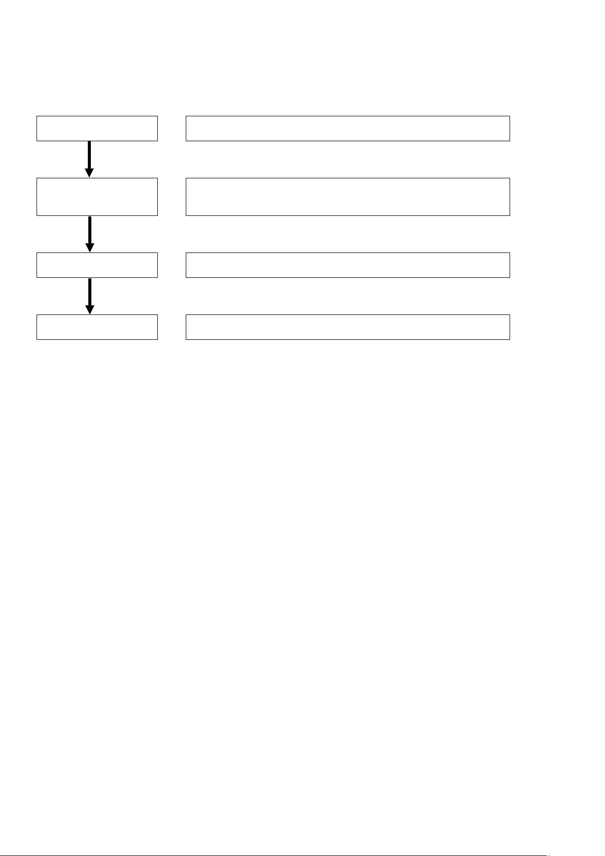
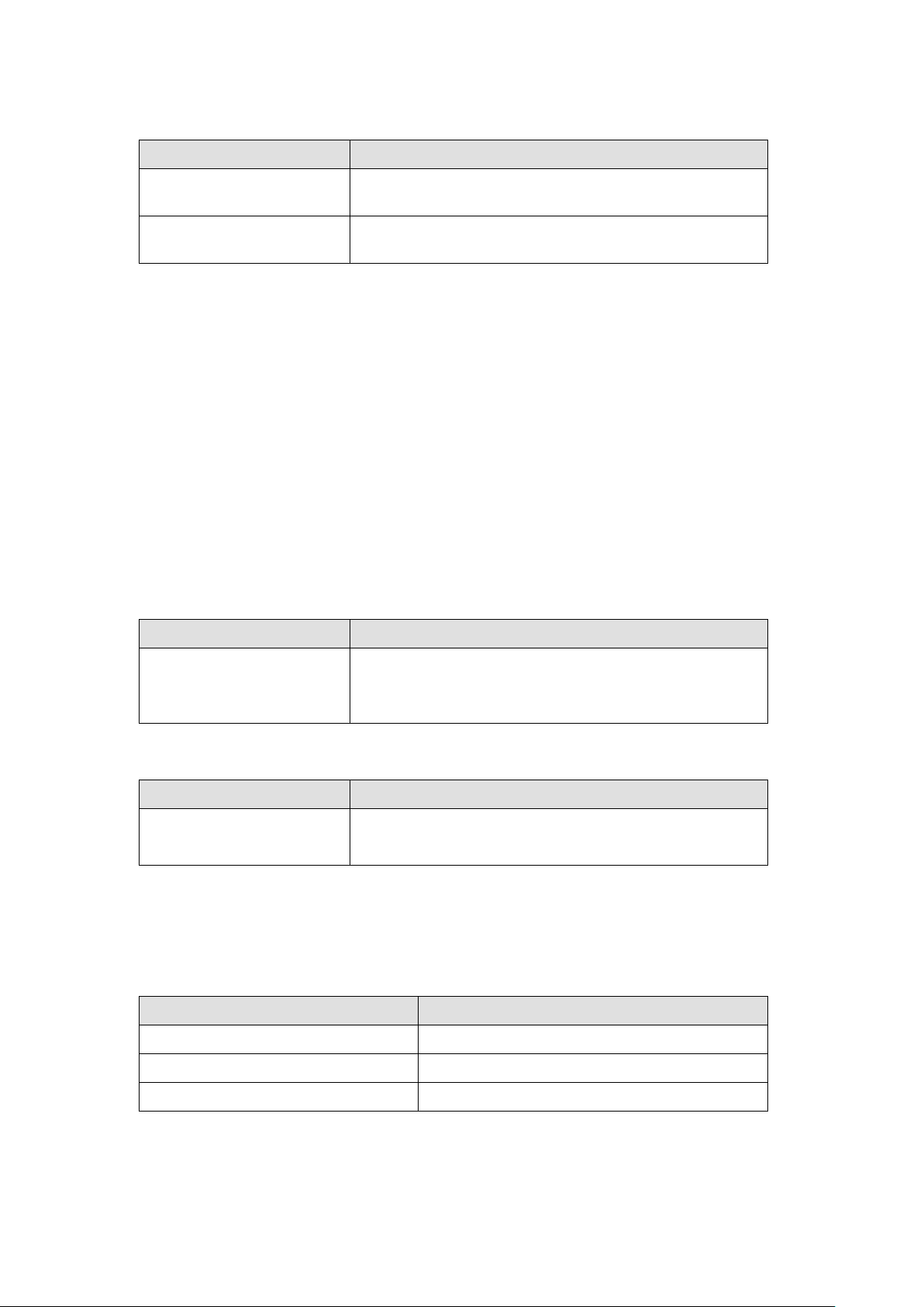
1. Introduction
System design
Provide a guide to determine the appropriate CX-Compolet
communication method for the configuration of the equipment.
Application design
This section presents guidelines for configuring user applications
using tag data links or message communication, based on the
points to remember.
Startup Phase
Shows how to check the operation when starting up the equipment.
Operation Phase
This section presents a guide to trouble shooting methods when
operating the equipment.
This guide provides a guide for facilitating the development of new designs for CX-Compolet devices.
Page 10
10
2. System Design
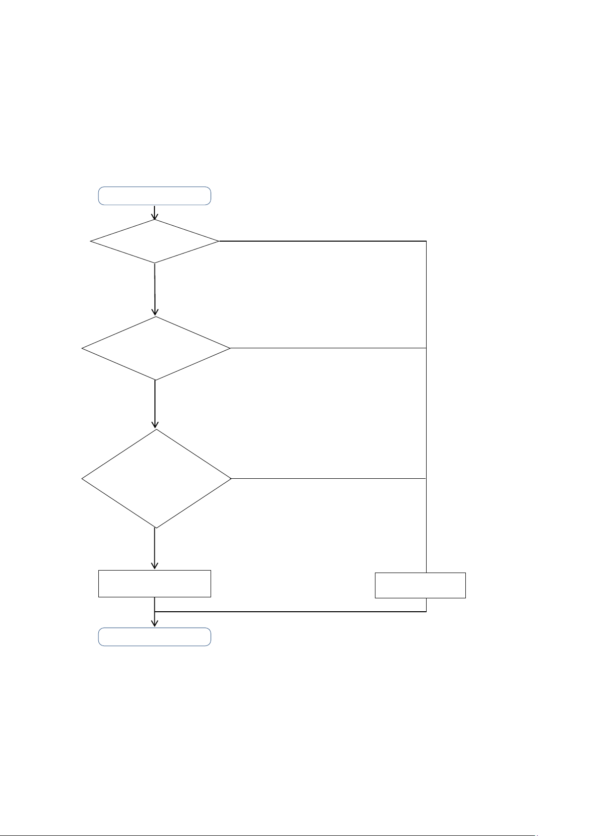
Tag Data Link
Data communications
START
Communication
Data Type?
Read/write DATA with events as triggers
- Write/read the setting parameters
- Read/clear error history and status
Does communication
target device support
tag data link?
YES
END
NO
Tag variable data exchange at regular intervals
- Interlock between processes
- Issue production orders
- Such as Acquire production data.
NO
YES
Data communicati
ons
by Message
Are the number
of connections of tag data
link and communication
bandwidth within
the specification limits?
The system design describes the selection of the optimum communication method (tag data link or message
communication) for the target device and the limitations of each communication method.
2.1. Communication Method Selection Flow
Select the communication method (tag data link, message communication). Determine the
communication method according to the flow chart below.
・ The use of a tag data link is recommended if communication response performance or periodicity is
emphasized, when developing an application to monitor the equipment (line) or to give instructions
to the equipment. The tag data link must keep the used communication bandwidth (PPS) within the
Page 11

11
specified range. Refer to the user’s manual of the unit and set the settings properly.
NJ/NX-series CPU Unit Built-in EtherNet/IP™ Port (Cat. No. W506)
Point
When constructing the instruction system with the tag data link, design with consideration of the
handshake(5.1.3.3 Application handshakes in user applications
Even if the system is mainly data reading/writing triggered by an event, when the data capacity
is large or the event occurs frequently, the communication load and the load on the SYSMAC
Gateway may increase. In addition, the expected response speed may not be satisfied.
Therefore, we recommend designing for the restriction on the use of message communication,
using the tag data link function as the basis.
) in the application.
Page 12

12
2.2. Checking Specifications of Each Communication Method
Function
Protocol
Port number
Remarks
Tag data link
UDP
2222
Fixed value and
communication
Item
Specifications
Number of connections
Up to 384 (same when multiple ports are used)
Number of registrable tag
sets
Number of registrable tags
384
Number of tags per
(7 tags when the tag set includes the Controller status)
Item
Specifications
node
Maximum data size per
connection
In this chapter, the requirements for applications should be designed to be implemented within the
specifications of each communication method described below.
2.2.1. Checking TCP/UDP port to use
SYSMAC Gateway uses the TCP/UDP port numbers shown in the following table. Do not set the same
port number for other applications.
Message
TCP 44818
2.2.2. Checking tag data link specifications
2.2.2.1. Checking number of connections
Check that the maximum value of the following items of the tag data link is not exceeded.
384 (1 connection = 1 tag set)
Up to 8
connection (= 1 tag set)
2.2.2.2. Checking the data size of the connection
unchangeable
Make sure that the data size does not exceed the maximum values of the following items.
Maximum link data size per
Maximum size of 1 tag set 722 words (The Controller status uses 1 word when the tag
*1: To use a data size of 505 bytes or larger, the system must support a large forward open (an optional CIP specification).
The CS, CJ, NJ, NX, and NY-series Units support a large forward open, but before connecting to nodes of other
companies, confirm that the devices also support it.
369664 bytes
1444 bytes*1
set includes the Controller status.)
Page 13
13
2.2.2.3. Checking the data exchange interval
Item
Specifications
separately for each connection in 1-ms increments)
Allowed communications
bandwidth
Item
Specifications
Server: No restriction (depends on the computer memory)
Item
Specifications
Item
Specifications
Number of Open Connection Tasks
Up to 32
Number of Close Connection Tasks
Up to 64
Number of Send Message Tasks
Up to 64
Check the data exchange interval and the communication bandwidth.
Packet interval 1 to 10,000 ms*1 (The packet interval can be set
5000 pps*2 (The heartbeat is included.)
*1: It can be set from 1ms at the shortest, but if the packet interval is short, the timeout is likely to occur depending on the
OS state. Normally, use it at least 50 ms.
*2: The pps means “packets per second”, and indicates the number of packets that can be processed per second.
Point
Communication time variations increase as the data length increases or the number of connections
increases according to the setting of tag data link. Also, communication time variations occur
depending on the type of network card, CPU load, and network load. The extent to which
communication performance is achieved is depending on the usage environment. Be sure to measure
the performance in the actual environment. Set such as the packet interval, time-out monitoring time
to an appropriate value afterward.
2.2.3. Checking message communication specifications
2.2.3.1. Checking number of connections
Ensure that the total number of connections does not exceed the maximum.
Number of connections Client: Maximum connections in total of UCMM and Class
3 = 128
2.2.3.2. Checking data size of connection
Ensure that the data size of the connection does not exceed the maximum.
Data sizes Up to 1988 bytes*1 (Class 3)/496 bytes*1 (UCMM)
*1 These values are the maximum values. The values depend on the data type, variable name, path information, and other
factors according to whether connections are used, R/W direction and the like.
2.2.3.3. Checking number of transactions that SYSMAC Gateway can accept simultaneously
Ensure that the number of processes in the user application does not exceed the maximum value.
Page 14

14
2.3. Checking Compolet Type
Name
Overview
manipulation from a computer
CPU unit
NJCompolet
Compolet for CIP communication with the NJ Series CPU unit
NXCompolet
Compolet for CIP communication with the NX Series CPU unit
Compolet for CIP communication with the NY Series IPC
machine controller
This component performs CIP communications with the
write service
(service ID:0x4C, 0x4D)
Compolet that provides a common IF encompassing the
SYSMAC Compolet type above
as a controller on the computer.
in the SYSMAC Gateway
CIPPortCompolet
Compolet to open/close the SYSMAC Gateway network port
DatalinkCompolet
Compolet to get the tag data link settings and acquire the status
operate the function
Compolet is a Windows software component that facilitates communication between computers and
PLCs. There are two types of Compolet, which are incorporated into the user application according to
the purpose.
・ SYSMAC Compolet that facilitates PLC data read/write or PLC operations
・ SYSMAC Gateway Compolet that retrieves the data for the SYSMAC Gateway installed on the
computer
SYSMAC Compolet Software components that provide the function to simplify PLC
CJ2Compolet Compolet for CIP communication with SYSMAC CJ Series CJ2
NYCompolet
CommonCompolet
controllers that complies with the ODVA specification data types
and supporting industrial standard tag read-
DataAccessCompolet
SYSMAC Gateway Compolet A software component of a computer that provides application
software with operations to acquire and control the data and
status of the SYSMAC Gateway itself, which operates virtually
VariableCompolet Compolet to read and write the value of the variable registered
SgwServiceCompolet Compolet to retrieve the status of the SYSMAC Gateway and
Point
When you use CJ2Compolet/ NJCompolet/ NXCompolet/ NYCompolet/ DataAccessCompolet
(Omron's PLCs are specified), ReadVariableMultiple and ReadRawDataMultiple methods can retrieve
multiple variables with a single command. (For CommonCompolet/DataAccessCompolet
(CipCommon is specified), Compolet reads variable one by one.)
Page 15

15
3. Application Design
This chapter describes the characteristics and usage of tag data links and message communication.
3.1. Using Tag Data Link
Tag data links can be cyclically exchanged data between SYSMAC Gateway and PLCs or between
SYSMAC Gateway and SYSMAC Gateway, respectively, on the EtherNet/IP network.
In a user application, VariableCompolet retrieves the values of the variables reflected on the SYSMAC
Gateway via the tag data link function.
Point
If periodicity is considered important for data exchange of the device, the tag data link should be used
preferentially.
Design the user application in the following steps.
1.
Create a Compolet instance
Create a VariableCompolet instance to connect to the SYSMAC Gateway on the computer.
2.
Enable the VariableCompolet component
Maintain the active state of the component (Active property) until the user application is closed.
Disables the component (the Active property is disabled) and disposes the VariableCompolet instance
when closing the application.
3.
Reading and Writing Variables Registered in the SYSMAC Gateway
・ When communication is high-load, trouble such as timeout is likely to occur. For this reason, set the
interval between several tens of ms and several hundred ms of sleep processing during read and
write processing. The sleep interval is determined according to the system responsiveness.
・ If you use a single Compolet instance from multiple threads, you need to perform exclusive access
control to the instance.
Page 16

16
3.1.1. Creation of Compolet instance
3.1.1.1. Creation of one VariableCompolet
Create one VariableCompolet instance for one user application.
Point
Confirm that the instance is generated correctly by FinsGateway Setting. Confirm that Number of Ports
Being Used for FinsGateway setting is increased by one when the user application is started.
Page 17

17
3.1.2. Validation of VariableCompolet
3.1.2.1. Remain VariableCompolet valid until user application is terminated
The Active property of the VariableCompolet is enabled until the user application is terminated and
remains enabled until the user application is terminated. Disables the Active property of the
VariableCompolet at the end of the user application and disposes of the VariableCompolet instance
(Dispose).
Point
VariableCompolet is enabled or disabled only once for the start and end of a user application.
Enable/disable checks that the number of event ports does not increase or decrease, except at the
start and end of the user application. (See 3.1.1 Creation of Compolet Instance
3.1.3. Reading and writing variable values registered in SYSMAC Gateway
3.1.3.1. Setting of Read/Write processing interval
Set the interval between several tens ms and several hundred ms of sleep processing during read and
write processing. The sleep interval is changed according to the system responsiveness.
3.1.3.2. Reading and writing variables from multiple threads
)
When you read and write variables from multiple threads using a single Compolet instance, you need to
perform the exclusive control in your applications.
Point
Instance members that are not public static (Visual Basic: Shared) of Compolet are not thread-safe.
Page 18

18
3.2. Using Message Communications
For devices on an EtherNet/IP network, CIP communication (issuing CIP commands and receiving
responses) can be performed by executing any Compolet on a user application.
CIP communication is performed using the Compolet (2.3. Checking Compolet Type
the device to be communicated. The figure below shows an example when communicating with the NXseries CPU Unit.
Point
Message communication differs from tag data links in that only tag variables can be used to read and
write memory of a device.
Message communication is suitable for use in event-type communication such as reading errors. The
use of tag data link is recommended if data exchange is in regular intervals.
) corresponding to
The following steps are used to design.
1.
Create Compolet instances.
Remember to assign a Compolet Instance to a Node.
2.
Set timeout monitoring period.
Set the timeout monitoring period (ReceiveTimeLimit property) to 2 seconds or longer.
3.
Open a connection.
Keep the connection open until the application finished. When closing the application, also close the
connection, and dispose the Compolet instances.
Point
If you want to open connections simultaneously from multiple threads (Set Active property
Enabled), you need to perform the exclusive control to open connections in your applications.
4.
Perform message communication.
Set several tens ms and several hundred ms of sleep processing during communications and
set the interval for each message communication.
Add an appropriate CIP communication every 5 seconds if you set 10 seconds or more intervals.
SYSMAC Gateway implements a standard specification for CIP communication that disconnects
connection when there is no communication with a target for 10 seconds. To prevent unintended
disconnection, appropriate CIP communication must be performed within 10 seconds.
Page 19

19
Point
When communicating by a single Compolet instance from multiple threads, you need to
perform the exclusive control in your applications.
3.2.1. Creation of Compolet instance
3.2.1.1. When creating Compolet instances, remember to assign a Compolet Instance to a PLC Node.
Each Compolet should correspond to each Node (Controller or SYSMAC Gateway installed in
computer). Assigning one instance to one node prevents simultaneous access from multiple Compolet
instances.
Point
The Explicit Message Task Monitor on the SYSMAC Gateway allows you to check Number of
Established Connections. Confirm that the number of nodes to be connected is the same as the
number of connections displayed. If there is an inconsistency, extra connections may be left.
Page 20

20
3.2.2. Setting timeout monitoring period
3.2.2.1. Set timeout monitoring period (ReceiveTimeLimit Property) to 2 Seconds or Longer.
When multiple Compolet instances are used in user applications that handle multiple nodes, there is
a risk that the response received by Compolet will be delayed due to the increased communication
load. In order to reduce this risk, ensure to set long timeout monitoring period.
Point
Like the SYSMAC Gateway, the timeout monitoring period is set to 2 seconds or longer, which is
the default Response Monitor Time of Sysmac Studio, which is the software for communicating
with the controller.
In the source code of the user application, check the timeout monitoring period set in the
ReceiveTimeLimit property of the Compolet.
The MaxExecuteTimeSpan property of Compolet can be used to acquire the maximum
communication time. When timeout occurs during operation, the timeout monitoring period is set
based on the maximum communication time acquired.
Page 21

21
3.2.3. Opening connections
Code
Level
Message
10001
Information
The open processing was accepted.
Confirm that the number of code 10001 which exceeds
3.2.3.1. Keeping the connection open until the application finished.
Design the connection to remain open until the end of the user application. When closing the application,
also close the connection, and dispose the Compolet instances.
Point
The connection is maintained by the communication of the opened connection.
If the communication is not performed, the connection is automatically disconnected.
Once the connection is opened, by maintaining it, to re-open unnecessary connections is suppressed.
In addition, the processing load inside Compolet is reduced.
When SYSMAC Gateway is accepted an open connection request, an event (10001) of a request
connection in the event history of the Explicit Message Task Monitor is recorded. When composed of
multiple nodes, you can confirm the event for the number of nodes. When registered the number of
events which exceeds that of nodes, check that of connections per node.
that of nodes are not displayed.
Page 22

22
3.2.3.2. One by one opening connections for multiple nodes
Design the connections for a multiple node to open connections one by one when a user application
opens connections for each node.
Point
Upon receipt of the opening request from Compolet, the SYSMAC Gateway performs the connection
opening process. User application should be designed to avoid overlapping opening requests because
SYSMAC Gateway performs only one connection opening process at a time.
After confirming the opening process is completed, perform the following connection opening process.
The Explicit Message Task Monitor enables you to check the current connection opening requests
SYSMAC Gateway accepted. Confirm the number of open connection tasks, which represents the
number of open connection requests, is not more than two.
Page 23

23
3.2.4. Performing message communications
Code
Level
Message
10002
Information
No response was received within the receive timeout.
10003
Information
Receive timeout has almost occurred.
3.2.4.1. Control exclusively for multiple simultaneous access to a single Compolet instance.
When accessing a single Compolet instance using multi-threaded, you need to perform the exclusive
control in your applications.
Alternatively, design to perform an access to one Compolet instance from one thread only.
3.2.4.2. Setting of communication processing interval
Set the interval for communication by putting tens to hundreds of milliseconds of sleep during
communication.
Point
Check the communication load state on the Explicit Message Task Monitor and adjust the interval so
that the reception timeout does not occur.
The number of send message tasks and the status of communication timeouts can be checked on the
Explicit Message Task Monitor. If a communication timeout occurs or is likely to occur, the following
events are recorded in the event history.
Page 24

24
3.2.4.3. Setting the communication processing interval of the connection open state in under 10
Code
Level
Message
The connection for message communications was
closed.
10001
Information
The open processing was accepted.
Confirm there is no unintended disconnection.
seconds
When the communication interval exceeds 10 seconds, the process of performing appropriate
message communication should be added once every 5 seconds.
When an interval of more than 10 seconds is generated in the event of message communication in
the connection open state, an appropriate message communication process should be added.
Additional Information
As a general specification of EtherNet/IP, when there is no communication for a certain period, the
connection is automatically disconnected. According to this specification, SYSMAC Gateway
disconnects the connection if the user application does not request transmission for more than 10
seconds.
When CIP communication is executed after the connection is disconnected, the Compolet automatically
performs reconnection.
Point
When there is no communication for a certain period and the connection is closed, the following two
events are recorded for each close in the event history on Explicit Message Task Monitor.
If the events are confirmed, check countermeasures of 3.2.4.3 Setting The Communication
Processing Interval In The Connection Open State In Under 10 Seconds again.
150 Warning
Page 25

25
4. Startup Phase
This chapter describes the procedures and notes about tag data links and message communication during the
system startup.
4.1. Using Tag Data Link
Monitor the communication status of the tag data link in the Network Configurator. Connect the Network
Configurator online, select the device to be checked, right-click to display the pop-up menu, and select
Monitor.
The Monitor Device Dialog Box will be displayed. Then, check as described in the next section.
Additional Information
If a communications error occurs during monitoring, the dialog box will continue to show the last
information that was collected.
To start monitoring again, close the Monitor Device Dialog Box, and then open the Monitor Device
Dialog Box again.
Page 26

26
4.1.1. Checking connection status
Status
Description
Ok
Normal data exchange is possible.
Different sizes are set for the network variables and the tag
occurs.
occurs.
occurs.
4.1.1.1. Checking tag status
Display Tag Status Tab Page and check the tag resolution status.
This tab page displays if the tag settings for each tag for tag data links are set so that data can be
exchanged.
The following status is displayed depending on the status that is set.
Processing
to solve
Size error
Not exist A network variable set in the specified tag setting does not exist.
Refresh type
error
The variables with tags are being resolved.
When the resolution is completed normally, a connection will be
established, and the data exchange will start.
settings.
A connection will not be established for a tag for which this error
A connection will not be established for a tag for which this error
(1) The Controller network variable cannot be written because of
the Constant attribute.
(2) The I/O direction that is set in the tag data link settings does
not agree with the I/O direction of the network variable.
A connection will not be established for a tag for which this error
If the status is not “Ok”, set the tag data link or the network variable correctly.
Page 27

27
4.1.1.2. Checking connection status
Display Connection tab and check the Connection status.
Information about the target node that acts as the originator is displayed.
If all the tag data link connections with the node in the monitor are established and normal, this information
is displayed in blue. However, if any connection is broken it is displayed in red. However, this
information is displayed in gray if the connection of a node in the monitor is stopped.
In addition, in the Connection Status Area, the Status Column shows the current status of each
connection that is set as the originator. This information can be used to identify the cause of tag data link
errors.
Refer to one of the following manuals for details of connection status information.
NJ/NX-series CPU Unit Built-in EtherNet/IP Port User’s Manual (Cat. No. W506)
NY-series IPC Machine Controller Industrial Panel PC / Industrial Box PC Built-in EtherNet/IP Port User’s
Manual (Cat. No. W563)
Page 28

28
4.2. Using Message Communications
4.2.1. Checking communication load of Compolet/SYSMAC Gateway
The Explicit Message Task Monitor can monitor the communication load of the Compolet and SYSMAC
Gateway.
More information about using the Explicit Message Task Monitor can be found in the SYSMAC Gateway
Help. SYSMAC Gateway Help - SYSMAC Gateway - Troubleshooting - How to use Explicit Message
Task Monitor
4.2.1.1. Checking number of internal processes in SYSMAC Gateway
Check the number of SYSMAC Gateway internal processes on the Explicit Message Task Monitor. The
following three tasks can be checked.
・ Open Connection Tasks
Shows the number of connection requests received by the SYSMAC Gateway.
・ Close Connection Tasks
Shows the number of disconnect requests received by the SYSMAC Gateway.
・ Send Message Tasks
Shows the number of send messages that SYSMAC Gateway is processing at the same time.
Point
You can check the change in the number of processes using a graph. Confirm that the design does
not exceed the upper limit of the number of processes.
Refer to 2.2.3.3. Checking number of transactions that SYSMAC Gateway can accept simultaneously
4.2.1.2. Checking number of connections
Confirm each number of connections of UCMM and Class3 that the SYSMAC Gateway has established
as clients. For the maximum number of connections, refer to 2.2.3.1. Checking number of connections
Point
If the number of connections is increasing, refer to 3.2 Using Message Communications
.
.
.
Page 29

29
5. Operation Phase
Meaning
Normal
Description
The specified IP address is assigned correctly.
The port is correctly open with the status "Open”.
“5.1.1.2 Checking Windows communication status”.
Meaning
Service has not been started.
Description
The specified IP address is assigned correctly.
The status is not displayed. The communication service may have not been started.
Action
Check if the SYSMAC Gateway service has been started.
Meaning
Network card selection error
Description
The network card is not selected correctly.
Check if the specified network card is available.
Meaning
Cable disconnection error
This chapter describes the problems that may occur during operation of devices, possible causes, and
troubleshooting.
5.1. Investigation Flow
This section describes the flow of investigations for detailed confirmation of phenomena and separation
of causes of major problems that occur when operating devices.
In section 5.1.1 is described as following: common problems, assumed factors, and troubleshooting for
tag data link/message communication.
From section 5.1.2 to 5.1.4 are described as following: the tag data link.
In section 5.1.5 is described as following: the message communication-specific items.
5.1.1. Communications which cannot be performed with the target device
Use the following procedure to grasp the situation and identify the cause if communications cannot be
performed with the target device.
1. Is the SYSMAC Gateway port open correctly?
2. Are the communications being performed in the Windows level?
3. Can SYSMAC Gateway perform the communications?
5.1.1.1. Checking open state of SYSMAC Gateway port
Check the condition of the applicable port on the SYSMAC Gateway Console.
1. Start the SYSMAC Gateway Console.
2. Check the parameter display area of the applicable port ID in the network port.
・
・
Action When the communications cannot be performed even if the port is correctly open, refer to
・
・
Action ・ Check if the network card that you want to use is set in the network port property page.
・
Page 30

30
Description
No IP address is allocated to the specified network card.
Action ・ Check if the IP address is allocated correctly.
Check if a normal response is returned from the connected device to the ping command.
Meaning
The IP address was changed.
Description
A different IP address from the one specified in the setting is allocated.
Check if the network setting to use DHCP for getting the IP address is made.
・
Action ・ Check if the IP address that you set has been changed.
・
Additional Information
If you set the Automatically open port at startup of the Ethernet Port Properties in SYSMAC Gateway
Console, SYSMAC Gateway may perform the opening process before Windows recognizes the
network card.
In order to execute the open process in the user application, set the Startup Type of CIPCore service
the delay start, or disable Open port automatically at startup and then you perform open port process in
your applications.
5.1.1.2. Checking Windows communication status
Check the following when the communications cannot be performed even if the port is open for SYSMAC
Gateway.
1. Check if the communications can be performed with the connected device by using the ping command.
1-1. Check if the connected device returns a response to the ping command in the Windows
command prompt.
1-2. When no response is returned to the ping command, check the network status and connected
device as shown below.
Is the power supply to the connected device ON?
Is the correct IP address is set for the connected device?
Is the correct network address is set for the IP address of the connected device?
Are the problems solved by changing the connection cable, network card, and switching
hub status?
2. Check for the firewall settings.
2-1. Check if the CIPCore.exe, which is the execution file of SYSMAC Gateway in the firewall
Page 31

31
settings.
2-2. Register CIPCore.exe as an exception process of the firewall. (both for UDP and TCP)
Refer to the Firewall Settings in the Installation Guide for details.
5.1.1.3. Checking communication status of SYSMAC Gateway
After confirming the Windows communication status, use the message communication function of
SYSMAC Gateway to check the communication.
1. Check if the tags of the connected device can be monitored by the tag monitoring function.
Only the network variables can be monitored.
For information about using the tag monitoring function, refer to the SYSMAC Gateway Help.
SYSMAC Gateway Help - Tag Monitor
2. Confirm that communication can be performed correctly in the message communication test.
Refer to SYSMAC Gateway Help on how to test the message communication.
SYSMAC Gateway Help - SYSMAC Gateway - Troubleshooting - Message
Communications Test
Page 32

32
5.1.2. Tag data Link which cannot be established properly
Use the following procedure to grasp the situation and identify the cause if the tag data link has not been
correctly established although the basic communications have been established with the target Controller.
1. Are the data link settings correct?
2. Haven't any problems been detected in the SYSMAC Gateway level?
5.1.2.1. Are the data link settings correct?
Check if the connection to SYSMAC Gateway has been established using Network Configurator or
SYSMAC Gateway Troubleshooter.
1. If the connection for the tag data link has not been established, solve the problem based on the
instructions displayed in the Troubleshooter.
SYSMAC Gateway Help - SYSMAC Gateway - Troubleshooting - Troubleshoot
2. Also, check the following.
2-1. Are the tag settings and data link settings correct?
2-2. When the settings are changed in the Network Configurator, were the settings downloaded to
all of the devices?
2-3. For the data link settings between NJ/NX/NY-series Controller and SYSMAC Gateway, are the
tags of the NJ/NX/NY-series Controller CJ2-compatible alignment?
Refer to SYSMAC Gateway Help on how to exchange data with the NJ/NX/NY controller.
SYSMAC Gateway Help - SYSMAC Gateway - Using SYSMAC Gateway - Precautions Data exchange with NJ/NX/NY Controllers
2-4. When multiple ports are used, make sure that the settings for all ports are correct.
Refer to SYSMAC Gateway Help for instructions on extending Ethernet ports.
SYSMAC Gateway Help - SYSMAC Gateway - Tag Data Link - Setting for Extending
Ethernet Ports
5.1.2.2. Checking problems detected by SYSMAC Gateway
Check the Windows Event Viewer for problems detected by SYSMAC Gateway.
The Windows Event Log, which is recorded in the Windows Event Viewer, records the internal status
changes and problems detected by the SYSMAC Gateway. You can detect problems by checking
the Windows event log.
Refer to SYSMAC Gateway Help for the general information and check procedure of the
windows event log.
SYSMAC Gateway Help - SYSMAC Gateway- Troubleshooting - Checking the Windows
Event Log
Page 33

33
5.1.3. Not applied data regardless of the established tag data link connection
Use the following procedure to grasp the situation and identify the cause if the data is not applied although
the basic communications have been established with the target Controller and the tag data link
connection has been also established.
1. Is the CIPCore excluded from the filtering target in the firewall settings?
2. Doesn't the network card filter the messages?
3. In the application program, is the handshake taken into account in the programming?
5.1.3.1. Checking firewall settings
Depending on the firewall settings, it may look as if the data is not applied although the tag data link
is established. When receive data of tag data link is filtered by the firewall setting, the following
symptoms appear.
When monitoring a data link of which SYSMAC Gateway is the originator on Network
Configurator, it looks as if the data is not updated although the connection is normally
established.
When monitoring using the Troubleshooter, it looks as if the connection is opened and closed
in a 10-s cycle.
When checking the event log, it looks as if a timeout occurs for the originator once every 10 s
and the connection is re-opened.
1. Exclude CIPCore.exe from the filtering targets. Refer to the Firewall Settings of the installation
guide for concrete setting procedures.
2. By changing or version-upgrading the antivirus software, the firewall settings may be initialized
or filtering of the unintended data. Disable or uninstall the antivirus software to check for the
impact of the antivirus software.
5.1.3.2. Checking network cards
Check whether the network card driver is up to date.
Depending on the parameter settings of the network card driver, the multicast data filtering function may
work when the communications load is heavy.
1. Check the network card specifications and that the correct parameters are set.
2. If the parameter change does not resolve, apply the network card of the different vendor and check
the state.
Page 34

34
5.1.3.3. Application of handshakes in user applications
The tag data link periodically sends data at high speed. Even if a communications error occurs, the
transmission is not retried. And the data for the next cycle is sent as the latest data.
1. When transmitting data with reliability, the communication handshake should be applied to the user
application.
"data with reliability" means that the data is reliably reached by flag processing between application
and controller.
Image of the communication handshake
2. Check if the target data is not re-written from the application separately from updates in the tag data
link.
Page 35

35
5.1.4. Disconnection of tag data link
Use the following procedure to grasp the situation and identify the cause if the tag data link connection
is closed although the basic communications have been established with the target Controller and the
tag data link connection has been also established.
1. Confirmation of communication environment and computer environment
2. Confirmation of communication cycle
3. Confirmation of timeout monitoring period
5.1.4.1. Confirmation of communication environment and computer environment
The following communications environment factors may cause timeouts. Check the environment to see
if the frequency of the phenomena is increased or reduced by changing the environmental factors.
Message communications errors may be caused by a contact failure of a cable or by using a non-
standard cable.
Noise in the communications cable and target device may cause message communications errors.
Check the performance, settings, and arrangement of the switches, routers, hubs, and other items.
Depending on the performance and settings of switches, routers, hubs, and other items, the
communications performance may be lowered, or the messages may be filtered. For example, if
IGMP filter is set, multicast packets of the tag data link are not be received, and the timeout occurs.
Changing the network card may improve the processing speed and reduce the timeouts.
Depending on the driver software version of the network card or driver parameter settings, data
capturing failures may occur.
The computer may have some error such as disk error and memory error.
Confirming the latest Windows operating system update
If there are some patterns on the timing when the tag data link is disconnected, the phenomenon may
occur by the influence of the function that is being executed at the time.
For example:
The phenomenon occurs at a similar time in the morning. In this case, some processing may
be executed periodically at the time in the computer.
The phenomenon occurs when a certain device or program is started.
Check antivirus software
The communications performance may be lowered, or the messages may be filtered by some
function such as antivirus software that checks the receive messages.
Page 36

36
5.1.4.2. Packet interval confirmation
If update data is not received within the monitoring time set to detect a timeout, the tag data link regards
it as a timeout, delete a connection, and re-establish the connection.
The Windows OS is not a realtime OS. Therefore, SYSMAC Gateway may need to wait for a long time
when heavy load is imposed on the OS processing.
Confirm that the packet interval is set to 50 ms or more.
Although the minimum data packet interval of the tag data link is 1 ms, timeouts may often occur
depending on the OS status if the packet interval is short. Normally, set the interval to 50 ms or
longer.
Point
Communication time variation increases as the data length increases or the number of connections
increases according to the setting of tag data link. Also, communication time variations occur
depending on the type of network card, CPU load, and network load. The extent to which
communication performance is achieved is depending on the usage environment. Be sure to measure
the performance in the actual environment. Set such as the packet interval, time-out monitoring time
to an appropriate value afterward.
5.1.4.3. Checking timeout monitoring time
If a connection timeout occurs, verify that:
Check if the problem is solved by extending the monitoring time to detect the timeout.
The connection is closed and automatically re-opened when a timeout occurs. If this re-opening
request is generated, closing and re-opening processing increase communication load of SYSMAC
Gateway, and the timeout will occur more easily in a chain reaction.
Additional Information
The packet of tag data link may not have been sent within the time required for the application due to
the high PLC load. Check the interval time between packets using the network protocol analyzer (such
as Wireshark). If the timeout monitoring time cannot be increased, consider reducing the load on the
PLC.
Page 37

37
5.1.5. Error message communication
Use the following procedure to grasp the situation and identify the cause if a message communication is
error with the target device.
1. Is it possible to send a message individually while the application is not running?
2. Is the exclusive control taken into account for multi-thread processing?
3. Isn't the application terminated or stopped by application errors during debugging?
4. Is the monitoring time to detect a timeout proper?
5.1.5.1. Is it possible to send a message individually while the application is not running?
Use the procedure for 5.1.1. Communications cannot be performed with the target device to check
if a problem has occurred.
Check if the communications can be performed with the utility provided by SYSMAC Gateway.
1. Can the tags be monitored by on the tag monitoring on SYSMAC Gateway?
2. Can the communications be performed by the CIP communications test?
Select Communications Test from the control panel of SYSMAC Gateway Console.
Set the IP address of the target device to check for the CIP communications and click the Start
button.
3. Check that the communications are performed by the sample program in use if you use CX-Compolet.
Select the sample program from [Omron] - [CX-Compolet] - [Samples] of the Windows menu and
build and execute them.
5.1.5.2. Is the exclusive control taken into account for multi-thread processing?
The API and the CX-Compolet functions provided by SYSMAC Gateway SDK are not thread-safe.
As described in
instance, if you use them in the multi-thread environment, you need to perform the exclusive control
in your applications.
5.1.5.3. Isn't the application terminated or stopped by application errors during debugging?
If the process is interrupted or stopped due to an application error during debugging of a user application,
the memory area used by the SYSMAC Gateway may not be released and the communication process
may be affected.
If the following conditions are found, the application using the SYSMAC Gateway and the service of the
SYSMAC Gateway are all terminated, and then the communication status is checked by starting again.
The program was aborted without exit processing after debugging.
The application was terminated due to an error without exit processing during development of the
application.
3.2.4.1 Control exclusively for multiple simultaneous access to a single Compolet
Page 38

38
5.1.5.4. Is the monitoring time to detect a timeout proper?
Perform enough evaluation for the timeout monitoring detection time in your system and set the
optimum time before starting operation of the device.
Set a time out period in the user application, refer to 3.2.2 Setting timeout monitoring period
.
Additional Information
The response time depends on the number of relay stations.
The timeout monitoring time should be added approximately 5 seconds to each relay station.
Page 39

39
6. Checking for Errors and Troubleshooting
This chapter describes how to check for errors and specific troubleshooting.
6.1. Checking Methods of Error
6.1.1. Confirmation by Windows Event Viewer
Start the Windows Event Viewer and select System. The SYSMAC Gateway's communications service
log entries are indicated with "CIPCore" as the source.
The following is an example of filtering with the event source "CIPCore”.
In the Windows Event Viewer, you can view event details, by selecting Details tab in the window.
The following is an example of detailed data for event 264. From the AREA:OPEN record, it can be
confirmed that the reception timeout occurred when the connection was opened.
Additional Information
You may find out the causes of the CIPCore errors by the following checks.
- Do application operations which are recorded in Application of Windows Event Viewer work properly?
- Are any network card errors recorded?
6.1.2. Confirmation by the monitor device function of the network configurator (only tag data link)
Connect the Network Configurator online, select the device to be checked, right-click to display the popup menu, and select Monitor.
Page 40

40
Code
Message
Cause and troubleshooting
The open processing was not
Troubleshooting: Check the number of Open Connection
to avoid
concentration of connections.
The send processing was not
to avoid
concentration of send processing.
The close processing was not
to avoid
concentration of close processing.
was requested
The network port of the SYSMAC Gateway is set to the
CIPPortCompolet in a user application.
connection for message
the previously accepted connection
connection opening process is completed.
The connection for message
Troubleshooting: The connection is automatically and
temporarily closed inside the Compolet and the open
sending interval is no longer than 10 seconds.
The available number of
Troubleshooting 1: Check the number of established
6.2. Checking Details of the Windows Event Log and Troubleshooting
6.2.1. Error caused by message communication
144
accepted.
145
accepted.
146
accepted.
148 The processing
when the port was not open.
Cause: Request for establishment processing exceeded the
number of Open Connection Tasks that can be accepted.
Tasks with the Explicit Message Task Monitor
Cause: Request for send processing exceeded the number
of Send Message Tasks that can be accepted.
Troubleshooting: Check the number of Send message tasks
with the Explicit Message Task Monitor
Cause: Request for close processing exceeded the number
of Close Connection Tasks that can be accepted.
Troubleshooting: Check the number of Close Connection
Tasks with the Explicit Message Task Monitor
Cause: An attempt was made to communicate messages
while the SYSMAC Gateway network port was not opened.
"Automatically open port at startup”. However, Windows was
unable to recognize the LAN card and the port could not be
opened when the communication service was started.
149 A timeout occurred when opening a
communications.
150
communications was closed.
151
connections has been exceeded.
Troubleshooting 1: Starting the SYSMAC Gateway Console
and manually opening the network port.
Troubleshooting 2: Opening the network port using
Cause: When the SYSMAC Gateway accepts the opening of
multiple connections, it performs the opening of connections
one by one from
request. Although the SYSMAC Gateway accepted multiple
connection opening requests, there was a connection task
that did not complete within the timeout monitoring period (5
seconds).
Troubleshooting: When opening multiple connections in an
application, design the application to perform the following
connection opening process after the appropriate
Cause: Sending message interval exceeds a certain time (10
seconds) at any connection.
process is executed again.
If this warning occurs in multiple connections, ID: 149
warning may occur. Execute any communication so that the
Cause: The number of connections reached the maximum
number (128) of connections that can be established.
Page 41

41
connections using the Explicit Message Task Monitor to
make sure whether the number of connections opened by
tion is closed,
before closing.
period to 2
seconds or longer.
of multiple connections, it establishes the opening of
connections one by one from the previously accepted
connection request. Although the SYSMAC Gateway
connection task that did not complete within the timeout
connection opening process after the optional connection
opening process is completed.
Setting the communication
seconds.
so that sending message requests are not concentrated.
Code
Message
Cause and troubleshooting
of on-path device including targets and switches.
devices.
the user application is too many or not.
Troubleshooting 2: When the user applica
make sure that the Active property of the Compolet is false
264 Receive timeout has occurred. Cause 1: Short timeout monitoring period
Troubleshooting 1: Set timeout monitoring
Cause 2: When the SYSMAC Gateway accepts the opening
accepted multiple connection opening requests, there was a
monitoring period (5 seconds).
Troubleshooting 2: When opening multiple connections in an
application, design the application to perform the following
Cause 3: Event ID150 occurs in multiple connections at the
same time and a number of open processing are in
6.2.2. Error occurring in tag data link
118 Timeout detected for the originator
data link.
concentration for a short period.
Troubleshooting 3: Execute the troubleshooting for event ID
150, and refer to
processing interval of the connection open state in under 10
Cause 4: Heavy communication load of SYSMAC Gateway
due to concentrated sending message requests.
Troubleshooting 4: Increase the sending message interval
Cause 1: Cable disconnection or Turn off the power to the
target or switch.
Troubleshooting 1: Check the power and cabling conditions
Cause 2: Packet loss on-path due to network communication
load
Troubleshooting 2: Increase the connection timeout value or
the RPI. Or review the network environment and network
3.2.4.3.
Page 42

42
Code
Message
Description
for open connection from a client application.
No response was received within the
Occurs when a response for message
application do not concentrate.
Occurs when a response for message
timeout specified by the client application has
application do not concentrate.
6.3. Checking Events Occurring in SYSMAC Gateway
Check the event history on the Explicit Message Task Monitor to check the status.
In addition to Windows events described in
6.2 Checking details of the Windows Event Log and
Troubleshooting, the following information is displayed.
10001 The open processing was accepted. Occurs when SYSMAC Gateway accepts a request
10002
receive timeout.
10003 Receive timeout has almost occurred.
communication is received after the receive timeout
specified by the client application has elapsed.
Check receive timeout. Also, review the process so
that requests for sending messages from the user
communication is received after 90% of the receive
elapsed.
Check receive timeout. Also, review the process so
that requests for sending messages from the user
Page 43

43
 Loading...