

Page 1
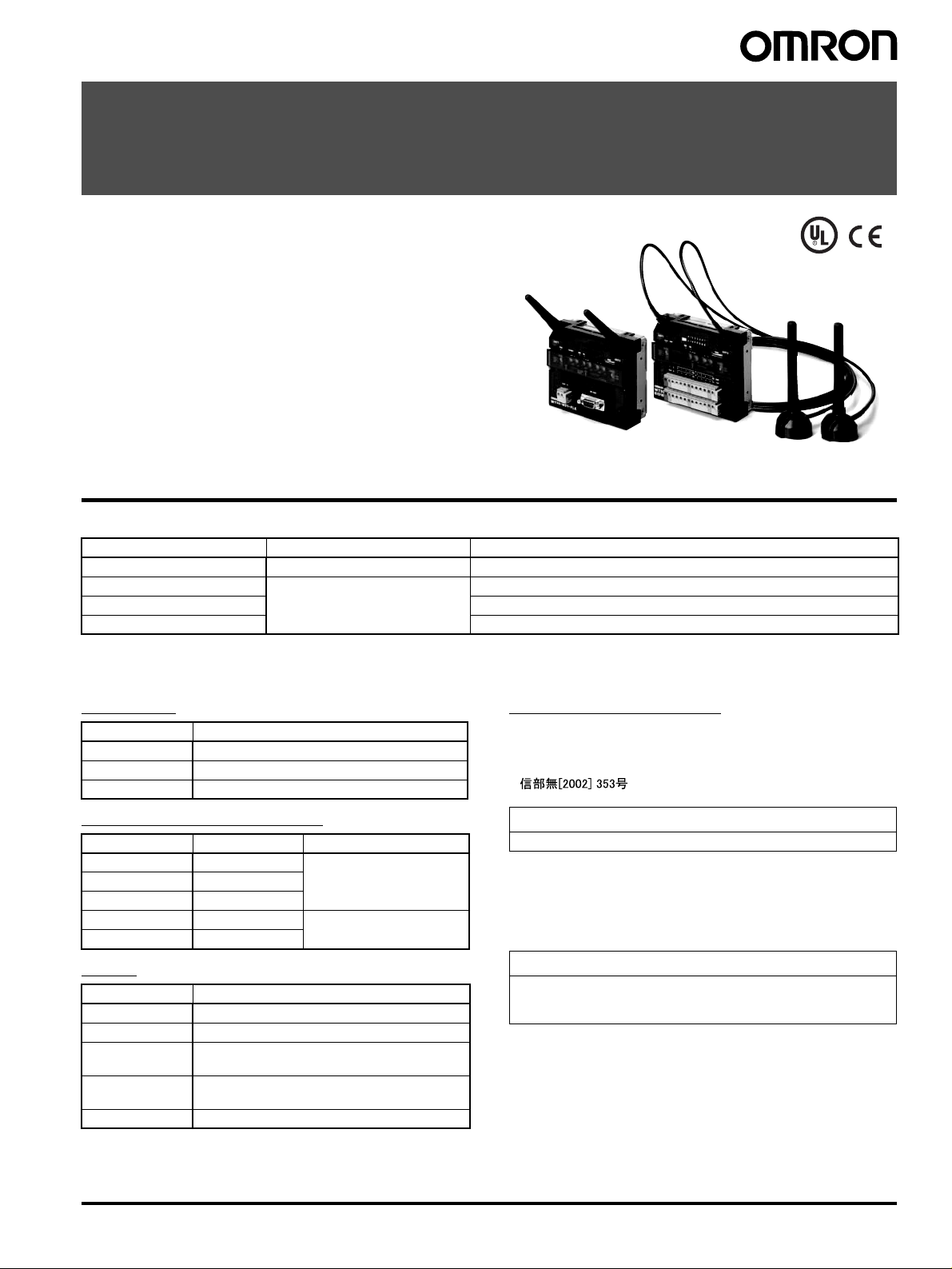
FA Wireless SS Terminals
WT30
Construct a Wireless System for ON/OFF
Data Collection That Is Ideal for Monitoring
Production Site Equipment
• Wireless Slave Station equipped with I/O.
• Height of 90 mm and DIN Rail mounting enables installation in
control panels.
• Easily check wireless communications status from indicator
display.
• I/O Slave Stations can also be used as Slave Stations in WD30
systems.
• Conforms to radio wave standards for Japan, China (pending),
USA, and Europe.
Ordering Information
■ List of Models
Wireless Unit model Type Specifications/No. of I/O points
WT30-M01-FLK Serial master RS-232C
WT30-SID16 I/O slaves 16 DC inputs (NPN/PNP)
WT30-SMD16 8 DC inputs (NPN/PNP) + 8 transistor outputs (NPN)
WT30-SMD16-1 8 DC inputs (NPN/PNP) + 8 transistor outputs (PNP)
Note: An Antenna and Mounting Brackets are not included with the Wireless SS Terminal.
■ Accessories
Antennas
Model Type
WT30-AT001 Magnet-base Antenna (2 antennas per set)
WT30-AT002 Flat Diversity Antenna (1 antenna)
WT30-AT003 Pencil Antenna (2 antennas per set)
Communications Cables
Model Length Application
XW2Z-0100U-3 1 m For personal computer
XW2Z-0200U-3 2 m
XW2Z-0500U-3 5 m
XW2Z-0200U-5 2 m Cross cable for PLC
XW2Z-0500U-5 5 m
Other
Model Type
WT30-FT001 DIN Rail Mounting Bracket (for TH35-7.5)
WT30-FT002 DIN Rail Mounting Bracket (for TH35-15)
WT30-FT003 Surface Mounting Bracket (screw-mounting)
(2 brackets per set)
WT30-FT011 Flat Diversity Antenna Mounting Brackets
(with magnets)
WT30-CA2M Antenna Extension Cable (1 cable, 2 m)
Applicable Standards
• FCC part 15.247 (USA)
• EN 300 440-2 (Europe)
• ARIB STD-T66 (Japan)
• (China) (approval pending)
Conformity to Safety Standards
Always use a Class 2 power supply to conform to UL standards.
Main Class 2 Power Supplies
OMRON Switching Power Supplies
• S8VS (15 W, 30 W, 60 W type)
• S82K (15 W, 30 W, 50 W, 90 W type)
Conformity to EN Standards
Use a DC power line less than 3 m to conform to EN standards. If a
power line of 3 m or longer is required, extend the length at the
Switching Power Supply’s primary side (i.e., the AC power line).
Applicable Countries
Wireless standards have been met for the following countries. The
product cannot be used in any other countries.
Austria, Belgium, Cyprus, Czech Republic, Denmark, Estonia,
Finland, France, Germany, Greece, Hungry, Iceland, Ireland, Italy,
Japan, Latvia, Lithuania, Luxembourg, Malta, Netherlands, Norway,
Poland, Portugal, Slovakia, Slovenia, Spain, Sweden, Switzerland,
UK, USA
FA Wireless SS Terminals WT30 1
Page 2
Specifications
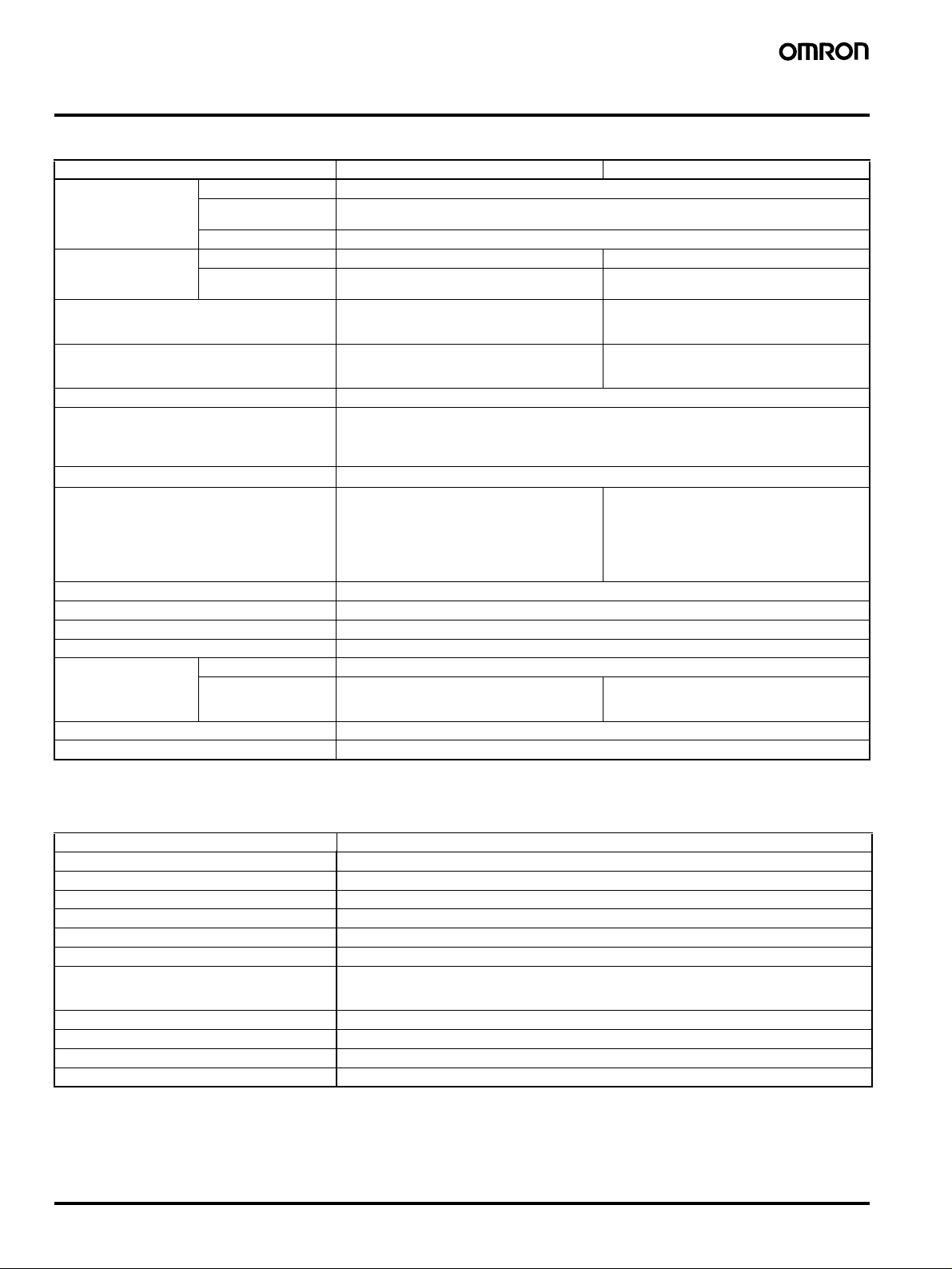
■ Ratings
Item WT30-M01-FLK Serial Master WT30-SID16/SMD16/SMD16-1 I/O Slaves
Power supply
(wireless
communications
power supply)
Error output/output
power supply
(for output circuits)
Insulation resistance 20 M
Dielectric strength 1,500 V AC for 1 min between power supply
Noise immunity IEC61000-4-4. 1 kV (power supply line)
Vibration resistance (See note 2.) JIS C0040
Shock resistance
Ambient operating temperature
Ambient operating humidity 25% to 85% (with no condensation or icing)
Ambient environment No corrosive gases
Storage temperature
Protective structure IP20
Terminal construction Power supply and I/O Screwless terminal block (Phoenix Contact FFKDS/V1-5.08 or equivalent)
Safety standards UL: UL508 (Listing)
Weight 330 g max.
Note: 1. Provide a power supply of at least 15 W, considering the inrush current generated at startup.
2. Use the WT30-FT003 Surface Mounting Bracket when installing the WT30 in environments subject to vibration.
Rated voltage 24 V DC
Allowable voltage
range
Power consumption 3 W max. (See note 1.)
Rated voltage --- 24 V DC
Allowable voltage
range
Serial D-sub, 9-pin (female) Inch screws (OMRON
20.4 to 26.4 V DC
--- 20.4 to 26.4 V DC
Ω min. (at 100 V DC) between the power
supply and chassis
and chassis
Frequency: 10 to 55 Hz; Amplitude of 0.35 mm or acceleration of 50 m/s
(DIN Rail mounting: single amplitude of 0.1 mm or acceleration of 15 m/s
10 sweeps of 8 min each (i.e., 80 min in total) in X, Y, Z directions
2
Conforms to JIS C0041: 300 m/s
−10 to 55°C (with no condensation or icing)
(with the Terminal mounted with the dust-proof
label facing up)
−25 to 65°C (with no condensation or icing)
XM2F-0910-132 or equivalent), Master station
only
3 times each in X, Y, and Z directions
20 MΩ min. (at 100 V DC) between the power
supply and all I/O and I/O power supply and
between the power supply and chassis
1,500 V AC for 1 min between the power supply
and all I/O and I/O power supply and between
the power supply and chassis
Number of simultaneously ON I/O points
10 max.:
icing)
16 max.:
icing)
(with the Terminal mounted with the dust-proof
label facing up)
---
−10 to 55°C (with no condensation or
−10 to 50°C (with no condensation or
2
, whichever is smaller
2
)
■ Wireless Interface Specifications
Item Specifications
Wave type Spread Spectrum (direct sequence; DS-SS)
Communication method Simplex
Frequency band 2,401 to 2,480.2 MHz
Number of channels 67 channels (based on switching)
Transmitter output power 10 mW/MHz
Baud rate between wireless stations 100 kbps
Communications distance (See note.) Indoors: 60 m min. (approx. 50 m min. with Magnet-base Antennas and Flat Diversity Antennas)
Error detection method CRC-CCITT (16 bits)
Relay functions One stage using I/O slave for the serial master configuration.
Number of stations per area (See note.) 10 sets max. (recommended)
Number of I/O Slaves connected 64 max.
Note: Varies according to the installation environment.
Outdoors: Approx. 300 m min. (anticipated distances)
(without using relay stations)
■ Package Contents
• WT30 FA Wireless SS Terminal • Terminal labels (I/O Slaves only)
• Instruction Sheet • Adhesive non-slip feet (Serial Master only)
2 FA Wireless SS Terminals WT30
Page 3
Nomenclature
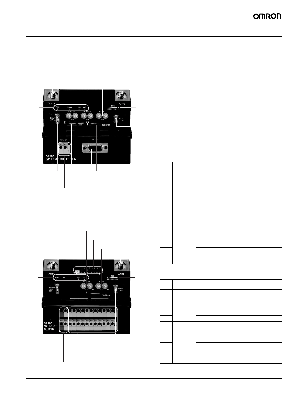
■ Serial Master Station
Unit No. switch
Set the unit number of the Serial Master Station.
Node setting switch (WNODE)
Set the number of connected I/O Slave Stations.
Channel setting switch (WCH)
Antenna terminal (ANT1)
Status
indicators
Mode selection switch
Switch between RUN,
TEST, and SET mode.
Power supply terminal
Supply power to the WT30.
RS-232C Terminal
Connect the PLC, personal computer, etc.
Serial communications
setting switch
Set the baud rate.
Set the communications frequency
channel.
Function setting switch
Make the detailed settings
for RUN/TEST/SET mode.
■ I/O Slave Station
Node setting switch (WNODE)
Set the unit number of the I/O Slave Station.
I/O terminal status indicators (0 to 7 or 8 to 15)
The contact status is displayed.
Antenna terminal (ANT1)
Channel setting switch (WCH)
Set the communications frequency.
Antenna terminal (ANT2)
Received
signal
strength
indicator
Special
function
switch
Antenna terminal (ANT2)
■ Unit No. Switch
Set the unit number of the Serial Master Station
Default: 00
■ Node Setting Switch (WNODE)
Set the number of connected I/O Slave Stations.
Set the node number of the Slave Stations being used as I/O Slave
Stations. The Slave Station functions as a relay station when the
node number is set to 99.
Default: 01
■ Channel Setting Switch (WCH)
Set the communications frequency.
Default: 02
■ Function Setting Switch
Serial Master Station
No. Applicable
mode
1 RUN mode Holds I/O status data
2 Enable scan list Disable scan list
3 Relays used Relays not used
4 TEST mode Signal strength monitor
5 All channels
6 --- ---
7 SET mode Scan list recognition Nothing done
8 Registers specified I/O
9 Recognizes serial
10 Not used --- ---
ON functions OFF functions
Clears I/O status data
when a
communications error
occurs.
when a
communications error
occurs.
Signal strength monitor
disabled
enabled
Specified channels
automatically switched
Registers all I/O slaves
slave
automatically
Ignores serial numbers
numbers
Status
indicators
Mode selection switch
Switch between RUN,
TEST, and SET mode.
Power supply terminal
Supply power to the WT30
and output circuits.
I/O terminals
Connect the contact
signals.
Special function switch
Function setting switch
Make the detailed settings
for RUN/TEST mode.
Received
signal
strength
indicator
I/O Slave Station
No. Applicable
mode
1 RUN mode Holds I/O status data
2 Input hold Normal mode
3 Input filter: 100 ms Input filter: 10 ms
4 TEST mode Signal strength monitor
5 All channels
6 Installation test
7 to 10Not used --- ---
FA Wireless SS Terminals WT30 3
ON functions OFF functions
Clears I/O status data
when a
communications error
occurs.
when a
communications error
occurs.
Signal strength monitor
disabled
enabled
Specified channels
automatically switched
Nothing done
function
Page 4
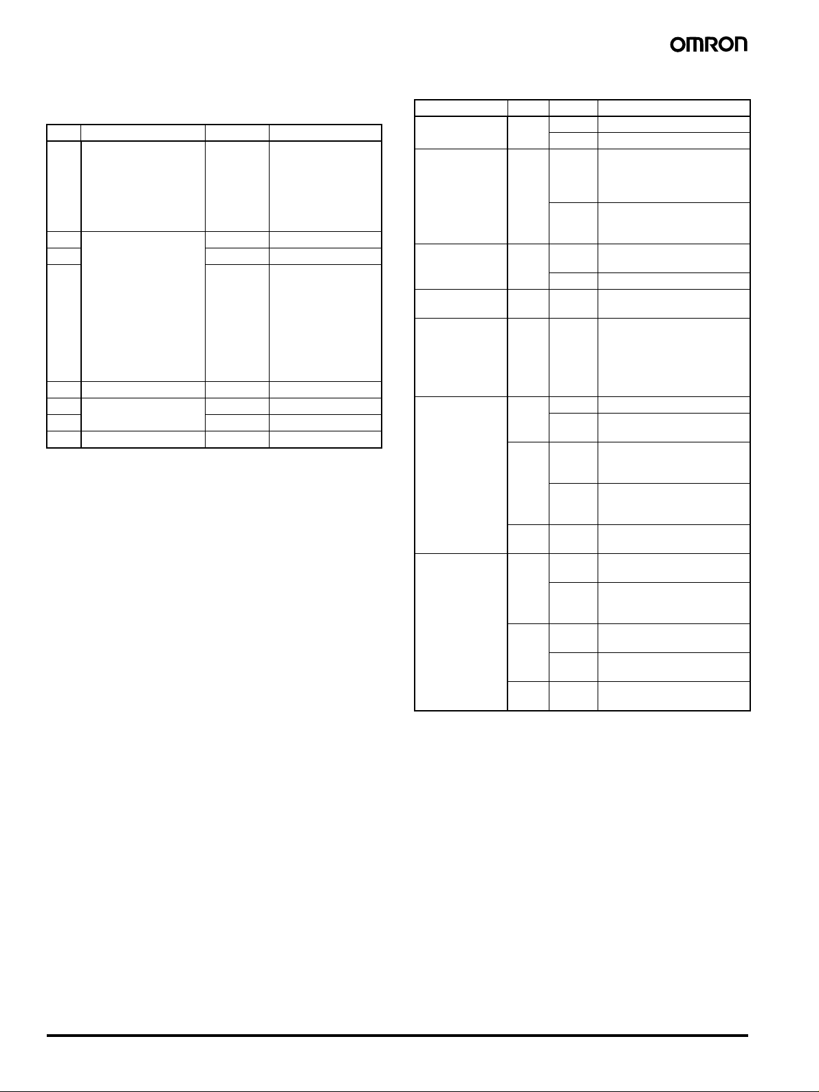
■ Serial Communications Setting
■ Display
Switch
No. Function ON OFF
1 Communications setting
selection
2 Baud rate (bps)
(See note.)
3 20
Total value = 0: 1,200
4 40
5 Data length 8 bits 7 bits
6 Parity None Yes
7 Odd Even
8 Stop bits 1 bit 2 bits
Note: For example, if pins number 2, 3, and 4 are all ON, the total is
7, which corresponds to a baud rate of 115,200 bps.
= 1: 2,400
= 2: 4,800
= 3: 9,600
= 4: 19,200
= 5: 38,400
= 6: 57,600
= 7: 115,200
Detailed
settings
(settings for
No. 2 to 8
used)
10
Default settings
(baud rate: 9,600 bps;
data length: 7 bits;
parity: even; stop bits:
2)
Settings for No. 2 to 8
are ignored.
Indicator Color Status Meaning (primary error)
PWR Green Lit Power is being supplied.
Not lit Power is not being supplied.
ERR
(Slave Station)
COMM
(Master Station)
0 to 15
(Slave Station)
RSSI Red/
MS
(Module Status)
WS
(Wireless
Status)
Red Lit Error output is ON:
Not lit No wireless device error or
Yellow Lit Serial communications in
Not lit No serial communications.
Yellow Lit/Not lit ON/OFF status for input or
Lit/
All not lit
Yellow/
Green
Green Lit Communications are normal.
Flashing TEST mode or SET mode has
Red Lit A fatal error has occurred that
Flashing A non-fatal error has occurred
--- Not lit Power is not being supplied or
Green Lit The station has joined the
Flashing Permission to join wireless
Red Lit A fatal error has occurred that
Flashing Error from which recovery is
--- Not lit Wireless communications are
Wireless device error or
wireless communications
error. (See note)
wireless communications
error.
progress.
output signals
Receiving Signal Strength
Indicator monitor: Number of
indicators lit (receiving signal
strength 1 to 9)
Receiving signal strength less
than 0 to 1.
been activated.
cannot be recovered from.
Replace the Unit
that can be recovered from by
resetting the system.
the system is resetting.
wireless network.
network received from Serial
Master Station (Slave Station)
cannot be recovered from.
possible
not in progress.
4 FA Wireless SS Terminals WT30
Note: When using the WD30 as the Serial Master Station, the ERR
indicator will light if normal I/O communications are not
possible due to an error in the host network.
Page 5
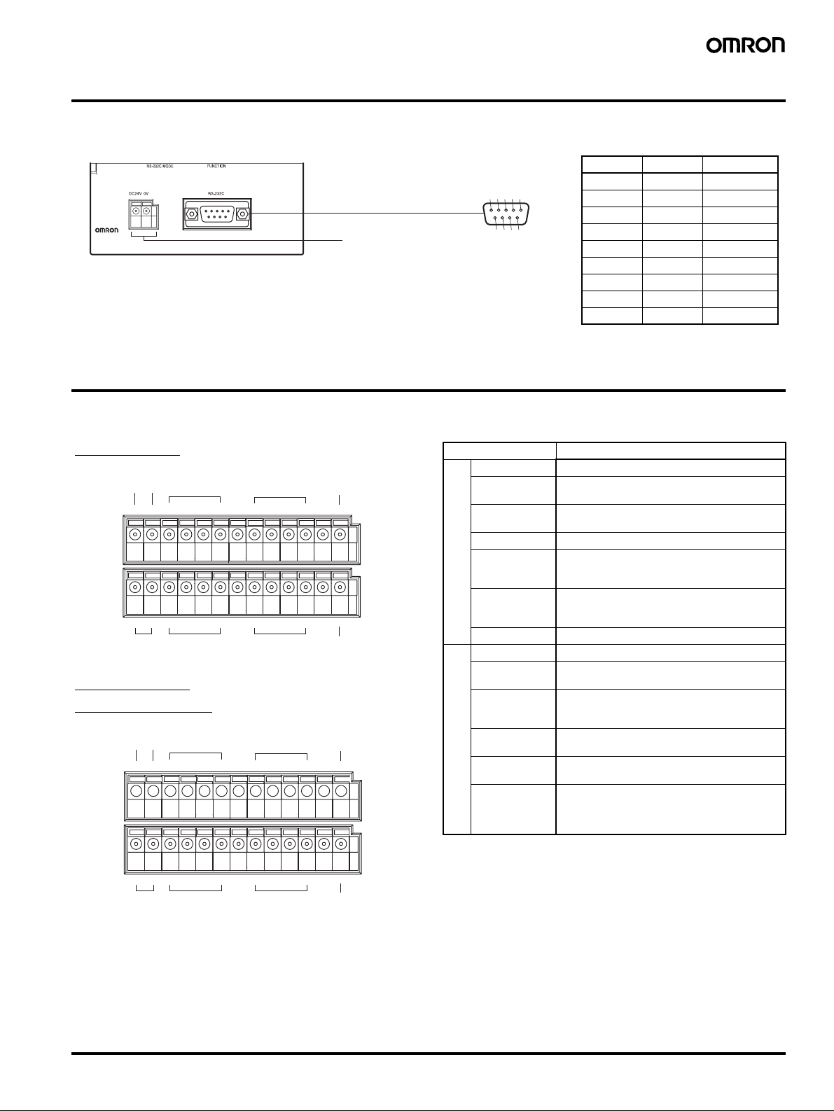
Wiring
(
)
■ Serial Master Station (WT30-M01-FLK)
WT30
Power supply terminal
Supply power to the Unit
I/O Characteristics
■ I/O Slave Station
RS-232C Connector
54321
9876
D-sub, 9-pin, Female End at WT30
Pin No. Signal I/O direction
1 --- ---
2RDOutput
3 SD Input
4 --- ---
5 SG ---
6 --- ---
7 --- ---
8 --- ---
9 --- ---
WT30-SID16
Error output
power supply
VG 01 2 3
24 V DC
Power supply Inputs Inputs
Inputs Inputs
0 V 8 9 10 11
WT30-SMD16
WT30-SMD-16-1
Error output/output
power supply
VG0 1 2 3
Inputs Inputs
IN
COM
4567
COM
12 13 14 15
IN
COMIN4567
Error output
(PNP)
COM ERRP
ERRN
COM
Error output
NPN
Error output
(PNP)
COM ERRP
Item Specifications
Input voltage 24 V DC
Allowable
20.4 to 26.4 V DC
voltage range
Input
impedance
4.7 k
Ω (typical)
Input current 5 mA (typical)
ON voltage/
17.4 V DC, 3.0 mA min.
current
characteristics
OFF voltage/
Input Characteristics
current
5.0 V DC, 1.0 mA max.
characteristics
Input filter 10 ms/100 ms (Selected using switch.)
Input voltage 24 V DC
Allowable
20.4 to 26.4 V DC
voltage
Max.
switching
current
Leakage
100 mA max. per output (at 20.4 to 26.4 V DC)
Simultaneous usage of error output NPN/PNP
is not possible.
0.1 mA max.
current
Residual
voltage
Characteristics
Output/Error Output
Fuse One for every two outputs except for error
1.0 V max.
output circuits, which have one for every NPN/
PNP output. (No fuses can be replaced by the
user.)
24 V DC
0 V 0 1 2 3
Power supply Outputs Outputs
COM
4567
OUT
COM ERRN
Error output
(NPN)
FA Wireless SS Terminals WT30 5
Page 6
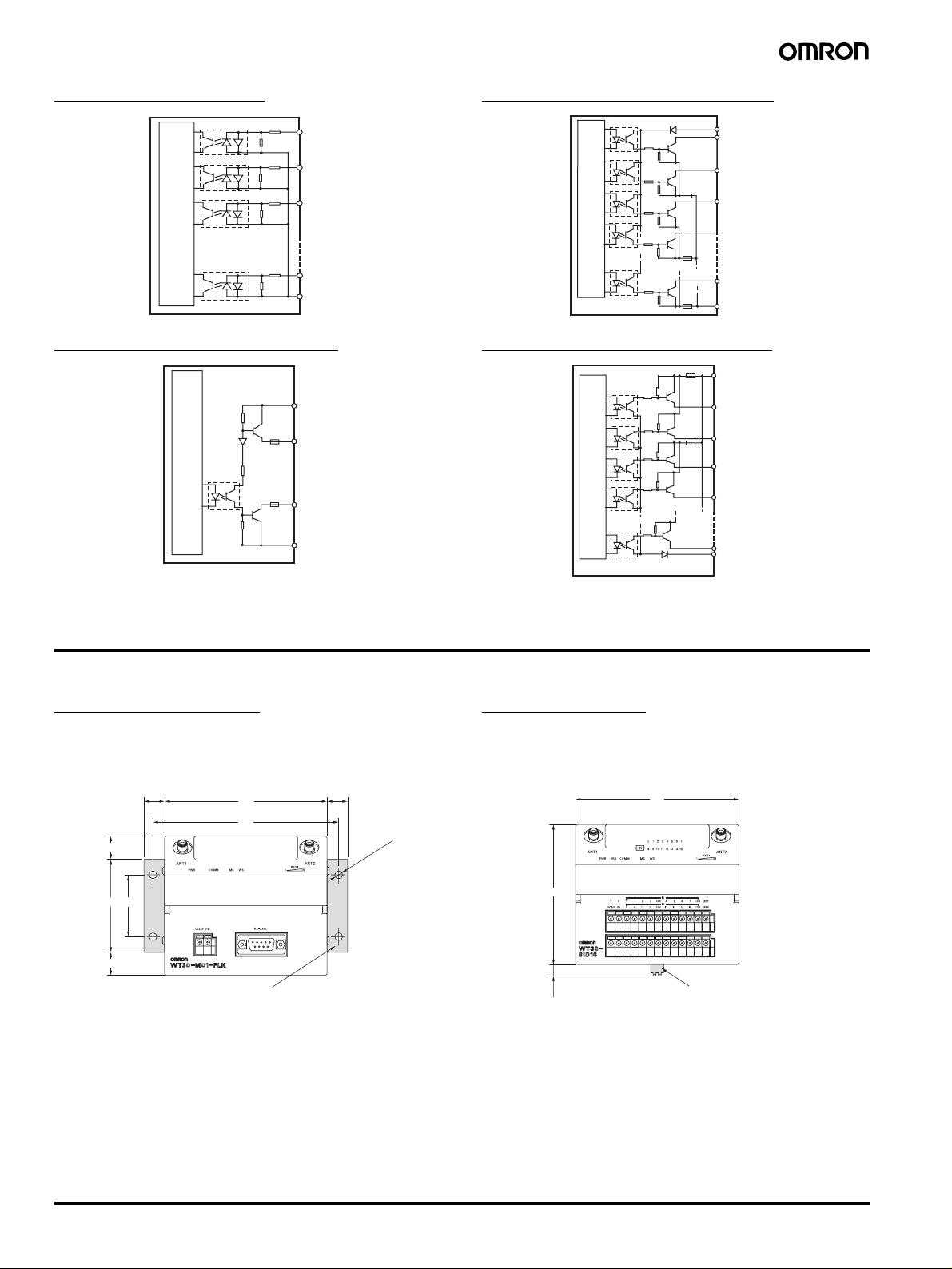
Input Circuit Diagram
3
Output Circuit Diagram (NPN)
IN 0
IN 1
IN 2
Secondary internal circuit
IN 15
COM (IN)
Error Output Circuit Diagram
V
Fuse
ERRP
Fuse
ERRN
Secondary internal circuit
G
V
OUT 0
OUT 1
Fuse
OUT 2
Secondary internal circuit
Fuse
Fuse
OUT 7
G
Output Circuit Diagram (PNP)
Fuse
V
OUT 0
OUT 1
Fuse
OUT 2
OUT
Secondary internal circuit
OUT 7
G
Dimensions
Note: All units are in millimeters unless otherwise indicated.
Serial Master Station
WT30-M01-FLK
13.3
(15)
60 40
(15)
105 13.3
120
Surface mounting bracket
WT30-FT003
Four, 5 dia.
I/O Slave Station
WT30-SID16
WT30-SMD16
WT30-SMD16-1
90
7.3
105
DIN rail mounting bracket
WT30-FT001 or WT30-FT002
6 FA Wireless SS Terminals WT30
Page 7
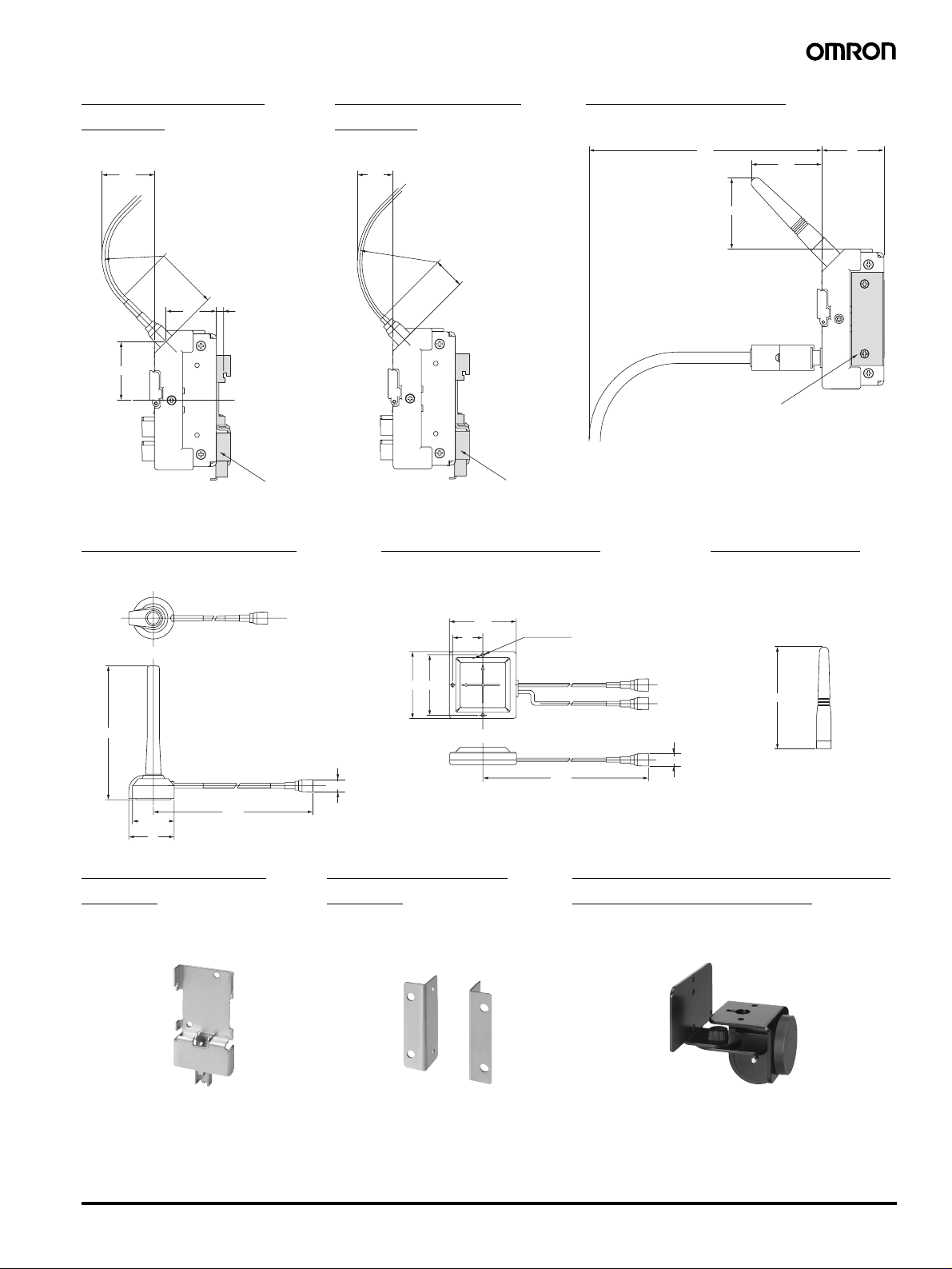
With Magnet-base
t
.
Antenna
WT30-AT001
(34)
With Flat Diversity
Antenna
WT30-AT002
(23)
With Pencil Antenna
WT30-AT003
150
(46)
(46)
40
R38
R40
(32)
(38)
I/O Slave Station
4.6
DIN Rail mounting bracket
WT30-FT001 or
WT30-FT002
Magnet-base Antenna
WT30-AT001
R50
20
I/O Slave Station
DIN Rail mounting bracke
WT30-FT001 or
WT30-FT002
Flat Diversity Antenna
WT30-AT002
57.5
57.5
26
52
Three, 3 dia.
Surface Mounting Bracket
WT30-FT003
Serial Master Station
Pencil Antenna
WT30-AT003
75
115
35.8 dia.
39
2010
DIN Rail Mounting
Bracket
WT30-FT001
WT30-FT002
10.5 dia.
Surface Mounting
Bracket
WT30-FT003
10.5 dia
2010
Flat Diversity Antenna Mounting
Brackets (with magnets)
WT30-FT011
FA Wireless SS Terminals WT30 7
Page 8

ALL DIMENSIONS SHOWN ARE IN MILLIMETERS.
To convert millimeters into inches, multiply by 0.03937. To convert grams into ounces, multiply by 0.03527.
Cat. No. N139-E1-01
In the interest of product improvement, specifications are subject to change without notice.
OMRON Corporation
Industrial Automation Company
Industrial Devices and Components Division H.Q.
Wireless Components Department
Shiokoji Horikawa, Shimogyo-ku,
Kyoto, 600-8530 Japan
Tel: (81)75-344-7116/Fax: (81)75-344-7189
Printed in Japan
0105
 Loading...