

Omron WE70-AP, WE70-CL Operation Manual

OPERATION MANUAL
WE70-AP/CL
FA Wireless LAN Unit
Cat. No. N153-E1-01


1
This manual describes a wireless unit set conformance to
IEEE802.11a and IEEE802.11b/g* wireless LAN.
Please read this manual carefully and be sure you understand the
information provided before attempting to operate this product.
* IEEE802.11g is compatible with IEEE802.11b.
The Radio Law prohibits outdoor use of wireless LAN in
IEEE802.11a standard (5GHz band).
About this Manual

2
Caution for the Radio Law on Wireless LAN
● The Radio Law prohibits outdoor use of wireless LAN in IEEE802.11a standard (5GHz band).
● Do not use it close to a person with a cardiac pacemaker.
Electromagnetic interference may affect it, putting his/her life at risk.
● Do not use it close to medical equipment.
Electromagnetic interference may affect the cardiac pacemaker to cause loss of human life.
● Do not use it close to an electric oven.
Electromagnetic interference may affect the medical equipment to cause loss of human life.
● Radio device in this product has been certified by the Radio Law. Do not disassemble or modify this
product.
Caution for Radio Interference with 2.4GHz Wireless LAN
Take the following precautions for communication by 2.4GHz (IEEE802.11b/g) wireless LAN.
Within this product's frequency range, industrial, scientific, and medical equipment, such as electric oven, as
well as RFID premises radio stations (license required) and specified low power radio station and ham radio
station (license not required) used in factory manufacturing lines are operated.
❍ Before using this device, confirm that no RFID premises radio station, specified low power radio station,
or ham radio station is operating close to it.
❍ If this product caused radio interference with an RFID premises radio station, immediately change the
product's frequency or stop radio emission, and contact OMRON representative for actions to take to
prevent cross talk.
Wireless LAN Standards Supported by This Product
This product supports the following wireless LAN standards:
• IEEE802.11a :Up to 54Mbps (5GHz band)
• IEEE802.11g :Up to 54Mbps (2.4GHz band)
• IEEE802.11b :Up to 11Mbps (2.4GHz band)
* IEEE802.11g is compatible with IEEE802.11b.

3
Overview of This Product
• Accessory antenna of this product uses an external diversity type supporting 5GHz and 2.4GHz bands.
• This product provides DFS function that can automatically avoid radio interference by weather radar or
others while using IEEE802.11a.
* For more information on the DFS function, see "3-3 Configuring IP Address/SSID/Channel", "DFS
Function" (P.3-11).
• In addition to WEP RC4 and OCB AES encryption, TKIP, AES, and WOC KEY are supported.
• AP-to-AP bridging allows wireless connection between APs (access points).
• Spanning tree function can prevent problems related to network groups.
• This product supports 10BASE-T and 100BASE-TX wired LAN types are supported (automatic switching).
• Major setup of this product can be performed through a WWW browser.
• This product received Technical Standard Conformity Certification and does not require radio station
license.
• AP-to-AP bridging is not available at the channel where DFS function is provided.

Notations
This document uses the following notation conventions:
" " :A name of a window of the operating system (OS), a setup screen menu item, or a setup screen under
a menu item is represented by " ".
[ ] :A name of a tab, icon, text box, check box, or setup item in a setup screen is represented by [ ].
< > : A name of a command button in a dialog box is represented by < >.
*Microsoft
®
Windows®Vista is indicated as Windows Vista.
Microsoft
®
Windows®XP Professional and Microsoft®Windows®XP Home Edition are indicated as
Windows XP.
Microsoft
®
Windows®2000 Professional is indicated as Windows 2000.
* Setup screen shown in this document may be different from those of your PC depending on your OS
version and preferences.
4

5
Warranty and Limitations of Liability
1. WARRANTY
WARRANTY
OMRON's exclusive warranty is that the products are free from defects in Documents and workmanship
for a period of one year (or other period if specified) from date of sale by OMRON.
OMRON MAKES NO WARRANTY OR REPRESENTATION, EXPRESS OR IMPLIED, REGARDING
NON-INFRINGEMENT, MERCHANTABILITY, OR FITNESS FOR PARTICULAR PURPOSE OF THE
PRODUCTS. ANY BUYER OR USER ACKNOWLEDGES THAT THE BUYER OR USER ALONE HAS
DETERMINED THAT THE PRODUCTS WILL SUITABLY MEET THE REQUIREMENTS OF THEIR
INTENDED USE. OMRON DISCLAIMS ALL OTHER WARRANTIES, EXPRESS OR IMPLIED.
2. LIMITATIONS OF LIABILITY
LIMITATIONS OF LIABILITY
OMRON SHALL NOT BE RESPONSIBLE FOR SPECIAL, INDIRECT, OR CONSEQUENTIAL
DAMAGES, LOSS OF PROFITS OR COMMERCIAL LOSS IN ANY WAY CONNECTED WITH THE
PRODUCTS, WHETHER SUCH CLAIM IS BASED ON CONTRACT, WARRANTY, NEGLIGENCE, OR
STRICT LIABILITY.
In no event shall responsibility of OMRON for any act exceed the individual price of the product on which
liability is asserted.
IN NO EVENT SHALL OMRON BE RESPONSIBLE FOR WARRANTY, REPAIR, OR OTHER CLAIMS
REGARDING THE PRODUCTS UNLESS OMRON'S ANALYSIS COMFIRMS THAT THE PRODUCTS
WERE PROPERLY HANDLED, STORED, INSTALLED, AND MAINTAINED AND NOT SUBJECT TO
CONTAMINATION , ABUSE, MISUSE, OR INAPPROPRIATE MODIFICATION OR REPAIR.
3. Application Considerations
SUITABILITY FOR USE
OMRON shall not be responsible for conformity with any standards, codes, or regulations that apply to the
combination of products in the customer's application or use of the product.
At the customer's request, OMRON will provide applicable third party certification documents identifying
ratings and limitations of use that apply to the products. This information by itself is not sufficient for a
complete determination of the suitability of the products in combination with the end product, machine,
system, or other application or use.
The following are some examples of applications for which particular attention must be given. This is not
intended to be an exhaustive list of all possible uses of the products, nor is it intended to imply that the
uses listed may be suitable for the products:
• Outdoor use, uses involving potential chemical contamination or electrical interference, or conditions or
uses not described in this document.

6
Do not use IEEE802.11 outdoors.
The Radio Law in Japan prohibits outdoor use of IEEE802.11a (5.2GHz/5.3GHz band).
Within this product's frequency range, industrial, scientific, and medical equipment as well as
RFID premises radio station (license required) and specified low power radio station (license
not required) used in factory manufacturing lines are operated.
(1) Before using this device, confirm that no RFID premises radio station or specified low power
radio station is operating close to it.
(2) If in case this product causes radio interference with an RFID premises radio station,
immediately change the product's frequency or stop radio emission, and contact OMRON
representative for actions to take to prevent cross talk (e.g. installation of a partition)
(3) If any other problem occurred due to this product, such as radio interference with an RFID
specified low power radio station, contact OMRON representative.
• Nuclear energy control systems, combustion systems, railroad systems, aviation systems, medical
equipment, amusement machines, vehicles, safety equipment and installations subject to separate
industry or government regulations.
• Systems, machines, and equipment that could present a risk to life or property.
Please know and observe all prohibitions of use applicable to the products.
NEVER USE THE PRODUCTS FOR AN APPLICATION INVOLVING SERIOUS RISK TO LIFE OR
PROPERTY WITHOUT ENSURING THAT THE SYSTEM AS A WHOLE HAS BEEN DESIGNED TO
ADDRESS THE RISKS, AND THAT THE OMRON PRODUCT IS PROPERLY RATED AND INSTALLED
FOR THE INTENDED USE WITHIN THE OVERALL EQUIPMENT OR SYSTEM.
4. Disclaimers
CHANGE IN SPECIFICATIONS
Product specifications and accessories may be changed at any time based on improvements and other
reasons.
It is our practice to change model numbers when published ratings or features are changed, or when
significant construction changes are made. However, some specifications of the product may be changed
without any notice. When in doubt, special model numbers may be assigned to fix or establish key
specifications for your application on your request. Please consult with your OMRON representative at
any time to confirm actual specifications of purchased product.
Approved Standards
Conforming Wireless Standards:
Japan: ARIB STD-T66,T71
USA: FCC part 15.247,401-407
Chinese domestic wireless standard [2002]353,[2002]227
Europe: EN 300 328,EN 301 893
Conforming Safety Standards:
cUL 60950-1(Listing)
EN 60950-1
Conforming EMC Standards: EN 301 489-3,EN 301 489-17
Conforming EMF Standards: EN 50371

7
FCC WARNING
Changes or modifications not expressly approved by the party responsible for compliance could void the
user's authority to operate the equipment.
NOTICE
This equipment has been tested and found to comply with the limits for a Class B digital device, pur-
suant to part 15 of the FCC Rules. These limits are designed to provide
reasonable protection against harmful interference in a residential installation.
This equipment generates, uses and can radiate radio frequency energy and, if not installed and used in
accordance with the instructions, may cause harmful interference to radio communications. However,
there is no guarantee that interference will not occur in a particular installation. If this equipment does
cause harmful interference to radio or television reception, which can be determined by turning the
equipment off and on, the user is encouraged to try to correct the interference by one or more of the fol-
lowing measures:
• Reorient or relocate the receiving antenna
• Increase the separation between the equipment and receiver.
• Connect the equipment into an outlet on a circuit different from that to which the receiver is connected.
• Consult the dealer or an experienced radio/TV technician for help.
STP cables must be used for connection to host computer and/or peripherals in order to meet FCC
emission limits.
In according with 47 CFR Part15.407(e) U-Nll devices operating in 5.15-5.25GHz frequency bands are
restricted to indoor operations only.
This transmitter must not be co-located or operated in conjunction with any other antenna or transmitter.
This equipment complies with FCC radiation exposure limits set forth for uncontrolledequipment and
meets the FCC radio frequency (RF) Exposure Guidelines in Supplement C to OET65. This equipment
should be installed and operated with at least 20cm and more between the radiator and person's body
(excluding extremities: hands, wrists, feet and legs).
We, the manufacturer (name of the manufacturer) hereby declare that this equipment (type of the equip-
ment), model WE70-AP-EU/WE70-CL-EU is in compliance with the essential requirements and other
relevant provisions of Directive 1999/5/EC.
Applicable Countries
This product has been approved for wireless standards in the countries listed
below. This product cannot be used in any other countries.
WE70-AP/CL-US(United States), WE70-AP/CL-EU(Austria, Denmark, Finland, Germany, United Kingdom,
Ireland, Italy, Netherlands, Norway, Sweden, Switzerland, Spain, France, Belgium, Greece, Portugal, Czech,
Hungary, Poland, Slovenia, Slovakia), WE70-AP/CL-CN(China), WE70-AP/CL(Japan)
Conformance to EN Standards
Use a DC power line less than 3 m to conform to EN standards. If a power line
of 3 m or longer is required, extend the length at the Switching Power Supply's
primary side (i.e., the AC power line).
Conformance to UL Standards
Always use a Listing Class 2 power supply to conform to UL standards.
Using 5.8GHz in China
Gain approval from the wireless management body of a local province, autonomous region or city under the
direct jurisdiction for installing and using frequency of 5.8GHz in China.
Related body: Ministry of Information Industry (http://www.mii.gov.cn/)
Safety Precautions
8
■ Indication for Safe Use
This document uses the following indication and symbols in precautions for safe use of WE70-AP/CL.
Precautions here specifies very important things related to safety and must be complied.
Indication and symbols include:
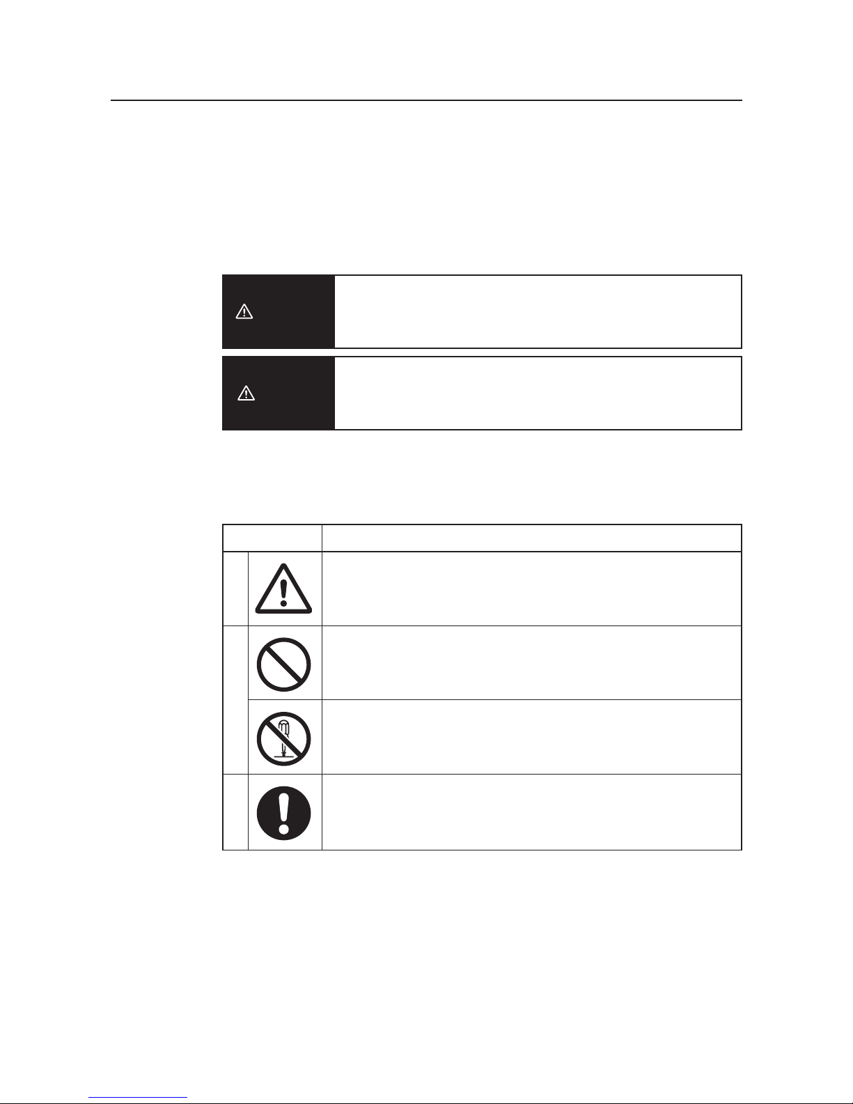
Warning Indication
Indicates a potentially hazardous situation which, if not avoided, will
result in minor or moderate injury, or may result in serious injury or
death. Additionally there may be significant property damage.
Indicates a potentially hazardous situation which, if not avoided,
may result in minor or moderate injury or in property damage.
■ Meanings of Alert Symbols
Caution
Warning
MeaningSymbol
Precautions
• General precaution
Indicates unspecified general precaution, warning, and hazard.
• General prohibition
Indicates unspecified general prohibition.
• Do Not Disassemble
Indicates that disassembly of equipment may cause an electrical
shock or injuries.
• General mandatory indication
Indicates unspecified general mandatory operation.
ProhibitionMandatory
9
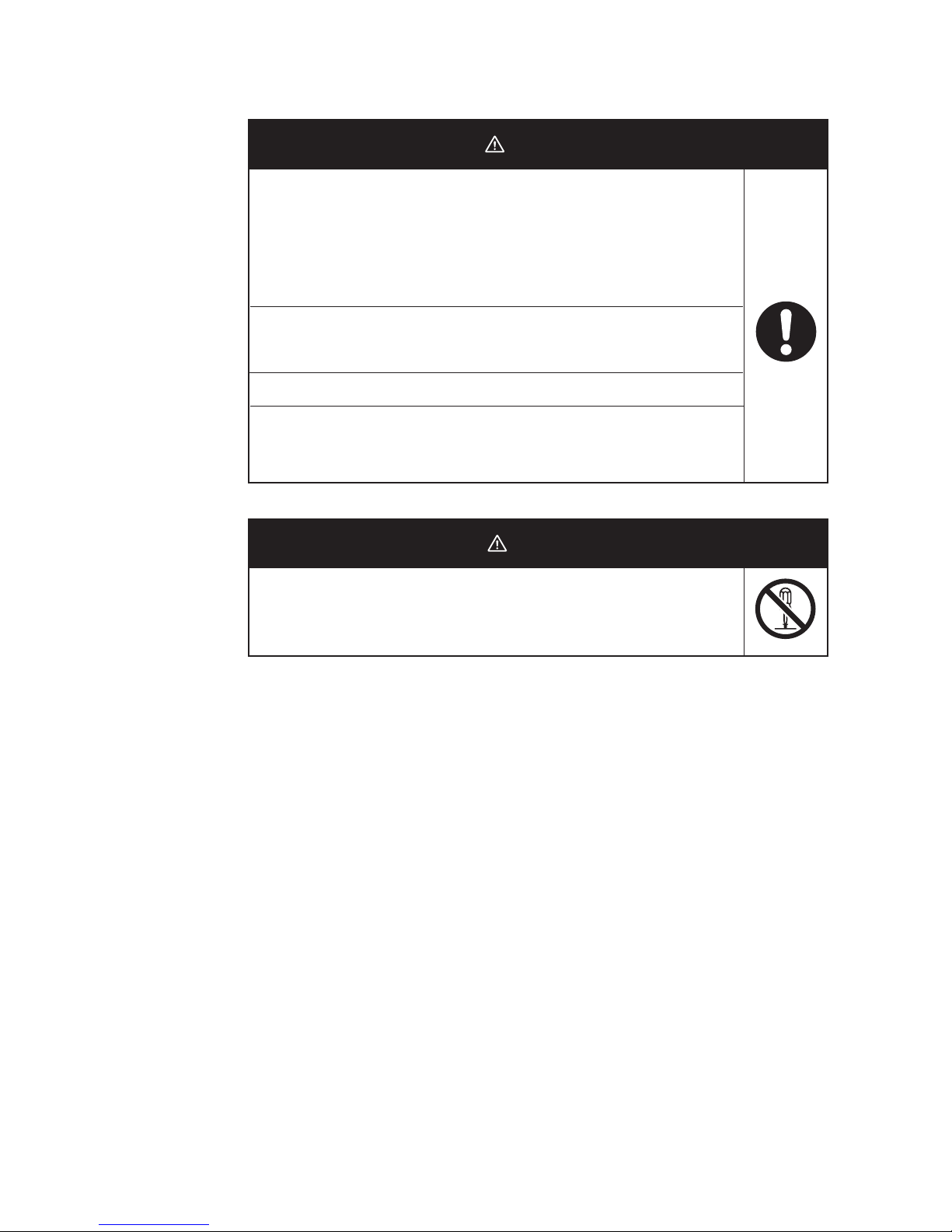
■ Warning Indication
DO NOT use this product without a protection circuit. Otherwise it may
result in heavy injuries or damage on property due to malfunction.
Dual or triple safety protection circuits, such as emergency stop, interlock,
or limit circuit, must be configured by external control circuit so that the
system should operate on safe side even if a failure of this product or an
error due to an external factor occurred.
This product uses electric wave for communication which may be broken
up temporarily due to its environment or usage.Safety of the system must
be maintained even in such a case.
Do not use this product for a real-time control application.
DO NOT use this product close to any medical equipment such as a
cardiac pacemaker as it may affect operation of such medical equipment
and may result in heavy injuries.
Warning
In rare cases, light electric shock, fire, or failure of this product may
occur.Do not disassemble, modify, fix, or touch inside of this product.
Disassembly and modification are prohibited by the Radio Law in each
country.
Caution

10
Precautions for Safe Use
Observe the following precautions when using this product.
1) Dedicated packaging must be used for transportation of this product. Take precautions to prevent
excessive vibration or shock on the product or falling of the product.
2) Storage of this product must be within the specified environment. Allow the product to warm up to room
temperature for at least 3 hours after it has been stored at -10 degrees C or lower.
3) Use the product within the specified temperature and humidity ranges.
4) Do not use the product under the following environments:
• Locations subject to extreme temperature changes resulting in condensation
• Locations subject to static electricity, excessive noise, or electric fields
• Locations where the product may come into contact with water, oil, or chemicals
• Locations where corrosive gases or flammable gases are present
• Locations where large amounts of dust or dirt are present
• Locations subject to spatters, iron chips, or fillings
5) Do not use it outdoors (outside a control panel).
6) Use tape, cord, or other means to hold the product while adjusting the installation position to prevent the
product from damage due to failing.
7) Tighten the mounting screws to the specified torque of 4.4 to 5.3 in lb. (0.5 to 0.6 N
m)
8) Provide sufficient space around the product for heat dissipation. Install the products with a margin of
20mm or longer externally.
9) Do not reverse the power supply connection or connect the product to an AC power supply.
10) Use the correct power supply voltage.
11) Use the solid wire, 16 to 12 AWG for power supply. The exposed length of wire is 10 to 11mm(UL
Listing).
12) Do not lay communications cables and antenna cables near other high-voltage cables or power lines.
13) Setup is required after the installation or replacement of this product. Set up the product correctly
according to the manual, and be sure to confirm that communication is established before using it.
14) Do not apply excess vibrations or shock to this product. Do not drop this product.
15) Other wireless devices operating within the same frequency band may interfere with this product or be
adversely affected by this product. Therefore, be sure to perform the test provided with the product (e.g.,
installation tests) before operating it.
16) Make sure that the antenna is not disconnected during operation.
17) Do not use this product near other devices that may malfunction due to the electromagnetic waves
emitted by this product.
18) Turn OFF the power supply before performing any wiring or replacing devices.
19) Do not touch the product with wet hands.
20) Dispose of the product as industrial waste.
Contents
11
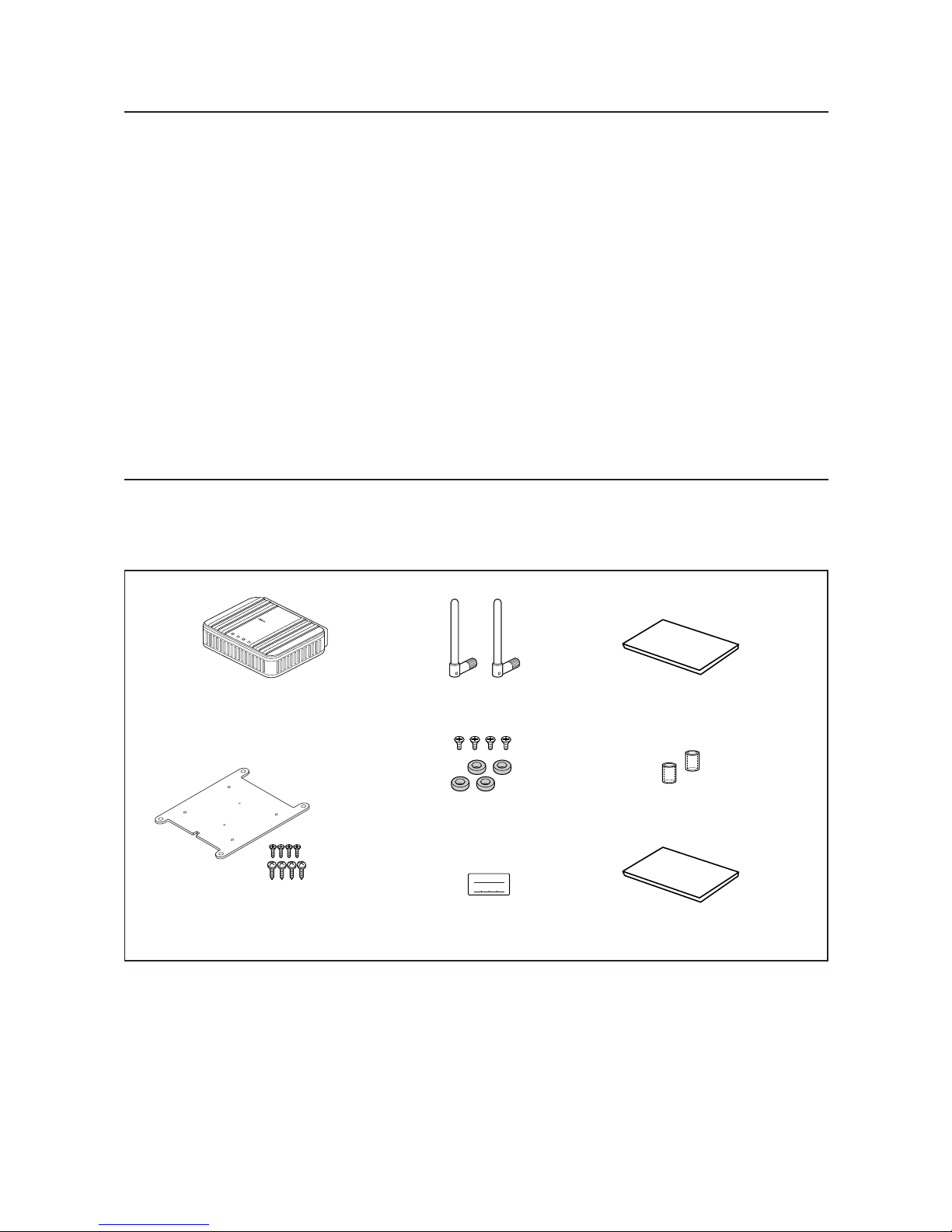
This product package includes the followings. (WE70-AP/CL-US/-EU/-CN)
Check if all of them are included in the package before using this product.
IP ADDRES
SUBNET MASK
Instruction Sheet x 3
EC Declaration of Conformity
Antenna Connector
Cover x 2
IP Address Label
Antenna x 2
Magnet x 4
(with 4 flat-head screws)
LAN
MODE
POWER
WIRELESS
WE70-AP
F
A
W
I
R
E
L
E
S
S
L
A
N
A
C
C
E
S
S
P
O
I
N
T
WE70-AP/WE70-CL
Mounting Bracket
(with 4 flat-head screws)
(with 4 tapping screws)
Precautions for Correct Use
Always heed these precautions to prevent faulty operation, malfunction, or adverse affect on the product's
performance and functionality.
1) Communication performance may be affected by its environment. Always confirm its operation before
using it.
2) Do not install its antenna where it is surrounded by metal, such as in a control panel.
3) Install the antenna so that it is as far away as possible from and not parallel to electric wires or metal
plates.
4) Do not use this product in areas exposed to extremely high humidity, near televisions or radios, near
motors or drills that emit sparks, near strong magnets, or near fluorescent lights.
5) Do not pull or bend cables with force.
12
(As of December 2006)
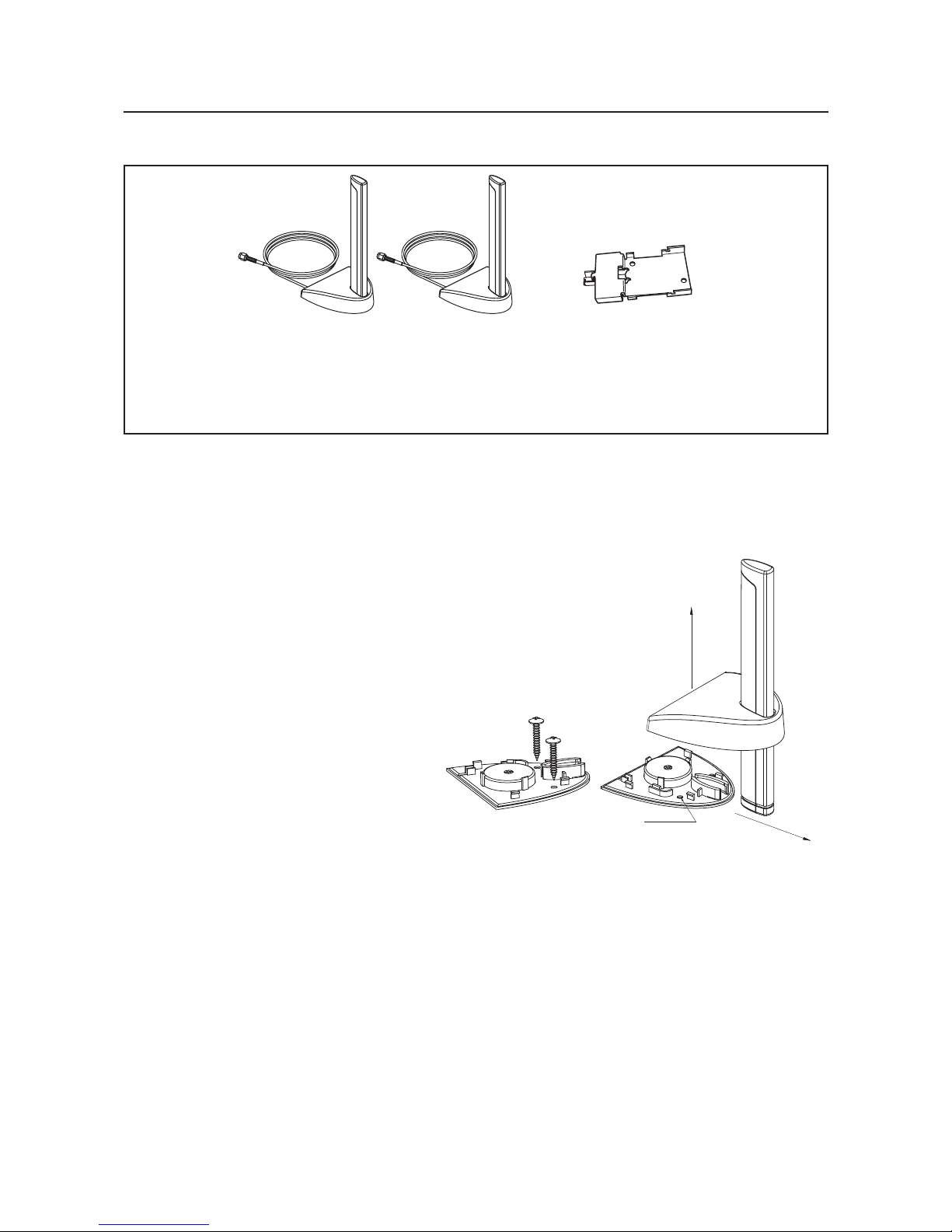
<Magnetic-base Antenna>
WE70-AT001H is a non-directional antenna for 2.4/5GHz.
It can be installed where radio wave status is good, within a range of a given coaxial cable length (about 2m).
1 set with 2 antennas
Magnetic-base Antenna
Common for 2.4GHz and
5GHz bands
(WE70-AT001H)
DIN Rail Adapter
(WT30-FT001, 002)
Options
Assembly direction
Screw hole
Assembly direction
Assembly drawing
Application Guide
13
Basic Function
See
P.3-1
Refer to "Chapter 3. Basic Setup".
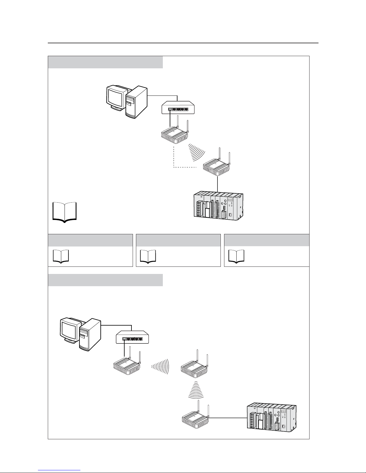
Constructs a network through radio communication.
AP-to-AP Bridging (Relay function)
An access point is used as a repeater for communication with a client (slave).
Under this system configuration, a client (CL-1) as a fixed station communicates with an access point (AP-2).
LAN
MODE
POWER
W
IREL
ES
S
W
E
7
0
C
L
F
A
W
I
R
E
L
E
S
S
L
A
N
A
C
C
E
S
S
P
O
I
N
T
Client (Slave)
WE70-CL
L
A
N
M
O
D
E
P
O
W
E
R
W
IR
E
L
E
S
S
W
E
7
0
-A
P
F
A
W
I
R
E
L
E
S
S
L
A
N
A
C
C
E
S
S
P
O
I
N
T
Access Point
WE70-AP
Access Point
WE70-AP
L
A
N
M
O
D
E
P
O
W
E
R
W
IR
E
L
E
S
S
W
E
7
0
-A
P
F
A
W
I
R
E
L
E
S
S
L
A
N
A
C
C
E
S
S
P
O
I
N
T
AP-to-AP
Bridging
Ethernet
HUB
Ethernet
PC
Pattern A
CL-1
CL-1
AP-2AP-2
AP-1AP-1
See
P. 3 - 12
Enhancing Security
Refer to "Chapter 3-4.
Configuring Encryption".
See
P. 6 - 2
Replacing Wireless Unit
Refer to "Chapter 6-1.
Replacing Wireless Unit".
See
P. 2 - 1
Installation
Refer to "Chapter 2.
Installation & Connection".
L
A
N
M
O
D
E
P
O
W
E
R
W
IR
E
L
E
S
S
W
E
7
0
A
P
F
A
W
I
R
E
L
E
S
S
L
A
N
A
C
C
E
S
S
P
O
I
N
T
LAN
MO
DE
PO
W
ER
W
I
RELE
S
S
W
E
7
0
C
L
F
A
W
I
R
E
L
E
S
S
L
A
N
A
C
C
E
S
S
P
O
I
N
T
Access Point
WE70-AP
Client (Slave)
WE70-CL
PLC
Ethernet
HUB
Ethernet
PC
14
See
P.4-2
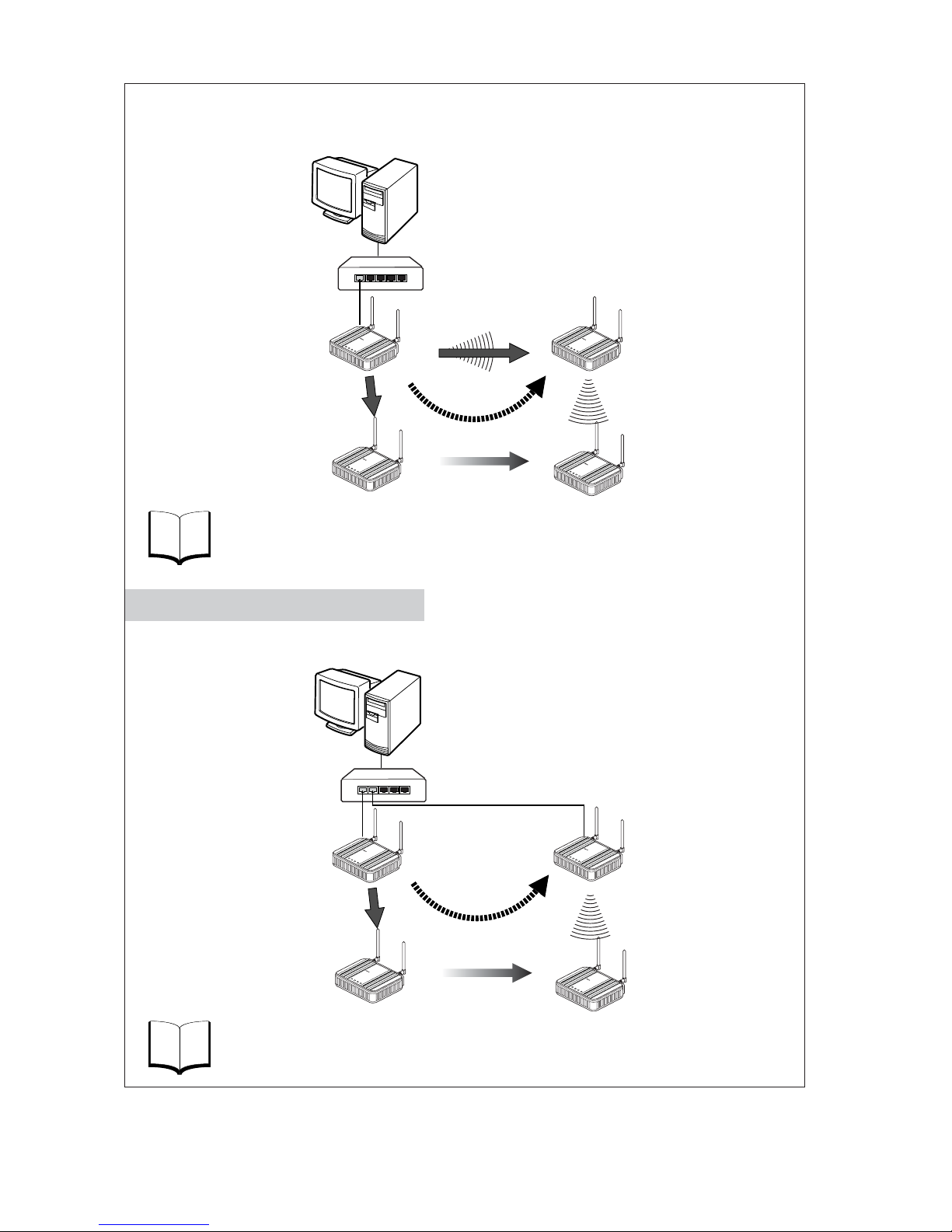
An access point is used as a repeater for communication with a moving client (slave).
A client (CL-1) moves between AP-1 and AP-2, switching communication paths.
Refer to "Chapter 4-1. To Use AP-to-AP Bridging".
See
P.4-22
Refer to "Chapter 4-9. Smart Roaming".
AP-1 and AP-2 are wired through HUB to communicate with a moving client (slave).
A client (CL-1) moves between AP-1 and AP-2, switching communication paths.
Access Point
WE70-AP
Access Point
WE70-AP
AP-to-AP
Bridging
L
A
N
M
O
D
E
P
O
W
E
R
W
I
R
E
L
E
S
S
W
E
7
0
A
P
F
A
W
I
R
E
L
E
S
S
L
A
N
A
C
C
E
S
S
P
O
I
N
T
L
A
N
M
O
D
E
PO
W
E
R
W
IR
E
L
E
S
S
W
E
7
0
A
P
F
A
W
I
R
E
L
E
S
S
L
A
N
A
C
C
E
S
S
P
O
I
N
T
LAN
M
O
DE
POW
E
R
W
I
RE
LE
S
S
W
E
7
0
C
L
F
A
W
I
R
E
L
E
S
S
L
A
N
A
C
C
E
S
S
P
O
I
N
T
L
AN
MO
DE
P
OWE
R
W
IRELES
S
W
E
7
0
C
L
F
A
W
IR
E
L
E
S
S
L
A
N
A
C
C
E
S
S
P
O
I
N
T
Client (Slave)
WE70-CL
Moving
(2) Path is switched
(2) Path is switched
(1) When communication
become unavailable
(3) Communication is
established through
a repeater
Access Point
WE70-AP
Access Point
WE70-AP
L
A
N
M
O
D
E
P
O
W
E
R
W
IR
E
L
E
S
S
W
E
7
0
A
P
F
A
W
I
R
E
L
E
S
S
L
A
N
A
C
C
E
S
S
P
O
I
N
T
L
A
N
M
O
D
E
PO
W
E
R
W
IR
E
L
E
S
S
W
E
7
0
-A
P
F
A
W
I
R
E
L
E
S
S
L
A
N
A
C
C
E
S
S
P
O
I
N
T
LAN
M
ODE
P
OW
ER
W
IRE
LES
S
W
E
7
0
-
C
L
F
A
W
I
R
E
L
E
S
S
L
A
N
A
C
C
E
S
S
P
O
I
N
T
LAN
MODE
POWER
WIRELESS
W
E
7
0
C
L
F
A
W
I
R
E
L
E
S
S
L
A
N
A
C
C
E
S
S
P
O
I
N
T
Client (Slave)
WE70-CL
Moving
(1) When communication
become unavailable
(3) Communication is
established with AP-2
HUB
Ethernet
HUB
Ethernet
Pattern B
Roaming for Wired Connection
PC
CL-1
CL-1
CL-1
CL-1
AP-2AP-2
AP-1AP-1
PC
CL-1
CL-1
CL-1
CL-1
AP-2AP-2
AP-1AP-1

Manual Configuration
15
Chapter 1 Overview
Describes main features of this product.
1
Chapter 2
Installation &
Connection
Describes cautions for wireless unit installation and how to
connect the unit set.
2
Chapter 3 Basic Setup
Describes how to establish communication between an
access point and a client (slave) as well as a PLC using PC.
3
Chapter 4 Advanced Setup
Describes setup for communication between access points
and communication between clients through an access
point,as well as setup for stable communication.
4
Chapter 5 Setup Menu
Describes setup screens available for functions of this
wireless unit set.
5
Chapter 6
Replacement
Procedure
Describes how to save or initialize setup data for wireless
unit replacement.Read this chapter when necessary.
6
Appendices
Describes major troubleshooting, setup screen configuration,
and initial setup values.

Table of Contents
16
About this manual ..................................................1
Warranty and Limitations of Liability ......................5
Safety Precautions.................................................8
Precautions for safe use ......................................10
Precautions for Correct Use.................................11
Contents...............................................................11
Options.................................................................12
Application Guide.................................................13
Manual Configuration...........................................15
Chapter 1 Overview
1-1. Features.............................................................................................................1-2
■ Major Features ..............................................................................................1-2
■ System Configuration ....................................................................................1-7
■ Relay Function ..............................................................................................1-9
1-2. Components and Functions .............................................................................1-10
■ Top View .....................................................................................................1-10
■ Rear View....................................................................................................1-11
Chapter 2 Installation & Connection
2-1. Installation..........................................................................................................2-2
■ Installation Location ......................................................................................2-2
■ Installation Precautions .................................................................................2-2
■ Precautions for Antenna Installation Location...............................................2-3
■ Dimensions ...................................................................................................2-5
■ Installation Method ........................................................................................2-5
2-2. Connection.........................................................................................................2-7
■ Notice for Wiring............................................................................................2-7
■ Main Unit Power Wiring.................................................................................2-7
■ LAN Cabling ..................................................................................................2-8
2-3. Connection Check ...........................................................................................2-10
■ Checking Setup Screen Access..................................................................2-10
Chapter 3 Basic Setup
3-1. Setup Workflow..................................................................................................3-2
3-2. Opening Setup Screen ......................................................................................3-3
Step 1. PC (Wired LAN) Setup ..........................................................................3-3
Step 2. Connecting ............................................................................................3-3
Step 3. Checking Setup Screen Access ............................................................3-4
Step 4. Monitoring Wireless Communication Status..........................................3-6
3-3. Configuring IP Address/SSID/Channel ..............................................................3-7
Step 1. IP Address Setup ..................................................................................3-7
Step 2. Configuring Wireless Network Name (SSID).........................................3-8
Step 3. Configuring Channel..............................................................................3-9
Step 4. Checking Communication ...................................................................3-11
Step 5. Other Setups .......................................................................................3-11
3-4. Configuring Encryption ....................................................................................3-12
■ To Enter Encryption Key Using ASCII Characters ......................................3-12
■ Entering Encryption Key..............................................................................3-13
■ Setup Example of Encryption Key...............................................................3-14
■ To Enter Encryption Key Using hexadecimal number.................................3-15

17
■ Conversion Table from ASCII Character to hexadecimal number ..............3-16
■ To Generate Encryption Key Using Key Generator ....................................3-17
■ To Configure TKIP/AES/WOC KEY Encryption ..........................................3-18
3-5. Communicating with PLC ................................................................................3-20
Step 1. Preparing PLC & PC ...........................................................................3-20
Step 2. MAC Address Setup............................................................................3-21
Step 3. PLC Setup ...........................................................................................3-21
Step 4. Checking Communication with PLC ....................................................3-22
■Precautions for Communication with PLC....................................................3-22
Chapter 4 Advanced Setup
4-1. To Use AP-to-AP Bridging .................................................................................4-2
■ Communication with 2 or More Access Points ..............................................4-2
■ To Register BSSID ........................................................................................4-4
4-2. AP-to-AP Bridging Setup ...................................................................................4-5
Step 1. Configuring IP Address .........................................................................4-5
Step 2. Checking Own & Partner SSIDs............................................................4-6
Step 3. Checking Wireless Channel ..................................................................4-6
Step 4. Checking Own & Partner BSSIDs .........................................................4-6
Step 5. Checking Partner BSSID.......................................................................4-7
Step 6. Checking Receiving electric field strength.............................................4-8
Step 7. Checking AP-to-AP Bridging .................................................................4-9
4-3. Configuring Relay Function (Pattern A) ...........................................................4-10
Step 1. Changing Access Point SSID..............................................................4-11
Step 2. Configuring Client IP Address .............................................................4-11
Step 3. Checking Communication ...................................................................4-12
Step 4. Configuring Client-PLC Communication..............................................4-13
Step 5. PLC Setup ...........................................................................................4-14
Step 6. Checking PC-PLC Communication .....................................................4-14
4-4. Configuring Relay Function (Pattern B) ...........................................................4-15
Step 1. Configuring Smart Roaming ................................................................4-16
Step 2. Checking Smart Roaming ...................................................................4-16
Step 3. Checking PC-PLC Communication .....................................................4-17
4-5. To Set up MAC Address Filtering ....................................................................4-18
4-6. Using Spanning Tree Function ........................................................................4-19
■ Configuring Spanning Tree Function ..........................................................4-19
4-7. Using CL-to-CL Communication via AP...........................................................4-20
4-8. Limiting IEEE802.11b Communication ............................................................4-21
4-9. Smart Roaming ................................................................................................4-22
■ Scanning Frequency ...................................................................................4-22
■ Smart Roaming for 802.11a ........................................................................4-22
■ Smart Roaming for 802.11b/g .....................................................................4-23
4-10. Configuring Smart Roaming ............................................................................4-24
Step 1. Configuring IP Address .......................................................................4-24
Step 2. Changing Own & Partner SSIDs .........................................................4-25
Step 3. Checking Wireless Channel ................................................................4-26
Step 4. Configuring Client-PLC Communication..............................................4-26
Step 5. PLC Setup ...........................................................................................4-27
Step 6. Configuring Smart Roaming ................................................................4-28
Step 7. Checking Smart Roaming ...................................................................4-28
Step 8. Checking PC-PLC Communication .....................................................4-29

18
Chapter 5 Setup Menu
5-1. Setup Screen & Functions .................................................................................5-2
■ Setup Screen ................................................................................................5-2
5-2. Setup Screen (WE70-AP) ..................................................................................5-3
■ Network Settings ...........................................................................................5-3
■ Wireless Settings ..........................................................................................5-4
■ Information ..................................................................................................5-13
■ Maintenance................................................................................................5-15
5-3. Setup Screen (WE70-CL) ................................................................................5-19
■ Setup...........................................................................................................5-19
■ Information ..................................................................................................5-26
■ Maintenance................................................................................................5-27
5-4. Limiting Setup Screen Access .........................................................................5-28
Chapter 6 Replacement Procedure
6-1. Replacing Wireless Unit.....................................................................................6-2
■ Saving Setup Data ........................................................................................6-2
■ Writing Saved Setup Data .............................................................................6-4
6-2. Restoring to Factory Shipment Status ...............................................................6-5
■ Using <INIT> Button......................................................................................6-5
■ Using Setup Screen ......................................................................................6-6
Appendices
Troubleshooting ..............................................................................................Appendices-2
Options ...........................................................................................................Appendices-3
■ Power ................................................................................................Appendices-3
■ Antenna.............................................................................................Appendices-3
■ Others ...............................................................................................Appendices-3
Initial Setup Value List ....................................................................................Appendices-4
■ WE70-AP ..........................................................................................Appendices-4
■ WE70-CL...........................................................................................Appendices-5
Rating .............................................................................................................Appendices-6
■ Wireless LAN Block (5GHz, 54Mbps; Common in AP/CL) ...............Appendices-6
■ Wireless LAN Block (2.4GHz, 11Mbps/54Mbps; Common in AP/CL)....Appendices-6
■ Common Spec for Wireless LAN Block (Common in AP/CL) ...........Appendices-6
■ Wired LAN Block (Common in AP/CL)..............................................Appendices-6
■ General Specification (Common in AP/CL).......................................Appendices-7
■ Other Functions.................................................................................Appendices-7
Dimensions .....................................................................................................Appendices-8
■ WE70-AP/CL.....................................................................................Appendices-8
■ Mounting Bracket ..............................................................................Appendices-8
■ Magnetic-base Antenna (WE70-AT001H: Optional) .........................Appendices-9
■ Extension Cable (WE70-CA5M: Optional) ........................................Appendices-10
Glossary..........................................................................................................Appendices-11
Revision History..............................................................................................Appendices-12

Chapter 1
Overview
1-1. Features ..................................................................................1-2
■
Main Features ......................................................................1-2
■
System Configuration ..........................................................1-7
■
Relay Function ....................................................................1-9
1-2. Components and Functions ..................................................1-10
■
Top View ............................................................................1-10
■
Rear View ..........................................................................1-11
This chapter describes
Main features of a wireless unit set.

Chapter 1. Overview
1-2
1
Overview
1-1. Features
WE70-AP/CL is a FA wireless LAN unit set conformance to IEEE802.11a/b/g.This section describes
features of the FA wireless LAN unit set WE70-AP/CL.
Connecting this wireless unit set to a PLC Ethernet unit allows wireless monitoring of facility
information through network as with wired connection.Ethernet unit functions can be used via radio
communications as they are.
(e.g. FINS communication service/socket/FTP server/e-mail transmission)
■
Main Features
●
FA wireless LAN units conformance to IEEE802.11a/b/g
This wireless unit set supports world-standard IEEE802.11a/b/g: both 5GHz band in IEEE 802.11a and
2.4GHz band in IEEE 802.11b/g.(Switched by setup and cannot be used simultaneously.)
FA sites having used various types of wireless devices (such as wireless LAN, RF-ID, WD30/WT30),
2.4GHz band has been congested.If you have difficulty in installing a new wireless system due to radio
interference, 5GHz band is recommended.5GHz band allow installation of additional wireless systems
without influences on existing wireless systems.(Up to 24 systems)
■ Channel assignment based on frequency band
802.11b/g: All of 13 channels (except 12CH and 13CH in United States)
(Up to 3 channels that can be used simultaneously)
(MHz)
1CH
2CH
3CH
4CH
5CH
6CH
7CH
8CH
9CH
10CH
11CH
12CH
13CH
2412
2417
2422
2427
2432
2437
2442
2447
2452
2457
2462
2467
2472
2.4GHz band
802.11a: All of 24 channels (up to 24 channels that can be used simultaneously)
globally common, indoors only
(MHz) 8CH All Countries (except China)
36CH
5180
100CH
5500
104CH
5520
108CH
5540
112CH
5560
116CH
5580
120CH
5600
124CH
5620
128CH
5640
132CH
5660
136CH
5680
140CH
5700
40CH
5200
44CH
5220
48CH
5240
52CH
5260
56CH
5280
60CH
5300
64CH
5320
(MHz)
5GHz band
(MHz) 5CH United States and China
149CH
5745
153CH
5765
157CH
5785
161CH
5805
165CH
5825
11CH All Countries (except China and Japan)
Standards IEEE 802.11a IEEE802.11b IEEE 802.11g
Maximum Speed 54Mbit/s 11Mbit/s 54Mbit/s
Frequency Band 5GHz band 2.4GHz band 2.4GHz band
Modulation OFDM DS-SS OFDM
• 5 times higher in speed
than 11b
• Noise resistant
• Less cross talk with other
devices
• All of 24 channels can be
used at the same time
• Wide selection of
products
•
Long communication
distance
• Can be used
outdoors
• 5 times higher in speed
than 11b
• Less vulnerable to
obstacles
• Long communication
distance
• Compatible with 11b
• Can be used outdoors
Characteristics
*You can chose a model for the country to use.
WE70-AP/CL :Japan
WE70-AP/CL-US :United States
WE70-AP/CL-EU :Europe
WE70-AP/CL-CN :China

1-3
Chapter 1. Overview
1
Overview
●
Transmission power switching function
This wireless unit set can configure 3 levels of radio field intensity for transmission.This allows easier
installation of multiple wireless systems in one production site.Configuring the best transmission power for
an installed system should minimize influence on other systems.
Assuming high wireless transmission power as 1.0, middle and low transmission power can be indicated
as 0.5 and 0.25 respectively.
●
Wireless communication distance
Wireless communication distance depends on installation environment and communication frequency.
Use followings as guidelines.
• IEEE802.11a
54Mbps communication: ca. 40m (indoors: Clear view)
• IEEE802.11b/g
54Mbps (2.4GHz) communication: ca. 60m (indoors: Clear view)
●
Receiving electric field strength monitoring function
RSSI (Receive Signal Strength Indicator) on CL shows a radio status.
A radio communication status is displayed on LEDs on the unit.
●
Multiple sets of units installation is available in one zone
Using different channels (frequencies) in one zone prevents interference.
Up to 3 and 24 systems can be configured for 2.4GHz and 5GHz bands respectively.
●
Noise-resistance in FA sites
Noise resistance is the same level as that for installation in control panel of Omron's FA
equipment.(Equivalent to PLC)
The power supply is typical 24VDC in FA sites.Moreover, it is resistant against instantaneous power
interruption in the same level as FA equipment, allowing stable operation under continuous motion.
●
Optionally magnetic-base antenna can be provided.
Magnet allows easy installation of an antenna on a metallic part of a control panel
You can install a wireless unit set inside a control panel while its antenna outside the control panel.
Magnetic-base antenna contributes to cost reduction for installation.
●
Easy installation & setup
This wireless unit can be easily installed on a DIN rail.
(DIN rail mounting bracket: For options (WT30-FT001/FT002))
Setting is conducted in a web browser on your PC.
●
Smart roaming
When a radio wave status of current access point gets worse due to movement or relocation of WE70-CL
(slave), communication can be made through other access point (WE70-AP) with better radio wave
status.
●
DFS (Dynamic Frequency Selection)
As some channels (52CH - 64CH, 100CH-140CH) have been already used by air traffic control radars
and weather radars, a mechanism (DFS) is necessary to detect the radars.
When one of these channel is set, DFS scans radio waves for 1 minute after power-on of an access point
and allows use of the channel only if it is not used.
If radio waves of an air traffic control radar or a weather radar is detected while wireless LAN is under
operation, use of the channel is stopped within 10 seconds and switched to other channel.
Chapter 1. Overview
1-4
1
Overview
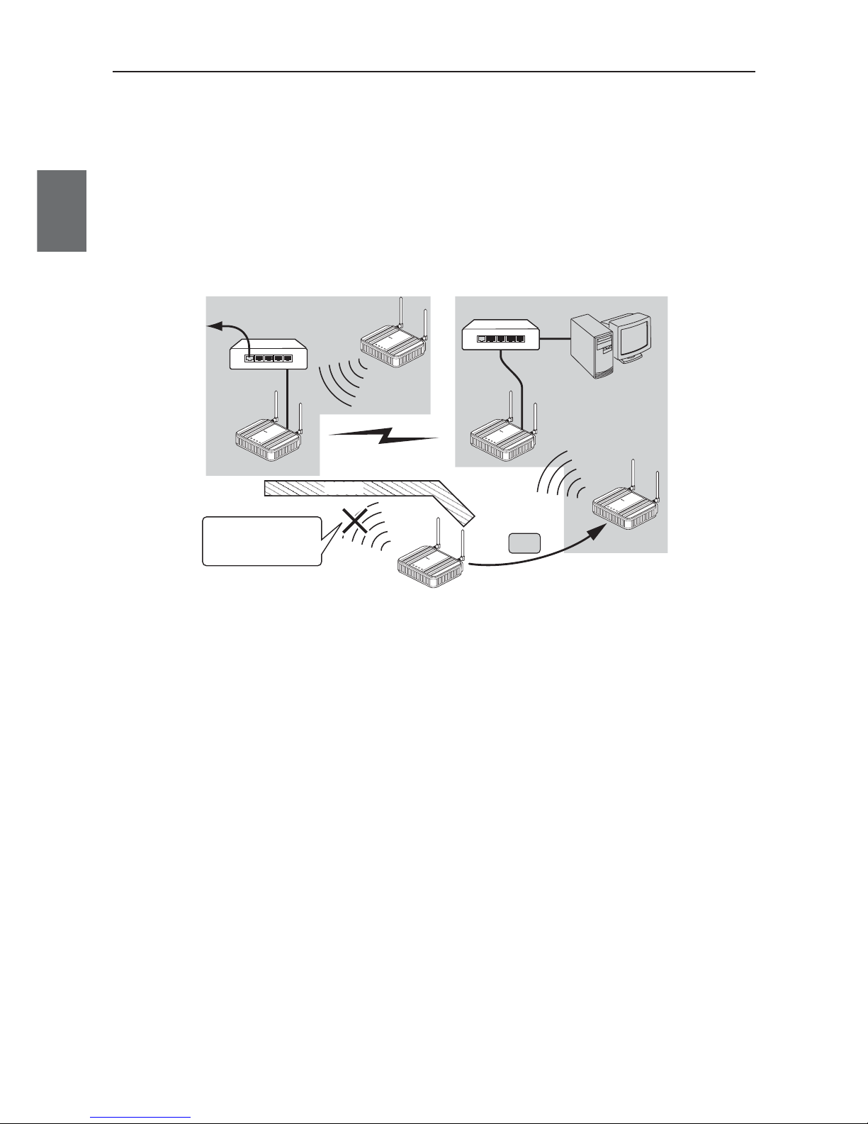
●
AP-to-AP (access point) bridging
In addition to communication between an access point and a client (slave), communication between access
points (between A and B in the figure) is available.This function is called AP-to-AP bridging.
AP-to-AP bridging can be up to 54Mbps [IEEE802.11a /IEEE802.11g], allowing connection between access
points.
Furthermore, an obstacle can be avoided that prevent direct communication between a client (slave, C in the
figure) and its closest access point (A), by moving close to other access point (B) without any obstacle.
This function can be used also as a relay function (P.1.9, B) to expand a communication zone by wireless
connection.
* All access points that use AP-to-AP bridging must be configured to use the same channel.
* Up to 6 units can communicate with an access point at the same time.
* To use encryption, the same encryption key must be configured for the access points.
* Only "WEP RC4" and "OCB AES" can be used as encryption for AP-to-AP bridging.
* BSSID of respective access point must be registered for those that use AP-to-AP bridging.
In the figure above, [BSSID] of [B] must be registered to [A] and [BSSID] of [A] to [B].
* Configuring the same channel and SSID allows detection of BSSID of the others, making registration easier.
* To use roaming, the same SSID must be configured for the access points (A and B).
* AP-to-AP bridging requires the same setup of Super AG (Yes or No).
* AP-to-AP bridging is not available at the channel where DFS function is provided.
C
L
A
N
M
O
D
E
P
O
WE
R
W
I
R
E
LE
S
S
L
A
N
M
O
D
E
P
O
W
E
R
W
I
R
E
L
E
S
S
L
A
N
RS
S
I
P
OW
E
R
W
I
RE
L
E
S
S
A
A
A
B
BB
C
CC
W
E
7
0
C
L
F
A
W
I
R
E
L
E
S
S
L
A
N
A
C
C
E
S
S
P
O
I
N
T
W
E
7
0
A
P
F
A
W
I
R
E
L
E
S
S
LA
N
A
C
C
E
S
S
P
O
I
N
T
W
E
7
0
A
P
F
A
W
I
R
E
L
E
S
S
L
A
N
A
C
C
E
S
S
PO
I
N
T
L
A
N
R
S
S
I
P
O
WE
R
W
I
R
E
L
E
S
S
W
E
7
0
C
L
F
A
W
I
R
E
L
E
S
S
L
A
N
A
C
C
E
S
S
P
O
I
N
T
L
A
N
R
S
S
I
P
O
WE
R
W
I
R
E
L
E
S
S
W
E
7
0
C
L
F
A
W
I
R
E
L
ES
S
L
A
N
A
C
C
E
S
S
P
O
I
N
T
Obstacle
WE70-AP
WE70-AP
WE70-CL
WE70-CL
WE70-CL
AP-to-AP bridging
AP-CL
communication
AP-CL
communication
Moves to [B] since the
obstacle interfere the
unit with the direct
communication with [A].
Move
To wired LAN
HUB
HUB
1-5
Chapter 1. Overview
1
Overview
●
Ample wireless LAN security function (* not configured on factory shipment status)
This wireless unit set provides the latest standardized security.It allows communication in FA wireless LAN
only and rejects communication with other wireless LAN, enhancing security.
Following functions are provided for security required in wireless LAN communication.
MAC address filtering ................Access can be permitted to clients (slaves) with MAC addresses registered
in an access point for communication in the same wireless network group.
WEP (RC4)/OCB AES ..............Data transmitted in a wireless network is encrypted based on a set string for
security.For AP-to-AP bridging, OCB AES is recommended.
* Communication will not be available if the other part of the communication uses a different
encryption method or a cryptographic key.
• Others
TKIP/AES ..................................These encryption methods can only be used for a wireless LAN computer
with Windows XP (Service Pack1) with a certain update program applied or
with Windows XP (Service Pack2).
* "TKIP" is stronger than "WEP (RC4)".
* "AES" is a next-generation encryption method stronger than "TKIP".
* "TKIP" and "AES" do not support AP-to-AP bridging.
WOC KEY..................................Omron's proprietary authentication method that uses a Pre-Shared Key as
with TKIP/AES.
* "WOC KEY" do not support AP-to-AP bridging.
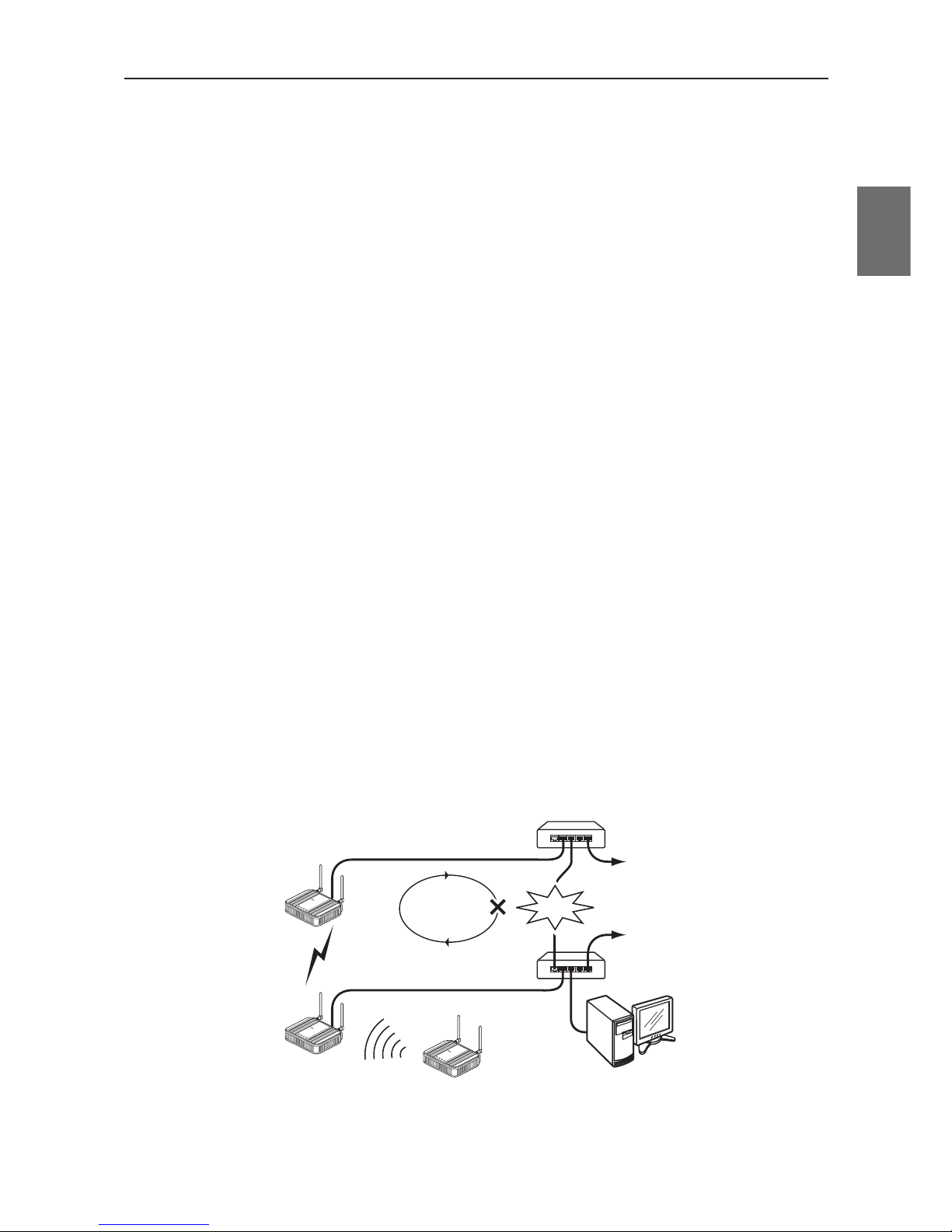
●
Spanning tree
This function is used to detect a loop of communication between bridges, avoid endless looping of packets,
and create an optimal route.
In a network example shown below, if spanning tree function is enabled for access points (A and B) a loop of
any route is detected and a route with lower priority (route A-B) is shut off as long as no failure is occurring.If
any communication failure occurs in a route between cascade-coupled hubs (route C-D), radio
communication between access points (A and B) is enabled to keep normal operation of the network.
If this function is not used, communication packets on the network endlessly flow through access points (B>D->C->A->B).
If the spanning tree function is being enabled, it will take about 30 seconds after inserting a LAN cable before
network communication becomes available,while its LAN indicator may be lit.
To construct a network using the spanning tree function, you must choose a switch or a hub that supports
IEEE802.1d spanning tree protocol.
C
D
To wired LAN
HUB
HUB
To wired LAN
LAN
MO
DE
POW
ER
WIREL
ESS
LAN
MO
D
E
P
O
WE
R
W
IR
E
LE
SS
AP-to-AP bridging
AP-CL communication
WE70-AP
WE70-AP
WE70-CL
Looping
Failure
LAN
MO
D
E
P
O
WE
R
W
I
R
E
L
E
SS
W
E
7
0C
L
F
A
W
I
R
EL
E
S
S
L
A
N
A
C
C
E
S
S
P
O
I
N
T
W
E
7
0-
A
P
F
A
W
I
R
E
L
E
S
S
L
A
N
AC
CE
S
S
P
O
I
N
T
W
E
7
0-
AP
FA
WIRE
L
ES
S
L
A
N
AC
C
E
S
S
P
O
INT
A
AA
B
B
B
Chapter 1. Overview
1-6
1
Overview
●
Super AG technology
This technology was developed by Atheros Communications in the U.S. for higher speed wireless LAN.
To use the Super AG with other wireless device, other devices must support "Super AG" as well.
Super AG setup must be the same for those that use AP-to-AP bridging.
* To use AP-to-AP bridging with configuration of [Super AG] as [Yes (Compressed)], a key index to be configured for WEP (RC4)/OCB
AES encryption must be configured as the same as those that use AP-to-AP bridging. Communication is unavailable if key indexes
differ.
●
Roaming
Providing more than one access point connected with wired LAN expands its wireless communication zone
by automatically switching to an access point with better radio wave status when a client (slave) is moved,
allowing use of wireless LAN while moving in a wide space such as a plant or a warehouse.
(Example: IEEE802.11g wireless LAN)
* To use roaming, the same wireless network name (SSID) and encryption must be configured for all access points and clients
(slaves).(Communication is unavailable if setup differs)
●
Connection terminal limiting function
This function the limits the number of clients (slaves) that can be connected to an access point at the same
time to prevent decrease in communication speed due to jammed connection.
* The value is 63 on factory shipment status.
L
A
N
M
O
D
E
P
O
W
E
R
W
I
R
E
L
E
S
S
W
E
7
0
C
L
F
A
W
I
R
E
L
E
S
S
L
A
N
A
C
C
E
S
S
P
O
IN
T
L
A
N
M
O
D
E
P
O
W
E
R
W
I
R
E
L
E
S
S
W
E
7
0
C
L
F
A
W
I
R
E
L
E
S
S
L
A
N
A
C
C
E
S
S
P
O
IN
T
To wired LAN
HUB
192.168.0.1
192.168.0.10 192.168.0.10
192.168.0.2
Wireless LAN terminal
Move
Connection is
switched if the
client moves
WE70-AP WE70-AP
WE70-CL
[802.11g:6CH]
[SSID:omronwe70wlan]
[802.11g:11CH]
[SSID:omronwe70wlan]
[SSID:omronwe70wlan] [SSID:omronwe70wlan]
L
A
N
M
O
D
E
P
O
W
E
R
W
I
R
E
L
E
S
S
W
E
7
0
A
P
F
A
W
I
R
E
L
E
S
S
L
A
N
A
C
C
E
S
S
P
O
I
N
T
L
A
N
M
O
D
E
P
O
W
E
R
W
I
R
E
L
E
S
S
W
E
7
0
A
P
F
A
W
I
R
E
L
E
S
S
L
A
N
A
C
C
E
S
S
P
O
I
N
T
* For communication using 2.4GHz band (IEEE802.11b/g), "channels" of access points must be configured with blank channels of 4 or
more between them to avoid radio interference.
Otherwise a part of a band may overlap and cause cross talk.
2400 2410 2420 2430 2440 2450
Frequency (MHz)
2460 2470 2480 2490
1CH
2CH
3CH
4CH
5CH
6CH
7CH
8CH
9CH
11CH
12CH
13CH
10CH
* For communication using 5GHz band [IEEE802.11a], radio interference will not occur as long as configured channels are different for
each other.
1-7
Chapter 1. Overview
1
Overview
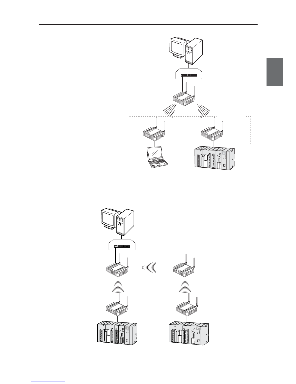
■
System Configuration
Connect an access point to the same network
(Ethernet) as PLC (programmable controller)
and/or PC (personal computer) for communication
with clients (slaves),through which PC data can be
shared and PLC data can be acquired.
LA
N
MO
DE
P
O
W
E
R
W
I
R
E
L
E
S
S
W
E
7
0
C
L
F
A
W
IR
E
L
E
S
S
L
A
N
A
C
C
E
S
S
P
O
I
N
T
LAN
M
O
D
E
P
O
W
E
R
W
I
R
E
L
E
S
S
W
E
7
0
C
L
F
A
W
I
R
E
L
E
S
S
L
A
N
A
C
C
E
S
S
P
O
I
N
T
Client (Slave)
WE70-CL
L
A
N
M
O
D
E
P
O
W
E
R
W
I
R
E
L
E
S
S
W
E
7
0
A
P
F
A
W
I
R
E
L
E
S
S
L
A
N
A
C
C
E
S
S
PO
I
N
T
Access Point
WE70-AP
PLC + Ethernet unit
PC
PC
Up to 63 units
HUB
Ethernet
●
AP-to-AP bridging
An access point is used as a repeater for communication with a client (slave).Access points used for this
function must register the others' BSSIDs.
LAN
MO
DE
P
OW
ER
W
IRE
L
ES
S
W
E
7
0
C
L
F
A
W
I
R
E
L
E
S
S
L
A
N
A
C
C
E
S
S
P
O
I
N
T
LAN
M
ODE
POW
ER
WIR
ELESS
W
E
7
0
C
L
F
A
W
I
R
E
L
E
S
S
L
A
N
A
C
C
E
S
S
P
O
I
N
T
Client (Slave)
WE70-CL
Client (Slave)
WE70-CL
L
A
N
M
O
D
E
P
O
W
E
R
W
IR
E
L
E
S
S
W
E
7
0
A
P
F
A
W
I
R
E
L
E
S
S
L
A
N
A
C
C
E
S
S
P
O
I
N
T
Access Point
WE70-AP
PC
L
A
N
M
O
D
E
P
O
W
E
R
W
IR
E
L
E
S
S
W
E
7
0
A
P
F
A
W
I
R
E
L
E
S
S
L
A
N
A
C
C
E
S
S
P
O
I
N
T
Access Point
WE70-AP
Repeater
HUB
Ethernet
* AP-to-AP bridging is not available at the channel where DFS function is provided.

Chapter 1. Overview
1-8
1
Overview
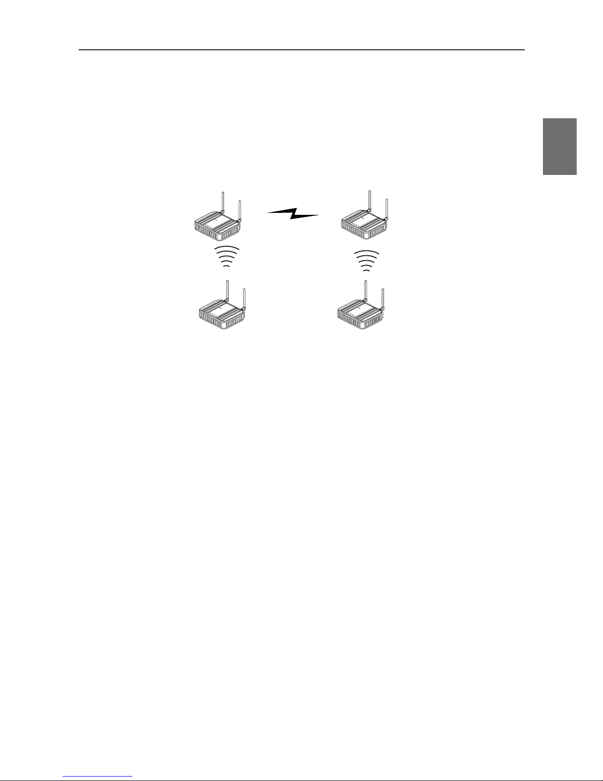
●
Roaming
Connect 2 or more access points to the same network (Ethernet) for communication with a client (slave).
Communication will be available with an access point closest to a client (slave) even if it is moved.
L
A
N
MO
D
E
P
OW
E
R
WI
RE
LE
SS
W
E
7
0
C
L
F
A
W
I
R
E
L
E
S
S
L
A
N
A
C
C
E
S
S
P
O
I
N
T
LAN
M
OD
E
POW
ER
WIRELESS
W
E
7
0
C
L
F
A
W
I
R
E
L
E
S
S
L
A
N
A
C
C
E
S
S
P
O
I
N
T
Client (Slave)
WE70-CL
L
A
N
M
O
D
E
P
O
W
E
R
W
IR
E
L
E
S
S
W
E
7
0
A
P
F
A
W
I
R
E
L
E
S
S
L
A
N
A
C
C
E
S
S
P
O
I
N
T
Access Point
WE70-AP
PLC
PC
L
A
N
M
O
D
E
P
O
W
E
R
W
IR
E
L
E
S
S
W
E
7
0
A
P
F
A
W
I
R
E
L
E
S
S
L
A
N
A
C
C
E
S
S
P
O
I
N
T
Access Point
WE70-AP
Move
Roaming
HUB
Ethernet
1-9
Chapter 1. Overview
1
Overview
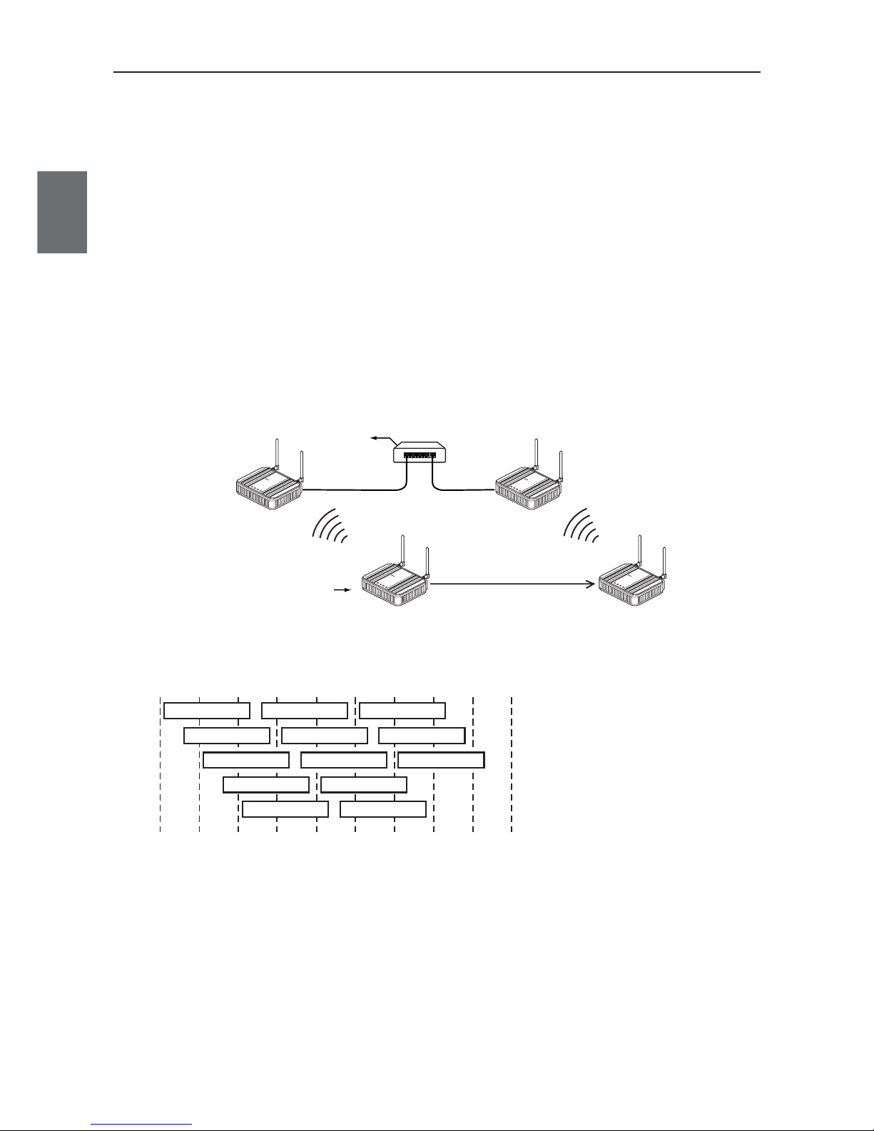
■
Relay Function
This function extends communication distance using other access point of AP-to-AP bridging as a wireless
repeater.
BSSID of respective access point must be registered for those that use AP-to-AP bridging.
Communication will be available between a distant access point and a client (slave) via a repeater.
* Up to 7 access points (including own unit) can be used for communication at the same time.
When one path is busy, other paths suspend communication. Because of this, all throughput is 1/6(1/ access number) by AP-to-AP
Bridging.
For the diagram of the maximum connection structure of communication AP-to-AP Bridging, see Ex 1 – 3 in “4-1 To Use AP-to-AP
Bridging” (P.4-2 and 4-3).
* All access points that use AP-to-AP bridging must be configured to use the same channel.
* For more information on AP-to-AP bridging, see "To Use AP-to-AP Bridging" (P.4-2).
Configuring the same SSID (3-3 Step 2. Configuring Wireless Network Name (SSID)(P.3-8)) allows detection of BSSID of the others,
making registration easier.
* If connection described below is made in addition to the example above, spanning tree function must be configured to avoid looping of
packets.(See P.1-5)
•A network has 3 or more wireless units using AP-to-AP bridging.
•Connecting access points (between A and B) using AP-to-AP bridging through a LAN cable
* AP-to-AP bridging is not available at the channel where DFS function is provided.
Connected AP is
switched to another
AP due to the
movement of CL.
192.168.0.10
BSS ID:00-00-0A-68-20-00
192.168.0.1
BSS ID:00-00-0A-68-20-01
192.168.0.2
AP-to-AP bridging
[802.11g:ch11]
[SSID:omronwe70wlan]
[802.11g:ch11]
L
A
N
M
O
D
E
P
O
W
E
R
W
I
R
E
L
E
S
S
W
E
7
0
A
P
F
A
W
IR
E
L
E
S
S
L
A
N
A
C
C
E
S
S
P
O
I
N
T
WE70-AP
L
A
N
M
O
D
E
P
O
W
E
R
W
I
R
E
L
E
S
S
W
E
7
0
A
P
F
A
W
IR
E
L
E
S
S
L
A
N
A
C
C
E
S
S
P
O
I
N
T
WE70-AP
WE70-CL
L
A
N
M
O
D
E
P
O
W
E
R
W
I
R
E
L
E
S
S
W
E
7
0
C
L
F
A
W
I
R
E
L
E
S
S
L
A
N
A
C
C
E
S
S
P
O
IN
T
L
A
N
M
O
D
E
P
O
W
E
R
W
I
R
E
L
E
S
S
W
E
7
0
C
L
F
A
W
I
R
E
L
E
S
S
L
A
N
A
C
C
E
S
S
P
O
IN
T
Chapter 1. Overview
1-10
1
Overview
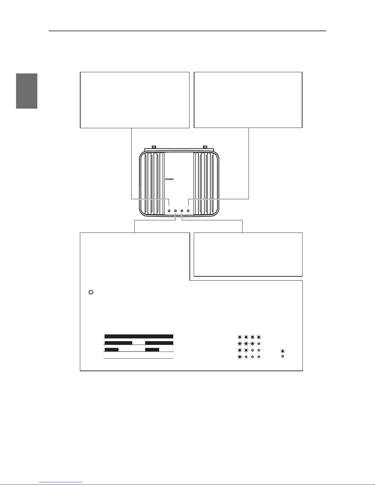
1-2. Components and Functions
■
Top View
WE70-AP
WE70-AP
LANMODE
FA WIRELESS LAN ACCESS POINT
POWER WIRELESS
[LAN] Indicator (Orange)
Displays a status of the wired LAN.
On: LAN connection is normal
Off: LAN is not being connected
Flashing: Data is being transmitted
[MODE] Indicator (Orange)(WE70-AP)
Displays an operation mode of the wireless unit.
*1 [RSSI] indicator for
WE70-CL
[RSSI] Indicator (Orange)(WE70-CL)
Displays receiving electric field intensity
by flashing.
Flashing: Simultaneous flashing of [MODE] and
[POWER] indicates setup initialization.
Using 802.11a: On
Using 802.11b/g: Off
When the RSSI button on top of the unit is pressed,
receiving electric field intensity is displayed on
[RSSI], [LAN], and [WIRELESS] indicators in 4
levels. The [POWER] indicator flashes at the same
time.Indication returns to its original status when 10
minutes passes or the button is pressed again.
RSSI
LANRSSIPOWER WIRELESS
LEVEL4
LEVEL3
LEVEL2
LEVEL1
LEVEL4
LEVEL3
LEVEL2
LEVEL1
Off
Off:
On
On
On
On:
On
On
......Stable Level.................
......Usable Level......
......Unstable Level..........
......Unusable Level..........
<Flashing>
<On>
[WIRELESS] Indicator (Orange)
Displays a status of the wireless LAN.
On: Radio communication is being established
with the wireless unit.
Off: Absence of wireless LAN terminal which is
communicating with the wireless unit, or no radio communication has been made for more
than 5 minutes (10 seconds for WE70-CL).
[POWER] Indicator (Green)
Displays a power source status and a wireless
unit operation mode.
On: The wireless unit is turned on.
Flashing: Simultaneous flashing of [POWER] and
[MODE]
*1
indicates setup initialization.
Alternate flashing of [POWER] and
[MODE] indicates startup.
 Loading...