

Page 1

OPERATION MANUAL
WE70-AP/CL
FA Wireless LAN Unit
Cat. No. N153-E1-01
Page 2

Page 3

1
This manual describes a wireless unit set conformance to
IEEE802.11a and IEEE802.11b/g* wireless LAN.
Please read this manual carefully and be sure you understand the
information provided before attempting to operate this product.
* IEEE802.11g is compatible with IEEE802.11b.
The Radio Law prohibits outdoor use of wireless LAN in
IEEE802.11a standard (5GHz band).
About this Manual
Page 4

2
Caution for the Radio Law on Wireless LAN
● The Radio Law prohibits outdoor use of wireless LAN in IEEE802.11a standard (5GHz band).
● Do not use it close to a person with a cardiac pacemaker.
Electromagnetic interference may affect it, putting his/her life at risk.
● Do not use it close to medical equipment.
Electromagnetic interference may affect the cardiac pacemaker to cause loss of human life.
● Do not use it close to an electric oven.
Electromagnetic interference may affect the medical equipment to cause loss of human life.
● Radio device in this product has been certified by the Radio Law. Do not disassemble or modify this
product.
Caution for Radio Interference with 2.4GHz Wireless LAN
Take the following precautions for communication by 2.4GHz (IEEE802.11b/g) wireless LAN.
Within this product's frequency range, industrial, scientific, and medical equipment, such as electric oven, as
well as RFID premises radio stations (license required) and specified low power radio station and ham radio
station (license not required) used in factory manufacturing lines are operated.
❍ Before using this device, confirm that no RFID premises radio station, specified low power radio station,
or ham radio station is operating close to it.
❍ If this product caused radio interference with an RFID premises radio station, immediately change the
product's frequency or stop radio emission, and contact OMRON representative for actions to take to
prevent cross talk.
Wireless LAN Standards Supported by This Product
This product supports the following wireless LAN standards:
• IEEE802.11a :Up to 54Mbps (5GHz band)
• IEEE802.11g :Up to 54Mbps (2.4GHz band)
• IEEE802.11b :Up to 11Mbps (2.4GHz band)
* IEEE802.11g is compatible with IEEE802.11b.
Page 5

3
Overview of This Product
• Accessory antenna of this product uses an external diversity type supporting 5GHz and 2.4GHz bands.
• This product provides DFS function that can automatically avoid radio interference by weather radar or
others while using IEEE802.11a.
* For more information on the DFS function, see "3-3 Configuring IP Address/SSID/Channel", "DFS
Function" (P.3-11).
• In addition to WEP RC4 and OCB AES encryption, TKIP, AES, and WOC KEY are supported.
• AP-to-AP bridging allows wireless connection between APs (access points).
• Spanning tree function can prevent problems related to network groups.
• This product supports 10BASE-T and 100BASE-TX wired LAN types are supported (automatic switching).
• Major setup of this product can be performed through a WWW browser.
• This product received Technical Standard Conformity Certification and does not require radio station
license.
• AP-to-AP bridging is not available at the channel where DFS function is provided.
Page 6

Notations
This document uses the following notation conventions:
" " :A name of a window of the operating system (OS), a setup screen menu item, or a setup screen under
a menu item is represented by " ".
[ ] :A name of a tab, icon, text box, check box, or setup item in a setup screen is represented by [ ].
< > : A name of a command button in a dialog box is represented by < >.
*Microsoft
®
Windows®Vista is indicated as Windows Vista.
Microsoft
®
Windows®XP Professional and Microsoft®Windows®XP Home Edition are indicated as
Windows XP.
Microsoft
®
Windows®2000 Professional is indicated as Windows 2000.
* Setup screen shown in this document may be different from those of your PC depending on your OS
version and preferences.
4
Page 7

5
Warranty and Limitations of Liability
1. WARRANTY
WARRANTY
OMRON's exclusive warranty is that the products are free from defects in Documents and workmanship
for a period of one year (or other period if specified) from date of sale by OMRON.
OMRON MAKES NO WARRANTY OR REPRESENTATION, EXPRESS OR IMPLIED, REGARDING
NON-INFRINGEMENT, MERCHANTABILITY, OR FITNESS FOR PARTICULAR PURPOSE OF THE
PRODUCTS. ANY BUYER OR USER ACKNOWLEDGES THAT THE BUYER OR USER ALONE HAS
DETERMINED THAT THE PRODUCTS WILL SUITABLY MEET THE REQUIREMENTS OF THEIR
INTENDED USE. OMRON DISCLAIMS ALL OTHER WARRANTIES, EXPRESS OR IMPLIED.
2. LIMITATIONS OF LIABILITY
LIMITATIONS OF LIABILITY
OMRON SHALL NOT BE RESPONSIBLE FOR SPECIAL, INDIRECT, OR CONSEQUENTIAL
DAMAGES, LOSS OF PROFITS OR COMMERCIAL LOSS IN ANY WAY CONNECTED WITH THE
PRODUCTS, WHETHER SUCH CLAIM IS BASED ON CONTRACT, WARRANTY, NEGLIGENCE, OR
STRICT LIABILITY.
In no event shall responsibility of OMRON for any act exceed the individual price of the product on which
liability is asserted.
IN NO EVENT SHALL OMRON BE RESPONSIBLE FOR WARRANTY, REPAIR, OR OTHER CLAIMS
REGARDING THE PRODUCTS UNLESS OMRON'S ANALYSIS COMFIRMS THAT THE PRODUCTS
WERE PROPERLY HANDLED, STORED, INSTALLED, AND MAINTAINED AND NOT SUBJECT TO
CONTAMINATION , ABUSE, MISUSE, OR INAPPROPRIATE MODIFICATION OR REPAIR.
3. Application Considerations
SUITABILITY FOR USE
OMRON shall not be responsible for conformity with any standards, codes, or regulations that apply to the
combination of products in the customer's application or use of the product.
At the customer's request, OMRON will provide applicable third party certification documents identifying
ratings and limitations of use that apply to the products. This information by itself is not sufficient for a
complete determination of the suitability of the products in combination with the end product, machine,
system, or other application or use.
The following are some examples of applications for which particular attention must be given. This is not
intended to be an exhaustive list of all possible uses of the products, nor is it intended to imply that the
uses listed may be suitable for the products:
• Outdoor use, uses involving potential chemical contamination or electrical interference, or conditions or
uses not described in this document.
Page 8

6
Do not use IEEE802.11 outdoors.
The Radio Law in Japan prohibits outdoor use of IEEE802.11a (5.2GHz/5.3GHz band).
Within this product's frequency range, industrial, scientific, and medical equipment as well as
RFID premises radio station (license required) and specified low power radio station (license
not required) used in factory manufacturing lines are operated.
(1) Before using this device, confirm that no RFID premises radio station or specified low power
radio station is operating close to it.
(2) If in case this product causes radio interference with an RFID premises radio station,
immediately change the product's frequency or stop radio emission, and contact OMRON
representative for actions to take to prevent cross talk (e.g. installation of a partition)
(3) If any other problem occurred due to this product, such as radio interference with an RFID
specified low power radio station, contact OMRON representative.
• Nuclear energy control systems, combustion systems, railroad systems, aviation systems, medical
equipment, amusement machines, vehicles, safety equipment and installations subject to separate
industry or government regulations.
• Systems, machines, and equipment that could present a risk to life or property.
Please know and observe all prohibitions of use applicable to the products.
NEVER USE THE PRODUCTS FOR AN APPLICATION INVOLVING SERIOUS RISK TO LIFE OR
PROPERTY WITHOUT ENSURING THAT THE SYSTEM AS A WHOLE HAS BEEN DESIGNED TO
ADDRESS THE RISKS, AND THAT THE OMRON PRODUCT IS PROPERLY RATED AND INSTALLED
FOR THE INTENDED USE WITHIN THE OVERALL EQUIPMENT OR SYSTEM.
4. Disclaimers
CHANGE IN SPECIFICATIONS
Product specifications and accessories may be changed at any time based on improvements and other
reasons.
It is our practice to change model numbers when published ratings or features are changed, or when
significant construction changes are made. However, some specifications of the product may be changed
without any notice. When in doubt, special model numbers may be assigned to fix or establish key
specifications for your application on your request. Please consult with your OMRON representative at
any time to confirm actual specifications of purchased product.
Approved Standards
Conforming Wireless Standards:
Japan: ARIB STD-T66,T71
USA: FCC part 15.247,401-407
Chinese domestic wireless standard [2002]353,[2002]227
Europe: EN 300 328,EN 301 893
Conforming Safety Standards:
cUL 60950-1(Listing)
EN 60950-1
Conforming EMC Standards: EN 301 489-3,EN 301 489-17
Conforming EMF Standards: EN 50371
Page 9

7
FCC WARNING
Changes or modifications not expressly approved by the party responsible for compliance could void the
user's authority to operate the equipment.
NOTICE
This equipment has been tested and found to comply with the limits for a Class B digital device, pur-
suant to part 15 of the FCC Rules. These limits are designed to provide
reasonable protection against harmful interference in a residential installation.
This equipment generates, uses and can radiate radio frequency energy and, if not installed and used in
accordance with the instructions, may cause harmful interference to radio communications. However,
there is no guarantee that interference will not occur in a particular installation. If this equipment does
cause harmful interference to radio or television reception, which can be determined by turning the
equipment off and on, the user is encouraged to try to correct the interference by one or more of the fol-
lowing measures:
• Reorient or relocate the receiving antenna
• Increase the separation between the equipment and receiver.
• Connect the equipment into an outlet on a circuit different from that to which the receiver is connected.
• Consult the dealer or an experienced radio/TV technician for help.
STP cables must be used for connection to host computer and/or peripherals in order to meet FCC
emission limits.
In according with 47 CFR Part15.407(e) U-Nll devices operating in 5.15-5.25GHz frequency bands are
restricted to indoor operations only.
This transmitter must not be co-located or operated in conjunction with any other antenna or transmitter.
This equipment complies with FCC radiation exposure limits set forth for uncontrolledequipment and
meets the FCC radio frequency (RF) Exposure Guidelines in Supplement C to OET65. This equipment
should be installed and operated with at least 20cm and more between the radiator and person's body
(excluding extremities: hands, wrists, feet and legs).
We, the manufacturer (name of the manufacturer) hereby declare that this equipment (type of the equip-
ment), model WE70-AP-EU/WE70-CL-EU is in compliance with the essential requirements and other
relevant provisions of Directive 1999/5/EC.
Applicable Countries
This product has been approved for wireless standards in the countries listed
below. This product cannot be used in any other countries.
WE70-AP/CL-US(United States), WE70-AP/CL-EU(Austria, Denmark, Finland, Germany, United Kingdom,
Ireland, Italy, Netherlands, Norway, Sweden, Switzerland, Spain, France, Belgium, Greece, Portugal, Czech,
Hungary, Poland, Slovenia, Slovakia), WE70-AP/CL-CN(China), WE70-AP/CL(Japan)
Conformance to EN Standards
Use a DC power line less than 3 m to conform to EN standards. If a power line
of 3 m or longer is required, extend the length at the Switching Power Supply's
primary side (i.e., the AC power line).
Conformance to UL Standards
Always use a Listing Class 2 power supply to conform to UL standards.
Using 5.8GHz in China
Gain approval from the wireless management body of a local province, autonomous region or city under the
direct jurisdiction for installing and using frequency of 5.8GHz in China.
Related body: Ministry of Information Industry (http://www.mii.gov.cn/)
Page 10
Safety Precautions
8
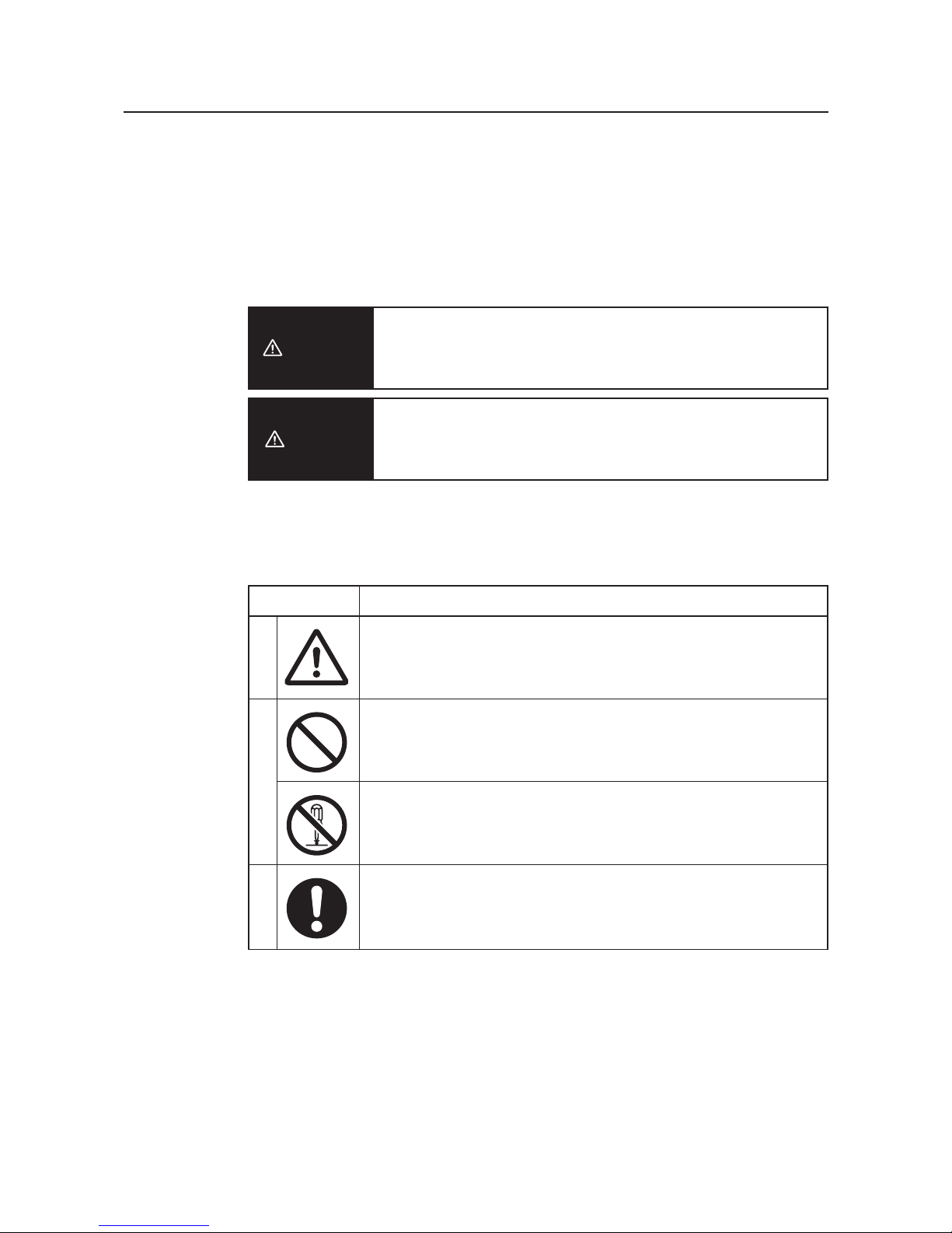
■ Indication for Safe Use
This document uses the following indication and symbols in precautions for safe use of WE70-AP/CL.
Precautions here specifies very important things related to safety and must be complied.
Indication and symbols include:
Warning Indication
Indicates a potentially hazardous situation which, if not avoided, will
result in minor or moderate injury, or may result in serious injury or
death. Additionally there may be significant property damage.
Indicates a potentially hazardous situation which, if not avoided,
may result in minor or moderate injury or in property damage.
■ Meanings of Alert Symbols
Caution
Warning
MeaningSymbol
Precautions
• General precaution
Indicates unspecified general precaution, warning, and hazard.
• General prohibition
Indicates unspecified general prohibition.
• Do Not Disassemble
Indicates that disassembly of equipment may cause an electrical
shock or injuries.
• General mandatory indication
Indicates unspecified general mandatory operation.
ProhibitionMandatory
Page 11
9
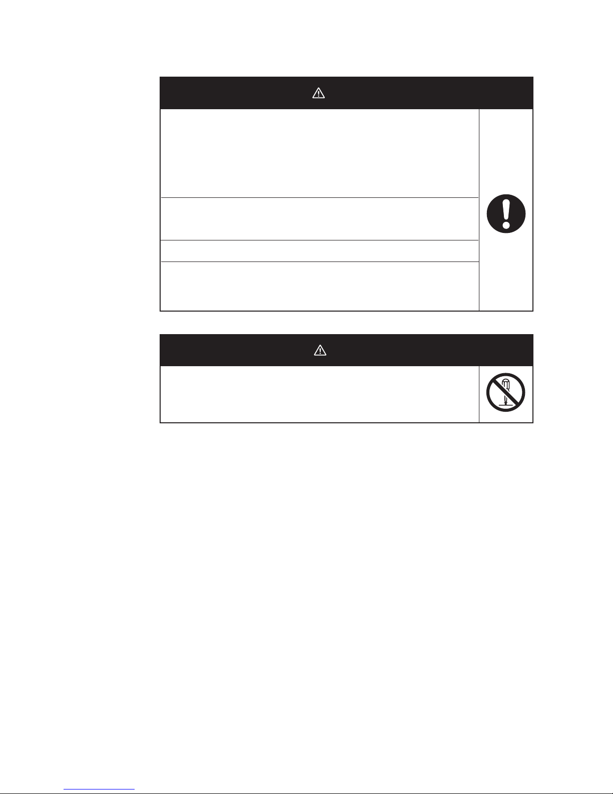
■ Warning Indication
DO NOT use this product without a protection circuit. Otherwise it may
result in heavy injuries or damage on property due to malfunction.
Dual or triple safety protection circuits, such as emergency stop, interlock,
or limit circuit, must be configured by external control circuit so that the
system should operate on safe side even if a failure of this product or an
error due to an external factor occurred.
This product uses electric wave for communication which may be broken
up temporarily due to its environment or usage.Safety of the system must
be maintained even in such a case.
Do not use this product for a real-time control application.
DO NOT use this product close to any medical equipment such as a
cardiac pacemaker as it may affect operation of such medical equipment
and may result in heavy injuries.
Warning
In rare cases, light electric shock, fire, or failure of this product may
occur.Do not disassemble, modify, fix, or touch inside of this product.
Disassembly and modification are prohibited by the Radio Law in each
country.
Caution
Page 12

10
Precautions for Safe Use
Observe the following precautions when using this product.
1) Dedicated packaging must be used for transportation of this product. Take precautions to prevent
excessive vibration or shock on the product or falling of the product.
2) Storage of this product must be within the specified environment. Allow the product to warm up to room
temperature for at least 3 hours after it has been stored at -10 degrees C or lower.
3) Use the product within the specified temperature and humidity ranges.
4) Do not use the product under the following environments:
• Locations subject to extreme temperature changes resulting in condensation
• Locations subject to static electricity, excessive noise, or electric fields
• Locations where the product may come into contact with water, oil, or chemicals
• Locations where corrosive gases or flammable gases are present
• Locations where large amounts of dust or dirt are present
• Locations subject to spatters, iron chips, or fillings
5) Do not use it outdoors (outside a control panel).
6) Use tape, cord, or other means to hold the product while adjusting the installation position to prevent the
product from damage due to failing.
7) Tighten the mounting screws to the specified torque of 4.4 to 5.3 in lb. (0.5 to 0.6 N
m)
8) Provide sufficient space around the product for heat dissipation. Install the products with a margin of
20mm or longer externally.
9) Do not reverse the power supply connection or connect the product to an AC power supply.
10) Use the correct power supply voltage.
11) Use the solid wire, 16 to 12 AWG for power supply. The exposed length of wire is 10 to 11mm(UL
Listing).
12) Do not lay communications cables and antenna cables near other high-voltage cables or power lines.
13) Setup is required after the installation or replacement of this product. Set up the product correctly
according to the manual, and be sure to confirm that communication is established before using it.
14) Do not apply excess vibrations or shock to this product. Do not drop this product.
15) Other wireless devices operating within the same frequency band may interfere with this product or be
adversely affected by this product. Therefore, be sure to perform the test provided with the product (e.g.,
installation tests) before operating it.
16) Make sure that the antenna is not disconnected during operation.
17) Do not use this product near other devices that may malfunction due to the electromagnetic waves
emitted by this product.
18) Turn OFF the power supply before performing any wiring or replacing devices.
19) Do not touch the product with wet hands.
20) Dispose of the product as industrial waste.
Page 13
Contents
11
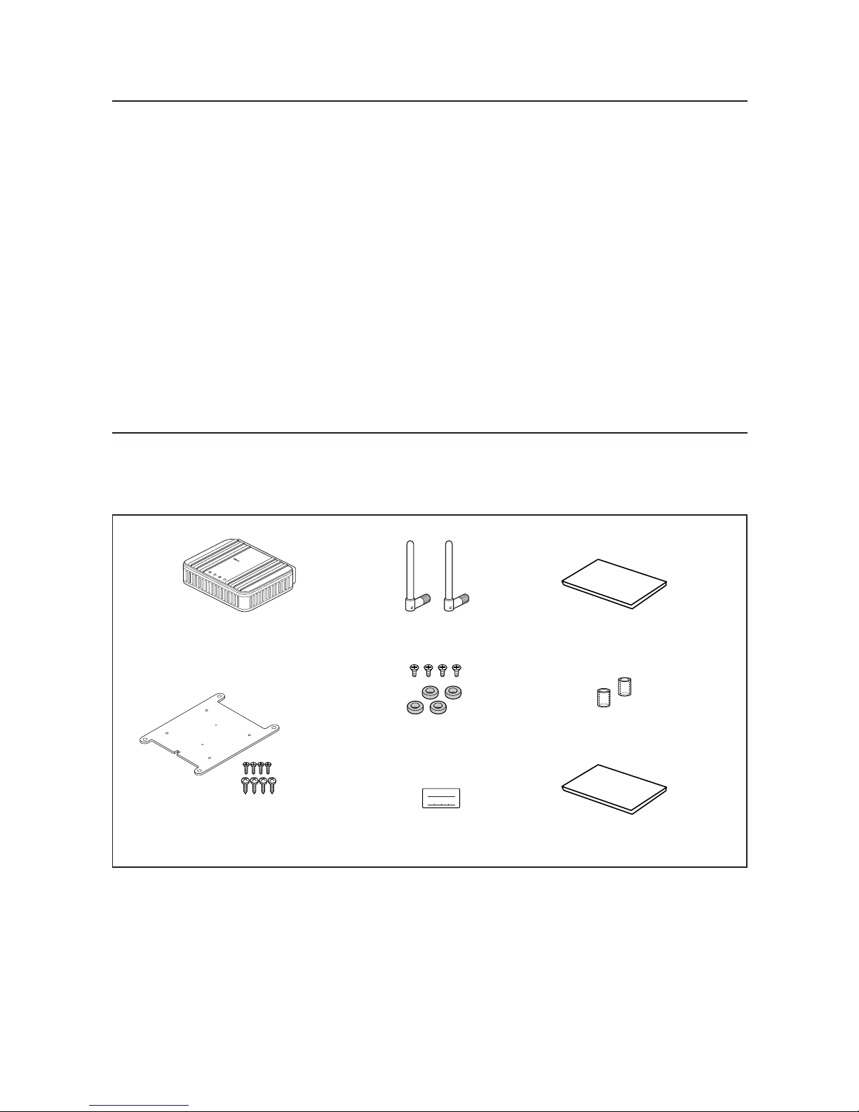
This product package includes the followings. (WE70-AP/CL-US/-EU/-CN)
Check if all of them are included in the package before using this product.
IP ADDRES
SUBNET MASK
Instruction Sheet x 3
EC Declaration of Conformity
Antenna Connector
Cover x 2
IP Address Label
Antenna x 2
Magnet x 4
(with 4 flat-head screws)
LAN
MODE
POWER
WIRELESS
WE70-AP
F
A
W
I
R
E
L
E
S
S
L
A
N
A
C
C
E
S
S
P
O
I
N
T
WE70-AP/WE70-CL
Mounting Bracket
(with 4 flat-head screws)
(with 4 tapping screws)
Precautions for Correct Use
Always heed these precautions to prevent faulty operation, malfunction, or adverse affect on the product's
performance and functionality.
1) Communication performance may be affected by its environment. Always confirm its operation before
using it.
2) Do not install its antenna where it is surrounded by metal, such as in a control panel.
3) Install the antenna so that it is as far away as possible from and not parallel to electric wires or metal
plates.
4) Do not use this product in areas exposed to extremely high humidity, near televisions or radios, near
motors or drills that emit sparks, near strong magnets, or near fluorescent lights.
5) Do not pull or bend cables with force.
Page 14
12
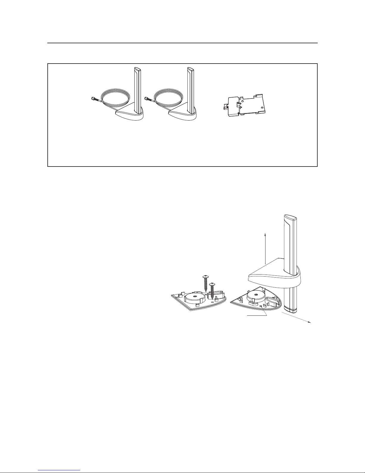
(As of December 2006)
<Magnetic-base Antenna>
WE70-AT001H is a non-directional antenna for 2.4/5GHz.
It can be installed where radio wave status is good, within a range of a given coaxial cable length (about 2m).
1 set with 2 antennas
Magnetic-base Antenna
Common for 2.4GHz and
5GHz bands
(WE70-AT001H)
DIN Rail Adapter
(WT30-FT001, 002)
Options
Assembly direction
Screw hole
Assembly direction
Assembly drawing
Page 15
Application Guide
13
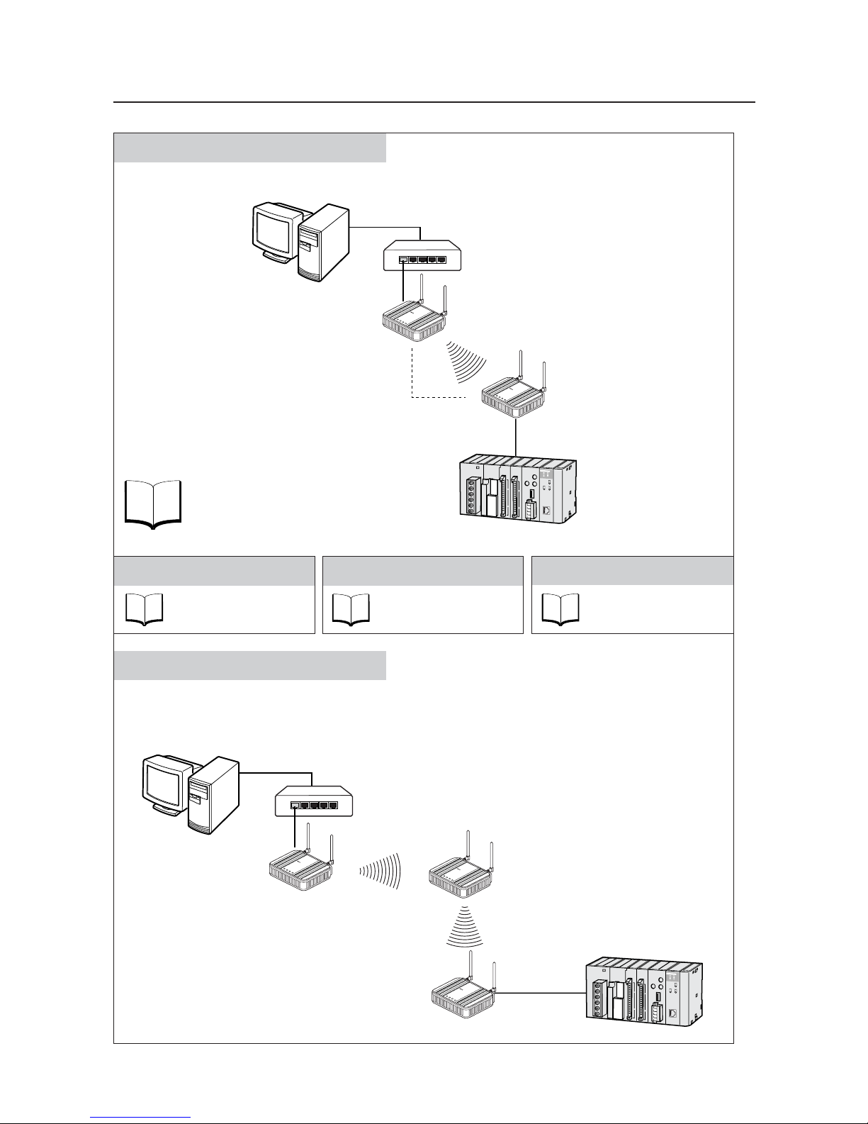
Basic Function
See
P.3-1
Refer to "Chapter 3. Basic Setup".
Constructs a network through radio communication.
AP-to-AP Bridging (Relay function)
An access point is used as a repeater for communication with a client (slave).
Under this system configuration, a client (CL-1) as a fixed station communicates with an access point (AP-2).
LAN
MODE
POWER
W
IREL
ES
S
W
E
7
0
C
L
F
A
W
I
R
E
L
E
S
S
L
A
N
A
C
C
E
S
S
P
O
I
N
T
Client (Slave)
WE70-CL
L
A
N
M
O
D
E
P
O
W
E
R
W
IR
E
L
E
S
S
W
E
7
0
-A
P
F
A
W
I
R
E
L
E
S
S
L
A
N
A
C
C
E
S
S
P
O
I
N
T
Access Point
WE70-AP
Access Point
WE70-AP
L
A
N
M
O
D
E
P
O
W
E
R
W
IR
E
L
E
S
S
W
E
7
0
-A
P
F
A
W
I
R
E
L
E
S
S
L
A
N
A
C
C
E
S
S
P
O
I
N
T
AP-to-AP
Bridging
Ethernet
HUB
Ethernet
PC
Pattern A
CL-1
CL-1
AP-2AP-2
AP-1AP-1
See
P. 3 - 12
Enhancing Security
Refer to "Chapter 3-4.
Configuring Encryption".
See
P. 6 - 2
Replacing Wireless Unit
Refer to "Chapter 6-1.
Replacing Wireless Unit".
See
P. 2 - 1
Installation
Refer to "Chapter 2.
Installation & Connection".
L
A
N
M
O
D
E
P
O
W
E
R
W
IR
E
L
E
S
S
W
E
7
0
A
P
F
A
W
I
R
E
L
E
S
S
L
A
N
A
C
C
E
S
S
P
O
I
N
T
LAN
MO
DE
PO
W
ER
W
I
RELE
S
S
W
E
7
0
C
L
F
A
W
I
R
E
L
E
S
S
L
A
N
A
C
C
E
S
S
P
O
I
N
T
Access Point
WE70-AP
Client (Slave)
WE70-CL
PLC
Ethernet
HUB
Ethernet
PC
Page 16
14
See
P.4-2
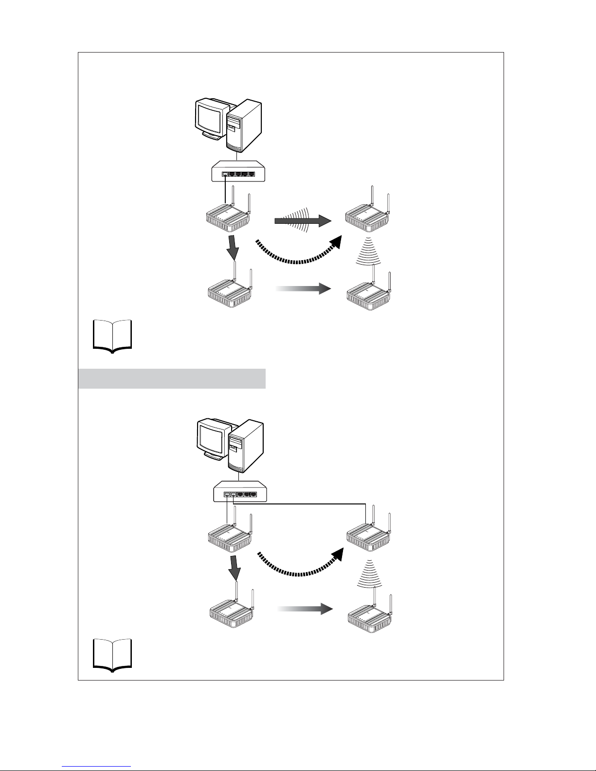
An access point is used as a repeater for communication with a moving client (slave).
A client (CL-1) moves between AP-1 and AP-2, switching communication paths.
Refer to "Chapter 4-1. To Use AP-to-AP Bridging".
See
P.4-22
Refer to "Chapter 4-9. Smart Roaming".
AP-1 and AP-2 are wired through HUB to communicate with a moving client (slave).
A client (CL-1) moves between AP-1 and AP-2, switching communication paths.
Access Point
WE70-AP
Access Point
WE70-AP
AP-to-AP
Bridging
L
A
N
M
O
D
E
P
O
W
E
R
W
I
R
E
L
E
S
S
W
E
7
0
A
P
F
A
W
I
R
E
L
E
S
S
L
A
N
A
C
C
E
S
S
P
O
I
N
T
L
A
N
M
O
D
E
PO
W
E
R
W
IR
E
L
E
S
S
W
E
7
0
A
P
F
A
W
I
R
E
L
E
S
S
L
A
N
A
C
C
E
S
S
P
O
I
N
T
LAN
M
O
DE
POW
E
R
W
I
RE
LE
S
S
W
E
7
0
C
L
F
A
W
I
R
E
L
E
S
S
L
A
N
A
C
C
E
S
S
P
O
I
N
T
L
AN
MO
DE
P
OWE
R
W
IRELES
S
W
E
7
0
C
L
F
A
W
IR
E
L
E
S
S
L
A
N
A
C
C
E
S
S
P
O
I
N
T
Client (Slave)
WE70-CL
Moving
(2) Path is switched
(2) Path is switched
(1) When communication
become unavailable
(3) Communication is
established through
a repeater
Access Point
WE70-AP
Access Point
WE70-AP
L
A
N
M
O
D
E
P
O
W
E
R
W
IR
E
L
E
S
S
W
E
7
0
A
P
F
A
W
I
R
E
L
E
S
S
L
A
N
A
C
C
E
S
S
P
O
I
N
T
L
A
N
M
O
D
E
PO
W
E
R
W
IR
E
L
E
S
S
W
E
7
0
-A
P
F
A
W
I
R
E
L
E
S
S
L
A
N
A
C
C
E
S
S
P
O
I
N
T
LAN
M
ODE
P
OW
ER
W
IRE
LES
S
W
E
7
0
-
C
L
F
A
W
I
R
E
L
E
S
S
L
A
N
A
C
C
E
S
S
P
O
I
N
T
LAN
MODE
POWER
WIRELESS
W
E
7
0
C
L
F
A
W
I
R
E
L
E
S
S
L
A
N
A
C
C
E
S
S
P
O
I
N
T
Client (Slave)
WE70-CL
Moving
(1) When communication
become unavailable
(3) Communication is
established with AP-2
HUB
Ethernet
HUB
Ethernet
Pattern B
Roaming for Wired Connection
PC
CL-1
CL-1
CL-1
CL-1
AP-2AP-2
AP-1AP-1
PC
CL-1
CL-1
CL-1
CL-1
AP-2AP-2
AP-1AP-1
Page 17

Manual Configuration
15
Chapter 1 Overview
Describes main features of this product.
1
Chapter 2
Installation &
Connection
Describes cautions for wireless unit installation and how to
connect the unit set.
2
Chapter 3 Basic Setup
Describes how to establish communication between an
access point and a client (slave) as well as a PLC using PC.
3
Chapter 4 Advanced Setup
Describes setup for communication between access points
and communication between clients through an access
point,as well as setup for stable communication.
4
Chapter 5 Setup Menu
Describes setup screens available for functions of this
wireless unit set.
5
Chapter 6
Replacement
Procedure
Describes how to save or initialize setup data for wireless
unit replacement.Read this chapter when necessary.
6
Appendices
Describes major troubleshooting, setup screen configuration,
and initial setup values.
Page 18

Table of Contents
16
About this manual ..................................................1
Warranty and Limitations of Liability ......................5
Safety Precautions.................................................8
Precautions for safe use ......................................10
Precautions for Correct Use.................................11
Contents...............................................................11
Options.................................................................12
Application Guide.................................................13
Manual Configuration...........................................15
Chapter 1 Overview
1-1. Features.............................................................................................................1-2
■ Major Features ..............................................................................................1-2
■ System Configuration ....................................................................................1-7
■ Relay Function ..............................................................................................1-9
1-2. Components and Functions .............................................................................1-10
■ Top View .....................................................................................................1-10
■ Rear View....................................................................................................1-11
Chapter 2 Installation & Connection
2-1. Installation..........................................................................................................2-2
■ Installation Location ......................................................................................2-2
■ Installation Precautions .................................................................................2-2
■ Precautions for Antenna Installation Location...............................................2-3
■ Dimensions ...................................................................................................2-5
■ Installation Method ........................................................................................2-5
2-2. Connection.........................................................................................................2-7
■ Notice for Wiring............................................................................................2-7
■ Main Unit Power Wiring.................................................................................2-7
■ LAN Cabling ..................................................................................................2-8
2-3. Connection Check ...........................................................................................2-10
■ Checking Setup Screen Access..................................................................2-10
Chapter 3 Basic Setup
3-1. Setup Workflow..................................................................................................3-2
3-2. Opening Setup Screen ......................................................................................3-3
Step 1. PC (Wired LAN) Setup ..........................................................................3-3
Step 2. Connecting ............................................................................................3-3
Step 3. Checking Setup Screen Access ............................................................3-4
Step 4. Monitoring Wireless Communication Status..........................................3-6
3-3. Configuring IP Address/SSID/Channel ..............................................................3-7
Step 1. IP Address Setup ..................................................................................3-7
Step 2. Configuring Wireless Network Name (SSID).........................................3-8
Step 3. Configuring Channel..............................................................................3-9
Step 4. Checking Communication ...................................................................3-11
Step 5. Other Setups .......................................................................................3-11
3-4. Configuring Encryption ....................................................................................3-12
■ To Enter Encryption Key Using ASCII Characters ......................................3-12
■ Entering Encryption Key..............................................................................3-13
■ Setup Example of Encryption Key...............................................................3-14
■ To Enter Encryption Key Using hexadecimal number.................................3-15
Page 19

17
■ Conversion Table from ASCII Character to hexadecimal number ..............3-16
■ To Generate Encryption Key Using Key Generator ....................................3-17
■ To Configure TKIP/AES/WOC KEY Encryption ..........................................3-18
3-5. Communicating with PLC ................................................................................3-20
Step 1. Preparing PLC & PC ...........................................................................3-20
Step 2. MAC Address Setup............................................................................3-21
Step 3. PLC Setup ...........................................................................................3-21
Step 4. Checking Communication with PLC ....................................................3-22
■Precautions for Communication with PLC....................................................3-22
Chapter 4 Advanced Setup
4-1. To Use AP-to-AP Bridging .................................................................................4-2
■ Communication with 2 or More Access Points ..............................................4-2
■ To Register BSSID ........................................................................................4-4
4-2. AP-to-AP Bridging Setup ...................................................................................4-5
Step 1. Configuring IP Address .........................................................................4-5
Step 2. Checking Own & Partner SSIDs............................................................4-6
Step 3. Checking Wireless Channel ..................................................................4-6
Step 4. Checking Own & Partner BSSIDs .........................................................4-6
Step 5. Checking Partner BSSID.......................................................................4-7
Step 6. Checking Receiving electric field strength.............................................4-8
Step 7. Checking AP-to-AP Bridging .................................................................4-9
4-3. Configuring Relay Function (Pattern A) ...........................................................4-10
Step 1. Changing Access Point SSID..............................................................4-11
Step 2. Configuring Client IP Address .............................................................4-11
Step 3. Checking Communication ...................................................................4-12
Step 4. Configuring Client-PLC Communication..............................................4-13
Step 5. PLC Setup ...........................................................................................4-14
Step 6. Checking PC-PLC Communication .....................................................4-14
4-4. Configuring Relay Function (Pattern B) ...........................................................4-15
Step 1. Configuring Smart Roaming ................................................................4-16
Step 2. Checking Smart Roaming ...................................................................4-16
Step 3. Checking PC-PLC Communication .....................................................4-17
4-5. To Set up MAC Address Filtering ....................................................................4-18
4-6. Using Spanning Tree Function ........................................................................4-19
■ Configuring Spanning Tree Function ..........................................................4-19
4-7. Using CL-to-CL Communication via AP...........................................................4-20
4-8. Limiting IEEE802.11b Communication ............................................................4-21
4-9. Smart Roaming ................................................................................................4-22
■ Scanning Frequency ...................................................................................4-22
■ Smart Roaming for 802.11a ........................................................................4-22
■ Smart Roaming for 802.11b/g .....................................................................4-23
4-10. Configuring Smart Roaming ............................................................................4-24
Step 1. Configuring IP Address .......................................................................4-24
Step 2. Changing Own & Partner SSIDs .........................................................4-25
Step 3. Checking Wireless Channel ................................................................4-26
Step 4. Configuring Client-PLC Communication..............................................4-26
Step 5. PLC Setup ...........................................................................................4-27
Step 6. Configuring Smart Roaming ................................................................4-28
Step 7. Checking Smart Roaming ...................................................................4-28
Step 8. Checking PC-PLC Communication .....................................................4-29
Page 20

18
Chapter 5 Setup Menu
5-1. Setup Screen & Functions .................................................................................5-2
■ Setup Screen ................................................................................................5-2
5-2. Setup Screen (WE70-AP) ..................................................................................5-3
■ Network Settings ...........................................................................................5-3
■ Wireless Settings ..........................................................................................5-4
■ Information ..................................................................................................5-13
■ Maintenance................................................................................................5-15
5-3. Setup Screen (WE70-CL) ................................................................................5-19
■ Setup...........................................................................................................5-19
■ Information ..................................................................................................5-26
■ Maintenance................................................................................................5-27
5-4. Limiting Setup Screen Access .........................................................................5-28
Chapter 6 Replacement Procedure
6-1. Replacing Wireless Unit.....................................................................................6-2
■ Saving Setup Data ........................................................................................6-2
■ Writing Saved Setup Data .............................................................................6-4
6-2. Restoring to Factory Shipment Status ...............................................................6-5
■ Using <INIT> Button......................................................................................6-5
■ Using Setup Screen ......................................................................................6-6
Appendices
Troubleshooting ..............................................................................................Appendices-2
Options ...........................................................................................................Appendices-3
■ Power ................................................................................................Appendices-3
■ Antenna.............................................................................................Appendices-3
■ Others ...............................................................................................Appendices-3
Initial Setup Value List ....................................................................................Appendices-4
■ WE70-AP ..........................................................................................Appendices-4
■ WE70-CL...........................................................................................Appendices-5
Rating .............................................................................................................Appendices-6
■ Wireless LAN Block (5GHz, 54Mbps; Common in AP/CL) ...............Appendices-6
■ Wireless LAN Block (2.4GHz, 11Mbps/54Mbps; Common in AP/CL)....Appendices-6
■ Common Spec for Wireless LAN Block (Common in AP/CL) ...........Appendices-6
■ Wired LAN Block (Common in AP/CL)..............................................Appendices-6
■ General Specification (Common in AP/CL).......................................Appendices-7
■ Other Functions.................................................................................Appendices-7
Dimensions .....................................................................................................Appendices-8
■ WE70-AP/CL.....................................................................................Appendices-8
■ Mounting Bracket ..............................................................................Appendices-8
■ Magnetic-base Antenna (WE70-AT001H: Optional) .........................Appendices-9
■ Extension Cable (WE70-CA5M: Optional) ........................................Appendices-10
Glossary..........................................................................................................Appendices-11
Revision History..............................................................................................Appendices-12
Page 21

Chapter 1
Overview
1-1. Features ..................................................................................1-2
■
Main Features ......................................................................1-2
■
System Configuration ..........................................................1-7
■
Relay Function ....................................................................1-9
1-2. Components and Functions ..................................................1-10
■
Top View ............................................................................1-10
■
Rear View ..........................................................................1-11
This chapter describes
Main features of a wireless unit set.
Page 22

Chapter 1. Overview
1-2
1
Overview
1-1. Features
WE70-AP/CL is a FA wireless LAN unit set conformance to IEEE802.11a/b/g.This section describes
features of the FA wireless LAN unit set WE70-AP/CL.
Connecting this wireless unit set to a PLC Ethernet unit allows wireless monitoring of facility
information through network as with wired connection.Ethernet unit functions can be used via radio
communications as they are.
(e.g. FINS communication service/socket/FTP server/e-mail transmission)
■
Main Features
●
FA wireless LAN units conformance to IEEE802.11a/b/g
This wireless unit set supports world-standard IEEE802.11a/b/g: both 5GHz band in IEEE 802.11a and
2.4GHz band in IEEE 802.11b/g.(Switched by setup and cannot be used simultaneously.)
FA sites having used various types of wireless devices (such as wireless LAN, RF-ID, WD30/WT30),
2.4GHz band has been congested.If you have difficulty in installing a new wireless system due to radio
interference, 5GHz band is recommended.5GHz band allow installation of additional wireless systems
without influences on existing wireless systems.(Up to 24 systems)
■ Channel assignment based on frequency band
802.11b/g: All of 13 channels (except 12CH and 13CH in United States)
(Up to 3 channels that can be used simultaneously)
(MHz)
1CH
2CH
3CH
4CH
5CH
6CH
7CH
8CH
9CH
10CH
11CH
12CH
13CH
2412
2417
2422
2427
2432
2437
2442
2447
2452
2457
2462
2467
2472
2.4GHz band
802.11a: All of 24 channels (up to 24 channels that can be used simultaneously)
globally common, indoors only
(MHz) 8CH All Countries (except China)
36CH
5180
100CH
5500
104CH
5520
108CH
5540
112CH
5560
116CH
5580
120CH
5600
124CH
5620
128CH
5640
132CH
5660
136CH
5680
140CH
5700
40CH
5200
44CH
5220
48CH
5240
52CH
5260
56CH
5280
60CH
5300
64CH
5320
(MHz)
5GHz band
(MHz) 5CH United States and China
149CH
5745
153CH
5765
157CH
5785
161CH
5805
165CH
5825
11CH All Countries (except China and Japan)
Standards IEEE 802.11a IEEE802.11b IEEE 802.11g
Maximum Speed 54Mbit/s 11Mbit/s 54Mbit/s
Frequency Band 5GHz band 2.4GHz band 2.4GHz band
Modulation OFDM DS-SS OFDM
• 5 times higher in speed
than 11b
• Noise resistant
• Less cross talk with other
devices
• All of 24 channels can be
used at the same time
• Wide selection of
products
•
Long communication
distance
• Can be used
outdoors
• 5 times higher in speed
than 11b
• Less vulnerable to
obstacles
• Long communication
distance
• Compatible with 11b
• Can be used outdoors
Characteristics
*You can chose a model for the country to use.
WE70-AP/CL :Japan
WE70-AP/CL-US :United States
WE70-AP/CL-EU :Europe
WE70-AP/CL-CN :China
Page 23

1-3
Chapter 1. Overview
1
Overview
●
Transmission power switching function
This wireless unit set can configure 3 levels of radio field intensity for transmission.This allows easier
installation of multiple wireless systems in one production site.Configuring the best transmission power for
an installed system should minimize influence on other systems.
Assuming high wireless transmission power as 1.0, middle and low transmission power can be indicated
as 0.5 and 0.25 respectively.
●
Wireless communication distance
Wireless communication distance depends on installation environment and communication frequency.
Use followings as guidelines.
• IEEE802.11a
54Mbps communication: ca. 40m (indoors: Clear view)
• IEEE802.11b/g
54Mbps (2.4GHz) communication: ca. 60m (indoors: Clear view)
●
Receiving electric field strength monitoring function
RSSI (Receive Signal Strength Indicator) on CL shows a radio status.
A radio communication status is displayed on LEDs on the unit.
●
Multiple sets of units installation is available in one zone
Using different channels (frequencies) in one zone prevents interference.
Up to 3 and 24 systems can be configured for 2.4GHz and 5GHz bands respectively.
●
Noise-resistance in FA sites
Noise resistance is the same level as that for installation in control panel of Omron's FA
equipment.(Equivalent to PLC)
The power supply is typical 24VDC in FA sites.Moreover, it is resistant against instantaneous power
interruption in the same level as FA equipment, allowing stable operation under continuous motion.
●
Optionally magnetic-base antenna can be provided.
Magnet allows easy installation of an antenna on a metallic part of a control panel
You can install a wireless unit set inside a control panel while its antenna outside the control panel.
Magnetic-base antenna contributes to cost reduction for installation.
●
Easy installation & setup
This wireless unit can be easily installed on a DIN rail.
(DIN rail mounting bracket: For options (WT30-FT001/FT002))
Setting is conducted in a web browser on your PC.
●
Smart roaming
When a radio wave status of current access point gets worse due to movement or relocation of WE70-CL
(slave), communication can be made through other access point (WE70-AP) with better radio wave
status.
●
DFS (Dynamic Frequency Selection)
As some channels (52CH - 64CH, 100CH-140CH) have been already used by air traffic control radars
and weather radars, a mechanism (DFS) is necessary to detect the radars.
When one of these channel is set, DFS scans radio waves for 1 minute after power-on of an access point
and allows use of the channel only if it is not used.
If radio waves of an air traffic control radar or a weather radar is detected while wireless LAN is under
operation, use of the channel is stopped within 10 seconds and switched to other channel.
Page 24
Chapter 1. Overview
1-4
1
Overview
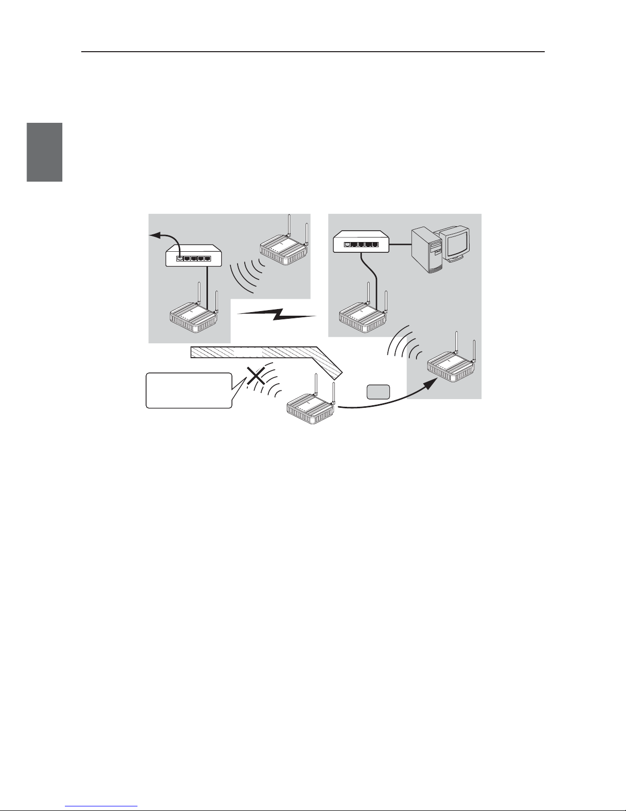
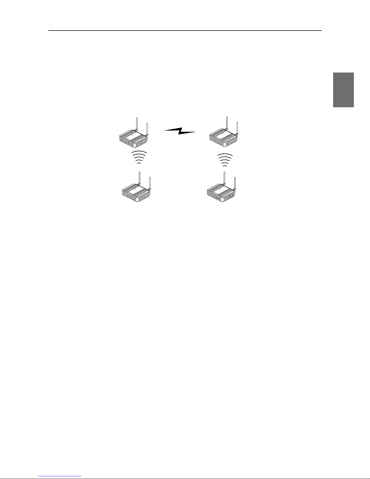
●
AP-to-AP (access point) bridging
In addition to communication between an access point and a client (slave), communication between access
points (between A and B in the figure) is available.This function is called AP-to-AP bridging.
AP-to-AP bridging can be up to 54Mbps [IEEE802.11a /IEEE802.11g], allowing connection between access
points.
Furthermore, an obstacle can be avoided that prevent direct communication between a client (slave, C in the
figure) and its closest access point (A), by moving close to other access point (B) without any obstacle.
This function can be used also as a relay function (P.1.9, B) to expand a communication zone by wireless
connection.
* All access points that use AP-to-AP bridging must be configured to use the same channel.
* Up to 6 units can communicate with an access point at the same time.
* To use encryption, the same encryption key must be configured for the access points.
* Only "WEP RC4" and "OCB AES" can be used as encryption for AP-to-AP bridging.
* BSSID of respective access point must be registered for those that use AP-to-AP bridging.
In the figure above, [BSSID] of [B] must be registered to [A] and [BSSID] of [A] to [B].
* Configuring the same channel and SSID allows detection of BSSID of the others, making registration easier.
* To use roaming, the same SSID must be configured for the access points (A and B).
* AP-to-AP bridging requires the same setup of Super AG (Yes or No).
* AP-to-AP bridging is not available at the channel where DFS function is provided.
C
L
A
N
M
O
D
E
P
O
WE
R
W
I
R
E
LE
S
S
L
A
N
M
O
D
E
P
O
W
E
R
W
I
R
E
L
E
S
S
L
A
N
RS
S
I
P
OW
E
R
W
I
RE
L
E
S
S
A
A
A
B
BB
C
CC
W
E
7
0
C
L
F
A
W
I
R
E
L
E
S
S
L
A
N
A
C
C
E
S
S
P
O
I
N
T
W
E
7
0
A
P
F
A
W
I
R
E
L
E
S
S
LA
N
A
C
C
E
S
S
P
O
I
N
T
W
E
7
0
A
P
F
A
W
I
R
E
L
E
S
S
L
A
N
A
C
C
E
S
S
PO
I
N
T
L
A
N
R
S
S
I
P
O
WE
R
W
I
R
E
L
E
S
S
W
E
7
0
C
L
F
A
W
I
R
E
L
E
S
S
L
A
N
A
C
C
E
S
S
P
O
I
N
T
L
A
N
R
S
S
I
P
O
WE
R
W
I
R
E
L
E
S
S
W
E
7
0
C
L
F
A
W
I
R
E
L
ES
S
L
A
N
A
C
C
E
S
S
P
O
I
N
T
Obstacle
WE70-AP
WE70-AP
WE70-CL
WE70-CL
WE70-CL
AP-to-AP bridging
AP-CL
communication
AP-CL
communication
Moves to [B] since the
obstacle interfere the
unit with the direct
communication with [A].
Move
To wired LAN
HUB
HUB
Page 25
1-5
Chapter 1. Overview
1
Overview
●
Ample wireless LAN security function (* not configured on factory shipment status)
This wireless unit set provides the latest standardized security.It allows communication in FA wireless LAN
only and rejects communication with other wireless LAN, enhancing security.
Following functions are provided for security required in wireless LAN communication.
MAC address filtering ................Access can be permitted to clients (slaves) with MAC addresses registered
in an access point for communication in the same wireless network group.
WEP (RC4)/OCB AES ..............Data transmitted in a wireless network is encrypted based on a set string for
security.For AP-to-AP bridging, OCB AES is recommended.
* Communication will not be available if the other part of the communication uses a different
encryption method or a cryptographic key.
• Others
TKIP/AES ..................................These encryption methods can only be used for a wireless LAN computer
with Windows XP (Service Pack1) with a certain update program applied or
with Windows XP (Service Pack2).
* "TKIP" is stronger than "WEP (RC4)".
* "AES" is a next-generation encryption method stronger than "TKIP".
* "TKIP" and "AES" do not support AP-to-AP bridging.
WOC KEY..................................Omron's proprietary authentication method that uses a Pre-Shared Key as
with TKIP/AES.
* "WOC KEY" do not support AP-to-AP bridging.
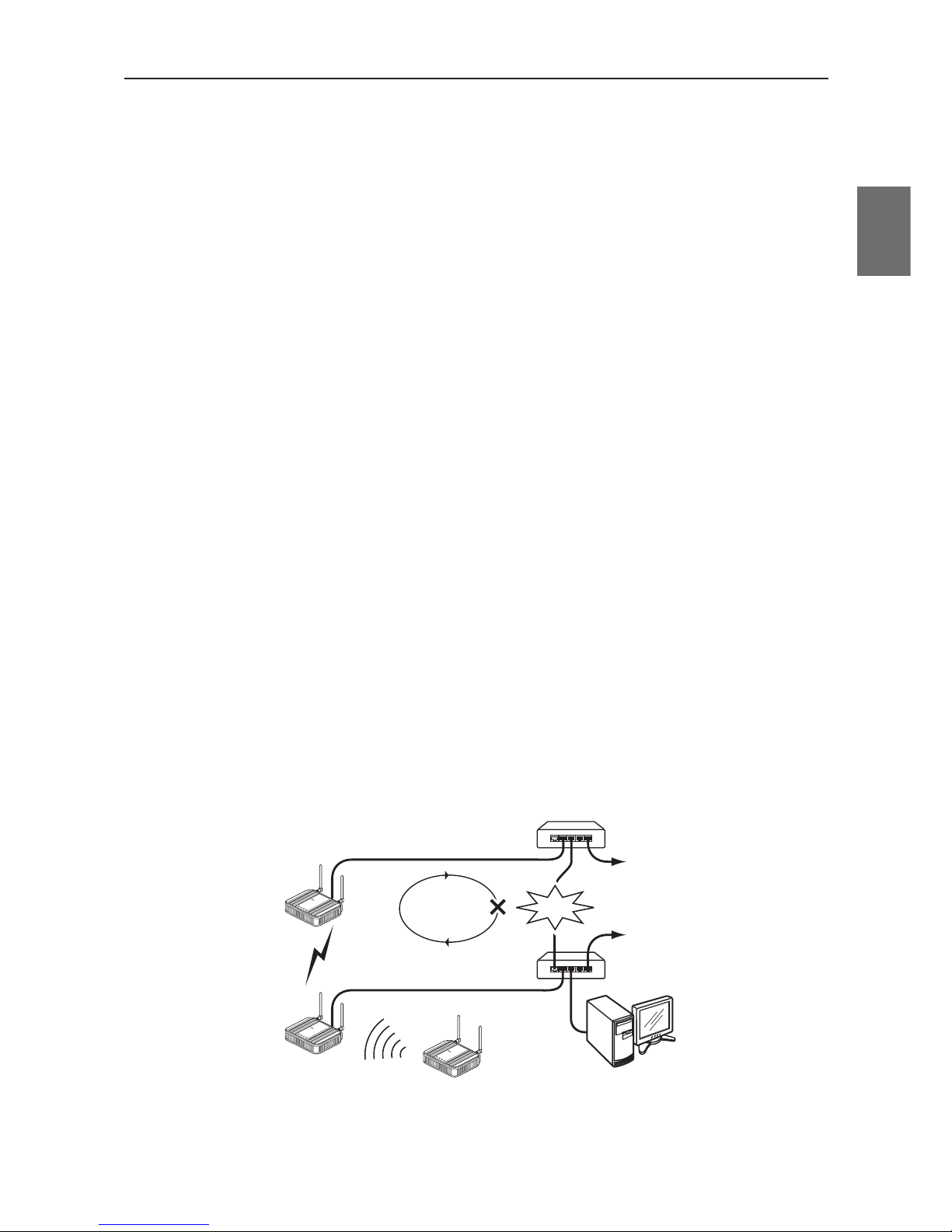
●
Spanning tree
This function is used to detect a loop of communication between bridges, avoid endless looping of packets,
and create an optimal route.
In a network example shown below, if spanning tree function is enabled for access points (A and B) a loop of
any route is detected and a route with lower priority (route A-B) is shut off as long as no failure is occurring.If
any communication failure occurs in a route between cascade-coupled hubs (route C-D), radio
communication between access points (A and B) is enabled to keep normal operation of the network.
If this function is not used, communication packets on the network endlessly flow through access points (B>D->C->A->B).
If the spanning tree function is being enabled, it will take about 30 seconds after inserting a LAN cable before
network communication becomes available,while its LAN indicator may be lit.
To construct a network using the spanning tree function, you must choose a switch or a hub that supports
IEEE802.1d spanning tree protocol.
C
D
To wired LAN
HUB
HUB
To wired LAN
LAN
MO
DE
POW
ER
WIREL
ESS
LAN
MO
D
E
P
O
WE
R
W
IR
E
LE
SS
AP-to-AP bridging
AP-CL communication
WE70-AP
WE70-AP
WE70-CL
Looping
Failure
LAN
MO
D
E
P
O
WE
R
W
I
R
E
L
E
SS
W
E
7
0C
L
F
A
W
I
R
EL
E
S
S
L
A
N
A
C
C
E
S
S
P
O
I
N
T
W
E
7
0-
A
P
F
A
W
I
R
E
L
E
S
S
L
A
N
AC
CE
S
S
P
O
I
N
T
W
E
7
0-
AP
FA
WIRE
L
ES
S
L
A
N
AC
C
E
S
S
P
O
INT
A
AA
B
B
B
Page 26
Chapter 1. Overview
1-6
1
Overview
●
Super AG technology
This technology was developed by Atheros Communications in the U.S. for higher speed wireless LAN.
To use the Super AG with other wireless device, other devices must support "Super AG" as well.
Super AG setup must be the same for those that use AP-to-AP bridging.
* To use AP-to-AP bridging with configuration of [Super AG] as [Yes (Compressed)], a key index to be configured for WEP (RC4)/OCB
AES encryption must be configured as the same as those that use AP-to-AP bridging. Communication is unavailable if key indexes
differ.
●
Roaming
Providing more than one access point connected with wired LAN expands its wireless communication zone
by automatically switching to an access point with better radio wave status when a client (slave) is moved,
allowing use of wireless LAN while moving in a wide space such as a plant or a warehouse.
(Example: IEEE802.11g wireless LAN)
* To use roaming, the same wireless network name (SSID) and encryption must be configured for all access points and clients
(slaves).(Communication is unavailable if setup differs)
●
Connection terminal limiting function
This function the limits the number of clients (slaves) that can be connected to an access point at the same
time to prevent decrease in communication speed due to jammed connection.
* The value is 63 on factory shipment status.
L
A
N
M
O
D
E
P
O
W
E
R
W
I
R
E
L
E
S
S
W
E
7
0
C
L
F
A
W
I
R
E
L
E
S
S
L
A
N
A
C
C
E
S
S
P
O
IN
T
L
A
N
M
O
D
E
P
O
W
E
R
W
I
R
E
L
E
S
S
W
E
7
0
C
L
F
A
W
I
R
E
L
E
S
S
L
A
N
A
C
C
E
S
S
P
O
IN
T
To wired LAN
HUB
192.168.0.1
192.168.0.10 192.168.0.10
192.168.0.2
Wireless LAN terminal
Move
Connection is
switched if the
client moves
WE70-AP WE70-AP
WE70-CL
[802.11g:6CH]
[SSID:omronwe70wlan]
[802.11g:11CH]
[SSID:omronwe70wlan]
[SSID:omronwe70wlan] [SSID:omronwe70wlan]
L
A
N
M
O
D
E
P
O
W
E
R
W
I
R
E
L
E
S
S
W
E
7
0
A
P
F
A
W
I
R
E
L
E
S
S
L
A
N
A
C
C
E
S
S
P
O
I
N
T
L
A
N
M
O
D
E
P
O
W
E
R
W
I
R
E
L
E
S
S
W
E
7
0
A
P
F
A
W
I
R
E
L
E
S
S
L
A
N
A
C
C
E
S
S
P
O
I
N
T
* For communication using 2.4GHz band (IEEE802.11b/g), "channels" of access points must be configured with blank channels of 4 or
more between them to avoid radio interference.
Otherwise a part of a band may overlap and cause cross talk.
2400 2410 2420 2430 2440 2450
Frequency (MHz)
2460 2470 2480 2490
1CH
2CH
3CH
4CH
5CH
6CH
7CH
8CH
9CH
11CH
12CH
13CH
10CH
* For communication using 5GHz band [IEEE802.11a], radio interference will not occur as long as configured channels are different for
each other.
Page 27
1-7
Chapter 1. Overview
1
Overview
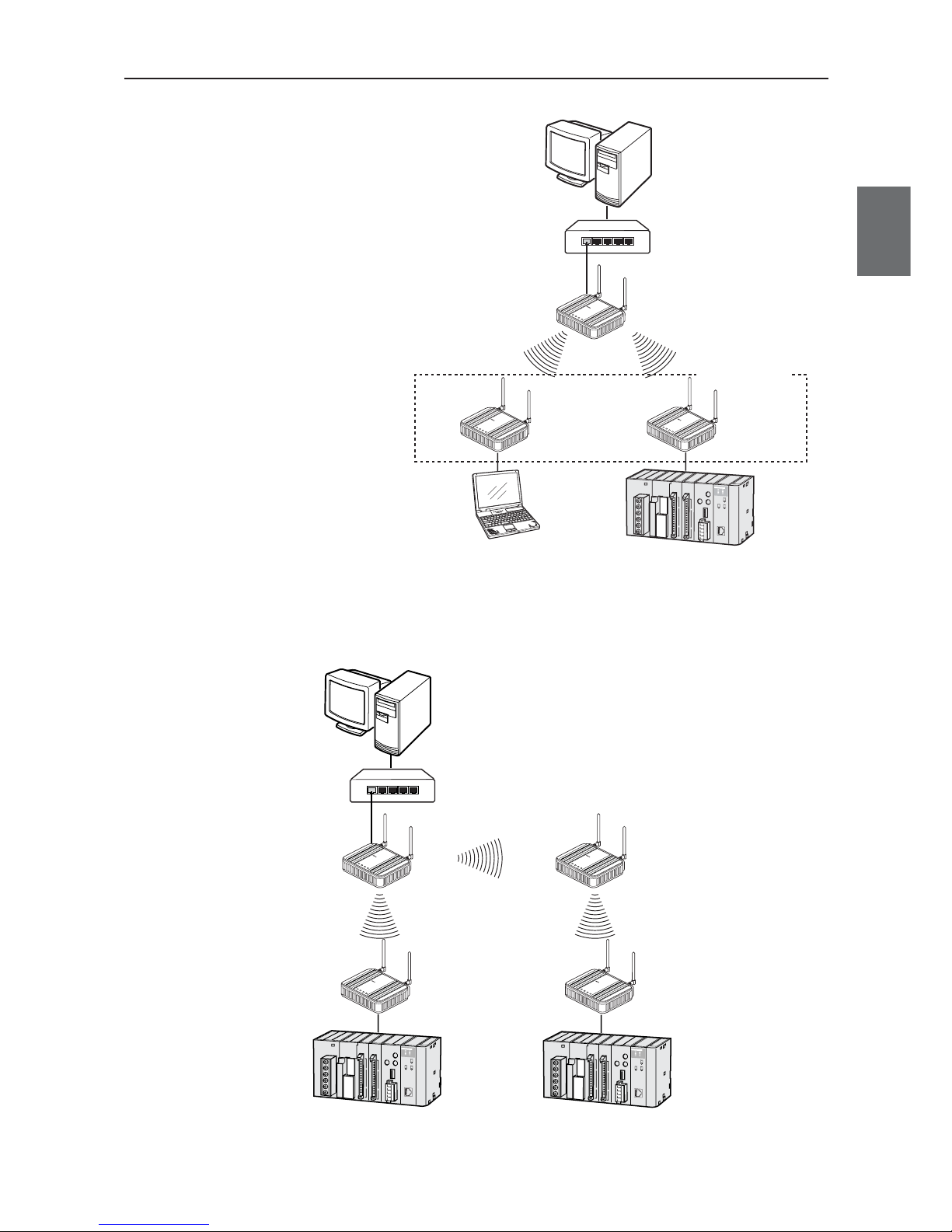
■
System Configuration
Connect an access point to the same network
(Ethernet) as PLC (programmable controller)
and/or PC (personal computer) for communication
with clients (slaves),through which PC data can be
shared and PLC data can be acquired.
LA
N
MO
DE
P
O
W
E
R
W
I
R
E
L
E
S
S
W
E
7
0
C
L
F
A
W
IR
E
L
E
S
S
L
A
N
A
C
C
E
S
S
P
O
I
N
T
LAN
M
O
D
E
P
O
W
E
R
W
I
R
E
L
E
S
S
W
E
7
0
C
L
F
A
W
I
R
E
L
E
S
S
L
A
N
A
C
C
E
S
S
P
O
I
N
T
Client (Slave)
WE70-CL
L
A
N
M
O
D
E
P
O
W
E
R
W
I
R
E
L
E
S
S
W
E
7
0
A
P
F
A
W
I
R
E
L
E
S
S
L
A
N
A
C
C
E
S
S
PO
I
N
T
Access Point
WE70-AP
PLC + Ethernet unit
PC
PC
Up to 63 units
HUB
Ethernet
●
AP-to-AP bridging
An access point is used as a repeater for communication with a client (slave).Access points used for this
function must register the others' BSSIDs.
LAN
MO
DE
P
OW
ER
W
IRE
L
ES
S
W
E
7
0
C
L
F
A
W
I
R
E
L
E
S
S
L
A
N
A
C
C
E
S
S
P
O
I
N
T
LAN
M
ODE
POW
ER
WIR
ELESS
W
E
7
0
C
L
F
A
W
I
R
E
L
E
S
S
L
A
N
A
C
C
E
S
S
P
O
I
N
T
Client (Slave)
WE70-CL
Client (Slave)
WE70-CL
L
A
N
M
O
D
E
P
O
W
E
R
W
IR
E
L
E
S
S
W
E
7
0
A
P
F
A
W
I
R
E
L
E
S
S
L
A
N
A
C
C
E
S
S
P
O
I
N
T
Access Point
WE70-AP
PC
L
A
N
M
O
D
E
P
O
W
E
R
W
IR
E
L
E
S
S
W
E
7
0
A
P
F
A
W
I
R
E
L
E
S
S
L
A
N
A
C
C
E
S
S
P
O
I
N
T
Access Point
WE70-AP
Repeater
HUB
Ethernet
* AP-to-AP bridging is not available at the channel where DFS function is provided.
Page 28

Chapter 1. Overview
1-8
1
Overview
●
Roaming
Connect 2 or more access points to the same network (Ethernet) for communication with a client (slave).
Communication will be available with an access point closest to a client (slave) even if it is moved.
L
A
N
MO
D
E
P
OW
E
R
WI
RE
LE
SS
W
E
7
0
C
L
F
A
W
I
R
E
L
E
S
S
L
A
N
A
C
C
E
S
S
P
O
I
N
T
LAN
M
OD
E
POW
ER
WIRELESS
W
E
7
0
C
L
F
A
W
I
R
E
L
E
S
S
L
A
N
A
C
C
E
S
S
P
O
I
N
T
Client (Slave)
WE70-CL
L
A
N
M
O
D
E
P
O
W
E
R
W
IR
E
L
E
S
S
W
E
7
0
A
P
F
A
W
I
R
E
L
E
S
S
L
A
N
A
C
C
E
S
S
P
O
I
N
T
Access Point
WE70-AP
PLC
PC
L
A
N
M
O
D
E
P
O
W
E
R
W
IR
E
L
E
S
S
W
E
7
0
A
P
F
A
W
I
R
E
L
E
S
S
L
A
N
A
C
C
E
S
S
P
O
I
N
T
Access Point
WE70-AP
Move
Roaming
HUB
Ethernet
Page 29
1-9
Chapter 1. Overview
1
Overview
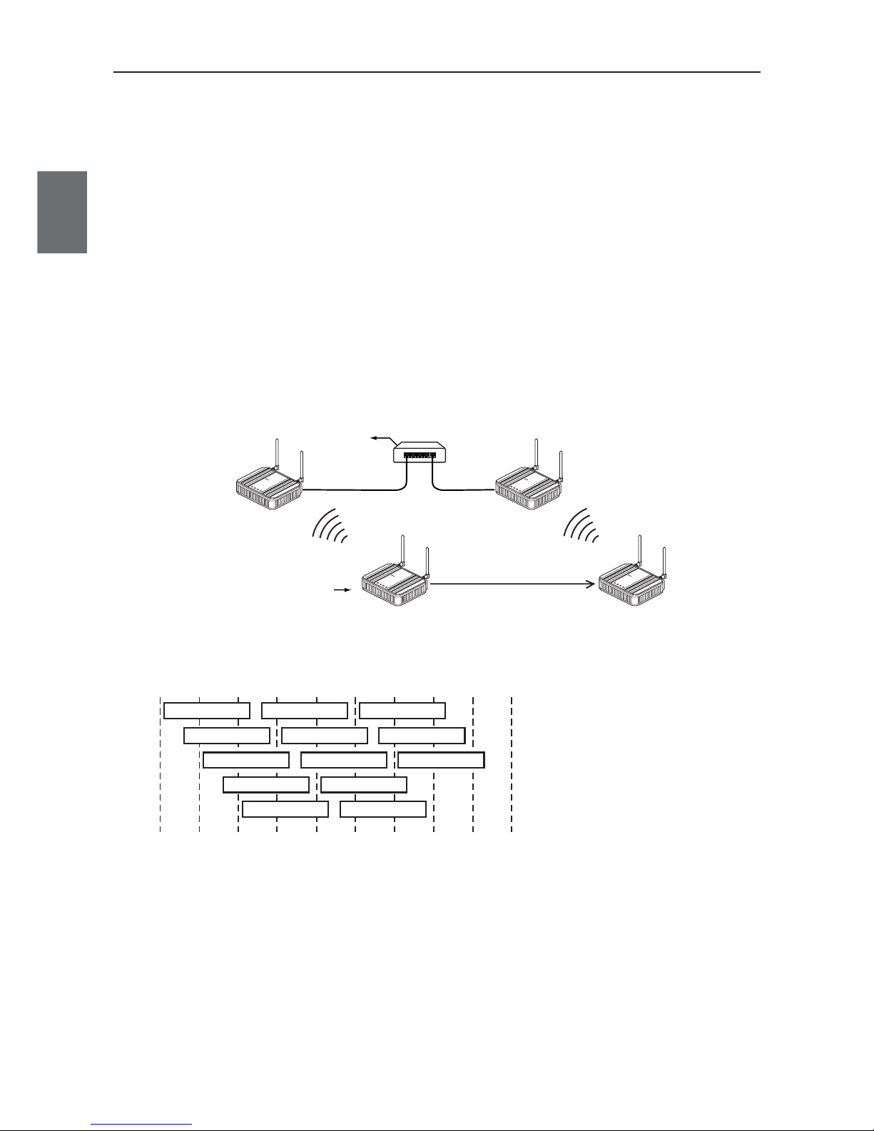
■
Relay Function
This function extends communication distance using other access point of AP-to-AP bridging as a wireless
repeater.
BSSID of respective access point must be registered for those that use AP-to-AP bridging.
Communication will be available between a distant access point and a client (slave) via a repeater.
* Up to 7 access points (including own unit) can be used for communication at the same time.
When one path is busy, other paths suspend communication. Because of this, all throughput is 1/6(1/ access number) by AP-to-AP
Bridging.
For the diagram of the maximum connection structure of communication AP-to-AP Bridging, see Ex 1 – 3 in “4-1 To Use AP-to-AP
Bridging” (P.4-2 and 4-3).
* All access points that use AP-to-AP bridging must be configured to use the same channel.
* For more information on AP-to-AP bridging, see "To Use AP-to-AP Bridging" (P.4-2).
Configuring the same SSID (3-3 Step 2. Configuring Wireless Network Name (SSID)(P.3-8)) allows detection of BSSID of the others,
making registration easier.
* If connection described below is made in addition to the example above, spanning tree function must be configured to avoid looping of
packets.(See P.1-5)
•A network has 3 or more wireless units using AP-to-AP bridging.
•Connecting access points (between A and B) using AP-to-AP bridging through a LAN cable
* AP-to-AP bridging is not available at the channel where DFS function is provided.
Connected AP is
switched to another
AP due to the
movement of CL.
192.168.0.10
BSS ID:00-00-0A-68-20-00
192.168.0.1
BSS ID:00-00-0A-68-20-01
192.168.0.2
AP-to-AP bridging
[802.11g:ch11]
[SSID:omronwe70wlan]
[802.11g:ch11]
L
A
N
M
O
D
E
P
O
W
E
R
W
I
R
E
L
E
S
S
W
E
7
0
A
P
F
A
W
IR
E
L
E
S
S
L
A
N
A
C
C
E
S
S
P
O
I
N
T
WE70-AP
L
A
N
M
O
D
E
P
O
W
E
R
W
I
R
E
L
E
S
S
W
E
7
0
A
P
F
A
W
IR
E
L
E
S
S
L
A
N
A
C
C
E
S
S
P
O
I
N
T
WE70-AP
WE70-CL
L
A
N
M
O
D
E
P
O
W
E
R
W
I
R
E
L
E
S
S
W
E
7
0
C
L
F
A
W
I
R
E
L
E
S
S
L
A
N
A
C
C
E
S
S
P
O
IN
T
L
A
N
M
O
D
E
P
O
W
E
R
W
I
R
E
L
E
S
S
W
E
7
0
C
L
F
A
W
I
R
E
L
E
S
S
L
A
N
A
C
C
E
S
S
P
O
IN
T
Page 30
Chapter 1. Overview
1-10
1
Overview
1-2. Components and Functions
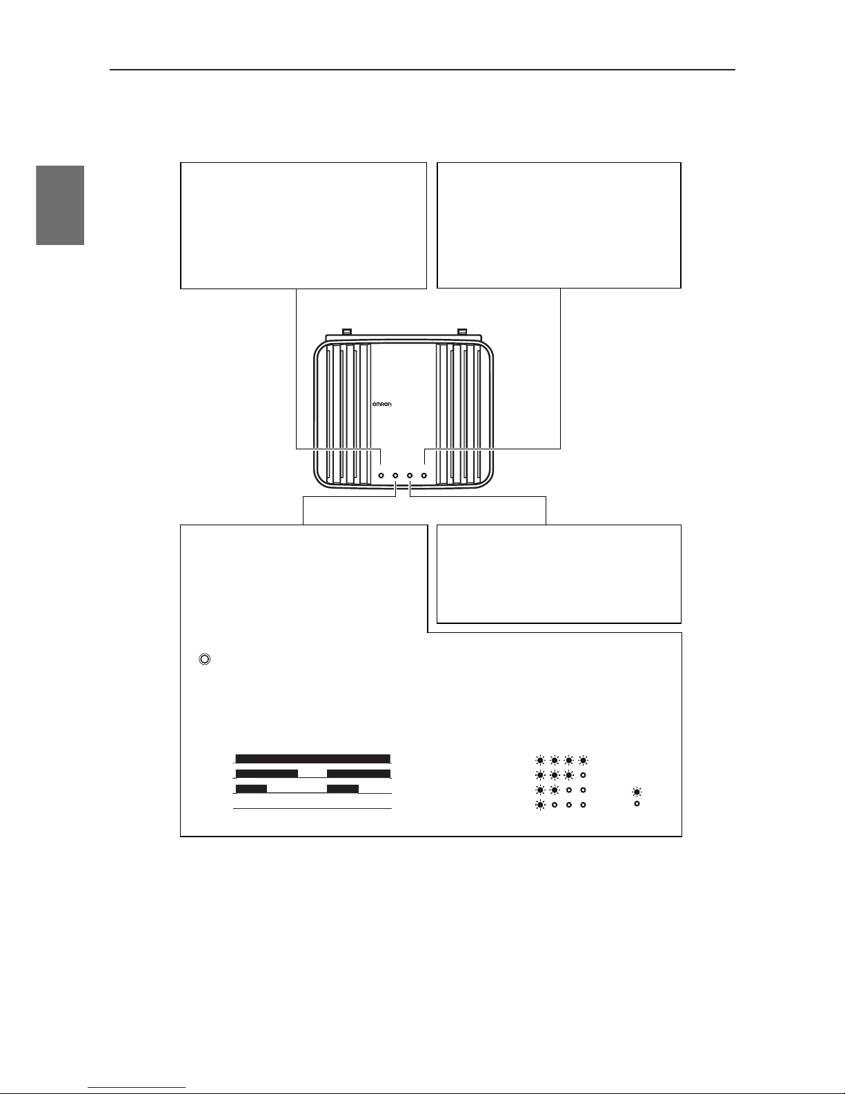
■
Top View
WE70-AP
WE70-AP
LANMODE
FA WIRELESS LAN ACCESS POINT
POWER WIRELESS
[LAN] Indicator (Orange)
Displays a status of the wired LAN.
On: LAN connection is normal
Off: LAN is not being connected
Flashing: Data is being transmitted
[MODE] Indicator (Orange)(WE70-AP)
Displays an operation mode of the wireless unit.
*1 [RSSI] indicator for
WE70-CL
[RSSI] Indicator (Orange)(WE70-CL)
Displays receiving electric field intensity
by flashing.
Flashing: Simultaneous flashing of [MODE] and
[POWER] indicates setup initialization.
Using 802.11a: On
Using 802.11b/g: Off
When the RSSI button on top of the unit is pressed,
receiving electric field intensity is displayed on
[RSSI], [LAN], and [WIRELESS] indicators in 4
levels. The [POWER] indicator flashes at the same
time.Indication returns to its original status when 10
minutes passes or the button is pressed again.
RSSI
LANRSSIPOWER WIRELESS
LEVEL4
LEVEL3
LEVEL2
LEVEL1
LEVEL4
LEVEL3
LEVEL2
LEVEL1
Off
Off:
On
On
On
On:
On
On
......Stable Level.................
......Usable Level......
......Unstable Level..........
......Unusable Level..........
<Flashing>
<On>
[WIRELESS] Indicator (Orange)
Displays a status of the wireless LAN.
On: Radio communication is being established
with the wireless unit.
Off: Absence of wireless LAN terminal which is
communicating with the wireless unit, or no radio communication has been made for more
than 5 minutes (10 seconds for WE70-CL).
[POWER] Indicator (Green)
Displays a power source status and a wireless
unit operation mode.
On: The wireless unit is turned on.
Flashing: Simultaneous flashing of [POWER] and
[MODE]
*1
indicates setup initialization.
Alternate flashing of [POWER] and
[MODE] indicates startup.
Page 31

1-11
Chapter 1. Overview
1
Overview
■
Rear View
[For Reference]
• Use a Crossed LAN cable for a connection between a wireless unit and a hub.
• The [LAN] port of a wireless unit does not support automatic detection of straight LAN cable or cross
LAN cable. Be careful for polarity to connect to a hub that does not support the automatic detection.
[LAN] indicator will not be lit if polarity is wrong.
• For 100BASE-TX communication, STP LAN cable of category 5 or higher must be used. If a cable with
lower category is used for the same LAN, total cable characteristics will be degraded to the lowest level
of such a cable.
WE70-AP
WE70-CL
ETHERNET
INIT
PUSH
RSSI
ETHERNET
INIT
+–
24V
+–
24V
<INIT> Button
Initializes setup.
* Use a pen tip to press.
"6-2. Restoring to Factory Shipment Status"
(See P.6-5)
DC Connector
Supplies 24VDC power.
RSSI Button
Switches receiving status
indication.
Flashing in 4 levels
[LAN] Port (RJ-45 x 1)
Connects a network device
such as a hub through a LAN
cable.
Antenna Connector
Used to connect accessory antennas.
* To ensure performance, always connect
both of 2 antennas.
Page 32

Chapter 1. Overview
1-12
1
Overview
Page 33

Chapter 2
Installation & Connection
This chapter describes
cautions for wireless unit installation and how to connect the unit set.
2-1. Installation ..............................................................................2-2
■
Installation Location ............................................................2-2
■
Installation Precautions ......................................................2-2
■
Precautions for Antenna Installation Location ....................2-3
■
Dimensions..........................................................................2-5
■
Installation Method ..............................................................2-5
2-2. Connection ..............................................................................2-7
■
Wiring Precautions ..............................................................2-7
■
Main Unit Power Wiring ......................................................2-7
■
LAN Cabling ........................................................................2-8
2-3. Connection Check ................................................................2-10
■
Checking Setup Screen Access ........................................2-10
Page 34

Chapter 2. Installation & Connection
2-2
2
Installation & Connection
2-1. Installation
Make sure that the radio wave conditions at the installation location are favorable before actually
installing the WE70 wireless unit.
■
Installation Location
Install this product as high as possible.
Do not install it to the following places:
• Where it is exposed to direct sunlight
• Where with extremely high humidity
• Near devices such as televisions, radios, and computers
• Near devices such as motor, drill, and welder
• Near strong magnets
• Near fluorescent lights
• Inside a metal panels or locations surrounded by metal or concrete
If WE70 is installed in a metal panel, be sure to mount the magnetic-base antenna outside the panel where
there are no obstacles.
■
Installation Precautions
●
Mounting Antenna
A set of 2 antennas function as diversity
and is good at multi-path, allowing
communication under stable radio wave
status.To install, hold the connection point
of antenna and turn the antenna clockwise.
Antennas can be bent to an angle ranging
from 0 to 90 degrees. They can be turned
right and left while being bent.
To uninstall, hold the connection point of
antenna and turn the antenna
counterclockwise.
* To ensure performance, always connect both of 2
antennas.
* If radio wave status is bad, change a direction or
an installation location of an antenna.
* Use antenna connector cover to dust preven-
tion.(See right)
●
Installing the magnet base antenna
and antenna extension cable
Use the connector cover when connecting
a cable.
●
Margin and Spacing
For heat release, ensure space between
a wireless unit and a control panel or
other equipment as shown in the right.
90
degrees
Antenna Connector Cover
(Accessory)
Put on a terminal area
Mounting Antenna Connector Cover
WE70-AP
L
A
N
M
O
D
E
P
O
W
E
R
W
IR
E
L
E
S
S
Turn clockwise
for installation.
Antenna x 2 (Accessory)
20mm or longer
20mm or longe
r
WE70-AP
LANMODE
FA WIRELESS LAN ACCESS POINT
POWERWIRELESS
Cable Bending Angle & Size
20
R
38
40
Using magnetic-base
Antenna WE70-AT001H &
WE70-CA5M
Antennas manufactured by other
manufacturer cannot be used
because of the conflict with Technical
Standard Conformity Certification.
Caution
Do not grasp or pull the antenna
itself which is mounted to the
wireless unit.
Otherwise it may be damaged.
Caution
Page 35

2-3
Chapter 2. Installation & Connection
2
Installation & Connection
●
Connecting the antenna extension cable (WE70-CA5M)
The cable length of the magnet base antenna is 2m. If longer length is required, use the antenna
extension cable (WE70-CA5M) 5m. Pay attention to attenuation of the cable when using the antenna
extension cable.
●
Precautions on Using Magnetic-base Antenna & Antenna extension cable
Using a magnetic-base antenna causes signal attenuation due to its cable, reducing communication range
compared with a standard pencil antenna.
Using Magnetic-base Antenna on Client
In an example below, receiving electric field strength decreases in the 5GHz band by up to 8
levels.Degree of decrease is larger in the 5GHz band that uses higher frequency than the 2.4GHz
band.To use a magnetic-base antenna, a communication range should take cable attenuation into account
for actual receiving electric field strength of a pencil antenna.
Using Magnetic-base Antenna on Access Point & Client
Using magnetic-base antennas & Antenna extension cable causes signal attenuation by up to 6 levels in
the 5GHz band, compared with a pencil antenna (accessory).If magnetic pedestal antennas are used for
both of an access point and a client in the 5GHz band, it is necessary to ensure additional 6 levels of
received field intensity to gain the same level of received field intensity as that of a pencil antenna.
Caution
• Holding or pulling an antenna while uninstalling may damage it.
• Always hold the base part for handling.
• Avoid cable twisting as long as possible.
• Before attaching it to a wireless unit, check if the plug and the jack are properly coupled, and tighten a ring nut.For
installation, turn the ring nut only while keeping a cable unturned.
• Take precautions so that a cable should not be damaged by a hole edge while putting it into the hole.
• Using a magnetic base antenna causes signal attenuation due to its cable, reducing communication range compared
with a standard pencil antenna.
■
Precautions for Antenna Installation Location
This wireless unit set uses very high radio frequencies of 2.4/5GHz.High frequency radio wave is progressive and reflective.
To ensure wireless performance, it is necessary to choose an appropriate location for antenna installation.
For co-polarization of each antenna, see "Appendices-3 Antenna".
L
A
N
M
O
D
E
P
O
W
E
R
W
IR
E
L
E
S
S
W
E
7
0
A
P
F
A
W
I
R
E
L
E
S
S
L
A
N
A
C
C
E
S
S
P
O
I
N
T
WE70-CL
LANRSSI
FA WIRELESS LAN ACCESS POINT
POWERWIRELESS
Magnetic-base Antenna (WE70-AT001H)
Cable loss attenuation in 5 GHz band: 0 (0)
+Antenna extension cable (WE70-CA5M)
Cable loss attenuation in 5 GHz band: 3 (2)
Attenuation figures
indicate receiving
electric field strength
Attenuation=8
Figures in ( ) are for 2.4 GHz:IEEE802.11b/g
WE70-AP
WE70-CL
WE70-CL
LANRSSI
FA WIRELESS LAN ACCESS POINT
POWER WIRELESS
WE70-AP
LANMODE
FA WIRELESS LAN ACCESS POINT
POWER WIRELESS
Cable loss in
5 GHz band
Attenuation A
Cable loss in
5 GHz band
Attenuation B
Figures in ( ) are for 2.4 GHz:IEEE802.11b/g
Attenuation figures indicate receiving electric field strength
Attenuation A+B = 0(0) Magnetic-base Antenna(WE70-AT001H)
6(4) Magnetic-base Antenna(WE70-AT001H)+Antenna extension cable(WE70-CA5M)
WE70-AP
WE70-CL
For receiving electric field strength, see "5-3. Setup Screen (WE70-CL)" (P.5-19).
Page 36

Chapter 2. Installation & Connection
2-4
2
Installation & Connection
(4) Install the Antennas with the same orientation
Install Antennas that are performing communications with the same orientation, as shown in the following
diagram. If they are installed at an angle of 90 degrees to each other, the possible communications
distance will be shortened.
(5) Do not subject the Antenna to shock
Do not install an antenna which it may be hit by other objects.Take preventive measures for installation in
such a place.Subjecting the Antenna to strong shock may cause either external or internal damage to the
Antenna. Internal damage that is not necessarily visible may prevent communications, such as broken wires.
L
A
N
M
O
D
E
POWE
R
W
I
R
E
LES
S
WE70-AP
F
A
W
IR
ELES
S
L
A
N
AC
C
E
S
S
POI
N
T
L
A
N
M
O
D
E
P
O
WE
R
WI
R
E
LE
S
S
WE70-AP
F
A
W
I
R
E
L
E
S
S
L
A
N
AC
C
ES
S
P
OI
N
T
L
A
N
M
O
D
E
P
O
WE
R
W
I
R
E
L
E
S
S
WE70-AP
F
A
W
I
R
E
L
E
S
S
L
A
N
AC
C
ES
S
P
OI
N
T
L
A
N
M
O
D
E
P
O
WE
R
WI
R
E
L
E
S
S
WE70-AP
F
A
W
I
R
E
L
E
S
S
L
A
N
AC
C
E
S
S
P
OI
N
T
If the Antennas are installed in locations with relatively high ceilings and a lot of open space, even if there
is no direct line of sight between the Antennas, if one of the Antennas is installed in a high location,
communications may still be possible via radio waves that are reflected off the ceiling.
(2) Install in as high location as possible
As mentioned in the preceding paragraph, if the Antennas are installed in high locations, since the space
surroundings the Antennas will be more open, there will be less influence from obstacles, and the radio
waves will propagate more easily.
.
(3) Do not put any obstacle (especially a metal object) near the Antennas
If there are obstacles near the Antennas (in particular, in the direction of radio wave propagation), the
radio waves may not be propagated due to the influence of the objects. Metal objects have the greatest
influence as they reflect radio waves, whereas glass and plastic objects allow the waves to pass through
and so have the least influence. Be sure to install Antennas at least 30 cm away from any obstables.
High Antenna Location
Obstacle
Obstacle
Obstacle
Radio Wave Energy
L
A
N
M
O
D
E
P
O
W
E
R
W
I
R
E
L
E
S
S
W
E
7
0
A
P
F
A
W
IR
EL
ES
S
L
AN
AC
C
ES
S
P
O
IN
T
Transmitting Antenna
Obstacle
Area not in a direct
line of sight from the
Antenna
Antenna that is
difficult for the
waves to reach
Antenna that
waves will reach
L
A
N
M
O
D
E
P
O
W
E
R
W
I
R
E
L
E
S
S
W
E
7
0
A
P
FA W
IR
E
L
E
SS
L
A
N A
CCE
SS
PO
INT
L
A
N
M
O
D
E
P
O
W
E
R
W
I
R
E
L
E
S
S
W
E
7
0
A
P
F
A
WIRE
LE
S
S LAN
A
CCE
SS
POIN
T
L
A
N
M
O
D
E
P
O
W
E
R
W
I
R
E
L
E
S
S
W
E
7
0
A
P
FA
WI
RE
LES
S
L
AN
ACC
ES
S
P
O
I
N
T
(1) Install antennas so that there is a direct line of sight between them
WE70 uses radio waves with a frequency of 2.4GHz and 5GHz, which are very high. High-frequency
waves, which exhibit strong rectilinear propagation and are reflected easily. For this reason, much
consideration is required for the Antenna installation location to achieve optimal wireless performance.
This is particularly important point for long distance communication over 50 to 60m.
Page 37

2-5
Chapter 2. Installation & Connection
2
Installation & Connection
■
Dimensions (Common with WE70-AP/CL)
■
Installation Method
●
Mounting Magnets
Mounting magnets allows
temporary installation and easy
move for setup and testing before
actual operation.
Mount magnets using screws as
shown in the right.
For WE70-CL Only
ETHERNET
INIT
PUSH
RSSI
+–
24V
WE70-AP
LANMODE
FA WIRELESS LAN ACCESS POINT
POWER WIRELESS
120 ± 1.0
34.5 ± 0.5
36
103 ± 1.0
22.6
107.6 ± 1.0
(Unit: mm)
128.5
231.5
Mounting screws for this wireless
unit must be tightened with torque of
4.4 to 5.3in. lb. (0.5 to 0.6N.m)
Tighten using screws at the mounting holes
Flat-head screw
(Accessory)
Mounting Hole Dimensions
(unit mm)
108 ± 0.1
116 ± 0.1
4 – M5
Screw Mounting
Bracket (Accessory)
Tapping Screw
(Accessory)
Magnet (Accessory)
Flat-head screw (Accessory)
Mounting screws for this wireless unit
must be tightened with torque of 4.4 to
5.3in. lb. (0.5 to 0.6N.m)
●
To Mount Using Mounting
Bracket
Attach the mounting bracket on
accessory magnets which are
installed on a wireless unit.
Installation on a control panel
requires screw hole drilling.
Installation with magnets cannot be used at the location with excessive vibration. Use the mounting bracket or DIN
rail adapter in that case.
Caution
Page 38

Chapter 2. Installation & Connection
2-6
2
Installation & Connection
●
To Mount on a DIN Rail
Do not install a product with a pencil-type antenna in a metal panel as it may result in degradation of radio
performance.To install this product in a panel, use and install a magnetic-base antenna outside the
panel.See "Options" of "Appendices", "Antenna" (P.Appendix-3).
Applicable Rail
There are 2 types of rails with a width
of 35mm, height of 7.5mm or 15mm.
(Conformance to DIN, EN, IEC, and
JIS C2812 standards)
Mounting DIN Rail Adapter
Model Rail Specification
WT30-FT001 TH35-7.5 Rail width 35mm and height 7.5mm
WT30-FT002 TH35-15 Rail width 35mm and height 15mm
Pull it to the right and lower it while pressing the spring.
Insert a spring
Hold the part A and insert the tip
A
27
7.5
0
-0.4
1 ± 0.04
1 ± 0.04
24
15
15
DIN rail length (unit mm)
Part A
35 ± 0.3
Less than 0.3
TH35-7.5 Details
of part A
TH35-7.5 Details
of part A
Mounting screws for this wireless
unit must be tightened with torque
of 4.4 to 5.3in. lb. (0.5 to 0.6N.m)
Mount it on the main unit and
clamp it using screws (M3).
<Mounting>
<Demounting>
DIN Rail
Hitch a tab on the top to the DIN rail
Pull the bottom side forwards
DIN Rail
Unhitch a tab from the DIN rail
Pull the lower part
Insert a flat-head screw driver
under the lower tab and pull downward
WE70-AP
LANMODE
FA WIRELESS LAN ACCESS POINT
POWER WIRELESS
Page 39

2-2. Connection
For connecting the antenna and the antenna extension cable, see “2-1 Installation” (P 2-1).
■
Wiring Precautions
• Signal lines and power lines must be separated to avoid influence of noise.
• Do not lay cables close to antennas.
• Wiring must be done while power is off.
• Use a pin terminal or a cable for connection as shown below.
A pin terminal must be clamped with an appropriate tool based on its size.The tip of a wire must be cut in the
same length as the pin terminal or 0.5mm longer.A whisker must not exist, and a pin terminal must not be
broken.
• Plug the pin terminal into the power terminal block to the end.Fix wiring close to its connector so that a
cable should not apply load to the connector due to its twisting or weight.
• A pin terminal must be unplugged while inserting a flat-head screw driver as shown below.
■
Main Unit Power Wiring
Power of the wireless unit is 24VDC.
A wireless unit requires 24VDC power supply.
Use a power source of 15W or higher, taking
inrush current on startup into account.
Omron's switching power supply is recommended.
See "Option" of "Appendix", "Power Supply" (P.Appendix-3).
And, it power is supplied from the battery supply via the DC-DC converter.
• This unit needs to be installed under local regulations.
• This unit is intended to be supplied by a "Listing Class 2" or "L.P.S." and rated from 24V, 250mA.
24V
W
E
70-A
P
F
A
W
IR
E
L
E
S
S
L
A
N
A
C
C
E
S
S
P
O
IN
T
L
A
N
M
O
D
E
P
O
W
E
R
W
IR
E
L
E
S
S
W
E
70-A
P
F
A
W
IR
E
L
E
S
S
L
A
N
A
C
C
E
S
S
P
O
IN
T
L
A
N
M
O
D
E
P
O
W
E
R
W
IR
E
L
E
S
S
Plugging
Unplugging
0 to 0.5 mm
Insufficient Stripping Length
Damage on Side
Whisker
Correct
Incorrect
Cable(AWG 26〜17)pin terminal
10 to11 mm
Stripping Length
(AWG 1 6〜12)Solid Wire(UL Listing)
(AWG 2 2〜14)Stranded Wire(JIS)
2-7
Chapter 2. Installation & Connection
2
Installation & Connection
Line Voltage 24VDC
Allowable Voltage Range 20.4 to 26.4VDC
Phoenix Contact Inc.*
Pin terminal AWG18 AI 0.75-10
Clamping Tool CRIMPFOX ZA3
Page 40

Chapter 2. Installation & Connection
2-8
2
Installation & Connection
■
LAN Cabling
LANMODEPOWER WIRELESS
Check if the indicator
is on after connection.
A Crossed LAN cable is required between a wireles
s
12345678
12345678
To LAN port
To 24VDC Power
Crossed
LAN cable
Straight
LAN cable
Uplink port
is not used
Ethernet
WE70-AP
xxxx
Connection Diagram
(Cross connected)
Make sure that you hear a
click sound when you insert
a cable.
ETHERNET
INIT
+–
24V
PC
Turn off power of a wireless unit and connected devices before cabling.
Caution
* A straight LAN cable can be used for direct connection of PLC or PC to a wireless unit for setup.
Use a crossed LAN cable for a connection between a wireless unit and a hub.
* STP LAN Cable must be used.
Page 41

2-9
Chapter 2. Installation & Connection
2
Installation & Connection
●
Using Switching Hub (1:N Connection)
Odd number times of cross connection are
required to connect between end nodes.
LAN Cable
Straight Wiring
UP LINK ports
are not used
Cross connection inside.
Ethernet
xxxx
PC
PLC
Ports other than UPLINK have no difference
such as master/slave or upper/lower (all other
ports other than UPLINK are equal)
●
Using WE70 (1:N Connection)
Straight
LAN cable
Straight
LAN cable
Straight
LAN cable
WE70-AP
WE70-CL
Wireless connection between a
WE70-AP and a WE70-CL corresponds
to cross connection.
LAN
MODE
POWER
WIRELESS
W
E
70-AP
FA
W
IR
E
LE
SS
L
AN
AC
C
E
S
S
P
O
IN
T
L
AN
MODE
POWER WIRELESS
WE70-CL
F
A
W
IR
E
L
E
S
S
L
A
N
A
C
C
E
S
S
P
O
I
N
T
L
AN
MODE
POWER WIRELESS
WE70-CL
F
A
W
IR
E
L
E
S
S
L
A
N
A
C
C
E
S
S
P
O
I
N
T
LAN
MODE
POW
ER WIR
ELESS
WE70-CL
F
A
W
I
R
E
L
E
S
S
L
A
N
A
C
C
E
S
S
P
O
I
N
T
IEEE802.11a/b/g wireless LAN can
"connect more than 1 client to 1
access point".
Page 42

Chapter 2. Installation & Connection
2-10
2
Installation & Connection
2-3. Connection Check
■
Checking Setup Screen Access
This section describes how to make access to a setup screen for a wireless unit via a WWW browser of a
wired computer on LAN.
* Use Microsoft Internet Explorer 6.0 or higher as the WWW browser of your PC.
* In this document Internet Explorer 6.0 is used.
* A screen shown below indicates a factory shipment status or all-initialized status of a wireless unit.
●
IP Address Setup
This section describes how to configure a fixed PC IP address (ex.: 192.168.0.100) on Windows XP.
IP addresses of a wireless unit set are "192.168.0.1" for an access point and "192.168.0.254" for a client
(slave).
<To Configure>
(
1) Start your PC.
(2) In the Logon screen, log on using administrator's user name.
(3) Select <Start>, [Control Panel].
(4) Click [Network and Internet Connections].
(5) Click [Network Connections].
Click
(6) Right-click on [Local Area Connection] icon with your Ethernet card
name, then select [Properties] from the context menu.
Right-Click
1.
Click
2.
Page 43

2-11
Chapter 2. Installation & Connection
2
Installation & Connection
(7) Check the box of "Internet Protocol (TCP/IP)" and click <Properties>.
Click
1.
Click
2.
(8) Select [Use the following IP address] radio button.Enter [IP
address](192.168.0.100) and [Subnet mask](255.255.255.0), then click
<OK>.(* Close a screen shown in Step (7))
Click
1.
Input IP address
2.
Click
3.
●
IP Address Assignment
An IP address consists of 2 fields; a network block and a host block.
Take a default IP address "192.168.0.254"(class C) of a wireless unit. "192.168.0." represents a network
block and the remaining "254" represents a host block.Network devices (e.g. PC) with the same "network
block" of IP addresses are identified as those on the same network.
A "host block" identifies each network device on the same network.
The followings must be taken into account for assignment of IP addresses:
• Assign the same "network block" for network devices that should be on the same network
• Do not assign the same "host block" for network devices on the same network
• Do not assign a network address (one that has "0" as its host block, in case of subnet mask of
"255.255.255.0")
• Do not assign a broadcast address (one that has "255" as its host block, in case of subnet mask of
"255.255.255.0")
Click after
setup by Step
(8).
Before changing an IP
address, record the
current value.
Page 44

Chapter 2. Installation & Connection
2-12
2
Installation & Connection
● WWW Browser (IE) Setup
Configuration must be made so that dial-up access should not be made when a WWW browser is started.
<To Configure>
(1) Select [Tool], [Internet Options], then select [Connections] tab.
(2) Select [Never dial a connection] and click <OK>.
Click
1.
Click
2.
●
Proxy Setup
Configuration must be made not to use a proxy server.
<To Configure>
(1) From the above screen, click [LAN Settings].
(2) Uncheck all boxes, then click <OK>.
Click
1.
Uncheck
1.
Click
2.
Page 45

2-13
Chapter 2. Installation & Connection
2
Installation & Connection
Screen of WE70-AP
●
Initiating Setup Screen
(1) Start a WWW browser.
(2) Enter the IP address specified for the wireless unit in the address bar of
the WWW browser.
Enter "http://192.168.0.1/" (factory shipment status) for WE70-AP and
"http://192.168.0.254/" (factory shipment status) for WE70-CL, and press
[Enter] key.
(3) In case of an access point, a user name input is admin and a password
input is requested. Press [Enter] key while leaving the password field
blank.Initial value (User name: admin, Password: Blank)
• A Basic Setup screen of Network Setup menu is displayed.
* To configure SSID and encryption of wireless LAN from PC connected
to a wired LAN, see sections "3-4. Configuring Encryption" (P.3-12) to
"3-5. Communicating with PLC" (P.3-21).
* For more information on the screen, see "5-1. Setup Screen &
Functions" (P.5-2).
Setup Screen
(1) Enter http://192.168.0.1/
(2) Press [Enter] key.
Screen of WE70-CL
(1) Enter http://192.168.0.254/
(2) Press [Enter] key.
Page 46

Chapter 2. Installation & Connection
2-14
2
Installation & Connection
●
Access Point Communication Speed
WE70-AP works as an access point in IEEE802.11a /b/g standards.
If clients (slaves) of IEEE802.11b and IEEE802.11g make
access to an access point at the same time, communication
speed may remarkably decrease.
Although up to 63 clients (slaves) can be used for the same
wireless LAN standard* at the same time, it is
recommended that number of clients should be limited to
10 or less.
In an environment where clients (slaves) of IEEE802.11b
and IEEE802.11g exist, use 11g protection mode.(See "4-8.
Limiting IEEE802.11b Communication" (P.4-21))
*
An IEEE802.11b client (slave) is assumed to be included in access point "IEEE802.11g" standard.
L
A
N
M
O
D
E
P
O
W
E
R
W
I
R
E
L
E
S
S
WE70-CL
F
A
W
I
R
E
L
E
S
S
L
A
N
A
C
C
E
S
S
P
O
IN
T
Wireless LAN
WE70-AP
Page 47

This chapter describes
how to establish communication between an access point and a client
(slave) as well as a PLC using PC.
3-1. Setup Workflow ......................................................................3-2
3-2. Opening Setup Screen ............................................................3-3
Step 1. PC (Wired LAN) Setup................................................3-3
Step 2. Connecting..................................................................3-3
Step 3. Checking Setup Screen Access..................................3-4
Step 4. Monitoring Wireless Communication Status ..............3-5
■ To display the setup screen in Japanese ............................3-6
3-3. Configuring IP Address/SSID/Channel....................................3-7
Step 1. IP Address Setup........................................................3-7
Step 2. Configuring Wireless Network Name (SSID) ..............3-8
Step 3. Configuring Channel ..................................................3-9
Step 4. Checking Communication ........................................3-11
Step 5. Other Setups ............................................................3-11
3-4. Configuring Encryption ..........................................................3-12
■ To Enter Encryption Key Using ASCII Characters ............3-12
■ Entering Encryption Key ....................................................3-13
■ Setup Example of Encryption Key ....................................3-14
■ To Enter Encryption Key Using hexadecimal number ......3-15
■
Conversion Table from ASCII Character to hexadecimal number
..3-16
■ To Generate Encryption Key Using Key Generator ..........3-17
■ To Configure TKIP/AES/WOC KEY Encryption ................3-18
3-5. Communicating with PLC ......................................................3-20
Step 1. Preparing PLC & PC ................................................3-20
Step 2. MAC Address Setup ................................................3-21
Step 3. PLC Setup ................................................................3-21
Step 4. Checking Communication with PLC..........................3-22
■ Precautions for Communication with PLC ........................3-22
Chapter 3
Basic Setup
Page 48

Chapter 3 Basic Setup
3-2
3-1. Setup Workflow
Read steps described below to introduce a wireless unit set.
Steps are compiled so that basic setup can be made in their order.
Numbers indicated in the right of these steps indicate pages to refer to in this document.
Step 1
Step 2
3-3. Configuring IP Address/SSID/Channel 3-7
Step 3
3-4. Configuring Encryption 3-12
3-5. Communicating with PLC 3-20
Step 4
3
Basic Setup
3-2. Opening Setup Screen 3-2
Page 49

3-3
Chapter 3 Basic Setup
3
Basic Setup
3-2. Opening Setup Screen
This section describes steps from opening a setup screen for an access point and a client (slave) to checking
communication.
Step 1. PC (Wired LAN) Setup
Configure an IP address through Chapter 2-3. Connection Check, IP Address Setup (P.2-10).
Step 2. Connecting
(1) Connect an access point and PC using a LAN cable.
Always use a straight cable.
(2) Connect power cables of an access point and a client (slave).
(3) Turn their power on and check indication of each POWER indicator as
shown below.
Check the LAN indicator of the access point because it is connected to
PC.
To 24VDC Power
To 24VDC Power
Straight LAN Cable
WE70-AP
WE70-CL
LANMODEPOWERWIRELESS
Checkiftheindicator
isonafterconnection.
LANRSSIPOWERWIRELESS
Checkiftheindicator
isonafterconnection.
ETHERNET
INIT
PUSH
RSSI
ETHERNET
INIT
+–
24V
+–
24V
Check the light is ON.
LANMODEPOWERWIRELESS
Check the light is ON.
L
A
N
M
O
D
E
P
O
W
E
R
W
I
R
E
L
E
S
S
WE70-AP
F
A
W
I
R
E
L
E
S
S
L
A
N
A
C
C
E
S
S
P
O
I
N
T
Access point
WE70-AP
L
A
N
M
O
D
E
P
O
W
E
R
W
IR
E
L
E
S
S
WE70-CL
F
A
W
I
R
E
L
E
S
S
L
A
N
A
C
C
E
S
S
P
O
I
N
T
Client (Slave)
WE70-CL
LANRSSIPOWERWIRELESS
(4) Check if each WIRELESS indicator of the access point and the client
(slave) is on in several seconds (about 8 seconds).Communication will be
started as they have the same SSID and channel in their factory
shipment status.
Page 50

Chapter 3 Basic Setup
3-4
3
Basic Setup
For WE70-AP
(1) Enter the IP address specified for the access point in the address bar of
the WWW browser.
Enter "http://192.168.0.1/" (factory shipment status) and press [Enter]
key.Enter [admin] to user-name. and press [Enter] key ignoring a
password request.
* A screen shown below indicates a factory shipment status or all-initialized status of a wireless unit.
Step 3. Checking Setup Screen Access
This section describes procedures for setup screen access of a client (slave) through a WWW browser.
<Initiating Setup Screen>
(1) Start a WWW browser.
* In this document Internet Explorer 6.0 is used.
(2) Enter the IP address specified for the client (slave) in the address bar of
the WWW browser.
Enter "http://192.168.0.254/" (factory shipment status) and press [Enter] key.
• A screen in Settings menu is first displayed.
* A screen shown below indicates a factory shipment status or all-initialized status of a wireless unit.
1. Enter http://192.168.0.254/
2. Press [Enter] key.
Specifying the configured IP address
(factory shipment setup:
192.168.0.254) in this field allows
access.
1. Enter http://192.168.0.1/
2. Press [Enter] key.
Specifying the configured IP address
(factory shipment setup: 192.168.0.1)
in this field allows access.
Page 51

3-5
Chapter 3 Basic Setup
3
Basic Setup
Click
①
Step 4. Monitoring Wireless Communication Status
If the client is under communication with the access point, the screen displays "Online ■■■".
If not, "Communication Unavailable" is displayed.Verify a channel through which communication should be
made.
* "Communication Unavailable" may be displayed until the WWW browser screen is updated in a case such as after setup change.
(1) To monitor detailed status, click <Radio status>.
• An independent screen displays Wireless communication status
information.
* Information on the independent screen is updated every 0.5 seconds, while continuous
monitoring increases network load.Close the screen after verification.
If the client has different SSID
and/or encryption setup from the
access point, "Communication
Unavailable" is displayed.
It is same for 4-level indication of
the client (slave) RSSI indicator.
Page 52

Chapter 3 Basic Setup
3-6
3
Basic Setup
[For Reference]
• Some wireless LAN devices may use a name ESS ID for a wireless network name, which is same as SSID.
• To check access to an access point, specify LAN-end IP address (such as 192.168.0.1) of the access point based on a procedure
in 2-3. Connection Check, IP Address Setup (P.2-10).
A setup screen of the access point is displayed.
* In case of an access point, a password input is requested.
(1) <Radio Status> Button ......... Radio wave intensity that an access point can receive is displayed
in the right of this button. If the client has different SSID and/or encryption
setup from the access point, "Communication Unavailable" is displayed.
Radio wave intensity is displayed in 4 levels as shown below.
Levels may differ depending on a communication type.
● Level: □□□ ■□□ ■■□ ■■■
0-8 9-14 15-20 21 or higher (in case of 802.11a)
0-13 14-19 20-25 26 or higher (in case of 802.11b/g)
Clicking <Radio status> allows monitoring of statuses of radio
communication such as channels and communication speed in the
[Wireless communication status].
When the power of the wireless unit is turned ON again after turning OFF, the setup screen will be
displayed in English (Default Setting).
■ To display the setup screen in Japanese.
Click
1.
Page 53

3-3. Configuring IP Address/SSID/Channel
This section describes steps from changing setup values of an access point and a client (slave) to
establishing communication.
Step 1. IP Address Setup
This section describes how to change IP address setup.
<To Configure>
(1) Open a setup screen of the wireless unit (see Chapter 2-3. Connection
Check, Opening Setup Screen (P.2-13)) and click Network Settings
menu.
(2) Change the LAN-end IP address to "192.168.0.2".
(3) Click <Apply and restart>.
After restart AP or CL, input registered IP adress to URL of IE, and open
the setup screen.
3-7
Chapter 3 Basic Setup
3
Basic Setup
Screen of WE70-CL
Screen of WE70-AP
Click
1.
Enter the IP address
2.
Click
1.
Enter the IP address
2.
Click
3.
Click
3.
Page 54

Chapter 3 Basic Setup
3-8
3
Basic Setup
Screen of WE70-CL
Click
1.
Enter
2.
Click
3.
Step 2. Configuring Wireless Network Name (SSID)
This section describes how to change a wireless network name (SSID).
● Wireless Network Name (SSID)
An access point and a client (slaves) have SSID (or ESS ID) as wireless network names to identify each
other for communication.
If more than one wireless routers or access points exist in one wireless communication zone, cross talk
with other wireless network group can be prevented by identification using different SSID (wireless
network name) for each wireless network group.
A wireless LAN terminal with a SSID different from a wireless unit cannot communicate.
* If ANY-connection refusal setup is being disabled for an access point, and if a SSID of a client (slave) is blank, the client (slave) can
communicate with the access point regardless of access point SSID setup.
<To Configure>
(1) Open a setup screen of the wireless unit (see Chapter 2-3. Connection
Check, Opening Setup Screen (P.2-13)) and click Wireless settings
menu.
• A Wireless settings screen is displayed.
(2) Enter the desired alphanumeric characters in SSID (within 31 characters)
with the attention for capitalization.
(Initial value: omronwe70wlan)
(3) Click <Apply and restart>.
* If a wireless LAN terminal is used for setup, switch the connection to the SSID configured
here.
Screen of WE70-AP
Click
1.
Enter
2.
Click
3.
Page 55

3-9
Chapter 3 Basic Setup
3
Basic Setup
SSID: Illegal access using "blank"
* If ANY-connection refusal setup is being disabled, and if a SSID (or ESS ID) of a client (slave) is blank, the client (slave) can
communicate with the access point regardless of access point SSID setup.
* To refuse access, enable ANY-connection refusal from Wireless Setup > Detailed Communication Setup of the access point.The
wireless unit's SSID will not appear on a standard wireless network connection screen of Windows XP then.
Step 3. Configuring Channel
This section describes how to change a wireless channel.
Wireless channel setup must be made on an access point.A client (slave) has no such setup, but it must be
configured as the same communication type as that of the access point.The channel setup is IEEE802.11a
and 36CH (5180MHz) for factory shipment status.
● Channel (frequency)
Following 24 channels can be used in 5GHz.
Following 13 channels can be used in 2.4GHz. (Except 12CH and 13CH in United States)
Channel
36CH
40CH
44CH
48CH
Frequency (MHz)
5180
5200
5220
5240
Channel
52CH
56CH
60CH
64CH
Frequency (MHz)
5260
5280
5300
5320
This is an example for connecting a PC wired LAN to a client (slave) and setup must be made from an
access point to communicate.To change the setup from a client (slave), it is necessary to switch the LAN
cable to the access point end.In this case, the setup screen may not be available due to specification,
which can be solved by entering a command "arp -d" at command prompt of PC.
↑
Space
Frequency (MHz)
2437
2442
2447
2452
2457
Channel
1CH
2CH
3CH
4CH
5CH
Frequency (MHz)
2412
2417
2422
2427
2432
Channel
6CH
7CH
8CH
9CH
10CH
Frequency (MHz)
2462
2467
2472
Channel
11CH
12CH
13CH
Channel
100CH
104CH
108CH
112CH
116CH
120CH
Frequency (MHz)
5500
5520
5540
5560
5580
5600
Channel
124CH
128CH
132CH
136CH
140CH
Frequency (MHz)
5620
5640
5660
5680
5700
Channel
149CH
153CH
157CH
161CH
165CH
Frequency (MHz)
5745
5765
5785
5805
5825
Except China and Japan United States and China
Except China
Page 56

Chapter 3 Basic Setup
3-10
3
Basic Setup
● Client (Slave) Setup
(1) Open a setup screen of the client (slave) (see Chapter 2-3. Checking
Connection, Opening Setup Screen (P.2-13)) and click Settings menu.
• A Settings screen is displayed.
(2) Select a communication method.
Example 802.11a
(3) Click <Apply and restart>.
• Communication becomes available through IEEE802.11a standard with
an access point.
● Access point setup
(1) Open a setup screen of the access point (see Chapter 2-3. Checking
Connection, Opening Setup Screen (P.2-13)) and click Wireless settings
menu.
• A Wireless settings screen is displayed.
(2) Select a channel.
Example: 36CH
(3) Click <Apply and restart>.
• Communication becomes available through IEEE802.11a standard with
a client (slave).
Click
1.
Select
2.
Click
3.
Click
1.
Select
2.
Click
3.
Verify that communication method
802.11a checkbox is on.Both
checkbox cannot be unchecked.
Page 57

3-11
Chapter 3 Basic Setup
3
Basic Setup
[DFS Function]
DFS function can be enabled only when an IEEE802.11a (52CH-64CH, 100CH-140CH) standard channel is set in Channel field of
Communication setting. If DFS function is being enabled, detection of interfering radio waves such as a weather radar automatically
changes the channel to a non-interfering IEEE802.11a standard wireless channel.
If a selected channel on startup is DFS, the [WIRELESS] indicator of a wireless unit flashes (for about 1 minute) and wireless access
is inhibited before restart of the wireless unit is completed.
Any response to a client stops and access to the unit is inhibited as well.
* DFS function will not be activated if the channel is changed to non-interfering IEEE802.11a (52CH-64CH, 100CH-140CH) standard one.
Caution
The Radio Law prohibits outdoor use of wireless LAN in IEEE802.11a standard (5GHz band).
Step 4. Checking Communication
Verify that PC connected to a client (slave) can connect to an access point.
<To Verify>
Check if the [WIRELESS] indicator is on.
* If the indicator is not on as shown in the right, communication is not
being established with an access point.
If the [WIRELESS] indicator does not turn on, check wireless LAN
setup of the access point and wireless unit set to be used and
network setup of PC, then restart them.
● To monitor radio status
(1) Open a setup screen of the wireless unit (see Chapter 2-3. Connection
Check (P.2-13)).
• The screen displays "Online ■■■".
* "Communication Unavailable" may be displayed until the WWW browser screen is
updated in a case such as after setup change.
(2) To monitor detailed status, click <Radio status>.
• An independent screen displays Wireless communication status
information.
* Information on the independent screen is updated every 0.5 seconds, while continuous
monitoring increases network load.Close the screen after verification.
LANRSSIPOWER WIRELESS
[On]
[Check if On]
WE70-CL
(Top View)
[For Reference]
• To check access to an access point, specify LAN-end IP address (such as 192.168.0.1) of the access point based on a procedure
Checking Connection, Opening Setup Screen (P.2-13).
• A setup screen of the access point is displayed.
* If access is controlled by a password, a message is displayed that requires password input.
Click
Step 5. Other Setups
For details of setup, see Chapter 5 Setup Menu.
If the client has different SSID
and/or encryption setup from the
access point, "Offline" is displayed.
Page 58

Enter is
described in the
next page.
Chapter 3 Basic Setup
3-12
3
Basic Setup
3-4. Configuring Encryption
WEP (RC4)/OCB AES encryption key setup can be configured by directly entering hexadecimal number or
ASCII characters in the WEP key text box or entering any alphanumeric characters or symbols in the Key
generator text box.The key generator automatically generates 4 encryption keys, one of which to be used
can be specified in the Key index.
* For encryption setup of TKIP, AES, and WOC KEY, see P.3-18.
■ To Enter Encryption Key Using ASCII Characters
Suppose following conditions to configure.
◎ Encryption method: WEP RC4, 128 (104) bits
◎ Key index: 1 (Factory Shipment Setting)
◎ Input Mode: ASCII character 13 character, hexadecimal number.
* Some wireless LAN devices may use names authentication mode and key ID, which are same as network authentication and key
index.
<To Configure>
The same setup must be applied to a client (slave) for communication.
(1) Open a setup screen of the access point (see Chapter 2-3. Connection
Check, Opening Setup Screen (P.2-13)) and click Wireless setting menu
> Security settings.
• A Security setting screen is displayed.
(2) Set Encryption method as WEP RC4 128 (104).
* If None (Factory Shipment Setting) is set, data will not be encrypted.
(3) In Input mode field of WEP key, click ASCII character 13 character radio
button.
Select
5.
Select
3.
Click
2.
Click
1.
Check that
configuration is
same as factory
shipment setting.
[Key Index Setup]
(Excluding Windows XP with Service Pack Applied)
A range of Key index (key IDs) is from 1 to 4 for Omron's wireless devices, while that for standard wireless network connection in
Windows XP is from 0 to 3.
Selecting "1" for a wireless unit is same as specifying "0" in Key index (advanced) in Windows XP.
Click
4.
Screen of WE70-AP
Click
6.
Page 59

3-13
Chapter 3 Basic Setup
3
Basic Setup
■ Entering Encryption Key
Number of encryption key digits depends on encryption method and input mode setting:
[Wireless LAN standard: IEEE802.11a /b/g]
Open
System
Input Mode
(HEX.)
ASCII
Character
WEP RC4, 64 (40) bits
WEP RC4, 128 (104) bits
Encryption method
10 digits 5 characters
26 digits 13 characters
Network
Authentication
Shared
Key
WEP RC4, 152 (128) bits
OCB AES, 128 (128) bits
32 digits 16 characters
32 digits 16 characters
* Number of digits available for input is indicated in ( ).
(4) Enter WEP key in text boxes from 1 to 4 of Key Index using ASCII
characters.(Example: OMRONWIRELESS)
* A WEP key must be configured as the same for communication in a text box of the same
number even if key indexes are different for those that communicate.
(5) Click <Apply and restart>.
• Setup is now being enabled.
Enter5.
This is
described in the
previous page.
Click
6.
Check that ASCII
Characters is
selected.
Page 60

Chapter 3 Basic Setup
3-14
3
Basic Setup
■ Setup Example of Encryption Key
This section describes how to configure encryption keys for an access point and a client (slave) by directly
entering hexadecimal number (26 digits) in case of RC4, 128 (104) bits.。
[Ex.] Enter "48-6f-74-73-70-6f-74-41-63-63-65-73-73" and "57-41-56-45-4d-41-53-54-45-52-4c-41-4e" to
key IDs 2 and 3 as shown below.
◎ WEP key values in key index 2 are same and communication is available.
WE70-AP End WE70-CL End
◎ WEP key values in key indexes 2 and 3 are different and communication is unavailable.
WE70-AP End WE70-CL End
◎ WEP key values in key indexes 2 and 3 are same and communication is available.
WE70-AP End WE70-CL End
Page 61

3-15
Chapter 3 Basic Setup
3
Basic Setup
■ To Enter Encryption Key Using hexadecimal number
Suppose following conditions to configure.
◎ Encryption Method: WEP RC4, 128 (104) bits
◎ Key Index: 1 (Factory Shipment Setting)
◎ Input Mode: Hexadecimal number (Factory Shipment Setting)
* Some wireless LAN devices may use names authentication mode and key ID, which are same as network authentication and key
index.
<To Configure>
The same setup must be applied to a client (slave) for communication.
(1) Open a setup screen of the access point (see Chapter 2-3. Connection
Check, Opening Setup Screen (P.2-13)) and click Wireless setting menu
> Security settings.
• A Security settings screen is displayed.
(2) Set Encryption method as WEP RC4 128 (104).
* If None (Factory Shipment Setting) is set, data will not be encrypted.
Select
3.
Click
1.
Enter
4.
Click
2.
This is
described in
the next page.
Enter
4.
Click
5.
Page 62

Chapter 3 Basic Setup
3-16
3
Basic Setup
ASCII
Character
Hex.
(3) Enter WEP key in text boxes from 1 to 4 of Key index using hexadecimal
numbers.
(Input Example 1: EF-04-9D-48-67-35-8B-80-45-94-FD-99-76)
(Input Example 2: EF049D4867358B804594FD9976)
* Results are the same for either examples.
* Communication is available when the same WEP key is set in a text box of the same
number even if key indexes are different from a client (slave).
(4) Click <Apply and restart>.
• Setup is now being enabled.
■ Conversion Table from ASCII Character to hexadecimal number
If your PC supporting wireless LAN does not support both modes, use the following conversion table to
specify a key to set.
[Ex.] "4f4d524f4e574952454c455353" (26 digits) in hexadecimal number is "OMRONWIRELESS" (13
characters) ASCII characters.
ASCII
Character
Hex.
! #$%&( ) *+,-./
21 22 23 24 25 26 27 28 29 2a 2b 2c 2d 2e 2f
0123456789 : ;<=>?
30 31 32 33 34 35 36 37 38 39 3a 3b 3c 3d 3e 3f
@A B C D E FGH I J KLMNO
40 41 42 43 44 45 46 47 48 49 4a 4b 4c 4d 4e 4f
PQRSTUVWXYZ[ \ ] ^_
50 51 52 53 54 55 56 57 58 59 5a 5b 5c 5d 5e 5f
`abcdefghi jklmno
60 61 62 63 64 65 66 67 68 69 6a 6b 6c 6d 6e 6f
pqr s t uvwxyz {│ }~
70 71 72 73 74 75 76 77 78 79 7a 7b 7c 7d 7e
ASCII
Character
Hex.
ASCII
Character
Hex.
ASCII
Character
Hex.
ASCII
Character
Hex.
Check that
Hexadecimal
number is selected.
Enter
4.
This is
described in
the previous
page.
Click
5.
Page 63

3-17
Chapter 3 Basic Setup
3
Basic Setup
■ To Generate Encryption Key Using Key Generator
This function can be used to set "Hexadecimal number" (factory shipment setting) to Input Mode field of
WEP Key.
* Entering any character string into the key generator automatically generates encryption keys in WEP Key text boxes.
* The key generator is incompatible with other manufacturers' products than Omron's.
Suppose following conditions to configure.
◎ Encryption method: WEP RC4, 128 (104) bits
◎ Key generator: OMRON
◎ Input Mode: Hexadecimal number (Factory Shipment Setting) * ASCII characters cannot be used.
* Some wireless LAN devices may use names authentication mode, which is same as network authentication.
<To Configure>
(1) Open a setup screen of the wireless unit (see Chapter 2-3. Connection
Check, Opening Setup Screen (P.2-13)) and click Wireless settings menu
> Security settings.
• An Encryption method screen is displayed.
(2) Set Encryption method as WEP RC4 128 (104).
* If None (Factory Shipment Setting) is set, encryption security is
disabled.
(3) Enter an alphanumeric numbers or symbols (within 31 characters) in Key
generator field.
(4) Click <Apply and restart>.
Click
2.
Click
1.
Select
3.
Check that
configuration is
same as factory
shipment setting.
Enter
4.
Check
Click
5.
Page 64

Chapter 3 Basic Setup
3-18
3
Basic Setup
■ To Configure TKIP/AES/WOC KEY Encryption
TKIP and AES encryption key setup can be configured by entering 64-digit hexadecimal number or 8
to 63 ASCII characters.For WOC KEY, only 8 to 63 alphanumeric characters can be used, while 64digit hexadecimal number cannot.
* For encryption setup for WEP (RC4)/OCB AES, see Chapter 3-4. Configuring Encryption (P.3-12).
Suppose following conditions to configure.
◎ Encryption method: TKIP
◎ PSK (Pre-Shared Key): OMRONWE70 (Use 8 to 63 ASCII characters)
<To Configure>
The same setup must be applied to a client (slave) for communication.
(1) Open a setup screen of the wireless unit (see Chapter 2-3. Connection
Check, Opening Setup Screen (P.2-13)) and click Wireless settings menu
> Security settings.
(2) Set Encryption method as TKIP.
* If None (Factory Shipment Setting) is set, data will not be encrypted.
(3) Enter OMRONWE70a in PSK (Pre-Shared Key).
(4) Click <Apply and restart>.Setup is now being enabled.
Click
2.
Click
1.
Select
3.
Enter
4.
Use either of:
• Alphanumeric: 8 to 63
characters
• Hex.: 64 digits
Click
5.
Page 65

3-19
Chapter 3 Basic Setup
3
Basic Setup
<Wireless LAN Terminal End: Connection Example for Windows XP (Service Pack 1)>
<Wireless LAN Terminal End: Connection Example for Windows XP (Service Pack 2)>
Example:
omronwe70a
(3) Click
(2) Enter a pre-shared
key
Example: omronwe70a
(1) Click
Applying Windows XP
(Service Pack 2) allows use
of WPA encrypted
authentication type in a
wireless LAN terminal.
(4) Click
(3) Enter
(5) Check
omronwe70wlan
(1) Click
(2) Click
Applying a certain update
program to Windows XP
(Service Pack 1) allows use of
TKIP and AES encrypted
authentication types in a
wireless LAN terminal.
SSID:
omronwe70wlan is
displayed on an
available wireless
network.
Page 66

Chapter 3 Basic Setup
3-20
3
Basic Setup
3-5. Communicating with PLC
This section describes how to set communication between an access point (WE70-AP) and a client (WE70CL).A PLC + Ethernet unit must be connected to an access point using a LAN cable.PC with Ethernet card
must be connected to a client (WE70-CL).
Step 1. Preparing PLC & PC
PLC is connected to Access point using straight LAN cable.
L
A
N
M
O
D
E
P
O
W
E
R
W
IR
E
L
E
SS
W
E
7
0
A
P
F
A
W
I
R
E
L
E
S
S
L
A
N
A
C
C
E
S
S
P
O
I
N
T
Access Point
WE70-AP
Straight LAN cable
A client (slave) can be configured by direct connection of a LAN cable or wireless connection by entering
"192.168.0.254" (factory shipment setting) to PC connected to an access point.
To connect a PLC to an Ethernet network, 100BASE-TX type Ethernet unit CS1W-ETN21 or CJ1W-ETN21
is required.
LAN
MO
DE
POW
ER
WIRELES
S
W
E
7
0
C
L
F
A
W
I
R
E
L
E
S
S
L
A
N
A
C
C
E
S
S
P
O
I
N
T
Client
WE70-CL
Straight LAN cable
PLC + Ethernet unit
Network Device
Description
CS series Ethernet unit
(CS1W-ETN21)
CJ series Ethernet unit
(CJ1W-ETN21)
A communication unit to connect a CS series or
CJ series PLC to a 100BASE-TX type Ethernet
network.
LAN Cable
A LAN cable with RJ45 modular connectors on
both ends,used to connect a 100BASE-TX type
Ethernet unit and an access point.
An STP (shielded twisted pair) cable of category
3, 4, 5, or 5e must be used.
Page 67

Step 2. MAC Address Setup
To attach PLC connected to WE70-CL to network, a client (slave) needs a setup as follows. Specifying a
MAC address (Ethernet address) of PLC's Ethernet unit to Terminal MAC Address field for WE70-CL.
Ex. For Ethernet unit CJ1W-ETN21, Ethernet address is indicated at the right side.
Step 3. PLC Setup
To connect a PLC to a network, Ethernet unit's IP address must be configured.A unique IP address must be
allocated for each communication node,using either of the followings:
1. Specifying with a default IP address
A rotary SW in the Ethernet unit can specify a FINS node address (1 to 254), which is used as a
host block of the IP address. A FINS node address and an IP address to be specified for an
Ethernet unit have the following relationship:
192.168.250.FINS_Node_Address
That is, specifying a node number 10 to a network of 192.168.250.* sets an IP address of
192.168.250.10 by default.
2. Specifying by Unit Setup of CX-Programmer
From I/O Table window of online CX-Programmer, select an Ethernet unit and specify an IP
address from Unit Setup.
3. Specifying by CPU advanced function unit assignment DM area
Under a status of an IP address unconfigured for Unit Setup, specify an IP address to IP
Address Display/Setup Area of CPU advanced function unit assignment DM area.
By default, IP addresses of an access point and a client are:
Access Point (WE70-AP): 192.168.0.1
Client (WE70-CL): 192.168.0.254
For details, see CS1W-ETN21/CJ1W-ETN21 Ethernet Units Construction of Networks Operation
Manual(W420-E1), Section 5-2. IP Address in FINS Communications.
CJ1W-ETN21
ETHERNET UNIT
Ethernet Address
Lot No.
OMRON Corporation
MADE IN JAPAN
MAC Address (12 digits)
3-21
Chapter 3 Basic Setup
3
Basic Setup
LAN
MO
DE
P
OW
E
R
WIR
E
L
ESS
WE70-CL
FA
W
IR
EL
E
SS
L
A
N
A
C
C
E
S
S
P
O
I
NT
L
AN
M
OD
E
PO
WE
R
WI
R
EL
ESS
WE70-CL
F
A
W
I
R
EL
E
S
S
L
A
N
A
C
C
E
S
S
P
O
IN
T
MAC Address
Access Point
WE70-AP
Client(Slave)
WE70-CL
Caution
Only 1 model connected to WE70-CL can be registered to Terminal MAC Address.If more than one model is connected,
it is necessary for PLC2 to issue a ping to PLC1 provided as an FINS command.
Page 68

Chapter 3 Basic Setup
3-22
3
Basic Setup
Step 4. Checking Communication with PLC
Check if communication is available between WE70 and PLC.
Example: Ping 192.168.0.10 (PLC's IP addresses)
192.168.0.10
■ Precautions for Communication with PLC
● High Load in FINS Communication
Constructing an application using the FINS communication service function may lead to a communication
failure (frequent response timeout) due to high load depending on a system configuration and an
application program.
For details, see CS1W-ETN21/CJ1W-ETN21 Ethernet Units Construction of Networks Operation
Manual(W420-E1), Section 5-2. IP Address in FINS Communications.
● Using FL-NET
FL-NET communication can be on wireless by WE70 but a communication error may occur due to a lost
frame.
FL-NET uses UDP communication protocol. UDP is a communication protocol that does not guarantee
delivery to the destination. Therefore, never forget to take measures such as setting retry process at the
higher application level to confirm delivery when making FL-NET communication on wireless.
C:\>ping 192.168.0.10
Pinging 192.168.0.10 with 32 bytes of data:
Reply from 192.168.0.10: bytes=32 time<1ms TTL=250
PLCWE70-CLWE70-APPC
Execute a ping command from your PC at command prompt.
Page 69

Chapter 4
Advanced Setup
This chapter describes
setup for communication between access points or communication between
clients through an access point, as well as setup for stable communication.
4-1. To Use AP-to-AP Bridging..........................................................4-2
■ Communication with 2 or More Access Points ....................4-2
■ To Register BSSID ..............................................................4-4
4-2. AP-to-AP Bridging Setup............................................................4-5
Step1. Configuring IP Address ................................................4-5
Step2. Checking Own & Partner SSIDs ..................................4-6
Step3. Checking Wireless Channel..........................................4-6
Step4. Checking Own & Partner BSSIDs ................................4-6
Step5. Checking Partner BSSID ..............................................4-7
Step6. Checking Receiving electric field strength ....................4-8
Step7. Checking AP-to-AP Bridging ........................................4-9
4-3. Configuring Relay Function (Pattern A)....................................4-10
Step1. Changing Access Point SSID ....................................4-11
Step2. Configuring Client IP Address ....................................4-11
Step3. Checking Communication ..........................................4-12
Step4. Configuring Client-PLC Communication ....................4-13
Step5. PLC Setup ..................................................................4-14
Step6. Checking PC-PLC Communication ............................4-14
4-4. Configuring Relay Function (Pattern B)....................................4-15
Step1. Configuring Smart Roaming........................................4-16
Step2. Checking Smart Roaming ..........................................4-16
Step3. Checking PC-PLC Communication ............................4-17
4-5. To Set up MAC Address Filtering ............................................4-18
4-6. Using Spanning Tree Function ................................................4-19
■ Configuring Spanning Tree Function..................................4-19
4-7. Using CL-to-CL Communication via AP ..................................4-20
4-8. Limiting IEEE802.11b Communication ....................................4-21
4-9. Smart Roaming ........................................................................4-22
■ Scanning Frequency ..........................................................4-22
■ Smart Roaming for 802.11a ..............................................4-22
■ Smart Roaming for 802.11b/g ............................................4-23
4-10. Configuring Smart Roaming ..................................................4-24
Step1. Configuring IP Address ..............................................4-24
Step2. Changing Own & Partner SSIDs ................................4-25
Step3. Checking Wireless Channel........................................4-26
Step4. Configuring Client-PLC Communication ....................4-26
Step5. PLC Setup ..................................................................4-27
Step6. Configuring Smart Roaming........................................4-28
Step7. Checking Smart Roaming ..........................................4-28
Step8. Checking PC-PLC Communication ............................4-29
Page 70

Chapter 4. Advanced Setup
4-2
4
Advanced Setup
4-1. To Use AP-to-AP Bridging
Communication through AP-to-AP bridging can be made by registering partner access point's BSSID.
It is not necessary to use the same SSID, but using the same SSID as an initial value (factory shipment
status) allows automatic detection and registration of partner access point's BSSID.
* AP-to-AP bridging cannot work until partner's BSSID is registered.
* All access points that use AP-to-AP bridging must be configured to use the same channel.
* Do not connect access points to the same wired network after configuring AP-to-AP bridging.
It may lead to looping, resulting in a network failure.
Setup screen by "Information" menu, "Wireless unit"
Own BSSID.
AP-to-AP Bridging
Registering to AP-1
Registering to AP-2
WE70-AP
BSSID: "00-00-0A-68-00-09"
BSSID: "00-00-0A-68-20-01"
L
A
N
M
O
D
E
P
O
W
E
R
W
I
R
E
L
E
S
S
W
E
7
0
A
P
F
A
W
I
R
E
LE
S
S
L
A
N
A
C
C
E
S
S
P
O
I
N
T
WE70-AP
L
A
N
M
O
D
E
P
O
W
E
R
W
I
R
E
L
E
S
S
W
E
7
0
A
P
F
A
W
I
R
E
L
E
S
S
L
A
N
A
C
C
E
S
S
P
O
I
N
T
AP-2
AP-2
AP-1AP-1
AP-to-AP Bridging
"802.11a:36CH"
Registering AP-2 BSSID to AP-1 Registering AP-2 BSSID to AP-3
Registering AP-1
and AP-3 BSSIDs to AP-2
AP-to-AP Bridging AP-to-AP Bridging
"802.11a:36CH"
Up to 6 units (AP-to-AP Bridging)
WE70-AP
BSSID:
"00-00-0A-68-00-09"
BSSID:
"00-00-0A-68-20-01"
BSSID:
"00-00-0A-68-20-02"
LAN
MODE
POWER
WIRELESS
W
E
7
0
A
P
F
A
W
I
R
E
L
E
S
S
L
A
N
A
C
C
E
S
S
P
O
IN
T
WE70-AP WE70-AP
LAN
MODE
POWER
WIRELESS
W
E
7
0
A
P
F
A
W
IR
E
L
E
S
S
L
A
N
A
C
C
E
S
S
P
O
I
N
T
LAN
MODE
POWER
WIRELESS
W
E
7
0
A
P
F
A
W
I
R
E
L
E
S
S
L
A
N
A
C
C
E
S
S
P
O
IN
T
AP-2AP-2
AP-1AP-1
AP-3
AP-3
■ Communication with 2 or More Access Points
Register access point BSSIDs of the other part of communication. In an example below, BSSIDs of AP-1 and
AP-3 are to be registered to AP-2. A channel of all access points must be configured as the same.
The maximum number of access points which simultaneous AP-to-AP bridging is available is 7 (including
your own PC. The maximum number of relays: 6).
Example1. Communication via Repeater
All throughput is 1/6(1/ access number) by AP-to-AP Bridging.
Page 71

4-3
Chapter 4. Advanced Setup
4
Advanced Setup
Example 2. Communication with 2 or More Access Points
Register all partner access point BSSIDs. In an example below, BSSIDs from AP-2 to AP-7 are to be
registered to AP-1. Channels of all access points must be configured as the same. Up to 6 BSSIDs can be
registered to 1 access point.
The maximum number of access points which simultaneous AP-to-AP bridging is available is 7 (including
your own PC).
AP-to-AP
Bridging
"802.11a:36CH"
WE70-AP
L
AN
MO
D
E
P
O
WE
R
W
I
R
E
L
E
SS
W
E
7
0
A
P
FA
W
I
R
E
LE
SS
L
A
N
A
C
C
E
S
S
P
O
I
N
T
LA
N
M
O
DE
P
OWER
WIR
E
L
ES
S
W
E
7
0
A
P
F
A
WI
R
EL
ES
S
LA
N
A
C
CE
S
S
POINT
L
A
N
MO
D
E
P
O
WE
R
WI
R
E
L
E
SS
W
E
7
0
A
P
F
A
W
I
R
E
L
E
SS
L
A
N
A
C
C
E
SS
PO
I
N
T
LA
N
MOD
E
P
O
WE
R
W
IR
E
LE
SS
W
E
7
0
A
P
F
A
W
I
R
E
L
E
S
S
L
A
N
ACC
E
S
S
P
O
I
N
T
WE70-AP
WE70-AP
WE70-AP
WE70-AP
WE70-AP
WE70-AP
L
A
N
MO
D
E
P
O
WE
R
W
I
R
E
L
E
SS
W
E
7
0
A
P
F
A
W
I
R
E
L
E
SS
L
A
N
A
CC
E
SS
P
O
I
N
T
L
A
N
MO
D
E
P
O
WE
R
W
I
R
E
L
E
SS
W
E
7
0
A
P
F
A
W
I
R
E
L
E
S
S
L
A
N
A
CC
E
SS
P
O
I
N
T
L
A
N
M
O
D
E
P
O
WE
R
W
I
R
E
L
E
SS
W
E
7
0
A
P
F
A
W
I
R
E
L
E
SS
L
A
N
A
CC
ESS
P
O
I
N
T
AP-3
AP-3
AP-3
AP-4
AP-4
AP-4
AP-5
AP-5
AP-5
AP-6
AP-6
AP-6
AP-7
AP-7
AP-7
AP-2
AP-2
AP-2
AP-1
AP-1
AP-1
BSSID:
"00-00-0A-68-20-03"
BSSID:
"00-00-0A-68-20-04"
BSSID:
"00-00-0A-68-20-01"
BSSID:
"00-00-0A-68-20-05"BSSID:
"00-00-0A-68-20-06"
BSSID:
"00-00-0A-68-20-07"
BSSID:
"00-00-0A-68-20-02"
Example 3. Communication with 2 or More Access Points via Repeater
Register access point BSSIDs of the other part (partner) of communication. This is a combination of the
examples 1 and 2.
The maximum number of access points which simultaneous AP-to-AP bridging is available is 7 (including
your own PC).
AP-to-AP
Bridging
"802.11a:36CH"
WE70-AP
L
A
N
MOD
E
P
O
W
E
R
WI
R
E
L
E
SS
W
E
7
0
A
P
F
A
W
IR
E
L
E
SS
L
A
N
A
C
C
E
S
S
P
O
I
N
T
L
AN
MOD
E
P
O
WE
R
W
I
R
E
L
E
SS
W
E
7
0
-A
P
F
A
W
I
R
E
L
E
S
S
L
A
N
A
CC
E
SS
P
O
I
N
T
L
A
N
MOD
EP
O
WE
R
WI
R
E
L
E
SS
W
E
7
0
A
P
F
A
W
IR
E
L
E
S
S
L
A
N
A
CC
E
S
S
P
O
I
N
T
L
A
N
MOD
EP
O
WE
R
WI
R
E
L
E
SS
W
E
7
0
A
P
F
A
W
I
R
E
L
E
SS
L
A
N
A
CC
E
S
S
P
O
I
N
T
WE70-AP WE70-AP
WE70-AP
WE70-AP
WE70-AP
WE70-AP
L
A
N
MODE
P
O
WE
R
W
I
R
E
L
E
SS
W
E
7
0
A
P
F
A
W
I
R
E
L
E
SS
L
A
N
A
CC
E
SS
P
O
I
N
T
LA
N
MOD
E
P
O
WE
R
W
IR
E
LE
SS
W
E
7
0
A
P
F
A
W
I
R
E
L
E
SS
L
A
N
ACC
E
SS
P
O
I
N
T
L
A
N
MO
D
E
P
O
W
E
R
W
I
R
E
L
E
SS
W
E
7
0
A
P
F
A
W
IR
E
L
E
SS
L
A
N
A
C
C
E
S
S
P
O
IN
T
AP-3
AP-3
AP-3 AP-4
AP-4
AP-4
AP-5
AP-5
AP-5
AP-6
AP-6
AP-6
AP-7
AP-7
AP-7
AP-2
AP-2
AP-2
AP-1
AP-1
AP-1
BSSID:
"00-00-0A-68-20-02"
BSSID:
"00-00-0A-68-20-04"
BSSID:
"00-00-0A-68-20-03"
BSSID:
"00-00-0A-68-20-05"
BSSID:
"00-00-0A-68-20-06"
BSSID:
"00-00-0A-68-20-07"
BSSID:
[00-00-0A-68-20-01]
All throughput is 1/6(1/ access number) by AP-to-AP Bridging.
Page 72

Chapter 4. Advanced Setup
4-4
4
Advanced Setup
● Manual Input
Verify BSSIDs for AP-to-AP bridging from "Information" menu, "Wireless settings" setup screen, and
configure AP-2 BSSID by manual input. If SSIDs of access points AP-1 and AP-2 are unmatched, enter
it manually for registration.
Detecting a partner
BSSID.
"Wireless Settings" Menu > "Communications between Aps" Setup Screen
If SSIDs and channels are the same, the screen displays a BSSID, which
can be registered by clicking "Add".
■ To Register BSSID
A BSSID can be registered in two ways; automatic detection and manual input.
●Automatic Detection
Configuring the same channel and SSID for AP-1 and AP-2 allows automatic detection of BSSID of
partner, making registration easier. Register AP-1 BSSID to AP-2 as well.
192.168.0.1
AP-to-AP Bridging
"802.11a:36CH"
WE70-AP
192.168.0.2
L
A
N
M
O
D
E
P
O
W
E
R
W
I
R
E
L
E
S
S
W
E
7
0
A
P
F
A
W
I
R
E
L
E
S
S
L
A
N
A
C
C
E
S
S
P
O
I
N
T
WE70-AP
L
A
N
M
O
D
E
P
O
W
E
R
W
I
R
E
L
E
S
S
W
E
7
0
A
P
F
A
W
IR
E
L
E
S
S
L
A
N
A
C
C
E
S
S
P
O
IN
T
BSSID: "00-00-0A-68-00-09"
SSID: "omronwe70wlan" (Factory shipment status)
BSSID: "00-00-0A-68-20-01"
SSID: "omronwe70wlan" (Factory shipment status)
AP-2AP-2
AP-1AP-1
Enter manually.
AP-1
AP-1
Added
Added
Page 73

4-5
Chapter 4. Advanced Setup
4
Advanced Setup
192.168.0.1
AP-to-AP Bridging
"802.11a:36CH"
WE70-AP
After Change
Before Change
192.168.0.1
(Factory
shipment
status)
192.168.0.2
L
AN
M
O
D
E
P
OW
E
R
W
I
RE
L
E
S
S
W
E
7
0
A
P
F
A
W
I
R
E
L
E
S
S
L
A
N
A
C
C
E
S
S
P
O
I
N
T
WE70-AP
LAN
M
O
D
E
P
OW
E
R
WIR
E
LES
S
W
E
7
0
A
P
FA
W
I
R
E
L
E
S
S
L
A
N
AC
C
E
S
S
P
O
I
N
T
BSSID: "00-00-0A-68-00-09"
SSID: "omronwe70wlan" (Factory shipment status)
BSSID: "00-00-0A-68-20-01"
SSID: "omronwe70wlan" (Factory shipment status)
AP-2
AP-2
AP-2
AP-1
AP-1
AP-1
[For Reference] Detection of BSSID
Configuring the same SSID (factory shipment status: omronwe70wlan) and channel with a partner
allows detection of partner BSSID.
This makes registration of partner BSSID easier for new registration and switching.
* Enter the desired alphanumeric characters in SSID (within 31 characters) with the attention for capitalization.
* As this configuration of the same SSID is for detection of BSSID only, it does not affect AP-to-AP
bridging for those with a different SSID value.
* To use encryption, the same encryption key must be configured for the wireless units.
* "TKIP", "AES", and "WOC KEY" encryption methods cannot be used at the same time with AP-to-AP bridging.
* To use AP-to-AP bridging with configuration of [WEP (RC4), OCB AES] and [Super AG] as [Yes
(Compressed)], a key index must be configured as same as those that use AP-to-AP bridging.
Communication is unavailable if different key indexes are configured.
Step 1. Configuring IP Address
Change access point AP-2 IP address.
Leave AP-1 as 192.168.0.1.
<To Configure>
(1) Open a setup screen of AP-2 (see Chapter 2-3. Connection check,
Opening Setup Screen (P.2-13)) and click Network settings menu.
(2) Change the IP address to "192.168.0.2".
(3) Click <Apply and restart>.
Click
1.
Click
3.
Enter
2.
AP-2
4-2. AP-to-AP Bridging Setup
This section describes how to configure and verify basic AP-to-AP bridging setup in steps from 1 to 7 below:
Page 74

Chapter 4. Advanced Setup
4-6
4
Advanced Setup
Step 4. Checking Own & Partner BSSIDs
(1) Select "Information" menu, "Wireless unit".
* Note that a BSSID is different from [Unit's MAC Address] in the "Network information"
screen of "Information" menu.
<To Verify>
A 12-digit number displayed as [BSSID] in the next page is a BSSID to be
registered to a communication partner.
Step 2. Checking Own & Partner SSIDs
(1) On "Wireless settings" screen, verify that SSIDs of AP-1 and AP-2 are
the same.
(Factory shipment status:"omronwe70wlan")
Check
AP-1
AP-2
Step 3. Checking Wireless Channel
Verify a channel for AP-to-AP bridging.(Factory shipment status:36CH (5180MHz))
(1) On "Wireless settings" screen, verify that channels of AP-1 and AP-2 are
the same.
(Factory shipment status:36CH)
Check
AP-1
AP-2
Page 75

4-7
Chapter 4. Advanced Setup
4
Advanced Setup
Click
1.
Click
2.
BSSID to be registered to AP-2.
AP-1
AP-2
Click
1.
Click
2.
BSSID to be registered to AP-1.
Step 5. Checking Partner BSSID
Communication through AP-to-AP bridging can be made by registering each other's BSSID to a wireless
unit.
Register AP-to-AP bridging partner's BSSID to [Registered AP].
<To Register>
(1) Select "Wireless settings" menu, "Communications between APs".
• A "Communications between APs" screen is displayed.
(2) If a BSSID is displayed in the [Auto-detected AP] field in [Register com-
municating AP] (e.g. 00-00-0A-**-**-**), click <Add> in the right of the
field.
(3) If partner's BSSID is not displayed, enter a BSSID to be registered and
click <Add>.
• The BSSID is registered and displayed in the [Registered AP] field.
Click
1.
Click
2.
Check
3.
Check
5.
Click
4.
AP-1
Enter here if partner's
BSSID cannot be
detected by the configured SSID.
Page 76

Chapter 4. Advanced Setup
4-8
4
Advanced Setup
Step 6. Checking Received Signal Strength Indication
Verify AP-to-AP bridging through access point received signal strength indication (RSSI).
(1) Select "Information" menu, "Wireless unit".
• A "Wireless unit" screen is displayed.
(2) Received Signal Strength Indication is displayed in the [RSSI] field of
[Unit Information] (e.g. 76).
* To update the value, refresh your browser window.
* AIDs of APs using AP-to-AP bridging are all 0s.
AP-1
Click
1.
Click
2.
Check
3.
Check
5.
Click
4.
Enter here if partner's
BSSID cannot be
detected by the configured SSID.
AP-2
Displays Received
Signal Strength
Indication
Page 77

4-9
Chapter 4. Advanced Setup
4
Advanced Setup
Step 7. Checking AP-to-AP Bridging
Execute the Ping command to AP-2 from PC connected to AP-1 and verify its response.
(1) Execute a ping command from your PC at command prompt.
Example:Ping 192.168.0.2 (Partner's IP address)
C:¥>ping 192.168.0.2
Pinging 192.168.0.2 with 32 bytes of data:
Reply from 192.168.0.2: bytes=32 time<1ms TTL=250
* If no response is returned, follow the steps below:
• Execute "arp -d" command.
• Verify if security settings are the same.
* AP-to-AP bridging is not available at the channel where DFS function is provided.
* All access points that use AP-to-AP bridging must be configured to use the same channel.
* Up to 6 units can communicate with an access point at the same time.
* To use encryption, the same encryption key must be configured for the access points.
* Only "WEP RC4" and "OCB AES" can be used as encryption for AP-to-AP bridging.
* BSSID of respective access point must be registered for those that use AP-to-AP bridging.
In the figure above, [BSSID] of [B] must be registered to [A] and [BSSID] of [A] to [B].
* Configuring the same channel and SSID allows detection of BSSID of the others, making registration easier.
* To use roaming, the same SSID must be configured for the access points (A and B).
* AP-to-AP bridging requires the same setup of Super AG (Yes or No).
* AP-to-AP bridging is not available at the channel where DFS function is provided.
Page 78

Chapter 4. Advanced Setup
4-10
4
Advanced Setup
4-3. Configuring Relay Function (Pattern A)
The pattern A is a mechanism of communication with a client CL-1 via an access point AP-2 as a repeater.
CL-1 always communicates with AP-2, not with AP-1, allowing stable operation. Through the steps from 1 to
7 in "4-2. Configuring AP-to-AP Bridging", communication setup must be completed for AP-1 and AP-2
beforehand. From the next page, setup and verification steps are described for the pattern A (P.13) of AP-to-
AP bridging (Relay function).
192.168.0.1
192.168.0.2
192.168.0.10
AP-to-AP Bridging
[802.11a : 36CH]
WE70-AP
Radio Wave:StrongRadio Wave:Weak
L
A
N
M
O
D
E
P
O
WE
R
W
I
R
E
L
E
S
S
W
E
7
0
A
P
F
A
W
I
R
E
L
E
S
S
L
A
N
A
C
C
E
S
S
P
O
I
N
T
WE70-AP
L
A
N
M
O
D
E
P
O
W
E
R
W
I
R
E
L
E
S
S
W
E
7
0
A
P
F
A
WI
R
E
L
E
S
S
L
A
N
A
C
C
E
S
S
P
O
I
N
T
BSSID: "00-00-0A-68-00-09"
BSSID: "00-00-0A-68-20-01"
SSID: "omronwe70wlan" (Factory Shipment)
SSID:"omronwe70wlan"
(Factory Shipment Status)
L
A
N
M
O
D
E
P
O
WE
R
WI
R
E
L
E
S
S
W
E
7
0
C
L
F
A
W
I
R
E
L
E
S
S
L
A
N
A
C
C
E
S
S
P
O
I
N
T
WE70-CL
PC
PLC
CL-1
CL-1
CL-1
AP-2
AP-2
AP-2
AP-1
AP-1
AP-1
After Change
Before
Change
After Change
Before Change
192.168.0.254
(Factory
Shipment Status)
192.168.0.3
SSID:
"omronwe70wlan"
(Factory
Shipment Status)
SSID: "omron"
Already configured in "4-2. AP-to-AP Bridging Setup"
Configuring the same SSID for AP-1 and AP-2 can result in endless communication between
CL-1 and AP-1 unless the communication is completely lost. To configure the same SSID for
AP-1 and AP-2, it is recommended to enable smart roaming as in the pattern B. If smart
roaming is being enabled, communication will be switched to an access point with better
radio wave status. Do not make wired connection between AP-1 and AP-2 after AP-to-AP
bridging was established between them. If such a case is required, enable the spanning tree
function for AP-1 and AP-2.See "4-6. Using Spanning Tree Function".
Caution
In this example, AP-1 communicates with CL-1 via AP-2 as a repeater. As configuring the same SSID for
AP-1 and CL-1 may use an unstable communication pathway between AP-1 and CL-1 with weak radio
wave, AP-1's SSID is changed so that AP-1 and CL-1 cannot directly communicate with each other. In
addition, even if power of AP-2 is lost and thus communication becomes unavailable, CL-1 would not
communicate with AP-1. Communication will be restarted when AP-2 is recovered.
Page 79

4-11
Chapter 4. Advanced Setup
4
Advanced Setup
Step 1. Changing Access Point SSID
Change AP-1's SSID. In the pattern A, SSIDs of AP-2 and CL-1 are left as their initial values and CL-1
communicates AP-2 only. Matching the SSIDs allows AP-CL communication.
<To Configure>
(1) Open a setup screen of the wireless unit (see Chapter 2-3. Connection
Check, Opening Setup Screen (P.2-13)) and click Wireless settings
menu.
(2) In the "Wireless settings" screen, enter the desired alphanumeric charac-
ters in SSID (within 31 characters) with the attention for capitalization.
Example:omron (Initial value:omronwe70wlan)
(3) Click <Apply and restart>.
* If a wireless LAN terminal is used for setup, switch the connection to the SSID configured
here.
Click
1.
Enter
2.
Click
3.
AP-1
Step 2. Configuring Client IP Address
This section describes how to change IP address setup.
Connect a client and PC using a LAN cable (straight).
<To Configure>
(1) Open a setup screen of the wireless unit (see Chapter 2-3. Connection
Check, Opening Setup Screen (P.2-13)) and click settings menu.
(2) Change the LAN-end IP address to "192.168.0.3".
(3) Click <Apply and restart>.
LA
N
M
OD
E
PO
W
ER
W
IREL
E
SS
W
E
7
0
C
L
F
A
W
I
R
E
L
E
S
S
L
A
N
A
C
C
E
S
S
P
O
I
N
T
WE70-CL
CL-1
CL-1
After Change
Before Change
192.168.0.254
(Factory
Shipment
Status)
192.168.0.3
Page 80

Chapter 4. Advanced Setup
4-12
4
Advanced Setup
<Radio Status> Button......... Radio wave intensity that an access point can receive is displayed in the
right of this button. If the client has different SSID and/or encryption setup
from the access point, "Communication Unavailable" is displayed.
Radio wave intensity is displayed in 4 levels as shown below.
Levels may differ depending on a communication type.
• Level: □□□■□□
■■□■■■
0-8 9-14 15-20 21 or higher (in case of 802.11a)
0-13 14-19 20-25 26 or higher (in case of 802.11b/g)
Clicking <Radio status> allows monitoring of statuses of radio communication such as channels and communication speed in the [Wireless communications status].
Click
If the client has different SSID and/or encryption setup from the access point, "Communication Unavailable" is displayed.
Step 3. Checking Communication
Verify that PC connected to a client (slave) can connect to an access point.
● To monitor radio status
(1) Select "settings" menu, "Basic settings".
• "Basic settings" screen is displayed.
• The screen displays "Online ■■■".
* "Communication Unavailable" may be displayed until the WWW browser screen is updat-
ed in a case such as after setup change.
(2) To monitor detailed status, click <Radio status>.
• An independent screen displays Wireless communications status infor-
mation.
* Information on the independent screen is updated every 0.5 seconds, while continuous
monitoring increases network load. Close the screen after verification.
Click
1.
Enter
2.
Click
3.
CL-1
Page 81

4-13
Chapter 4. Advanced Setup
4
Advanced Setup
[For Reference]
To check access to an access point, specify LAN-end IP address (such as 192.168.0.1) of the access
point based on a procedure Connection Check, Opening Setup Screen (P.2-13).
•A setup screen of the access point is displayed.
* If access is controlled by a password, a password input is requested.
Step 4. Configuring Client-PLC Communication
Configure a terminal MAC address. A MAC address of PLC Ethernet unit must be set to a client CL-1.
<To Configure>
(1) Select "settings" menu, "Basic settings".
* A "Basic settings" screen is displayed.
(2) Enter a MAC address of PLC Ethernet unit in the [Communicating unit's
MAC address]. (Example:00-00-0A-68-70-4A)
(3) Click <Apply and restart>.
Click
1.
Enter
3.
Click
4.
CJ1W-ETN21
ETHERNET UNIT
Ethernet Address
Lot No.
OMRON Corporation
MADE IN JAPAN
MAC address (12 digits)
Example. The Ethernet unit CJ1W-ETN21 has a label of Ethernet address (MAC address) on its right side.
Click
2.
Page 82

Chapter 4. Advanced Setup
4-14
4
Advanced Setup
Step 6. Checking PC-PLC Communication
Execute the Ping command to PLC from PC connected to AP-1 and verify its response.
(1) Execute a ping command from your PC at command prompt.
Example:Ping 192.168.0.10 (Partner's IP address)
C:¥>ping 192.168.0.10
Pinging 192.168.0.10 with 32 bytes of data:
Reply from 192.168.0.10: bytes=32 time<1ms TTL=250
* If no response is returned, follow the steps below:
• Execute "arp -d" command.
• Verify if security settings are the same.
2. Specifying by Unit Setup of CX-Programmer
From I/O Table window of online CX-Programmer, select an Ethernet unit and specify an IP
address from Unit Setup.
3. Specifying by CPU advanced function unit assignment DM area
Under a status of an IP address unconfigured for Unit Setup, specify an IP address to IP
Address Display/Setup Area of CPU advanced function unit assignment DM area.
FINS node addresses and IP addresses must not overlap in a network.
By default, IP addresses of an access point and a client are:
Access Point (WE70-AP) :192.168.0.1
Client (WE70-CL) :192.168.0.254
For details, see CS1W-ETN21/CJ1W-ETN21 Ethernet Units Construction of Networks Operation
Manual(W420-E1), Section 5-2. IP Address in FINS Communications.
Step 5. PLC Setup
To connect a PLC to a network, Ethernet unit's IP address must be configured. A unique IP address must be
allocated for each communication node, using either of the followings:
1. Specifying with a default IP address
A rotary SW in the Ethernet unit can specify a FINS node address (1 to 254), which is used as a
host block of the IP address. A FINS node address and an IP address to be specified for an
Ethernet unit have the following relationship:
192.168.250.FINS_Node_Address
That is, specifying a node number 10 to a network of 192.168.250.* sets an IP address of
192.168.250.10 by default.
Page 83

4-15
Chapter 4. Advanced Setup
4
Advanced Setup
192.168.0.1
192.168.0.2
192.168.0.3
192.168.0.10
"802.11a:36CH"
WE70-AP
Already configured in "4-2. AP-to-AP Bridging Setup"
Already configured in "4-3. Configuring Relay Function (Pattern A)", steps from 2 to 6
AP-to-AP Bridging
AP-to-AP Bridging
AP-to-AP Bridging
L
A
N
M
O
D
E
P
O
W
ER
W
I
R
E
L
E
S
S
W
E
7
0
A
P
F
A
W
I
R
E
L
ES
S
L
A
N
A
C
C
E
S
S
P
O
I
N
T
WE70-AP
L
A
N
M
O
D
E
P
O
W
E
R
WI
R
E
L
E
S
S
W
E
7
0
A
P
F
A
W
I
R
E
L
E
S
S
L
A
N
A
C
C
E
S
S
P
O
IN
T
BSSID: "00-00-0A-68-20-01"
SSID: "omronwe70wlan" (Factory Shipment Status)
BSSID: "00-00-0A-68-00-09"
"omronwe70wlan" (Factory Shipment Status)
SSID: "omronwe70wlan"
(Factory Shipment Status)
L
A
N
M
O
D
E
P
O
W
E
R
W
I
R
E
L
E
S
S
W
E
7
0
C
L
F
A
W
I
R
E
L
E
S
S
L
A
N
A
C
C
E
S
S
P
O
IN
T
L
A
N
M
O
D
E
P
O
W
E
R
WI
R
E
L
E
S
S
W
E
7
0
C
L
F
A
W
I
R
E
L
E
S
S
L
A
N
A
C
C
E
S
S
P
O
I
N
T
WE70-CL
PC
PLC
Moving
CL-1
CL-1
CL-1
CL-1
CL-1
CL-1
AP-2
AP-2
AP-2
AP-1
AP-1
AP-1
After Change
Before Change
Smart Roaming
Invalid
(Factory Shipment Status)
Smart Roaming
Valid
4-4. Configuring Relay Function (Pattern B)
Pattern B is a mechanism of communication for a moving client (slave) switching paths with 2 access points.
Difference from the Pattern A lies in availability of communication with any access point, with the same SSID
for AP-1 and AP-2. In the pattern B for smooth connection to an access point after moving, "Smart Roaming"
must be enabled.
Through steps in "4-2. Configuring AP-to-AP Bridging" and the steps from 2 to 6 in "4-3. Configuring
Repeater Function (Pattern A)", communication setup must be completed for AP-1 and CL-1 beforehand.
Using an example below, setup and verification steps are described for the pattern B (P.14) of AP-to-AP
bridging (Relay function).
Page 84

Chapter 4. Advanced Setup
4-16
4
Advanced Setup
Step 1. Configuring Smart Roaming
Smart roaming is a function for stable communication by preventing a delay of switching to an access point
with better radio status by regularly scanning wireless unit channels when a client (slave) moved. Configure
[Smart roaming] of the client CL-1 as [Valid].(Factory shipment status:Invalid)
* All of SSID and Encryption setup must be the same.
<To Configure>
(1) Open a setup screen of the CL-1 (see Chapter 2-3. Connection Check,
Opening Setup Screen (P.2-13)) and click settings menu.
(2) Click "Advanced settings".
• An "Advanced settings" screen is displayed.
(3) Select [Valid] radio button in the [Smart roaming] field.
(4) Click <Apply and restart>.
Click
1.
Step 2. Checking Smart Roaming
Display a BSSID of Settings currently communicating with, to verify which access point is communicating
with the client.
<To Verify>
(1) From "Information" menu, "Wireless Information", "BSSID", verify which
access point is communicating with CL-1. Assume that it is AP-1 in this
example.
(2) Select "Settings" menu, "Basic settings".
(3) Click <Radio Status>.
• An independent screen displays Wireless communications status.
* Information on the independent screen is updated every 0.5 seconds,
while continuous monitoring increases network load. Close the screen
after verification.
(4) While checking received electric field strength, move CL-1 away from AP-
1 and closer to AP-2. As it moves away from AP-1, a received electric
field strength decreases, then the level suddenly should rise momentarily.
In case of 802.11a, move a client so that a received electric field strength
should be 9 or less from AP-1 and 20 or more from AP-2. In case of
802.11b/g, move it so that a received electric field strength should be 14
or less from AP-1 and 25 or more from AP-2.
* These values are for reference only and may depend on your environment.
Click
3.
Click
4.
CL-1
Click
2.
Page 85

4-17
Chapter 4. Advanced Setup
4
Advanced Setup
• Set CL-1's SSID as the same one as that of an access point to communicate. (In this
example those of AP-1 and AP-2)
•
When performance of smart roaming switching time is required, combine WE70-AP and WE70-CL.
• For mobile operation of CL-1, make sure that CL-1 should not go into an area where radio
wave cannot reach from neither AP1 and AP-2.
• When smart roaming is being valid, and if CL-1's received electric field strength levels
from AP-1 and AP-2 are not very much different, roaming may not be available or may
take a long time.
• Repeating is available for 6 segments.
• As larger number of segments decreases throughput, take precautions for an application
that requires high speed. Always perform testing before actual operation.
(6) Check if communication is available between PC and PLC.Test the
roaming in the opposite direction and verify that access points should be
switched from AP-2 to AP-1 and that communication should be available
between PC and PLC.
Click
If the client has different SSID and/or encryption setup from the access point, "Communication Unavailable" is displayed.
CL-1
CL-1
(5) From CL-1 Setup screen "Information" menu, "Wireless Information",
"BSSID", verify that BSSID should be AP-2 value.
Caution
Step 3. Checking PC-PLC Communication
Execute the Ping command to PLC from PC connected to AP-1 and verify its response.
(1) Execute a ping command from your PC at command prompt.
Example:Ping 192.168.0.10 (Partner's IP address)
C:¥>ping 192.168.0.10
Pinging 192.168.0.10 with 32 bytes of data:
Reply from 192.168.0.10: bytes=32 time<1ms TTL=250
* If no response is returned, follow the steps below:
• Execute "arp -d" command.
• Verify if security settings are the same.
Page 86

Chapter 4. Advanced Setup
4-18
4
Advanced Setup
A button to delete a registered MAC address.
<Example of Current Registration Display>
A button to register a MAC address of a
client (slave) without access qualification.
4-5. To Set up MAC Address Filtering
MAC address filtering is a function to communicate with a specified partner using a MAC address. An access
point communicates with a client (slave) only with a registered terminal MAC address. This section describes
steps to register a terminal MAC address of a client (slave) to an access point.
* Some wireless LAN devices may calls this function as "MAC address security", which is same as MAC address filtering.
<To Configure>
(1) Open a setup screen of the access point (see Chapter 2-3. Checking
Connection, Opening Setup Screen (P.2-13)) and click Wireless settings
menu > Advanced settings.
• An "Advanced settings" screen is displayed.
(2) Select [Valid] radio button in the [MAC address filtering] field.
(3) Click <Apply>.
(4) Enter a terminal MAC address of a client to communicate with an access
point in [Add to register (MAC address)] using alphanumeric characters.
(Example:00-00-0A-68-00-0A)
To connect to PLC, enter a terminal MAC address of PLC.
(5) Click <Add> in the right of [Add to register] field.
•Verify that entered terminal MAC address is displayed in [Registered
unit] field.
* Clicking <Add> in the right of [Registered unit] field allows communication with the client
(slave).
* When MAC address is displayed in [Receiving unit], clicking <Add> in the right of
[Receiving unit] field allows communication with the client (slave).
Click
1.
Enter
5.
Click
5.
Click
4.
Click
3.
Click
2.
Page 87

4-19
Chapter 4. Advanced Setup
4
Advanced Setup
4-6. Using Spanning Tree Function
Configuring the spanning tree function prevents endless looping of packets in a looped communication path.
In an example shown below, a wireless LAN port with low priority is being stopped if no obstacle exists in
wired LAN paths. To construct a network using the spanning tree function, you must choose a switch or a
hub that supports IEEE802.1d spanning tree protocol.
* This section describes how to configure for communication using the spanning tree function,assuming wireless units of AP-1 and AP-
2.
L
A
N
M
O
D
E
POWER
W
I
RELES
S
WE7
0
AP
FA W
IREL
E
S
S
L
A
N
A
C
C
ES
S
P
O
IN
T
WE70-AP
L
A
N
M
O
D
E
P
O
WE
R
W
IR
E
LE
S
S
W
E
7
0
A
P
F
A
W
I
R
E
L
E
S
S
L
A
N
AC
C
E
S
S
P
O
I
N
T
WE70-AP
AP-2
AP-2
AP-2
AP-1
AP-1
AP-1
192.168.0.2
BSS ID : 00-00-0A-68-20-00
Main Unit MAC Address:00-00-0A-68-20-01
192.168.0.1
BSS ID : 00-00-0A-68-20-01
Main Unit MAC Address:00-00-0A-68-20-00
HUB
HUB
Wired LAN
To wired LAN
To wired LAN
Wireless LAN
IEEE802.11a
"36CH"
"36CH"
■ Configuring Spanning Tree Function
Set the spanning tree function in access points AP-1 and AP-2.
<To Configure>
(1) Open a setup screen of the access point (see Chapter 2-3. Connection
Check, Opening Setup Screen (P.2-13)) and click Network settings
menu, Advanced settings .
•A "Bridge" screen is displayed.
(2) Select [Valid] radio button in the [Spanning tree function] field.
(3) Click <Apply and restart>.
Click
1.
Click
2.
Click
4.
Click
3.
Page 88

Chapter 4. Advanced Setup
4-20
4
Advanced Setup
4-7. Using CL-to-CL Communication via AP
Configuration can be made so that wireless LAN terminals can communicate with each other via an access
point or not.
* This function is valid for terminals connected to an access point via wireless LAN.
* The terminals can communicate with a wired LAN terminal connected to the access point.
<To Configure>
(1) Open a setup screen of the access point (see Chapter 2-3. Checking
Connection, Opening Setup Screen (P.2-13)) and click Wireless settings
menu, then Advanced settings.
• An "Advanced settings" screen is displayed.
(2) Select [Valid] radio button in the [Communications between CLs via AP]
field.
(3) Click <Apply and restart>.
Wireless LAN
terminal
Wireless LAN
terminal
[CL-CL Communication via AP]
:Valid
* Communication is available
with a terminal wired to
WE70-AP.
L
A
N
M
O
D
E
P
O
WE
R
W
I
R
E
L
E
S
S
W
E
7
0
-AP
F
A
W
I
R
E
L
E
S
S
L
A
N
A
C
C
E
S
S
P
O
I
N
T
L
A
N
M
O
D
E
P
O
WE
R
W
IR
E
LE
S
S
W
E
7
0
C
L
F
A
W
I
R
E
L
E
S
S
L
A
N
A
C
C
E
S
S
P
O
I
N
T
L
A
N
M
O
D
E
P
O
W
E
R
W
I
R
E
L
E
S
S
W
E
7
0
C
L
F
A
WI
R
E
L
E
S
S
L
A
N
A
C
C
E
S
S
P
O
I
N
T
WE70-AP
WE70-CLWE70-CL
Click
4.
Click
1.
Click
3.
Click
2.
Page 89

4-21
Chapter 4. Advanced Setup
4
Advanced Setup
4-8. Limiting IEEE802.11b Communication
In an environment using both of IEEE802.11g and IEEE802.11b standards, communication with
IEEE802.11g can be prioritized or restricted based on access point setup. This can prevent or mitigate
decrease of communication speed due to cross talk.
Configuring [11g Protection] allows communication as shown below.
* The 11g protection can be configured in a screen displayed by clicking "Wireless Setup", "Advanced Setup" menu.
11g Protection "Valid" (Factory Shipment Status)
* This can be effective only if communication speed is extremely low due to mixed environment with IEEE802.11b and if decrease of
IEEE802.11g speed can be prevented.
11g Protection "Invalid"
11g Protection "g Only"
L
A
N
M
O
D
E
P
O
W
E
R
W
IR
E
L
E
S
S
WE70-AP
FA
W
I
R
E
L
E
S
S
L
A
N
AC
C
E
S
S
P
O
I
N
T
WE70-CL
PC
PC
PC
L
A
N
MOD
E
POWER
W
IR
E
LES
S
WE70-AP
FA
WI
R
ELE
S
S
L
A
N
AC
C
E
S
S
P
O
I
NT
WE70-AP
L
A
N
MO
D
E
P
O
W
E
R
W
I
R
E
L
E
S
S
WE70-AP
F
A
W
I
R
EL
E
S
S
L
A
N
A
C
C
E
S
S
P
O
I
N
T
WE70-CL
L
A
N
M
O
D
E
PO
W
ER
WI
R
E
L
E
S
S
WE70-AP
F
A
W
I
R
E
L
E
S
S
L
A
N
A
C
C
E
S
S
P
O
I
N
T
WE70-AP
L
A
N
M
O
D
E
P
O
W
E
R
W
I
R
E
L
E
S
S
WE70-AP
F
A
W
I
R
E
L
E
S
S
L
A
N
A
C
C
ES
S
P
O
I
N
T
WE70-CL
L
A
N
M
O
D
E
PO
W
ER
WI
R
E
L
E
S
S
WE70-AP
F
A
W
I
R
E
L
E
S
S
L
A
N
A
C
C
E
S
S
P
O
I
N
T
WE70-AP
IEEE802.11g
IEEE802.11b
54Mbps
11Mbps
IEEE802.11g
54Mbps
Wired LAN
Wired LAN
Wired LAN
IEEE802.11g
IEEE802.11b
54Mbps
11Mbps
Communication
Prioritized
IEEE802.11b
11Mbps
Page 90

Chapter 4. Advanced Setup
4-22
4
Advanced Setup
4-9. Smart Roaming
This is a function to regularly scan wireless channels for smooth connection to a wireless LAN access point
for a moving client (slave).
When radio intensity with AP-1decreased, scanning
for all chanels is started in the background.
A channel for roaming
is selected.
36CH
Operation Frequency
Search Frequency
36CH 40CH 44CH 48CH 52CH 56CH 60CH 64CH
40CH
HUB
Ethernet
PC
L
A
N
M
O
D
E
P
O
WE
R
WI
R
E
L
E
S
S
W
E
7
0
A
P
F
A
W
I
R
E
L
E
S
S
L
A
N
A
C
C
E
S
S
PO
I
N
T
L
A
N
M
O
D
E
P
O
WE
R
WI
R
E
L
E
S
S
W
E
7
0
A
P
F
A
W
I
R
E
L
E
S
S
L
A
N
A
C
C
E
S
S
PO
I
N
T
L
A
N
M
O
D
E
P
O
WE
R
W
IR
E
LE
S
S
W
E
7
0-C
L
F
A
W
I
R
E
L
E
S
S
L
A
N
A
C
C
E
S
S
P
O
I
N
T
WE70-AP WE70-AP
WE70-CL
Shift
Shift
L
A
N
M
O
D
E
P
O
W
E
R
WI
R
E
L
E
S
S
W
E
7
0
C
L
F
A
W
IR
E
L
E
S
S
L
A
N
A
C
C
E
S
S
PO
I
N
T
L
A
N
M
O
D
E
P
O
W
E
R
WI
R
E
L
E
S
S
W
E
7
0
CL
F
A
WI
R
E
L
E
S
S
L
A
N
A
C
C
E
S
S
P
O
I
N
T
11a (36CH)
11a (40CH)
AP-2
AP-2
AP-2
AP-1
AP-1
AP-1
■ Smart Roaming for 802.11a
When a client (slave) moves from an area of an access point AP-1 to that of AP-2 and a Electric Field
Strength radio intensity decreases (to about 9 or less), scanning of received channels is automatically
started and a channel for roaming is selected.
If no channel is found that is better in communication quality than the current channel, scanning is restarted
for all channels.
Caution
If both of "802.11a" and "802.11b/g" are selected, scanning is made for total 802.11a/b/g.
■ Scanning Frequency
As WE70 can use 802.11a/b/g, frequency to be scanned depends on WE70-CL setup. ("802.11a":Max
24CH, "802.11b/g":Max 13CH (Refer to Section 1-1))
Scanning is started when communication quality with WE70-AP gets worsened.
Note
When performance of smart roaming switching time is required,
combine WE70-AP and WE70-CL.
Page 91

4-23
Chapter 4. Advanced Setup
4
Advanced Setup
■ Smart Roaming for 802.11b/g
When a client (slave) moves from an area of an access point AP-1 to that of AP-2 and radio intensity
decreases (to about 14 or less), scanning of received channels is automatically started and a channel for
roaming is selected.
If no channel is found that is better in communication quality than the current channel, scanning is restarted
for 13CHs. (11CHs in United States)
L
A
N
M
O
D
E
P
O
WE
R
WI
R
E
L
E
S
S
W
E
7
0
A
P
F
A
W
IR
E
L
E
S
S
L
A
N
A
C
C
E
S
S
P
O
I
N
T
L
A
N
M
O
D
E
P
O
W
E
R
W
I
R
E
L
E
S
S
W
E
7
0
A
P
F
A
W
I
R
E
L
ES
S
L
A
N
A
C
C
E
S
S
P
O
I
N
T
L
A
N
M
O
D
E
P
O
W
E
R
W
IR
E
LE
S
S
W
E
7
0
C
L
F
A
W
I
R
E
L
E
S
S
L
A
N
A
C
C
E
S
S
P
O
I
N
T
WE70-CL
11b/g (1CH) 11b/g (6CH)
L
A
N
M
O
D
E
P
O
WE
R
WI
R
E
L
E
S
S
W
E
7
0
C
L
F
A
W
I
R
E
L
E
S
S
L
A
N
A
C
C
E
S
S
P
O
I
N
T
L
A
N
M
O
D
E
P
O
WE
R
W
I
R
E
L
E
S
S
W
E
7
0
C
L
F
A
W
I
R
E
L
E
S
S
L
A
N
A
C
C
E
S
S
P
O
I
N
T
1CH
1CH 2CH • • •13CH
6CH
WE70-AP WE70-AP
AP-2
AP-2
AP-2
AP-1
AP-1
AP-1
HUB
PC
When field intensity level with AP-1decreased, scanning
for all chanels is started in the background.
A channel for roaming
is selected.
Operation Frequency
Search Frequency
Shift
Shift
Follow instructions below for stable communication:
• Operate under a clean environment without cross talk as long as possible.
• Install antennas so that there is a direct line of sight between them.
• Install communication ranges of access points so that they should overlap as long as possible.
Install access points with an interval of about 30 to 40m, as a guideline.
Page 92

Chapter 4. Advanced Setup
4-24
4
Advanced Setup
Step 1. Configuring IP Address
Change access point AP-2 IP address.
Leave AP-1 [192.168.0.1] and CL-1 [192.168.0.254] as they are.
<To Configure>
(1) Open a setup screen of AP-2 (see Chapter 2-3. Connection Check,
Opening Setup Screen (P.2-13)) and click Network settings menu.
(2) Change the IP address to "192.168.0.2".
(3) Click <Apply and restart>.
4-10. Configuring Smart Roaming
Roaming is a function of communication for a moving client (slave) switching paths with more than 1 wired
access point. If there are 2 access points, connect PC, hub, wireless units, and PLC as shown below.
"802.11a:36CH" (Factory Shipment Setting)
WE70-AP
802.11a : 40CH
802.11a : 36CH
(Factory
Shipment
Status)
192.168.0.1
(Factory
Shipment
Status)
L
A
N
M
O
D
E
P
O
W
E
R
WI
R
E
L
E
S
S
W
E
7
0
A
P
F
A
W
I
R
E
L
E
S
S
L
A
N
A
C
C
E
S
S
P
O
I
N
T
WE70-AP
L
A
N
M
O
D
E
P
O
W
ER
WI
R
E
L
E
S
S
W
E
7
0
A
P
F
A
W
I
R
E
L
E
S
S
L
A
N
A
C
C
E
S
S
P
O
I
N
T
BSSID: "00-00-0A-68-20-01"
SSID: "omronwe70wlan" (Factory Shipment Status)
BSSID: "00-00-0A-68-00-09"
SSID: "omronwe70wlan" (Factory Shipment Status)
SSID: "omronwe70wlan"
(Factory Shipment Status)
192.168.0.254(Factory
Shipment Status)
L
A
N
MO
D
E
P
O
W
E
R
WI
R
E
L
E
S
S
W
E
7
0
CL
F
A
W
I
R
E
L
E
S
S
L
A
N
A
C
C
E
S
S
P
O
I
N
T
L
A
N
MO
D
E
P
OW
E
R
WI
R
E
L
E
S
S
W
E
7
0
C
L
F
A
W
I
R
E
L
E
S
S
L
A
N
A
C
C
E
S
S
P
O
I
N
T
WE70-CL
PLC
Shift
CL-1
CL-1
CL-1
CL-1
CL-1
CL-1
AP-2
AP-2
AP-2
AP-1
AP-1
AP-1
HUB
Ethernet
PC
192.168.0.1 (Factory Shipment Status)
After Change
After Change
Before Change
Before Change
192.168.0.2
Page 93

4-25
Chapter 4. Advanced Setup
4
Advanced Setup
Click
1.
Click
3.
Enter
2.
Step 2. Checking Own & Partner SSIDs
(1) On "Wireless settings" screen, verify that SSIDs of AP-1, AP-2, and CL-1
are the same.
(Factory Shipment Status:"omronwe70wlan")
Check
AP-1
AP-2
AP-2
CL-1
Check
Page 94

Chapter 4. Advanced Setup
4-26
4
Advanced Setup
Step 3. Checking Wireless Channel
Change access point AP-1 channel. (Factory Shipment Status:36CH (5180MHz))
(1) On "Wireless settings" screen, change AP-1's [Channel] to 40CH.
(Factory Shipment Status:36CH)
AP-1
Click
2.
Set
1.
Step 4. Configuring Client-PLC Communication
Configure a terminal MAC address. A MAC address of PLC Ethernet unit must be set to a client CL-1.
<To Configure>
(1) Select "Settings" menu, "Basic settings".
• "Basic settings" screen is displayed.
(2) Enter a MAC address of PLC Ethernet unit in the [Communicating unit's
MAC address]. (Example:00-00-0A-68-70-4A)
(3) Click <Apply and restart>.
Click
1.
Enter
3.
Click
4.
Click
2.
CL-1
Page 95

4-27
Chapter 4. Advanced Setup
4
Advanced Setup
CJ1W-ETN21
ETHERNET UNIT
Ethernet Address
Lot No.
OMRON Corporation
MADE IN JAPAN
MAC address (12 digits)
Example. The Ethernet unit CJ1W-ETN21 has a label of Ethernet address (MAC address) on its right side.
2. Specifying by Unit Setup of CX-Programmer
From I/O Table window of online CX-Programmer, select an Ethernet unit and specify an IP
address from Unit Setup.
3. Specifying by CPU advanced function unit assignment DM area
Under a status of an IP address unconfigured for Unit Setup, specify an IP address to IP
Address Display/Setup Area of CPU advanced function unit assignment DM area.
FINS node addresses and IP addresses must not overlap in a network. By default, IP addresses
of an access point and a client are:
Access Point (WE70-AP) : 192.168.0.1
Client (WE70-CL) : 192.168.0.254
For details, see CS1W-ETN21/CJ1W-ETN21 Ethernet Units Construction of Networks Operation
Manual(W420-E1), Section 5-2. IP Address in FINS Communications.
Step 5. PLC Setup
To connect a PLC to a network, Ethernet unit's IP address must be configured.A unique IP address must be
allocated for each communication node, using either of the followings:
1. Specifying with a default IP address
A rotary SW in the Ethernet unit can specify an FINS node address (1 to 254), which is used as
a host block of the IP address. An FINS node address and an IP address to be specified for an
Ethernet unit have the following relationship:
192.168.250.FINS_Node_Address
That is, specifying a node number 10 to a network of 192.168.250.* sets an IP address of
192.168.250.10 by default.
Page 96

Chapter 4. Advanced Setup
4-28
4
Advanced Setup
Step 7. Checking Smart Roaming
Display a BSSID of an access point currently communicating with, to verify which access point is
communicating with CL-1.
<To Verify>
(1) From "Information" menu, "Wireless information", "BSSID", verify which
access point is communicating with CL-1. Assume that it is AP-1 in this
example.
(2) Select "Settings" menu, "Basic settings".
(3) Click <Radio status>.
• An independent screen displays Wireless communications status infor-
mation.
* Information on the independent screen is updated every 0.5 seconds, while continuous
monitoring increases network load. Close the screen after verification.
(4) While checking radio intensity, move CL-1 away from AP-1 and closer to
AP-2. As it moves away from AP-1, radio intensity decreases, then the
level suddenly should rise momentarily and the channel should change
from 40CH to 36CH.In case of 802.11a, move a client so that a radio
intensity should be 9 or less from AP-1 and 20 or more from AP-2. In
case of 802.11b/g, move it so that a received field intensity level should
be 14 or less from AP-1 and 25 or more from AP-2.
* These values are for reference only and may depend on your environment.
Step 6. Configuring Smart Roaming
Smart roaming is a function of switching to an access point with better radio status by regularly scanning
client channels when a client (slave) moved. Configure [Smart roaming] of the client (CL-1) as
[Valid].(Factory Shipment Status:Invalid)
* SSID and Encryption setup must be the same for all of AP-1, AP-2, and CL-1.
<To Configure>
(1) Open a setup screen of the client (see Chapter 2-3. Connection Check,
Opening Setup Screen (P.2-13)) and click "Settings" menu.
(2) Click "Advanced settings".
• An "Advanced settings" screen is displayed.
(3) Select [Valid] radio button in the [Smart roaming] field.
(4) Click <Apply and restart>.
Click
1.
Click
3.
Click
2.
CL-1
Click
4.
Page 97

4-29
Chapter 4. Advanced Setup
4
Advanced Setup
(6) Check if communication is available between PC and PLC.Test the
roaming in the opposite direction and verify that access points should be
switched from AP-2 to AP-1 and that communication should be available
between PC and PLC.
CL-1
CL-1
(5) From CL-1 Setup screen "Information" menu, "Wireless information",
"BSSID", verify that BSSID should be AP-2 value.
Step 8. Checking PC-PLC Communication
Execute the Ping command to PLC from PC connected to AP-1 and verify its response.
(1) Execute a ping command from your PC at command prompt.
Example:Ping 192.168.0.10 (Partner's IP address)
C:¥>ping 192.168.0.10
Pinging 192.168.0.10 with 32 bytes of data:
Reply from 192.168.0.10: bytes=32 time<1ms TTL=250
* If no response is returned, follow the steps below:
• Execute "arp -d" command.
• Verify if security settings are the same.
Click
If the client has different SSID and/or encryption setup from the access point, "Communication Unavailable" is displayed.
Page 98

Chapter 4. Advanced Setup
4-30
4
Advanced Setup
Page 99

Chapter 5
Setup Menu
This chapter describes
setup screens available for functions of this wireless unit set.
5-1. Setup Screen & Functions..........................................................5-2
■ Setup Screen........................................................................5-2
5-2. Setup Screen (WE70-AP) ..........................................................5-3
■ Network Settings ..................................................................5-3
■ Wireless Settings..................................................................5-4
■ Information..........................................................................5-13
■ Maintenance ......................................................................5-15
5-3. Setup Screen (WE70-CL) ........................................................5-19
■ Setup ..................................................................................5-19
■ Information..........................................................................5-26
■ Maintenance ......................................................................5-27
5-4. Limiting Setup Screen Access..................................................5-28
Page 100

Chapter 5. Setup Menu
5-2
5
Setup Menu
Setup Screen
Display Area
5-1. Setup Screen & Functions
This section describes setup screens and items.
■ Setup Screen
Setup Screen Selection Menu
You can select any setup screen from this menu.
Clicking a menu item displays a link to a setup screen.
You can select language English or Japanese.
Setup Screen Display Area
This area displays a screen selected by the setup screen selection menu.
To change setting in a setup screen, click <Apply> to transition to a next screen.
If you move to a next screen without clicking <Apply>, changes will be discarded.
<Apply>/<Cancel>/<Apply and restart> Button
Setup item in a displayed menu screen can be registered or canceled.
For some items that require restart of a wireless unit to be enabled, Click <Apply and restart>.
Setup Screen
Selection Menu
 Loading...