

Page 1

Cat. No. M071-E1-01A
WD30-ME/-SE/-ME01/-SE01
DeviceNet Wireless Units
OPERATION MANUAL
Page 2

Notice
(1) This manual may not be copied, reproduced, or reprinted, in whole or in part, without permission.
(2) The specifications listed within this manual may be revised without prior notice.
(3) The information in this manual was compiled with the utmost care. However, if you should find any
errors or inconsis tencies, please contact the OMRON business office. Be sure to tell us the revision number of the manual in which you found the error.
Copyrig hts an d Trademarks
DeviceNet is a registered trademark of the OpenDeviceNet Vendor Association (ODVA).
S-S Technologies, Inc. holds the copyrights for DeviceNet master unit and all so ftware included with
the DeviceNet wireless slave station.
Page 3

Introduction 1
1Introduction
Thank you for purchasing this DeviceNet wireless unit.
This DeviceNet wireless unit was developed based on OMRON’s advanced
control technology and experience.
Carefully read and under stand the functions and performan ce of this device
before using the DeviceNet master and DeviceNet slave together as a stru ctured system.
Personnel to whom this manual is directed
This User's Manual was designed for use by the following personnel.
Persons with a knowledge of electronics (electricians or those with similar
training) and who:
• are in charge of introducing FA equipment
• design FA system
• install and connect FA equipment
• manage FA sites
Precautions for use
• This equipment should be used as indicated in the general specifications.
• If this equipment is used under conditions or in an environment such as
those listed below, the user should contact the OMRON business offi ce
for assistance. All uses and s afety measures s hould be conside red care fully according to the ratings and functions of the equipment.
1. Using the equipment und er con di tio ns o r in envir onm ents no t ind icated
in this manual
2. Using the equipmen t to control nuclear power, for railway facilities, for
airline facilities, for automobiles, for combustion facilities, for medical
equipment, for entertainment equipment, or for safety equipment.
3. Using the equipment in a m anner that i s expected to have an effect on
human life or property , and particularly for applications that require safety measures
• The information contained in this manual is required for the correct use of
the DeviceNet wireless unit. Be sure to carefully read and understand this
User's Manual, the DeviceNet User's Manual, and the DeviceNet Slave
Manual before using this equipment. After reading this User's Manual,
store it in a safe location where it can be referred to at any time as necessary. The frequency band used for this equipment is also used for the
manufacture of products such as m icrowave ovens, in scientific applications, and in medical equipment.
Countries where this product can be used
This product has been ap proved for wireless standa rds i n the c oun trie s li sted
below. Consult your OMRON representative before using this product in other
countries.
WD30-ME/-SE: Austria, Belgium, Canada, Denmark, Finland, France, Germany, Greece, Iceland, Ireland, Italy, Japan, Luxembourg, Nether lands, Norway, Portugal, Spain, Sweden, Switzerland, UK, USA
WD30-ME01/-SE01: Japan, USA
i
Page 4

Introduction 1
FCC Notice:
This device complies with par t 15 of the FCC Rules. O peration is subject to
the following two condition s: (1) This device may not cause h armful interference, and (2) this device must accept any interference received, including
interference that may cause undesired operation.
IC Notice:
To prev ent radio interference to the licensed service, this device is intended to
be operated indoors and away from windows to provide maximum shielding .
Equipment (or its transmit antenna) that is installed outdoors is subject to
licensing.
!Caution To ensure that the WLAN transmitter complies with current FCC regul ations
limiting both maximum RF output power and human exposure to radio frequency radiation, a sep aration distan ce of at least 20cm must be mainta ined
between the unit’s antenna and the bod y of the us er and any nea rby persons
at all times and in all applications and uses.
CE Notice
English Hereby, Omron Corporation, declares that this WD30-ME/-SE is in
Finnish Omron Corporation vakuuttaa täten että WD30-ME/-SE tyyppinen
Dutch Bij deze verklaart Omron Corporation dat deze WD30-ME/-SE
Swedish Härmed intygar Omron Corporation att denna WD30-M E/-SE står I
Danish Undertegnede Omron Corporation erklærer herved, at følgende
German Hiermit erklärt Omron Corporation die Übereinstimmung des
Italian Con la presente Omron Corporation dichiara che questo WD30-
Spanish Por medio de la presente Omron Corporation declara que el
Portuguese Omron Corporation declara que est e WD30-ME/-SE e stá conf orme
Norwegian Omron Corporation erklærer herved, at følgende utstyr WD30-ME/-
French Par la Présente Omron Corporation déclare que l’appareil WD30-
compliance with the essential requirements and other relevant
provisions of Directive 1999/5/EC.
laite on direktiivin 1999/5/EY oleellisten vaatimusten ja sitä
koskevien direktiivin muiden ehtojen mukainen.
voldoet aan de essentiële eisen en aan de overige relevante
bepalingen van Richtlijn 1999/5/EC.
överensstämmelse med de väsentliga egenskapskrav och övriga
relevanta bestämmelser som framgår av direktiv 1999/5/EG.
udstyr WD30-ME/-SE overholder de væsentlige krav og øvrige
relevante krav i direktiv 1999/5/EF
Gerätes WD30-ME/-SE mit d en grundlegen den Anf orderungen und
den anderen relevanten Festlegungen der Richtlinie 1999/5/EG.
ME/-SE è conforme ai requisiti essenziali ed alle altre disposizioni
pertinenti stabilite dalla direttiva 1999/5/CE.
WD30-ME/-SE cumple con los requ isitos ese nciales y c ualesquier a
otras disposic ion es ap lic ables o exigibles de la Directi va 1999/5/CE
com os requisitos essenciais e outras disposições da Directiva
1999/5/CE.
SE overholder de vesentlige krav og øvrige relevante
bestemmelser i direktiv 1999/5/EF
ME/-SE est conforme aux exigences essentielles et aux autres
dispositions pertinentes de la directive 1999/5/CE.
La France étant le seul pays ayant une directive locale qui
différelégèrement de la directive Européenne, ce produit ne peut
être utilisé en France.
Greek ΜΕ ΤΗΝ ΠΑΡΟΥΣΑ Omron Corporation ∆ΗΛΩΝΕΙ ΟΤΙ WD30-ME/-
SE ΣΥΜΜΟΡΦΩΝΕΤΑΙ ΠΡΟΣ ΤΙΣ ΟΥΣΙΩ∆ΕΙΣ ΑΠΑΙΤΗΣΕΙΣ ΚΑΙ
ΤΙΣ ΛΟΙΠΕΣ ΣΧΕΤΙΚΕΣ ∆ΙΑΤΑΞΕΙΣ ΤΗΣ Ο∆ΗΓΙΑΣ 1999/5/EK
ii
Page 5

Safety Precautions 2
2 Safety Precautions
Observe the following points to ensure safe operation of this equipment.
• Do not use this equipment for real-time control (I/O control that requires a
response rate the same as that of DeviceNet).
• Do not apply excess vib rations or shock to this equip ment. Do not drop
this equipment.
• Do not use this equipment in any of the following environments:
Areas with corrosive or combustible gasses
Areas with large amounts of dust or dirt
Areas containing water, oils, or chemical agents
Areas with severe fluctuations in humidity that results in condensation
Areas with static electricity or excessive noise
• Do not place the communications cables nearby other cables with hig h
voltage or strong currents.
• Do not attach connectors to the communications cables while they are
supplied by the power supply.
• Use the cables specified in this manual for connections with the communications cables.
• Prevent objects such as chips from getting inside the equipment while the
cover is open.
• Do not install thi s equipment in areas wher e it will be subject to excess
external force, or in walkways.
• Tighten installation screws at the rated torque specified in this User's
Manual.
• Do not use this equipment near other devices that may malfunction due to
the electronic waves emitted by the DeviceNet wireless unit.
iii
Page 6

Proper Use of This Equipment 3
3 Proper Use of This Equipment
1. Turn the power source OFF before performing any wiring work.
2. When adjusting the in st allation p ositi on, use d ouble-sided ta pe or r ope to
fix the equipment and prevent it from falling.
3. Do not use this equipm ent i n a re as exposed to di r ect su nl igh t, i n ar ea s o f
very high humidity , near televisions or radios, near motors or drills that emit
sparks, near strong magnets, or near fluorescent lights.
4. Do not turn or bend the an tennas. Do not wrap e lectric wir es around th e
antennas.
5. Install the equipment so that the anten nas ar e not near any el ectr ic wires
or metal plates. Install the equipment as far away as possible from electric
wires and metal plates.
6. Communications performanc e will vary according to environment. Other
wireless devices that operate w ithin the same fr equency band m ay interfere with this equipment. Be sure to perform the tests p rovided for this
equipment (such as the installation test) before operating it.
iv
Page 7

DeviceNet Manuals 4
4 DeviceNet Manuals
The following manuals are available for informati on relating to DeviceNet. Be
sure to thoroughly read and understand the applicable manuals before installing or operating DeviceNet devices and make sure that you are using the
most recent version of the manual.
DeviceNet Operation Manual (W267)
Describes the functions and applications of DeviceNet including available
Master Units, their spe cifications, functi ons, operating proce dures, and appl ications. Always read this manual thoroughly before installing or operating
DeviceNet devices.
DeviceNet Slaves Operation Manual (W347)
Describes available Slave Units, their specifications, functions, ope rating procedures, and applications. This manual has been separately produced in
response to the increase in Slave Unit models since the production of the
DeviceNet Operation Manual (W267). Use this manual in conjunctio n with the
DeviceNet Operation Manual (W267).
DeviceNet Configurator Operation Manual (W328)
Describes the operating procedures of the DeviceN et Configurator, which is
used to freely alloc ate remote I/O ar eas, and allows multiple Master Units to
be mounted to one PLC or connected to on e DeviceNet Network to perform
independent remote I/O communications. Refer to this ma nual when operating a DeviceNet Network with a DeviceNet Configurator.
MULTIPLE I/O TERMINAL Operation Manual (W348)
Describes available MULTIPLE I/O TERMINALs, their specifications, functions, operating procedu res, and appli cations. This manual has been separately produced in response to the increase in MULTIPLE I/O TERMINAL
models since the producti on of the DeviceNet Operation Manual (W267). Use
this manual in conjunction with the DeviceNet Operation Manual (W267).
v
Page 8

Manual Outline 5
5 Manual Outline
5-1 Outline of This Ma nual
Section 1 DeviceNet Wireless Unit
This section explains the features of the DeviceNet Wireless Unit, including system structure, types of units, basic functions, and configurator outline.
Section 2 Hardware Settings and Checking of Operations
This section gives specific explanations of the operations and procedures necessary for you to use the DeviceNet wireless unit. Follow the explanations in this section to perform operation check procedures.
Section 3 Sample Program
This section contains an example program for monitoring the status of the DeviceNet wireless unit.
Section 4 DeviceNet Wireless Unit Station Specifications
This section explains the settings and installation procedures for the parts and switches of the DeviceNet wireless unit.
Section 5 Test
This section explains the procedures for the system tests required for using the DeviceNet wireless unit.
Section 6 Relay Function
This section gives detailed explanations of the relay function of the wireless slave stations used to enlarge the communications area.
Section 7 Message Communication Function
This section gives detailed explanations of the basic format and commands for the Explicit messages used in the Message Communications Function performed by setting and reading the status of the DeviceNet wireless master station.
Section 8 Using the Configurator
This section explains how to monitor the conditions and make the various settings of the wireless network used for the
configurator.
Section 9 Communications Timing
This section explains the remote I/O communications response tim e a nd th e del ay time between wirel es s ne two rks when
the DeviceNet wireless unit is connected.
Section 10 Troubleshooting
This section contains information regarding troubleshooting and inspection methods to be performed by daily inspectors
when errors occur.
Appendices
The appendices include DeviceNet wireless unit profiles and lists of connecting devices that are required when connecting with a DeviceNet master manufactured by a different company.
vi
Page 9

Manual Outline 5
5-2 Instruction Markings:
Instruction markings are used throughout this manual to indicate additional information.
These markings are described below.
This mark indicates information/instructions that should be followed precisely.
This mark indicates additional information that the user would find constructive.
vii
Page 10

Page 11

TABLE OF CONTENTS
1 Introduction. . . . . . . . . . . . . . . . . . . . . . . . . . . . . . . . . . . . . . . . . . . . . . . . . . . . . . . . . . . . . . . . . i
2 Safety Precautions. . . . . . . . . . . . . . . . . . . . . . . . . . . . . . . . . . . . . . . . . . . . . . . . . . . . . . . . . . . . iii
3 Proper Use of This Equipment . . . . . . . . . . . . . . . . . . . . . . . . . . . . . . . . . . . . . . . . . . . . . . . . . . iv
4 DeviceNet Manuals . . . . . . . . . . . . . . . . . . . . . . . . . . . . . . . . . . . . . . . . . . . . . . . . . . . . . . . . . . . v
5 Manual Outline . . . . . . . . . . . . . . . . . . . . . . . . . . . . . . . . . . . . . . . . . . . . . . . . . . . . . . . . . . . . . . vi
SECTION 1
DeviceNet Wireless Unit. . . . . . . . . . . . . . . . . . . . . . . . . . . . . . . 1
1-1 DeviceNet Wireless Unit. . . . . . . . . . . . . . . . . . . . . . . . . . . . . . . . . . . . . . . . . . . . . . . . . . . . . . . 2
1-2 Basic Functions of the DeviceNet Wireless Unit . . . . . . . . . . . . . . . . . . . . . . . . . . . . . . . . . . . . 4
1-3 Configurator Outline. . . . . . . . . . . . . . . . . . . . . . . . . . . . . . . . . . . . . . . . . . . . . . . . . . . . . . . . . . 12
1-4 Application Limitations . . . . . . . . . . . . . . . . . . . . . . . . . . . . . . . . . . . . . . . . . . . . . . . . . . . . . . . 14
1-5 Points for Consideration with Wireless Systems . . . . . . . . . . . . . . . . . . . . . . . . . . . . . . . . . . . . 16
SECTION 2
Hardware Settings and Checking of Operations. . . . . . . . . . . 19
2-1 Basic Operation Procedure . . . . . . . . . . . . . . . . . . . . . . . . . . . . . . . . . . . . . . . . . . . . . . . . . . . . . 20
2-2 Pre-work Preparations. . . . . . . . . . . . . . . . . . . . . . . . . . . . . . . . . . . . . . . . . . . . . . . . . . . . . . . . . 22
2-3 Hardware Settings and Wiring . . . . . . . . . . . . . . . . . . . . . . . . . . . . . . . . . . . . . . . . . . . . . . . . . . 24
2-4 System Initial Setting and Starting Communications . . . . . . . . . . . . . . . . . . . . . . . . . . . . . . . . . 26
2-5 Operation Confirmation . . . . . . . . . . . . . . . . . . . . . . . . . . . . . . . . . . . . . . . . . . . . . . . . . . . . . . . 31
2-6 Other Operations. . . . . . . . . . . . . . . . . . . . . . . . . . . . . . . . . . . . . . . . . . . . . . . . . . . . . . . . . . . . . 32
2-7 Deciding the Antenna Installation Position . . . . . . . . . . . . . . . . . . . . . . . . . . . . . . . . . . . . . . . . 38
SECTION 3
Sample Program. . . . . . . . . . . . . . . . . . . . . . . . . . . . . . . . . . . . . 43
3-1 Status Monitoring Program Example . . . . . . . . . . . . . . . . . . . . . . . . . . . . . . . . . . . . . . . . . . . . . 44
3-2 Example of Using an Explicit Message . . . . . . . . . . . . . . . . . . . . . . . . . . . . . . . . . . . . . . . . . . . 49
SECTION 4
DeviceNet Wireless Unit Station Specifications. . . . . . . . . . . . 55
4-1 DeviceNet Wireless Master Station Specifications. . . . . . . . . . . . . . . . . . . . . . . . . . . . . . . . . . . 56
4-2 DeviceNet Wireless Slave Station Specifications. . . . . . . . . . . . . . . . . . . . . . . . . . . . . . . . . . . . 63
4-3 Common Specifications to All DeviceNet Wireless Units . . . . . . . . . . . . . . . . . . . . . . . . . . . . . 69
SECTION 5
Test. . . . . . . . . . . . . . . . . . . . . . . . . . . . . . . . . . . . . . . . . . . . . . . . 71
5-1 Test . . . . . . . . . . . . . . . . . . . . . . . . . . . . . . . . . . . . . . . . . . . . . . . . . . . . . . . . . . . . . . . . . . . . . . . 72
5-2 Installation Test. . . . . . . . . . . . . . . . . . . . . . . . . . . . . . . . . . . . . . . . . . . . . . . . . . . . . . . . . . . . . . 73
5-3 Confirmation Test . . . . . . . . . . . . . . . . . . . . . . . . . . . . . . . . . . . . . . . . . . . . . . . . . . . . . . . . . . . . 75
5-4 Wireless Channel Monitor . . . . . . . . . . . . . . . . . . . . . . . . . . . . . . . . . . . . . . . . . . . . . . . . . . . . . 77
ix
Page 12

TABLE OF CONTENTS
SECTION 6
Relay Function . . . . . . . . . . . . . . . . . . . . . . . . . . . . . . . . . . . . . . 79
6-1 Relay Function . . . . . . . . . . . . . . . . . . . . . . . . . . . . . . . . . . . . . . . . . . . . . . . . . . . . . . . . . . . . . . 80
6-2 Actual Example. . . . . . . . . . . . . . . . . . . . . . . . . . . . . . . . . . . . . . . . . . . . . . . . . . . . . . . . . . . . . . 81
SECTION 7
Message Communication Function. . . . . . . . . . . . . . . . . . . . . . 85
7-1 Explicit Messages Addressed to the DeviceNet Wireless Master Station . . . . . . . . . . . . . . . . . 86
7-2 List of Explicit Messages Addressed to DeviceNet Wireless Master Station. . . . . . . . . . . . . . . 88
7-3 Explicit Messages Addressed to DeviceNet Slave Connected before
DeviceNet Wireless Slave Station. . . . . . . . . . . . . . . . . . . . . . . . . . . . . . . . . . . . . . . . . . . . . . . . 101
SECTION 8
Using the Configurator . . . . . . . . . . . . . . . . . . . . . . . . . . . . . . .107
8-1 Additional Functions. . . . . . . . . . . . . . . . . . . . . . . . . . . . . . . . . . . . . . . . . . . . . . . . . . . . . . . . . . 108
8-2 Wireless Network Configuration Display. . . . . . . . . . . . . . . . . . . . . . . . . . . . . . . . . . . . . . . . . . 108
8-3 Wireless Network Parameter Editing . . . . . . . . . . . . . . . . . . . . . . . . . . . . . . . . . . . . . . . . . . . . . 112
8-4 Wireless Channel Monitor . . . . . . . . . . . . . . . . . . . . . . . . . . . . . . . . . . . . . . . . . . . . . . . . . . . . . 116
8-5 Running Test. . . . . . . . . . . . . . . . . . . . . . . . . . . . . . . . . . . . . . . . . . . . . . . . . . . . . . . . . . . . . . . . 121
SECTION 9
Communications Timing . . . . . . . . . . . . . . . . . . . . . . . . . . . . . .125
9-1 Remote I/O Communications Performances. . . . . . . . . . . . . . . . . . . . . . . . . . . . . . . . . . . . . . . . 126
9-2 Message Communication Performance . . . . . . . . . . . . . . . . . . . . . . . . . . . . . . . . . . . . . . . . . . . 134
SECTION 10
Troubleshooting . . . . . . . . . . . . . . . . . . . . . . . . . . . . . . . . . . . . .141
10-1 Normal Indication. . . . . . . . . . . . . . . . . . . . . . . . . . . . . . . . . . . . . . . . . . . . . . . . . . . . . . . . . . . . 142
10-2 Troubleshooting . . . . . . . . . . . . . . . . . . . . . . . . . . . . . . . . . . . . . . . . . . . . . . . . . . . . . . . . . . . . . 144
10-3 Maintenance . . . . . . . . . . . . . . . . . . . . . . . . . . . . . . . . . . . . . . . . . . . . . . . . . . . . . . . . . . . . . . . . 152
Appendices
A Device Profiles . . . . . . . . . . . . . . . . . . . . . . . . . . . . . . . . . . . . . . . . . . . . . . . . . . . . . . . . . . . 155
B Connection-related Devices Model List . . . . . . . . . . . . . . . . . . . . . . . . . . . . . . . . . . . . . . . . 161
C Current Consumption List . . . . . . . . . . . . . . . . . . . . . . . . . . . . . . . . . . . . . . . . . . . . . . . . . . 163
D Optional Products List . . . . . . . . . . . . . . . . . . . . . . . . . . . . . . . . . . . . . . . . . . . . . . . . . . . . .165
Index . . . . . . . . . . . . . . . . . . . . . . . . . . . . . . . . . . . . . . . . . . . . . .167
Revision History . . . . . . . . . . . . . . . . . . . . . . . . . . . . . . . . . . . . .171
x
Page 13

SECTION 1
DeviceNet Wireless Unit
This section explains the features of the DeviceNet Wireless Unit, including system structure, types of units, basic functions, and
configurator outline.
1-1 DeviceNet Wireless Unit. . . . . . . . . . . . . . . . . . . . . . . . . . . . . . . . . . . . . . . . . 2
1-1-1 System configuration . . . . . . . . . . . . . . . . . . . . . . . . . . . . . . . . . . . . 2
1-1-2 Features. . . . . . . . . . . . . . . . . . . . . . . . . . . . . . . . . . . . . . . . . . . . . . . 2
1-1-3 Types of units . . . . . . . . . . . . . . . . . . . . . . . . . . . . . . . . . . . . . . . . . . 3
1-1-4 Model list . . . . . . . . . . . . . . . . . . . . . . . . . . . . . . . . . . . . . . . . . . . . . 4
1-2 Basic Functions of the DeviceNet Wireless Unit . . . . . . . . . . . . . . . . . . . . . . 4
1-2-1 Replacing data . . . . . . . . . . . . . . . . . . . . . . . . . . . . . . . . . . . . . . . . . 4
1-2-2 I/O allocation . . . . . . . . . . . . . . . . . . . . . . . . . . . . . . . . . . . . . . . . . . 6
1-2-3 DeviceNet wireless unit status . . . . . . . . . . . . . . . . . . . . . . . . . . . . . 8
1-2-4 Slave error flag . . . . . . . . . . . . . . . . . . . . . . . . . . . . . . . . . . . . . . . . . 8
1-2-5 Disconnect/Connect Switch . . . . . . . . . . . . . . . . . . . . . . . . . . . . . . . 9
1-2-6 DeviceNet node addresses . . . . . . . . . . . . . . . . . . . . . . . . . . . . . . . . 10
1-2-7 DeviceNet wireless unit default setting values. . . . . . . . . . . . . . . . . 11
1-2-8 Serial Number Check . . . . . . . . . . . . . . . . . . . . . . . . . . . . . . . . . . . . 11
1-3 Configurator Outline . . . . . . . . . . . . . . . . . . . . . . . . . . . . . . . . . . . . . . . . . . . . 12
1-3-1 Configuration . . . . . . . . . . . . . . . . . . . . . . . . . . . . . . . . . . . . . . . . . . 12
1-3-2 Operating environment . . . . . . . . . . . . . . . . . . . . . . . . . . . . . . . . . . . 12
1-3-3 Outline of functions . . . . . . . . . . . . . . . . . . . . . . . . . . . . . . . . . . . . . 13
1-4 Application Limitations . . . . . . . . . . . . . . . . . . . . . . . . . . . . . . . . . . . . . . . . . 14
1-5 Points for Consideration with Wireless Systems . . . . . . . . . . . . . . . . . . . . . . 16
1-5-1 Construction of multiple wireless systems . . . . . . . . . . . . . . . . . . . . 16
1
Page 14
DeviceNet Wireless Unit Section 1-1
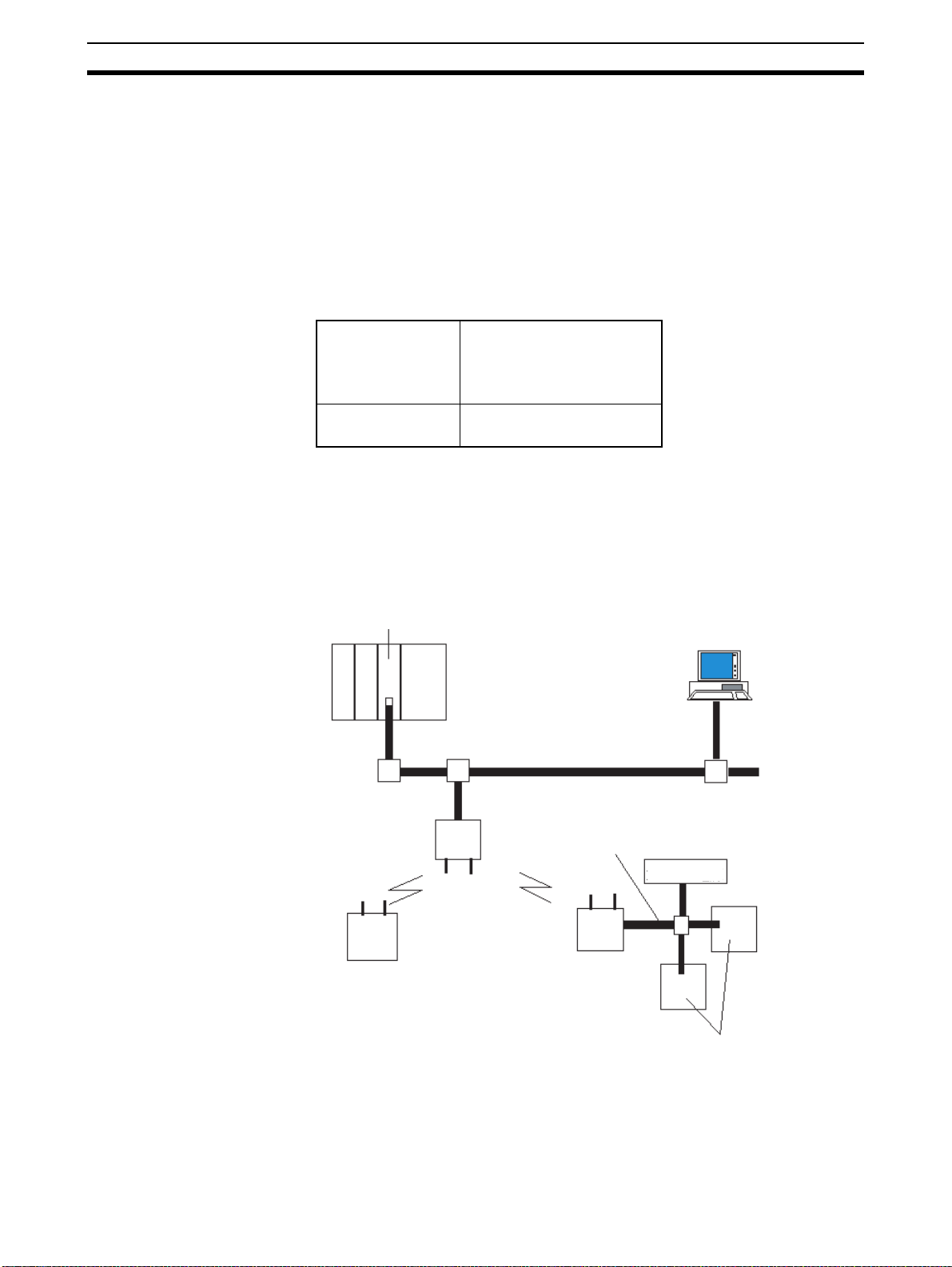
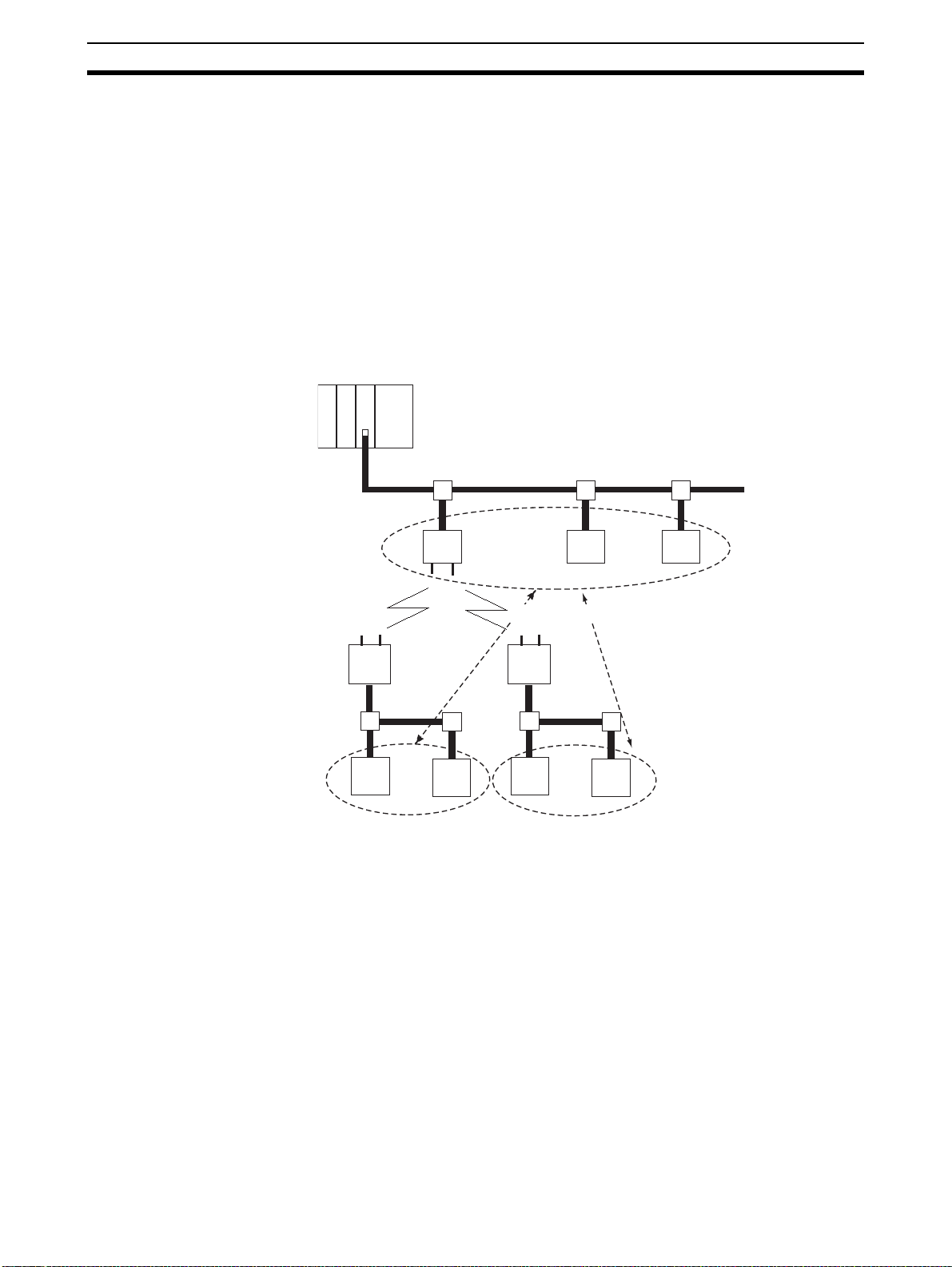
1-1 DeviceNet Wireless Unit
The DeviceNet wireless unit, consisting of a DeviceNet wirel ess master station and a DeviceNet wireless slave station, allows wireless communication
with the DeviceNet slave.
Basically, the wireless master station is connected to th e DeviceNet network
and acts as either a virtual DeviceNet slave or wireless network master station
for the DeviceNet master unit. The wireless slave station acts as either a wireless network s lave station or a virtual DeviceNet mas ter with the DeviceNet
slave unit.
This unit conforms to the following radio wave standards.
WD30-ME/-SE Japan: ARIB STD-T66
USA: FCC part 15.247
Canada: IC RSS 210
Europe: ETS 300 440
WD30-ME01/-SE01 Japan: ARIB STD-T66
USA: FCC part 15.247
Conformance with these standa rds means that the antenna can be instal led
separately. The unit can b e pu rchased as a set with a p enc il an tenn a (WD30ME/-SE) or with a magnet-base antenna (WD30-ME01/-SE01). (The diagrams in this manual are for the WD30-ME/-SE.)
1-1-1 System configuration
DeviceNet master unit
Wireless slave station
Wireless master
station
Wireless network
DeviceNet network
DeviceNet cable
Wireless slave station
Configurator
DC24V power
supply
1-1-2 Features
DeviceNet slaves can be
made wireless
2
DeviceNet slaves
Wireless DeviceNet slaves allows for a variety of field level applications.
Page 15

DeviceNet Wireless Unit Section 1-1
We recommend that this function be used for applications that are not
required to operate in real tim e (such as di splays for indicators and manufacturing instruction data transmissions).
Errors can be monitored DeviceNet sl ave error information (i ncluding e rrors in wir eless slave stations)
can be assigned to two or four status words and monitored from the PLC.
Abundant number of
wireless channels allows
the construction of
multiple systems in the
same area
Relay functions make
possible an extension in
communications
distances
Diversity functions Multi-pass phasing is improved with a diversity system (which requires 2
Maximum number of I/O
per wireless master
station increased
Magnet-base antenna
added to lineup
Since the wireless region is divided into 34 frequencies from 2,400 to
2,483.5MHz, you can sele ct an unused frequency for building multiple systems.
Using a spectral spread me thod (DS: direc t spread) as a mo dulation method
achieves high-quality communications even in areas of excess noise.
Although communications distances vary according to the installation environment, the goal indoors is 60m in line of sight.
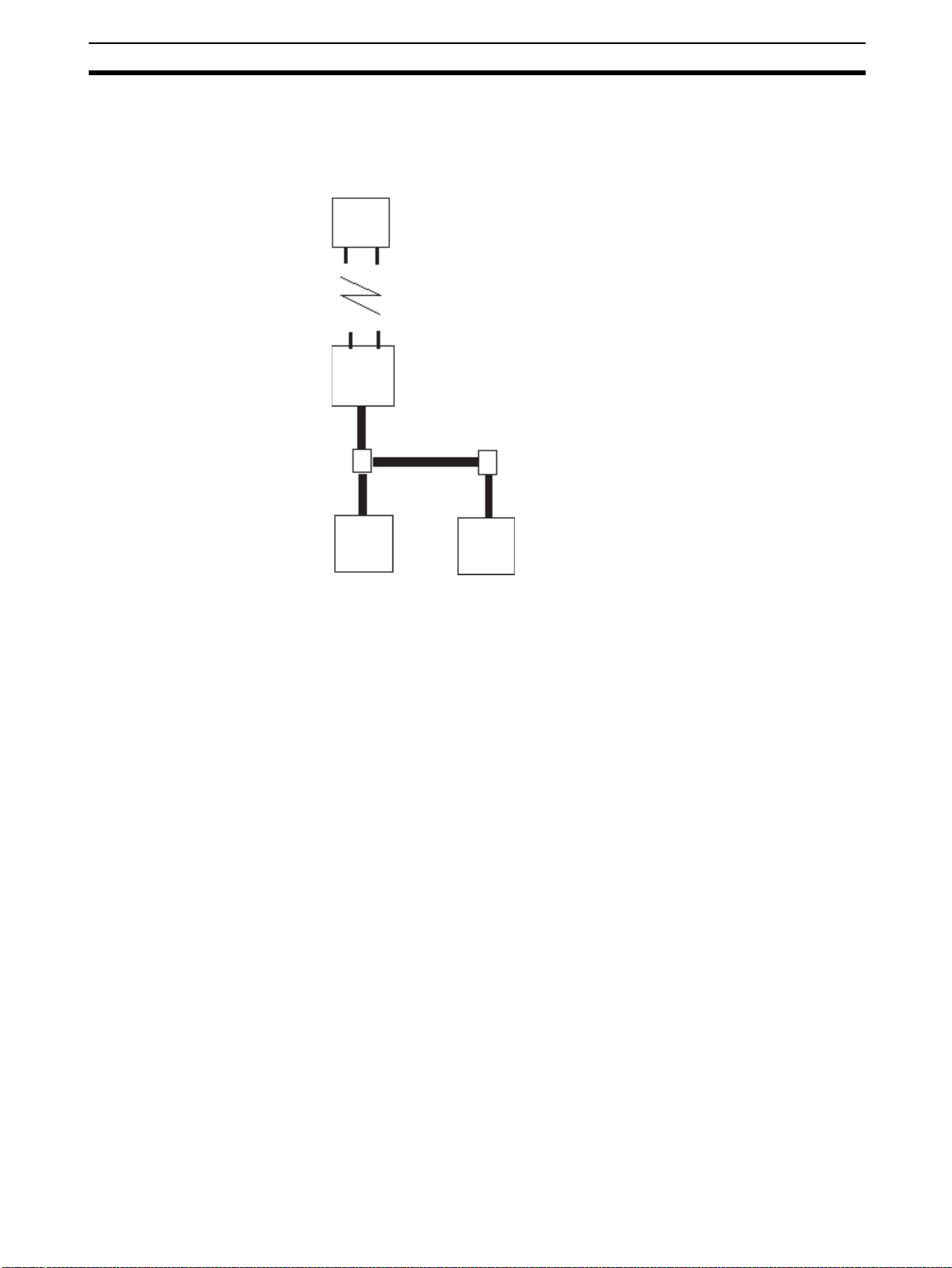
The relay functions allow an increase in the communicati ons area (to a maximum of 3 stages).
DeviceNet slaves may also be connected to the relay station.
However, relay station system settings can only be performed from the config-
urator.
antennas).
The effects of this function are observed when used in areas where variations
in radio waves (such as reflections) occur.
Depending on the switch settings of the wireless master station, the maximum
number of I/O per wireless master station can be increased to 100 words/
100 words (IN/OUT). The maximum number of wireless slave stations that
can be connected has increased to 64.
Using the magnet-base antenna, the station itself can be installed inside a
control panel with the antenna ins talled outside. Al so, because it is mounte d
with a magnet, the p osition of the antenna can be adjusted e asily when, for
example, the control panel is moved. Attenuation in the ante nna cable (2m),
however, limits the maximum communic ations di stanc e to appr oximately 50m
indoors.
1-1-3 Types of units
DeviceNet wireless master
station (Wireless master
station)
Multi-pass
phasing
• Connects to the DeviceNet network and acts as a virtual DeviceNet slave.
• Maximum number of I/O as DeviceNet slave: IN/OUT = 32 words (512
points)/32 words (512 points) or 100 words (1,600 points)/100 words
(1,600 points) dep ending on th e DIP switch setti ng. However, if Status is
selected, IN/OUT = 30 words (480 points)/32 words (512 points) or
96 words (1,53 6 points)/100 words (1 ,600 points) depending on the DIP
switch setting.
• As the wireless networ k ma ste r sta tio n, i t c ontrol s a ma xi mum o f 64 wir eless slave stations and sends remote I/O transmissions.
• The wireless master s tation was tested at the tes t laboratories of a thi rd
part organization authorized by the ODVA. It is authorized as being in
conforming to ODVA conformance software.
Multi-pass phasing is the phenomenon of a radio wave being transmitted form a single point,
passing through multiple propagation paths, and then arriving at a single point.
3
Page 16

Basic Functions of the DeviceNet Wireless Unit Section 1-2
DeviceNet wireless slave
station (Wireless slave
station)
1-1-4 Model list
Type No. of inputs/
DeviceNet
wireless
master station
DeviceNet
wireless slave
station
outputs
None Status: 2 or
None 0 words 0 words None Model
• As an slave station for the wireless network, it exchanges remote I/O communications with the wireless master station via the wireless line.
• Acts as a virtual DeviceNet master with DeviceNet slaves.
• Connects with a maxi mum of 63 DeviceNet slaves and performs a m aximum of 64 words (1,024 points) I/O control. (Even if multiple wireless
slave stations are used, the maximum number of nodes for DeviceNet
slaves is 63.)
No. of words in PLC I/O
memory
IN OUT
0 words None Supplied by
4 words (S ee
note.)
Note When set to “status”
I/O
connection
Unit voltage Installation Model
power for
external
communications
Screws Model
WD30-ME
Model
WD30ME01
WD30-SE
Model
WD30SE01
Accessories The following accessories are in cluded with purchase of both wireles s mas ter
station and slave station:
• 2 antennas (ME/-SE: pencil antenna; ME01/-SE01: magnet-base
antenna)
• User’s manual
• Sticker (Attach in a visible location.)
• 2 installation screws (with nuts)
• Declaration of Conformity (CE) (Provided with ME/-SE models only.)
Applicable connectors Use DeviceNet micro-connectors for communications connectors. A list of
recommended connectors in the appendix.
1-2 Basic Functions of the DeviceNet Wireless Unit
1-2-1 Replacing data
Initializing the wireless
master station
When the power supply is tur ned on, the wirele ss master station add s each
registered wireless slave station. When wireless communicati on begins with
an slave station, if the number of I/O points on the DeviceNet slave connected
to the slave station and the I/O points registered for the wireless m aster station are identical, it is added. If they are not identical, an I/O configuration
error will occur.
4
Page 17
Basic Functions of the DeviceNet Wireless Unit Section 1-2
Processing when an error
occurs
DeviceNet master unit
I/O configuration check
Addition process
DeviceNet network
Wireless master station
I/O points
WNODE IN points
1 word (16 points) 1 word (16 points)
01
---
Wireless network
Wireless slave station
WNODE=01
I/O points
IN: 1 word (16 points), OUT: 1 word (16 points)
--- ---
OUT points
Configurator
If the number of I/O points on
the wireless master station
and the wireless slave station
is different, an I/O
configuration error will occur.
Even if an error occ urs in the DeviceNet network b elow a wirele ss slave station after initialization is complete, the wireless network polling communication
will continue as normal. The user should monitor the status at his device
(PLC, computer) when an error occur s, and apply the appropria te error processing program for the type of error and the area in which it occurred.
5
Page 18
Basic Functions of the DeviceNet Wireless Unit Section 1-2
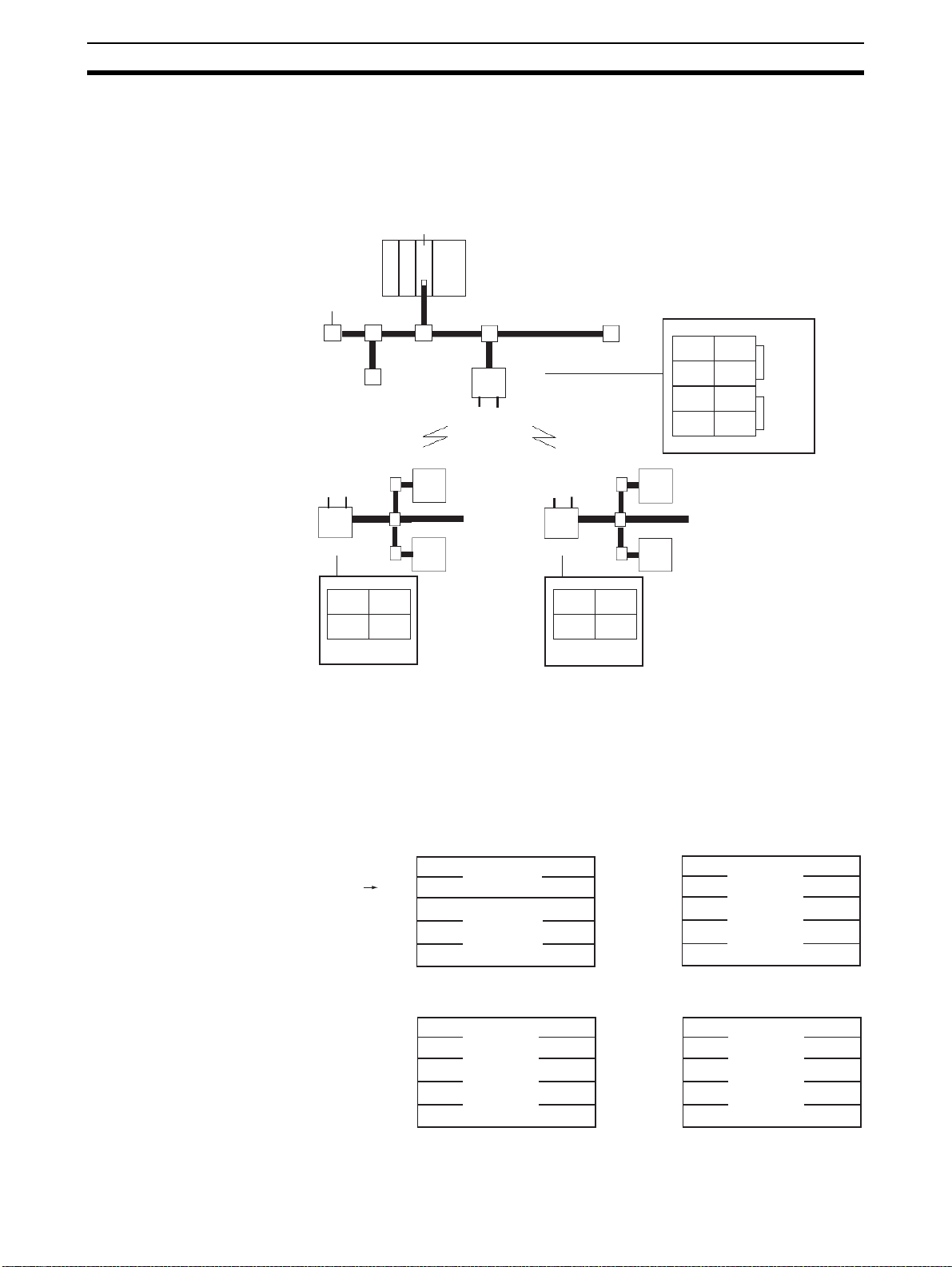
1-2-2 I/O allocation
I/O for DeviceNet slaves is allocated in the wireless slave stations by ascending order of DeviceNet nod e address wit hout leaving any unused ar eas, and
then in the wireless m aster station by ascending orde r of slave station wireless node address (WNODE) without leaving any unused areas.
DeviceNet master unit
Network power supply
DeviceNet slaves
#2
Wireless network
DeviceNet network
Wireless
master
station
Terminal resistor
DeviceNet slaves
IN
#3 IN #3 OUT
#4 IN
# 1 IN #1 OUT
#2 IN
Allocated in ascending order of WNODE
OUT
#4 OUT
#2 OUT
#4
WNODE=01
WNODE=02
Wireless slave
station
WNODE=02
IN
OUT
#1 IN #1 OUT
#2 OUT
#2 IN
Allocated in ascending
order of DeviceNet node
address
DeviceNet slaves
#1
Wireless slave
station
WNODE=01
IN
#3 IN #3 OUT
#4 IN
Allocated in ascending
order of DeviceNet node
address
DeviceNet slaves
#3
OUT
#4 OUT
• The IN and OUT areas are alloc ated in uni ts of 16 points (1 word). In the
case of 8-point units, the lower byte (bits 0 to 7) is allocated and the upper
byte (bits 8 to 15) is set to 00 Hex.
• The following four types of I/O allocations can be set using the DIP switch.
1,2,3... 1. Status 2 words (32 points), I/O IN/OUT = 30 words ( 480 poi nts)/32 words
(512 points)
015
For wireless master
station NNODE
IN area
Wd+0
+1
+31
Status
(2 words, fixed)
IN
(Max. 30 words)
015
OUT area
Wd+0
+1
+31
OUT
(Max. 32 words)
2. I/O IN/OUT = 32 words (512 points)/32 words (512 points)
IN area OUT area
Wd+0
+1
IN
015
Wd+0
(Max. 32 words)
+31
+1
+31
15
(Max. 32 words)
0
OUT
6
Page 19

Basic Functions of the DeviceNet Wireless Unit Section 1-2
3. Status 4 words (64 points), I/O IN/OUT = 96 words (1,536 points)/
100 words (1,600 points)
INarea
Wd+0
+99
+1
Status
(4words,fixed)
IN
(Max.96words)
015
OUTarea
Wd+0
+1
OUT
(Max.100words)
+99
015
4. I/O IN/OUT = 100 words (1,600 points)/100 words (1,600 points)
INarea OUTarea
Wd+0
+1
IN
(Max.100words)
+99
015
Wd+0
+1
+99
OUT
(Max.100words)
015
The default settings are "(2) I/O IN/OUT = 32 words (512 points)/32 words
(512 points)".
7
Page 20
Basic Functions of the DeviceNet Wireless Unit Section 1-2
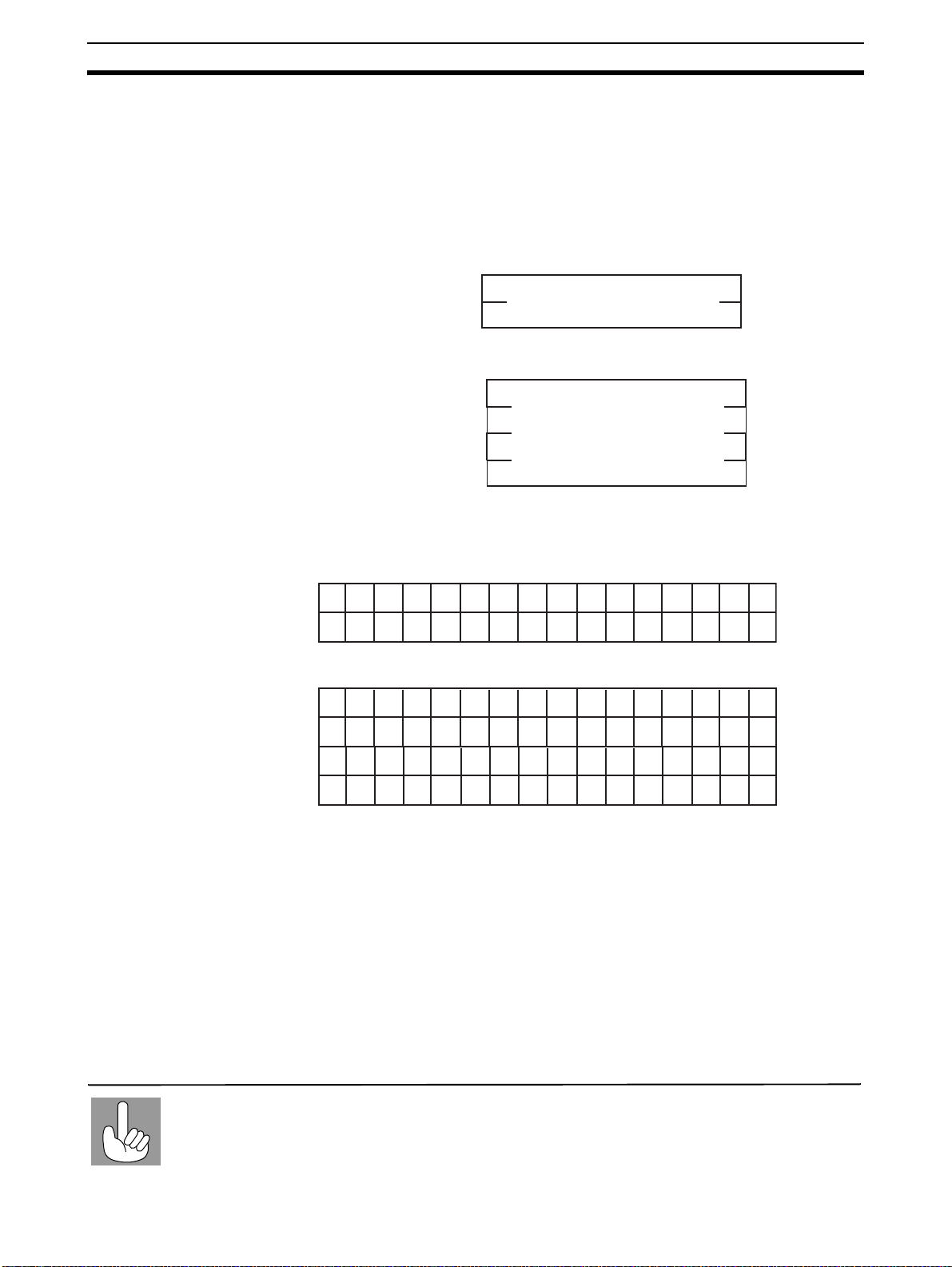
1-2-3 De viceNet wireless unit status
The format for the IN area status area is shown below.
Confirm this status at the CPU unit, and prepare an error processing program
for sending commands to (Expl icit messages) and obtaining de tailed status
reports (wireless network status, DeviceNet master status) from wireless
master stations showing error flags. (Refer to SECTION 3 Sample Program.)
1. When maximum number of I/O = 32 words/32 words:
0
187
Status begins Wd+0
Wd+1
15
Slave error flag
2. When maximum number of I/O = 100 words/100 words:
0
187
Status begins Wd+0
Wd+1
Wd+2
Wd+3
15
Slave error flag
1-2-4 Slave error flag
Master unit
I/O point
limitations
1. When maximum number of I/O = 32 words/32 words:
15 14 13 12 11 10 9 8 7 6 5 4 3 2 1 0
16 15 14 13 12 11 10 9 8 7 6 5 4 3 2 1
32 31 30 29 28 27 26 25 24 23 22 21 20 19 18 17
2. When maximum number of I/O = 100 words/100 words:
15 14 13 12 11 10 9 8 7 6 5 4 3 2 1 0
16 15 14 13 12 11 10 9 8 7 6 5 4 3 2 1
32 31 30 29 28 27 26 25 24 23 22 21 20 19 18 17
48 47 46 45 44 43 42 41 40 39 38 37 36 35 34 33
64 63 62 61 60 59 58 57 56 55 54 53 52 51 50 49
Each of the following for the DeviceNet mas ter st a tus of added wireless s lave
stations is set to an OR value.
Incorrect switch setting/EEPROM error (bit address 00)
Repetitive node address/Busoff detection (bit address 01)
Configuration error (bit address 03)
Structural error (bit address 04)
Send error (bit address 05)
Communication error (bit address 06)
Verify error (bit address 07)
Also, if a wireless slave station has been registe red but not added, the bit wi ll
be 1. For example, if a wireless slave station error oc curs for WNODE = 16,
the uppermost bit for "status begin word +0" (16) becomes 1.
Each wireless master station can control a maximum of 512 (or 1,600) I/O points. However, there
are limits to the number of I/O points per node for each master unit. Therefore, systems should
be designed without exceeding the limitations for the number of I/O points per node for each
master unit.
8
Page 21

Basic Functions of the DeviceNet Wireless Unit Section 1-2
Refer to the "DeviceNet User’s Manual" for details concerning DeviceNet
master status errors.
1-2-5 Disconnect/Connect Switch
The Disconnect/Connect Switch function that was introduced with CS/CJseries DeviceNet master uni ts c an b e us ed for wireless sl ave stations. A bit is
allocated to each wirel es s sl ave station’s WNODE, and if this bit is turned ON
(1), wireless I/O com municat ions and mess age communi cati ons with t he cor responding wirele ss slave station will stop (i.e., the wireless slave station is
disconnected from the network). This function is mainly used to reserve space
for wireless slave stations to be added in the future (i.e., I/O point s have been
registered in the wireless master station but no wireless slave station has
been connected yet).
Wireless slave stations tha t have been disc onnected from the net work do no t
need to be considere d when calculating the wireless communic ations cycle
time.
In the DeviceNet master unit’s I/O area, 0 is set in the IN area allocated to
wireless slave stations that have been set to leave the network.
9
Page 22
Basic Functions of the DeviceNet Wireless Unit Section 1-2
1-2-6 DeviceNet node addresses
DeviceNet node addresses (NNODEs) are included in wireless master stations. The master unit controls the assignment of DeviceNet slave I/O data
registered with wirele ss slave stations to areas corresp onding to these node
addresses.
Wireless node add resses (WNODEs) are included in wir eless slave stations.
These node addresses are used for control by wireless master stations.
Therefore, there is no purpose in assigning the wireless slave station
DeviceNet node addresses (NNODEs) to I/O. Normally, a 7 segment LED is
used to display the DeviceNet node address on wireless slave stations.
Since DeviceNet node addresses are controlled by wireless slave stations, be
sure to set the DeviceNet slaves so that there is no redundancy.
DeviceNet master unit
DeviceNet network
There should be no
redundancy within this area.
Wireless master
station
DeviceNet slaves
Wireless network
Wireless slave
station
DeviceNet slaves DeviceNet slaves
There should be no redundancy within this area.
Redundancy is acceptable in this area.
Wireless
slave
station
10
Page 23
Basic Functions of the DeviceNet Wireless Unit Section 1-2
1-2-7 DeviceNet wireless unit default setting values
Wireless unit network default settings are on a 1:1:2 structure of wireless
master station: wireless slave station: DeviceNet slave with IN/OUT = 16
points/16 points, as shown in the figure below.
Wireless master station
I/O points: IN 1 word (16 points)
OUT 1 word (16 points)
Registered wireless slave station: 1 node
Wireless slave station
WNODE=01
IN/OUT=1 word (16 points) 1 word (16 points)
DeviceNet slave
NNODE=01
IN/OUT=
(16 points/0 point)
The default settings ca n be retur ned to on b oth wireles s master sta tions and
slave stations using the DIP switches in SET mode. Refer to 2-4 System Initial
Setting and Starting Communications for detailed setting information.
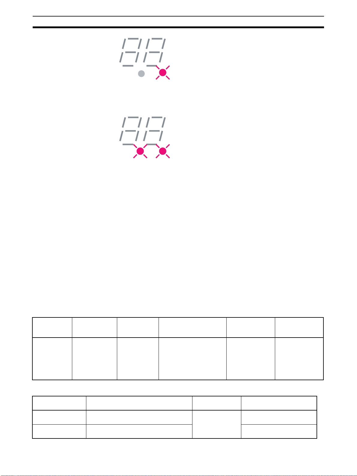
1-2-8 Serial Number Check
With the release of the WD30-ME wi th Identity Ob ject Revision value 3.02, it
has become possible to register the serial number (the wireless slave station’s
own unique ID) of wireless slave stations to non-volatil e memory in th e wireless master station.
If a wireless slave station is registered to a wireless master station using
switch operations at the wire less master sta tion, or if seri al number check is
enabled for the wireless slave station by editing the device parameters using
the configurator, and the seria l number is wr itten, the wi reless sl ave station’s
serial number is re gistered to the wireles s master s tation’s non-volatile memory.
This function is for preventing incorrect WNODE settings for wireless slave
stations, and communications errors resulting from the effects of intermodulation.
If serial number check is enabled for all the wireless sl ave stations registered
to a wireless master station, the dot on the right-hand side of the wireless
master station’s 7-segment LED lights.
DeviceNet slave
NNODE=02
IN/OUT=
(0 point/16 points)
11
Page 24
Configurator Outline Section 1-3
Also, if serial number check is enabled for all the wireless slave stations registered to a wireless master station, an d a ll of the wir e les s slave stations’ se rial
numbers are registered to the wireless master station, the dot on the left-hand
side of the wireless master station’s 7-segment LED lights.
1-3 Configurator Outline
This is the Windows application that runs the DeviceNet computer master station.
Master and slave unit settings can b e referenced (s lave entry, I/O allocations,
wireless network p rotocol parameters, commands issued), conditi ons monitored, used frequency bands (channels) monitored, and running tests performed from the DeviceNet configurator (V er. 2.0 or later).
1-3-1 Configuration
The computer running the Configurator is connected to the DeviceNet network by installing a n OMRON DeviceNet Board in the computer or by connecting the computer to a s erial commun ications por t (per ipheral por t) of th e
CS1W-DRM21 DeviceNet Unit on a CS1-series PLC.
Note In both cases, the same online functions are supported.
1-3-2 Operating environment
This is the operating environment for the DeviceNet configurator.
Product Model Contents Method of connecting
Configurator
(Ver. 2.@)
WS02-CFDC1-E Installation disk
(CD-ROM)
Note Use the following dedicated Boards and Card
Model Contents Personal
3G8F5-DRM21 Dedicated ISA Board and Configurator
3G8E2-DRM21 Dedic ated PCMC IA Card and Conf igu rator
(Ver. 2.@) installation disk
(Ver. 2.@) installation disk
personal computer to
network
Either one of the following
methods
• Serial connection
• Dedicated PCMCIA Card
• Dedicated ISA Board
(see table below)
IBM PC/AT or
compatible
computer
Personal
computer
IBM PC/AT or
compatible
Windows 95, 98 or NT4.0
Windows 95 or 98
OS
Windows 95, 98,
2000 or NT4.0
OS
12
Page 25

Configurator Outline Section 1-3
1-3-3 Outline of functions
• Monitor the network condition of the wireless unit
• Set and reference parameters of the wireless unit (setting/referencing
wireless slave entry, number of I/O points, and wireless slave station routing information)
• Monitor channels (monitor the transmission levels of used frequency
bands, and keep logs)
• Running test (perform running tests according to user configurations without grouping PC and PLC applications, and leave a test log with time
information)
• Wireless communication cycle time calculation
Refer to SECTION 8 Using the Configurator for a detailed explanation of
these functions.
13
Page 26

Application Limitations Section 1-4
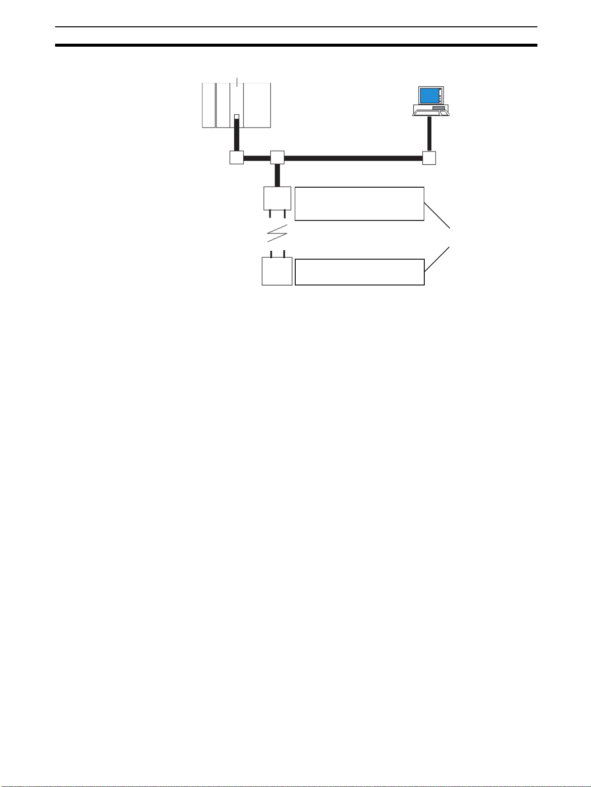
1-4 Application Limitations
The wireless unit is not des igned to b e com patible with every type of appl ication that uses DeviceNet. Do not use the unit with the following applications.
1,2,3... 1. Applications that require real-time control
Do not use the unit with applications th at r e qui re r eal -tim e c on tr ol. In par ticular, it cannot be used under conditions that require responsiveness
greater than that outlined in "Section 9 Communications Timing".
Applications that do not require real-time control, such as indicators, equipment error monitors, and parts picking operation, are recommended.
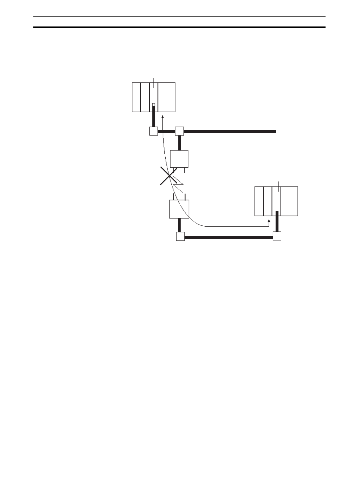
2. Applications that use FINS message communications
Wireless units do not support FINS message com munic ati on s. For exam-
ple, although CX-Programmer Ver. 2.1 and later versions suppor t online
connection (i.e., remote programming and monitoring) to PLCs on DeviceNet networks (e.g., PLCs with CS/CJ-series DeviceNet Units or programmable slaves), this functionality is not available via wireless units.
CX-Programmer
installed on a
computer
CS1
Wireless master
station
Wireless slave
station
Upper DeviceNet network
Programmable slave
Lower DeviceNet network
14
Page 27
Application Limitations Section 1-4
3. Applications that use Peer to Peer communications between the upper DeviceNet network DeviceNet master and the lower DeviceNet net-work DeviceNet master.
DeviceNet master unit
Upper DeviceNet network
Wireless master
station
DeviceNet master unit
Wireless network
Wireless slave
station
Lower DeviceNet network
15
Page 28
Points for Consideration with Wireless Systems Section 1-5
4. Applications that require setting the DeviceNet slave "Communication
Error Output" to "Standby"
When a wireless slave station is reset from som e error, it is possible that
the DeviceNet slave output will be moment arily cleared. T herefore, applications that set the output t o "Standby" dur ing co mmunicat ion error s can
not be used.
DeviceNet master unit
Upper DeviceNet network
Wireless master
station
Wireless network
Wireless slave
station
Lower DeviceNet network
Output set to
"Standby" during
DeviceNet slaves
transmission errors
OUT
Cleared momentarily
5. Applications where software reset (Explicit messages) must be performed
for the slave station from the upper DeviceNet network
1-5 Points for Consideration with Wireless Systems
1-5-1 Construction of mul t iple wireless systems
When construc ting a system for using multiple wi reless master stations, th e
following points must be considered. Consult your OMRON representative.
16
Page 29
Points for Consideration with Wireless Systems Section 1-5
Setting wireless channels It is necessar y to select frequencies for the wireless channels that are not
interfered with by radio waves. (Radio inter ference can be handled by retr y
processes between the wireless networks, but will lengthen the system
response time.)
With this unit, 34 wireless channels can be selected from. Taking the following
points into consideration, however, the maximum number of wireless systems
usable in a single area without radio interference is, as a rough guide, 10.
1. It is possible that, for example, there is a wireless LAN on site that uses the
same frequency as this unit. Select an unused wireless channel using the
Configurator’s wireless channel monitor function.
2. Do not select neighboring wireless channels as they have a large amount
of interference.
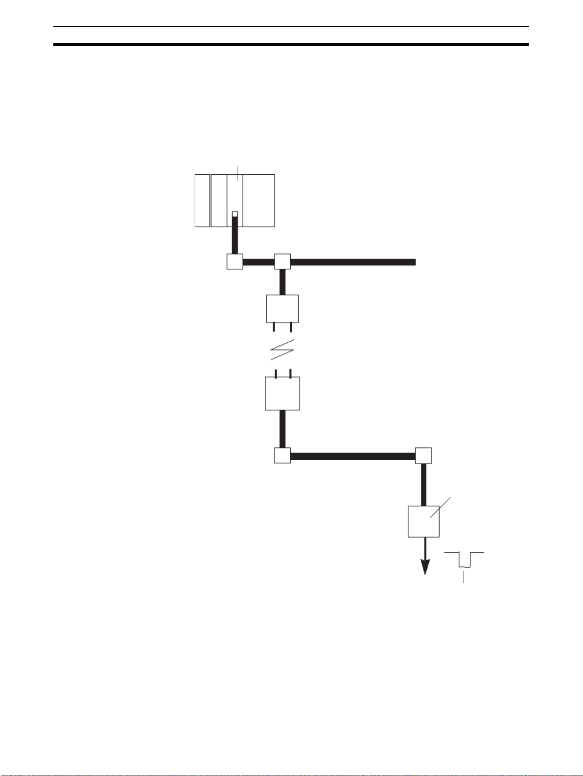
3. Due to the fundamental nature of radio waves, if 2 or more waves with different frequencies are output at exactly the same time, mutual interference
will occur between the different frequencies, and new waves will be generated with frequencies at intervals equal to the intervals between the output
frequencies. (This phenomenon is called “intermodulation.”)
1
-(f2 - f1)=1ch
f
Radio wave created
by intermodulation
Wireless master
station
Wireless slave
station
f1=5ch f2=9ch
Wireless master
station
Wireless slave
station
f2+(f2 - f1)=13ch
Radio wave created
by intermodulation
Do not select the frequencies of waves created by intermodulation.
Antenna separation
distance
The distance be tween wireless unit s has a large influ ence on the amou nt of
interference received. In par ticular, there may often be cases where wireless
master stations are installed relatively closely to each other. Separate the
antennas for different wireless master st ations by at least 1 m (at least 2 m, if
possible).
Test c onfirmation Perform a test to see whether or not the wireless units are rece iving interfer-
ence. Using the Configurator’s running test function, obtain the packet error
rate, and, based on this, determine whether or not the communications quality
is sufficient for the appl ication. (As a r ough guide, the packet rate should b e
less than 0.01.)
Intermodulation
Due to the fundamental nature of radio waves, if 2 or more waves with different frequencies are
output at exactly the same time, mutual interference will occur between the diff erent frequencies,
and new waves will be generated with f requencies at intervals equal to t he intervals betw een the
output frequencies.
17
Page 30

Points for Consideration with Wireless Systems Section 1-5
!Caution Communications errors caused by intermodulation
Communications errors and retry proces sing may occur due to inter modulation and consequently cause transmission delays. In order to eliminate the
influence of intermodulation, do not set the wireless channels for wireless
units in every system to frequencies at regular intervals.
Before starting ope ration o f th e wi r ele ss sy ste m u sing a W D30-ME with Identity Object Revision value 3.02, eithe r register wireless slave stations to the
wireless master station using switch operations at the wireless master station,
or enable serial number check for the wireless slave stations using the configurator, and then register the seri al numbers of the wireless slave stations to
the wireless master station by writing the serial numbers.
18
Page 31

SECTION 2
Hardware Settings and Checking of Operations
This section gives specific explanations of t he op erati ons an d p roce dures n eces sary for you to u se the DeviceNet wire less u nit. Follow
the explanations in this section t o perform operation check procedure s.
2-1 Basic Operation Procedure . . . . . . . . . . . . . . . . . . . . . . . . . . . . . . . . . . . . . . . 20
2-1-1 Basic operation procedures flowchart. . . . . . . . . . . . . . . . . . . . . . . . 20
2-2 Pre-work Preparations. . . . . . . . . . . . . . . . . . . . . . . . . . . . . . . . . . . . . . . . . . . 22
2-2-1 Determination of system configuration . . . . . . . . . . . . . . . . . . . . . . 22
2-2-2 Confirmation of specifications . . . . . . . . . . . . . . . . . . . . . . . . . . . . . 22
2-2-3 Temporary installation and installation test . . . . . . . . . . . . . . . . . . . 23
2-3 Hardware Settings and Wiring . . . . . . . . . . . . . . . . . . . . . . . . . . . . . . . . . . . . 24
2-3-1 DeviceNet wireless master station settings and installation. . . . . . . 24
2-3-2 DeviceNet wireless slave station settings and installation . . . . . . . . 24
2-3-3 Installation of connection equipment . . . . . . . . . . . . . . . . . . . . . . . . 25
2-3-4 Cable connections . . . . . . . . . . . . . . . . . . . . . . . . . . . . . . . . . . . . . . . 25
2-4 System Initial Setting and Starting Communications . . . . . . . . . . . . . . . . . . . 26
2-4-1 System start. . . . . . . . . . . . . . . . . . . . . . . . . . . . . . . . . . . . . . . . . . . . 26
2-4-2 DeviceNet slave entry. . . . . . . . . . . . . . . . . . . . . . . . . . . . . . . . . . . . 27
2-4-3 DeviceNet wireless slave station entry . . . . . . . . . . . . . . . . . . . . . . . 29
2-4-4 Scan list valid settings. . . . . . . . . . . . . . . . . . . . . . . . . . . . . . . . . . . . 31
2-5 Operation Confirmation . . . . . . . . . . . . . . . . . . . . . . . . . . . . . . . . . . . . . . . . . 31
2-5-1 Unit LED confirmation. . . . . . . . . . . . . . . . . . . . . . . . . . . . . . . . . . . 31
2-5-2 Status confirmation. . . . . . . . . . . . . . . . . . . . . . . . . . . . . . . . . . . . . . 31
2-5-3 Confirmation by reading/writing data . . . . . . . . . . . . . . . . . . . . . . . 32
2-6 Other Operations. . . . . . . . . . . . . . . . . . . . . . . . . . . . . . . . . . . . . . . . . . . . . . . 32
2-6-1 DeviceNet wireless slave station deletion. . . . . . . . . . . . . . . . . . . . . 32
2-6-2 DeviceNet wireless master station initialization. . . . . . . . . . . . . . . . 35
2-6-3 DeviceNet wireless slave stations initialization . . . . . . . . . . . . . . . . 36
2-7 Deciding the Antenna Installation Position . . . . . . . . . . . . . . . . . . . . . . . . . . 38
2-7-1 Example of installation inside a control panel . . . . . . . . . . . . . . . . . 41
19
Page 32

Basic Operation Procedure Section 2-1
2-1 Basic Operation Procedure
Specific examples illustratin g the basic opera tion procedu re of the DeviceNet
wireless unit are given in this section.
2-1-1 Basic operation procedures flowchart
The basic operation procedure is shown below. Refer to the "DeviceNet
User’s Manual" and the "DeviceNet Slave Manual" for details concerning s ettings and connections.
Pre-work confirmation
Determination of system configuration
(See page 22).
Hardware settings and
wiring
Confirmation of specifications
Temporary installation and installation test
DeviceNet Wireless master station settings and installation
DeviceNet
Installation of connection equipment
Cable connections
Wireless slave station settings and installation
(See page 22).
(See page 23).
(See page 24).
(See page 24).
(See page 25) .
(See page 25).
System initialization and
starting communication
20
System start
DeviceNet slave entry
DeviceNet wireless slave station entry
Scan list valid settings
(See page 26).
(See page 27).
(See page 29) .
(See page 31).
Page 33

Basic Operation Procedure Section 2-1
Operation confirmation
Unit LED confirmation
Confirmation by reading/writing data
(See page 31).
(See page 32) .
21
Page 34

Pre-work Preparations Section 2-2
2-2 Pre-work Preparations
Items to be checked before performing installation work are explained
here.
2-2-1 Determination of system configuration
A single wireless ma ster station is limited to a maximum of 1,02 4 or 3,200
points, 512 (32 words) or 1,600 (100 words) points each for both IN and OUT.
In addition, the maximum configu ration in a wireless network of master stations to slave stations is 1 to 32 or 1 to 6 4, and the maximum numbe r of IN/
OUT points for the entire s ystem is limited by the DeviceNet mast er un it. Th is
should be considered carefully when determining system configuration.
System configuration
example
DeviceNet master unit
Model CS1W-DRM21
(NNODE=10)
Wireless network
Wireless slave
station
(WNODE=01)
(NNODE=00)
DeviceNet slaves
Model DRT1-ID08C
(NNODE=01)
DeviceNet slaves
Model DRT1-MD16C
(NNODE=03)
In this section, the operation procedu re is explained using the following system configuration as an example.
A communications power supply (Model S82K) has been purposely left out
DeviceNet network
Wireless mater station
(NNODE=00)
Wireless slave
station
(WNODE=02)
(NNODE=00)
DeviceNet slaves
DRT1-ID08C
Model
NNODE=2
(NNODE=02)
DeviceNet slaves
Model DRT1(NNODE=04)
DRT1-ID08C
MD16C
NNODE: DeviceNet node address
WNODE: Wireless node address
ModelDRT-ID08C: 8 environment-resistant
terminal inputs
ModelDRT1-MD16C: 16 environment-resistant
terminal inputs/outputs
of the diagram above. It should be connected and supply power to the
DeviceNet network (both upper and lower) and s hould be con nected wit h terminating resistor. In addition, an external power supply shou ld be conne cted
to the environment-resistant terminal of the DeviceNet slave.
2-2-2 Confirmation of specifications
Confirmation of number of
IN/OUT points
Master unit
I/O
limitations
22
Confirm that th e number of IN/O UT points for each wirel ess master station is
no more than 512 or 1,600 (32 or 100 words).
In the example, the number of IN points is 8
points is 8
A single wireless master station can control up to 512 points (or 1,600 points) for both input and
output, but the number of I/O points per node is limited by the master unit. Be careful not to
exceed the limit for I/O points per master unit node when constructing your system.
× 2 = 16.
× 4 = 32, and the number of OUT
Page 35

Pre-work Preparations Section 2-2
W NODE
0
1
2
3
4
5
W NODE
0
1
2
3
4
5
Confirmation of wiring A special communications cable is required to connect to the DeviceNet
micro-connector on the wireless unit.
In addition, if multiple DeviceNet slaves are connected, branch taps should be
used as necessar y. Terminators for the wireless slave station DeviceNet network should also be prepared. Refer to the "DeviceNet User’s Manual" for
details.
Confirmation of
communications power
supply
Since power is supplied to the wireles s unit from an extern al communic ations
power supply, a communications power connection must be made.
Taking the maximum current at startup into consideration, use a power supply
of at least 350mA. If using an OMRON S82K or S82 J switching power supply,
use a model with a capacity of at least 30W (S82K) or 25W (S82J).
2-2-3 Temporary installation and installation test
Temporary installation of
wireless master station
Set the switches as shown below, and temporarily fix the master station in the
determined location.
Master station
• SW3=bit4 ON (positioning test)
0
1
9
9
RUN
TEST
SET
SW2
X10
X10
8
7
6
W CH
0
9
8
7
6
ON
1
2
2
3
4
5
1
2
3
4
5
SW3
3
4
8
7
6
0
1
9
2
8
3
7
4
6
5
X1
5
7
8
6
• Mode select switch = TEST
• WNODE = test subject’s wireless
• WCH = 01
Connect a DeviceNet cable prepared for a micro-connector, and connect th e
DC24V communications power supply.
slave station WNODE
(This example starts at WNODE
= 01.)
Temporary installation of
wireless slave station
Performing the installation
test
Set the switches as shown below, and temporarily fix the master station in the
determined location.
Slave station
• SW3=bit4 ON (installation test)
0
RUN
TEST
SET
SW2
X10
X10
9
8
7
6
W CH
0
9
8
7
6
ON
1
2
1
2
3
4
5
1
2
3
4
5
SW3
3
4
9
8
7
6
0
1
9
2
8
3
7
4
6
5
X1
5
7
8
6
• Mode select switch = TEST
• WNODE = WNODE for each
wireless slave station (WNODE
= 01 to 02 for this example.)
Connect a DeviceNet cable prepared for a micro-connector, and connect th e
DC24V communications power supply.
Perform the positioning test. (Refer to 5-2 Installation Test for details concern-
ing the procedure.) Onc e you have confirmed that wireless c ommunications
are stable, ensure that they remain stable by securing the wireless unit in
position. (Refer to 2-7 Deciding the Anten na Installation Position for details.)
In this example, an installation test is perfor med between the wire less mas ter
23
Page 36

Hardware Settings and Wiring Section 2-3
station and slave station 1, and the wir eless mast er station and slave station
2.
2-3 Hardware Settings and Wiring
Settings and wiring to be performed before turning on the power supply to the
system are explained in this section.
2-3-1 DeviceNet wireless master station settings and installation
Settings An example setting for a wireless master stati on is shown bel ow. Refer to 4-1
DeviceNet Wireless Master Stat ion Specifications for details conc erning setting procedures. In th is example, Status is selected and IN/OUT = 512/512
points (32 words/32 words).
DeviceNet master unit
Model CS1W-DRM21
(NNODE=00)
DeviceNet Network
Wireless master
station
Model WD30-M
SW3=bit6 ON
SW1=bit3 ON
WNODE=01
NNODE=10
Mode select switch = SET
Installation Use screws to firmly fix the wireless master station that has already been tem-
porarily in stalled. Refer to 4- 1 DeviceNet Wireless Master Station Speci fica-
tions for details.
2-3-2 De viceNet wireless slave station settings and installation
Settings Settings example for each wireless slave station ar e shown below. Refer to 4-
2 DeviceNet Wireless Slave Station Specificatio ns for details concerning the
setting procedure.
In this example, the default settings should be used for all DeviceNet setti ngs
apart from the node address. Refer to the "DeviceNet Slave Manual" for
details concerning the settings for each DeviceNet slave.
24
Terminating
resistor
installation
Terminating resistors are required not only for the wireless master station, but also on both ends
of the wireless slave stations’ DeviceNet network.
Page 37

Hardware Settings and Wiring Section 2-3
Wireless master station
SW3=bit6 ON
SW1=all OFF
WNODE=01
NNODE=00
Mode select switch=SET
Wireless network
Wireless
slave
station
DeviceNet slaves
Model DRT1-ID08C
(NNODE=01)
DeviceNet slaves
Model DRT1-MD16C
(NNODE=03)
Wireless
slave
station
SW3=bit6 ON
SW1=all OFF
WNODE=02
NNODE=00
Mode select switch=SET
DeviceNet slaves
Model DRT1-ID08C
(NNODE=02)
DeviceNet slaves
Model DRT1-MD16C
(NNODE=04)
Installation Use screws to firmly fix the wireless slave stations that have already been
temporarily installed. Refer to 4-2 DeviceNet Wireless Slave Station Specifica-
tions for details.
2-3-3 Installation of connection equipment
Connection equipment that requires installation is listed below.
• Shielded T-type branch connector
• Shielded terminating resistor
• Communications power supply (DC24V)
2-3-4 Cable connections
Connect a DeviceNet cable prepared for micro-connectors to the wireless
master and slave stations.
Connect the cables to the DeviceNet master (C2 00HW-DRM21-V1) and the
DeviceNet slave (environment-resistant terminal) to create the complete physical system network.
Example 1:
Connecting the cable on the side and installing a terminating resistor
Plug
Socket
Model DRS2-1
Shielded terminating resistor
Plug
Socket
Model
DCN2-1
Plug
Socket
Dedicated cable
25
Page 38

System Initial Setting and Starting Communications Section 2-4
r
Example 2:
Connecting the cable to the top, and installing a terminating resistor
Special cable
Plug
Socket
Model DRS2-2
Socket
Plug
Socket
Model
DCN2-1
Plug
Example 3:
Connecting the cable to the bottom, and installing a terminating resistor
Model DRS2-1
Shielded terminating resisto
Plug
Socket
Model DCN2-1
Plug
Socket
Plug
Socket
Dedicated cable
2-4 System Initial Setting and Starting Communications
The required entr ies, and deletion and initia lizatio n proce dures following sy stem start are explained in this section.
2-4-1 System sta rt
Turn on the communications power source and the node power supply in the
following order.
1,2,3... 1. DeviceNet slave (environment-resistant ter mi nal ) external power suppl y
2. DeviceNet master (C200HW-DRM21-V1) power supply
It is also OK to turn all power supplies on simultaneously.
26
Page 39

System Initial Setting and Starting Communications Section 2-4
S
S
S
n
W NO
0
1
2
3
4
5
W NO
0
1
2
3
4
5
2-4-2 De viceNet slave entry
Register the number of DeviceNet slave I/O points in the wi reless slave station.
If the same system configurati on as for the network default settings (Refer to
1-2 Basic Functions of the DeviceNet Wireless Unit.) is used, there is no need
to do this registration.
The specifics of this example are explained below.
First, begin with the WNODE = 1 wireless slave station.
Slave station
MS NS W
N NODE
0
1
9
2
8
3
7
4
6
5
X10
SW1
ON
1
2
lave statio
MS NS W
N NODE
0
1
9
2
8
3
7
4
6
5
X10
SW1
ON
1
2
Slave station
RUN
TEST
SET
1. Confirm that the slave station node
address (NNODE) is not doubled
with the DeviceNet slave. In this example, NNODE-00 is OK.
0
1
9
2
8
RUN
3
7
4
6
5
TEST
X1
SET
3
4
SW2
2. Check if the communications rate for
the slave station and the DeviceNet
slave is the same. In this example,
0
1
9
2
8
RUN
3
7
4
6
5
TEST
X1
SET
3
4
SW2
since default settings (125kb ps) are
used, all of the bi ts for SW1 should
be OFF.
3. Since the DeviceNet slave is regis-
SW2
X10
X10
9
8
7
9
8
7
6
ON
1
0
1
4
6
5
W CH
0
1
4
5
SW3
3
2
DE
9
2
8
3
7
6
0
1
9
2
2
8
3
3
7
4
6
5
X1
5
7
4
8
6
tered, set SW3 to "bit 6 = ON".
Slave station
RUN
TEST
SET
SW2
X10
X10
9
8
7
9
8
7
6
ON
1
0
1
4
6
5
W CH
0
1
4
5
SW3
3
2
DE
9
2
8
3
7
6
0
1
9
2
2
8
3
3
7
4
6
5
X1
5
7
4
8
6
4. Set the mode select switch to "SET".
27
Page 40

System Initial Setting and Starting Communications Section 2-4
S
Slave station
S
S
n
W NO
0
1
2
3
4
5
W NO
0
1
2
3
4
5
S
S
n
MS NS W
N NODE
0
1
9
2
8
3
7
4
6
5
X10
SW1
ON
3
1
2
lave statio
MS NS W
N NODE
0
1
9
2
8
3
7
4
6
5
X10
SW1
ON
3
1
2
Slave station
RUN
TEST
SET
5. Turn ON the wireless slave station
communications power supply.
After confirming that the LED dis-
0
1
9
2
8
RUN
3
7
4
6
5
TEST
X1
4
SW2
SET
play shows a decimal point display
(scan list invalid mode) and the NS
LED lights green, push SW2.
6. Once the decimal point displ ay has
disappeared from the LED display,
DeviceNet slave entry is complete.
0
1
9
2
8
RUN
3
7
4
6
5
TEST
X1
SET
4
SW2
(scan list valid mode)
7. Set SW3 to "bit 6 = OFF".
DE
0
1
9
9
2
8
8
3
7
7
4
6
6
5
X10
SW2
W CH
0
0
1
1
9
9
2
2
8
8
3
3
7
7
4
4
6
6
5
5
X10
X1
SW3
ON
3
1
2
5
7
4
8
6
Slave station
RUN
TEST
SET
lave statio
MS NS W
SW2
X10
X10
9
8
7
9
8
7
ON
1
0
1
4
6
5
W CH
0
1
4
6
5
SW3
3
2
DE
9
2
8
3
7
6
0
1
9
2
2
8
3
3
7
4
6
5
X1
5
7
4
8
6
8. Set the mode select switch to
"RUN".
9. If the NS LED light s green and the
LED display shows the node address, the system is in RUN operation status.
N NODE
0
9
8
7
6
5
X10
SW1
ON
0
1
1
9
2
2
8
RUN
3
3
7
4
4
6
5
TEST
X1
3
1
2
4
SW2
SET
The operation for the WNODE = 2 wireless slave station is the sa me as s teps
(1) through (9) above.
28
Page 41

System Initial Setting and Starting Communications Section 2-4
W NO
0
1
2
3
4
5
W NO
0
1
2
3
4
5
W NO
0
1
2
3
4
5
S
on
2-4-3 De viceNet wireless slave station entry
Enter the wireless slave station in the wireless master station.
If the same system configurati on as for the network default settings (Refer to
1-2 Basic Functions of the DeviceNet Wireless Unit.) is used, there is no need
to do this registratio n. In addition, when not using the WNODE = 1 wireless
slave station (entry is complete with default settings when sent from the factory), it must be deleted before proceeding with entry.
The specifics of this example are explained below.
First, begin with the WNODE = 1 wireless slave station.
Master station
RUN
TEST
SET
Master station
RUN
TEST
SET
Master station
RUN
TEST
SET
SW2
SW2
SW2
X10
X10
X10
X10
X10
X10
ON
ON
9
8
7
9
8
7
ON
1
9
8
7
9
8
7
1
9
8
7
9
8
7
1
0
1
6
5
W CH
0
1
6
5
SW3
3
2
0
1
4
6
5
W CH
0
1
4
6
5
SW3
3
2
0
1
4
6
5
W CH
0
1
4
6
5
SW3
3
2
1. Use the wireless master station WN-
DE
9
2
8
3
7
4
6
0
1
9
2
2
8
3
3
7
4
4
6
5
X1
5
7
4
8
6
ODE = 1.
2. To enter the wireless slave station,
DE
9
2
8
3
7
6
0
1
9
2
2
8
3
3
7
4
6
5
X1
5
7
4
8
6
set SW3 to "bit 6 = ON".
3. Set the wireless master station
DE
9
2
8
3
7
6
0
1
9
2
2
8
3
3
7
4
6
5
X1
5
7
4
8
6
mode select switch to "SET".
Master stati
MS NS W
4. Turn ON the wireless master station
communications power supply.
Once the MS LED flashes green
and SW2 is pressed , the add iti on o f
N NODE
0
9
8
7
6
5
X10
SW1
ON
0
1
1
9
2
2
8
RUN
3
3
7
4
4
6
5
TEST
X1
3
1
2
4
SET
SW2
the wireless slave station begins.
29
Page 42

System Initial Setting and Starting Communications Section 2-4
S
on
S
on
S
on
W NO
0
1
2
3
4
5
W NO
0
1
2
3
4
5
Master stati
MS NS W
N NODE
0
1
9
8
7
4
6
5
X10
SW1
ON
1
Master stati
MS NS W
N NODE
0
1
9
2
8
3
7
4
6
5
X10
SW1
ON
1
2
Master stati
MS NS W
N NODE
0
1
9
2
8
3
7
4
6
5
X10
SW1
ON
1
2
5. Once communication has begun
with the wireless slave station, the
WS LED lights green, the number of
0
1
9
2
2
8
RUN
3
3
7
4
6
5
TEST
X1
SET
3
2
4
SW2
IN/OUT points are acqu ired, and a
check is performed on the total number of points. If the check is OK, entry is performed automatically.
6. If entry is completed correctly, the
registered WNODE (01 for this example) is shown in the LED display.
0
1
9
2
8
RUN
3
7
4
6
5
TEST
X1
3
4
SW2
SET
7. If entry fails, the WS LED flashed
red, and the error condition is shown
in the LED display.
0
1
9
2
8
RUN
3
7
4
6
5
TEST
X1
3
4
SW2
SET
Master station
RUN
TEST
SET
Master station
RUN
TEST
SET
SW2
SW2
X10
X10
X10
X10
8
7
8
7
ON
1
8
7
8
7
ON
1
0
1
9
6
5
W CH
0
1
9
6
5
SW3
3
2
0
1
9
6
5
W CH
0
1
9
6
5
SW3
3
2
8. The registration for the WNODE = 2
wireless slave station is the same as
steps (1) through (7) above. This
procedure completes the registration of all wireless slave stations.
9. Set SW3 to "bit 6 = OFF".
DE
9
2
8
3
7
4
6
0
1
9
2
2
8
3
3
7
4
4
6
5
X1
5
7
4
8
6
10. Set the mode select switch to
DE
9
2
8
3
7
4
6
0
1
9
2
2
8
3
3
7
4
4
6
5
X1
5
7
4
8
6
"RUN".
30
Page 43

Operation Confirmation Section 2-5
S
on
S
S
n
Master stati
MS NS W
N NODE
0
0
1
1
9
9
2
2
8
8
3
3
7
7
4
4
6
6
5
5
X10
X1
SW1
ON
3
1
2
4
lave statio
MS NS W
N NODE
0
0
1
1
9
9
2
2
8
8
3
3
7
7
4
4
6
6
5
5
X10
X1
SW1
ON
3
1
2
4
2-4-4 Scan list valid settings
Scan list creation and entry and th e scan list valid mode are performed from
the DeviceNet master (C200HW-DRM21-V1). Refer to the "DeviceNet User’s
Manual" for details.
RUN
TEST
SET
RUN
TEST
SET
SW2
SW2
11. If the MS, NS, and WS LEDs all light
green and nothing is shown in the
LED display, the system is in RUN
operation status.
12. At th is point, the MS, NS, and WS
LEDs on each wireless slave station
light green, too, and the node addresses (NNODE = 0) are shown in
the LED displays.
2-5 Operation Confirmation
The confirmation procedure for whether or not remote I/O communications
are performed correctly is explained in this section.
2-5-1 Unit LED confirmation
If the MS and NS LEDs on all DeviceNet s laves (environment-resista nt ter m inals) light green, the node address is shown on the DeviceNet master
(C200HW-DRM21-V1) LED disp lay (the decim al dis play disappea rs), and th e
MS and NS LEDs light green, wireless remot e I/O communications ar e operating correctly in scan list enable mode.
2-5-2 Status confirmation
If the STAT US se ttin g is mad e, status infor m atio n is auto mat ic al ly assig ned to
the 2 words at the top of the IN area. (The position is fixed.)
The IN/OUT data for DeviceNet slaves (environment-resistant terminals) is
first assigned to the IN a re as and O UT areas by the w irel ess s lave stations in
ascending order of WNO DE and i s then assi gned by the wirel ess ma ster stations in ascending order of NNODE (1 to 4 in this example).
The IN and OUT areas are a llocated in units of 1 6 points (1 word). Because
the slaves are 8-point units, the lower bytes (b its 0 to 7) are a ll oc ated an d th e
upper bytes (bits 8 to 15) are set to 00 Hex.
Replacing
wireless
slave stations
When a wireless slave station has been replaced, with reference to 2-4-2 DeviceNet slave ent ry,
register the new wireless slave station to the wireless master station using switch operations at
the wireless master station, or, with ref erence to SECTION 8 Using the Configurator, update the
serial number for the wireless slave station held at the wireless master station by writing the
serial number. If the DeviceNet wireless slave station is not registered, or the serial number is
not written, because the wireless master station will use the previous wireless slave station’s
serial number, communications will not be possible with the new wireless slave station.
31
Page 44

Other Operations Section 2-6
IN area
CH+0
+2
+3
+4
+5
+1
15
(fixed for 2 words)
Wireless slave
station
(WNODE=01)
0
Status
NNODE=1: 8 points
=3: 8 points
=2: 8 points
=4: 8 points
indicates an open area
Master Unit
Model CS1W-DRM21
(NNODE=00)
Wireless master station
(NNODE=10)
Wireless network
OUT area
CH+0
WNODE=01
WNODE=02
DeviceNet Network
Wireless slave
station
(WNODE=02)
15
NNODE=3: 8 points
0
NNODE=4: 8 points
WNODE=01
WNODE=02
DeviceNet slaves
Model DRT1-ID08C
(NNODE=01)
DeviceNet slaves
Model DRT1-MD16C
(NNODE=03)
2-5-3 Confirmation by reading/writing data
Connect the computer’s periph eral tools to the master, read and write from
and to the OUT and IN areas of the DeviceNet master unit (C200HWDRM21-V1), and confirm that this is reflected correctly on the DeviceNet slave
(environment-resistant terminal).
2-6 Other Operations
2-6-1 De viceNet wireless slave station deletion
Wireless slave stations you want to remove from the system can be deleted.
When creating a sy stem that d oes not us e a WNODE = 1 wirel ess slave station, the WNODE = 1 slave station (registered as the default before being
shipped from the factor y) should be deleted before performing the entr y procedure.
DeviceNet slaves
Model DRT1-ID08C
(NNODE=02)
DeviceNet slaves
Model DRT1-MD16C
(NNODE=04)
32
Page 45

Other Operations Section 2-6
W NO
0
1
2
3
4
5
W NO
0
1
2
3
4
5
S
Master station
S
on
Deletion example Delete the WNODE = 1 wireless slave station from the system shown below.
DeviceNet master unit
DeviceNet network
Wireless master station
Procedure
Master station
RUN
TEST
SET
Master station
RUN
TEST
SET
Wireless slave
station
(WNODE=1)
0
1
9
2
8
3
7
4
6
5
X10
W CH
SW2
0
1
9
2
8
3
7
4
6
5
X10
SW3
ON
3
1
2
5
4
0
1
9
2
8
8
3
7
4
6
5
X10
W CH
SW2
0
1
9
2
8
8
3
7
4
6
5
X10
SW3
ON
3
1
2
5
4
Wireless slave
station
(WNODE=2)
DE
9
8
7
6
0
1
9
2
8
3
7
4
6
5
X1
7
8
6
DE
9
7
6
0
1
9
2
3
7
4
6
5
X1
7
8
6
1. Align with the wireless slave station
WNODE = 1 that will delete the wireless master station WNODE.
2. To delete the wireless slave station,
set SW3 to "bit 7 = ON".
NS W
3. Set the wireless master station
mode select switch to "SET".
N NODE
0
1
9
2
8
3
7
4
6
5
X10
SW1
ON
1
Master stati
MS NS W
0
1
9
2
8
RUN
3
7
4
6
5
TEST
X1
SET
3
2
4
SW2
The NS LED goes off, and the MS
LED flashes green.
4. "01", the item to be deleted, will b e
shown in the LED display.
N NODE
0
9
8
7
6
X10
SW1
0
1
1
9
2
2
8
RUN
3
3
7
4
4
6
5
5
TEST
X1
ON
3
1
2
4
SW2
SET
33
Page 46

Other Operations Section 2-6
S
on
S
on
W NODE
0
1
2
3
4
5
W NO
0
1
2
3
4
5
S
on
Master stati
MS NS W
N NODE
0
1
9
2
8
8
3
7
7
4
6
5
X10
SW1
ON
3
1
2
4
Master stati
MS NS W
N NODE
0
1
9
9
2
8
8
3
7
7
4
6
5
X10
SW1
ON
3
1
2
4
Master station
RUN
TEST
SET
5. Push SW2 to delete the item.
0
1
9
2
RUN
3
4
6
5
TEST
X1
SW2
SET
6. Once deletion is complete, "--" is
shown in the LED display.
0
1
2
RUN
3
4
6
5
TEST
X1
SET
SW2
7. Set SW3 to "bit 7 = OFF".
0
1
9
9
2
8
8
3
7
7
4
6
6
5
X10
W CH
SW2
0
0
1
1
9
9
2
2
8
8
3
3
7
7
4
4
6
6
5
5
X10
X1
SW3
ON
3
1
2
5
7
4
8
6
Master station
RUN
TEST
SET
Master stati
MS NS W
N NODE
0
1
9
2
8
3
7
4
6
5
X10
SW1
ON
3
1
2
8. Set the mode select switch to
SW2
X10
X10
9
8
7
9
8
7
ON
1
0
1
4
6
5
W CH
0
1
4
6
5
SW3
3
2
DE
9
2
8
3
7
6
0
1
9
2
2
8
3
3
7
4
6
5
X1
5
7
4
8
6
"RUN".
9. If all MS, NS, and WS LEDs light
green and the LED display goes off,
the system is i n RUN operation s tatus.
0
1
9
2
8
RUN
3
7
4
6
5
TEST
X1
4
SW2
SET
34
Page 47

Other Operations Section 2-6
W NO
0
1
2
3
4
5
S
on
2-6-2 DeviceNet wireless master station initialization
Initialize all registered IN/OUT points to their default settings.
Wireless master station
I/O points: IN1 word (16 points)
OUT1 word (16 points)
Registered wireless slave station: 1 node
Wireless slave station
WNODE=01
IN/OUT=1 word (16 points)/1 word (16 points)
Procedure
DeviceNet slaves
NNODE=01
IN/OUT=16 points/0 point
Master station
0
1
9
2
8
8
3
7
7
4
6
5
X10
W CH
SW2
0
1
9
2
8
RUN
SET
X10
8
3
7
7
4
6
5
SW3
ON
3
1
2
5
4
6
RUN
TEST
SET
Master stati
MS NS W
N NODE
0
1
9
2
8
3
7
4
6
5
X10
SW1
ON
1
2
0
1
9
2
8
3
7
4
6
5
TEST
X1
3
4
DeviceNet slaves
NNODE=02
IN/OUT=0 point/16 points
DE
9
6
0
1
9
2
3
4
6
5
X1
7
8
SW2
1. Set SW3 to "bit 8 = ON".
2. While holding down SW2, set the
mode select switch to "SET".
35
Page 48

Other Operations Section 2-6
S
on
W NO
0
1
2
3
4
5
X1
W NO
0
1
2
3
4
5
X1
S
on
Master stati
MS NS W
N NODE
0
1
9
2
8
3
7
4
6
5
X10
SW1
ON
1
2
0
1
9
2
8
RUN
3
7
4
6
5
TEST
X1
3
4
SW2
SET
3. Once initializa tion is complete, "dF"
is shown in the LED display, the MS
and WS LEDs flash green, and the
NS LED goes off.
Master station
RUN
TEST
SET
Master station
RUN
TEST
SET
Master stati
MS NS W
N NODE
0
1
9
2
8
3
7
4
6
5
X10
SW1
ON
3
1
2
4. Set SW3 to "bit 8 = OFF".
DE
0
1
9
9
2
8
8
3
7
7
4
6
6
5
X10
W CH
SW2
0
0
1
1
9
9
2
2
8
8
3
3
7
7
4
4
6
6
5
5
X10
X1
SW3
ON
3
1
2
5
7
4
8
6
5. Set the mode select switch to
SW2
X10
X10
9
8
7
9
8
7
ON
1
0
1
6
5
W CH
0
1
6
5
SW3
3
2
DE
9
2
8
3
7
4
6
0
1
9
2
2
8
3
3
7
4
4
6
5
X1
5
7
4
8
6
"RUN".
6. If all MS and NS LEDs light green
and the LED display goes off, the
system is in RUN operation status.
0
1
9
2
8
RUN
3
7
4
6
5
TEST
X1
SET
4
SW2
However, while the WS LED lights
green, "E2" is shown in the LED display.
2-6-3 De viceNet wireless slave stations initial ization
Initialize all registered IN/OUT points to their default settings.
36
Page 49

Other Operations Section 2-6
W NO
0
1
2
3
4
5
X1
S
Slave station
S
S
n
W NO
0
1
2
3
4
5
Wireless slave station
IN/OUT=1 word (16 points)/1 word (16 points)
Procedure
DeviceNet slave
NNODE=01
IN/OUT =16 points/0 point
DeviceNet slave
NNODE=02
IN/OUT =0 point/16 points
Slave station
DE
0
1
9
9
2
8
8
3
7
7
4
6
6
5
X10
W CH
SW2
0
0
1
1
9
9
2
2
8
RUN
SET
X10
8
3
3
7
7
4
4
6
6
5
5
X1
SW3
ON
3
1
2
5
7
4
8
6
SW2
RUN
TEST
SET
X10
N NODE
0
9
8
7
6
5
SW1
ON
1
MS NS W
0
1
1
9
2
2
8
3
3
7
4
4
6
5
X1
3
2
4
TEST
1. Set SW3 to "bit 8 = ON".
2. While holding down SW2, set the
mode select switch to "SET".
lave statio
MS NS W
3. Once initializa tion is complete, "dF"
is shown in the LED display, the MS
and WS LEDs flash green, and the
N NODE
0
1
9
2
8
3
7
4
6
5
X10
SW1
ON
3
1
2
Slave station
RUN
TEST
SET
X10
X10
8
7
8
7
ON
1
0
9
6
5
W CH
0
9
6
5
SW3
2
SW2
DE
1
9
2
8
3
7
4
6
0
1
1
9
2
2
8
3
3
7
4
4
6
5
X1
3
5
7
4
8
6
0
1
9
2
8
RUN
3
7
4
6
5
TEST
X1
SET
4
SW2
NS LED goes off.
4. Set SW3 to "bit 8 = OFF".
37
Page 50

Deciding the Antenna Installation Position Section 2-7
W NO
0
1
2
3
4
5
X1
S
S
n
Slave station
RUN
TEST
SET
lave statio
MS NS W
SW2
X10
X10
9
8
7
9
8
7
ON
1
0
1
6
5
W CH
0
1
6
5
SW3
3
2
DE
9
2
8
3
7
4
6
0
1
9
2
2
8
3
3
7
4
4
6
5
X1
5
7
4
8
6
5. Set the mode select switch to
"RUN".
6. If all MS and NS LEDs light green
and the node address is shown in
the LED display, the system is in
N NODE
0
9
8
7
6
5
X10
SW1
ON
0
1
1
9
2
2
8
RUN
3
3
7
4
4
6
5
TEST
X1
3
1
2
4
SW2
SET
RUN operation status.
2-7 Deciding the Antenna Installation Position
This unit uses radio waves of frequency 2.4 GH z, which is ver y high. High-frequency waves exhibit strong rectili near propagation a nd are reflected easi ly.
For this reason, careful consideration of the antenna installation position is
required to achieve sufficient wireless performance.
1. If possible, install antennas so that there is a dir ect line of sight between
them.
High-frequency waves, which exhibit strong rectilinear propagation, are
used and so it is difficult for the waves to reach areas that are not in a direct
line of sight, as shown in the following diagram. This is a particularly important point for communications at long distances (e.g., exceeding 50m or
60m.)
Area not in a direct line of
Transmission
antenna
Obstacle
sight from the antenna
Antenna that is
difficult for the waves
to reach
Antenna that
waves will reach
If the antennas are installed in lo ca tions with relatively high ceilings and a
lot of open space, even if there is no direct line of sight between the antennas, if one of the antenna s is installed in a hi gh lo cat ion , c ommun ic ations
may still be possible via radio waves that are reflected off the ceiling.
2. Install in as high a location as possible.
As mentioned in the pr ecedin g pa ragraph, if the an tennas ar e inst alled i n
high locations, because the sp ac e s urr oun din g th e a ntennas will be more
open, there will be less inf lue nce fr om o bs tac les, and the radio waves will
38
Page 51

Deciding the Antenna Installation Position Section 2-7
propagate more easily.
High antenna
Radio wave energy
Obstacle
3. Do not place obstacles (especially metal objects) near the antennas.
If there are obstacles ne ar the antennas (in par ticular, in the direction of
radio wave propagation), the radio waves may not be propagated d ue to
the influence o f the objects. Metal obj ects have the largest influence as
they reflect radio waves, whereas glass and plastic objects allow the waves
to pass through and so h ave the smallest i nfluence. Ensure a distanc e of
at least 30cm between obstacles and antennas.
4. Cable loss in magnet-base antennas
With magnet-base antennas (WD30-ME01/-SE01), there is loss in the 2m
antenna cable. This means that the maximum communications distance is
shorte r than with the pencil antennas. As a rough guide, the maximum
communications distance is approximately 50m indoors.
5. Cable bending radius for magnet-base antennas
The minimum bending radius for magnet-base antennas (WD30-ME01/
-SE01) is 38mm. Also, do not bend the cable at points less than 40mm
from the end connected to the station or at points less than 20mm from the
end connected to the antenna.
6. Separate different sets of antennas as much as possible.
If different sets of antennas are close to each other, they will influence each
other and thereby influence wireless communications, causing an increase
in the number of retr ies and a re duction in the possible c ommunications
distance. Separate different sets of antennas by at least 1m (at least 2m if
possible).
7. Do not install the 2 magnet-base antennas close to each other.
If the 2 antennas are close to each other, the diversity effect will not be uti-
lized. Separate the antennas by at least 6 2mm (a s with pe ncil anten nas) .
Magnet-mounting a llows the positions to be adjuste d easily. If possible,
separate the antennas by a greater distance than this.
8. Install the antennas with the same orientation.
Install antennas that are performing communications with the same orien-
tation, as shown in the following diagram. I f they are in stall ed at a n angle
of 90
° to each other, the possible co mmunicatio ns dist ance wil l be sh or t-
ened. (In this case, the waves are said to be “polarized.”)
9. Separate the antennas from ID tags by at least 3m.
39
Page 52

Deciding the Antenna Installation Position Section 2-7
The OMRON V690 microwave RF-ID system uses frequencies within the
range used by the wireless unit and so if they are used on the same floor,
observe the following points when installing.
• Separate the antennas and ID tags by at least 3m.
• Set frequencies outside the range 12CH to 30CH.
10. Direction of waves emitted from the antennas
Antennas emit waves in certain directions, and there are certain directions
in which waves are received easily. These directions are known as the “directional character istics.” The directional c haracteristics for pencil ant ennas and magnet-base antennas when they are installed vertically are
donut-shaped, spreading ou twards horizontally. Radio waves are emitted
in every horizontal direction but are not emitted upwards or downwards.
11. Other points about magnet-base antennas
• The magnet on the magnet-base antenna is very strong. Do not remove
the antenna by pullin g o n th e c over or ca ble. Doing s o may damage th e
antenna. Be sure to hold the base when handling the antenna.
• Twist the cable as little as possible.
• Before mounting the antenna to the wireless unit, check that the plug
and jack are properl y connected and then tigh ten them by twisting the
ring nut. When mounting, twist only the ring nut; do not twist the cable.
• Design the hole for passi ng the cable through so that the cable is pro-
tected.
40
Page 53

Deciding the Antenna Installation Position Section 2-7
2-7-1 Example of installation inside a control panel
Separate by at
least 62mm.
Antenna cable length: 2m
R38 min.
3. Magnet-base antennas
(The larger the separation distance
between the antennas, the greater
the utilization of the diversity effect.)
Antennas attached to the control
panel enclosure (metal surface)
with powerful magnets.
Hole diameter: 9mm min.
9-dia. connectors
9. 24VDC, 1A
R38 min.
80
150
7. Multi-drop
connection connector
XW4B-05C4-TF-D
Do not bend for
40mm min.
8. Terminal block with
terminating resistor
DRS1-T
5. Shielded
terminating resistor
DRS2-1
4. Shielded T-branch
connector
DCN2-1
85
1. Wireless unit
6. Cable with one
connector
(0.5m)
DCA1-5CNC5F1
54
2. 16-point input
terminal
DRT1-ID16
250mm min.
PLC output
card (PNP)
1. The wireless unit (1) is installed in the control panel u sing the two M4
screws provided.
2. The 16-point input ter minal (2) is ins talled in the control panel using DIN
track or two M4 screws.
3. The antennas are a ttac he d t o th e c on tr ol pan el wit h m agnets and the antenna cables are fed into the control panel where they are connected to the
wireless unit (1) with connectors.
4. A shielded T -branch connector (4) is connected to the wireless unit (1), and
a shielded ter mina ting re sist or (5) an d a cable with one connec tor (6) are
connected to it.
5. Wire the DeviceNet cable (of 6), the te rminal block with a termin ating resistor (8), and the DC24V, 1A power supply (for the wireless uni t (1) and
the 16-point input terminal (2)) to the multi-drop connection connector (7).
6. Wire the contact signals of the 16-point input terminal (2) to the PLC’s output card (PNP). Use a separate power supply for I/O.
41
Page 54

Page 55

This section contains an example program for moni t oring the status of the DeviceNet wireless unit.
3-1 Status Monitoring Program Example . . . . . . . . . . . . . . . . . . . . . . . . . . . . . . . 44
3-1-1 Reading the DeviceNet master status of the lower network. . . . . . . 44
3-2 Example of Using an Explicit Message . . . . . . . . . . . . . . . . . . . . . . . . . . . . . 49
3-2-1 Reading reception data from port 1 of the DRT1-232C . . . . . . . . . . 50
SECTION 3
Sample Program
43
Page 56

Status Monitoring Program Example Section 3-1
3-1 Status Monitoring Program Example
An example of a status monitor ing program for the DeviceNet wireles s unit is
given below.
In this example, the status of the DeviceNet wireless unit is che cked at the
PLC CPU unit. If an error flag has occurred, an Explicit message command to
read the DeviceNet master status in the lower network where the wireless
slave station is connected will be issued.
In order to assign a status to the IN area, bit 3 of SW1 on the wireless master
station should be turned ON beforehand.
Maser unit
CS1W-DRM21
The DeviceNet node address is used for
both the node address and the NNODE.
Node address = 63, device address = 01
Upper DeviceNet network
Wireless master station
NNODE = 02
Wireless network
Wireless slave station
NNODE = 03
Lower DeviceNet network
The IN area allocation for the wireless master station at the CS1 is shown
below.
15 14 13 12 11 10 9 8 7 6 5 4 3 2 1 0
Wd 3300
Wd 3301
Wd 3302
Wd 3303
16 15 14 13 12 11 10 9 8 7 6 5 4 3 2 1
32 31 30 29 28 27 26 25 24 23 22 21 20 19 18 17
48 47 46 45 44 43 42 41 40 39 38 37 36 35 34 33
64 63 62 61 60 59 58 57 56 55 54 53 52 51 50 49
3-1-1 Reading the DeviceNet master status of the lower network
The status assigned to the IN area of the master is monitored. Since the bit for
WNODE = 3 is 1, Instance ID is set to "03" and an Explicit message
(DeviceNet master status rea d) comm and is iss ued to the w ireless s lave station.
Bit
Status
Status
Status
Status
44
Page 57

Status Monitoring Program Example Section 3-1
Ladder program
Data work area name: Data memory
Data work area beginning address: D00000
CMND command control data: D00000
CMND command transmission buffer: D00006
CMND command reception buffer: D00011
Bit work area name: I/O bits
Bit work area beginning address: 0000.00
Startup request bit: 0001.00
Processing completion bit: 0001.03
Normal completion bit: 0003.00
Error completion bit: 0003.01
Processing forced completion bit: 0000.00
Channels allocated to the data work area: D00000 to D00019
Channels allocated to the bit work area: 0000.00 to 0003.15
Read data beginning address: D00015
Number of read data bytes: 10
Explicit message command format:
2801 02 0E 00AA 0003 67
Explicit message response format:
2801 0000 0004 02 8E xxxx
Interlock condition
Always ON
CMND command control data settings
1) Number of command bytes (0x0009)
2) Number of response bytes (0x000A)
3) DNA (0x0000)
4) DA1 (0x000), DA2 (0x11)
5) Port number (0x07); number of retries (0x00)
6) Response monitoring time (0x0032)
45
Page 58

Status Monitoring Program Example Section 3-1
Explicit message setting
2801 02 0E 00AA 0003 67
Clear response storage channels (FINS command to service code).
Explicit message transmission
If A202.07 (Communications Port Enabled Flag)
is ON and 1536.00 is on-line, the Explicit
Response monitoring
1) Response monitoring
2) FINS completion code monitoring
46
Page 59

Status Monitoring Program Example Section 3-1
Compare results and transfer from channel 2 to channel 3 (Copy & Hold)
1) 2.00: Success
2) 2.01: Failure
3) 2.02: Explicit error: Error code storage area (D15)
4) 2.03: FINS error: Error code storage area (D12)
Equals Flag
Equals Flag
If Explicit message communications are completed, clear the execution conditions.
If the wireless status bit for WNODE = 3 is ON, turn ON the Explicit message communications conditions.
47
Page 60

Status Monitoring Program Example Section 3-1
48
Page 61

Example of Using an Explicit Message Section 3-2
51310
g
g
g
g
Responses
If reading is performed without error, the following responses are stored.
Word Contents (Hex) Definition
DM00011 28 01 Explicit message command code = 28 01 Hex
DM00012 00 00 End code (0000 Hex: normal end)
DM00013 00 04 Number of byte s received
(data length after DM00014) = 4 bytes
DM00014 00 8E Transmission source node address 00,
ServiceCode = 8E Hex
DM00015 XX XX Status of read DeviceNet master
3-2 Example of Using an Explicit Message
An example of a program that transmits an Explicit message via the
DeviceNet wireless unit is given below.
In this example, an Explicit mes sage is sent to the DRT1-232C to read data
received by the DRT1-232C in the system configuration shown below.
Maser unit
CS1W-DRM21
The DeviceNet node address is used for both
the node address and the NNODE.
Wireless master station
NNODE = 02
Wireless slave station
NNODE = 03
The IN area allocation for the DRT1-232C at the CS1 is shown below.
1
Node address = 63, device address = 01
Upper DeviceNet network
Wireless network
DRT1-232C
Node address = 04
Lower DeviceNet network
Overrun Error Flag
Bar code reader
RS-232C
Bit
Transmission Ready Fla
System Setting Error Flag
RS-232C Receiving Flag
RS-232C Reception Completed Flag
Parity Error Flag
Framin
Error Fla
Reception Buffer Overflow Fla
49
Page 62

Example of Using an Explicit Message Section 3-2
3-2-1 Reading reception data fr om port 1 of the DRT1-232C
Data received at port 1 of the DRT1-232C and stored in the reception buffer is
read to the DM Area. Data is read as soon as it is stored in the reception
buffer. Response data for Explicit messages is stored after DM15.
Ladder program
Data work area name: Data memory
Data work area beginning address: D00000
CMND command control data: D00000
CMND command transmission buffer: D00006
CMND command reception buffer: D00015
Bit work area name: I/O bits
Bit work area beginning address: 0000.00
Startup request bit: 0001.00
Processing completion bit: 0001.03
Normal completion bit: 0003.00
Error completion bit: 0003.01
Processing forced completion bit: 0000.00
Channels allocated to the data work area: D00000 to D00024
Channels allocated to the bit work area: 0000.00 to 0003.15
Read data beginning address: D00019
Number of read data bytes: 12
Explicit message command format:
2801 02 34 00A5 0003 08 34 A5 04 04 0E 94 02 64
Explicit message response format:
2801 0000 0006 00B4 B4 8E xxxx
Interlock condition
Always ON
CMND command control data settings
1) Number of command bytes (0x0011)
2) Number of response bytes (0x000C)
3) DNA (0x0000)
4) DA1 (0x000), DA2 (0x11)
5) Port number (0x07); number of retries (0x00)
6) Response monitoring time (0x0032)
50
Page 63

Example of Using an Explicit Message Section 3-2
Explicit message setting
2801 02 34 00A5 0003 08 34 A5 04 04 0E 94 02 64
Clear response storage channels (FINS command to service code).
51
Page 64

Example of Using an Explicit Message Section 3-2
plici
d.
(g)
(g)
g
g
m
C
s
)
)
)p g(
)p g(
g
xplicit message transmission
536.00 is on-line, the Ex
esponse monitorin
1) Response monitorin
2) FINS completion code
t message is transmitte
ompare results and transfer from channel 2 to channel 3 (
1) 2.00: Succes
219.07: Communications Port Enabled Fla
quals
52
Equals
Page 65

Example of Using an Explicit Message Section 3-2
Equals Flag
Equals Flag
If Explicit message communications are completed, clear the execution conditions.
If the DRT1-232C’s RS-232C Receiving Flag is OFF and the RS-232C Reception
Completed Flag is ON, turn ON the Explicit message communications conditions.
RS-232C
Receiving
Flag
RS-232C
Reception
Completed
53
Page 66

Example of Using an Explicit Message Section 3-2
Responses
If reading proceeds correctly, the response is stored as follows.
Word Contents
DM00015 28 01 Explicit message transmission command code= 28 01
DM00016 00 00 End code (0000 Hex: normal end)
DM00017 XX XX Number of bytes received
DM00018 00 B4 Transmit service 2 byte = 00B4 Hex,
DM00019 B4 8E Transmit service 1 byte = B4 Hex
DM00015 XX XX The data received at port 1 of the DRT1-232C is stored
−−− −−−
(Hex)
Hex
(data length after DM00018)
"Receiving data reading" response service code = 8E
Hex
in the order upper byte, lower byte.
Definition
54
Page 67

SECTION 4
DeviceNet W ireless Unit Station Specifications
This section explains the settings and installation procedures for the parts and switches of the DeviceNet wireless unit.
4-1 DeviceNet Wireless Master Station Specifications. . . . . . . . . . . . . . . . . . . . . 56
4-1-1 Part identifications and functions . . . . . . . . . . . . . . . . . . . . . . . . . . . 56
4-1-2 Settings . . . . . . . . . . . . . . . . . . . . . . . . . . . . . . . . . . . . . . . . . . . . . . . 56
4-1-3 Displays . . . . . . . . . . . . . . . . . . . . . . . . . . . . . . . . . . . . . . . . . . . . . . 59
4-1-4 External terminals/connectors . . . . . . . . . . . . . . . . . . . . . . . . . . . . . 60
4-1-5 Installation . . . . . . . . . . . . . . . . . . . . . . . . . . . . . . . . . . . . . . . . . . . . 61
4-1-6 Wiring. . . . . . . . . . . . . . . . . . . . . . . . . . . . . . . . . . . . . . . . . . . . . . . . 62
4-2 DeviceNet Wireless Slave Station Specifications. . . . . . . . . . . . . . . . . . . . . . 63
4-2-1 Part identification and functions. . . . . . . . . . . . . . . . . . . . . . . . . . . . 63
4-2-2 Settings . . . . . . . . . . . . . . . . . . . . . . . . . . . . . . . . . . . . . . . . . . . . . . . 64
4-2-3 Display . . . . . . . . . . . . . . . . . . . . . . . . . . . . . . . . . . . . . . . . . . . . . . . 66
4-2-4 External terminals/connectors . . . . . . . . . . . . . . . . . . . . . . . . . . . . . 67
4-2-5 Installation . . . . . . . . . . . . . . . . . . . . . . . . . . . . . . . . . . . . . . . . . . . . 67
4-2-6 Wiring. . . . . . . . . . . . . . . . . . . . . . . . . . . . . . . . . . . . . . . . . . . . . . . . 68
4-3 Common Specifications to All DeviceNet Wireless Units . . . . . . . . . . . . . . . 69
55
Page 68

DeviceNet Wireless Master Station Specifications Section 4-1
N NODE
0
1
2
3
4
5
6
7
8
9
0
1
2
3
4
5
6
7
8
9
X10
X1
4-1 DeviceNet Wireless Master Station Specifications
4-1-1 Part identifications and functions
External
Antennas
Internal (with cover removed)
Status LEDs
LED display
NNODE switch
Set the DeviceNet
node address here.
DeviceNet setting switch
Make settings other than
the node address here.
Main unit
Micro-connector
(plug)
Cover
N NODE
0
0
1
1
9
9
2
2
8
8
3
3
7
7
4
4
6
6
5
5
SW1
ON
1
2
TEST
X1
3
4
X10
Mode select switch
Select between
RUN/TEST/SET here.
RUN
SET
W NODE
0
0
1
1
9
9
2
2
8
8
3
3
7
8 8
SW2
Push button
Push for operations such
X10
X10
6
9
8
7
6
ON
1
4
5
W CH
0
1
2
3
4
5
SW3
3
2
7
4
6
5
X1
0
1
9
2
8
3
7
4
6
5
X1
5
7
4
8
6
as parameter entry.
Try removing the cover. As
shown in the figure on the left,
use a fingernail in the area
shown to lift the cover in the
direction of the arrow.
Pull here with your fingernail.
WNODE switch
Set the wireless I/F node
address here.
WCH switch
Set the wireless group
frequency here.
Wireless setting switch
Make wireless settings
here.
4-1-2 Settings
NNODE switch (DeviceNet
node address setting
switch)
56
Set the DeviceNet interface node addres s her e. Set the switches before tur ning on the power supply. Only the settin g values detected immediately after
the power supply has been turned on are enabled. Changes to switch settings
after the power supply has been turned on are ignored.
Page 69

DeviceNet Wireless Master Station Specifications Section 4-1
1
2
3
4
5
6
7
8
ON
SW3
DeviceNet setting switch
(SW1)
Set the communication speed and status of the DeviceNet interface here.
Set the switches before tur ning on the power supply. Only the setting values
detected immediately after the power supply has been turned on are enabled.
Changes to switch settin gs after the power supply has been tur ned on are
ignored.
SW1
ON
3
1
2
4
No. Contents
12Communication
(MODE1)
speed selection
(MODE2)
3 Status/No status
4 Maximum number of I/O points
• DeviceNet communication speed settings
Communication
speed (bps)
125k OFF OFF Length of main line: 500m
250k ON OFF Length of main line: 250m
500k OFF ON Length of main line: 100m
- ON ON Settings prohibited, no
DIP switch status Remarks
12
MODE1 MODE2
communication
Wireless setting switch
(SW3)
No. Contents ON OFF
3 Status/No status Status No status
4 Maximum number of
I/O points
1,600/1,600 points
(100 words/100 words)
512/512 points
(32 words/32 words)
Perform the various settings for TEST and SET modes. Set the switches
before turning on the power suppl y. Only the setting values detected immediately after the power supply has been turned on are enabled.
Changes to switch settin gs after the power supply has been tur ned on are
ignored.
No. Contents ON OFF
1 (Usually OFF) - 2 (Usually OFF) - 3 Wireless channel monitor Performed Not performed
4 Installation test Performed Not performed
5 Confirmation test Performed Not performed
6 Wireless slave station entry Entries Does not entry
7 Wireless slave station deletion Deletes Does not delete
8 Default confi guration Default settings
used
Default settings not
used
WCH switch Set the frequencies for the wireless interface group addresses. The s ettings
should be made in decimals in a range from 01 to 34 will result in a switch setting error. For normal operation modes, setting s ou ts ide of the valid range will
57
Page 70

DeviceNet Wireless Master Station Specifications Section 4-1
W CH
0
1
2
3
4
5
6
7
8
9
0
1
2
3
4
5
6
7
8
9
X10
X1
result in switch setting errors. Set the switches before turning on th e power
supply. Only the se tting values detected immediatel y after the power supply
has been turned o n are enabled. Changes to switch se ttings after the power
supply has been turned on are ignored.
SW status Group
10 s
position
1 s
position
address
Frequency Remarks (center
frequency: MHz)
0 1 1 1 2401.0
0 2 2 2 2403.4
0 3 3 3 2405.8
0 4 4 4 2408.2
0 5 5 5 2410.6
0 6 6 6 2413.0
0 7 7 7 2415.4
0 8 8 8 2417.8
0 9 9 9 2420.2
0 0 10 10 2422.6
1 1 11 11 2425.0
1 2 12 12 2427.4
1 3 13 13 2429.8
1 4 14 14 2432.2
1 5 15 15 2434.6
1 6 16 16 2437.0
1 7 17 17 2439.4
1 8 18 18 2441.8
1 9 19 19 2444.2
2 0 20 20 2446.6
2 1 21 21 2449.0
2 2 22 22 2451.4
2 3 23 23 2453.8
2 4 24 24 2456.2
2 5 25 25 2458.6
2 6 26 26 2461.0
2 7 27 27 2463.4
2 8 28 28 2465.8
2 9 29 29 2468.2
3 0 30 30 2470.6
3 1 31 31 2473.0
3 2 32 32 2475.4
3 3 33 33 2477.8
3 4 34 34 2480.2
58
Page 71

DeviceNet Wireless Master Station Specifications Section 4-1
W NODE
0
1
2
3
4
5
6
7
8
9
0
1
2
3
4
5
6
7
8
9
X10
X1
WNODE switch Set the wireless inter face node add ress. Dur in g normal operation, t he se tting
for this switch is ignored by the wireless master station and a node address of
00 is used for operation.
Mode select switch Set the wireless master station operation mode (3 positions).
RUN
TEST
SET
Operation mode SW s tatus
Normal mode RUN
Test mode TEST
Setting mode SET
Push button "SW2" Used as a trigger for making various settings while in Setting mode.
SW2
4-1-3 Displays
Status LED
LED Color Status Meaning (primary error)
MS
(Module
Status)
NS
(Network
Status)
Green On Normal conditions Communication is normal.
Flashing Test/Setting mode Test mode or Setting mode has been activated.
Red On Critical malfunction A critical error has occurred that can not be recov-
ered. The unit must be replaced.
Flashing Minor malfunction An error has occurred that can be recovered by
resetting the system.
- Off No power supply Power is not being supplied, or the system is resetting.
Green On Online/communication
connection complete
Remote I/O communications are established while
online.
Or, message communications are established.
Flashing Online/communication
connection not complete
Red On Critical communica-
Although the system is online, remote I/O communications and message communications are not
established.
Communication is not possible.
tion error
Flashing Minor communication
Communication timeo ut
error
- Off Offline, power turned
The system is not online.
off
Tips for using
the mode
The software is reset (switch settings are reread) when the mode select switch is changed. It
should be used when you want to enable the switch changes on the main unit.
select switch
59
Page 72

DeviceNet Wireless Master Station Specifications Section 4-1
LED Color Status Meaning (primary error)
WS
(Wireless
Status)
LED display Normally, this display is off. When an error occurs, error codes are shown in
Green On Wireless communica-
tion connection complete
Flashing Wireless communica-
tion connection not
complete
Red On Critical wireless com-
munication error
Flashing Minor wireless com-
munication error
- Off Current not sent No current has been sent.
Transmissions have been established between the
wireless systems.
Wireless systems are communicating when the system is started, or there are no wireless slave stations.
A critical error has occurred that can not be recovered.
An error has occurred that can be recovered.
Refer to 10-2 Tro ublesho otin g for troubleshooting details.
the order of "error co de +node where error occurred" and in the or der that
they occurred. In addition, the level of reception is shown in the display during
tests.
Error code
Node where error
occurred
No information is displayed here if there
is no node where the error occurred.
Error code
Node where error
occurred
Error code
Node where error
occurred
Error code
Node where error
occurred
Note T he MS LED, NS LED, WS LED, and LED display together show data con-
cerning errors. Refer to 10-2 Troubleshooting for details concer ning the spe-
cific meanings of these displays.
4-1-4 External termi nals/connectors
Antenna connector RP-SMA connector. Included with the 2 antennas.
Communication
connector
DeviceNet transmission connector (plug) and DeviceNet micro-connector
accessory.
60
Page 73

DeviceNet Wireless Master Station Specifications Section 4-1
4-1-5 Installation
Installation location • Do not install this device in locations such as the following:
• Areas exposed to direct sunlight
• Areas with extremely high humidity
• Near devices that use electric waves, such as televisions and radios
• Near devices that emit sparks, such as motors and drills
• Near strong magnets
• Near fluorescent lights
Installation conditions When tightening screws, be careful not to apply a torque of greater than
0.3N·m.
External dimensions WD30-ME/-SE (unit itself)
62
80
16
15
74
159
85
59.5
35
61
Page 74

DeviceNet Wireless Master Station Specifications Section 4-1
r
WD30-AT001 magnet-base antenna provided with WD30-ME01/-SE01C
94
115
13.3
20
35.8 dia.
39
9
Installation method Use the screws provided to fix the device in the 2 locations shown in the figure
below.
(Cable length: 2m)
Do not place any metal
objects near the antennas.
Metal board
Nut
Spring washe
Flat washer
4.5dia.
Metal board
M4 screw
7
29.5
4-1-6 Wiring
DeviceNet communication
cable
Antennas Use the 2 antennas included. Both should be installed. If both are not
Use a special DeviceNet cable (with socket on one end). Refer to the app endix for models.
installed, diversity effects will not be attained.
62
Page 75

DeviceNet Wireless Slave Station Specifications Section 4-2
4-2 DeviceNet Wireless Slave Station Specifications
4-2-1 Part identification and functions
External
Antennas
Try removing the cover. As
Body
shown in the figure on the left,
use a fingernail in the area
shown to lift the cover in the
direction of the arrow.
Internal (with cover removed)
Status LEDs
LED display
NNODE switch
Set the DeviceNet node
address here.
DeviceNet setting switch
Make settings other than
the node address here.
Micro-connector
(plug)
Cover
N NODE
0
0
1
1
9
9
2
RUN
2
8
8
3
3
7
7
4
4
6
6
5
5
SW1
ON
1
2
TEST
X1
SET
3
4
X10
Mode selection switch
Select between
RUN/TEST/SET here.
W NODE
0
0
1
1
9
9
2
2
8
8
3
3
7
7
4
8 8
SW2
Push button
Press for operations such
as parameter entry.
X10
X10
6
9
8
7
6
ON
1
5
W CH
0
1
2
3
4
5
SW3
3
2
4
4
6
5
X1
0
1
9
2
8
3
7
4
6
5
X1
5
7
8
6
Pull here with your fingernail.
WNODE switch
Set the wireless I/F node
address here.
WCH switch
Set the wireless group
frequency here.
Wireless setting switch
Make wireless settings
here.
63
Page 76

DeviceNet Wireless Slave Station Specifications Section 4-2
4-2-2 Settings
NNODE switch (DeviceNet
node address setting
switch)
DeviceNet setting switch
(SW1)
Set the DeviceNet interface node addres s her e. Set the switches before tur ning on the power supply. Only the settin g values detected immediately after
the power supply has been turned on are enabled. Changes to switch settings
after the power supply has been turned on are ignored.
N NODE
0
0
1
1
9
9
2
2
8
3
3
7
4
4
6
6
5
5
X1
X10
8
7
Set the DeviceNet interface communication speed, relay station, and measures for when communication errors occur.
"Maintain/Clear output when communication errors occur" is for setting
whether to maintain or clear the ON output when a wireless network error
occurs and while c ommunic ation continue s in the DeviceNet net work that th e
wireless slave station is conn ected to. (Although com munication con tinues in
the wireless network when an error occurs in the DeviceNet network, the ON
input to the wireless master station at that time becomes "Maintain".)
Set the switches before tur ning on the power supply. Only the setting values
detected immediately after the power supply has been turned on are enabled.
Changes to switch settin gs after the power supply has been tur ned on are
ignored.
SW1
ON
3
1
2
4
No. Contents
1
Communication
speed selection
2
3 Relay station/No relay station
selection
4 Maintain/Clear output when
communication errors occur
MODE1
MODE2
64
Maintaining/
Clearing output
when there is a
DeviceNet slave
communication
error
• DeviceNet communication rate settings
Baud rate DIP-SW status Remarks
12
MODE1 MODE2
125k OFF OFF Length of main line: 500m
250k ON OFF Length of main line: 250m
500k OFF ON Length of main line: 100m
- ON ON Settings prohibited, no
communication
Applications that require the maintaining of output when a DeviceNet slave communication error
occurs (if ON must be maintained when an error is occurred) cannot be used.
Page 77

DeviceNet Wireless Slave Station Specifications Section 4-2
1
2
3
4
5
6
7
8
ON
SW3
W NODE
0
1
2
3
4
5
6
7
8
9
0
1
2
3
4
5
6
7
8
9
X10
X1
No. Contents ON OFF
3 Relay station/N o relay station
selection
4 Maintain/Clear output when
transmission errors occur
Relay station No relay station
Maintain Clear
Wireless setting switch
(SW3)
Perform the various settings for TEST and SET modes. Set the switches
before turning on the power suppl y. Only the setting values detected immediately after the power supply has been turned on are enabled.
Changes to switch settin gs after the power supply has been tur ned on are
ignored.
No. Contents ON OFF
1 (Usually OFF) - 2 (Usually OFF) - 3 Wireless channel monito r Performed Not performed
4 Installation test Performed Not performed
5 (Usually OFF) - 6 DeviceNet slave entry Enters Does not enter
7 (Usually OFF) - 8 Default configuration Default settings
used
Default settings not
used
WCH switch Set the frequencies for the wireless interface group addresses. The s ettings
should be made in decim als in a range from "01" to "34". "00" will result in a
switch setting error. Settings are the same as for wireless master stations.
W CH
0
0
1
1
9
9
2
2
8
3
3
7
4
4
6
6
5
5
X1
X10
8
7
WNODE switch Set the wireless interface node address. The setting range is from "01" to
"64".
Mode select switch Set the wireless slave station operation mode.(3 positions)
Tips for using
the mode se lec t
The software is reset (switch settings are reread) when the mode select switch is changed. It
should be used when you want to enable the switch changes on the main unit.
switch
65
Page 78

DeviceNet Wireless Slave Station Specifications Section 4-2
SW2
RUN
TEST
SET
Operation mode SW s tatus
Normal mode RUN
Test mode TEST
Setting mode SET
Push button "SW2" Used as a trigger for making various settings while in setting mode.
Settings are the same as for wireless master stations.
4-2-3 Display
Status LED
LED Color Status Meaning (primary error)
MS
(Module
Status)
NS
(Network
Status)
WS
(Wireless
Status)
Green On Normal conditions Communication is normal.
Flashing Test/Setting mode Test mode or Setting mode has been activated.
Red On Critical malfunction A critical error has occurred that can not be recov-
Flashing Minor malfunction An error has occurred that can be recovered by reset-
- Off No power supply Power is not being supplied, or the system is reset-
Green On Online/communication
connection complete
Flashing Online/communication
connection not complete
Red O n Critical communication
error
Flashing Minor communication
error
- Off Offline, power supply
turned off
Green On Wireless network addi-
tion
Flashing A wireless network is
being added to the system.
Red On Critical wireless commu-
nication error
Flashing Minor wireless commu-
nication error
- Off Current not sent No current has been sent.
ered. The unit must be replaced.
ting the system.
ting.
Remote I/O communications are established while
online.
Or, message communications are established.
Although the system is online, remote I/O communi-
cations and message communications are not established.
Communication is not possible.
Communication timeout
The system is not online.
Wireless network addition approved
Approval has been received from the wireless master
station to add a wireless network.
A critical error has occurred that can not be recovered.
An error has occurred that can be recove red .
Refer to 10-2 Tro ublesho otin g for troubleshooting details.
66
Page 79

DeviceNet Wireless Slave Station Specifications Section 4-2
LED display Normally , this displays a node address (NNODE). When an error occurs, error
codes are shown in the order of "err or co de + nod e wher e err or occurred" and
in the order that they occurred. In addition, the receiving wave level is shown
in the display during tests.
Error code
Node where error
occurred
Error code
Node where error
occurred
Error code
Node where error
occurred
No information is displayed here if there
is no node where the error occurred.
Error code
Node where error
occurred
Note T he MS LE D, NS LED, WS LED, and LED display together show infor mation
concerning errors. Refer to 10-2 Troubleshooting for details concerning the
specific meanings of these displays.
4-2-4 External termi nals/connectors
Antenna connector RP-SMA connector. Included with the 2 antennas.
Communication
connector
DeviceNet communication connector (plug) and DeviceNet microconnector
accessory.
4-2-5 Installation
Installation location Do not install this device in locations such as the following:
• Areas exposed to direct sunlight
• Areas with extremely high humidity
• Near devices that use electric waves, such as televisions and radios
• Near devices that emit sparks, such as motors and drills
• Near strong magnets
• Near fluorescent lights
Installation conditions When tightening screws, be careful not to apply a torque of greater than
0.3N·m.
67
Page 80

DeviceNet Wireless Slave Station Specifications Section 4-2
r
External dimensions
62
16
15
74
159
156
85
59.5
80
35
Installation method Use the screws provided to fix the device in the 2 locations shown in the figure
below.
Do not place any metal
objects near the antennas.
Metal board
Nut
Spring washe
Flat washer
4.5dia.
Metal board
M4 screw
7
29.5
4-2-6 Wiring
DeviceNet communication
cable
Antennas Use the 2 antennas included. Both should be installed. If both are not
68
Use a special DeviceNet cable (with socket on one end). Refer to the app endix for models.
installed, diversity effects will not be attained.
Page 81

Common Specifications to All DeviceNet Wireless Units Section 4-3
4-3 Common Specifications to All DeviceNet Wireless Units
Table 1 General specifications
Item Specifications
DeviceNet transmis-
sion voltage
Current consumption 350mA maximum (at startup); average: 120mA
Ambient temperature -10 to +50°C
Ambient humidity 25 to 85%RH
Storage temperature -20 to +65°C
Weight Approximately 200g
Table 2 Wireless interface specifications
Item Specifications
Wave type Spread Spectrum (direct sequence; DS-SS)
Communication method Simplex (half duplex)
Frequency band 2.4GHz (2401MHz-2480.2MHz)
Number of channels 34 channels (based on frequency division)
Antenna power 10mW/MHz
Data transfer speed
between wireless stations
Protocol between wire-
less statio ns
Transmission format Conform to HDLC
Transmission distance
(varies according to installation environment)
Max. number of wireless
slave stations
DC11 - 25V (Supplied from the D evice Net network power supply)
100kbps
1:N polling selection method
Indoors: 60m maximum (approx. 50m with
magnet-base antennas )
An increase in transmission distance is possible using relays. (3 stages maximum)
64
Table 3 DeviceNet interface specifications (general description)
Item Specifications
Communication
functions
Self-diagnosis
function
Device profile Communication
Master/Slave
connections
Unit WDT errors, hardware errors (memory, CAN),
DeviceNet
communication
control unit
Remote I/O functions
Explicit message transmission function
setting errors
Duplicate node address errors, BUSoff detec-
tion, connection timeout
IDs (vender, device type = communication
adapter, product code, product revision, product name, serial number, status, and I/O unit
IDs) can be found in the appendix.
All other specifications are the same as conventional DeviceNet slave unit and
DeviceNet communication specif icati ons.
69
Page 82

Page 83

This section explains the procedures for the system tests required for using the DeviceNet wireless unit.
5-1 Test . . . . . . . . . . . . . . . . . . . . . . . . . . . . . . . . . . . . . . . . . . . . . . . . . . . . . . . . . 72
5-2 Installation Test. . . . . . . . . . . . . . . . . . . . . . . . . . . . . . . . . . . . . . . . . . . . . . . . 73
5-2-1 Preparation . . . . . . . . . . . . . . . . . . . . . . . . . . . . . . . . . . . . . . . . . . . . 73
5-2-2 Test procedure. . . . . . . . . . . . . . . . . . . . . . . . . . . . . . . . . . . . . . . . . . 73
5-3 Confirmation Test . . . . . . . . . . . . . . . . . . . . . . . . . . . . . . . . . . . . . . . . . . . . . . 75
5-3-1 Preparation . . . . . . . . . . . . . . . . . . . . . . . . . . . . . . . . . . . . . . . . . . . . 75
5-3-2 Test procedure. . . . . . . . . . . . . . . . . . . . . . . . . . . . . . . . . . . . . . . . . . 75
5-4 Wireless Channel Monitor . . . . . . . . . . . . . . . . . . . . . . . . . . . . . . . . . . . . . . . 77
5-4-1 Method without configurator . . . . . . . . . . . . . . . . . . . . . . . . . . . . . . 77
SECTION 5
Test
71
Page 84

Test Section 5-1
5-1 Test
• The test consists of th e Installation test, confirmation test and wireless
channel monitor.
• The positioning test must be im plemented on the system that uses this
unit before operation.
• Temporarily fix the unit till the test is finished, and then use screws to
firmly fix the u nit. W hile th e uni t is fixed only tem porar ily, pay attention so
that the unit will not fall and be damaged.
• The purpose of each test is as follows.
Test Content/Purpose Test timing
Installation test Adjusts the installation position (confirmation of receiving
wave, etc.) and the setup conditions (selection of available
frequencies).
Both master and slave stations require the switch
Confirmation test Checks the wireless communication status with each slave
station in a system in operation.
This is a switch operation from the master station.
Wireless channel monitor Obtains the receiving wave level of the frequency band (all
channels) to allo w f or the se lect ion of the a v ail ab le cha nnels
(frequency band).
At installation
At advance on-site test
At confirmation after installation
At maintenance and inspection
At installation
At advance on-site test
72
Page 85

Installation Test Section 5-2
W NODE
2
3
4
5
W NODE
2
3
4
5
S
N NODE
0
1
2
3
4
5
6
7
8
9
0
1
2
3
4
5
6
7
8
9
X10
X1
1
2
3
4
ON
SW1
SW2
SET
TEST
RUN
on
S
n
S
ion
S
on
5-2 Installation Test
This test is for adjusting the installation position (confirmation of receiving
wave, etc.) and the setup conditions (selecti on of unused freq uencies, selection of transmission output, etc.) at installation. Both master and slave stations
require the switch operation.
5-2-1 Preparation
• The DeviceNet master and DeviceNet slave do not need to be connected
for the installation test.
• Set the WNODE switch of the wireless master station to "00" and the
WNODE switch of a wireless sl ave station to "01" to "64", avoiding duplication.
• Since both the wireless master stations and wireless slave stations require the transmission power supply, connect them to the power s upply
via the DeviceNet cable prepared for a micro-connector.
5-2-2 Test procedure
Master stati
MS NS W
Master station
RUN
TEST
SET
Slave station
RUN
TEST
SET
lave statio
MS NS W
N NODE
0
1
9
9
2
8
8
3
7
7
4
6
6
5
X10
SW1
ON
3
1
2
4
1. Set the mode select switch of the
wireless master station to "TEST",
0
1
9
9
SW2
X10
X10
8
7
6
9
8
7
6
ON
1
2
3
4
5
W CH
0
1
2
3
4
5
SW3
3
2
4
8
7
6
0
1
9
2
8
3
7
4
6
5
X1
5
7
8
6
and the WNODE switch to the WNODE number of the wireless slave
station to be tested. "01" is used for
this example.
Set SW3 to "bit 4 = ON".
2. Set the mode select switch of the
wireless slave station to "TEST".
SW2
X10
X10
8
8
7
ON
1
0
9
7
6
0
9
6
2
1
2
3
4
5
W CH
1
2
3
4
5
SW3
3
4
9
8
7
6
0
1
9
2
8
3
7
4
6
5
X1
5
7
8
6
3. Turn on the communication power
supplies of the wirel ess master s tation and all wireless slave stations.
0
1
2
RUN
3
4
5
TEST
X1
SET
SW2
The system is in te st operation status.
ter stat
MS NS W
lave stati
MS NS W
4. The LED display shows the receiving wave level "L1 to L9", if the wire-
N NODE
0
0
1
1
9
9
2
2
8
8
RUN
3
3
7
7
4
4
6
6
5
5
SW1
ON
1
TEST
X1
3
2
4
X10
SW2
SET
N NODE
0
9
8
7
6
5
X10
SW1
ON
1
0
1
1
9
2
2
8
RUN
3
3
7
4
4
6
5
TEST
X1
3
2
4
SW2
SET
less master station and the wireless
slave station to be tested have been
installed within the distance where
both stations can receive the electric
wave from each other.
73
Page 86

Installation Test Section 5-2
S
on
S
n
W NODE
2
3
4
5
If the WS LED lights green, this
means that the wireless communication link has been established.
Position the devices so that th e WS
LED lights green. If the electric wave
is weak, adjust the position of the
wireless sla v e sta tion so that receiv ing wave level is stabilized in L5 or
higher.
Master stati
MS NS W
N NODE
0
1
9
2
8
3
7
4
6
5
X10
SW1
ON
1
2
lave statio
MS NS W
The LED display shows the
receiving wave level "L0" if the
devices have been installed
0
1
9
2
8
RUN
3
7
4
6
5
TEST
X1
SET
3
4
SW2
N NODE
0
1
9
2
8
8
3
7
4
6
5
X10
SW1
ON
3
1
2
Master station
0
1
9
2
RUN
3
7
4
6
5
TEST
X1
SET
4
SW2
outside the distance where
they cannot receive the
electric wave from each other.
5. Set the WNOD E switch of the wireless master station to the WNODE
0
1
9
9
RUN
TEST
SET
SW2
X10
X10
8
7
9
8
7
ON
1
4
6
5
W CH
0
1
4
6
5
SW3
3
2
2
8
3
7
6
0
1
9
2
2
8
3
3
7
4
6
5
X1
5
7
4
8
6
number ("00" for this example) of the
wireless slave station to be tested
next, and then press SW2.
Repeat this procedure till the communication with all wireless slave
stations is established and stabilized.
74
Page 87

Confirmation Test Section 5-3
W NODE
2
3
4
5
S
ion
S
on
5-3 Confirmation Test
This test is for checking the wireless com munication status with each slave
station in the system in operation after installation. The test can be implemented by the switching operation from the master station.
5-3-1 Preparation
• The DeviceNet master does no t need to be connected for the confirmation test. (The DeviceNet slave needs to be connected.)
• The confirmati on test is employed for the inspection work aft er installation. Thus, the system regis tration is assumed to be completed beforehand.
• Leave the mode select switches of the wireless slave stations in the "Run"
position.
5-3-2 Test procedure
Master station
RUN
TEST
SET
ter stat
MS NS W
N NODE
0
1
9
2
8
8
3
7
4
6
5
X10
SW1
ON
3
1
2
Master stati
MS NS W
N NODE
0
1
9
2
8
8
3
7
4
6
5
X10
SW1
ON
3
1
2
1. Set the mode select switch of the
wireless master station to "TEST",
and the WNODE switch to the WNODE number of the wireless slave
station to be tested. "01 " is us ed for
this example.
Set SW3 to "bit 5 = ON".
SW2
X10
X10
9
8
7
9
8
7
ON
1
0
1
2
4
6
5
W CH
0
1
2
4
6
5
SW3
3
2
9
8
3
7
6
0
1
9
2
8
3
3
7
4
6
5
X1
5
7
4
8
6
2. Turn on the communication power
supply to the wireless master station. The system is in test operatio n
0
1
9
2
RUN
3
7
4
6
5
TEST
X1
SET
4
SW2
status. The NS LED goes off and the
MS LED flashes green.
3. The LED display shows the receiving wave level "L1 to L9" if the wireless master station and the wireless
0
1
9
2
RUN
3
7
4
6
5
TEST
X1
SET
SW2
slave station to be tested have been
installed within the distance where
both stations can receive the electric
wave from each other.
4
If the WS LED lights green, the wireless communication link has been
established.
Position the devices so that th e WS
LED lights green. If the electric wave
is weak, adjust the position of the
wireless slave station so that the receiving wave level is stabilized at L5
or higher.
75
Page 88

Confirmation Test Section 5-3
S
on
W NODE
2
3
4
5
Master stati
MS NS W
N NODE
0
1
9
2
8
8
3
7
7
4
6
5
X10
SW1
ON
3
1
2
4
Master station
0
1
9
2
RUN
3
4
6
5
TEST
X1
SET
SW2
The LED display shows the receiving wave level "L0", if the devices
have been installed outside the distance wher e the y can not rec eiv e the
electric wave from each other.
RUN
TEST
SET
SW2
X10
X10
9
8
7
6
9
8
7
6
ON
1
0
1
2
3
4
5
W CH
0
1
2
3
4
5
SW3
3
2
4
9
8
7
6
0
1
9
2
8
3
7
4
6
5
X1
5
7
8
6
4. Set the WNOD E switch of the wireless master station to the WNODE
number ("02" for this example) of the
wireless slave station to be tested
next, and then push SW2.
Repeat this procedure till communication with all wireless slave stations
is established and stabilized.
76
Page 89

Wireless Channel Monitor Section 5-4
0
2
3
4
5
S
S
on
E
0
2
3
4
5
5-4 Wireless Channel Monitor
Obtains the receivi ng wave level of the frequency b and ( all channels) to allow
for the selection of the available channels (frequency band).
5-4-1 Method without configurator
Preparation • The DeviceNet master and DeviceNet slave do not need to be connected
for the positioning test.
• Prepare either th e wirel es s mast e r st ati on or an s lave station. ( E ith er on e
is acceptable.)
• The wireless unit requires a communication power supply. Connect the
unit to the power via the DeviceNet cable prepared for a micro-connector.
Test procedure
1. Set the mode select switch to
"TEST".
Set SW3 to "bit 3 = ON".
Set the WCH switch to the wireless
channel to be monitored. "01" is
used for this example.
RUN
TEST
SET
SW2
X10
9
8
7
9
8
7
ON
1
0
1
2
3
4
6
5
W CH
0
1
2
3
4
6
5
SW3
3
2
9
8
7
6
0
1
9
2
8
3
7
4
6
5
X1
5
7
4
8
6
MS NS W
N NODE
0
1
9
2
8
3
7
4
6
5
X10
SW1
ON
1
2
Master stati
MS NS W
N NODE
0
1
9
2
8
3
7
4
6
5
X10
SW1
ON
1
2
RUN
TEST
SET
2. Turn on the communication power
supply. The system is in test opera-
0
1
9
2
8
RUN
3
7
4
6
5
TEST
X1
SET
3
4
SW2
tion status. The NS LED goes off
and the MS LED flashes green.
3. The WS LED lights green and the
LED display shows the receiving
wave level "L1 to L9".
W NOD
9
8
7
X10
9
8
7
X10
ON
1
0
1
2
4
6
5
W CH
0
1
2
4
6
5
SW3
3
2
SW2
9
8
3
7
6
0
1
9
2
8
3
3
7
4
6
5
X1
5
7
4
8
6
4. Set the WCH switch of the wireless
master station to the wireless channel to be monitored next, and then
push SW2.
Repeat this procedure to search the
available channel whose receiving
wav e le vel is "L1"or lower. Select the
0
1
9
2
8
RUN
3
7
4
6
5
TEST
X1
SET
3
4
SW2
wireless channel t o be used a mong
the unused channels.
77
Page 90

Page 91

SECTION 6
Relay Function
This section gives detailed explanations of the relay function of the wireless slave stations used to enlarge the communications area.
6-1 Relay Function . . . . . . . . . . . . . . . . . . . . . . . . . . . . . . . . . . . . . . . . . . . . . . . . 80
6-2 Actual Example. . . . . . . . . . . . . . . . . . . . . . . . . . . . . . . . . . . . . . . . . . . . . . . . 81
6-2-1 System configuration example . . . . . . . . . . . . . . . . . . . . . . . . . . . . . 81
6-2-2 System setting . . . . . . . . . . . . . . . . . . . . . . . . . . . . . . . . . . . . . . . . . . 81
6-2-3 Installation test . . . . . . . . . . . . . . . . . . . . . . . . . . . . . . . . . . . . . . . . . 81
6-2-4 Preparation . . . . . . . . . . . . . . . . . . . . . . . . . . . . . . . . . . . . . . . . . . . . 83
6-2-5 Communications. . . . . . . . . . . . . . . . . . . . . . . . . . . . . . . . . . . . . . . . 83
6-2-6 Response. . . . . . . . . . . . . . . . . . . . . . . . . . . . . . . . . . . . . . . . . . . . . . 84
79
Page 92

Relay Function Section 6-1
6-1 Relay Function
A wireless slave station can be used as a r elay statio n when expansion of th e
communication are a is intended but the direct com munication is blocked by
obstacles.
The relay station can select either (1) the mode that does not connect the
DeviceNet slave (dedicated relay station mode) or (2) the m ode functions as
both the DeviceNet master and th e re lay station by con nec ti ng the DeviceNet
slave (non-dedicated mode) using DIP switches.
For details, refer to 4-2 DeviceNet Wireless Slave Station Specifications.
The maximum number of relay stages is 3 (no. of hops: 4).
A configurator is us ed for the relay station system setting. W hen the wi reless
slave station is used in the de di ca ted r el ay station mode, the DeviceNet slave
is not connected. However, since the communication power supply is
required, the communication cable needs to be connected.
Also, in the relay station system, the WCH switches of all wireless units must
be set to an identical frequency.
DeviceNet master unit
Configurator
DeviceNet network
Wireless master
station
Wireless slave station
(dedicated for relay station)
Max. of 3 relay stages
Wireless slave
station
Wireless slave
station
DeviceNet slaves
Wireless slave station
(dedicated for relay station)
(no. of hops:4)
DeviceNet slaves
The I/O connecte d with wireless slave stations are l oaded first by ascen ding
order of DeviceNet node addresses in the wireless s lave station, and then by
ascending order of wireless node addresses for the slave station (WNODE) in
the wireless master station.
80
Page 93

Actual Example Section 6-2
6-2 Actual Example
6-2-1 System configuration example
6-2-2 System setting
DeviceNet master
unit
Wireless slave station
WNODE=02 SW1=bit3 OFF
(not dedicated for relay station)
DeviceNet network
Wireless master station
WNODE=00
Wireless slave station
WNODE=01 SW1=bit3 ON
(dedicated for relay station)
DeviceNet slaves
Configurator
1 relay stages
(no. of hops:2)
Although omitted i n the above illustration, it i s assumed tha t the communic ation power is supplied to all wire less units via the communication cables an d
that terminators are installed.
Preparation Connect the wireless master station and configurator with the DeviceNet net-
work. The wireless slave stations do not need to be prepared at this stage.
Setting from the
configurator
After starting up the configurator, set the system configuration of the relay station and enter it in the wireless maste r statio n on the screen of the parameter
setting function of the wireless unit.
6-2-3 Installation test
Temporary inst allation • Temporarily install the wireless master station, relay station, and slave
stations to the respective determined positions.
• Set the switches as descr ibed in the illus tration of the system c onfiguration example.
81
Page 94

Actual Example Section 6-2
Te xt execution
1,2,3... 1. Perform the installation test bet ween the wireless master station and the
relay stations. For the method of install ation test, refer to 5-2 Installation
Test.
DeviceNet master unit
DeviceNet network
Wireless master station
WNODE=01
Mode select switch=TEST
Wireless slave station
WNODE=01 SW1=bit3 ON
(dedicated for relay station)
Mode select switch=TEST
2. Perform t he installation test bet ween the wireless mas ter station and the
relay stations, and between the rel ay statio ns an d th e s lave stations. (S elect WNDOE = 2 in the wireless master station.)
DeviceNet master unit
DeviceNet network
Wireless master station
WNODE=02
Mode select switch=TEST
Wireless master station
WNODE=01
SW1=bit3 ON (dedicated for relay station)
Mode select switch=TEST
Wireless slave station
WNODE=02
SW1=bit3 OFF
(not dedicated for relay station)
Mode select switch=TEST
DeviceNet slaves
82
Page 95

Actual Example Section 6-2
S
6-2-4 Preparation
Setting and installation Set the wireless units as s hown in the illustration be low and fix the wireless
unit that has alrea dy been te mpo raril y instal led. Co nnect the req uire d cables.
For details, refer to 4-1 DeviceNet Wireless Master Station Specifications or 4-
2 DeviceNet Wireless Slave Station Specifications.
DeviceNet master unit
DeviceNet network
Wireless master station
WNODE=00
Mode select switch=RUN
Wireless slave station
WNODE=01
SW1=bit3 ON
(dedicated for relay station)
Mode select switch=RUN
Wireless auxiliary station
WNODE=02
SW1=bit3 OFF
(not dedicated for relay station)
Mode selector switch=RUN
Configurator
1 relay stages
(no. of hops:2)
DeviceNet slaves
Starting the system Turn on the power supplies to the entire system.
6-2-5 Communications
Confirming unit LEDs If the WS LED of a wireless unit ligh ts green, this indicates that the wirele ss
remote I/O communication is properly made.
MS NS W
N NODE
0
1
9
2
8
3
7
4
6
5
X10
SW1
ON
1
2
0
1
9
2
8
7
3
4
RUN
3
4
6
5
TEST
X1
SET
SW2
83
Page 96

Actual Example Section 6-2
Checking with the
configurator
Check if the system is communicating correctly on the wireless network monitoring screen.
6-2-6 Response
For the system response of the relay station, refer to 9-1 Remote I/O Communications Performances.
84
Page 97

SECTION 7
Message Communication Function
This section gives detailed explanations of the basic format and commands for the Explicit messages used in the Message
Communications Function performed by setting and reading the status of the DeviceNet wireless master station
7-1 Explicit Messages Addressed to the DeviceNet Wireless Master Station . . . 86
7-1-1 Basic format . . . . . . . . . . . . . . . . . . . . . . . . . . . . . . . . . . . . . . . . . . . 86
7-2 List of Explicit Messages Addressed to DeviceNet Wireless Master Station. 88
7-2-1 Reading actual time of wireless communication cycle. . . . . . . . . . . 89
7-2-2 Reading addition information of lower DeviceNet slave . . . . . . . . . 90
7-2-3 Reading addition information of the wireless slave station . . . . . . . 91
7-2-4 Entering/deleting wireless slave station . . . . . . . . . . . . . . . . . . . . . . 92
7-2-5 Setting the number of IN points . . . . . . . . . . . . . . . . . . . . . . . . . . . . 92
7-2-6 Reading the number of IN points . . . . . . . . . . . . . . . . . . . . . . . . . . . 93
7-2-7 Setting the number of OUT points . . . . . . . . . . . . . . . . . . . . . . . . . . 94
7-2-8 Reading the number of OUT points . . . . . . . . . . . . . . . . . . . . . . . . . 94
7-2-9 Setting upper station node address . . . . . . . . . . . . . . . . . . . . . . . . . . 95
7-2-10 Reading upper station node address . . . . . . . . . . . . . . . . . . . . . . . . . 96
7-2-11 Reading wireless network status. . . . . . . . . . . . . . . . . . . . . . . . . . . . 96
7-2-12 Reading wireless error counts. . . . . . . . . . . . . . . . . . . . . . . . . . . . . . 97
7-2-13 Reading DeviceNet master status. . . . . . . . . . . . . . . . . . . . . . . . . . . 98
7-2-14 Writing settings/soft reset. . . . . . . . . . . . . . . . . . . . . . . . . . . . . . . . . 99
7-3 Explicit Messages Addressed to DeviceNet Slave Connected before
DeviceNet Wireless Slave Station. . . . . . . . . . . . . . . . . . . . . . . . . . . . . . . . . . 101
.
85
Page 98

Explicit Messages Addressed to the DeviceNet Wireless Master Station Section 7-1Explicit Messages Addressed to the DeviceNet Wireless Master Station
k
Wireless master station
)
Wireless network
Wirelss slave station
Wireless slave statio
7-1 Explicit Messages Addressed to the DeviceNet Wireless
Master Station
The following items are poss ible by issuing Ex plicit messages to the wir eless
master station f rom the PLC and PC on the DeviceNet network o which the
wireless master station is connected.
• Wireless master station parameter setting/reference
• Command transmissions to the wireless master station
The information in his section applies on ly to wireless units. For informatio n
on other areas, refer to the DeviceNet User's Manual.
Master unit
viceNet networ
NNODE=**
7-1-1 Basic format
n
The following explains common parts in each command response.
The number of the specified byte of Class ID, InstanceID, and AttributeID may
be different depending on a master unit. In the case of the OMRON DeviceNet
master unit, 2 byte (4 digits) for ClassID and Ins tanceID, and 1 byte (2 digits)
for AttributeID.
86
Parameter
setting timing to
become valid
The set data of he parent wireless station parameter settings take effect when the power supply
is reset or a soft reset is executed in the Explicit message.
Page 99

Explicit Messages Addressed to the DeviceNet Wireless Master Station Section 7-1
Command format "Destination node address"
Response format
28
01
Command code
**
ClassID
ServiceCode
Destination node address
InstanceID
Max. 238 bytes
ServiceData
"Transmission destination node address"
Specifies the wireless master station node address (NNODE) contro lled by
the Explicit message.
"Service Code ", "Cl assID ", "In sta nc eID"
These are parameters to specify command types, processing objects, and the
details of the process.
"ServiceData"
This data is set as necessary. The maximum specifiable byte is 238.
1,2,3... 1. The issued Explicit message is normally responded to:
01
00
00
**
Max. 238 bytes
28
Command code
End code
No. of
received bytes
Source node address
ServiceCode
ServiceData
"No. of received bytes"
The number of bytes of the received data from the source node address an d
after are responded to in hexadecimal.
"Communication source node address"
Specifies the wireless maste r station node address (NNODE) issued by the
command.
"ServiceCode"
If the system ends normally, the value resulting when the uppermost bit of the
ServiceCod e specified by the command bec omes ON is stored. Code 0004
Hex always results when an error is responded.
"ServiceData"
When a read command is issued, the read data is stored. 238 byte is the max-
imum.
87
Page 100

List of Explicit Messages Addressed to DeviceNet Wireless Master Station Section 7-2List of Explicit Messages Addressed to DeviceNet Wireless Master Station
2. The issued Explicit message is responded to with an error:
28
01
00
End codeCommand code
00 00
No. of
received bytes
**
04 94
ServiceCode
Source node address
ErrorCode
"ErrorCode"
This is the error code of the Explicit message. For details, refer to the
DeviceNet specifications.
7-2 List of Explicit Messages Addressed to DeviceNet
Wireless Master Station
The following table shows the Explicit messages that can be processed by the
wireless master station.
Explicit message Function ServiceCode For-
Reading actual
time of wireless
communication
Reads the latest actual time
of wireless communication
cycle at a user system.
mat in ( ) is
response
0E Hex (8E Hex) A7 Hex 01 Hex
cycle
Reading addition
information of
lower DeviceNet
slave
Reading addition
information of
Reads the addition information of the DeviceNet slave
connected to a wireless slave
station.
Reads the addition information of wireless slave station.
0E Hex (8E Hex) A7 Hex 01 Hex
0E Hex (8E Hex) A7 Hex 01 Hex
wireless slave
station
Entering a specified wireless
slave station
Deleting a specified wireless
slave station
Setting the No. of
IN points
Enters a specified wireless
slave station to wireless network.
Deletes a specified wireless
slave station from the network.
Sets the number of IN points
of a specified wireless slave
10 Hex (90 Hex) A8 Hex
10 Hex (90 Hex) A8 Hex
10 Hex (90 Hex) A8 Hex
station.
Reading the No.
of IN points
Reads the number of IN
points of a specified wireless
0E Hex (8E Hex) A8 Hex
slave station.
Setting No. of
OUT points
Sets the number of OUT
points of a specified wireless
10 Hex (90 Hex) A8 Hex
slave station.
Reading the number of OUT points
Reads the number of OUT
points of a specified wireless
0E Hex (8E Hex) A8 Hex
slave station.
ClassID InstanceID AttributeID Page
65 89
6A 90
6B 91
01 to 40
Hex
01 to 40
Hex
01 to 40
Hex
01 to 40
Hex
01 to 40
Hex
01 to 40
Hex
64 92
64 92
6D 92
6D 93
6E 94
6E 94
88
 Loading...