

Page 1
Machine Automation Controller NJ-series
EtherCAT(R) Connection Guide
WAGO Kontakttechnik
GmbH & Co. KG
WAGO-I/O-SYSTEM Fieldbus Coupler
(750 Series)
P594-E1-01
Page 2

About Intellectual Property Rights and Trademarks
is registered trademark and patented technolo gy, licensed by Beckhoff Automation
Microsoft product screen shots repri nted with perm ission from Mic rosoft Corporation.
Windows is a registered trademark of Microsoft Corporation in the USA and other countries.
EtherCAT(R)
GmbH, Germany.
Sysmac is a trademark or regi s tered trademark of OMRON Cor poration in Japan and other
countries for OMRON factory automation products.
Company names and prod uct names in this document ar e th e t ra dem arks or registered
trademarks of their respective companies.
Page 3

T a ble of Co ntent s
1. Related Manuals .......................................................................................... 1
2. T erms and Definitions ................................................................................. 2
3. Precautions .................................................................................................. 3
4. Overview ...................................................................................................... 4
5. Applicable Devices and Dev ice Configuration ........................................ 4
5.1. Applicable Devices .............................................................................. 4
5.2. Device Configuration ........................................................................... 5
6. EtherCAT Settings ....................................................................................... 7
6.1. EtherCAT Communications Param et er Settings ................................. 7
6.2. Allocation for PDO Communications ................................................... 7
7. EtherCAT Connection Procedur e .............................................................. 9
7.1. Work Flow ............................................................................................ 9
7.2. Setting Up the WAGO-I/O-SYSTE M Fieldbus Cou pler ..................... 10
7.3. Setting Up the Controller .................................................................... 11
7.4. Checking the EtherCAT Communications ......................................... 24
8. Initialization Method .................................................................................. 27
8.1. Initializing the Controller .................................................................... 27
9. Revision History ........................................................................................ 28
Page 4

1.Related Manuals
1
NJ301-[][][][]
100 Mbit/s, digital an d anal og signals (Manual)
1. Related Manuals
The table below lists the manuals related to this document.
To ensure system safe ty, make sure to always read and h eed the information provided in all
Safety Precautions, Precautions for Safe Use, and Precaution for Correct Use of manuals for
each device which is used in the system.
Cat. No. Model Manual name
W500 NJ501-[][][][]
NJ301-[][][][]
W501 NJ501-[][][][]
NJ-series CPU Unit Hardware User's Manual
NJ-series CPU Unit Software User's Manual
W505 NJ501-[][][][]
NJ301-[][][][]
W504 SYSMAC-SE2[][][] Sysmac Studio Version 1 Operation Ma nual
750-354/000-001 EtherCAT(R) Fieldbus Coupler, ID Switch (Data Sheet)
750-354/000-001 WAGO-I/O-SYSTEM 750 Fieldbus Coupler EtherCAT
NJ-series CPU Unit Built-in EtherCAT Port User's
Manual
with ID Address Selection Switc h 750-354/000-001
(R)
Page 5

2
2. Terms and Definitions
EC_CoESDOWrite (Write CoE SDO) instruction.
Term Explanation and De fini tion
PDO communications
(Communications
using Process Data
Objects)
SDO
Communications
(Communications
using Service Data
Objects)
This method is used for cyclic data exchange between the master unit
and the slav e units.
PDO data (i.e., I/O data that is mapped to PDOs) that is allocated in
advance is refreshed per iodically each EtherCAT process data
communications cycle (i.e., the period of primary periodic task).
The NJ-series Machine Automati on Controller uses the PDO
communications for commands to refresh I/O data in a fixed control
period, including I/O data for EtherCAT Slave Units, and the position
control data for the Servomotors.
It is accessed from the NJ-series Machine Automation Controller in the
following ways.
・With device variables for EtherCAT slave I/O
・With Axis Variables for Servo Drive and encoder input slave to which
assigned as an axis
This method is used to read and write the specified slave unit data from
the master unit when required.
The NJ-series Machine Automati on Controller uses SDO
communications for commands to read and write data, such as for
parameter transfers, at specified times.
The NJ-series Machine Automation Controller can read/write the
specified slave data (parameters an d er ror information, etc.) w i th the
EC_CoESDORead (Read CoE SDO) instruction or the
2.Terms and Definitions
Slave unit There are various types of slaves such as Servo Drives that handle
position data and I/O te rmi nals that handle the bit signals.
The slave unit receives output data sent from the mast er , and sends
input data to the master.
Node address A node address is an address to ide nt i fy a unit connected to Ether C AT.
ESI file
(EtherCAT Slave
Information file)
The ESI files contain information unique to the EtherCAT slaves in XML
format.
Installing an ESI file enables the Sysmac Studio to allocate slave
process dat a and make other settings.
Page 6
3.Precautions
3
Indicates a potentially hazardous situation which, if not avoided,
damage.
Indicates a potential ly hazardous si tuation which, if not
damage.
Precautions for Safe Use
Precautions for Correct Use
Additional Inf or mation
Symbols
3. Precautions
(1) Understa nd the specifications of dev i ces which are used in the syst em. Allow some
margin for ratings and performance. Provide safety measures, such as installing safety
circuit in order to ensure safety and minimize risks of abnormal occurrence.
(2) To ensure system safety, always read and heed the information provided in all Safety
Precautions, Precautions for Safe Use, and Precaution for Correct Use of manuals for
each device used in the syst em.
(3) The user is encouraged to confirm the standards and regulations that the system must
conform to.
(4) It is prohibited to copy, to reproduce, and to distribute a part or the whole of this
document without the permission of OMRON Corporation.
(5) The information contained in this document is current as of April 2014. It is subject to
change without notice f or improvement.
The following notations are use d i n t his document .
will result in minor or moderate injury, or may result in serious
injury or death. Additionally there may be significant property
avoided, m ay result in min or or m oderate inju ry or propert y
Precauti ons on what to do and what not to do to ensure safe usage of the product.
Precauti ons on what to do and what not to do to ensure proper operation and performanc e.
Additional information to read as required.
This information is provided to increase underst anding or make operation easier.
The filled circle symbol indicates operations that you must do.
The specific operation is shown in the circle and explained in text.
This example shows a general precaution for something that you must do.
Page 7
4.Overview
4
Address Selection Switch
Precautions for Correct Use
Additional Inf or mation
4. Overview
This document describes the procedure for connecting WAGO-I/O-SYSTEM Fieldbus Coupler
(750-series) of WAGO Kontakttechnik GmbH & Co. KG (hereinafter referred to as WAGO) to
NJ-series Machine Automation Controller (hereinafter referred to as Controller) of OMRON
Corporation (hereinafter referred to as OMRON) via EtherCAT and provides the procedure for
checking their connection. Refer to Section 6 EtherCAT Settings and Section 7. EtherCAT
Connection Procedure to understand the setting method and key points to operate PDO
communications of EtherCAT.
5. Applicable Devic es and Device Configuration
5.1. Applicable Devices
The applicable devices are as follows:
Manufacturer Name Model
OMRON NJ-series CPU Unit NJ501-[][][][]
NJ301-[][][][]
WAGO WAGO-I/O-SYSTEM Fieldbus Coupler with ID
As applicable devices above, the devices with the models and versions listed in Section 5.2.
are actually used in this document to describe the procedure for connecting devices and
checking the connection.
You cannot use devices with versions lower than the versions listed in Section 5.2.
To use the above devices with versions not listed in Section 5.2 or versions higher than those
listed in Section 5.2, check the differences in the specifications by referring to the manuals
before operating the devices.
750-354/000-001
This document describes the procedure to establish the network connection. Except for the
connecti on procedure, i t does not provide information on operation, instal lation or wiring
method. It also does not describe the functionality or operation of the devices. R efer to the
manuals or contact the device manufacturer.
(WAGO http://www.wago.com )
This URL is the latest address at the time o f th i s do cument creation. Conta ct ea ch device
manufacturer for the latest information.
Page 8
5.Applicable Devices and Dev i ce Configuration
5
Manufacturer
Name
Model
Version
OMRON
CPU Unit
(Built-in EtherCA T port)
NJ501-1500
Ver.1.07
OMRON
Power Supply Unit
NJ-PA3001
OMRON
Sysmac Studio
SYSMAC-SE2[][][]
Ver.1.08
Personal computer
(OS: Windows 7)
USB cable
(USB 2.0 type B connector)
-
OMRON
Ethernet cable (with industrial
Ethernet connector)
XS5W-T421-[]M[]-K
WAGO
WAGO-I/O-SYSTEM Fieldbus
Switch
750-354/000-001
Rev.
Power supply module
750-602
2-channel digital ou tpu t mo dule
750-501
4-channel digital input module
750-407
750-600
WAGO
ESI file
-
24 VDC power supply
-
Precautions for Correct Use
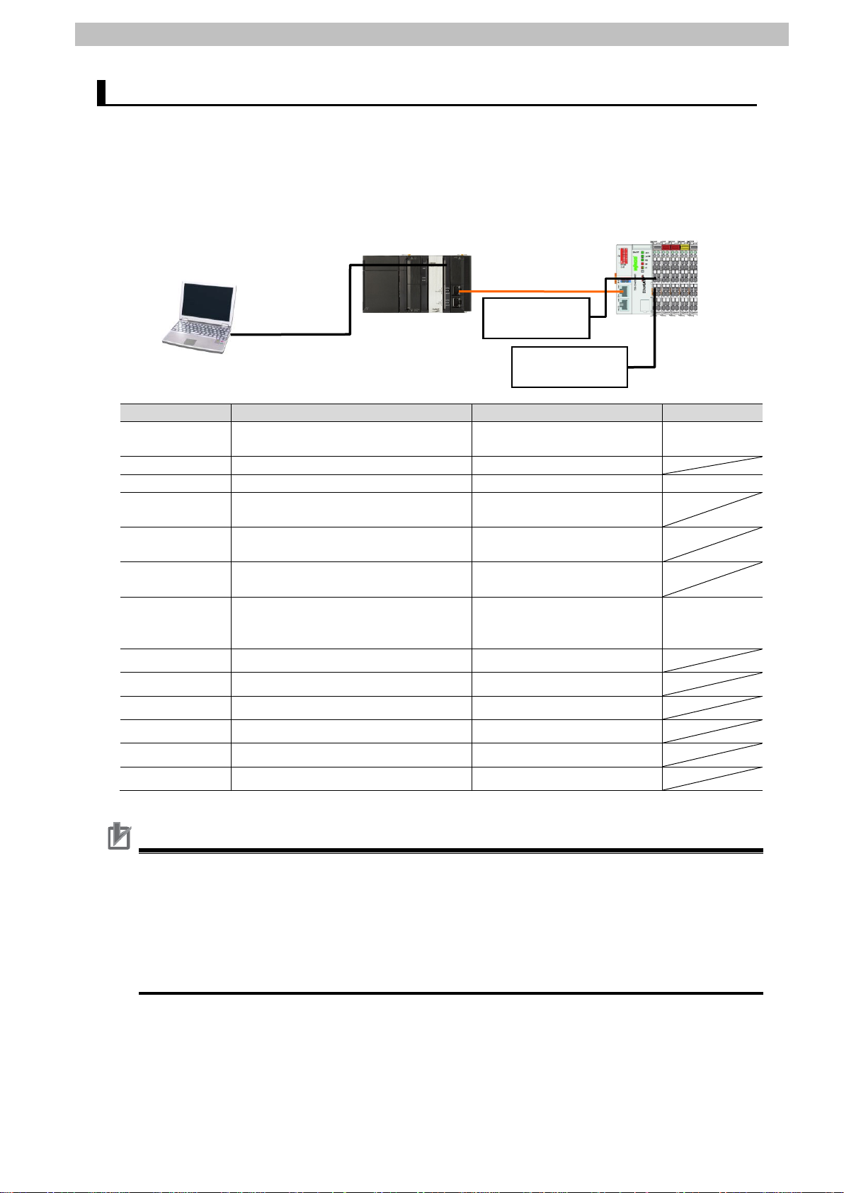
NJ501-1500
750-354/000-001+
Personal computer
24 VDC
24 VDC
power supply
5.2. Device Configuration
The hardware components to reproduce the connection procedure of this document are as
follows:
(Sysmac Studio installed,
OS: Windows 7)
(Built-in EtherCAT port)
Ethernet cable
750-602+750-501+
750-407+750-600
USB cable
power supply
-
-
Coupler with ID Address Selection
WAGO
WAGO
WAGO
WAGO End module
-
0x00010002
WAGO_750_354.xml
Prepare the ESI file shown in this section beforehand. The ESI file can be downloaded from
the WAGO website.
(WAGO
https://eshop.wago.com/JPBC/0_5StartPage.jsp?supplierAID=750-354%2F000-001&catalog
ID=WAGO01&zone=7)
Contact WAGO if the file is not available.
Page 9

5.Applicable Devices and Dev i ce Configuration
6
Precautions for Correct Use
Precautions for Correct Use
Additional Inf or mation
Additional Inf or mation
The connection line of EtherCAT communication cannot be shared with other Ethernet
networks.
Do not use devices for Ethernet such as a switching hub.
Use the cable (double shielding with aluminum tape and braiding) of Category 5 or higher,
and use the shielded connector of Category 5 or high er.
Connect the cable shield to the connector hood at both ends of the cable.
Update the S ysmac Studio to the version sp ec i fied in this s ection or hig her version using the
auto update function.
If a version not specified in this section is used, the procedures described in Section 7 and
subsequent sections may not be applic able. In that case, use the equivalent procedures
described in the Sysmac Studio Version 1 Operat io n M anual (Cat. No. W504).
For information on the specifications of the Ethernet cable and network wiring, refer to
Section 4 EtherCAT Network Wiring of the NJ-series CPU Unit Built-in Et herCAT Port User's
Manual (Cat. No. W505).
The system configuration in this document uses USB for the connection to the Controller.
For information on how to install a USB driver, refer to A-1 Driver Installation for Direct USB
Cable Connection of the Sysmac Studio V er s i on 1 Operation Manual (Cat. No. W504).
Page 10

6.EtherCAT Settings
7
Precautions for Correct Use
K-Bus Cycle Overrun
Flag Disable
Input Process Data Hold
Request
Output Process Data
Hold Request
Output Process Data
Clear Request
Diagnostics Control
Word
6. EtherCAT Settings
This section describes the specifications such as communication parameters and variables
that are set i n this document.
Hereinafter, the WAGO-I/O-SYSTEM Fieldbus Coupl er is referred t o as the "Destination
Device" or t he "Slave Unit" in some descr i ptions.
6.1. EtherCAT Communi cations Parameter Settings
The communications parameter required connecting the Controller and the Destination
Device via EtherCAT is given below.
WAGO-I/O-SYSTEM
Fieldbus Coupler
Node address 1
The Controller with the version described in this document cannot use the node address
setting with the rotary switches of the Destination Device. The node address for the
Destination Device can be set by Sysmac Studio.
6.2. Allocation for PDO Communications
The EtherCAT PDO communications data of the Destination Device are allocated to the
Controller's device variables. The device variables and the data types are shown below.
■ Output area (from Controller to Destination Device)
Device variable nam e Data type Meaning
E001_Output_K_Bus_Cycle_Overrun_Flag_Di_F200_01 BOOL
E001_Output_Input_Process_Data_Hold_Req_F200_02 BOOL
E001_Output_Output_Process_Data_Hold_Re_F200_03 BOOL
E001_Output_Output_Process_Data_Clear_R_F200_04 BOOL
E001_Output_Diagnostics_Control_Word_F200_05 UINT
M1_Output_s_Channel_1_Data_7000_01 BOOL
M1_Output_s_Channel_2_Data_7000_02 BOOL
M2_Output_s_Channel_1_Data_7000_01 BOOL
M2_Output_s_Channel_2_Data_7000_02 BOOL
Output of Digital Output
Module (Slot1)
Output of Digital Output
Module (Slot2)
Page 11

8
K-Bus Cycle Overrun
Flag
Input Process Data
Hold Acknowledge
Output Process Data
Hold Acknowledge
Output Process Data
Clear Acknowledge
Diagnostics History
Message Available
Diagnostics Status
Word
■ Input area (from Destination Device t o C ontroller)
Device variable nam e Data type Meaning
E001_Input_K_Bus_Cycle_Overrun_Flag_F100_01 BOOL
E001_Input_Input_Process_Data_Hold_Ack_F100_02 BOOL
E001_Input_Output_Process_Data_Hold_Ac_F100_03 BOOL
E001_Input_Output_Process_Data_Clear_A_F100_04 BOOL
E001_Input_New_Message_Available_10F3_04 BOOL
E001_Input_Diagnostics_Status_Word_F100_05 UINT
M3_Input_s_Channel_1_Data_6000_01 BOOL
M3_Input_s_Channel_2_Data_6000_02 BOOL
M3_Input_s_Channel_3_Data_6000_03 BOOL
M3_Input_s_Channel_4_Data_6000_04 BOOL
6.EtherCAT Settings
Input of Digital Input
Module (Slot3)
Page 12

7.EtherCAT Connection Procedure
9
7.2. Setting Up the WAGO-I/O-SYSTEM
Fieldbus Coupler
Set up the WAGO-I/O-SYSTEM Fieldbus Coupler.
↓
7.2.1. Hardware Settings
Set the hardware swi t ches o n th e
WAGO-I/O-SYSTEM Fieldbus Coupler.
↓
7.3. Setting Up the Controller
Set up the Controller.
↓
7.3.1. Starting the Sysmac Studio and
Installing the ESI File
Install the ESI file for the WAGO-I/O-SYSTEM
Fieldbus Coupler in the Sysmac Studio.
↓
7.3.2. Setting Up the EtherCAT
Network Configuration
Set up the EtherCAT network configuration.
↓
7.3.3. Setting the Device Variables
Set the device variables used for the EtherCAT
Slave Unit.
↓
7.3.4. Transferring the Projec t D ata
Transfer the project data from the Sysmac Studio to
the Controller.
↓
7.4. Checking the EtherCAT
Communications
Confirm that the PD O communications of EtherCAT
are performed normally.
↓
7.4.1. Checking the Connection Status
Check the connection status of the EtherCAT
network.
↓
7.4.2 Checking the Data that are Sent
and Receive d
Confirm that the correct data are sent and received.
7. EtherCAT Connection Procedure
This section describes the procedure for connecting the Controller to the WAGO-I/O-SYSTEM
Fieldbus Coupler via Et her CAT.
This document explains the procedures for setting up the Controller and the
WAGO-I/O-SYSTEM Fieldbus Coupler from the factory default setting.
For the initialization, refer to Section 8 Initialization Method.
7.1. Work Flow
Take the following steps to perform PDO communications of EtherCAT.
Page 13

7.EtherCAT Connection Procedure
10
following procedures.
4
Connect th e Ethernet cable to
5
Connect th e 24 VDC power
to the Field s upply.
Status LEDs
Fieldbus
Fieldbus connection
Digital output module
Fieldbus Coupler
Power supply module
Digital input module
Fieldbus connection
7.2. Setting Up the WAGO-I/O-SYSTEM Fieldbus Coupler
Set up the WAGO-I/O-SYSTEM Fieldbus Coupler.
7.2.1. Hardware Settings
Set the hardware swi t ches o n th e WAGO-I/O-SYSTEM Fieldbus Coupler.
Precautions for Correct Use
Make sure tha t t he power supply is OFF when you perform the set ting up.
Connect th e Power supply
1
module, Digi ta l in put module,
Digital output module, and End
module to the Fieldbus Coupler
so that the WAGO-I/O-SYSTEM
is created.
In this document, two sets of
2-channel dig i tal output modules
and one 4-c hannel digital input
module are c onnected as an I/O
Unit as shown on the right.
* If the power supply is turn ed
ON, settings may not be
applicable as described in the
System supply
Field supply
End module
Check the position of the
2
hardware switches on the front
panel of the
WAGO-I/O-SYSTEM Fieldbus
Coupler by referring to the right
figure.
Set all the Address Selection
3
Switches to OFF.
* The actual node address is set
by Sysmac Studio.
the Fieldbus connection (X1 IN).
supply to the System supply and
Address Selection
Switch
(X1 IN)
(X1 OUT)
Page 14
7.EtherCAT Connection Procedure
11
End Cover
Power Supply Unit
Ethernet
cable
CPU Unit
Controller
7.3. Setting Up the Controller
Set up the Controller.
7.3.1. Starting the Sysmac Studio and Installing the ESI File
Install the ESI file for the WAGO-I/O-SYSTEM Fieldb us Coupler in the Sysmac Studio.
Install the Sysmac Studio and USB driver in the Personal computer beforehand.
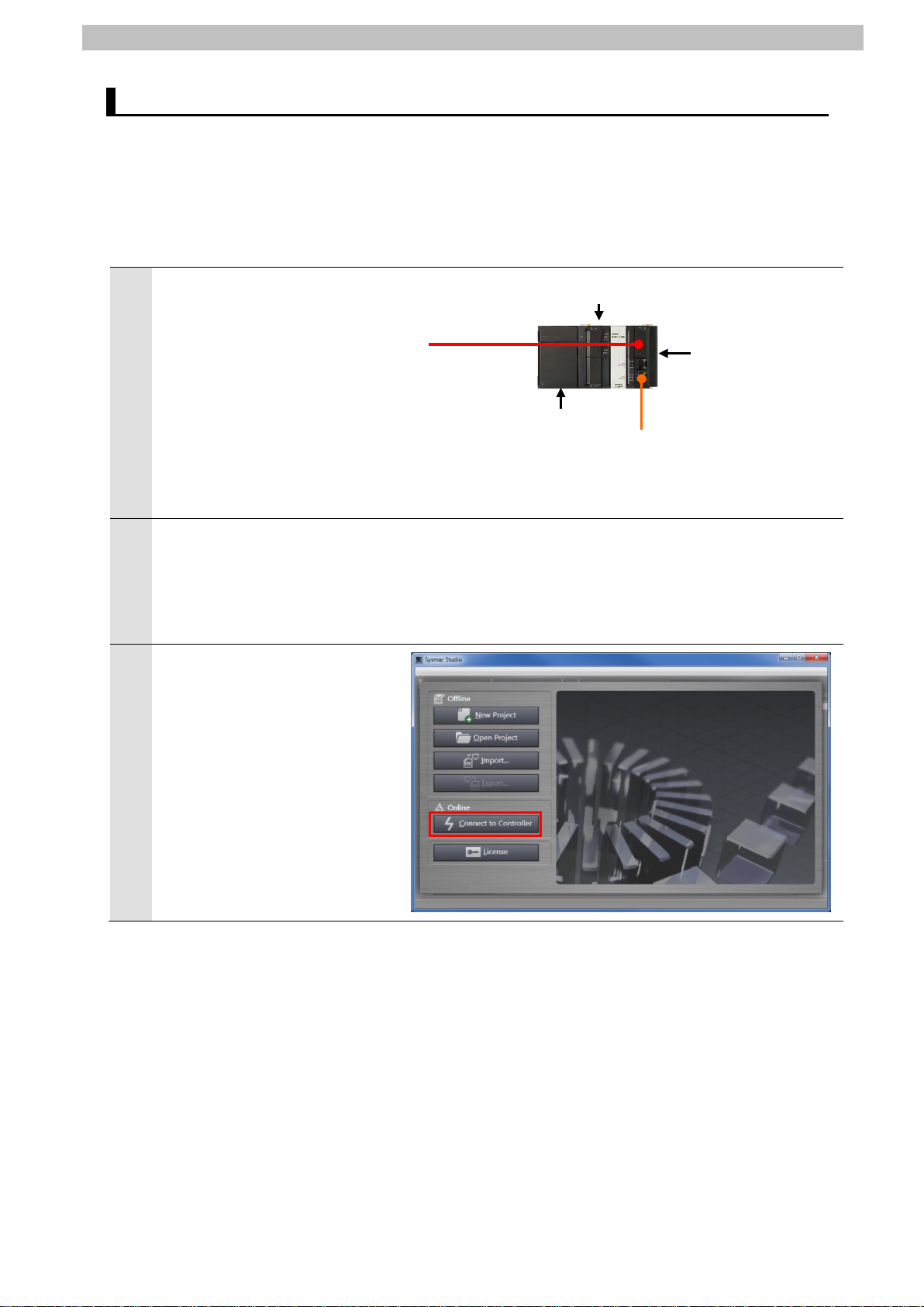
Connect the Ethernet cable to
1
the built-in EtherCAT port
(PORT2) of the Controller and
connect the USB cable t o the
peripher al ( U SB) port.
As shown in 5.2. Device
Configuration, connect the
Personal computer,
WAGO-I/O-SYSTEM Fieldbus
Coupler, and Controller.
Turn ON the power supply to the
2
Controller and the System
supply and the Field supply to
the WAGO-I/O-SYSTEM
Fieldbus Coupler.
Start the Sysmac Studio.
3
Click the Connect to Controller
Button.
* If a confirmation dialog for an
access right is displayed at
start, se lect to sta rt.
USB cable
Page 15

12
The Connect to Controller
Click the Connect Button.
proceed with the processi ng.
Additional Inf or mation
Status
Plane
Multiview
Explorer
Edit Pane
Toolbox
4
Dialog Box is displayed.
Select the Direct connect i on via
USB Option for Connection
type.
Uncheck both of the Upload the
project Check Box and the
Display the T r oubl esh ooting
Dialog Box Check Box of
Operation after Connection.
7.EtherCAT Connect i on Pr ocedure
A con firmation dialog box on the
5
right is displayed. Check t he
contents and click the OK
Button.
* The displayed dialog depends
on the status of the Controller
used. Check the contents and
click the Yes or OK Button to
A confirmation dialog box is
6
displayed. Check the contents
and click the OK Button.
The A ut o C onnect Project
7
Dialog Box is displayed online.
When an online connection is
established, a yellow bar is
displayed on the Pane.
The left pane is called Multiview
Explorer, the top right pane is
called Toolbox, the bottom r ight
pane is called Status Monitor
Plane, and the middle pane is
called Edit Pane.
Monitor
For details on online conn ect ions to a Controller, refer to Section 5 Online Connections to a
Controller of the Sysmac Studio Vers i on 1 O peration Manual (Cat. No. W504).
Page 16

13
10
Double-click EtherCAT under
8
Configurations and Setup in
the Multiview Explorer.
The EtherCAT Tab is displayed
9
on the Edit Pane.
Right-click Master and select
Display ESI Library.
7.EtherCAT Connect i on Pr ocedure
The ESI Library Dialog Box is
11
displayed. Click the this folder
link.
When the Explorer starts, close
the dialog box by clicking t he
Close Button.
The Explorer starts and a fo lder
12
is opened, allowing you to inst al l
the ESI file. Copy the prep ar ed
WAGO_750_354.xml to this
folder.
Page 17

14
Select Exit from the File Menu
Close
Precautions for Correct Use
13
to exit the Sysmac Studio.
A dialog box is displayed
confirming whether to save the
project. If you do not need to
save it, click the No Button.
* You need to restart the
Sysmac Studio after instal lin g
the ESI file.
7.EtherCAT Connect i on Pr ocedure
In the same way as steps 3 to
14
10, restart the Sysmac Studio
and display the ESI Librar y
Dialog Box.
Click the + Button of
WAGO_750_354 to confirm that
750-354/000-001
Rev:0x00010002(750-354/000001 EtherCAT fieldbus coupler)
device is displayed.
Confirm that an exclamation
mark (warning) is not disp l ayed.
Click the
Button
If an exclamation mark (war ning) is displayed for the ESI file, c heck the name of the ESI file
and obtain the ESI file wit h a cor r ect name. If an exclamation mark (warning) is displayed
even when the name of the ESI fil e is correct, the file may be corru pted. Contact the device
manufacturer.
Page 18

7.EtherCAT Connect i on Pr ocedure
15
7.3.2. Setting Up the EtherCAT Network Configuration
Set up the EtherCAT network configuration.
Confirm that a yellow bar is
1
displayed on the top of the Ed it
Pane which indicates an online
connection is established.
Right-click Master on the
2
EtherCAT Tab Page of the Edit
Pane, and select Wri t e Slave
Node Address.
* If the EtherCAT Tab Page is
not displayed on the Edit Pane,
display it by following step 8 of
7.3.1. Starting the Sysmac
Studio and Installing the ESI
File.
A screen is displayed stating
"Get information is being
executed".
The Slave Node Address W rit ing
3
Dialog Box is displayed.
The present value (setting node
address) and 750-354/000-001
Rev:0x00010002 are displayed
in the Actual network
configuration.
* If the present value of the node
address is 0, an error is
displayed.
Enter 1 in the Set value Fi eld for
4
a node address.
Page 19

16
Confirm that there is no error in
Close Button.
configuration
5
the set value and 1 is set.
Click the Write Button.
The Slave Node Address W rit ing
6
Dialog Box is displayed.
Click the Write Button.
Then, a screen is displayed
stating "Writing no de addresses
to slaves was successfully
completed".
Check the contents and c l ick the
7.EtherCAT Connect i on Pr ocedure
Cycle the power supply to t he
7
Slave Unit.
The EtherCAT Tab Page is
8
displayed again. Right-click
Master and select Compare
and Merge with Actual
Network Configuration.
A screen is displayed stating
"Get information is being
executed".
The Compare and Merge with
9
Actual Network Configur ation
Dialog Box is displayed.
Node address 1 and
750-354/000-001
Rev:0x00010002 are add ed t o
the Act ual network configuration
after the comparison.
Click the Apply actual network
Button.
Page 20
17
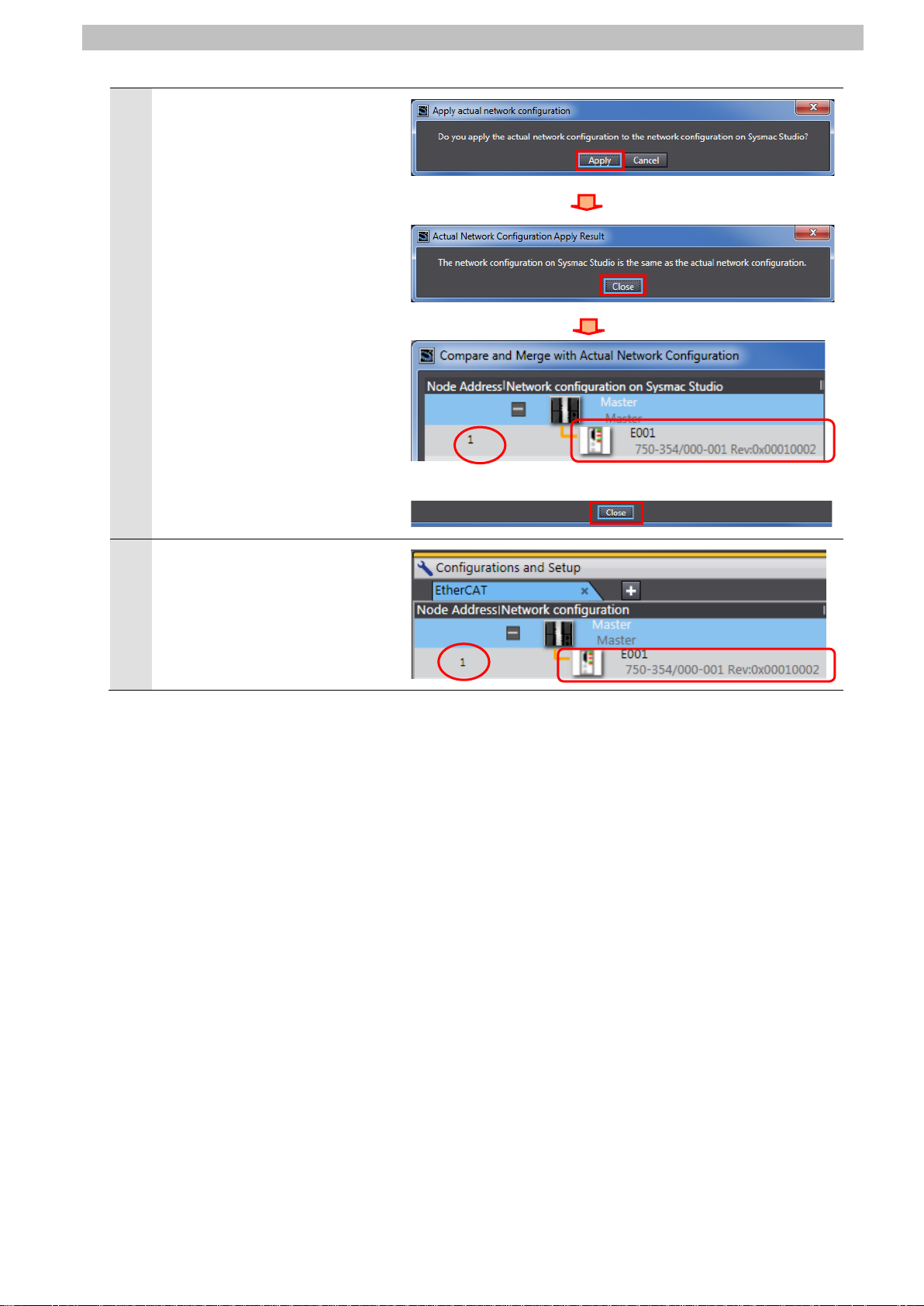
A con firmation dialog box on the
10
right is displayed.
Check the contents and c l ick the
Apply Button.
A result confirmation dialog box
is displayed.
Click the Close Button.
Node address 1, E001 an d
750-354/000-001
Rev:0x00010002 are add ed t o
the Network configuratio n on
Sysmac Studio.
Confirm that the data abo ve are
added and click the Close
Button.
Node address 1, E001, and
11
750-354/000-001
Rev:0x00010002 are add ed t o
the EtherCAT Tab Page on the
Edit Pane.
7.EtherCAT Connect i on Pr ocedure
Page 21

18
7.3.3. Setting the Device Variables
Configuration Button.
Set the device variables us ed f or t he Et herCAT Slave Unit.
Select Offline from the
1
Controller Menu.
The yellow bar on the top of the
Edit Pane disappears.
Select 750-354/000-001
2
Rev:0x00010002 set in the
previous steps in the EtherCAT
Tab Page and confirm that
Device name is E001.
* Device name can be cha nged
as desired.
Click the Edit Module
7.EtherCAT Connect i on Pr ocedure
The Node1:
3
750-354/000-001(E0 01) Tab
Page is displayed.
Select each configured m odule
in order and confirm that Device
name is as follows:
・750-5xx / 750-15xx
(2b out)(M1) : M1
・750-5xx / 750-15xx
(2b out)(M2) : M2
・750-4xx / 750-14xx
(4b in)(M3) : M3
* Device name can be cha nged
as desired.
* The device name you s et is
used at the beginning of the
device variables.
Page 22

19
Double-click I/O Map under
4
Configurations and Setup in
the Multiview Explorer.
The I/O Map Tab is displayed on
5
the Edit Pane.
Confirm that Node1 is dis played
in the Position Column and the
Slave Unit is displayed.
* To manually set a variable
name for the Slave Unit, click a
column under the Variable
Column and enter a name.
7.EtherCAT Connect i on Pr ocedure
Right-click Node1 and select
6
Create Device Varia ble.
The variable names and
7
variable types are automa t ical ly
set.
Page 23

20
Additional Inf or mation
Additional Inf or mation
The device variables are named automatically from a com bination of the device names and
the port names.
The default device names ar e “ E" fo llowed by a serial number that star t s from 001.
For Slave Units with module configurations, the de fa ult device names start with an "M"
followed by a sequential n um ber st ar t ing from "1".
In this document, device var iab les are automatically named for a unit (a slave). Device
variables can also be manual ly nam ed for I/O ports.
7.EtherCAT Connect i on Pr ocedure
Page 24

7.EtherCAT Connect i on Pr ocedure
21
behave according to the sl ave sett ings. The ti me that communicat ions are c ut of f
Before you transfer the user pr ogr am, confirm that it will not adv er sely affect the
3
7.3.4. Transferring the Project Data
Transfer t he pr oject data from the Sysmac Stu dio t o the Controller.
Always confirm safety at the Des t in ation Device before you t r ansfer a user
program, configuration d ata, setup data, device variables, or values in memory
used for CJ-series Units from the Sysmac Studio.
The devices or machines may perform unexpected operation regardless of the
operating mode of the CPU U nit.
After you transfer the user pr ogr am, the CPU Unit restarts and co m m uni cat ions
with the EtherCAT slaves are cut off. During t hat period, the slave outputs
depends on the EtherCAT network configurat i on.
device.
Select Check All Programs
1
from the Project Menu.
The Build Tab Page is displayed
2
on the Edit Pane.
Confirm that "0 Errors" an d "0
Warnings" ar e di s played.
Select Rebuild Controller from
the Project Menu.
A con firmation dialog box on the
4
right is displayed. Confir m t hat
there is no problem and cl ick the
Yes Button.
Page 25

22
Confirm that "0 Errors" an d "0
5
Warnings" ar e di s played in the
Build Tab Page.
Select Online from the
6
Controller Menu.
Select Synchronization from
7
the Controller Menu.
7.EtherCAT Connect i on Pr ocedure
The Synchronization Dialog Box
8
is displayed.
Confirm that the data to transfer
(NJ501 in the right dialog) is
selected. Then, cli ck the
Transfer To Controller Button.
* After executing the Tr ansfer To
Controller, the Sysmac Studio
data is transferred to the
Controller and the data is
compared.
Page 26

23
A con firmation dialog box on the
9
right is displayed. Confir m t hat
there is no problem and cl ick the
Yes Button.
A screen stating "Synchronizing"
is displayed.
A con firmation dialog box on the
right is displayed. Confir m t hat
there is no problem and click the
No Button.
* Do not return it to RUN mode.
7.EtherCAT Connect i on Pr ocedure
Confirm that the synchron ized
10
data is displayed with the color
specified by "Synchronized"
and that a message is displayed
stating "The synchronizat ion
process successfully fini shed".
If there is no problem, click the
Close Button.
* A message stating "The
synchronization process
successfully finished" is
displayed if the Sysmac Studio
project data and the data in the
Controller match.
* If the synchronization fails,
check the wiring and repe at
from step 1.
Page 27

7.EtherCAT Connect i on Pr ocedure
24
Label
Name
Color
Status
Meaning
EtherCAT
NET RUN
EtherCAT communications are in progress
operation
EtherCAT
NET ERR
LINK/ACT
Activity
Data communications are in progress after
Flashes every time data is sent or received
Name
LED Status
Meaning
A connection from the EtherCATR connection to
via this interface.
RUN
(Green)
ERR
(Red)
7.4. Checking the EtherCAT Communications
Confirm that the PDO com m uni c at i ons of EtherCAT are performed normally.
7.4.1. Checking the Connection Status
Check the connection status of the EtherCAT network.
Confirm that the EtherC AT
1
communications are per fo r me d
normally by checking the LED
indicators on the Controlle r.
The LED indicators in nor ma l st at us
are as follows:
[NET RUN]: Lit green
[NET ERR]: Not lit
[LINK/ACT]: Flashing y el l ow
EtherCAT
RUN
ERROR
Link/
■
Green
■
Not lit There are no errors
Red
■
Flashing
Yellow
Lit
Inputs and outputs for I/O data are in
establishing link
Check the LED indicators on t he
2
WAGO-I/O-SYSTEM Fieldbus
Coupler.
The LED indicators in normal status
are as follows:
[L/A IN]: Flashing green
[RUN]: Lit green
[ERR]: Not lit
L/A IN
L/A OUT
Flashing
(Green)
ON The fieldbus coupler is in the OP state.
OFF The fieldbus node is ready for operation.
another EtherCATR participant was determined for
the respective interface. Data is being exchanged
Page 28

7.EtherCAT Connect i on Pr ocedure
25
Sufficiently confir m safety before y ou chang e the v alues of var iable s on a Watch
If you proceed to this section, ma ke sure to complete all the steps and place the
1
3
7.4.2. Checking the Data that are Sent and Received
Confirm that the correct d at a ar e s ent and received.
Tab Page when the Sysmac Studio is on lin e w ith the CPU Unit.
The devices that are conn ect ed t o out put units may operate regar dless of the
operating mode of the Contr oller.
The Destination Device wi ll run if you proceed to this section. Confirm safety
before operation. If you cannot confirm safety, do not proceed to this section
after completing until Section 7.4.1.
Destination Device in the safe state.
Select Watch Tab Page from the
View Menu.
The Watch1 Tab Page is displayed
2
in the lower section of the Edit
Pane.
Enter the following names in the
Watch1 Tab Page f or m onitoring.
Click a column under the Name
Column to enter a new name.
M1_Output_s_Channel_1_Data_
7000_01
M2_Output_s_Channel_1_Data_
7000_01
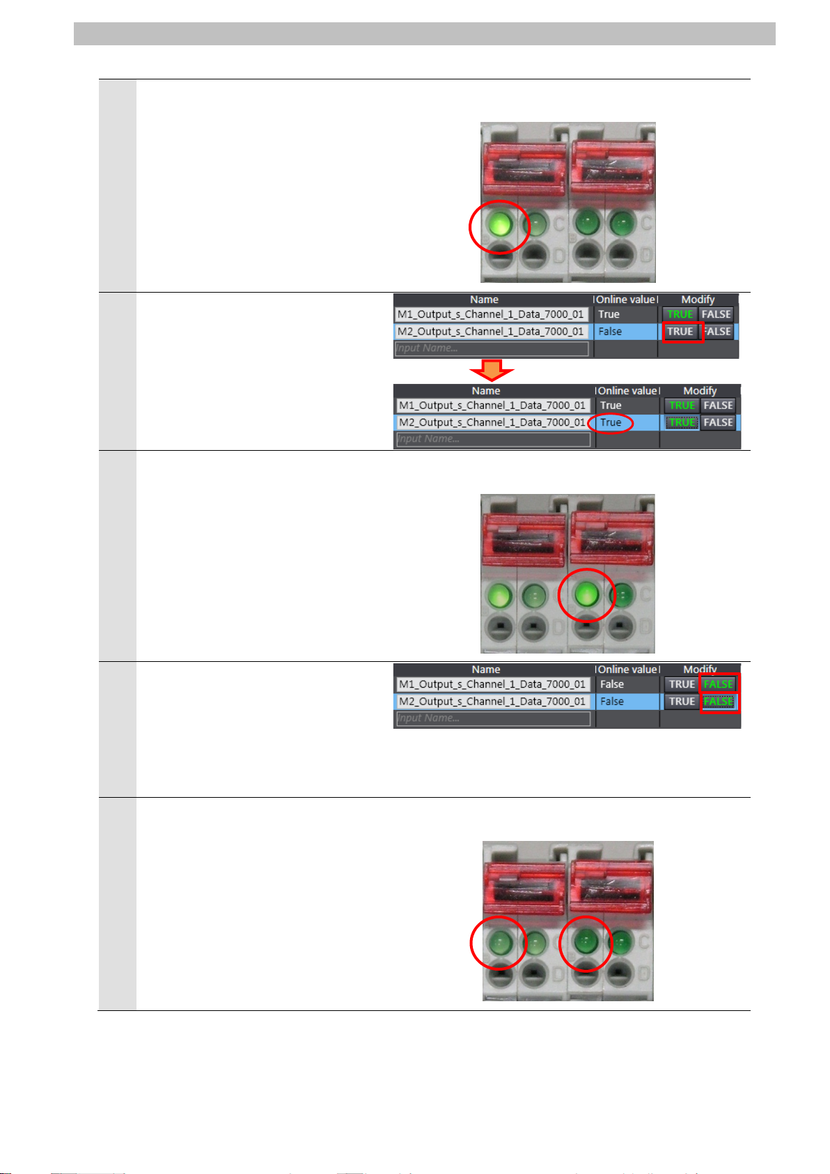
Click TRUE in the Modify Column of
4
M1_Output_s_Channel_1_Data_70
00_01.
The Online value of
M1_Output_s_Channel_1_Data_70
00_01 changes to Tr ue.
Page 29
7.EtherCAT Connect i on Pr ocedure
26
Digital Output
Slot1(M1)
Digital Output
Slot2(M2)
Digital Output
Slot1(M1)
Digital Output
Slot2(M2)
Digital Output
Slot1(M1)
Digital Output
Slot2(M2)
Confirm that the bit corresponds to
5
the Digital Output Module Sl ot 1
(M1), which is connected to the
Fieldbus Coupler, is turned ON and
its LED indicator is lit.
In the same way, click TRUE in the
6
Modify Column of
M2_Output_s_Channel_1_Data_70
00_01.
The Online value changes to True.
Confirm that the bit corresponds to
7
the Digital Output Module Sl ot 2
(M2), which is connected to the
Fieldbus Coupler, is turned ON and
its LED indicator is lit.
Module
Module
Module
Module
Click FALSE in the Modify Columns
8
of
M1_Output_s_Channel_1_Data_70
00_01 and
M2_Output_s_Channel_1_Data_70
00_01.
Confirm that the bits corres pond to
9
Slot1 (M1) and Slot2 (M2) of the
Digital Output Modules are turned
OFF and their LED indicator s do not
light.
Module
Module
Page 30

8.Initialization Method
27
8. Initialization Method
This document explains the s et t ing procedure from the factory default setting.
Some settings may not be appl icable as described in this docu me nt unless you use the
devices with the factory d efault setting.
8.1. Initializing the Controller
To initialize the settings of the Control ler, select Clear All Memory from the Controller Menu of
the Sysmac Studio. The Clear All Memory Dialog Box is displ ayed. Check the contents a nd
click the OK Button.
Page 31

28
9. Revision History
code
Revision
01 Apr. 9, 2014 First edition
Date of revision Revision reaso n and revision page
9.Revision History
Page 32

2014
P594-E1-01
0414(-)
 Loading...