

Page 1
Cat. No.
TOEPC71067605-03-OY
VARISPEED L7
The frequency inverter for the lifts
USER´S MANUAL
Page 2

Table of Contents
Warnings .......................................................................................................VII
Safety Precautions and Instructions ............................................................ VIII
EMC Compatibility ......................................................................................... X
Line Filters ....................................................................................................XII
Registered Trademarks ............................................................................... XIII
1 Handling Inverters ................................................................. 1-1
Varispeed L7 Models ...................................................................................1-2
Confirmations upon Delivery .......................................................................1-3
Checks ...........................................................................................................................1-3
Nameplate Information ..................................................................................................1-3
Inverter Software Version ..............................................................................................1-4
Component Names ........................................................................................................1-5
Exterior and Mounting Dimensions ..............................................................1-7
IP00 Inverters ................................................................................................................1-7
IP20 / NEMA 1 Inverters ................................................................................................1-7
Checking and Controlling the Installation Site .............................................1-9
Installation Site ..............................................................................................................1-9
Controlling the Ambient Temperature ............................................................................1-9
Protecting the Inverter from Foreign Matter ...................................................................1-9
Installation Orientation and Space .............................................................1-10
Removing and Attaching the Terminal Cover ............................................ 1-11
Removing the Terminal Cover ..................................................................................... 1-11
Attaching the Terminal Cover .......................................................................................1-12
Removing/Attaching the Digital Operator/
LED Monitor and Front Cover ....................................................................1-13
Inverters of 18.5 kW or Less ........................................................................................1-13
Inverters of 22 kW or More ..........................................................................................1-15
2 Wiring ...................................................................................... 2-1
Connection Diagram ....................................................................................2-2
Circuit Descriptions ........................................................................................................2-3
Terminal Block Configuration .......................................................................2-4
I
Page 3

Wiring Main Circuit Terminals ......................................................................2-5
Applicable Wire Sizes and Crimp Terminals .................................................................. 2-5
Main Circuit Terminal Functions .................................................................................... 2-9
Main Circuit Configurations ......................................................................................... 2-10
Standard Connection Diagrams .................................................................................. 2-11
Wiring the Main Circuits .............................................................................................. 2-12
Wiring Control Circuit Terminals ................................................................ 2-17
Wire Sizes ................................................................................................................... 2-17
Control Circuit Terminal Functions .............................................................................. 2-18
Control Circuit Terminal Connections .......................................................................... 2-20
EN81-1 Conform Wiring with One Motor Contactor ..................................2-21
Control Circuit Wiring Precautions .............................................................................. 2-22
Wiring Check .............................................................................................2-23
Checks ........................................................................................................................ 2-23
Installing and Wiring Option Cards ............................................................ 2-24
Option Card Models and Specifications ...................................................................... 2-24
Installation ...................................................................................................................2-24
PG Speed Control Card Terminals and Specifications ................................................ 2-25
Wiring the Terminal Blocks ......................................................................................... 2-31
3 LED Monitor / Digital Operator and Modes ..........................3-1
LED Monitor JVOP-163 ............................................................................... 3-2
LED Monitor .................................................................................................................. 3-2
LED Display Examples .................................................................................................. 3-2
Digital Operator JVOP-160-OY ...................................................................3-3
Digital Operator Display ................................................................................................ 3-3
Digital Operator Keys .................................................................................................... 3-3
Inverter Modes ..............................................................................................................3-5
Switching Modes ........................................................................................................... 3-6
Drive Mode ....................................................................................................................3-7
Quick Programming Mode ............................................................................................. 3-8
Advanced Programming Mode ...................................................................................... 3-9
Verify Mode ................................................................................................................. 3-11
Autotuning Mode ......................................................................................................... 3-12
4 Start Up Procedure .................................................................4-1
General Start Up Routine ............................................................................4-2
Start Up ......................................................................................................................... 4-2
II
Power Up .................................................................................................... 4-3
Before Power Up ........................................................................................................... 4-3
Display after Power Up .................................................................................................. 4-3
Control Mode Selection ................................................................................................. 4-3
Autotuning ...................................................................................................4-4
Page 4

Autotuning Mode Selection ............................................................................................4-4
Auto Tuning Precautions ...............................................................................................4-5
Autotuning Procedure with Induction Motors .................................................................4-6
Autotuning Procedure with PM Motors ..........................................................................4-7
PM Motor Encoder Offset Tuning ..................................................................................4-8
Precautions for Induction Motor Autotuning ...................................................................4-9
Autotuning Alarms and Faults ......................................................................................4-10
Performance Optimization ......................................................................... 4-11
5 User Parameters .................................................................... 5-1
User Parameter Descriptions ......................................................................5-2
Description of User Parameter Tables ...........................................................................5-2
Digital Operation Display Functions and Levels ..........................................5-3
User Parameters Available in Quick Programming Mode .............................................5-4
User Parameter Tables ................................................................................5-8
Setup Settings: A ...........................................................................................................5-8
Application Parameters: b ............................................................................................5-10
Tuning Parameters: C ..................................................................................................5-12
Reference Parameters: d .............................................................................................5-18
Motor Parameters: E ....................................................................................................5-21
Option Parameters: F ..................................................................................................5-26
Terminal Function Parameters: H ................................................................................5-32
Protection Function Parameters: L ..............................................................................5-37
Special Adjustments: n2 / n5 .......................................................................................5-43
PM Motor Adjustments: n8 / n9 ...................................................................................5-44
Digital Operator/LED Monitor Parameters: o ...............................................................5-45
Lift Function Parameters: S .........................................................................................5-47
Motor Autotuning: T .....................................................................................................5-53
Monitor Parameters: U .................................................................................................5-55
Settings which change with the Control Mode (A1-02) ................................................5-61
Factory Settings Changing with Inverter Capacity (o2-04) ..........................................5-63
6 Parameter Settings by Function ........................................... 6-1
Carrier Frequency Derating and
Current Limitation ........................................................................................6-2
Carrier Frequency Setting ..............................................................................................6-2
Current limitation level at low speeds ............................................................................6-2
Control / Brake Sequence ...........................................................................6-3
Up and Down Commands ..............................................................................................6-3
Speed Reference Source Selection ...............................................................................6-4
Speed Selection Sequence Using Digital Inputs ...........................................................6-5
Emergency Stop ..........................................................................................................6-10
Inspection RUN ............................................................................................................6-11
Brake Sequence ..........................................................................................................6-13
Short Floor Operation ..................................................................................................6-17
III
Page 5

Acceleration and Deceleration Characteristics .........................................6-20
Setting Acceleration and Deceleration Times .............................................................. 6-20
Acceleration and S-curve Settings .............................................................................. 6-22
Output Speed Hold (Dwell Function) ........................................................................... 6-22
Stall Prevention During Acceleration ........................................................................... 6-23
Adjusting Analog Input Signals ................................................................. 6-25
Adjusting Analog Frequency References .................................................................... 6-25
Speed Detection and Speed Limitation .....................................................6-26
Speed Agreement Function ......................................................................................... 6-26
Limiting the Elevator Speed to the Leveling Speed (d1-17) ........................................ 6-28
Improving the Operation Performance ......................................................6-29
Reducing the Motor Speed Fluctuation (Slip Compensation Function) ....................... 6-29
Torque Compensation Function Adjustments .............................................................. 6-30
Starting Torque Compensation Function (C4-03 to C4-05) ......................................... 6-32
Automatic Speed Regulator (ASR) (Closed Loop Vector only) ................................... 6-32
Stabilizing Speed (Automatic Frequency Regulator) (Open Loop Vector) ...................6-34
Inertia Compensation (Closed Loop Vector Only) ....................................................... 6-35
Automatic Current Regulator (ACR) Tuning ................................................................ 6-36
A/D Conversion Delay Time Tuning ............................................................................ 6-37
Improving the Leveling Accuracy by Leveling Speed Slip Compensation ................... 6-37
Field Forcing ................................................................................................................ 6-38
Adjusting the DC Injection Current .............................................................................. 6-39
Adjusting the DC Injection Current Levels (S1-02/03) ................................................. 6-39
Protective Functions .................................................................................. 6-40
Preventing Motor Stalling During Operation ................................................................ 6-40
Motor Torque Detection / Car Stuck Detection ............................................................ 6-40
Limiting the Motor Torque (Torque Limit Function) ...................................................... 6-43
Motor Overload Protection .......................................................................................... 6-44
Output Current Observation ........................................................................................ 6-46
Over Acceleration Detection (“DV6” Fault Detection) .................................................. 6-46
Inverter Protection .....................................................................................6-47
Inverter Overheat Protection ....................................................................................... 6-47
Input Open Phase Protection* ..................................................................................... 6-47
Output Open Phase Detection .................................................................................... 6-48
Ground Fault Detection ............................................................................................... 6-48
Cooling Fan Control .................................................................................................... 6-49
Setting the Ambient Temperature ................................................................................ 6-49
Input Terminal Functions ...........................................................................6-50
Disable the Inverter Output (Baseblock) ..................................................................... 6-50
Stopping the Inverter on External Device Errors (External Fault Function) ................. 6-51
Using the Timer Function ............................................................................................ 6-52
Motor Contactor Answer Back Detection ..................................................................... 6-53
Changing the PG direction .......................................................................................... 6-54
Motor 2 Selection ........................................................................................................ 6-55
IV
Page 6

Output Terminal Functions .........................................................................6-56
Motor and V/f Pattern Setup ......................................................................6-59
Setting Motor Parameters for Induction Motors (Motor 1 and 2) .................................6-59
Setting Motor Parameters for PM Motors ....................................................................6-62
Motor Rotation Direction Change ................................................................................6-63
Digital Operator/LED Monitor Functions ....................................................6-64
Setting Digital Operator/LED Monitor Functions ..........................................................6-64
Copying Parameters (JVOP-160-OY only) ..................................................................6-66
Prohibiting Overwriting of Parameters .........................................................................6-70
Setting a Password ......................................................................................................6-70
Displaying User-set Parameters Only ..........................................................................6-71
PG Option Cards .......................................................................................6-72
PG Setup .....................................................................................................................6-72
Fault Detection .............................................................................................................6-74
Machine Data Copy Function ......................................................................................6-75
Rescue System .........................................................................................6-77
Automatic Fault Reset ...............................................................................6-81
Memobus Communications .......................................................................6-83
MEMOBUS Communications Configuration ................................................................6-83
Message Content .........................................................................................................6-83
Inverter Error Codes ....................................................................................................6-92
ENTER Command .......................................................................................................6-92
Communication Error Codes .......................................................................................6-93
7 Troubleshooting .................................................................... 7-1
Protective and Diagnostic Functions ...........................................................7-2
Fault Detection ...............................................................................................................7-2
Alarm Detection .............................................................................................................7-9
Operator Programming Errors .....................................................................................7-12
Auto-tuning Faults .......................................................................................................7-14
Digital Operator Copy Function Faults .........................................................................7-16
Machine Data Copy Function Faults ............................................................................7-17
Troubleshooting .........................................................................................7-18
If A Parameter Cannot Be Set .....................................................................................7-18
If the Motor Does Not Operate Properly ......................................................................7-19
If the Direction of the Motor Rotation is Reversed .......................................................7-19
If the Motor Stalls or Acceleration is Slow ....................................................................7-19
If Motor Deceleration is Slow .......................................................................................7-20
Motor torque is insufficient. ..........................................................................................7-20
If the Motor Overheats .................................................................................................7-20
If Peripheral Devices are Influenced by the Starting or Running Inverter ....................7-21
If the Earth Leakage Breaker Operates When the Inverter is Running .......................7-21
If There is Mechanical Oscillation ................................................................................7-21
V
Page 7

8 Maintenance and Inspection .................................................8-1
Maintenance and Inspection ....................................................................... 8-2
Periodic Inspection ........................................................................................................ 8-2
Periodic Maintenance of Parts ...................................................................................... 8-3
Cooling Fan Replacement ............................................................................................. 8-4
Removing and Mounting the Terminal Card .................................................................. 8-6
9 Specifications .........................................................................9-1
Inverter Specifications .................................................................................9-2
Specifications by Model ................................................................................................. 9-2
Common Specifications ................................................................................................. 9-4
Derating .......................................................................................................9-6
Ambient Temperature Derating ..................................................................................... 9-6
Carrier Frequency Derating ........................................................................................... 9-6
Altitude Derating ............................................................................................................ 9-7
AC Reactors for EN 12015 Compatibility ....................................................9-8
EN 954-1 / EN81-1 Certificates ...................................................................9-9
10 Appendix ...............................................................................10-1
Inverter Application Precautions ...............................................................10-2
Selection ...................................................................................................................... 10-2
Installation ................................................................................................................... 10-2
Settings ....................................................................................................................... 10-2
Handling ......................................................................................................................10-3
Motor Application Precautions ..................................................................10-4
Using the Inverter for an Existing Standard Motor ....................................................... 10-4
Using the Inverter for Special Motors .......................................................................... 10-4
User Constants ..........................................................................................10-5
VI
Page 8

Warnings
Cables must not be connected or disconnected, nor signal tests carried out, while the power is
switched on.
The Varispeed L7 DC bus capacitor remains charged even after the power has been switched off. To
avoid an electric shock hazard, disconnect the frequency inverter from the mains before carrying out
maintenance. Then wait for at least 5 minutes after all LEDs have gone out.
Do not perform a withstand voltage test on any part of the inverter. It contains semiconductors,
which are not designed for such high voltages.
Do not remove the digital operator while the mains supply is switched on. The printed circuit board
must also not be touched while the inverter is connected to the power.
Never connect general LC/RC interference suppression filters, capacitors or overvoltage protection devices to
the inverter input or output.
CAUTION
To avoid unnecessary over current faults, etc., being displayed, the signaling contacts of any contactor or switch fitted between inverter and motor must be integrated into the inverter control logic
(e.g. baseblock).
This is absolutely imperative!
This manual must be read thoroughly before connecting and operating the inverter. All safety precautions and instructions for use must be followed.
The inverter must be operated with the appropriate line filters, following the installation instructions
in this manual and with all covers closed and terminals covered.
Only then will adequate protection be provided. Please do not connect or operate any equipment
with visible damage or missing parts. The operating company is responsible for any injuries or
equipment damage resulting from failure to heed the warnings in this manual.
VII
Page 9

Safety Precautions and Instructions
1. General
Please read these safety precautions and instructions for use thoroughly before installing and operating this
inverter. Also read all of the warning signs on the inverter and ensure they are never damaged or removed.
Live and hot inverter components may be accessible during operation. Removal of housing components, the
digital operator or terminal covers runs the risk of serious injuries or damage in the event of incorrect installation or operation. The fact that frequency inverters control rotating mechanical machine components can give
rise to other dangers.
The instructions in this manual must be followed. Installation, operation and maintenance may only be carried
out by qualified personnel. For the purposes of the safety precautions, qualified personnel are defined as individuals who are familiar with the installation, starting, operation and maintenance of frequency inverters and
have the proper qualifications for this work. Safe operation of these units is only possible if they are used
properly for their intended purpose.
The DC bus capacitors can remain live for about 5 minutes after the inverter is disconnected from the power. It
is therefore necessary to wait for this time before opening its covers. All of the main circuit terminals may still
carry dangerous voltages.
Children and other unauthorized persons must not be allowed access to these inverters.
Keep these Safety Precautions and Instructions for Use readily accessible and supply them to all persons with
any form of access to the inverters.
2. Intended Use
Frequency inverters are intended for installation in electrical systems or machines. The systems and machines
must be correspondent wiht the relevant directives and standards. Relevant guidelines like Low Voltage Directives , Machinery Directives , Emc Directives and other s are to be kept.
The Inverters may be put into operation, when the systems and machines in whitch they are inrested to the
guidelines and laws correspondent.
CE marking is carried out to EN 50178, using the line filters specified in this manual and following the appropriate installation instructions.
3. Transportation and storage
The instructions for transportation, storage and proper handling must be followed in accordance with the technical data.
4. Installation
Install and cool the inverters as specified in the documentation. The cooling air must flow in the specified
direction. The inverter may therefore only be operated in the specified position (e.g. upright). Maintain the
specified clearances. Protect the inverters against impermissible loads. Components must not be bent nor insulation clearances changed. To avoid damage being caused by static electricity, do not touch any electronic
components or contacts.
VIII
5. Electrical Connection
Carry out any work on live equipment in compliance with the national safety and accident prevention regulations. Carry out electrical installation in compliance with the relevant regulations. In particular, follow the
installation instructions ensuring electromagnetic compatibility (EMC), e.g. shielding, grounding, filter
Page 10
arrangement and laying of cables. This also applies to equipment with the CE mark. It is the responsibility of
the manufacturer of the system or machine to ensure conformity with EMC limits.
Contact your supplier or Omron-Yaskawa Motion Control representative when using leakage current circuit
breaker in conjunction with frequency inverters.
In certain systems it may be necessary to use additional monitoring and safety devices in compliance with the
relevant safety and accident prevention regulations. The frequency inverter hardware must not be modified.
CAUTION
If a PM motor is turned by any external force, high voltage is generated in the windings.
• During wiring, maintenance or inspection make sure, that the motor is stopped and can not turn.
• If the inverter is turned off and the motor must be turned, make sure that motor and inverter output are
electrically disconnected.
6. Inverter Setup
This L7 inverter can drive induction motors as well as permanent magnet motors.
Always select the appropriate control mode:
• For induction motors use V/f, Open Loop Vector or Closed Loop Vector control (A1-01 = 0, 2 or 3).
• For permanent magnet motors use no other control mode than Closed Loop Vector for PM (A1-01 = 6).
A wrong control mode selection can damage the inverter and motor.
If a motor is exchanged or operated the first time, always set up the motor control relevant parameters using
the nameplate data or perform autotuning. Do not change the parameters recklessly. To ensure a safe operation
with PM motors always set the:
• correct motor data
• the PG open detection parameters
• the speed deviation detection parameters
• the over acceleration detection parameters
Wrong parameter settings can cause dangerous behavior or motor and inverter damage.
CAUTION
If a permanent magnet motor is used, the peak current capability of the motor should always be higher than
the maximum inverter output current in order to prevent a demagnetization of the motor.
Refer to page 4-2, Start Up for details about the correct start up procedure.
7. Notes
The Varispeed L7 frequency inverters are certified to CE, UL, and c-UL.
IX
Page 11

EMC Compatibility
1. Introduction
This manual was compiled to help system manufacturers using Omron-Yaskawa Motion Control frequency
inverters to design and install electrical switch gear. It also describes the measures necessary to comply with
the EMC Directive. The manual's installation and wiring instructions must therefore be followed.
Our products are tested by authorized bodies using the standards listed below.
EN 61800-3:2004
2. Measures to Ensure Conformity of Omron-Yaskawa Motion Control Frequency
inverters to the EMC Directive
Omron-Yaskawa Motion Control frequency inverters do not necessarily have to be installed in a switch cabinet.
It is not possible to give detailed instructions for all of the possible types of installation. This manual therefore
has to be limited to general guidelines.
All electrical equipment produces radio and line-borne interference at various frequencies. The cables pass
this on to the environment like an aerial.
Connecting an item of electrical equipment (e.g. drive) to a supply without a line filter can therefore allow HF
or LF interference to get into the mains.
The basic countermeasures are isolation of the wiring of control and power components, proper grounding and
shielding of cables.
A large contact area is necessary for low-impedance grounding of HF interference. The use of grounding
straps instead of cables is therefore definitely advisable.
Moreover, cable shields must be connected with purpose-made ground clips.
3. Laying Cables
Measures Against Line-Borne Interference:
Line filter and frequency inverter must be mounted on the same metal plate. Mount the two components as
close to each other as possible, with cables kept as short as possible.
Use a power cable with well-grounded shield. Use a shielded motor cable not exceeding 20 meters in length.
Arrange all grounds so as to maximize the area of the end of the lead in contact with the ground terminal (e.g.
metal plate).
Shielded Cable:
–Use a cable with braided shield.
–Ground the maximum possible area of the shield. It is advisable to ground the shield by connecting the cable
to the ground plate with metal clips (see following figure).
X
Page 12
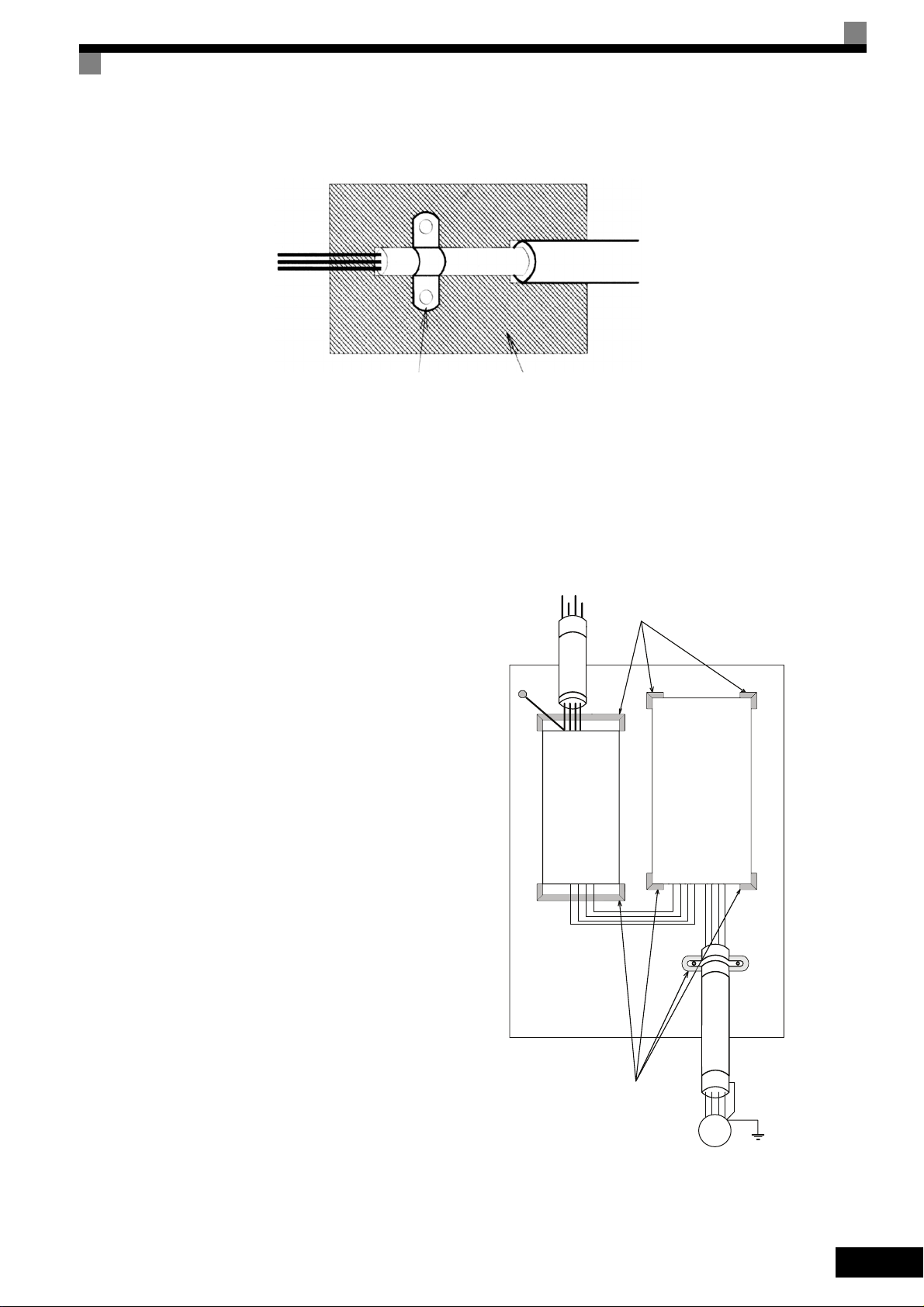
Ground clip
Ground plate
The grounding surfaces must be highly conductive bare metal. Remove any coats of varnish and paint.
–Ground the cable shields at both ends.
–Ground the motor of the machine.
Installation inverters and EMC filters
For an EMC rules compliant installation consider
the following points:
• Use a line filter.
• Use shielded motor cables.
• Mount the inverter and filter on a grounded con-
ductive plate.
• Remove any paint or dirt before mounting the
parts in order to reach the lowest possible
grounding impedance.
PEL1L2
PE
Line
Filter
Cable Lenght
as short as possible
Grounded
Metal Plate
L3
Load
Ground Bonds
Remove any paint!
Inverter
GND
L1
L2
V
GND
W
U
L3
Ground Bonds
Remove any paint!
Screened
Motor cable
M
~3
XI
Page 13

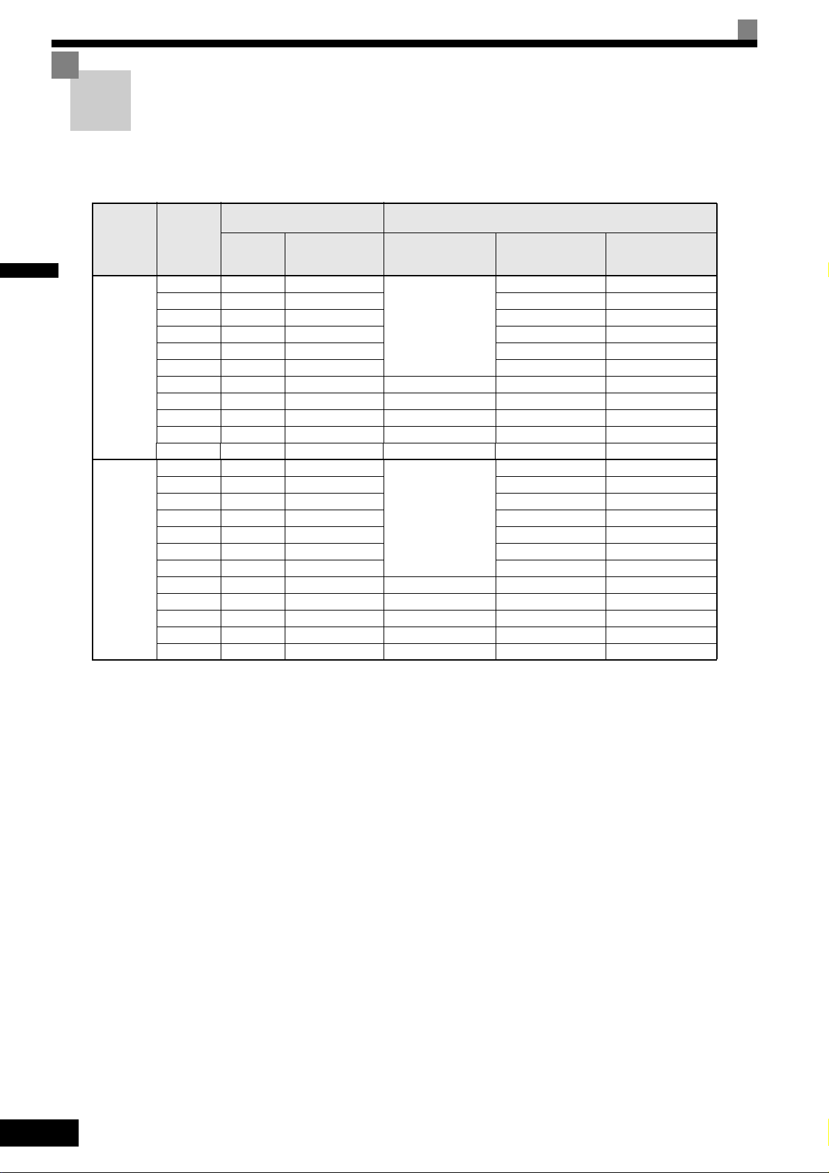
Line Filters
Recommended Line Filters for Varispeed L7
Inverter Model Line Filter
Varispeed L7 Model
CIMR-L7Z43P77
3G3RV-PFI3018-SE 18 1.3 141 x 46 x 330CIMR-L7Z44P07
CIMR-L7Z45P57
CIMR-L7Z47P57
CIMR-L7Z40117
CIMR-L7Z40157
CIMR-L7Z40187
CIMR-L7Z40227
CIMR-L7Z40307
CIMR-L7Z40377
CIMR-L7Z40557
Maximum Voltage: AC 480V 3phase
Ambient Temperature: 45°C (max.)
3G3RV-PFI3035-SE 35 2.1 206 x 50 x 355
3G3RV-PFI3060-SE 60 4.0 236 x 65 x 408
3G3RV-PFI3070-SE 70 3.4 80 x 185 x 329
3G3RV-PFI3130-SE 130 4.7 90 x 180 x 366CIMR-L7Z40457
Current
(A)
Weight
(kg)
Dimensions
W x D x H
*Permissible emission of power drive systems for commercial and light environment (EN61800-3, A11)
(general availability, 1st environment)
Inverter Model Line Filter
Varispeed L7 Model
CIMR-L7Z23P77
CIMR-L7Z25P57
CIMR-L7Z27P57 3G3RV-PFI2060-SE 60 3.0 206 x 60 x 355
CIMR-L7Z20117
CIMR-L7Z20157 3G3RV-PFI2100-SE 100 4.9 236 x 80 x 408
CIMR-L7Z20187
CIMR-L7Z20227 3G3RV-PFI2130-SE 130 4.3 90 x 180 x 366
CIMR-L7Z20307
CIMR-L7Z20377 3G3RV-PFI2160-SE 160 6.0 120 x 170 x 451
CIMR-L7Z20457 3G3RV-PFI2200-SE 200 11.0 130 x 240 x 610
CIMR-L7Z20557
Maximum Voltage: AC 240V 3phase
Ambient Temperature: 45°C (max.)
3G3RV-PFI2035-SE 35 1.4 141 x 46 x 330
Current
(A)
Weight
(kg)
Dimensions
W x D x H
XII
* max. motor cable length: 10 m Class B, 50 m Class A
Rated Voltage: AC240V 3 ph.
Ambient Temperature: 45°C (max.)
Page 14

Registered Trademarks
The following registered trademarks are used in this manual.
• DeviceNet is a registered trademark of the ODVA (Open DeviceNet Vendors Association, Inc.).
• InterBus is a registered trademark of Phoenix Contact Co.
• Profibus is a registered trademark of Siemens AG.
• Hiperface
• Klauke
y
is a registered trademark of Sick Stegmann GmbH
y
is a registered trademark of Klauke Textron
XIII
Page 15

XIV
Page 16

1
Handling Inverters
This chapter describes the checks required upon receiving or installing an Inverter.
Varispeed L7 Models ..........................................................1-2
Confirmations upon Delivery...............................................1-3
Exterior and Mounting Dimensions .....................................1-7
Checking and Controlling the Installation Site ....................1-9
Installation Orientation and Space ....................................1-10
Removing and Attaching the Terminal Cover ...................1-11
Removing/Attaching the Digital Operator/ LED Monitor and
Front Cover .......................................................................1-13
Page 17
1
Varispeed L7 Models
The Varispeed L7 Series includes Inverters in two voltage classes: 200 V and 400 V. The maximum motor capacities
vary from 3.7 to 55 kW (23 models).
Table 1.1 Varispeed L7 Models
Specifications
NEMA 1
CIMR-L7Z
20151
40371 40377
CIMR-L7Z
IEC IP20
Voltage
Class
200 V class
400 V class
Output
Capacity
kVA
Varispeed L7
Basic Model
Number
(Always specify through the protective structure when ordering.)
IEC IP00
CIMR-L7Z
Maximum
Motor
Capacity
kW
3.7 7 CIMR-L7Z23P7 23P71 23P77
5.5 10 CIMR-L7Z25P5 25P51 25P57
7.5 14 CIMR-L7Z27P5 27P51 27P57
11 20 CIMR-L7Z2011 20111 20117
15 27 CIMR-L7Z2015
18.5 33 CIMR-L7Z2018 20181 20187
22 40 CIMR-L7Z2022 20220 20221 20227
30 54 CIMR-L7Z2030 20300 20301 20307
37 67 CIMR-L7Z2037 20370 20371 20377
45 76 CIMR-L7Z2045 20450 20451 20457
55 93 CIMR-L7Z2055 20550 20551 20557
3.7 7 CIMR-L7Z43P7 43P71 43P77
4.0 9 CIMR-L7Z44P0 44P01 43P77
5.5 12 CIMR-L7Z45P5 45P51 45P57
7.5 15 CIMR-L7Z47P5 47P51 47P57
11 22 CIMR-L7Z4011 40111 40117
15 28 CIMR-L7Z4015 40151 40157
18.5 34 CIMR-L7Z4018 40181 40187
22 40 CIMR-L7Z4022 40220 40221 40227
30 54 CIMR-L7Z4030 40300 40301 40307
37 67 CIMR-L7Z4037 40370
45 80 CIMR-L7Z4045 40450 40451 40457
55 106 CIMR-L7Z4055 40550 40551 40557
20157
1-2
Page 18
Confirmations upon Delivery
Checks
Check the following items as soon as the Inverter is delivered.
Table 1.2 Checks
Item Method
Has the correct model of Inverter been
delivered?
Is the Inverter damaged in any way?
Check the model number on the nameplate on the side of the Inverter.
Inspect the entire exterior of the Inverter to see if there are any scratches or
other damage resulting from shipping.
1
Are any screws or other components
loose?
Use a screwdriver or other tools to check for tightness.
In case of any irregularities in the above items, contact the agency from which the Inverter was purchased or
your Omron-Yaskawa Motion Control representative immediately.
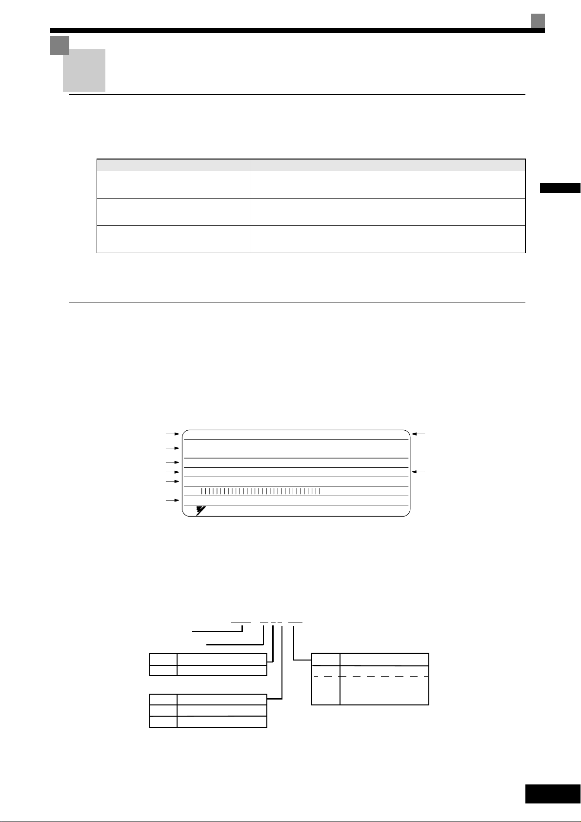
Nameplate Information
The nameplate attached to the side of each Inverter showing the model number, specifications, lot number,
serial number and other information about the Inverter.
Example Nameplate
The following nameplate is an example for a standard European Inverter: 3-phase, 400 VAC,
3.7 kW, IEC IP20 standards
Inverter model
Input specification
Output specification
Lot number
Serial number
UL file number
MODEL
INPUT
OUTPUT
O/N
S/N
FILE NO E131457
CIMR-L7Z43P7
AC3PH 380-480V 50/60Hz 10.2A
AC3PH 0-480V 0-120Hz 8.5A 3min. 50%ED 8.5kVA
YASKAWA ELECTRIC CORPORARION
SPEC: 43P77A
MASS: 4.0 kg
PRG:
MADE IN JAPA N
M
Inverterspecifications
Mass
s
Fig 1.1 Nameplate
Inverter Model Numbers
The model number of the Inverter on the nameplate indicates the specification, voltage class, and maximum
motor capacity of the Inverter in alphanumeric codes.
CIMR – L7 Z 2 3P7
Inverter
Varispeed L7
No.
Z
No.
2
4
Specification
OYMC European Std.
Voltage Class
AC Input, 3-phase, 200 V
AC Input, 3-phase, 400 V
3P7
5P5
55
“P” Indicates the decimal point.
Fig 1.2 Inverter Model Numbers
Max. Motor Capacity
No.
to
3.7 kW
5.5 kW
to
55 kW
1-3
Page 19

1
Inverter Specifications
The Inverter specifications (“SPEC”) on the nameplate indicate the voltage class, maximum motor capacity,
the protective structure, and the revision of the Inverter in alphanumeric codes.
2
3P7 1 B
No.
2
4
Voltage Class
AC Input, 3-phase, 200 V
AC Input, 3-phase 400 V
No.
Hardware Revision
A
Spec A
Spec B
B
Max. Motor Capacity
No.
3P7
5P5
to
55
“P” Indicates the decimal point
3.7 kW
5.5 kW
to
55 kW
No.
0
1
7
Protective Structure
IP00
NEMA 1
IP20
Fig 1.3 Inverter Specifications
Inverter Software Version
The inverter software version can be read out from the monitor parameter U1-14. The parameter shows the
last for digits of the software number (e.g. display is “2031” for the software version VSL702031).
This manual describes the functionality of the inverter software version VSL702031
Older software versions may not support all described functions. Check the software version
IMPORTANT
before start working with this manual!
1-4
Page 20
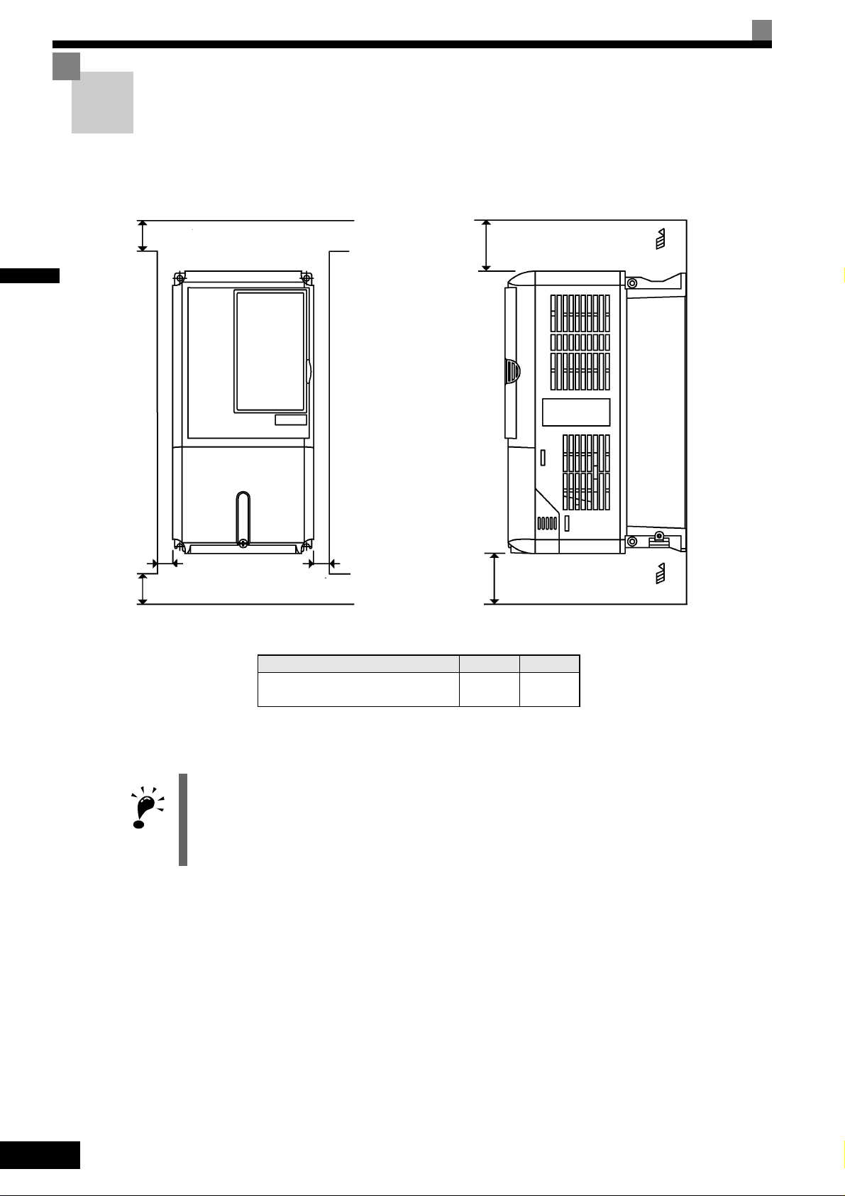
Component Names
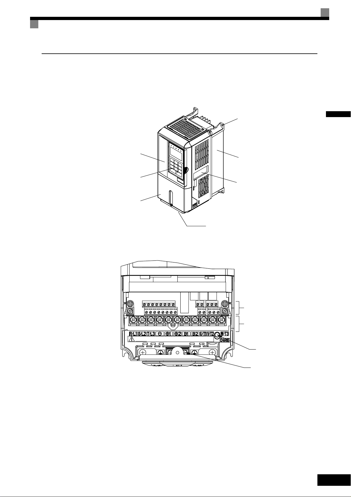
Inverters of 18.5 kW or Less
The external appearance and component names of the Inverter are shown in Fig 1.4. The Inverter with the terminal cover removed is shown in Fig 1.5.
Mounting holes
1
Front cover
Digital Operator
Terminal cover
Fig 1.4 Inverter Appearance (18.5 kW or Less)
Heatsink
Nameplate
Bottom Protective Cover
Control circuit terminals
Main circuit terminals
Fig 1.5 Terminal Arrangement (18.5 kW or Less)
Charge indicator
Ground terminal
1-5
Page 21
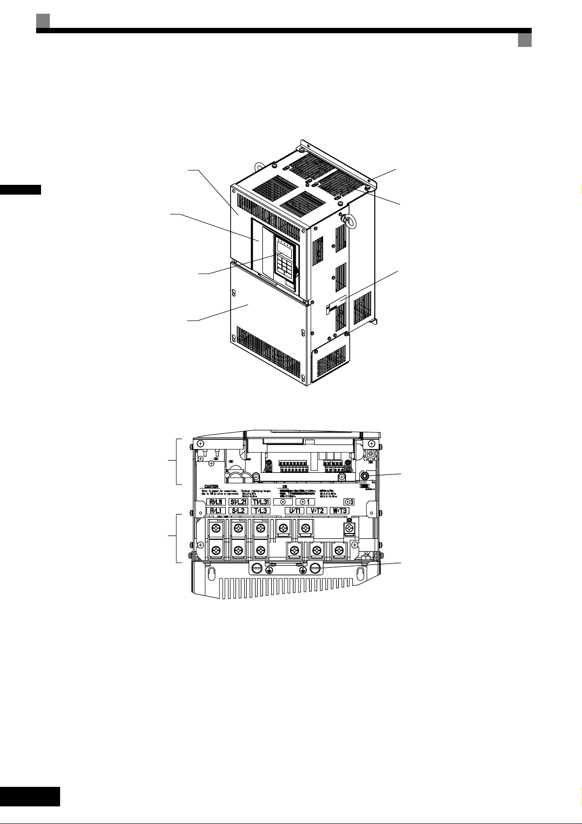
Inverters of 22 kW or More
The external appearance and component names of the Inverter are shown in Fig 1.6. The Inverter with the terminal cover removed is shown in Fig 1.7.
1
Inveter cover
Front cover
Digital Operator
Terminal cover
Mounting holes
Cooling fan
Nameplate
Fig 1.6 Inverter Appearance (22 kW or More)
Control circuit
terminals
Main circuit
terminals
Charge indicator
Ground terminals
Fig 1.7 Terminal Arrangement (22 kW or More)
1-6
Page 22
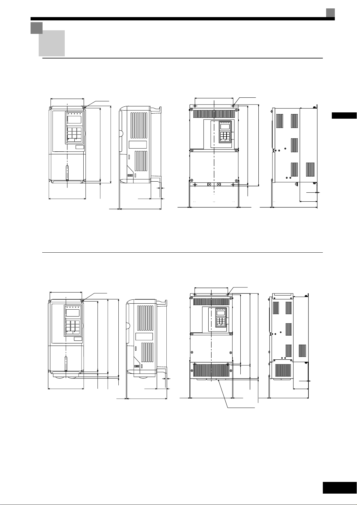
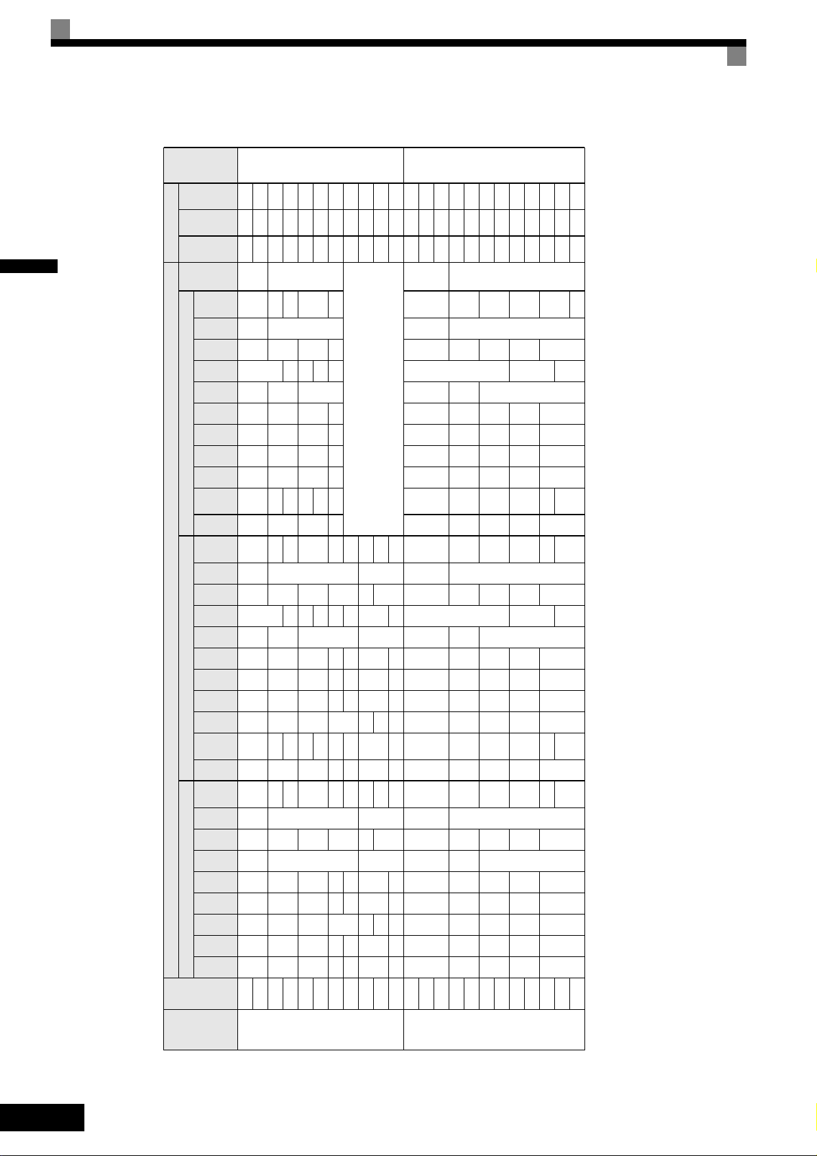
Exterior and Mounting Dimensions
IP00 Inverters
Exterior diagrams of the IP00 Inverters are shown below.
W1
W
200 V/400 V Class Inverters of 3.7 to 18.5 kW
4-d
H1H2DH
3
Fig 1.8 Exterior Diagrams of IP00 Inverters
IP20 / NEMA 1 Inverters
D1
W1
4-d
1
H
H1
t1
H2
max. 10
W
200 V Class Inverters of 22 or 55 kW
400 V Class Inverters of 22 to 55 kW
max. 10
max. 5
t1
D1
D
Exterior diagrams of the IP20/NEMA1 Inverters are shown below.
W1
W
200 V/400 V Class Inverters of 3.7 to 18.5 kW
4-d
H1H2DH0
H3
t1
4 H
3
D1
max. 10
200 V Class Inverters of 22 or 55 kW
400 V Class Inverters of 22 to 55 kW
Fig 1.9 Exterior Diagrams of IP20/NEMA1 Inverters
W1
W
4-d
H1
H2
Grommet
H0
H3
H
Max.10
t1
D1
max. 5max. 10
D
1-7
Page 23
1
ing
Cool-
Method
era-
tion
Heat
Gen-
Tot al
nal
Inter-
nal
112 7 4 186
Exter
d*
ing
Holes
Mount
rox.
App-
Mass
W H D W1 H0 H1 H2 H3 D1 t1
rox.
App-
Mass
Dimensions (mm) Caloric Value (W)
219 113 332
6
59 5 4 M5
0
300
6
59 5 4 140 280 177 126 280 266 7
0
197 186 300 285 8 65.5
200
429 183 612
M6
2.3
0
350
0
78 11
207 216 350 335
2.3
78 11 240
Fan
7.5
7.5
Fan
80 68 148
20 254 464 258 195 400 385 64 100 19 586 274 860
57 1015 411 1426
62 1266 505 1771
3.2
100
100
130
209
12.5
193 114 307
326 172 498
466 259 725
784 360 1144
901 415 1316
M6
6
59 5 4 M5
59 5 4 140 280 177 126 280 266 7
78 10
0
6 200 300 197 186 300 285 8 65.5
78 10 240 350 207 216 350 335
0
34
2.3
100 19
64
7.5
283 260 550 535 105
614
329
35
2.3
100 20 279 514.5 258 220 450 435
85
7.5
Max.
Appli-
IP00 NEMA1 IP20
195 400 385 135
250 600 575
197 186 300 285 8 65.5
App-
W H D W1 H0 H1 H2 H3 D1 t1
rox
207 216 350 335
258
298
300
350
200
Mass
6
2.3
65.5
7.5
17 254 535
380 809
52
57 328
3.2
100
100
130
12.5
6 200 300 197 186 300 285 8 65.5
2.3
78 10 240 350 207 216 350 335
283 260 550 535 105
635
329
31
30 715 165 34 629.5 79.5
7.5
Table 1.3 Inverter Dimensions (mm) and Masses (kg)
195 385
250 575
258
298
W H D W1 H1 H2 D1 t1
140 280 177 126 266 7 59 5 4 140 280 177 126 280 266 7
200 300 197 186 285
240 350 207 216 335 78 11 240
11 7 310 10 7 310 10 7 374 170 544
7.5
15
18.5 380 30 380 30 501 211 712
200 V
(3-phase)
3.7
[kW]
5.5 164 84 248
cable
Motor
Output
Class
Voltage
22 250 400
375 600
30 275 450 220 435 20 279 615 220 450 435 165 23 865 352 1217
37
45 328
140 280 177 126 266 7 59 5 4 140 280 177 126 280 266 7
55 450 725 348 325 700 78 453 1027 350 325 725 700 302 86 1588 619 2207
3.7
4.0 91 70 161
5.5 127 82 209
7.5
200 300 197 186 285 8 65.5
240 350 207 216 335
275 450 258 220 435 100 17 279 535 258 220 450 435
325 550 283 260 535 105
11 252 158 410
15
22
30 678 317 995
37
45
55 33 1203 495 1698
400 V
18.5 426 208 634
(3-phase)
1-8
Page 24

Checking and Controlling the Installation Site
Install the Inverter in the installation site described below and maintain optimum conditions.
Installation Site
Install the Inverter under the following conditions in a pollution degree 2 environment.
Table 1.4 Installation Site
Type Ambient Operating Temperature Humidity
NEMA1 / IP20 -10 to + 40 °C 95% RH or less (no condensation)
IEC IP00 -10 to + 45 °C 95% RH or less (no condensation)
Protection covers are attached to the top and bottom of the Inverter. Be sure to remove the protection covers
before installing a 200 or 400 V Class Inverter with an output of 18.5 kW or less in a panel.
Observe the following precautions when mounting the Inverter.
• Install the Inverter in a clean location which is free from oil mist and dust. It can be installed in a totally
enclosed panel that is completely shielded from floating dust.
• When installing or operating the Inverter, always take special care so that metal powder, oil, water, or other
foreign matter does not get into the Inverter.
• Do not install the Inverter on combustible material, such as wood.
• Install the Inverter in a location free from radioactive materials and combustible materials.
• Install the Inverter in a location free from harmful gasses and liquids.
• Install the Inverter in a location without excessive oscillation.
• Install the Inverter in a location free from chlorides.
• Install the Inverter in a location not in direct sunlight.
1
Controlling the Ambient Temperature
To enhance the reliability of operation, the Inverter should be installed in an environment free from extreme
temperature increases. If the Inverter is installed in an enclosed environment, such as a cabinet, use a cooling
fan or air conditioner to maintain the internal air temperature below 45°C.
Protecting the Inverter from Foreign Matter
Place a cover over the Inverter during installation to shield it from metal power produced by drilling.
Always remove the cover from the Inverter after the completion of the installation. Otherwise, ventilation will
be reduced, causing the Inverter to overheat.
1-9
Page 25
Installation Orientation and Space
T
Install the Inverter vertically so as not to reduce the cooling effect. When installing the Inverter, always provide the following installation space to allow normal heat dissipation.
1
A
30 mm min.
50 mm min.
Horizontal Space
30 mm min.
B
Air
120 mm min.
Air
Vertical Space
IMPORTAN
A B
200V class inverter, 3.7 to 55 kW
400V class inverter, 3.7 to 55 kW
Fig 1.10 Inverter Installation Orientation and Space
1. The same space is required horizontally and vertically for IP00, IP20 and NEMA 1 Inverters.
2. Always remove the top protection cover after installing an Inverter with an output of 18.5 kW or less in a
panel.
Always provide enough space for suspension eye bolts and the main circuit lines when installing an
Inverter with an output of 22 kW or more in a panel.
50 mm 120 mm
1-10
Page 26
Removing and Attaching the Terminal Cover
Remove the terminal cover to wire cables to the control circuit and main circuit terminals.
Before opening the terminal cover, switch off the power supply and wait at least 5 min. to make sure, that
the DC bus is discharged!
IMPORTANT
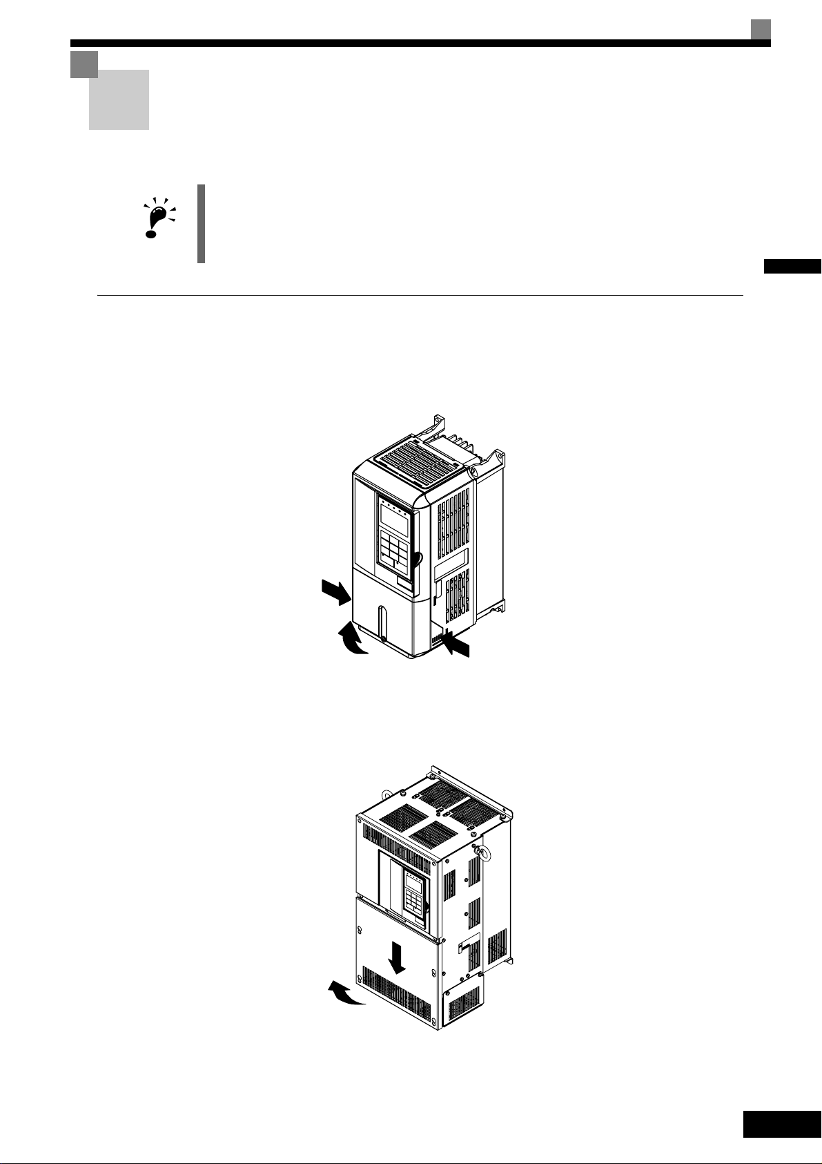
Removing the Terminal Cover
Inverters of 18.5 kW or Less
Loosen the screw at the bottom of the terminal cover, press in on the sides of the terminal cover in the directions of arrows 1, and then lift up on the terminal in the direction of arrow 2.
1
1
2
Fig 1.11 Removing the Terminal Cover (Model CIMR-L7Z43P7 Shown Above)
Inverters of 22 kW or More
Loosen the screws on the left and right at the top of the terminal cover, pull out the terminal cover in the direction of arrow 1 and then lift up on the terminal in the direction of arrow 2.
2
1
1
Fig 1.12 Removing the Terminal Cover (Model CIMR-L7Z4022 Shown Above)
1-11
Page 27

1
Attaching the Terminal Cover
When the terminal block wiring has been completed, attach the terminal cover by reversing the removal procedure.
For Inverters with an output of 18.5 kW or less, insert the tab on the top of the terminal cover into the groove
on the Inverter and press in on the bottom of the terminal cover until it clicks into place.
1-12
Page 28
Removing/Attaching the Digital Operator/ LED Monitor and Front Cover
Inverters of 18.5 kW or Less
To attach optional cards or change the terminal card connector, remove the Digital Operator/LED Monitor and
front cover in addition to the terminal cover. Always remove the Digital Operator/LED Monitor from the front
cover before removing the front cover.
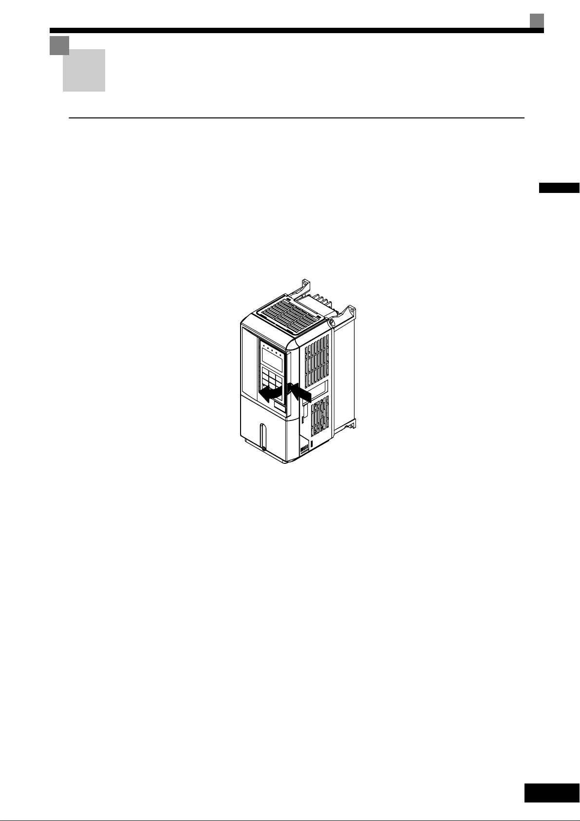
The removal and attachment procedures are described below.
Removing the Digital Operator/LED Monitor
Press the lever on the side of the Digital Operator/LED Monitor in the direction of arrow 1 to unlock the Digital Operator/LED Monitor and lift the Digital Operator/LED Monitor in the direction of arrow 2 to remove
the Digital Operator/LED Monitor as shown in the following illustration.
1
2
Fig 1.13 Removing the Digital Operator/LED Monitor (Model CIMR-L7Z43P7 Shown Above)
1
1-13
Page 29
1
Removing the Front Cover
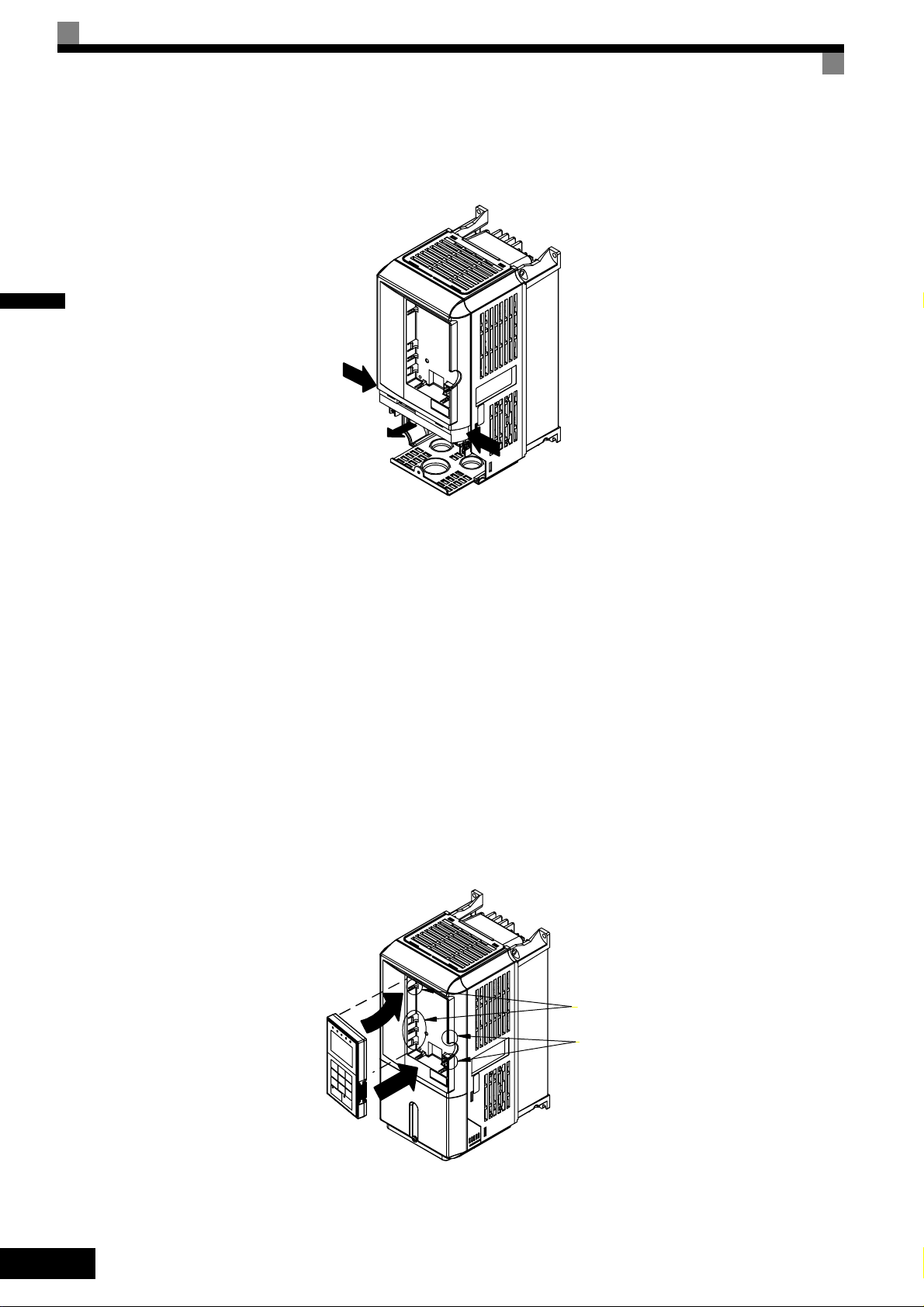
Press the left and right sides of the front cover in the directions of arrows 1 and lift the bottom of the cover in
the direction of arrow 2 to remove the front cover as shown in the following illustration.
1
2
1
Fig 1.14 Removing the Front Cover (Model CIMR-L7Z43P7 Shown Above)
Mounting the Front Cover
After wiring the terminals, mount the front cover to the Inverter by performing the steps to remove the front
cover in reverse order.
1. Do not mount the front cover with the Digital Operator/LED Monitor attached to the front cover; otherwise, Digital Operator/LED Monitor may malfunction due to imperfect contact.
2. Insert the tab of the upper part of the front cover into the groove of the Inverter and press the lower part of
the front cover onto the Inverter until the front cover snaps shut.
Mounting the Digital Operator/LED Monitor
After attaching the terminal cover, mount the Digital Operator/LED Monitor onto the Inverter using the following procedure.
1. Hook the Digital Operator/LED Monitor at A (two locations) on the front cover in the direction of arrow 1
as shown in the following illustration.
2. Press the Digital Operator/LED Monitor in the direction of arrow 2 until it snaps in place at B (two locations).
A
B
Fig 1.15 Mounting the Digital Operator/LED Monitor
1-14
Page 30
1. Do not remove or attach the Digital Operator/LED Monitor or mount or remove the front cover using methods other than those described above, otherwise the Inverter may break or malfunction due to imperfect
contact.
IMPORTANT
2. Never attach the front cover to the Inverter with the Digital Operator/LED Monitor attached to the front
cover. Imperfect contact can result.
Always attach the front cover to the Inverter by itself first, and then attach the Digital Operator/LED Monitor to the front cover.
Inverters of 22 kW or More
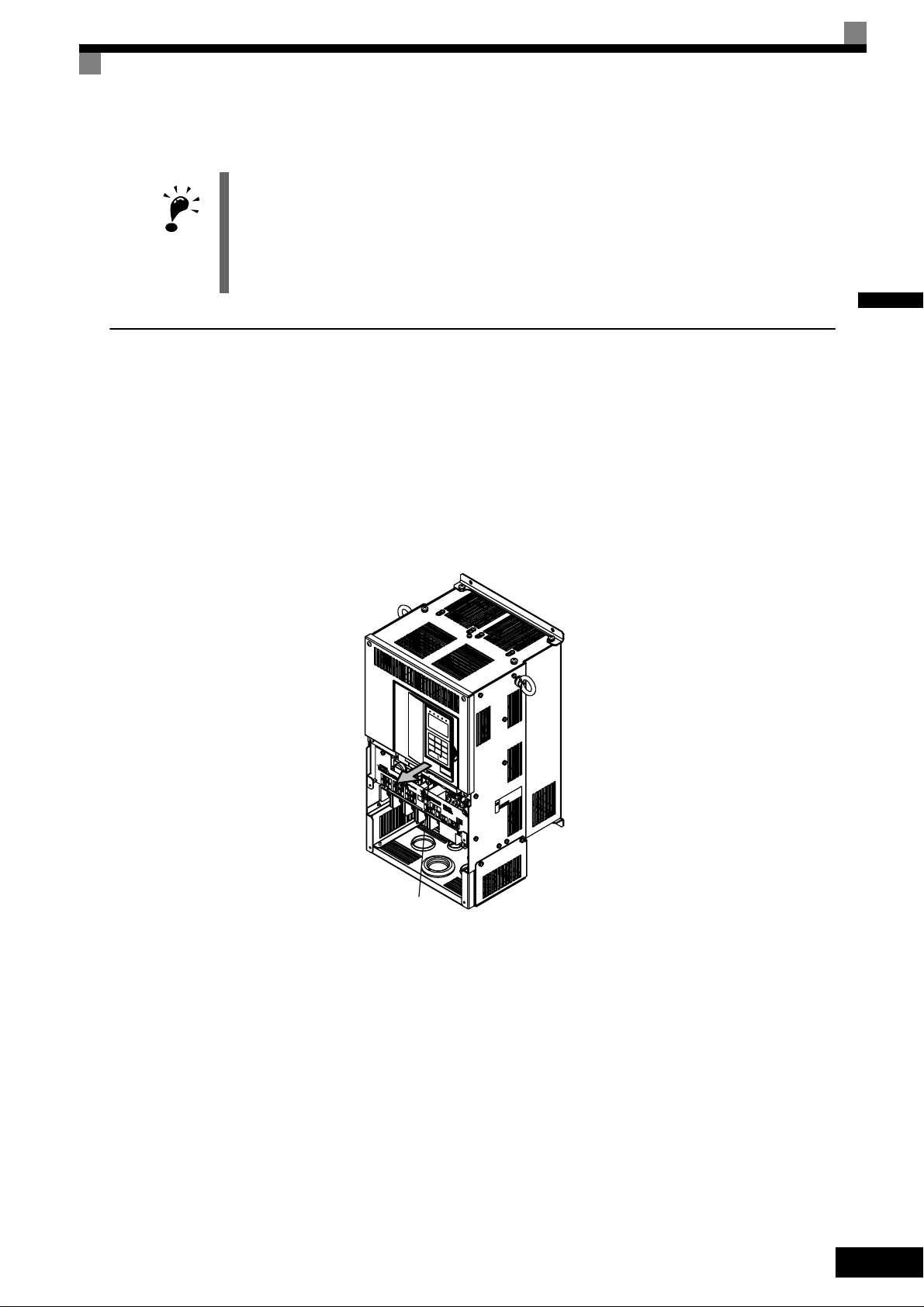
For inverters with an output of 22 kW or more, remove the terminal cover and then use the following procedures to remove the Digital Operator/LED Monitor and front cover.
Removing the Digital Operator/LED Monitor
Use the same procedure as for Inverters with an output of 18.5 kW or less.
Removing the Front Cover
Lift up at the location label 1 at the top of the control circuit terminal card in the direction of arrow 2.
1
2
1
Fig 1.16 Removing the Front Cover (Model CIMR-L7Z4022 Shown Above)
Attaching the Front Cover
After completing the required work, such as mounting an optional card or setting the terminal card, attach the
front cover by reversing the procedure to remove it.
1. Confirm that the Digital Operator/LED Monitor is not mounted on the front cover. Contact faults can occur
if the cover is attached while the Digital Operator/LED Monitor is mounted to it.
2. Insert the tab on the top of the front cover into the slot on the Inverter and press in on the cover until it
clicks into place on the Inverter.
Attaching the Digital Operator/LED Monitor
Use the same procedure as for Inverters with an output of 18.5 kW or less.
1-15
Page 31

1
1-16
Page 32

2
Wiring
This chapter describes the terminals, main circuit terminal connections, main circuit terminal wiring specifications, control circuit terminals, and control circuit wiring specifications.
Connection Diagram ...........................................................2-2
Terminal Block Configuration..............................................2-4
Wiring Main Circuit Terminals .............................................2-5
Wiring Control Circuit Terminals .......................................2-17
EN81-1 Conform Wiring with One Motor Contactor..........2-21
Wiring Check.....................................................................2-23
Installing and Wiring Option Cards ...................................2-24
Page 33

Connection Diagram
The connection diagram of the Inverter is shown in Fig 2.1.
When using the Digital Operator, the motor can be operated by wiring only the main circuits.
2
3-phase power
380 to 480V
50/60Hz
Multi function
Inputs
(Factory setting)
Magnetic
Contactor
L1
L2
L3
PE
Forward run/stop
Reverse run/stop
Nominal Speed
Inspection Run
Intermediate Speed
Leveling Speed
Not used
Hardware Baseblock (note 3)
Analog input
(Speed reference)
Voltage adjustment
2kOhm
Input option cards
2kOhm
0 to 10 V
Line
Filter
P
DC reactor to improve input
power factor (optional)
Link
(+1) (+2)
L1(R)
L2(S)
L3(T)
S1
S2
S3
S4
S5
S6
S7
BB
BB1
SC
CN5(NPN setting)
E(G)
+V
Analog input power
supply +15V, 20mA
A1
Master speed
reference 0 to 10V
AC
0 V
2CN
(-)
+24V, 8mA
IP24V (24V)
Braking Resistor
unit (optional)
B1
U/T1
V/T2
W/T3
PG-X2
(Optional)
B2
TA1
TA3
TA2
MA
MB
MC
M1
M2
M3
M4
M5
M6
1
A Pulse
B Pulse
Z Pulse
Brake Command
(Factory setting)
Contactor Control
(Factory setting)
Inverter Ready
(Factory setting)
Pulse Monitor Output
RS-422
(100m or less)
2
3
Fault contact output
250VAC, max. 1A
30VDC, max. 1A
P
P
Motor
IM/PM
PG
Multi-function
contact output
250VAC, max. 1A
30VDC, max. 1A
2-2
Optional control power
supply input for Rescue
Operation
Note:
. Main circuit terminals are indicatied with double circles and
1
control circuit terminals are indicatied with a single circles
2. The CN5 factory setting is NPN
3. To enable the inverter both inputs, BB and BB1 must be closed. If
only one of the inputs is closed, “BB” will be displayed in the
operator panel and the inverter will not start.
to terminal B1
to terminal -
Fig 2.1 Connection Diagram (Model CIMR-L7Z43P7 Shown Above)
P0
Control Power
Supply Input
N0
1
Shielded
wires
3CN
Twisted-pair
wires
Output option
cards
2
Page 34

Circuit Descriptions
Refer to the numbers indicated in Fig 2.1.
1 These circuits are hazardous and are separated from accessible surfaces by protective separation
2 These circuits are separated from all other circuits by protective separation consisting of double and
reinforced insulation. These circuits may be interconnected with SELV
*
circuits, but not both.
SELV
3 Inverters supplied by a four-wire-system source (neutral grounded)
These circuits are SELV
consisting of double and reinforced insulation. These circuits may only be interconnected with
other SELV
Inverters supplied by a three-wire-system source (ungrounded or corner grounded)
These circuits are not separated from hazardous circuits other circuits by protective separation, but
only with basic insulation. These circuits must not be interconnected with any circuits which are
accessible, unless they are isolated from accessible circuits by supplemental insulation
* SELV (Safety Extra Low Voltage) circuits have no direct connection to the primary power and are supplied by a transformer or equivalent isolating
device. The circuits are designed and protected, so that, under normal and single fault condition, its voltage does not exceed a safe value.
(See IEC 61010)
1. Control circuit terminals are arranged as shown below.
*
(or equivalent) circuits.
*
(or equivalent) or non-
*
circuits and are separated from all other circuits by protective separation
2
IMPORTANT
SC SC SC
E(G)
2. The output current capability of the +V terminal is 20 mA.
3. Main circuit terminals are indicated with double circles and control circuit terminals are indicated with single circles.
4. The wiring of the digital inputs S1 to S7 and BB is shown for the connection of contacts or NPN transistors (0V common and sinking mode). This is the default setting.
For the connection of PNP transistors or for using a 24V external power supply, refer to
5. A DC reactor is an option only for Inverters of 18.5 kW or less. Remove the short circuit bar when connecting a DC reactor.
S1
S2
BB
S3 S4
+V
A1 AC
S5 S6 S7 BB1
M5
M6
M3
MA MB MC
M4
M1
M2
E(G)
Table 2.10.
2-3
Page 35

Terminal Block Configuration
The terminal arrangements are shown in Fig 2.2 and Fig 2.3.
Control circuit terminals
2
Control
circuit
terminals
Main
circuit
terminals
Main circuit terminals
Charge indicator
Ground terminal
Fig 2.2 Terminal Arrangement (200 V/400 V Class Inverter of 3.7 kW)
Charge indicator
Ground terminals
2-4
Fig 2.3 Terminal Arrangement (200 V/400 V Class Inverter of 22 kW or more)
Page 36

Wiring Main Circuit Terminals
Applicable Wire Sizes and Crimp Terminals
Select the appropriate wires and crimp terminals using Table 2.1 to Table 2.3. Refer to instruction manual
TOE-C726-2 for wire sizes for Braking Resistor Units and Braking Units.
Wire Sizes
Table 2.1 200 V Class Wire Sizes
Inverter
Model
CIMR-
L7Z23P7
Terminal Symbol
R/L1, S/L2, T/L3, , 1, 2, B1, B2,
U/T1, V/T2, W/T3, PO, NO
Terminal
Screws
Tightening
Torque
(N•m)
M4 1.2 to 1.5
Possible
Wire Sizes
2
(AWG)
mm
4
(12 to 10)
Recom-
mended
Wire Size
2
mm
(AWG)
4
(12)
*1
Wire Type
2
L7Z25P5
L7Z27P5
L7Z2011
L7Z2015
L7Z2018
L7Z2022
L7Z2030
R/L1, S/L2, T/L3, , 1, 2, B1, B2,
U/T1, V/T2, W/T3, PO, NO
R/L1, S/L2, T/L3, , 1, 2, B1, B2,
U/T1, V/T2, W/T3, PO, NO
R/L1, S/L2, T/L3, , 1, 2, B1, B2,
U/T1, V/T2, W/T3, PO, NO
R/L1, S/L2, T/L3, , 1, 2, U/T1, V/T2,
W/T3, NO
B1, B2, PO M5 2.5
R/L1, S/L2, T/L3, , 1, 2, U/T1, V/T2,
W/T3, NO
B1, B2, PO M5 2.5
R/L1, S/L2, T/L3, , 1, U/T1, V/T2,
W/T3, R1/L11, S1/L21, T1/L31, NO
3, PO
R/L1, S/L2, T/L3, , 1 U/T1,
V/T2, W/T3, R1/L11, S1/L21, T1/L31, NO
3, PO
M4 1.2 to 1.5
M5 2.5
M5 2.5
M6 4.0 to 5.0
M6 4.0 to 5.0
M8 9.0 to 10.0
M6 4.0 to 5.0
M8 9.0 to 10.0
M6 4.0 to 5.0
M8 9.0 to 10.0
M8 9.0 to 10.0
M6 4.0 to 5.0
M8 9.0 to 10.0
6
(10)
10
(8 to 6)
16
(6 to 4)
25
(4 to 2)
10
(8 to 6)
25
(4)
25 to 35
(3 to 2)
10 to 16
(8 to 6)
25
(4)
25 to 35
(3 to 1)
10 to 16
(8 to 4)
25 to 35
(4 to 2)
50
(1 to 1/0)
10 to 16
(8 to 4)
25 to 35
(4 to 2)
6
(10)
10
(8)
16
(6)
25
(4)
-
25
(4)
25
(3)
-
25
(4)
25
(3)
-
25
(4)
50
(1)
-
25
(4)
Power cables,
e.g., 600 V vinyl
power cables
2-5
Page 37

2
Inverter
Model
CIMR-
L7Z2037
Terminal Symbol
R/L1, S/L2, T/L3, , 1 U/T1,
V/T2, W/T3, R1/L11, S1/L21, T1/L31, NO
3, PO
Terminal
Screws
M10 17.6 to 22.5
M8 8.8 to 10.8
M10 17.6 to 22.5
r/l1, Δ/l2 M4 1.3 to 1.4
L7Z2045
R/L1, S/L2, T/L3, , 1 U/T1,
V/T2, W/T3, R1/L11, S1/L21, T1/L31, NO
3, PO
M10 17.6 to 22.5
M8 8.8 to 10.8
M10 17.6 to 22.5
r/l1,
Δ/l2 M4 1.3 to 1.4
R/L1, S/L2, T/L3, , 1, NO
M12 31.4 to 39.2
U/T1, V/T2, W/T3, R1/L11, S1/L21, T1/L31 M10 17.6 to 22.5
L7Z2055
3, PO
M8 8.8 to 10.8
M10 17.6 to 22.5
r/l1,
Δ/l2 M4 1.3 to 1.4
*1. The wire size is valid for PVC insulated copper cable, 30° ambient temperature
Tightening
Torque
(N•m)
Possible
Wire Sizes
2
mm
(AWG)
Recommended
Wire Size
mm
70 to 95
(2/0 to 4/0)70(2/0)
6 to 16
(10 to 4)
35 to 70
(2 to 2/0)
0.5 to 4
(20 to 10)
95
(3/0 to 4/0)95(3/0)
6 to 16
(10 to 4)
50 to 70
(1 to 2/0)
0.5 to 4
(20 to 10)
50 to 95
(1/0 to 4/0)
50 × 2P
(1/0 × 2P)
90
(4/0)
(4/0)
6 to 70
(10 to 2/0)
35 to 95
(3 to 4/0)
(1/0)
0.5 to 4
(20 to 10)
2
(AWG)
–
35
(2)
1.5
(16)
–
50
(1)
1.5
(16)
90
–
50
1.5
(16)
Wire Type
*1
Power cables,
e.g., 600 V vinyl
power cables
Inverter
Model
CIMR-
L7Z43P7
L7Z44P0
L7Z45P5
L7Z47P5
L7Z4011
Terminal Symbol
R/L1, S/L2, T/L3, , 1, 2, B1, B2,
U/T1, V/T2, W/T3, NO, PO
R/L1, S/L2, T/L3, , 1, 2, B1, B2,
U/T1, V/T2, W/T3, NO, PO
R/L1, S/L2, T/L3, , 1, 2, B1, B2,
U/T1, V/T2, W/T3, NO, PO
R/L1, S/L2, T/L3, , 1, 2, B1, B2,
U/T1, V/T2, W/T3, NO, PO
R/L1, S/L2, T/L3, , 1, 2, B1, B2,
U/T1, V/T2, W/T3, NO, PO
Table 2.2 400 V Class Wire Sizes
Terminal
Screws
Tightening
Torque
(N•m)
M4 1.2 to 1.5
M4 1.2 to 1.5
M4 1.2 to 1.5
M4 1.2 to 1.5
M5 2.5
Possible
Wire Sizes
2
mm
(AWG)
2.5 to 4
(14 to 10)
2.5 to 4
(14 to 10)
4
(12 to 10)
2.5 to 4
(14 to 10)
6 to 10
(10 to 6)
6 to 10
(10 to 6)
Recom-
mended
Wire Size
2
mm
(AWG)
4
(12)
2.5
(14)
4
(12)
2.5
(14)
4
(12)
2.5
(14)
6
(10)
4
(12)
10
(8)
6
(10)
Wire Type
*1
Power cables,
e.g., 600 V vinyl
power cables
2-6
Page 38

Inverter
Model
CIMR-
R/L1, S/L2, T/L3, , 1, 2, B1, B2,
L7Z4015
L7Z4018
L7Z4022
L7Z4030
L7Z4037
L7Z4045
L7Z4055
*1. The wire size is valid for PVC insulated copper cable, 30° ambient temperature
U/T1, V/T2, W/T3, NO, PO
R/L1, S/L2, T/L3, , 1, 2, U/T1, V/T2,
W/T3, NO
B1, B2, PO M5 2.5
R/L1, S/L2, T/L3, , 1, 3, U/T1, V/T2,
W/T3, R1/L11, S1/L21, T1/L31, NO, PO
R/L1, S/L2, T/L3, , 1, 3, U/T1, V/T2,
W/T3, R1/L11, S1/L21, T1/L31, NO, PO
R/L1, S/L2, T/L3, , 1, U/T1, V/T2, W/T3,
R1/L11, S1/L21, T1/L31, NO
3, PO
R/L1, S/L2, T/L3, , 1, U/T1, V/T2, W/T3,
R1/L11, S1/L21, T1/L31, NO
3, PO
R/L1, S/L2, T/L3, , 1, U/T1, V/T2,
W/T3, R1/L11, S1/L21, T1/L31, NO
3, PO
Terminal Symbol
Terminal
Screws
M5 2.5
M5
(M6)
M6 4.0 to 5.0
M6 4.0 to 5.0
M6 4.0 to 5.0
M8 9.0 to 10.0
M6 4.0 to 5.0
M8 9.0 to 10.0
M8 9.0 to 10.0
M6 4.0 to 5.0
M8 9.0 to 10.0
M8 9.0 to 10.0
M6 4.0 to 5.0
M8 9.0 to 10.0
M8 9.0 to 10.0
M6 4.0 to 5.0
M8 9.0 to 10.0
Tightening
Torque
(N•m)
2.5
(4.0 to 5.0)
Possible
Wire Sizes
2
mm
(AWG)
10
(8 to 6)
6 to 10
(10 to 6)
10 to 35
(8 to 2)
10
(8)
10 to 25
(8 to 4)
16
(6 to 4)
16 to 35
(6 to 2)
25
(4)
25 to 35
(4 to 2)
25 to 50
(4 to 1/0)
10 to 16
(8 to 4)
25 to 35
(4 to 2)
35 to 50
(2 to 1/0)
10 to 16
(8 to 4)
25 to 35
(4 to 2)
50
(1 to 1/0)
10 to 16
(8 to 4)
25 to 35
(4 to 2)
Recommended
Wire Size
2
mm
(AWG)
10
(8)
6
(10)
10
(8)
10
(8)
10
(8)
16
(6)
16
(6)
25
(4)
25
(4)
35
(2)
-
25
(4)
35
(2)
-
25
(4)
50
(1)
-
25
(4)
Wire Type
*1
Power cables,
e.g., 600 V vinyl
power cables
2
2-7
Page 39

2
Recommended Crimp Terminal Sizes (Ring type)
Table 2.3 Crimp Terminal Sizes
Wire Cross Section (mm2)
0.5 - 1.0 M4 620/4 1620/4 GS4-1
1.5 M4 630/4 1620/4 GS4-1
2.5 M4 630/4 1630/4 GS4-2.5
4 M4 650/4 1650/4 GS4-6
6
10
16
25
35
50
70
95
*1. Not applicable for L7Z2011
Terminal Screws
A B
M4 650/4 1650/4 GS4-6
M5 101 R/5 1650/5 GS5-6
M6 101 R/6 1650/6 GS6-6
M8 101 R/8 1650/8 GS6-8
M5 102 R/5 1652/5 GS5-10
M6 102 R/6 1652/6 GS6-10
M8 102 R/8 1652/8 GS8-10
M5
M6 103 R/6 1653/6 GS6-16
M8 103 R/8 1653/8 GS8-16
M6 104 R/6 1654/6 GS6-25
M8 104 R/8 1654/8 GS8-25
M6 105 R/6 1655/6 GS6-35
M8 105 R/8 1655/8 GS8-35
M10 105 R/10 1655/10 GS10-35
M8 106 R/8 1656/8 GS8-50
M10 106 R/10 1656/10 GS10-50
M12 106 R/12 1656/12 GS12-50
M8 107 R/8 1657/8 GS8-70
M10 107 R/10 1657/10 GS10-70
M12 107 R/12 1657/12 GS12-70
M10 108 R/10 1658/10 GS10-95
M12 108 R/12 1658/12 GS12-95
103 R/5
*1
Crimp Terminal Type
y
Klauke
1653/5 GS5-16
JST
2-8
IMPORTANT
Select the wire size for the main circuit so that line voltage drop is within 2% of the rated voltage.
Line voltage drop is calculated as follows:
Line voltage drop (V) =
x wire resistance (Ω/km) x wire length (m) x current (A) x 10
3
-3
Page 40

Main Circuit Terminal Functions
Main circuit terminal functions are summarized according to terminal symbols in Table 2.4. Wire the terminals
correctly for the desired purposes.
Table 2.4 Main Circuit Terminal Functions (200 V Class and 400 V Class)
Purpose Terminal Symbol
Main circuit power input
Inverter outputs U/T1, V/T2, W/T3 23P7 to 2055 43P7 to 4055
DC bus terminals
Braking Resistor Unit connection B1, B2 23P7 to 2018 43P7 to 4018
DC reactor connection
Braking Unit connection
Ground 23P7 to 2055 43P7 to 4055
Control Power Supply PO, NO 23P7 to 2055 43P7 to 4055
R/L1, S/L2, T/L3 23P7 to 2055 43P7 to 4055
R1/L11, S1/L21, T1/L31 2022 to 2055 4022 to 4055
1,
1, 2
3,
Model: CIMR-L7Z
200 V Class 400 V Class
23P7 to 2055 43P7 to 4055
23P7 to 2018 43P7 to 4018
2022 to 2055 4022 to 4055
2
2-9
Page 41

2
Main Circuit Configurations
The main circuit configurations of the Inverter are shown in Table 2.5.
Table 2.5 Inverter Main Circuit Configurations
200 V Class 400 V Class
CIMR - L7Z23P7 to 2018
B2
B1
+
1
2
R/L1
S/L2
T/L3
+
-
Power
Supply
Control
Circuit
U/T1
V/T2
W/T3
B2
B1
R/L1
S/L2
T/L3
CIMR - L7Z43P7 to 4018
+
1
2
+
-
Power
Supply
Control
Circuit
U/T1
V/T2
W/T3
R/L1
S/L2
T/L3
R1/L11
S1/L21
T1/L31
R1/L11
S1/L21
T1/L31
-
+
R/L1
S/L2
T/L3
+3
Power
Supply
P0N0
U/T1
V/T2
W/T3
Control
Circuit
P0N0
P0N0
CIMR - L7Z2022,2030
3
+
1
R/L1
S/L2
T/L3
R1/L11
S1/L21
T1/L31
+
-
1
U/T1
V/T2
W/T3
Power
Supply
Control
Circuit
P0N0
CIMR - L7Z4022 to 4055
CIMR - L7Z2037 to 2055
+
3
1
+
U/T1
V/T2
W/T3
-
r/l1
Δ
200/
l
200
Power
Supply
Control
Circuit
2-10
P0
N0
Note: Consult your Omron-Yaskawa Motion Control representative for using 12-phase rectification.
Page 42

Standard Connection Diagrams
Standard Inverter connection diagrams are shown in Fig 2.4. These are the same for both 200 V Class and
400 V Class Inverters. The connections depend on the Inverter capacity.
CIMR-L7Z23P7 to 2018 and 43P7 to 4018
DC reactor
(optional)
+1- +
R/L1
S/L2
T/L3
3 Phase 200VAC or
400VAC
Be sure to remove the short-circuit bar before connecting
the DC reactor.
Braking
Resistor
(optional)
2B1 B2
U/T1
V/T2
W/T3
M
CIMR-L7Z2037 to 2055
Braking
Resistor (optional )
CDBR Braking
Unit (optional)
CIMR-L7Z2022, 2030, and 4022 to 4055
Braking
Resistor (optional)
CDBR Braking
Unit (optional)
1-+3
3 Phase 200VAC or
400VAC
+
R/L1
S/L2
T/L3
R1/L11
S1/L21
T1/L31
The DC reactor is built in.
U/T1
V/T2
W/T3
M
2
1-+3
3 Phase 200VAC or
400VAC
+
R/L1
S/L2
T/L3
R1/L11
S1/L21
T1/L31
r / l1
/ l2
U/T1
V/T2
W/T3
M
Control power is supplied internally from the DC bus at all inverter models.
Fig 2.4 Main Circuit Terminal Connections
2-11
Page 43

2
Wiring the Main Circuits
This section describes wiring connections for the main circuit inputs and outputs.
Wiring Main Circuit Inputs
Consider the following precautions for the main circuit power supply input.
Installing Fuses
To protect the inverter, it is recommended to use semiconductor fuses like they are shown in the table below.
Table 2.6 Input Fuses
Rated
Inverter Type
23P7 21 240 30 82~220 A60Q30-2 600V / 30A 132
25P5 25 240 40 220~610 A50P50-4 500V / 50A 250
27P5 40 240 60 290~1300 A50P80-4 500V / 80A 640
2011 52 240 80 450~5000 A50P80-4 500V / 80A 640
2015 68 240 100 1200~7200 A50P125-4 500V / 125A 1600
2018 96 240 130 1800~7200 A50P150-4 500V / 150A 2200
2022 115 240 150 870~16200 A50P150-4 500V / 150A 2200
2030 156 240 180 1500~23000 A50P200-4 500V / 200A 4000
2037 176 240 240 2100~19000 A50P250-4 500V/ 250A 6200
2045 220 240 300 2700~55000 A50P300-4 500V / 300A 9000
2055 269 240 350 4000~55000 A50P350-4 500V / 350A 12000
Inverter Input
Current (A)
Voltage (V) Current (A)
Fuse Selection Selection Example (FERRAZ)
I2t (A2s)
Model Rating I²t (A²s)
43P7 10.2 480 15 34~72 A60Q20-2 600V / 20A 41
44P0 13.2 480 20 50~570 A60Q30-2 600V / 30A 132
45P5 17 480 25 100~570 A60Q30-2 600V / 30A 132
47P5 22 480 30 100~640 A60Q30-2 600V / 30A 132
4011 32 480 50 150~1300 A70P50-4 700V / 50A 300
4015 41 480 60 400~1800 A70P70-4 700V / 70A 590
4018 49 480 70 700~4100 A70P80-4 700V / 80A 770
4022 58 480 80 240~5800 A70P80-4 700V / 80A 770
4030 78 480 100 500~5800 A70P100-4 700V / 100A 1200
4037 96 480 125 750~5800 A70P125-4 700V / 125A 1900
4045 115 480 150 920~13000 A70P150-4 700V / 150A 2700
4055 154 480 200 1500~13000 A70P200-4 700V / 200A 4800
2-12
Page 44

Installing a Moulded-Case Circuit Breaker
If a moulded case circuit breaker is used for the power supply connection (R/L1, S/L2, and T/L3) it must be
suitable for the Inverter.
• The MCCB should have a capacity of 1.5 to 2 times of the inverter's rated current.
• For the MCCB's time characteristics selection the inverter's overload protection (one minute at 150% of
the rated output current) must be considered.
Installing an Earth Leakage Breaker
An earth leakage breaker which is able to detect all kinds of current should be used in order to ensure a safe
earth leakage current detection.
• If a special-purpose earth leakage breaker for Inverters is used, it should have an actuating current of at
least 30 mA per Inverter.
• If a standard earth leakage breaker is used, it should have an actuating current of 200 mA or more per
Inverter and a actuating time of 0.1 s or more.
Installing a Magnetic Contactor at the Input
If the power supply for the main circuit is shut off by a control circuit, a magnetic contactor can be used.
The following things should be considered:
• The Inverter can be started and stopped by opening and closing the magnetic contactor on the primary side.
Frequently opening and closing the magnetic contactor may cause an Inverter fault. Do not exceed one
power up per hour.
• When the Inverter is operated using the Digital Operator, automatic operation cannot be performed after
recovery from a power interruption.
2
Connecting Input Power Supply to the Terminal Block
The input power supply can be connected in any sequence to the terminals R, S or T on the terminal block; the
input phase sequence is irrelevant to the output phase sequence.
Installing an Input AC Reactor
If the Inverter is connected to a large-capacity power transformer (600 kW or more) or a phase advancing
capacitor is switched nearby, an excessive peak current could flow through the input power circuit, causing an
inverter damage. As a countermeasure an optional AC Reactor the inverter input or a DC reactor at the DC
reactor connection terminals can be installed.
In order to fulfill the EN12015 an AC reactor has to be installed. Refer to Chapter 9, AC Reactors for EN
12015 Compatibility for the available reactors. The AC reactor has to be installed between the power supply
and the EMC filter (like shown in Fig 2.5)
Power
Supply
L1
L2
L3
AC
Reactor
Filter
Fig 2.5 AC reactor installation
L7Z
Inverter
M
Installing a Surge Absorber
Always use a surge absorber or diode for inductive loads near the Inverter. Inductive loads include magnetic
contactors, electromagnetic relays, solenoid valves, solenoids, and magnetic brakes.
2-13
Page 45

2
Wiring the Output Side of the Main Circuit
The following precautions should be considered for the output circuit wiring.
Connecting the Inverter and Motor
The output terminals U/T1, V/T2 and W/T3 must be connected according to the motor lead wires U, V and W.
The motor should rotate forward with the forward run command. If not, two of the motor cable wires can be
switched.
Never Connect a Power Supply to Output Terminals
A power supply must never be connected to the output terminals U/T1, V/T2, and W/T3. Otherwise the internal circuits of the Inverter will be damaged.
Never Short or Ground Output Terminals
If the output terminals are touched with bare hands or the output wires come into contact with the Inverter
case, an electric shock or a short circuit may occur.
Do Not Use a Phase Advancing Capacitor
A phase advancing capacitor must never be connected to the inverter output circuit. The high-frequency components of the Inverter output may overheat and be damaged and may cause other parts to burn.
Using a Magnetic Contactor
A magnetic contactor (MC) between the Inverter and motor must not be turned ON or OFF during inverter
operation. If the MC is turned ON during the Inverter is operation, a large inrush current will be created and
the inverter’s over current protection may operate.
Ground Wiring
The following precautions should be considered for the ground connection.
• Always use the ground terminal of the 200 V Inverter with a ground resistance of less than 100 Ω and that
of the 400 V Inverter with a ground resistance of less than 10 Ω.
• Ground wires should not be shared with other devices, such as welding machines or power tools.
• A ground wire, that complies with technical standards on electrical equipment must be used. The length of
the ground wire should be as low as possible.
Leakage current flows through the Inverter. Therefore, if the distance between the ground electrode and the
ground terminal is too long, potential on the ground terminal of the Inverter will become unstable.
• When more than one Inverter is used the ground wires should not be looped.
OK
NO
2-14
Fig 2.6 Ground Wiring
Page 46

Connecting a Braking Resistor and Braking Unit (CDBR)
A Braking Resistor and Braking Unit can be connected to the Inverter like shown in the Fig 2.7.
To prevent overheating of the braking unit/braking resistor, the inverter operation should be stopped when the
overload contacts are operated.
200 V and 400 V Class Inverters with 3.7 to 18.5 kW Output Capacity
Braking Resistor
Inverter
200 V and 400 V Class Inverters with 22 kW or higher Output Capacity
CDBR Braking Unit
Inverter
Thermal overload
relay contact
Fig 2.7 Connecting the Braking Resistor and Braking Unit
Braking Resistor
Thermal over-
load relay contact
Thermal overload
relay contact
2
2-15
Page 47

Connecting Braking Units in Parallel
When two or more Braking Units are connected in parallel the wiring and jumper settings must be done like
shown in Fig 2.8. There is a jumper for selecting whether each Braking Unit is to be a master or slave. “Master” must be set for the first Braking Unit only, “Slave” must be set for all other Braking Units (i.e. from the
second Unit onwards).
Thermal overload
Thermal overload relay contact
Thermal overload relay contact
relay contact
2
Inverter
Braking
Resistor
Level
detector
Braking Unit #2
Braking
Resistor
Braking Unit #3
Braking
Resistor
Braking Unit #1
Thermal overload relay
contact
Thermal overload relay
contact
Thermal overload relay
contact
Fig 2.8 Connecting Braking Units in Parallel
Control Power Supply Connection
The controller of the Varispeed L7 can be supplied by an external voltage source during rescue operation using
the twisted wires marked with P0 and N0. Upon shipment the wires are connected to the main circuit terminal
B1 (units up to 18.5 kW) or terminal +3 (units from 22 kW and above) and terminal -.
2-16
B1 /B2+ 3
L1
L2
L3
R/L1
S/L2
T/L3
-
Power Supply
P0
N0
Control
circuit
Fig 2.9 Control Power Supply Connection
Please refer to page 6-77, Rescue System for details about rescue operation.
U/T1
V/T2
W/T3
Page 48

Wiring Control Circuit Terminals
Wire Sizes
For remote operation using analog signals, the control line length between the Analog Operator or operation
signals and the Inverter should be less than 30 m. The controller wires should always be separated from main
power lines or other control circuits in order to avoid disturbances.
It is recommended to use shielded twisted-pair wires and ground the shield for the largest area of contact
between shield and ground.
The terminal numbers and the appropriate wire sizes are shown in Table 2.7.
Table 2.7 Terminal Numbers and Wire Sizes (Same for all Models)
Terminals
AC, SC, A1, +V, S1, S2, S3,
S4, S5, S6, S7, BB, MA,
MB, MC, M1, M2, M3, M4,
M5, M6
E (G) M3.5 0.8 to 1.0
*1. Ferrules with plastic sleeves should be used for the signal lines to simplify wiring and improve reliability.
Te rm i n al
Screws
Phoenix
type
Tightening
To rq u e
(N•m)
0.5 to 0.6
Possible Wire
Sizes
2
mm
(AWG)
0.5 to 2.5
0.5 to 1.5
(26 to 14)
(20 to
14)
*1:
Solid wire
Stranded wire:
0.5 to 2.5
Recom-
mended Wire
Size
2
mm
(AWG)
0.75
(18)
1.0
(12)
Wire Type
• Shielded, twisted-pair wire
• Shielded, polyethylene-covered,
vinyl sheath cable
Ferrules for Signal Lines
Models and sizes of ferrules with plastic sleeves for the signal lines are shown in the following table.
Table 2.8 Ferrule Sizes
Wire Size mm2 (AWG)
0.25 (24) AI 0.25 - 8YE 0.8 2 12.5
0.5 (20) AI 0.5 - 8WH 1.1 2.5 14
0.75 (18) AI 0.75 - 8GY 1.3 2.8 14
1.5 (16) AI 1.5 - 8BK 1.8 3.4 14
2 (14) AI 2.5 - 8BU 2.3 4.2 14
Model d1 d2 L Manufacturer
Phoenix Contact
2
L
Fig 2.10 Ferrule Sizes
2-17
Page 49

2
Control Circuit Terminal Functions
The functions of the control circuit terminals are shown in Table 2.9. Use the appropriate terminals for the correct purposes.
Table 2.9 Control Circuit Terminals with default settings
Type No. Signal Name Function Signal Level
S1 Forward run/stop command Forward run when ON; stopped when OFF.
S2 Reverse run/stop command Reverse run when ON; stopped when OFF.
S3 Nominal speed Nominal speed when ON.
S4 Inspection Run Inspection RUN when ON.
Digi-
input
signals
Ana-
log
input
signals
Digi-
output
signals
S5 Intermediate speed
tal
S6 Leveling speed Leveling speed when ON.
S7 Not used –
BB Hardware baseblock – –
*1
BB1
tal
*1. This terminal is available on inverters with hardware SPEC B only. (page 1-4, Inverter Specifications describes how to find out the inverter
hardware version).
*2. Do not use this power supply for supplying any external equipment.
*3. When driving a reactive load, such as a relay coil with DC power supply, always insert a flywheel diode as shown in Fig 2.11.
Hardware baseblock 1 – –
SC Digital input common – –
+V
15 V power supply
A1 Frequency reference 0 to +10 V/100% 0 to +10 V(20 kΩ)
AC Analog reference neutral – –
Shield wire, optional ground line
E(G)
connection point
M1
Brake command
(1NO contact)
M2
M3
Contactor Control
(1NO contact)
M4
M5
Inverter Ready
(1NO contact)
M6
MA
Fault output signal (SPDT)
MB
(1 Change over contact)
MC
*2
Intermediate speed when
ON.
15 V power supply for analog references
––
Brake command when ON.
Contactor Control when ON
Inverter Ready when ON.
Fault when CLOSED across MA and MC
Fault when OPEN across MB and MC
Functions are
selected by setting
H1-01 to H1-05.
Multi-function contact outputs
Fig 2.11 Flywheel Diode Connection
24 VDC, 8 mA
Photo-coupler
15 V
(Max. current: 20 mA)
Relay contacts
Contact capacity:
1 A max. at 250 VAC
1 A max. at 30 VDC
*3
2-18
External power: 30
VDC max.
Coil
Flywheel diode
1 A max.
The rating of the flywheel diode must
be at least as high as the circuit voltage.
Page 50

Sinking/Sourcing Mode (NPN/PNP Selection)
The input terminal logic can be switched over between sinking mode (0-V common, NPN) and sourcing mode
(+24V common, PNP) by using the jumper CN5. An external power supply is also supported, providing more
freedom in signal input methods.
Table 2.10 Sinking/Sourcing Mode and Input Signals
Internal Power Supply – Sinking Mode (NPN)
S1
S2
B1
B3B2
IP24V
(+24V)
SC
A1 A3
A2
CN5
Internal Power Supply – Sourcing Mode (PNP)
S1
S2
B1
B3B2
IP24V
(+24V)
SC
A1 A3
A2
CN5
External Power Supply – Sinking Mode (NPN)
S1
S2
B1 B3B2
IP24V
(+24V)
24 VDC
A1 A3
SC
+
CN5
A2
External Power Supply – Sourcing Mode (PNP)
S1
S2
B1
B3B2
IP24V
(+24V)
24 VDC
A1 A3
SC
-
CN5
A2
2
2-19
Page 51

2
Control Circuit Terminal Connections
Connections to Inverter control circuit terminals are shown in Fig 2.12.
S1
Multi function
Inputs
(Factory setting)
Forward run/stop
Reverse run/stop
Nominal Speed
Inspection Run
Intermediate Speed
Leveling Speed
Not used
Hardware Baseblock (note 2)
S2
S3
S4
S5
S6
S7
BB
BB1
+24V, 8mA
Voltage adjustment
Analog input
(Speed reference)
2kOhm
Note:
1. The CN5 factory setting is NPN
2. To enable the inverter both inputs, BB and BB1 must be closed. If
only one of the inputs is closed, “BB” will be displayed in the
operator panel and the inverter will not start.
2kOhm
0 to 10 V
P
Fig 2.12 Control Circuit Terminal Connections
The base block circuit is a two channel circuit, i.e. always both channels (terminal BB and BB1) have to
be enabled to enable the inverter output.
INFO
Generally the terminals BB and BB1 can be linked directly at the terminals. However, if an EN81-1 conform one motor contactor solution is required, the recommended BB and BB1 terminal wiring depends on
the installation:
1. If the controller and inverter are mounted in the same cabinet the terminals BB and BB1 can be linked
directly at the inverter terminal board. Only one wire from the controller to the inverter base block
input is necessary.
2. If the inverter is mounted separated from the controller cabinet, two physically separated wires for the
BB and BB1 terminal should be used in order to keep redundancy in case of a fault of one of the signal
lines.
SC
CN5(NPN setting)
E(G)
+V
Analog input power
supply +15V, 20mA
A1
Master speed
reference 0 to 10V
AC
0 V
Shielded
wires
IP24V (24V)
MA
MB
MC
M1
M2
M3
M4
M5
M6
Twisted-pair
wires
Fault contact output
250VAC, max. 1A
30VDC, max. 1A
Brake Command
(Factory setting)
Contactor Control
(Factory setting)
Inverter Ready
(Factory setting)
Multi-function
contact output
250VAC, max. 1A
30VDC, max. 1A
2-20
Page 52

EN81-1 Conform Wiring with One Motor Contactor
In order to use the L7Z with one motor contactor instead of two while keeping compliance to the
EN81-1:1998, the following rules have to be followed:
• The hardware base block function using the terminals BB and BB1 must be used to enable / disable the
drive. The input logic must be PNP.
• If the elevator safety chain is opened, the inverter output must be cut. This means that the base block sig-
nals at the terminals BB and BB1 must be opened, e.g. via an interposing relay.
• The base block monitor function must be programmed for one of the multi-function outputs (H2- =
46/47). The regarding digital output contact must be implemented in the contactor supervision circuit of
the controller in order to prevent a restart in case of an inverter base block or motor contactor malfunction.
• All contactors must be conform to the EN81-1:1998, paragraph 13.2.
Fig 2.13 shows an EN81-1:1998 wiring example.
Fig 2.13 EN81-1 Conform Wiring with One Motor Contactor (Example)
Safety Chain
Circuit
Elevator Controller
2
Contactor Close
Command
K01
K1
K2
24VDC *1
BB BB1
Yaskawa
CIMR-L7xxxx
Up/Down; Speed
selection; ...
BB Monitor
Contactor Check
(Restart Permission)
(NC)
M
The wiring rules and the wiring example are approved by the TUEV Sued, Germany. For more details please
contact your OYMC sales representative.
2-21
Page 53

2
Control Circuit Wiring Precautions
The following precautions for wiring the control circuits must be considered.
• Control circuit and main circuit wiring should be separated (terminals R/L1, S/L2, T/L3, B1, B2, U/T1, V/
T2, W/T3, , 1, 2, and 3, PO, NO) and other high-power lines.
• The wiring for control circuit terminals MA, MB, MC, M1, M2, M3, M4, M5, and M6 (contact outputs)
should be separated from wiring to other control circuit terminals.
• If an optional external power supply is used, it should be a UL Listed Class 2 power supply.
• Twisted-pair or shielded twisted-pair cables should be used for control circuits to prevent operating faults.
• The cable shields should be connected to the ground with the maximum contact area.
• Cable shields have to be grounded on both cable ends.
2-22
Page 54

Wiring Check
Checks
Check all wiring after wiring has been completed. Do not perform continuity check on control circuits. Perform the following checks on the wiring.
• Is all wiring correct?
• Have no wire clippings, screws, or other foreign material been left?
• Are all screws tight?
• Are any wire ends contacting other terminals?
2
2-23
Page 55

2
Installing and Wiring Option Cards
Option Card Models and Specifications
Up to three option cards can be mounted simultaneously in the Inverter. Each of the three option board sockets
on the controller card (A, C and D) can take up one option card like shown in Fig 2.14.
Table 2.11 shows the available option cards and their specifications.
Table 2.11 Option Card Specifications
Card Model Specifications
PG-B2
PG speed control cards
Communications cards
PLC option card
Analog Input card AI-14B
Analog Output Cards
Digital Output Cards
PG-X2
3G3RV-PDRT2 Intelligent DeviceNet option card C
3G3RV-P10ST8-E PLC option card C
3G3RV-P10ST8-DRT-E
AO-08
AO-12
DO-08
DO-02C 2 channel relay contact output D
PG-F2
SI-P1 Option card for Profibus-DP fieldbus C
SI-R1 Option card for InterBus-S fieldbus C
SI-S1 Option card for CANOpen fieldbus C
S1-J Option card for LONworks C
Two phase (phase A and B), +12V inputs, max.
response frequency: 50 kHz
Three phase (phase A, B, Z), line driver inputs
(RS422), max. response frequency: 300 kHz
Hiperfacey or EnDat 2.1 interface card
PLC option card with DeviceNet communications
port (Slave)
3 Channel analog input card
Signal level: -10 to 10 V or 0 to 10V
Resolution: 13 Bit + sign
2 channel analog output card
Signal level: 0 to 10 V
Resolution: 8 Bit
2 channel high resolution analog output card
Signal level: -10 to +10 V
Resolution: 11 Bit + sign
6 channel digital output card for monitoring the
inverter status (fault, zero speed, running, etc.)
Mounting
Location
A
A
A
C
C
D
D
D
2-24
Installation
Before mounting an Option Card, remove the terminal cover and be sure that the charge indicator inside the
Inverter is OFF. After that, remove the Digital Operator/LED Monitor and front cover and mount the Option
Card.
Refer to documentation provided with the Option Card for the mounting instructions.
Page 56

Preventing C and D Option Card Connectors from Rising
After installing an Option Card into slot C or D, insert an Option Clip to prevent the side with the connector
from rising. The Option Clip can be easily removed by holding onto the protruding portion of the Clip and
pulling it out.
A Option Card mounting spacer hole
CN4
A Option Card connector
CN2
C Option Card connector
A Option Card mounting spacer
(Provided with A Option Card)
C Option Card mounting spacer
C Option Card
Option Clip
(To prevent raising of
C and D Option Card)
D Option Card
D Option Card mounting spacer
2
A Option Card
A Option Card mounting spacer
Fig 2.14 Mounting Option Cards
PG Speed Control Card Terminals and Specifications
PG-B2 Option Card
Input/Output Specifications
Table 2.12 PG-B2 I/O Specifications
Terminal No. Contents Specifications
1
Power supply for pulse generator
2 0 VDC (GND for power supply)
3
TA1
TA2
TA3 (E) Shield connection terminal -
Pulse input terminals phase A
4 GND pulse input phase A
5
Pulse input terminals phase B
6 GND pulse input phase B
1
Pulse monitor output terminals
phase A
2
3
Pulse monitor output terminals
phase B
4
12 VDC (±5%), 200 mA max.
H: +8 to 12 V (max. input frequency: 50 kHz)
H: +8 to 12 V (max. input frequency: 50 kHz)
Open collector output, 24 VDC, 30 mA max.
Open collector output, 24 VDC, 30 mA max.
2-25
Page 57

2
Wiring the PG-B2 card
The following illustrations show wiring examples for the PG-B2 using the option cards power supply or an
external power source for supplying the PG.
R/L1
S/L2
T/L3
Three-phase 200
VAC (400 VAC)
Inverter
Power supply +12 V
CN4CN4
Power supply 0 V
Pulse input phase A
GND pulse input phase A
Pulse input phase B
GND pulse input phase B
Pulse monitor output phase A
Pulse monitor output phase B
Fig 2.15 PG-B2 Wiring Using the Option Cards Power Supply
2-26
Fig 2.16 PG-B2 Wiring Using a 12 V External Power Supply
Precautions:
• The length of the pulse generator's wiring must not be more than 100 meters.
• The direction of rotation of the PG can be set in user parameter F1-05. The factory setting is A-phase
leading in forward direction (motor shaft turning counterclockwise seen from motor shaft side).
Forward rotation of standard motor (PG)
Motor output axis rotates
counter-clockwise during In-
Forward
command
The A-phase leads (CCW) when motor rotation is forward.
• The pulse monitor output factor can be changed using parameter F1-05.
• Refer to page 2-31, Wiring Precautions for general precautions.
verter forward command.
Rotation
(CCW)
A-phase
B-phase
Page 58

PG-X2 Option Card
Input/Output Specifications
Table 2.13 PG-X2 I/O Specifications
Te rm i n al No. Contents Specifications
1
Power supply for pulse generator
2 0 VDC (GND for power supply)
3
4 Pulse input terminal phase A (+)
TA 1
TA 2
TA3 (E) Shield connection terminal –
*1. The 5V and 12V power supply should not be used at the same time.
5 Pulse input terminal phase A (–)
6 Pulse input terminal phase B (+)
7 Pulse input terminal phase B (–)
8 Pulse input terminal phase Z (+)
9 Pulse input terminal phase Z (–)
10 Common terminal inputs –
1 Pulse monitor output terminal phase A (+)
2 Pulse monitor output terminal phase A (–)
3 Pulse monitor output terminal phase B (+)
4 Pulse monitor output terminal phase B (–)
5 Pulse monitor output terminal phase Z (+)
6 Pulse monitor output terminal phase Z (–)
7 Common terminal monitor outputs –
12 VDC (±5%), 200 mA max.
5 VDC (±5%), 200 mA max.
Line driver input (RS422 level)
(maximum input frequency: 300 kHz)
Line driver output (RS422 level output)
*1
*1
2
2-27
Page 59

Wiring the PG-X2 card
The following illustrations show wiring examples for the PG-X2 using the option cards power supply or an
external power source for supplying the PG.
Three-phase
200 VAC
(400 VAC)
PG-X2
2
0V
+5 VDC
A+ Phase Input
A- Phase Input
B+ Phase Input
B- Phase Input
Z+ Phase Input
Z- Phase Input
A Phase Output
B Phase Output
Z Phase Output
Fig 2.17 PG-X2 Wiring Using the Option Cards Power Supply
P
P
P
2-28
Fig 2.18 PG-X2 Wiring Using a 5 V External Power Supply
Precautions:
• The length of the pulse generator's wiring must not be more than 100 meters.
• The direction of rotation of the PG can be set in user parameter F1-05. The factory setting is A-phase
leading in forward direction (motor shaft turning counterclockwise seen from motor shaft side).
• Refer to page 2-31, Wiring Precautions for general precautions.
Page 60

PG-F2 Option Card
Supported Encoders
The PG-F2 option card can be used in combination with the following encoder types:
• Hiperface
• EnDat 2.1: ECN1313, ECN113, ECN413
The maximum encoder speed shall not exceed 1200 min
y
: SRS60/70
-1
.
Input/Output Specifications
Terminal No.
1 Us 7-12V
2 GND
3 REFSIN
TB1
TB2
TB3
TB4 (E) Shielded sheath connection terminal
4+SIN B+
5REFCOS A-
6+COS A+
7DATA+ DATA
8 D ATA - /D AT A
1- CLOCK
2- /CLOCK
1 Pulse monitor A+
2 Pulse monitor A-
3 Pulse monitor B+
4 Pulse monitor B-
Table 2.14 PG-F2 I/O Specifications
Contents
Hiperface
y
5V U
0V U
B-
EnDat
and UP sensor
P
and 0V sensor
N
Specifications
EnDat: 5VDC (±5%, max. 250 mA)
Hiperface
0V
Differential inputs
RS-485 Data channel,
Terminating resistance: 130 Ohm
Differential output, Clock frequency: 100
kHz
Open Collector Outputs
max 24 VDC, 30 mA
y
: 8VDC (±5%, max. 150mA)
2
Encoder Power Supply Voltage Selection
The encoder power supply voltage must be set according to the encoder type using switch S1 on the PG-F2
card. Using potentiometer RH1 the encoder power supply voltage can be fine adjusted. The switch S1 factory
setting is OFF (EnDat is preselected). The encoder power supply is pre adjusted to 5.0~5.25V upon shipment.
I
S1
RH1
Fig 2.19 PG-F2 Encoder Power Supply Voltage Selection
I: 8V (US = 7.5 ~ 10.5 V), for HIPERFACE
OFF: 5V (U
OFF
S1 = I: 7.5 ~ 10.5 V, for HIPERFACE
S1 = OFF: 4.85 ~ 6.5 V, for EnDat
= 5 V +-5%), for EnDat, (factory setting)
S
(factory setting: 5.0 to 5.25V)
2-29
Page 61

2
Wiring the PG-F2 Card
The following illustration shows PG-F2 option card wiring with Hiperface
Three-phase
200 VAC
(400 VAC)
PM
PG-F2
A+ Phase Output
TB3
TB2
TB1
TB4
A- Phase Output
B+ Phase Output
B- Phase Output
( CLOCK)
1
( /CLOCK)
2
U
1
GND ( 0V UN and 0V sensor)
2
REFSIN ( B-)
3
+SIN ( B+)
4
REFCOS ( A-)
5
+COS ( A+)
6
Data+ ( DATA)
7
Data- ( /DATA)
8
y
or EnDat 2.1 encoders.
( UP and UP sensor)
S
HIPERFACE® or
EnDat Encoder
P
P
P
Fig 2.20 PG-F2 Wiring (EnDat signal names in brackets)
Precautions:
• The length of the pulse generator's wiring must not be more than 50m for the signal lines and 30m for
the monitor output at terminal TB3.
• The direction of rotation of the PG can be set in user parameter F1-05 (PG Rotation). The factory set-
ting is A-phase/SIN leading in forward direction (motor shaft turning counterclockwise seen from the
shaft side).
SIN
COS
Pulse A
Pulse B
• Refer to page 2-31, Wiring Precautions for general precautions.
• The signal voltage levels must be within the following limits:
REFSIN (B-), REFCOS (A-) offset: 2.2 ~ 2.8 V
+SIN (B+), +COS (B-) peak-to-peak voltage 0.9 ~ 1.1 V
2-30
Page 62

Wiring the Terminal Blocks
Wire Sizes (Same for All PG-Card Models)
Terminal wire sizes are shown in Table 2.15. For the ferrule types refer to Table 2.8.
Table 2.15 Wire Sizes
Terminal
Pulse generator power supply
Pulse input terminal
Pulse monitor output terminal
Shield connection terminal M3.5 0.5 to 2.5 mm² -
Wiring Precautions
Consider the following precautions for wiring.
• Shielded twisted-pair wires must be used for signal lines. Use cables which are recommended by the
encoder manufacturer only.
• For the cable connection to the encoder connectors which are recommended by the encoder manufacturer
should be used.
• Ferrules should be used (refer to Table 2.8).
• The signal lines of the PG Speed Control Card should be separated from main power lines and other con-
trol circuits.
• The shield must be connected (green grounding cable of the option card) to the ground terminal to prevent
operational errors caused by noise.
• The wire ends should not be soldered. Doing so may cause contact faults.
• The PG cards power supply must not be used for anything other than the pulse generator (encoder). Using
it for another purpose can cause malfunctions due to noise.
• A separate power supply is required if the PG power supply consumption is higher than 200 mA. (If
momentary power loss must be handled, use a backup capacitor or other method.)
• The PG cards maximum input frequency must not be exceeded. The output frequency of the pulse genera-
tor can be calculated using the following formula.
f
PG
Motor speed at maximum output frequency (min
(Hz) =
Terminal
Screws
-
Wire Thickness Wire Type Tightening Torque
• max. 1.0 mm² for flexible wire
• max. 0.5 mm² for flexible wire
with ferrules
• max. 1.5 mm² for solid wire
–1
)
60
Shielded, twisted-pair
wire
Shielded, polyethylenecovered, vinyl sheath
cable
x PG rating (p/rev)
0.22 Nm
2
2-31
Page 63

2
2-32
Page 64

3
LED Monitor / Digital
Operator and Modes
The Varispeed L7 is equipped with the LED Monitor JVOP-163 which shows the drive status. The optional Digital Operator JVOP-160-OY can be used to adjust parameters as required.
This chapter describes Digital Operator displays and functions, and provides an overview of operating modes and
switching between modes.
LED Monitor JVOP-163 ......................................................3-2
Digital Operator JVOP-160-OY...........................................3-3
Page 65

LED Monitor JVOP-163
LED Monitor
The LED monitor indicates the operation status by combinations of the LED display (Lights up, Blink, and
Off) at RUN, DS1, and DS2.
The LED pattern is as follows at each mode.
Operation Mode Indicators
RUN: Lights up during inverter run, Off if the inverter is
stopped
DS1: Drive Status 1
DS2: Drive Status 2
The combination of the three LEDs Run, DS1 and DS2
indicates the drive status.
3
Drive Status Indications
Alarm Indications
Fault Indications
Fig 3.1 Digital Operator Component Names and Functions
LED Display Examples
Normal operation: The figure below shows the LED display when the drive is ready and no FWD/REV
signal is active
RUN DS1 DS2 POWER
3-2
Alarm: The figure below shows an example of the LED display when a minor fault occurs.
Refer to Chapter 6 and take appropriate countermeasures.
RUN DS1 DS2 POWER
Fault: The figure below shows an example of the LED display when an OV or UV fault has
occurred
RUN DS1 DS2 POWER
Page 66

Digital Operator JVOP-160-OY
Digital Operator Display
The key names and functions of the Digital Operator are described below
Drive Status Indicators
FWD: Lights up when a forward run command is input.
REV: Lights up when a reverse run command is input.
SEQ: Lights up when any other run command source
REF: Lights up when any other frequency reference
ALARM:Lights up when an error or alarm has
than the digital operator is selected
source than the digital operator is selected
occurred.
Fig 3.2 Digital Operator Component Names and Functions
Digital Operator Keys
Data Display
Displays monitor data, parameter numbers and parameter settings.
Mode Display (displayed at the upper left of data display)
DRIVE: Lights up in Drive Mode.
QUICK: Lights up in Quick Programming Mode.
ADV: Lights up in Advanced Programming Mode.
VERIFY: Lights up in Verify Mode.
A. TUNE: Lights up in Autotuning Mode.
Keys
Execute operations such as setting parameters, monitoring, jogging, and autotuning.
3
The names and functions of the Digital Operator Keys are described in Table 3.1.
Table 3.1 Key Functions
Key Name Function
Switches between operation via the Digital Operator (LOCAL) and
LOCAL/REMOTE Key
MENU Key Selects menu items (modes).
ESC Key Returns to the status before the DATA/ENTER key was pressed.
JOG Key
the settings in b1-01 and b1-02 (REMOTE).
This key can be enabled or disabled by setting parameter o2-01.
Starts jog operation when the inverter is operated by the Digital
Operator and d1-18 is set to 0.
3-3
Page 67

Key Name Function
3
FWD/REV Key
Shift/RESET Key
Selects the rotation direction of the motor when the Inverter is operated by the Digital Operator.
Sets the active digit when programming parameters.
Also acts as the Reset key when a fault has occurred.
Selects menu items, sets parameter numbers, and increments set val-
Increment Key
ues.
Used to move to the next item or data.
Selects menu items, sets parameter numbers, and decrements set val-
Decrement Key
ues.
Used to move to the previous item or data.
DATA/ENTER Key Enters menus and parameters, and set validates parameter changes.
RUN Key
Starts the Inverter operation when the Inverter is controlled by the
Digital Operator.
Stops Inverter operation.
STOP Key
This key can be enabled or disabled using parameter o2-02 when
operating from a source different than the operator.
Note: Except in diagrams, Keys are referred to the key names listed in the above table.
There are indicators on the upper left of the RUN and STOP keys on the Digital Operator. These indicators
light or flash to indicate the inverter operation status.
The RUN key indicator flashes and the STOP key indicator lights during initial excitation or DC braking. The
relationship between the indicators on the RUN and STOP keys and the Inverter status is shown in Fig 3.3.
Inverter Output frequency
STOP
Frequency reference
RUN
STOP
Light up
Blink
Off
Fig 3.3 RUN and STOP Indicators
RUN
STOP
3-4
Page 68

Inverter Modes
The Inverter's parameters and monitoring functions are organized in five groups which make it easy to read
and adjust parameters.
The 5 modes and their primary functions are shown in the Table 3.2.
Table 3.2 Modes
Mode Primary function(s)
Drive mode
Quick programming mode Use this mode to read and set the basic parameters.
Advanced programming mode Use this mode to read and set all parameters.
Verify mode
Autotuning mode
*1. Always perform autotuning with the motor before operating in the vector control modes.
*1
Use this mode to start/stop the inverter, to monitor values such as the frequency reference or output current and to read out fault informations or the fault history.
Use this mode to read and set parameters that have been changed from their factoryset values.
Use this mode when using a motor with unknown motor data in the vector control
modes. The motor data are measured/calculated and set automatically.
This mode can also be used to measure the motor line-to-line resistance only.
3
3-5
Page 69

Switching Modes
The mode selection display appears when the MENU key is pressed. Press the MENU key from the mode
selection display to switch through the modes in sequence.
Press the DATA/ENTER key to enter a mode and to switch from a monitor display to the setting display.
Display During Run
-DRIVE-
Frequency Ref
U1- 01=50.00Hz
U1-02=50.00Hz
U1-03=10.05A
Rdy
3
Mode Selection
Display
-DRIVE-
** Main Menu **
-QUICK-
** Main Menu **
Quick Setting
-ADV-
** Main Menu **
Programming
-VERIFY-
** Main Menu **
Modified Consts
-A.TUNE-
** Main Menu **
Auto-Tuning
Operation
MENU
MENU
MENU
MENU
MENU
Monitor Display
Monitor
"0"
Rdy
*0*
RESET
RESET
-DRIVE-
Frequency Ref
U1- 01=50.00Hz
U1-02=50.00Hz
U1-03=10.05A
-ADV-
Select Language
A1-00 = 0
English
-DRIVE-
U1 - 01=50.00Hz
U1-02=50.00Hz
ESC
ESC ESC
U1-03=10.05A
-QUICK-
Control Method
A1-02 = 0
V/f Control
-ADV-
Initialization
A1 - 00=0
ESC ESC ESC
Select Language
-VERIFY-
None Modified
Rdy
*0*
"0"
The constant number will be displayed if a
constant has been changed. Press the
DATA/ENTER key to enable the change.
ESC
-A.TUNE-
Tuning Mode Sel
T1- 01
ESC ESC
Standard Tuning
*0*
= 0
"0"
Setting Display
-QUICK-
Control Method
A1-02 = 0
V/f Control
"0"
-ADV-
Select Language
A1-00 = 0
English
"0"
-A.TUNE-
Tuning Mode Sel
T1- 01= 0
Standard Tuning
"0"
*0*
*0*
*0*
3-6
INFO
Fig 3.4 Mode Transitions
To run the inverter after viewing/changing parameters press the MENU key and the DATA/ENTER key in
sequence to enter the Drive mode. A Run command is not accepted as long as the drive is in any other
mode.
To enable Run commands from the terminals during programming set parameter b1-08 to “1”.
Page 70

Drive Mode
In the Drive mode the Inverter can be operated. All monitor parameters (U1-), fault informations and the
fault history can be displayed in this mode
When b1-01 (Reference selection) is set to 0, 1 or 3, the selected frequency reference value (d1-) can be
changed from the frequency setting display using the Increment, Decrement, Shift/RESET and Enter keys.
After confirming the change by pressing the ENTER key, the display returns to the Monitor display.
Example Operations
Example key operations in drive mode are shown in the following figure.
Display During Running
Display
-DRIVE-
Frequency Ref
U1- 01=50.00Hz
U1-02=50.00Hz
U1-03=10.05A
-DRIVE-
** Main Menu **
-QUICK-
** Main Menu **
Quick Setting
-ADV-
** Main Menu **
Programming
-VERIFY-
** Main Menu **
Modified Consts
-A.TUNE-
** Main Menu **
Auto-Tuning
Operation
MENU
MENU
MENU
MENU
MENU
Rdy
Monitor Display Frequency Setting DisplayMode Selection
A B
-DRIVE-
U1 - 01=50.00Hz
U1-02=50.00Hz
ESC
U1-03=10.05A
-DRIVE-
U1 - 02=50.00Hz
U1-03=10.05A
U1-04= 2
-DRIVE-
U1 -55 = 11
U1-01=50.00Hz
U1-02=50.00Hz
Monitor
Monitor
Monitor
Rdy
Rdy
Rdy
RESET
ESC
RESET
ESC
RESET
ESC
1 2
-DRIVE-
Frequency Ref
U1- 01=50.00Hz
U1-02=50.00Hz
U1-03=10.05A
-DRIVE-
Output Freq
U1- 02=50.00Hz
U1-03=10.05A
U1-04= 2
-DRIVE-
No of Travels
U1- 55 = 11
U1-01=50.00Hz
U1-02=50.00Hz
Rdy Rdy
Rdy
Rdy
1 2
-DRIVE-
Frequency Ref
U1 - 01= 050.00Hz
(0.00 ~ 50.00)
ESC
" 00.00Hz "
The Frequency Setting
Display will not be
displayed when using an
analog reference.
The fault name will be
displayed if the DATA/ENTER
Key is pressed while a constant
is being displayed for which a
fault code is being displayed.
3 4
-DRIVE-
Fault Trace
U2 - 01=OC
U2-02= OV
U2-03=50.00Hz
-DRIVE-
Fault Trace
U2 -02 = OV
U3-03=50.00Hz
U3-04=50.00Hz
Rdy
Rdy
RESET
RESET
-DRIVE-
Current Fault
U2 - 01 = OC
U2-02=OV
ESC ESC
ESC ESC
U2-03=50.00Hz
-DRIVE-
Last Fault
U2 - 02 = OV
U3-03=50.00Hz
U3-04=50.00Hz
Rdy
Rdy
U2 - 01= OC
Over Current
U2 - 02= OV
DC Bus Overvolt
Rdy
3 4
3
5 6
-DRIVE-
Fault History
U3 - 01= OC
U3-02= OV
U3-03= OH
-DRIVE-
Fault Message 2
U3 -02= OV
U3-03= OH
U3-04= UV
Rdy
Rdy
-DRIVE-
RESET
ESC ESC
RESET
ESC ESC
Last Fault
U3 - 01 = OC
U3-02=OV
U3-03=OH
-DRIVE-
Fault Message 2
U3 - 02 = OV
U3-03= OH
U3-04= UV
Rdy
Rdy
U3 - 01= OC
Over Current
U3 - 02= OV
DC Bus Overvolt
Rdy
Rdy
5 6
A B
Fig 3.5 Operations in Drive Mode
Note: When changing the display with the Increment/Decrement keys, after the last monitor parameter the display jumps back to the first monitor parameter
and vice versa (e.g. U1-55 is followed by U1-01).
The display for the first monitor parameter (frequency reference) will be displayed when power is turned ON. The monitor item displayed at startup
can be set in o1-02 (Monitor Selection after Power Up).
3-7
Page 71

3
Quick Programming Mode
In quick programming mode the basic parameters required for the elevator operation like speeds, acceleration/
deceleration times etc. can be monitored and set.
The parameters can be changed from the setting displays. Use the Increment, Decrement, and Shift/RESET
keys to change the frequency. The parameter is written and the display returns to the monitor display when the
DATA/ENTER key is pressed.
Refer to page 5-4, User Parameters Available in Quick Programming Mode for details.
Example Operations
Example key operations in quick programming mode are shown in the following figure.
Mode Selection Display
DRIVE-
** Main Menu **
-QUICK-
** Main Menu **
ADV-
** Main Menu **
-VERIFY-
** Main Menu **
Modified Consts
-A.TUNE-
** Main Menu **
MENU
Operation
MENU
Quick Setting
MENU
Programming
MENU
MENU
Auto-Tuning
ESC
Monitor Display
A B
-QUICK-
Control Method
A1-02 = 0
V/f Control
-QUICK-
Accel Time 1
C1-01 = 1.50sec
(0.00 ~ 600.00)
-QUICK-
Decel Time 1
C1-02 = 1.50sec
(0.00 ~ 600.00)
-QUICK-
Mtr Rated Power
E2-11 = 4.00kW
(0.00 ~ 650.00)
-QUICK-
MOL Fault Select
L1-01=1
Std Fan Cooled
*0*
"0"
"1.50"
"1.50"
"4.00kW"
*1*
"1"
ESC
ESC
ESC
ESC
ESC
Setting Display
-QUICK-
Control Method
A1-02 = 0
V/f Control
"0"
-QUICK-
Accel Time 1
C1-01 =001.50sec
(0.00 ~ 600.00)
"1.50"
-QUICK-
Decel Time 1
C1-02 =001.50sec
(0.00 ~ 600.00)
"1.50"
-QUICK-
Mtr Rated Power
E2-11 =
L1-01 = 1
004.00kW
(0.00 ~ 650.00)
"4.00kW"
-QUICK-
MOL Fault Select
Std Fan Cooled
"1"
*0*
*1*
3-8
A B
Fig 3.6 Operations in Quick Programming Mode
Page 72

Advanced Programming Mode
In the advanced programming mode all Inverter parameters can be monitored and set.
A parameter can be changed from the setting displays using the Increment, Decrement, and Shift/RESET
keys. The parameter is saved and the display returns to the monitor display when the DATA/ENTER key is
pressed.
Refer to page 5-1, User Parameters for details about the parameters.
Example Operations
Example key operations in advanced programming mode are shown in the following figure.
Monitor Display Setting DisplayMode Selection Display
-ADV-
** Main Menu **
Programming
-VERIFY-
** Main Menu **
Modified Consts
-A.TUNE-
** Main Menu **
Auto-Tuning
-DRIVE-
** Main Menu **
Operation
-QUICK-
** Main Menu **
Quick Setting
MENU
MENU
MENU
MENU
-ADV-
Select Language
ESC
-ADV-
Control Method
ADV-
C1- 01 = 1.50sec
ADV-
C1- 02 = 1.50sec
A B
Initialization
A1-00=0
Initialization
A1-02 =0
Accel/Decel
Accel Time 1
Accel/Decel
Accel Time 1
A B
RESET
ESC
RESET
ESC
RESET
RESET
ESC
1 2
-ADV-
Select Language
A1- 00 = 0
English
-ADV-
Control Method
A1- 02 = 0
V/f Control
*0*
"0"
*0*
"0"
1 2
3 4
ADV-
Accel Time 1
C1- 01 = 1.5sec
(0.00 ~ 600.00)
"1.50sec"
ADV-
Decel Time 1
C1- 02 = 1.5sec
(0.00 ~ 600.00)
"1.50sec"
3 4
ESC
ESC
C1- 01 = 001.5sec
ESCESC
C1- 02 = 001.5sec
ESC
ADV-
Select Language
A1-00 = 0
English
"0"
ADV-
Control Method
A1-02 = 0
V/f Control
"0"
ADV-
Accel Time 1
(0.00 ~ 600.00)
"1.50sec"
ADV-
Decel Time 1
(0.00 ~ 600.00)
"1.50sec"
3
*0*
*0*
MENU
Fig 3.7 Operations in Advanced Programming Mode
3-9
Page 73

3
Setting Parameters
Here the procedure to change C1-01 (Acceleration Time 1) from 1.5 s to 2.5 s is shown.
Table 3.3 Setting Parameters in Advanced Programming Mode
Step
No.
1 Power supply turned ON.
2
3
4
5 Press the DATA/ENTER to access the monitor display.
Digital Operator Display Description
-DRIVE-
Frequency Ref
Rdy
U1- 01=50.00Hz
U1-02=50.00Hz
U1-03=10.05A
-DRIVE-
** Main Menu **
Operation
-QUICK-
** Main Menu **
Quick Setting
-ADV-
** Main Menu **
Programming
-ADV-
Initialization
Press the MENU key 3 times to enter the advanced programming
mode.
A1-00=1
Select Language
-ADV-
6
7
8 Press the Shift/RESET key to move the flashing digit to the right.
9 Press the Increment key to change set value to 2.50 s.
10 Press the DATA/ENTER key to save the set data.
11
Accel / Decel
C1
-01 = 1.50sec
Accel Time 1
-ADV-
Accel Time 1
C1-01 =
C1-01 =
C1-01 =
C1-01 =
0 01.50sec
(0.00 ~ 600.0)
"1.50sec"
-ADV-
Accel Time 1
0 01.50sec
(0.00 ~ 600.0)
"1.50sec"
-ADV-
Accel Time 1
0 0 1.50sec
(0.00 ~ 600.0)
"1.50sec"
-ADV-
Accel Time 1
0 0 2.50sec
(0.00 ~ 600.0)
"1.50sec"
-ADV-
Entry Accepted
Press the Increment or Decrement key to display the parameter
C1-01 (Acceleration Time 1).
Press the DATA/ENTER key to access the setting display. The current setting value of C1-01 is displayed.
“Entry Accepted” is displayed for 1 sec after pressing the
DATA/ENTER key.
3-10
-ADV-
Accel Time 1
12 The display returns to the monitor display for C1-01.
C1-01 =
2.50sec
(0.00 ~ 600.0)
"1.50sec"
Page 74

Verify Mode
The Verify mode is used to display the parameters that have been changed from their default settings, either by
programming or by autotuning. “None” will be displayed if no settings have been changed.
The parameter A1-02 is the only parameter from the A1- group, which will be displayed in the modified
constant list if it has been changed before. The other parameters will not be displayed, even if they are different from the default setting.
In the verify mode, the same procedures as used in the programming mode can be used to change settings. Use
the Increment, Decrement, and Shift/RESET keys to change a setting. When the DATA/ENTER key is pressed
the parameter setting are written and the display returns to the Monitor display.
Example Operations
In the example below the following settings have been changed from their default settings:
• C1-01 (Acceleration Time 1)
• C1-02 (Acceleration Time 2)
• E1-01 (Input Voltage Setting)
• E2-01 (Motor Rated Current).
Monitor Display Setting DisplayMode Selection Display
MENU
-ADV-
** Main Menu **
Programming
MENU
A B
3
-VERIFY-
** Main Menu **
Modified Consts
-A.TUNE-
** Main Menu **
Auto-Tuning
-DRIVE-
** Main Menu **
Operation
-QUICK-
** Main Menu **
Quick Setting
MENU
MENU
MENU
MENU
-VERIFY-
Accel Time 1
C1-01 = 002.0sec
(0.00 ~ 600.0)
ESC
"1.50sec"
-VERIFY-
Decel Time 2
C1-02 = 002.0sec
(0.00 ~ 600.0)
"1.50sec"
-VERIFY-
Input Voltage
E1-01=390VAC
(310~510)
"380VAC"
-VERIFY-
Motor Rated FLA
E2-01= 7.20A
(0.80 ~ 16.00)
"7.00A"
A B
Fig 3.8 Operations in Verify Mode
ESC
ESC
ESC
ESC
-VERIFY-
Accel Time 1
C1-01 = 002.0sec
(0.00 ~ 600.00)
"1.50sec"
-VERIFY-
Decel Time 2
C1-02 = 002.0sec
(0.00 ~ 600.0)
"1.50sec"
-VERIFY-
Input Voltage
E1-01= 390VAC
(310~510)
"380VAC"
-VERIFY-
Motor Rated FLA
E2-01 = 007.20A
(0.80 ~ 16.00)
"7.00A"
3-11
Page 75

3
Autotuning Mode
Autotuning automatically measures and sets the required motor data in order to achieve the maximum performance. Always perform autotuning before starting operation when using the vector control modes.
When V/f control has been selected, stationary autotuning for line-to-line resistance can be selected only.
When the motor cannot be operated (e.g. if the ropes cannot be removed from the traction sheave), and Open
Loop or Closed Loop Vector Control shall be used, perform stationary autotuning.
Example of Operation for V/f control
The tuning method for V/f control is fixed to the measurement of the terminal resistance (T1-01=1). Input the
the rated output power and the rated current specified on the nameplate of the motor and then press the RUN
key. The motor data are measured automatically.
Always set the above items. Otherwise autotuning cannot be started, e.g. it cannot be started from the motor
rated voltage input display.
A parameter can be changed from the setting displays using the Increment, Decrement, and Shift/RESET
keys. The parameter is saved when the DATA/ENTER key is pressed.
The following flowchart shows a V/f control Autotuning example.
Monitor Display Setting DisplayMode Selection Display
-VERIFY-
** Main Menu **
Modified Consts
-A.TUNE-
** Main Menu **
Auto-Tuning
-DRIVE-
** Main Menu **
Operation
-QUICK-
** Main Menu **
Quick Setting
-ADV-
** Main Menu **
Programming
MENU
MENU
MENU
MENU
MENU
MENU
ESC
-A.TUNE-
Tuning Mode Sel
T1- 01 =2 *2*
Term Resistance
"2"
-A.TUNE-
Mtr Rated Power
T1- 02 = 4.00kW
(0.00~650.00)
"4.00kW"
-A.TUNE-
Rated Current
T1- 04 = 7.00A
(0.80 ~ 16.00A)
"7.00A"
-A.TUNE-
Auto-Tuning
0.0Hz/0.0A
Tuning Ready ?
Press RUN key
Rdy
The display will
automatically
change depending
on the status of
autotuning.
ESC
ESC
ESC
RUN
-A.TUNE-
Tuning Mode Sel
01 = 2
Term Resistance
-A.TUNE-
Mtr Rated Power
T1-02 = 004.00kW
(0.0~400.0)
"4.00kW"
-A.TUNE-
Rated Current
T1-04 = 007.00A
(0.80 ~ 16.00A)
-A.TUNE-
Tune Proceeding
40.0Hz/10.5A
START GOAL
-A.TUNE-
Tune Aborted
STOP key
*2*
"2"
"7.00A"
STOP
-A.TUNE-
Tune Proceeding
40.0Hz/10.5A
START GOAL
-A.TUNE-
Tune Proceeding
Tune Successful
-A.TUNE-
Tune Successful
3-12
Fig 3.9 Operation in Autotuning Mode
If a fault occurs during autotuning, refer to page 7-14, Auto-tuning Faults.
Page 76

4
Start Up Procedure
This chapter describes the basic setup procedure, the motor data autotuning for each control mode and gives
advices if problems occur.
General Start Up Routine....................................................4-2
Power Up ............................................................................4-3
Autotuning...........................................................................4-4
Auto Tuning Precautions.....................................................4-5
Autotuning Procedure with Induction Motors ......................4-6
Autotuning Procedure with PM Motors ...............................4-7
PM Motor Encoder Offset Tuning .......................................4-8
Performance Optimization ................................................4-11
Page 77

General Start Up Routine
Start Up
The following chart shows the basic start up sequence.
START
Mechanical installation
Main and control circuit wiring
4
Check the encoder power supply selection
Select the control mode in parameter A1-02
Perform motor data / encoder offset auto tuning
* V/f control
* Open Loop Vector Control
* Closed Loop Vector Control
* Closed Loop Vector Control for PM
Speed reference
source
Set up the analog/digital I/O’s in the H1-xx,
H2-xx and H3-xx parameters
* (Closed Loop only)
Switch on the power supply
page 4-6, Autotuning Procedure with Induction Motors
page 4-7, Autotuning Procedure with PM Motors
Digital operator (b1-02 = 0)
Analog Input
Select the control sequence in
paramerter d1-18
Set up the digital I/O’s in the H1-xx
and H2-xx parameters
4-2
* Acceleration / Deceleration times (C1-xx)
Set up the
* S-Curves (Jerk) (C2-x)
Make test runs
Fine Tuning
* Brake sequence tuning
* Special functions setup
FINISH
Fig 4.1 Basic Start Up Sequence
* Preset speed values (d1-xx)
Set up the
* Acceleration / Deceleration times (C1-xx)
* S-Curves (Jerk) (C2-xx)
Page 78

Power Up
Before Power Up
The following points should be checked carefully before the power is switched on.
• The power supply must meet the inverter specification (refer to page 9-2, Specifications by Model).
• The power supply cables must be tightly connected to the right terminals (L1, L2, L3).
• The motor cables must be tightly connected to the right terminals on the inverter side (U, V, W) as well as
on the motor side.
• The braking unit / braking resistor must be connected correctly.
• The Inverter control circuit terminal and the control device must be wired correctly.
• All Inverter control circuit terminals should be switched OFF.
• When a PG card is used, the PG must be wired correctly.
Display after Power Up
After normal power up without any problems the operator display shows the following messages
-DRIVE-
Display for normal operation The Baseblock message blinks.
Base Block
Rdy
BB
When a fault has occurred or an alarm is active a fault or alarm message will appear. In this case, refer to
Chapter 7, Troubleshooting.
Display for fault operation
-DRIVE-
UV
Main Power Loss
A fault or alarm message is shown on the
display.
The example shows a low voltage alarm.
Control Mode Selection
As the first thing after power up one of the four control modes must be selected depending on the machine
type.
Table 4.1 Control Mode Selection
Machine Type Control Mode
Induction motor without encoder
Induction motor with incremental encoder Closed Loop Vector Control 3 PG-B2 / PG-X2
y
Permanent magnet motor with Hiperface
encoder
Yaskawa IPM motor with incremental encoder
or EnDat 2.1
Closed Loop Vector Control for
Closed Loop Vector Control for
V/f control 0 -
Open Loop Vector Control 2 -
PM motors
PM motors
A1-02 setting PG Card
6PG-F2
6PG-X2
4
CAUTION
• For Permanent Magnet motors do not use any other control mode than Closed Loop Vector for PM
(A1-02 = 6). Using any other control mode can cause damage to the equipment or can cause dangerous
behavior.
4-3
Page 79

4
Autotuning
The motor data autotuning function sets the V/f pattern parameters (E1-), motor data parameters
(E2-, E5-) and the encoder data (F1-01) automatically. The steps which have to be performed during
the autotuning depend on the tuning mode selection. Refer to page 5-53, Motor Autotuning: T for an overview
of the autotuning parameters.
Autotuning Mode Selection
The autotuning mode has to be selected according to selected control mode and the mechanical system (motor
no load rotation possible or not). Table 4.1 shows the selectable tuning mode for each control mode.
Table 4.2 Motor Data Autotuning Modes
Autotuning Mode Function
Standard tuning with rotating
motor
IM tuning with not rotationg motor
IM Line-to-line resistance tuning
Encoder offset tuning
Tunes all motor parameters. 0 No Yes Yes Yes
Tunes the basic motor parameters.
Tunes the line-to-line resistance
only
Tunes the offset between the
encoder and magnetic zero position.
Tuning
Mode
Selection
(T1-01)
1NoYesYesNo
2 Yes Yes Yes No
4 NoNoNoYes
V/f
Control Mode
Open
Loop Vec-
tor
Closed
Loop Vec-
tor
Closed
Loop Vec-
tor (PM)
Autotuning Modes
Autotuning with Rotating Motor (T1-01 = 0)
This autotuning mode can be used in any Vector control mode. After the motor nameplate data have been
input, the inverter will operate the motor for approximately 1~2 minutes and set the required motor parameters
automatically.
Use this tuning mode only, if the motor can rotate freely which means that the ropes must be removed
IMPORTANT
Autotuning with Not Rotating Motor (T1-01 = 1)
This autotuning mode can be used for Open Loop and Closed Loop Vector control for IM only. The inverter
supplies power to the motor for approximately 1 minute and some of the motor parameters are set automatically while the motor does not turn. The motor no-load current and the rated slip value will automatically be
fine tuned during the first time operation.
Verify the rated slip value (E2-02) and the no-load current (E2-03) after the first run with nominal speed.
Autotuning for Line-to-Line Resistance (T1-01 = 2)
and the brake must be open. The gearbox can remain connected to the motor.
4-4
Non-rotating autotuning for line-to-line resistance can be used in V/f control, Open Loop Vector control and
Closed loop Vector control. The Inverter supplies power to the motor for approximately 20 seconds to measure
the motor line-to-line resistance and cable resistance. The motor does not turn during this tuning procedure.
Page 80

Encoder Offset Tuning (T1-01=4)
This tuning mode is available in Closed Loop Vector control for PM motors only. It automatically sets the offset between the magnetic pole and the encoder zero postion. It can be used to retune the offset after an encoder
change without changing the motor data settings.
Auto Tuning Precautions
General Precautions:
1. Use rotating autotuning whenever high precision is required or for a motor that is not connected to a
load.
IMPORTANT
2. Use not rotating autotuning whenever the load cannot be disconnected from the motor (e.g. the ropes
can’t be removed).
3. Make sure, that the mechanical brake is
4. During autotuning the motor contactors have to be closed.
5. For autotuning the BB and BB1 signals must be ON (Inverter must not be in base block condition).
6. Confirm, that the motor is mechanically fixed and can not move.
7. Power is supplied during auto tuning, even though the motor does not turn. Do not touch the motor
until autotuning has been completed.
8. Remove the feather key from the motor shaft before performing a tuning with rotating motor with a
stand alone motor (no traction sheave or gear mounted).
9. To cancel autotuning, press the STOP key on the Digital Operator.
Precautions for rotating and encoder offset autotuning:
1. The load should be disconnected which means, that the ropes have to be removed and the brake
must be open.
2. If the load can’t be removed, the tuning can be done with a balanced car. The tuning result accuracy
will be lower which can result in a performance loss.
3. Make sure that the brake is open during autotuning.
During autotuning the motor can be started and stopped repeatedly. When the tuning is
4.
not open for not rotating autotuning.
finished, “END” will be displayed in the operator panel. Do not touch the motor until this
display is shown and the motor has completely stopped.
4
4-5
Page 81

Autotuning Procedure with Induction Motors
Fig 4.2 shows the autotuning procedure for an induction motor with or without encoder in V/f-, Open loop
vector and Closed loop vector control.
START
4
Set the Base Block Inputs BB and
BB1
No
V/f Control ?
(A1-02 = 0)
(A1-02 = 2/3)
Yes
Enter auto tuning mode and
set parameter T1-01 = 2
Set:
T1-02 - Motor rated power
T1-04 - Motor rated current
Press the UP button until
“Tuning Ready” display appears
Can the motor
rotate freely ?
No
Enter auto tuning mode and
set parameter T1-01 = 1
T1-02 - Motor rated power
T1-03 - Motor rated voltage
T1-04 - Motor rated current
T1-05 - Rated motor frequency
T1-06 - Motor pole number
T1-07 - Motor rated speed
T1-08 - PG pulse number*
“Tuning Ready” display appears
Set:
(*CLV only)
Press the UP button until
Yes
(ropes removed?)
“Tuning Ready” display appears
Enter auto tuning mode and
set parameter T1-01 = 0
T1-02 - Motor rated power
T1-03 - Motor rated voltage
T1-04 - Motor rated current
T1-05 - Rated motor frequency
T1-06 - Motor pole number
T1-07 - Motor rated speed
T1-08 - PG pulse number*
Set:
(*CLV only)
Press the UP button until
Open the brake
Refer to
page 7-14, Auto-tuning Faults
and eliminate the fault source
Close the motor contactor(s)
Press the RUN button
Tuning
No
(Fault code is
displayed)
Open the contactors, open the base
block inputs and close the brake if auto
tuning with rotating motor was performed
successful ?
(” Tuning successful”
Yes
is displayed)
FINISH
Fig 4.2 Autotuning for Induction Motors
4-6
Page 82

Autotuning Procedure with PM Motors
Fig 4.3 shows the autotuning procedure for permanent magnet motors. Before tuning make sure that the con-
trol mode is set to PM Closed Loop Vector (A1-02 = 6).
START
* Remove the ropes so that the motor can rotate freely
* Set the Base Block inputs BB and BB1
Switch ON the power supply if it is OFF
Does a OPE06 fault
occur?
No
Does a CPF24 fault
occur?
No
Does a OPE02 fault
occur?
No
S3-13 - Tr action sheav e diameter
S3-14 - Ropi ng
turn the motor slowly in Forward direction*
T1- 01 = 0 - R otational Tuning
T2-01 - Motor rated power
T2- 02 - Mot or base fr equency
T2-03 - Motor rated voltage
Pres s the UP but ton until t he “Tuni ng Ready” displ ay appears
Cl ose the mot or c ontactor( s) and pr ess the R UN butt on
Set mechanical constants:
Open the brake, close the motor contactor,
Does PGO (no
encoder feedback)
Is the sign of the
U1-05 value positive
Yes
Set the autot uning param eters:
Wai t until tuning is finsi hed
S3-15 - Gear r atio
occur?
No
(not -)?
T2-04 - Motor rated current
T2-05 - Motor pole number
T2-09 - Encoder resolution
T2- 10 - Mot or vol tage constant
1
and check monitor U1-05.
Check parameter
Yes
Yes
Yes
* C heck the wi ri ng
Yes
* C heck/r eadjust the encoder
power supply
No
Switch off the power supply
* F1-01
* n8-35
* Check parameter n8-35
* If EnDat / Hiperface is used
- check the encoder power supply
- check the CLOCK and DATA signal wiring
* Switch off the power supply.
* Check if the correct PG constant (F1-01) and
absolute encoder resolution (F1-21) has been set.
* Refer to:
page 7-12, Operator Programming Errors
and eliminate the fault source
and check if the right PG card
is correctley installed
* C heck the enc oder wi ring
* C hange parameter F1- 05
Refer to
page 7-14, Auto-tuning Faults
and eli minat e the fault s ource
4
Tuning successful?
(”Tuning successful” is displayed)
Yes
Open the cont actors , open the basebloc k
inputs and close t he brake
Fig 4.3 Autotuning for Permanent Magnet Motors
FINISH
No
(Fault code is displayed)
* 1. Forward direction means:
The direction the motor turns with an UP command at terminal
S1 (i.e. with a clockwise rotating 3 phase supply and U-U, V-V,
W-W wiring between inverter and motor). Usually the direction
is clockwise seen from the motor shaft (traction sheave) side.
Refer to the motor instruction manual or consult the manufacturer for details about the rotation direction.
4-7
Page 83

PM Motor Encoder Offset Tuning
Fig 4.4 shows the autotuning procedure for an encoder offset tuning. This procedure should be performed if
the encoder has been changed or has not been aligned correctly. Before tuning make sure that PM losed loop
vector conntrol is selected (A1-02 = 6) and that the E1- and E5- parameters are set up correctly.
START
4
Is it possible to remove
the ropes ?
Yes
Remove the ropes.
Set the Base Block inputs BB and BB1
Switch ON the power supply if it is OFF
Does a OPE06 fault
occur?
No
Does a CPF24 fault
occur?
No
Does a OPE02 fault
occur?
No
Open the brake, close the motor contactor,
turn the motor slowly in Forward direction*
monitor U1-05.
No
Yes
Yes
Yes
1
and check
Balance the car so that it does not move
with open brakes.
Note: The tuning accuracy will be lower
in this tuning mode
Check parameter
* F1-01
* n8-35
* Check parameter n8-35
* If EnDat / Hiperface is used
- check the encoder power supply
- check the CLOCK and DATA signal wiring
* Switch off the power supply.
* Check if the correct PG constant (F1-01) and
absolute encoder resolution (F1-21) has been set.
* Refer to:
page 7-12, Operator Programming Errors
and eliminate the fault source
Switch off the power supply
and check if PG card is
correctly installed
Press the UP button until the “Tuning
(”Tuning successful”
display is shown)
Yes
Does PGO (no
encoder feedback)
occur?
No
Is the sign of the
U1-05 value positive
(not -)?
Yes
T1-01 = 4 - Encoder Offset Tuning
Close the motor contactor(s) and
Open the contactors, open the base
block inputs and close the brake
Set:
Ready” display appears.
press the RUN key.
Wait until the tuning is finished.
Tuning successful?
FINISH
Fig 4.4 Encoder Offset Autotuning
Yes
No
No
(Fault code is
displayed)
* C heck the wi ri ng
* Chec k/readj ust the encoder
power supply
Refer to
page 7-14, Auto-tuning Faults
and eliminate the fault source.
* 1. Forward direction means:
The direction the motor turns with an UP command at terminal S1 (i.e.
with a clockwise rotating 3 phase supply and U-U, V-V, W-W wiring
between inverter and motor). Usually the direction is clockwise seen
from the motor shaft (traction sheave) side.
Refer to the motor instruction manual or consult the manufacturer for
details about the rotation direction.
* Chec k the encoder wir ing
* C hange parameter F1- 05
4-8
Page 84

Precautions for Induction Motor Autotuning
If the Motor Rated Voltage is Higher than the Power Supply Voltage
If the motor rated voltage is higher than the power supply voltage, lower the base voltage value like shown in
Fig 4.5 to prevent saturation of the Inverter’s output voltage. Use the following procedure to perform autotun-
ing:
1. Input the voltage of the input power supply to T1-03 (Motor rated voltage).
2. Input the results of the following formula to T1-05 (Motor base frequency):
T1-03
T1-05 Base frequency from motor nameplate
3. Perform autotuning.
After the completion of autotuning, set E1-04 (Max. output frequency) to the base frequency from the motor’s
nameplate.
Output voltage
Rated voltage
from motor
name plate
T1-03
-----------------------------------------------
×=
Motor rated voltage
4
0
Base frequency from
motor name plate
Rated voltage from motor
name plate
x T1-03
Output frequency
Base frequency
from motor name
plate
Fig 4.5 Motor Base Frequency and Inverter Input Voltage Setting
If speed precision is required at high speeds (i.e., 90% of the rated speed or higher), set T1-03 (Motor rated
voltage) to the input power supply voltage × 0.9. In this case at high speeds the output current will increase as
the input power supply voltage is reduced. Be sure to provide sufficient margin in the Inverter current.
If the Maximum Frequency is Higher than the Motor Base Frequency
Set the maximum output frequency in parameter E1-04 after autotuning has been performed.
4-9
Page 85

4
Autotuning Alarms and Faults
Data Input Errors
The inverter will show a “Data Invalid” message and will not perform autotuning if:
• the motor speed, rated frequency and pole pair number do not correspond.
Base Frequency 60⋅
Motor Speed
• the rated current does not correspond to the rated power value
The inverter calculates the motor power using the input current value and data from the internal motor data
table. The calculated value must be between 50% and 150% of the input value for the rated power.
Other Alarms and Faults During Autotuning
For an overview of possible autotuning alarms or faults and corrective actions refer to page 7-14, Auto-tuning
Faults.
-------------------------------------------------
<
2 Motor pole⋅
4-10
Page 86

Performance Optimization
The following table gives adjustment advice for performance improvement after the basic setup has been
done.
Table 4.3 Performance Optimization
Problem Possible Reason Countermeasure
• Increase the DC injection current at
start in parameter S1-02.
• Set the DC injection time at start S104 as short as possible, but make
sure, that brake opens completely
before the motor starts to turn.
• Increase the minmum (E1-10) and
medium (E1-08) V/f pattern voltages.
Make sure, that the starting and leveling current does not rise too high.
• Increase the ASR gain at start (C5-
03) and decrease the ASR I time at
start (C5-04). If vibrations occur set
the values back in small steps.
• Increase the Zero servo gain in
parameter S1-20.
• Lengthen the brake release delay
time S1-06 and the DC injection/
zero servo time at start S1-04
• Make sure, that the contactors are
cosed before the Up/Down command is set.
• Increase the DC injection time at start
S1-04.
• Reduce the V/f pattern settings (E108 / E1-10)
• Increase the torque compesation
delay time (C4-02)
• Reduce the V/f pattern settings (E108 / E1-10)
• Decrease C5-01 / C5-03 and increase
C5-02 / C5-04
• Check the motor slip value in parameter E2-02. Increase or decrease it in
steps of 0.2 Hz.
• Increase the torque compesation
delay time (C4-02)
• Decrease C5-01 / C5-03 and increase
C5-02 / C5-04
Rollback at start
Jerk at start
Vibrations in low
and medium speed
area
Vibrations in the
high and top speed
area
V/f and
OLV
CLV
Common
Common
V/f
OLV
CLV
OLV
CLV
• Too less torque when the brake opens
• Too slow ASR response when the brake
opens.
• Motor torque is not fully established when
the brake opens.
• Motor contactors close too late
• Motor starts turning when the brake is not
completely opened or runs against the
brake
• Too fast acceleration rate change • Increase the S-Curve at start C2-01
• Too high output voltage
• Too fast torque compensation
• Too high output voltage
• Too high ASR settings
• Wrong motor slip value
• Too fast torque compensation
• Too high ASR settings
4
4-11
Page 87

4
Problem Possible Reason Countermeasure
• Increase the torque compensation
Jerk caused by overshooting when the
top speed is reached
Motor stops shortly
when the leveling
speed is reached
(undershooting)
OLV
CLV
Common
V/f
OLV
CLV
• Too fast torque compensation or slip compensation
• Too soft or too hard ASR controller settings
• Wrong motor data
• Too hard acceleration change.
• Too low torque at low speed
• Too low torque at low speed
• Wrong motor data
• Slip overcompensation
• Wrong motor data
• Too slow ASR controller
delay time C4-02
• Increase the slip compensation delay
time C3-02
• Readjust the ASR P gain C5-01 and
the ASR integral time C5-02.
• Readjust the motor data (E2-),
especially the slip (E2-02) and noload current values (E2-03) or perform an autotuning
• Increase the S-curve at acceleration
end C2-02.
• Increase the minmum (E1-10) and
medium (E1-08) V/f pattern voltages.
Make sure, that the starting and leveling current does not rise too high.
• Increase the minmum (E1-10) and
medium (E1-08) V/f pattern voltages.
Make sure, that the starting and leveling current does not rise too high.
• Readjust the motor data (E2-),
especially the slip (E2-02) and noload current values (E2-03) or perform an autotuning
• Readjust the motor data (E2-),
especially the slip (E2-02) and noload current values (E2-03) or perform an autotuning
• Increase the ASR P gain C5-09 and
decrease the ASR integral time
C5-10
Jerk at stop
High frequency
motor noise
Vibrations which
increase with the
speed
Common
Common
Common
CLV
Common
• Too fast deceleration rate change.
• Brake closed too early, so that the motor
runs against the brake
• Motor contactor opens when the brake is
not yet completely closed
• The carrier frequency is too low.
• Encoder vibrates
• Mechanical problems • Check bearings, gearbox
• Rotational parts (motor armature, handwheel, brake disk/drum) have an unbalance
• Increase the S-curve at deceleration
end C2-04.
• Increase the brake close delay time
S1-07 and if necessary the DC injection time at stop S1-05.
• Check the motor contactor sequence.
• Increase the carrier frequency in
parameter C6-02 or C6-11. If the carrier frequency increased higher than
the factory setting, a current derating
must be considered (refer to page 9-
6, Carrier Frequency Derating)
• Check the encoder mounting and the
orientation to the motor shaft
• Balance the rotating parts
4-12
Page 88

User Parameters
This chapter describes all user parameters that can be set in the Inverter.
User Parameter Descriptions..............................................5-2
Digital Operation Display Functions and Levels .................5-3
User Parameter Tables.......................................................5-8
Setup Settings: A ................................................................5-8
Application Parameters: b.................................................5-10
Tuning Parameters: C.......................................................5-12
Reference Parameters: d..................................................5-18
Motor Parameters: E.........................................................5-21
Option Parameters: F........................................................5-26
Terminal Function Parameters: H .....................................5-32
5
Protection Function Parameters: L ...................................5-37
Special Adjustments: n2 / n5 ............................................5-43
PM Motor Adjustments: n8 / n9.........................................5-44
Lift Function Parameters: S ..............................................5-47
Motor Autotuning: T ..........................................................5-53
Monitor Parameters: U......................................................5-55
Settings which change with the Control Mode (A1-02) .....5-61
Factory Settings Changing with Inverter Capacity (o2-04)5-63
Page 89

5
User Parameter Descriptions
Description of User Parameter Tables
User parameter tables are structured as shown below. Here, b1-01 (Frequency Reference Selection) is used as
an example.
V/f
Vector
Control Methods
Open
Closed
Loop
Loop
Vector
Closed
Loop
Vector
(PM)
Param-
eter
Num-
ber
b1-01
Name
Display
Reference
selection
Description
Sets the frequency reference input
method.
0:Digital Operator
1:Control circuit terminal (analog
input)
2:MEMOBUS communications
3:Option Card
Change
Setting
Range
Factory
Setting
0 to 3 0 No Q Q Q Q 180H -
during
Opera-
tion
• Parameter Number: The number of the user parameter.
• Name: The name of the user parameter.
• Display The display shown in the Digital Operator JVOP-160-OY
• Description: Details on the function or settings of the user parameter.
• Setting Range: The setting range for the user parameter.
The factory setting (each control method has its own factory setting.
Therefore the factory setting changes when the control method is
• Factory Setting:
changed.)
Refer to page page 5-61, Settings which change with the Control
Mode (A1-02) for factory settings that are changed by setting the con-
trol method.
• Change during Operation:
Indicates whether the parameter can be changed or not while the
Inverter is in operation.
Yes: Changes are possible during operation.
No: Changes are not possible during operation.
• Control Methods:
Indicates the control methods in which the user parameter can be
monitored or set.
Q:
A:
No:
The item can be monitored and set as well in quick programming mode as in advanced programming mode.
The item can be monitored and set in advanced programming mode only.
The item cannot be monitored or set in this control
method.
• MEMOBUS Register: The register number used for MEMOBUS communications.
• Page: Reference page for more detailed information about the parameter.
MEMO-
BUS
Register
Page
5-2
Page 90

Digital Operation Display Functions and Levels
The following figure shows the Digital Operator display hierarchy for the Inverter.
No. Function Page
MENU
Drive Mode
Inverter can be operated and
its status can be displayed.
Quick Programming Mode
Minimum parameters required
for operation can be monitored
or set.
Advanced Programming Mode
All parameters can be moni-
tored or set.
Verify Mode
Parameters changed from the
default settings can be
monitored or set.
Autotuning Mode
Automatically sets motor
parameters for vector control
or measures the line-to-line
resistance for V/f control.
U1 Status Monitor Parameters
U2 Fault Trace
U3 Fault History
A1 Initialize Mode
A2 User-specified Setting Mode
b1 Operation Mode Selections
b2 DC Injection Braking
b4 Timer Function
b6 Dwell Functions
C1 Acceleration/Deceleration
C2 S-curve Acceleration/Deceleration
C3 Motor Slip Compensation
C4 Torque Compensation
C5 Speed Control (ASR)
C6 Carrier Frequency
d1 Speed References
d6 Field Forcing
E1 V/f Pattern 1
E2 Motor Setup 1
E3 V/f Pattern 2
E4 Motor Setup 2
E5 PM Motor Setup
F1 PG Option Setup
F4 Analog Monitor Card
F5 Digital Output Card
F6 Serial Communications Settings
H1 Multi-function Digital Inputs
H2 Multi-function Digital Outputs
H3 Multi-function Analog Inputs
L1 Motor Overload
L2 Power Loss Ridethrough
L3 Stall Prevention
L4 Reference Detection
L5 Fault Restart
L6 Torque Detection
L7 Torque Limits
L8 Hardware Protection
n2 Automatic Frequency Regulator
n5 Feed Forward Control
n8 PM Motor Adjustment
o1 Monitor Selection
o2 Digital Operator
o3 Copy Function
S1 Brake Sequence
S2 Slip Compensation
S3 Special Sequence Functions
T1 Motor Autotuning 1
T2 Motor Autotuning 2
5-55
5-59
5-60
5-8
5-9
5-10
5-10
5-11
5-11
5-12
5-13
5-14
5-15
5-16
5-16
5-18
5-20
5-21
5-22
5-23
5-24
5-25
5-26
5-29
5-30
5-31
5-32
5-33
5-35
5-37
5-37
5-38
5-38
5-39
5-40
5-41
5-41
5-43
5-43
5-44
5-45
5-46
5-47
5-47
5-50
5-51
5-53
5-54
5
5-3
Page 91

5
User Parameters Available in Quick Programming Mode
The minimum user parameters required for Inverter operation can be monitored and set in quick programming
mode. The user parameters displayed in quick programming mode are listed in the following table. These, and
all other user parameters, are also displayed in advanced programming mode.
Param-
eter
Num-
ber
A1-01
A1-02
C1-01
C1-02
C2-01
C2-02
C2-03
C2-04
C2-05
C5-01
C5-02
Name
Display
Used to set the parameter access level
Parameter access
level
Access Level
Control method
selection
Control Method
Acceleration time 1
Accel Time 1
Deceleration time 1
Decel Time 1
S-curve characteristic time at acceleration start
S-Crv Acc @ Start
S-curve characteristic time at acceleration end
S-Crv Acc @ End
S-curve characteristic time at deceleration start
S-Crv Dec @ Start
S-curve characteristic time at deceleration end
S-Crv Dec @ End
S-curve Characteristic time below
leveling speed
Scurve @ leveling
ASR proportional
(P) gain 1
ASR P Gain 1 - 12.00
ASR integral time
1
ASR I Time 1 - 0.300 s
(set/read.)
0:Monitoring only (Monitoring drive
mode and setting A1-01 and A1-04.)
1:Used to select user parameters (Only
parameters set in A2-01 to A2-32 can
be read and set.)
2:Advanced
(Parameters can be read and set in
both, quick programming mode (Q)
and advanced programming mode
(A).)
Sets the control method for the Inverter.
0:V/f control
2:Open-Loop Vector control
3:Closed Loop Vector control
6:Closed Loop Vector for PM motors
Sets the acceleration time to accelerate
from 0 Hz to the maximum output frequency.
Sets the deceleration time to decelerate
from the maximum output frequency to
0 Hz.
When the S-curve characteristic time is
set, the accel/decel times will increase
by only half of the S-curve characteristic times at start and end.
Set the proportional gain 1 and the integral time 1 of the speed control loop
(ASR) for the minimum frequency.
The settings becomes active for acceleration only.
Description
Setting
Range
600.00
0.00 to
0.00 to
0.00 to
0.00 to
0.00 to
0.00 to
300.00
10.000
Factory
0 to 2 2 Ye s Yes Ye s Ye s Yes 1 0 1 H
0 to 6 0 No Yes Yes Yes Yes 102H
0.0 to
*1
2.50
2.50
2.50
2.50
2.50
0.000
to
Change
i
i
during
Opera-
tion
Ye s - -
Ye s - -
Setting
1.50 s Yes Yes Yes Yes Yes
0.50 s No Yes Yes Yes Yes 20BH
0.50 s No Yes Yes Yes Yes 20CH
0.50 s No Yes Yes Yes Yes 20DH
0.50 s No Yes Yes Yes Yes 20EH
0.50 s No Yes Yes Yes Yes 232H
Control Methods
V/f
Vector
Open
Loop
Closed
Loop
Vector
40.00 -
0.500
s
Closed
Loop
Vector
(PM)
-
MEMO
BUS
Regis-
ter
200H
201H
21BH
21CH
5-4
Page 92

Param-
eter
Num-
ber
C5-03
C5-04
C5-06
C5-07
C5-09
C5-10
d1-09
d1-14
d1-17
E1-01
Name
Display
ASR proportional
(P) gain 2
ASR P Gain 2 -6.00
ASR integral (I)
time 2
ASR I Time 2
ASR delay time
ASR Delay Time
ASR switching frequency
ASR Gain SW Freq
ASR proportional
(P) gain 3
ASR P Gain 3 - 12.00
ASR integral (I)
time 3
ASR I Time 3 - 0.300s
Nominal speed reference
Nomin Speed vn
Inspection speed
reference
Inspect Speed vi
Leveling speed reference
Level Speed vl
Input voltage setting
Input
Voltage
Set the proportional gain 2 and the integral time 2 of the speed control loop
(ASR) for the maximum frequency.
Sets the filter time constant; the time
from the speed loop to the torque command output. Usually changing this setting is not necessary.
Sets the frequency for switching
between Proportion Gain 1, 2,3 and
Integral Time 1, 2, 3.
Set the proportional gain 3 and the integral time 3 of the speed control loop
(ASR) for the minimum frequency.
The settings becomes active for deceleration only.
Sets the frequency reference when the
nominal speed is selected by a digital
input.
Sets the frequency reference when the
inspection speed is selected by a digital
input
Sets the frequency reference when the
leveling speed is selected by a digital
input
Sets the inverter input voltage. This set
value will be the basis for the protection
functions.
Description
Setting
Range
0.00 to
300.00
0.000
to
10.000
0.000
to
0.500
0.0 to
50.0 Hz
0.0 to
100.0
%
0.00 to
300.00
0.000
to
10.000
0 to
120.00
0 to
100.00
0 to
120.00
0 to
100.00
0 to
120.00
0 to
100.00
310 to
510
*2
Factory
Setting
0.500 s Yes - - Yes Yes 21EH
i
0.020
sec
i
i
i
i
i
i
400 V
*2
Change
during
Opera-
tion
Ye s - -
No - - - Yes 220H
No - -
Ye s - -
Ye s - -
Ye s
N o Ye s Ye s Ye s Ye s 3 00 H
Control Methods
Open
Loop
Vector
Closed
Vector
20.00 -
0.0 Hz -
40.00 -
0.500s
V/f
50.00 Hz50.00 Hz50.00
-- -
25.00 Hz25.00 Hz25.00
-- -
4.00 Hz4.00 Hz4.00
-- -8.00%
Loop
- 2.0 %
Hz
Hz
Hz
Closed
Loop
Vector
(PM)
-
-
100.00
%
-
50.00
%
-
MEMO
BUS
Regis-
ter
21DH
221H
22EH
231H
288H
28FH
292H
5
5-5
Page 93

5
Param-
eter
Num-
ber
Name
Display
Max. output frequency (FMAX)
Description
Setting
Range
40.0 to
120.0
Factory
Setting
Change
during
Opera-
tion
Control Methods
Open
V/f
Loop
Vector
50.0 Hz50.0 Hz50.0
(with
PG-F2)
E1-04
Max Frequency
0 to
1200
(with
i
No
-- -
PG-X2)
0 to
3600
E1-05
Max. voltage
(VMAX)
Max Voltage
Base frequency
(FA)
0.0 to
510.0
*2
0.0 to
120.0
380.0 V
*2
N o Ye s Ye s Ye s N o 3 04 H
50.0 Hz50.0 Hz50.0
(with
PG-F2)
E1-06
Base Frequency
0 to
1200
(with
i
No
-- -
PG-X2)
0 to
3600
E1-08
E1-09
E1-10
Mid. output frequency voltage
(VB)
Mid voltage A
Min. output frequency (FMIN)
Min Frequency
Min. output frequency voltage
(VMIN)
Sets the output voltage of the base frequency (E1-06).
0.0 to
510
*2
0.0 to
120.0
0.0 to
510.0
*2
i
i
i
No
No
No
25.0
37.3
*2
V
V
0.5 Hz0.3
5.0 V
19.4
*2
V
Hz
*2
Min Voltage
Base voltage
(VBASE)
E1-13
Base Voltage - - 400 V
0.0 to
510.0
*2
i
0.0 V 0.0 V
No
Closed
Loop
Vector
Hz
Hz
- - 307H
*2
- - 308H
- - 309H
-
Closed
Loop
Vector
(PM)
-
150
rpm
-
150
rpm
-
MEMO
BUS
Regis-
ter
303H
305H
30CH
5-6
E2-01
E2-02
E2-03
E2-04
E2-05
Motor rated current
Mtr Rated Current
Motor rated slip
Motor Rated Slip
Motor no-load current
No-Load Current
Number of motor
poles
Number of Poles
Motor line-to-line
resistance
Term Resistance
Sets the motor rated current in Amps.
This set value becomes the base value
for motor protection and torque limit. It
is an input data for autotuning.
Sets the motor rated slip.
This set value will become the reference
value for the slip compensation.
This parameter is automatically set during autotuning.
Sets the motor no-load current.
This parameter is automatically set during autotuning.
Sets the number of motor poles. It is an
input data for autotuning.
Sets the motor phase-to-phase resistance.
This parameter is automatically set during autotuning.
0.85 to
17.00
0.00 to
20.00
0.00 to
*3
6.99
7.00 A
*4
2.70 Hz
*4
2.30 A
*4
N o Ye s Ye s Ye s - 30 E H
N o Ye s Ye s Ye s - 3 0F H
N o Ye s Ye s Ye s - 3 10 H
2 to 48 4 No - - Yes - 311H
0.000
3.333 Ω
to
65.000
*4
N o Ye s Ye s Ye s - 3 12 H
Page 94

Param-
eter
Num-
ber
E2-11
E5-02
E5-03
E5-04
E5-05
E5-06
Name
Display
Motor rated output
power
Mtr Rated Power
Motor rated output
power
Rated Power
Rated Motor Current
Rated Current
Number of motor
poles
Number of poles
Motor terminal
resistance
Term resistance
d-Axis Inductance
d-ax inductance
Control Methods
Open
V/f
Vector
Loop
Closed
Loop
Vector
Closed
Loop
Vector
(PM)
MEMO
BUS
Regis-
ter
Description
Sets the rated output power of the
motor.
This parameter is an input data for auto-
Setting
Range
0.00 to
650.00
Factory
Setting
3.70
kW
*4
Change
during
Opera-
tion
N o Ye s Ye s Ye s N o 3 18 H
tuning.
Sets the rated output power of the
motor.
Sets the rated motor current.
0.00 to
300.00
0.00 to
200.00
3.70
kW
*4
7.31
*4
A
No - - - Yes 0C2H
No - - - Yes 0C3H
Sets the motor pole number. 4 to 48 4 No - - - Yes 0C4H
Sets the motor line-to-line resistance
Sets the D-axis inductance.
0.000
65.000
0.00 to
300.00
to
1.326
Ohm
19.11
mH
*4
No - - - Yes 0C5H
*4
No - - - Yes 0C6H
q-Axis Inductance
E5-07
q-ax inductance
Sets the Q-axis inductance.
Motor voltage con-
E5-09
stant
Sets the voltage constant of the motor.
Voltage constant
PG constant
F1-01
PG Pulses/Rev -
PG rotation
F1-05
PG Rotation Sel -1
Sets the number of PG pulses per revolution
0:Phase A leads with forward run com-
mand. (Phase B leads with reverse run
command.)
1:Phase B leads with forward run com-
mand. (Phase A leads with reverse
0.00 to
600.00
50.0 to
4000.0
60000
0 or 1
0 to
26.08
mH
*4
478.6
mV
*4
i
i
No - - - Yes 0C7H
No - - - Yes 0C9H
No - -
1024
No - -
run command.)
Set to enable or disable the motor over-
Motor protection
selection
load protection function using the electronic thermal relay.
0:Disabled
0 to 3 1
Ye s Ye s Ye s -
1:Protection for general purpose motor
L1-01
(fan cooled)
2:Protection for frequency converter
No
motor (external cooled)
MOL Select 0 or 5 5 Yes
3:Protection for special vector control
motor
5:Permanent magnet constant torque
motor
Ye s
-
Ye s
2048
0-
5
380H
384H
480H
Magnetic pole
position detection
n8-35
Mag det sel
*1. The setting ranges for acceleration/deceleration times depends on the setting of C1-10 (Acceleration/deceleration Time Setting Unit). If C1-10 is set to 0,
the setting range is 0.00 to 600.00 (s).
*2. The given values are for a 400 V class Inverter.
*3. The setting range is from 10% to 200% of the Inverter rated output current. The given values are for a 3.7 kW 400 V Class Inverter.
*4. The factory setting depends on the Inverter capacity. The given value is for a 3.7 kW 400 V Class Inverter.
Sets the detection method for magnetic
pole position of a PM motor.
0:Automatic detection (applicable for
Yaskawa I P M m o t o r o n l y )
4:Hiperfacey Data
5:EnDat Data
0, 4 or
5
5No---Yes192H
5-7
Page 95

5
User Parameter Tables
Setup Settings: A
Initialize Mode: A1
Param-
eter
Num-
ber
A1-00
A1-01
Name
Display
Language
selection for
Digital Operator display
Select
Language
Parameter
access level
Access Level
Description
Used to select the language displayed on the Digital Operator
(JVOP-160-OY only).
0:English
1: Japanese
2: German
3: French
4: Italian
5: Spanish
6:Portuguese
This parameter is not changed by
the initialize operation.
Used to set the parameter access
level (set/read.)
0: Monitoring only (Monitoring
drive mode and setting A1-01
and A1-04.)
1:Used to select user parameters
(Only parameters set in A2-01
to A2-32 can be read and set.)
2: Advanced
(Parameters can be read and set
in both, quick programming
mode (Q) and advanced programming mode (A).)
Setting
Range
Control Methods
V/f
Vector
Open
Loop
Closed
Loop
Vector
Closed
Loop
Vector
(PM)
MEMO-
BUS
Register
Page
6-70
6-71
Setting
Change
during
Opera-
tion
Factory
0 to 6 0 Yes A A A A 100H –
0 to 2 2 Yes Q Q Q Q 101H
A1-02
A1-03
A1-04
Control method
selection
Control Method
Initialize
Init Parameters
Password
Enter Password
Used to select the control method
for the Inverter
0: V/f control
2: Open loop vector
3: Closed Loop Vector
6: Closed Loop Vector for PM
motors
This parameter is not changed by
the initialize operation.
Used to initialize the parameters
using the specified method.
0: No initializing
1110:Initializes using the user
parameters
2220:Initializes using a two-wire
sequence. (Initializes to the
factory setting.)
Password input when a password
has been set in A1-05.
This function write-protects some
parameters of the initialize mode.
If the password is changed, A101 to A1-03 and A2-01 to A2-32
parameters can no longer be
changed. (Programming mode
parameters can be changed.)
0 to 60 NoQQ QQ102H-
0 to
2220
0 to
9999
0 No A A A A 103H -
0 No A A A A 104H 6-70
5-8
Page 96

Param-
eter
Num-
ber
A1-05
Name
Display
Password setting
Select Password
Description
Used to set a four digit number as
the password.
Usually this parameter is not displayed. When the Password (A1-
04) is displayed, hold down the
RESET key and press the Menu
key. The password will be displayed.
Setting
Range
0 to
9999
User-set Parameters: A2
The parameters set by the user are listed in the following table.
Param-
eter
Num-
ber
A2-01
to
A2-32
Name
Display
User specified
parameters
User Param 1 to
32
Description
Used to select the function for
each of the user specified parameters. User parameters are the
only accessible parameters if
Parameter Access Level is set to
user parameters (A1-01=1)
Setting
Range
b1-01
to
S3-24
Control Methods
Open
V/f
Loop
Vector
Closed
Loop
Vector
Closed
Loop
Vector
(PM)
MEMO-
BUS
Register
Factory
Setting
Change
during
Opera-
tion
0 NoAAAA105H6-70
Factory
Setting
Change
during
Opera-
tion
– NoAAAA
Control Methods
V/f
Vector
Open
Loop
Closed
Loop
Vector
Closed
Loop
Vector
(PM)
MEMO-
BUS
Register
106H to
125H
Page
Page
6-71
5
5-9
Page 97

Application Parameters: b
Operation Mode Selections: b1
Param-
eter
Num-
ber
b1-01
Name
Display
Reference
source selection
Reference
Source
Description
Sets the frequency reference
input method.
0:Digital Operator
1:Control circuit terminal (ana-
log input)
3:Option Card
Setting
Range
0, 1 or
3
Factory
Setting
Change
during
Opera-
tion
V/f
Control Methods
Open
Closed
Loop
Vector
Loop
Vector
Closed
Loop
Vector
(PM)
MEMO-
BUS
Register
0 NoAAAA180H6-4
Page
5
b1-02
b1-06
b1-08
RUN command source
selection
Run Source
Control input
scan
Cntl Input
Scans
Run command selection in
programming
modes
RUN CMD at
PRG
Sets the run command input
method.
0:Digital Operator
1: Control circuit terminal (digital
multifunction inputs)
3:Option Card
Used to set the responsiveness of
the control inputs (forward/
reverse and multi-function
inputs.)
0:Fast reading
1:Normal reading (Can be used
for possible malfunction due to
noise.)
Used to set an operation prohibition in programming modes.
0:Operation prohibited.
1:Operation permitted (Disabled
when Digital Operator is the
selected Run command source
(b1-02 = 0)).
DC Injection Braking: b2
Param-
eter
Num-
ber
b2-08
Name
Display
Magnetic flux
compensation
volume
Field Comp
Sets the magnetic flux compensation as a percentage of the noload current.
Description
0, 1 or
3
1 NoAAAA181H6-3
0 or 1 1 No A A A A 185H -
0 or 1 1 No A A A A 187H -
Control Methods
Open
V/f
Loop
Vector
Closed
Loop
Vector
Closed
Loop
Vector
(PM)
MEMO-
BUS
Register
Setting
Range
0 to
1000
Change
Factory
Setting
during
Opera-
tion
0% No - A - - 190H -
Page
5-10
Page 98

Timer Function: b4
Param
eter
Num-
ber
b4-01
b4-02
Name
Display
Timer function
ON-delay time
Delay-ON
Timer
Timer function
OFF-delay
time
Delay-OFF
Timer
Sets the timer function output ONdelay time (dead band) for the timer
function input, in 1-second units.
Enabled when a timer function is set
in H1- or H2-.
Sets the timer function output OFFdelay time (dead band) for the timer
function input, in 1-second units.
Enabled when a timer function is set
in H1- or H2-.
Dwell Functions: b6
Param
eter
Num-
ber
b6-01
b6-02
b6-03
b6-04
Name
Display
Dwell frequency at start
Dwell Ref @
Start
Dwell time at
start
Dwell Time
@ Start
Dwell frequency at stop
Dwell Ref @
Stop
Dwell time at
stop
Dwell Time
@ Stop
Run command
Output frequency
The dwell function can be used to
hold the output frequency temporarily.
Description
Description
ON
b6-01
b6-02
b6-03
OFF
b6-04
Time
Setting
Range
0.0 to
300.0
0.0 to
300.0
Setting
Range
0.0 to
120.0
0.0 to
10.0
0.0 to
120.0
0.0 to
10.0
Control Methods
Open
V/f
Loop
Vector
Closed
Loop
Vector
Closed
Loop
Vector
(PM)
MEMO-
BUS
Register
Page
Factory
Setting
Change
during
Opera-
tion
0.0 s No A A A A 1A3H 6-52
0.0 s No A A A A 1A4H 6-52
Control Methods
Open
V/f
Loop
Vector
Close
d Loop
Vector
Closed
Loop
Vector
(PM)
MEMO-
BUS
Register
Page
Factory
Setting
Change
during
Opera-
tion
0.0 Hz No A A A A 1B6H 6-22
0.0 s No A A A A 1B7H 6-22
0.0 Hz No A A A A 1B8H 6-22
0.0 s No A A A A 1B9H 6-22
5
Torque Monitor: b8
Param
eter
Num-
ber
b8-17
Name
Display
Torque monitor
gain
Torque Mon
Gain
Description
Setting
Range
0 to
2.00
Control Methods
Open
V/f
Loop
Vector
Close
d Loop
Vector
Closed
Loop
Vector
(PM)
MEMO-
BUS
Register
Factory
Setting
Change
during
Opera-
tion
1.00 No - - - A 1F9H 6-22
Page
5-11
Page 99

5
Tuning Parameters: C
Acceleration/Deceleration: C1
Param-
eter
Num-
ber
C1-01
C1-02
C1-03
C1-04
C1-05
C1-06
C1-07
C1-08
C1-09
C1-10
Name
Display
Acceleration time 1
Accel Time 1
Deceleration time 1
Decel Time 1
Acceleration time 2
Accel Time 2
Deceleration time 2
Decel Time 2
Acceleration time 3
Accel Time 3
Deceleration time 3
Decel Time 3
Acceleration time 4
Accel Time 4
Deceleration time 4
Decel Time 4
Emergency stop
time
Fast Stop Time
Accel/decel time
setting unit
Acc/Dec Units
Description
Sets the acceleration time to
accelerate from 0 Hz to the
maximum output frequency.
Sets the deceleration time to
decelerate from the maximum
output frequency to 0 Hz.
Sets the acceleration time when
the multi-function input “accel/
decel time 1” is set to ON.
Sets the deceleration time when
the multi-function input “accel/
decel time 1” is set to ON.
Sets the acceleration time when
the multi-function input “accel/
decel time 2” is set to ON.
Sets the deceleration time when
the multi-function input “accel/
decel time 2” is set to ON.
Sets the acceleration time when
the frequency reference is
below the value set in C1-11.
Sets the deceleration time when
the frequency reference is
below the value set in C1-11.
Sets the deceleration time when
the frequency reference is
below the value set in C1-11.
Sets the number of decimals for
the acceleration / deceleration
time parameters.
0:0.01-second units
1:0.1-second units
Control Methods
Open
Loop
V/f
Vector
Closed
Loop
Vector
Closed
Loop
Vector
(PM)
MEMO-
BUS
Register
Setting
Range
Factory
Setting
Change
during
Opera-
tion
Ye s Q Q Q Q 20 0 H 6-20
Ye s Q Q Q Q 20 1 H 6-20
Ye s A A A A 20 2 H 6-20
Ye s A A A A 20 3 H 6-20
0.00 to
600.00
*1
1.50 s
Ye s A A A A 20 4 H 6-20
No A A A A 205H 6-20
No A A A A 206H 6-20
No A A A A 207H 6-20
No A A A A 208H 6-10
0 or 1 0 No A A A A 209H -
Page
5-12
Decel time switching frequency
acceleration/deceleration
switching.
0.0 to
120.0
0.0 Hz No A A A -
If the output frequency is below
Sets the frequency for automatic
C1-11
the set frequency: Accel/decel
20AH
time 4
Acc/Dec SW Freq
If the output frequency is above
the set frequency: Accel/decel
0.0 to
100.0
0.0 % No - - - A
time 1.
*1. The setting range for acceleration/deceleration times depends on the setting of C1-10. If C1-10 is set to 1, the setting range for acceleration/deceleration
times becomes 0.0 to 6000.0 seconds.
6-20
6-21
Page 100

S-Curve Acceleration/Deceleration: C2
Param
eter
Num-
ber
C2-01
C2-02
C2-03
C2-04
C2-05
Name
Display
S-curve characteristic time
at acceleration start
S-Crv Acc @
Start
S-curve characteristic time
at acceleration end
S-Crv Acc @
End
S-curve characteristic time
at deceleration start
S-Crv Dec @
Start
S-curve characteristic time
at deceleration end
S-Crv Dec @
End
S-curve Characteristic time
below leveling speed
Scurve @
leveling
Description
Set the S-curve times at speed changes
to reduce the jerk. The S-curves can be
set separately for every kind of speed
change.
C2-02 C2-03
C2-01
C2-01
T=
accel
T=
decel
2
C2-03
2
C2-04
+ C1-01 +
+ C1-02 +
C2-02
2
C2-04
2
C2-05
Time
When the S-curve characteristic time is
set, the accel/decel times will increase
by only half of the S-curve characteristic
times at start and end.
Set-
ting
Range
Factory
Setting
Change
during
Opera-
tion
Control Methods
Open
V/f
Loop
Vector
Closed
Loop
Vector
Closed
Loop
Vector
(PM)
0.00
to
0.50 s No Q Q Q Q 20BH 6-22
2.50
0.00
to
0.50 s No Q Q Q Q 20CH 6-22
2.50
0.00
to
0.50 s No Q Q Q Q 20DH 6-22
2.50
0.00
to
0.50 s No Q Q Q Q 20EH 6-22
2.50
0.00
to
0.50 s No Q Q Q Q 232H 6-22
2.50
MEMO-
BUS
Register
Page
5
5-13
 Loading...