

Page 1

CIDRW SYSTEM
V640 SERIES
USER'S MANUAL
AMPLIFIER UNITS
V640-HAM11-V4
V640-HAM11-L-V2
CIDRW HEADS
V640-HS61
V640-HS62
CIDRW CONTROLLER
V700-L22
V700-L22-V2
LINK UNIT
V700-L11
Man. No. Z360-E1-03
Page 2

Introduction
Thank you for purchasing the V640-series CIDRW System.
Please observe the following points when operating the V640-series CIDRW System:
• Allow the CIDRW System to be installed and operated only by qualified specialist with a sufficient knowledge
of electrical systems.
• Please read and understand the contents of this manual before using the system.
• After reading this manual, store it in a convenient location for easy reference whenever necessary.
Page 3

Introduction
SECTION 1
SECTION 2
SECTION 3
SECTION 4
SECTION 5
SECTION 6
Table of Contents/Precautions in Using the Products
Product Outline
Installation and Connections/Wiring
Preparing for Communications
Reading from/Writing to ID Tags
Troubleshooting
INTRODUCTION
ÇÕǹÇflÇ ëÊ 1 èÕ ëÊ 2 èÕ ëÊ 3 èÕ ëÊ 4 èÕ
SECTION 1 SECTION 2 SECTION 3 SECTION 4 SECTION 5 SECTION 6
Appendix
CIDRW System
V640-HAM11-V4 Amplifier Unit
V640-HAM11-L-V2 Amplifier Unit
V640-HS61 CIDRW Head
V640-HS62 CIDRW Head
V700-L22 CIDRW Controller
V700-L22-V2 CIDRW Controller
V700-L11 Link Unit
User's Manual
Page 4

INTRODUCTION
INTRODUCTION
Terms and Conditions Agreement
Terms and Conditions Agreement
Warranty, Limitations of Liability
Warranties
Exclusive Warranty
Omron’s exclusive warranty is that the Products will be free from defects in materials and workmanship for a period of twelve months from the date of sale by Omron (or such other period
expressed in writing by Omron). Omron disclaims all other warranties, express or implied.
Limitations
OMRON MAKES NO WARRANTY OR REPRESENTATION, EXPRESS OR IMPLIED, ABOUT
NON-INFRINGEMENT, MERCHANTABILITY OR FITNESS FOR A PARTICULAR PURPOSE
OF THE PRODUCTS. BUYER ACKNOWLEDGES THAT IT ALONE HAS DETERMINED THAT
THE PRODUCTS WILL SUITABLY MEET THE REQUIREMENTS OF THEIR INTENDED USE.
Omron further disclaims all warranties and responsibility of any type for claims or expenses
based on infringement by the Products or otherwise of any intellectual property right.
Buyer Remedy
Omron’s sole obligation hereunder shall be, at Omron’s election, to (i) replace (in the form originally shipped with Buyer responsible for labor charges for removal or replacement thereof) the
non-complying Product, (ii) repair the non-complying Product, or (iii) repay or credit Buyer an
amount equal to the purchase price of the non-complying Product; provided that in no event shall
Omron be responsible for warranty, repair, indemnity or any other claims or expenses regarding
the Products unless Omron’s analysis confirms that the Products were properly handled, stored,
installed and maintained and not subject to contamination, abuse, misuse or inappropriate modification. Return of any Products by Buyer must be approved in writing by Omron before shipment. Omron Companies shall not be liable for the suitability or unsuitability or the results from
the use of Products in combination with any electrical or electronic components, circuits, system
assemblies or any other materials or substances or environments. Any advice, recommendations
or information given orally or in writing, are not to be construed as an amendment or addition to
the above warranty.
See http://www.omron.com/global/ or contact your Omron representative for published information.
Limitation on Liability; Etc
OMRON COMPANIES SHALL NOT BE LIABLE FOR SPECIAL, INDIRECT, INCIDENTAL, OR
CONSEQUENTIAL DAMAGES, LOSS OF PROFITS OR PRODUCTION OR COMMERCIAL LOSS
IN ANY WAY CONNECTED WITH THE PRODUCTS, WHETHER SUCH CLAIM IS BASED IN
CONTRACT, WARRANTY, NEGLIGENCE OR STRICT LIABILITY.
Further, in no event shall liability of Omron Companies exceed the individual price of the Product on
which liability is asserted.
CIDRW System
2
User’s Manual
Page 5

Application Considerations
Suitability of Use
Omron Companies shall not be responsible for conformity with any standards, codes or regulations
which apply to the combination of the Product in the Buyer’s application or use of the Product. At
Buyer’s request, Omron will provide applicable third party certification documents identifying ratings
and limitations of use which apply to the Product. This information by itself is not sufficient for a complete determination of the suitability of the Product in combination with the end product, machine,
system, or other application or use. Buyer shall be solely responsible for determining appropriateness of the particular Product with respect to Buyer’s application, product or system. Buyer shall
take application responsibility in all cases.
NEVER USE THE PRODUCT FOR AN APPLICATION INVOLVING SERIOUS RISK TO LIFE OR
PROPERTY WITHOUT ENSURING THAT THE SYSTEM AS A WHOLE HAS BEEN DESIGNED
TO ADDRESS THE RISKS, AND THAT THE OMRON PRODUCT(S) IS PROPERLY RATED AND
INSTALLED FOR THE INTENDED USE WITHIN THE OVERALL EQUIPMENT OR SYSTEM.
INTRODUCTION
INTRODUCTION
Terms and Conditions Agreement
Programmable Products
Omron Companies shall not be responsible for the user’s programming of a programmable Product,
or any consequence thereof.
Disclaimers
Performance Data
Data presented in Omron Company websites, catalogs and other materials is provided as a guide
for the user in determining suitability and does not constitute a warranty. It may represent the result
of Omron’s test conditions, and the user must correlate it to actual application requirements. Actual
performance is subject to the Omron’s Warranty and Limitations of Liability.
Change in Specifications
Product specifications and accessories may be changed at any time based on improvements and
other reasons. It is our practice to change part numbers when published ratings or features are
changed, or when significant construction changes are made. However, some specifications of the
Product may be changed without any notice. When in doubt, special part numbers may be assigned
to fix or establish key specifications for your application. Please consult with your Omron’s representative at any time to confirm actual specifications of purchased Product.
Errors and Omissions
Information presented by Omron Companies has been checked and is believed to be accurate;
however, no responsibility is assumed for clerical, typographical or proofreading errors or omissions.
CIDRW System
User’s Manual
3
Page 6

INTRODUCTION
INTRODUCTION
About the V700-L21, V700-L22, and V700-L22-V2
About the V700-L21, V700-L22, and V700-L22-V2
The V700-L21, V700-L22, and V700-L22-V2 CIDRW Controllers comply with SEMI standard E99 (E99-0303).
You cannot simply replace the V700-L21 with the V700-L22 or V700-L22-V2. To replace the V700-L21, you
must prepare a control program for the CIDRW Controller based on the information given in this manual.
For the V700-L22-V2, some parameters have been added in comparison with the V700-L22. If you replace
the V700-L22 with the V700-L22-V2, use the information in this manual to prepare a control program for the
CIDRW Controller.
Main Differences
Item V700-L21 V700-L22 V700-L22-V2
CarrierIDOffset and CarrierIDLength
attributes
NVASC attribute No No “NOM”, “ALL”, “STD”, and
MID data item specifications All characters Visible ASCII Visible ASCII
CID byte length 16 bytes 16 bytes 8 to 32 bytes in 8-byte
DATALENGTH data item format 52 52 51, 52, or 20
Specifying offset addresses for data
areas
Reading/writing added attributes with
SECS messages (unique states “CP”
and “ST”)
• CarrierIDOffset and CarrierIDLength Attributes
The CarrierIDOffset and CarrierIDLength attributes were added to the CIDRW attributes in the 2003
edition of the SEMI E99 standard. With the V700-L22 or V700-L22-V2, the user can specify the location and data length in an MID ID Tag as attributes.
Support Attributes p.163
No Yes Yes
“EXT”
*Can be changed with
NVASC set value.
increments
No Yes Yes
No No Yes
No: Not supported. Yes: Supported.
• NVASC Attribute
A new NVASC attribute was added for the V700-L22-V2. The behavior of the F18 and F9 messages
depends on the value of NVASC as described below. (The default value of NVASC is “NOM”.)
NVASC = “NOM”
• Only visible ASCII (20 to 7E hex) can be read.
NVASC = “ALL”
• All characters, including non-visible ASCII, can be read.
NVASC = “STD”
• Non-visible ASCII characters are deleted and the read CID is returned.
• If there are no visible ASCII in the read CID, an “EE” error is returned.
NVASC = “EXT”
• If the first data in the CID in the range defined by CIDOF and CIDLN is NULL, an “EE” error is
returned.
• If there are no visible ASCII characters between the start of the range defined by CIDOF and CIDLN
and NULL, an “EE” error is returned.
CIDRW System
4
User’s Manual
Page 7

INTRODUCTION
• Any non-visible ASCII characters between the start of the range defined by CIDOF and CIDLN and
NULL are deleted and the CID is returned.
If all attributes are read with S18,F1 (Read Attribute Request), “NVASC” is output as the last attribute.
Also, if a ::GET_E99SYS command is sent in setting mode, the NVASC parameter is output as the last
parameter.
• MID Data Item Specifications
The 2003 edition of SEMI E99 adds a format definition to the MID data item in the message specifications. The specifications of the MID data item have changed in the V700-L22 and V700-L22-V2 in comparison with the V700-L21.
Message Specifications p.76
• CID Byte Length
A CID byte length of 16 bytes can be used with the V700-L21 and V700-L22. With the V700-L22-V2,
you can set a byte length between 8 and 32 bytes in increments of 8 bytes. (Parameter: T_CIDLEN)
INTRODUCTION
About the V700-L21, V700-L22, and V700-L22-V2
• DATALENGTH Data Item Format
The DATALENGTH format for the V700-L21 and 700-L22 was 52 (unsigned 2-byte integers), but the
V700-L22-V2 handles formats of 51 (unsigned 1-byte integers), 52 (unsigned 2-byte integers), and 20
(ASCII).
• Specifying Offset Addresses for Data Areas
The ability to specify an address offset for the address to access in the data areas of ID Tags was
added for the V700-L22 and V700-L22-V2. The ID Tag data areas for the V700-L21 were divided into
8-bit segments and data was read and written by segment. With the V700-L22 and V700-L22-V2, you
can also specify an offset address from the start of a data area in an ID Tag and read and write data in
1-byte units.
Message Specifications p.76
• Reading/Writing Added Attributes with SECS Messages (Unique States “CP” and
“ST”)
With the V700-L22-V2, unique states “CP” and “ST” were added so that the following attributes can be
read and written with SECS messages.
(1) CID Field(CID Max Length): T_CIDLEN
(2) Segment name: T_SEGN
(3) Segment length: T_SEGL
(4) V700-L21 mode or V700-L22-V2 mode: RVER
(5) The following timeout times:
• RT (response timeout time)
• S_T1 (timeout between characters)
• S_T2 (protocol timeout)
• S_T3 (response timeout)
• S_T4 (timeout between characters)
• S_RTY (retry limit)
The following attributes can be changed after moving to unique state “CP” by setting CPVAL to “CP”. If
you send CPVAL= “ST”, the set attributes will be confirmed and validated.
CIDRW System
User’s Manual
5
Page 8

INTRODUCTION
INTRODUCTION
Applicable SEMI Standards
Applicable SEMI Standards
This CIDRW system complies with the following standards.
• SEMI E99 THE CARRIER ID READER/WRITER FUNCTIONAL STANDARD
• SEMI E5 EQUIPMENT COMMUNICATION STANDARD 2 MESSAGE CONTENT (SECS II)
• SEMI E4 EQUIPMENT COMMUNICATION STANDARD 1 MESSAGE TRANSFER (SECS I)
SEMI is the acronym for Semiconductor Equipment and Materials International.
SECS is the acronym for SEMI Equipment Communication Standard.
CIDRW System
6
User’s Manual
Page 9

INTRODUCTION
Precautions for Safe Use
INTRODUCTION
Please observe the following precautions for safe use of the products.
• Never use the product in an environment where combustible or explosive gas is present.
• Please separate from a high-pressure equipment and the power equipment to secure the safety of the operation and
maintenance.
• In the installation, please tighten the screw surely. (Recommended 1.2N
• Do not allow water, wires, or other foreign matter to enter the Controller through gaps in the case. They may cause fire
or electric shock.
• Do not attempt to disassemble, repair, or modify the Controller.
• Please do not insert foreign bodies such as water and the wires from the space of the case.
• Please do not dismantle, repair or modify this product.
• Please process as industrial waste when you abandon this product.
• When you work on wiring and put on and take off cables, CIDRW head, please perform it after switching off this product.
• If an abnormality is detected in the Controller, immediately stop operation and turn OFF the power supply. Then contact
an OMRON representative.
• Provide enough space around this product for ventilation.
• Please avoid installing this product near the machinery (a heater, a transformer, large-capacity resistance) that has high
the calorific value. hen you felt abnormality to this product, and having switched it off.
·m)
Confirm the effects of radio waves on medical devices. The following guideline is from JAISA (Japan
Automatic Identification Systems Association).
Precautions for Safe Use
This product is a reader-writer that uses radio waves for RFID equipment. The application
and location of this product may affect medical devices. The following precaution must be
observed in the application of the product to minimize the effects on medical devices.
Any person with an implanted medical device must keep the area where the device is
implanted at least 22 cm away from the antenna of a stationary or modular RFID device.
CIDRW System
User’s Manual
7
Page 10

INTRODUCTION
Precautions for Correct Use
INTRODUCTION
Precautions for Correct Use
Please observe the following precautions to prevent failure to operate, malfunctions, or undesirable effects on
product performance.
About installation Site
Do not install this product in the locations subject to the following conditions.
• Place where direct sunshine strikes.
• Place with corroded gas, dust, metallic powder, and salinity.
• Place with condensation due to rapid temperature fluctuations.
• Place with condensation due to high humidity.
• Place where vibration and impact more than being provided by specification are transmitted directly
to main body.
• Place with spray of water, oil, and chemical medicine.
• The working temperature is within the range stipulated in the specifications.
About depositoty Site
• Store the Controller within the specified ambient storage temperature and humidity.
• Do not store the Controller in a location subject to rapid changes in temperature or condensation.
• Do not store the Controller in a location subject to direct vibration or shock outside the specified
range.
• Do not store the Controller in a location subject to combustible gases, explosive gases, corrosive
gases, dust, dirt, metal powder, or salt.
About wiring
• Use the power supply voltage specified in this document.
• Ensure correct polarity when connecting to the +/- power supply terminals.
• Do not run high-voltage lines and power lines though the same conduit.
• To avoid static-induced failure, wear a wrist band or equivalent means to release a static charge
before touching a terminal or a signal line within a connector.
• When you put on and take off a CIDRW head, please do not add excessive power to a connector.
• Please connect the correct CIDRW head to the amplifier unit.
Mounting
• Do not drop the Controller. Doing so may result in injury.
About cleaning
• Use alcohol to clean this product.
• Do not clean the Controller with paint thinner, benzine, benzene, acetone, or any other organic solvent. These chemicals will dissolve the plastic materials and case coating.
Maintenance
• Perform inspections both daily and periodically.
CIDRW System
8
User’s Manual
Page 11

INTRODUCTION
Power and Ground Cables
• Use an appropriate ground. An insufficient ground can affect this product operation or result in damage to this product.
About the communication range and time
• Do the communication test with Transponder in the installation environment because the metal,
noise and ambient temperature around CIDRW head damage to the communication range and time.
• Install CIDRW head and ID tag in the appropriate distance because the communication range can
change by the difference of ID tag specifications.
Installation
• This product communicates with ID Tags using the 134 kHZ frequency band. Some transceivers,
motors, monitoring equipment, and power supplies (power supply ICs) generate electrical waves
(noise) that interfere with communications with ID Tags, If you are using the product in the vicinity of
any of these devices, check the effect on communications in advance.
• In order to minimize the effects of noise, ground nearby metal bodies with a grounding resistance not
exceeding 100 ohms.
• When mounting CIDRW Heads, tighten the screws tightly.(Recommended 0.6N·m)
• When multiple CIDRW Heads are mounted next to each other, communications performance could
be impaired by mutual interference. Read and follow the information in this manual on mutual interference when installing multiple heads.
Refer to page 134.
INTRODUCTION
Precautions for Correct Use
• Do not install the Controller near any equipment that generates a large amount of heat (such as
heaters, transformers, and large-capacity resistors).
• Tighten the mounting screws on the Controller securely (recommended tighten torque: 1.2 N·m).
Screw Locking Adhesive
• Screw lock can cause plastic parts to deteriorate or crack. Do not use it on plastic screws or plastic
washers.
Host Communications
• Always confirm that the Controller has been started before attempting to communicate with it from
the host.
When the Controller is being started, unstable signals may be output from the host interface. When
starting operation, clear the reception buffers in the host or take other suitable countermeasures.
Startup Precaution
• Never turn OFF the power supply while the CIDRW Controller is starting, including when power is
turned ON, when the mode is changed, or when the CIDRW Controller is being reset. Doing so may
damage the CIDRW Controller.
About Transponder and RF module made by Texas Instruments Co.
(1) We can’t warrant the specifications of the communication with Transponder and RF module.
(2) When the RF module is at fault, we can’t analyze the RF module.
CIDRW System
User’s Manual
9
Page 12

INTRODUCTION
INTRODUCTION
The characteristics of the V640-HAM11-V3(-L) / V640-HAM11-V4(-L-V2)
It is a circuit, designed to communicate characteristics match, but because it is intended to carry out
Precautions for Correct Use
the communication with RF module and the transponder, can not be guaranteed.
10
CIDRW System
User’s Manual
Page 13

Reading this Manual
INTRODUCTION
INTRODUCTION
Visual Aids
Indicates an explanation of a point that must be observed to ensure that the product is capable of its proper functions and performance. Read this information carefully and follow the cautions. If the product is used incorrectly, data or the equipment itself
could be destroyed.
Indicates summaries of points of particular importance relating to product performance, e.g., points to note during operation and
advice on how to use the product.
Indicates the number of a page where related information can be found.
Indicates information for reference when you encounter a problem.
Indicator Status
Reading this Manual
The following symbols are used to show the status of the indicators on the CIDRW Controller and Amplifier
Units.
OFF
Flashing
ON
CIDRW System
User’s Manual
11
Page 14

INTRODUCTION
INTRODUCTION
MEMO
Reading this Manual
12
CIDRW System
User’s Manual
Page 15

Table of Contents
INTRODUCTION
Table of Contents
INTRODUCTION
Terms and Conditions Agreement 2
About the V700-L21, V700-L22, and V700-L22-V2 4
Applicable SEMI Standards 6
Precautions for Safe Use 7
Precautions for Correct Use 8
Reading this Manual 11
Table of Contents 13
SECTION 1 Product Outline 15
What Is a CIDRW System 16
Features 17
System Configuration 18
Component Names and Functions 19
Flowchart for Getting Started 25
Table of Contents
SECTION 2 Installation and Connections/Wiring 29
Installation 30
Connections and Wiring 35
SECTION 3 Preparing for Communications 51
Setting the Communications Conditions for the CIDRW Controller 52
Setting the Communications Conditions for Amplifier Units 66
Setting the Communications Conditions for Link Units 68
Communications Test 69
SECTION 4 Reading from/Writing to ID Tags 75
When SECS Is Used 76
When SECS Is Not Used 86
SECTION 5 Troubleshooting 105
When SECS Is Used 106
When SECS Is Not Used 112
CIDRW System
User’s Manual
13
Page 16

INTRODUCTION
Table of Contents
INTRODUCTION
SECTION 6 Appendix 119
Table of Contents
Specifications and Dimensions 120
System Configuration Examples 126
Characteristic Data According to Conditions of Use 129
ID Tag Memory Maps 159
Regular Inspection 160
SECS Protocol Specifications 161
ASCII Table 166
Protective Construction 167
Revision History 170
14
CIDRW System
User’s Manual
Page 17

SECTION 1 Product Outline
What Is a CIDRW System 16
Features 17
System Configuration 18
Component Names and Functions 19
Flowchart for Getting Started 25
SECTION 1
Product Outline
CIDRW System
User’s Manual
15
Page 18

SECTION 1
V700-L22 V700-L22-V2
ID Tag
(holder is separate)
CIDRW Head
Reading and writing
information
• Model information
• Process instruction
information
• Completion
information
• Lot information
• Inspection results
Etc.
Host
Amplifier Unit
CIDRW Controller
Product Outline
What Is a CIDRW System
SECTION 1
The CIDRW system writes data to, and reads data from, the carrier IDs (ID Tags) mounted on the carriers
(FOUP) in semiconductor manufacturing processes without contacting these ID Tags. CIDRW is the
abbreviation of Carrier ID Reader/Writer and this abbreviation is used throughout this manual.
Reading and writing information such as models, process instructions, lots, and inspection results to and from
What Is a CIDRW System
ID Tags makes it possible to manage work instruction information from a host device.
Example: Management of information in semiconductor and wafer manufacturing processes
16
CIDRW System
User’s Manual
Page 19

Features
Host
SECS I/II
CIDRW Controller
V700-L22 or V700-L22-V2
Amplifier Unit
V640-HAM11-V4
CIDRW Head
V640-HS61
ID Tag
RI-TRP-DR2B
RI-TRP-WR2B
(Made by Texas
Instruments)
CIDRW System Conforming to SEMI Standards
RS-232C
RS-232C
• V640-HAM11-V4
• V640-HAM11-L-V2
Host
SECS I/II
CIDRW Controller
V700-L22 or V700-L22-V2
Amplifier Unit
V640-HAM11-L-V2
CIDRW Head
V640-HS62
ID Tag
RI-TRP-DR2B
RI-TRP-WR2B
(Made by Texas
Instruments)
CIDRW System Conforming to SEMI Standards
RS-232C
RS-232C
The V640-HS61 CIDRW Head can be connected to V640-HAM11-V4 Amplifier Units to communicate with ID Tags.
The V640-HS62 CIDRW Head can be connected to V640-HAM11-L-V2 Amplifier Units to communicate long-distance with ID Tags. The functions of the V640-HAM11-L-V2 Amplifier Unit are the
same as the functions of the V640-HAM11-V4 Amplifier Unit.
SECTION 1
Product Outline
CIDRW Systems That Conform to SEMI Standards (SEMI E99, E5, E4)
SECTION 1
Features
List of Applicable Standards
• SEMI E99 THE CARRIER ID READER/WRITER FUNCTIONAL STANDARD
• SEMI E5 EQUIPMENT COMMUNICATION STANDARD 2 MESSAGE CONTENT (SECS II)
• SEMI E4 EQUIPMENT COMMUNICATION STANDARD 1 MESSAGE TRANSFER (SECS I)
The V640-HAM11-V4 or V640-HAM11-L-V2 will automatically detect the model and read/write data for RITRP-DR2B and RI-TRP--WR2B ID Tags manufacturer by Texas Instruments.
SEMI is the acronym for Semiconductor Equipment and Materials International.
SECS is the acronym for SEMI Equipment Communications Standard.
CIDRW System
User’s Manual
17
Page 20

SECTION 1
The CIDRW Heads are the
antennas for reading the
carrier IDs from the ID Tags
and writing the carrier IDs.
The Amplifier Units control the CIDRW Heads.
This is a host computer,
equipment controller, etc.
CIDRW Head
V640-HS61
Amplifier Unit
V640-HAM11-V4
CIDRW Controller
V700-L22 or V700-L22-V2
Host
Multiple Amplifier Units
are controlled in
response to commands
(SECS) from the host
device.
RS-232C
SECS I/II
RS-232C
CIDRW Head
V640-HS62
Amplifier Unit
V640-HAM11-L-V2
CIDRW Controller
V700-L22 or V700-L22-V2
Host
RS-232C
SECS I/II
RS-232C
The CIDRW Heads are the
antennas for reading the
carrier IDs from the ID Tags
and writing the carrier IDs.
The Amplifier Units control the CIDRW Heads.
This is a host computer,
equipment controller, etc.
CIDRW Head
V640-HS61
Amplifier Unit
V640-HAM11-V4
Host
RS-232C
OMRON proprietary
protocol
CIDRW Head
V640-HS62
Amplifier Unit
V640-HAM11-L-V2
Host
RS-232C
OMRON proprietary
protocol
Product Outline
System Configuration
SECTION 1
System Configuration
When SECS Is Used
Communications with the host device is possible using the SECS protocol.
When SECS Is Not Used
Communications with the host device follow the OMRON proprietary protocol.
The Amplifier Units are connected directly to the host device without using a CIDRW Controller.
18
CIDRW System
User’s Manual
Refer to the following page for connection examples for more than one Amplifier Units or for connection examples for
using the V700-L11 Link Unit.
page 126
Using Link Units (V700-L11) to make connections makes it possible to remove and replace just the relevant Amplifier Unit while leaving the power to the CIDRW system on in the event of a failure or during
maintenance.
Page 21

Component Names and Functions
RS-232C
SECS ID
MAINTENANNCE
V700-L22 CIDRW Controller
SECTION 1
Product Outline
SECTION 1
Component Names and Functions
V700-L22-V2 CIDRW Controller
CIDRW System
User’s Manual
19
Page 22

SECTION 1
Product Outline
SECTION 1
Component Names and Functions
No. Name Function
1 POWER indicator (green) An indicator that indicates whether the power is ON or OFF. Lit while the power is ON.
2 OPERATING indicator (green) Lit while the CIDRW system status model is operating.
3 ALARMS indicator (green) Lit when the status in "Alarm Status" of the CIDRW system is Alarm (1).
4 BUSY indicator (green) Lit when the status in "Operational Status" of the CIDRW system is BUSY.
5 ERROR indicator (red) When a processing error is detected (when SSACK is other than NO), this indicator is lit
for 50 ms.
6 24 VDC power supply termi-
nals
(with cover)
7 Frame ground terminal
(with cover)
8 MODE switch Used to select the mode of operation.
Connect to the 24 VDC power supply.
The grounding wire is connected here. (Ground to 100 Ω or less)
Refer to page 52.
0: Normal Operation mode. When mounting the Controller, set the switch to this posi-
tion.
3: Setting mode, selected to set information such as the communications conditions.
When the switch on the bottom face of the Controller cannot be accessed, the operation mode can be changed from the host device while the switch is left at the 0 setting.
1 to 2, 4 to 7:
9 RESET switch Restarts the CIDRW Controller.
10 SECS port Port for connecting the host device. Conforms to SECS I/II.
11 ID port An Amplifier Unit or Link Unit is connected here.
12 Maintenance port (with cover) Not used. Do not remove the cover.
The V700-L22-V2 does not have a maintenance port.
Setting prohibited
20
CIDRW System
User’s Manual
Page 23

Product Outline
V640-HAM11-V4 and V640-HAM11-L-V2 Amplifier Units
SECTION 1
SECTION 1
Component Names and Functions
No. Name Function
1 Dedicated power supply con-
nector
2 RS-485 port When using multiple CIDRW Heads, connect this to the RS-485 port of another Amplifier
3 RS-232C port Connected to a CIDRW Controller or a host device.
4 RUN indicator (green) Turns ON when the Amplifier Unit is in normal operation.
5 COMM indicator (yellow) Turns ON during communications with the host device or during communications with an
6 NORM indicator (green) Turns ON when the communications finish with no error.
7 ERROR indicator (red) Turns ON when an error occurs during communications with the host device, or during
8 CIDRW Head connection port A CIDRW Head is connected here.
9 Setting DIP switches Used to set the node number, the communications conditions, and the RS-485 terminal
Connect to the 24 VDC power supply.
Unit or to the multi-connection port of a Link Unit.
Uses the OMRON proprietary communications protocol.
ID Tag.
communications with an ID Tag.
resistance.
Functions
• NOISE MEASUREMENT
The levels of noise in the vicinity of the CIDRW Head are measured and the noise level is expressed
numerically in the range "00" to "99.
Refer to page 102, page 158.
• Detecting for CIDRW Head status
You can confirm if the CIDRW Head is connected to the Amplifier Unit correctly.
Refer to page 98.
CIDRW System
User’s Manual
21
Page 24

SECTION 1
Product Outline
SECTION 1
Component Names and Functions
• Test Mode
Test Mode can be used to check communications between the ID Tags and Amplifier Units without
connecting a host device. Communications with ID Tags are automatically performed every second
and the communications results are displayed on the OPERATING indicator.
Refer to page 66.
Refer to V640-HAM11-V4 and V640-HAM11-L-V2 Amplifier Units for information on the OPERATING indicator for communica-
tions results.
page 21
Always connect the CIDRW Head before operating the Amplifier Unit in Test Mode. If Test Mode is used without connecting a
CIDRW Head, the ERROR indicator will light and Amplifier Unit operation will stop.
Commands from the host device are not accepted during operation in Test Mode. To end Test Mode, turn OFF the Test Mode pin
on the DIP switch and restart the Amplifier Unit.
22
CIDRW System
User’s Manual
Page 25

V640-HS61 and V640-HS62 CIDRW Heads
V640-HS62
CIDRW HEAD
MADE IN JAPAN
SECTION 1
Product Outline
V640-HS61
No. Name Function
1 Antenna Used to communicate with ID Tags.
2 Antenna center This is the center of the communications area.
3 Connector Connect to an Amplifier Unit.
V640-HS62
SECTION 1
Component Names and Functions
No. Name Function
1 Antenna Used to communicate with ID Tags.
2 Antenna center This is the center of the communications area.
3 Connector Connect to an Amplifier Unit.
CIDRW System
User’s Manual
23
Page 26

SECTION 1
Product Outline
SECTION 1
Component Names and Functions
V700-L11 Link Unit
No. Name Function
1 Multi-connection port
(RS-485)
2 RUN indicator (green) Turns ON while the Link Unit is in normal operation.
3 ID indicator (green) Not used
4 COMM indicator (green) Turns ON during data communications with the host device.
5 ERR indicator (red) Turns ON when an error occurs during data communications with the host device or
6 Host device connection port
(RS-232C)
7 ID connection port Not used
8 24 V power supply terminals
(inside the cover)
9 Setting DIP switches
(inside the cover)
This is the port that connects to the Amplifier Units when multiple CIDRW Heads are
connected to a CIDRW Controller. The GR (frame ground) terminal is also at this port.
Head.
This is a port for connecting to the CIDRW Controller via an RS-232C interface. A dust
cover is fitted on shipment from the factory. Remove this cover before using the port.
Connect to the 24 VDC power supply.
Used to set the equipment number, the communications conditions, and the RS-485 terminal resistance.
24
CIDRW System
User’s Manual
Page 27

Flowchart for Getting Started
Refer to page 30.
Refer to page 35.
Refer to page 52.
Refer to page 66.
Refer to page 69.
Refer to page 71.
Installation
Connection and Wiring
Setting the Communications Conditions for the CIDRW Controller
Setting the Communications Conditions for Amplifier Units
Refer to page 68.
Setting the Communications Conditions for Link Units
Test for Communications with the Host Device
ID Tag <-> CIDRW System Communications Test
Check the Surrounding Environment
Refer to page 32.
Preparation for CommunicationsTrial Operation Installation and Connections
When SECS Is Used
SECTION 1
Product Outline
SECTION 1
Flowchart for Getting Started
CIDRW System
User’s Manual
25
Page 28

SECTION 1
Refer to page 76.
Refer to page 106. List of Error Messages
Refer to page 106. Controller Indicators
Refer to page 107. Operation Check Flowchart
When SECS Is Used
When SECS Is Used
When you Encounter a Problem...
Product Outline
SECTION 1
Flowchart for Getting Started
26
CIDRW System
User’s Manual
Page 29

When SECS Is Not Used
Refer to page 30.
Refer to page 35.
Refer to page 66.
Refer to page 69.
Refer to page 71.
Installation
Connection and Wiring
Setting the Communications Conditions for Amplifier Units
Refer to page 68.
Setting the Communications Conditions for Link Units
Test for Communications with the Host Device
Communications Test between ID Tags and CIDRW System
Check the Surrounding Environment
Refer to page 32.
Preparation for CommunicationsTrial Operation Installation and Connections
SECTION 1
Product Outline
SECTION 1
Flowchart for Getting Started
CIDRW System
User’s Manual
27
Page 30

SECTION 1
Refer to page 86.
Refer to page 112. List of Error Messages
Refer to page 112. Amplifier Unit Indicators
Refer to page 113. Operation Check Flowchart
When SECS Is Not Used
When SECS Is Not Used
If you Encounter a Problem...
Communications
Flowchart for Getting Started
SECTION 1
Product Outline
28
CIDRW System
User’s Manual
Page 31

SECTION 2 Installation and Connections/Wiring
Installation 30
CIDRW Controller 30
Amplifier Unit 31
CIDRW Head 32
Link Unit 34
Connections and Wiring 35
CIDRW Controller 35
Amplifier Unit 38
Link Unit 45
SECTION 2
Installation and Connections/Wiring
CIDRW System
User’s Manual
29
Page 32

SECTION 2
130±0.2
151±0.2
4-M4
Mounting dimensions
(Unit: mm)
SECTION 2
Installation and Connections/Wiring
Installation
CIDRW Controller
There is a switch for selecting the operation mode (Normal Operation mode <-> Setting mode) on the bottom face of the
CIDRW Controller. Set the communications conditions in the Setting mode (switch position 3) before mounting the
CIDRW Controller.
Refer to page 52.
Installation
Set the Controller to the Normal Operation mode (switch position 0) when mounting it.
Mount the CIDRW Controller with the resin washers and four M4 screws provided as accessories.
30
CIDRW System
User’s Manual
• Tighten the M4 screws with a torque not exceeding 1.2 N·m.
• Do not apply organic solvents used with screw locking agents at the locations where the screws are inserted.
Page 33

SECTION 2
175±0.5
46±0.5
4-M4
Mounting dimensions
(Unit: mm)
Installation and Connections/Wiring
Amplifier Unit
Use spring washers and flat washers with the four M4 screws when mounting the Amplifier Unit.
SECTION 2
Installation
Tighten the M4 screws with a torque not exceeding 1.2 N·m.
CIDRW System
User’s Manual
31
Page 34

SECTION 2
Installation
SECTION 2
Installation and Connections/Wiring
CIDRW Head
The area for communications with ID Tags varies substantially according to the installation orientations
and the background conditions (metals, noise, etc.). Check the communications area before deciding
the installation position.
For details on actual communications distances, see Characteristic Data depending on Conditions of
Use in Appendix.
Refer to page 128.
Positional Relationship between the CIDRW Head and the ID Tag
The communications area differs according to the positional relationship during communications.
Mounting
orientation
Coaxial The maximum communications area is
Parallel The maximum communications area is
Vertica l When the center point of the antenna on the
Communications area (purely illustrative) Explanation
obtained when the center lines of the CIDRW
Head and the ID Tag coincide.
obtained when the center point of the
antenna on the CIDRW Controller is aligned
with the center line of the ID Tag.
CIDRW Head is aligned with the center line
of the ID Tag, the communications area is
substantially reduced.
32
Data Reading and Writing
The communications distances for reading and writing are not the same; the distance is shorter for
writing. Therefore, when data is to be both read and written, take the distance for writing as the reference distance when installing the CIDRW Head and the ID Tag.
CIDRW System
User’s Manual
Page 35

Installation and Connections/Wiring
Mounting dimensions
(Unit: mm)
Antenna center
21±0.2
20±0.2
9
Antenna center
21±0.2
20±0.2
9
4-M3 OR 3.5 dia.
4-M3 OR 3.5 dia.
Influence of Background Metal on ID Tag
Metals in the vicinity of the communications area will affect the range, making it smaller.
Refer to page 134.
SECTION 2
Influence of Noise
This CIDRW system uses a frequency of 134 kHz for communications with ID Tags. Equipment such
as switching power supplies, inverters, servomotors, or monitors in the surrounding area will adversely
affect communications, restricting the communications area.
The noise levels in the vicinity of the CIDRW Head can be determined with the environmental NOISE MEASUREMENT
command (applies only when SECS is not used) . Refer to page 95.
For details on the relationship between noise and communications distance, see Appendix . Refer to page 158.
Mounting
Use spring washers and flat washers with the four M3 screws when mounting a CIDRW Head.
SECTION 2
Installation
*The mounting dimensions are same between V640-HS61 and V640-HS62.
Tighten the M3 screws with a torque not exceeding 0.6 N·m.
CIDRW System
User’s Manual
33
Page 36

SECTION 2
Mounting dimensions
(Unit: mm)
Two M4 or 4.2-dia. holes
Installation
SECTION 2
Installation and Connections/Wiring
Link Unit
Mount Link Units with the two M4 screws and washers provided as accessories.
34
• Tighten the M4 screws with a torque not exceeding 1.2 N·m.
• Do not apply organic solvents used with screw locking agents at the locations where the screws are inserted.
CIDRW System
User’s Manual
Page 37

Connections and Wiring
Ground to 100 Ω or less.
24 VDC
6 mm max.
6 mm max.
CIDRW Controller
Power Supply and Grounding Wires
Connect the wires to the 24 VDC power supply terminals and frame ground terminal.
SECTION 2
Installation and Connections/Wiring
SECTION 2
Connections and Wiring
• Crimp Terminals
The terminal screws on the terminal block are M3 size. Use appropriate crimp terminals for M3 screws
as shown below.
Crimp Terminals
Shape Size
Forked
Round
• Power Supply
Use a power supply that satisfies the following conditions.
Condition
Power supply voltage Output current Safety standard
24 VDC +10%, -15% 500 mA DC min. UL Class 2
Recommended model
Manufacturer Model
OMRON S8VS-01524
Be sure to replace the cover after wiring.
CIDRW System
User’s Manual
35
Page 38

SECTION 2
CIDRW Controller
Host
To the RS-232 port
To the SECS port
The connector rim has electrical continuity with the
GR (frame ground) in the 24 VDC power supply terminals.
Connections and Wiring
SECTION 2
Installation and Connections/Wiring
SECS Port
The method for wiring for communications with a host device via the SECS port is explained here.
• Connector
The SECS port on the Controller is a D-SUB 9-pin connector (with #4-40 lock screws). The pin
arrangement is shown below.
Pin No. Signal name Symbol Signal direction Remarks
1 — NC — Not connected
2 Receive data RD Input
3 Send data SD Output
4 — — Output Always OFF
5 Signal ground SG —
6 — — Input Use in the open status.
7 Request send RS Output Always ON during normal operation
8 Clear to send CS Input Operates even if not connected.
9 — NC — Not connected
36
Recommended Models
Cable*1 Hitachi Cable CO-MA-VV-SB 5PX28AWG
Connector Socket OMRON XM2D-0901
*1: The bending radius of the recommended RS-232C cable is 44 mm.
CIDRW System
User’s Manual
Manufacturer Model
Hood XM2S-0913
Page 39

• Wiring
CIDRW Controller
V700-L22
D-SUB, 9-pin
Socket type #4-40
Name Pin No.
NC 1
RD 2
SD 3
NC 4
SG 5
NC 6
RS 7
NC 8
NC 9
PC/AT Computer
D-SUB, 9-pin
Socket type #4-40
Pin No. Name
1NC
2RD
3SD
4NC
5SG
6NC
7RS
8CS
9NC
Ground shielded wires either at the CIDRW Controller side or at the PC/AT side.
The cable length should be no greater than 15 m.
SECTION 2
Installation and Connections/Wiring
SECTION 2
Connections and Wiring
CIDRW System
User’s Manual
37
Page 40

SECTION 2
24 V+
24 V-
GR
24 VDC
Ground to 100 Ω or less
Connector
Connections and Wiring
SECTION 2
Installation and Connections/Wiring
Amplifier Unit
Connector for Connecting a CIDRW Head
1. Align the pin on the connector with the
channel in the cable connector and insert
the cable connector.
Hold the fixed part of the connector while making
this insertion.
2. After inserting the connector fully home,
turn the fixed part clockwise to lock it.
Disconnecting the CIDRW head.
Please pull it straight out after turn a connector counterclockwise and removing a lock.
If it is difficult to pull the connector out , press down on the Amplifier Unit while pulling on the connector.
Please do not pull a cable forcibly.
Power Supply and Grounding Wires
Connect the power supply and grounding wires to the dedicated power supply connector.
38
CIDRW System
User’s Manual
• The grounding wire should be connected to a ground exclusive to the Amplifier Unit. If the grounding wire is shared
with another unit, or connected to a beam in a building, there may be adverse effects.
• Make the grounding point as close as possible and the length of the grounding wire used as short as possible.
• When using the Amplifier Unit in Europe, the connecting cable between the Amplifier Unit and the DC power supply
must be 3 m or less.
Page 41

Installation and Connections/Wiring
• Dedicated Power Supply Connector and RS-485 Port Connector
Prepare a V640-A90 (can be purchased as an accessory).
Contents of the V640-A90 set (accessory)
Name Quantity
Power supply connector One Tyco Electronics 1-178288-3
Pins for power supply connector
Connector for RS-485 port One Phoenix Contact MSTB2.5/2-STF-5.08
Three 175217-3
Manufacturer Model
When procured individually
• Dedicated Power Supply Cable
Use an AWG20 to AWG24 cable.
Use a dedicated tool for crimping the cable to the connector pins.
SECTION 2
SECTION 2
Connections and Wiring
Recommended Crimping Tool
Manufacturer Model
Tyco Electronics 919601-1
• Power Supply
Use a power supply that satisfies the following conditions.
Recommended Product
Manufacturer Model Output current Input voltage
OMRON S8VS-01524 24 VDC, 650 mA 100 to 240 VAC
*The maximum power consumption of the Amplifier Unit is 150 mA at 24 VDC(V640-HAM11-V4), 400
mA at 24 VDC(V640-HAM11-L-V2). The inrush current, however, must be considered when selecting
the power supply capacity. A power supply with an output of 650 mA min. at 24 VDC is recommended.
CIDRW System
User’s Manual
39
Page 42

SECTION 2
Host
To ID port
To the RS-232C port
Amplifier Unit
To the RS-232C port
To the RS-232C port
CIDRW Controller
Amplifier Unit
123
6789
45
The connector rim has electrical continuity with the GR (frame
ground) terminal in the dedicated power supply connector.
Connections and Wiring
SECTION 2
Installation and Connections/Wiring
RS-232C Port
The method for connecting a CIDRW Controller or host device via the RS-232C port is explained here.
• Connector
The RS-232C port on the Amplifier Unit is a D-SUB 9-pin connector (with #4-40 lock screws). The pin
arrangement is shown below.
Pin No. Signal name Symbol Signal direction Remarks
1 — NC — Not connected
2 Receive data RD Input
3 Send data SD Output
4 — NC — Not connected
5 Signal ground SG —
6 — NC — Not connected
7 Request send RS Output Always ON during normal operation
8 Send enable CS Input
9 — NC — Not connected
40
CIDRW System
User’s Manual
Page 43

SECTION 2
Amplifier Unit
V640-HAM11-V4
V640-HAM11-L-V2
D-SUB, 9-pin
Socket type
Metric screw, M2.6
Name Pin No.
NC 1
RD 2
SD 3
NC 4
SG 5
NC 6
RS 7
CS 8
NC 9
CIDRW Controller
V700-L22
D-SUB, 9-pin
Socket type
#4-40
Pin No. Name
1NC
2RD
3SD
4NC
5SG
6NC
7RS
8CS
9NC
Ground shielded wires either at the Amplifier Unit side or at the CIDRW side.
Installation and Connections/Wiring
Recommended Models
Manufacturer Model
Cable Hitachi Cable CO-MA-VV-SB 5PX28AWG
Connector Host side Socket OMRON XM2D-0901
Hood XM2S-0913
Amplifier Unit
side
Socket XM2D-0901
Hood XM2S-0911
SECTION 2
• Wiring for Connection to a V700-L22 CIDRW Controller
The cable length should be no greater than 15 m.
Connections and Wiring
CIDRW System
User’s Manual
41
Page 44

SECTION 2
Amplifier Unit
V640-HAM11-V4
V640-HAM11-L-V2
D-SUB, 9-pin
Socket type
Metric screw, M2.6
Name Pin No.
NC 1
RD 2
SD 3
NC 4
SG 5
NC 6
RS 7
CS 8
NC 9
PC/AT Computer
D-SUB, 9-pin
Socket type
#4-40
Pin No. Name
1NC
2RD
3SD
4NC
5SG
6NC
7RS
8CS
9NC
Ground shielded wires either at the CIDRW Controller side or at the
PC/AT computer side.
SD at host device
RS at host device
ON only during data transmission from the host device
Within 15 ms
Connections and Wiring
SECTION 2
Installation and Connections/Wiring
• Wiring for Connection to a PC/AT Computer (9-pin Connector)
The cable length should be no greater than 15 m.
42
RS signal control method at the host device
In a 1:N connection, the RS signals generated from the host device by normal control must be input as CS signals. Turn
the RS signals OFF within 15 ms after the completion of data transmission. Correct communications will not be possible
without this control.
CIDRW System
User’s Manual
Page 45

SECTION 2
To the RS-485 port
Amplifier Unit
To the RS-232C port
CIDRW Controller
Connector
Name Function
- Connect to the minus line of another Amplifier Unit.
+ Connect to the plus line of another Amplifier Unit.
Installation and Connections/Wiring
RS-485 Port
The method for connection to the RS-485 port of another Amplifier Unit when multiple CIDRW Heads
are used is explained here.
SECTION 2
Connections and Wiring
The maximum total length of RS-485 cable is 50 m.
• Connector
Prepare a V640-A90 (can be purchased as an accessory) as the connector for the RS-485 port on the
Amplifier Unit.
Refer to page 39.
The pin arrangement is shown below.
CIDRW System
User’s Manual
43
Page 46

SECTION 2
Small flat-blade screwdriver with no taper
Recommended Screwdriver
Manufacturer Model
OMRON XW4Z-00C
Side view
Face view
0.6 mm 3.5 mm
Set screws
Connections and Wiring
SECTION 2
Installation and Connections/Wiring
• Cable Information
Recommended Models
Manufacturer Model
Cable RS-485 signal wire Tachii Electric Wire MVVS 2CX0.5SQ
Crimp terminals When one wire is connected
to each terminal.
When two wires are connected to each terminal.
Crimping tool CRIMPFOX UD6
Phoenix Contact AI0.5-8WH
AI-TWIN2×0.5-8WH
• Wiring Method
1. Attach crimp terminals to stripped portions of the cables.
2. Insert the wires into the correct holes in the connector, bearing
the orientation of the connector in mind.
3. Tighten the set screws of the connector firmly to secure the
cables.
The appropriate tightening torque is around 0.5 N·m.
A standard, tapered screwdriver will not enter all the way into the
screw holes. Use a small gauge flat-blade screwdriver whose shaft
and tip have the same thickness.
4. Having fitted the connector to the cable, connect it
to an Amplifier Unit.
Orient the cable connector correctly in relation to the connector
on the Amplifier Unit, and fasten the cable connector by fully
tightening the retaining screws.
CIDRW System
44
User’s Manual
Disconnecting the connector
Fully loosen the two screws, then grip the projections on the connector and pull it straight out. If it is difficult to pull the
connector out, press down on the Amplifier Unit while pulling on the connector.
Page 47

Link Unit
24 VDC
6 mm max.
6 mm max.
Power Supply
Opening the cover on the top face of the Link Unit exposes the power supply terminals.
SECTION 2
Installation and Connections/Wiring
SECTION 2
Connections and Wiring
• Crimp Terminals
The terminal screws on the terminal block are M3 size. Use appropriate crimp terminals for M3 screws
as shown below.
Crimp Terminals
Shape Size
Forked
Round
• Power Supply
Use a power supply that satisfies the following conditions.
Condition
Power supply voltage Output current Safety standard
24 VDC +10%, -15% 500 mA DC min. UL Class 2
Recommended Model
Manufacturer Model
OMRON S8VS-01524
CIDRW System
User’s Manual
45
Page 48

SECTION 2
CIDRW Controller
Link Unit
To ID port
To the RS-232C port
To host device port
Link Unit
To host device port
Host
The connector rim does not have electrical
continuity with the GR (frame ground) terminal in the multi-connection port.
Connections and Wiring
SECTION 2
Installation and Connections/Wiring
Host Connection Port
The method for connecting to a CIDRW Controller or host device via the RS-232C port is explained
here.
• Connector
The host device connection port on the Link Unit is a D-SUB, 9-pin connector. The pin arrangement is
shown below.
46
CIDRW System
User’s Manual
Page 49

Installation and Connections/Wiring
Link Unit
V700-L11
D-SUB, 9-pin, female
Socket type #4-40
Name Pin No.
NC 1
RD 2
SD 3
NC 4
SG 5
NC 6
RS 7
CS 8
NC 9
CIDRW Controller
V700-L22
D-SUB, 9-pin, female
Socket type #4-40
Pin No. Name
1NC
2RD
3SD
4NC
5SG
6NC
7RS
8CS
9NC
Ground shielded wires at the CIDRW Controller side.
Pin No. Signal name Symbol Signal direction Remarks
1 — NC — Not connected
2 Receive data RD Input
3 Send data SD Output
4 — NC — Not connected
5 Signal ground SG —
6 — NC — Not connected
7 Request send RS Output Always ON during normal operation
8 Send enabled CS Input
9 — NC — Not connected
Recommended model
Manufacturer Model
Cable Hitachi Cable CO-MA-VV-SB 5PX28AWG
Connector Socket OMRON XM2D-0901
Hood XM2S-0913
SECTION 2
SECTION 2
Connections and Wiring
• Wiring for Connection to a CIDRW Controller
The cable length should be no greater than 15 m.
CIDRW System
User’s Manual
47
Page 50

SECTION 2
Link Unit
V700-L11
D-SUB, 9-pin
Socket type #4-40
Name Pin No.
NC 1
RD 2
SD 3
NC 4
SG 5
NC 6
RS 7
CS 8
NC 9
PC/AT Computer
D-SUB, 9-pin
Socket type #4-40
Pin No. Name
1NC
2RD
3SD
4NC
5SG
6NC
7RS
8CS
9NC
Ground shielded wires either at the CIDRW Controller side or at the
PC/AT computer side.
SD at host device
RS at host device
ON only during data transmission from the host device
Within 15 ms
Connections and Wiring
SECTION 2
Installation and Connections/Wiring
• Wiring for Connection to a PC/AT Computer
If the CS function is to be used at the PC/AT computer side, a return wire is required.
48
RS signal control method at the host device
In a 1:N system using Link Units, the RS signals generated from the host device by normal control must be input as CS
signals. Turn the RS signals OFF within 15 ms after the completion of data transmission. Correct communications will
not be possible without this control.
CIDRW System
User’s Manual
Page 51

Multi-connection Port
Link Unit
Amplifier Unit
To the RS-485 port
To multi-connection port
The method for connecting to an Amplifier Unit is explained here.
SECTION 2
Installation and Connections/Wiring
SECTION 2
Connections and Wiring
• Connector
Pin No. Name Function
5 - No wiring is required. (Short with terminal 2 within the circuit)
4 + No wiring is required. (Short with terminal 1 within the circuit)
3 GR Ground to 100 Ω or less.
2 - Connect to the minus line of the Amplifier Unit.
1 + Connect to the plus line of the Amplifier Unit.
CIDRW System
User’s Manual
49
Page 52

SECTION 2
Small gauge flat-blade
screwdriver with no taper
Recommended screwdriver
Manufacturer Model
OMRON XW4Z-00C
Side view
Face view
0.6 mm 3.5 mm
Set screws
SECTION 2
Installation and Connections/Wiring
• Cable
Recommended Models
Manufacturer Model
Cable RS-485 signal wire Tachii Electric Wire MVVS 2CX0.5SQ
Frame ground line AWG22 to AWG20 cable
Crimp terminals When one wire is connected to each terminal. Phoenix Contact AI0.5-8WH
When two wires are connected to each terminal. AI-TWIN2×0.5-8WH
Crimping tool CRIMPFOX UD6
Connections and Wiring
• Wiring Method
1. Attach crimp terminals to stripped portions of the cables.
2. Insert the wires into the correct holes in the connector, bearing
the orientation of the connector in mind.
3. Tighten the set screws of the connector firmly to secure the
cables.
The appropriate tightening torque is around 0.5 N·m.
A standard, tapered screwdriver will not enter all the way into the
screw holes. Use a small gauge flat-blade screwdriver whose shaft
and tip have the same thickness.
4. Having fitted the connector to the cable, connect
it to the Link Unit.
Orient the cable connector correctly in relation to the connector on the Link Unit, and fasten the cable connector by fully
tightening the retaining screws.
CIDRW System
50
User’s Manual
Disconnecting the connector
Fully loosen the two screws, then grip the projections on the connector and pull it straight out. If it is difficult to pull the
connector out, press down on the Link Unit while pulling on the connector.
Page 53

SECTION 3 Preparing for Communications
Setting the Communications Conditions for the CIDRW Controller 52
Setting the Communications Conditions for Amplifier Units 66
Setting the Communications Conditions for Link Units 68
Communications Test 69
SECTION 3
Preparing for Communications
CIDRW System
User’s Manual
51
Page 54

SECTION 3
1
Switch to Setting Mode
2
Start Terminal
Software
3
Set Parameters
for
Communications
Conditions.
4
Change
Carrier ID
5
Change Data
Segment
Area
6
Change
Response
Time-out
Time
7
Set Software
Revisions
8
Return to
Normal
Operation
Mode
Setting the Communications Conditions for the CIDRW Controller
SECTION 3
Preparing for Communications
Setting the Communications Conditions for the
CIDRW Controller
Set the communications conditions of the CIDRW Controller only when SECS is used.
Switch to Setting Mode
The CIDRW Controller has two operating modes, the Normal Operation mode and the Setting mode.
Switch to the Setting mode to set the communications conditions.
There are two methods for switching the mode. Use the one that is appropriate for the circumstances.
Changing the Position of the Mode Switch on the Bottom of the Unit
This is the convenient method for setting before mounting the Unit.
1. Turn OFF the power to the CIDRW Controller.
2. Set the mode switch on the bottom of the Unit
to 3.
52
CIDRW System
User’s Manual
Page 55

SECTION 3
Preparing for Communications
3. When all of the devices to be used are connected, turn the power ON.
The system starts up in the Setting mode, and the indicators react as shown below.
OPERATING ALARMS BUSY ERROR
Sending a Switching Command from the Host Device
This method is convenient when the Unit has already been mounted and the switch on the bottom cannot be repositioned to 3.
During operation in the Normal Operation mode, a command is sent from the host device to switch to
the Setting mode.
1. Send a subsystem command (S18F13 ChangeState CPVAL1 = "PS") from the host device.
SECTION 3
Setting the Communications Conditions for the CIDRW Controller
Refer to page 83.
CPVAL1="PS" is an expansion designation unique to V700-L22 and does not conform to SEMI standards.
The system is automatically restarted and the mode switches to the Setting mode.
The operation indicators react as shown below.
OPERATING ALARMS BUSY ERROR
Start Terminal Software
Use terminal software at the host device to set the CIDRW Controller.
The commands and communications conditions in the setting mode are unique to OMRON. They do not conform to the
SEMI standards. Use a Hyper Terminal or other terminal software that supports serial communications.
The communications conditions for communications between the host device and CIDRW Controller
are fixed. Make the following settings using the terminal software.
Item Setting
Baud rate 9600 bps
Data length 8 bits
Parity EVEN
Stop bits 1
Communications control None
Send code At the end of a line (when [ENTER] is input), the line feed characters ([LF]) are appended.
Display Local echo
CIDRW System
User’s Manual
53
Page 56

SECTION 3
SECTION 3
Preparing for Communications
Set Parameters for Communications Conditions
Specify the parameters whose settings are to be changed from the terminal software of the host
device. The commands, and the parameters that can be set are indicated below.
List of Commands
Designation Command Input Explanation
Parameter designation (Tag name) = (Set value) <CRLF> Specify the parameter value corresponding to the tag name.
Parameter confirmation ::END Checks the parameter designations that have been received so
far and, if there is no error, confirms the settings.
Comment # (Comment) <CRLF>
or
CRLF
This is ignored as the comment line.
Setting the Communications Conditions for the CIDRW Controller
Tag Nam e List
Classification Parameter Tag name Setting range
Protocol Baud Rate S_BAUD 1200, 2400, 4800, 9600, 19200, 38400, 57600,
115200 bps
Device ID S_DEVID 0 to 32767 0
Time-out between characters S_T1 0.1 to 10 s 0.5 s
Protocol time-out S_T2 0.2 to 25 s 10 s
Response time-out S_T3 1 to 120 s 45 s
Time-out between blocks S_T4 1 to 120 s 45 s
Retry limit S_RTY 0 to 31 3
Master/slave S_MS M: Master
SECS Double block detection yes/no S_DB 1: The header of the block currently being
Source ID S_SRC 0 to 32767 0
Single block No. S_BNO 0, 1 1
Operation Baud rate for communications
with Amplifier Unit/Link Unit
Number of Heads count processing
C_BAUD 9600, 19200, 38400 bps
C_HEAD 0 to 31
S: Slave
received is compared with the correct block
received immediately before, and double
blocks are detected.
0: Double block detection is not performed.
Use a consistent baud rate setting within the
same system configuration.
0: The number of Heads is automatically
detected at the start. Any increase or
decrease in the number of Heads is automatically detected.
1 to 31: The number of Heads is specified. The
number of Heads detected is compared
with this specified number of Heads. If
the number of Heads changes, for example because a Head fails, an error (with
alarm) is detected.
If a Head is not connected or an error is
detected with a connected Head, so that
the number of Heads does not match the
specified number, an error (with alarm) is
detected.
Default
setting
9600 bps
M
0
9600 bps
0
54
The setting mode commands do not conform to SEMI standards.
Use a Hyper Terminal or other terminal software that supports serial communications.
CIDRW System
User’s Manual
Page 57

1. Specify the parameters to be changed.
S_BAUD=19200
S_DEVID=1
S_BNO=0
_
When writing is completed without error
When writing is completed with an error
#Parameter Setting File for SystemA
#Protocol
S_BAUD=19200
S_DEVID=1
#SECS
S_BNO=0
::END
Example: PRM.TXT
::GET_PARAM
When the first parameter is specified, the ALARMS indicator flashes.
2. Confirm the parameter change.
The input parameter is checked and written.
SECTION 3
Preparing for Communications
::END
_
When writing is completed, a message indicating the result is displayed.
The ALARMS indicator lights.
If writing is completed with an error, the parameters are not updated.
The figure in square brackets [ ] indicates the line number where the
error was first detected. If a parity error is detected in the received characters, this figure is [0].
Check the sent data based on this information.
A text file is created based on the data that is keyed in, as shown below, and this data can be conveniently transmitted
using the terminal's text file send function.
SETUP_COMPLETE
_
SETUP_FAILED [2]_
SECTION 3
Setting the Communications Conditions for the CIDRW Controller
Check for Correct Setting
The currently set data can be output so that you can check if it is correct.
1. Send the parameter output command "::GET_PARAM"
from the host device.
CIDRW System
User’s Manual
55
Page 58

SECTION 3
S_BAUD=19200
S_DEVID=1
S_T1=0.5
S_T2=10.0
S_T3=45
S_T4=3
S_RTY=3
S_MS=M
S_SRC=0
S_BNO=0
C_BAUD=9600
C_HEAD=0
::END
_
Setting the Communications Conditions for the CIDRW Controller
SECTION 3
Preparing for Communications
The current communications parameter settings are displayed.
Change Carrier ID
To read the carrier ID, the CID has to be specified within the area where the carrier ID can be set
(CarrierIDField) within the ID Tag memory. This section explains the procedure for setting the carrier ID
offset (attribute name: CarrierIDOffset) and the carrier ID size (bytes) (attribute name:
CarrierIDLength) in the memory map of the ID Tag.
The commands, and the parameters that can be set, are given below.
List of Commands
Designation Command input Explanation
Parameter designation (Tag name) = (Set value) <CRLF> Specify the parameter value corresponding to the tag name.
Parameter confirmation ::END Checks the parameter designations that have been received so
far and, if there is no error, confirms the settings.
Comment # (Comment) <CRLF>
or
CRLF
This is ignored as the comment line.
Tag Nam e List
Parameter
Character ID Offset CIDOF 00 to 15 00 to 31 00
Carrier ID Bytes CIDLN 01 to 16 01 to 32 16
ID Tag
name
V700-L22 V700-L22-V2
Setting range
Default setting
• Settings that exceed the carrier ID area (*) cannot be made. If such a setting is made, an error
occurs.
*: (CIDOF+CIDLN) ≤ T_CIDLEN
• The Carrier ID offset and carrier ID size (bytes) can only be changed in the L22 mode. They
cannot be changed in the L21 mode. When you change from the L22 mode to the L21 mode,
the carrier ID offset and carrier ID size (bytes) are returned to their initial settings.
56
CIDRW System
User’s Manual
Page 59

1. Specify the parameters to be changed.
When the first parameter is specified, the ALARMS indicator flashes.
CIDOF=00
CIDLN=16
2. Confirm the parameter change.
The input parameter is checked and written.
::END
_
Check for Correct Setting
The currently set data can be output so that you can check if it is correct.
1. Send the parameter output command "::GET_E99SYS"
from the host device.
::GET_E99SYS
SECTION 3
Preparing for Communications
SECTION 3
Setting the Communications Conditions for the CIDRW Controller
The carrier ID settings are displayed.
Do not change operation parameters other than RT, CIDOF,
and CIDLN.
This can cause the system to stop operating correctly.
For the V700-L22-V2, the “NVASC” parameter is added
to the end.
RT=10.0
CT=0.1
RTY=3
DINST=
MENT=
MODEL=L22
HREV=001.04
CIDOF=00
CIDLN=16
::END
_
V700-L22 Operation Example
RT=10.0
CT=0.1
RTY=3
DINST=
MENT=
MODEL=L22V2
HREV=001.00
CIDOF=00
CIDLN=16
NVASC=NOM
::END
V700-L22-V2 Operation Example
Change Data Segment Area
The data segment area (memory map) must be changed to communicate with ID Tags (RI-TRP-DR2B,
made by Texas Instruments). The procedure for changing the data segment area is explained here.
ID Tag Memory Maps Refer to page 159.
The commands, and the parameters that can be set, are indicated below.
CIDRW System
User’s Manual
57
Page 60

SECTION 3
T_CIDLEN=16
T_SEGN=S01
T_SEGL=8
T_SEGN=S02
T_SEGL=8
T_SEGN=S03
T_SEGL=8
T_SEGN=S04
T_SEGL=8
T_SEGN=S05
T_SEGL=8
T_SEGN=S06
T_SEGL=8
T_SEGN=S07
T_SEGL=8
T_SEGN=S08
T_SEGL=8
T_SEGN=S09
T_SEGL=8
T_SEGN=S10
T_SEGL=8
T_SEGN=S11
T_SEGL=8
T_SEGN=S12
T_SEGL=8
T_SEGN=S13
T_SEGL=8
T_SEGN=S14
T_SEGL=8
T_SEGN=S15
T_SEGL=8
_
Setting the Communications Conditions for the CIDRW Controller
SECTION 3
Preparing for Communications
List of Commands
Designation Command input Explanation
Parameter designation (Tag name) = (Set value) <CRLF> Specify the parameter value corresponding to the tag name.
Parameter confirmation ::END Checks the parameter designations that have been received so
far and, if there is no error, confirms the settings.
Comment # (Comment) <CRLF>
or
CRLF
This is ignored as the comment line.
Tag Nam e List
Parameter
Number of bytes in the carrier ID T_CIDLEN 16 (fixed)
Segment name T_SEGN "S01" to "S99" "S01" to "S28"
Number of bytes in a segment T_SEGL 8 8
ID Tag
name
V700-L22 V700-L22-V2
The setting must maintain
the following relationship
(CIDOF + CIDLN) ≤
T_CIDLEN
Setting range
8 to 32 in increments of 8
The setting must maintain
the following relationship:
(CIDOF + CIDLN) ≤
T_CIDLEN
Default setting
16
58
1. The form of the input from the host device is shown in the
figure to the right.
When the first parameter is specified, the ALARMS indicator flashes.
2. Confirm the parameter change.
The input parameter is checked and written.
CIDRW System
User’s Manual
::END
_
Page 61

When writing is completed, a message indicating the result is displayed.
When writing is completed without error
When writing is completed with an error
::GET_SEG
T_CIDLEN=16
T_SEGN=S01
T_SEGL=8
T_SEGN=S02
T_SEGL=8
T_SEGN=S03
T_SEGL=8
T_SEGN=S04
T_SEGL=8
T_SEGN=S05
T_SEGL=8
T_SEGN=S06
T_SEGL=8
T_SEGN=S07
T_SEGL=8
T_SEGN=S08
T_SEGL=8
T_SEGN=S09
T_SEGL=8
T_SEGN=S10
T_SEGL=8
T_SEGN=S11
T_SEGL=8
T_SEGN=S12
T_SEGL=8
T_SEGN=S13
T_SEGL=8
T_SEGN=S14
T_SEGL=8
T_SEGN=S15
T_SEGL=8
::END
_
The ALARMS indicator lights.
SETUP_COMPLETE
_
If writing is completed with an error, the parameters are not updated.
The figure in square brackets [ ] indicates the line number where the
error was first detected. If a parity error is detected in the received characters, this figure is [0].
Check the sent data based on this information.
SETUP_FAILED [2]_
Check for Correct Setting
The currently set data can be output so that you can check if it is correct.
SECTION 3
Preparing for Communications
SECTION 3
Setting the Communications Conditions for the CIDRW Controller
1. Send the parameter output command "::GET_SEG" from
the host device.
The data segment area is displayed.
CIDRW System
User’s Manual
59
Page 62

SECTION 3
SETUP_FAILED [2]_
When writing is completed without error
When writing is completed with an error
Setting the Communications Conditions for the CIDRW Controller
SECTION 3
Preparing for Communications
Change Response Time-out Time
In the initial settings of the CIDRW Controller, when ID Tag (RI-TRP-DR2B, made by Texas Instruments) data is read or written, a response time-out may occur. Be sure to set the response time-out
time to 10 s.
The commands, and the parameters that can be set are indicated below.
List of Commands
Designation Command input Explanation
Parameter designation (Tag name) = (Set value) <CRLF> Specify the parameter value corresponding to the tag name.
Parameter confirmation ::END Checks the parameter designations that have been received so
far and, if there is no error, confirms the settings.
Comment # (Comment) <CRLF>
or
CRLF
Tag Nam e List
Parameter Tag name Setting range Default setting
Response time-out time RT 10.0 (fixed) 10.0
This is ignored as the comment line.
1. Set the response time-out time to 10.0.
2. Confirm the parameter change.
The input parameter is checked and written.
When writing is completed, a message indicating the result is displayed.
The ALARMS indicator lights.
If writing is completed with an error, the parameters are not updated.
The figure in square brackets [ ] indicates the line number where the
error was first detected. If a parity error is detected in the received characters, this figure is [0].
Check the sent data based on this information.
RT=10.0
_
::END
_
SETUP_COMPLETE
_
CIDRW System
60
User’s Manual
Page 63

Check for Correct Setting
::GET_E99SYS
The currently set data can be output so that you can check if it is correct.
1. Send the parameter output command "::GET_E99SYS"
from the host device.
The current operation parameter settings are displayed.
Do not change operation parameters other than RT, CIDOF,
and CIDLN. This can cause the system to stop operating
correctly.
For the V700-L22-V2, the “NVASC” parameter is added
to the end.
RT=10.0
CT=0.1
RTY=3
DINST=
MENT=
MODEL=L22
HREV=001.04
CIDOF=00
CIDLN=16
::END
_
SECTION 3
Preparing for Communications
SECTION 3
Setting the Communications Conditions for the CIDRW Controller
V700-L22 Operation Example
RT=10.0
CT=0.1
RTY=3
DINST=
MENT=
MODEL=L22V2
HREV=001.00
CIDOF=00
CIDLN=16
NVASC=NOM
::END
V700-L22-V2 Operation Example
CIDRW System
User’s Manual
61
Page 64

SECTION 3
RVER=1.10
::GET_VER
SECTION 3
Preparing for Communications
Set Software Revisions
The operations of the V700-L22 can be changed to match those of the previous model, the V700-L21.
The commands, and the parameters that can be set are indicated below.
List of Commands
Designation Command input Explanation
Parameter designation (Tag name) = (Set value) <CRLF> Specify the parameter value corresponding to the tag name.
Parameter confirmation ::END Checks the parameter designations that have been received so
far and, if there is no error, confirms the settings.
Comment # (Comment) <CRLF>
or
CRLF
This is ignored as the comment line.
Setting the Communications Conditions for the CIDRW Controller
Tag Nam e List
Parameter ID Tag name
Software revision RVER 2.00: in V700-L22
mode
1.10: in V700-L21
mode
The V700-L22 mode is upwardly compatible with the V700-L22-V2 mode.
Setting range Default setting
V700-L22 V700-L22-V2 V700-L22 V700-L22-V2
3.00: in V700-L22V2 mode
1.10: in V700-L21
mode
1. Specify the parameters to be changed.
When the first parameter is specified, the ALARMS indicator flashes.
2. Confirm the parameter change.
The input parameter is checked and written.
Check for Correct Setting
The currently set data can be output so that you can check if it is correct.
::END
_
1. Send the parameter output command "::GET_VER" from
the host device.
2.00 3.00
62
The software revision settings are displayed.
CIDRW System
User’s Manual
RVER=1.10
::END
_
Page 65

SECTION 3
2
1
0
7
6
5
7
3
::EXIT
_
Preparing for Communications
Return to Normal Operation Mode
When the Mode is Selected with the Mode Switch on the Bottom of the Unit
1. Turn OFF the power to the CIDRW Controller.
2. Set the mode switch on the bottom of the Unit
to the 0.
SECTION 3
Setting the Communications Conditions for the CIDRW Controller
3. When all of the devices to be used are connected, turn the power ON.
Start up in the Normal Operation mode.
Even if you restart with the mode switch left at the 3 position, or send a reset command "::EXIT," the Controller will start
in the Setting mode. To switch to Normal Operation mode, you must set the mode switch to 0.
When the Mode Is Selected by a Command Sent from the Host Device
1. Either send the reset command "::EXIT" from the host
device or turn the power to the CIDRW Controller OFF
and then back ON.
Start up in the Normal Operation mode.
CIDRW System
User’s Manual
63
Page 66

SECTION 3
Setting the Communications Conditions for the CIDRW Controller
SECTION 3
Preparing for Communications
Reference:
List of Commands
Designation Command input Explanation
Parameter designation (Tag name) = (Set value) <CRLF> Specify the parameter value corresponding to the tag name.
Parameter confirmation ::END Checks the parameter designations that have been received so
Comment # (Comment) <CRLF> or CRLF This is ignored as the comment line.
Parameter output ::GET_PARAM Outputs the set parameters (protocol, SECS, operation).
::GET_SEG Outputs the set parameters (ID Tag memory map).
::GET_E99SYS Outputs the set parameters (operations).
::GET_VER Outputs the set parameters (software revision).
RESET ::EXIT Restarts the CIDRW Controller.
Tag Nam e List
Classification Parameter Tag name Setting range Default setting
Protocol Baud Rate S_BAUD 1200, 2400, 4800, 9600, 19200, 38400, 57600,
Device ID S_DEVID 0 to 32767 0
Time-out between
characters
Protocol time-out S_T2 0.2 to 25 s 10 s
Response time-out S_T3 1 to 120 s 45 s
Time-out between
blocks
Retry limit S_RTY 0 to 31 3
Master/slave S_MS M: Master
SECS Double block detec-
tion yes/no
Source ID S_SRC 0 to 32767 0
Single block No. S_BNO 0, 1 1
Operation Baud rate for com-
munications with
Amplifier Unit/Link
Unit
Number of Heads
count processing
far and, if there is no error, confirms the settings.
115200 bps
S_T1 0.1 to 10 s 0.5 s
S_T4 1 to 120 s 45 s
S: Slave
S_DB 1: The header of the block currently being received
is compared with the correct block received
immediately before, and double blocks are
detected.
0: Double block detection is not performed.
C_BAUD 9600, 19200, 38400 bps
Use a consistent baud rate setting within the same
system configuration.
C_HEAD 0 to 31
0: The number of Heads is automatically
detected at the start. Any increase or
decrease in the number of Heads is automatically detected.
1 to 31: The number of Heads is specified. The
number of Heads detected is compared
with this specified number of Heads. If the
number of Heads changes, for example
because a Head fails, an error (with alarm)
is detected.
If a Head is not connected or an error is
detected with a connected Head, so that
the number of Heads does not match the
specified number, an error (with alarm) is
detected.
9600 bps
M
0
9600 bps
0
64
CIDRW System
User’s Manual
Page 67

SECTION 3
Preparing for Communications
Tag Nam e List
Classification Parameter Tag name Setting range Default setting
ID Tag Number of bytes in
the carrier ID
Segment name T_SEGN “S01” to “S99” “S01” to “S28”
Number of bytes in a
segment
E99 Response timeout
time
Carrier ID offset CIDOF • V700-L2200 to V700-L2215
Carrier ID length CIDLEN • V700-L2201 to V700-L2216
Treatment of nonvisible ASCII in CID
area (S18,F9)
T_CIDLEN • V700-L22
16 (fixed)
The setting must maintain the following relationship: (CIDOF + CIDLN) ≤ T_CIDLEN
• V700-L22-V2
8 to 32 in increments of 8
The setting must maintain the following relationship: (CIDOF + CIDLN) ≤ T_CIDLEN
T_SEGL 8 (fixed) 8
RT 10.0 s (fixed) 10.0 s
The following relationship must be maintained:
(CIDOF + CIDLEN) ≤ T_CIDLEN
• V700-L22-V200 to V700-L22-V231
The following relationship must be maintained:
(CIDOF + CIDLEN) ≤ T_CIDLEN
The following relationship must be maintained:
(CIDOF + CIDLEN) ≤ T_CIDLEN
• V700-L22-V201 to V700-L22-V232
The following relationship must be maintained:
(CIDOF + CIDLEN) ≤ T_CIDLEN
NVASC NOM, ALL, STD, or EXT
NOM
Only visible ASCII (20 to 7E hex) can be read.
ALL
All characters, including non-visible ASCII, can be
read.
STD
• Non-visible ASCII characters are deleted and the
read CID is returned.
• If there are no visible ASCII in the read CID, an
error is returned.
EXT
• If the first data in the CID in the range defined by
CIDOF and CIDLN is NULL, an error is returned.
• If there are no visible ASCII characters between
the start of the range defined by CIDOF and
CIDLN and NULL, an error is returned.
• Any non-visible ASCII characters between the
start of the range defined by CIDOF and CIDLN
and NULL are deleted and the CID is returned.
16
00
16
NOM
SECTION 3
Setting the Communications Conditions for the CIDRW Controller
NVASC can be used only with the V700-L22-V2.
CIDRW System
User’s Manual
65
Page 68

SECTION 3
Node No. Baud rate
Always OFF
(Not used in this CIDRW system)
RS-485 terminator
Test Mode
Node No.
Node No.
DIP-SW
1 2 3 4 5
01 OFF OFF OFF OFF OFF
02 ON OFF OFF OFF OFF
03 OFFON OFFOFFOFF
04 ON ON OFF OFF OFF
05 OFF OFF ON OFF OFF
06 ON OFF ON OFF OFF
07 OFFONONOFFOFF
08 ON ON ON OFF OFF
09 OFF OFF OFF ON OFF
10 ON OFF OFF ON OFF
11 OFF ON OFF ON OFF
12 ON ON OFF ON OFF
13 OFF OFF ON ON OFF
14 ONOFFONONOFF
15 OFFONONONOFF
16 ON ON ON ON OFF
Node No.
DIP-SW
1 2 3 4 5
17 OFF OFF OFF OFF ON
18 ON OFF OFF OFF ON
19 OFFON OFFOFFON
20 ON ON OFF OFF ON
21 OFF OFF ON OFF ON
22 ON OFF ON OFF ON
23 OFF ON ON OFF ON
24 ON ON ON OFF ON
25 OFF OFF OFF ON ON
26 ON OFF OFF ON ON
27 OFF ON OFF ON ON
28 ON ON OFF ON ON
29 OFF OFF ON ON ON
30 ON OFF ON ON ON
31 OFF ON ON ON ON
1:1 protocol ON ON ON ON ON
Always set node numbers that are unique within the system configuration. When SECS is used, the node number set here is
"HeadID(E99)."
Setting the Communications Conditions for Amplifier Units
SECTION 3
Preparing for Communications
Setting the Communications Conditions for Amplifier
Units
Set the communications conditions using the DIP switches on the side face of the Amplifier Unit.
After changing the DIP switch settings, restart the system. The new settings will not become effective until the
system is restarted.
Option
DIP-SW
6 7
66
Baud Rate
38400 bps ON ON Use a consistent baud rate setting within the same system configuration.
19200 bps OFF ON
9600 bps (default setting) OFF OFF
4800 bps ON OFF
CIDRW System
User’s Manual
Description
Page 69

Preparing for Communications
Test Mode
Test Mode
Enabled ON Set the Test Mode and then restart the Amplifier Unit to make the setting effective.
Disabled OFF
Refer to page 21.
DIP-SW
9
Description
SECTION 3
RS-485 Terminator
Option
Invalid OFF Set ON at both of the end Units in a multidrop system, and OFF at all the other Units. If there is only one
Val id ON
DIP-SW
10
Description
Unit, set ON.
If there is a possibility that one of multiple Amplifier Units in use may be used independently, turn the terminators of all the Amplifier Units OFF and fit external terminators close to the Units at both ends.
Communications Conditions
Item Specifications
Standard conformed to RS-232C
Communications control protocol 1:N protocol exclusive to OMRON
Synchronization method Start-stop synchronization
Baud rate Set using a DIP switch
Frame composition Start bit Data bits Parity bit Stop bit Total
1:N protocol 1 8 None 1 10
1:1 protocol 1 8 Even 1 11
Error detection 1:N protocol FCS (frame check sequence)
1:1 protocol Vertical parity
SECTION 3
Setting the Communications Conditions for Amplifier Units
CIDRW System
User’s Manual
67
Page 70

SECTION 3
Node No. Baud rate
Always OFF
(Not used in this CIDRW system)
RS-485 terminator
Setting the Communications Conditions for Link Units
SECTION 3
Preparing for Communications
Setting the Communications Conditions for Link Units
Set the communications conditions by setting the DIP switches.
Node No. (fixed)
DIP-SW
1 2 3 4 5
ON ON ON ON ON
The node numbers for Link Units are fixed. Check that DIP switches 1to 5 are all ON.
Baud Rate
Option
38400 bps ON ON Use a consistent baud rate setting within the same system configuration.
19200 bps OFF ON
9600 bps (default setting) OFF OFF
4800 bps ON OFF
DIP-SW
6 7
Description
RS-485 Terminator
Option
Invalid OFF Set ON.
Val id ON
DIP-SW
10
Description
68
CIDRW System
User’s Manual
Page 71

Communications Test
CIDRW ControllerHost
Amplifier Unit
Amplifier UnitHost
Communications Test with the Host Device
Check if the host device, CIDRW Controller, and Amplifier Units are correctly connected.
When SECS Is Used
• Connection between host device and CIDRW Controller
Send Are You There Request message "S1, F1" from the host device.
If it is correctly connected, On Line Data “S1, F2” will be sent from the CIDRW Controller.
SECTION 3
Preparing for Communications
SECTION 3
Communications Test
• Connection between the CIDRW Controller and Amplifier Unit
The connection between the CIDRW Controller and Amplifier Unit is checked automatically. If they are
connected correctly, the operation indicators on the CIDRW Controller light in the manner shown
below.
POWER OPERATING ALARMS BUSY ERROR
When SECS Is Not Used
Node No.1 is tested with the data 12345678.
• 1:1 Protocol
Command
Command code
1 0 123456780Dh
Data 1 Data 2 Data 3 Data 4
Test data
CR
Response
Response
code
00123456780Dh
Data 1 Data 2 Data 3 Data 4
Test data
CR
CIDRW System
User’s Manual
69
Page 72

SECTION 3
Command
Preparing for Communications
• 1:N Protocol
SECTION 3
Communications Test
SOH Node No. Command code
01h01 1 0 12345678080Dh
Data 1 Data 2 Data 3 Data 4
Test data
FCS CR
Response
SOH Node No.
01h010012345678090Dh
Response
code
Data 1 Data 2 Data 3 Data 4
Test data
FCS CR
70
CIDRW System
User’s Manual
Page 73

SECTION 3
CIDRW Controller
Host
S18, F9 Read ID Request
Target ID="00"
S18, F10 Read ID Data
MID="XYZ00001"
CIDRW Controller
Host
S18, F5 Read Request
Target ID="01"
Dataseg="S01"
Datalength="8"
S18,F6 Read Data
Data="yyyyyyyy"
Preparing for Communications
Communications Test between ID Tags and CIDRW System
Send a command from the host device and check that normal communications with the ID Tag is possible.
When SECS Is Used
• Read ID
The host device sends a Read ID Request message to the CIDRW Controller for Head 1. The CIDRW
Head 1 reads the ID, and the CIDRW Controller returns the ID to the host device.
SECTION 3
Communications Test
• Read Data
The host device sends a Read Data Request message to the CIDRW Controller for Head 1, DataSeg
S01 and Datalength 8. The CIDRW Head 1 reads the data, and the CIDRW Controller returns the data
to the host device.
CIDRW System
User’s Manual
71
Page 74

SECTION 3
CIDRW Controller Host
S18, F13 SubSystem Command Request
Target ID="01"
CPVAL="MT"
S18, F14 SubSystem Command Acknowledge
SSACK="NO"
S18, F11 Write ID
Target ID="01"
MID="ABC"
S18, F12 Write ID Data
SSACK="NO"
CIDRW Controller Host
S18, F7 Write ID Request
Target ID="01"
Dataseg="S02"
Data="xxxxxx"
S18, F8 Write Data Acknowledge
SSACK="NO"
Communications Test
SECTION 3
Preparing for Communications
• Write ID
(1) The CIDRW Controller is in IDLE. The host device requests the CIDRW Controller change its oper-
ational status to MAINTENANCE.
(2) The CIDRW Controller changes to MAINTENANCE and replies that it has changed state.
(3) The host device sends a Write ID Request message to the CIDRW Controller for Head 1. The
CIDRW Head 1 writes ID, and the CIDRW Controller returns the ID to the host devices.
• Write Data
The host device sends a Write Data Request message to the CIDRW Controller for Head 1 and
DataSeg S02. The CIDRW Head 1 writes the data, and the CIDRW Controller returns the results to the
host device.
When SECS Is Not Used
CIDRW System
72
User’s Manual
Page 75

• Read
00000000000000000000000000010100
Binary notation
SOH Node No. Command code Page designation FCS CR
01h01010000000014050Dh
00000000000000000000101000000000
SOH
Node
No.
Command
code
Page designation Data of page 8 Data of page 10 FCS CR
01h 0 1 0 2 0 000000A0011223344556677880123456789ABCDEF 7 4 0Dh
Binary notation
Reading the page 1 and page 3 data of node No.1:
Data content of the ID Tag
Page 1 12h 34h 56h 78h 90h 12h 34h 56h
Page 2
Page 3 11h 22h 33h 44h 55h 66h 77h 88h
Page 4
SECTION 3
Preparing for Communications
Command
Response
SOH Node No.
01h010012345678901234561122334455667788070Dh
Response
code
Page 1 Page 3 FCS CR
•Write
Writing data to page 8 and page 10 of node No.1:
Command
SECTION 3
Communications Test
Response
SOH Node No.
01h0100010Dh
Response
code
FCS CR
The ID Tag status on normal completion is as shown below:
Page 8 11h 22h 33h 44h 55h 66h 77h 88h
Page 9
Page 10 01h 23h 45h 67h 89h ABh CDh EFh
CIDRW System
User’s Manual
73
Page 76

SECTION 3
Communications Test
SECTION 3
Preparing for Communications
74
CIDRW System
User’s Manual
Page 77

SECTION 4 Reading from/Writing to ID Tags
When SECS Is Used 76
Online Check 78
Get Attributes 78
Set Attributes 79
Read Data 80
Write Data 81
Read ID 82
Write ID 82
Subsystem Command (ChangeState) 83
Subsystem Command (GetStatus) 84
Subsystem Command (PerformDiagnostics) 84
Subsystem Command (Reset) 85
When SECS Is Not Used 86
READ 88
WRITE 90
SAME WRITE 92
BYTE WRITE 93
TEST 94
NAK 95
GET PARAMETER 96
GET LAST COMMAND 99
GET COMMUNICATIONS HISTORY 100
CLEAR COMMUNICATIONS HISTORY 101
NOISE MEASUREMENT 102
RESET 103
SECTION 4
Reading from/Writing to ID Tags
CIDRW System
User’s Manual
75
Page 78
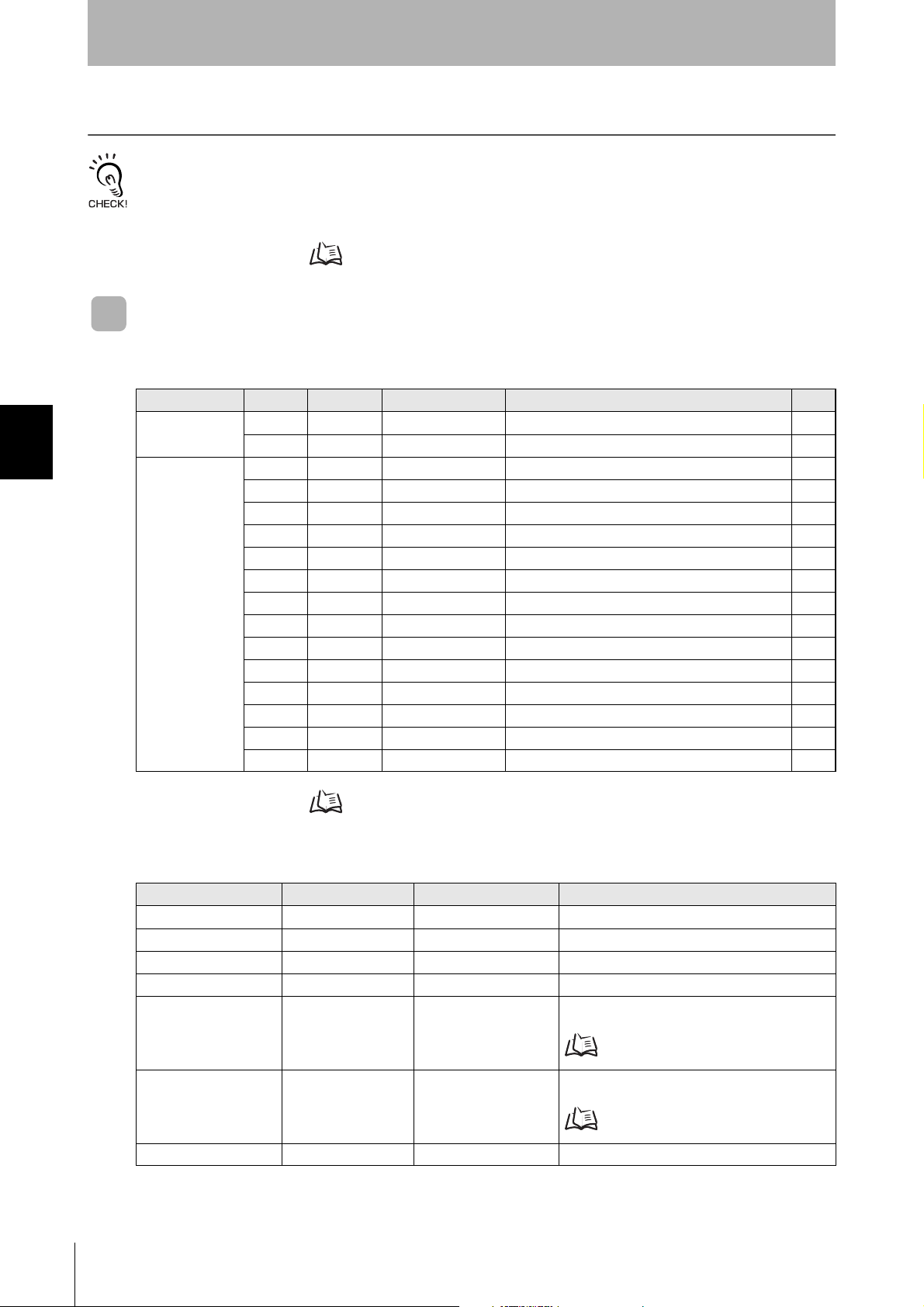
SECTION 4
Reading from/Writing to ID Tags
When SECS Is Used
The SEMI standards are subject to revision. You must refer to the actual standards.
• SEMI E99 THE CARRIER ID READER/WRITER FUNCTIONAL STANDARD
• SEMI E5 EQUIPMENT COMMUNICATION STANDARD 2 MESSAGE CONTENT (SECS II)
• SEMI E4 EQUIPMENT COMMUNICATION STANDARD 1 MESSAGE TRANSFER (SECS I)
SECS Protocol Specifications Refer to page 161.
Message Specifications
List of Messages Used
SECTION 4
When SECS Is Used
Classification S F Direction SECS II names See
General purpose
messages
CIDRW system
messages
List of Error Messages Refer to page 106.
11 S,H→E,reply Are You There Request p.78
12 S,H←E On Line Data p.78
18 1 S,H→E,reply Read Attribute Request p.78
18 2 S,H←E Read Attribute Data p.78
18 3 S,H→E,reply Write Attribute Request p.79
18 4 S,H←E Write Attribute Acknowledge p.79
18 5 S,H→E,reply Read Request p.80
18 6 S,H←E Read Data p.80
18 7 S,H→E,reply Write Request p.81
18 8 S,H←E Write Acknowledge p.81
18 9 S,H→E,reply Read ID Request p.82
18 10 S,H←E Read ID Data p.82
18 11 S,H→E,reply Write ID Request p.82
18 12 S,H←E Write ID Acknowledge p.83
18 13 S,H→E,reply Subsystem Command Request p.83
18 14 S,H←E Subsystem Command Acknowledge p.83
76
Data Item Dictionary
SECS II data items Name Format Valu e
ATTRID Attribute ID 20 Attribute name
ATTRVAL Attribute value 20 Attribute value
MID Carrier ID MID 20
DATA Data 20 All characters 00H-0FFH
DATALENGTH DataSize V700-L22: 52, V700-
DATASEG DataSeg 20 Offset designation: "00", "01"..."0222", "0223"
STATUS PM information 20 "NE": Normally executed
CIDRW System
User’s Manual
L22-V2: 51, 52, or 20
16 to 7E16 (Visible ASCII)
Offset designation: 1 to 224
Segment designation:
Refer to
Segment designation:
Refer to ID Tag Memory Maps page 159.
ID Tag Memory Maps page 159.
Page 79

Reading from/Writing to ID Tags
Data Item Dictionary
SECS II data items Name Format Valu e
SSACK Result status 20 "NO": Normal
"EE": Execution error *3
"CE": Communications error
"HE": Hardware error *3
"TE": Tag error *3
List of STATUS Status L,4
1.<PMInformation>
2.<AlarmStatus>
3.<OperationalStatus>
4.<HeadStatus> *2
CPVAL State request 20 V700-L22: "OP", "MT", "PS" *1
TARGETID Target ID 20 "00"-"31"
SSCMD Subsystem com-
mands
20 "ChangeState"
The STATUS values are included in the PM information.
V700-L22-V2: “OP”, “MT”, “PS”,*1 “CP”,*4
“ST”*4
"00" indicates the CIDRW Controller itself.
"GetStatus"
"PerformDiagnostics"
"Reset"
SECTION 4
SECTION 4
When SECS Is Used
*1: “PS” is an expansion command for this Unit.
*2: When the TARGET ID is "00" (CIDRW), this is a zero length item.
*3: "EE," "HE," and "TE" are used only with S18F6, S18F8, S18F10, and S18F12.
*4: “CP” and “ST” are expansion commands for this device and can be used only with the V700-L22-V2.
You can set unique state “CP” with the following SECS message.
1) CID Field(CID Max Length): T_CIDLEN
2) Segment name: T_SEGN
3) Segment length: T_SEGL
4) V700-L21 mode or V700-L22-V2 mode: RVER
5) The following timeout times:
RT (response timeout time)
S_T1 (timeout between characters)
S_T2 (protocol timeout)
S_T3 (response timeout)
S_T4 (timeout between characters)
S_RTY (retry limit)
After you set the parameter, send CPVAL = “ST” to confirm the parameter setting. The new value is enabled immediately.
S9F7 Responses
An S9F7 response is given when a message in an illegal format is received from the host device.
"Illegal format" here means that there is a problem with the message composition, such as illegal attributes, or insufficient or too many items. If other problems relating to the item contents arise, the response is SSACK = "CE" (communications error).
Communications with the Host Device
Communicate with the host device only after confirming that the CIDRW Controller has started. Also, unstable signals
may occur at the host interface when the CIDRW Controller is started. When initializing operation, clear the reception
buffer at the host device or take other suitable methods to clear unwanted signals.
CIDRW System
User’s Manual
77
Page 80

SECTION 4
Reading from/Writing to ID Tags
Specifications for Each Stream/Function
• Online Check
S1,F1 Are You There Request S,H→E,reply
S1,F2 On Line Data S,H←E
L,2
• Set MDLN (model number).
• Set SOFTREV (software revision level).
SECTION 4
• Get Attributes
S18,F1 Read Attribute Request S,H→E,reply
When SECS Is Used
L,2
• The setting for reading all attributes (CIDRW Controller or Heads) is n = 0.
Header only
1.<MDLN>
2.<SOFTREV>
1.<TARGETID> "00"-"31"
2.L,n
1.<ATTRID1>
⋅
n.<ATTRIDn>
S18,F2 Read Attribute Data S,H←E
L,4
1.<TARGETID> "00"-"31"
2.<SSACK>
3.L,n
1.<ATTRVAL1>
⋅
n.<ATTRVALn>
4.L,s
1.<STATUS1>
⋅
s.<STATUSs>
• The order of the attribute data corresponds to the attribute ID specified by S18, F1.
When reading of all attributes is specified, unsupported attribute items (ATTRVAL) are omitted.
• When the specified target is invalid:
n = 0, s = 0, SSACK = "CE" communications error
• When one or more undefined attributes are included:
n = 0, s = 0, SSACK = "CE" communications error
• When Head attributes are specified with TARGET = “00” or CIDRW Controller attributes are specified with TARGET <> “00”:
n = 0, s = 0, SSACK = “CE” communications error
• If the status of SSACK is other than "NO" (normal), the List of Status will comprise zero items.
78
CIDRW System
User’s Manual
Page 81

Reading from/Writing to ID Tags
• Set Attributes
F18,F3 Write Attribute Request S,H→E,reply
L,2
1.<TARGETID> "00" (fixed)
2.L,n
1.L,2
1.<ATTRID1>
2.<ATTRVAL1>
n.L,2
1.<ATTRIDn>
2,<ATTRVALn>
Since the attributes for Heads are all RO in this system, the target ID is fixed as “00”.
S18,F4 Write Attribute Acknowledge S,H←E
L,3
1.<TARGETID> "00" (fixed)
2.<SSACK>
3.L,s
1.<STATUS1>
⋅
s.<STATUSs>
• When the specified target is invalid:
s = 0, SSACK = "CE" communications error
• When one or more undefined attributes or RO attributes are included:
s = 0, SSACK = "CE" communications error
• When illegal attribute data is specified:
s = 0, SSACK = "CE" communications error
• If the status of SSACK is other than "NO" (normal), the List of Status will comprise zero items.
SECTION 4
SECTION 4
When SECS Is Used
CIDRW System
User’s Manual
79
Page 82

SECTION 4
Reading from/Writing to ID Tags
SECTION 4
• Read Data
S18,F5 Read Request S,H→E,reply
L,3
1.<TARGETID> "01"-"31"
2.<DATASEG>
3.<DATALENGTH>
• When DATASEG is specified as "0" and a character string, the size of data determined by the DATALENGTH setting is read,
starting from the address indicated by the DATASEG setting. If DATALENGTH = 0, data is read up to the end of the data
area.
• If DATASEG is specified as a character string, a size of data determined by DATALENGTH, starting from the address specified by DATASEG, is read (segment specification).
• When the data of all segments is batch read, both DATASEG and DATALENGTH are omitted (they are zero length items).
• When all the data for a particular segment is read, DATALENGTH is omitted (it is a zero length item).
• In a segment specification, it is not possible to specify a DATALENGTH that exceeds the maximum length of the relevant
DATASEG.
• In a segment specification, if a DATALENGTH that is under the set length for DATASEG is specified, only the data corresponding to specified DATALENGTH is read.
ID Tag Memory Maps Refer to page 159.
When SECS Is Used
S18,F6 Read Data S,H→E,reply
L,4
• When the specified target is invalid:
DATA item length = 0, s = 0, SSACK = "CE" communications error
• In an address specification, if:
(SEGMENT + DATALENGTH) ≤ total value for all segments then SSACK = "NO"
• In an address specification, if:
(SEGMENT + DATALENGTH) > total value for all segments then DATA item length = 0, s = 0, SSACK = "CE" communications error
• In a segment specification, if an undefined DATASEG is specified, or if the DATALENGTH is illegal:
DATA item length = 0, s = 0, SSACK = "CE" communications error
• When reading of all segment data is specified in a system where the data segment is not defined:
DATA length = 0, SSACK = "NO"
• If the status of SSACK is other than "NO" (normal), the List of Status will comprise zero items.
1.<TARGETID> "01"-"31"
2.<SSACK>
3.<DATA>
4.L,s
1.<STATUS1>
⋅
s.<STATUSs>
80
CIDRW System
User’s Manual
Page 83

SECTION 4
Reading from/Writing to ID Tags
• Write Data
S18,F7 Write Request S,H→E,reply
L,4
1.<TARGETID> "01"-"31"
2.<DATASEG>
3.<DATALENGTH>
4.<DATA>
• If DATASEG is specified as "0" and a character string, a size of data corresponding to the DATALENGTH setting and starting
from the address within the data area indicated by the DATASEG setting is written (address specification). If DATALENGTH
= 0, data is written up to the end of the data area.
• If DATASEG is specified as a character string, a size of data determined by DATALENGTH, starting from the address specified by DATASEG, is written (segment specification).
• When the data for all segments is batch written, both DATASEG and DATALENGTH are omitted (they are zero length items).
• When all the data for a particular segment is written, DATALENGTH is omitted (it is a zero length item).
• In a segment specification, it is not possible to specify a DATALENGTH that exceeds the maximum length of the relevant
DATASEG.
• In a segment specification, if a DATALENGTH that is under the set length for DATASEG is specified, only the data corresponding to the specified DATALENGTH is written, compressed into the smaller addresses.
• The item lengths of DATASEG and DATA must be matched.
• If DATASEG and DATALENGTH are both omitted (made zero length items), the length of DATA must match the total of the
set lengths of all segments.
SECTION 4
When SECS Is Used
ID Tag Memory Maps Refer to page 159.
S18,F8 Write Acknowledge S,H←E
L,3
1.<TARGETID> "01"-"31"
2.<SSACK>
3.L,s
1.<STATUS1>
⋅
s.<STATUSs>
• When the specified target is invalid:
s = 0, SSACK = "CE" communications error
• In an address specification, if:
(SEGMENT + DATALENGTH) ≤ total value for all segments then SSACK = "NO"
• In an address specification, if:
(SEGMENT + DATALENGTH) > total value for all segments then DATA item length = 0, s = 0, SSACK = "CE" (communications error)
• In a segment specification, if DATASEG and DATALENGTH are illegal:
s = 0, SSACK = "CE" communications error
• If the status of SSACK is other than "NO" (normal), the List of Status will comprise zero items.
CIDRW System
User’s Manual
81
Page 84

SECTION 4
Reading from/Writing to ID Tags
• Read ID
S18,F9 Read ID Request S,H→E,reply
1.<TARGETID> "01"-"31"
ID Tag Memory Maps Refer to page 159.
S18,F10 Read ID Data S,H←E
L,4
SECTION 4
• NVASC = “NOM”
1) If the MID data contains non-visible ASCII characters:
When SECS Is Used
2) If the MID data does not contain non-visible ASCII characters:
• NVASC = “ALL”
A normal response is returned even if the MID data contains non-visible ASCII characters.
• NVASC = “STD”
1) If the MID data does not contain visible ASCII characters:
2) If the MID data contains non-visible ASCII characters:
• NVASC = “EXT”
1) If the first data in the CID in the range defined by CIDOF and CIDLN is NULL, an “EE” execution error is returned.
2) If there are no visible ASCII characters between the start of the range defined by CIDOF and CIDLN and NULL, an “EE”
execution error is returned.
3) Any non-visible ASCII characters between the start of the range defined by CIDOF and CIDLN and NULL are deleted
and the MID is returned along with a normal response.
• When the specified target is invalid:
s = 0, MID item length = 0, SSACK = “CE” communications error
• If SSACK is not “NO” (normal), the List of Status will be a list structure of 0 items.
1.<TARGETID> "01"-"31"
2.<SSACK>
3.<MID>
4.L,s
1.<STATUS1>
⋅
s.<STATUSs>
s = 0, MID item length = 0, SSACK = “EE” execution error
Normal response
s = 0, MID item length = 0, SSACK = “EE” execution error
The non-visible ASCII characters are deleted and a normal response is returned.
82
The NVASC attribute can be used only with the V700-L22-V2.
With the V700-L22, if the MID data contains non-visible ASCII characters:
s = 0, MID item length = 0, SSACK = “EE” execution error
• Write ID
S18,F11 Write ID Request S,H→E,reply
L,2
• If an MID that is under the length set for the CarrierIDlength attribute is specified, an error occurs and the MID data is not
written.
ID Tag Memory Maps Refer to page 159.
CIDRW System
User’s Manual
1.<TARGETID> "01"-"31"
2.<MID>
Page 85

Reading from/Writing to ID Tags
S18,F12 Write ID Acknowledge S,H←E
L,3
1.<TARGETID> "01"-"31"
2.<SSACK>
3.L,s
1.<STATUS1>
⋅
s.<STATUSs>
• When the specified target is invalid:
s = 0, SSACK = "CE" communications error
• When there is an MID length error:
s = 0, SSACK = "CE" communications error
• If the MID data contains Non-Visible ASCII characters:
s = 0, SSACK = "EE" execution error
• If the status of SSACK is other than "NO" (normal), the List of Status will comprise zero items.
SECTION 4
SECTION 4
• Subsystem Command (ChangeState)
S18,F13 Subsystem Command Request (ChangeState) S,H→E,reply
L,3
1.<TARGETID> "00" (fixed)
2.<SSCMD> "ChangeState"
3.L,1
1.<CPVAL1> V700-L22: "OP", "MT", or
"PS"
V700-L22-V2: "OP", "MT",
"PS", "CP", or "ST"
• CPVAL = "PS" is a parameter setting unique to this CIDRW Controller for switching to the Setting mode.
• CPVAL1 = “CP” is a parameter unique to this CIDRW Controller that enables changing to a state to use SECS to change
parameters.
• CPVAL1 = “ST” is a parameter unique to this CIDRW Controller that validates values of parameters changed with the unique
“CP” mode.
S18,F14 Subsystem Command Acknowledge (ChangeState) S,H←E
L,3
1.<TARGETID> "00"
2.<SSACK>
3.L,s
1.<STATUS1>
⋅
s.<STATUSs>
• When the specified target is invalid:
s = 0, SSACK = "CE" communications error
• When SSCMD is invalid:
s = 0, SSACK = "CE" communications error
• When OperationalStatus is BUSY:
s = 0, SSACK = “EE” execution error
• If the status of SSACK is other than "NO" (normal), the List of Status will comprise zero items.
When SECS Is Used
CIDRW System
User’s Manual
83
Page 86

SECTION 4
Reading from/Writing to ID Tags
• Subsystem Command (GetStatus)
S18,F13 Subsystem Command Request (GetStatus) S,H→Ε,reply
L,3
S18,F14 Subsystem Command Acknowledge (GetStatus) S,H←E
L,3
SECTION 4
• When the specified target is invalid:
When SECS Is Used
s = 0, SSACK = “CE” communications error
• When SSCMD is invalid:
s = 0, SSACK = “CE” communications error
• If the status of SSACK is other than "NO" (normal), the List of Status will comprise zero items.
1.<TARGETID> "00"-"31"
2.<SSCMD> "GetStatus"
3.L,0
1.<TARGETID> "00"-"31"
2.<SSACK> "GetStatus"
3.L,s
1.<STATUS1>
⋅
s.<STATUSs>
• Subsystem Command (PerformDiagnostics)
S18,F13 Subsystem Command Request (PerformDiagnostics) S,H→E,reply
L,3
1.<TARGETID> "00"-"31"
2.<SSCMD> "PerformDiagnostics"
3.L,0
S18,F14 Subsystem command Acknowledge (PerformDiagnostics) S,H←E
L,3
1.<TARGETID> "00"-"31"
2.<SSACK>
3.L,s
1.<STATUS1>
⋅
s.<STATUSs>
• When the specified target is invalid:
s = 0, SSACK = “CE” communications error
• When SSCMD is invalid:
s = 0, SSACK = “CE” communications error
• If the status of SSACK is other than "NO" (normal), the List of Status will comprise zero items.
84
CIDRW System
User’s Manual
Page 87

Reading from/Writing to ID Tags
• Subsystem Command (Reset)
S18,F13 Subsystem Command Request (Reset) S,H→E,reply
L,3
1.<TARGETID> "00" (fixed)
2.<SSCMD> "Reset"
3.L,0
S18,F14 Subsystem Command Acknowledge (Reset) S,H←E
L,3
1.<TARGETID> "00"
2.<SSACK>
3.L,0
• When the specified target is invalid:
SSACK = “CE” communications error
• When SSCMD is invalid:
SSACK = “CE” communications error
SECTION 4
SECTION 4
Operation Conditions
The response messages and response codes (SSACK) in each state are shown below.
State
Message Function IDLE BUSY
S1,F1 OnlineRequest S1,F0 S1,F2 S1,F2 S1,F2
S18,F11 WriteID S18,F0 S18,F0 S18,F0 NO
S18,F7 WriteData S18,F0 NO NO S18,F0
S18,F3 SetAttribute S18,F0 NO NO NO
S18,F13(Reset) Reset S18,F0 NO NO NO
S18,F9 ReadID S18,F0 NO NO NO
S18,F5 ReadData S18,F0 NO NO S18,F0
S18,F13(PerformDiagnostics) Diagnostics S18,F0 NO NO NO
S18,F13(GetStatus) GetStatus S18,F0 NO NO NO
S18,F1 GetAttribute S18,F0 NO NO NO
S18,F13(ChangeState) ChangeState(to MT) S18,F0 NO S18,F0 S18,F0
S18,F13(ChangeState) ChangeState(to OP) S18,F0 S18,F0 S18,F0 NO
S18,F13(ChangeState) ChangeState(to PS) S18,F0 NO S18,F0 NO
Initializing
Operating
When SECS Is Used
Maintenance
CIDRW System
User’s Manual
85
Page 88

SECTION 4
Command
Calculation range
(ASCII conversion)
Reading from/Writing to ID Tags
When SECS Is Not Used
Command/Response Format
1:N Protocol
Command
SECTION 4
When SECS Is Not Used
SOH Node No. Command code
01h 0Dh
1 ⋅ ⋅ ⋅ n
Parameter
FCS CR
Response
SOH Node No.
01h 0Dh
Response
code
1 ⋅ ⋅ ⋅ n
Parameter
FCS CR
1:1 Protocol
Command
Command code
Response
Response
code
1 ⋅ ⋅ ⋅ n
Parameter
1 ⋅ ⋅ ⋅ n
Parameter
CR
0Dh
CR
0Dh
86
Meaning of FCS (frame check sequence)
This is two ASCII characters obtained by conversion from the 8-bit exclusive logical sum (EOR) of the characters from
the character immediately after SOH to the character immediately before FCS.
Example: Reading the data of page 1 and page 2 of node No.1
CIDRW System
User’s Manual
Page 89

SECTION 4
Reading from/Writing to ID Tags
Command
Command Code List
Name Va lue Function See
READ 0100 When this command is received, the system communicates with the ID Tag, and
reads the specified page(s) of data. Any pages up to a maximum of 16 can be
selected.
WRITE 0200 When this command is received, the system communicates with the ID Tag, and
writes the specified page(s) of data. Any pages up to a maximum of 16 can be
selected.
SAME WRITE 0300 When this command is received, the system communicates with the ID Tag, and
writes the same data in page units to the specified pages. Up to 17 pages, which is
the maximum number of pages for an ID Tag, can be specified.
BYTE WRITE 0400 When this command is received the system communicates with the ID Tag, and
writes data to the area specified by a first address and number of bytes. A maximum
of 128 bytes can be specified.
TEST 10 Sends received data to the host device. p.94
NAK 12 Sends the response made immediately before again. p.95
GET PARAMETER 14 Gets the model number, Firmware version, or another parameter. p.96
GET LAST COMMAND
GET COMMUNICATIONS HISTORY
CLEAR COMMUNICATIONS HISTORY
NOISE MEASUREMENT
RESET 7F Resets the Amplifier Unit. p.103
15 Gets the command code of the last command that was executed. p.99
16 Gets the history of communications from when the power was turned ON (total num-
ber of communications, total successful communications, and total number of failed
communications).
17 Clears the communications history. p.101
40 Measures the noise in the vicinity of the CIDRW Head. p.102
p.88
p.90
p.92
p.93
p.100
SECTION 4
When SECS Is Not Used
Response Code List
Type
Normal end 00 Normal end Command execution is completed normally.
Host communications error
Communications error
Communications with the Host Device
Communicate with the host device only after confirming that the CIDRW Controller has started. Also, unstable signals
may occur at the host interface when the CIDRW Controller is started. When initializing operation, clear the reception
buffer at the host device or take other suitable methods to clear unwanted signals.
Response
code
14 Format error There is a mistake in the command format. (For example, the command
70 Communications error Noise or another hindrance occurs during communications with an ID
71 Verification error Correct data cannot be written to an ID Tag.
72 No Tag error Either there is no ID Tag in front of the CIDRW Head, or the CIDRW
7B Outside write area error A write operation was not completed normally because the ID Tag was
7E ID system error (1) The ID Tag is in a status where it cannot execute command processing.
7F ID system error (2) An inapplicable ID Tag has been used.
Name Description
code is undefined, or the page or address specification is inappropriate.)
Tag, and communications cannot be completed normally.
Head is unable to detect the ID Tag due to environmental factors (e.g.,
noise).
in an area in which the ID Tag could be read but not written.
CIDRW System
User’s Manual
87
Page 90

SECTION 4
Bit 7 - 07- 321076 -1076 - 210
Page Sys - Sys Sys - Sys 17 16 15 14 13 - 8 7 6 5 - 1 Sys Sys
Designation 0* 0* 0* 0* 0* 0/1 0/1 0/1 0/1 0/1 ••• 0/1 0/1 0/1 0/1 ••• 0/1 0* 0*
Value 00 00 to 07 00 to FF 00 to FC
* Always specify 0. If you specify 1 an error (Response code: 14) will occur.
SOH Node No. Command code Page designation (8 characters) FCS CR
01h 0100 0Dh
Reading from/Writing to ID Tags
The command and response details are given for a 1:N protocol. Just as in the previous command format, the
details for a 1:1 protocol are the same if the SOH, node number, and FCS are deleted.
Command
SECTION 4
READ
Reads any pages of data from the ID Tag. The maximum number of pages that can be read at one time
is 16.
When SECS Is Not Used
Parameter Description
Parameter Description
Page designation Pages are specified by setting the bits corresponding to pages that are to be read to 1 and setting
the other bits to 0, then converting the result to a hexadecimal character string.
ID Tag Memory Maps Refer to page 159.
The response code (when normal: 00) and the data in the specified pages are returned in ascending order of
page numbers.
Response
SOH Node No.
01h 0 0 0Dh
Response
code
Data 1 ⋅ ⋅ ⋅ Data 8 Data 1 ⋅ ⋅ ⋅ Data 8
Read data
⋅ ⋅ ⋅
Page m (n<m)
FCS CRPage n
88
CIDRW System
User’s Manual
Page 91

Example: Reading the data of pages 1 and 3 of node No.1
Command
00000000000000000000000000010100
Binary notation
SOH Node No. Command code Page designation FCS CR
01h01010000000014050Dh
Data Content of the ID Tag
Page 1 12h 34h 56h 78h 90h 12h 34h 56h
Page 2
Page 3 11h 22h 33h 44h 55h 66h 77h 88h
Page 4
SECTION 4
Reading from/Writing to ID Tags
SECTION 4
Response
SOH Node No.
01h010012345678901234561122334455667788070Dh
Response
code
If you send a “Read“ command that specified 1 to 2 page to a 1-page only ID Tag, the Amplifier Unit will response 2nd
page data as all zero.
Page 1 Page 3 FCS CR
When SECS Is Not Used
CIDRW System
User’s Manual
89
Page 92

SECTION 4
Bit 7 - 07- 321076 -1076 - 210
Page Sys - Sys Sys - Sys 17 16 15 14 13 - 8 7 6 5 - 1 Sys Sys
Designation 0* 0* 0* 0* 0* 0/1 0/1 0/1 0/1 0/1 ••• 0/1 0/1 0/1 0/1 ••• 0/1 0* 0*
Value 00 00 to 07 00 to FF 00 to FC
* Always specify 0. If you specify 1 an error (Response code: 14) will occur.
SOH
Node
No.
Command
code
Page designation
(8 characters)
Write data
FCS CRPage n
⋅ ⋅ ⋅
Page m (n<m)
Data 1 ⋅ ⋅ ⋅ Data 8 Data 1 ⋅ ⋅ ⋅ Data 8
01h 0200 0DH
Reading from/Writing to ID Tags
Command
SECTION 4
WRITE
Data is written in page units to the ID Tag. Any page(s) can be specified. It is possible to write to a maximum of 16 pages at one time.
When SECS Is Not Used
Parameter Description
Parameter Description
Page designation Pages are specified by setting the bits corresponding to pages that are to be read to 1 and setting
the other bits to 0, then converting the result to a hexadecimal character string.
Write data The data to be written to the specified pages is specified in ascending order of page numbers.
ID Tag Memory Maps Refer to page 159.
Response
The response code (when normal: 00) is returned.
SOH Node No.
01h 0 0 0Dh
Response
code
FCS CR
90
CIDRW System
User’s Manual
Page 93

Example: Writing data to pages 8 and 10 of node No.1
Command
00000000000000000000101000000000
SOH
Node
No.
Command
code
Page designation Data of page 8 Data of page 10 FCS CR
01h 0 1 0 2 0 000000A0011223344556677880123456789ABCDEF 7 4 0Dh
Binary notation
Response
SOH Node No.
01h0100010Dh
Response
code
FCS CR
SECTION 4
Reading from/Writing to ID Tags
SECTION 4
When SECS Is Not Used
The ID Tag status on normal completion is as shown below.
Page 8 11h 22h 33h 44h 55h 66h 77h 88h
Page 9
Page 10 01h 23h 45h 67h 89h ABh CDh EFh
CIDRW System
User’s Manual
91
Page 94

SECTION 4
SOH Node No. Command code Page designation (8 characters)
Write data
FCS CR
Data 1 ⋅ ⋅ ⋅ Data 8
01h 0 3 0 0 0DH
Bit 7 - 07- 321076 -1076 - 210
Page Sys - Sys Sys - Sys 17 16 15 14 13 - 8 7 6 5 - 1 Sys Sys
Designation 0* 0* 0* 0* 0* 0/1 0/1 0/1 0/1 0/1 ••• 0/1 0/1 0/1 0/1 ••• 0/1 0* 0*
Value 00 00 to 07 00 to FF 00 to FC
* Always specify 0. If you specify 1 an error (Response code: 14) will occur.
00000000000001111111111111111100
Binary notation
SOH Node No.
Command
code
Page designation Write data FCS CR
01h 0 1 03000007FFFC0000000000000000 0 0 0Dh
Reading from/Writing to ID Tags
Command
SECTION 4
SAME WRITE
This command writes the same data to multiple pages of an ID Tag. Any page(s) can be specified.
When SECS Is Not Used
Parameter Description
Parameter Description
Page designation Pages are specified by setting the bits corresponding to pages that are to be read to 1 and setting
the other bits to 0, then converting the result to a hexadecimal character string.
Write data Specify the write data.
ID Tag Memory Maps Refer to page 159.
Response
The response code (when normal: 00) is returned.
SOH Node No.
01h 0 0 0Dh
Response
code
FCS CR
Example: Clearing pages 1 to 17 of node No.1 to 0
Command
92
Response
SOH Node No.
01h0100010Dh
CIDRW System
User’s Manual
Response
code
FCS CR
Page 95

Reading from/Writing to ID Tags
BYTE WRITE
This command writes data to any specified number of bytes starting from the address specified in the
ID Tag. The maximum number of bytes that can be written at one time is 128.
Command
SOH Node No. Command code
01h 0400 0Dh
* Data number n = number of bytes written to (2-character units)
First
address
Data 1 ••• Data n
Parameter Description
Parameter Description
First address Addresses can be specified in the range 00h to 87h.
Write data Up to 128 bytes of write data, starting from the specified address, can be specified.
Write data
FCS CR
SECTION 4
SECTION 4
ID Tag Memory Maps Refer to page 159.
Response
The response code (when normal: 00) is returned.
SOH Node No.
01h 0 0 0Dh
Response
code
FCS CR
Example: Writing to two bytes starting from address 05h of node No.1
Command
SOH Node No. Command code First address
01h010400051234040Dh
Write data
Data 1 Data 2
FCS CR
When SECS Is Not Used
Response
SOH Node No.
01h0100010Dh
Response
code
FCS CR
The ID Tag status on normal completion is as shown below.
Page 1 12h 34h
Page 2
CIDRW System
User’s Manual
93
Page 96

SECTION 4
Reading from/Writing to ID Tags
TEST
Performs a communications test on communications between the host device and Amplifier Unit.
When an Amplifier Unit receives a test command, it sends the response code and command test data
to the host device as the response.
Command
SOH Node No. Command code
01h 1 0 0Dh
* Number of data n < 136 (2-character units)
Data 1 ••• Data n
Test data
FCS CR
SECTION 4
When SECS Is Not Used
Response
The response code (when normal: 00) and the received test data are returned.
SOH Node No.
01h 0 0 0Dh
Command
SOH Node No. Command code
01h01 1 0 12345678080Dh
Parameter Description
Parameter Description
Test data The data to be sent in the test is specified with a hexadecimal value. (270 characters max.)
However, note that odd numbers of characters cannot be used.
Response
code
Data 1 ••• Data n
Test data
FCS CR
Example: Testing by sending the data 12345678 to node No.1
Test data
Data 1 Data 2 Data 3 Data 4
FCS CR
94
Response
SOH Node No.
01h010012345678090Dh
CIDRW System
User’s Manual
Response
code
Data 1 Data 2 Data 3 Data 4
Test data
FCS CR
Page 97

NAK
Sends the response made immediately before again.
Command
SOH Node No. Command code FCS CR
01h 1 2 0Dh
Response
Sends the response made immediately before again.
SECTION 4
Reading from/Writing to ID Tags
SECTION 4
When SECS Is Not Used
CIDRW System
User’s Manual
95
Page 98

SECTION 4
Reading from/Writing to ID Tags
Command
SOH Node No. Command code Parameter type FCS CR
01h 1 4 0Dh
SECTION 4
When SECS Is Not Used
GET PARAMETER
This command gets the model number, firmware version, or another parameter.
Parameter Description
Parameter Va lue Description
Parameter type 01 Model number
02 Firmware version
20 Memory status
21 Antenna connection status
Response
The response code (00: normal) and received parameter value are returned.
SOH Node No.
01h 0 0 0Dh
* The contents and length of the parameter value depend on the parameter type that is specified for the command.
Response
code
Parameter value FCS CR
Example 1: Getting the Model Number of Node 1
Command
SOH Node No. Command code
01h 0 1 1 4 0 1 0 5 0Dh
Parameter
type
FCS CR
Response
The product model number is returned as an ASCII text string.
96
SOH Node No.
01h 0 1 0 0 V640-HAM11-V3 4 4 0Dh
CIDRW System
User’s Manual
Response
code
Model number FCS CR
Page 99

Reading from/Writing to ID Tags
SOH Node No. Response code Firmware version FCS CR
01h01 0 0 0100000Dh
Major version
Minor version
Example 2: Getting the Firmware Version of Node 1
Command
SOH Node No. Command code
01h 0 1 1 4 0 2 0 6 0Dh
Parameter
type
FCS CR
Response
The response code (00: normal) and firmware version are returned as a 4-digit decimal number.
* The above response is for a firmware version of 1.00.
SECTION 4
SECTION 4
When SECS Is Not Used
CIDRW System
User’s Manual
97
Page 100

SECTION 4
Command
Response
Reading from/Writing to ID Tags
Example 3: Getting the Memory Status of Node 1
SOH Node No. Command code
01h 0 1 1 4 2 0 0 6 0Dh
The response code (00: normal) and memory check results for internal EEPROM are returned.
SOH Node No.
SECTION 4
01h0100 000Dh
When SECS Is Not Used
Command
SOH Node No. Command code
01h 0 1 1 4 2 1 0 7 0Dh
Parameter
type
Response
code
* “Memory status” will be if the memory is normal:”01”, and is error:”00”.
Memory status FCS CR
FCS CR
Example 4: Getting the Antenna Connection Status of Node 1
Parameter
type
FCS CR
Response
The response code (00: normal) and Antenna connection status are returned.
SOH Node No.
01h0100 000Dh
* “Antenna connection status” will be if the antenna is connected correctly:”01”, and is not correctly:”00”.
Response
code
Antenna connec-
tion status
FCS CR
98
CIDRW System
User’s Manual
 Loading...