

Page 1
RFID System
V680S Series
User’s Manual
(Modbus TCP)
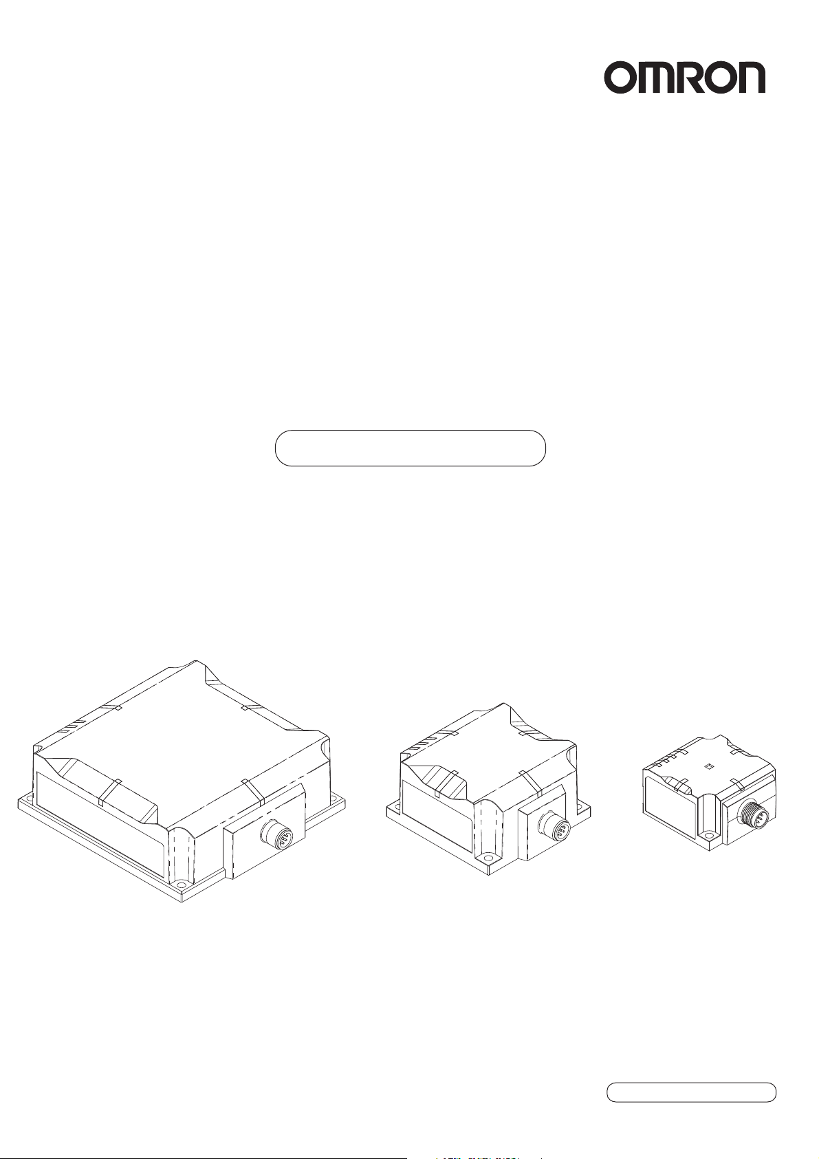
Reader/Writer
V680S-HMD63-ETN
V680S-HMD64-ETN
V680S-HMD66-ETN
Man. No. Z339-E1-13
Page 2

Introduction
Thank you for purchasing a V680S-series RFID System. This manual describes the functions,
performance, and application methods needed for optimum use of the V680S-series RFID System.
Please observe the following items when using the V680S-series RFID System.
• Allow the V680S-series RFID System to be installed and operated only by qualified specialists
with a sufficient knowledge of electrical systems.
• Read and understand this manual before attempting to use the RFID System and use the RFID
System correctly.
• Keep this manual in a safe and accessible location so that it is available for reference when
required.
NOTICE
(1) No part of this publication may be reproduced, stored in a retrieval system, or transmitted, in any
form, or by any means, mechanical, electronic, photocopying, recording, or otherwise, without the
prior written permission of OMRON.
(2) Because OMRON is constantly striving to improve its high-quality products, the information
contained in this manual is subject to change without notice.
(3) Every precaution has been taken in the preparation of this manual. Nevertheless, OMRON
assumes no responsibility for errors or omissions. Neither is any liability assumed for damages
resulting from the use of the information contained in this publication. If you find any problems in
this manual, please contact your OMRON representative. If you do so, please provide the Cat. No.
that is given at the back of this manual.
Trademarks
• Microsoft, Windows, Edge, Internet Explorer are either registered trademarks or trademarks of
Microsoft Corporation in the USA and other countries.
• ODVA and EtherNet/IP are trademarks of the ODVA.
• Google Chrome is trademarks or registered trademarks of Google LLC.
Other system names and product names used in this manual are the trademarks or registered
trademarks of the respective companies.
Page 3

Introduction
Section 1
Section 2
Section 3
Section 4
Section 5
Section 6
Section 7
Section8
Section9
Section10
Section11
Terms and Conditions Agreement (Always Read This Information)
Product Overview
System Configuration
Component Names
Installation and Connections
Preparations for Communications
Introduction
Section 1 Section 2 Section 3 Section 4 Section 5 Section 6 Section 7 Section 8 Section 9
Functions
Host Communications Specifications
Web Browser Interface
Troubleshooting
Maintenance and Inspection
Appendices
Section 10 Section 11
RFID System
V680S-HMD63-ETN Reader/Writer
V680S-HMD64-ETN Reader/Writer
V680S-HMD66-ETN Reader/Writer
User's Manual
Page 4

Introduction
Introduction
Terms and Conditions Agreement
Warranty, Limitations of Liability
1. Warranties
Exclusive Warranty
Omron’s exclusive warranty is that the Products will be free from defects in materials and workmanship
for a period of twelve months from the date of sale by Omron (or such other period expressed in writing
by Omron). Omron disclaims all other warranties, express or implied.
Limitations
OMRON MAKES NO WARRANTY OR REPRESENTATION, EXPRESS OR IMPLIED, ABOUT NON-
INFRINGEMENT, MERCHANTABILITY OR FITNESS FOR A PARTICULAR PURPOSE OF THE
PRODUCTS. BUYER ACKNOWLEDGES THAT IT ALONE HAS DETERMINED THAT THE
PRODUCTS WILL SUITABLY MEET THE REQUIREMENTS OF THEIR INTENDED USE.
Omron further disclaims all warranties and responsibility of any type for claims or expenses based on
infringement by the Products or otherwise of any intellectual property right.
Buyer Remedy
Omron’s sole obligation hereunder shall be, at Omron’s election, to (i) replace (in the form originally
shipped with Buyer responsible for labor charges for removal or replacement thereof) the non-
complying Product, (ii) repair the non-complying Product, or (iii) repay or credit Buyer an amount equal
to the purchase price of the non-complying Product; provided that in no event shall Omron be
responsible for warranty, repair, indemnity or any other claims or expenses regarding the Products
unless Omron’s analysis confirms that the Products were properly handled, stored, installed and
maintained and not subject to contamination, abuse, misuse or inappropriate modification. Return of
any Products by Buyer must be approved in writing by Omron before shipment. Omron Companies
shall not be liable for the suitability or unsuitability or the results from the use of Products in
combination with any electrical or electronic components, circuits, system assemblies or any other
materials or substances or environments. Any advice, recommendations or information given orally or
in writing, are not to be construed as an amendment or addition to the above warranty.
See http://www.omron.com/global/ or contact your Omron representative for published information.
2. Limitation on Liability; Etc
OMRON COMPANIES SHALL NOT BE LIABLE FOR SPECIAL, INDIRECT, INCIDENTAL, OR
CONSEQUENTIAL
DAMAGES, LOSS OF PROFITS OR PRODUCTION OR COMMERCIAL LOSS IN ANY WAY
CONNECTED WITH THE PRODUCTS, WHETHER SUCH CLAIM IS BASED IN CONTRACT,
WARRANTY, NEGLIGENCE OR STRICT LIABILITY.
Further, in no event shall liability of Omron Companies exceed the individual price of the Product on
which liability is asserted.
RFID System
2
User's Manual
(Modbus TCP)
Page 5

Application Considerationst
1. Suitability of Use
Omron Companies shall not be responsible for conformity with any standards, codes or regulations
which apply to the combination of the Product in the Buyer’s application or use of the Product. At
Buyer’s request, Omron will provide applicable third party certification documents identifying ratings
and limitations of use which apply to the Product. This information by itself is not sufficient for a
complete determination of the suitability of the Product in combination with the end product, machine,
system, or other application or use. Buyer shall be solely responsible for determining appropriateness
of the particular Product with respect to Buyer’s application, product or system. Buyer shall take
application responsibility in all cases.
NEVER USE THE PRODUCT FOR AN APPLICATION INVOLVING SERIOUS RISK TO LIFE OR
PROPERTY WITHOUT ENSURING THAT THE SYSTEM AS A WHOLE HAS BEEN DESIGNED TO
ADDRESS THE RISKS, AND THAT THE OMRON PRODUCT(S) IS PROPERLY RATED AND
INSTALLED FOR THE INTENDED USE WITHIN THE OVERALL EQUIPMENT OR SYSTEM.
2. Programmable Products
Omron Companies shall not be responsible for the user’s programming of a programmable Product, or
any consequence thereof.
Introduction
Introduction
Disclaimers
1. Performance Data
Data presented in Omron Company websites, catalogs and other materials is provided as a guide for
the user in determining suitability and does not constitute a warranty. It may represent the result of
Omron’s test conditions, and the user must correlate it to actual application requirements. Actual
performance is subject to the Omron’s Warranty and Limitations of Liability.
2. Change in Specifications
Product specifications and accessories may be changed at any time based on improvements and other
reasons. It is our practice to change part numbers when published ratings or features are changed, or
when significant construction changes are made. However, some specifications of the Product may be
changed without any notice. When in doubt, special part numbers may be assigned to fix or establish
key specifications for your application. Please consult with your Omron’s representative at any time to
confirm actual specifications of purchased Product.
3. Errors and Omissions
Information presented by Omron Companies has been checked and is believed to be accurate;
however, no responsibility is assumed for clerical, typographical or proofreading errors or omissions.
RFID System
User's Manual
(Modbus TCP)
3
Page 6

Introduction
Introduction
Precautions for Safe Use
Observe the following precautions to ensure safe use of the Product.
1. Installation and Storage Environment
• Do not install the Product near any equipment that generates a large amount of heat (such as
heaters, transformers, and large-capacity resistors).
• If multiple Reader/Writers are installed near each other, communications performance may decrease
due to mutual interference. Refer to
Installation Precautions
between Reader/Writers.
in Section 11 Appendices and check to make sure there is no mutual interference
2. Installation and Removal
• Never use an AC power supply. Doing so may result in rupture.
• Wire the Product correctly. Incorrect wiring may result in rupture or burning.
• Use a device supporting STP cables for the host device (such as a Switching Hub or PLC) which is
connected the specified Cables (V680S-A41 @M/-A42 @M/-A51 @M). Ground the host device to a
ground resistance of 100 Ω or less.
• Use one of the specified Cables (V680S-A40 @M/-A41 @M/-A42 @M/-A50 @M/-A51 @M). Using any
other cable may cause malfunctions or failure.
• The communications range is adversely affected if there is any metal material around the RF Tag.
• Transmission will not be possible if the front and back panels are mistakenly reversed and the Unit is
mounted to a metallic surface.
V680-D1KP66MT
V680S-D2KF67M/-D8KF67M
V680S-D2KF68M/-D8KF68M
• The transmission distancewill be reduced when the Unit is not mounted to a metallic surface.
V680-D1KP66MT
V680S-D2KF67M/-D8KF67M
V680S-D2KF68M/-D8KF68M
• The maximum communications range can be obtained when the Antenna faces the RF tag directly.
When the RF tag is installed at a tilt, the communications range is reduced. Consider the effect of the
RF tag at tilt when installing the RF Tag.
• Provide the mounting distances between plural RF tags to prevent them from malfunctions due to
mutual interference.
• if the central axis of an antenna and RF tag shifts, a communications range will fall.
• Do not touch the product immediately after usage at high temperatures, Doing so may occasionally
result in burning.
Mutual Interference of Reader/Writers (for Reference Only) in RF Tag
3. Application Methods
• Do not bend the Cable to a bending radius of 40 mm or less. Doing so may break the wires.
• If an error is detected in the Product, immediately stop operation and turn OFF the power supply.
Consult with an OMRON representative.
RFID System
4
User's Manual
(Modbus TCP)
Page 7

4. Cleaning
• Do not clean the Product with paint thinner, benzene, acetone, or kerosene.
5. Disposal
• Dispose of the Product as industrial waste.
Introduction
Introduction
RFID System
User's Manual
(Modbus TCP)
5
Page 8

Introduction
Introduction
Precautions for Correct Use
Always observe the following precautions to prevent operation failures, malfunctions, and adverse effects on
performance and equipment.
1. Installation and Storage Environment
Do not use or store the Product in the following locations.
• Locations subject to combustible gases, explosive gases, corrosive gases, dust, dirt, metal powder,
or salt
• Locations where the specified ambient temperature range or ambient humidity range is exceeded
• Locations subject to extreme temperature changes that may result in condensation
• Locations subject to direct vibration or shock outside the specified ranges
2. Installation
• This Product uses a frequency band of 13.56 MHz to communicate with RF Tags. Some transceivers,
motors, inverters, switch-mode power supplies, and other devices generate electrical noise that will
affect these communications. If any of these devices are located in the vicinity of the Product, they
may affect communications with RF Tags, and may possibly damage the RF Tags. Prior to using the
Product in the vicinity of any of these devices, perform a test to determine whether the Product can
be used under the resulting influence.
• Connect the control signal to the positive and negative sides of the power supply.
The control signal is used to change the operation mode of the Reader/Writer.
Refer to Connecting the V680S-A41@M/-A51@M Cable to the Host Device in Section 4 Installation and Connections for the
connector method.
p.90
• Do not exceed the rated voltage range. Doing so may result in Product destruction or burning.
• Tighten the mounting screws to a torque of 1.2 N·m.
• Tighten the Cable connector to a torque of 0.39 to 0.49 N·m.
3. Application Methods
• Do not drop the Product.
• Do not pull on the Cables with excessive force.
• Do not attempt to disassemble, repair, or modify the Product.
4. Maintenance
• Perform inspections both daily and periodically.
Refer to Maintenance and Inspection in Section 10 Maintenance and Inspection for the items to inspect.
p.264
5. Others
• When using V680S-HMD66-ETN, Install the ferrite core of the attachment to the exclusive cable as
model V680S-A41 @M/-A42 @M/-A51 @M.
RFID System
6
User's Manual
(Modbus TCP)
Page 9

Meanings of Symbols
Indicates particularly important points related to a function, including precautions and application advice.
Indicates page numbers containing relevant information.
Indicates reference to helpful information and explanations for difficult terminology.
Introduction
Introduction
RFID System
User's Manual
(Modbus TCP)
7
Page 10

Introduction
Introduction
Table of Contents
Introduction 1
Precautions for Safe Use 4
Precautions for Correct Use 6
Meanings of Symbols 7
Table of Contents 8
Section 1 Product Overview 15
Features 16
Application Flowchart 20
Product Specifications 27
Reader/Writer 27
Connector Cover (Standard Type) 30
Connector Cover (Slim Type) 32
Extension Cable 33
Cables 34
RF Tag 36
Data Characteristics 48
Communications Range Specifications 48
Section 2 System Configuration 57
System Configuration 58
Section 3 Component Names 63
Component Names 64
Reader/Writer 64
Cables 66
RF Tag 68
RFID System
8
User's Manual
(Modbus TCP)
Page 11

Introduction
Section 4 Installation and Connections 71
Installation 72
Reader/Writer 72
Connector Cover 75
RF Tag 80
Connections and Wiring 87
Connecting and Removing the Reader/Writer Cable 87
Attaching Ferrite Core 89
Connecting the V680S-A41@M/-A51@M Cable to the Host Device 90
Extending the Cable 91
Assembling and Connecting the V680S-A42@M Cable and Connector 92
Introduction
Section 5 Preparations for Communications 93
Starting the Reader/Writer 94
Reader/Writer Starting Procedure 94
Setting Communications Conditions 95
Preparations for Work 95
Setting the IP Address of the Reader/Writer from a Web Browser 97
Setting Procedure for Modbus Queries from the Host Device 99
Section 6 Functions 101
Operation Mode 102
Run Mode 102
Safe Mode 102
RF Tag Communications 103
Communications Options 103
Normal RF Tag Communications 107
Tag Memory Management 107
Reader/Writer Controls 109
STOP Query 109
RESET Query 109
Maintenance 110
Noise monitor 110
GET LOG INFORMATION Query 110
RFID System
User's Manual
(Modbus TCP)
9
Page 12

Introduction
Introduction
Setting Queries 111
Setting Controls 111
SET TAG COMMUNICATIONS CONDITIONS Query 112
Setting Host Device Communications Conditions 113
Error Logs 114
System Error Log 114
Communications Error Log 115
Recent Error Query Log 116
Web Server 117
Status Monitoring, Setting, and Confirmation 117
Convenient Functions 117
RFID System Maintenance 118
Communication Diagnostic 118
RF Analyzer 121
Multi-Reader/Writer Operation 123
Field Extension Mode 126
High-speed Traveling Mode 127
Using Communication Diagnostic and the RF Analyzer 129
Using the Web Server 129
Using Modbus Queries for Communication Diagnostic 135
Using Field Extension Mode 138
Using Field Extension Mode 138
Using High-speed Traveling Mode 147
Section 7 Host Communications Specifications 157
Modbus Communications Protocol 158
Message Formats 159
Function Code Descriptions 162
Error Handling 164
10
Query Tables 165
Exception Code Table 167
Message Details 170
RF Tag Communications 170
Reader/Writer Settings 179
Checking Reader/Writer Information 192
Controlling Reader/Writer Operation 204
RFID System Maintenance 208
Initializing All Settings 216
RFID System
User's Manual
(Modbus TCP)
Page 13

Introduction
Section 8 Web Browser Interface 217
Web Browser Operation Window 218
Operation Interface 220
Password Entry View 220
Status View 221
Network Settings View 222
Communications Settings View 224
SET MULTI-READER/WRITER OPERATION 225
RF Tag Communications View 226
Log View 228
Noise Monitor View 229
RF Analyzer 230
Reboot 234
Introduction
Configuration 235
Configuration File 239
Section 9 Troubleshooting 241
Error Descriptions 242
Fatal Errors 242
Nonfatal Errors 242
Errors and Indicator Status 243
Fatal Errors 243
Nonfatal Errors 245
Errors and Countermeasures 246
Reader/Writer Operation Errors 246
IP Address Duplication Error 247
System Errors 247
V680S Query Errors 249
RF Tag Communications Errors 250
Troubleshooting Flowcharts 251
Main Check Flowchart 251
System Connections Check Flowchart 252
Operating Conditions and External Environment Check Flowchart 253
Host Device Communications Check Flowchart 254
RF Tag Communications Check Flow 255
About The Ethernet Communication Abnormality 256
RFID System
User's Manual
(Modbus TCP)
11
Page 14

Introduction
Introduction
When the Web browser screen is not displayed or the screen layout is strange 257
Google Chrome 257
Internet explorer11 259
Microsoft Edge 260
Safe Mode 262
Starting in Safe Mode 262
Section 10 Maintenance and Inspection 263
Maintenance and Inspection 264
Section 11 Appendices 265
Data Characteristics 266
RF Tag Communications Range (for Reference Only) 266
RF Tag Communications Time (for Reference Only) 274
Reader/Writer Installation Precautions 278
V680S-HMD63-ETN 278
V680S-HMD64-ETN 279
V680S-HMD66-ETN 281
RF Tag Installation Precautions 283
V680-D1KP54T 283
V680-D1KP66T 286
V680-D1KP66MT 289
V680-D1KP66T-SP 292
V680-D1KP58HTN 296
V680S-D2KF67 298
V680S-D2KF67M 301
V680S-D8KF67 304
V680S-D8KF67M 307
12
V680S-D2KF68 310
V680S-D2KF68M 313
V680S-D8KF68 316
V680S-D8KF68M 319
RF Tag Memory Capacities and Memory Types 322
RF Tag Memory Map 323
Chemical Resistance of the Reader/Writers and RF Tags 326
Degree of Protection 330
Differences in Address and Size Specifications between V680 and V680S Reader/Writers 332
RFID System
User's Manual
(Modbus TCP)
Page 15

Introduction
Index 335
Revision History 338
Firmware Version Update History 339
Introduction
RFID System
User's Manual
(Modbus TCP)
13
Page 16

Introduction
Introduction
MEMO
14
RFID System
User's Manual
(Modbus TCP)
Page 17
Section 1 Product Overview
Features 16
Application Flowchart 20
Product Specifications 27
Reader/Writer 27
Connector Cover (Standard Type) 30
Connector Cover (Slim Type) 32
Extension Cable 33
Cables 34
RF Tag 36
Data Characteristics 48
Communications Range Specifications 48
Section 1 Product Overview
RFID System
User's Manual
(Modbus TCP)
15
Page 18
Section 1
PLC
Antenna
PLC
Amplifier
ID Controller
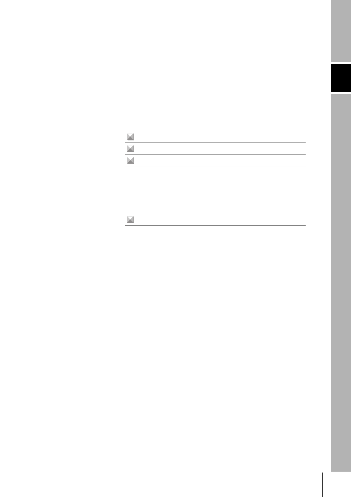
Previous OMRON Models
V680S Integrated Reader/Writer
24-VDC
power supply
24-VDC
power supply
Reader/Writer
40
60
80
20
100
Y
-100 -80 -60 -40 -20 0 20 40 60 80X
Y
X
Read
Write
Product Overview
Features
Section 1 Features
The integrated V680S-series Reader/Writers (V680S-HMD6@-ETN) perform communications with RF Tags
according to query from a host device.
Integrated Structure
The controller, amplifier, and antenna are integrated into the Reader/Writer for a simple structure.
Simple Installation
The Reader/Writer is automatically set to the best parameters according to the RF Tags to achieve
stable communications with more consistent communications and less omissions of RF Tags in the
communications field.
16
RFID System
User's Manual
(Modbus TCP)
Page 19
Section 1
Product Overview
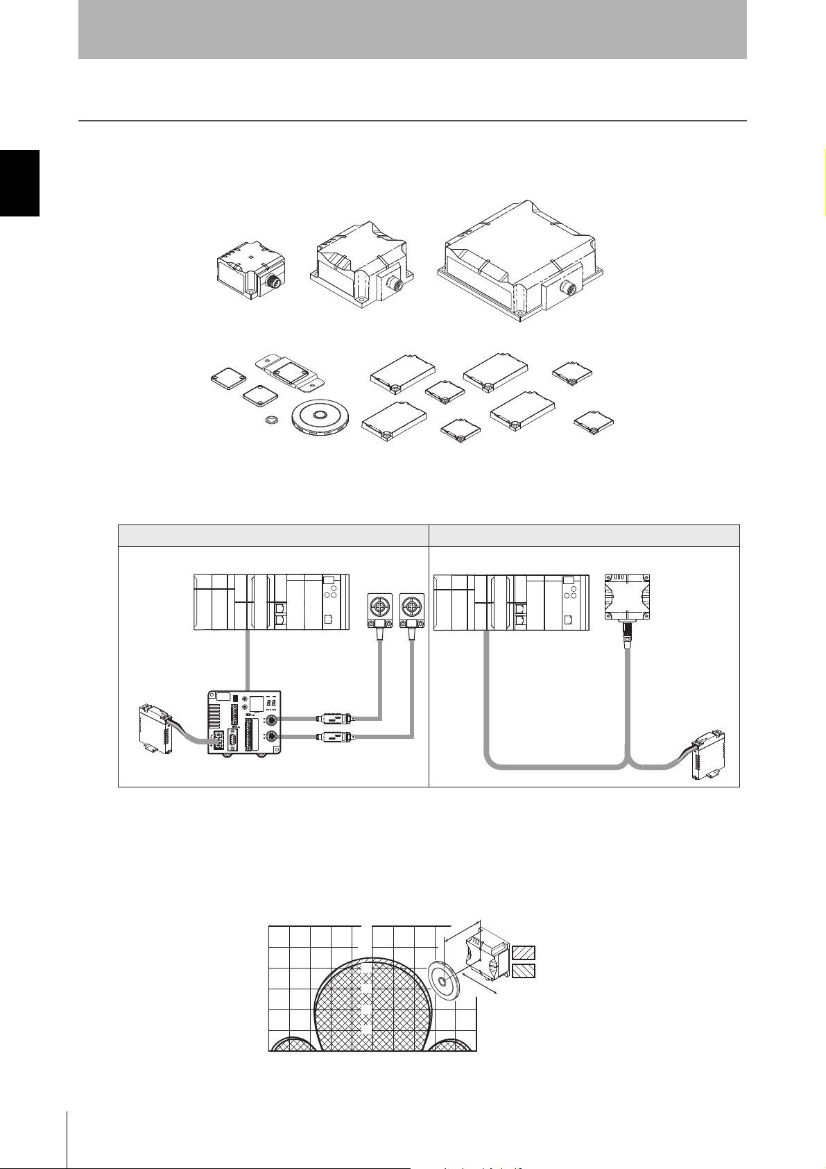
Stable Operation
When the Reader/Writer communicates with an RF Tag, it diagnoses the communications leeway and
reports the result. You can check the communications leeway to appropriately install the Reader/Writer
and RF Tags to achieve stable operation of your OMRON RFID System.
You can use communications leeway diagnosis with Reader/Writers with firmware version 2.00 or higher.
For details, refer to Using Communication Diagnostic and the RF Analyzer in Section 6 Functions.
p.129
If you use the RFID System under installation conditions that provide a high communications leeway,
you can reduce communications troubles during system operation and achieve stable line operation.
Area of stable communications
Area of unstable communications
Area of stable communications
Area of unstable communications
Area of stable communications
Area of unstable communications
Section 1 Features
Operation Indicator lights green Operation Indicator lights yellow Operation Indicator lights red
RFID System
User's Manual
(Modbus TCP)
17
Page 20
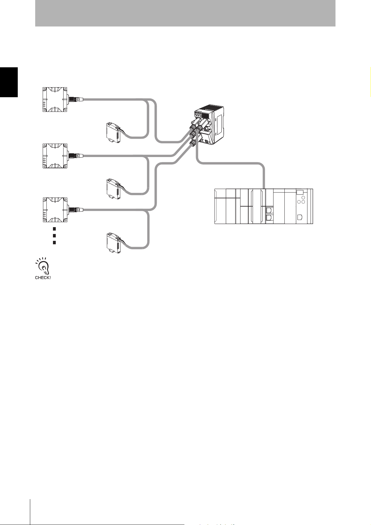
Section 1 Features
Switching Hub
PLC
Easy Addition of Reader/Writers Using an Ethernet Hub
* The DC Power Supply is needed to operate the devices.
24-VDC
power supply
24-VDC
power supply
24-VDC
power supply
Reader/Writer
Reader/Writer
Reader/Writer
Section 1
Product Overview
Simple Connection
The highly generic Ethernet is used to connect to the host device to enable easy connection with
Ethernet cable without any restrictions from the host PLC manufacturer. A Switching Hub can be used
to easily connect more than one RFID System.
Set the IP address to avoid conflicts.
18
RFID System
User's Manual
(Modbus TCP)
Page 21
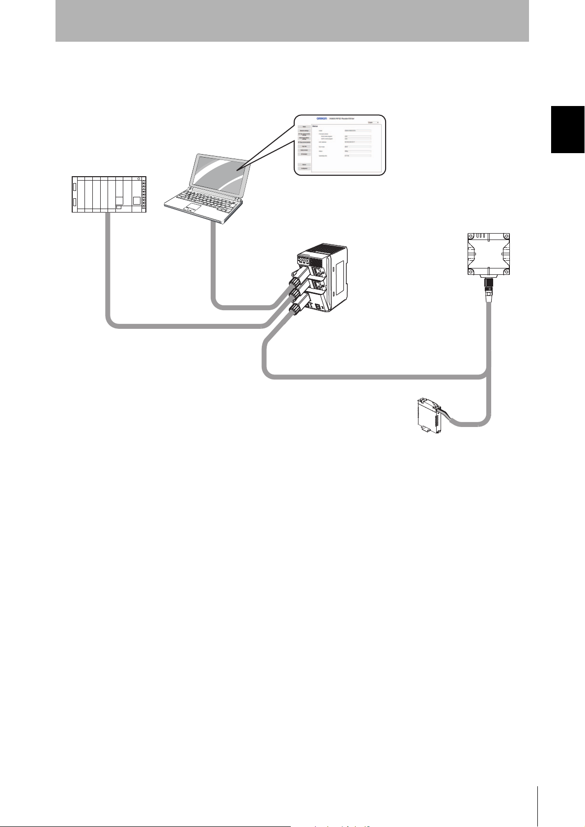
Section 1
Switching Hub
PLC
Personal computer
Reader/Writer
24-VDC
power supply
Product Overview
Easy Operation
A Web server is provided so that you can easily perform setup and status monitoring by connecting to
a computer, without the need for any special software.
Section 1 Features
You can connect a computer to the Switching Hub to easily set up the Reader/Writers and check the
status of the Reader/Writers.
RFID System
User's Manual
(Modbus TCP)
19
Page 22
Section 1
p.278
Checking the Installation Environment
Refer to Reader/Writer Installation Precautions in Section 11 Appendices to confirm the conditions under which
the RFID System will not be influenced by surrounding metal on the Reader/Writer or mutual interference
between Reader/Writers.
p.72
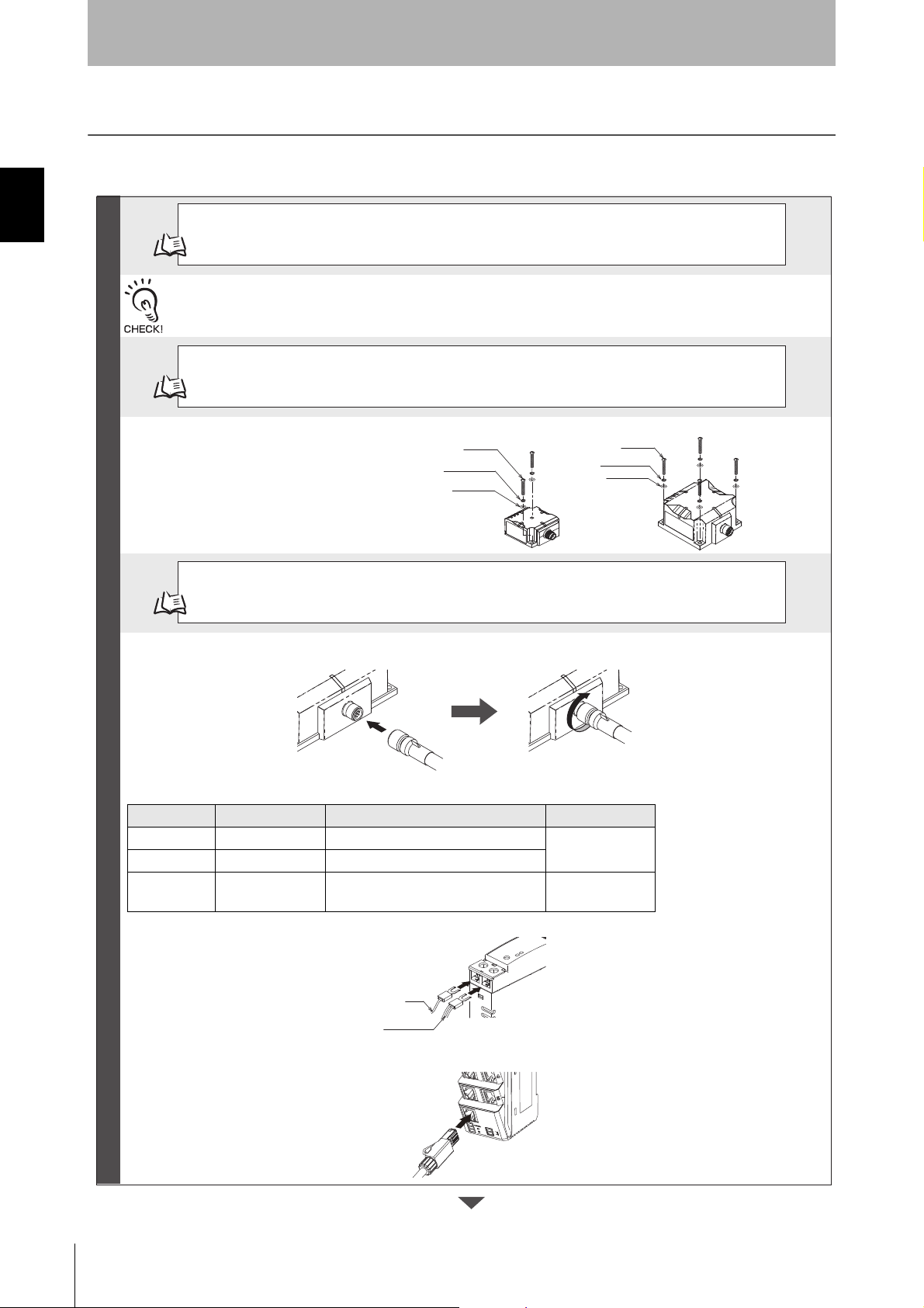
Installation
Install the Reader/Writer with four M4 screws.
V680S-HMD63-ETN: Use two screws.
V680S-HMD64-ETN/-HMD66-ETN: Use four screws.
p.87
Connections and Wiring
You must connect the power supply lines (24 VDC and 0 VDC) and the operation mode signal line in the V680SA41@M/-A51@M Cable.
Wire color Meaning Connected to Applicable wire
Brown 24 VDC +V DC output terminal
AWG20
Blue 0 VDC -V DC output terminal
Violet
Control signal Run Mode: +V DC output terminal
Safe Mode: -V DC output terminal*
AWG24
Note: If you start the Reader/Writer with the control signal connected to the -VDC side of the power supply, the Reader/Writer
will start in Safe Mode.
Insert the V680S-A41@M/-A51@M Cable into the connector on the Reader/Writer and turn the cable connector on
the Reader/Writer end clockwise to lock it in place.
Connect the RJ45 connector on the V680S-A41@M/-A51@M Cable to an Ethernet port on the host device.
* Connect the RJ45 connector to the Switching Hub when you use Switching Hub.
Preparations
Product Overview
Application Flowchart
Section 1 Application Flowchart
A simple application flowchart is described below. For correct application methods and details, refer to the
reference page or section given for each step.
M4 screw
Spring washer
Flat washer
M4 screw
Spring washer
Flat washer
Blue
Brown, Violet
RFID System
20
User's Manual
(Modbus TCP)
Page 23
Section 1
p.95
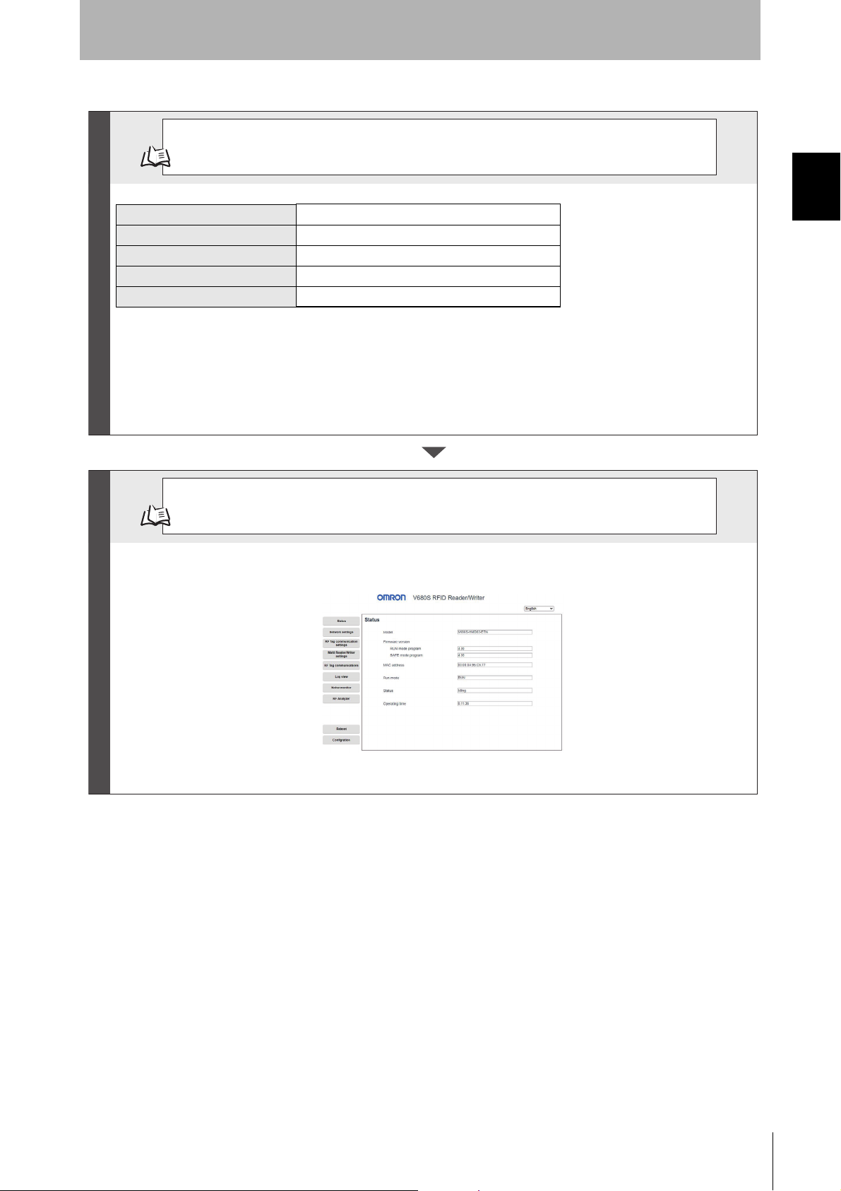
Setting Reader/Writer Communications Conditions
Change the network settings of the host device to match those of the Reader/Writer.
Host Device Setting Example
IP address: 192.168.1.100
Subnet mask: 255.255.255.0
he default network settings for the Reader/Writer are listed in the following table.
IP address 192.168.1.200
Subnet mask 255.255.255.0
Default gateway 192.168.1.254
Port number 502
Port number for Web browser 7090
Start a Web browser (e.g., Internet Explorer) on the host computer, enter http://192.168.1.200/ in the address box, and press the
Enter Key. Communications will be possible if the following view appears.
p.102
Communications Test with Host Device
Communications Preparations
Trial Operation
Product Overview
Section 1 Application Flowchart
RFID System
User's Manual
(Modbus TCP)
21
Page 24
Section 1 Application Flowchart
p.129
Using Communication Diagnostic to Check Communications Leeway
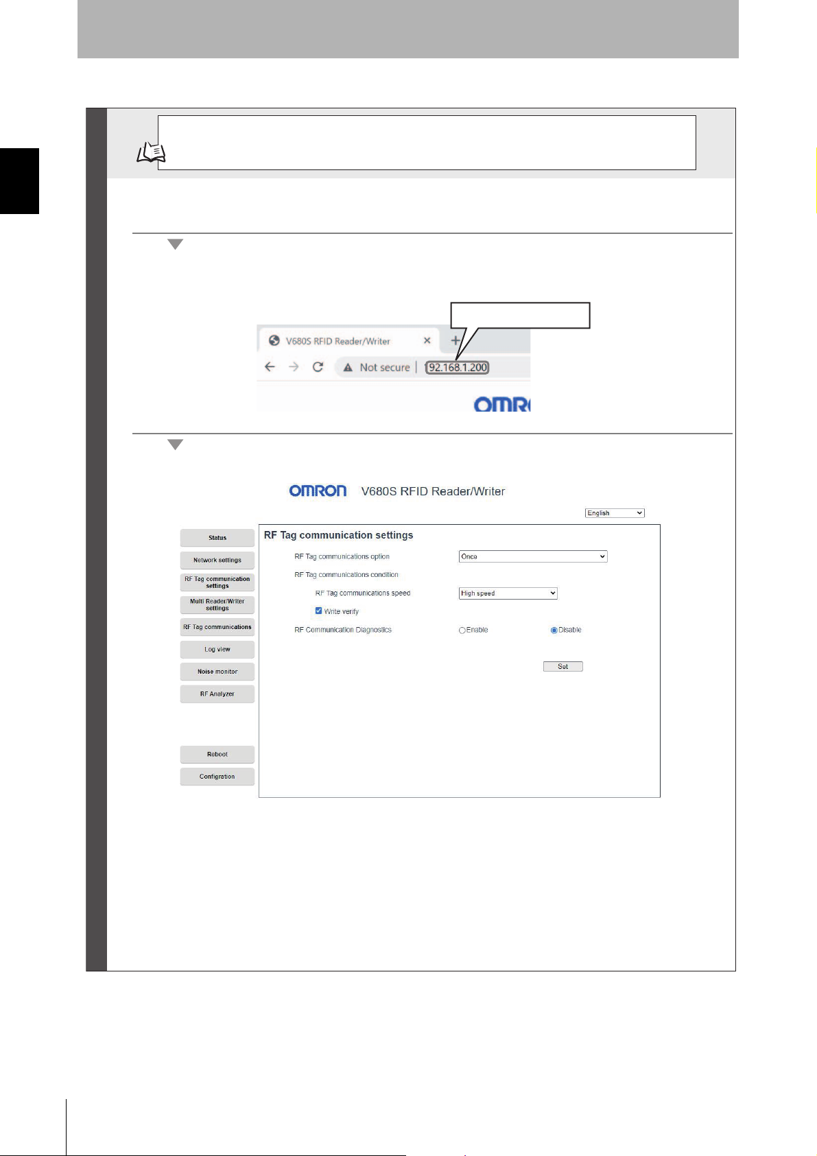
1. Connect the Ethernet cable, turn ON the power supply to the Reader/Writer, and then start a
Web browser on a computer.
2. Specify the IP address of the Reader/Writer in the address field of the Web browser.
Enter http://192.168.1.200/ if you are using the default IP address.
3. The Communications Setting View will be displayed.
Trial Operation
Section 1
Product Overview
http:// (IP address)
22
RFID System
User's Manual
(Modbus TCP)
Page 25
p.133
Using the RF Analyzer to Check the Results of Communication Diagnostic
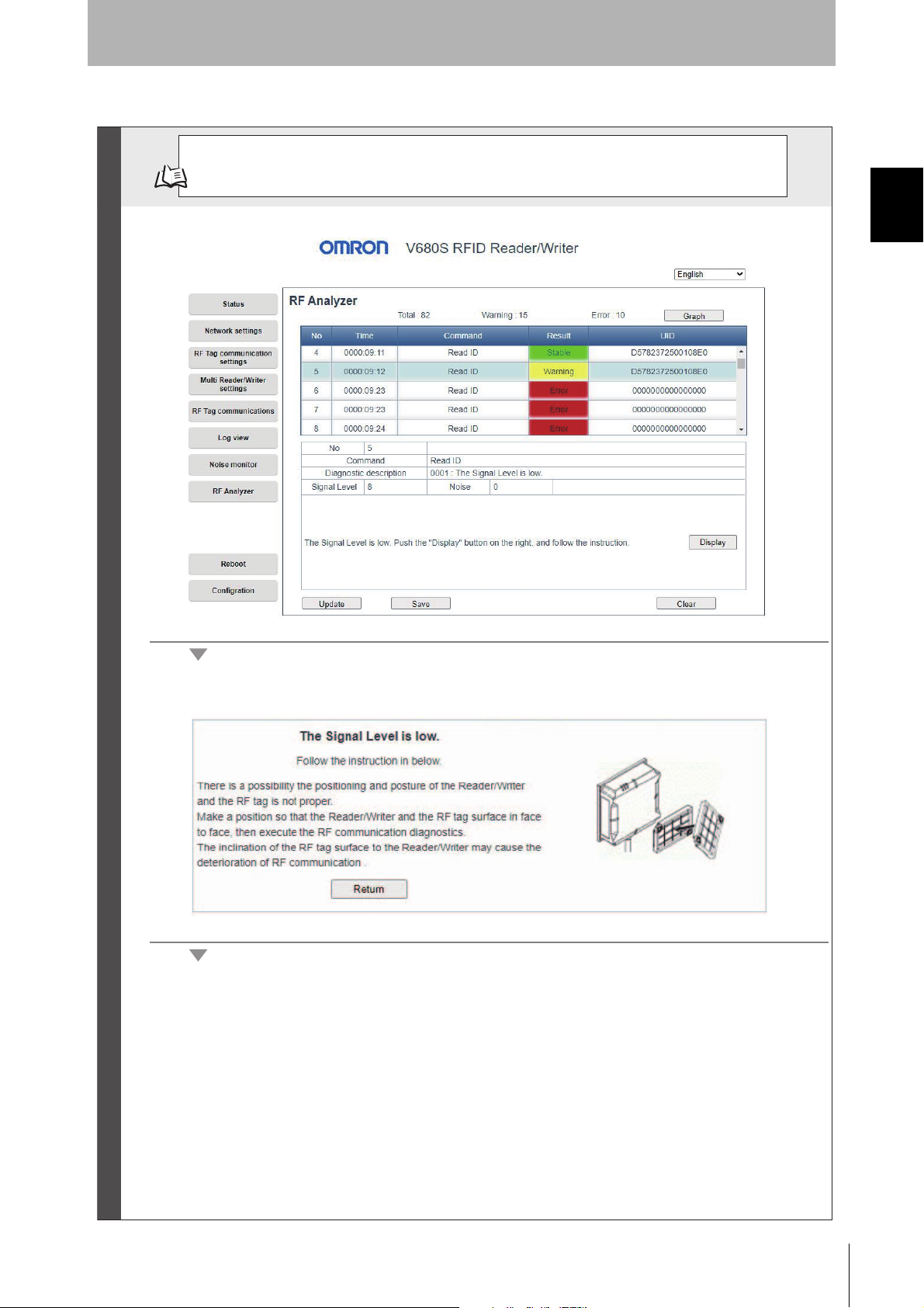
1. Display the RF Analyzer View.
2. Click the Display Button in the Details column and follow the guidance to check the assumed
causes and corrections.
Trial Operation
Section 1
Product Overview
Section 1 Application Flowchart
RFID System
User's Manual
(Modbus TCP)
23
Page 26

Section 1
3. In this example, the position of the Tag is corrected according to the guidance.
4. You can check the graph display to check quantitative information on the degree of instability.
When you are finished, perform the step to communicate with the RF Tag again and check to see if
stable communications have been achieved.
Trial Operation
Product Overview
Section 1 Application Flowchart
RFID System
24
User's Manual
(Modbus TCP)
Page 27
p.170
Communications with Actual Queries
The Reader/Writer can perform various types of communications with RF Tags.
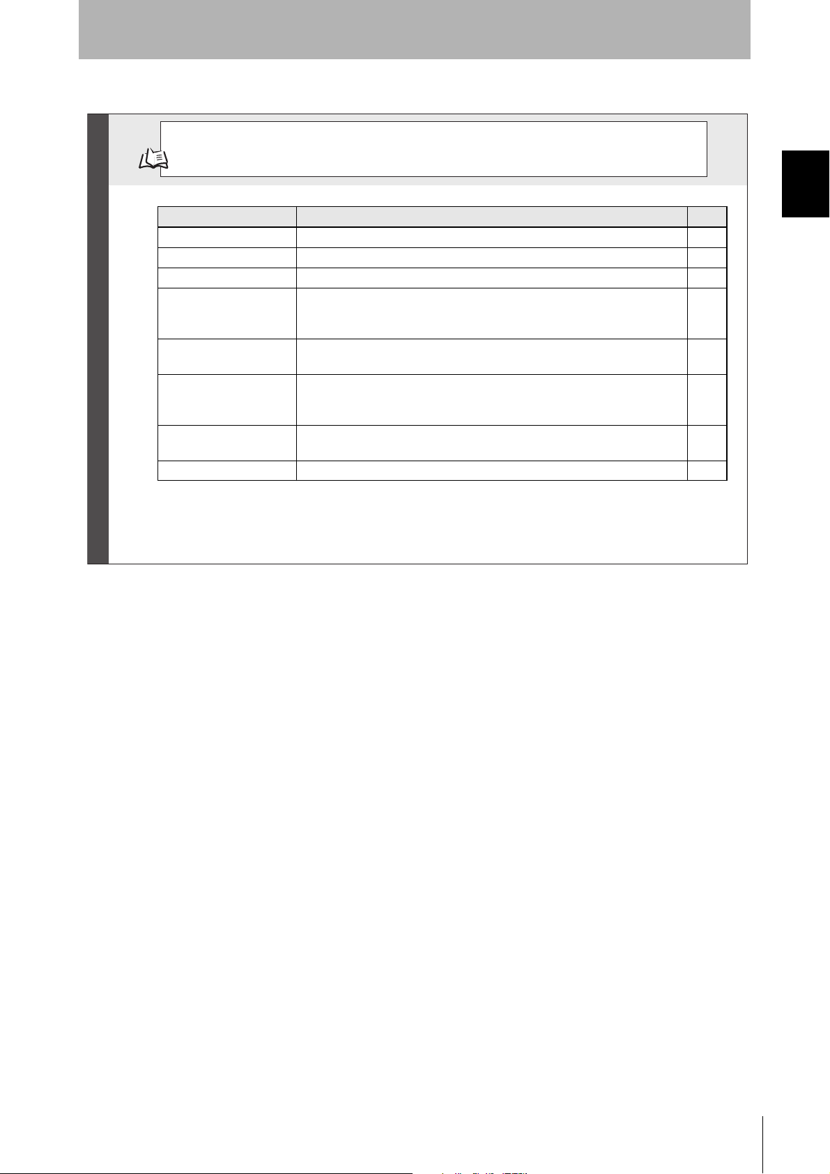
Name Description Page
READ DATA Reads data from an RF Tag in the communications field. p.170
WRITE DATA Writes data to an RF Tag in the communications field. p.171
READ ID Reads the ID code from an RF Tag in the communications field. p.172
COPY DATA Uses two Reader/Writers to copy data from the memory of an RF Tag in the
communications field of one Reader/Writer (A) to the memory of the RF Tag in
the communications field of another Reader/Writer (B).
p.173
DATA FILL Writes the specified data to the specified number of words beginning from the
specified start address. The specifications are made in the query.
p.175
LOCK This query locks the specified memory in the RF Tag.
It will no longer be possible to write data to the locked memory. The lock
cannot be released.
p.176
RF TAG OVERWRITE
COUNT CONTROL
Used to manage the number of times data is written to an RF Tag. You can
use this query for RF Tags with EEPROM memory.
p.177
RESTORE DATA This query reads the restore information from the Reader/Writer. p.178
RF Tag Communications
Section 1
Product Overview
Section 1 Application Flowchart
RFID System
User's Manual
(Modbus TCP)
25
Page 28

Section 1 Application Flowchart
p.167 Exception Code Table
p.65 Operation Indicators
p.251 Troubleshooting Flowcharts
Troubleshooting
If you Encounter a Problem...
Section 1
Product Overview
26
RFID System
User's Manual
(Modbus TCP)
Page 29
Product Specifications
Section 1
Product Overview
Reader/Writer
General Specifications
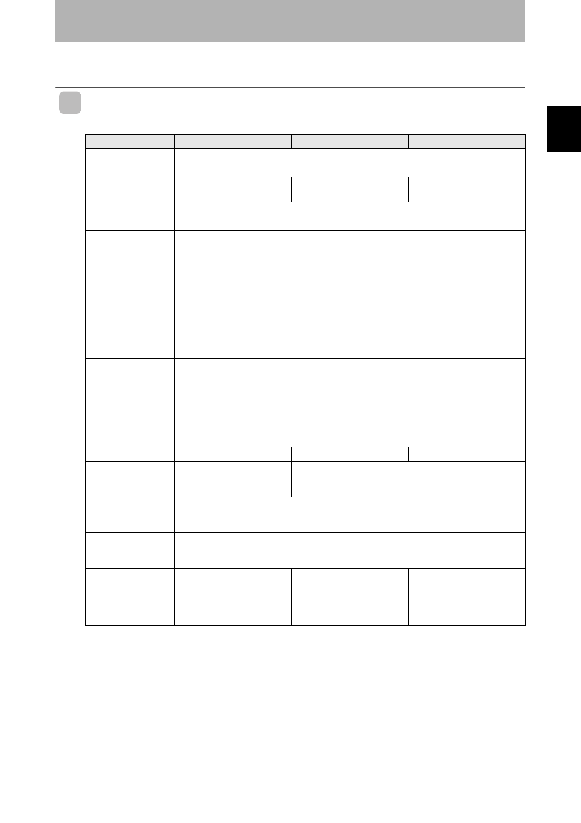
Item Model V680S-HMD63-ETN V680S-HMD64-ETN V680S-HMD66-ETN
Compliance standards ISO/IEC 18000-3 (15693)
Frequency 13.56 MHz
Dimensions 50 × 50 × 30 mm (W × H × D,
excluding protruding parts)
Power supply voltage 24 VDC (-15% to +10%)
Consumption current 0.2A max.
Ambient operating
temperature
Ambient operating
humidity
Ambient storage
temperature
Ambient storage
humidity
Insulation resistance 20 MΩ min. (at 500 VDC) between cable terminals and case
Dielectric strength 1,000 VAC, 50/60 Hz for 1 min between cable terminals and case
Vibration resistance No abnormality after application of 10 to 500 Hz, 1.5-mm double amplitude, acceleration: 100 m/s
Shock resistance No abnormality after application of 500 m/s
Degree of protection IP67 (IEC 60529:2001)
Materials Case: PBT resin, Filled resin: Urethane resin
Mass Approx. 120 g Approx. 270 g Approx. 640 g
Installation method Two M4 screws
Host device
communications
interface
Host device
communications
protocol
Accessories Instruction Sheet
Note 1. Oil resistance has been tested using a specific oil as defined in the OMRON test method.
-10 to 55°C (with no icing)
25% to 85% (with no condensation)
-25 to 70°C (with no icing)
25% to 85% (with no condensation)
10 sweeps in each of 3 axis directions (up/down, left/right, and forward/backward) for 11 minutes
each
Oil resistance equivalent to IP67F (JIS C 0920:2003, Appendix 1)
Use a screw of 12 mm or more
in length.
Ethernet 10BASE-T/100BASE-TX
Modbus TCP
Description of Regulations and
Standard
IP address label
75 × 75 × 40 mm (W × H × D,
excluding protruding parts)
2
, 3 times each in 6 directions (Total: 18 times)
Four M4 screws
Use a screw of 12mm or more in length.
Instruction Sheet
Description of Regulations and
Standard
IP address label
120 × 120 × 40 mm (W × H × D,
excluding protruding parts)
See Note 1
Instruction Sheet
Description of Regulations and
Standard
IP address label
Ferrite core
Section 1 Product Specifications
2
,
RFID System
User's Manual
(Modbus TCP)
27
Page 30
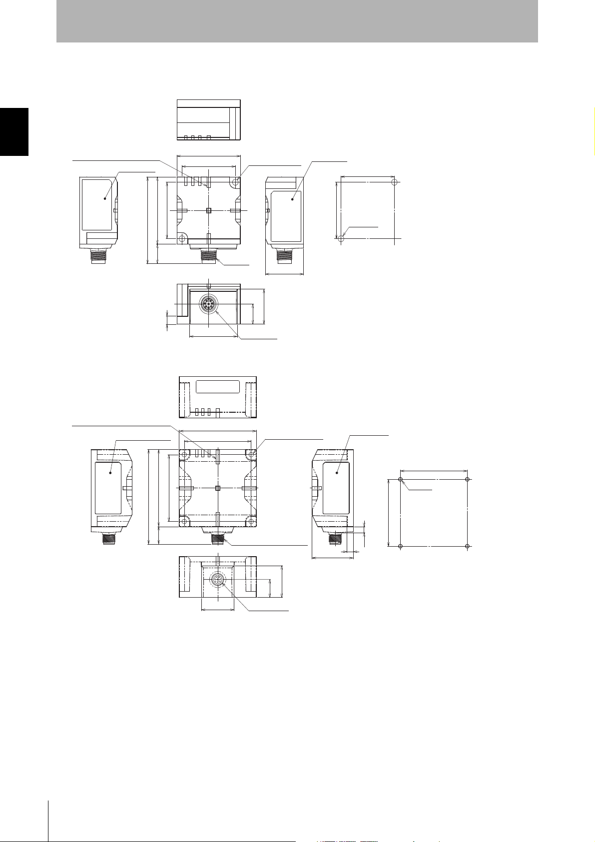
Section 1
42
50
42
50
(14.5)
Two, 4.5-dia.
mounting holes
64.5
M12×1
30
37.5
Seven, operation indicators
Standards label
Nameplate
26
15
Connector
6
Two,
M4 holes
Mount Hole Dimensions
42±0.2
42±0.2
(Unit: mm)
65
75(17)
92
65
75
32
31
17.5
5.9
6
40
Connector
Seven, Operation Indicators
Four, 4.5-dia.
mounting holes
65±0.2
65±0.2
4-M4
Mounting Hole Dimensions
Standards label
M12 threaded section
Nameplate
(Unit: mm)
Product Overview
Dimensions
V680S-HMD63-ETN
Section 1 Product Specifications
V680S-HMD64-ETN
28
RFID System
User's Manual
(Modbus TCP)
Page 31

V680S-HMD66-ETN
Mounting Hole Dimensions
110±0.2
110±0.2
Four, M4 holes
17.5
Connector
60
31
120
110
M12 threaded section
Four, 4.5-dia.
mounting holes
120
110
16
136
40
4.9
6
Operation Indicators
Standards label
Nameplate
(Unit: mm)
Section 1
Product Overview
Section 1 Product Specifications
RFID System
User's Manual
(Modbus TCP)
29
Page 32

Section 1
R7.75
17
54
5.8
23
Four, 4.5-dia.
2-R4.50
35.7
54
42
42
8.2
10
12.5
18
42±0.218±0.2
42±0.2
Mount Hole Dimensions
4-M4
Align to reader/writer
mounting screw holes
(Unit: mm)
Product Overview
Connector Cover (Standard Type)
General Specifications
Section 1 Product Specifications
Item Model V680S-A63 V680S-A64 V680S-A66
Ambient operating
temperature
Ambient operating
humidity
Ambient storage
temperature
Ambient storage
humidity
Materials POM resin
Installation method Fixing screws in four locations, with two locations fixed with reader/writer mounting screws
*1 V680S-A63/A64/A66 includes four mounting holes for fixing.
When mounting with a reader/writer already installed, or when no mounting holes for a new connector cover are available
other than the reader/writer mounting holes, the connector cover can be fixed in two locations with the same mounting holes
used for the reader/writer.
This makes it possible to install the connector cover without the need for additional mounting holes.
When tightening the products together in two locations, use the longer screw for the thicker part of the connector cover
being tightened (thickness: 11.2 mm for V680S-A63, 6 mm for 680S-A64/A66).
-10 to 55°C (with no icing)
25% to 85% (with no condensation)
-25 to 70°C (with no icing)
25% to 85% (with no condensation)
*1
Dimensions
V680S-A63
30
RFID System
User's Manual
(Modbus TCP)
Page 33

V680S-A64
(Unit: mm)
110±0.2
18±0.2
R5.75
Mounting Hole Dimensions
20
120
26
R7.75
110
10
15
33.2
Four, 4.5-dia.
9.8
18
Align to reader/writer
mounting screw holes
(Unit: mm)
Section 1
Product Overview
75
26
20
Four, 4.5-dia.
16 32.2
10
V680S-A66
65
R7.75
R5.75
9.8
Section 1 Product Specifications
Mounting Hole Dimensions
4-M4
18
18±0.2
65±0.2
Align to reader/writer
mounting screw holes
RFID System
User's Manual
(Modbus TCP)
31
Page 34

Section 1
42 ±0.2
27±0.2
28 ±0.2
42 ±0.2
4-M4
Mount Hole Dimensions
Reader/Writer
Mounting hole
Connector Cover
Mounting hole
27
Two, 4.5-dia.
10.7
35.7
23
36
(Unit: mm)
110 ±0.2
65 ±0.2
65 ±0.2
27 ±0.2
110 ±0.2
27 ±0.2
31.5 ±0.2
31.5 ±0.2
6-M4
Mounting Hole Dimensions
(V680S-HMD64-ETN)
6-M4
Connector Cover
Mounting hole
Reader/Writer
Mounting hole
Reader/Writer
Mounting hole
Mounting Hole Dimensions
(V680S-HMD66-ETN)
Connector Cover
Mounting hole
27
Two, 4.5-dia.
10.7
35.7
36
24.5
(Unit: mm)
Product Overview
Connector Cover (Slim Type)
General Specifications
Section 1 Product Specifications
Item Model V680S-A63-S V680S-A64-S
Ambient operating
temperature
Ambient operating
humidity
Ambient storage
temperature
Ambient storage
humidity
Materials PBT resin
Installation method Fixing screws in two locations
*1. In addition to the reader/writer mounting holes, two mounting holes are required for the connector cover.
-10 to 55°C (with no icing)
25% to 85% (with no condensation)
-25 to 70°C (with no icing)
25% to 85% (with no condensation)
*1
Dimensions
V680S-A63-S
V680S-A64
32
RFID System
User's Manual
(Modbus TCP)
Page 35

Section 1
14.9 dia.
L
40.7
44.7(50)
M12
14.9 dia
CONNECTOR
LABEL
CONNECTOR
VINYL INSULATED ROUND CODE 8 dia.
TYPE
V680S-A40 10M
V680S-A40 20M
V680S-A40 50M
10,000
20,000
50,000
L LENGTH
+1000
0
+2000
0
+5000
0
(Unit: mm)
14.9 dia.
L
40.7
44.7(50)
M12
14.9 dia
CONNECTOR
LABEL
CONNECTOR
ROBOT INSTRUMENTATION CABLE 8 dia.
TYPE
V680S-A50 10M
V680S-A50 20M
V680S-A50 50M
2,000
10,000
20,000
L LENGTH
+150
0
+1000
0
+2000
0
(Unit: mm)
Product Overview
Extension Cable
General Specifications
Item Model V680S-A40@M V680S-A50@M
Type Special connector--Special connector
Length 10 m 20 m 50 m 2 m 10 m 20 m
Cable diameter 8 (number of conductors: 7)
Insulation resistance 20 MΩ min. (at 500 VDC) between cable terminals and sheath
Dielectric strength 1,000 VAC, 50/60 Hz for 1 min between cable terminals and sheath
Standards UL standards
Degree of protection IP67
Maximum extension
length
Mass Approx. 0.9 kg Approx. 1.8 kg Approx. 4.4 kg Approx. 0.2 kg Approx. 1.0 kg Approx. 2.0 kg
The maximum extendable cable length using the cable and extension cable is 60 m.
Only one extension cable can be used.
60 m
Section 1 Product Specifications
V680S-A4 is a standard cable. The wire color is gray.
V680S-A5 is a robot instrumentation cable. The wire color is black.
Dimensions
V680S-A40@M
V680S-A50@M
RFID System
User's Manual
(Modbus TCP)
33
Page 36

Section 1
14.9 dia.
40.7
LABEL
(50) (40)
HEAT SHRINKABLE CABLE
54.7
HEAT SHRINKABLE CABLE
500
+60
0
CONNECTOR RJ45
(10)
500
+
6
0
0
(50)
HEAT SHRINKABLE CABLE
CONNECTOR
VINYL INSULATED ROUND CODE 8 dia.
L
TYPE
V680S-A41 2M
V680S-A41 5M
V680S-A41 10M
2,000
5,000
10,000
L LENGTH
+150
0
+300
0
+1000
0
(Unit: mm)
(Unit: mm)
Product Overview
Cables
General Specifications
Section 1 Product Specifications
Item Model V680S-A41@M V680S-A51@M V680S-A42@M
Type Special connector--RJ45 Special connector--Loose wires
Length 2 m 5 m 10 m 2 m 5 m 10 m 2 m 5 m 10 m
Cable diameter 8 (number of conductors: 7)
Insulation resistance 20 MΩ min. (at 500 VDC) between cable terminals and sheath
Dielectric strength 1,000 VAC, 50/60 Hz for 1 min between cable terminals and sheath
Standards UL standards
Degree of protection IP67
Maximum extension
60 m
length
Mass Approx.
0.2 kg
Approx.
0.5 kg
Approx.
0.9 kg
Approx.
0.2 kg
Approx.
0.6 kg
Approx.
1.0 kg
Approx.
0.2 kg
Approx.
0.5 kg
Approx.
0.9 kg
V680S-A4 is a standard cable. The wire color is gray.
V680S-A5 is a robot instrumentation cable. The wire color is black.
Dimensions
V680S-A41@M
V680S-A51@M
40.7
L
(50) (40)
HEAT SHRINKABLE CABLE
HEAT SHRINKABLE CABLE
500
+60
0
54.7
14.9 dia.
ROBOT INSTRUMENTATION CABLE 8 dia.
RFID System
34
User's Manual
(Modbus TCP)
CONNECTOR
LABEL
HEAT SHRINKABLE C
500
+
6
0
0
A
BLE
(50)
TYPE
V680S-A51 2M
V680S-A51 5M
V680S-A51 10M
CONNECTOR RJ45
(10)
L LENGTH
+150
0
2,000
+300
0
5,000
+1000
0
10,000
Page 37

V680S-A42@M
14.9 dia.
L
40.7
(50)
(50)
LABEL
(10)
(150)
(10)
CONNECTOR
VINYL INSULATED ROUND CODE 8 dia.
TYPE
V680S-A42 2M
V680S-A42 5M
V680S-A42 10M
2,000
5,000
10,000
L LENGTH
+150
0
+300
0
+1000
0
(Unit: mm)
Section 1
Product Overview
Section 1 Product Specifications
RFID System
User's Manual
(Modbus TCP)
35
Page 38

Section 1
16 dia.±0.1
20 dia.±0.1
1.1
2.7±0.1
Case material PPS resin
(Unit: mm)
Product Overview
RF Tag
V680-D1KP54T
Section 1 Product Specifications
General Specifications
Item Model V680-D1KP54T
Compliance standards ISO/IEC 18000-3 (15693)
Memory capacity 1,000 bytes (user area)
Memory type EEPROM
Data retention 10 years after writing (85°C or less), 0.5 years after writing (85 to 125°C)
Total data retention at high temperatures exceeding 125°C is 10 hours
Write endurance 100,000 writes for each block (25°C)
Ambient operating
temperature
Ambient operating
humidity
Ambient storage
temperature
Ambient storage humidity 35% to 95%
Degree of protection IP67 (IEC 60529:2001)
Vibration resistance No abnormality after application of 10 to 2,000 Hz, 1.5-mm double amplitude,
Shock resistance No abnormality after application of 500 m/s
Dimensions 20 dia. × 2.7 mm
Materials PPS resin
Weight Approx. 2 g
Metal countermeasures None
Note 1. After storing RF Tags at high temperatures, rewrite the data even if changes are not required. High temperatures are
those between 125 and 180°C.
2. Oil resistance has been tested using a specific oil as defined in the OMRON test method.
-25 to 85°C (with no icing)
35% to 95%
-40 to 125°C (with no icing)
Oil resistance equivalent to IP67G (JIS C 0920:2003, Appendix 1)
acceleration: 150 m/s
2
, 10 sweeps each in X, Y, and Z directions for 15 minutes each
2
, 3 times each in X, Y, and Z directions (Total: 18 times)
See Note 1.
See Note 2.
Dimensions
The V680-D1KP54T RF Tag can be placed in the Attachment in either direction. The direction does not affect operation.
The ID code is written in the memory of the RF Tag and may be affected by data retention characteristics at high
temperatures. Take suitable precautions when using the READ ID query for RF Tags operating at high temperatures.
You cannot use FIFO Trigger communications.
36
RFID System
User's Manual
(Modbus TCP)
Page 39

V700-A80 Attachment
22
3.5
5
8
1
40
24
18
31±0.2
22
Two, 3.5 dia. mo
unting
holes
Two, 6 dia. countersinks
Two, M3 holes
Mounting Hole Dimensions
31±0.2
Materials PPS resin
(Unit: mm)
Section 1
Product Overview
Section 1 Product Specifications
RF Tag Heat Resistance
• Storing RF Tags under high temperatures or under heat cycles will adversely affect the performance
of the internal parts and the service life of the RF Tags.
An LTPD of 10% was used for evaluation of RF Tags that reached the end of their service life after
testing under the following test conditions.
Heat cycle: 1,000 cycles of 30 minutes each between -10 and 150°C. No failures
occurred in 22 samples.
200 cycles of 30 minutes each between -10 and 180°C. No failures
occurred in 22 samples.
High-temperature storage: 1,000 hours at 150°C. No failures occurred in 22 samples.
200 hours at 180°C. No failures occurred in 22 samples.
LTPD: Lot Tolerance Percent Defective
The lower limit of the malfunction rate for lots to be considered unacceptable during reliability testing.
RFID System
User's Manual
(Modbus TCP)
37
Page 40

Section 1
V680-D1KP66MT V680-D1KP66T
Product Overview
V680-D1KP66T/-D1KP66MT
General Specifications
Section 1 Product Specifications
Item Model V680-D1KP66T V680-D1KP66MT
Compliance standards ISO/IEC 18000-3 (15693)
Memory capacity 1,000 bytes (user area)
Memory type EEPROM
Data retention 10 years after writing (85°C or less), 0.5 years after writing (85 to 125°C)
Total data retention at high temperatures exceeding 125°C is 10 hours
Write endurance 100,000 writes for each block (25°C)
Ambient operating
temperature
Ambient operating
humidity
Ambient storage
temperature
Ambient storage humidity 35% to 95%
Degree of protection IP68 (IEC 60529:2001)
Vibration resistance No abnormality after application of 10 to 2,000 Hz, 1.5-mm double amplitude, acceleration: 150 m/
Shock resistance No abnormality after application of 500 m/s
Dimensions 34 × 34 × 3.5 mm (W × H × D)
Materials PPS resin
Weight Approx. 6 g Approx. 7.5 g
Metal countermeasures None Provided
Note 1. After storing RF Tags at high temperatures, rewrite the data even if changes are not required. High temperatures are
those between 125 and 180°C.
2. Oil resistance has been tested using a specific oil as defined in the OMRON test method.
-25 to 85°C (with no icing)
35% to 95%
-40 to 125°C (with no icing)
Oil resistance equivalent to IP67G (JIS C 0920:2003, Appendix 1)
2
, 10 sweeps each in X, Y, and Z directions for 15 minutes each
s
2
, 3 times each in X, Y, and Z directions (Total: 18 times)
See Note 1.
See Note 2.
The V680-D1KP66MT must be mounted on a metallic surface. The markings on the V680-D1KP66T
and V680-D1KP66MT are shown below.
The marked surface is the communications surface. When mounting the RF Tag, face the marked surface toward the
Reader/Writer.
The ID code is written in the memory of the RF Tag and may be affected by data retention characteristics at high
temperatures. Take suitable precautions when using the READ ID query for RF Tags operating at high temperatures.
You cannot use FIFO Trigger communications.
38
RFID System
User's Manual
(Modbus TCP)
Page 41

Dimensions
25+0.2
25+0.2
25+0.2
25+0.2
3.5+0.1
Two, M3 holes
Four, 3-mm corners
Four, 4-mm corners
32
32
34
34
Two, 6 dia.
Two, 3.5 dia.
Mounting Hole Dimensions
Case material PPS resin
(Unit: mm)
25+0.2
25+0.2
25+0.2
25+0.2
Two, M3 holes
Two, 4 dia. holes
Four, 5.5-mm corners
16
4
10
3.5
3737343415
15
Case material PPS resin
(Unit: mm)
V680-D1KP66T/-D1KP66MT
V600-A86 Attachment
Section 1
Product Overview
Section 1 Product Specifications
RF Tag Heat Resistance
• Storing RF Tags under high temperatures or under heat cycles will adversely affect the performance
of the internal parts and the service life of the RF Tags.
An LTPD of 10% was used for evaluation of RF Tags that reached the end of their service life after
testing under the following test conditions.
Heat cycle: 1,000 cycles of 30 minutes each between -10 and 150°C. No failures
occurred in 22 samples.
200 cycles of 30 minutes each between -10 and 180°C. No failures
occurred in 22 samples.
High-temperature storage: 1,000 hours at 150°C. No failures occurred in 22 samples.
200 hours at 180°C. No failures occurred in 22 samples.
RFID System
User's Manual
(Modbus TCP)
LTPD: Lot Tolerance Percent Defective
The lower limit of the malfunction rate for lots to be considered unacceptable during reliability testing.
39
Page 42

Section 1
Two, 5.5 dia. mounting holes
Four, 6-mm corners
1.3
6.5 2.5 max.
Mounting Hole Dimensions
Two, M5 holes
80±0.2
80±0.2
34
95
3436.5
(Unit: mm)
Case material PFA resin
Product Overview
V680-D1KP66T-SP
General Specifications
Section 1 Product Specifications
Item Model Specification
Compliance standards ISO/IEC 18000-3 (15693)
Memory capacity 1,000 bytes
Memory type EEPROM
Data retention 10 years (85°C or less)
Write endurance 100,000 writes for each block (25°C)
Ambient operating
temperature
Ambient operating
humidity
Ambient storage
temperature
Ambient storage humidity 35% to 95% (with no condensation)
Vibration resistance 10 to 2,000 Hz, 1.5-mm double amplitude, acceleration: 150 m/s
Shock resistance No abnormality after application of 500 m/s
Dimensions 95 × 36.5 × 6.5 mm (W × H × D, excluding protruding parts)
Degree of protection IP67
Materials Exterior: PFA fluororesin
Weight Approx. 20 g
Installation method Two M5 screws
Metal countermeasures None
-25 to 70°C (with no icing)
35% to 95% (with no condensation)
-40 to 110°C (with no icing)
for 15 minutes each
RF Tag filling: PPS resin
2
, 3 times each in X, Y, and Z directions (Total: 18 times)
2
, 10 sweeps each in 3 directions
Dimensions
The marked surface is the communications surface. When mounting the RF Tag, face the marked surface toward the
Reader/Writer.
You cannot use FIFO Trigger communications.
40
RFID System
User's Manual
(Modbus TCP)
Page 43

Section 1
(60 dia.)
80 dia.
14 dia.
10±0.2
7.51.25
(1.25)
(5°)
(5°)
18 dia.
Two, 1-mm corners
(Unit: mm)
Case material PPS resin
Product Overview
V680-D1KP58HTN
General Specifications
Item Model V680-D1KP58HTN
Compliance standards ISO/IEC 18000-3 (15693)
Memory capacity 1,000 bytes (user area)
Memory type EEPROM
Data retention 10 years after writing (85°C or less), 0.5 years after writing (85 to 125°C)
Total data retention at high temperatures exceeding 125°C is 10 hours
Write endurance 100,000 writes for each block (25°C)
Ambient operating
temperature
Ambient operating
humidity
Ambient storage
temperature
Ambient storage
humidity
Degree of protection IP67 (IEC 60529:2001)
Vibration resistance No abnormality after application of 10 to 2,000 Hz, 1.5-mm double amplitude, acceleration: 150 m/s2,
Shock resistance No abnormality after application of 500 m/s
Dimensions 80 dia. × 10 mm
Materials PPS resin
Weight Approx. 70 g
Note1. After storing RF Tags at high temperatures, rewrite the data even if changes are not required. High temperatures are
those between 125 and 250°C.
2. Oil resistance has been tested using a specific oil as defined in the OMRON test method.
-25 to 85°C (with no icing)
No restrictions.
-40 to 250°C (with no icing)
(Data retention: -40 to 125°C)
No restrictions.
Oil resistance equivalent to IP67G (JIS C 0920:2003, Appendix 1)
10 sweeps each in X, Y, and Z directions for 15 minutes each
2
, 3 times each in X, Y, and Z directions (Total: 18 times)
See Note 1
See Note 2
Section 1 Product Specifications
Dimensions
V680-D1KP58HTN
The RF Tag can be placed in the Attachment in either direction. The direction does not affect operation.
RFID System
User's Manual
(Modbus TCP)
41
Page 44

Section 1
Mounting Hole Dimensions
20 dia.
M12
M12
4050
11.5
15
110
3.2 dia.
12 dia.
17
1 split pin (nominal dimensions: 3.2-mm dia. × 20-mm length)
Accessories: 2 nuts (M12)
(Unit: mm)
Product Overview
V680-A80 Attachment
This Attachment is used to hold V680-D1KP58HTN ID Tags.
Applicable model: V680-D1KP58HTN
Section 1 Product Specifications
High-temperature Applications (V680-D1KP58HTN)
Data Retention
•Due to the characteristics of EEPROM, any data that is written to an RF Tag may be lost if it is used
in a high-temperature environment that exceeds 125°C for a total of more than 10 hours. Always
reset the data holding time before a total of 10 hours is reached.
•Communications between the Reader/Writer and RF Tags may fail in high-temperature environments
of 85°C or higher. Do not perform communications between the Reader/Writer and RF Tag in a high-
temperature environment of 85°C or higher.
•Due to the characteristics of EEPROM, the UID (RF Tag ID code) may be lost if an RF Tag is used in
a high-temperature environment that exceeds 125°C. Do not use commands that use the UID in
high-temperature environments that exceed 125°C.
•Do not use the ID READ command.
•You cannot use FIFO trigger communications.
42
Total Usage Time
This section gives the total time that an RF Tag can be placed at high temperatures.
Total usage time: 9 hours
Total usage time: 6 hours
Total usage time: 4 hours
Total usage time: 1 hour
1 hour at high
temperature*1
1 hour at
°C
25
Data retention
time reset.
2 hours at
°C
25
The time that the RF Tag is left at temperatures lower than
the high temperatures are not included in the total usage time.
Fig. Conceptual Diagram of Resetting the Data Retention Time
*1 High temperatures are those between 125 and 250°C.
RFID System
User's Manual
(Modbus TCP)
3 hours at high
temperature*1
3 hours at
°C
25
2 hours at high
temperature*1
2 hours at
°C
25
Data written to the memory
of the RF Tag.
Total usage time: 2 hours
3 hours at high
temperature*1
1 hour at
°C
25
Data retention
time reset.
2 hours at high
temperature*1
3 hours at
°C
25
Page 45

Section 1
Product Overview
Data Retention Time Reset Procedure
Always use the following procedure to reset the data holding time before a total of 10 hours is reached.
When Using RF Tag Memory Addresses 0010 to 0015 hex
1. Read the data from RF Tag addresses 0010 to 0015 hex.
2. Write the read data to RF Tag memory addresses 0010 to 0015
hex.
The data retention time is reset only for the RF Tag memory addresses that are written.
To reset the data retention time, write the same data to all of the memory addresses that are used in the RF Tag.
RF Tag Memory
hex
hex
hex
hex
hex
hex
00
11
22
33
44
55
hex
hex
hex
hex
hex
hex
0010
0011
0012
0013
0014
0015
Write the data to the RF Tag
memory addresses that were read.
Read the memory addresses
that are used in the RF Tag.
RF Tag Memory
hex
0010
0011
0012
0013
0014
0015
hex
hex
hex
hex
hex
00
11
22
33
44
55
Section 1 Product Specifications
hex
hex
hex
hex
hex
hex
Heat Resistance
Storing RF Tags under high temperatures or under heat cycles will adversely affect the performance of
the internal parts and the service life of the RF Tags.
The RF Tag were placed in the following high temperatures and then evaluated in-house. It was
confirmed that no problems occurred.
1) 2,000 cycles of 30 minutes each between room temperature and 200°C
2) 500 hours at 250°C
RFID System
User's Manual
(Modbus TCP)
43
Page 46

Section 1
V680S-D2KF67M/-D8KF67M V680S-D2KF67/-D8KF67
Product Overview
V680S-D2KF67/-D2KF67M/-D8KF67/-D8KF67M
General Specifications
Section 1 Product Specifications
Item Model V680S-D2KF67 V680S-D2KF67M V680S-D8KF67 V680S-D8KF67M
Compliance standards ISO/IEC 18000-3 (15693)
Memory capacity 2,000 bytes (user area) 8,192 bytes (user area)
Memory type FRAM
Data retention 10 years after writing (85°C or less)
Write Endurance One trillion times per block (85°C or less), Access frequency
Ambient operating
temperature
Ambient operating
humidity
Ambient storage
temperature
Ambient storage humidity 35% to 85%
Degree of protection IP68 (IEC 60529:2001), Oil resistance equivalent to IP67G (JIS C 0920:2003, Appendix 1)
Vibration resistance No abnormality after application of 10 to 2,000 Hz, 1.5-mm double amplitude, acceleration: 150 m/
Shock resistance No abnormality after application of 500 m/s
Dimensions 40 × 40 × 5 mm (W × H × D)
Materials PPS resin
Weight Approx. 11.5 g Approx. 12 g Approx. 11.5 g Approx. 12 g
Metal countermeasures None Provided None Provided
Note 1. The number of accesses is the total number of reads and writes.
2. Oil resistance has been tested using a specific oil as defined in the OMRON test method.
-20 to 85°C (with no icing)
35% to 85%
-40 to 125°C (with no icing)
IPX9K (DIN 40 050)
2
s
, 10 sweeps each in X, Y, and Z directions for 15 minutes each
2
, 3 times each in X, Y, and Z directions (Total: 18 times)
See Note 1.
: One trillion times
See Note 2.
The V680S-D2KF67M/-D8KF67M must be mounted on a metallic surface. The markings on the V680-
D2KF67/-D8KF67 and V680-D2KF67M/-D8KF67M are shown below.
The marked surface is the communications surface. When mounting the RF Tag, face the marked surface toward the
Reader/Writer.
You can use the V680S-D8KF67@ with Reader/Writers with firmware version 2.00 or higher.
44
RFID System
User's Manual
(Modbus TCP)
Page 47

Dimensions
(Unit: mm)
Two, 3.5-dia.
mounting holes
32±0.2
40
32±0.2
40
32±0.2
32±0.2
2-M3
2
5
Mounting Hole Dimensions
Mounting height 5
+1
0
Case material PPS resin
V680S-D2KF67/-D2KF67M/-D8KF67/-D8KF67M
Section 1
Product Overview
Section 1 Product Specifications
RFID System
User's Manual
(Modbus TCP)
45
Page 48

Section 1
Product Overview
V680S-D2KF68/-D2KF68M/-D8KF68/-D8KF68M
General Specifications
Section 1 Product Specifications
Item Model V680S-D2KF68 V680S-D2KF68M V680S-D8KF68 V680S-D8KF68M
Compliance standards ISO/IEC 18000-3 (15693)
Memory capacity 2,000 bytes (user area) 8,192 bytes (user area)
Memory type FRAM
Data retention 10 years after writing (85°C or less)
Write Endurance One trillion times per block (85°C or less), Access frequency
Ambient operating
temperature
Ambient operating humidity 35% to 85%
Ambient storage temperature -40 to 125°C (with no icing)
Ambient storage humidity 35% to 85%
Degree of protection IP68 (IEC 60529), Oil resistance equivalent to IP67G (JIS C 0920:2003, Appendix 1)
Vibration resistance No abnormality after application of 10 to 500 Hz, 1.5-mm double amplitude, acceleration: 100
Shock resistance No abnormality after application of 500 m/s
Dimensions 86 × 54 × 10 mm (W × H × D)
Materials PPS resin
Weight Approx. 44 g Approx. 46 g Approx. 44 g Approx. 46 g
Metal countermeasures None Provided None Provided
Note 1. The number of accesses is the total number of reads and writes.
2. Oil resistance has been tested using a specific oil as defined in the OMRON test method.
-20 to 85°C (with no icing)
IPX9K (DIN 40 050)
2
, 10 sweeps each in X, Y, and Z directions for 11 minutes each
m/s
2
, 3 times each in X, Y, and Z directions (Total: 18
times)
See Note 1.
: One trillion times
See Note 2.
The V680S-D2KF68M/-D8KF68M must be mounted on a metallic surface. The markings on the V680-
D2KF68/-D8KF68 and V680-D2KF68M/-D8KF68M are shown below.
V680S-D2KF68M/-D8KF68M V680S-D2KF68/-D8KF68
The marked surface is the communications surface. When mounting the RF Tag, face the marked surface toward the
Reader/Writer.
46
RFID System
User's Manual
(Modbus TCP)
You can use the V680S-D8KF68@ with Reader/Writers with firmware version 2.00 or higher.
Page 49

Dimensions
2-M4
76±0.2
86
44±0.2
54
Two, 4.5-dia.
mounting holes
(Unit: mm)
5
Mounting Hole Dimensions
76±0.2
44±0.2
Mounting height 10
10
+1
0
Case material PPS resin
V680S-D2KF68/-D2KF68M/-D8KF68/-D8KF68M
Section 1
Product Overview
Section 1 Product Specifications
RFID System
User's Manual
(Modbus TCP)
47
Page 50

Section 1
Product Overview
Data Characteristics
Section 1 Data Characteristics
Communications Range Specifications
V680S-HMD63-ETN
Reader/Writer RF Tag Communications distance specification
V680S-HMD63ETN (mounted to
metallic material)
V680-D1KP54T (mounted to non-metallic material) Read 0.0 to 24.0 mm (axis offset: ±10 mm)
Write 0.0 to 20.0 mm (axis offset: ±10 mm)
V680-D1KP66T (mounted to non-metallic material) Read 0.0 to 30.0 mm (axis offset: ±10 mm)
Write 0.0 to 25.0 mm (axis offset: ±10 mm)
V680-D1KP66MT (mounted to metallic material) Read 0.0 to 25.0 mm (axis offset: ±10 mm)
Write 0.0 to 20.0 mm (axis offset: ±10 mm)
V680-D1KP66T-SP (mounted to non-metallic material) Read 0.0 to 25.0 mm (axis offset: ±10 mm)
Write 0.0 to 20.0 mm (axis offset: ±10 mm)
V680S-D2KF67 (mounted to non-metallic material) Read 7.0 to 40.0 mm (axis offset: ±10 mm)
Write 7.0 to 40.0 mm (axis offset: ±10 mm)
V680S-D2KF67M (mounted to metallic material) Read 6.0 to 30.0 mm (axis offset: ±10 mm)
Write 6.0 to 30.0 mm (axis offset: ±10 mm)
V680S-D8KF67 (mounted to non-metallic material) Read 7.0 to 40.0 mm (axis offset: ±10 mm)
Write 7.0 to 40.0 mm (axis offset: ±10 mm)
V680S-D8KF67M (mounted to metallic material) Read 6.0 to 30.0 mm (axis offset: ±10 mm)
Write 6.0 to 30.0 mm (axis offset: ±10 mm)
48
RFID System
User's Manual
(Modbus TCP)
Page 51

Installation Conditions
Communications range
V680-D1KP54T
V680S-HMD63-ETN
Non-metallic material
(Examples: Resin, plastic, wood, etc.)
Non-metallic material
(Examples: Resin, plastic, wood, etc.)
Metallic material
Communications range
V680-D1KP66T
V680S-HMD63-ETN
Non-metallic material
(Examples: Resin, plastic, wood, etc.)
Non-metallic material
(Examples: Resin, plastic, wood, etc.)
Metallic material
Communications range
V680-D1KP66MT
V680S-HMD63-ETN
Non-metallic material
(Examples: Resin, plastic, wood, etc.)
Metallic material
Communications range
V680-D1KP66T-SP
V680S-HMD63-ETN
Non-metallic material
(Examples: Resin, plastic, wood, etc.)
Metallic material
Non-metallic material
(Examples: Resin, plastic, wood, etc.)
V680-D1KP54T V680-D1KP66T
V680-D1KP66MT V680-D1KP66T-SP
Metallic material
Non-metallic material
(Examples: Resin, plastic, wood, etc.)
Communications range
V680S-D2KF67/-D8KF67
V680S-HMD63-ETN
Non-metallic material
(Examples: Resin, plastic, wood, etc.)
Metallic material
Non-metallic material
(Examples: Resin, plastic, wood, etc.)
Communications range
V680S-D2KF67M/-D8KF67M
V680S-HMD63-ETN
Non-metallic material
(Examples: Resin, plastic, wood, etc.)
Metallic material
V680S-D2KF67/-D8KF67 V680S-D2KF67M/-D8KF67M
Metallic material
Section 1
Product Overview
Section 1 Data Characteristics
RFID System
User's Manual
(Modbus TCP)
49
Page 52

Section 1
Product Overview
V680S-HMD64-ETN
Section 1 Data Characteristics
V680S-HMD64-ETN
(mounted to metallic material)
Reader/Writer RF Tag Communications Range Specification
V680-D1KP54T
(mounted to non-metallic material)
V680-D1KP66T
(mounted to non-metallic material)
V680-D1KP66MT
(mounted to metallic material)
V680-D1KP66T-SP
(mounted to non-metallic material)
V680-D1KP58HTN Read 7.5 to 75.0 mm (axis offset: ±10 mm)
V680S-D2KF67
(mounted to non-metallic material)
V680S-D2KF67M
(mounted to metallic material)
V680S-D8KF67
(mounted to non-metallic material)
V680S-D8KF67M
(mounted to metallic material)
V680S-D2KF68
(mounted to non-metallic material)
V680S-D2KF68M
(mounted to metallic material)
V680S-D8KF68
(mounted to non-metallic material)
V680S-D8KF68M
(mounted to metallic material)
Read 0.0 to 33.0 mm (axis offset: ±10 mm)
Write 0.0 to 28.0 mm (axis offset: ±10 mm)
Read 0.0 to 47.0 mm (axis offset: ±10 mm)
Write 0.0 to 42.0 mm (axis offset: ±10 mm)
Read 0.0 to 35.0 mm (axis offset: ±10 mm)
Write 0.0 to 30.0 mm (axis offset: ±10 mm)
Read 0.0 to 42.0 mm (axis offset: ±10 mm)
Write 0.0 to 37.0 mm (axis offset: ±10 mm)
Write 7.5 to 75.0 mm (axis offset: ±10 mm)
Read 5.0 to 65.0 mm (axis offset: ±10 mm)
Write 5.0 to 65.0 mm (axis offset: ±10 mm)
Read 3.0 to 40.0 mm (axis offset: ±10 mm)
Write 3.0 to 40.0 mm (axis offset: ±10 mm)
Read 5.0 to 65.0 mm (axis offset: ±10 mm)
Write 5.0 to 65.0 mm (axis offset: ±10 mm)
Read 3.0 to 40.0 mm (axis offset: ±10 mm)
Write 3.0 to 40.0 mm (axis offset: ±10 mm)
Read 7.5 to 75.0 mm (axis offset: ±10 mm)
Write 7.5 to 75.0 mm (axis offset: ±10 mm)
Read 5.5 to 55.0 mm (axis offset: ±10 mm)
Write 5.5 to 55.0 mm (axis offset: ±10 mm)
Read 7.5 to 75.0 mm (axis offset: ±10 mm)
Write 7.5 to 75.0 mm (axis offset: ±10 mm)
Read 5.5 to 55.0 mm (axis offset: ±10 mm)
Write 5.5 to 55.0 mm (axis offset: ±10 mm)
You can use the V680S-D8KF6@ with Reader/Writers with firmware version 2.00 or higher.
50
RFID System
User's Manual
(Modbus TCP)
Page 53

Installation Conditions
Communications
range
V680S-D2KF67/-D8KF67
V680S-HMD64-ETN
Non-metallic material
(Examples: Resin, plastic, wood, etc.)
Metallic material
Non-metallic material
(Examples: Resin, plastic, wood, etc.)
Communications
range
V680S-D2KF67M/-D8KF67M
V680S-HMD64-ETN
Non-metallic material
(Examples: Resin, plastic, wood, etc.)
Metallic material
Communications
range
V680S-D2KF68/-D8KF68
V680S-HMD64-ETN
Non-metallic material
(Examples: Resin, plastic, wood, etc.)
Metallic material
Non-metallic material
(Examples: Resin, plastic, wood, etc.)
Metallic material
Communications
range
V680S-D2KF68M/-D8KF68M
V680S-HMD64-ETN
Non-metallic material
(Examples: Resin, plastic, wood, etc.)
Metallic material
Metallic material
V680S-D2KF67/-D8KF67 V680S-D2KF67/-D8KF67M
V680S-D2KF68/-D8KF68 V680S-D2KF68/-D8KF68M
Section 1
Product Overview
Section 1 Data Characteristics
RFID System
User's Manual
(Modbus TCP)
51
Page 54

Section 1
Communications
range
V680-D1KP54T
V680S-HMD64-ETN
Non-metallic material
(Examples: Resin, plastic, wood, etc.)
Metallic material
Non-metallic material
(Examples: Resin, plastic, wood, etc.)
Communications
range
V680-D1KP66T
V680S-HMD64-ETN
Non-metallic material
(Examples: Resin, plastic, wood, etc.)
Non-metallic material
(Examples: Resin, plastic, wood, etc.)
Metallic material
Communications
range
V680-D1KP66MT
V680S-HMD64-ETN
Non-metallic material
(Examples: Resin, plastic, wood, etc.)
Metallic material
Communications
range
V680-D1KP66T-SP
V680S-HMD64-ETN
Non-metallic material
(Examples: Resin, plastic, wood, etc.)
Metallic material
Non-metallic material
(Examples: Resin, plastic, wood, etc.)
Communications
range
V680-D1KP58HTN
V680S-HMD64-ETN
Non-metallic material
(Examples: Resin, plastic, wood, etc.)
Metallic material
Non-metallic material
(Examples: Resin, plastic, wood, etc.)
V680-A40 Attachment
V680-D1KP54T V680-D1KP66T
V680-D1KP66M V680-D1KP66T-SP
V680-D1KP58HTN
Metallic material
Non-metallic material
(Examples: Resin, plastic, wood, etc.)
Product Overview
Section 1 Data Characteristics
52
RFID System
User's Manual
(Modbus TCP)
Page 55

V680S-HMD66-ETN
Reader/Writer RF Tag Communications Range Specification
V680S-HMD66-ETN
(mounted to metallic material)
Section 1
Product Overview
V680-D1KP54T
(mounted to non-metallic material)
V680-D1KP66T
(mounted to non-metallic material)
V680-D1KP66MT
(mounted to metallic material)
V680-D1KP66T-SP
(mounted to non-metallic material)
V680-D1KP58HTN Read 10.0 to 90.0 mm (axis offset: ±10 mm)
V680S-D2KF67
(mounted to non-metallic material)
V680S-D2KF67M
(mounted to metallic material)
V680S-D8KF67
(mounted to non-metallic material)
V680S-D8KF67M
(mounted to metallic material)
V680S-D2KF68
(mounted to non-metallic material)
V680S-D2KF68M
(mounted to metallic material)
V680S-D8KF68
(mounted to non-metallic material)
V680S-D8KF68M
(mounted to metallic material)
Read 7.5 to 75.0 mm (axis offset: ±10 mm)
Write 7.5 to 75.0 mm (axis offset: ±10 mm)
Read 0.0 to 45.0 mm (axis offset: ±10 mm)
Write 0.0 to 38.0 mm (axis offset: ±10 mm)
Read 0.0 to 37.0 mm (axis offset: ±10 mm)
Write 0.0 to 30.0 mm (axis offset: ±10 mm)
Read 0.0 to 59.0 mm (axis offset: ±10 mm)
Write 0.0 to 52.0 mm (axis offset: ±10 mm)
Write 10.0 to 800.0 mm (axis offset: ±10 mm)
Read 7.0 to 70.0 mm (axis offset: ±10 mm)
Write 7.0 to 70.0 mm (axis offset: ±10 mm)
Read 4.0 to 45.0 mm (axis offset: ±10 mm)
Write 4.0 to 45.0 mm (axis offset: ±10 mm)
Read 7.0 to 70.0 mm (axis offset: ±10 mm)
Write 7.0 to 70.0 mm (axis offset: ±10 mm)
Read 4.0 to 45.0 mm (axis offset: ±10 mm)
Write 4.0 to 45.0 mm (axis offset: ±10 mm)
Read 10.0 to 100.0 mm (axis offset: ±10 mm)
Write 10.0 to 100.0 mm (axis offset: ±10 mm)
Read 7.5 to 75.0 mm (axis offset: ±10 mm)
Write 7.5 to 75.0 mm (axis offset: ±10 mm)
Read 10.0 to 100.0 mm (axis offset: ±10 mm)
Write 10.0 to 100.0 mm (axis offset: ±10 mm)
Read 7.5 to 75.0 mm (axis offset: ±
Write 7.5 to 75.0 mm (axis offset: ±10 mm)
10 mm)
Section 1 Data Characteristics
You can use the V680S-D8KF6@ with Reader/Writers with firmware version 2.00 or higher.
RFID System
User's Manual
(Modbus TCP)
53
Page 56

Section 1
Communications
range
Non-metallic material
(Examples: Resin, plastic, wood, etc.)
Non-metallic material
(Examples: Resin, plastic, wood, etc.)
Communications
range
Non-metallic material
(Examples: Resin, plastic, wood, etc.)
V680S-HMD66-ETN
Metallic material V680S-HMD66-ETNMetallic material
Metallic material
V680S-D2KF67M/-D8KF67M
V680S-D2KF67/-D8KF67
Communications
range
V680S-D2KF68/-D8KF68
Non-metallic material
(Examples: Resin, plastic, wood, etc.)
Non-metallic material
(Examples: Resin, plastic, wood, etc.)
V680S-HMD66-ETN
Metallic material
Communications
range
V680S-D2KF68M/-D8KF68M
Non-metallic material
(Examples: Resin, plastic, wood, etc.)
Metallic material
V680S-HMD66-ETN
Metallic material
V680S-D2KF67/-D8KF67 V680S-D2KF67M/-D8KF67M
V680S-D2KF68/-D8KF68 V680S-D2KF68M/-D8KF68M
Product Overview
Installation Conditions
Section 1 Data Characteristics
54
RFID System
User's Manual
(Modbus TCP)
Page 57

Section 1
Communications
range
V680-D1KP54T
V680S-HMD66-ETN
Non-metallic material
(Examples: Resin, plastic, wood, etc.)
Non-metallic material
(Examples: Resin, plastic, wood, etc.)
Communications
range
V680-D1KP66T
Non-metallic material
(Examples: Resin, plastic, wood, etc.)
Non-metallic material
(Examples: Resin, plastic, wood, etc.)
Communications
range
Non-metallic material
(Examples: Resin, plastic, wood, etc.)
Communications
range
V680-D1KP66T-SP
Non-metallic material
(Examples: Resin, plastic, wood, etc.)
Non-metallic material
(Examples: Resin, plastic, wood, etc.)
Communications
range
V680-D1KP58HTN
Non-metallic material
(Examples: Resin, plastic, wood, etc.)
Non-metallic material
(Examples: Resin, plastic, wood, etc.)
V680-A40 Attachment
Metallic material V680S-HMD66-ETNMetallic material
V680S-HMD66-ETNMetallic material V680S-HMD66-ETNMetallic material
V680S-HMD66-ETNMetallic material
V680-D1KP54T V680-D1KP66T
V680-D1KP66MT V680-D1KP66T-SP
V680-D1KP58HTN
V680-D1KP66MT
Metallic material
Non-metallic material
(Examples: Resin, plastic, wood, etc.)
Product Overview
Section 1 Data Characteristics
RFID System
User's Manual
(Modbus TCP)
55
Page 58

Section 1
Product Overview
MEMO
Section 1 Data Characteristics
56
RFID System
User's Manual
(Modbus TCP)
Page 59

Section 2 System Configuration
System Configuration 58
Section 2 System Configuration
RFID System
User's Manual
(Modbus TCP)
57
Page 60

Section 2 System Configuration
Reader/Writer
(V680S-HMD6 -ETN)
Host device (e.g., PLC)
RF Tag
(V680 Series and V680S Series)
24-VDC power supply
Cable (V680S-A40 M/-A41 M/-A42 M/-A50 M/-A51 M)
Section 2
System Configuration
System Configuration
One Reader/Writer is connected to the Host device (e.g., PLC)
Use a device supporting STP cables for the host device (such as a Switching Hub or PLC) which is connected the specified
Cables (V680S-A41 @M/-A42 @M/-A51 @M). Ground the host device to a ground resistance of 100 Ω or less.
Use one of the specified Cables (V680S-A40 @M/-A41 @M/-A42 @M/-A50 @M/-A51 @M)). Maximum extension length of the
cable is 60m.
It is not possible to connect the extension cable and extension cable (V680S-A40 @M/-A50 @M).
58
RFID System
User's Manual
(Modbus TCP)
Page 61

Section 2
Ethernet cable
24-VDC
power supply
RF Tag
(V680 Series and V680S Series)
RF Tag
(V680 Series and V680S Series)
Host device (e.g., PLC)
24-VDC
power supply
Reader/Writer
(V680S-HMD6 -ETN)
Reader/Writer
(V680S-HMD6 -ETN)
Cable (V680S-A40 M/-A41 M/-A42 M/-A50 M/-A51 M)
Cable (V680S-A40 M/-A41 M/-A42 M/-A50 M/-A51 M)
System Configuration
The plural Reader/Writer’s are connected to the Host device (e.g., PLC)
Section 2 System Configuration
Use a device supporting STP cables for the host device (such as a Switching Hub or PLC) which is connected the specified
Cables (V680S-A41 @M/-A42 @M/-A51 @M). Ground the host device to a ground resistance of 100 Ω or less.
Use one of the specified Cables (V680S-A40 @M/-A41 @M/-A42 @M/-A50 @M/-A51 @M)). Maximum extension length of the
cable is 60m.
It is not possible to connect the extension cable and extension cable (V680S-A40 @M/-A50 @M).
RFID System
User's Manual
(Modbus TCP)
59
Page 62

Section 2 System Configuration
Host device (e.g., PLC)
Ethernet cable
Switching Hub
(Recommended: W4S1-05C
Switching Hub from OMRON)
Personal computer
RF Tag
(V680 Series and V680S Series)
The system requirements to use the Web browser are as follows:
䚷㻌
Windows 8.1/Windows 10
䚷㻌
Internet Explorer 11/Microsoft Edge/Google Chrome
Reader/Writer
(V680S-HMD6 -ETN)
Cable (V680S-A40 M/-A41 M/-A42 M/-A50 M/-A51 M)
Computer to monitor
communications diagnostic
results
For details, refer to Section 6 Functions.
p.101
Section 2
System Configuration
The computer is connected to monitor the results of communications diagnostics
Use a device supporting STP cables for the host device (such as a Switching Hub or PLC) which is connected the specified
Cables (V680S-A41 @M/-A42 @M/-A51 @M). Ground the host device to a ground resistance of 100 Ω or less.
Use one of the specified Cables (V680S-A40 @M/-A41 @M/-A42 @M/-A50 @M/-A51 @M)). Maximum extension length of the
cable is 60m.
It is not possible to connect the extension cable and extension cable (V680S-A40 @M/-A50 @M).
RFID System
60
User's Manual
(Modbus TCP)
Page 63

Sending broadcast storm
Reader/Writer
HUB
HUB
HUB
Broadcast storm
Communication disabled
About the Ethernet communication abnormality
If an Ethernet network is configured into a loop as shown below, broadcast packets are accumulated in the band, and
the communication is disabled. Therefore, do not configure the Ethernet network into a loop.
Section 2
System Configuration
Section 2 System Configuration
When a large amount of broadcast packets or multicast packets flow into the Ethernet network, Reader/Writers may
stop its operation. Please do not send a large amount of packet. Please separate the Reader/Writers from the network
segment that broadcast or multicast packets flow.
RFID System
User's Manual
(Modbus TCP)
61
Page 64

Section 2 System Configuration
Section 2
System Configuration
MEMO
62
RFID System
User's Manual
(Modbus TCP)
Page 65

Section 3 Component Names
Component Names 64
Reader/Writer 64
Cables 66
RF Tag 68
Section 3 Component Names
RFID System
User's Manual
(Modbus TCP)
63
Page 66

Section 3
Connector
NORM/ERR
LINK/ACT
RUN
RF
NORM/ERR
NORM/ERR
NORM/ERR
V680S-HMD63-ETN
V680S-HMD66-ETN
V680S-HMD64-ETN
Connector
NORM/ERR
LINK/ACT
RUN
RF
NORM/ERR
NORM/ERR
NORM/ERR
Component Names
Component Names
Reader/Writer
Section 3 Component Names
NORM/ERR
RUN
NORM/ERR
RF
LINK/ACT
NORM/ERR
NORM/ERR
Connector
64
RFID System
User's Manual
(Modbus TCP)
Page 67

Section 3
Component Names
Operation Indicators
RUN
Status Meaning
green Lighting while the Reader/Writer is operating normally.
Flashing
green
Flashing
green
quickly
yellow Lights yellow while the Reader/Writer is operating in Slave Mode.
Not lit Turn off when power is not supplied.
RF
Status Meaning
yellow Lighting during communication for RF Tag.
Not lit Turn off when not in communication with no error.
NORM/ERR
Status Meaning
green Lighting when the communications finish with no error.
yellow When communication diagnostic is enabled, this indicator will flash once each time an unstable communication is detected.
Flashing
Flashing
irregularly
Not lit Turn off when the standby state.
Flash while the Reader/Writer is operating in Safe mode.
Flashes quickly during Reader/Writer initialization. (Flashes at 200-ms intervals.)
The NORM/ERR indicator shows the result of communications with an RF Tag.
When communication diagnostic is enabled, this indicator will flash once each time a stable communication is detected.
red Lighting once when an error occurs during communications with the host device, or during communications with an RF Tag.
Lighting when unrecoverable error occurs.
Flash when recoverable error occurs. (Configuration memory error, or Control signal wiring mistake, etc.)
red
Flashes red irregularly when the same IP address is detected for two different devices on the network at startup. (It will
red
repeatedly flash twice for 100 ms at 1-s intervals.)
Section 3 Component Names
LINK/ACT
Status Meaning
green Lighting during linking normaly.
Flashing
green
Not lit Turn off when the ethernet cable is not connected.
Flash during detects a carrier.
Refer to Errors and Indicator Status in Section 9 Troubleshooting for information of Error content of the operation indicator
p.243
Connector
The connector is used to connect the exclusive cable as model V680S-40 @M, V680S-A41 @M,
V680S-A42 @M, V680S-A50 @M, or V680S-A51 @M.
Pin
Name Description
No.
1 24P +24V Brown Brown ---
2 FG Frame ground --- (Drain wire) ---
1
2
8
3
4
7
6
5
3CONT
4 TD- Ethernet send - signal --- Orange Output
5 RD+ Ethernet receive + signal --- Green with white strip Input
6 TD+ Ethernet send + signal --- Orange with white strip Output
7 24N 0V Blue Blue ---
8 RD- Ethernet receive - signal --- green Input
Control signal
(Controls entering Safe Mode.)
V680S-A41/-A51
wire color
Violet Violet Input
V680S-A42 wire color I/O
RFID System
User's Manual
(Modbus TCP)
65
Page 68

Section 3
Reader/Writer connector
Cable connector
Component Names
Cables
V680S-A40 @M / -A50 @M
Reader/Writer connector
This connector connects to the connector on the Reader/Writer.
Cable Connector
Section 3 Component Names
This connector connects to the Reader/Writer connector on the V680S-A41@M / -A42@M / -A51@M
Cable.
V680S-A41 @M / -A51 @M
Reader/Writer connector
Ethernet connector
Power supply lines and signal line
Reader/Writer connector
This connector connects to the connector on the Reader/Writer or to the V680S-A40 @M / -A50 @M
Extension Cable.
Ethernet Connector
This connector connects to the Switching Hub.
Power Supply and Signal Lines
These lines supply power and the control signal to the Reader/Writer.
RFID System
66
User's Manual
(Modbus TCP)
Page 69

Section 3
Reader/Writer connector
Ethernet connector lines
Sending broadcast storm
Reader/Writer
HUB
HUB
HUB
Broadcast storm
Communication disabled
Component Names
V680S-A42 @M
Reader/Writer connector
This connector connects to the connector on the Reader/Writer or to the V680S-A40 @M Extension
Cable.
Section 3 Component Names
Ethernet Connector Lines
These lines are connected to an Ethernet connector to supply power and the control signal to the
Reader/Writer. The Reader/Writer supports for Auto-MDIX, can communicate by both straight and
cross ethernet lines.
If an Ethernet network is configured into a loop as shown below, broadcast packets are accumulated in the band, and the
communication is disabled. Therefore, do not configure the Ethernet network into a loop.
When a large amount of broadcast packets or multicast packets flow into the Ethernet network, Reader/Writers may stop its
operation. Please do not send a large amount of packet. Please separate the Reader/Writers from the network segment that
broadcast or multicast packets flow.
RFID System
User's Manual
(Modbus TCP)
67
Page 70

Section 3
Component Names
RF Tag
The model numbers of the RF Tags that can communicate with the Reader/Writer are given in this
section. For the communications range specifications, refer to Communications Range Specifications
in Section 1 Product Overview.
V680-D1KP54T
Section 3 Component Names
Shape: 20 dia. × 2.7
V680-D1KP66T/-D1KP66MT
p.48
(Unit: mm)
Shape: 34 × 34 × 3.5 (W × H × D)
V680-D1KP66T-SP
Shape: 95 × 36.5 × 6.5 (W × H × D, excluding protruding parts)
V680-D1KP58HTN
68
Shape: 80 dia. × 10
RFID System
User's Manual
(Modbus TCP)
Page 71

V680S-D2KF67/-D2KF67M/-D8KF67/-D8KF67M
Section 3
Component Names
(Unit: mm)
Shape: 40 × 40 × 5 (W × H × D)
V680S-D2KF68/-D2KF68M/-D8KF68/-D8KF68M
Shape: 86 × 54 × 10 (W × H × D)
You can use the V680S-D8KF6@ with Reader/Writers with firmware version 2.00 or higher.
Section 3 Component Names
RFID System
User's Manual
(Modbus TCP)
69
Page 72

Section 3
Component Names
MEMO
Section 3 Component Names
70
RFID System
User's Manual
(Modbus TCP)
Page 73

Section 4 Installation and Connections
Installation 72
Reader/Writer 72
Connector Cover 75
RF Tag 80
Connections and Wiring 87
Connecting and Removing the Reader/Writer Cable 87
Attaching Ferrite Core 89
Connecting the V680S-A41@M/-A51@M Cable
to the Host Device 90
Extending the Cable 91
Assembling and Connecting the V680S-A42@M
Cable and Connector 92
Section 4 Installation and Connections
RFID System
User's Manual
(Modbus TCP)
71
Page 74

Section 4
Spring washer
Flat washer
42±0.2
42±0.2
Two, M4 holes
M4 screw
(Unit: mm)
Mounting Hole Dimensions
Metal plate
Screw mounting
50
(Unit: mm)
50
42±0.2
42±0.2
Material: Steel
Two, M4 holes
V680S-HMD63-ETN
Installation and Connections
Installation
Reader/Writer
V680S-HMD63-ETN
Install the Reader/Writer with two M4 screws. Use both spring washers and flat washers
Section 4 Installation
When you install the Reader/Writer, prepare the metal plate shown in the following figure.
When the metal plates size is larger than the below illustration, communication range will change.
Although it is possible to use SUS, aluminum or brass in addition to steel as the metal plate, communications range is
influenced by the material. Do not use resin as metal prate.
The recommended tightening torque for M4 screws is 1.2 N·m.
72
Refer to Reader/Writer Installation Precautions in Section 11 Appendicesfor information on surrounding metal and mutual
interference of Reader/Writers.
RFID System
User's Manual
(Modbus TCP)
p.278
Page 75

Installation and Connections
Spring washer
Flat washer
65±0.2
65±0.2
Four, M4 holes
M4 screw
(Unit: mm)
Mounting Hole Dimensions
Metal plate
Screw mounting
75
(Unit: mm)
75
65±0.2
65±0.2
Material: Steel
Four, M4 holes
V680S-HMD64-ETN
V680S-HMD64-ETN
Install the Reader/Writer with four M4 screws. Use both spring washers and flat washers.
Section 4
Section 4 Installation
When you install the Reader/Writer, prepare the metal plate shown in the following figure.
When the metal plates size is larger than the below illustration, communication range will change.
Although it is possible to use SUS, aluminum or brass in addition to steel as the metal plate, communications range is
influenced by the material. Do not use resin as the metal plate.
The recommended tightening torque for M4 screws is 1.2 N·m.
Refer to Reader/Writer Installation Precautions in Section 11 Appendices for information of surrounding metal and Mutual
Interference of Reader/Writers.
p.278
RFID System
User's Manual
(Modbus TCP)
73
Page 76

Section 4
Spring washer
Flat washer
110±0.2
110±0.2
Four, M4 holes
M4 screw
(Unit: mm)
Mounting Hole Dimensions
120
110±0.2
110±0.2
120
Four, M4 holes
Screw mounting
Metal plate
(Unit: mm)
Material: Steel
V680S-HMD66-ETN
Installation and Connections
V680S-HMD66-ETN
Install the Reader/Writer with four M4 screws. Use both spring washers and flat washers.
Section 4 Installation
When you install the Reader/Writer, prepare the metal plate shown in the following figure.
When the metal plates size is larger than the below illustration, communication range will change.
Although it is possible to use SUS, aluminum or brass in addition to steel as the metal plate, communications range is
influenced by the material. Do not use resin as the metal plate.
The recommended tightening torque for M4 screws is 1.2 N·m.
74
Refer to Reader/Writer Installation Precautions in Section 11 Appendices for information of surrounding metal and Mutual
Interference of Reader/Writers.
RFID System
User's Manual
(Modbus TCP)
p.278
Page 77

Installation and Connections
M4 screw
Spring washer
Flat washer
Connector Cover
V680S-A63
Either use the V680S-A63 Attachment to mount the Connector Cover with screws or permanently
attach the RF Tags with adhesive.
1. Through a cord into a connector cover.
2. Press a connector cover up.
Make the snap-fit sectionbend, and press up.
Insert the protector section of a connector straight.
Section 4
Section 4 Installation
Snap-fit Section
Protector Section
3. Press a connector cover up until it clicks.
4. 4)Install it together with the RFID reader/writer and V680S-A63.
Tightening torque: 1.2 N·m
RFID System
User's Manual
(Modbus TCP)
75
Page 78

Section 4
Installation and Connections
V680S-A64
Either use the V680S-A64 Attachment to mount the Connector Cover with screws or permanently
attach the RF Tags with adhesive.
1. Through a cord into a connector cover.
Section 4 Installation
2. Press a connector cover up until it clicks.
3.
Install it together with the RFID reader/writer and V680S-A64.
Tightening torque: 1.2 N·m
M4 screw
Spring washer
Flat washer
76
RFID System
User's Manual
(Modbus TCP)
Page 79

Installation and Connections
M4 screw
Spring washer
Flat washer
V680S-A66
Either use the V680S-A66 Attachment to mount the Connector Cover with screws or permanently
attach the RF Tags with adhesive.
1. Through a cord into a connector cover.
2. Press a connector cover up until it clicks.
Section 4
Section 4 Installation
3.
Install it together with the RFID reader/writer and
V680S-A66.
Tightening torque: 1.2 N·m
RFID System
User's Manual
(Modbus TCP)
77
Page 80

Section 4
Installation and Connections
V680S-A63-S
Either use the V680S-A63-S Attachment to mount the Connector Cover with screws or permanently
attach the RF Tags with adhesive.
1. Through a cord into a connector cover.
Section 4 Installation
2. Press a connector cover up until it clicks.
3. Install the connector cover with two M4 screws.
Tightening torque: 1.2 N·m
When removing a connector, please remove the screw on which a connector cover is being fixed and shift a connector
cover.
(1),(2),(3) above-mentioned is reverse.
M4 screw
Spring washer
Flat washer
78
RFID System
User's Manual
(Modbus TCP)
Page 81

Installation and Connections
M4 screw
Spring washer
Flat washer
V680S-A64-S
Either use the V680S-A64-S Attachment to mount the Connector Cover with screws or permanently
attach the RF Tags with adhesive.
1. Through a cord into a connector cover.
Section 4
2. Press a connector cover up until it clicks.
3. Install the connector cover with two M4 screws.
Tightening torque: 1.2 N·m
When removing a connector, please remove the screw on which a connector cover is being fixed and shift a connector
cover.
(1),(2),(3) above-mentioned is reverse.
Section 4 Installation
RFID System
User's Manual
(Modbus TCP)
79
Page 82

Section 4
M3 flat-head screw
Mounting Hole Dimensions
31±0.2
Two, M3 holes
Installation and Connections
RF Tag
V680-D1KP54T
Either use the V700-A80 Attachment to mount the RF Tags with screws or permanently attach the RF
Tags with adhesive.
Installation with the V700-A80 Attachment
1. Place the V680-D1KP54T RF Tag in the Attachment.
The V680-D1KP54T RF Tag can be placed in the Attachment in either direction.
The direction does not affect operation.
Section 4 Installation
Do not repeatedly place the RF Tag in the Attachment and remove it from the Attachment. If you do so, the RF Tag will
become loose or the Attachment will be damaged.
If you must remove an RF Tag from the Attachment, insert a flat-blade screwdriver in the gap under the RF Tag. Do not
try to remove it with your bare hands. Doing so may result in injury.
2. Mount the Attachment with M3 screws.
Tighten the screws to a suitable torque.
Tightening torque: 0.3 to 0.5 N·m
Installation with Adhesive
Select an adhesive that is suitable for the materials. Use the correct application method and amount.
Always confirm that the RF Tag is securely attached before you use it.
The RF Tags are made from PPS resin. We recommend epoxy adhesives to mount them on metal or
hard plastic.
The epoxy adhesives that are listed in the following table are recommended for the given temperature
ranges.
Ambient operating
temperature
-40 to 70°C
-40 to 110°C
-40 to 150°C
Two-part Epoxy Adhesive:
TB2001 (main agent)/TB2105C (curing agent)
One-part Moisture-curing Elastic Adhesive:
TB1530
Two-part Epoxy Adhesive:
EP001
One-part Epoxy Adhesive:
TB2285
Two-part Epoxy Adhesive:
TB2087
Product name Manufacturer
ThreeBond Co., Ltd.
ThreeBond Co., Ltd.
Cemedine Co. Ltd.
ThreeBond Co., Ltd.
ThreeBond Co., Ltd.
80
The above adhesives may not provide sufficient strength when attaching RF Tags to polyethylene, polypropylene,
fluororesins, or silicon-based resins. Check applicability carefully in advance. Consult with the manufacturer for detailed
information on adhesives.
RFID System
User's Manual
(Modbus TCP)
Page 83

V680-D1KP66T
Marked side
M3 flat-head screw
Mounting Hole Dimensions
Two, M3 holes
25
±0.2
25±0.2
Marked side
M3 flat-head screw
Mounting Hole Dimensions
Two, M3 holes
25
±0.2
25±0.2
Attachment (V600-A86)
Mounting on Non-metallic Material
Mount the RF Tag using M3 flat-head screws
from the marked side.
Tighten the screws to a torque of 0.3 to 0.5 N·m.
Mounting on Metallic Material
The communications range will decrease if there
is metal at the back of the V680-D1KP66T RF
Tag.
If the RF Tag is mounted on metallic material,
use the V600-A86 Attachment (sold separately)
or a non-metallic spacer (e.g., plastic or resin).
Section 4
Installation and Connections
Section 4 Installation
Refer to RF Tag Installation Precautions in Section 11 Appendices for information on the effect of metal at the back surface,
Mutual Interference of RF Tags and Influence of Inclination of the V680-D1KP66T.
p.283
RFID System
User's Manual
(Modbus TCP)
81
Page 84

Section 4
Marked side
M3 flat-head screw
Mounting Hole Dimensions
Two, M3 holes
25
±0.2
25±0.2
25±0.2
25±0.2
Screw mounting
Metal plate
V680-D1KP66MT
34
(Unit: mm)
34
Material: Steel
Two, M3 holes
Installation and Connections
V680-D1KP66MT
Mount the RF Tag using M3 flat-head screws
from the marked side.
Tighten the screws to a torque of 0.3 to 0.5 N·m.
When you install the RF tag, prepare the metal plate as shown in the figure below.
When the metal plates size is larger than the below illustration, communication range will change.
Section 4 Installation
Please confirm the influence well.
Although it is possible to use SUS, aluminum or brass in addition to steel as the metal plate, communications range is
influenced by the material. Do not use resin as the metal plate.
Refer to RF Tag Installation Precautions in Section 11 Appendices for information on the effect of surrounding metal, Mutual
Interference of RF Tags and Influence of Inclination on the V680-D1KP66MT.
p.283
82
RFID System
User's Manual
(Modbus TCP)
Page 85

Section 4
Mounting Hole Dimensions
Two, M5 hoses
80±0.2
Installation and Connections
V680-D1KP66T-SP
Mount the RF Tag using M5 screws and washers. The tightening torque is 1.2 N·m.
There are no restrictions on the mounting direction for the RF Tag or the direction of RF Tag travel in
respect to the Reader/Writer.
Refer to RF Tag Installation Precautions in Section 11 Appendices for information on the effect of metal at the back surface,
Mutual Interference of RF Tags and Influence of Inclination of the V680-D1KP66T-SP.
p.283
Section 4 Installation
RFID System
User's Manual
(Modbus TCP)
83
Page 86

Section 4
Mounting Hole Dimensions
M12
Split pin Nominal dimensions: 3.2-mm dia. × 20-mm length
Two nuts and one split pin are provided with the V680-A80 Attachment. You must provide any replacement split pins.
Installation and Connections
V680-D1KP58HTN
Use the following procedure to install an RF Tag with the V680-A80 Attachment.
1. Attach the Attachment to the workpiece.
Section 4 Installation
2. Tighten the lock nut.
Use a tightening torque of 21 to 42 N·m.
3. Place the RF Tag in the Attachment.
The RF Tag can be attached in either direction. The direction does not
affect operation.
4. Insert the split pin into the 3.2-diameter hole and spread open
the end of the pin to prevent it from coming out.
Refer to RF Tag Installation Precautions in Section 11 Appendices for information on the effect of metal at the back surface,
Mutual Interference of RF Tags and Influence of Inclination of the V680-D1KP58HTN.
RFID System
84
User's Manual
(Modbus TCP)
p.283
Page 87

Section 4
Marked side
M3 screw
Mounting Hole Dimensions
Two, M3 holes
32
±0.2
32±0.2
Marked side
M3 screw
Mounting Hole Dimensions
Two, M3 holes
32
±0.2
32±0.2
Installation and Connections
V680S-D2KF67/-D8KF67
Mount the RF Tag with M3 screws.
Tighten the screws to a torque of 0.6 N·m.
Refer to RF Tag Installation Precautions in Section 11 Appendices for information on the effect of metal at the back surface,
Mutual Interference of RF Tags and Influence of Inclination of the V680S-D2KF67.
p.283
Refer to RF Tag Installation Precautions in Section 11 Appendices for information on the effect of metal at the back surface,
Mutual Interference of RF Tags and Influence of Inclination of the V680S-D8KF67.
p.283
Section 4 Installation
You can use the V680S-D8KF67 with Reader/Writers with firmware version 2.00 or higher.
V680S-D2KF67M/-D8KF67M
Mount the V680S-D8KF67M to a metal surface.
Mount the RF Tag with M3 screws.
Tighten the screws to a torque of 0.6 N·m.
Refer to RF Tag Installation Precautions in Section 11 Appendices for information on the effect of surrounding metal, Mutual
Interference of RF Tags and Influence of Inclination on the V680S-D2KF67M.
p.283
Refer to RF Tag Installation Precautions in Section 11 Appendices for information on the effect of surrounding metal, Mutual
Interference of RF Tags and Influence of Inclination on the V680S-D8KF67M.
p.283
You can use the V680S-D8KF67M with Reader/Writers with firmware version 2.00 or higher.
RFID System
User's Manual
(Modbus TCP)
85
Page 88

Section 4
44
76
Two, M4 holes
M4 screw
Spring washer
Flat washer
Marked side
(Unit: mm)
44
76
Two, M4 holes
M4 screw
Spring washer
Flat washer
Marked side
(Unit: mm)
Installation and Connections
V680S-D2KF68/-D8KF68
Mount the RF Tag with M4 screws. Tighten the screws to a torque of 0.7 to 1.2 N·m.
Section 4 Installation
Refer to RF Tag Installation Precautions in Section 11 Appendices for information on the effect of metal at the back surface,
Mutual Interference of RF Tags and Influence of Inclination of the V680S-D2KF68.
p.283
Refer to RF Tag Installation Precautions in Section 11 Appendices for information on the effect of metal at the back surface,
Mutual Interference of RF Tags and Influence of Inclination of the V680S-D8KF68.
p.283
You can use the V680S-D8KF68 with Reader/Writers with firmware version 2.00 or higher.
V680S-D2KF68M/-D8KF68M
Mount the RF Tag with M4 screws. Tighten the screws to a torque of 0.7 to 1.2 N·m.
RFID System
86
User's Manual
(Modbus TCP)
Refer to RF Tag Installation Precautions in Section 11 Appendices for information on the effect of surrounding metal, Mutual
Interference of RF Tags and Influence of Inclination on the V680S-D2KF68M.
p.283
Refer to RF Tag Installation Precautions in Section 11 Appendices for information on the effect of surrounding metal, Mutual
Interference of RF Tags and Influence of Inclination on the V680S-D8KF68M.
p.283
You can use the V680S-D8KF68M with Reader/Writers with firmware version 2.00 or higher.
Page 89

Connections and Wiring
Connecting and Removing the Reader/Writer Cable
Connecting Method
1. Hold the connector on the Cable and insert it into
the connector on the Reader/Writer.
Do not apply 30 N or more power to the connector of
the Reader/Writer.
2. Turn the Cable connector clockwise to lock Turn
the Cable connector clockwise to lock it in place.
it in place.
Recommended tightening torque: 0.39 to 0.49 N·m
Section 4
Installation and Connections
Section 4 Connections and Wiring
RFID System
User's Manual
(Modbus TCP)
87
Page 90

Section 4
Installation and Connections
Removal Method
1. Turn the Cable connector counterclockwise to
release the lock.
2. Hold the base of the Cable connector and pull it
straight out.
Section 4 Connections and Wiring
If the connector is difficult to remove, press on the
Reader/Writer and pull on the connector. Never pull
on the Cable with excessive force. Doing so may
break the wires and cause malfunction.
88
RFID System
User's Manual
(Modbus TCP)
Page 91

Section 4
V680S-A41 / -A51
V680S-A42
Installation and Connections
Attaching Ferrite Core
If you use the V680S-HMD66-ETN, attach the ferrite core that is provided with the Reader/Writer to the
V680S-A41M/-A42M/-A51M Cable.
You do not need to attach a V680S-A40M/-A50M Extension Cable.
Power supply lines: Brown (+24V),Blue(0V)
Control signal line: Purple
Ferrite core
Ferrite core
V680S-A4 is a standard cable. The wire color is gray.
V680S-A5 is a robot instrumentation cable. The wire color is black.
1. Wrap the power supply lines and Control
signal line together around the ferrite core
once. The ferrite core should be within 5cm
from the tip of the cable.
5cm
Section 4 Connections and Wiring
Power supply lines: Brown (+24V),Blue(0V)
Control signal line: Purple
5cm
Power supply line: +24V
(Brown)
Power supply line: 0V
(Blue)
Control signal line
(Purple)
2. Close the ferrite core until you hear it click
into place.
RFID System
User's Manual
(Modbus TCP)
89
Page 92

Section 4
Installation and Connections
Connecting the V680S-A41@M/-A51@M Cable to the Host Device
Power Supply and Operation Mode Signal
You must connect the power supply lines (24 VDC and 0 VDC) and the operation mode signal line in
the V680S-A41@M/-A51@M Cable.
Wire color Meaning Connected to Applicable wire
Brown 24 VDC +V DC output terminal
Blue 0 VDC -V DC output terminal
Violet
Note: If you start the Reader/Writer with the control signal connected to the -VDC side of the
power supply, the Reader/Writer will start in Safe Mode.
Control signal Run Mode: +V DC output terminal
Safe Mode: -V DC output terminal*
AWG20
AWG24
Section 4 Connections and Wiring
Refer to Safe Mode in Section 9 Troubleshooting for information on Safe Mode.
p.262
Connect the three terminals correctly. Otherwise, the Reader/Writer may be damaged.
Power Supply
Use a power source that meets the following conditions.
Conditions
Power supply voltage Output current Safety directive
24 VDC -15% to +10% 500 mA DC or higher UL Class 2
Connecting the Host Device
Connect the RJ45 connector on the V680S-
A41@M/-A51@M Cable to an Ethernet port on the
host device.
Press in the connector until it locks into place.
90
RFID System
User's Manual
(Modbus TCP)
Use a device supporting STP cables for the host
device (such as a Switching Hub or PLC) which is
connected the specified Cables (V680S-A41 @M/-
A51 @M). Ground the host device to a ground
resistance of 100 Ω or less.
Page 93

Extending the Cable
Connecting Method
1. Insert the connector on the V680S-A41@M/-
A51@M Cable into the connector on the V680S-
A40@M/-A50@M Extension Cable.
2. Turn the connector on the V680S-A41@M/-
A51@M Cable clockwise to lock it in place.
Recommended tightening torque: 0.39 to 0.49 N·m
Section 4
Installation and Connections
Section 4 Connections and Wiring
RFID System
User's Manual
(Modbus TCP)
91
Page 94

Section 4 Connections and Wiring
Name
TXP
TXN
RXP
RXN
FunctionName
TD+
TD-
RD+
RD-
Wire color
Orange/White
Orange
Green/White
Green
M12 Connector
V680S-A42 M
Transmitted data (+)
Transmitted data (-)
Received data (+)
Received (-)
Function
Ethernet send data +
Ethernet send data Ethernet receive data +
Ethernet receive data -
M12 Connector
Power supply lines, Control signal line
V680S-A42 M
Section 4
Installation and Connections
Assembling and Connecting the V680S-A42@M Cable and Connector
Assembly Method
Follow the table below, assemble the connector.
Prepare the shielded-connectors according to the application.
Wire color Name Function Applicable wire
Brown 24P +24V AWG20
(Drain wire) FG Frame ground ---
Purple CONT Control signal AWG24
Orange TD- Ethernet send data - AWG24
Green/White(stripe) RD+ Ethernet receive data + AWG24
Orange/White(stripe) TD+ Ethernet send data + AWG24
Blue 24N 0V AWG20
Green RD- Ethernet receive data - AWG24
Example Connection
92
RFID System
User's Manual
(Modbus TCP)
Following the instructions of the manufacturer of the connector, ground connecting the FG with the connector side.
Connecting the Host Device
Connect the connector on the V680S-A42@M Cable to an Ethernet port on the host device.
The Reader/Writer supports for Auto-MDIX, can communicate by both straight and cross ethernet lines.
Use a device supporting STP cables for the host device (such as an Ethernet switch or PLC) which is connected the
specified Cables (V680S-A42 @M). Ground the host device to a ground resistance of 100 Ω or less.
Page 95

Section 5
Preparations for Communications
Starting the Reader/Writer 94
Reader/Writer Starting Procedure 94
Setting Communications Conditions 95
Preparations for Work 95
Setting the IP Address of the Reader/Writer
from a Web Browser 97
Setting Procedure for Modbus Queries from the
Host Device 99
Section 5 Preparations for Communications
RFID System
User's Manual
(Modbus TCP)
93
Page 96

Section 5
Preparations for Communications
Starting the Reader/Writer
Reader/Writer Starting Procedure
1. Connect the Cable to the Reader/Writer.
Refer to Connecting and Removing the Reader/Writer Cable in Section 4 Installation and Connections for the connector method.
p.87
2. Connect the power supply lines and the operation mode signal line in the Cable to the power source
and connect the RJ45 connector to an Ethernet port on the host device.
Refer to Connecting the V680S-A41@M/-A51@M Cable to the Host Device in Section 4 Installation and Connections for the
connector method.
p.90
Section 5 Starting the Reader/Writer
3. Turn ON the power supply to start the Reader/Writer.
If the Reader/Writer starts normally, the RUN indicator will light green.
94
RFID System
User's Manual
(Modbus TCP)
Page 97

Preparations for Communications
Reader/Writer
Ethernet Cable
Switching Hub
Computer
Ethernet Cable
Setting Communications Conditions
Preparations for Work
1. Network Configuration
The network configuration that is described in this manual is shown in the following figure.
Connect the Reader/Writer and the computer with an Ethernet Cable.
Section 5
2. Set the IP address on the computer.
Set the IP addresses on the computer.
The default IP addresses of the Reader/Writer are given in the following table. Use these addresses to set the IP address on the
computer.
This example changes the last part of the IP address to a value other than 200 (i.e., to 1 to 199 or 201 to 254). Values of 0 and
255 cannot be used.
Default TCP/IP Network Settings in the Reader/Writer
IP address 192.168.1.200
Subnet mask 255.255.255.0
Default gateway 192.168.1.254
Port number 502
Port number for Web browser 7090
Section 5 Setting Communications Conditions
RFID System
User's Manual
(Modbus TCP)
95
Page 98

Section 5 Setting Communications Conditions
Section 5
Preparations for Communications
Setting the IP Address on the Computer with Windows 7 or Windows 10
1. Open the Control Panel, and select Network and Internet and then Network and Sharing Center.
2. Select Change adapter settings and then right-click Local Area Connection.
3. Right-click Local Area Connection and select Properties.
4. Select Internet Protocol Version 4 (TCP/IPv4) and then click the Properties Button.
5.
Select the Use the following IP address Option, make the following settings, and then click the OK Button.
Host Device Setting Example
IP address : 192.168.1.100
Subnet mask : 255.255.255.0
This example changes the last part of the IP address of the host device to a value other than 200 (i.e., 1 to 199 or 201to
254). Values of 0 and 255 cannot be used.
6. Click the OK Button to close the Internet Protocol Version 4 (TCP/IPv4) Properties Dialog Box.
96
RFID System
User's Manual
(Modbus TCP)
Page 99

Section 5
http:// (IP address)
Preparations for Communications
Setting the IP Address of the Reader/Writer from a Web Browser
1. Start the Web browser.
Enter the IP address of the Reader/Writer in the address field of the Web browser to display the Web Browser Operation
Window.
Enter http://192.168.1.200 if you are using the default IP address.
2. Displays the Network Setting View.
Click the Network Settings Button at the upper of the Web Browser Operation Window.
Section 5 Setting Communications Conditions
The Network settings View will be displayed.
RFID System
User's Manual
(Modbus TCP)
97
Page 100

Section 5
Preparations for Communications
3. Set the IP address of the Reader/Writer.
On the Network Settings View, enter the IP address, subnet mask, Gateway address, Web port, and then click the Set Button.
Section 5 Setting Communications Conditions
98
RFID System
User's Manual
(Modbus TCP)
 Loading...