

Page 1

RFID System
V680 Series
User's Manual for Amplifiers, Antennas, and RF Tags
(EEPROM)
Amplifier and Antennas
V680-HA63A
V680-HS51
V680-HS52
V680-HS63
V680-HS65
V680-H01-V2
RF Tags
V680-D1KP52MT
V680-D1KP52M-BT01
V680-D1KP52M-BT11
V680-D1KP53M
V680-D1KP54T
V680-D1KP66T
V680-D1KP66MT
V680-D1KP66T-SP
V680-D1KP58HTN
Man. No.: Z262-E1-09A
Page 2

Introduction
Thank you for purchasing a V680-series RFID System. This manual describes the functions, performance,
and application methods needed for optimum use of the V680-series RFID System.
Please observe the following items when using the RFID System.
• Allow the RFID System to be installed and operated only by qualified specialist with a sufficient
knowledge of electrical systems.
• Read and understand this manual before attempting to use the RFID System and use the RFID System correctly.
• Keep this manual in a safe and accessible location so that it is available for re feren c e when re qu ired .
Page 3

Introduction
Section 1
Section 2
Section 3
Section 4
Section 5
READ AND UNDERSTAND THIS DOCUMENT
Product Overview
Specifications and Performance
Communications Specifications
Installation
Chemical Resistance
Introduction
Section 1 Section 2 Section 3 Section 4 Section 5
RFID System
V680-HA63A Amplifier
V680-HS51 Antenna
V680-HS52 Antenna
V680-HS63 Antenna
V680-HS65 Antenna
V680-H01-V2 Antenna
V680-D1KP52MT RF Tag
V680-D1KP52M-BT01 RF Tag
V680-D1KP52M-BT11 RF Tag
V680-D1KP53M RF Tag
V680-D1KP54T RF Tag
V680-D1KP66T RF Tag
V680-D1KP66MT RF Tag
V680-D1KP66T-SP RF Tag
V680-D1KP58HTN RF Tag
User's Manual
Page 4

Introduction
Introduction
READ AND UNDERSTAND THIS DOCUMENT
Please read and understand this document before using the products. Please consult your OMRON representative if you have any qu estions or comments.
WARRANTY
OMRON’s exclusive warranty is that the products are free from defects in materials and workmanship for a period of one year (or other period if specified)
from date of sale by OMRON.
OMRON MAKES NO WARRANTY OR REPRESENTATION, EXPRESS OR IMPLIED, REGARDING NON-INFRINGEMENT, MERCHANTABILITY, OR FITNESS FOR PARTICULAR PURPOSE OF THE PRODUCTS. ANY BUYER OR USER ACKNOWLEDGES THAT THE BUYER OR USER ALONE HAS
DETERMINED THAT THE PRODUCTS WILL SUITABLY MEET THE REQUIREMENTS OF THEIR INTENDED USE. OMRON DISCLAIMS ALL OTHER
WARRANTIES, EXPRESS OR IMPLIED.
LIMITATIONS OF LIABILITY
OMRON SHALL NOT BE RESPONSIBLE FOR SPECIAL, INDIRECT, OR CONSEQUENTIAL DAMAGES, LOSS OF PROFITS OR COMMERCIAL LOSS IN
ANY WAY CONNECTED WITH THE PRODUCTS, WHETHER SUCH CLAIM IS BASED ON CONTRACT, WARRANTY, NEGLIGENCE, OR STRICT LIABILITY.
In no event shall responsibility of OMRON for any act exceed the individual price of the product on which liability is asserted.
IN NO EVENT SHALL OMRON BE RESPONSIBLE FOR WARRANTY, REPAIR, OR OTHER CLAIMS REGARDING THE PRODUCTS UNLESS OMRON’S
ANALYSIS CO NFIRMS THAT THE PRODUCTS WERE PROPERLY HANDLED, STORED, INSTALLED, AND MAINTAINED AND NOT SUBJECT TO CONTAMINATION, ABUSE, MISUSE, OR INAPPROPRIATE MODIFICATION OR REPAIR.
SUITABILITY FOR USE
THE PRODUCTS CONTAINED IN THIS DOCUMENT AR E NOT S AFETY RATED. THEY ARE NOT DESIGNED OR RATED FOR ENSURING SAFETY OF
PERSONS, AND SHOULD NOT BE RELIED UPON AS A SAFETY COMPONENT OR PROTECTIVE DEVICE FOR SUCH PURPOSES. Please refer to
separate catalogs for OMRON's safety rated products.
OMRON shall not be responsible for conformity with any standards, codes, or regulations that apply to the combination of produc t s in th e customer’s application or use of the product.
At the customer’s request, OMRON will provide applicable third party certification documents identifying ratings and limitations of use that apply to the products. This information by itself is not sufficient for a complete determination of the suitability of the products in combination with the end product, machine,
system, or other application or use.
The following are some examples of applications for which particu lar att ention must be given. This is not inten ded to be an exh austive list of all possible use s
of the products, nor is it intended to imply that the uses listed may be suitable for the products:
• Outdoor use, uses involving potential chemical contamination or electrical interference, or conditions or uses not described in this document.
• Nuclear energy control systems, combustion systems, railroad systems, aviation systems, medical equipment, amusement machines, vehicles, safety
equipment, and installations subject to separate industry or government regulations.
• Systems, machines, and equipment that could present a risk to life or property.
Please know and observe all prohibitions of use applicable to the products.
NEVER USE THE PRODUCTS FOR AN APPLICA TION INVOLVING SERIOUS RISK TO LIFE OR PROPERTY WITHOUT ENSURING THAT THE SYSTEM
AS A WHOLE HAS BEEN DESIGNED TO ADDRESS THE RISKS, AND THAT THE OMRON PRODUCT IS PROPERLY RATED AND INSTALLED FOR
THE INTENDED USE WITHIN THE OVERALL EQUIPMENT OR SYSTEM.
PERFORMANCE DA TA
Performance data given in this document is provided as a guide for the user in determining suitability and does not constitute a warranty. It may represent the
result of OMRON’s test conditions, and the users must corre late it to actual ap plication re quirement s. Actual per formance is subject to the OMRON Warranty
and Limitations of Liability.
CHANGE IN SPECIFICATIONS
Product specifications and accessories may be changed at any time based on improvements and other reasons.
It is our practice to change model numbers when published ratings or features are changed, or when significant construction changes are made. However,
some specifications of the product may be changed without any notice. When in doubt, special model numbers may be assigned to fix or establish key specifications for your application on your request. Please consult with your OMRO N representative at any time to confirm actual specifications of purchased
products.
DIMENSIONS AND WEIGHTS
Dimensions and weights are nominal and are not to be used for manufacturing purposes, even when tolerances are shown.
ERRORS AND OMISSIONS
The information in this document has been carefully checked and i s believed t o be accurate; however, no responsibility is assumed for clerical, typographical ,
or proofreading errors, or omissions.
PROGRAMMABLE PRODUCTS
OMRON shall not be responsible for the user’s programming of a programmable product, or any consequence thereof.
COPYRIGHT AND COPY PERMISSION
This document shall not be copied for sales or promotions without permission. This document is protected by copyright and is intended solely for use in conjunction with the product. Please notify us before copying or reproducing this document in any m anner, for any other purpose. If copying or transmitting this
document to another, please copy or transmit it in its entirety.
RFID System
2
User's Manual
Page 5

Introduction
Precautions for Safe Use
Be sure to observe the following precautions to ensure saf e use of the Products.
1. Do not use the Products in environments with flammable, explosive, or corrosive gasses.
2. Do not attempt to disassemble, repair, or modify any Product.
3. Tighten mounting screws securely.
4. Do not allow water or pieces of wire to enter from openings in the case. Doing so may cause fire or
electric shock.
5. Turn OFF the Controller power supply before mounting or removing an Antenna or Amplifier.
6. Turn OFF the power supply to the Controller before changing settings.
Attach a Setting switch protection Cover after setting Switch.
7. If a n error is detected in an y Product , immediately stop op eration and turn OFF the power su pply. Consult
with an OMRON representative.
8. Dispose of the Products as industrial waste.
9. Observe all warnings and precautions given in the body of this manual .
10. Do not install the Products near equipment that generates a large amount of heat, such as a heater,
transformer, or high-capacity resistor.
11.Because a cable has a locking mechanism, make sure that it has been locked before using the cable.
12.Do not open the back cover of the V680-H01-V2 antenna.
13.Do not touch the product immediately after usage at high temper atures . Doing so may occasionally result
in burning.
14.When using a V680-D1KP58HTN, Make sure that the sp lit pi n is installed co rrectl y to prevent the product
from becoming detached.
Introduction
RFID System
User's Manual
3
Page 6

Introduction
Introduction
Precautions for Correct Use
Always observe the following precautions to prevent operation failures, malfunctions, and adverse effects on
performance and equipment.
1. Installation Environment
Do not use the Products in the following locations.
• Locations exposed to direct sunlight
• Locations exposed to corrosive gases, dust, metallic powder, or salts
• Locations not within the specified operating temperature range
• Locations subject to rapid changes in temperature or condensation
• Locations not within the specified humidity range
• Locations subject to direct vibration or shock outside the specified ranges
• Locations subject to spray of water, oil, or chemicals
• Locations subject to filled with steam
2. Installation
The Products communicate with RF Tags using the 13.56-MHz frequency band. Some motors, inverters, and switching po wer supplie s gener ate noise that can aff ect communications with th e RF Tags and
cause errors. If such de vices are located near t he RF Tags, always te st operat ion in adv ance to conf irm
whether the system will be affected.
• Observe the following precautions to minimize the effects of normal noise.
(1) Ground all metal objects in the vicinity of the Products to 100 Ω or less.
(2) Do not use the Products near high-voltage or high-current lines.
• Do not use non-waterproof Products in an environment where mist is present.
• Do not expose the Products to chemicals that adversely affect the Product materials.
• When mounting the Products, tighten the screws to the following torques.
Do not apply screw loctite and an y other organic solvent to any other parts than the screws.
The casing may get cracked.
V680-HS51: 6 N⋅m
V680-HS52: 40 N⋅m
V680-HS63: 1.2 N⋅m
V680-HS65: 1.2 N⋅m
V680-H01-V2: 1.2 N⋅m (Use the Mounting bracket of the attachment article.)
V680-D1KP52M-BT01: 24.5 N⋅m
V680-D1KP52M-BT11: 11 N⋅m
V680-D1KP66T/-D1KP66MT: 0.5 N⋅m
V680-D1KP66T-SP: 1.2 N⋅m
• Depending on the operating environment, the case surface may become fogged, but basic perfor-
mance will not be affected.
• Do not pull the Antenna connector over the power of 30 N.
The Antenna connector may be broken.
• If multiple Antennas are mounted near each other, communications performance may decrease due
to mutual interference. Refer to Installing Antennas on page 64 and check to make sure there is no
mutual interference.
• When Antenna(only V680-H01-V2) is used in the United States and Canada, the ferrite
core(ZCAT3035-1330) of the antenna's attachment is installed on controller's (V680-CA5D01-V@) DC
power cable.
• Transmission will not be possible if the front and back panels are mistakenly reversed and the Unit is
mounted to a metallic surface.
V680-D1KP66MT
• The transmission distance will be reduced when the Unit is not mounted to a metallic surface.
V680-D1KP66MT
RFID System
4
User's Manual
Page 7

Introduction
• The maximum communications distance can be obtained when the Antenna faces the RF tag directly.
When the Tag is installed at a tilt, the communications distance is reduced. Consider the effect of the
Tag at a tilt when installing the Tag.
• Provide the mounting distances between plural RF tags to prevent them from malfunctions due to
mutual interference.
• If the central axis of an antenna and RF tag shifts, a communications distance will fall.
3. Storage
Do not store the Products in the following locations.
• Locations exposed to direct sunlight
• Locations exposed to corrosive gases, dust, metallic powder, or salts
• Locations not within the specified storage temperature range
• Locations subject to rapid changes in temperature or condensation
• Locations not within the specified storage humidity range
• Locations subject to direct vibration or shock outside the specified ranges
• Locations subject to spray of water, oil, or chemicals
• Locations subject to filled with steam
Introduction
4. Cleaning
• Do not clean the Products with paint thinner or the equivalent. Paint thinner, benzene, acetone, and
kerosene or the equivalent will dissolve the resin materials and case coating.
5. Combination of the Amplifier
• With the amplifierV680-HA63A use only the RF tags of V680-D1KP52MT, V680-D1KP52M-BT01,
V680-D1KP52M-BT11, V680-D1KP53M, V680-D1KP54T, V680-D1KP66T, V680-D1KP66MT, V680D1KP66T-SP, or V680-D1KP58HTN. Do not use these RF T ags together with the V680-HA63B Amplifier.
6. Use at high temperatures (V680-D1KP58HTN)
• Data stored in memor y in the RF Tag may be lost due to the characteristics of EEPROM, if the accu-
mulated usage time of the RF Tag at a high temperature over 125°C exceeds 10 hours after writing
data to the RF Tag.
• Do not communicate between the Antenna and the RF Tag in an environment where the ambient
operating temperature is 85°C or higher.
An error in communications between the Antenna and the RF Tag may occur.
• Do not use the commands using UID (unique identification number for each RF Tag) when the RF tag
is used at a high temperature over 125°C. The UID may be lost due to the characteristics of
EEPROM.
•Do not use the READ ID command (command code: ID).
•Do not make the UID Addition Setting (command code: US).
•Communications specifications (FIFO trigger, FIFO repeat, multi-access trigger, multi-access repeat,
and selective) can not be used.
For Use at high temperatures, refer to RF T ags - Use at high temperatures (V680-D1KP58HTN) in Section 2 Specifica-
tions and Performance.
p.40
RFID System
User's Manual
5
Page 8

Introduction
Introduction
Meanings of Symbols
Meanings of Symbols
Indicates particularly important points related to a function, including precautions and application advice.
Indicates page numbers containing relevant information.
RFID System
6
User's Manual
Page 9

Introduction
Table of Contents
Introduction
Precautions for Safe Use 3
Precautions for Correct Use 4
Meanings of Symbols 6
Table of Contents 7
Section 1 Product Overview 9
Features 10
Product Configuration 11
Section 2 Specifications and Performance 13
Introduction
Antennas with Separate Amplifier 14
Antennas with Built-in Amplifier 21
Amplifier 26
RF Tags 29
Section 3 Communications Specifications 45
Communications Distances 46
Communication Time (Reference) 60
Section 4 Installation 63
Installing Antennas 64
Mounting Amplifiers 73
Installing RF Tags 75
Section 5 Chemical Resistance 95
Chemical Resistance of the Antennas 96
Chemical Resistance of RF Tags 97
Degree of Protection 101
Revision History 104
RFID System
User's Manual
7
Page 10

Introduction
Introduction
MEMO
RFID System
8
User's Manual
Page 11

Section 1 Product Overview
Features 10
Product Configuration 11
Section 1 Product Overview
RFID System
User's Manual
9
Page 12
Section 1
Product Overview
Features
Section 1 Features
The V680-series RFID System actively supports many different types of system, such as distributed-control
systems and many-product, small-lot production systems, with non-contact data communications using
electromagnetic induction.
Non-contact Data Communications
The V680 Series uses electromagnetic induction to enable non-contact, bi-directional data communications between Antennas and RF Tags.
EEPROM Memory
EEPROM (non-volatile memory) is used for RF Tag memory. No battery is required, so there is no
need to be concerned about battery service life.
CRC Used for Transmission Error Detection
A bi-directional 16-bit CRC (Cyclic Redundancy Chec k) ha s been a dd ed a s th e err or de te ct ion me th od
for wire transmissions between ID Controllers and Antennas, and for wireless transmissions between
Antennas and RF Tags. This method maintains superior communications reliability even where problems such as noise occur.
1,000byte of Memory
RF Tags have 1,000byte of memory. In addition to the ID data required on-site, data such as model
numbers and inspection information can be input.
100,000 Data Rewrites at Normal Temperatures
When the RF Tag is used at temperatures of up to 25°C, each block of EEPROM data can be rewritten
up to 100,000 times (in units of single block, 8-bytes).
Superior Environmental Resistance and High Reliability
Antennas and RF Tags now have greater environmental resistance and are not affected by vibration,
oil, or water.
10
RFID System
User's Manual
Page 13

Product Configuration
Section 1
Product Overview
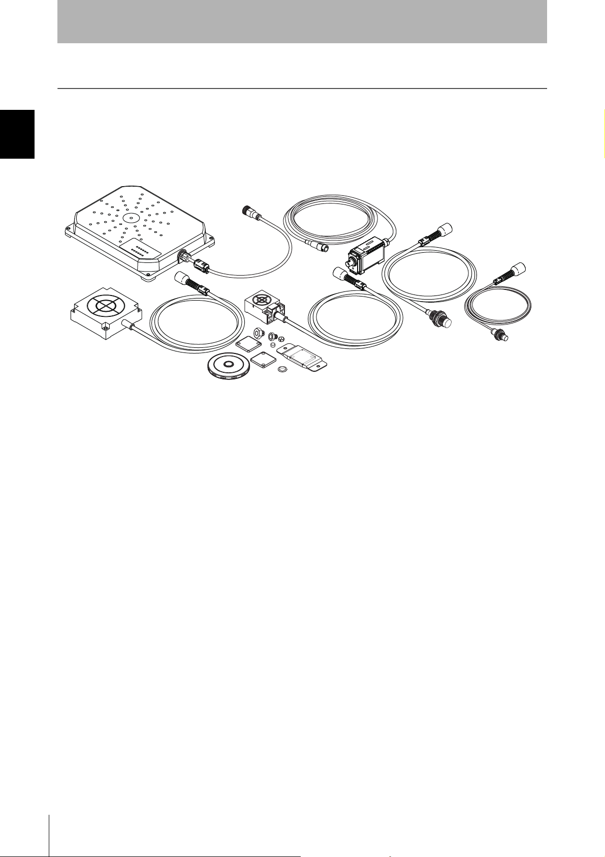
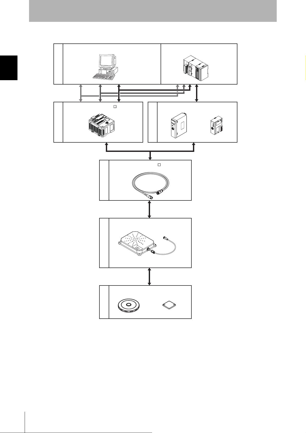
A V680-series RFID System consists of an ID Controller, one or more Amplifiers, one or two Antennas, and
RF Tags. Select the models suitable for the application.
Using Antennas with Separate Amplifiers
Host device
ID Controller
Personal computer Programmable Controller
RS-232C
RS-422 RS-485
V680-CA5D01-VV680-CA5D02-V CS1W-V680C11/12 CJ1W-V680C11/12
ID Sensor Units
V680-HA63A
(SYSMAC CS/CJ Series)
㪭
㪭
㪍
㪍
㪏㪇
㪏㪇
㪚
㪚
㪈
㪈
㪈
㪉
㪩
㪩
㪬
㪬
㪥
㪥
㪜
㪜
㪩
㪩
㪚
㪚
㪟
㪜㪘
㪛
㪜
㪜
㪈
㪩
㪩
㪧
㪧
㪫
㪫
㪆
㪆
㪥㪦㪩㪤㪆㪜㪩㪩
㪥㪦㪩㪤㪆㪜㪩㪩
㪜
㪜
㪩
㪩
㪩
㪩
㪟
㪟
㪟
㪜
㪘㪛
㪫
㪉
㪆
㪩
㪥㪦㪩㪤㪆㪜㪩㪩
㪫
㪫
㪜㪪
㪜
㪪
㪫
㪫
㪦
㪦
㪥
㪥
㪟
㪟
㪜
㪜
㪘㪛
㪘
㪛
㪈
㪈
㪛
㪟
㪚
㪜
㪉㪋
㪘
㪭
㪛
㪠㪥
㪉
㪧
㪬
㪫
㪂
㪄
Section 1 Product Configuration
Amplifiers
V680-HS51 V680-HS52 V680-HS63 V680-HS65
Antennas with Separate
Amplifier
V680-D1KP52MT V680-D1KP53M V680-D1KP66T-SPV680-D1KP54TV680-D1KP52MT-BT01/
-D1KP52MT-BT11
V680-D1KP66T/
-D1KP66MT
V680-D1KP58HTN
RF T ags
When embedding the V680-D1KP52MT and V680-D1KP53M into a metal surface, use the V680-HS51, V680-HS52 Antenna.
Transmission will not be possible if the V680-HS63 Antenna is used.
Use the V680-D1KP52MT, V680-D1KP52M-BT01, V680-D1KP52M-BT11, V680-D1KP53M, V680-D1KP54T, V680-D1KP66T,
V680-D1KP66MT, C680-D1KP66T-SP, and V680-D1KP58HTN RF Tags in combination with only the V680-HA63A Amplifier, Do
not use these RF Tags together with the V680-HA63B Amplifier.
RFID System
User's Manual
11
Page 14
Section 1 Product Configuration
RS-232C
CS1W-V680C11
V
6
8
0
C
1
1
R
U
N
E
R
C
T
/R
NORM/
ERR
E
R
P
E
R
H
T
E
S
T
O
N
H
E
A
D
1
CJ1W-V680C11
RS-422
RS-485
V680-H01-V2
* Always use the specified Cable to connect a
V680-H01-V2 Antenna. The V680-H01-V2
Antenna cannot be connected without using
the specified Cable.
Host device
Programmable Controller
(SYSMAC CS/CJ Series)
ID Controller
ID Sensor Units
Cable
Antennas with Built-in
Amplifier
RF T ags
V700-A40-W M
V680-CA5D01-V
Personal computer
V680-D1KP58HTN V680-D1KP66T
* When V680-H01-V2 is connected with
V680-CA1D/-CA2D, V680-D1KP66T cannot
be used.
Section 1
Product Overview
Using a V680-H01-V2 Antenna with Built-in Amplifier
12
RFID System
User's Manual
Page 15

Section 2 Specifications and Performance
Antennas with Separate Amplifier 14
Antennas with Built-in Amplifier 21
Amplifier 26
RF Tags 29
Section 2 Specifications and Performance
RFID System
User's Manual
13
Page 16

Section 2 Antennas with Separate Amplifier
Case material Brass
Communications
surface
ABS resin
Filling resin Epoxy resin
Cable PVC (black)
Section 2
Specifications and Performance
Antennas with Separate Amplifier
V680-HS51
General Specifications
Item Model V680-HS51
Ambient operating
temperature
Ambient storage
temperature
Ambient operating
humidity
Insulation resistance 20 MΩ min. (at 500 VDC) between connector terminals and case
Dielectric strength 1,000 VAC, 50/60 Hz for 1 min between connector terminals and case
Degree of protection IP67.(IEC60529)
Dielectric strength
Shock resistance
Dimensions M12 × 35 mm
Material ABS resin, brass, and epoxy resin filler
Weight Approx. 55 g
Cable length Standard lengths of 2 m
-10 to 60°C (with no icing)
-25 to 75°C (with no icing)
35% to 95% (with no condensation)
Oil resistance equivalent to IP67g according to the former JEM standard.
Note: The connectors are not waterproof.
10 to 2,000 Hz, 1.5-mm double amplitude, acceleration: 150 m/s
tions (up/down, left/right, and forward/backward) for 15 minutes each
2
1,000 m/s
, 3 times each in 6 directions (Total: 18 times)
2
, 10 sweeps in each of 3 axis direc-
Dimensions
• V680-HS51
12.5 dia.
Mounting Hole Dimensions
21 dia.
17
M12 × 1
9.6 dia.
(Unit : mm)
Toothed washer
Connector
(14.5 dia.)
Insulation cover
(16.8 dia.)
25
Ferrite core
26.2
50
Two lock nuts
12
7
24
33
35
Coaxial cable, 2.9 dia.,
standard length: 2 m
15
14
RFID System
User's Manual
Page 17

Specifications and Performance
Case material Brass
Communications
surface
ABS resin
Filling resin Epoxy resin
Cable PVC (gray)
V680-HS52
General Specifications
Item Model V680-HS52-W
(Standard cable, waterproof connector)
Ambient operating
temperature
Ambient storage
temperature
Ambient operating
humidity
Insulation resistance 20 MΩ min. (at 500 VDC) between connector terminals and case
Dielectric strength 1,000 VAC, 50/60 Hz for 1 min between connector terminals and case
Degree of protection IP67.(IEC60529)
Dielectric strength
Shock resistance
Dimensions M22 × 65 mm
Material ABS resin, brass, and epoxy resin filler
Weight Approx. 850 g (with 12.5 m cable)
Cable length Standard lengths of 2 and 12.5 m
-10 to 60°C (with no icing)
-25 to 75°C (with no icing)
35% to 95% (with no condensation)
Oil resistance equivalent to IP67g according to the
former JEM standard.
Note: The connector specifications are IP67 and
IP65.(IEC60529)
10 to 500 Hz, 1.5-mm double amplitude, acceleration: 100 m/s
(up/down, left/right, and forward/backward) for 8 minutes each
2
500 m/s
, 3 times each in 6 directions (Total: 18 times)
(Flexible cable, non-waterproof connector)
IP67.(IEC60529)
Oil resistance equivalent to IP67g according to the
former JEM standard.
Note: The connectors are not waterproof.
Section 2
V680-HS52-R
2
, 10 sweeps in each of 3 axis directions
Section 2 Antennas with Separate Amplifier
Dimensions
• V680-HS52-W
22.5 dia.
Mounting Hole Dimensions
Antenna
35 dia.
19.8 dia.
Two toothed washers
Two lock nuts
M22 × 1
16.5 dia.
Ferrite core
5030
37
Connector
16.5 dia.
14.5 dia.
Insulation cover
Operation indicator
730
47.6
50
57
65
Coaxial cable, 5.5 dia.,
standard length: 2 m
RFID System
User's Manual
15
Page 18

Section 2
Case material Brass
Communications
surface
ABS resin
Filling resin Epoxy resin
Cable PVC (black)
Specifications and Performance
• V680-HS52-R
Section 2 Antennas with Separate Amplifier
22.5 dia.
Mounting Hole Dimensions
Antenna
35 dia.
19.8 dia.
Two toothed washers
Two lock nuts
M22 × 1
16.5 dia.
Ferrite core
(39.5)
5030
Insulation cover
Connector
14.5 dia.
Insulation cover
16.5 dia.
Operation indicator
730
47.6
50
57
65
Coaxial cable, 5.3 dia.,
standard length: 2 m
16
RFID System
User's Manual
Page 19

V680-HS63
(Unit: mm)
23
5
5
Operation indicator
40
28±0.1
53
27 6
11
Note: Mounting Hole Dimensions
Coil center
Two, M4 or 4.5 dia. holes
37
5030
16.5 dia.
Coaxial cable, 5.5 dia.,
standard length: 2 m
Connector
Ferrite core
Insulation cover
16.5 dia.
14.5 dia.
Antenna
Case material ABS resin
Filling resin Epoxy resin
Cable PVC (gray)
General Specifications
Item Model V680-HS63-W
(Standard cable, waterproof connector)
Ambient operating
temperature
Ambient storage
temperature
Ambient operating
humidity
Insulation resistance 20 MΩ min. (at 500 VDC) between cable terminals and case
Dielectric strength 1,000 VAC, 50/60Hz for 1 min between cable terminals and case
Degree of protection IP67.(IEC60529)
Vibration resistance 10 to 500 Hz, 1.5-mm double amplitude, acceleration: 100 m/s
Shock resistance 500 m/s
Dimensions 40 × 53 × 23 mm
Material ABS resin case, epoxy resin filler
Weight Approx. 850 g (with 12.5 m cable)
Cable length Standard lengths of 2 and 12.5 m
-10 to 60°C (with no icing)
-25 to 75°C (with no icing)
35% to 95% (with no condensation)
IP67.(IEC60529)
Oil resistance equivalent to IP67g according to the
former JEM standard.
Note: The connector specifications are IP67 and
IP65.(IEC60529)
(up/down, left/right, and forward/backward) for 11 minutes each
2
, 3 times each in 6 directions (Total: 18 times)
Oil resistance equivalent to IP67g according to the
former JEM standard.
Note: The connectors are not waterproof.
Section 2
Specifications and Performance
V680-HS63-R
(Flexible cable, non-waterproof connector)
2
, 10 sweeps in each of 3 axis directions
Section 2 Antennas with Separate Amplifier
Dimensions
• V680-HS63-W
RFID System
User's Manual
17
Page 20

Section 2
Case material ABS resin
Filling resin Epoxy resin
Cable PVC (black)
Specifications and Performance
• V680-HS63-R
Antenna
Ferrite core
(39.5)
Connector
(Unit: mm)
Section 2 Antennas with Separate Amplifier
40
28±0.1
5
5
Operation indicator
23
Note: Mounting Hole Dimensions
Coil center
27 6
53
11
Two, M4 or 4.5 dia. holes
16.5 dia.
5030
Coaxial cable, 5.3 dia.,
standard length: 2 m
14.5 dia.
16.5 dia.
Insulation cover
18
RFID System
User's Manual
Page 21

Specifications and Performance
Operation indicator
30
20
11
(Unit: mm)
16.5 dia.
14.5 dia.
37
5030
16.5 dia.
Coaxial cable, 5.5 dia.,
standard length: 2 m
Connector
Ferrite core
Insulation cover
14
10
10
Bushing
50
25
100
90±0.25
50
100
90±0.2 5
4-4.5 dia.
(Mounting holes)
Case material ABS resin
Filling resin Epoxy resin
Cable PVC (gray)
V680-HS65
General Specifications
Item Model V680-HS65-W
(Standard cable, waterproof connector)
Ambient operating
temperature
Ambient storage
temperature
Ambient operating
humidity
Insulation resistance 20 MΩ min. (at 500 VDC) between connector terminals and case
Dielectric strength 1,000 VAC, 50/60 Hz for 1 min between connector terminals and case
Degree of protection IP67 (IEC60529)
Dielectric strength
Shock resistance
Dimensions 100 × 100 × 30 mm
Material ABS resin case, epoxy resin filler
Weight Approx. 1100 g (with 12.5 m cable)
Cable length Standard lengths of 2 and 12.5 m
−25 to 70°C (with no icing)
−40 to 85°C (with no icing)
35% to 95% (with no condensation)
Oil resistance equivalent to IP67g according to the
former JEM standard.
Note: The connector specifications are IP67 and
IP65 (IEC 60529).
10 to 500 Hz, 1.5-mm double amplitude, acceleration: 100 m/s
(up/down, left/right, and forward/backward) for 11 minutes each
2
500 m/s
, 3 times each in 6 directions (Total: 18 times)
(Flexible cable, non-waterproof connector)
IP67 (IEC60529)
Oil resistance equivalent to IP67g according to the
former JEM standard.
Note: The connectors are not waterproof.
Section 2
V680-HS65-R
2
, 10 sweeps in each of 3 axis directions
Section 2 Antennas with Separate Amplifier
Dimensions
• V680-HS65-W
RFID System
User's Manual
19
Page 22

Section 2 Antennas with Separate Amplifier
(39.5)
16.5 dia.
14.5 dia.
(Unit: mm)
5030
16.5 dia.
Coaxial cable, 5.3 dia.,
standard length: 2 m
Insulation cover
Connector
Ferrite core
Operation indicator
30
20
11
14
10
10
Bushing
50
25
100
90±0.25
50
100
90±0.2 5
4-4.5 dia.
(Mounting holes)
Case material ABS resin
Filling resin Epoxy resin
Cable PVC (black)
Section 2
Specifications and Performance
• V680-HS65-R
RFID System
20
User's Manual
Page 23

Antennas with Built-in Amplifier
V680-H01-V2
General Specifications
Item Model V680-H01-V2
Ambient operating
temperature
Ambient storage
temperature
Ambient operating
humidity
Insulation resistance 20 MΩ min. (at 100 VDC) between connector terminals and the rear plate
Dielectric strength 1,000 VAC, 50/60 Hz for 1 min between connector terminals and the rear plate
Degree of protection IP63.(IEC60529); Mounting direction: Communications surface facing up
Dielectric strength
Shock resistance
Cable length 0.5 m (use an relay cable to connect to the Controller up to 30.5 m)
LED indicators RUN, COMM, NORM, ERR, CNT-TYPE, TAG-TYPE, Error Code, Level
Weight Approx. 900 g
-10 to 55°C (with no icing)
-35 to 65°C (with no icing)
35% to 85% (with no condensation)
10 to 150 Hz, 0.35-mm single amplitude, acceleration: 50 m/s
(up/down, left/right, and forward/backward) for 8 minutes each
2
150 m/s
, 3 times each in 6 directions (Total: 18 times)
Section 2
Specifications and Performance
2
, 10 sweeps in each of 3 axis directions
Section 2 Antennas with Built-in Amplifier
Communications Specifications
Item Model V680-H01-V2
Communications method Electromagnetic induction
Operating frequency 13.56 MHz ± 7KHz
Modulation ASK
RFID System
User's Manual
21
Page 24

Section 2
Case material PC/ASA resin
Rear Panel Aluminum
Cable PVC
Specifications and Performance
Dimensions
MOUNTING SCREW HOLES
Senter of Coil
Section 2 Antennas with Built-in Amplifier
142.5
±0.2
235
65
(25-dia.)
50
Setting switch protection Cover
185±0.2
Four, M4 or 4.5-dia. holes
Twelve, Operation Indicator
Communications sufrace
200
185
Four, Mounting bracket
Vinyl Insulated Round Cord (5.8-dia.)
(41/0.16-dia.) 2 Cores (17/0.08-dia.) 8 Cores
Standard Length 0.5 m
Four, 5-dia. holes
(Mounting Holes)
6
30 38
142.5
235
250
7.5
(17)
(Unit : mm)
Connector
Ferrite Core
14 64.8
+50
500 0 (45)
20-dia.
(1)40
13.5
22
RFID System
User's Manual
Page 25

Operation Indicator
name Color Meaning
RUN Green Lit when the power is ON.
COMM Yellow Lit when a command is being sent.
NORM Green Lit when communications with a RF Tag are normal in Normal Communications
ERR Red Lit when an error occurs in communications with a RF Tag in Normal
CNT-TYPE Yellow Lit when in V680-CA1D/-CA2D Controller connection mode (SW1-1 setting: ON).
TAG-TYPE Yellow Lit when in V680-D@KF@@ RF Tag mode (SW1-2 setting: ON).
LV6/7D Yellow Maintenance Mode: Lit at distance or speed level 6.
LV5/7A Yellow Maintenance Mode: Lit at distance or speed level 5 or higher.
LV4/76 Yellow Maintenance Mode: Lit at distance or speed level 4 or higher.
LV3/72 Yellow Maintenance Mode: Lit at distance or speed level 3 or higher.
LV2/71 Yellow Maintenance Mode: Lit at distance or speed level 2 or higher.
LV1/70 Yellow Maintenance Mode: Lit at distance or speed level 1 or higher.
Section 2
Specifications and Performance
Mode.
Section 2 Antennas with Built-in Amplifier
Communications Mode.
Normal Communications Mode: Lit when a write protection error occurs.
Normal Communications Mode: Lit when an address error occurs.
Normal Communications Mode: Lit when a RF Tag memory error occurs.
Normal Communications Mode: Lit when a no RF Tag error occurs.
Normal Communications Mode: Lit when a verification error occurs.
Normal Communications Mode: Lit when a RF Tag communications error occurs.
The distance level will vary greatly depending on the surrounding environment. The setting position will serve as a
guide, but use RUN mode to conduct a sufficient number of tests in the actual operating environment.
Values of distance level 6 may not be displayed, but this will not affect the RUN mode performance and does not indicate a malfunction.
Differences between the V680-H01 and the V680-H01-V2
As shown in the following table, the V680-H01-V2 provides additional indicators.
Turn ON SW1-1(Antenna) when using the V680-CA1D/CA2D.
Only when the V680-D1KP58HTN is used, it is possible to set it.
display functions
RUN (POWER/COMM) OK OK OK
COMM (POWER/COMM) OK OK OK
NORM OK NO NO
ERR OK NO NO
CNT-TYPE OK OK NO
TAG-TYPE --- --- --LV6/7D OK NO NO
LV5/7A OK NO NO
LV4/76 OK NO NO
LV3/72 OK NO NO
LV2/71 OK NO NO
LV1/70 OK NO NO
SW1-1: OFF SW1-1: ON no switch
V680-H01-V2 V680-H01
RFID System
User's Manual
23
Page 26

Section 2
Note: Please attach a setting switch protection cover after setting switch.
Specifications and Performance
Setting Switch
Section 2 Antennas with Built-in Amplifier
Setting switch protection cover
Setting Function Default setting
SW1-1 Controller selection
OFF:V680-CA5D01-V@, CS1W-V680C11, or CJ1W-V680C11
ON: V680-CA1D/-CA2D
SW1-2 RF Tag selection
OFF:V680-D1KP@@ (EEPEOM RF Tags)
ON: V680-D@KF@@ (FRAM RF Tags)
SW1-3 Reserved by System (Always set this Switch to OFF.) --SW1-4 Reserved by System (Always set this Switch to OFF.) ---
Note: Only when the V680-D1KP58HTN is used, it is possible to connect it with the V680-CA1D/-CA2D.
When the V680-CA5D01-V@, CS1W-V680-C11 and CJ1W-V680C11 is used, set SW1-1 of the antenna to turning off.
See Note.
OFF
OFF
Set SW1-1 on the V680-H01-V2 Antenna and the Controller as shown in the following table.
When the V680-CA1D/-CA2D is used, set SW1-1 of the antenna to turning on.
When using it excluding the V680-CA1D/-CA2D, set SW1-1 of the antenna to turning off besides.
Antenna setting Controller setting
V680-H01-V2 V680-CA5D01-V@ CS1W-V680C11
CJ1W-V680C11
SW1-1: OFF SW4-8: OFF DM20000 + 100 × m+3=0000
SW1-1: ON SW4-8: ON
: Cannot be used.
: Can be used.(Controller setting not required.)
Note: The high-speed mode cannot be used by the controller's setting.
Differences between the V680-H01 and the V680-H01-V2
As shown in the following table, the V680-H01-V2 supports additional maintenance functions.
Turn ON SW1-1(Antenna) when using the V680-CA1D/CA2D.
Only when the V680-D1KP58HTN is used, it is possible to set it.
display functions
Communication Test Mode OK OK OK
Noise Level Measurement
Mode
Distance Level Measurement
Mode
Speed Level Measurement
Mode
Communications Success
Rate Measurement Mode
See Note.
DM20000 + 100 × m+3=0001
V680-H01-V2 V680-H01
SW1-1: OFF SW1-1: ON no switch
OK NO NO
OK NO NO
OK NO NO
OK NO NO
See Note. Å@See Note.
V680-CA1D
V680-CA2D
24
RFID System
User's Manual
Page 27

Section 2
Connector (Antenna end))
Connector (Controller end))
Connection label
Vinyl Insulated Round Cord
6 dia.
20 dia.
41.8
L1
±100
49
(Unit: mm)
15 dia.
Cable PVC
Specifications and Performance
Cables (V680-H01-V2 exclusive use)
Specifications
Item Model V700-A40-W
Number of conductors 10
Insulation resistance 5 MΩ min. (at 500 VDC) between terminals and sheath
Dielectric strength 500 VAC, 1 min
Dimensions
Item Model V700-A40-W 2M V700-A40-W 5M V700-A40-W 10M V700-A40-W 20M V700-A40-W 30M
Length (L1) Approx.2m Approx. 5 m Approx.10m Approx. 20 m Approx. 30 m
Weight Approx. 150 g Approx.360 g Approx. 700 g Approx.1,350 g Approx.2,000 g
L1 2,000 5,000 10,000 20,000 30,000
Section 2 Antennas with Built-in Amplifier
RFID System
User's Manual
25
Page 28

Section 2 Amplifier
Operation indicator
13.7 65 18
51
36
15 dia.
40
25
9.5 dia.
25
3.5
12.8 dia.
15 35.6
25
Round, vinyl-insulated cable (5.8 dia.), standard length: 5 m,
(41/0.16 dia) 2 conductors, (17/0.08 dia.) 8 conductors
Connector
Connector
Case material PC resin
Cable PVC
Section 2
Specifications and Performance
Amplifier
V680-HA63A
General Specifications
Item Model V680-HA63A
Ambient operating
temperature
Ambient storage
temperature
Ambient operating
humidity
Insulation resistance 20 MΩ min. (at 500 VDC) between cable terminals and case
Dielectric strength 1,000 VAC, 50/60 Hz for 1 minute between cable terminals and case.
Degree of protection IP67, IP65 (IEC 60529)
Dielectric strength
Shock resistance 500 m/s
Dimensions 25 × 40 × 65 mm (Not including protrusions.)
Materials PC
Weight Approx. 650 g (with 10 m cable)
Cable length Standard lengths of 5 and 10 m
Note: The maximum total cable extension is 50 m (including the Amplifier cable). A maximum of two extension cables can be
connected.
-10 to 55°C (with no icing)
-25 to 65°C (with no icing)
35% to 85% (with no condensation)
Note: Not including connector at Controller end.
(When V680-HS52-W, V680-HS63-W, and V680-HS65-W
is connected)
10 to 500 Hz, 1.5-mm double amplitude, acceleration:100 m/s
(up/down, left/right, and forward/backward) for 11 minutes each
2
, 3 times each in 6 directions (Total: 18 times)
IP40 (IEC 60529)
(When V680-HS51, V680-HS52-R, V680HS63-R, and V680-HS65-R is connected)
2
, 10 sweeps in each of 3 axis directions
Dimensions
26
RFID System
User's Manual
Page 29

Nomenclature
Section 2
Specifications and Performance
Antenna with Separate Amplifier connection port
RUN
COMM
NORM
ERR
LV6/7D
LV5/7A
LV4/76
LV3/72
Operation indicators
LV2/71
LV1/70
Controller connector
Antenna Connection Port
The Antenna connection port is connected a V680-series Antenna.
Controller Connector
The Controller connector is connected to Antenna connection port on the Controller.
Section 2 Amplifier
Operation Indicators (LEDs)
Name Color Meaning
RUN Green Lit when the power is ON.
COMM Yellow Lit when a command is being sent.
NORM Green Lit when communications with a RF Tag are normal in Normal Communications Mode.
ERR Red Lit when an error occurs in communications with a RF Tag in Normal Communications Mode.
LV6/7D Yellow
LV5/7A Yellow
LV4/76 Yellow
LV3/72 Yellow
LV2/71 Yellow
LV1/70 Yellow
The distance level will vary greatly depending on the surrounding environment. The setting position will serve as a
guide, but use RUN mode to conduct a sufficient number of tests in the actual operating environment.
Values of distance level 4 or above may not be displayed, but this will not affect the RUN mode performance and does
not indicate a malfunction.
Maintenance Mode: Lit at distance or speed level 6.
Normal Communications Mode: Lit when a write protection error occurs.
Maintenance Mode: Lit at distance or speed level 5 or higher.
Normal Communications Mode: Lit when an address error occurs.
Maintenance Mode: Lit at distance or speed level 4 or higher.
Normal Communications Mode: Lit when a RF Tag memory error occurs.
Maintenance Mode: Lit at distance or speed level 3 or higher.
Normal Communications Mode: Lit when a no RF Tag error occurs.
Maintenance Mode: Lit at distance or speed level 2 or higher.
Normal Communications Mode: Lit when a verification error occurs.
Maintenance Mode: Lit at distance or speed level 1 or higher.
Normal Communications Mode: Lit when a RF Tag communications error occurs.
RFID System
User's Manual
27
Page 30

Section 2 Amplifier
51 L1
±100
49
15.5 dia.
Connector (Controller end))
Connection label
Connector (Amplifier end)
6 dia.
15 dia.
(Unit: mm)
Cable PVC
Section 2
Specifications and Performance
Cables (V680-HA63 exc lusive use)
Specifications
Item Model V700-A43/V700-A44
Number of conductors 10
Insulation resistance 5 MΩ min. (at 500 VDC) between terminals and sheath
Dielectric strength 500 VAC, 1 min
Dimensions
Item Model V700-A43 V700-A44
Length (L1) Approx.10m Approx. 20 m
Weight Approx. 700 g Approx.1,350 g
28
RFID System
User's Manual
Page 31

RF Tags
8
0
−0.1
R0.2
5
0
−0.1
dia.
(Unit : mm)
Case material PPS resin
Filling resin Epoxy resin
Specifications and Dimensions
V680-D1KP52MT
• General Specifications
Item Model V680-D1KP52MT
Memory capacity 1,000 bytes (user area)
Memory type EEPROM
Data Retention 10 years after writing (85°C or less), 0.5 years after writing (85°C to 125°C)
Write Endurance 100,000 times per block (25°C)
Ambient operating
temperature when
communicating
Ambient storage
temperature (with data
retention)
Ambient operating
humidity
Degree of protection IP68 (IEC 60529)
Vibration resistance
Shock resistance 500 m/s
Dimensions 8 dia. × 5 mm
Materials Case: PPS resin, Filling resin: Epoxy resin
Weight Approx. 0.5 g
Metal countermeasures Yes
Specifications and Performance
Total data retention at high temperatures exceeding 125°C is 10 hours (See note.)
-25 to 85°C (with no icing)
-40 to 125°C (with no icing)
35% to 95%
Oil resistance equivalent to IP67g according to the former JEM standard.
10 to 2,000 Hz, 1.5-mm double amplitude, acceleration: 150 m/s
directions for 15 minutes each
2
, 3 times each in X, Y, and Z directions (Total: 18 times)
2
, 10 sweeps each in X, Y, and Z
Section 2
Section 2 RF Tags
Note: After string data at high temperatures, rewrite the data even if changes are not required, high temperatures
are those exceeding 125°
C up to 180°C.
• Dimensions
When embedding the V680-D1KP52MT into a metal surface, use the V680-HS51, V680-HS52 Antenna.
Transmission will not be possible if the V680-HS63 Antenna is used.
The side with the markings is the communications surface. Mount the RF Tag with this side facing the Antenna.
The ID code is written in the memor y of the R F Tag and may be affected by data retention characteristics at high temperatures. Take suitable precautions when using the READ ID command for RF Tags operating at high temperatures.
RFID System
User's Manual
29
Page 32

Section 2
Specifications and Performance
• RF Tag Heat Resistivity
• Storing RF Tags under high temperatures or heat cycle will adversely affect the performance of the
internal parts and the service life of the RF Tags.
• An LTPD of 10% was determined during the evaluation for RF Tags that reached the end of their life
after testing under the following test conditions.
Section 2 RF Tags
Heat cycle -10°C/+150°C, 30 minutes each for 1,000 cycles: Defective number 0/22 piece
-100°C/+180°C,30 minutes each for 200 cycles: Defectiv e number 0/22 piece
High temperatures +150°C, 1,000 hours: Defective number 0/22 piece
+180°C, 200 hours: Defective number 0/22 piece
LTPD: Lot tolerance percent defective
The lower limit of the malfunction rate for lots to be considered unacceptable during reliability testing.
30
RFID System
User's Manual
Page 33

Specifications and Performance
V680-D1KP52M-BT01
• General Specifications
Item Model V680-D1KP52M-BT01
Memory capacity 1,000 bytes (user area)
Memory type EEPROM
Data Retention 10 years after writing (85°C or less), 0.5 years after writing (85°C to 125°C)
Total data retention at high temperatures exceeding 125°C is 10 hours (See note.)
Write Endurance 100,000 times per block (25°C)
Ambient operating
temperature when
communicating
Ambient storage
temperature (with data
retention)
Ambient operating
humidity
Degree of protection IP68 (IEC 60529)
Vibration resistance
Shock resistance 500 m/s
Dimensions Hex Head: 17HEX × 9.5 mm, Screw: M10 × 10 mm
Materials Bolt: SUS303, Case(RF Tag): PPS resin, Filling resin(RF Tag): Epoxy resin
Weight Approx. 25 g
Metal countermeasures Yes
-25 to 85°C (with no icing)
-40 to 125°C (with no icing)
35% to 95%
Oil resistance equivalent to IP67g according to the former JEM standard.
10 to 2,000 Hz, 1.5-mm double amplitude, acceleration: 150 m/s
directions for 15 minutes each
2
, 3 times each in X, Y, and Z directions (Total: 18 times)
Section 2
2
, 10 sweeps each in X, Y, and Z
Section 2 RF Tags
• Dimensions
The side with the markings is the communications surface. Mount the RF Tag with this side facing the Antenna.
The ID code is written in the memor y of the R F Tag and may be affected by data retention characteristics at high temperatures. Take suitable precautions when using the READ ID command for RF Tags operating at high temperatures.
RF T ag
(19.6)
17
Bolt
15-30
8.4 dia.
M10-P1.5
C1.5
0.1 9.5 10
21.6
Bolt material SUS303
Case material (RF Tag) PPS resin
Filling resin (RF Tag) Epoxy resin
(Unit: mm)
RFID System
User's Manual
31
Page 34

Section 2 RF Tags
Section 2
Specifications and Performance
V680-D1KP52M-BT11
• General Specifications
Item Model V680-D1KP52M-BT11
Memory capacity 1,000 bytes (user area)
Memory type EEPROM
Data Retention 10 years after writing (85°C or less), 0.5 years after writing (85°C to 125°C)
Total data retention at high temperatures exceeding 125°C is 10 hours (See note.)
Write Endurance 100,000 times per block (25°C)
Ambient operating
temperature when
communicating
Ambient storage
temperature (with data
retention)
Ambient operating
humidity
Degree of protection IP68 (IEC 60529)
Vibration resistance
Shock resistance 500 m/s
Dimensions Hex Head: 13HEX × 7 mm, Screw: M8 × 10 mm
Materials Bolt: SUS303, Case(RF Tag): PPS resin, Filling resin(RF Tag): Epoxy resin
Weight Approx. 10 g
Metal countermeasures Yes
-25 to 85°C (with no icing)
-40 to 125°C (with no icing)
35% to 95%
Oil resistance equivalent to IP67g according to the former JEM standard.
10 to 2,000 Hz, 1.5-mm double amplitude, acceleration: 150 m/s
directions for 15 minutes each
2
, 3 times each in X, Y, and Z directions (Total: 18 times)
2
, 10 sweeps each in X, Y, and Z
• Dimensions
The side with the markings is the communications surface. Mount the RF Tag with this side facing the Antenna.
The ID code is written in the memor y of the R F Tag and may be affected by data retention characteristics at high temperatures. Take suitable precautions when using the READ ID command for RF Tags operating at high temperatures.
RF T ag
(15)
13
Bolt
15-30
6 dia.
M8-P1.25
C1.5
0.1 7 10
19.1
Bolt material SUS303
Case material (RF Tag) PPS resin
Filling resin (RF Tag) Epoxy resin
(Unit: mm)
32
RFID System
User's Manual
Page 35

Specifications and Performance
C0.5
6-R0.8
10 dia.
4.5
V680-D1KP53M
General Specifications
Item Model V680-D1KP53M
Memory capacity 1,000 bytes (user area)
Memory type EEPROM
Data Retention 10 years after writing (85°C or less), 0.5 years after writing (85 to 125°C)
Write Endurance 100,000 times per block (25°C)
Ambient operating
temperature when
communicating
Ambient storage
temperature (with data
retention)
Ambient operating
humidity
Degree of protection IP68 (IEC 60529)
Vibration resistance 10 to 2,000 Hz, 1.5-mm double amplitude, acceleration: 150 m/s
Shock resistance 500 m/s
Dimensions 10 dia. × 4.5 mm (DIN698373)
Materials Case: PPS resin, Filling resin: Epoxy resin
Weight Approx. 1.0 g
Metal countermeasures Yes
−25 to 85°C (with no icing)
−40 to 125°C (with no icing)
35% to 95%
Oil resistance equivalent to IP67g according to the former JEM standard.
directions for 15 minutes each
2
, 3 times each in X, Y, and Z directions (Total: 18 times)
Section 2
2
, 10 sweeps each in X, Y, and Z
Section 2 RF Tags
Dimensions
When embedding the V680-D1KP53M into a metal surface, use the V680-HS51, V680-HS52 Antenna.
Transmission will not be possible if the V680-HS63 Antenna is used.
The side with the markings is the communications surface. Mount the RF Tag with this side facing the Antenna.
Case material PPS resin
Filling resin Epoxy resin
RFID System
User's Manual
33
Page 36

Section 2 RF Tags
Case material PPS resin
1.1
2.7
±0.1
16 dia.
±0.1
20 dia.
±0.1
(Unit : mm)
Section 2
Specifications and Performance
V680-D1KP54T
• General Specifications
Item Model V680-D1KP52MT
Memory capacity 1,000 bytes (user area)
Memory type EEPROM
Data Retention 10 years after writing (85°C or less), 0.5 years after writing (85°C to 125°C)
Total data retention at high temperatures exceeding 125°C is 10 hours (See note.)
Write Endurance 100,000 times per block (25°C)
Ambient operating
temperature when
communicating
Ambient storage
temperature (with data
retention)
Ambient operating
humidity
Degree of protection IP67 (IEC 60529)
Vibration resistance
Shock resistance 500 m/s
Dimensions 20 dia. × 2.7 mm
Materials PPS resin
Weight Approx. 2.0 g
Metal countermeasures None
-25 to 85°C (with no icing)
-40 to 125°C (with no icing)
35% to 95%
Oil resistance equivalent to IP67g according to the former JEM standard.
10 to 2,000 Hz, 1.5-mm double amplitude, acceleration: 150 m/s
directions for 15 minutes each
2
, 3 times each in X, Y, and Z directions (Total: 18 times)
2
, 10 sweeps each in X, Y, and Z
Note: After string data at high temperatures, rewrite the data even if changes are not required, high temperatures
are those exceeding 125°
C up to 180°C.
Dimensions
V680-D1KP54T
The coin-shaped RF Tag has no directionality, so it can be faced in any direction.
The ID code is written in the memor y of the R F Tag and may be affected by data retention characteristics at high temperatures. Take suitable precautions when using the READ ID command for RF Tags operating at high temperatures.
34
RFID System
User's Manual
Page 37

V600-A86 Attachment
Material PPS resin
40
31
±0.2
T
w
o,
6
d
i
a
.
T
w
o
,
2
0
d
i
a
.
(
M
o
u
n
t
i
n
g
H
o
l
e
)
.
(Unit : mm)
24
18
22
22
5
8
3.5
1
Section 2
Specifications and Performance
Section 2 RF Tags
• RF Tag Heat Resistivity
• Storing RF Tags under high temperatures or heat cycle will adversely affect the performance of the
internal parts and the service life of the RF Tags.
• An LTPD of 10% was determined during the evaluation for RF Tags that reached the end of their life
after testing under the following test conditions.
Heat cycle -10°C/+150°C, 30 minutes each for 1,000 cycles: Defective number 0/22 piece
-100°C/+180°C,30 minutes each for 200 cycles: Defectiv e number 0/22 piece
High temperatures +150°C, 1,000 hours: Defective number 0/22 piece
+180°C, 200 hours: Defective number 0/22 piece
LTPD: Lot tolerance percent defective
The lower limit of the malfunction rate for lots to be considered unacceptable during reliability testing.
RFID System
User's Manual
35
Page 38

Section 2 RF Tags
V680-D1KP66MT V680-D1KP66T
MADE IN JAPAN
XXXXXX
V680-D1KP66MT
MADE IN JAPAN
XXXXXX
V680-D1KP66T
Section 2
Specifications and Performance
V680-D1KP66T/66MT
• General Specifications
Item Model V680-D1KP66T V680-D1KP66MT
Memory capacity 1,000 bytes (user area)
Memory type EEPROM
Data Retention 10 years after writing (85°C or less), 0.5 years after writing (85°C to 125°C)
Total data retention at high temperatures exceeding 125°C is 10 hours (See note.)
Write Endurance 100,000 times per block (25°C)
Ambient operating
temperature
Ambient storage
temperature
Ambient operating
humidity
Degree of protection IP68 (IEC 60529)
Vibration resistance
Shock resistance 500 m/s
Dimensions 34 × 34 × 3.5 mm
Materials Case: PPS resin
Weight Approx. 6 g Approx. 7.5 g
Metal countermeasures None Yes
-25 to 85°C (with no icing)
-40 to 125°C (with no icing)
35% to 95%
Oil resistance equivalent to IP67g according to the former JEM standard.
2
10 to 2,000 Hz, 1.5-mm double amplitude, acceleration: 150 m/s
directions for 15 minutes each
2
, 3 times each in X, Y, and Z directions (Total: 18 times)
,10 sweeps each in X, Y, and Z
Note: After string data at high temperatures, rewrite the data even if changes are not required, high temperatures
are those exceeding 125°
C up to 180°C.
The V680-D1KP66MT is designed to be mounted directly to metal. The V680-D1KP66T and V680D1KP66MT markings are shown in the f ollowing diagrams.
The side with the markings is the communications surface. Mount the RF Tag with this side facing the Antenna.
The ID code is written in the memor y of the R F Tag and may be affected by data retention characteristics at high temperatures. Take suitable precautions when using the READ ID command for RF Tags operating at high temperatures.
RFID System
36
User's Manual
Page 39

• Dimensions
25+0.2
25+0.2
25+0.2
25+0.2
3.5+0.1
Two, M3
Four, R3
Four, R4
32
32
34
34
Mounting Hole Dimensions
Two, 3.5 dia.
Two, 6 dia.
Case material PPS resin
25+0.2
25+0.2
25+0.2
25+0.2
16
4
10
3.5
3737343415
15
Two, M3
Two, 4 dia.
Four, R5.5
Case material PPS resin
V680-D1KP66T/66MT
V600-A86 Attachment
Section 2
Specifications and Performance
Section 2 RF Tags
• RF Tag Heat Resistivity
• Storing RF Tags under high temperatures or heat cycle will adversely affect the performance of the
internal parts and the service life of the RF Tags.
• An LTPD of 10% was determined during the evaluation for RF Tags that reached the end of their life
after testing under the following test conditions.
Heat cycle -10°C/+150°C, 30 minutes each for 1,000 cycles: Defective number 0/22 piece
-100°C/+180°C,30 minutes each for 200 cycles: Defectiv e number 0/22 piece
High temperatures +150°C, 1,000 hours: Defective number 0/22 piece
+180°C, 200 hours: Defective number 0/22 piece
LTPD: Lot tolerance percent defective
The lower limit of the malfunction rate for lots to be considered unacceptable during reliability testing.
RFID System
User's Manual
37
Page 40

Section 2 RF Tags
(Unit: mm)
Section 2
Specifications and Performance
V680-D1KP66T-SP
• General Specifications
Item Model V680-D1KP66T-SP
Memory capacity 1,000 bytes (user area)
Memory type EEPROM
Data Retention 10 years after writing (85°C or less)
Write Endurance 100,000 times per block (25°C)
Ambient operating
temperature when
communicating
Ambient operating
temperature when not
communicating
Ambient storage
temperature
Ambient operating
humidity
Degree of protection IP67
Vibration resistance
Shock resistance 500 m/s
Dimensions 95 × 36.5 × 6.5 mm (excluding protruding parts)
Materials External coatiog: Fluororesin (PFA)
Weight Approx. 20 g
Mounting method Two M5 screws
Metal countermeasures None
-25 to 70°C (with no icing)
-40 to110°C (with no icing)
-40 to 110°C (with no icing)
35% to 95%
10 to 2,000 Hz, 1.5-mm double amplitude, acceleration: 150 m/s
directions for 15 minutes each
2
, 3 times each in X, Y, and Z directions (Total: 18 times)
RF Tag body: PPS resin
2
,10 sweeps each in X, Y, and Z
• Dimensions
Four, R6
3436.5
6.5 2.5 max.
The side with the markings is the communications surface. Mount the RF Tag with this side facing the Antenna.
34
80±0.2
95
Two, 5.5 dia.
(Mounting hole)
1.3
Mounting Hole Dimensions
Two, M5
80±0.2
PFA resinCase material
38
RFID System
User's Manual
Page 41

Specifications and Performance
(Unit: mm)
Case material PPS resin
Mounting Hole Dimensions
20 dia.
M12
M12
4050
11.5
15
110
3.2 dia.
12 dia.
17
2
1
Nuts (M12):
Provided Parts
Split pin (3.2 × 20 mm):
(Unit: mm)
V680-D1KP58HTN
• General Specifications
Item Model V680-D1KP58HTN
Memory capacity 1,000 bytes (user area)
Memory type EEPROM
Data Retention 10 years after writing (85°C or less), 0.5 years after writing (85°C to 125°C)
Total data retention at high temperatures exceeding 125°C is 10 hours
Write Endurance 100,000 times per block (25°C)
Ambient operating
temperature
Ambient storage
temperature
Ambient operating
humidity
Degree of protection IP67 (IEC 60529)
Vibration resistance
Shock resistance 500 m/s
Materials Coatiog: PPS resin
Weight Approx. 70 g
-25 to 85°C (with no icing)
-40 to 250°C (with no icing)
(Data retention: -40 to 125°C)
35% to 95%
Oil resistance equivalent to IP67g according to the former JEM standard.
10 to 2,000 Hz, 1.5-mm double amplitude, acceleration: 150 m/s
directions for 15 minutes each
2
, 3 times each in X, Y, and Z directions (Total: 18 times)
Section 2
2
,10 sweeps each in X, Y, and Z
Section 2 RF Tags
• Dimensions
V680-D1KP58HTN
10±0.2
7.51.25
䋨60 dia.䋩
80 dia.
14 dia.
䋨5°䋩
V680-A80 (Attachment)
This Attachment is specifically designed to secure V680-D1KP58 H TN RF Tags to the workpiece.
Applicable RF Tag model: V680-D1KP58HTN
䋨1.25䋩
䋨5°䋩
18 dia.
Two, R1
RFID System
User's Manual
39
Page 42

Section 2 RF Tags
1 hour
at 2
5°
C
1 hour
at 25°C
3 hours
at 25°C
2 hours
at 25°C
1 hours
at 25°C
3 hours
at 25°C
㪘㪺㪺㫌㫄㫌㫃㪸㫋㪼㪻㩷㫋㫀㫄㪼䋺㩷㪈㩷㪿㫆㫌㫉
㪘㪺㪺㫌㫄㫌㫃㪸㫋㪼㪻㩷㫋㫀㫄㪼䋺㩷㪋㩷㪿㫆㫌㫉㫊
㪮㫉㫀㫋㫀㫅㪾㩷㪻㪸㫋㪸㩷㫋㫆㩷㫋㪿㪼㩷㪩㪝㩷㫋㪸㪾㩷
㫄㪼㫄㫆㫉㫐㩷㫀㫅㩷㫌㫊㪼㪅
Reset the data
retention time.
Leaving time other than high temperature environment
is not included in the cumulative time used.
*1.
*1. High temperatures are those exceeding 125°C up to 250°C.
Reset the data
retention time.
Fig. Concept of resetting the data retention time
1 hour at high
temperatures
*1.
3 hours at high
temperatures
2 hours at high
temperatures
*1. *1.
3 hours at high
temperatures
2 hours at high
temperatures
*1.
㪘㪺㪺㫌㫄㫌㫃㪸㫋㪼㪻㩷㫋㫀㫄㪼䋺㩷㪍㩷㪿㫆㫌㫉㫊
㪘㪺㪺㫌㫄㫌㫃㪸㫋㪼㪻㩷㫋㫀㫄㪼䋺㩷㪐㩷㪿㫆㫌㫉㫊
㪘㪺㪺㫌㫄㫌㫃㪸㫋㪼㪻㩷㫋㫀㫄㪼䋺㩷㪋㩷㪿㫆㫌㫉㫊
Section 2
Specifications and Performance
Use at high temperatures (V680-D1KP58HTN)
Data retention
• Data stored in memory in the RF Tag may be lost due to the characteristics of EEPROM, if the accumulated usage time of the RF Tag at a high temperature over 1 25
the RF Tag. Reset the data retention time before the accumulated usage time ex ceeds 10 hours.
• An error in communications between the Antenna and the RF Tag may occur in an environment where
the ambient operating temperature is 85
°
C or higher. Do not communicate between the Antenna and
the RF Tag in an environment where the ambient operating temperature is 85
• The UID (unique identification number for each RF Tag) may be lost due to the characteristics of
EEPROM when the RF tag is used at a high temperature over 125°C. Do not use the commands
using UID at a high temperature over 125°C.
•Do not use the READ ID command (command code: ID).
•Do not make the UID Addition Setting (command code: US).
•Communications specifications (FIFO trigger, FIFO repeat, multi-access trigger, multi-access repeat,
and selective) can not be used.
• Accumulated time
°
C exceeds 10 hours af te r writing data to
°
C or higher.
40
• Resetting the data retention time
<When using the RF Tag addresses 0010Hex to 0015Hex.>
1.Reading data from the RF tag addresses 0010Hex to 0015Hex.
Command : RDSTH100100006*[CR]
Reseponse : RD0010001122334455*[CR]
2.Read data written to the RF tag addresses 0010Hex to
0015Hex..
Command : WTSTH10010001122334455*[CR]
RFID System
User's Manual
Reseponse : WT0010*[CR]
Data retention is reset only data written to the RF tag address.
If you reset the data retention, writes the same data to all of the tag memory in use.
<RF tag memory>
Hex
0010
Hex
0011
Hex
0012
Hex
0013
Hex
0014
Hex
0015
Read data written to the RF
tag memory in use.
Hex
00
Hex
11
Hex
22
Hex
33
Hex
44
Hex
55
Reading data from the RF
tag memory in use.
<RF tag memory>
Hex
Hex
Hex
Hex
Hex
Hex
00
11
22
33
44
55
Hex
Hex
Hex
Hex
Hex
Hex
0010
0011
0012
0013
0014
0015
Page 43

Section 2
Specifications and Performance
Heat Resistance
Storing RF Tags under high temperatures or heat cycle will adversely affect the performance of the
internal parts and the service life of the RF Tags.
Correct operation has been confirmed through the OMRON in-house evaluation for RF Tags under the
following high-te mperature conditions.
1) 2,000 cycles, where 1 cycle is each 30-minute at Room temperature and 200°C
2) 250°C, 500 hours
The controller’s setting
Please set the latest ID controller to the CA1D mode and use it when the latest ID controller is used
together with the old model ID controller Model V680-CA1D/- CA2D.
Section 2 RF Tags
RF Tag
Controller
V680-CA1D/-CA2D only Not required Not required Not required
C680-CA1D/-CA2D and the latest
ID controller used together
The latest ID controller only Not required Not required Not required
Note: The latest ID controller:
V680-CA5D01-V2/-CA5D02-V2
V680-CH1D/CHUD/-CH1D-PSI
CS1W-V680C11/-V680C12
CJ1W-V680C11/-V680C12
V680-D1KP58HT only
Not required Set the latest ID controller to
V680-D1KP58HT and V680-
D1KP58HTN used together
the CA1D mode.
V680-D1KP58HTN only
Set the latest ID controller to
the CA1D mode.
RFID System
User's Manual
41
Page 44

Section 2
Specifications and Performance
Memory Map
Section 2 RF Tags
Address
Data
0000 H
0001 H
0002
0003 H
03E6
H
User area
H
03E7 H
1 byte
EEPROM is used as memory in the RF Tags.
The memory capacity availab l e to t he use r is 1, 000 bytes, including 0000H to 0003 H (t he Write Protection Setting Area).
The access to the memory is executed at every block.
1 block is 8 bytes (8 addresses).
The communication between RF Tag and the antenna of the V680 series is a block unit (8bytes).
There is a possibility to which data is mistaken with the block unit when the writing error occurs.
42
RFID System
User's Manual
Page 45

Section 2
Specifications and Performance
Write Protection Function
The write protection function prevents important data, such as product information, stored in memory
in a RF Tag from being inadvertently overwritten.
After important data has been written to memory, it can be write-protected using the following method.
The write protection function can be switched with SW4-7 (Write Protection Function Setting) of the V680-CA5D@@-V@
Controller or with word (Write Protection Function Setting) in the DM(m+2)CH Area words allocated to the C@1W-
V680C@@ ID Sensor Unit.
Refer to the V680 Series User’s Manual (Cat. No. Z249) for details.
Setting the Write Protection Function
Write protection is set in RF Tag addresses 0000H to 0003H.
The setting for the most significant bit of address 0000H specifies whether or not write protection is enabled.
Address Bit 7 6 5 4 3 2 1 0
H
0000
H Lower two digits of start address (00H to FFH)
0001
H Upper two digits of end address (00H to FFH)
0002
0003
H Lower two digits of end address (00H to FFH)
• Write-protect Bit (Most significant bit of address 0000H)
1: Write-protected (Yes)
0: Not write-protected (No)
YES/
Upper two digits of start address (00H to 7FH)
NO
Section 2 RF Tags
• Write Protection Setting Area
Start address: 0000
H to 7FFFH
End address: 0000H to FFFFH
RFID System
User's Manual
43
Page 46

Section 2 RF Tags
Section 2
Specifications and Performance
Write Protection Setting Examples
• Settings to write-protect addresses 0008H through 03E7H:
Address Bit 7 6 5 4 3 2 1 0
0000
H
H
0001
H
0002
0003
H
• Settings to not write-protect any addresses:
Address Bit 7 6 5 4 3 2 1 0
0000
H
0001
H
0002
H
0003
H
10000000
80
00001000
08
00000011
03
11100111
E7
00000000
00
00000000
00
00000000
00
00000000
00
The write protection function is a function of the V680-CA5D@@-V@ Controller and the C@1W-V680C@@ ID Sensor
Unit. It is not supported by reader/writer units from other manufacturers.
44
RFID System
User's Manual
Page 47

Section 3 Communications Specifications
Communications Distances 46
Communication Time (Reference) 60
Section 3 Communications Specifications
RFID System
User's Manual
45
Page 48

Section 3
V680-HS52
Metal
V680-HS63
V680-HS52
Non-metallic material
(Exmamples: Resin, plastic, wood, etc.)
Non-metallic material
Metal
V680-HS51 V680-HS51
V680-D1KP52MT
Metal
Non-metallic materialNon-metallic material
Metal
V680-D1KP52MT
Non-metallic material
(Exmamples: Resin, plastic, wood, etc.)
Non-metallic material
(Exmamples: Resin, plastic, wood, etc.)
Communications
distance
Communications
distance
Communications
distance
Communications
distance
Communications
distance
V680-D1KP52MT
V680-D1KP52MT
V680-D1KP52MT
Communications Specifications
Communications Distances
V680-D1KP52MT
Communications Distance Specifications (Guaranteed)
Amplifier Antenna RF Tag Communications distance
V680-HS51 V680-D1KP52MT
V680-HS51
V680-D1KP52MT
embedded in metal (steel)
Section 3 Communications Distances
V680-HA63A
When embedding the V680-D1KP52MT into a metal surface, use the V680-HS51, V680-HS52 Antenna.
Transmission will not be possible if the V680-HS63 Antenna is used.
V680-HS52 V680-D1KP52MT
V680-HS52
V680-HS63 V680-D1KP52MT
V680-D1KP52MT
embedded in metal (steel)
Read 0.5 to 6.5 mm (Axis offset: ±2 mm)
Write 0.5 to 6.0 mm (Axis offset: ±2 mm)
Read 0.5 to 3.5 mm (Axis offset: ±2 mm)
Write 0.5 to 3.0 mm (Axis offset: ±2 mm)
Read 0 to 9.0 mm (Axis offset: ±2 mm)
Write 0 to 8.5 mm (Axis offset: ±2 mm)
Read 0 to 4.5 mm (Axis offset: ±2 mm)
Write 0 to 4.0 mm (Axis offset: ±2 mm)
Read 0 to 12.0 mm (Axis offset: ±2 mm)
Write 0 to 9.5 mm (Axis offset: ±2 mm)
• Measurement Conditions
RFID System
46
User's Manual
Page 49

Section 3
20
30
10
Y
-40 -30 -20 -10 10 20 30 X0
20
30
10
Y
-40 -30 -20 -10 10 20 30 X0
20
30
10
Y
-40 -30 -20 -10 10 20 30 X0
20
30
10
Y
-40 -30 -20 -10 10 20 30 X0
20
30
10
Y
-40 -30 -20 -10 10 20 30 X0
Read
Write
(Embedded in Metal: Steel)
V680-HS51䋨Embedded in Metal䋩 and V680-D1KP52MT V680-HS51䋨Embedded in Metal䋩 and V680-D1KP52MT
(Embedded in Metal: Steel)
V680-HS52䋨Embedded in Non-Metal䋩 and V680-D1KP52MT V680-HS52䋨Embedded in Non-Metal䋩 and V680-D1KP52MT
V680-HS63䋨with Non-Metal on Back Surface䋩 and V680-D1KP52MT
Read
Write
Read
Write
Read
Write
Read
Write
Communications Specifications
Communications Area (Reference)
The communications areas given here are for reference only. For information on communications distances, refer
to p.46.
The communications area depends on the type of RF Tags used, the ambient temperature, surrounding metals,
and noise. Be sure to check carefully when installing the system.
Section 3 Communications Distances
RFID System
User's Manual
47
Page 50

Section 3
V680-HS51
V680-D1KP52M-BT01
Metallic material
V680-HS52
Non-metallic material
V680-D1KP52M-BT01
V680-HS51
V680-D1KP52M-BT11
Metallic material
V680-HS52
Non-metallic material
V680-D1KP52M-BT11
Metallic material/Non-metallic material
Metallic material/Non-metallic material
Metallic material/Non-metallic material
Metallic material/Non-metallic material
Communications
distance
Communications
distance
Communications
distance
Communications
distance
Communications Specifications
V680-D1KP52M-BT01/-D1KP52M-BT11
Communications Distance Specifications (Guaranteed)
Amplifier Antenna RF Tag Communications distance
V680-HS51 V680-D1KP52M-BT01/-D1KP52M-BT11
V680-HA63A
V680-HS52 V680-D1KP52M-BT01/-D1KP52M-BT11
Read 0.5 to 2.5 mm (Axis offset: ±2 mm)
Write 0.5 to 2.0 mm (Axis offset: ±2 mm)
Read 0 to 3.0 mm (Axis offset: ±2 mm)
Write 0 to 2.5 mm (Axis offset: ±2 mm)
Section 3 Communications Distances
• Measurement Conditions
Communications Area (Reference)
The communications areas given here are for reference only. For information on communications distances, refer
to p.46.
The communications area depends on the type of RF Tags used, the ambient temperature, surrounding metals,
and noise. Be sure to check carefully when installing the system.
V680-HS51䋨Embedded in Metal䋩
and V680-D1KP52M-BT01/-D1KP52M-BT11
-40 -30 -20 -10 10 20 30 X0
Y
30
20
10
Read
Write
V680-HS52䋨Embedded in Non-Metal䋩
and V680-D1KP52M-BT01/-D1KP52M-BT11
-40 -30 -20 -10 10 20 30 X0
Y
30
20
10
Read
Write
48
RFID System
User's Manual
Page 51

Communications Specifications
V680-HS51 V680-HS51
Metallic material Metallic material
Non-metallic material Non-metallic material
V680-HS52 V680-HS52
V680-D1KP53M
V680-D1KP53M
V680-D1KP53M
V680-D1KP53M
Non-metallic material
(Examples: Resin, plastic, wood, etc.)
Metallic
material
Metallic
material
Non-metallic material
(Examples: Resin, plastic, wood, etc.)
Communications
distance
Communications
distance
Communications
distance
Communications
distance
V680-D1KP53M
Communications Distance Specifications (Guaranteed)
Amplifier Antenna RF Tag Communications distance
V680-D1KP53M
V680-HS51
V680-D1KP53M
embedded in metal (steel)
V680-HA63A
V680-D1KP53M
V680-HS52
V680-D1KP53M
embedded in metal (steel)
When embedding the V680-D1KP53M into a metal surface, use the V680-HS51/-HS52 Antenna.
Transmission will not be possible if the V680-HS63 Antenna is used.
Read 0.5 to 6.5 mm (Axis offset: ±2)
Write 0.5 to 6.0 mm (Axis offset: ±2)
Read 0.5 to 3.5 mm (Axis offset: ±2)
Write 0.5 to 3.0 mm (Axis offset: ±2)
Read 0 to 9.0 mm (Axis offset: ±2 mm)
Write 0 to 8.5 mm (Axis offset: ±2 mm)
Read 0 to 4.5 mm (Axis offset: ±2 mm)
Write 0 to 4.0 mm (Axis offset: ±2 mm)
Section 3
Section 3 Communications Distances
Measurement Conditions
RFID System
User's Manual
49
Page 52

Section 3
20
30
10
Y
-40 -30 -20 -10 10 20 30 X0
20
30
10
Y
-40 -30 -20 -10 10 20 30 X0
20
30
10
Y
-40 -30 -20 -10 10 20 30 X0
20
30
10
Y
-40 -30 -20 -10 10 20 30 X0
Read
Write
Read
Write
Read
Write
Read
Write
(Embedded in Metal: Steel)
V680-HS51䋨Embedded in Metal䋩 and V680-D1KP53M V680-HS51䋨Embedded in Metal䋩 and V680-D1KP53M
(Embedded in Metal: Steel)
V680-HS52䋨Embedded in Non-Metal䋩 and V680-D1KP53M V680-HS52䋨Embedded in Non-Metal䋩 and V680-D1KP53M
Communications Specifications
Communications Area (Reference)
The communications areas given here are for reference only. For information on communications distances, refer
to p.49.
The communications area depends on the type of RF Tags used, the ambient temperature, surrounding metals,
and noise. Be sure to check carefully when installing the system.
Section 3 Communications Distances
RFID System
50
User's Manual
Page 53

Communications Specifications
V680-HS63
V680-D1KP54T
Non-metallic material
V680-HS52
Non-metallic material
V680-D1KP54T
Non-metallic material
(Examples: Resin, plastic, wood, etc.)
Metallic material
V680-HS65
Non-metallic material
(Examples: Resin, plastic, wood, etc.)
V680-D1KP54T
Communications
distance
Communications
distance
Communications
distance
Non-metallic material
(Examples: Resin, plastic, wood, etc.)
V680-D1KP54T
Communications Distance Specifications (Guaranteed)
Amplifier Antenna RF Tag Communications distance
V680-HS52 V680-D1KP54T
V680-HA63A
V680-HS63 V680-D1KP54T
V680-HS65 V680-D1KP54T
• Measurement Conditions
Read 0 to 17.0 mm (Axis offset: ±2 mm)
Write 0 to 15.0 mm (Axis offset: ±2 mm)
Read 0 to 24.0 mm (Axis offset: ±10 mm)
Write 0 to 20.0 mm (Axis offset: ±10 mm)
Read 0 to 33.0 mm (Axis offset: ±10 mm)
Write 0 to 28.0 mm (Axis offset: ±10 mm)
Section 3
Section 3 Communications Distances
RFID System
User's Manual
51
Page 54

Section 3
20
30
10
Y
-40 -30 -20 -10 10 20 30 X0
20
30
10
Y
-40 -30 -20 -10 10 20 30 X0
40
60
80
20
100
Y
-100 -80 -60 -40 -20 0 20 40 60 80X
V680-HS52䋨Embedded in Non-Metal䋩 and V680-D1KP54T V680-HS63䋨with Non-Metal on Back Surface䋩 and V680-D1KP54T
V680-HS65䋨with Metal on Back Surface䋩 and V680-D1KP54T
Read
Write
Read
Write
Read
Write
Communications Specifications
Communications Area (Reference)
The communications areas given here are for reference only. For information on communications distances, refer
to p.51.
The communications area depends on the type of RF Tags used, the ambient temperature, surrounding metals,
and noise. Be sure to check carefully when installing the system.
Section 3 Communications Distances
RFID System
52
User's Manual
Page 55

Communications Specifications
V680-D1KP66T
Communications Distance Specifications (Guaranteed)
Amplifier Antenna RF Tag Communications distance
V680-HS52 V680-D1KP66T
V680-HA63A
V680-HS63 V680-D1KP66T
V680-HS65 V680-D1KP66T
--- V680-H01-V2 V680-D1KP66T
• Measurement Conditions
Read 0 to 17.0 mm (Axis offset: ±2 mm)
Write 0 to 17.0 mm (Axis offset: ±2 mm)
Read 0 to 30.0 mm (Axis offset: ±10 mm)
Write 0 to 25.0 mm (Axis offset: ±10 mm)
Read 0 to 47.0 mm (Axis offset: ±10 mm)
Write 0 to 42.0 mm (Axis offset: ±10 mm)
Read 0 to 100.0 mm (Axis offset: ±10 mm)
Write 0 to 100.0 mm (Axis offset: ±10 mm)
Section 3
Section 3 Communications Distances
V680-HS52
Non-metallic material
V680-HS65
Communications
distance
V680-D1KP66T
Communications
distance
Non-metallic material
(Examples: Resin, plastic, wood, etc.)
Non-metallic material
Non-metallic material
(Examples: Resin, plastic, wood, etc.)
V680-HS63
V680-D1KP66T
Communications
distance
V680-H01-V2
㪭㪍㪏㪇㪄㪛㪈㪢㪧㪍㪍㪫
Communications
distance
Non-metallic material
(Examples: Resin, plastic, wood, etc.)
Metal
V680-D1KP66T
Non-metallic materialNon-metallic material
RFID System
User's Manual
53
Page 56

Section 3
40
60
80
20
100
Y
-100 -80 -60 -40 -20 0 20 40 60 80X
50
100
150
200
Y
-250 -200 -150 -100 -50 0 50 100 150 200 X
40
60
80
20
100
Y
-100 -80 -60 -40 -20 0 20 40 60 80X
40
60
80
20
100
Y
-100 -80 -60 -40 -20 0 20 40 60 80X
V680-HS52䋨Embedded in Non-Metal䋩 and V680-D1KP66T V680-HS63䋨with Non-Metal on Back Surface䋩 and V680-D1KP66T
V680-HS65䋨with Metal on Back Surface䋩 and V680-D1KP66T
Read
Write
Read
Write
Read
Write
V680-H01-V2 and V680-D1KP66T
Read
Write
Communications Specifications
Communications Area (Reference)
The communications areas given here are for reference only. For information on communications distances, refer
to p.53.
The communications area depends on the type of RF Tags used, the ambient temperature, surrounding metals,
and noise. Be sure to check carefully when installing the system.
Section 3 Communications Distances
RFID System
54
User's Manual
Page 57

Communications Specifications
V680-HS63
V680-D1KP66MT
Non-metallic material
V680-HS52
Metal
Non-metallic material
V680-D1KP66MT
Metal
Metal
V680-HS65
Metal
V680-D1KP66MT
Communications
distance
Communications
distance
Communications
distance
V680-D1KP66MT
Communications Distance Specifications (Guaranteed)
Amplifier Antenna RF Tag Communications Distance
V680-D1KP66MT
with metal on back surface (steel)
V680-D1KP66MT
with metal on back surface (steel)
V680-D1KP66MT
with metal on back surface (steel)
V680-HA63A
V680-HS52
V680-HS63
V680-HS65
• Measurement Conditions
Read 0 to 16.0 mm (Axis offset: ±2 mm)
Write 0 to 14.0 mm (Axis offset: ±2 mm)
Read 0 to 25.0 mm (Axis offset: ±10 mm)
Write 0 to 20.0 mm (Axis offset: ±10 mm)
Read 0 to 25.0 mm (Axis offset: ±10 mm)
Write 0 to 20.0 mm (Axis offset: ±10 mm)
Section 3
Section 3 Communications Distances
RFID System
User's Manual
55
Page 58

Section 3
40
60
80
20
100
Y
-100 -80 -60 -40 -20 0 20 40 60 80X
40
60
80
20
100
Y
-100 -80 -60 -40 -20 0 20 40 60 80X
20
30
10
Y
-40 -30 -20 -10 10 20 30 X0
V680-HS52䋨Embedded in Non-Metal䋩 and V680-D1KP66MT V680-HS63䋨with Non-Metal on Back Surface䋩 and V680-D1KP66MT
V680-HS65䋨with Metal on Back Surface䋩 and V680-D1KP66MT
with Metal on Back Surface (Steel) with Metal on Back Surface (Steel)
with Metal on Back Surface (Steel)
Read
Write
Read
Write
Read
Write
Communications Specifications
Communications Area (Reference)
The communications areas given here are for reference only. For information on communications distances, refer
to p.55.
The communications area depends on the type of RF Tags used, the ambient temperature, surrounding metals,
and noise. Be sure to check carefully when installing the system.
Section 3 Communications Distances
RFID System
56
User's Manual
Page 59

Communications Specifications
V680-HS63
V680-D1KP66T-SP
Non-metallic material
V680-HS52
Non-metallic material
(Examples: Resin, plastic, wood, etc.)
Non-metallic material
V680-D1KP66T-SP
Non-metallic material
(Examples: Resin, plastic, wood, etc.)
Metal
V680-HS65
Non-metallic material
(Examples: Resin, plastic, wood, etc.)
V680-D1KP66T-SP
Communications
distance
Communications
distance
Communications
distance
V680-D1KP66T-SP
Communications Distance Specifications (Guaranteed)
Amplifier Antenna RF Tag Communications distance
V680-HS52 V680-D1KP66T-SP
V680-HA63A
V680-HS63 V680-D1KP66T-SP
V680-HS65 V680-D1KP66T-SP
• Measurement Conditions
Read 0 to 15.0 mm (Axis offset: ±2 mm)
Write 0 to 15.0 mm (Axis offset: ±2 mm)
Read 0 to 25.0 mm (Axis offset: ±10 mm)
Write 0 to 20.0 mm (Axis offset: ±10 mm)
Read 0 to 42.0 mm (Axis offset: ±10 mm)
Write 0 to 37.0 mm (Axis offset: ±10 mm)
Section 3
Section 3 Communications Distances
RFID System
User's Manual
57
Page 60

Section 3
40
60
80
20
100
Y
-100 -80 -60 -40 -20 0 20 40 60 80X
40
60
80
20
100
Y
-100 -80 -60 -40 -20 0 20 40 60 80X
20
30
10
Y
-40 -30 -20 -10 10 20 30 X0
V680-HS52䋨Embedded in Non-Metal䋩 and V680-D1KP66T-SP
V680-HS65䋨with Metal on Back Surface䋩 and V680-D1KP66T-SP
Read
Write
Read
Write
Read
Write
V680-HS63䋨with Non-Metal on Back Surface䋩
and V680-D1KP66T-SP
Communications Specifications
Communications Area (Reference)
The communications areas given here are for reference only. For information on communications distances, refer
to p.57.
The communications area depends on the type of RF Tags used, the ambient temperature, surrounding metals,
and noise. Be sure to check carefully when installing the system.
Section 3 Communications Distances
RFID System
58
User's Manual
Page 61

Communications Specifications
V680-H01-V2
V680-D1KP58HTN
Metal
V680-HS65
V680-D1KP58HTN
Communications
distance
Non-metallic material Non-metallic material Non-metallic material
Communications
distance
50
100
150
200
Y
-250 -200 -150 -100 -50 0 50 100 150 200 X
YXY
X
50
100
150
200
Y
-250 -200 -150 -100 -50 0 50 100 150 200 X
Y
X
V680-H01-V2 and V680-D1KP58HTNV680-HS65(with Metal on Back Surface) and V680-D1KP58HTN
Read
Write
Read
Write
V680-D1KP58HTN
Communications Distance Specifications (Guaranteed)
Amplifier Antenna RF Tag Communications distance
V680-H01-V2 V680-D1KP58HTN
V680-HA63A V680-HS65 V680-D1KP58HTN
Read 0 to 150.0 mm (Axis offset: ±10mm)
Write 0 to 150.0 mm (Axis offset: ±10mm)
Read 0 to 55.0 mm (Axis offset: ±10mm)
Write 0 to 50.0 mm (Axis offset: ±10mm)
Section 3
• Measurement Conditions
Communications Area (Reference)
The communications areas given here are for reference only. For information on communications distances, refer
to the above table.
The communications area depends on the type of RF Tags used, the ambient temperature, surrounding metals,
and noise. Be sure to check carefully when installing the system.
Section 3 Communications Distances
RFID System
User's Manual
59
Page 62

Section 3
)
Communications Specifications
Communication Time (Reference)
Communications Time (Reference)
Communications Time
V680-HA63A:V680-HS@@:V680-H01-V2:V680-D1KP@@
Communications
speed setting
Normal mode Read T = 1.3 N + 31
Section 3 Communication Time (Reference)
High-speed mode
(See note.)
Note: When using multi-access or FIFO communications options, normal-mode communications speed will be
used regardless of the high-speed mode setting.
Note: The high-speed mode cannot be used when SW1-1 on the V680-H01-V2 Antenna is tur ned ON.
Command Communications time
N: No. of bytes processed
Write (with verification) T = 2.1 N + 58
Write (without verification) T = 1.8 N + 56
Read T = 1.0 N + 29
Write (with verification) T = 1.8 N + 51
Write (without verification) T = 1.5 N + 47
Communications speed: Normal mode Communications speed: high-speed mode
2,500
2,000
Write (with verification)
1,500
1,000
Communications time (ms)
500
0
200 400
Reading
800 1,000
600
No. of bytes (byte)
Write
(without verification)
1,200
2,000
1,800
1,600
1,400
1,200
1,000
800
Communications time (ms)
600
400
200
0
Write (with verification)
200 400
Reading
800 1,000
600
No. of bytes (byte)
Write
(without verification
1,200
60
RFID System
User's Manual
Page 63

Section 3
Maximum speed =
D (Distance travelle d in commu nications a rea)
T (Communications time)
=
Distance travelled in communications area
Communications time
50 (mm)
363.8 (ms)
= 8.24 m/min
Communications Specifications
Calculating RF Tag Speed
When communicating with a moving RF Tag, specify an AUTO command or POLLING command.
The maximum speed for communicating with the RF Tag can be calculated simply using the following
formula.
D (Distance travelled in communications area) is calculated from t he actual me asureme nt or the c ommunications area between the Antenna and RF Tag.
Y
Communications area
X
Y
Section 3 Communication Time (Reference)
Direction of travel
D
X
Unit: mm
Calculation Example
In this example diagram, the V680-D1KP66T, V680-HA63A, and V680-HS63 are combined and 256
bytes are read.
Y
100
80
60
40
20
-100 -80 -60 -40 -20 0 20 40 60 80X
50mm
(Unit䋺mm)
Read
Write
This diagram shows the following:
Distance travelled in communications area (D) = 50 mm when Y (communications distance) = 20 mm
Communications time, T = 1.3N +31 = 1.3 × 256 + 31 = 363.8 (ms)
Accordingly, the movement speed in this case will be as f ollows:
Note 1. The distance travelled in the communicati ons area depends o n the read/write distance a nd the axis
offset. Refer to th e diagrams in Communications Area.
2. The speed of the RF Tag is provided as a guideline. Before using the RFID System, run a test to
determine the speed under actual operating conditions.
3. The above values do not take into account the processing of errors in communications with the
host device or RF Tags.
RFID System
User's Manual
61
Page 64

Section 3
Communications Specifications
MEMO
Section 3 Communication Time (Reference)
62
RFID System
User's Manual
Page 65

Section 4 Installation
Installing Antennas 64
Mounting Amplifiers 73
Installing RF Tags 75
Section 4 Installation
RFID System
User's Manual
63
Page 66

Section 4
12
+0.5
0
Mounting Hole Dimensions
dia.
22
+0.5
0
Mounting Hole Dimensions
dia.
Installation
Installing Antennas
V680-HS51
Install the Antenna using the nuts and toothed w ashers that ar e provide d on both sides of the mounti ng
material, as shown in the diagram below.
Antenna
Material
Nuts
Section 4 Installing Antennas
Securely tighten the screws to a maximum torque of 6 N⋅m.
Toothed washer
V680-HS52
Install the Antenna using the nuts and toothed w ashers that ar e provide d on both sides of the mounti ng
material, as shown in the diagram below.
When the Antenna is mounted to a metal object, the communications distance will be reduced by approximately 10%
compared with mounting to a non-metallic object. For details on the effect of metal surrounding the Antenna, refer to
Effect of Surrounding Metals on the Antenna (Reference) on page 69.
P.6 9
Non-metallic material
Nuts
Antenna
RFID System
64
User's Manual
Toothed washers
Securely tighten the screws to a maximum torque of 40 N⋅m.
Page 67

V680-HS63
28+0.2
40
27
53
Coil center
Two, M4 holes
28+0.2
A
27
Nut
Two, 4.5 dia. holesCoil center
Installation from the Front
Installation from the Back
Insert the nuts that come with the Antenna into sections A.
Section 4
Installation
Section 4 Installing Antennas
Securely tighten screws to a maximum torque of 1.2 N⋅m.
RFID System
User's Manual
65
Page 68

Section 4
Four, 1-mm
corners
V680-HS65
100
±0.2
90±0.1
Four, 4.5-dia. holes
Mounting base
Mounting Bracket (provided)
90±0.1
100±0.2
Note: When installing the Antenna, mount it on the
enclosed Mounting Bracket. The Mounting
Bracket is not necessary, ho we v er , if the Antenna
is mounted on a metal base that is larger than the
Antenna (100 × 100 mm).
Installation
V680-HS65
100
90±0.2
Four, M4
mounting holes
Use M4 screws and spring washers (in four places) for
Antenna installation.
Tighten the screws to a torque of 0.7 to 1.2 N⋅m.
There are no restrictions on the mounting direction or
the direction of access to the RF Tag, but if the Antenna
100
90±0.2
is to be installed near a device such as a conveyance
belt, make sure there is no danger of the Antenna being
accidentally struck.
Section 4 Installing Antennas
Securely tighten screws to a torque of 0.7 to 1.2 N⋅m.
Mounting Bracket Dimensions (Provided Only with the V680-HS65)
66
RFID System
User's Manual
Page 69

Section 4
142.5
235±0.2
185±0.2
M4 or 4.5 dia.
Coil center
Mounting Hole Dimensions
䋨Unit䋺mm䋩
Spring washer
Flat washer
Provided fitting
Installation
V680-H01-V2
Be sure to insert the provided fittings into the Antenna mounting holes and mount the Antenna with
four M4 screws with spring washers and flat washers as shown below.
Section 4 Installing Antennas
Securely tighten screws to a maximum torque of 1.2 N⋅m.
RFID System
User's Manual
67
Page 70

Section 4
Antenna connector
Relay cable connector
Installation
Connecting and Disconnecting Relay Cables
Mounting the Antenna
1. Align the key on the relay cable connector
with the key slot on the Antenna connector
and push the connector all the way in.
Relay cable connector
Key
Key ditch
Antenna connector
2. Hold the flat surfaces on the Antenna connector
with a wrench, and turn the connection ring clockwise to secure the connector
Flat surface
Connection rin
Section 4 Installing Antennas
Removing the Ante n na
1. Hold the flat surfaces on the Antenna con-
nector with a wrench, and turn the connec-
2. Make sure that the connection ri ng is sufficiently
loose, and then pull the connector straight out.
tion ring counterclockwise to loosen the
connector.
Connection ring
Flat surface
When loosening the connection ring, always hold the flat surfaces on the Antenna connector with a wrench. If the connection ring is loosened without holding the Antenna connector, the relay cable may be damaged or wire inside the relay
cable may break.
The connector cannot be pulled out without first loosening the connection r ing. Completely loosen the conne ction ring
before pulling out the connector. Pulling on the cable without sufficiently loosening the connection ring may cause the
cable to be damaged or wire inside the cable may break.
RFID System
68
User's Manual
Page 71

Section 4
120 (±60) mm dia. min.
7 mm min.
Antenna
12 mm dia.
Surrounding metal
(steel)
Communications
distance
reduced by 50%.
Antenna
Surrounding metal
(steel)
40mm min.
R18 min.
Do not bend the cable into a curve tighter than
18 mm in radius.
If the metal around the Antenna reaches the coil surface, the
communications distance will be reduced significantly compared with mounting to a non-metallic surface.
130 (±65) mm dia. min.
22 mm dia.
R22 min.
15 mm min.
Surrounding metal
(steel)
Communications
distance
reduced by 50%.
Antenna
60mm min.
Surrounding metal
(steel)
Antenna
Do not bend the cable into a curve tighter than
22 mm in radius.
If the metal around the Antenna reaches the coil surface, the
communications distance will be reduced significantly compared with mounting to a non-metallic surface.
Installation
Effect of Surrounding Metals on the Antenna (Reference)
V680-HS51
When embedding the Antenna in metal, be sure the metal does not extend beyond the tip of the
Antenna.
Section 4 Installing Antennas
V680-HS52
When embedding the Antenna in metal, be sure the metal does not extend beyond the tip of the
Antenna.
RFID System
User's Manual
69
Page 72

Section 4
R22 min.
60 mm min.
23 mm
max.
Metal casing
Metal casing
30 mm
min.
30 mm min.
30 mm min.
30 mm
min.
Note
1. Do not bend the cable into a curve
tighter than 22 mm in radius.
2. The communications distance will
be reduced significantly if the
Antenna is installed closer than 30
mm to metal surfaces.
R22 min.
60 mm min.
30 mm
max.
Metal casing
Metal casing
100 mm
min.
100 mm min.
100 mm min.
100 mm
min.
Note
1. Do not bend the cable into a curve
tighter than 22 mm in radius.
2. The communications distance will
be reduced significantly if the
Antenna is installed closer than 100
mm to metal surfaces.
Installation
V680-HS63
In addition to surface mounting, it is also possib le to embed the V680 -HS63 in a metal casing to prot ect
it from being struck by other objects. To prevent malfunctioning, allow a space of at least 30 mm
between the Antenna and the sides of the metal casing. If the space is less than 30 mm, the read/write
distance will be greatly diminished. In addition, the height of metal casing must not exceed that of the
Antenna.
Section 4 Installing Antennas
V680-HS65
In addition to surface mounting, it is also possib le to embed the V680 -HS65 in a metal casing to prot ect
it from being struck by other objects. To prevent malfunctioning, allow a space of at least 100 mm
between the Antenna and the sides of the metal casing. If the space is less than 100 mm, the read/
write distance will be greatly diminished. In addition, the height of metal casing must not exceed that of
the Antenna.
V680-H01-V2
If the Antenna is mounted to a metal object, the communications area will be reduced by approximately
10%compared with mounting to a non-metal object. Consider this influence on performance when
mounting the Antenna.
RFID System
70
User's Manual
Page 73

Section 4
80 mm min.
• Installing the Antennas Facing Each Other
• Installing the Antennas in Parallel
120 mm min.
• Installing the Antennas Facing Each Other
• Installing the Antennas in Parallel
420 mm min.
• Installing the Antennas Facing Each Other
• Installing the Antennas in Parallel
• Installing the Antennas Facing Each Other
• Installing the Antennas in Parallel
700 mm min.
Installation
Mutual Interference between Antennas (Reference)
To prevent malfunctioning due to mutual interference when using more than one Antenna, leave sufficient space between them as shown in the following diagrams.
V680-HS51
80 mm min.
V680-HS52
Section 4 Installing Antennas
V680-HS63
V680-HS65
100 mm min.
260 mm min.
400 mm min.
RFID System
User's Manual
71
Page 74

Section 4
1m min.
• Installing the Antennas Facing Each Other
• Installing the Antennas in Parallel
Installation
V680-H01-V2
When installing multiple Read/Write Antennas adjacently , make sure that the Antenna communications
area do not overlap.
For details on the Antenna communications area, refer to Communications Area (Reference).
As a guide, the following diagrams show the minimum distances required between two Antennas
installed facing each other or in parallel. Be sure to provide the dis tance between Antennas shown
here.
50cm min
Section 4 Installing Antennas
RFID System
72
User's Manual
Page 75

Mounting Amplifiers
40
End Plate
10 mm min.
(See note 2.)
Mounting hook
(See note 1.)
DIN T rac k
Spacers
A
B
PFP-100N2 PFP-M PFP-S
Mounting hook
End Plate
Spacer
DIN T rac k
1. When mounting the Amplifier to a DIN Track, first hook
section A to the Track and then press in direction B.
2. To remove the Amplifier from the DIN Track, first pull
out the mounting hook.
V680-HA63A
Mounting to DIN Track
Section 4
Installation
Section 4 Mounting Amplifiers
Note
1. Consider the height of the DIN Track.
2. Provide a space of at least 10 mm (i.e., at least two spacers) and attach them securely.
RFID System
User's Manual
73
Page 76

Section 4 Mounting Amplifiers
Do not bend the cable past a bending radius of 35 mm.
Key
Antenna connector
Section 4
Installation
Amplifier Cable Bending Radius
R35 or
greater
R35 or
greater
Attaching/Removing Amplifire and Antenna Connectors
Attaching the Connector
1. Hold the Antenna connector, align the key,
and insert the connector into the Amplifier
connector.
Removing the Connector
1. Turn the connector counterclockwise to
release the lock.
2. Turn the connector clockwise to lock it in place.
2. Pull the Antenna connector straight out.
Antenna connector
74
RFID System
User's Manual
The connector will not come out unless the lock is first released by turning the connector. To remove the cable, release
the lock and pull on the connector. Pulling the cable without releasing the lock may break or damage the cable.
Do not pull the Antenna connector over the power of 30 N.
The Antenna connector may be broken.
Page 77

Installing RF Tags
V680-D1KP52MT
RF Tag Installation Direction
Mount RF Tags as shown in the diagram on the right.
Please select the adhesive matched to the bonded material.
And defend decided dosage and usage. And confirm and use
the tidy fixation.
Because the material of RF Tag is PPS resin, the epoxybased adhesives are recommended to bonding to the metal
and the rigid plastic.
The epoxy adhesives listed in the following table are recommended for the given temperature ranges.
Ambient operating temperature
-40 to 70°C
Product name Manufacturer
Two-part Epoxy-compound Resin:
TB2001 (main agent)/
TB2105C (curing agent)
One-part Moisture-curing Elastic Adhesive
TB1530
Three Bond Co.,
Ltd.
Three Bond Co.,
Ltd.
Marked side
D1KP52M
V680-
JAPAN
T
+0.1
8.1
0
Marked side
Section 4
Installation
V680-D1KP52MT
R0.2 max.
dia.
+0.1
5
0
Section 4 Installing RF Tags
One-part Epoxy Resin:
TB2285
-40 to 150°C
Two-part Epoxy Resin:
TB2087
When embedding the V680-D1KP52MT into a metal surface, use the V680-HS51/-HS52 Antenna.
Transmission will not be possible if the V680-HS63 Antenna is used.
Three Bond Co.,
Ltd.
Three Bond Co.,
Ltd.
Differences in Surrounding Metals
Communications distances are affected by the type of metal in back of or surrounding the RF Tag, as
shown in the following table.
Steel SUS Brass Aluminum
V680-D1KP52MT 100% 85% to 90% 80% to 85% 80% to 85%
The values for steel are set to 100%
Mutual Interference with RF Tags (Reference)
Provide the mounting distances indicated below to prevent malfunctions due to mutual interference
when using more than one RF Tag.
25 mm min. 25 mm min.
RFID System
User's Manual
75
Page 78

Section 4
V680-D1KP52MT
Non-metallic material
V680-HS51
Steel
Nuts
Toothed washer
V680-HS52
V680-D1KP52MT
Non-metallic material
V680-HS52
V680-D1KP52MT
Steel
Installation
Influence of Angle (Reference)
Install Antennas and RF Tags as parallel to each other as possible.
Communications are possible even when an Antenna and a RF Tag are mounted at an angle, but the
communications distance will be shortened. The relation between the angle and the communications
distance is shown below.
Percentage Drop in Communications Distance According to Angle of V680-D1KP52MT
RF Tag angle (θ°)
0 10 20 30 40
V680-HS51 and V680-D1KP52MT
0% -1% -5% -10% -15%
Section 4 Installing RF Tags
V680-HS51 and V680-D1KP52MT
(Metal: Steel)
V680-HS52 and V680-D1KP52MT
V680-HS52 and V680-D1KP52MT
(Metal: Steel)
V680-HS63 and V680-D1KP52MT
-: The measurement is no possible because the RF Tag comes in contact with the Antenna.
0% 0% 0% -4% -28%
0% 0% 0% -2% -6%
0% -6% -13% -25% -
0% -2% -5% -9% -14%
Measurement Conditions
•V680-HS51 and V680-D1KP52MT • V680-HS51 and V680-D1KP52MT (Metal: Steel)
Steel
Nuts
V680-HS51
Toothed washer
V680-D1KP52MT
Steel
•V680-HS52 and V680-D1KP52MT • V680-HS52 and V680-D1KP52MT (Metal: Steel)
76
•V680-HS63 and V680-D1KP52MT
Non-Metallic material
RFID System
User's Manual
V680-HS63
V680-D1KP52MT
Non-metallic
material
Page 79

V680-D1KP52M-BT01/-D1KP52M-BT11
RF Tag Installation Direction
Section 4
Installation
1. Turn the RF Tag clockwise, attach to the Mounting holes.
RF T ag
V680-D1KP52M-BT01 is attached to the mounting holes in the M10,
V680-D1KP52M-BT11 to the mounting holes in the M8.
Mounting Hole
2. Secure by tightening the bolts of the RF Tag.
When mounting the RF Tag, tighten the bolts to the following torques.
V680-D1KP52M-BT01: 24.5 N⋅m
V680-D1KP52M-BT11: 11 N⋅m
RF T ag
Mutual Interference with RF Tags (Reference)
Provide the mounting distances indicated below to prevent malfunctions due to mutual interference
when using more than one RF Tag.
Section 4 Installing RF Tags
25mm min. 25mm min.
RFID System
User's Manual
77
Page 80

Section 4
V680-D1KP52M-BT01
V680-D1KP52M-BT11
V680-HS51
Steel
Nuts
Toothed
washer
θ
Metallic material /
Non-Metallic material
V680-D1KP52M-BT01
V680-D1KP52M-BT11
V680-HS52
θ
Metallic material /
Non-Metallic material
Installation
Section 4 Installing RF Tags
Influence of Angle (Reference)
Install Antennas and RF Tags as parallel to each other as possible.
Communications are possible even when an Antenna and a RF Tag are mounted at an angle, but the
communications distance will be shortened. The relation between the angle and the communications
distance is shown below.
Percentage Drop in Communications Distance According to Angle of V680-D1KP52M-BT01/-D1KP52M-BT11
RF Tag angle (θ°)
0 10 20 30 40
V680-HS51
and V680-D1KP52M-BT01/D1KP52M-BT11
V680-HS52
and V680-D1KP52M-BT01/D1KP52M-BT11
-: The measurement is no possible because the RF Tag comes in contact with the Antenna.
Measurement Conditions
•V680-HS51
and V680-D1KP52M-BT01/D1KP52M-BT11
0% -18% -36% - -
0% -34% -50% - -
• V680-HS52
and V680-D1KP52M-BT01/D1KP52M-BT11
78
RFID System
User's Manual
Page 81

V680-D1KP53M
25mm min.
25mm min.
RF Tag Installation Direction
Mount RF Tags as shown in the diagram on the right.
Please select the adhesive matched to the bonded material.
And defend decided dosage and usage. And confirm and use
the tidy fixation.
Because the material of RF Tag is PPS resin, the epoxybased adhesives are recommended to bonding to the metal
and the rigid plastic.
The epoxy adhesives listed in the following table are recommended for the given temperature ranges.
Ambient operating
temperature
−40 to 70°C
−40 to 150°C
Two-part Epoxy-compound
Resin: TB2001 (main agent)/
TB2105C (curing agent)
One-part Moisture-curing
Elastic Adhesive
TB1530
One-part Epoxy Resin: TB2285 Three Bond Co., Ltd.
Two-part Epoxy Resin: TB2087 Three Bond Co., Ltd.
Product name Manufacturer
Three Bond Co., Ltd.
Three Bond Co., Ltd.
Marked side
+0.09
dia.
10
0
Marked side
Section 4
Installation
V680D1KP53M
+0.2
4.6
0
R0.5 max.
Section 4 Installing RF Tags
When embedding the V680-D1KP53M into a metal surface, use the V680-HS51/-HS52 Antenna.
Transmission will not be possible if the V680-HS63 Antenna is used.
Differences in Surrounding Metals(Reference)
Communications distances are affected by the type of metal in back of or surrounding the RF Tag, as
shown in the following table.
Steel SUS Brass Aluminum
V680-D1KP53M 100% 90% to 95% 90% to 95% 90% to 95%
Note: The value for steel around or behind the RF Tag is set to 100%.
Mutual Interference with RF Tags (Reference)
To prevent malfunctioning due to mutual interference when using more than one RF Tag, leave
sufficient space between them as shown in the following diagram.
RFID System
User's Manual
79
Page 82

Section 4
V680-D1KP53M
Non-metallic material
V680-HS51
Steel
Nuts
Toothed washer
V680-D1KP53M
Steel
V680-HS51
Steel
Nuts
Toothed washer
V680-HS52
V680-D1KP53M
Non-metallic material
V680-HS52
V680-D1KP53M
Steel
Installation
Influence of RF Tag Angle (Reference)
Install Antennas and RF Tags as parallel to each other as possible.
Communications are possible even when an Antenna and an RF Tag are mounted at an angle, but the
communications distance will be shortened. The relation between the angle and the communications
distance is shown below.
Percentage Drop in Communications Distance According to Angle of V680-D1KP52MT
RF Tag angle (θ°)
0 10 20 30 40
V680-HS51 and V680-D1KP53M
0% −1% −5% −10% −15%
Section 4 Installing RF Tags
V680-HS51 and V680-D1KP53M
(Metal on back: Steel)
V680-HS52 and V680-D1KP53M
V680-HS52 and V680-D1KP53M
(Metal on back: Steel)
---: Measurement is not possible because Antenna and RF Tag would strike each other.
0% 0% 0% −4% −28%
0% 0% 0% −2% −6%
0% −6% −13% −25% ---
Measurement Conditions
•V680-HS51 and V680-D1KP53M •V680-HS51 and V680-D1KP53M (Metal: Steel)
•V680-HS52 and V680-D1KP53M •V680-HS52 and V680-D1KP53M (Metal: Steel)
80
RFID System
User's Manual
Page 83

Section 4
OMRON
㪭㪎㪇㪇㪄㪘㪏㪇
M3 countersunk screw
OMRON
V700-A80
Mounting hole dimensions
Two, M3
31±0.2
Installation
V680-D1KP54T
RF Tag Installation Direction
It is recommended that the RF Tag be mounted either by u sing t h e specia l V70 0-A80 At tachme nt or by
using an adhesive.
Installation by V700-A80 Attachment
1. Insert the coin-shaped RF Tag into the Attachment.
The coin-shaped RF Tag has no directionality, so it can be faced in any direction.
Do not repeatedly insert and remove the RF Tag from t he Attachment. Doing so an loosen the fit of the RF Tag and
break the Attachment clasps. In case it should become necessary to remove an RF Tag once it has been inserted, do
so by inserting a flat-blade screwdriver into the space between the Attachment and the RF Tag at the bottom of the
Attachment. Do not use bare hands to remove the RF Tag, or the RF Tag may be damaged.
2. Use M3 screws to fasten the Attachment, and tighten the screws
to a torque of 0.3 to 0.5 N⋅m.
Installation by adhesive
Please select the adhesive matched to the bonded material. And defend decided dosage and usage.
And confirm and use the tidy fixatio n .
Because the material of RF Tag is PPS resin, the epoxy-based adhesives are recommended to bonding to the metal and the rigid plastic.
The epoxy adhesives listed in the following table are recommended for the given temperature ranges.
Ambient operating
temperature
Product name Manufacturer
Section 4 Installing RF Tags
-40 to 70°C
Two-part Epoxy-compound Resin:
TB2001 (main agent)/TB2105C (curing agent)
One-part Moisture-cur ing Elastic Adhesive
Three Bond Co., Ltd.
Three Bond Co., Ltd.
TB1530
−40 to 110°C Two-part Epoxy Resin: EP001 CEMEDINE Co., Ltd.
-40 to 150°C
One-part Epoxy Resin:
TB2285
Two-part Epoxy Resin:
Three Bond Co., Ltd.
Three Bond Co., Ltd.
TB2087
If the part to be bonded is made of polyethelene, polypropylene, or a Fluorine Resin-based or
silicon-based resin, the above adhesive may not have sufficient.
RFID System
User's Manual
81
Page 84

Section 4
X
Y
V680-HS65
V680-D1KP54T
Communications
distance
0
10
20
30
40
50
60
70
80
90
100
10 20 30 40 50 (mm)
(%)
0
10
20
30
40
50
60
70
80
90
100
10 20 30 40 50 (mm)
(%)
X
Y
V680-D1KP54T
Communications
distance
V680-HS52
Non-metallic material
X
Y
V680-HS63
V680-D1KP54T
Communications
distance
0
10
20
30
40
50
60
70
80
90
100
10 20 30 40 50 (mm)
(%)
The communications distance without
metal is 100%
Distance to metal (x)
The communications distance without
metal is 100%
Distance to metal (x)
The communications distance without
metal is 100%
Distance to metal (x)
V680-HS52 and V680-D1KP54T V680-HS63 and V680-D1KP54T
V680-HS65 and V680-D1KP54T
Metal on basck Metal on basck
Metal on basckMetal on basck
Non-metallic material
Installation
Section 4 Installing RF Tags
Effect of Metal behind RF Tags (Reference)
The V680-D1KP54T communications distance is reduced if there is any metal material behind the RF
Tag.
If the RF Tag is to be mounted to metal, then use a insert a non-metal spacer (such as plastic or resin) .
The relationship between the distance from the RF Tag to the metal surface and the communications
distance is shown below.
The V700-A80 Attachment is 8 mm thick.
82
RFID System
User's Manual
Page 85

Section 4
80mm min.
80mm min.
V680-HS63
V680-D1KP54T
θ
V680-HS65
Metal
V680-D1KP54T
Installation
Mutual Interference with RF Tags (Reference)
To prevent malfunctioning due to mutual interference when using more than one RF Tag, leave sufficient space between them as shown in the following diagram.
Influence of RF Tag Angle (Reference)
Install Antennas and RF Tags as parallel to each other as possible. Co mmun ications ar e possib le even
when an Antenna and a RF Tag are mounted at an angle, but the communications distance will be
shortened. The relation between the angle and the communications distance is shown below.
Percentage Drop in Communications Distance According to Angle of V680-D1KP54T
RF Tag angle (θ°)
0 10 20 30 40
V680-HS52 and V680-D1KP54T
V680-HS63 and V680-D1KP54T
V680-HS65 and V680-D1KP54T
Measurement Conditions
•V680-HS52 and V680-D1KP54T •V680-HS63 and V680-D1KP54T
V680-HS52
Nuts
0% 0% 0% 0% 0%
0% -1% -1% -2% -4%
0% -1% -3% -7% -15%
V680-D1KP54T
Section 4 Installing RF Tags
Toothed washer
Non-Metallic material
•V680-HS65 and V680-D1KP54T
RFID System
User's Manual
83
Page 86

Section 4
X
Y
M3 countersunk screw
V600-A86 Attachment Installation
0
10
20
30
40
50
60
70
80
90
100
10 20 30 40 50 (mm)
(%)
0
10
20
30
40
50
60
70
80
90
100
10 20 30 40 50 (mm)
(%)
V680-HS52 and V680-D1KP66T
V680-HS63 and V680-D1KP66T
X
Y
V680-D1KP66T
Communications
distance
V680-HS52
The communications distance without
metal is 100%.
V680-HS63
V680-D1KP66T
Distance to metal (x)
Distance to metal (x)
Communications
distance
Metal on back
Metal on back
Metal
The communications distance without
metal is 100%.
Metal
Install so that the mounting holes are aligned.
Installation
V680-D1KP66T
RF Tag Installation Direction
Secure the RF Tag with M3 screws. Tighten the screws to a
torque of 0.6 N·m or less..
Two, M3
25±0.2
Effect of Metal behind RF Tags (Reference)
The V680-D1KP66T communications distance is reduced if there is any metal material behind the RF
Tag.
Section 4 Installing RF Tags
If the RF Tag is to be mounted to metal, then either use a V600-A86 Attachment (sold separately) or
insert a non-metal spacer (such as plastic or resin). The relat ionsh ip between the distance from the RF
Tag to the metal surface and the communications distance is shown below.
The Attachment is 10 mm thick, and more than one Attachment can be stacked.
25±0.2
84
RFID System
User's Manual
Page 87

Section 4
0
10
20
30
40
50
60
70
80
90
100
10 20 30 40 50 (mm)
(%)
V680-HS65 and V680-D1KP66T
Distance to metal (x)
The communications distance without
metal is 100%.
X
Y
V680-HS65
V680-D1KP66T
Communications
distance
Metal on back
Metal
0
10
20
30
40
50
60
70
80
90
100
10 20 30 40 50 (mm)
(%)
V680-H01-V2 and V680-D1KP66T
Distance to metal (x)
The communications distance without
metal is 100%.
X
Y
V680-H01-V2 V680-D1KP66T
Communications
distance
Metal on back
Non-metallic material
100mm min.
100mm min.
200mm min.
200mm min.
Installation
Section 4 Installing RF Tags
Mutual Interference with RF Tags (Reference)
To prevent malfunctioning due to mutual interference when using more than one RF Tag, leave sufficient space between them as shown in the following diagram.
• When V680-HS51, V680-HS52, V680-HS63, and V680-HS65 are Used
• When V680-H01-V2 are Used
RFID System
User's Manual
85
Page 88

Section 4
V680-HS52
V680-D1KP66T
θ
V680-HS63
V680-D1KP66T
θ
Non-Metallic material
V680-HS65
V680-D1KP66T
Metal
Installation
Influence of RF Tag Angle (Reference)
Install Antennas and RF Tags as parallel to each other as possible. Co mmun ications ar e possib le even
when an Antenna and a RF Tag are mounted at an angle, but the communications distance will be
shortened. The relation between the angle and the communications distance is shown below.
Percentage Drop in Communications Distance According to Angle of V680-D1KP66T
RF Tag angle (θ°)
0 10 20 30 40
V680-HS52 and V680-D1KP66T
0% -1% -2% -4% -7%
Section 4 Installing RF Tags
V680-HS63 and V680-D1KP66T
V680-HS65 and V680-D1KP66T
V680-H01-V2 and V680-D1KP66T
0% -2% -3% -5% -9%
0% -1% -3% -6% -11%
0% -1% -3% -8% -12%
Measurement Conditions
•V680-HS52 and V680-D1KP66T •V680-HS63 and V680-D1KP66T
•V680-HS65 and V680-D1KP66T •V680-H01-V2 and V680-D1KP66T
V680-D1KP66T
Non-Metallic material
V680-H01-V2
RFID System
86
User's Manual
Page 89

Section 4
25±0.2
25±0.2
Two, M3
0
10
20
30
40
50
60
70
80
90
100
10 20 30 40 50 (mm)
(%)
Metal case
V680-D1KP66MT
xx
V680-HS63 and V680-D1KP66MT
0
10
20
30
40
50
60
70
80
90
100
10 20 30 40 50 (mm)
(%)
V680-HS52 and V680-D1KP66MT
The communications distance without
metal is 100%.
Distance to metal (x)
Distance to metal (x)
The communications distance without
metal is 100%.
10 20 30 40 50 60 (mm)0
10
20
30
40
50
60
70
80
90
100
(%)
V680-HS65 and V680-D1KP66MT
The communications distance without
metal is 100%.
Distance to metal (x)
Installation
V680-D1KP66MT
RF Tag Installation Direction
Mount the V680-D1KP66MT to a metal surface, and
secure the RF Tag with M3 screws. Tighten the screws
to a torque of 0.6 N·m or less.
Effect of Surrounding Metals
The V680-D1KP66MT can be surface-mounted or it can be embedded in metal. If it is embedded in
metal, the height of the metal casing must not exceed that of the RF Tag.
Embedded
Metal casing
Surface-mounted
3.5 mm max.
Metal casing
V680-D1KP66MTV680-D1KP66MT
Section 4 Installing RF Tags
RFID System
User's Manual
87
Page 90

Section 4
100mm min.
100mm min.
V680-HS65
V680-D1KP66MT
Metal
Installation
Section 4 Installing RF Tags
Mutual Interference with RF Tag (Reference)
To prevent malfunctioning due to mutual interference when using more than one RF Tag, leave sufficient space between them as shown in the following diagram.
Influence of RF Tag Angle (Reference)
Install Antennas and RF Tags as parallel to each other as possible. Co mmun ications ar e possib le even
when an Antenna and a RF Tag are mounted at an angle, but the communications distance will be
shortened. The relation between the angle and the communications distance is shown below.
Percentage Drop in Communications Distance According to Angle of V680-D1KP66MT
RF Tag angle (θ°)
0 10 20 30 40
V680-HS52 and V680-D1KP66MT
(Metal: Steel)
V680-HS63 and V680-D1KP66MT
(Metal: Steel)
V680-HS65 and V680-D1KP66MT
(Metal: Steel)
-: The measurement is no possible because the RF Tag comes in contact with the Antenna.
0% -1% -2% -5% -9%
0% -1% -4% -7% -13%
0% -1% -6% -15% -
Measurement Conditions
•V680-HS52 and V680-D1KP66MT (Metal: Steel) • V680-HS63 and V680-D1KP66MT (Metal: Steel)
V680-HS52
θ
V680-D1KP66MT
V680-HS63
Non-Metallic material
θ
V680-D1KP66MT
•V680-HS65 and V680-D1KP66MT (Metal: Steel)
88
RFID System
User's Manual
Page 91

Section 4
Mounting hole dimensions
Two, M5
80±0.2
Installation
V680-D1KP66T-SP
RF Tag Installation Direction
Mount the RF Tags with M5 screws and washers.T ightening torqu e: 1.2 N·m.
There are no restrictions to the mounting direction of the RF Tags or the direction of mov ement f or Antennas .
Effect of Metal behind RF Tags (Reference)
Mounting RF Tags to metal workpieces or palettes will affect the communications capabilities. Place nonmetallic parts (e.g., plastic or resin) between the metallic parts by referring to the following relationship
between the distance between the RF Tag and the metallic body versus the communications distance.
Section 4 Installing RF Tags
V680-HS52 and V680-D1KP66T-SP
(%)
100
90
80
70
60
50
40
30
20
10
The communications distance without
metal is 100%.
0
10 20 30 40 50 (mm)
Distance to metal (x)
V680-HS63 and V680-D1KP66T-SP
(%)
100
90
80
70
60
50
40
30
20
10
The communications distance without
metal is 100%.
0
10 20 30 40 50 (mm)
Distance to metal (x)
V680-HS65 and V680-D1KP66T-SP
(%)
100
90
80
70
60
50
40
30
20
10
The communications distance without
metal is 100%.
0
10 20 30 40 50 (mm)
Distance to metal (x)
V680-HS52
Metal
V680-HS63
Metal
V680-HS65
Metal
Y
Communications
distance
Y
Communications
distance
Y
Communications
distance
V680-D1KP66T-SP
Metal on backMetal
X
V680-D1KP66T-SP
X
V680-D1KP66T-SP
Metal on back
X
RFID System
User's Manual
89
Page 92

Section 4
100 mm min. 100 mm min.
100 mm min. 100 mm min.
Installation
Section 4 Installing RF Tags
Mutual Interference with RF Tag (Reference)
To prevent malfunctioning due to mutual interference when using more than one RF Tag, leave sufficient space between them as shown in the following diagram.
90
RFID System
User's Manual
Page 93

Section 4
V680-HS52
V680-D1KP66T-SP
Installation
Influence of RF Tag Angle (Reference)
Install Antennas and RF Tags as parallel to each other as possible. Co mmun ications ar e possib le even
when an Antenna and a RF Tag are mounted at an angle, but the communications distance will be
shortened. The relation between the angle and the communications distance is shown below.
Percentage Drop in Communications Distance According to Angle of V680-D1KP66T-SP
RF Tag angle (θ°)
0 10 20 30 40
V680-HS52 and V680-D1KP66T-SP
0% -1% -2% -4% -7%
V680-HS63 and V680-D1KP66T-SP
V680-HS65 and V680-D1KP66T-SP
0% -2% -3% -5% -9%
0% -1% -3% -6% -11%
Measurement Conditions
•V680-HS52 and V680-D1KP66T-SP •V680-HS63 and V680-D1KP66T-SP
V680-D1KP66T-SP
V680-HS63
Non-Metallic material
•V680-HS65 and V680-D1KP66T-SP
V680-D1KP66T-SP
Section 4 Installing RF Tags
Metal
V680-HS65
RFID System
User's Manual
91
Page 94

Section 4
Mounting Hole Dimensions
M12
Two nuts and one split pin are provided wi th the V680-A80 Attachment. Replacement spl it pins must be
provided by the user.
Split pin Nominal: 3.2 mm × 20 mm (length)
Installation
Section 4 Installing RF Tags
V680-D1KP58HTN
RF Tag Installation Direction
The RF Tags have a limited life span. Therefore, install them in locations in which they can be easily
replaced. Use the following procedure to mount the V680-A80 Attachment when required.
1. Mount the Attachment to the workpiece.
2. Tighten the lock nut.
Use a tightening torque of 21 to 42 N·m.
3. Mount the RF Tag to the Attachment.
The RF Tag can be mounted in either
direction.
Insert the split pin into the 3.2-dia. hole and open the tip of the pin to secure.
RFID System
92
User's Manual
Page 95

Section 4
Installation
Influence of Metal Behind RF Tag (Reference)
Take the influence of metal behind RF Tags into consideration when mounting them.
The communications distance is adversely affected if there is any metal material around the RF Tag.
The degree of influence depends on the type, size, and shape of the material around the RF Tag. The
following graphs show the influence of metal objects behind the RF Tag for reference.
• Influence of Metal
The following diagram shows the rate of reduction in the communications distance when metal is
located behind the RF Tag. The horizontal axis in the diagram indicates the distance between the RF
Tag and the metal plate, and the vertical axis indicates the relative communications distance at 100%
without a metal plate, i.e, the rate of reduction in communications distance.
V680-H01-V2 and V680-D1KP58HTN
(%)
100
90
80
70
60
50
40
30
20
10
The communications distance without
metal is 100%.
0
10 20 30 40 50 (mm)
60 70 80 90 100110120130140150160170180190
Distance to metal (x)
V680-HS65 and V680-D1KP58HTN
(%)
100
90
80
70
60
50
40
30
20
10
The communications distance without
metal is 100%.
0
10 20 30 40 50 (mm)
60 70 80 90 100110120130140150160170180190
Distance to metal (x)
V680-H01-V2
Non-metallic material
V680-HS65
Non-metallic material
V680-D1KP58HTN
Y
Communi-
cations
distance
V680-D1KP58HTN
Y
Communications
distance
Section 4 Installing RF Tags
Metal on back
X
Metal on back
X
Material: Steel (t = 1.5 mm)
Shape: 295 mm × 295 mm
RFID System
User's Manual
93
Page 96

Section 4
150mm min. 150mm min.
V680-H01-V2
V680-D1KP58HTN
Non-metallic material
Installation
Mutual Interference with RF Tag (Reference)
Provide the mounting distances indicated below to prevent malfunctions due to mutual interference
when using multiple RF Tags.
When V680-H01-V2 is Used
200mm min. 200mm min.
Note: Provide the interval of 250mm or more, when the communications distance of the antenna and RF Tag is
60mm or less.
(See note.) (See note.)
Section 4 Installing RF Tags
When V680-HS65 is Used
Influence of RF Tag Angle (Reference)
The maximum communications distance can be obtained when the Antenna and RF Tag are installed
in parallel. When the RF Tag is installed on an angle, the communications distance is reduced. Consider the effect of the RF Tag angle when installing the RF Tag. As reference data, the following diagram shows the rate of reduction in communications distance according to the RF Tag angle. The
horizontal axis indicates the angle when the RF Tag surface and Antenna surface are in parallel at 0°.
The vertical axis indicates the relative communications distance when the angle is 0° at 100%, i.e., the
rate in reduction of the communications distance.
Percentage Drop in Communications Distance According to Angle of V680-D1KP58HTN
RF Tag angle (θ°)
0 10 20 30 40 50 60 70 80
V680-H01-V2 and V680-D1KP58HTN
0% -2% -5% -10% -15% -20% -30% -40% -60%
RFID System
94
User's Manual
V680-HS65 and V680-D1KP58HTN
0% 0% 0% 0% -1% -3% -5% -18 -36%
Measurement Conditions
• V680-H01-V2 and V680-D1KP58HTN • V680-HS65 and V680-D1KP58HTN
Metallic material
V680-HS65
V680-D1KP58HTN
Page 97

Section 5 Chemical Resistance
Chemical Resistance of the Antennas 96
Chemical Resistance of RF Tags 97
Degree of Protection 101
Section 5 Chemical Resistance
RFID System
User's Manual
95
Page 98

Section 5
Chemical Resistance
Chemical Resistance of the Antennas
Applicable Models
V680-HS51 V680-HS52-W/R V680-HS63-W/R V680-HS65-W/R V680-H01-V2
ABS resin is used for case material and epoxy resin for filling material. Refer to the following lists and
do not use chemicals that affect ABS and epoxy resin.
RF Tags cannot be used in applications with explosion-proof specifications.
Chemicals That Cause Deformations, Cracks, Etc.
ABS resin Epoxy resin
Trichlene, acetone, xylene, toluene, gasoline, creosol,
methylene chloride, phenol, cyclohexane, aqua regia,
chromic acid, sulfuric acid (90% RT), methyl ethyl
ketone, aniline, nitrobenzine, monochlorobenzine,
pyridine, nitric acid (60% RT), formic acid (80% RT)
Aqua regia, chromic acid, sulfuric acid (90% RT),
nitric acid (60% RT), ammonia solution, acetone,
methylene chloride, phenol
Section 5 Chemical Resistance of the Antennas
Chemicals That May Cause Discoloration, Swelling, Etc.
ABS resin Epoxy resin
Hydrochloric acid, alcohol, Freon, sodium hydroxide,
hydrogen peroxide, benzine, sulfuric acid (10% RT),
nitric acid (10% RT), phosphoric acid (85% RT),
ammonia solution
Sulfuric acid (10% RT), nitric acid (10% RT), hydrochloric acid (30% RT), acetic acid (50% RT), oxalic acid,
calcium hydroxide, benzine, creosol, alcohol, cyclohexane, toluene, xylene, benzine, grease
Chemicals That Do Not Affect ABS Resin or Epoxy Resin
ABS resin Epoxy resin
Ammonia, kerosine, mineral oil, developer, Yushiroken
S50, Chemi-Cool Z, Velocity No. 3, Yushiroken EEE30Y, petroleum, grease, acetic acid, oxalic acid, calcium hydroxide, phosphoric acid (30% RT), hydrochloric acid (10% RT), potassium hydroxide
Note: The above results are from tests conducted a room temperature (23°C). Even if the chemicals
do not affect the ABS or epoxy resins at room temperature, they may affect the resins at higher
or lower temperatures. Check the chemicals carefully in adva nce.
Ammonia, hydrochloric acid (10% RT), potassium
hydroxide, petroleum, gasoline, Yushiroken S50,
Chemi-Cool Z, Velocity No. 3, Yushiroken EEE-30Y
96
RFID System
User's Manual
Page 99

Chemical Resistance of RF Tags
Applicable Model
V680-D1KP52MT V680-D1KP52M-BT01 V680-D1KP52M-BT11 V680-D1KP53M
PPS resin is used for case material and epoxy resin for filling material. Refer to the following lists and
do not use chemicals that affect PPS and epoxy resin.
RF Tags cannot be used in applications with explosion-proof specifications.
Chemicals That Cause Deformations, Cracks, Etc.
PPS resin Epoxy resin
Aqua regia Aqua regia, chromic acid, sulfuric acid (90% RT),
nitric acid (60% RT), ammonia solution, acetone,
methylene chloride, phenol
Section 5
Chemical Resistance
Chemicals That May Cause Discoloration, Swelling, Etc.
PPS resin Epoxy resin
Nitric acid (60% RT) Sulfuric acid (10% RT), nitric acid (10% RT), hydrochlo-
ric acid (30% RT), acetic acid (50% RT), oxalic acid,
calcium hydroxide, benzine, creosol, alcohol, cyclohexane, toluene, xylene, benzine, grease
Chemicals that Do Not Affect PPS Resin or Epoxy Resin
PPS resin Epoxy resin
Hydrochloric acid (37%RT), sulfuric acid (98%RT),
nitric acid (40%RT), Hydrogen fluoride solution
(40%RT), chromic acid (40%RT), hydrogen peroxide
(28%RT), sodium hydroxide solution (60%RT),
ammonia solution (28%RT), sodium chloride (10%RT),
sodium carbonate (20%RT), sodium hypochlorite,
phenol solution (5%RT), glacial acetic acid, acetic acid,
oleic acid, Methyl alcohol (95%RT), ethyl alcohol
(95%RT), Ethyl acetate, sebacic acid, diethylhexyl,
acetone, diethyl ether, n-he ptane, 2-2-4 trimethylp en tane, benzine, toluene, aniline, mineral oil, gasoline,
insulating oil, dichloroethylene, carbon tetrachloride
Ammonia, hydrochloric acid (10% RT), potassium
hydroxide, petroleum, gasoline, Yushiroken S50,
Chemi-Cool Z, Velocity No. 3, Yushiroken EEE-30Y,
methyl ethyl ketone, sodium hydroxide (10%RT)
Section 5 Chemical Resistance of RF Tags
Note: The above results are from tests conducted a room temperature (23°C). Even if the chemicals
do not affect the PPS or epoxy resins at room temperature, they may affect the resins at higher
or lower temperatures. Check the chemicals carefully in adva nce.
RFID System
User's Manual
97
Page 100

Section 5
Chemical Resistance
Applicable Models
V680-D1KP54T V680-D1KP66T/66MT V680-D1KP58HTN
PPS resin is used for case material. Refer to the following lists and do not use chemicals that affect
PPS and epoxy resin.
RF Tags cannot be used in applications with explosion-proof specifications.
Chemical
tempera-
ture
At room
Hydrochloric acid
Sulfuric acid
Nitric acid
Section 5 Chemical Resistance of RF Tags
Hydrogen fluoride solution
Chromic acid
Hydrogen peroxide solu-
tion
Sodium hydroxide solution
Ammonia solution
Sodium chloride
Sodium carbonate
A: Has no adverse effect, B: May cause discoloration, swelling, etc., C: Causes deformation, cracks, etc.
37% A A
10% A A
98% A B
50% A A
30% A A
3% A A
60% B C
40% A B
10% A A
40% B B
40% A A
28% A B
3% A A
60% A A
10% A A
1% A A
28% A B
10% A B
10% A A
20% A A
2% A A
At
90°C
Chemical
Sodium hypochlorite
Phenol solution
Glacial acetic acid
Acetic acid
Oleic acid
Methyl alcohol
Ethyl alcohol
Ethyl acetate
Sebacic acid diethylhexyl
Acetone
Diethyl ether
n-heptane
2-2-4 trimethylpentane
Benzene
Toluene
Aniline
Mineral oil
Gasoline
Insulating oil
Dichloroethylene
Carbon tetrachloride
95% A A
95% A A
At room
tempera-
ture
AA
5% A A
AA
AA
AA
AA
AA
AA
AA
AA
AA
AA
AA
AA
AA
AA
AA
AA
AA
90°C
At
98
RFID System
User's Manual
The above table shows the extent of changes in PPS resin exposed to each chemical at room temperature
and at 90
tables, always conduct tests under the actual conditions in which the RF Tags are to be used.
°C. If actual chemicals, concentrations, and temperatures are different from those shown in the
 Loading...