

Page 1
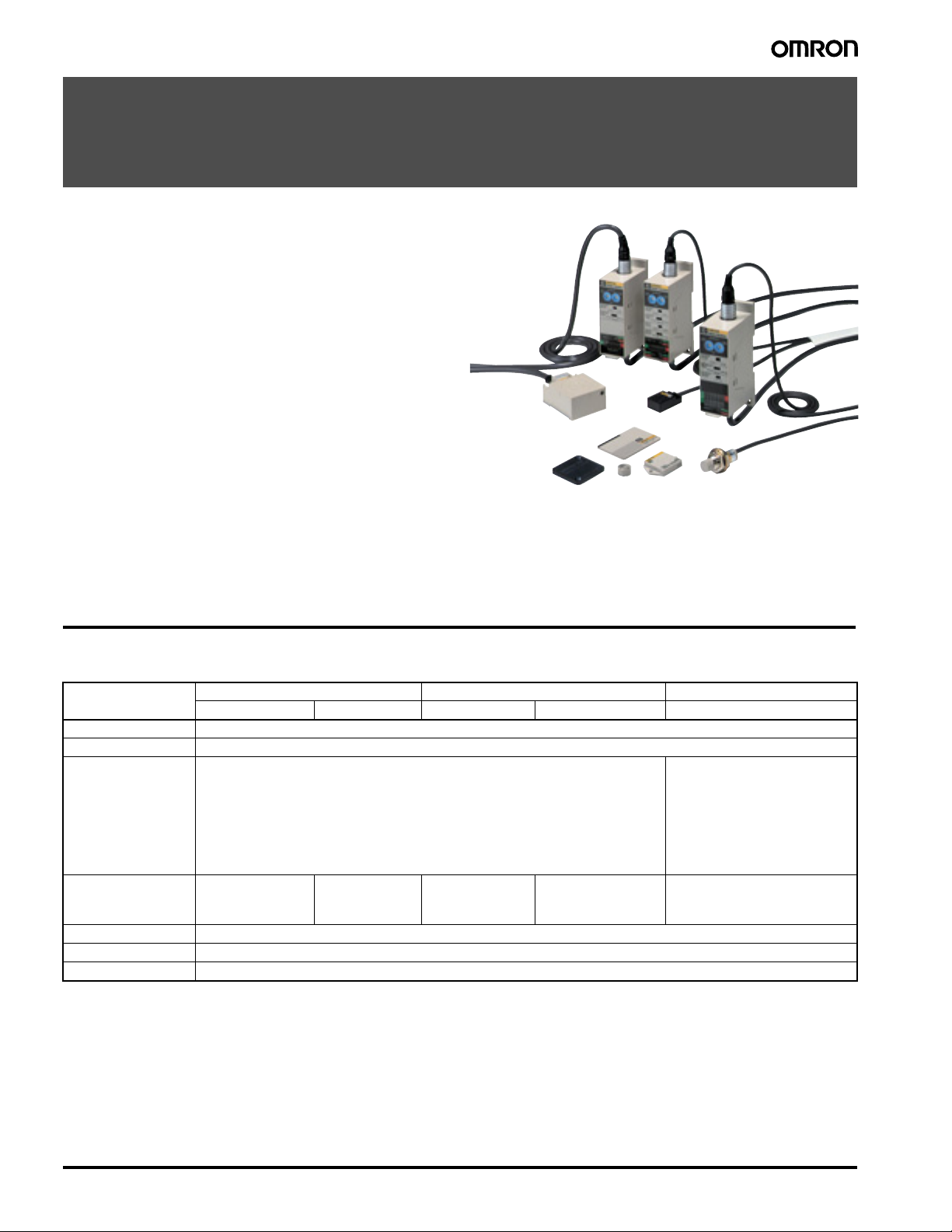
Intelligent Flag I/II
V600-HA
Innovative RFID Electronic Flags to
Replace Mechanical Flag and Kanban
Systems
• Doesn't need a program and can be used like a sensor.
• Advanced line construction at minimal cost.
• Saves space.
• Precise installation not required (Transmission distance:
100 mm max.).
• A verification function provided on multi-functional type.
• Addition of 16-bit models to the series responds to applications from Kanban to quality control.
• Equipped with a wiring reduction mode and communications
parity check function (16-bit models).
• Both NPN and PNP output available.
• FCC certified.
Ordering Information/Specifications
■ Amplifier
Type Read-only (8-bit) Multi-functional (8-bit) Read-only (16-bit)
Item Model V600-HAR91 V600-HAR81 V600-HAM91 V600-HAM81 V600-HAR92
Power supply 24 VDC ±10%, ripple (p-p): 10%
Current consumption 130 mA max.
Input Transistor output or contact output
Output
Diagnostic functions Checks for CPU errors and transmission errors
Insulation resistance 50 MΩ max. (at 500 VDC) between cable terminals and case
Dielectric strength 500 VAC, 50/60 Hz for 1 min between cable terminals and case (leakage current: 1 mA max.)
Short-circuit current: 3 mA (typical) (IN terminal and 0-V short-circuit)
OFF voltage: 15 to 30 VDC
ON voltage: 0 to 5 VDC
Input impedance: 8.2 kΩ
Applied voltage: 30 VDC max.
NPN open collector
output, 20 mA max. at
30 VDC, residual voltage: 2 V max.
PNP open collector
output, 20 mA max.
at 30 VDC, residual
voltage: 2 V max.
NPN open collector
output, 20 mA max. at
30 VDC, residual voltage: 2 V max.
PNP open collector output, 20 mA max. at 30
VDC, residual voltage: 2 V
max.
Transistor output
OFF voltage:
15 to 30 VDC
Input impedance:
8.2 kΩ
Short-circuit current:
3 mA (typical) (for 0-V short-circuit of
INHIBIT/TRG)
ON voltage:
0 to 5 VDC
Applied voltage:
30 VDC max.
NPN open collector output, 20 mA
max. at 30 VDC, residual voltage: 2 V
max.
2 Intelligent Flag I/II V600-HA
Page 2
Type Read-only (8-bit) Multi-functional (8-bit) Read-only (16-bit)
Item Model V600-HAR91 V600-HAR81 V600-HAM91 V600-HAM81 V600-HAR92
Vibration resistance Destruction: 10 to 150 Hz, 0.3-mm double amplitude, with 4 sweeps of 8 min each in
Shock resistance
Ambient temperature −10 to 55°C (with no icing)
Ambient humidity 35% to 85% (with no condensation)
Storage temperature −25 to 65°C
Degree of protection IEC60529: IP40
Ground Ground to 100 Ω or less.
Material ABS resin (case)
Cable length Standard, 0.5 m with a dedicated connector (See note.)
Weight Approx. 170 g Approx. 180 g
Note: The connector is not waterproof. If there is a possibility that the connector may be exposed to water, keep it inside the control box. Be sure
to use the connector together with the separately sold interface cable.
3 directions
Destruction: 294 m/s
2
, 3 times each in 6 directions
Destruction: 10 to 150 Hz, 1.5-mm
double amplitude, with 4 sweeps
of 8 min each in 3 directions
■ Functions
V600-HAR91/-HAR81 (Read-only type)
Reads the 8-bit data (1 byte) of the set address and outputs to the 8
data output lines.
V600-HAM91/-HAM81 (Multi-functional type)
The amplifier has the following three basic functions.
Read
Reads the 8-bit (1 byte) data of the set address and outputs to the 8
data output lines.
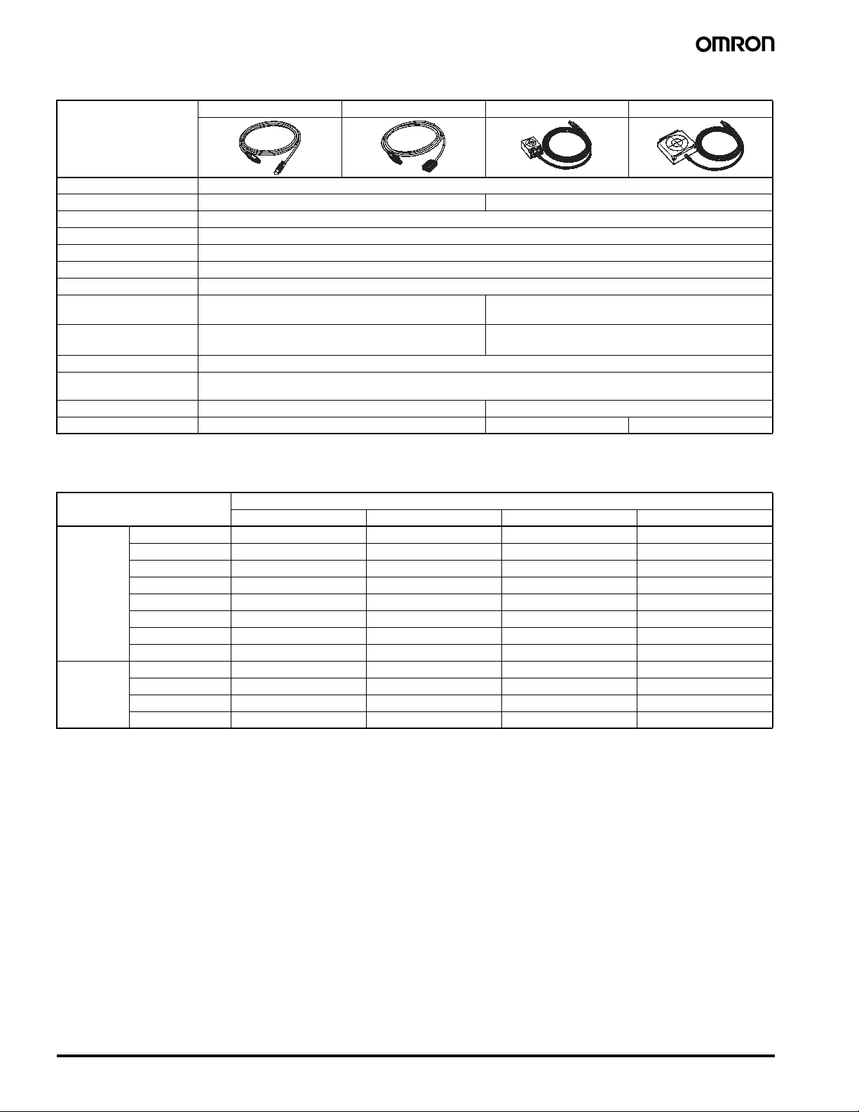
■ Interface Cable
Amplifier Cable length Interface Cable
V600-HAR91/81
(Connector: 20 pin)
V600-HAM91/81
V600-HAR92
(Connector: 26 pin)
Note: The interface cable connector is not waterproof. If there is a
possibility that the connector may be exposed to water, keep it
inside the control box. The maximum cable length is 10 m.
2 m V600-A60R
5 m V600-A61R
10 m V600-A62R
2 m V600-A60M
5 m V600-A61M
10 m V600-A62M
Write
Writes on the set address the 8-bit (1 byte) data designated via the 8
data input lines.
Verify
Reads the 8-bit data (1 byte) of the set address, compares with the 8bit (1 byte) data input via the 8 verification data input lines, and outputs the verification result.
V600-HAR92 (Read-only type)
Reads the 16-bit data (2 bytes) of the set address and outputs to the
16 data output lines.
Intelligent Flag I/II V600-HA 3
Page 3
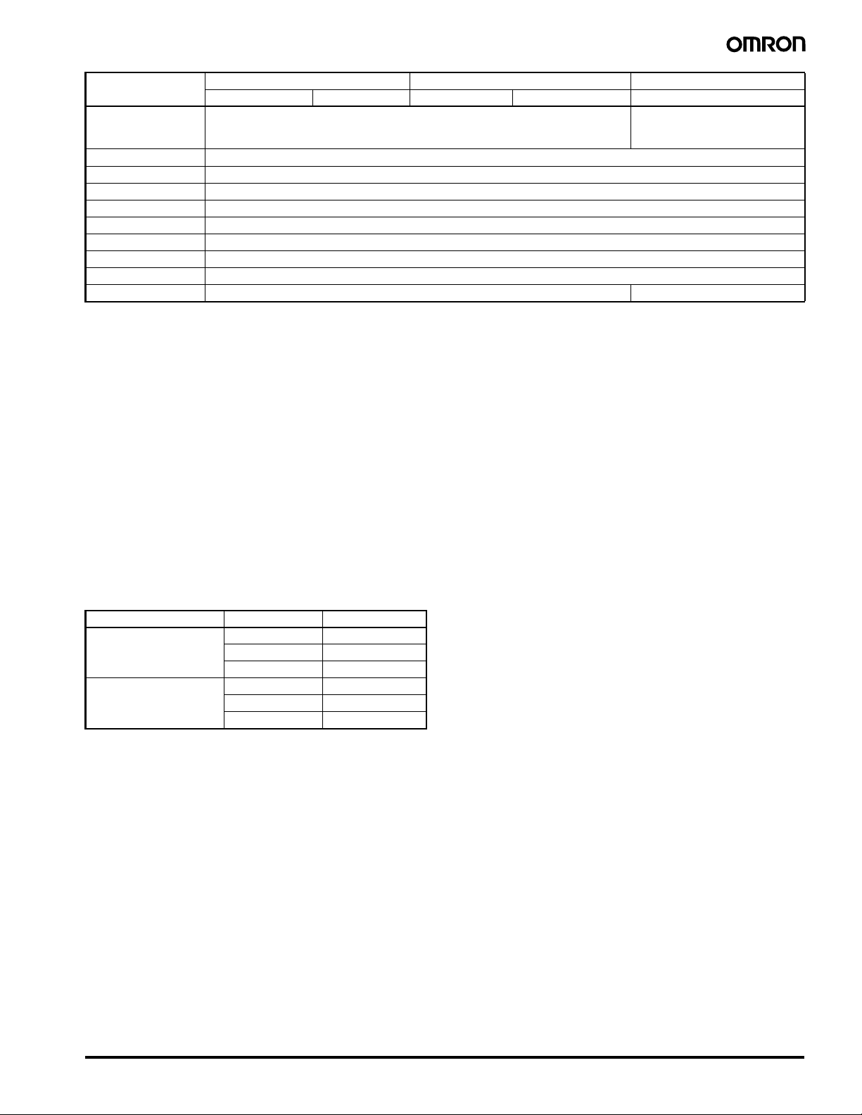
■ Sensor
Model V600-HS51 V600-HS61 V600-HS63 V600-HS67
Shape
Item
Transmission frequency 530 kHz
Ambient temperature −10 to 60°C −10 to 70°C
Storage temperature −25 to 75°C
Ambient humidity 35% to 95%
Insulation resistance 50 MΩ (at 500 VDC) between cable terminal and case
Dielectric strength 1,000 VAC, 50/60 Hz for 1 min between cable terminal and case (leakage current: 1 mA max.)
Degree of protection IEC60529: IP67
Vibration resistance Destruction: 10 to 2,000 Hz, 3-mm double amplitude, with
Shock resistance
Cable length 2 m (fixed)
Wireless transmission
error direction
Indicator --- Power: green
Weight Approx. 70 g Approx. 190 g Approx. 540 g
2 sweeps of 15 min each in 3 directions
2
Destruction: 981 m/s
times total)
16-bit CRC (Cyclic Redundancy Check) in both directions
, 3 times each in 3 directions (18
Destruction: 10 to 500 Hz, 2-mm double amplitude, with 3
sweeps of 11 min each in 3 directions
Destruction: 490 m/s2, 3 times each in 3 directions (18
times total)
■ Transmission Distance Specifications
Recommended Combinations
Amplifier V600-HAR91/-HAR81/-HAM91/-HAM81/-HAR92
Data Carrier
Memory
EEPROM
(Batteryless type)
Memory
SRAM
(Built-inbattery
type)
Note: 1. The specifications take fluctuations in ambient temperature and slight differences between products into account.
2. The read distance and write distance are the same.
3. Sensor Installation Conditions
• V600-HS51:When flush-mounted in iron
Axial offset from the Data Carrier: ±2.0 mm
4. Data Carrier Installation Conditions
5. The transmission distance specified in the specifications is also applicable when the Data Carrier is mounted on non-metallic surfaces.
6. The Data Carrier is stationary.
V600-D23P53 0.5 to 3.0 mm 0.5 to 3.0 mm --- --V600-D23P54 0.5 to 5.0 mm 0.5 to 5.5 mm --- --V600-D23P55 0.5 to 7.0 mm 0.5 to 7.0 mm 0.5 to 9.5 mm --V600-D23P61 0.5 to 8.0 mm 0.5 to 9.0 mm 2 to 16 mm --V600-D23P66N --- --- 5 to 30 mm 5 to 35 mm
V600-D23P66SP --- --- 5 to 25 mm 5 to 30 mm
V600-D23P71 --- --- 5 to 35 mm 10 to 70 mm
V600-D23P72 --- 0.5 to 18 mm 5 to 35 mm 10 to 50 mm
V600-D8KR12 5 to 15 mm 5 to 18 mm 5 to 45 mm 10 to 60 mm
V600-D8KR13 --- --- 10 to 30 mm 10 to 40 mm
V600-D8KR04 --- --- 10 to 65 mm 10 to 100 mm
V600-D2KR16 --- --- 2 to 15 mm ---
• V600-HS61: When surface-mounted on metal (ferrous)
• V600-HS63: When surface-mounted on metal (ferrous)
• V600-HS67: When surface-mounted on metal (ferrous)
• V600-D23P53/-P54: When flush-mounted in iron
• V600-D23P55/-P66N/-P66SP/-P71/-P72: When surface-mounted on resin (no metal on the backside)
• V600-D23P61: When surface-mounted on metal (ferrous)
• V600-D8KR12/-13/-04: When surface-mounted on metal (ferrous)
• V600-D2KR16: When the Data Carrier attached to the holder is mounted on a metal (ferrous) surface
Sensor V600-HS51 V600-HS61 V600-HS63 V600-HS67
Axial offset from the Data Carrier: ±2.0 mm
Axial offset from the Data Carrier: ±10.0 mm
Axial offset from the Data Carrier: ±10.0 mm
4 Intelligent Flag I/II V600-HA
Page 4
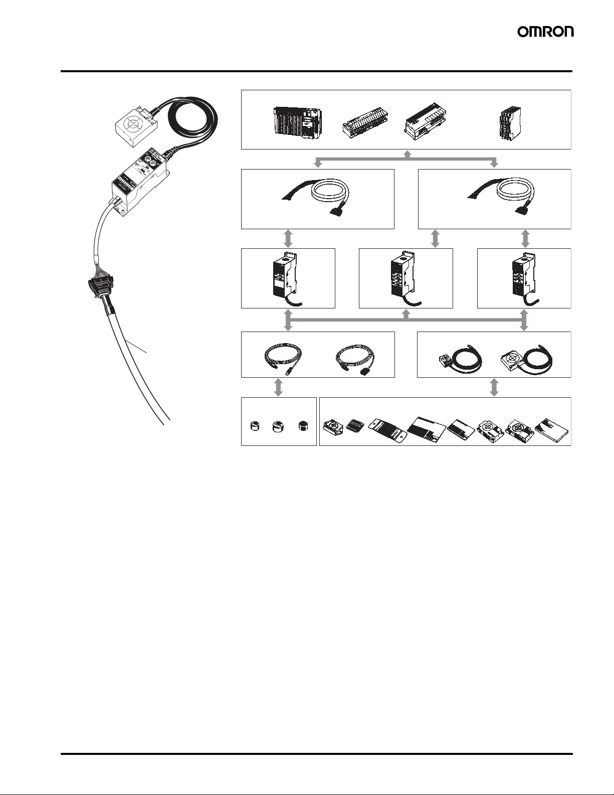
System Configuration
Sensor
(Cable length: fixed to 2 m)
Amplifier (Cable length:
fixed to 0.5 m, with connector)
interface
Interface cable available in
three lengths: 2 m,
5 m, and 10 m (10 m max.)
Connector
connection
Host
Programmable Controller, I/O terminal, B7A, CompoBus/S, etc. Sensor Controller
Terminal block wiring
Interface cable
V600-A6R V600-A6M
Connector pins: 20
Cable lengths: 2 m, 5 m,
10 m
Connector
Amplifier
Power
supply
24 VDC
Connector
connection
connection
V600
-HAR91/
HAR81
Sensor
V600-HS51 V600-HS61 V600-HS63 V600-HS67
Power
supply
24 VDC
Connector connection Connector connection
Connector pins: 26
Cable lengths: 2 m, 5 m,
10 m
Connector
connection
V600
-HAM91/
HAM81
Connector
connection
Power
supply
24 VDC
V600
-HAR92
V600
-D23P53
Wireless
transmission
V600
-D23P54
V600
-D23P55
V600
-D23P61
Data Carrier
V600
V600
-D23P66N
-D23P66SP
V600
-D23P71
V600
-D23P72
V600
-D8KR12
Wireless
transmission
V600
-D8KR04
V600
-D2KR16
Intelligent Flag I/II V600-HA 5
Page 5
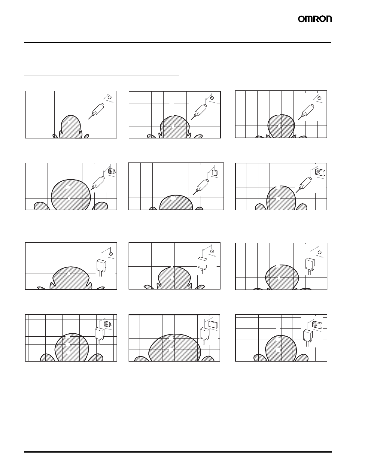
Characteristic Data (Typical)
■ Transmission Range
Combinations with the V600-HS51 Sensor
V600-HS51 & V600-D23P53 V600-HS51 & V600-D23P54 V600-HS51 & V600-D23P55
Y
8
4
Y
X
Y
12
8
4
Y
X
Y
15
10
5
Y
X
0–4–8 4 8
X
0–4–8–12 4
812
X
0–5–10–15 5
V600-HS51 & V600-D23P61 V600-HS51 & V600-D23P66N V600-HS51 & V600-D8KR12
Y
15
10
5
0–5–10–15 5 10 15
Y
X
X
Y
30
20
10
0–10–20–30 10
20 30
Y
X
X
Y
30
20
10
0–10–20–30 10 20 30
Combinations with the V600-HS61 Sensor
V600-HS61 & V600-D23P53 V600-HS61 & V600-D23P54 V600-HS61 & V600-D23P55
Y
8
4
0–4–8 4 8
Y
X
X
Y
12
8
4
0–4–8–12 4 8 12
Y
X
X
V600-HS61 & V600-D23P61 V600-HS61 & V600-D23P72 V600-HS61 & V600-D8KR12
Y
20
15
10
5
Y
X
Y
30
20
10
Y
X
Y
15
10
5
0–5–10–15 5
Y
30
20
10
10 15
Y
Y
10 15
Y
X
X
X
X
X
X
0–5–10–15–20–25 5 10 15 20 25
X
6 Intelligent Flag I/II V600-HA
0–10–20–30 10 20 30
X
0–10–20–30 10 20 30
X
Page 6

Combinations with the V600-HS63 Sensor
V600-HS63 & V600-D23P55 V600-HS63 & V600-D23P61 V600-HS63 & V600-D23P66N
Y
Y
30
X
20
10
Y
30
20
10
Y
X
Y
50
40
30
20
10
Y
X
20 30
X0–10–20–30 10
0–10–20–30–40 10 20 30 40
X
0–10–20–30–40–50 10 20 30 5040
V600-HS63 & V600-D23P66SP V600-HS63 & V600-D23P71 V600-HS63 & V600-D23P72
Y
50
40
30
20
10
0–10–20–30–40–50 10 20 30 5040
Y
X
X
Y
60
Y
X
40
20
X
0–20–40–60 20 40 60
X
Y
60
40
20
0–20–40–60 20 40 60
V600-HS63 & V600-D8KR12 V600-HS63 & V600-D8KR04 V600-HS63 & V600-D2KR16
Y
60
40
20
0–20–40–60 20 40 60
Y
X
Y
80
60
40
20
X
0–20–40–60–80 20 40 60 80
Y
X
Y
60
40
20
X
0–20–40–60–80 20 40 60 80
X
Y
X
X
Y
X
X
Intelligent Flag I/II V600-HA 7
Page 7

Combinations with the V600-HS67 Sensor
–
V600-HS67 & V600-D23P66N V600-HS67 & V600-D23P66SP V600-HS67 & V600-D23P71
Y
80
60
40
20
Y
X
Y
80
60
40
20
Y
XX
Y
100
80
60
40
20
Y
X
X020406080–20–40–60–80
0–20–40–60–80 20 40 60 80
X
0–20–40–60–80–100 20 40 60 80 100
V600-HS67 & V600-D23P72 V600-HS67 & V600-D8KR12 V600-HS67 & V600-D8KR13
Y
100
80
60
40
20
100 20 40 60 80 100
0–20–40–60–80
Y
X
Y
80
60
40
20
X
0–20–40–60–80 20406080
Y
X
X
Y
80
60
40
20
0–20–40–60–80 20406080
Y
X
V600-HS67 & V600-D8KR04
Y
120
80
40
0–40–80–120 40 80 120
Y
X
X
■ Transmission Time
The transmission time refers to the time required for communications between the Sensor and the Data Carrier. It is used for calculating the travel
speed of the auto command.
X
X
DC speed
(conveyor
speed)
Distance travelled in the transmission range
=
Transmission time
Model V600-HAR91/-HAR81/-HAM91/-HAM81 V600-HAR92
Read Write Read
Mode type DATA READ mode,
VERIFY READ mode
BYTE mode BIT SET mode, BIT
CLEAR mode
DATA READ mode
Data Carrier type EEPROM 75 ms 138 ms 150 ms 77 ms
SRAM 60 ms 95 ms 107 ms 62 ms
Example: Combinations with the V600-HAR91, V600-HS63, and V600-D8KR04 Sensors.
Y
80
60
DC speed
(conveyor
speed)
40
20
0–20–40–60–80 20 40 60 80
75 (mm)
=
60 (ms)
=
Y
75 × 10
60 × 10
X
X
-3
(m)
-3
× 1/60 (min)
= 75 (m/min)
Note: 1. The DC speed varies depending on transmission distance Y
and the axial offset. It is recommended that you refer to the
transmission range graphs and use the product where the
range is the largest.
2. This calculation is intended as a guideline only. Perform a
test with the actual product prior to use.
3. This equation does not include transmission error processing.
8 Intelligent Flag I/II V600-HA
Page 8

Circuit Configuration
T
g
V600-HAR91
V600-HAM91
Input Circuit
24 V
Ω
0 V
8.2 k
IN
ON/
OFF
Tr
Output Circuit
Main circuit
V600-HAR92
Input Circuit
24 V
Ω
ON/
OFF
Tr
Output Circuit
Main circuit
8.2 k
IN
0 V
Main circuit
OUT
0 V
Main circuit
OUT
V600-HAR81
V600-HAM81
Input Circuit
+DC
Tr
IN
8.2 kΩ
0 V
Output Circuit
Main circuit
Main circuit
+DC
OU
0 V
0 V
Precautions
■ Cautions
!Caution
Be sure to house the V600-HA@91/-HA@81/-HA@92 together with
their connectors and cable in control boxes when using them and
do not expose them to water, oil, dust, metal powder, corrosive
gas, or organic solvent, otherwise they may malfunction, suffer
damage, or burn.
!Caution
The connectors of the V600-HA@91/-HA@81/-HA@92 can be
mounted to metal plates, provided that there is an insulation plate
with a thickness of 1.5 mm minimum between each of the connectors and metal plates.
Input/Output
The Data Input and Data Output lines are set to “1" when the transistor turns ON and to “0" when it turns OFF.
Do not use a solid-state output with the following ratings with the
V600-HAM91/-HAM81, otherwise an external input error may result.
1. Maximum switching current: 1 A min.
2. Minimum switching current: 10 mA min.
3. Response time (ON to OFF): 3 ms min.
The following OMRON products cannot be connected to this product.
• CVM1-OD219, C20H, C28H, C40H, or C60H Programmable
Controllers
• Sensor Controllers other than from the S3D2 Series
When using a contact output, pay careful attention to chattering and
to the minimum switching current. Also note that the minimum switching current may be specified for some solid-state outputs.
When connecting an inductive load or an electrical device that tends
to generate noise to the output, connect a diode in parallel with the
load. Connect the cathode side of the diode to the positive side of the
power source.
L
Open collector output
Diode
Diode
Peak inverse voltage
Minimum of three times of the load voltage
e rectified current: 1 A
Avera
DC
power supply
Intelligent Flag I/II V600-HA 9
Page 9

Power Supply Voltage
Do not impose any voltage exceeding the rated voltage range. Doing
so, or applying alternating current (100 VAC) may cause the product
to explode or burn.
Load Short-circuiting
Do not short-circuit the load connected to the product or connect to
the power supply. Doing so may cause the product to explode or
burn.
Wiring
Avoid wiring mistakes such as incorrect polarity in the power supply.
Wiring mistakes may cause the product to explode or burn.
■ Correct Use
Grounding
The FG line is provided for grounding to the earth. When using the
Amplifier in an environment where it is exposed to large amounts of
noise or if the V600-HA@91/-HA@81/-HA@92 Amplifier malfunctions,
provide a Class-3 ground (ground resistance of 100 Ω or less). Note
that sharing the grounding wire with other equipment or grounding to
the beam of a building will adversely affect the grounding effect.
I/O Interface Requirements
1. The TRG input must be 10 ms min.
2. The INHIBIT input must be 20 ms min.
3. Minimum of 5 ms is required as the transfer time of the Read/
Write Selection Input (W/R).
4. The read data output must be read after the Normal End Output is
set to ON.
Connecting the Sensor
Hold the black part of the connector, line up the notch and push it in
until it clicks.
V600-HA91/81/92 Other equipment
OK
FG
V600-HA91/81/92 Other equipment
Less than 100 Ω
NG
FG
Less than 100
Ω
Mounting
Amplifier Spacing
When installing V600-HA@91/V600-HA@81/V600-HA@92 Amplifiers in a row, provide a minimum space of 10 mm between Amplifiers
in order to prevent them from being affected by the heat produced by
each Amplifier.
10 mm min.
Compatibility with the SRAM Memory
Type Data Carrier
1. If the Data Carrier is stationary in the transmission area for a long
time when using the V600-HA@91/81 in the AUTO mode, or when
using the V600-HAR92, it will drastically reduce the battery life.
Therefore, stop the oscillation in the sensor either by turning off
the power of the V600-HA@91/81/92 Amplifier or by setting the
Inhibit input to ON.
2. Use a Data Carrier that has the oscillation frequency of 530 kHz.
Note that the following models manufactured before February
1991 cannot be used.
• V600-D2KR01
• V600-D2KR02
Precautions When Using the AUTO
Mode
If transmitting to the Data Carrier while it is traveling under the AUTO
mode, conduct tests to make sure that the travel speed and installation conditions are fully satisfied.
V600-HA91/81/92
When housing the Amplifiers in a box, provide a fan or ventilation
opening for radiating the heat.
When wiring power cables, which carry large current such as motor
drive cables, near the V600-HA@91/81/92 Amplifiers, conduct necessary tests to make sure that the installation conditions are fully satisfied.
10 Intelligent Flag I/II V600-HA
Page 10

Dimensions
Note: All units are in millimeters unless otherwise indicated.
Amplifier
V600-HAR91/-HAR81
* Enlarged Section of Mounting Hole
25
4.4
30
Two, mounting
holes
*
89
98
Mounting Hole Dimensions
2-M4
89±0.2
21±0.2
17.5
5.5
28.3
30û
36.3
61.8
68.5
Vinyl-insulated round cord 5.8-mm dia.,
13-conductor cable, standard length: 0.5 m
XG4E-2031
55
6
80
44.7
35.2
500 mm
28.1
25
30
21
8.2
Intelligent Flag I/II V600-HA 11
Page 11

V600-HAM91/-HAM81
* Enlarged Section of Mounting Hole
4.4
25
30
Two mounting
holes *
89
98
Mounting Hole Dimensions
2-M4
89±0.2
21±0.2
17.5
5.5
28.3
30˚
36.3
44.3
52.3
61.8
68.5
75
Vinyl-insulated round cord 5.8-mm dia.,
23-conductor cable, standard length: 0.5 m
XG4E-2631
55
6
80
52.3
35.2
500 mm
28.1
25
30
21
8.2
12 Intelligent Flag I/II V600-HA
Page 12

V600-HAR92
* Enlarged Section of Mounting Hole
4.4
25
30
Two, mounting
holes *
89
98
Mounting Hole Dimensions
2-M4
89±0.2
21±0.2
17.5
5.5
28.3
30˚
36.3
44.3
61.8
68.5
75
80
Vinyl-insulated round cord 5.8-mm dia.,
23-conductor cable, standard length: 0.5 m
XG4E-2631
55
52.3
6
35.2
500 mm
28.1
25
30
21
8.2
Sensor
V600-HS51
V600-HS61
M12X1
9.6 dia.
18
Detection surface
10
2 lock washers
2 lock nuts
7
33
35
30.5
4.5
18
12±0.2
8.5
2-3.5X5
(mounting holes)
Vinyl-insulated round cord (4-mm dia.)
Connector
49.5
49.5
Connector
Vinyl-insulated round cord (4-mm dia.)
6.5
13.7 dia.
13.7 dia.
Case: Brass
Transmission window: ABS resin
Filter: Epoxy resin
Cable: PVC (oil-resistant)
Case: ABS resin
Filter: Epoxy resin
Cable: PVC (oil-resistant)
Intelligent Flag I/II V600-HA 13
Page 13

V600-HS63
40 28
4-R1
Two, 4.5-dia. mounting holes
2-R5
10
Bushing
Vinyl-insulated round cord 6-mm dia
(7/0.18-mm dia.), 8-conductor cable,
standard length: 2 m
Connector
13.8 dia.
V600-HS67
Power indicator (green)
Power indicator
(green)
5
5
23
11
5
5
50
100
0.2
±
90
14
27 6
50
90
100
2053
Case: ABS resin
Filter: Epoxy resin
Cable: PVC (oil-resistant)
Four, 4.5-dia.
0.2
±
mounting holes
25
Bushing
Vinyl-insulated round cord (6-mm dia.)
10
10
51.5
Connector
51.5
Case: ABS resin
Filter: Epoxy resin
Cable: PVC (oil-resistant)
135
18
13.8 dia.
Interface Cable
V600-A6@R (for V600-HAR91/-HAR81))
30
20
330
0
+5
±5
±5
20
20
+100
L
0
Vinyl-insulated round cord 9-mm dia
(7/0.2-mm dia.), 13-conductor cable,
standard length: 2 m
±5
20
11
10.6
±5
30
30
37.6
XG5M-2032-N Connector
7.6
14 Intelligent Flag I/II V600-HA
Page 14

V600-A6@M (for V600-HAM91/-HAM81/-HAR92)
330
0
Model L (m)
V600-A60R/60M 2
V600-A61R/61M 5
V600-A62R/62M 10
+5
±5
±5
20
20
Vinyl-insulated round cord 9-mm dia (7/0.2-mm dia.),
23-conductor cable, standard length: 2 m
L
0
+100
±5
±5
20
30
30
XG5M-2632-N Connector
10.6
7.6
37.6
Intelligent Flag I/II V600-HA 15
Page 15

Terms and Conditions
WARRANTY, LIMITATIONS OF
LIABILITY
WARRANTY OMRON’s exclusive warranty is that the products are
free from defects in materials and workmanship for a period of one
year (or other period if specified) from date of sale by OMRON.
OMRON MAKES NO WARRANTY OR REPRESENTATION,
EXPRESS OR IMPLIED, REGARDING NON-INFRINGEMENT,
MERCHANTABILITY OR FITNESS FOR PARTICULAR PURPOSE
OF THE PRODUCTS. ANY BUYER OR USER ACKNOWLEDGES
THAT IT ALONE HAS DETERMINED THAT THE PRODUCTS WILL
SUITABLY MEET THE REQUIREMENTS OF THEIR INTENDED
USE. OMRON DISCLAIMS ALL OTHER WARRANTIES, EXPRESS
OR IMPLIED.
LIMITATIONS OF LIABILITY
OMRON SHALL NOT BE RESPONSIBLE FOR SPECIAL, INDIRECT OR CONSEQUENTIAL DAMAGES,
LOSS OF PROFITS OR COMMERCIAL LOSS IN ANY WAY CONNECTED WITH THE PRODUCTS, WHETHER SUCH CLAIM IS
BASED ON CONTRACT, WARRANTY, NEGLIGENCE OR STRICT
LIABILITY.
In no event shall responsibility of OMRON for any act exceed the individual price of the product on which liability is asserted.
IN NO EVENT SHALL OMRON BE RESPONSIBLE FOR WARRANTY, REPAIR OR OTHER CLAIMS REGARDING THE PRODUCTS UNLESS OMRON’S ANALYSIS CONFIRMS THAT THE
PRODUCTS WERE PROPERLY HANDLED, STORED, INSTALLED
AND MAINTAINED AND NOT SUBJECT TO CONTAMINATION,
ABUSE, MISUSE, OR INAPPROPRIATE MODIFICATION OR
REPAIR.
APPLICATION CONSIDERATIONS
SUITABILITY FOR USE OMRON shall not be responsible for confor-
mity with any standards, codes or regulations which apply to the
combination of the product in the customer's application or use of the
product.
At the customer's request, OMRON will provide applicable third party
certification documents identifying ratings and limitations of use
which apply to the product. This information by itself is not sufficient
for a complete determination of the suitability of the product in combination with the end product, machine, system, or other application or
use.
The following are some examples of applications for which particular
attention must be given. This is not intended to be an exhaustive list
of all possible uses of this product, nor is it intended to imply that the
uses listed may be suitable for this product:
• Outdoor use, uses involving potential chemical contamination or
electrical interference, or conditions or uses not described in this
catalog.
• Nuclear energy control systems, combustion systems, railroad systems, aviation systems, medical equipment, amusement machines,
vehicles, safety equipment, and installations subject to separate
industry or government regulations.
• Systems, machines and equipment that could present a risk to life
or property.
Please know and observe all prohibitions of use applicable to this
product.
NEVER USE THE PRODUCT FOR AN APPLICATION INVOLVING
SERIOUS RISK TO LIFE OR PROPERTY WITHOUT ENSURING
THAT THE SYSTEM AS A WHOLE HAS BEEN DESIGNED TO
ADDRESS THE RISKS, AND THAT THE OMRON PRODUCT IS
PROPERLY RATED AND INSTALLED FOR THE INTENDED USE
WITHIN THE OVERALL EQUIPMENT OR SYSTEM.
PROGRAMMABLE PRODUCTS OMRON shall not be responsible
for the user’s programming of a programmable product, or any consequence thereof.
DISCLAIMERS
PERFORMANCE DATA Performance data given in this catalog is
provided as a guide for the user in determining suitability and does
not constitute a warranty. It may represent the result of OMRON’s
test conditions, and the user must correlate it to actual application
requirements. Actual performance is subject to the OMRON Warranty and Limitations of Liability.
CHANGE IN SPECIFICATIONS
Product specifications and accessories may be changed at any time based on improvements and other
reasons. It is our practice to change part numbers when published
ratings or features are changed, or when significant construction
changes are made. However, some specifications of the product may
be changed without any notice. When in doubt, special part numbers
may be assigned to fix or establish key specifications for your application. Please consult with your OMRON representative at any time
to confirm actual specifications of purchased product.
ERRORS AND OMISSIONS
The information in this catalog has
been carefully checked and is believed to be accurate; however, no
responsibility is assumed for clerical, typographical or proofreading
errors, or omissions.
OMRON ON-LINE
Global - http://www.omron.com
USA - http://www.omron.com/oei
Canada - http://www.omron.ca
ALL DIMENSIONS SHOWN ARE IN MILLIMETERS. To convert millimeters into inches, divide by 25.4
Cat. No. GC RFID 4
Printed in USA
OMRON CANADA, INC.
885 Milner Avenue
Toronto, Ontario M1B 5V8
416-286-6465
OMRON ELECTRONICS LLC
One Commerce Drive
Schaumburg, IL 60173
847-843-7900
For US technical support or other inquiries:
800-556-6766
5/03 Specifications subject to change without notice
Complete terms and conditions for product purchase and use are on Omron’s website at
www.omron.com/oei – under the “About Us” tab, in the Legal Matters section.
16 Intelligent Flag I/II V600-HA
 Loading...