

Omron TL-T2E1-E, TL-T2F2-E, TL-T2E2-E, TL-T2F1-E, TL-T2E1-M5-E Datasheet
...
D-61TL-T
TL-T
Standard (thin shape) Inductive Proximity Sensor
TL-T
• Thin shape for space saving surface mounting
• Direct side wall mounting for bracket-less installation
Ordering Information
DC 3-wire Models
DC 4-wire Models (NO + NC)
Model Number Legend
Example: TL-T2F1-E 2M Square housing (40x12x26 mm), Sn=2 mm, shielded, PNP-NO,
made by OMG, pre-wired PVC cable (3x0,25 mm²) 2 m
TL-T4MF1-M5-E Square housing (40x12x26 mm), Sn=4 mm, not shielded,
PNP-NO, M8 (3-pole) connector, made by OMG
1. Basic name
TL
2. Housing & shape material
Square plastic 40 x 12 x 26 mm
3. Sensing distance
2: 2mm
4: 4mm
4. Shield
Blank: Shielded
M: Non-shielded
5. Power source & output
E: NPN voltage output
F: PNP voltage output
6. Operation mode
1: Normally open (NO)
2: Normally closed (NC)
3: Antivalent (NO + NC)
7. Kind of connection
Blank: Pre-wired, PVC dia 4mm
WA: Pre-wired, PUR/PVC dia 4mm
WR: Robot cable, PVC dia 4mm
M5: M8 connector (3-pole)
M1J: M12 connector (4-pole)
with pig-tail cable (PVC)
M3J: M8 connector (4-pole)
with pig-tail cable (PVC)
M5J: M8 connector (3-pole)
with pig-tail cable (PVC)
8. Production site
E: European Union
9. Cable length
Blank: Connector type
Numeral: Cable type
Installation Sensing distance Connection Output configuration Operation mode NO Operation mode NC
Shielded 2.0 mm Pre-wired NPN TL-T2E1-E TL-T2E2-E
PNP TL-T2F1-E TL-T2F2-E
M8 Connector (3-pin) NPN TL-T2E1-M5-E TL-T2E2-M5-E
PNP TL-T2F1-M5-E TL-T2F2-M5-E
Non-Shielded 4.0 mm Pre-wired NPN TL-T4ME1-E TL-T4ME2-E
PNP TL-T4MF1-E TL-T4MF2-E
M8 Connector (3-pin) NPN TL-T4ME1-M5-E TL-T4ME2-M5-E
PNP TL-T4MF1-M5-E TL-T4MF2-M5-E
Installation Sensing distance Connection Output configuration Operation mode antivalent (NO + NC)
Shielded 2.0 mm Pre-wired NPN TL-T2E3-E
PNP TL-T2F3-E
Non-Shielded 4.0 mm Pre-wired NPN TL-T4ME3-E
PNP TL-T4MF3-E
TL
-T
@ @ @ @ - @@ - @ @
1 2 3 5 7 8 9 46
D-62 Inductive Sensors
Specifications
DC 3-wire and DC 4-wire Models
Note: 1. The response frequency is an average value. Measurement conditions are as follows: standard target, a distance of twice the standard target distance between
targets, and a setting distance of half the sensing distance
2. PUR Cable and other legth request
Type
Item
Shielded Non-shielded
TL-T2E1-@@-E
TL-T2F1-@@-E
TL-T2E2-@@-E
TL-T2F2-@@-E
TL-T2E3-E
TL-T2F3-E
TL-T4ME1-@@-E
TL-T4MF1-@@-E
TL-T4ME2-@@-E
TL-T4MF2-@@-E
TL-T4ME3-E
TL-T4MF3-E
Sensing distance
2 mm ±10% 4 mm ±10%
Setting distance
0 to 1.6 mm 0 to 3.2 mm
Differential travel
15% max. of sensing distance
Target
Ferrous metal (The sensing distance decreases with non-ferrous metal)
Standard target
12 x 12 x 1 mm 12 x 12 x 1 mm
Response frequency (See note 1.)
3000 Hz
1500 Hz
Rated power supply voltage
(operating voltage range)
24 VDC. Ripple (p-p): 10% max.
(10 to 35 VDC)
Current consumption
DC 3-wire: ≤15 mA at 24 VDC
DC 4-wire: ≤15 mA at 24 VDC
Output type
TL-T@@E models: NPN voltage output
TL-T@@F models: NPN voltage output
Control output
Load current
300 mA max. each output
Residual voltage
≤2.0 VDC
Leakage current
DC 3-wire: <0,5 mA
DC 4-wire: <1 mA each output
Indicator
Output indicator (Yellow LED)
Operation mode
(with sensing object approaching)
TL-T@@E1/F1 models: NO
TL-T@@E2/F2 models: NC
TL-T@@E3/F3 models: NO + NC
For details, refer to Timing Charts.
Protection circuits
Output reverse polarity protection, Power source circuit reverse polarity protection, Surge suppressor,
Short-circuit protection
Ambient air temperature
Operating/Storage: –25° C to 70° C
Temperature influence
≤±10% max. of Sn at 23°C in temperature range of –25° C to 70° C
Humidity
35% to 95% RH
Voltage influence
±1% max. of sensing distance in the rated voltage range ±15%
Insulation resistance
>10 MΩ between current-carrying parts and case
Dielectric strength
1000 VAC at 50/60 Hz between current-carrying parts and case
Vibration resistance
0 to 55 Hz with 30 min. dwell time at resonance frequency or 55 Hz each in X, Y, and Z directions
55 to 2000 Hz, 150 m/s
2
, double amplitude for 2 hours each in X, Y, and Z directions
Shock resistance
300 m/s2 6 times each in X, Y, and Z directions
Degree of protection
in accordance with IEC 60529:
Pre-wired models: IP67
M8 connector models: IP65
Product standard
EN60947-5-2
Connection method
Pre-wired (See
note 2)
2m cable, 3x 0,25 mm2 for DC 3-wire models
4x 0,25 mm
2
for DC 4-wire models
Connector
M8 connector
Weight
(packaged)
Pre-wired model
Approx. 70 g
M8 connector
models
Approx. 20 g
Material
Case
PBT
Cable
PVC
D-63TL-T
TL-T
Engineering Data
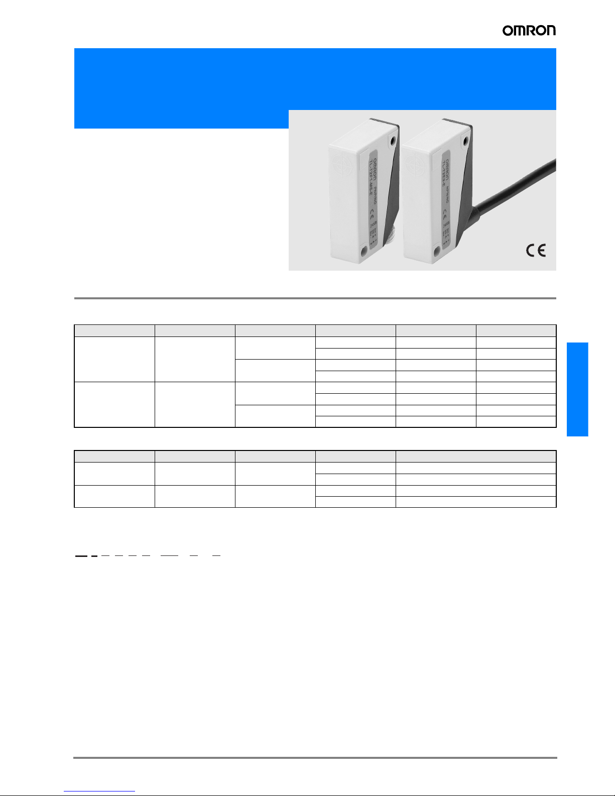
Operating Range (Typical)
Shielded and non-shielded models
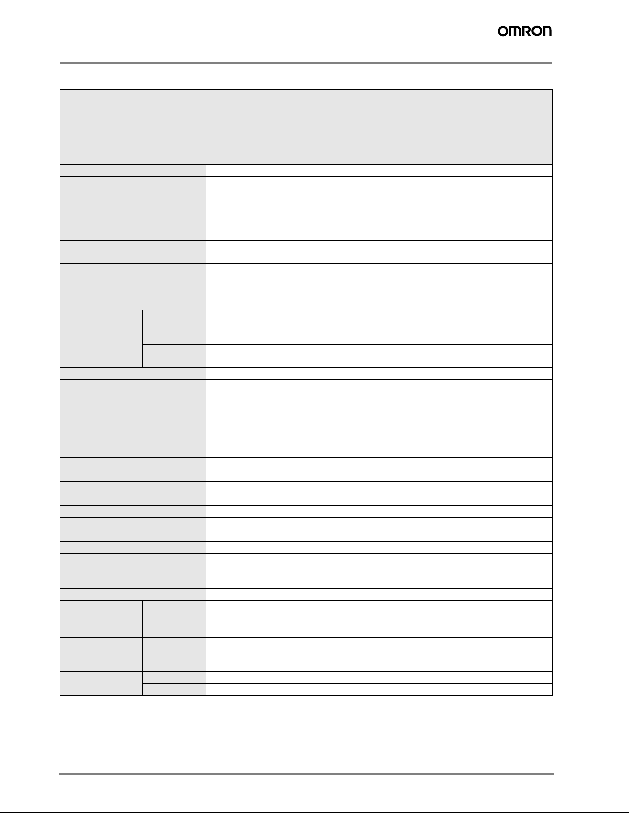
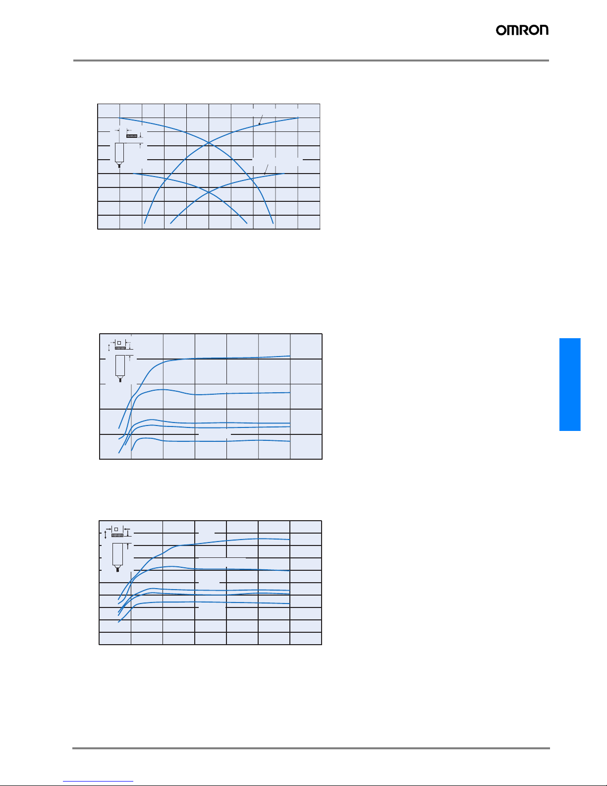
Influence of Sensing Object Size and Material
Shielded models
Non-shielded models
0,0
0,5
1,0
1,5
2,0
2,5
3,0
3,5
4,0
4,5
-5,0 -4,0 -3,0 -2,0 -1,0 0,0 1,0 2,0 3,0 4,0 5,0
Distance Y (mm)
Sensing distance X (mm)
X
Y
TL-T2 @@-@@-@
TL-T4M
@@- @@
-
@
0,0
0,5
1,0
1,5
2,0
2,5
0 5 10 15 20 25 30 35
Side length of sensing object d (mm)
Sensing distance x (mm)
Iron
Stainless steel
Brass
Aluminum
Copper
X
d
TL-T2@@ -@@ -@
0,0
0,5
1,0
1,5
2,0
2,5
3,0
3,5
4,0
4,5
5,0
0 5 10 15 20 25 30 35
Side length of sensing object d (mm)
Sensing distance x (mm)
X
d
Iron
Stainless steel
Brass
Aluminum
Copper
 Loading...