

Omron TL-T DATASHEET
Standard (thin shape) Inductive Proximity Sensor
TL-T
• Thin shape for space saving surface mounting
• Direct side wall mounting for bracket-less installation
Ordering Information
DC 3-wire Models
Installation Sensing distance Connection Output configuration Operation mode NO Operation mode NC
Shielded 2.0 mm Pre-wired NPN TL-T2E1-E TL-T2E2-E
PNP TL-T2F1-E TL-T2F2-E
M8 Connector (3-pin) NPN TL-T2E1-M5-E TL-T2E2-M5-E
PNP TL-T2F1-M5-E TL-T2F2-M5-E
Non-Shielded 4.0 mm Pre-wired NPN TL-T4ME1-E TL-T4ME2-E
PNP TL-T4MF1-E TL-T4MF2-E
M8 Connector (3-pin) NPN TL-T4ME1-M5-E TL-T4ME2-M5-E
PNP TL-T4MF1-M5-E TL-T4MF2-M5-E
TL-T
DC 4-wire Models (NO + NC)
Installation Sensing distance Connection Output configuration Operation mode antivalent (NO + NC)
Shielded 2.0 mm Pre-wired NPN TL-T2E3-E
PNP TL-T2F3-E
Non-Shielded 4.0 mm Pre-wired NPN TL-T4ME3-E
PNP TL-T4MF3-E
Model Number Legend
-T
@ @ @ @ - @@ - @ @
TL
1 2 3 5 7 8 9 46
1. Basic name
TL
2. Housing & shape material
Square plastic 40 x 12 x 26 mm
3. Sensing distance
2: 2mm
4: 4mm
4. Shield
Blank: Shielded
M: Non-shielded
5. Power source & output
E: NPN voltage output
F: PNP voltage output
6. Operation mode
1: Normally open (NO)
2: Normally closed (NC)
3: Antivalent (NO + NC)
Example: TL-T2F1-E 2M Square housing (40x12x26 mm), Sn=2 mm, shielded, PNP-NO,
made by OMG, pre-wired PVC cable (3x0,25 mm²) 2 m
TL-T4MF1-M5-E Square housing (40x12x26 mm), Sn=4 mm, not shielded,
PNP-NO, M8 (3-pole) connector, made by OMG
7. Kind of connection
Blank: Pre-wired, PVC dia 4mm
WA: Pre-wired, PUR/PVC dia 4mm
WR: Robot cable, PVC dia 4mm
M5: M8 connector (3-pole)
M1J: M12 connector (4-pole)
with pig-tail cable (PVC)
M3J: M8 connector (4-pole)
with pig-tail cable (PVC)
M5J: M8 connector (3-pole)
with pig-tail cable (PVC)
8. Production site
E: European Union
9. Cable length
Blank: Connector type
Numeral: Cable type
D-61TL-T
Specifications
DC 3-wire and DC 4-wire Models
Type
Item
Sensing distance
Setting distance
Differential travel
Target
Standard target
Response frequency (See note 1.)
Rated power supply voltage
(operating voltage range)
Current consumption
Output type
Load current
Residual volt-
Control output
age
Leakage current
Indicator
Operation mode
(with sensing object approaching)
Protection circuits
Ambient air temperature
Temperature influence
Humidity
Voltage influence
Insulation resistance
Dielectric strength
Vibration resistance
Shock resistance
Degree of protection
Product standard
Pre-wired (See
Connection method
note 2)
Connector
Weight
(packaged)
Material
Pre-wired model
M8 connector
models
Case
Cable
Shielded Non-shielded
TL-T2E1-@@-E
TL-T2F1-@@-E
TL-T2E2-@@-E
TL-T2F2-@@-E
TL-T2E3-E
TL-T2F3-E
2 mm ±10% 4 mm ±10%
0 to 1.6 mm 0 to 3.2 mm
15% max. of sensing distance
Ferrous metal (The sensing distance decreases with non-ferrous metal)
12 x 12 x 1 mm 12 x 12 x 1 mm
3000 Hz
24 VDC. Ripple (p-p): 10% max.
(10 to 35 VDC)
DC 3-wire: ≤15 mA at 24 VDC
DC 4-wire: ≤15 mA at 24 VDC
TL-T@@E models: NPN voltage output
TL-T@@F models: NPN voltage output
300 mA max. each output
≤2.0 VDC
DC 3-wire: <0,5 mA
DC 4-wire: <1 mA each output
Output indicator (Yellow LED)
TL-T@@E1/F1 models: NO
TL-T@@E2/F2 models: NC
TL-T@@E3/F3 models: NO + NC
For details, refer to Timing Charts.
Output reverse polarity protection, Power source circuit reverse polarity protection, Surge suppressor,
Short-circuit protection
Operating/Storage: –25° C to 70° C
≤±10% max. of Sn at 23°C in temperature range of –25° C to 70° C
35% to 95% RH
±1% max. of sensing distance in the rated voltage range ±15%
>10 MΩ between current-carrying parts and case
1000 VAC at 50/60 Hz between current-carrying parts and case
0 to 55 Hz with 30 min. dwell time at resonance frequency or 55 Hz each in X, Y, and Z directions
55 to 2000 Hz, 150 m/s
300 m/s2 6 times each in X, Y, and Z directions
in accordance with IEC 60529:
Pre-wired models: IP67
M8 connector models: IP65
EN60947-5-2
2m cable, 3x 0,25 mm2 for DC 3-wire models
4x 0,25 mm
M8 connector
Approx. 70 g
Approx. 20 g
PBT
PVC
2
, double amplitude for 2 hours each in X, Y, and Z directions
2
for DC 4-wire models
TL-T4ME1-@@-E
TL-T4MF1-@@-E
TL-T4ME2-@@-E
TL-T4MF2-@@-E
TL-T4ME3-E
TL-T4MF3-E
1500 Hz
Note: 1. The response frequency is an average value. Measurement conditions are as follows: standard target, a distance of twice the standard target distance between
targets, and a setting distance of half the sensing distance
2. PUR Cable and other legth request
D-62 Inductive Sensors
Engineering Data
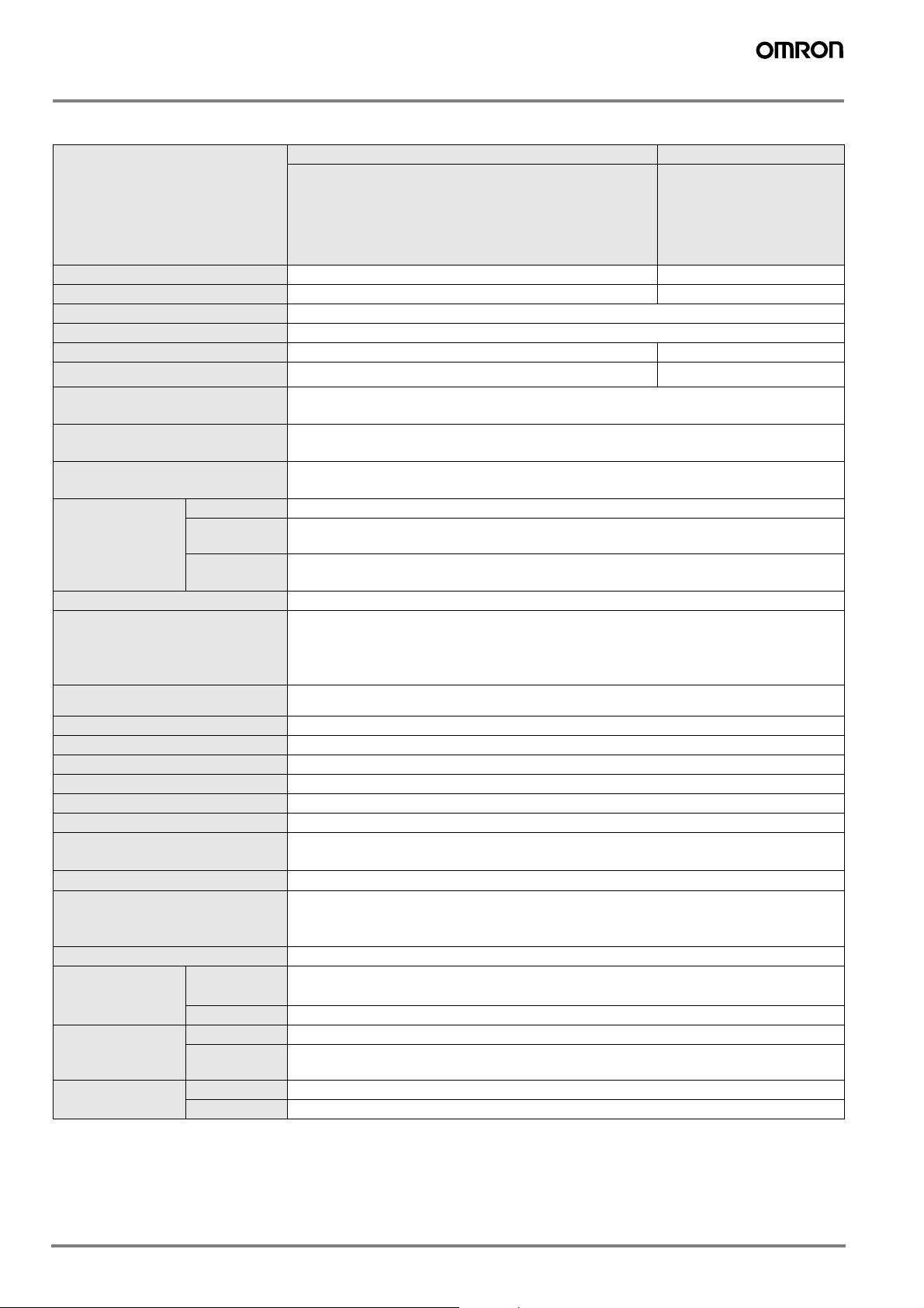
Operating Range (Typical)
Shielded and non-shielded models
4,5
4,0
3,5
3,0
2,5
2,0
Sensing distance X (mm)
1,5
1,0
0,5
0,0
-5,0 -4,0 -3,0 -2,0 -1,0 0,0 1,0 2,0 3,0 4,0 5,0
Y
X
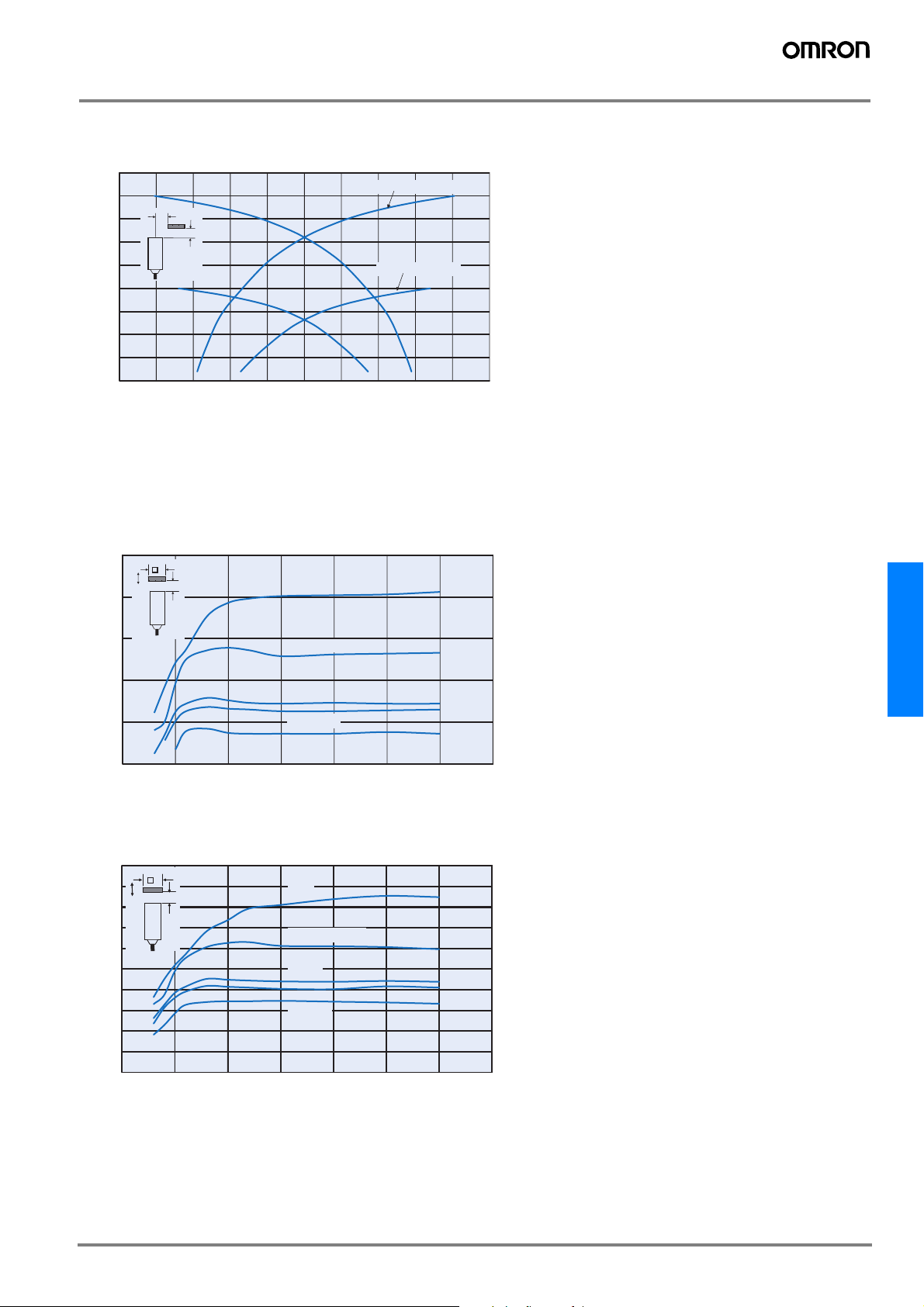
Influence of Sensing Object Size and Material
Shielded models
TL-T4M
@@- @@
TL-T2 @@-@@-@
Distance Y (mm)
-
@
TL-T2@@ -@@ -@
2,5
2,0
1,5
Sensing distance x (mm)
1,0
0,5
0,0
0 5 10 15 20 25 30 35
d
X
Iron
Stainless steel
Brass
Aluminum
Copper
Side length of sensing object d (mm)
Non-shielded models
5,0
4,5
4,0
3,5
3,0
2,5
Sensing distance x (mm)
2,0
1,5
1,0
0,5
0,0
d
X
0 5 10 15 20 25 30 35
Iron
Stainless steel
Brass
Aluminum
Copper
Side length of sensing object d (mm)
TL-T
D-63TL-T
 Loading...