

Page 1
Cat. No. I528-E1-05
USER’S MANUAL
SYSDRIVE 3G3JV
Compact Simplified Inverters
Page 2

Thank you for choosing this SYSDRIVE 3G3JV-series product. Proper use
and handling of the product will ensure proper product performance, will
lengthen product life, and may prevent possible accidents.
Please read this manual thoroughly and handle and operate the product
with care.
1. To ensure safe and proper use of the OMRON Inverters, please read this USER’S
MANUAL (Cat. No. I528-E1) to gain sufficient knowledge of the devices, safety information, and precautions before actual use.
2. The products are illustrated without covers and shieldings for closer look in this
USER’S MANUAL. For actual use of the products, make sure to use the covers and
shieldings as specified.
3. This USER’S MANUAL and other related user’s manuals are to be delivered to the
actual end users of the products.
4. Please keep this manual close at hand for future reference.
5. If the product has been left unused for a long time, please inquire at our sales representative.
NOTICE
1. This manual describes the functions of the product and relations with other
products. You should assume that anything not described in this manual is
not possible.
2. Although care has been given in documenting the product, please contact your
OMRON representative if you have any suggestions on improving this manual.
3. The product contains potentially dangerous parts under the cover. Do not attempt
to open the cover under any circumstances. Doing so may result in injury or death
and may damage the product. Never attempt to repair or disassemble the product.
4. We recommend that you add the following precautions to any instruction manuals
you prepare for the system into which the product is being installed.
S Precautions on the dangers of high-voltage equipment.
S Precautions on touching the terminals of the product even after power has been
turned OFF. (These terminals are live even with the power turned OFF.)
5. Specifications and functions may be changed without notice in order to improve
product performance.
Items to Check Before Unpacking
Check the following items before removing the product from the package:
S Has the correct product been delivered (i.e., the correct model number and speci-
fications)?
S Has the product been damaged in shipping?
S Are any screws or bolts loose?
Page 3
USER’S MANUAL
SYSDRIVE 3G3JV SERIES
Compact Simplified Inverter
Page 4

Notice:
OMRON products are manufactured for use according to proper procedures by a qualified
operator and only for the purposes described in this manual.
The following conventions are used to indicate and classify precautions in this manual. Always heed the information provided with them. Failure to heed precautions can result in injury to people or damage to property.
!
DANGER Indicates an imminently hazardous situation which, if not avoided, will result in death
or serious injury. Additionally, there may be severe property damage.
WARNING Indicates a potentially hazardous situation which, if not avoided, could result in death
!
or serious injury. Additionally, there may be severe property damage.
Caution Indicates a potentially hazardous situation which, if not avoided, may result in minor
!
or moderate injury, or property damage.
OMRON Product References
All OMRON products are capitalized in this manual. The word “Unit” is also capitalized when
it refers to an OMRON product, regardless of whether or not it appears in the proper name
of the product.
The abbreviation “Ch,” which appears in some displays and on some OMRON products,
often means “word” and is abbreviated “Wd” in documentation in this sense.
The abbreviation “PC” means Programmable Controller and is not used as an abbreviation
for anything else.
Visual Aids
The following headings appear in the left column of the manual to help you locate different
types of information.
Note Indicates information of particular interest for efficient and convenient operation of the product.
OMRON, 1999
All rights reserved. No part of this publication may be reproduced, stored in a retrieval system, or transmitted,
in any form, or by any means, mechanical, electronic, photocopying, recording, or otherwise, without the prior
written permission of OMRON.
No patent liability is assumed with respect to the use of the information contained herein. Moreover, because
OMRON is constantly striving to improve its high-quality products, the information contained in this manual
is subject to change without notice. Every precaution has been taken in the preparation of this manual. Nevertheless, OMRON assumes no responsibility for errors or omissions. Neither is any liability assumed for damages resulting from the use of the information contained in this publication.
Page 5

General Precautions
Observe the following precautions when using the SYSDRIVE Inverters and peripheral devices.
This manual may include illustrations of the product with protective covers removed in order
to describe the components of the product in detail. Make sure that these protective covers
are on the product before use.
Consult your OMRON representative when using the product after a long period of storage.
WARNING Do not touch the inside of the Inverter. Doing so may result in electrical shock.
!
WARNING Operation, maintenance, or inspection must be performed after turning OFF the
!
power supply, confirming that the CHARGE indicator (or status indicators) are OFF,
and after waiting for the time specified on the front cover. Not doing so may result in
electrical shock.
WARNING Do not damage, pull on, apply stress to, place heavy objects on, or pinch the cables.
!
Doing so may result in electrical shock.
WARNING Do not touch the rotating parts of the motor under operation. Doing so may result in
!
injury.
WARNING Do not modify the product. Doing so may result in injury or damage to the product.
!
Caution Do not store, install, or operate the product in the following places. Doing so may
!
result in electrical shock, fire or damage to the product.
S Locations subject to direct sunlight.
S Locations subject to temperatures or humidity outside the range specified in the
specifications.
S Locations subject to condensation as the result of severe changes in temperature.
S Locations subject to corrosive or flammable gases.
S Locations subject to exposure to combustibles.
S Locations subject to dust (especially iron dust) or salts.
S Locations subject to exposure to water, oil, or chemicals.
S Locations subject to shock or vibration.
Caution Do not touch the Inverter radiator, regenerative resistor, or Servomotor while the
!
power is being supplied or soon after the power is turned OFF. Doing so may result in
a skin burn due to the hot surface.
Caution Do not conduct a dielectric strength test on any part of the Inverter. Doing so may
!
result in damage to the product or malfunction.
Caution Take appropriate and sufficient countermeasures when installing systems in the fol-
!
lowing locations. Not doing so may result in equipment damage.
S Locations subject to static electricity or other forms of noise.
S Locations subject to strong electromagnetic fields and magnetic fields.
S Locations subject to possible exposure to radioactivity.
S Locations close to power supplies.
Page 6

Transportation Precautions
Caution Do not hold by front cover or panel, instead, hold by the radiation fin (heat sink) while
!
transporting the product. Doing so may result in injury.
Caution Do not pull on the cables. Doing so may result in damage to the product or malfunc-
!
tion.
Caution Use the eye-bolts only for transporting the Inverter. Using them for transporting the
!
machinery may result in injury or malfunction.
Installation Precautions
WARNING Provide an appropriate stopping device on the machine side to secure safety. (A
!
holding brake is not a stopping device for securing safety.) Not doing so may result in
injury.
WARNING Provide an external emergency stopping device that allows an instantaneous stop of
!
operation and power interruption. Not doing so may result in injury.
Caution Be sure to install the product in the correct direction and provide specified clear-
!
ances between the Inverter and control panel or with other devices. Not doing so
may result in fire or malfunction.
Caution Do not allow foreign objects to enter inside the product. Doing so may result in fire or
!
malfunction.
Caution Do not apply any strong impact. Doing so may result in damage to the product or
!
malfunction.
Wiring Precautions
WARNING Wiring must be performed only after confirming that the power supply has been
!
turned OFF. Not doing so may result in electrical shock.
WARNING Wiring must be performed by authorized personnel. Not doing so may result in
!
electrical shock or fire.
WARNING Be sure to confirm operation only after wiring the emergency stop circuit. Not doing
!
so may result in injury.
WARNING Always connect the ground terminals to a ground of 100 Ω or less for the 200-V AC
!
class, or 10 Ω or less for the 400-V AC class. Not connecting to a proper ground may
result in electrical shock.
Page 7

Caution Install external breakers and take other safety measures against short-circuiting in
!
external wiring. Not doing so may result in fire.
Caution Confirm that the rated input voltage of the Inverter is the same as the AC power sup-
!
ply voltage. An incorrect power supply may result in fire, injury, or malfunction.
Caution Connect the Braking Resistor and Braking Resistor Unit as specified in the manual.
!
Not doing so may result in fire.
Caution Be sure to wire correctly and securely. Not doing so may result in injury or damage to
!
the product.
Caution Be sure to firmly tighten the screws on the terminal block. Not doing so may result in
!
fire, injury, or damage to the product.
Caution Do not connect an AC power to the U, V, or W output. Doing so may result in damage
!
to the product or malfunction.
Operation and Adjustment Precautions
WARNING Turn ON the input power supply only after mounting the front cover, terminal covers,
!
bottom cover, Operator, and optional items. Not doing so may result in electrical
shock.
WARNING Do not remove the front cover, terminal covers, bottom cover, Operator, or optional
!
items while the power is being supplied. Doing so may result in electrical shock or
damage to the product.
WARNING Do not operate the Operator or switches with wet hands. Doing so may result in
!
electrical shock.
WARNING Do not touch the inside of the Inverter. Doing so may result in electrical shock.
!
WARNING Do not come close to the machine when using the error retry function because the
!
machine may abruptly start when stopped by an alarm. Doing so may result in injury.
WARNING Do not come close to the machine immediately after resetting momentary power
!
interruption to avoid an unexpected restart (if operation is set to be continued in the
processing selection function after momentary power interruption is reset). Doing so
may result in injury.
WARNING Provide a separate emergency stop switch because the STOP Key on the Operator
!
is valid only when function settings are performed. Not doing so may result in injury.
Page 8

WARNING Be sure to confirm that the RUN signal is turned OFF before turning ON the power
!
supply, resetting the alarm, or switching the LOCAL/REMOTE selector. Doing so
while the RUN signal is turned ON may result in injury.
Caution Be sure to confirm permissible ranges of motors and machines before operation be-
!
cause the Inverter speed can be easily changed from low to high. Not doing so may
result in damage to the product.
Caution Provide a separate holding brake when necessary. Not doing so may result in injury.
!
Caution Do not perform a signal check during operation. Doing so may result in injury or dam-
!
age to the product.
Caution Do not carelessly change settings. Doing so may result in injury or damage to the
!
product.
Maintenance and Inspection Precautions
WARNING Do not touch the Inverter terminals while the power is being supplied.
!
WARNING Maintenance or inspection must be performed only after turning OFF the power
!
supply, confirming that the CHARGE indicator (or status indicators) is turned OFF,
and after waiting for the time specified on the front cover. Not doing so may result in
electrical shock.
WARNING Maintenance, inspection, or parts replacement must be performed by authorized
!
personnel. Not doing so may result in electrical shock or injury.
WARNING Do not attempt to take the Unit apart or repair. Doing either of these may result in
!
electrical shock or injury.
Caution Carefully handle the Inverter because it uses semiconductor elements. Careless
!
handling may result in malfunction.
Caution Do not change wiring, disconnect connectors, the Operator, or optional items, or re-
!
place fans while power is being supplied. Doing so may result in injury, damage to
the product, or malfunction.
Page 9
Warning Labels
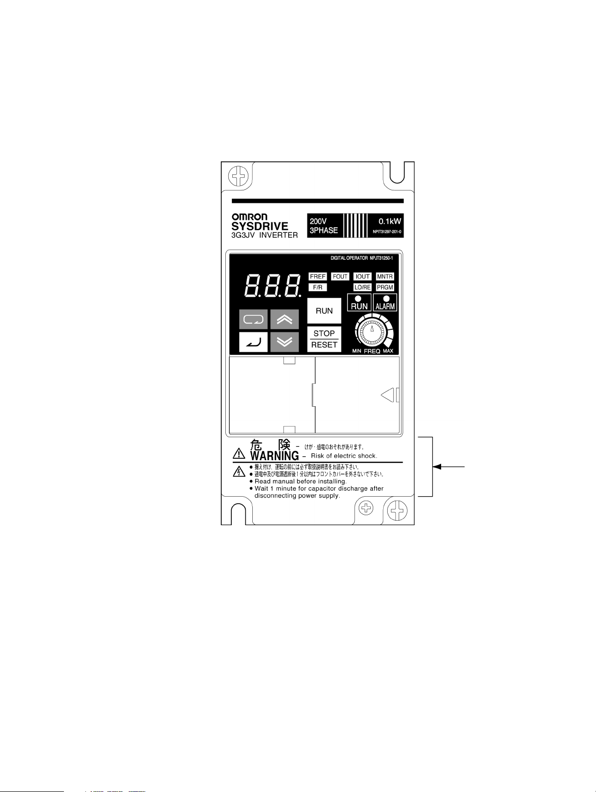
Warning labels are pasted on the product as shown in the following illustration. Be sure to
follow the instructions given there.
H Warning Labels
Warning label
Page 10
H Contents of Warning
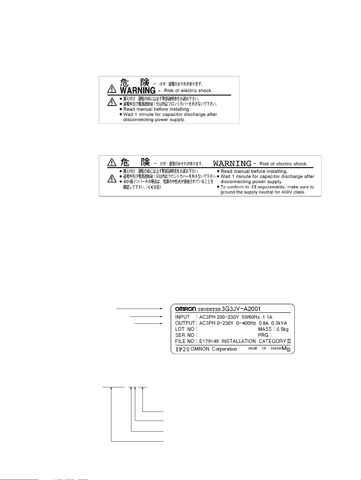
S For 3G3JV-A2001 to A2007 (0.1 to 0.75 kW) and 3G3JV-AB001 to AB004 (0.1 to
0.4 kW):
S For 3G3JV-A2015 to A2037 (1.5 to 3.7 kW), 3G3JV-AB007 to AB015 (0.75 to
1.5 kW), and 3G3JV-A4002 to A4037 (0.2 to 3.7 kW):
Checking Before Unpacking
H Checking the Product
On delivery, always check that the delivered product is the SYSDRIVE 3G3JV Inverter that you ordered.
Should you find any problems with the product, immediately contact your nearest local sales
representative.
D Checking the Nameplate
Inverter model
Input specifications
Output specifications
D Checking the Model
3G3JV-A2007
Maximum applicable motor capacity
Voltage class
Installation type
Series name: 3G3JV Series
Page 11
Maximum Applicable Motor Capacity
001 0.1 (0.1) kW
002 0.25/0.37 (0.2) kW
004 0.55 (0.4) kW
007 1.1 (0.75) kW
015 1.5 (1.5) kW
022 2.2 (2.2) kW
037 3.7 (3.7) kW
Note The figures in parentheses indicate capacities for motors used outside Japan.
Voltage Class
2 Three-phase 200-V AC input (200-V class)
B Single-phase 200-V AC input (200-V class)
4 Three-phase 400-V AC input (400-V class)
Installation Type
A Panel-mounting models (IP10 min.) or
Closed wall mounting
D Checking for Damage
Check the overall appearance and check for damage or scratches resulting from transportation.
H Checking the Accessories
This manual is the only accessory provided with the 3G3JV. Set screws and other necessary parts must
be provided by the user.
Page 12
About this Manual
This manual is divided into the chapters described in the following table. Information is organized by
application area to enable you to use the manual more efficiently.
Chapter Contents
Chapter 1 Overview Describes features and nomenclature.
Chapter 2 Design Provides dimensions, installation methods, wiring methods, peripheral
device design information, and peripheral device selection information.
Chapter 3 Preparing for Operation
and Monitoring
Chapter 4 Test Run Describes the method for controlling a motor through the frequency
Chapter 5 Basic Operation Describes basic Inverter control functions for users not familiar with
Chapter 6 Advanced Operation Describes all of the functions provided by the Inverter. These functions
Chapter 7 Communications Describes the RS-422/485 Communications Unit and the
Chapter 8 Maintenance Operations Provides maintenance, inspection, and troubleshooting information.
Chapter 9 Specifications Provides Inverter specifications, as well as the specifications and
Chapter 10 List of Parameters Lists basic information on Inverter parameters as a reference for users
Chapter 11 Using the Inverter for a
Motor
Describes nomenclature and Digital Operator procedures for operating
and monitoring Inverters.
adjuster on the front of the Inverter. This can be used for trial
operation of the system.
Inverters. The functions that must be understood to drive a motor with
an Inverter are described.
will enable more advanced applications, and includes functions that
will improve motor control through the Inverter, such as
responsiveness (torque characteristics), increasing speed accuracy,
PID control, overtorque detection, and other functions.
general-purpose RS-422/485 communications functions provided by
the Inverter, including connection methods and sample programming
for SYSMAC Programmable Controllers.
dimensions of peripheral devices.
already familiar with Inverter operation. Parameters are listed in order
with the page numbers of further information for easy reference.
Describes information on using the Inverter for a motor.
Page 13
Read and Understand this Manual
Á
Á
Á
Á
Á
Á
Á
Á
Á
Á
Á
Á
Á
Á
Á
Please read and understand this manual before using the product. Please consult your OMRON
representative if you have any questions or comments.
Warranty and Limitations of Liability
WARRANTY
OMRON’s exclusive warranty is that the products are free from defects in materials and workmanship for
БББББББББББББББББББББББББББББББ
a period of one year (or other period if specified) from date of sale by OMRON.
БББББББББББББББББББББББББББББББ
OMRON MAKES NO WARRANTY OR REPRESENTATION, EXPRESS OR IMPLIED, REGARDING
БББББББББББББББББББББББББББББББ
NON–INFRINGEMENT, MERCHANTABILITY, OR FITNESS FOR PARTICULAR PURPOSE OF THE
БББББББББББББББББББББББББББББББ
PRODUCTS. ANY BUYER OR USER ACKNOWLEDGES THAT THE BUYER OR USER ALONE HAS
БББББББББББББББББББББББББББББББ
DETERMINED THAT THE PRODUCTS WILL SUITABLY MEET THE REQUIREMENTS OF THEIR
INTENDED USE. OMRON DISCLAIMS ALL OTHER WARRANTIES, EXPRESS OR IMPLIED.
БББББББББББББББББББББББББББББББ
БББББББББББББББББББББББББББББББ
LIMITATIONS OF LIABILITY
OMRON SHALL NOT BE RESPONSIBLE FOR SPECIAL, INDIRECT, OR CONSEQUENTIAL
DAMAGES, LOSS OF PROFITS OR COMMERCIAL LOSS IN ANY WAY CONNECTED WITH THE
БББББББББББББББББББББББББББББББ
PRODUCTS, WHETHER SUCH CLAIM IS BASED ON CONTRACT, WARRANTY, NEGLIGENCE, OR
БББББББББББББББББББББББББББББББ
STRICT LIABILITY.
БББББББББББББББББББББББББББББББ
In no event shall the responsibility of OMRON for any act exceed the individual price of the product on
БББББББББББББББББББББББББББББББ
which liability is asserted.
БББББББББББББББББББББББББББББББ
IN NO EVENT SHALL OMRON BE RESPONSIBLE FOR WARRANTY, REPAIR, OR OTHER CLAIMS
БББББББББББББББББББББББББББББББ
REGARDING THE PRODUCTS UNLESS OMRON’S ANALYSIS CONFIRMS THAT THE PRODUCTS
БББББББББББББББББББББББББББББББ
WERE PROPERLY HANDLED, STORED, INSTALLED, AND MAINTAINED AND NOT SUBJECT TO
БББББББББББББББББББББББББББББББ
CONTAMINATION, ABUSE, MISUSE, OR INAPPROPRIATE MODIFICATION OR REPAIR.
Page 14
Application Considerations
Á
Á
Á
Á
Á
Á
Á
Á
Á
Á
Á
Á
Á
Á
Á
Á
Á
Á
Á
Á
Á
Á
SUITABILITY FOR USE
OMRON shall not be responsible for conformity with any standards, codes, or regulations that apply to
БББББББББББББББББББББББББББББББ
the combination of products in the customer’s application or use of the products.
БББББББББББББББББББББББББББББББ
At the customer’s request, OMRON will provide applicable third party certification documents identifying
БББББББББББББББББББББББББББББББ
ratings and limitations of use that apply to the products. This information by itself is not sufficient for a
БББББББББББББББББББББББББББББББ
complete determination of the suitability of the products in combination with the end product, machine,
БББББББББББББББББББББББББББББББ
system, or other application or use.
БББББББББББББББББББББББББББББББ
The following are some examples of applications for which particular attention must be given. This is not
БББББББББББББББББББББББББББББББ
intended to be an exhaustive list of all possible uses of the products, nor is it intended to imply that the
БББББББББББББББББББББББББББББББ
uses listed may be suitable for the products:
БББББББББББББББББББББББББББББББ
• Outdoor use, uses involving potential chemical contamination or electrical interference, or conditions
БББББББББББББББББББББББББББББББ
or uses not described in this manual.
БББББББББББББББББББББББББББББББ
• Nuclear energy control systems, combustion systems, railroad systems, aviation systems, medical
БББББББББББББББББББББББББББББББ
equipment, amusement machines, vehicles, safety equipment, and installations subject to separate
БББББББББББББББББББББББББББББББ
industry or government regulations.
БББББББББББББББББББББББББББББББ
• Systems, machines, and equipment that could present a risk to life or property.
БББББББББББББББББББББББББББББББ
Please know and observe all prohibitions of use applicable to the products.
БББББББББББББББББББББББББББББББ
БББББББББББББББББББББББББББББББ
NEVER USE THE PRODUCTS FOR AN APPLICATION INVOLVING SERIOUS RISK TO LIFE OR
БББББББББББББББББББББББББББББББ
PROPERTY WITHOUT ENSURING THAT THE SYSTEM AS A WHOLE HAS BEEN DESIGNED TO
ADDRESS THE RISKS, AND THAT THE OMRON PRODUCTS ARE PROPERLY RATED AND
БББББББББББББББББББББББББББББББ
INSTALLED FOR THE INTENDED USE WITHIN THE OVERALL EQUIPMENT OR SYSTEM.
БББББББББББББББББББББББББББББББ
БББББББББББББББББББББББББББББББ
PROGRAMMABLE PRODUCTS
OMRON shall not be responsible for the user’s programming of a programmable product, or any
БББББББББББББББББББББББББББББББ
consequence thereof.
Page 15
Disclaimers
Á
Á
Á
Á
Á
Á
Á
Á
Á
Á
Á
Á
Á
CHANGE IN SPECIFICATIONS
БББББББББББББББББББББББББББББББ
Product specifications and accessories may be changed at any time based on improvements and other
reasons.
БББББББББББББББББББББББББББББББ
БББББББББББББББББББББББББББББББ
It is our practice to change model numbers when published ratings or features are changed, or when
significant construction changes are made. However, some specifications of the products may be
БББББББББББББББББББББББББББББББ
changed without any notice. When in doubt, special model numbers may be assigned to fix or establish
БББББББББББББББББББББББББББББББ
key specifications for your application on your request. Please consult with your OMRON representative
БББББББББББББББББББББББББББББББ
at any time to confirm actual specifications of purchased products.
БББББББББББББББББББББББББББББББ
DIMENSIONS AND WEIGHTS
Dimensions and weights are nominal and are not to be used for manufacturing purposes, even when
tolerances are shown.
БББББББББББББББББББББББББББББББ
PERFORMANCE DATA
Performance data given in this manual is provided as a guide for the user in determining suitability and
БББББББББББББББББББББББББББББББ
does not constitute a warranty. It may represent the result of OMRON’s test conditions, and the users
БББББББББББББББББББББББББББББББ
must correlate it to actual application requirements. Actual performance is subject to the OMRON
БББББББББББББББББББББББББББББББ
Warranty and Limitations of Liability.
БББББББББББББББББББББББББББББББ
The information in this manual has been carefully checked and is believed to be accurate; however, no
responsibility is assumed for clerical, typographical, or proofreading errors, or omissions.
БББББББББББББББББББББББББББББББ
ERRORS AND OMISSIONS
Page 16

Page 17

Table of Contents
Chapter 1. Overview 1-1. . . . . . . . . . . . . . . . . . . . . . . . . . . . . . . . . . . . . . . .
1-1 Function 1-2. . . . . . . . . . . . . . . . . . . . . . . . . . . . . . . . . . . . . . . . . . . . . . . . . . . . . . . . . . . . . . . . . . .
1-2 Nomenclature 1-4. . . . . . . . . . . . . . . . . . . . . . . . . . . . . . . . . . . . . . . . . . . . . . . . . . . . . . . . . . . . . . .
Chapter 2. Design 2-1. . . . . . . . . . . . . . . . . . . . . . . . . . . . . . . . . . . . . . . . . .
2-1 Installation 2-2. . . . . . . . . . . . . . . . . . . . . . . . . . . . . . . . . . . . . . . . . . . . . . . . . . . . . . . . . . . . . . . . .
2-1-1 Dimensions 2-2. . . . . . . . . . . . . . . . . . . . . . . . . . . . . . . . . . . . . . . . . . . . . . . . . . . . . . . . . .
2-1-2 Installation Conditions 2-4. . . . . . . . . . . . . . . . . . . . . . . . . . . . . . . . . . . . . . . . . . . . . . . . .
2-2 Wiring 2-7. . . . . . . . . . . . . . . . . . . . . . . . . . . . . . . . . . . . . . . . . . . . . . . . . . . . . . . . . . . . . . . . . . . .
2-2-1 Removing and Mounting the Covers 2-8. . . . . . . . . . . . . . . . . . . . . . . . . . . . . . . . . . . . . .
2-2-2 Terminal Block 2-9. . . . . . . . . . . . . . . . . . . . . . . . . . . . . . . . . . . . . . . . . . . . . . . . . . . . . . .
2-2-3 Standard Connections 2-14. . . . . . . . . . . . . . . . . . . . . . . . . . . . . . . . . . . . . . . . . . . . . . . . . .
2-2-4 Wiring around the Main Circuit 2-15. . . . . . . . . . . . . . . . . . . . . . . . . . . . . . . . . . . . . . . . . .
2-2-5 Wiring Control Circuit Terminals 2-26. . . . . . . . . . . . . . . . . . . . . . . . . . . . . . . . . . . . . . . . .
2-2-6 Conforming to EC Directive 2-28. . . . . . . . . . . . . . . . . . . . . . . . . . . . . . . . . . . . . . . . . . . . .
Chapter 3. Preparing for Operation and Monitoring 3-1. . . . . . . . . . . . .
3-1 Nomenclature 3-2. . . . . . . . . . . . . . . . . . . . . . . . . . . . . . . . . . . . . . . . . . . . . . . . . . . . . . . . . . . . . . .
3-1-1 Part Names and Functions 3-2. . . . . . . . . . . . . . . . . . . . . . . . . . . . . . . . . . . . . . . . . . . . . .
3-1-2 Drive Mode and Program Mode 3-3. . . . . . . . . . . . . . . . . . . . . . . . . . . . . . . . . . . . . . . . . .
3-1-3 Outline of Operation 3-5. . . . . . . . . . . . . . . . . . . . . . . . . . . . . . . . . . . . . . . . . . . . . . . . . . .
3-2 Parameter Copy and Verify Function 3-10. . . . . . . . . . . . . . . . . . . . . . . . . . . . . . . . . . . . . . . . . . . .
3-2-1 Parameters for the Parameter Copy and Verify Function 3-10. . . . . . . . . . . . . . . . . . . . . . .
3-2-2 Procedure for Copying Parameters 3-11. . . . . . . . . . . . . . . . . . . . . . . . . . . . . . . . . . . . . . . .
3-2-3 Parameter Read Prohibit (Prohibiting Writing to Digital Operator) 3-16. . . . . . . . . . . . . .
3-2-4 Error Displays for the Parameter Copy and Verify Function 3-17. . . . . . . . . . . . . . . . . . . .
Chapter 4. Test Run 4-1. . . . . . . . . . . . . . . . . . . . . . . . . . . . . . . . . . . . . . . .
4-1 Procedure for Test Run 4-3. . . . . . . . . . . . . . . . . . . . . . . . . . . . . . . . . . . . . . . . . . . . . . . . . . . . . . .
4-2 Operation Example 4-5. . . . . . . . . . . . . . . . . . . . . . . . . . . . . . . . . . . . . . . . . . . . . . . . . . . . . . . . . .
Chapter 5. Basic Operation 5-1. . . . . . . . . . . . . . . . . . . . . . . . . . . . . . . . . .
5-1 Initial Settings 5-2. . . . . . . . . . . . . . . . . . . . . . . . . . . . . . . . . . . . . . . . . . . . . . . . . . . . . . . . . . . . . .
5-2 V/f Control 5-4. . . . . . . . . . . . . . . . . . . . . . . . . . . . . . . . . . . . . . . . . . . . . . . . . . . . . . . . . . . . . . . . .
5-3 Setting the Local/Remote Mode 5-6. . . . . . . . . . . . . . . . . . . . . . . . . . . . . . . . . . . . . . . . . . . . . . . .
5-4 Selecting the Operation Command 5-7. . . . . . . . . . . . . . . . . . . . . . . . . . . . . . . . . . . . . . . . . . . . . .
5-5 Setting the Frequency Reference 5-8. . . . . . . . . . . . . . . . . . . . . . . . . . . . . . . . . . . . . . . . . . . . . . . .
5-5-1 Selecting the Frequency Reference 5-8. . . . . . . . . . . . . . . . . . . . . . . . . . . . . . . . . . . . . . .
5-5-2 Upper and Lower Frequency Reference Limits 5-9. . . . . . . . . . . . . . . . . . . . . . . . . . . . . .
5-5-3 Adjusting the Analog Input 5-9. . . . . . . . . . . . . . . . . . . . . . . . . . . . . . . . . . . . . . . . . . . . .
5-5-4 Setting Frequency References through Key Sequences 5-10. . . . . . . . . . . . . . . . . . . . . . . .
5-6 Setting the Acceleration/Deceleration Time 5-14. . . . . . . . . . . . . . . . . . . . . . . . . . . . . . . . . . . . . . .
5-7 Selecting the Reverse Rotation-prohibit 5-16. . . . . . . . . . . . . . . . . . . . . . . . . . . . . . . . . . . . . . . . . .
5-8 Selecting the Interruption Mode 5-17. . . . . . . . . . . . . . . . . . . . . . . . . . . . . . . . . . . . . . . . . . . . . . . .
5-9 Multi-function I/O 5-18. . . . . . . . . . . . . . . . . . . . . . . . . . . . . . . . . . . . . . . . . . . . . . . . . . . . . . . . . . .
5-9-1 Multi-function Input 5-18. . . . . . . . . . . . . . . . . . . . . . . . . . . . . . . . . . . . . . . . . . . . . . . . . . .
5-9-2 Multi-function Output 5-21. . . . . . . . . . . . . . . . . . . . . . . . . . . . . . . . . . . . . . . . . . . . . . . . . .
5-10 Analog Monitor Output 5-23. . . . . . . . . . . . . . . . . . . . . . . . . . . . . . . . . . . . . . . . . . . . . . . . . . . . . . .
Page 18

Table of Contents
Chapter 6. Advanced Operation 6-1. . . . . . . . . . . . . . . . . . . . . . . . . . . . . .
6-1 Setting the Carrier Frequency 6-2. . . . . . . . . . . . . . . . . . . . . . . . . . . . . . . . . . . . . . . . . . . . . . . . . .
6-2 DC Injection Braking Function 6-5. . . . . . . . . . . . . . . . . . . . . . . . . . . . . . . . . . . . . . . . . . . . . . . . .
6-3 Stall Prevention Function 6-6. . . . . . . . . . . . . . . . . . . . . . . . . . . . . . . . . . . . . . . . . . . . . . . . . . . . .
6-4 Overtorque Detection Function 6-9. . . . . . . . . . . . . . . . . . . . . . . . . . . . . . . . . . . . . . . . . . . . . . . . .
6-5 Torque Compensation Function 6-11. . . . . . . . . . . . . . . . . . . . . . . . . . . . . . . . . . . . . . . . . . . . . . . . .
6-6 Slip Compensation Function 6-12. . . . . . . . . . . . . . . . . . . . . . . . . . . . . . . . . . . . . . . . . . . . . . . . . . .
6-7 Other Functions 6-14. . . . . . . . . . . . . . . . . . . . . . . . . . . . . . . . . . . . . . . . . . . . . . . . . . . . . . . . . . . . .
6-7-1 Motor Protection Characteristics (n33 and n34) 6-14. . . . . . . . . . . . . . . . . . . . . . . . . . . . .
6-7-2 Cooling Fan Operation Function (n35) 6-14. . . . . . . . . . . . . . . . . . . . . . . . . . . . . . . . . . . .
6-7-3 Momentary Power Interruption Compensation (n47) 6-15. . . . . . . . . . . . . . . . . . . . . . . . .
6-7-4 Fault Retry (n48) 6-15. . . . . . . . . . . . . . . . . . . . . . . . . . . . . . . . . . . . . . . . . . . . . . . . . . . . . .
6-7-5 Frequency Jump Function (n49 to n51) 6-16. . . . . . . . . . . . . . . . . . . . . . . . . . . . . . . . . . . .
6-7-6 Frequency Detection Function 6-17. . . . . . . . . . . . . . . . . . . . . . . . . . . . . . . . . . . . . . . . . . .
6-7-7 UP/DOWN Command Frequency Memory (n62) 6-19. . . . . . . . . . . . . . . . . . . . . . . . . . . .
6-7-8 Error History (n78) 6-21. . . . . . . . . . . . . . . . . . . . . . . . . . . . . . . . . . . . . . . . . . . . . . . . . . . .
Chapter 7. Communications 7-1. . . . . . . . . . . . . . . . . . . . . . . . . . . . . . . . . .
7-1 RS-422/485 Communications Unit 7-2. . . . . . . . . . . . . . . . . . . . . . . . . . . . . . . . . . . . . . . . . . . . . .
7-1-1 Overview 7-2. . . . . . . . . . . . . . . . . . . . . . . . . . . . . . . . . . . . . . . . . . . . . . . . . . . . . . . . . . . .
7-1-2 External Dimensions 7-2. . . . . . . . . . . . . . . . . . . . . . . . . . . . . . . . . . . . . . . . . . . . . . . . . . .
7-1-3 Names of Parts 7-3. . . . . . . . . . . . . . . . . . . . . . . . . . . . . . . . . . . . . . . . . . . . . . . . . . . . . . .
7-1-4 Mounting Procedure 7-3. . . . . . . . . . . . . . . . . . . . . . . . . . . . . . . . . . . . . . . . . . . . . . . . . . .
7-2 Inverter Settings 7-5. . . . . . . . . . . . . . . . . . . . . . . . . . . . . . . . . . . . . . . . . . . . . . . . . . . . . . . . . . . . .
7-2-1 Setting the Communications Conditions 7-5. . . . . . . . . . . . . . . . . . . . . . . . . . . . . . . . . . .
7-2-2 Operation Command Selection (n02) 7-8. . . . . . . . . . . . . . . . . . . . . . . . . . . . . . . . . . . . . .
7-2-3 Frequency Reference Input Selection (n03) 7-8. . . . . . . . . . . . . . . . . . . . . . . . . . . . . . . . .
7-2-4 Setting the Multi-function Inputs (n36 to n39) 7-9. . . . . . . . . . . . . . . . . . . . . . . . . . . . . .
7-3 Message Communications Basic Format 7-10. . . . . . . . . . . . . . . . . . . . . . . . . . . . . . . . . . . . . . . . .
7-4 DSR Message and Response 7-13. . . . . . . . . . . . . . . . . . . . . . . . . . . . . . . . . . . . . . . . . . . . . . . . . . .
7-4-1 Data Read (Function Code: 03 Hex) 7-13. . . . . . . . . . . . . . . . . . . . . . . . . . . . . . . . . . . . . .
7-4-2 Data Write/Broadcast Data Write (Function Code: 10 Hex) 7-15. . . . . . . . . . . . . . . . . . . .
7-4-3 Loop-back Test (Function Code: 08 Hex) 7-18. . . . . . . . . . . . . . . . . . . . . . . . . . . . . . . . . .
7-5 Enter Command 7-20. . . . . . . . . . . . . . . . . . . . . . . . . . . . . . . . . . . . . . . . . . . . . . . . . . . . . . . . . . . . .
7-6 Setting the Communications Data 7-21. . . . . . . . . . . . . . . . . . . . . . . . . . . . . . . . . . . . . . . . . . . . . . .
7-7 Register Number Allocations in Detail 7-23. . . . . . . . . . . . . . . . . . . . . . . . . . . . . . . . . . . . . . . . . . .
7-7-1 I/O Function 7-23. . . . . . . . . . . . . . . . . . . . . . . . . . . . . . . . . . . . . . . . . . . . . . . . . . . . . . . . .
7-7-2 Monitor Functions 7-24. . . . . . . . . . . . . . . . . . . . . . . . . . . . . . . . . . . . . . . . . . . . . . . . . . . . .
7-8 Communications Error Codes 7-27. . . . . . . . . . . . . . . . . . . . . . . . . . . . . . . . . . . . . . . . . . . . . . . . . .
7-9 Self-diagnostic Test 7-29. . . . . . . . . . . . . . . . . . . . . . . . . . . . . . . . . . . . . . . . . . . . . . . . . . . . . . . . . .
7-10 Communications with Programmable Controller 7-30. . . . . . . . . . . . . . . . . . . . . . . . . . . . . . . . . . .
7-10-1 Available Programmable Controllers and Peripheral Devices 7-30. . . . . . . . . . . . . . . . . . .
7-10-2 Wiring the Communications Line 7-35. . . . . . . . . . . . . . . . . . . . . . . . . . . . . . . . . . . . . . . .
7-10-3 Outline of Protocol Macro Function 7-36. . . . . . . . . . . . . . . . . . . . . . . . . . . . . . . . . . . . . . .
7-10-4 Creating a Project File 7-40. . . . . . . . . . . . . . . . . . . . . . . . . . . . . . . . . . . . . . . . . . . . . . . . .
7-10-5 Ladder Program 7-50. . . . . . . . . . . . . . . . . . . . . . . . . . . . . . . . . . . . . . . . . . . . . . . . . . . . . .
7-10-6 Communications Response Time 7-54. . . . . . . . . . . . . . . . . . . . . . . . . . . . . . . . . . . . . . . . .
Page 19

Table of Contents
Chapter 8. Maintenance Operations 8-1. . . . . . . . . . . . . . . . . . . . . . . . . .
8-1 Protective and Diagnostic Functions 8-2. . . . . . . . . . . . . . . . . . . . . . . . . . . . . . . . . . . . . . . . . . . . .
8-1-1 Fault Detection (Fatal Error) 8-2. . . . . . . . . . . . . . . . . . . . . . . . . . . . . . . . . . . . . . . . . . . .
8-1-2 Warning Detection (Nonfatal Error) 8-7. . . . . . . . . . . . . . . . . . . . . . . . . . . . . . . . . . . . . . .
8-2 Troubleshooting 8-10. . . . . . . . . . . . . . . . . . . . . . . . . . . . . . . . . . . . . . . . . . . . . . . . . . . . . . . . . . . . .
8-2-1 Parameters Fail Set 8-10. . . . . . . . . . . . . . . . . . . . . . . . . . . . . . . . . . . . . . . . . . . . . . . . . . . .
8-2-2 Motor Fails to Operate 8-10. . . . . . . . . . . . . . . . . . . . . . . . . . . . . . . . . . . . . . . . . . . . . . . . .
8-2-3 Motor Rotates in the Wrong Direction 8-12. . . . . . . . . . . . . . . . . . . . . . . . . . . . . . . . . . . . .
8-2-4 Motor Outputs No Torque or Acceleration is Slow 8-12. . . . . . . . . . . . . . . . . . . . . . . . . . .
8-2-5 Motor Deceleration is Slow 8-12. . . . . . . . . . . . . . . . . . . . . . . . . . . . . . . . . . . . . . . . . . . . .
8-2-6 Motor Burns 8-12. . . . . . . . . . . . . . . . . . . . . . . . . . . . . . . . . . . . . . . . . . . . . . . . . . . . . . . . .
8-2-7 Controller or AM Radio Receives Noise when Inverter is Started 8-13. . . . . . . . . . . . . . .
8-2-8 Ground Fault Interrupter is Actuated when Inverter is Started 8-13. . . . . . . . . . . . . . . . . .
8-2-9 Mechanical Vibration 8-14. . . . . . . . . . . . . . . . . . . . . . . . . . . . . . . . . . . . . . . . . . . . . . . . . .
8-2-10 Motor Rotates after Output of Inverter is Turned Off 8-14. . . . . . . . . . . . . . . . . . . . . . . . .
8-2-11 Detects OV when Motor Starts and Motor Stalls 8-14. . . . . . . . . . . . . . . . . . . . . . . . . . . . .
8-2-12 Output Frequency Does Not Reach Frequency Reference 8-15. . . . . . . . . . . . . . . . . . . . . .
8-2-13 Inverter Does Not Run Because EF (Simultaneous Input of Forward and Reverse Commands)
is Detected, or Motor Rotates Momentarily While Control Device Power is OFF 8-15. . .
8-3 Maintenance and Inspection 8-16. . . . . . . . . . . . . . . . . . . . . . . . . . . . . . . . . . . . . . . . . . . . . . . . . . .
Chapter 9. Specifications 9-1. . . . . . . . . . . . . . . . . . . . . . . . . . . . . . . . . . . .
9-1 Inverter Specifications 9-2. . . . . . . . . . . . . . . . . . . . . . . . . . . . . . . . . . . . . . . . . . . . . . . . . . . . . . . .
9-2 Specifications of Accessories 9-6. . . . . . . . . . . . . . . . . . . . . . . . . . . . . . . . . . . . . . . . . . . . . . . . . .
9-2-1 List of Accessories 9-6. . . . . . . . . . . . . . . . . . . . . . . . . . . . . . . . . . . . . . . . . . . . . . . . . . . .
9-2-2 Adapter Panel 9-8. . . . . . . . . . . . . . . . . . . . . . . . . . . . . . . . . . . . . . . . . . . . . . . . . . . . . . . .
9-2-3 RS-422/485 Communications Unit 9-9. . . . . . . . . . . . . . . . . . . . . . . . . . . . . . . . . . . . . . . .
9-2-4 Fan Unit 9-10. . . . . . . . . . . . . . . . . . . . . . . . . . . . . . . . . . . . . . . . . . . . . . . . . . . . . . . . . . . .
9-2-5 Scaling Meter 9-10. . . . . . . . . . . . . . . . . . . . . . . . . . . . . . . . . . . . . . . . . . . . . . . . . . . . . . . .
9-2-6 Digital Operator 9-12. . . . . . . . . . . . . . . . . . . . . . . . . . . . . . . . . . . . . . . . . . . . . . . . . . . . . .
9-2-7 Digital Operator Case 9-13. . . . . . . . . . . . . . . . . . . . . . . . . . . . . . . . . . . . . . . . . . . . . . . . . .
9-2-8 Digital Operator Connection Cable 9-14. . . . . . . . . . . . . . . . . . . . . . . . . . . . . . . . . . . . . . .
9-2-9 DC Reactor 9-14. . . . . . . . . . . . . . . . . . . . . . . . . . . . . . . . . . . . . . . . . . . . . . . . . . . . . . . . . .
9-2-10 DIN Track Mounting Bracket 9-15. . . . . . . . . . . . . . . . . . . . . . . . . . . . . . . . . . . . . . . . . . . .
9-2-11 AC Reactor 9-17. . . . . . . . . . . . . . . . . . . . . . . . . . . . . . . . . . . . . . . . . . . . . . . . . . . . . . . . . .
9-3 Option Specifications 9-19. . . . . . . . . . . . . . . . . . . . . . . . . . . . . . . . . . . . . . . . . . . . . . . . . . . . . . . .
9-3-1 EMC-compatible Noise Filter 9-19. . . . . . . . . . . . . . . . . . . . . . . . . . . . . . . . . . . . . . . . . . .
9-3-2 Simple Input Noise Filter 9-24. . . . . . . . . . . . . . . . . . . . . . . . . . . . . . . . . . . . . . . . . . . . . . .
9-3-3 Output Noise Filter 9-26. . . . . . . . . . . . . . . . . . . . . . . . . . . . . . . . . . . . . . . . . . . . . . . . . . . .
Chapter 10. List of Parameters 10-1. . . . . . . . . . . . . . . . . . . . . . . . . . . . . . .
Chapter 11. Using the Inverter for a Motor 11-1. . . . . . . . . . . . . . . . . . . . .
Revision History R-1. . . . . . . . . . . . . . . . . . . . . . . . . . . . . . . . .
Page 20
Overview
1-1 Function
1-2 Nomenclature
1
Chapter 1
Page 21
p
g
gp
g
p
g
Overview Chapter 1
1-1 Function
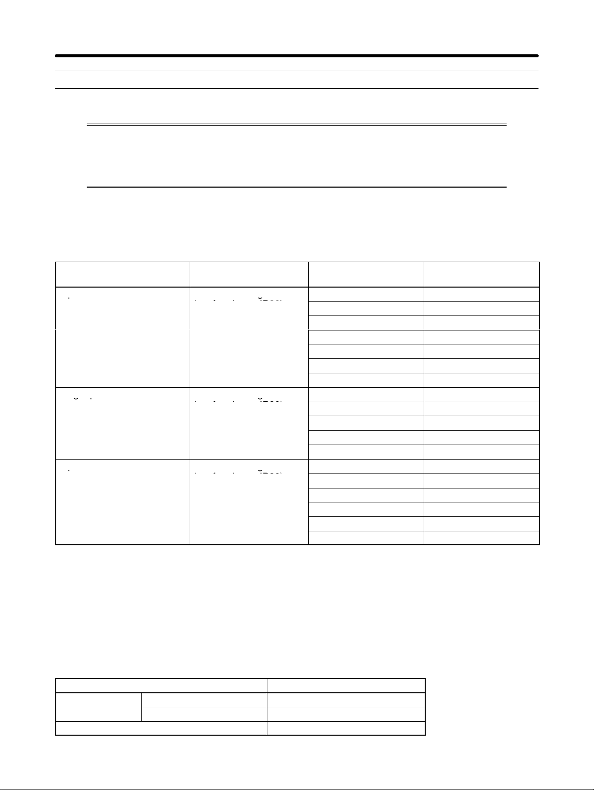
The compact simple SYSDRIVE 3G3JV-Series Inverter ensures greater ease of use
than any conventional model.
The 3G3JV Inverter meets EC Directives and UL/cUL standard requirements for worldwide use.
H SYSDRIVE 3G3JV Inverter Models
• The following 3-phase and single-phase 200-V AC-class, and 3-phase 400-V AC-class 3G3JV models are available.
Rated voltage Protective structure Maximum applied
3-phase 200 V AC Panel-mounting models
(conforming to IP20)
Single-phase 200 V AC Panel-mounting models
(conforming to IP20)
3-phase 400 V AC Panel-mounting models
(conforming to IP20)
Model
motor capacity
0.1 (0.1) kW 3G3JV-A2001
0.25 (0.2) kW 3G3JV-A2002
0.55 (0.4) kW 3G3JV-A2004
1.1 (0.75) kW 3G3JV-A2007
1.5 (1.5) kW 3G3JV-A2015
2.2 (2.2) kW 3G3JV-A2022
3.7 (3.7) kW 3G3JV-A2037
0.1 (0.1) kW 3G3JV-AB001
0.25 (0.2) kW 3G3JV-AB002
0.55 (0.4) kW 3G3JV-AB004
1.1 (0.75) kW 3G3JV-AB007
1.5 (1.5) kW 3G3JV-AB015
0.37 (0.2) kW 3G3JV-A4002
0.55 (0.4) kW 3G3JV-A4004
1.1 (0.75) kW 3G3JV-A4007
1.5 (1.5) kW 3G3JV-A4015
2.2 (2.2) kW 3G3JV-A4022
3.7 (3.7) kW 3G3JV-A4037
Note 1. The figures in parentheses indicate typical motor capacities in Japan.
Note 2. It is not possible to connect a Braking Resistor or Braking Unit to a 3G3JV-series Inverter.
Select an Inverter from another series if the application requires braking control.
H International Standards (EC Directives and UL/cUL Standards)
The 3G3JV Inverter meets the EC Directives and UL/cUL standard requirements for worldwide use.
Classification Applicable standard
EC Directives
UL/cUL UL508C
1-2
EMC Directive EN50081-2 and EN5008-2
Low-voltage Directive prEN50178
Page 22

Overview Chapter 1
H Versatile Easy-to-use Functions
• Incorporates the functions and operability ensured by the conventional 3G3EV Series.
• Easy to initialize and operate with the FREQ adjuster on the Digital Operator.
• Ease of maintenance. The cooling fan is easily replaceable. The life of the cooling fan can be pro-
longed by turning on the cooling fan only when the Inverter is in operation.
H Suppression of Harmonics
Connects to DC reactors, thus suppressing harmonics more effectively than conventional AC reactors.
Further improvement in the suppression of harmonics is possible with the combined use of the DC and
AC reactors.
1-3
Page 23
Overview Chapter 1
1-2 Nomenclature
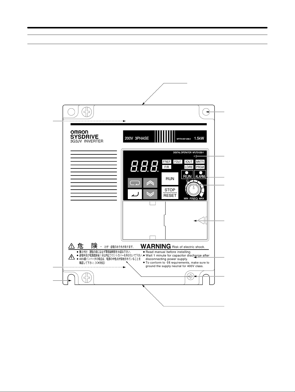
H Panel
Top protection cover
Mounting holes
Terminal
block
(Two)
Digital Operator
Terminal
block
U-shaped
cutouts
(Two)
ALARM display
RUN indicator
Optional cover
Front cover
Front cover
mounting screw
Bottom protection
cover
Note 1. The front cover functions as a terminal cover. The Digital Operator Unit cannot be removed.
Note 2. Instead of mounting holes, each of the following models has two U-shaped cutouts lo-
cated diagonally.
3G3JV-A2001 (0.1 kW), 3G3JV-A2002 (0.25 kW), 3G3JV-A2004 (0.55 kW), and
3G3JV-A2007 (1.1 kW)
3G3JV-AB001 (0.1 kW), 3G3JV-AB002 (0.25 kW), and 3G3JV-AB004 (0.55 kW)
1-4
Page 24
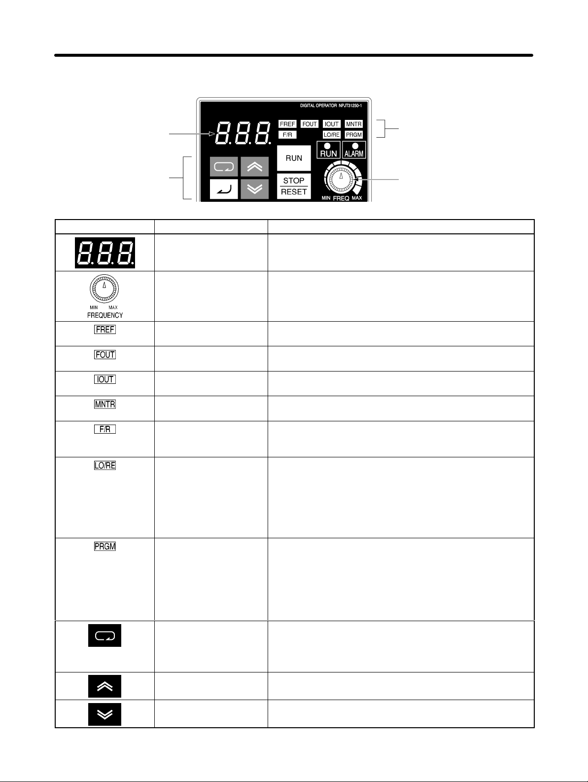
Overview Chapter 1
H Digital Operator
Indicators
Data display
(Setting/Monitor
item indicators)
Keys
Appearance Name Function
Data display Displays relevant data items, such as frequency reference,
output frequency, and parameter set values.
FREQ adjuster Sets the frequency reference within a range between 0 Hz
and the maximum frequency.
FREF indicator The frequency reference can be monitored or set while this
indicator is lit.
FOUT indicator The output frequency of the Inverter can be monitored
while this indicator is lit.
IOUT indicator The output current of the Inverter can be monitored while
this indicator is lit.
MNTR indicator The values set in U01 through U10 are monitored while
this indicator is lit.
F/R indicator The direction of rotation can be selected while this
indicator is lit when operating the Inverter with the RUN
Key.
LO/RE indicator The operation of the Inverter through the Digital Operator
or according to the set parameters is selectable while this
indicator is lit.
FREQ adjuster
Note This status of this indicator can be only monitored
while the Inverter is in operation. Any RUN command
input is ignored while this indicator is lit.
PRGM indicator The parameters in n01 through n79 can be set or
monitored while this indicator is lit.
Note While the Inverter is in operation, the parameters can
be only monitored and only some parameters can be
changed. Any RUN command input is ignored while
this indicator is lit.
Mode Key Switches the setting and monitor item indicators in
sequence.
Parameter being set will be canceled if this key is pressed
before entering the setting.
Increment Key Increases multi-function monitor numbers, parameter
numbers, and parameter set values.
Decrement Key Decreases multi-function monitor numbers, parameter
numbers, and parameter set values.
1-5
Page 25
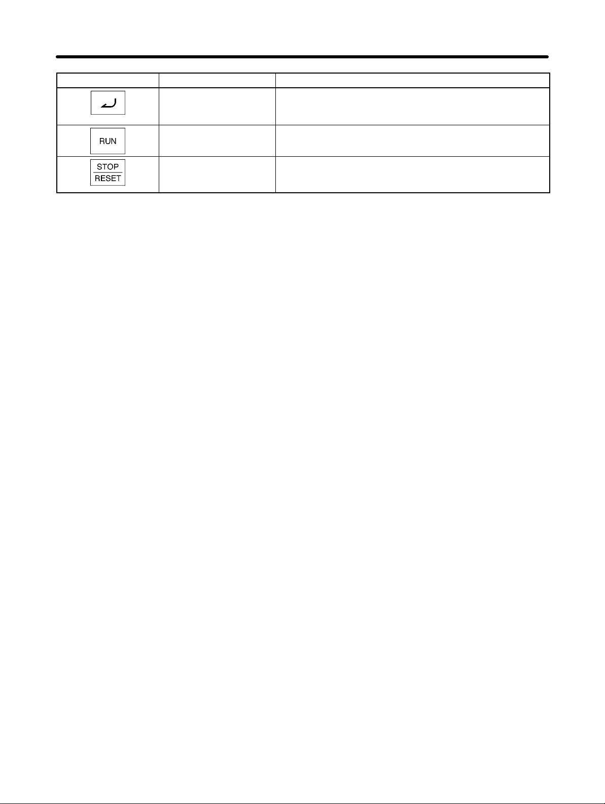
Overview Chapter 1
Appearance FunctionName
Enter Key Enters multi-function monitor numbers, parameter
numbers, and internal data values after they are set or
changed.
RUN Key Starts the Inverter running when the 3G3JV is in operation
with the Digital Operator.
STOP/RESET Key Stops the Inverter unless parameter n06 is set to disable
the STOP Key. Functions as a Reset Key when an Inverter
error occurs. (See note.)
Note For safety reasons, the reset will not work while a RUN command (forward or reverse) is in effect.
Wait until the RUN command is OFF before resetting the Inverter.
1-6
Page 26
Design
2-1 Installation
2-2 Wiring
2
Chapter 2
Page 27
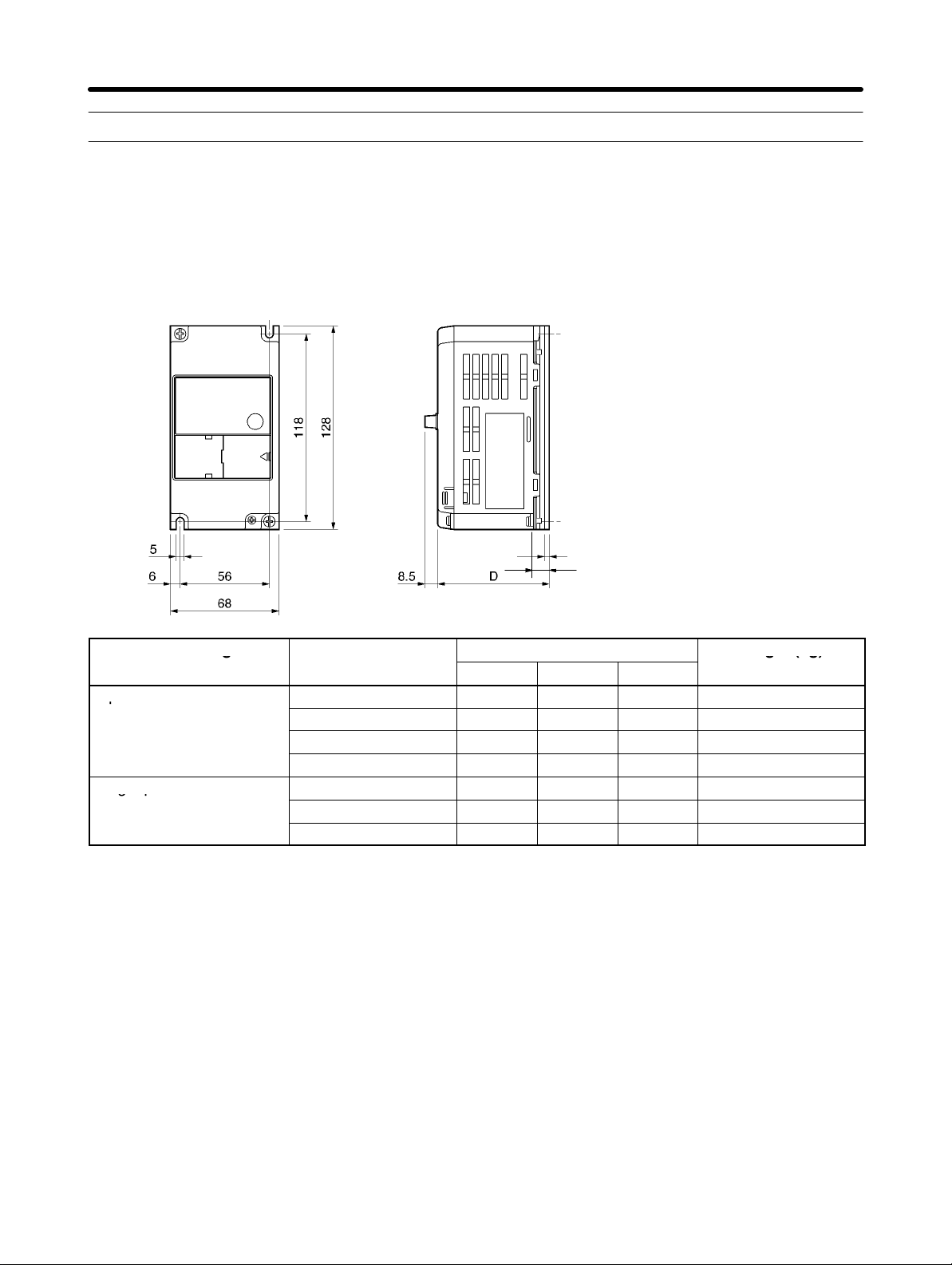
g
g(g)
p
gp
Design Chapter 2
2-1 Installation
2-1-1 Dimensions
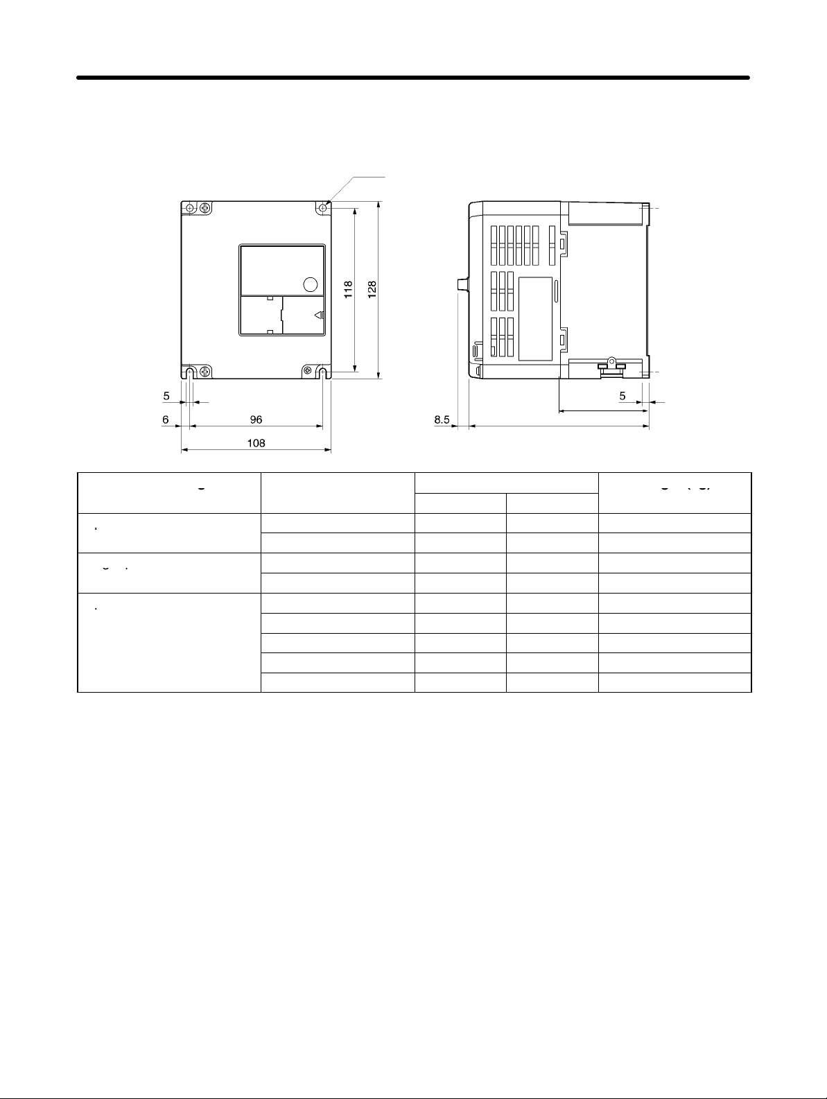
D 3G3JV-A2001 to 3G3JV-A2007 (0.1 to 0.75 kW) 3-phase 200-V AC Input
3G3JV-AB001 to 3G3JV-AB004 (0.1 to 0.4 kW) Single-phase 200-V AC Input
Rated voltage Model 3G3JV-
3-phase 200 V AC
Single-phase 200 V AC
A2001 70 10 3 Approx. 0.5
A2002 70 10 3 Approx. 0.5
A2004 102 42 5 Approx. 0.8
A2007 122 62 5 Approx. 0.9
AB001 70 10 3 Approx. 0.5
AB002 70 10 3 Approx. 0.5
AB004 112 42 5 Approx. 0.9
t
D1
Dimensions (mm)
D D1 t
Weight (kg)
2-2
Page 28
g
g(g)
p
gp
p
Design Chapter 2
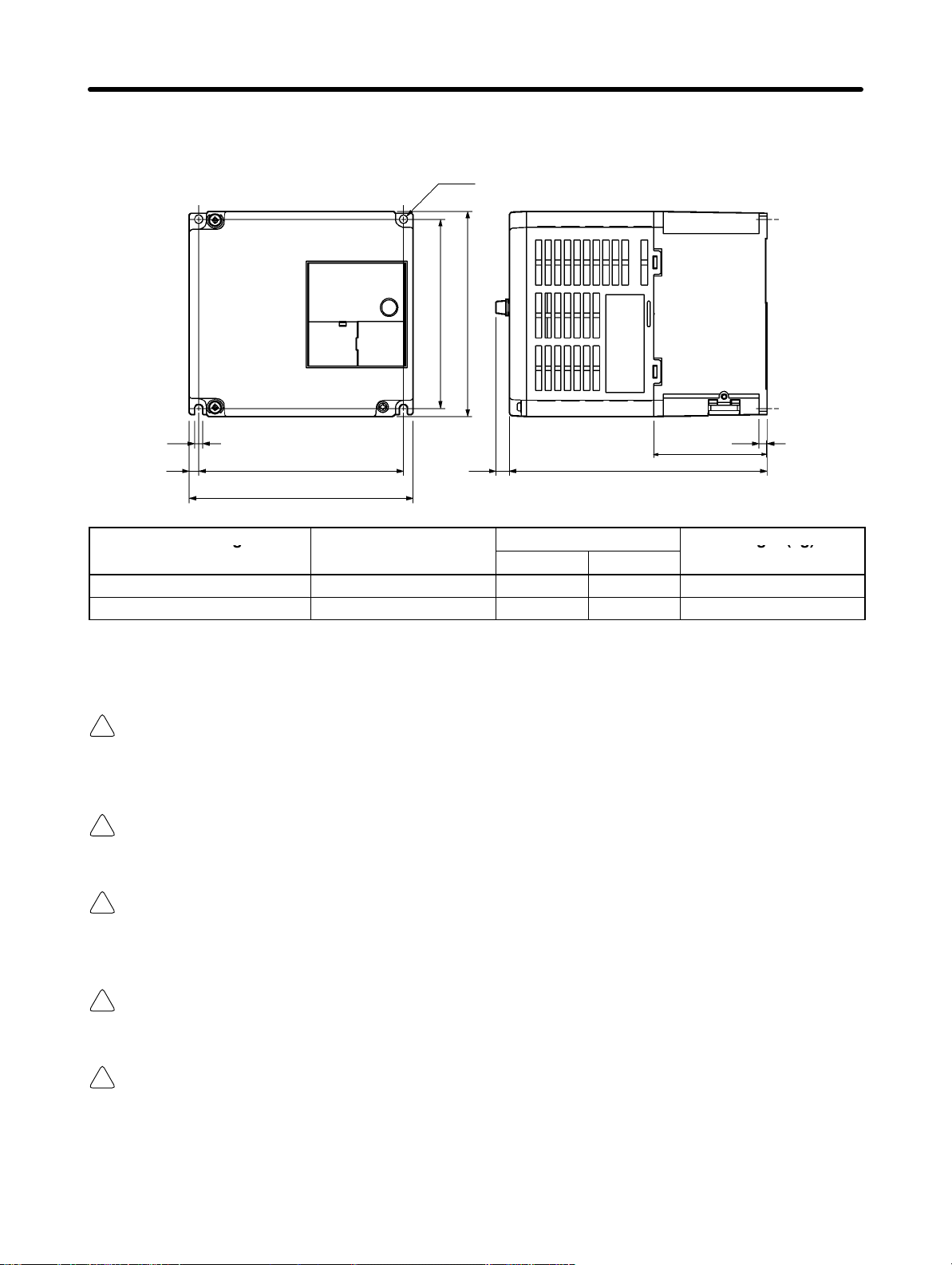
D 3G3JV-A2015 to 3G3JV-A2022 (1.5 to 2.2 kW) 3-phase 200-V AC Input
3G3JV-AB007 to 3G3JV-AB015 (0.75 to 1.5 kW) Single-phase 200-V AC Input
3G3JV-A4002 to 3G3JV-A4022 (0.2 to 2.2 kW) 3-phase 400-V AC Input
Two, 5-dia. holes
D1
D
Rated voltage Model 3G3JV-
3-phase 200 V AC
Single-phase 200 V AC
3-phase 400 V AC
A2015 129 64 Approx. 1.3
A2022 154 64 Approx. 1.5
AB007 129 64 Approx. 1.5
AB015 154 64 Approx. 1.5
A4002 81 16 Approx. 1.0
A4004 99 34 Approx. 1.1
A4007 129 64 Approx. 1.5
A4015 154 64 Approx. 1.5
A4022 154 64 Approx. 1.5
Dimensions (mm)
D D1
Weight (kg)
2-3
Page 29
g
g(g)
Design Chapter 2
D 3G3JV-A2037 (3.7 kW) 3-phase 200-V AC Input
3G3JV-A4037 (3.7 kW) 3-phase 400-V AC Input
Two, 5-dia. holes
118
128
5
6
Rated voltage Model 3G3JV-
3-phase 200 V AC A2037 161 71 Approx. 2.1
3-phase 400 V AC A4037 161 71 Approx. 2.1
128
140
8.5
D
Dimensions (mm)
D D1
5
D1
Weight (kg)
2-1-2 Installation Conditions
WARNING Provide an appropriate stopping device on the machine side to secure safety. (A
!
holding brake is not a stopping device for securing safety.) Not doing so may result in
injury.
WARNING Provide an external emergency stopping device that allows an instantaneous stop of
!
operation and power interruption. Not doing so may result in injury.
Caution Be sure to install the product in the correct direction and provide specified clear-
!
ances between the Inverter and control panel or with other devices. Not doing so
may result in fire or malfunction.
Caution Do not allow foreign objects to enter inside the product. Doing so may result in fire or
!
malfunction.
Caution Do not apply any strong impact. Doing so may result in damage to the product or
!
malfunction.
2-4
Page 30
Design Chapter 2
H Installation Direction and Dimensions
• Install the Inverter under the following conditions.
Ambient temperature for operation (panel-mounting): –10°C to 50°C
Humidity: 95% or less (no condensation)
• Install the Inverter in a clean location free from oil mist and dust. Alternatively, install it in a totally enclosed panel that is completely protected from floating dust.
• When installing or operating the Inverter, always take special care so that metal powder, oil, water, or
other foreign matter does not get into the Inverter.
• Do not install the Inverter on inflammable material such as wood.
H Direction
• Install the Inverter on a vertical surface so that the characters on the nameplate are oriented upward.
H Dimensions
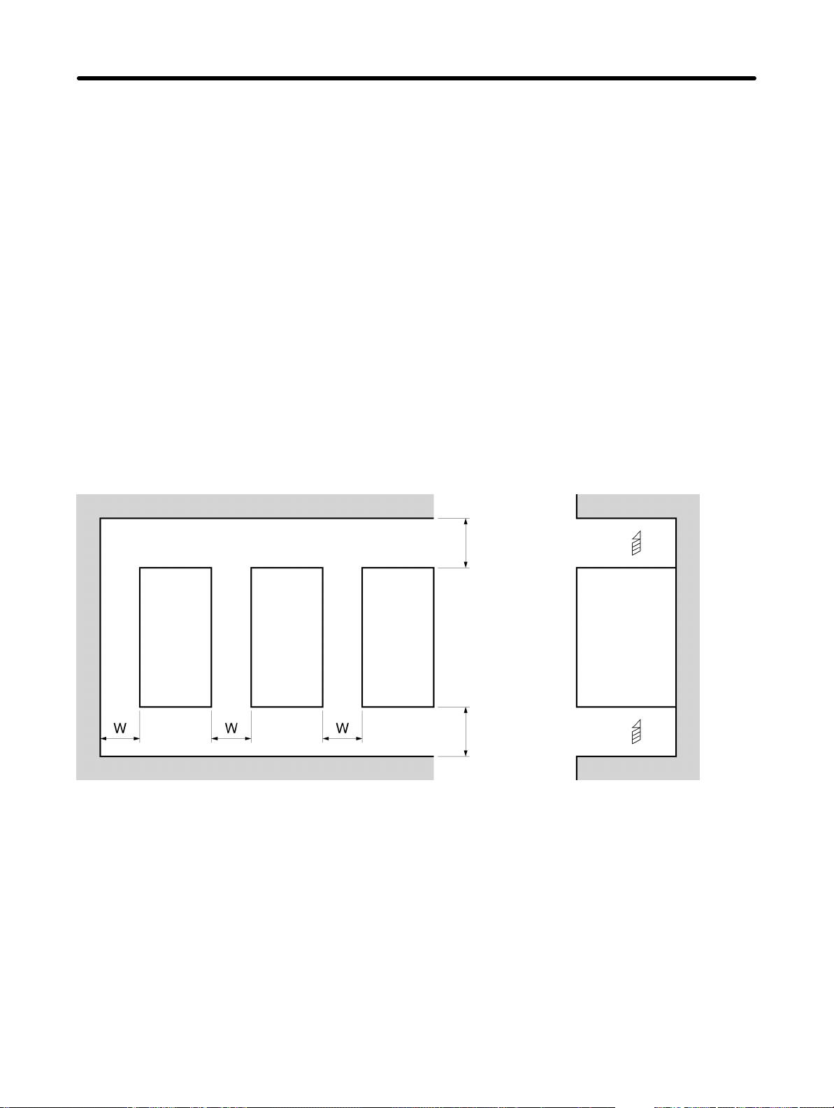
• When installing the Inverter, always provide the following clearances to allow normal heat dissipation
from the Inverter.
W = 30 mm min.
Inverter
100 mm min. Air
SideInverter Inverter
100 mm min. Air
H Ambient Temperature Control
• To enhance operation reliability, the Inverter should be installed in an environment free from extreme
temperature changes.
• If the Inverter is installed in an enclosed environment such as a box, use a cooling fan or air conditioner
to maintain the internal air temperature below 50°C.
The life of the built-in electrolytic capacitors of the Inverter is prolonged by maintaining the internal air
temperature as low as possible.
• The surface temperature of the Inverter may rise approximately 30°C higher than the ambient temperature. Be sure to keep away equipment and wires from the Inverter as far as possible if the equipment
and wires are easily influenced by heat.
2-5
Page 31

Design Chapter 2
H Protecting Inverter from Foreign Matter during Installation
• Place a cover over the Inverter during installation to shield it from metal power produced by drilling.
Upon completion of installation, always remove the cover from the Inverter. Otherwise, ventilation will
be affected, causing the Inverter to overheat.
2-6
Page 32

Design Chapter 2
2-2 Wiring
WARNING Wiring must be performed only after confirming that the power supply has been
!
turned OFF. Not doing so may result in electrical shock.
WARNING Wiring must be performed by authorized personnel. Not doing so may result in
!
electrical shock or fire.
WARNING Be sure to confirm operation only after wiring the emergency stop circuit. Not doing
!
so may result in injury.
WARNING Always connect the ground terminals to a ground of 100 Ω or less for the 200-V AC
!
class, or 10 Ω or less for the 400-V AC class. Not connecting to a proper ground may
result in electrical shock.
Caution Install external breakers and take other safety measures against short-circuiting in
!
external wiring. Not doing so may result in fire.
Caution Confirm that the rated input voltage of the Inverter is the same as the AC power sup-
!
ply voltage. An incorrect power supply may result in fire, injury, or malfunction.
Caution Connect the Braking Resistor and Braking Resistor Unit as specified in the manual.
!
Not doing so may result in fire.
Caution Be sure to wire correctly and securely. Not doing so may result in injury or damage to
!
the product.
Caution Be sure to firmly tighten the screws on the terminal block. Not doing so may result in
!
fire, injury, or damage to the product.
Caution Do not connect an AC power to the U, V, or W output. Doing so may result in damage
!
to the product or malfunction.
2-7
Page 33
Design Chapter 2
2-2-1 Removing and Mounting the Covers
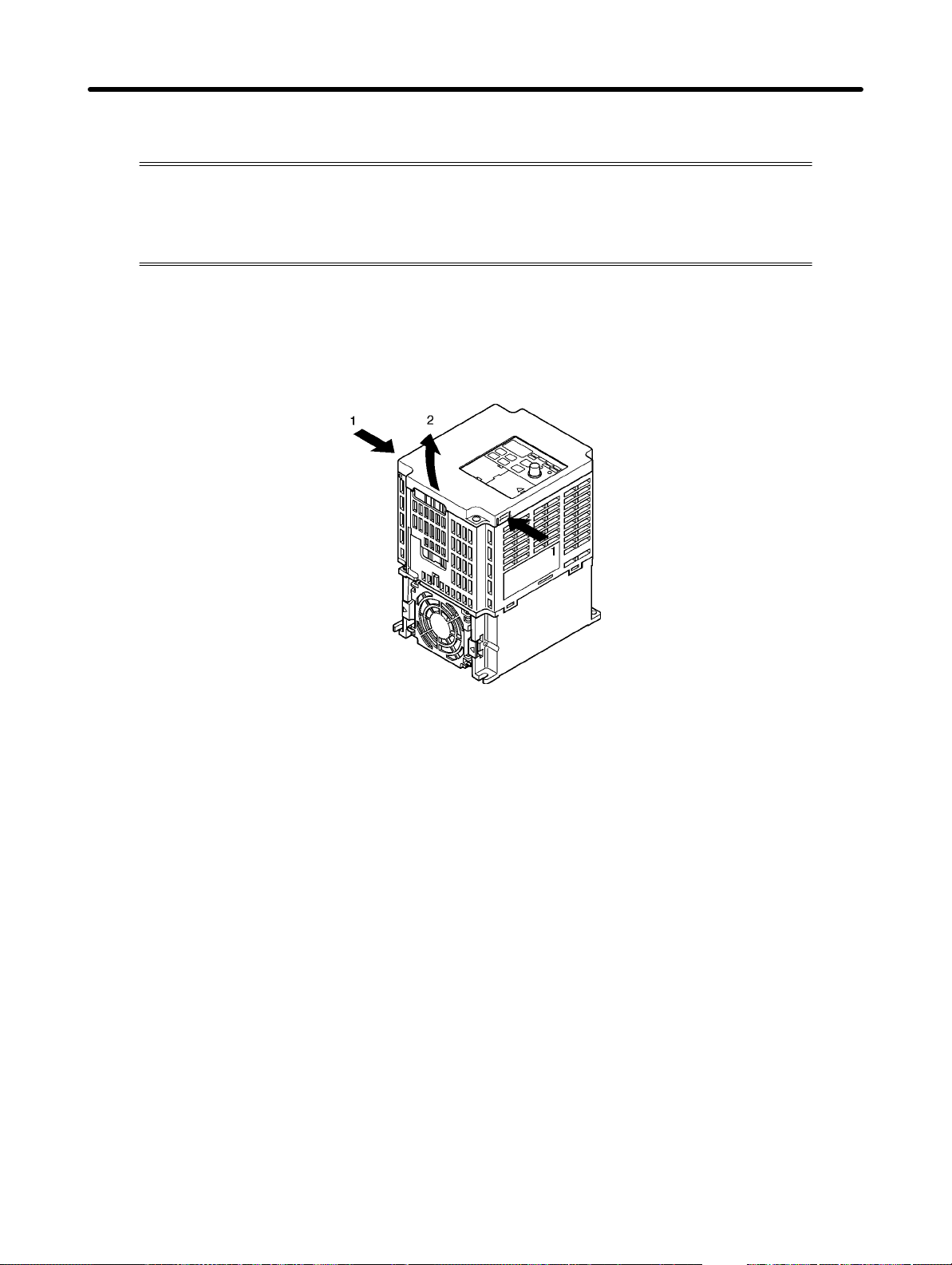
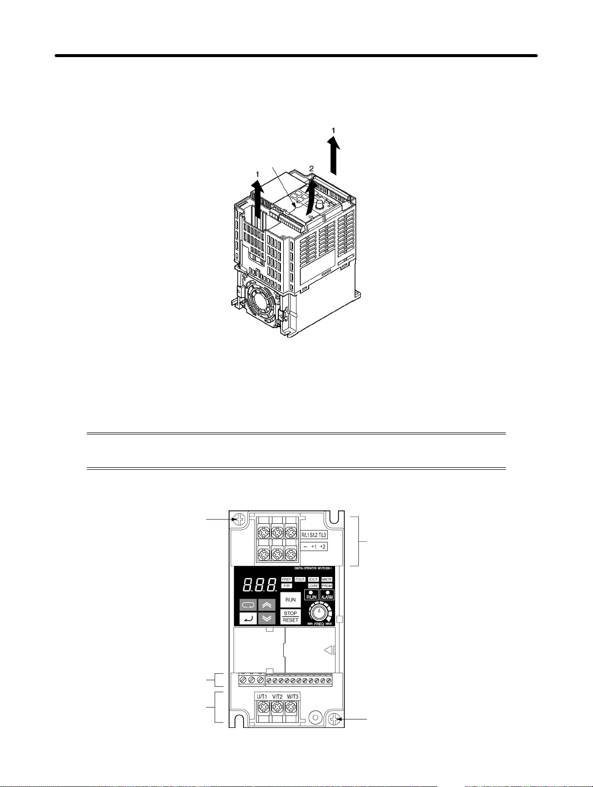
It is necessary to remove the front cover, optional cover, top protection cover, and the
bottom protection cover from the Inverter to wire the terminal block.
Follow the instructions below to remove the covers from the Inverter.
To mount the covers, take the opposite steps.
H Removing the Front Cover
• Loosen the front cover mounting screws with a screwdriver.
• Press the left and right sides of the front cover in the arrow 1 directions and lift the bottom of the cover in
the arrow 2 direction to remove the front cover as shown in the following illustration.
H Removing the Top and Bottom Protection Covers and Optional Cover
D Removing the Top and Bottom Protection Covers
• After removing the front cover, pull the top and bottom protection covers in the arrow 1 directions.
2-8
Page 34
Design Chapter 2
D Removing the Optional Cover
• After removing the front cover, lift the optional cover in the arrow 2 direction based on position A as a
fulcrum.
Position A
Note The front cover functions as a terminal cover. The Digital Operator cannot be removed.
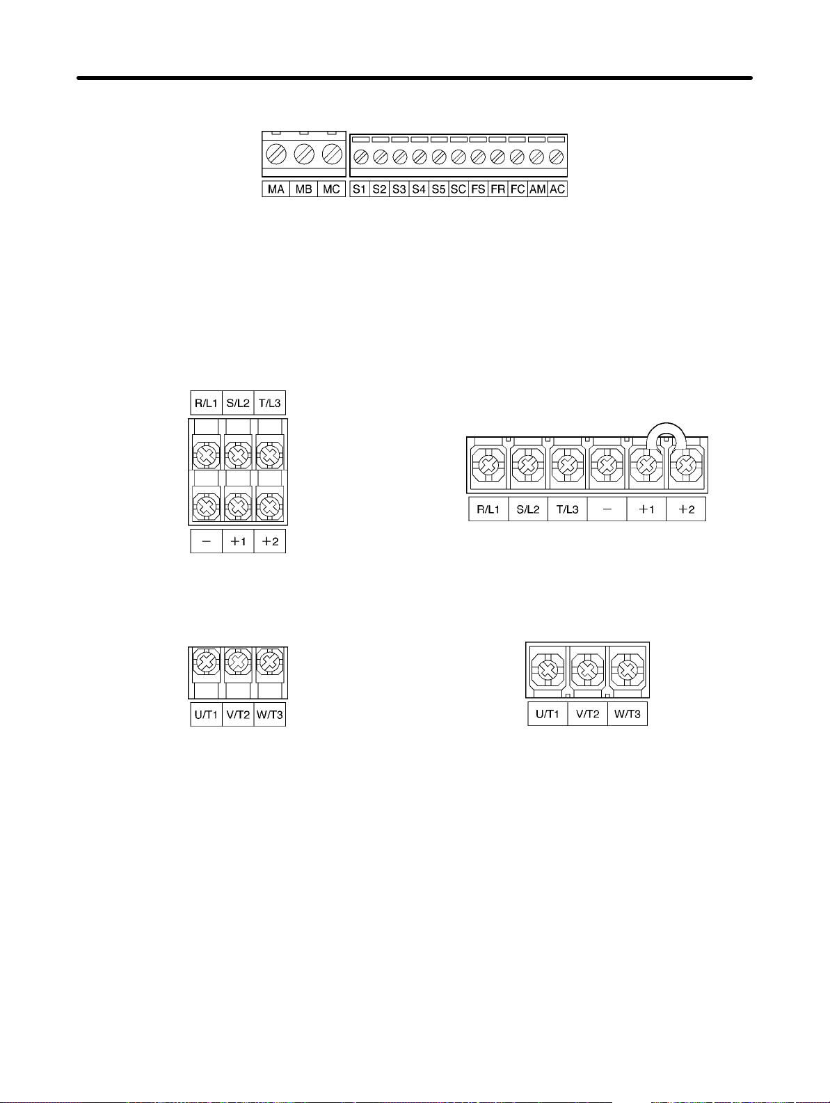
2-2-2 Terminal Block
Before wiring the terminal block, be sure to remove the front cover, top protection cover,
and the bottom protection cover.
H Position of Terminal Block
Ground terminal
Main circuit input terminals
Control circuit terminals
Main circuit output terminals
Ground terminal
2-9
Page 35
Design Chapter 2
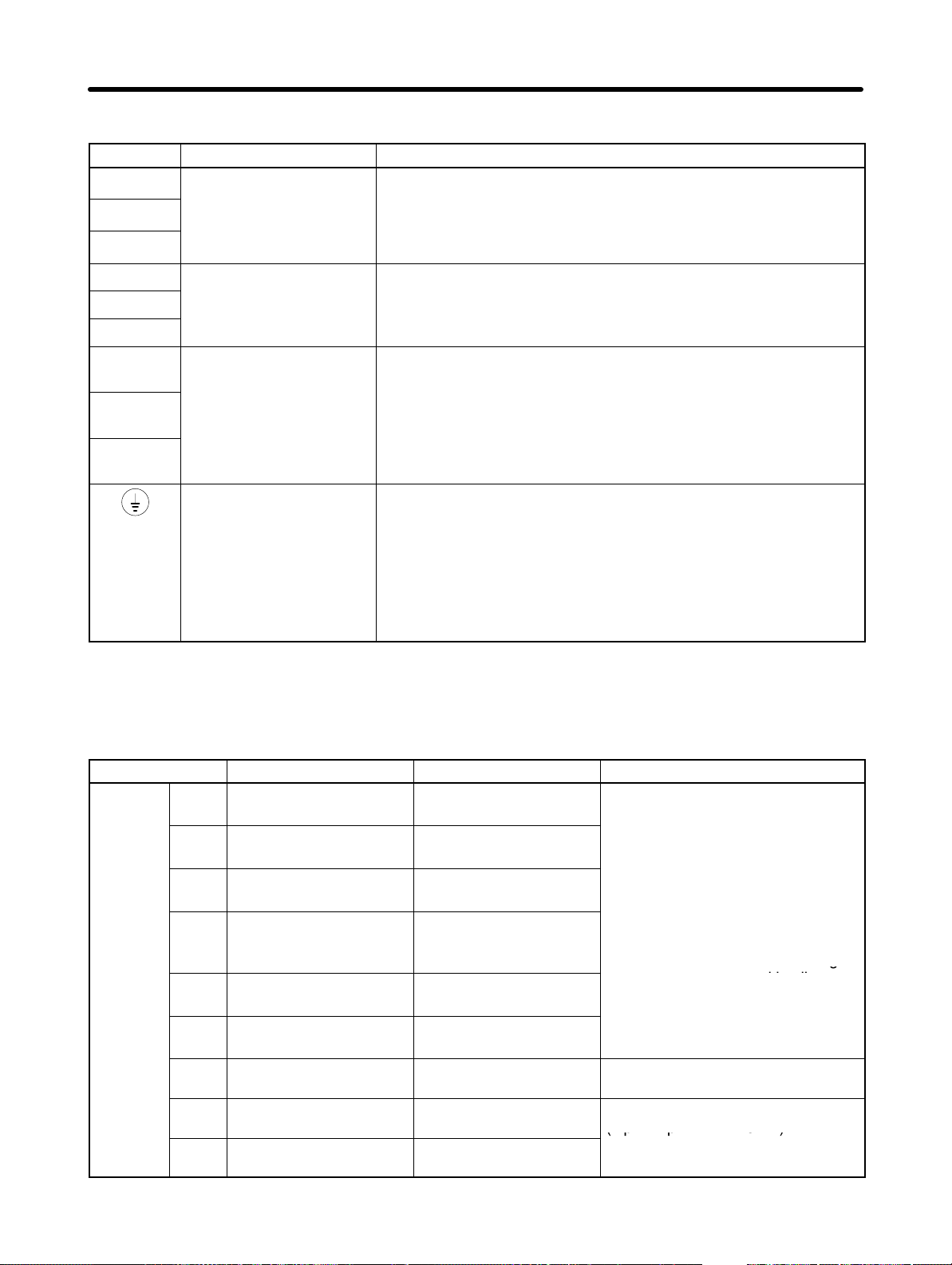
H Arrangement of Control Circuit Terminals
H Arrangement of Main Circuit Terminals
D 3G3JV-A2001 to 3G3JV-A2007
3G3JV-AB001 to 3G3JV-AB004
Main Circuit Input Terminals
(Upper Side)
Main Circuit Output Terminals
(Lower Side)
D 3G3JV-A2015 to 3G3JV-A2037
3G3JV-AB007 to 3G3JV-AB015
3G3JV-A4002 to 3G3JV-A4037
Main Circuit Input Terminals
(Upper Side)
Main Circuit Output Terminals
(Lower Side)
2-10
Page 36
terminals
3G3JV-A4j: 3-phase 380 to 460 V AC
3G3JV-ABj: 3-ph
200 to 240 V AC
DC
+1 and –:
(Terminal +1 is a positive terminal.)
external power supply is
g
PNP
t
(p p 0 )
Design Chapter 2
H Main Circuit Terminals
Symbol Name Description
R/L1
S/L2
T/L3
U/T1
V/T2
W/T3
+1
+2
–
Power supply input
Motor output terminals 3-phase power supply output for driving motors.
Connection terminals +1
and +2:
reactor connection
terminals
–
DC power supply input
terminals
Ground terminal Be sure to ground the terminal under the following conditions.
3G3JV-A2j: 3-phase 200 to 230 V AC
3G3JV-ABj: Single-phase 200 to 240 V AC
-
Note Connect single-phase input to terminals R/L1 and S/L2.
3G3JV-A2j: 3-phase 200 to 230 V AC
3G3JV-A4j: 3-phase 380 to 460 V AC
Connect the DC reactor for suppressing harmonics to terminals +1
and +2.
When driving the Inverter with DC power, input the DC power to
terminals +1 and –.
3G3JV-A2j: Ground at a resistance of 100 Ω or less.
3G3JV-ABj: Ground at a resistance of 100 Ω or less.
3G3JV-A4j: Ground at a resistance of 10 Ω or less, and connect
to the power supply’s neutral phase to conform to EC Directives.
Note Be sure to connect the ground terminal directly to the
-
ase
motor frame ground.
Note The maximum output voltage corresponds to the power supply input voltage of the Inverter.
H Control Circuit Terminals
Symbol Name Function Signal level
Input
S1 Forward/Stop Forward at ON. Stops at
OFF.
S2 Multi-function input 1
(S2)
S3 Multi-function input 2
(S3)
S4 Multi-function input 3
(S4)
S5 Multi-function input 4
(S5)
SC Sequence input com-
mon
FS Frequency reference
power supply
FR Frequency reference in-
put
FC Frequency reference
common
Set by parameter n36
(Reverse/Stop)
Set by parameter n37
(Fault reset)
Set by parameter n38
(External fault: Normally
open)
Set by parameter n39
(Multi-step reference 1)
Common for S1 through
S5
DC power supply for frequency reference use
Input terminal for frequency reference use
Common for frequency
reference use
Photocoupler
8 mA at 24 V DC
Note NPN is the default setting
for these terminals. Wire
them by providing a
common ground. No
required. To provide an
external power supply and
wire the terminals through
a common positive line,
however, set the SW7 to
and make sure tha
the power supply is at
24 V DC ±10%.
20 mA at 12 V DC
0 to 10 V DC
(input impedance: 20 kΩ)
2-11
Page 37
(g g)
30 C
Design Chapter 2
Symbol Signal levelFunctionName
Output
MA Multi-function contact
output (Normally open)
MB Multi-function contact
output (Normally closed)
MC Multi-function contact
output common
AM Analog monitor output Set by parameter n44
AC Analog monitor output
common
Note 1. Depending on the parameter settings, various functions can be selected for multi-function in-
puts and multi-function contacts outputs.
Note 2. Functions in parentheses are default settings.
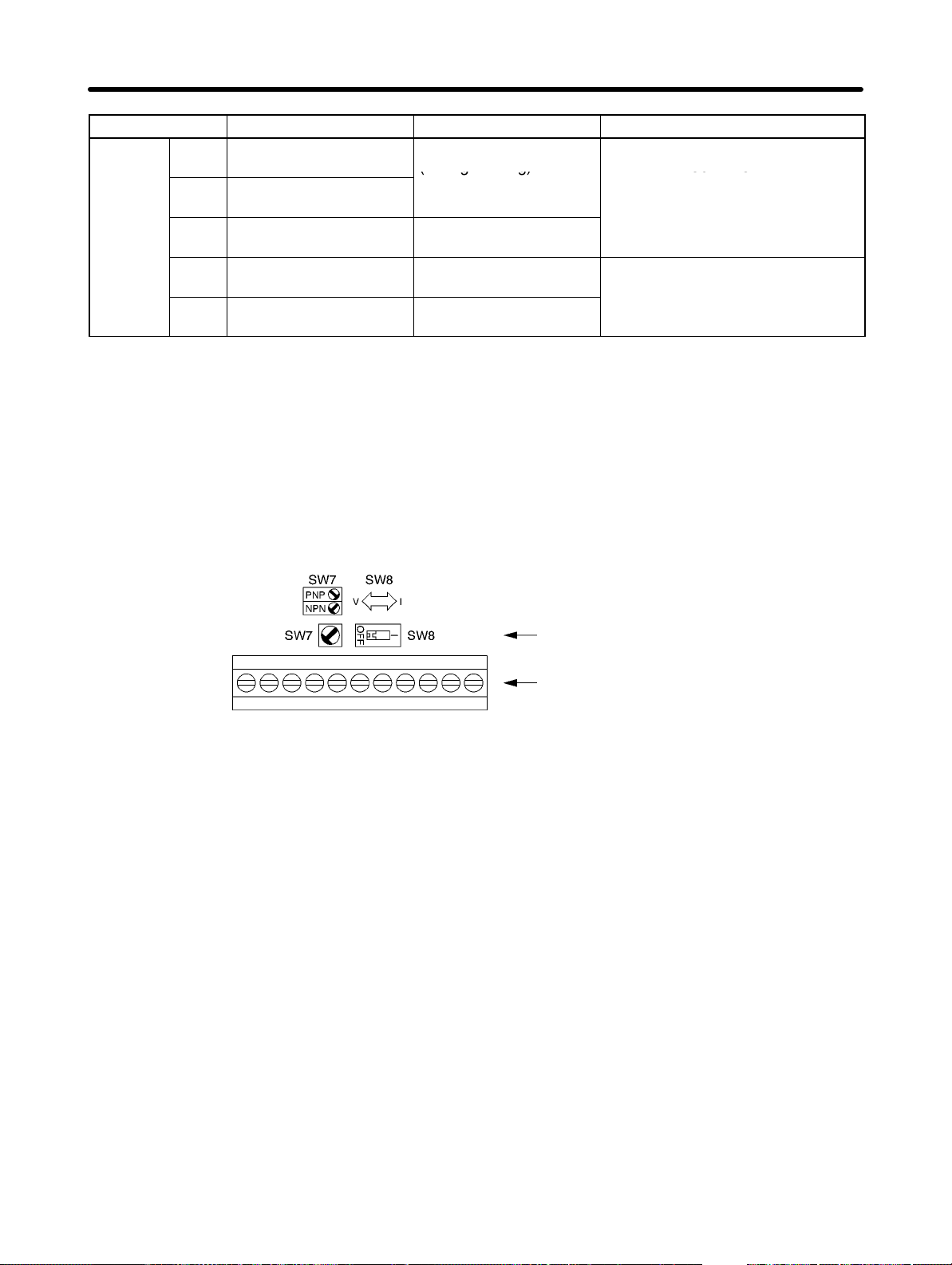
H Selecting Input Method
• Switches SW7 and SW8, both of which are located above the control circuit terminals, are used for
input method selection.
Remove the front cover and optional cover to use these switches.
Set by parameter n40
(during running)
Common for MA and
MB use
(Output frequency)
Common for AM use
Relay output
1 A max. at 30 V DC
1 A max. at 250 V AC
2 mA max. at 0 to 10 V DC
Selector
Control circuit terminal
block
2-12
Page 38
Design Chapter 2
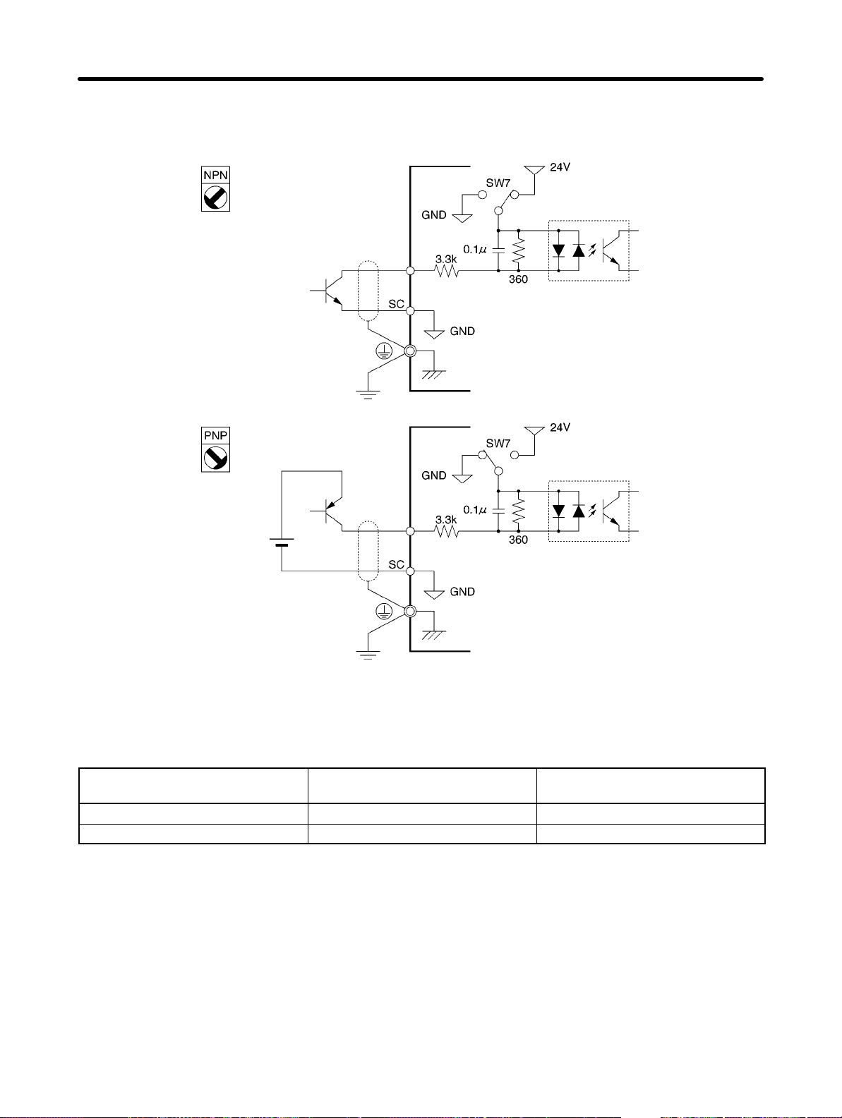
D Selecting Sequence Input Method
• By using SW7, NPN or PNP input can be selected as shown below.
S1 to 5
S1 to 5
24 V DC
(±10%)
D Selecting Frequency Reference Input Method
• By using SW8, frequency reference voltage or current input can be selected.
Parameter settings are required together with the selection of the frequency reference input method.
Frequency reference input
method
Voltage input V (OFF) Set value 2
Current input I (ON) Set value 3 or 4
SW8 setting Frequency reference selection
(parameter n03)
2-13
Page 39
Design Chapter 2
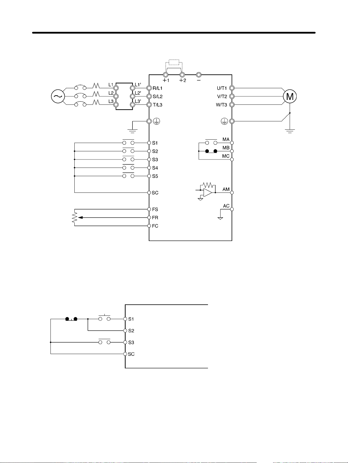
2-2-3 Standard Connections
DC reactor
(optional)
Noise Filter
3-phase 200 V AC
Single-phase 200 V AC
(see note 1)
3-phase 400 V AC
Forward/Stop
Multi-function input 1 (S2)
Multi-function input 2 (S3)
Multi-function input 3 (S4)
Multi-function input 4 (S5)
Multi-function contact output
NO
NC
Common
Sequence input common
Frequency reference power
supply 20 mA at +12 V
FREQ
adjuster
(2 kΩ, 1/4 W min.)
Frequency reference input
Frequency reference common
Analog monitor output
Analog monitor output common
Note 1. Connect single-phase 200 V AC to terminals R/L1 and S/L2 of the 3G3JV-ABj.
Note 2. The braking resistor cannot be connected because no braking transistor is incorporated.
D Example of 3-wire Sequence Connections
Stop
switch
(NC)
RUN
switch
(NO)
Direction switch
RUN input (Operates with the stop switch and RUN switch closed.)
Stop input (Stops with the stop switch opened.)
Forward/Stop reference (Forward with the direction switch opened
and reverse with the direction switch closed.)
Sequence input common
Note Set parameter n37 for 3-wire sequence input.
2-14
Page 40
Design Chapter 2
2-2-4 Wiring around the Main Circuit
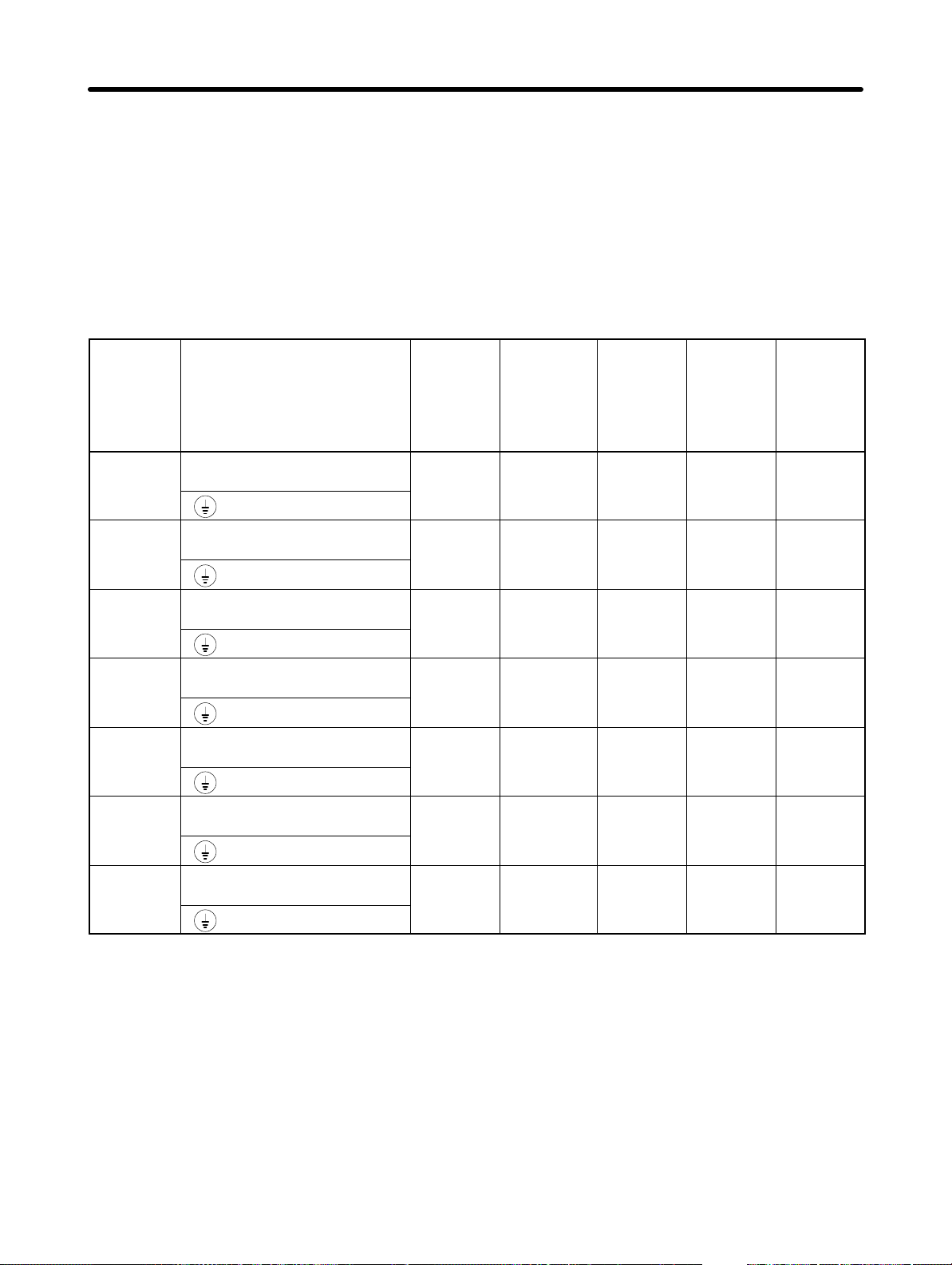
H Wire Size, Terminal Screw, Screw Tightening Torque, and Molded-case
Circuit Breaker Capacities
• For the main circuit and ground, always use 600-V polyvinyl chloride (PVC) cables.
• If any cable is long and may cause voltage drops, increase the wire size according to the cable length.
D 3-phase 200-V AC Model
Model
3G3JV-
A2001
A2002
A2004
A2007
A2015
A2022
Terminal symbol Terminal
R/L1, S/L2, T/L3, –, +1, +2,
U/T1, V/T2, W/T3
R/L1, S/L2, T/L3, –, +1, +2,
U/T1, V/T2, W/T3
R/L1, S/L2, T/L3, –, +1, +2,
U/T1, V/T2, W/T3
R/L1, S/L2, T/L3, –, +1, +2,
U/T1, V/T2, W/T3
R/L1, S/L2, T/L3, –, +1, +2,
U/T1, V/T2, W/T3
R/L1, S/L2, T/L3, –, +1, +2,
U/T1, V/T2, W/T3
Screw
screw
M3.5 0.8 to 1.0 0.75 to 2 2 5
M3.5 0.8 to 1.0 0.75 to 2 2 5
M3.5 0.8 to 1.0 0.75 to 2 2 5
M3.5 0.8 to 1.0 0.75 to 2 2 10
M3.5 0.8 to 1.0 2 to 5.5 2 20
M3.5 0.8 to 1.0 2 to 5.5 3.5 20
tightening
torque
(NSm)
Wire size
2
(mm
)
Recomme
nded wire
size
2
(mm
)
Molded-c
ase
circuit
breaker
capacity
(A)
A2037
R/L1, S/L2, T/L3, –, +1, +2,
U/T1, V/T2, W/T3
M4 1.2 to 1.5 2 to 5.5 5.5 30
2-15
Page 41
Design Chapter 2
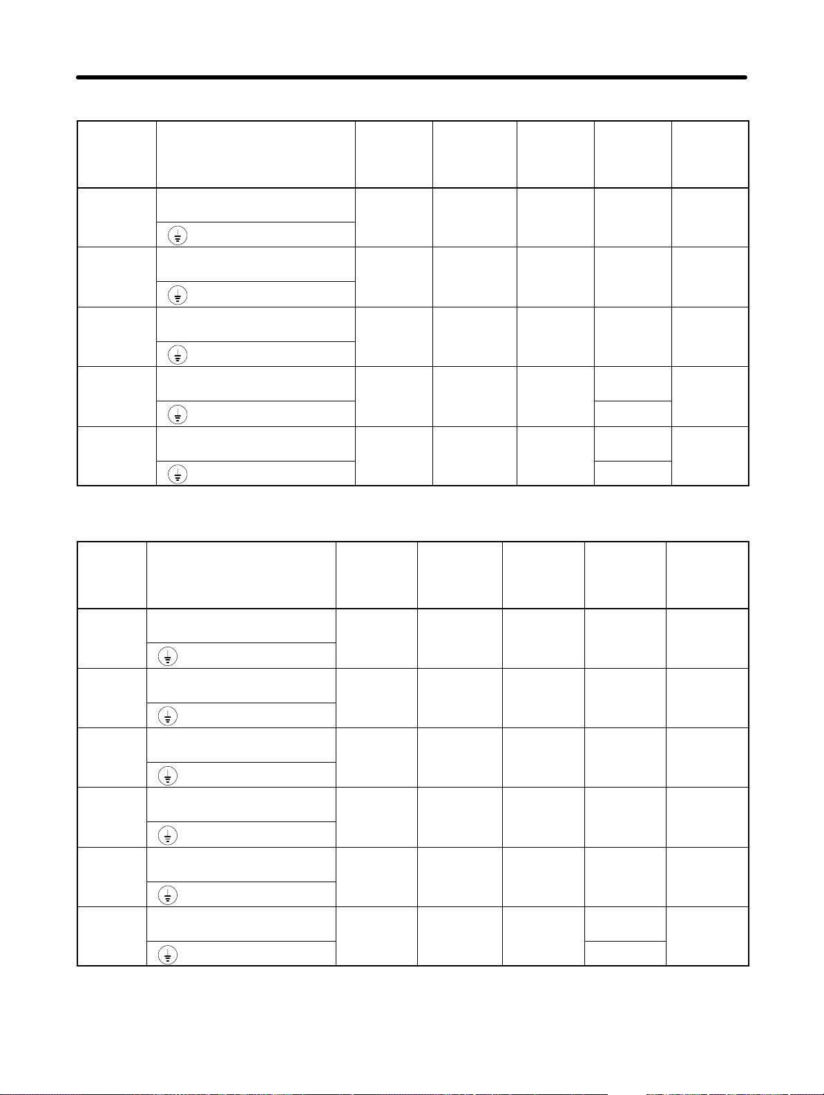
D Single-phase 200-V AC Model
Model
3G3JV-
AB001
AB002
AB004
AB007
AB015
Terminal symbol Terminal
R/L1, S/L2, T/L3, –, +1, +2,
U/T1, V/T2, W/T3
R/L1, S/L2, T/L3, –, +1, +2,
U/T1, V/T2, W/T3
R/L1, S/L2, T/L3, –, +1, +2,
U/T1, V/T2, W/T3
R/L1, S/L2, T/L3, –, +1, +2,
U/T1, V/T2, W/T3
R/L1, S/L2, T/L3, –, +1, +2,
U/T1, V/T2, W/T3
D 3-phase 400-V AC Model
Terminal
screw
M3.5 0.8 to 1.0 0.75 to 2 2 5
M3.5 0.8 to 1.0 0.75 to 2 2 5
M3.5 0.8 to 1.0 0.75 to 2 2 10
M3.5 0.8 to 1.0 2 to 5.5
M3.5 0.8 to 1.0 2 to 5.5
torque
(NSm)
Wire size
2
(mm
)
Recomme
nded wire
size
2
(mm
)
3.5
2
5.5
2
20
20
Circuit
breaker
capacity
(A)
Model
3G3JV-
A4002
A4004
A4007
A4015
A4022
A4037
Terminal symbol Terminal
R/L1, S/L2, T/L3, –, +1, +2,
U/T1, V/T2, W/T3
R/L1, S/L2, T/L3, –, +1, +2,
U/T1, V/T2, W/T3
R/L1, S/L2, T/L3, –, +1, +2,
U/T1, V/T2, W/T3
R/L1, S/L2, T/L3, –, +1, +2,
U/T1, V/T2, W/T3
R/L1, S/L2, T/L3, –, +1, +2,
U/T1, V/T2, W/T3
R/L1, S/L2, T/L3, –, +1, +2,
U/T1, V/T2, W/T3
Terminal
screw
M3.5 0.8 to 1.0 2 to 5.5 2 5
M3.5 0.8 to 1.0 2 to 5.5 2 5
M3.5 0.8 to 1.0 2 to 5.5 2 5
M3.5 0.8 to 1.0 2 to 5.5 2 10
M4 1.2 to 1.5 2 to 5.5 2 10
M4 1.2 to 1.5 2 to 5.5
torque
(NSm)
Wire size
2
(mm
)
Recomme
nded wire
size (mm
2
3.5
2
)
20
Circuit
breaker
capacity
(A)
2-16
Page 42
Design Chapter 2
H Wiring on the Input Side of the Main Circuit
D Installing a Molded-case Circuit Breaker
Always connect the power input terminals (R/L1, S/L2, and T/L3) and power supply via a molded case
circuit breaker (MCCB) suitable to the Inverter.
• Install one MCCB for every Inverter used.
• Choose an appropriate MCCB capacity according to the Circuit breaker capacity column in the table
on the previous page.
• For the MCCB’s time characteristics, be sure to consider the Inverter’s overload protection (one minute at 150% of the rated output current).
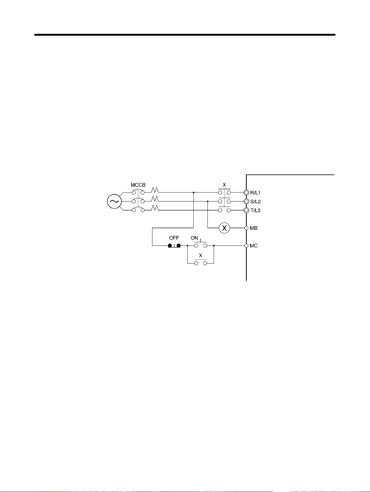
• If the MCCB is to be used in common among multiple Inverters, or other devices, set up a sequence
such that the power supply will be turned off by a fault output, as shown in the following diagram.
Inverter
Power
supply
3-phase/Single-phase
200 V AC
3-phase 400 V AC
Fault output
(NC)
D Installing a Ground Fault Interrupter
Inverter outputs use high-speed switching, so high-frequency leakage current is generated.
In general, a leakage current of approximately 100 mA will occur for each Inverter (when the power
cable is 1 m) and approximately 5 mA for each additional meter of power cable.
Therefore, at the power supply input area, use a special-purpose breaker for Inverters, which detects
only the leakage current in the frequency range that is hazardous to humans and excludes high-frequency leakage current.
• For the special-purpose breaker for Inverters, choose a ground fault interrupter with a sensitivity amperage of at least 10 mA per Inverter.
• When using a general leakage breaker, choose a ground fault interrupter with a sensitivity amperage
of 200 mA or more per Inverter and with an operating time of 0.1 s or more.
D Installing a Magnetic Contactor
If the power supply of the main circuit is to be shut off because of the sequence, a magnetic contactor
can be used instead of a molded-case circuit breaker.
When a magnetic contactor is installed on the primary side of the main circuit to stop a load forcibly,
however, the regenerative braking does not work and the load coasts to a stop.
2-17
Page 43
Design Chapter 2
• A load can be started and stopped by opening and closing the magnetic contactor on the primary side.
Frequently opening and closing the magnetic contactor, however, may cause the Inverter to break
down. In order not to shorten the service life of the Inverter’s internal relays and electrolytic capacitors,
it is recommended that the magnetic contactor is used in this way no more than once every 30 minutes.
• When the Inverter is operated with the Digital Operator, automatic operation cannot be performed after recovery from a power interruption.
D Connecting Input Power Supply to the Terminal Block
Input power supply can be connected to any terminal on the terminal block because the phase sequence of input power supply is irrelevant to the phase sequence (R/L1, S/L2, and R/L3).
D Installing an AC Reactor
If the Inverter is connected to a large-capacity power transformer (660 kW or more) or the phase advance capacitor is switched, an excessive peak current may flow through the input power circuit, causing the converter unit to break down.
To prevent this, install an optional AC reactor on the input side of the Inverter.
This also improves the power factor on the power supply side.
D Installing a Surge Absorber
Always use a surge absorber or diode for the inductive loads near the Inverter. These inductive loads
include magnetic contactors, electromagnetic relays, solenoid valves, solenoid, and magnetic brakes.
D Installing a Noise Filter on the Power Supply Side
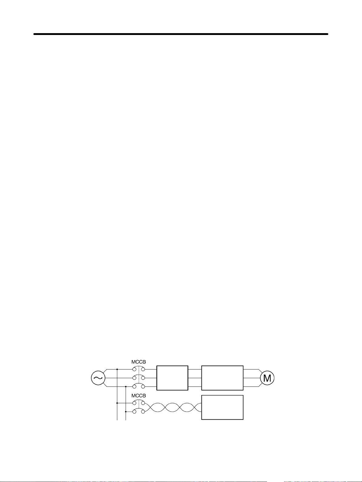
The Inverter’s outputs uses high-speed switching, so noise may be transmitted from the Inverter to the
power line and adversely effect other devices in the vicinity. It is recommended that a Noise Filter be
installed at the Power Supply to minimize noise transmission. Noise will also be reduced from the power
line to the Inverter.
Wiring Example 1
Input Noise Filters
Simple Input Noise Filter: 3G3EV-PLNFDj
Power
supply
EMC-conforming Input Noise Filter: 3G3JV-PRSj
3G3JV
Noise
Filter
SYSDRIVE
Programmable
Controller
Note Use a Noise Filter designed for the Inverter. A general-purpose Noise Filter will be less effective
and may not reduce noise.
2-18
Page 44
Design Chapter 2
H Wiring on the Output Side of the Main Circuit
D Connecting the Terminal Block to the Load
Connect output terminals U/T1, V/T2, and W/T3 to motor lead wires U, V, and W.
Check that the motor rotates forward with the forward command. Switch over any two of the output terminals to each other and reconnect if the motor rotates in reverse with the forward command.
D Never Connect a Power Supply to Output Terminals
Never connect a power supply to output terminals U/T1, V/T2, or W/T3.
If voltage is applied to the output terminals, the internal circuit of the Inverter will be damaged.
D Never Short or Ground Output Terminals
If the output terminals are touched with bare hands or the output wires come into contact with the
Inverter casing, an electric shock or grounding will occur. This is extremely hazardous.
Also, be careful not to short the output wires.
D Do not Use a Phase Advancing Capacitor or Noise Filter
Never connect a phase advance capacitor or LC/RC Noise Filter to the output circuit.
Doing so will result in damage to the Inverter or cause other parts to burn.
D Do not Use an Electromagnetic Switch of Magnetic Contactor
Do not connect an electromagnetic switch of magnetic contactor to the output circuit.
If a load is connected to the Inverter during running, an inrush current will actuate the overcurrent protective circuit in the Inverter.
D Installing a Thermal Relay
The Inverter has an electronic thermal protection function to protect the motor from overheating. If, however, more than one motor is operated with one inverter or a multi-polar motor is used, always install a
thermal relay (THR) between the Inverter and the motor and set n33 to 2 (no thermal protection).
In this case, program the sequence so that the magnetic contactor on the input side of the main circuit is
turned off by the contact of the thermal relay.
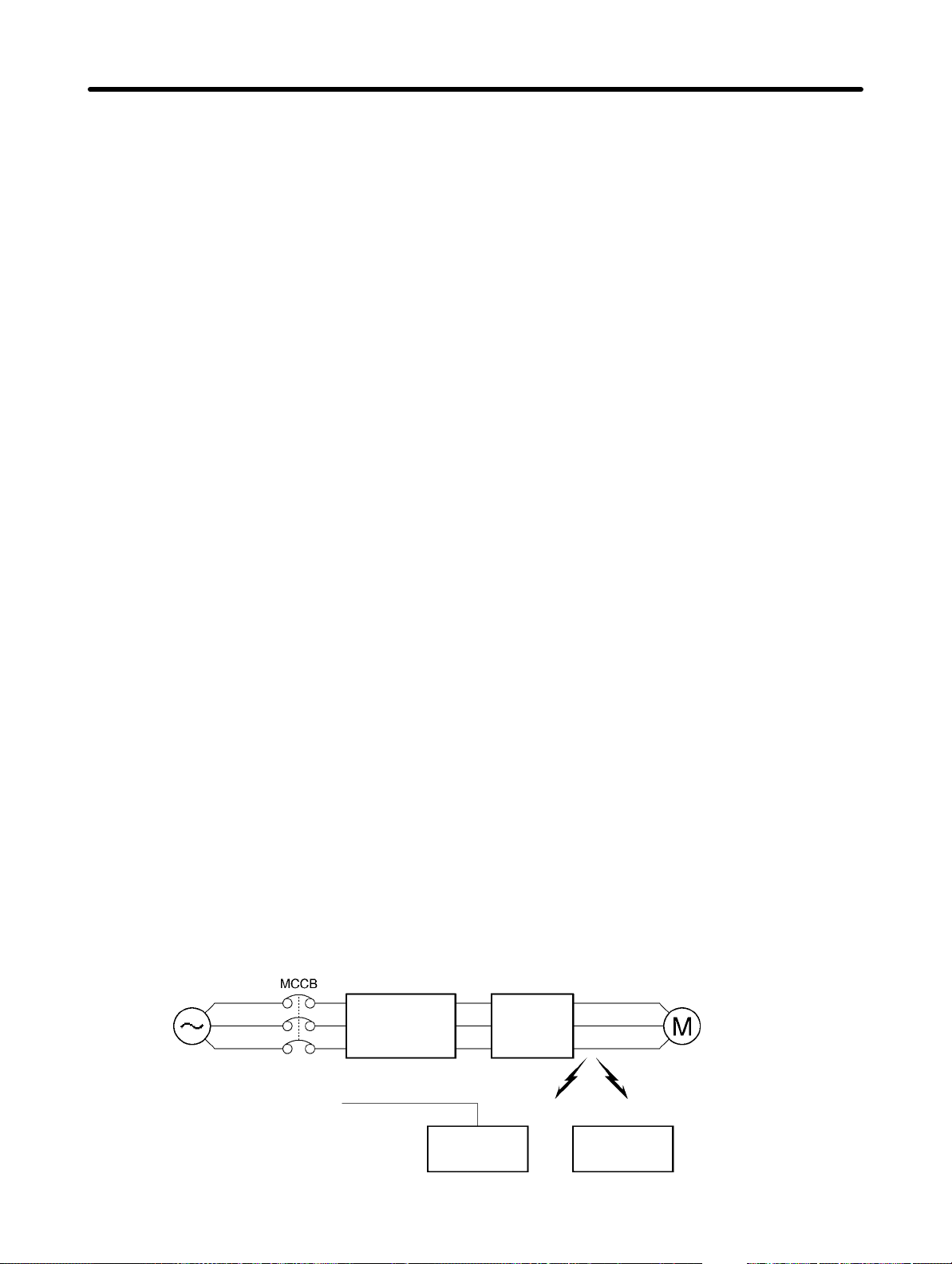
D Installing a Noise Filter on the Output Side
Connect a Noise Filter to the output side of the Inverter to reduce radio noise and induction noise.
Power
supply
3G3JV
SYSDRIVE
3G3IV-PLF
Noise
Filter
Signal line
Induction noise Radio noise
Controller
AM radio
2-19
Page 45

Design Chapter 2
Induction Noise: Electromagnetic induction generates noise on the signal line, causing the con-
troller to malfunction.
Radio Noise: Electromagnetic waves from the Inverter and cables cause the broadcasting ra-
dio receiver to make noise.
D Countermeasures against Induction Noise
As described previously, a Noise Filter can be used to prevent induction noise from being generated on
the output side. Alternatively, cables can be routed through a grounded metal pipe to prevent induction
noise. Keeping the metal pipe at least 30 cm away from the signal line considerably reduces induction
noise.
Power supply
3G3JV
SYSDRIVE
Signal line
Metal pipe
30 cm min.
Controller
D Countermeasures against Radio Interference
Radio noise is generated from the Inverter as well as the input and output lines. To reduce radio noise,
install Noise Filters on both input and output sides, and also install the Inverter in a totally enclosed steel
box.
The cable between the Inverter and the motor should be as short as possible.
Steel box
Power supply
3G3JV
Metal pipe
Noise
Filter
SYSDRIVE
Noise
Filter
D Cable Length between Inverter and Motor
As the cable length between the Inverter and the motor is increased, the floating capacity between the
Inverter outputs and the ground is increased proportionally. The increase in floating capacity at the
Inverter outputs causes the high-frequency leakage current to increase, and this may adversely affect
peripheral devices and the current detector in the Inverter’s output section. To prevent this from occurring, use a cable of no more than 100 meters between the Inverter and the motor. If the cable must be
longer than 100 meters, take measures to reduce the floating capacity by not wiring in metallic ducts, by
using separate cables for each phase, etc.
2-20
Page 46

Design Chapter 2
Also, adjust the carrier frequency (set in n46) according to the cable length between the Inverter and the
motor, as shown in the following table.
Cable length 50 m or less 100 m or less More than 100 m
Carrier frequency 10 kHz max. 5 kHz max. 2.5 kHz
Note Single-phase motors cannot be used.
The Inverter is not suited for the variable speed control of single-phase motors.
The rotation direction of a single-phase motor is determined by the capacitor starting method or
phase-splitting starting method to be applied when starting the motor.
In the capacitor starting method, however, the capacitor may be damaged by a sudden electric
discharge of the capacitor caused by the output of the Inverter. On the other hand, the starting coil
may burn in the phase-splitting starting method because the centrifugal switch does not operate.
H Ground Wiring
• Always use the ground terminal with the following ground resistance:
200-V Inverter: 100 Ω or less
400-V Inverter: separate ground,10 Ω or less
• Do not share the ground wire with other devices such as welding machines or power tools.
• Always use a ground wire that complies with technical standards on electrical equipment and mini-
mize the length of the ground wire.
Leakage current flows through the Inverter. Therefore, if the distance between the ground electrode
and the ground terminal is too long, the potential on the ground terminal of the Inverter will become
unstable.
2-21
Page 47
Design Chapter 2
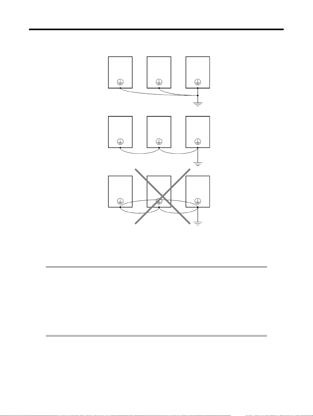
• When using more than one Inverter, be careful not to loop the ground wire.
H Countermeasures against Harmonics
With the continuing development of electronics, the generation of harmonics from industrial machines has been causing problems recently.
The Ministry of International Trade and Industry provided some guidelines in September
1994 for the suppression of harmonics from electrical household appliances and electrical equipment in Japan. Since then, the problem has been drawing considerable attention.
Refer to the following information for the definition of harmonics (i.e., harmonic currents
with voltages) and countermeasures against the generation of harmonics from the
Inverter.
D Harmonics
Definition
Harmonics consist of electric power produced from AC power and alternating at frequencies that are
integral multiples of the frequency of the AC power.
2-22
Page 48
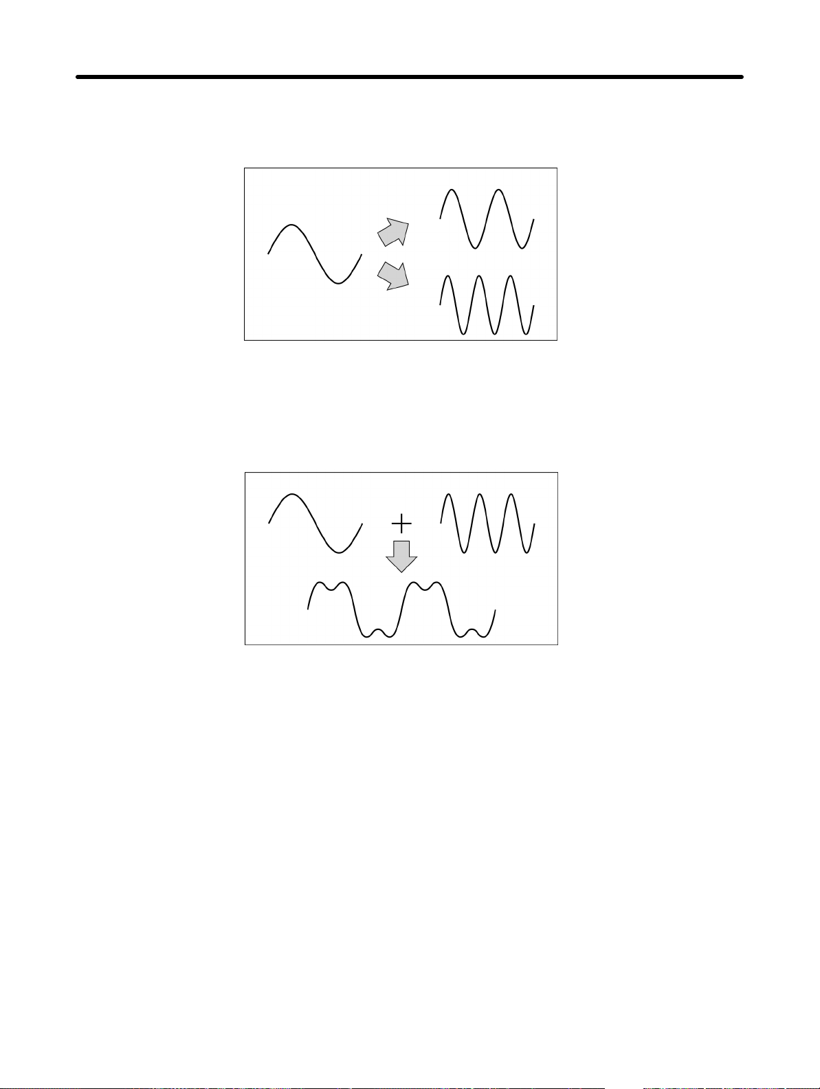
Design Chapter 2
The following frequencies are harmonics of a 60- or 50-Hz commercial power supply.
Second harmonic: 120 (100) Hz
Third harmonic: 180 (150) Hz
Second harmonic (120 Hz)
Basic frequency (60 Hz)
Third harmonic (180 Hz)
Problems Caused by Harmonics Generation
The waveform of the commercial power supply will be distorted if the commercial power supply contains
excessive harmonics. Machines with such a commercial power supply will malfunction or generate excessive heat.
Basic frequency (60 Hz) Third harmonic (180 Hz)
Distorted current wave
form
D Causes of Harmonics Generation
• Usually, electric machines have built-in circuitry that converts commercial AC power supply into DC
power.
Such AC power, however, contains harmonics due to the difference in current flow between DC and
AC.
Obtaining DC from AC Using Rectifiers and Capacitors
DC voltage is obtained by converting AC voltage into a pulsating one-side voltage with rectifiers and
smoothing the pulsating one-side voltage with capacitors. Such AC current, however, contains harmonics.
2-23
Page 49
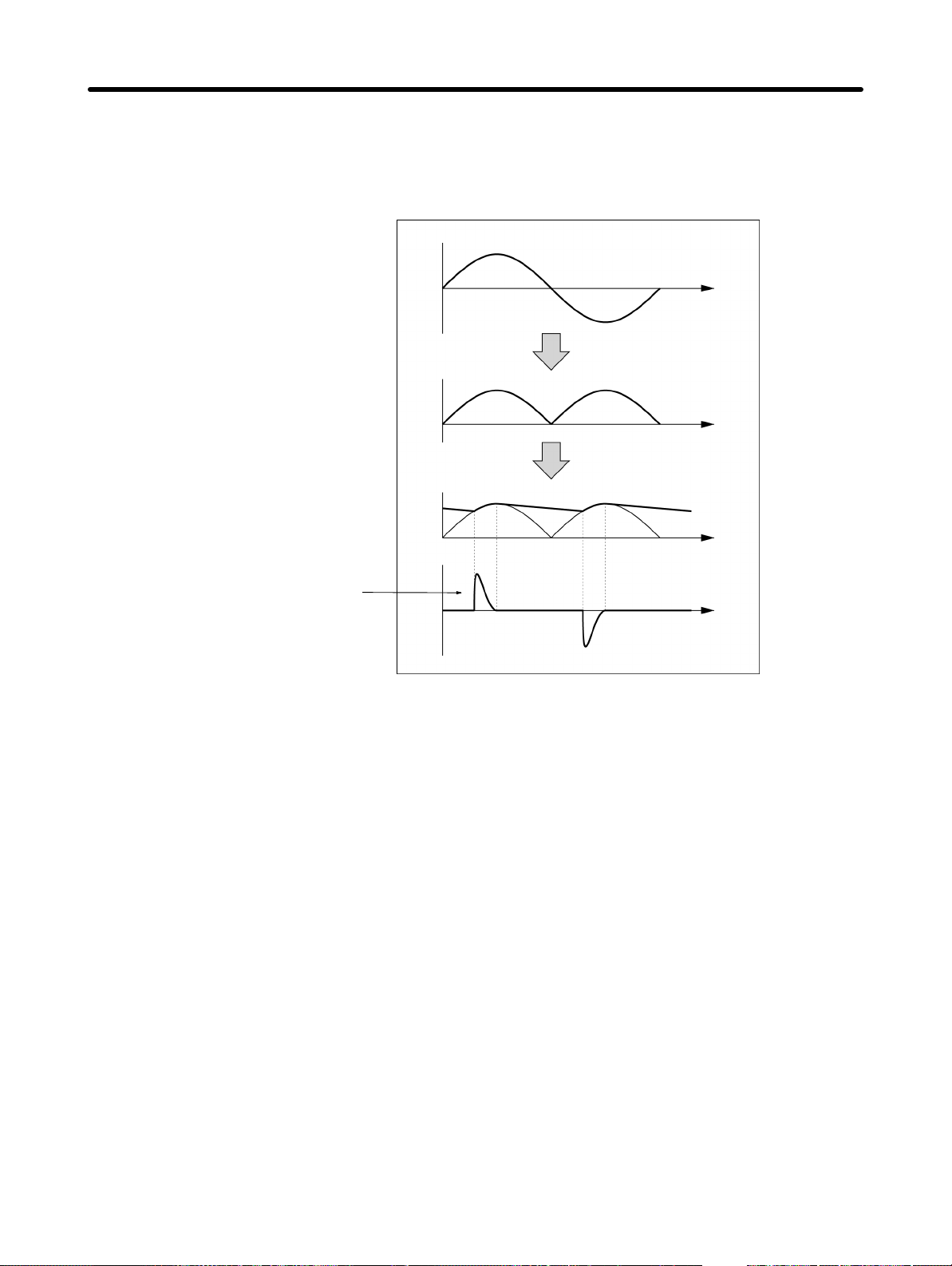
Design Chapter 2
Inverter
The Inverter as well as normal electric machines has an input current containing harmonics because
the Inverter converts AC into DC. The output current of the Inverter is comparatively high. Therefore, the
ratio of harmonics in the output current of the Inverter is higher than that of any other electric machine.
Voltage
Time
Rectified
Voltage
Time
Smoothed
Voltage
A current flows into the
capacitors. The current is
different from the voltage
in waveform.
Current
Time
Time
2-24
Page 50
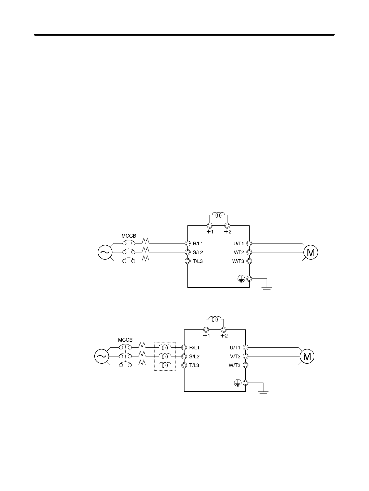
Design Chapter 2
D Countermeasures with Reactors against Harmonics Generation
DC/AC Reactors
The DC reactor and AC reactor suppress harmonics and currents that change suddenly and greatly.
The DC reactor suppresses harmonics better than the AC reactor. The DC reactor used with the AC
reactor suppresses harmonics more effectively.
The input power factor of the Inverter is improved by suppressing the harmonics of the input current of
the Inverter.
Connection
Connect the DC reactor to the internal DC power supply of the Inverter after shutting off the power supply to the Inverter and making sure that the charge indicator of the Inverter turns off.
Do not touch the internal circuitry of the Inverter in operation, otherwise an electric shock or burn injury
may occur.
Wiring Method
• With DC Reactor
Power supply
3-phase 200 V AC
Single-phase 200 V AC
3-phase 400 V AC
• With DC and AC Reactors
Power supply
3-phase 200 V AC
Single-phase 200 V AC
3-phase 400 V AC
DC reactor
(optional)
AC reactor
(optional)
DC reactor
(optional)
SYSDRIVE
3G3JV
SYSDRIVE
3G3JV
2-25
Page 51
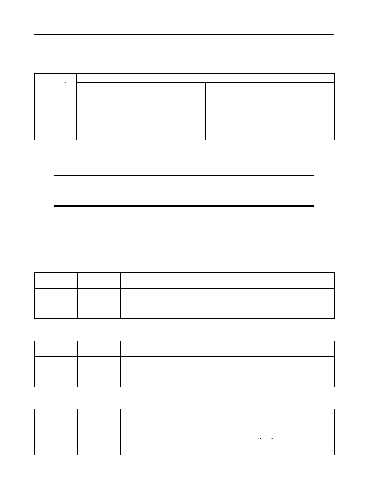
py y
Design Chapter 2
Reactor Effects
Harmonics are effectively suppressed when the DC reactor is used with the AC reactor as shown in the
following table.
Harmonics
suppression
method
No reactor 65 41 8.5 7.7 4.3 3.1 2.6 1.8
AC reactor 38 14.5 7.4 3.4 3.2 1.9 1.7 1.3
DC reactor 30 13 8.4 5 4.7 3.2 3.0 2.2
DC and AC
reactors
5th har-
monic
28 9.1 7.2 4.1 3.2 2.4 1.6 1.4
7th har-
monic
Harmonic generation rate (%)
11th har-
monic
13th har-
monic
17th har-
monic
19th har-
monic
23rd har-
monic
2-2-5 Wiring Control Circuit Terminals
A control signal line must be 50 m maximum and separated from power lines.
The frequency reference must be input into the Inverter through shielded, twisted-pair
wires.
H Wiring of Control I/O Terminals
Wire each control I/O terminal under the following conditions.
D Wires and Tightening Torque
25th har-
monic
Multi-function Contact Output (MA, MB, and MC)
Terminal
screw size
M3 0.5 to 0.6
Tightening
torque NSm
Wire Wire size Recommend
ed wire size
Single wire 0.5 to 1.25
(20 to 16)
Stranded
wire
0.5 to 1.25
(20 to 16)
0.75 (18) Cable with polyethylene
Cable
sheath
Sequential Input (S1 through S5 and SC) and Analog Monitor Output (AM or AC)
Terminal
screw size
M2 0.22 to 0.25
Tightening
torque NSm
Wire Wire size Recommend
ed wire size
Single wire 0.5 to 1.25
(20 to 16)
Stranded
wire
0.5 to 0.75
(20 to 18)
0.75 (18) Cable with polyethylene
Cable
sheath
Frequency Reference Input (FR, FS, and FC)
Terminal
screw size
M2 0.22 to 0.25
Tightening
torque NSm
Wire Wire size Recommend
ed ire size
Single wire 0.5 to 1.25
(20 to 16)
Stranded
wire
0.5 to 0.75
(20 to 18)
0.75 (18) Special cable with
Cable
polyethylene sheath and
shield for measurement use
2-26
Page 52
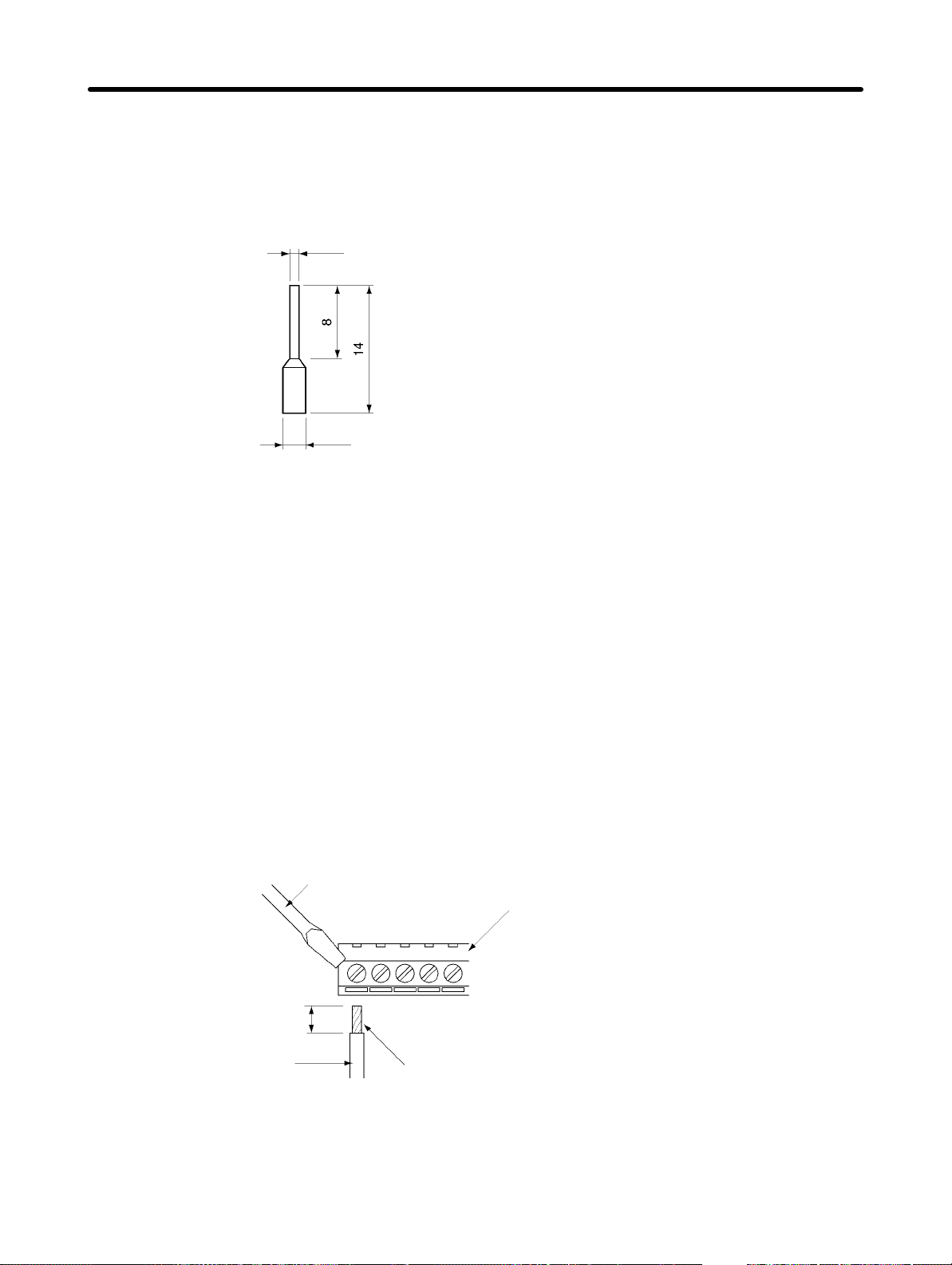
Design Chapter 2
D Solderless Terminal Size
The use of solderless terminals for the control circuit terminals is recommended for the reliability and
ease of connection.
Note Make sure that the wire size is 0.5 mm
1.0 dia.
2.6 dia.
2
when using the following solderless terminal.
Model: Phoenix Contact’s A1 0.5-8 WH
(Size: mm)
D Wiring Method
1. Loosen the terminal screws with a thin-slotted screwdriver.
2. Insert the wires from underneath the terminal block.
3. Tighten each terminal screw firmly to a torque specified in the previous tables.
Note 1. Always separate the control signal line from the main circuit cables and other power cables.
Note 2. Do not solder the wires to the control circuit terminals. The wires may not contact well with the
control circuit terminals if the wires are soldered.
Note 3. The end of each wire connected to the control circuit terminals must be stripped for approxi-
mately 5.5 mm.
Note 4. Connect the shield wire to the ground terminal of the 3G3JG. Do not connect the shield wire to
the device side being controlled.
Note 5. Be sure to insulate the shield wire with tape so that the shield wire will not come into contact
with other signal wires or equipment.
Thin-slotted screwdriver
Terminal block
Strip the end for approximately
5.5 mm if no solderless
terminal is used.
Wire
Solderless terminal or
wire without soldering.
Note Applying excessive torque may damage
the terminal block. If the tightening torque
is insufficient, however, wires may disconnect.
2-27
Page 53
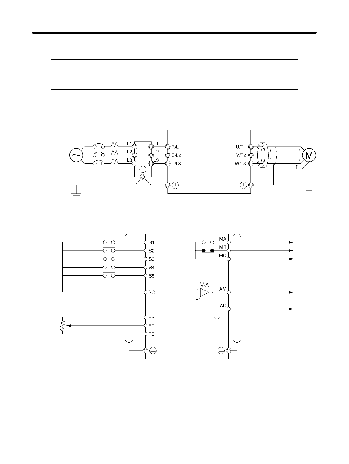
Design Chapter 2
2-2-6 Conforming to EC Directive
The following description provides the wiring method of the Inverter to meet DC Directive requirements. If the following requirements are not satisfied, the whole equipment
incorporating the Inverter will need further confirmation.
H Standard Connection
D Main Circuit Terminals
MCCBs
3-phase 200 V AC
Single-phase 200 V AC
3-phase 400 V AC
D Control Circuit Terminals
Forward/Stop
Multi-function input 1 (S2)
Multi-function input 2 (S3)
Multi-function input 3 (S4)
Multi-function input 4 (S5)
Sequence input common
Frequency reference power
supply at +12 V
FREQ
adjuster
Frequency reference input
Frequency reference common
Noise Filter
Clamp core
Multi-function contact output
NO
NC
Common
Analog-monitor output
Analog monitor output common
(2 kΩ, 1/4 W min.)
Note I/O signals can be connected to a single shielded cable.
2-28
Page 54
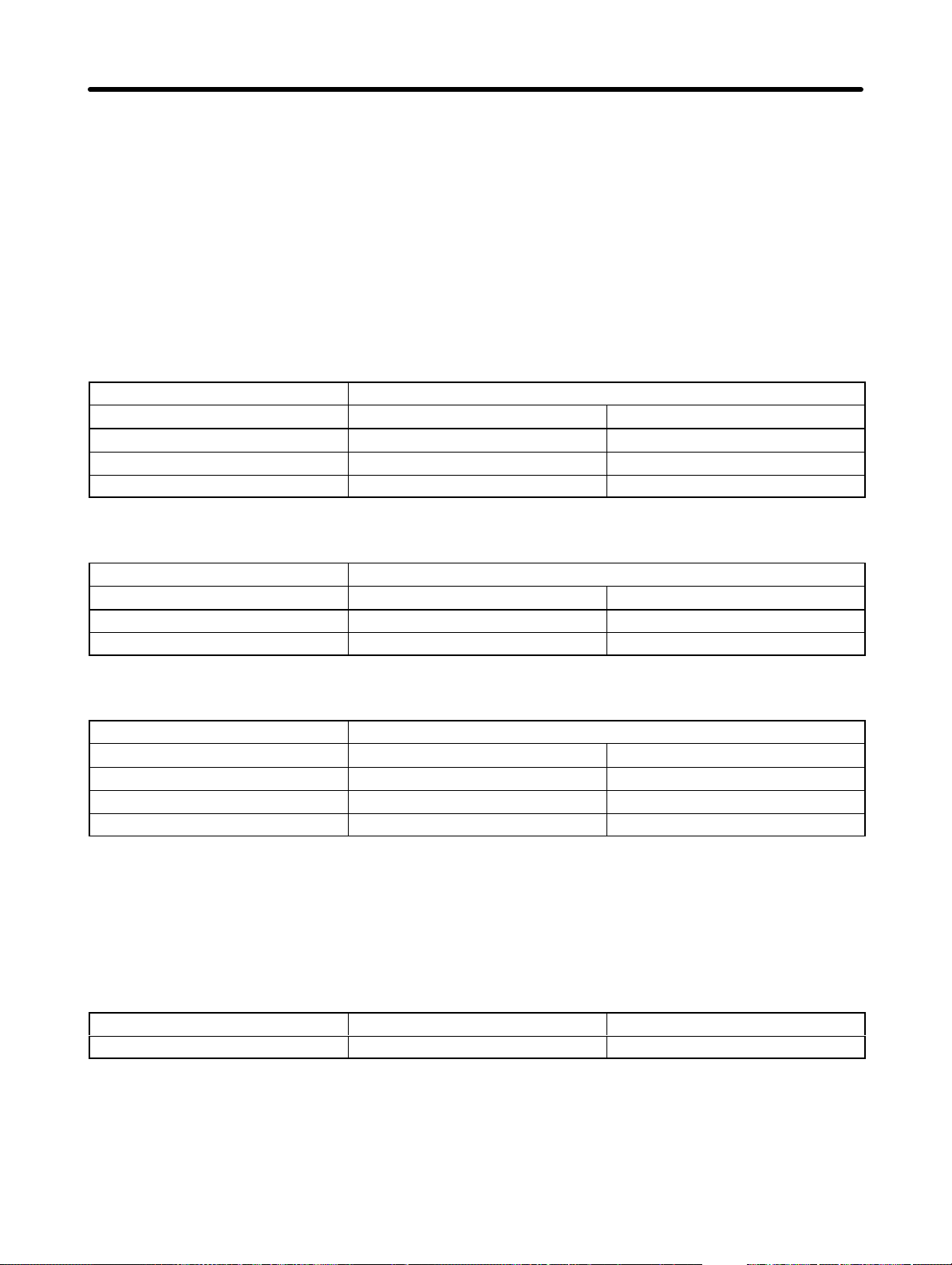
Design Chapter 2
D Wiring the Power Supply
Make sure that the Inverter and Noise Filter are grounded together.
• Always connect the power input terminals (R/L1, S/L2, and T/L3) and power supply via a dedicated
Noise Filter.
• Reduce the length of the ground wire as much as possible.
• Locate the Noise Filter as close as possible to the Inverter. Make sure that the cable length between
the Noise Filter and the Inverter does not exceed 40 cm.
• The following Noise Filters are available.
3-phase 200-V AC Noise Filter
Inverter 3-phase 200-V AC Noise Filter (Rasmi)
Model 3G3JV- Model 3G3JV- Rated current (A)
A2001/A2002/A2004/A2007 PRS2010J 10
A2015/A2022 PRS2020J 16
A2037 PRS2030J 26
Single-phase 200-V AC Noise Filter
Inverter Single-phase 200-V Noise Filter (Rasmi)
Model 3G3JV- Model 3G3JV- Rated current (A)
AB001/AB002/AB004 PRS1010J 10
AB007/AB015 PRS1020J 20
3-phase 400-V AC Noise Filter
Inverter 3-phase 200-V AC Noise Filter (Rasmi)
Model 3G3JV- Model 3G3JV- Rated current (A)
A4002/A4004 PRS3005J 5
A4007/A4015/A4022 PRS3010J 10
A4037 PRS3020J 15
D Connecting a Motor to the Inverter
• When connecting a motor to the Inverter, be sure to use a cable with a braided shield.
• Reduce the length of the cable as short as possible and ground the shield on the Inverter side as well
as the motor side. Make sure that the cable length between the Inverter and the motor does not exceed
20 m. Furthermore, connect a clamp core (Clamp Filter) close to the output terminals of the Inverter.
Product Model Manufacturer
Clamp Filter 2CAT3035-1330 TDK
D Wiring a Control Cable
• Be sure to connect a cable with a braided shield to the control circuit terminals.
• Ground the shield on the Inverter side only.
2-29
Page 55
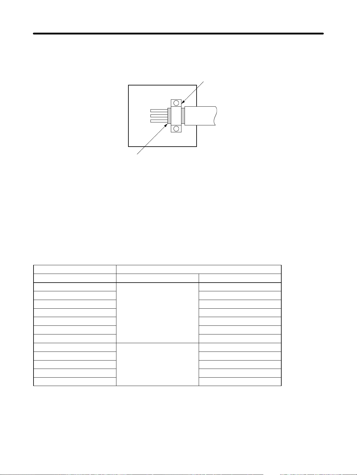
Design Chapter 2
D Grounding the Shield
In order to ground the shield securely, it is recommended that a cable clamp be directly connected to the
ground plate as shown below.
Ground plate
Shield
Cable clamp
Cable
H LVD Conformance
• Always connect the Inverter and power supply via a molded case circuit breaker
(MCCB) suitable to the Inverter for protecting the Inverter from damage that may result from short-circuiting.
• Use one MCCB per Inverter.
• Select a suitable MCCB from the following table.
• With 400-V Inverters, it is necessary to ground to the power supply’s neutral phase.
200-V Models
Inverter MCCB (Mitsubishi Electric)
Model 3G3JV- Type Rated current (A)
A2001
A2002 5
A2004 5
A2007 10
A2015 20
A2022 20
A2037 30
AB001
AB002 5
AB004 10
AB007 20
AB015 20
NF30
NF30
5
5
2-30
Page 56
Design Chapter 2
400-V Models
Inverter MCCB (Mitsubishi Electric)
Model 3G3JV- Type Rated current (A)
A4002
A4004 5
A4007 5
A4015 10
A4022 10
A4037 20
To satisfy LVD (Low-voltage Directive) requirements, the system must be protected by a molded case
circuit breaker (MCCB) when a short-circuit occurs. A single MCCB may be shared with more than one
Inverter or with other machines. In that case, however, take some appropriate measures so that the
MCCB will protect all the Inverters from the occurrence of any single short-circuit.
The frequency reference power supply (FS) of the Inverter is of basic insulation construction. When
connecting the Inverter to peripheral devices, be sure to increase the degree of insulation.
NF30
5
2-31
Page 57
3
Chapter 3
Preparing for
Operation and
Monitoring
3-1 Nomenclature
3-2 Parameter Copy and Verify Function
Page 58
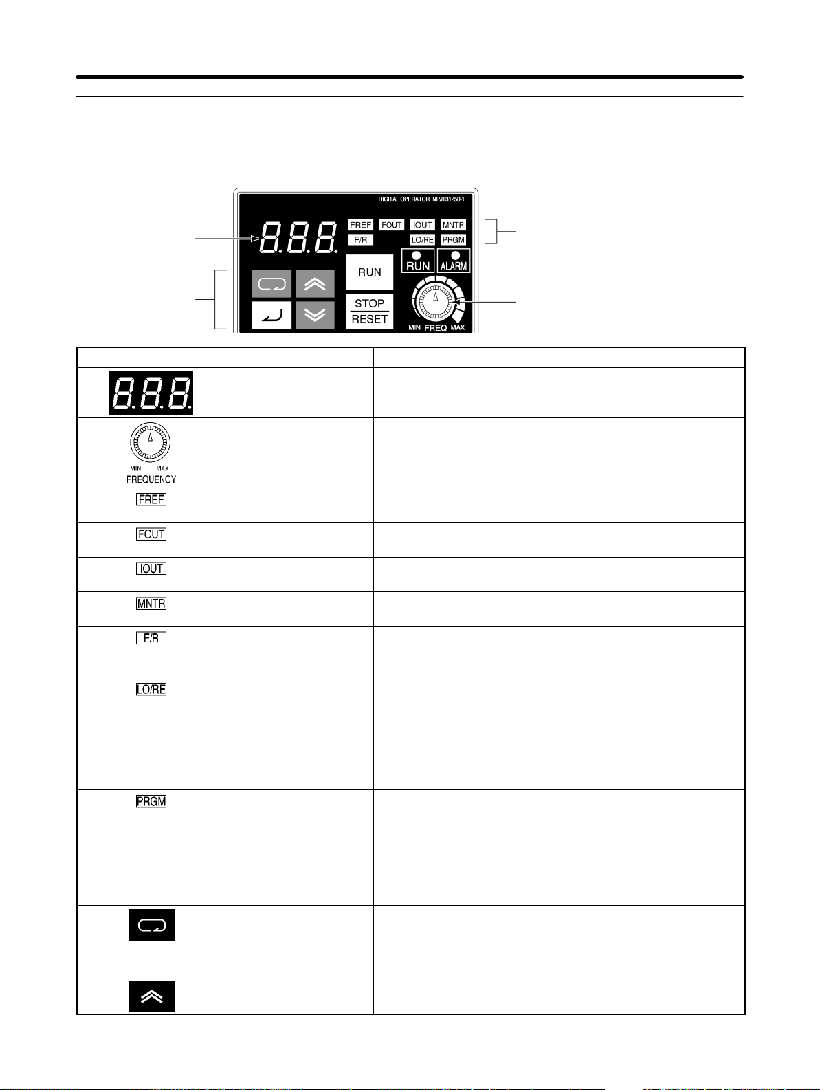
Preparing for Operation and Monitoring Chapter 3
3-1 Nomenclature
3-1-1 Part Names and Functions
Data display
Keys
Appearance Name Function
Data display Displays relevant data items, such as frequency reference,
output frequency, and parameter set values.
FREQ adjuster Sets the frequency reference within a range between 0 Hz
and the maximum frequency.
FREF indicator The frequency reference can be monitored or set while this
indicator is lit.
FOUT indicator The output frequency of the Inverter can be monitored
while this indicator is lit.
IOUT indicator The output current of the Inverter can be monitored while
this indicator is lit.
MNTR indicator The values set in U01 through U10 are monitored while
this indicator is lit.
F/R indicator The direction of rotation can be selected while this
indicator is lit, when operating the Inverter with the RUN
Key.
LO/RE indicator The operation of the Inverter through the Digital Operator
or according to the parameters set is selectable while this
indicator is lit.
Indicators
Setting/Monitor item indicators
FREQ adjuster
3-2
Note This status of this indicator can be only monitored
while the Inverter is in operation. Any RUN command
input is ignored while this indicator is lit.
PRGM indicator The parameters in n01 through n79 can be set or
monitored while this indicator is lit.
Note While the Inverter is in operation, the parameters can
be only monitored and only some parameters can be
changed. The RUN command input is ignored while
this indicator is lit.
Mode Key Switches the setting and monitor item indicators in
sequence.
Parameter setting being made is canceled if this key is
pressed before entering the setting.
Increment Key Increases multi-function monitor numbers, parameter
numbers, and parameter set values.
Page 59
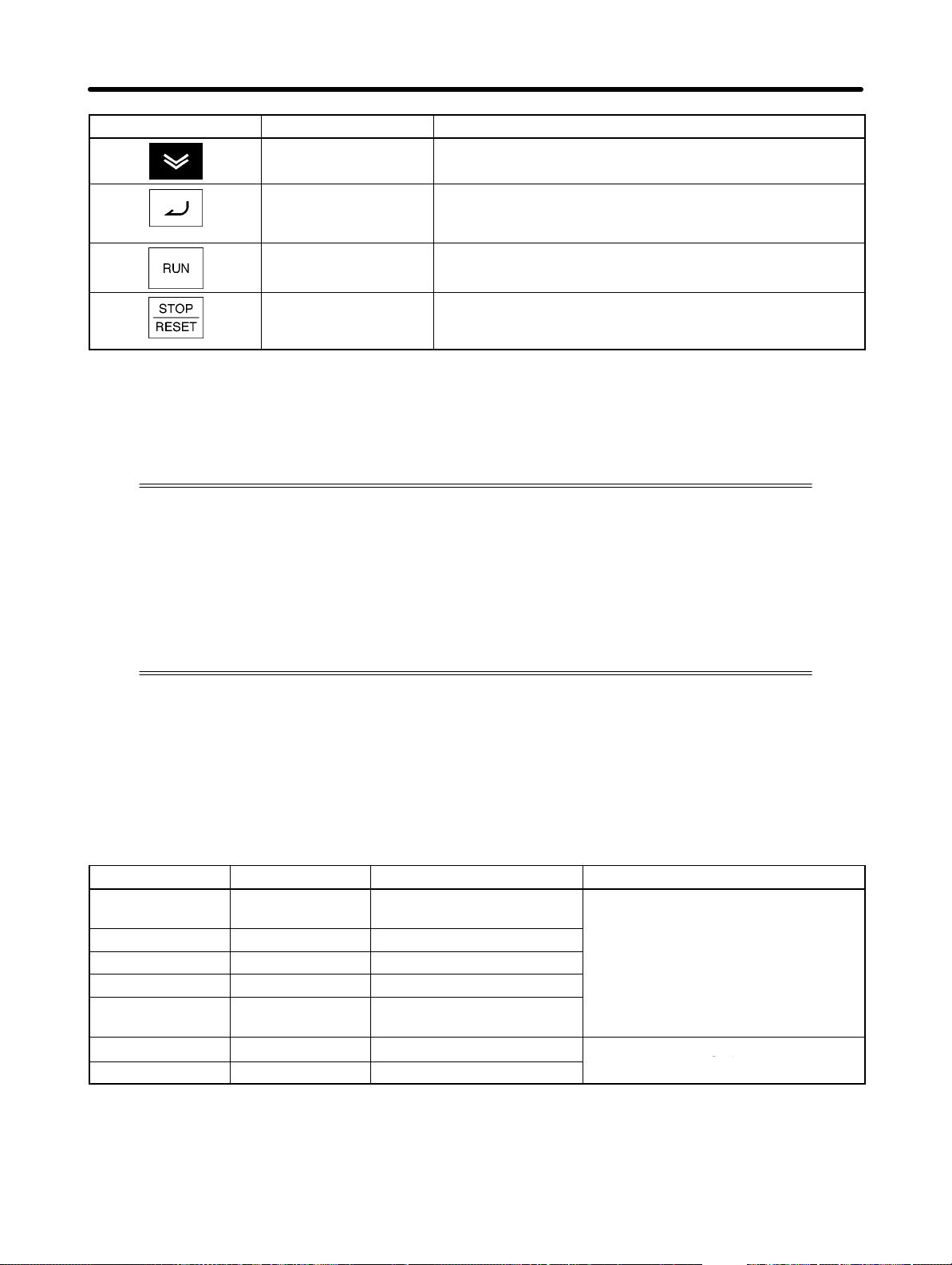
Drive Mode while operation is
stopped
gp
Preparing for Operation and Monitoring Chapter 3
Appearance FunctionName
Decrement Key Decreases multi-function monitor numbers, parameter
numbers, and parameter set values.
Enter Key Enters multi-function monitor numbers, parameter
numbers, and internal data values after they are set or
changed.
RUN Key Starts the Inverter running when the 3G3FV is in operation
with the Digital Operator.
STOP/RESET Key Stops the Inverter unless n06 is set to disable the STOP
Key. Functions as a Reset Key when an Inverter error
occurs. (See note.)
Note For safety’s reasons, the reset will not work while a RUN command (forward or reverse) is in ef-
fect. Wait until the RUN command is OFF before resetting the Inverter.
3-1-2 Drive Mode and Program Mode
The Inverter has two states: Drive Mode and Program Mode. Drive Mode is for receiving
operation commands, and Program Mode is for performing operations such as changing settings. With the default settings, Program Mode is set to not receive operation
commands to prevent the Servomotor from rotating if an operation command is mistakenly turned ON while parameters are being changed, such as for trial operation. Depending on the usage conditions, however, the user may want to have operation commands always received even while parameters are being changed. In that case, make
the following changes to the settings.
H Determining Modes with Indicators
You can find out from the indicators on the Digital Operator if Drive Mode or Program Mode is being
used. When the indicator is lit green, Drive Mode is being used.
When the indicator is lit red, Drive Mode is being used if the Servomotor is operating, and Program
Mode is used if the Servomotor is stopped. Therefore, operation will continue and the indicator will turn
red if the mode is changed during operation, but once the Servomotor is stopped, operation will not be
performed the next time the operation command is turned ON.
Indicators Indicator color Name Mode
FREF Green Frequency reference
monitor
FOUT Green Output frequency monitor
IOUT Green Output current monitor
MNTR Green Multi-function monitor
F/R Green Operator RUN command
forward/reverse selection
LO/RE Red Local/remote selection
PRGM Red Parameter No./data
D Setting Parameters
If the following setting is made, operation commands will always be received in Drive Mode even if the
indicator is lit red.
Drive Mode during operation
stopped
Drive Mode during operation
Program Mode (operation stopped)
3-3
Page 60

Preparing for Operation and Monitoring Chapter 3
Set n01 (Parameter Write-prohibit Selection/Parameter Initialization) to 5.
Note 1. The default setting for n01 is 1.
Note 2. As an exception, operation commands are not received when n01 itself is being changed.
Note 3. Some parameters can be changed during operation and other parameters cannot. This is not
affected by the setting of n01. If the setting for n01 has been changed to 5, operation commands will be received even while parameters are being changed, such as during testing.
Sufficiently check safety before operation.
3-4
Page 61
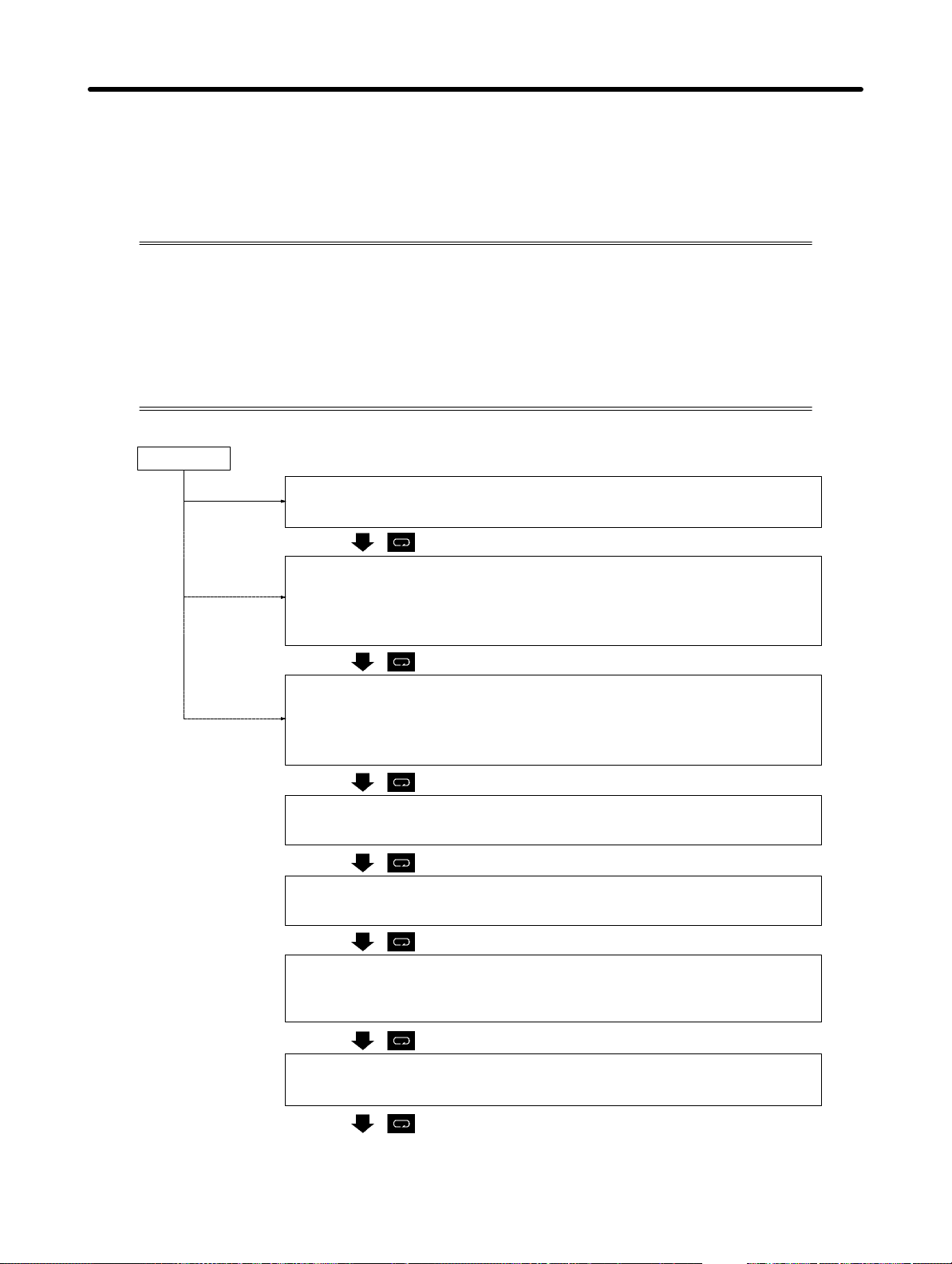
Preparing for Operation and Monitoring Chapter 3
3-1-3 Outline of Operation
H Selecting Indicators
Whenever the Mode Key is pressed, an indicator is lit in sequence beginning with the
FREF indicator. The data display indicates the item corresponding to the indicator selected.
The FOUT or IOUT indicator will be lit by turning the Inverter on again if the Inverter is
turned off while the FOUT or IOUT indicator is lit. The FREF indicator will be lit by turning
the Inverter on again if the Inverter is turned off while an indicator other than the FOUR or
IOUT indicator is lit.
Power On
FREF (Frequency Reference)
Monitors and sets the frequency reference.
FOUT (Output Frequency)
Monitors the output frequency.
Note This indicator will be lit by turning the Inverter on again if the Inverter
is turned off while this indicator is lit.
IOUT (Output Current)
Monitors the output current.
Note This indicator will be lit by turning the Inverter on again if the Inverter
is turned off while this indicator is lit.
MNTR (Multi-function Monitor)
Monitors the values set in U01 through U10.
F/R (Forward/Reverse Rotation)
Selects the direction of rotation.
LO/RE (Local/Remote)
Selects the operation of the Inverter through the Digital Operator or
according to the parameters.
PRGM (Parameter Setting)
Monitors or sets the values in n01 through n79.
The FREF indicator is lit again.
3-5
Page 62
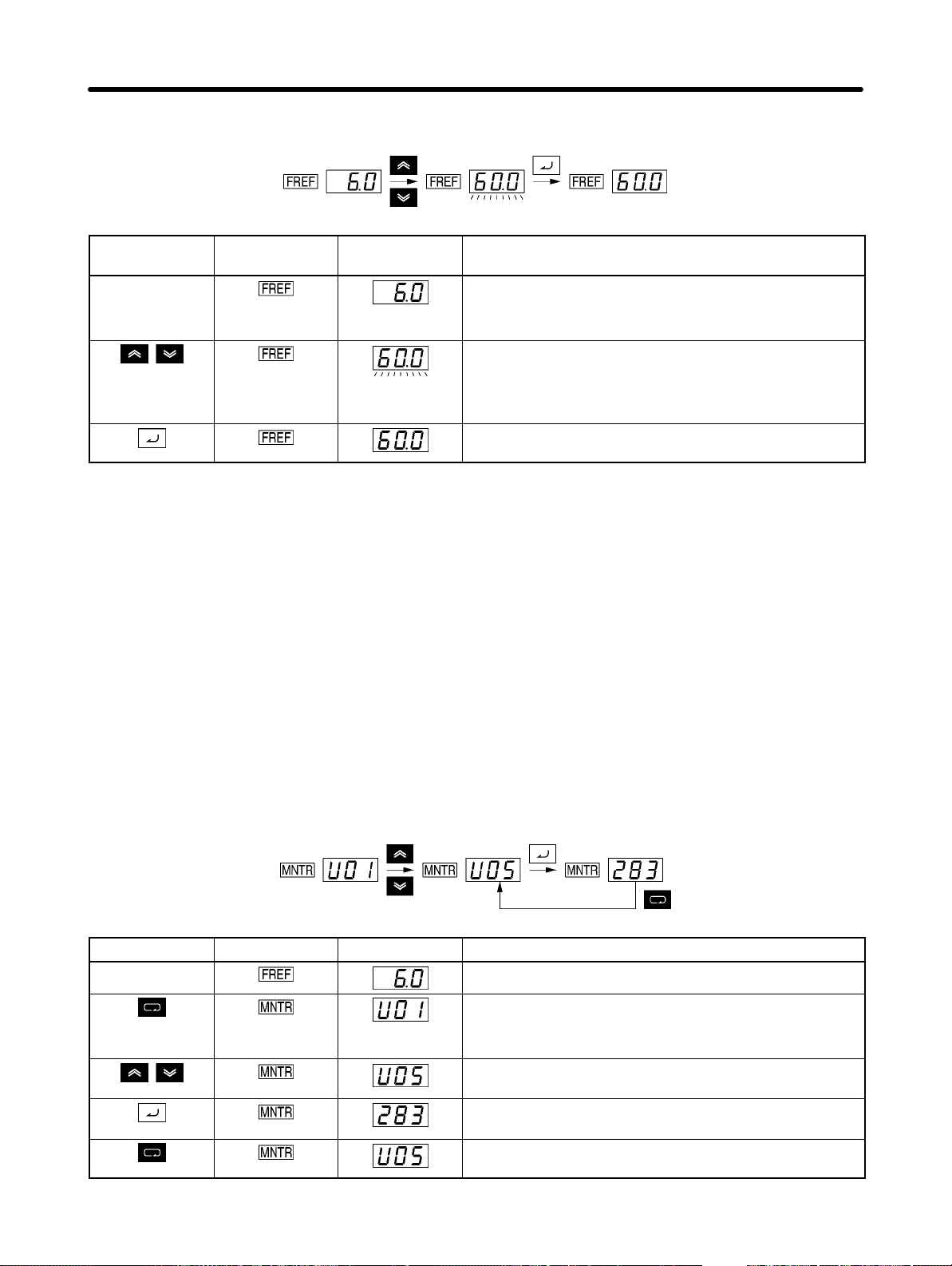
Preparing for Operation and Monitoring Chapter 3
H Example of Frequency Reference Settings
Key sequence Indicator Display
example
Power On
Note If the FREF indicator has not been lit, press the
Mode Key repeatedly until the FREF indicator is lit.
Use the Increment or Decrement Key to set the
frequency reference.
The data display will flash while the frequency
reference is set. (see note 1)
Press the Enter Key so that the set value will be
entered and the data display will be lit. (see note 1)
Explanation
Note 1. The Enter Key need not be pressed when performing the setting for n08. The frequency refer-
ence will change when the set value is changed with the Increment or Decrement Key while
the data display is continuously lit.
Note 2. The frequency reference can be set in either of the following cases.
S Parameter n03 for frequency reference selection is set to 1 (i.e., frequency reference 1 is en-
abled) and the Inverter is in remote mode.
S Parameter n07 for frequency selection in local mode is set to 1 (i.e., the Digital Operator is en-
abled) and the Inverter is in local mode.
S Frequency references 2 through 8 are input for multi-step speed operation.
Note 3. The frequency reference can be changed, even during operation.
H Example of Multi-function Display
Key sequence Indicator Display Explanation
Power On
Press the Mode Key repeatedly until the MNTR
indicator is lit.
U01 will be displayed.
Use the Increment or Decrement Key to select the
monitor item to be displayed.
Press the Enter Key so that the data of the selected
monitor item will be displayed.
The monitor number display will appear again by
pressing the Mode Key.
3-6
Page 63
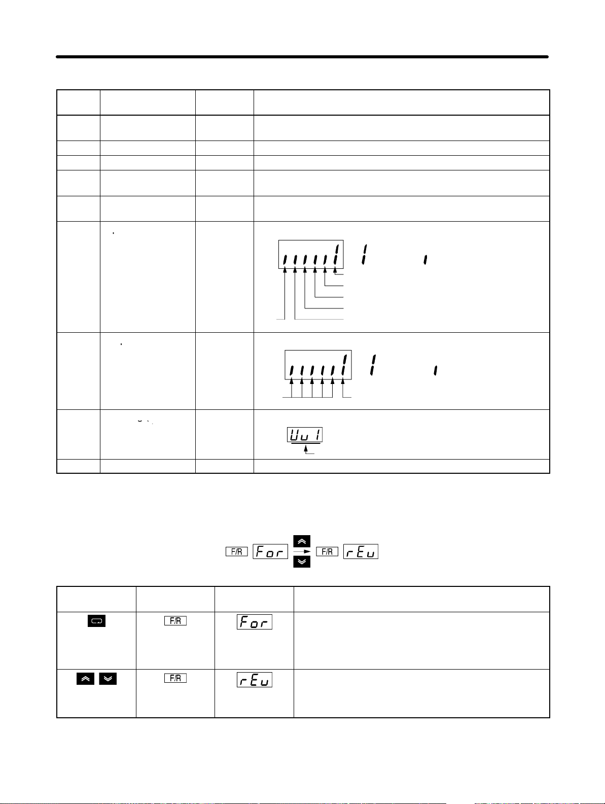
p
p
g(
Preparing for Operation and Monitoring Chapter 3
D Status Monitor
Item Display Display
unit
U01 Frequency
reference
U02 Output frequency Hz Monitors the output frequency. (Same as FOUT)
U03 Output current A Monitors the output current. (Same as IOUT)
U04 Output voltage V Monitors the internal output voltage reference value of the
U05 DC bus voltage V Monitors the DC voltage of the internal main circuit of the
U06 Input terminal ---
status
U07 Output terminal ---
status
Hz Monitors the frequency reference. (Same as FREF)
Inverter.
Inverter.
Shows the ON/OFF status of inputs.
Terminal S1: Forward/Stop
Terminal S2: Multi-function input 1 (S2)
Terminal S3: Multi-function input 2 (S3)
Not
used
Shows the ON/OFF status of outputs.
Terminal S4: Multi-function input 3 (S4)
Terminal S5: Multi-function input 4 (S5)
Function
: Input ON : No input
: Closed : Open
Not
used
U09 Error log (most
recent one)
U10 Software No. --- OMRON use only.
---
Displays the latest error.
Error
Terminal MA: Multi-function contact
output
H Example of Forward/Reverse Selection Settings
Key sequence Indicator Display
example
Press the Mode Key repeatedly until the F/R indicator
is lit.
The present setting will be displayed.
For: Forward; rEv: Reverse
Use the Increment or Decrement Key to change the
direction of motor rotation. The direction of motor
rotation selected will be enabled when the display
changes after the key is pressed.
Explanation
Note The direction of motor rotation can be changed, even during operation.
3-7
Page 64
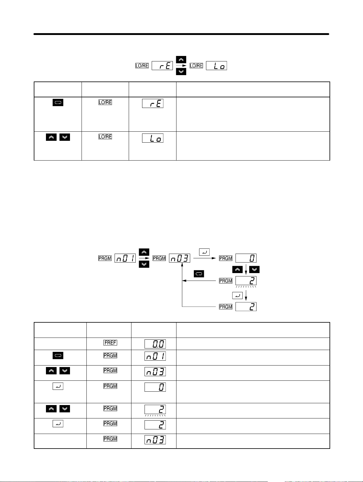
Preparing for Operation and Monitoring Chapter 3
H Example of Local/Remote Selection Settings
Key sequence Indicator Display
example
Press the Mode Key repeatedly until the LO/RE
indicator is lit.
The present setting will be displayed.
rE: Remote; Lo: Local
Use the Increment or Decrement Key to set the
Inverter to local or remote mode. The selection will be
enabled when the display changes after the key is
pressed.
Explanation
Note 1. Local or remote selection is possible only when the Inverter is not in operation. The present
setting can be monitored when the Inverter is in operation.
Note 2. Local or remote settings in multi-function input terminals can be changed through the multi-
function input terminals only.
Note 3. Any RUN command input will be ignored while the LO/RE indicator is lit. To enable a RUN
command, first turn the RUN command OFF and then press the Mode Key to display an item
that has a green indicator (FREF to MNTR). Then input the RUN command again.
H Example of Parameter Settings
Key sequence Indicator Display
example
In approximately
1 s.
Cancels set data.
In approximately 1 s.
Explanation
Power On
Press the Mode Key repeatedly until the PRGM
indicator is lit.
Use the Increment or Decrement Key to set the
parameter number.
Press the Enter Key.
The data of the selected parameter number will be
displayed.
Use the Increment or Decrement Key to set the data.
At that time the display will flash.
Press the Enter Key so that the set value will be
entered and the data display will be lit. (see note 1)
The parameter number will be displayed.
3-8
Page 65

Preparing for Operation and Monitoring Chapter 3
Note 1. To cancel the set value, press the Mode Key instead. The parameter number will be dis-
played.
Note 2. There are parameters that cannot be changed while the Inverter is in operation. Refer to the
list of parameters. When attempting to change such parameters, the data display will not
change by pressing the Increment or Decrement Key.
Note 3. Any RUN command input will be ignored while the Parameter Setting (PRGM) indicator is lit.
To enable a RUN command, first turn the RUN command OFF and then press the Mode Key
to display an item that has a green indicator (FREF to MNTR). Then input the RUN command
again.
3-9
Page 66

Preparing for Operation and Monitoring Chapter 3
3-2 Parameter Copy and Verify Function
The 3G3IV-PJVOP140 and 3G3IV-PJVOP146 Digital Operators include EEPROM
memory. All the parameters for the Inverter, the Inverter capacity, and the software version are saved in this memory. If the memory is used, the parameter settings for the
Inverter can be copied to other Inverters.
Note: Copying can be performed between Inverters with the same power supply speci-
fications. Some parameters, however, may not be copied.
3-2-1 Parameters for the Parameter Copy and Verify Function
The following table shows the parameters used when reading, copying (i.e., writing), and verifying parameters.
Parameter
No.
n76 014C Paramet
Register
No.
Name Description Setting
er Copy
and
Verify
Function
Selects the function for
copying parameters.
Rdy: Ready to accept the
next command.
Red: Read the Inverter
parameters.
Cpy: Copy the parameters
to the Inverter.
VFy: Verify the Inverter
parameters.
Va: Verify the Inverter
capacity display.
Sno: Verify the software
number.
range
rdy to
Sno
Setting
unit
--- rdy
Default
setting
operation
Writing
during
3-10
Page 67
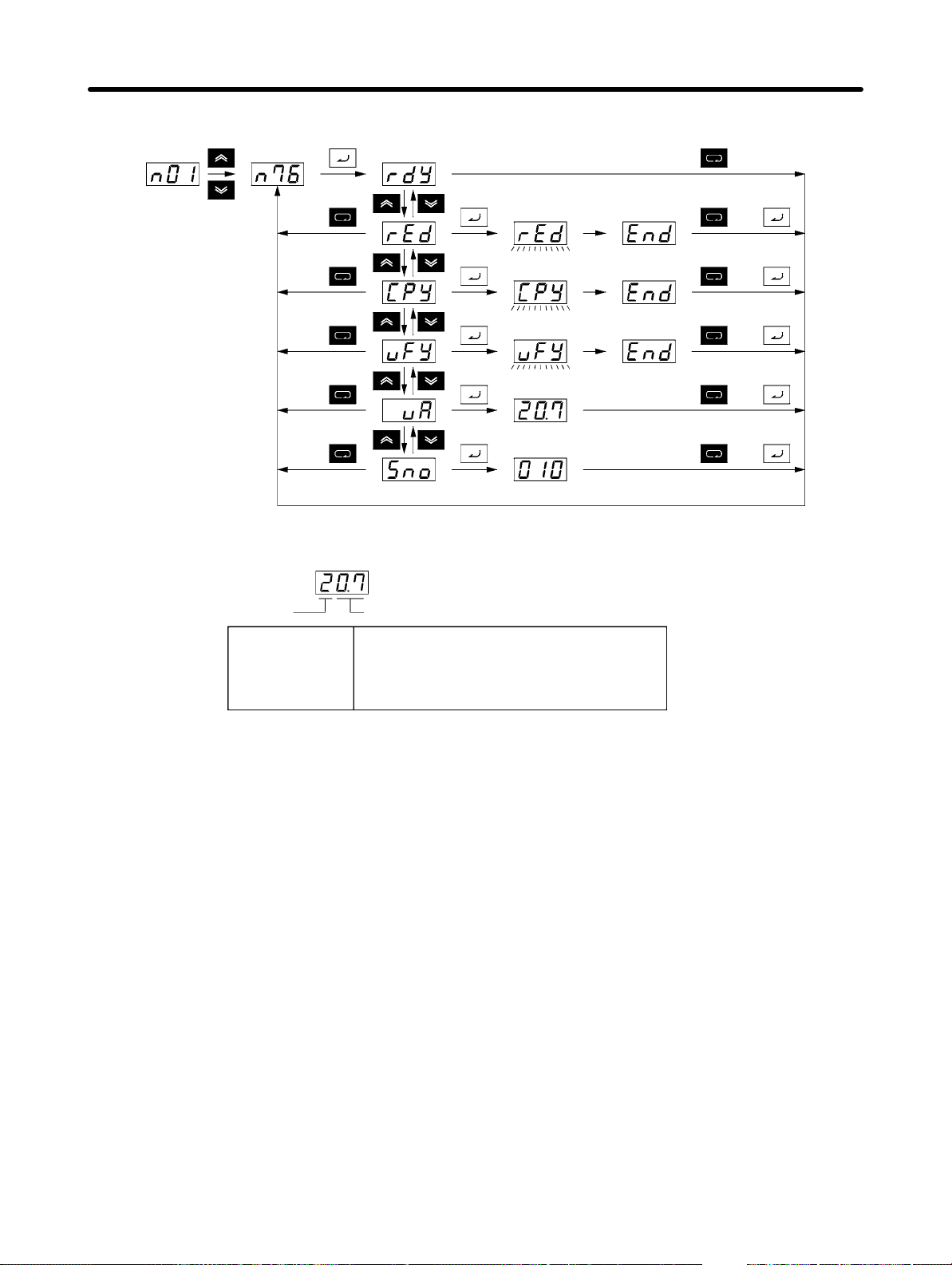
Preparing for Operation and Monitoring Chapter 3
H Display Transitions
Reading
Writing
Verifying
Inverter capacity
Software No.
Reading
completed
Writing
completed
Verifying
completed
Note The following table shows the display for the Inverter capacity (vA).
Voltage class
2: Three-phase 200 V
b: Single-phase 200 V
4: Three-phase 400 V
Maximum applicable Servomotor capacity
0.1: 0.1 kW (0.1 kW)
0.2: 0.2 kW (0.25 kW/0.37 kW)
0.4: 0.4 kW (0.55 kW)
0.7: 0.75 kW (1.1 kW)
1.5: 1.5 kW (1.5 kW)
2.2: 2.2 kW (2.2 kW)
3.7: 3.7 kW (3.7 kW)
or
or
or
or
or
Note The figures in parentheses indicate typical motor capacities in Japan.
3-2-2 Procedure for Copying Parameters
• Use the following procedure to copy parameters to another Inverter.
1. Set the Parameter Write-prohibit Selection/Parameter Initialization (n01) to 1.
2. Set the Parameter Read Prohibit Selection (n77) to 1 to enable reading.
3. Read the Inverter parameter settings to the Digital Operator memory (rEd).
4. Turn OFF the Inverter power supply, and remove the Digital Operator.
5. Install the Digital Operator on the Inverter you want to copy to, and then turn ON the power supply.
6. Copy the contents of the memory in the Digital Operator to the Inverter (CPy).
7. Verify and check that writing was performed correctly (vFy).
• Parameters can be copied only between Inverters that have the same power supply specifications
and control mode (i.e., V/f control or vector control). For example, copying cannot be performed from a
200-V-class Inverter to a 400-V-class Inverter or from a V/f-control-mode Inverter to a vector-controlmode Inverter.
Note The saved hold output frequency and the following parameters will not be copied.
3-11
Page 68
Preparing for Operation and Monitoring Chapter 3
n76: Parameter Copy and Verify Function
n77: Parameter Read Prohibit Selection
n78: Error Log
n79: Software Number
H Setting the Parameter Write-prohibit Selection/Parameter Initialization
(n01)
Writing to the Parameter Copy and Verify Function (n76) cannot be performed with the default setting.
To write to n76, set the Parameter Write-prohibit Selection/Parameter Initialization (n01) to 1. (The procedure described here is not required if n01 is already set to 1.)
Parameter
No.
n01 0101 Parameter
Register
No.
Name Description Setting
Write-prohibit Selection/Parameter Initialization
This parameter is used to prohibit
writing to parameters to be written, to
enable setting parameters, or to
change the monitor range of parameters.
0: Enables setting or monitoring
parameter n01. Parameters n02
to n79 can be monitored only.
1: Enables setting parameters n01
to n49.
5: Enables continuous operation.
(Parameters n01 to n79 can be
set or monitored.)
6: Clears the error log.
8: Initializes parameters to the de-
fault values for 2-wire sequence.
9: Initializes parameters to the de-
fault values for 3-wire sequence.
Note With settings 0 or 1, operation
commands are ignored in Program Mode. (Refer to 3-1-2
Drive Mode and Program
Mode.) Normally, use a setting
of 0 or 1.
Setting
range
0 to 9 1 1
unit
Default
setting
operation
Writing
during
3-12
Page 69
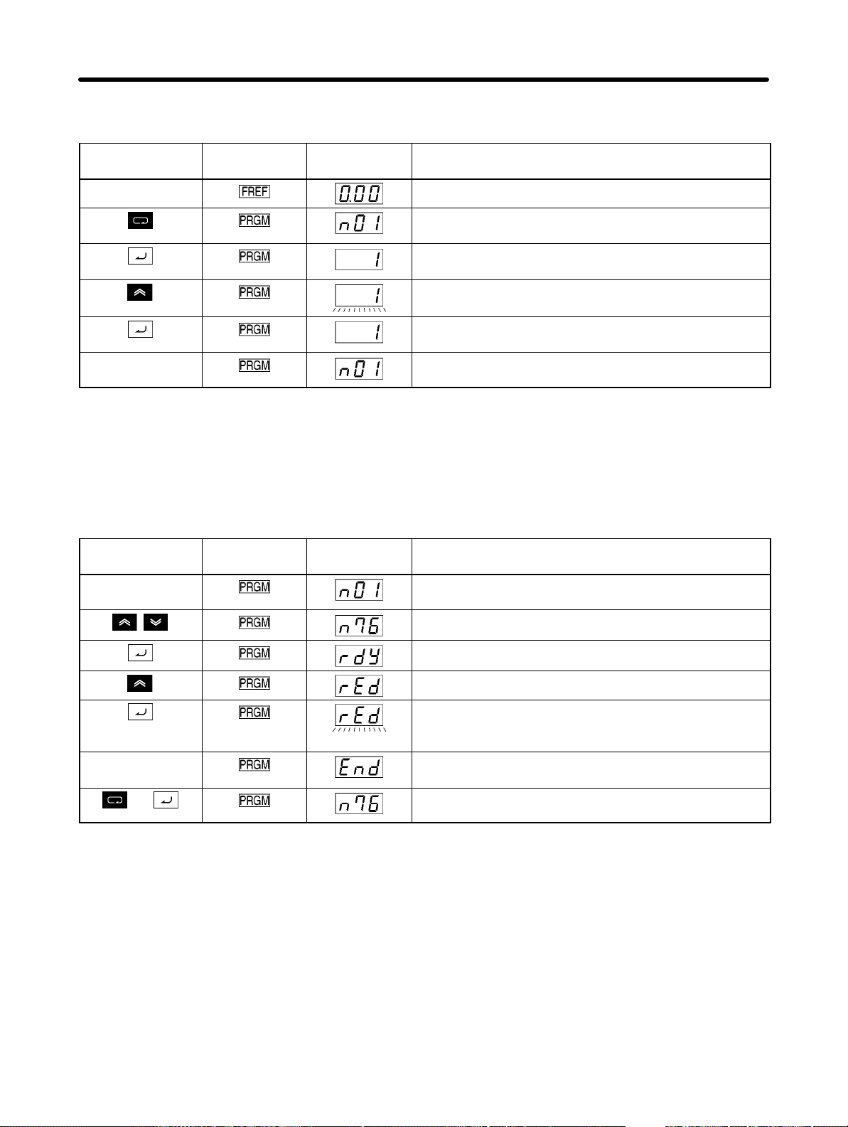
Preparing for Operation and Monitoring Chapter 3
D Procedure for Setting the Parameter Write-prohibit Selection/Parameter
Initialization (n01)
Key sequence Indicators Display
example
In approximately
1 s.
Power ON
Press the Mode Key until the PRGM indicator lights.
Check that n01 is shown on the data display.
Press the Enter Key. The setting for the specified
parameter will be displayed.
Press the Increment Key to display 1. (The display will
flash.)
Press the Enter Key to enter the setting. The display
will stop flashing.
The parameter number will be displayed.
Explanation
H Reading Parameter Settings (rEd)
The parameter settings saved in the Inverter can be read to the memory of the Digital Operator by setting the Parameter Copy and Verify Function (n76) to “rEd.”
D Procedure for Reading Parameter Settings
Key sequence Indicators Display
example
Check that PRGM is lit. (Press the Mode Key if any
other indicator is lit.)
Use the Increment or Decrement Key to display n76.
Explanation
(After
completion)
or
Press the Enter Key. “rdy” will flash.
Press the Increment Key to display “rEd”.
Press the Enter Key. The Inverter parameters will be
read to the memory in the Digital Operator. During this
time, the display will flash.
When reading has been completed, “End” will be
displayed.
Press the Mode Key or the Enter Key to return to the
parameter number display.
3-13
Page 70

Preparing for Operation and Monitoring Chapter 3
H Copying the Memory Contents of the Digital Operator to the Inverter
(CPy)
• The parameter settings saved in the memory of the Digital Operator can be written to the Inverter by
setting the Parameter Copy and Verify Function (n76) to “Cpy.”
• When reading from the Digital Operator has been completed, turn OFF the Inverter power supply and
remove the Digital Operator.
• Install the Digital Operator on the Inverter to which the parameters are to be written and turn ON the
power supply.
• In the Parameter Write-prohibit Selection/Parameter Initialization (n01) is not set to 1 for that Inverter,
use the same procedure as described above to set it to 1.
Note Parameters can be copied only between Inverters with the same power supply specifications.
D Procedure for Writing the Memory Contents of the Digital Operator
Key sequence Indicators Display
example
(After
completion)
or
Power ON
Press the Mode Key until the PRGM indicator lights.
Use the Increment or Decrement Key to display n76.
Press the Enter Key. “rdy” will be displayed.
Press the Increment Key to display “Cpy.”
Press the Enter Key. The parameters in the memory of
the Digital Operation will be written to the Inverter.
During this time, the display will flash.
When writing has been completed, “End” will be
displayed.
Press the Mode Key or the Enter Key to return to the
parameter number display.
Explanation
Note 1. A setting range check and consistency check will be performed for the parameters after the
memory contents of the Digital Operator have been written to the Inverter. If there is one or
more parameters with an error, all parameters will be returned to their previous settings and
none of them will be changed.
If there is a setting range error, the number of the parameter that caused the error will flash.
If there is a consistency error, oPj (j as a number) will flash.
Note 2. The saved hold output frequency and the following parameters cannot be copied.
n76: Parameter Copy and Verify Function
n77: Parameter Read Prohibit Selection
n78: Error Log
n79: Software Number
3-14
Page 71
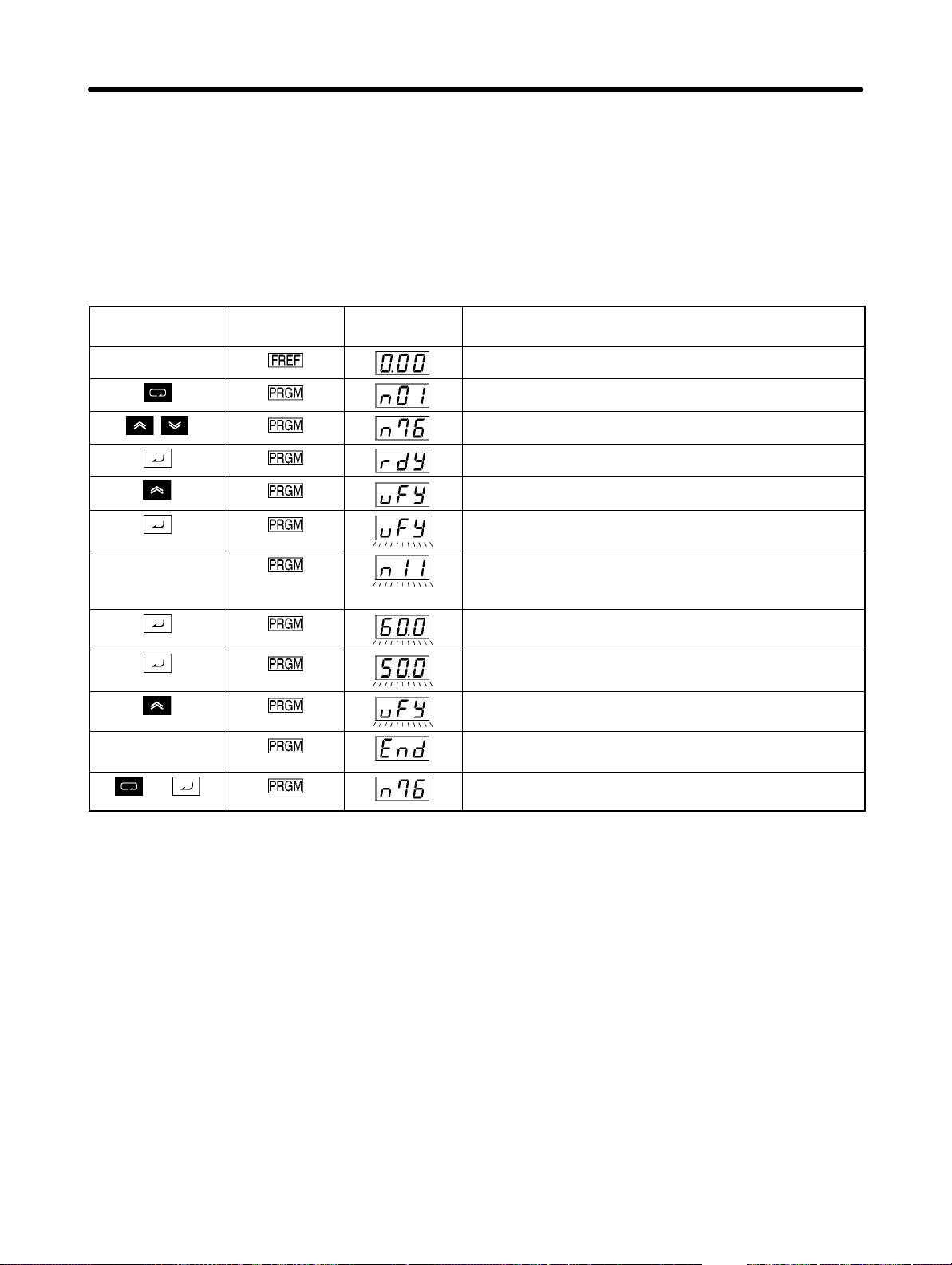
Preparing for Operation and Monitoring Chapter 3
H Verifying Parameters (vFy)
The parameter settings saved in the memory of the Digital Operator can be verified with the parameter
settings in the Inverter by setting the Parameter Copy and Verify Function (n76) to “vFy.”
Note Just as with copying, parameters can be verified only for Inverters that have the same power sup-
ply specifications.
D Procedure for Verifying Parameters
Key sequence Indicators Display
example
(After
completion)
or
Explanation
Power ON
Press the Mode Key until the PRGM indicator lights.
Use the Increment or Decrement Key to display n76.
Press the Enter Key. “rdy” will be displayed.
Press the Increment Key to display “vFy.”
Press the Enter Key. The parameters will be verified.
(During this time, the display will flash.)
If the settings of a parameter do not match, the
parameter number of the inconsistent parameter will
be flashed on the display.
The setting in the Inverter will be flashed first when the
Enter Key is pressed.
When the Enter Key is pressed again, the setting in the
Digital Operator will be flashed.
Verification will be continued when the Increment Key
is pressed.
When the verification has been completed, “End” will
be displayed.
Press the Mode Key or the Enter Key to return to the
parameter number display.
Note 1. Verification will be cancelled and the display will change to “End” if the STOP/RESET Key is
pressed while the number of an inconsistent parameter is being displayed or the setting is
being displayed. The display will then return to the number of the inconsistent parameter
when the Mode Key or the Enter Key is pressed.
Note 2. The display will flash “vAE” if you attempt to verify parameters between Inverters that have
different capacities. To continue verifying anyway, press the Enter Key. To cancel verifying,
press the STOP/RESET Key.
3-15
Page 72
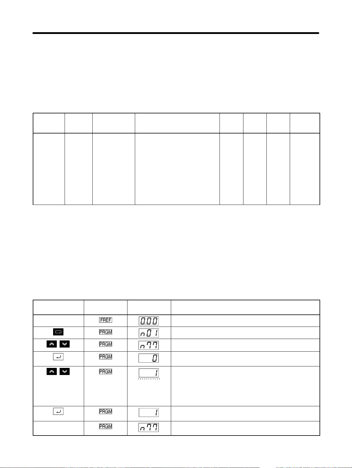
Preparing for Operation and Monitoring Chapter 3
3-2-3 Parameter Read Prohibit (Prohibiting Writing to Digital
Operator)
To protect the parameter settings saved in the memory of the Digital Operator, set the Parameter Read
Prohibit Selection (n77) to 0 (read prohibited).
If an attempt is made to read parameter settings from the Inverter, “PrE” (protect error) will be displayed,
and reading will not be possible. (Press the Mode Key to clear “PrE” from the display.)
Parameter
No.
n77 014D Parameter
Register
No.
Name Description Setting
Used to prohibit writing
Read Prohibit
Selection
parameters. Use this parameter
to protect the contents of the
EEPROM memory in the Digital
Operator.
0: Reading prohibited for
Inverter parameters (Data
cannot be written to EEPROM.)
1: Reading possible for Inverter
parameters (Data can be
written to EEPROM.)
Setting
range
0, 1 1 0
unit
Default
setting
operation
Writing
during
Note 1. It is not possible to write to the n77 parameter with the default setting. To enable writing to n77,
set the Parameter Write-prohibit Selection/Parameter Initialization (n01) to 1.
Note 2. This parameter is set in the Digital Operator. The setting for n77 will be 0 (read prohibited)
regardless of the Inverter setting if a Digital Operator that is set to prohibited reading is
installed on another Inverter.
D Procedure for Setting Parameter Read Prohibit Selection
Key sequence Indicators Display
example
Power ON
Press the Mode Key until the PRGM indicator lights.
Use the Increment or Decrement Key to display n77.
Press the Enter Key. The present settings will be
displayed.
Use the Increment or Decrement Key to set the data.
0: Reading prohibited for Inverter parameters (Data
cannot be written to EEPROM.)
1: Reading possible for Inverter parameters (Data
can be written to EEPROM.)
Press the Enter Key to enter the settings. The display
will flash.
In approximately
1 s.
The parameter number will be displayed.
3-16
Explanation
Page 73
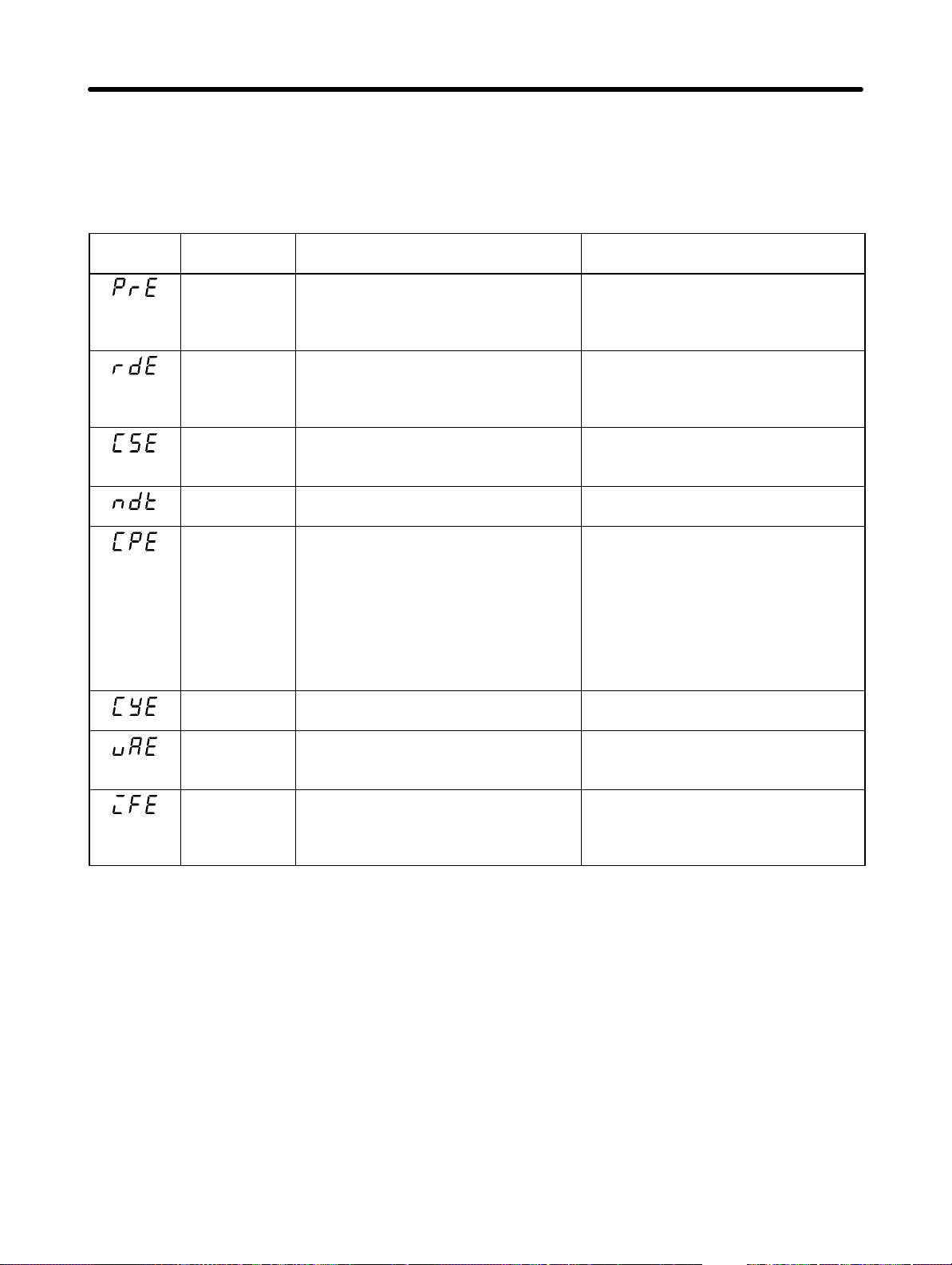
Preparing for Operation and Monitoring Chapter 3
3-2-4 Error Displays for the Parameter Copy and Verify
Function
This section describes the errors that may occur when reading, copying, or verifying parameters, and
the remedies for those errors. The display will flash when any of these errors occurs.
Display Probable
cause
Protect error A read attempt was made with the
Read error The parameters were not read
Checksum
error
No-data Error There are no parameters saved in the
Copy target
error
Voltage error
while copying
Capacity error An attempt was made to verify
Communications error
Name Remedy
Parameter Read Prohibit Selection
(n77) set to 0 (reading prohibited).
correctly or a low voltage was
detected in the main circuit when the
data was being read.
A checksum error occurred for the
parameters saved in the Digital
Operator.
Digital Operator.
An attempt was made to copy or verify
between Inverters with different
voltage classes or control modes.
A low voltage in the main circuit was
detected while data was being copied.
parameters between Inverters with
different capacities.
A communications error occurred
between the Inverter and the Digital
Operator.
Check again whether data must be
read, and if required, change the
setting for n77 to 1 (reading possible),
and then read the data again.
Check that the main circuit voltage is
normal, and then read the data again.
Read the parameters to the Digital
Operator again.
Read the parameters to the Digital
Operator.
Check the voltage classes and control
modes. (If either is different from that
of the other Inverter, copying and
verifying are not possible.)
If an Inverter has a different control
mode, change the control mode of the
Inverter to be copied to or verified,
and then copy or verify the
parameters again.
Check that the main voltage is
normal, and then copy the data again.
To continue verification, press the
Enter Key. To cancel verification,
press the STOP/RESET Key.
Check the connection between the
Inverter and the Digital Operator.
Make sure the connection is correct,
and then repeat the operation.
3-17
Page 74
Test Run
4-1 Procedure for Test Run
4-2 Operation Example
4
Chapter 4
Page 75

Test Run
Chapter 4
WARNING
!
WARNING Do not remove the front cover, terminal covers, bottom cover, Operator, or optional
!
WARNING Do not operate the Operator or switches with wet hands. Doing so may result in
!
WARNING Do not touch the inside of the Inverter. Doing so may result in electrical shock.
!
WARNING Do not come close to the machine when using the error retry function because the
!
WARNING Do not come close to the machine immediately after resetting momentary power
!
Turn ON the input power supply only after mounting the front cover, terminal covers,
bottom cover, Operator, and optional items. Not doing so may result in electrical
shock.
items while the power is being supplied. Not doing so may result in electrical shock or
damage to the product.
electrical shock.
machine may abruptly start when stopped by an alarm. Doing so may result in injury.
interruption to avoid an unexpected restart (if operation is set to be continued in the
processing selection function after momentary power interruption is reset). Doing so
may result in injury.
WARNING Provide a separate emergency stop switch because the STOP Key on the Operator
!
is valid only when function settings are performed. Not doing so may result in injury.
WARNING Be sure confirm that the RUN signal is turned OFF before turning ON the power
!
supply, resetting the alarm, or switching the LOCAL/REMOTE selector. Doing so
while the RUN signal is turned ON may result in injury.
Caution Be sure to confirm permissible ranges of motors and machines before operation be-
!
cause the Inverter speed can be easily changed from low to high. Not doing so may
result in damage to the product.
Caution Provide a separate holding brake when necessary. Not doing so may result in injury.
!
Caution Do not perform a signal check during operation. Doing so may result in injury or dam-
!
age to the product.
Caution Do not carelessly change settings. Doing so may result in injury or damage to the
!
product.
4-2
Page 76

Test Run
Chapter 4
4-1 Procedure for Test Run
1. Installation and Mounting
Install the Inverter according to the installation conditions. Refer to page 2-2. Ensure that the installation conditions are met.
2. Wiring and Connection
Connect to the power supply and peripheral devices. Refer to page 2-7. Select peripheral devices
which meet the specifications and wire correctly.
3. Power Connection
Carry out the following pre-connection checks before turning on the power supply.
S Always ensure that a power supply to the correct voltage is used and that the power input terminals
(R/L1, S/L2, and T/L3) are wired correctly.
3G3JV-A2j: 3-phase 200 to 230 V AC
3G3JV-ABj: Single-phase 200 to 240 V AC (Wire R/L1 and S/L2)
3G3JV-A4j: 3-phase 380 to 460 V AC
S Make sure that the motor output terminals (U/T1, V/T2, and W/T3) are connected to the motor
correctly.
S Ensure that the control circuit terminals and the control device are wired correctly. Make sure that
all control terminals are turned off.
S Set the motor to no-load status (i.e., not connected to the mechanical system).
S Having conducted the above checks, connect the power supply.
4. Check the Display Status
Check to be sure that there are no faults in the Inverter.
S If the display at the time the power is connected is normal, it will read as follows:
RUN indicator: Flashes
ALARM indicator: Off
Setting/Monitor indicators: FREF, FOUT, or IOUT is lit.
Data display: Displays the corresponding data of the indicator that is lit.
S When a fault has occurred, the details of the fault will be displayed. In that case, refer to Chapter 8
Maintenance Operations and take necessary remedies.
5. Initializing Parameters
Initialize the parameters.
S Set n01 to 8 for initialization in 2-wire sequence.
6. Setting Parameters
Set the parameters required for a test run.
S Set the rated motor current in order to prevent the motor from burning due to overloading.
7. No-load Operation
Start the no-load motor using the Digital Operator.
S Set the frequency reference using the Digital Operator and start the motor using key sequences.
4-3
Page 77

Test Run
8. Actual Load Operation
Connect the mechanical system and operate using the Digital Operator.
S When there are no difficulties using the no-load operation, connect the mechanical system to the
motor and operate using the Digital Operator.
9. Operation
Basic Operation:
Operation based on the basic settings required to start and stop the Inverter. Refer to page 5-1.
Advanced Operation:
Operation that uses PID control or other functions. Refer to page 6-1.
S For operation within standard parameters, refer to Chapter 5 Basic Operation.
S Refer to Chapter 5 Basic Operation and Chapter 6 Advanced Operation for the various advanced
functions, such as stall prevention, carrier frequency setting, overtorque detection, torque compensation, and slip compensation.
Chapter 4
4-4
Page 78

Test Run
Chapter 4
4-2 Operation Example
1 Power Connection
H Checkpoints before Connecting the Power Supply
• Check that the power supply is of the correct voltage and that the motor output terminals (R/L1, S/L2,
and T/L3) are connected to the motor correctly.
3G3JV-A2j: Three-phase 200 to 230 V AC
3G3JV-ABj: Single-phase 200 to 240 V AC (Wire R/L1 and S/L2)
3G3JV-A4j: 3-phase 380 to 460 V AC
• Make sure that the motor output terminals (U/T1, V/T2, and W/T3) are connected to the motor correctly.
• Ensure that the control circuit terminals and the control device are wired correctly. Make sure that all
control terminals are turned off.
• Set the motor to no-load status (i.e., not connected to the mechanical system).
H Connecting the Power Supply
• After conducting the above checks, connect the power supply.
2 Check the Display Status
• If the display is normal when the power is connected, it will read as follows:
Normal
RUN indicator: Flashes
ALARM indicator: Off
Setting/Monitor indicators: FREF, FOUT, or IOUT is lit.
Data display: Displays the corresponding data for the indicator that is lit.
• When a fault has occurred, the details of the fault will be displayed. In that case, refer to Chapter 8
Maintenance Operations and take necessary action.
Fault
RUN indicator: Flashes
ALARM indicator: Lit (fault detection) or flashes (alarm detection)
Setting/Monitor indicators: FREF, FOUT, or IOUT is lit.
Data display: The fault code, such as UV1, is displayed. The display will differ depending on the type
of fault.
4-5
Page 79
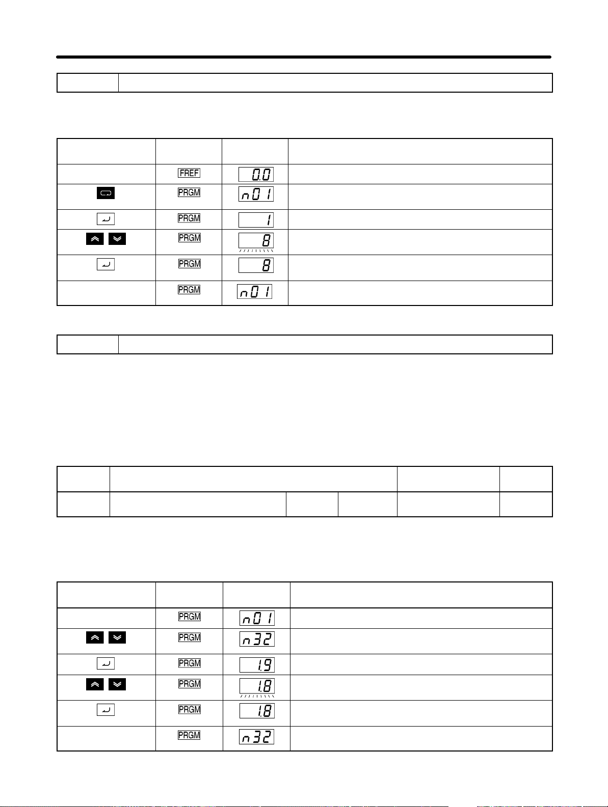
Test Run
3 Initializing Parameters
• Initialize the parameters using the following procedure.
• To initialize the parameters, set n01 to 8.
Chapter 4
Key sequence Indicator Display
example
In approximately
1 s.
Power On
Press the Mode Key repeatedly until the PRGM indicator
is lit.
Press the Enter Key. The data of n01 will be displayed.
Use the Increment or Decrement Key to set n01 to 8.
The display will flash.
Press the Enter Key so that the set value will be entered
and the data display will be lit.
The parameter number will be displayed.
Explanation
4 Setting the Motor Current Parameter
• Set the motor current parameter in n32 in order to prevent the motor from burning due to overloading.
H Setting the Rated Motor Current
• Check the rated current on the motor nameplate and set the motor current parameter.
• This parameter is used for the electronic thermal function for motor overload detection (OL1). By set-
ting the correct parameter, the overloaded motor will be protected from burning.
n32
Setting
range
Rated Motor Current Changes during
operation
0.0% to 120% (A) of rated output
current of the Inverter
Unit of
setting
0.1 A Default setting (see note
No
1)
Note 1. The standard rated current of the maximum applicable motor is the default rated motor cur-
rent.
Note 2. Motor overload detection (OL1) is disabled by setting the parameter to 0.0.
Key sequence Indicator Display
example
In approximately
1 s.
Displays the parameter number.
Use the Increment or Decrement Key until n32 is
displayed.
Press the Enter Key. The data of n32 will be displayed.
Use the Increment or Decrement Key to set the rated
motor current. The display will flash.
Press the Enter Key so that the set value will be entered
and the data display will be lit.
The parameter number will be displayed.
Explanation
4-6
Page 80
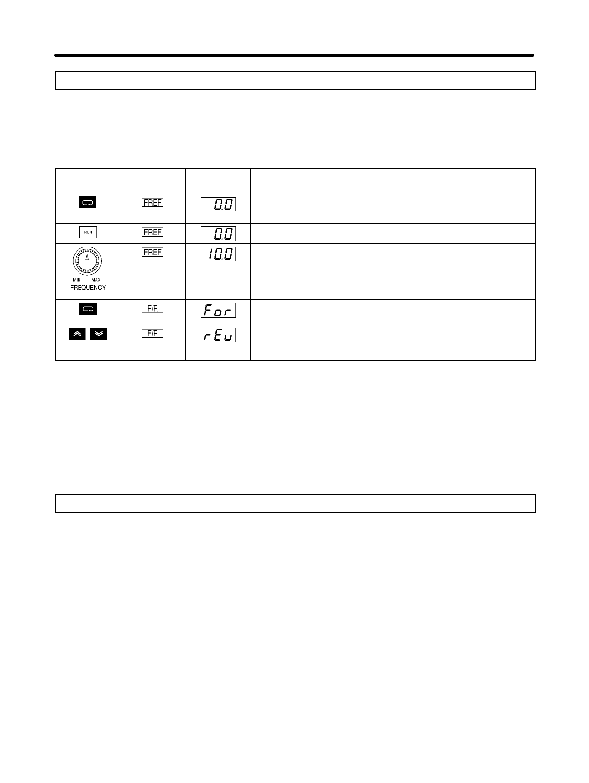
Test Run
Chapter 4
5 No-load Operation
• Start the no-load motor (i.e., not connected to the mechanical system) using the Digital Operator.
Note Before operating the Digital Operator, check that the FREQ adjuster is set to MIN.
H Forward/Reverse Rotation with the Digital Operator
Key
sequence
• After changing the frequency reference or the rotation direction, check that there is no vibration or
abnormal sound from the motor.
• Check that no faults have occurred in the Inverter during operation.
Indicator Display
example
Explanation
Press the Mode Key to turn on the FREF indicator.
Monitors the frequency reference.
Press the RUN Key. The RUN Indicator will be lit.
Turn the FREQ adjuster clockwise slowly.
The monitored frequency reference will be displayed.
The motor will start rotating in the forward direction according
to the frequency reference.
Press the MODE Key to turn on the F/R indicator.
“For” will be displayed.
Use the Increment or Decrement Key to change the direction of
motor rotation. The direction of motor rotation selected will be
enabled when the display is changed after the Key is pressed.
H Stopping the Motor
• On completion of operating the motor in the no-load state in the forward or reverse direction, press the
STOP/RESET Key. The motor will stop.
6 Actual Load Operation
• After checking the operation with the motor in no-load status, connect the mechanical system and
operate with an actual load.
Note Before operating the Digital Operator, check that the FREQ adjuster is set to MIN.
H Connecting the System
• After confirming that the motor has stopped completely, connect the mechanical system.
• Be sure to tighten all the screws when fixing the motor axis in the mechanical system.
H Operation Using the Digital Operator
• In case a fault occurs during operation, make sure the Stop Key on the Digital Operator is easily accessible.
• Use the Digital Operator in the same way as no-load operation.
• First set the frequency reference to a low speed of one tenth the normal operating speed.
4-7
Page 81

Test Run
Chapter 4
H Checking the Operating Status
• Having checked that the operating direction is correct and that the machine is operating smoothly at
slow speed, increase the frequency reference.
• After changing the frequency reference or the rotation direction, check that there is no vibration or
abnormal sound from the motor. Check the monitor display (IOUT or multi-function monitor U03) to
ensure that the output current is not becoming excessive.
4-8
Page 82
5
Chapter 5
Basic Operation
5-1 Initial Settings
5-2 V/f Control
5-3 Setting the Local/Remote Mode
5-4 Selecting the Operation Command
5-5 Setting the Frequency Reference
5-6 Setting the Acceleration/Deceleration Time
5-7 Selecting the Reverse Rotation-prohibit
5-8 Selecting the Interruption Mode
5-9 Multi-function I/O
5-10 Analog Monitor Output
Page 83
Basic Operation
This section explains the basic settings required to operate and stop the Inverter.
The settings of parameters described here will be sufficient for simple Inverter operations.
First, make these basic settings, then skip to the explanations of those special functions,
even when your application requires special functions, such as stall prevention, carrier
frequency setting, overtorque detection, torque compensation, slip compensation. Refer to Chapter 6 Advanced Operation.
Chapter 5
5-1 Initial Settings
• The following initial settings are required.
Parameter Write-prohibit Selection/Parameter Initialization (n01): Set n01 to 1 so that n01 through
n79 can be set or displayed.
Rated Motor Current (n32): Check the rated current on the motor nameplate and set the parameter.
H Setting the Parameter Write-prohibit Selection/Parameter Initialization
(n01)
• Set n01 to 1 so that n01 through n79 can be set or displayed.
n01
Setting
range
Note This parameter makes it possible to write-prohibit parameters, change the parameter set or dis-
Parameter Write-prohibit Selection/Parameter
Initialization
0, 1, 5, 6, 8, 9 Unit of
setting
played range, or initialize all parameters to default values.
1 Default setting 1
Changes during
operation
No
Set Values
Value Description
0 Only n01 can be displayed and set. The n02 through n79 parameters can be displayed only.
1 The n01 through n79 parameters can be displayed and set.
5 Enables continuous operation. (Parameters n01 to n79 can be set or monitored.)
6 Only the error log memory is cleared.
8 Enables the initialization of all parameters in 2-wire sequence so that the parameters will
return to default values.
9 Enables the initialization of all parameters in 3-wire sequence.
Note With settings 0 or 1, operation commands are ignored in Program Mode. (Refer to 3-1-2 Drive
Mode and Program Mode.) Normally, use a setting of 0 or 1.
H Setting the Rated Motor Current (n32)
Set the rated motor current (n32) in order to prevent the motor from burning due to overloading.
Check the rated current on the motor nameplate and set the parameter.
This parameter is used for the electronic thermal function for motor overload detection (OL1). By setting
the correct parameter, the overloaded motor will be protected from burning.
5-2
Page 84

Basic Operation
Chapter 5
n32
Setting
range
Rated Motor Current Changes during
operation
0.0% to 120% (A) of rated output
current of Inverter
Unit of
setting
0.1 A Default setting (see note
No
1)
Note 1. The standard rated current of the maximum applicable motor is the default rated motor cur-
rent.
Note 2. Motor overload detection (OL1) is disabled by setting the parameter to 0.0.
5-3
Page 85
Basic Operation
Chapter 5
5-2 V/f Control
H Setting the V/f Patterns (n09 to n15)
• Set the V/f pattern so that the motor output torque is adjusted to the required load torque.
• The 3G3JV incorporates an automatic torque boost function. Therefore, a maximum of 150% torque
can be output at 3 Hz without changing the default settings. Check the system in trial operation and
leave the default settings as they are if no torque characteristic changes are required.
n09
Setting
range
n10
Setting
range
n11
Setting
range
n12
Setting
range
n13
Setting
range
Maximum Frequency (FMAX) Changes during
operation
50.0 to 400 (Hz) Unit of
setting
Maximum Voltage (VMAX) Changes during
1 to 255 (V) (See note 2.) Unit of
setting
Maximum Voltage Frequency (FA) Changes during
0.2 to 400 (Hz) Unit of
setting
Middle Output Frequency (FB) Changes during
0.1 to 399 (Hz) Unit of
setting
Middle Output Frequency Voltage (VC) Changes during
1 to 255 (V) (See note 2.) Unit of
setting
0.1 Hz
(See note 1.)
1 V Default setting 200 (See
0.1 Hz
(See note 1.)
0.1 Hz
(See note 1.)
1 V Default setting 12 (See
Default setting 60.0
operation
operation
Default setting 60.0
operation
Default setting 1.5
operation
No
No
note 2.)
No
No
No
note 2.)
n14
Setting
range
n15
Setting
range
Minimum Output Frequency (FMIN) Changes during
operation
0.1 to 10.0 (Hz) Unit of
setting
Minimum Output Frequency Voltage (VMIN) Changes during
1 to 50 (V) (See note 2.) Unit of
setting
0.1 Hz Default setting 1.5
operation
1 V Default setting 12 (See
No
No
note 2.)
Note 1. Values will be set in 0.1-Hz increments if the frequency is less than 100 Hz and 1-Hz incre-
ments if the frequency is 100 Hz or greater.
5-4
Page 86
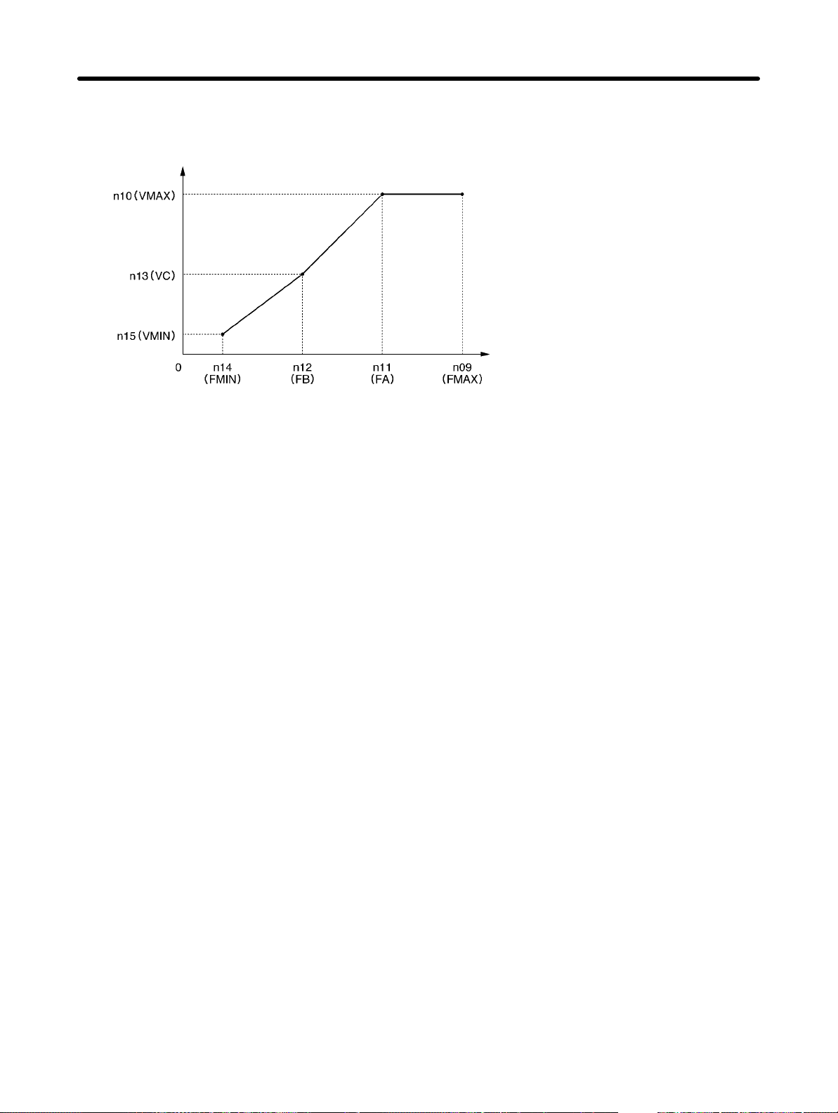
Basic Operation
Chapter 5
Note 2. With 400-V Inverters, the values for the upper limit of setting ranges and the default settings
will be twice those given in the above table.
Output voltage
(V)
Note 1. Set the parameters so that the fol-
lowing condition will be satisfied.
n14 x n12 < n11 x n09
Note 2. The value set in n13 will be ignored if
parameters n14 and n12 are the
same in value.
Frequency (Hz)
• Set the rated motor input frequency to the maximum voltage frequency (FMAX) while the rated motor
input voltage is set to the maximum output voltage (VMAX).
• The vertical-axis load or the load with high viscous friction may require high torque at low speed. If the
torque is insufficient at low speed, increase the voltage in the low-speed range by 1 V, provided that no
overload (OL1 or OL2) is detected. If an overload is detected, decrease the set values or consider the
use of an Inverter model with a higher capacity.
• The required torque of fan or pump control increases in proportion to the square of the speed. By setting a quadratic V/f pattern to increase the voltage in the low-speed range, the power consumption of
the system will increase.
5-5
Page 87

Basic Operation
5-3 Setting the Local/Remote Mode
The 3G3JV operates in local or remote mode. The following description provides information on these modes and how to select them.
H Basic Concept
Operation mode Basic concept Description
Remote The Inverter in a system
operates according to the
control signal of the host
controller.
Local The Inverter in a system
operates independently in this
mode so that the Inverter can
be checked independently.
RUN Command
Selectable from two types and set in n02.
Frequency Reference
Selectable from five types and set in n03.
RUN Command
Starts with the RUN Key of the Digital Operator
and stops with the STOP/RESET Key.
Frequency Reference
Set with the Digital Operator or the FREQ
adjuster.
Set with frequency reference selection in local
mode in n07.
Chapter 5
H Local/Remote Selection Methods
• The following two selection methods are available to set the Inverter to local or remote mode. While
the operation command is being input, however, the Inverter cannot be set to local mode from remote
mode or vice versa.
S Select the mode with the LO/RE Key of the Digital Operator.
S Set any one of multi-function inputs 1 through 4 (n36 through n39) to 17 to set the Inverter to local
mode with control input turned ON.
Note If the above setting is made, mode selection will be possible only with multi-function input, and not
with the Digital Operator.
• The Inverter always goes into remote mode when the power is turned ON. Therefore, to operate immediately after power-up, set up the RUN command and frequency reference settings in remote mode
in advance.
5-6
Page 88
Basic Operation
Chapter 5
5-4 Selecting the Operation Command
The following description provides information on how to input operation commands to
start or stop the Inverter or change the direction of rotation of the Inverter.
Three types of command input methods are available. Select either one of them according to the application.
H Selecting the Operation Mode (n02)
• Select the method of operation mode input to start or stop the Inverter.
• The following method is enabled in remote mode only. The command can be input through key se-
quences on the Digital Operator.
n02
Setting
range
Operation Command Selection Changes during
operation
0 to 2 Unit of
setting
1 Default setting 0
No
Set Values
Value Description
0 The RUN and STOP/RESET Keys of the Digital Operator are enabled.
1 Multi-function input in 2- or 3-wire sequence through the control circuit terminals is enabled.
2 Operation commands via RS-422/485 communications are enabled.
H Selecting the STOP/RESET Key Function (n06)
• When parameter n02 is set to 1, set whether or not to use the STOP/RESET Key of the Digital Operator to stop the Inverter in remote mode. The STOP/RESET Key is always enabled in local mode regardless of the setting in n02.
n06
Setting
range
STOP Key Function Selection Changes during
operation
0, 1 Unit of
setting
1 Default setting 0
No
Set Values
Value Description
0 The STOP/RESET Key of the Digital Operator is enabled.
1 The STOP/RESET Key of the Digital Operator is disabled. This setting is available only when
the Digital Operator is selected for operation command input.
5-7
Page 89
Basic Operation
Chapter 5
5-5 Setting the Frequency Reference
5-5-1 Selecting the Frequency Reference
The following description provides information on how to set the frequency reference in
the Inverter. Select the method according to the operation mode.
Remote mode: Select and set one out of six frequency references in n03.
Local mode: Select and set one out of two frequency references in n07.
H Selecting the Frequency Reference (n03) in Remote Mode
• Select the input method of frequency references in remote mode.
• Five frequency references are available in remote mode. Select one of them according to the applica-
tion.
n03
Setting
range
Frequency Reference Selection Changes during
operation
0 to 4, 6 Unit of
setting
1 Default setting 0
No
Set Values
Value Description
0 The FREQ adjuster of the Digital Operator is enabled. (see note 1)
1 Frequency reference 1 (n21) is enabled.
2 The frequency reference control terminal (for 0- to 10-V input) is enabled. (see note 2)
3 The frequency reference control terminal (for 4- to 20-mA current input) is enabled. (see note
3)
4 The frequency reference control terminal (for 0- to 20-mA current input) is enabled. (see note
3)
6 The frequency reference via RS-422/485 communications is enabled.
Note 1. The maximum frequency (FMAX) is set when the FREQ adjuster is set to MAX.
Note 2. The maximum frequency (FMAX) is set with 10 V input.
Note 3. The maximum frequency (FMAX) is set with 20 mA input, provided that SW8 on the control
PCB is switched from V to I.
• The frequency reference set in n03 works as frequency reference 1 when the Inverter is in multi-step
speed operation. The set values in n22 through n28 for frequency references 2 through 8 are enabled.
H Selecting the Frequency Reference (n07) in Local Mode
• Select the input method of frequency references in local mode.
• Two frequency references are available in local mode. Select one of them according to the application.
Setting
range
5-8
n07
Frequency Reference Selection in Local Mode Changes during
operation
0, 1 Unit of
setting
1 Default setting 0
No
Page 90
Basic Operation
Chapter 5
Set Values
Value Description
0 The FREQ adjuster of the Digital Operator is enabled. (see note 1)
1 Key sequences on the Digital Operator are enabled. (see note 2)
Note 1. The maximum frequency (FMAX) is set when the FREQ adjuster is set to MAX.
Note 2. The frequency reference can be set with key sequences while the FREF indicator is lit or with
the set value in n21 for frequency reference 1. In either case, the value is set in n21.
5-5-2 Upper and Lower Frequency Reference Limits
Regardless of the methods of operation mode and frequency reference input, the upper
and lower frequency reference limits can be set.
H Setting the Frequency Reference Upper and Lower Limits (n30 and
n31)
• Set the upper and lower frequency reference limits as percentage based on the maximum frequency
as 100%.
n30
Setting
range
n31
Setting
range
Frequency Reference Upper Limit Changes during
operation
0% to 110%
(Max. frequency = 100%)
Frequency Reference Lower Limit Changes during
0% to 110%
(Max. frequency = 100%)
Unit of
setting
Unit of
setting
1% Default setting 100
operation
1% Default setting 0
No
No
Note If n31 is set to a value less than the minimum output frequency (FMIN), the Inverter will have no
output when a frequency reference less than the minimum output frequency input is ON.
5-5-3 Adjusting the Analog Input
Input characteristic adjustments may be necessary for analog frequency references to
be input. At that time, use the following parameters for gain, bias, and filter time parameter adjustments.
H FR Terminal Adjustments for Frequency Reference Input
D Gain and Bias Settings (n41 and n42)
• Set the input characteristics of analog frequency references in n41 (for the frequency reference gain)
and n42 (for the frequency reference bias).
• Set the frequency of maximum analog input (10 V or 20 mA) in n41 as percentage based on the maximum frequency as 100%.
• Set the frequency of minimum analog input (0 V, 0 mA, or 4 mA) in n42 as percentage based on the
maximum frequency as 100%.
n41
Setting
range
Frequency Reference Gain Changes during
operation
0% to 255%
(Max. frequency = 100%)
Unit of
setting
1% Default setting 100
Yes
5-9
Page 91
Basic Operation
Chapter 5
n42
Setting
range
Frequency Reference Bias Changes during
operation
–99% to 99%
(Max. frequency = 100%)
Unit of
setting
1% Default setting 0
Yes
D Analog Frequency Reference Filter Time (n43)
• The digital filter with a first-order lag can be set for analog frequency references to be input.
• This setting is ideal if the analog input signal changes rapidly or the signal is subject to noise interfer-
ence.
• The larger the set value is, the slower the response speed will be.
n43
Setting
range
Analog Frequency Reference Filter Time Changes during
operation
0.00 to 2.00 (s) Unit of
setting
0.01 s Default setting 0.10
No
5-5-4 Setting Frequency References through Key Sequences
The following description provides information on parameters related to frequency reference settings through key sequences on the Digital Operator
H Setting Frequency References 1 through 8 and the Inching Frequency
Command (n21 through n28 and n29)
A total of nine frequency references (frequency references 1 through 8) and an inching frequency command can be set together in the Inverter.
D Setting Frequency References 1 through 8 (n21 through n28)
n21
Setting
range
n22
Setting
range
n23
Setting
range
n24
Setting
range
Frequency Reference 1 Changes during
operation
0.0 to max. frequency Unit of
setting
Frequency Reference 2 Changes during
0.0 to max. frequency Unit of
setting
Frequency Reference 3 Changes during
0.0 to max. frequency Unit of
setting
Frequency Reference 4 Changes during
0.0 to max. frequency Unit of
setting
0.01 Hz (see
note 1)
0.01 Hz (see
note 1)
0.01 Hz (see
note 1)
0.01 Hz (see
note 1)
Default setting 6.0
operation
Default setting 0.0
operation
Default setting 0.0
operation
Default setting 0.0
Yes
Yes
Yes
Yes
Setting
range
5-10
n25
Frequency Reference 5 Changes during
operation
0.0 to max. frequency Unit of
setting
0.01 Hz (see
note 1)
Default setting 0.0
Yes
Page 92
Basic Operation
Chapter 5
n26
Setting
range
n27
Setting
range
n28
Setting
range
Frequency Reference 6 Changes during
operation
0.0 to max. frequency Unit of
setting
Frequency Reference 7 Changes during
0.0 to max. frequency Unit of
setting
Frequency Reference 8 Changes during
0.0 to max. frequency Unit of
setting
0.01 Hz (see
note 1)
0.01 Hz (see
note 1)
0.01 Hz (see
note 1)
Default setting 0.0
operation
Default setting 0.0
operation
Default setting 0.0
Yes
Yes
Yes
Note 1. Values will be set in 0.1-Hz increments if the frequency is less than 100 Hz and 1-Hz incre-
ments if the frequency is 100 Hz or over.
Note 2. Frequency reference 1 is enabled with n03 for frequency reference selection set to 1.
Note 3. Frequency references 2 through 8 are enabled by setting multi-step speed references 1, 2,
and 3 in n36 through n39 for multi-function input. Refer to the following table for the relationship between multi-step speed references 1 through 3 and frequency references 1 through 8.
Frequency reference Multi-step speed
reference 1
(Set value: 6)
Frequency reference 1 OFF OFF OFF
Frequency reference 2 ON OFF OFF
Frequency reference 3 OFF ON OFF
Frequency reference 4 ON ON OFF
Frequency reference 5 OFF OFF ON
Frequency reference 6 ON OFF ON
Frequency reference 7 OFF ON ON
Frequency reference 8 ON ON ON
Multi-step speed
reference 2
(Set value: 7)
Multi-step speed
reference 3
(Set value: 8)
No multi-step speed reference 3 settings will be required if only frequency references 1 through 4 are
used, for example. Any multi-step speed reference not set is regarded as turned-OFF input.
D Setting the Inching Frequency Command (n29)
• The inching frequency command must be set as multi-function input in order to use the inching frequency command.
n29
Setting
range
Inching Frequency Command Changes during
operation
0.0 to max. frequency Unit of
setting
0.01 Hz (see
note 1)
Default setting 6.0
Yes
Note 1. The value will be set in 0.1-Hz increments if the frequency is less than 100 Hz and 1-Hz incre-
ments if the frequency is 100 Hz or over.
5-11
Page 93
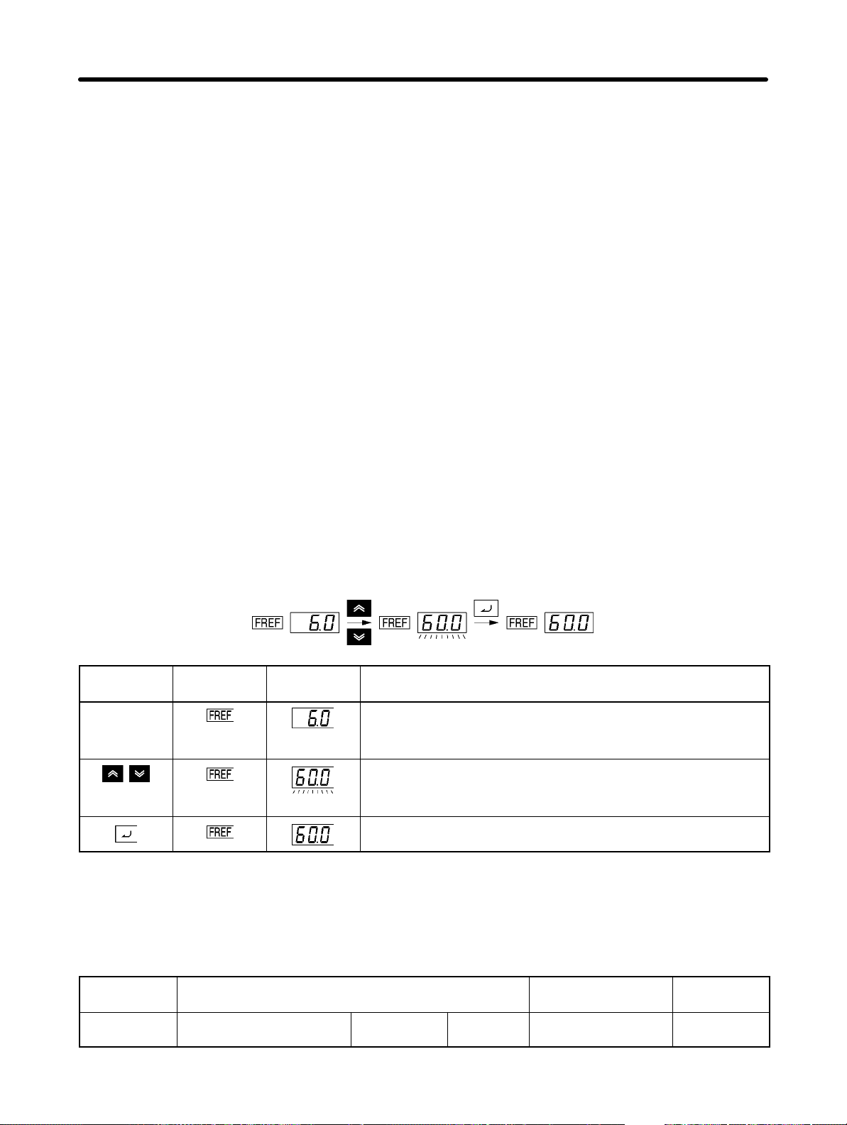
Basic Operation
Chapter 5
Note 2. In order to use the inching frequency command, one of the n36 through n39 parameters for
multi-function input must be set to 10 as an inching frequency command. Parameter n29 is
selectable by turning on the multi-function input set with the inching frequency command. The
inching frequency command takes precedence over the multi-step speed reference (i.e.,
when the inching frequency command is ON, all multi-step speed reference input will be ignored).
H Setting the Frequency Reference with the FREF Indicator Lit
• The frequency reference can be set while the FREF indicator of the Digital Operator is lit in the following cases.
S Parameter n03 for frequency reference selection is set to 1, which enables frequency reference 1,
and the Inverter is in remote mode.
S Parameter n07 for frequency selection in local mode is set to 1, which enables key sequences on
the Digital Operator, and the Inverter is in local mode.
S Frequency references 2 through 8 are set with multi-step speed reference input.
• The frequency reference can be changed, even during operation.
• When the frequency reference is changed while the FREF indicator is lit, the corresponding parameter
is changed simultaneously. For example, if frequency reference 2 has been selected with multi-function input (a multi-step speed reference), the set value in n22 (for frequency reference 2) will be
changed simultaneously when the frequency reference is changed while the FREF indicator is lit.
• Take the following default steps, for example, to change the frequency reference with the FREF indicator lit.
Key
sequence
Indicator Display
example
Explanation
Power On
Note If the FREF indicator has not been lit, press the Mode Key
repeatedly until the FREF indicator is lit.
Use the Increment or Decrement Key to set the frequency
reference.
The data display will flash while the frequency reference is set.
Press the Enter Key so that the set value will be entered and
the data display will be lit.
D Setting the Key Sequential Frequency (n08)
• The Enter Key need not be pressed when changing the setting in n08. In that case, the frequency
reference will change when the set value is changed with the Increment or Decrement Key while the
data display is continuously lit.
Setting
range
5-12
n08
Key Sequential Frequency Setting Changes during
operation
0, 1 Unit of
setting
1 Default setting 0
No
Page 94

Basic Operation
Set Values
Value Description
0 Enter Key enabled (The set value is entered with the Enter Key pressed.)
1 Enter Key disabled (The set value set is entered immediately.)
Chapter 5
5-13
Page 95
Basic Operation
Chapter 5
5-6 Setting the Acceleration/Deceleration Time
The following description provides information on parameters related to acceleration
and deceleration time settings.
Trapezoidal and S-shape acceleration and deceleration are available. Using the Sshape characteristic function for acceleration and deceleration can reduce shock to the
machinery when stopping or starting.
H Setting the Acceleration/Deceleration Time (n16 through n19)
• Two acceleration times and two deceleration times can be set.
• The acceleration time is the time required to go from 0% to 100% of the maximum frequency and the
deceleration time is the time required to go from 100% to 0% of the maximum frequency. The actual
acceleration or deceleration time is obtained from the following formula.
Acceleration/Deceleration time = (Acceleration/Deceleration time set value)
× (Frequency reference value) ÷ (Max. frequency)
Acceleration time 2 and deceleration time 2 are enabled by setting 11 for acceleration/deceleration time
selection in any of the n36 through n39 parameters for multi-function input.
Deceleration time 2 is also enabled by emergency-stop settings 19, 20, 21, and 22 in any of the n36,
n37, n38, and n39 parameters for multi-function input with n04 for interruption mode selection set to 0
(i.e., deceleration stop).
n16
Setting
range
n17
Setting
range
n18
Setting
range
n19
Unit of
setting
Acceleration time 1 Changes during
operation
0.0 to 999 (s) Unit of
setting
Deceleration Time 1 Changes during
0.0 to 999 (s) Unit of
setting
Acceleration Time 2 Changes during
0.0 to 999 (s) Unit of
setting
Deceleration Time 2 Changes during
0.0 to 999 (s) Unit of
setting
0.1 s
(see note)
0.1 s
(see note)
0.1 s
(see note)
0.1 s
(see note)
Default setting 10.0
operation
Default setting 10.0
operation
Default setting 10.0
operation
Default setting 10.0
Yes
Yes
Yes
Yes
Note Values will be set in 0.1-Hz increments if the frequency is less than 100 Hz and 1-Hz increments if
the frequency is 100 Hz or over.
5-14
Page 96
Basic Operation
Chapter 5
H S-shape Acceleration/Deceleration Characteristic (n20)
• Trapezoidal and S-shape acceleration and deceleration are available. Using the S-shape characteristic function for acceleration and deceleration can reduce shock to the machinery when stopping or
starting.
• Any one of three S-shape acceleration/deceleration times (0.2, 0.5, and 1.0 s) is selectable.
n20
Setting
range
S-shape Acceleration/Deceleration Characteristic Changes during
operation
0 to 3 Unit of
setting
1 Default setting 0
No
Set Values
Value Description
0 No S-shape acceleration/deceleration characteristic (Trapezoidal acceleration/deceleration)
1 S-shape acceleration/deceleration characteristic time is 0.2 s
2 S-shape acceleration/deceleration characteristic time is 0.5 s
3 S-shape acceleration/deceleration characteristic time is 1.0 s
Note When the S-shape acceleration/deceleration characteristic time is set, the acceleration and de-
celeration times will be lengthened according to the S-shape at the beginning and end of acceleration/deceleration.
5-15
Page 97
Basic Operation
5-7 Selecting the Reverse Rotation-prohibit
This parameter is used to specify whether to enable or disable the reverse rotation command sent to the Inverter from the control circuit terminals or Digital Operator.
The parameter should be set to “not accept” when the Inverter is applied to systems that
prohibit the reverse rotation of the Inverter.
H Selecting the Reverse Rotation-prohibit (n05)
Chapter 5
n05
Setting
range
Reverse Rotation-prohibit Selection Changes during
0, 1 Unit of
setting
Set Values
Value Description
0 Accept
1 Not accept
No
operation
1 Default setting 0
5-16
Page 98
Basic Operation
5-8 Selecting the Interruption Mode
This parameter is used to specify the interruption mode when the STOP command is
input.
The Inverter either decelerates or coasts to a stop according to the interruption mode
selection.
H Selecting the Interruption Mode (n04)
Chapter 5
n04
Setting
range
Interruption Mode Selection Changes during
operation
0, 1 Unit of
setting
1 Default setting 0
No
Set Values
Value Description
0 Frequency deceleration stop (See notes 1 and 2.)
1 Free running (See note 3.)
Note 1. The Inverter will decelerate to stop according to the setting in n17 for deceleration time 1 if any
of the n36 through n39 parameters for multi-function input is not set to 11 for acceleration/deceleration time selection. If any one of the n36 through n39 multi-function input parameters is
set to acceleration/deceleration time selection, the Inverter will decelerate to stop according
to the selected setting of deceleration time when the STOP command is input.
Note 2. If the RUN signal is input again during a deceleration stop, deceleration will be stopped at the
point of the input and acceleration will proceed at that frequency.
Note 3. Do not input a RUN signal during a free-running stop if the motor’s rotation speed is not suffi-
cient slowed. If a RUN signal is input under these conditions, a main circuit overvoltage (OV)
or overcurrent (OC) will be detected.
To restart a free-running motor, set a speed search command in one of the multi-function inputs 1 to 4 (n36 to n39), use the speed search to detect the speed of the free running motor,
and then accelerate smoothly.
5-17
Page 99
Note Refer to 554 Setting the Frequency References through Key
qy
Basic Operation
5-9 Multi-function I/O
5-9-1 Multi-function Input
The 3G3JV incorporates four multi-function input terminals (S2 through S5). Inputs into
these terminals have a variety of functions according to the application.
H Multi-function Input (n36 through n39)
Chapter 5
n36
Setting
range
n37
Setting
range
n38
Setting
range
n39
Setting
range
Multi-function Input 1 (S2) Changes during
operation
2 to 8, 10 to 22
(see note)
Multi-function Input 2 (S3) Changes during
0, 2 to 8, 10 to 22 (see
note)
Multi-function Input 3 (S4) Changes during
2 to 8, 10 to 22
(see note)
Multi-function Input 4 (S5) Changes during
2 to 8, 10 to 22, 34, 35
(see note)
Unit of
setting
Unit of
setting
Unit of
setting
Unit of
setting
1 Default setting 2
operation
1 Default setting 5
operation
1 Default setting 3
operation
1 Default setting 6
Note Do not set values outside the above setting ranges.
Set Values
Value Function Description
0 Forward/Reverse rotation
command
2 Reverse/Stop Reverse rotation command (2-wire sequence)
3 External fault (NO)
4 External fault (NC)
5 Fault reset ON: Fault reset (disabled while RUN command is input)
6 Multi-step speed
reference 1
7 Multi-step speed
reference 2
8 Multi-step speed
reference 3
3-wire sequence (to be set in n37 only)
By setting n37 to 0, the set value in n36 is ignored and the
following setting are forcibly made.
S1: RUN input (RUN when ON)
S2: STOP input (STOP when OFF)
S3: Forward/Reverse rotation command
(OFF: Forward; ON: Reverse)
ON: External fault (FPj detection: j is a terminal number)
OFF: External fault (EFj detection: j is a terminal number)
Signals to select frequency references 2 through 8.
Note Refer to 5-5-4 Setting the Frequency References through Key
Sequences for the relationship between multi-step speed ref-
erences and frequency references.
Note Any multi-step speed reference not set is regarded as turned-
OFF input.
No
No
No
No
5-18
Page 100
gyp
Basic Operation
Value DescriptionFunction
10 Inching frequency
command
11 Acceleration/Deceleration
time selection
12 External base block
command (NO)
13 External base block
command (NC)
14 Search command
(Searching starts from
maximum frequency)
15 Search command
(Searching starts from
preset frequency)
16 Acceleration/Decelera-
tion-prohibit command
17 Local or remote selection ON: Local mode (operated with the Digital Operator)
18 Communications or
remote selection
19 Emergency stop fault
(NO)
20 Emergency stop alarm
(NO)
21 Emergency stop fault
(NC)
22 Emergency stop alarm
(NC)
34 Up or down command Up or down command (set in n39 only)
35 Self-diagnostic test ON: RS-422/485 communications self-diagnostic test (set in n39
ON: Inching frequency command (taking precedence over the
multi-step speed reference)
ON: Acceleration time 2 and deceleration time 2 are selected.
ON: Output shut off (while motor coasting to a stop and “bb”
flashing)
OFF: Output shut off (with motor free running and “bb” flashing)
ON: Speed search (Searching starts from n09)
ON: Speed search
ON: Acceleration/Deceleration is on hold (running at parameter
frequency)
Note After this setting is made, mode selection with the Digital Oper-
ator is not possible.
ON: RS-422/485 communications input is enabled.
OFF: The settings of n02 and n03 are enabled.
The Inverter stops according to the setting in n04 for interruption
mode selection with the emergency stop input turned ON.
n04 set to 0: Decelerates to stop at deceleration time 2 set in
n19. n04 set to 1: Coasts to a stop.
Note NO: Emergency stop with the contact closed.
NC: Emergency stop with the contact opened.
Note Fault: Fault output is ON and reset with RESET input. Alarm
output is ON (no reset required).
Note “STP” is displayed (lit with fault input ON and flashes with alarm
input ON)
By setting n39 to 34, the set value in n38 is ignored and the
following settings are forcibly made.
S4: Up command S5: Down command
Note It is impossible to set the up or down command and multi-step
speed references 1 through 3 together.
Note For up and down command functions in detail, refer to 6-7-7
UP/DOWN Command Frequency Memory (n62).
only)
Chapter 5
5-19
 Loading...