

Page 1
Cat. No. I126E-EN-04
ZX-T Series
SX-F
Instruction Manual
Page 2

Page 3

Omron SX-F
INSTRUCTION MANUAL - ENGLISH
Valid from Software version 4.42
Document number: I126E-EN-04
Document name : Omron SX-F inverter manual
Date of release: 02-2021
© OMRON, 2021
All rights reserved. No part of this publication may be reproduced, stored
in a retrieval system, or transmitted, in any form, or by any means,
mechanical, electronic, photocopying, recording, or otherwise, without
the prior written permission of OMRON.
No patent liability is assumed with respect to the use of the information
contained herein. Moreover, because OMRON is constantly striving to
improve its high-quality products, the information contained in this
manual is subject to change without notice. Every precaution has been
taken in the preparation of this manual.
Nevertheless, OMRON assumes no responsibility for errors or omissions.
Neither is any liability assumed for damages resulting from the use of the
information contained in this publication.
Page 4

Page 5
Safety Instructions
Congratulations for choosing a product from Omron!
Before you begin with installation, commissioning or
powering up the unit for the first time it is very important
that you carefully study this Instruction manual.
Following symbols can appear in this instruction or on the
product itself. Always read these first before continuing.
NOTE: Additional information as an aid to avoid
problems.
CAUTION!
Failure to follow these instructions can
!
result in malfunction or damage to the AC
drive.
Warning!
Failure to follow these instructions can
result in serious injury to the user in
addition to serious damage to the AC
drive.
HOT SURFACE!
Failure to follow these instructions can
result in injury to the user.
Handling the AC drive
Installation, commissioning, demounting, taking
measurements, etc, of or on the AC drive may only be
carried out by personnel technically qualified for the task.
A number of national, regional and local regulations govern
handling, storage and installation of the equipment. Always
observe current rules and legislation.
Opening the AC drive
Precautions to be taken with a
connected motor
If work must be carried out on a connected motor or on the
driven machine, the mains voltage must always be
disconnected from the AC drive first. Wait at least 7minutes
before starting work.
Earthing
The AC drive must always be earthed via the mains safety
earth connection.
Earth leakage current
CAUTION!
This AC drive has an earth leakage current
!
which does exceed 3.5 mA AC. Therefore
the minimum size of the protective earth
conductor must comply with the local safety
regulations for high leakage current equipment which
means that according to the standard IEC61800-5-1
the protective earth connection must be assured by
one of following conditions:
PE conductor cross-sectional area shall for phase
cable size <
Al) or use a second PE conductor with same area as
original PE conductor.
For cable size above 16 mm
equal to 35mm
sectional area shall be at least 16mm
(6 AWG).
For cables >35 mm2 (2 AWG) the PE conductor crosssectional area should be at least 50 % of the used
phase conductor.
When the PE conductor in the used cable type is not
in accordance with the above mentioned crosssectional area requirements, a separate PE
conductor should be used to establish this.
16 mm2 (6 AW G) be >10 mm2 Cu (16 mm2
2
2
(2 AWG) the PE conductor cross-
(6 AWG) but smaller or
2
WARNING!
Always switch off the mains voltage before
opening the AC drive and wait at least 7
minutes to allow the capacitors to
discharge.
Always take adequate precautions before opening the AC
drive. Although the connections for the control signals and
the switches are isolated from the main voltage, do not
touch the control board when the AC drive is switched on.
Residual current device (RCD)
compatibility
This product cause a DC current in the protective
conductor.
for protection in case of direct or indirect contact, only a
Type B RCD is allowed on the supply side of this product.
Use RCD of 300 mA minimum.
Where a residual current device (RCD) is used
EMC Regulations
Incorrect connection
The AC drive is not protected against incorrect connection
of the mains voltage, and in particular against connection of
the mains voltage to the motor outlets U, V and W. The AC
drive can be damaged in this way. Risk for personal injury.
Omron, I126E-EN-04 1
In order to comply with the EMC Directive, it is absolutely
necessary to follow the installation instructions. All
installation descriptions in this manual follow the EMC
Directive.
Page 6

Mains voltage selection
The AC drive may be ordered for use with the mains voltage
range listed below.
SX-F48: 230-480 V
SX-F69: 500-690 V
Heat warning
HOT SURFACE!
Be aware of specific parts on the AC drive
having high temperature.
Voltage tests (Megger)
Do not carry out voltage tests (Megger) on the motor, before
all the motor cables have been disconnected from the AC
drive.
Condensation
If the AC drive is moved from a cold (storage) room to a
room where it will be installed, condensation can occur.
This can result in sensitive components becoming damp. Do
not connect the mains voltage until all visible dampness has
evaporated.
Power factor capacitors for
improving cos
Remove all capacitors from the motor and the motor outlet.
ϕ
Precautions during Autoreset
When the automatic reset is active, the motor will restart
automatically provided that the cause of the trip has been
removed. If necessary take the appropriate precautions.
DC-link residual voltage
WARNING!
After switching off the mains supply,
dangerous voltage can still be present in
the AC drive. When opening the AC drive
for installing and/or commissioning
activities wait at least 7 minutes. In case of
malfunction a qualified technician should check the
DC-link or wait for one hour before dismantling the
AC drive for repair.
Tra ns po rt
To avoid damage, keep the AC drive in its original
packaging during transport. This packaging is specially
designed to absorb shocks during transport.
IT Mains supply
The AC drives can be modified for an IT mains supply,
(non-earthed neutral), please contact your supplier for
details.
Alarms
Never disregard an alarm. Always check and remedy the
cause of an alarm.
2 Omron, I126E-EN-04
Page 7

Contents
Safety Instructions.................................. 1
Contents................................................. 3
1. Introduction ............................................ 7
1.1 Delivery and unpacking .................................... 7
1.2 Using of the instruction manual ........................ 7
1.2.1 Instruction manuals for optional equipment ....... 7
1.3 Warranty ......................................................... 8
1.4 Type code number ........................................... 9
1.5 Standards ..................................................... 10
1.5.1 Product standard for EMC............................... 10
1.6 Dismantling and scrapping ............................. 11
1.6.1 Disposal of old electrical and electronic equipment
11
1.7 Glossary ....................................................... 12
1.7.1 Abbreviations and symbols ............................. 12
1.7.2 Definitions .................................................... 12
2. Mounting .............................................. 13
2.1 Lifting instructions ......................................... 13
2.2 Stand-alone units .......................................... 14
2.2.1 Cooling ......................................................... 14
2.2.2 Mounting schemes ........................................ 15
2.3 Cabinet mounting .......................................... 22
2.3.1 Cooling ......................................................... 22
2.3.2 Recommended free space in front of cabinet ... 22
2.3.3 Mounting schemes, cabinets.......................... 23
3. Installation ........................................... 25
3.1 Before installation ......................................... 25
3.1.1 Remove/open front cover............................... 25
3.1.2 Remove/open the lower front cover on Frame size
E2, F2 and FA2 (IP20/21) .............................. 26
3.2 Cable connections for small and medium frame siz-
es ................................................................ 26
3.2.1 Mains cables................................................. 26
3.2.2 Motor cables ................................................. 29
3.3 Connection of motor and mains cables for larger
frame sizes ................................................... 32
3.3.1 Connection of mains and motor cables on IP20
modules ....................................................... 34
3.4 Cable specifications....................................... 36
3.4.1 Stripping lengths ........................................... 36
3.4.2 Fuse data...................................................... 38
3.4.3 Cable connection data for mains, motor and PE ca-
bles according to IEC ratings .......................... 39
3.4.4 Cable connection data for mains, motor and PE ca-
bles according to NEMA ratings ...................... 43
3.5 Thermal protection on the motor ..................... 45
3.6 Motors in parallel .......................................... 45
4. Control Connections.............................. 47
4.1 Control board ................................................ 47
4.2 Terminal connections..................................... 48
4.3 Inputs configuration
with the switches........................................... 49
4.4 Connection example...................................... 50
4.5 Connecting the Control Signals ...................... 51
4.5.1 Cables ......................................................... 51
4.5.2 Types of control signals................................. 53
4.5.3 Screening..................................................... 53
4.5.4 Single-ended or double-ended connection?...... 53
4.5.5 Current signals ((0)4-20 mA).......................... 54
4.5.6 Twisted cables.............................................. 54
4.6 Connecting options ....................................... 54
5. Getting Started ..................................... 55
5.1 Connect the mains and motor cables ............. 55
5.1.1 Mains cables................................................ 55
5.1.2 Motor cables ................................................ 55
5.2 Using the function keys ................................. 56
5.3 Remote control ............................................. 56
5.3.1 Connect control cables.................................. 56
5.3.2 Switch on the mains...................................... 56
5.3.3 Set the Motor Data ....................................... 57
5.3.4 Run the AC drive ........................................... 57
5.4 Local control................................................. 57
5.4.1 Switch on the mains...................................... 57
5.4.2 Select manual control ................................... 57
5.4.3 Set the Motor Data ....................................... 57
5.4.4 Enter a Reference Value ................................ 57
5.4.5 Run the AC drive ........................................... 57
6. Applications.......................................... 59
6.1 Application overview...................................... 59
6.1.1 Cranes ......................................................... 59
6.1.2 Crushers ...................................................... 59
6.1.3 Mills ............................................................ 60
6.1.4 Mixers.......................................................... 60
7. Main Features....................................... 61
7.1 Parameter sets............................................. 61
7.1.1 One motor and one parameter set.................. 62
7.1.2 One motor and two parameter sets ................ 62
7.1.3 Two motors and two parameter sets............... 62
7.1.4 Autoreset at trip............................................ 62
7.1.5 Reference priority.......................................... 63
7.1.6 Preset references ......................................... 63
7.2 Remote control functions............................... 64
7.3 Performing an Identification Run..................... 66
7.4 Using the Control Panel Memory .................... 66
7.5 Load Monitor and Process Protection [400] .... 67
7.5.1 Load Monitor [410] ....................................... 67
8. EMC and standards ............................... 69
8.1 EMC standards ............................................. 69
8.2 Stop categories and emergency stop.............. 69
9. Serial communication............................ 71
9.1 Modbus RTU................................................. 71
9.2 Parameter sets............................................. 71
9.3 Motor data ................................................... 72
9.4 Start and stop commands ............................. 72
9.5 Reference signal........................................... 72
Omron, I126E-EN-04 3
Page 8

9.5.1 Process value................................................ 72
9.6 Description of the EInt formats ....................... 73
10. Operation via the
Control Panel 75
10.1 General......................................................... 75
10.1.1 Two different control panels ........................... 75
10.2 Control panel with 4-line display...................... 75
10.2.1 The display.................................................... 75
10.2.2 Editing mode ................................................. 77
10.2.3 Fault logger ................................................... 78
10.2.4 Real Time clock ............................................. 78
10.2.5 LED indicators ............................................... 78
10.2.6 Control keys .................................................. 78
10.2.7 The Toggle and Loc/Rem Key ......................... 79
10.2.8 Function keys ................................................ 80
10.3 Control panel with 2-line display...................... 80
10.3.1 The display.................................................... 80
10.3.2 Indications on the display............................... 81
10.3.3 LED indicators ............................................... 81
10.3.4 Control keys .................................................. 81
10.3.5 The Toggle and Loc/Rem Key ......................... 82
10.3.6 Function keys ................................................ 83
10.4 The menu structure........................................ 83
10.4.1 The main menu ............................................. 84
10.5 Programming during operation ........................ 84
10.6 Editing values in a menu ................................ 84
10.7 Copy current parameter to all sets .................. 84
10.8 Programming example.................................... 85
11. Functional Description ......................... 87
11.1 2-line LCD display .......................................... 87
11.2 4-line LCD display .......................................... 88
11.3 Menus .......................................................... 89
11.3.1 1st Line [110] ............................................... 89
11.3.2 2nd Line [120] .............................................. 90
11.3.3 3rd Line [130] ............................................... 90
11.3.4 4th Line [140] ............................................... 90
11.3.5 5th Line [150] ............................................... 90
11.3.6 6th Line [160] ............................................... 90
11.3.7 View mode [170] ........................................... 91
11.4 Main Setup [200] .......................................... 91
11.4.1 Operation [210]............................................. 91
11.4.2 Remote Signal Level/Edge [21A] .................... 96
11.4.3 Mains supply voltage [21B] ............................ 96
11.4.4 Motor Data [220]........................................... 97
11.4.5 Motor Protection [230]................................. 104
11.4.6 Parameter Set Handling [240] ...................... 109
11.4.7 Trip Autoreset/Trip Conditions [250] ............. 111
11.4.8 Serial Communication [260] ......................... 119
11.5 Process and Application Parameters [300] .... 123
11.5.1 Set/View Reference Value [310]................... 123
11.5.2 Process Settings [320] ................................ 124
11.5.3 Start/Stop settings [330]............................. 129
11.5.4 Mechanical brake control ............................. 133
11.5.5 Speed [340]................................................ 138
11.5.6 Torques [350] ............................................. 141
11.5.7 Preset References [360] ............................. 143
11.5.8 PI Speed Control [370]................................ 144
11.5.9 PID Process Control [380] ........................... 145
11.5.10 Pump/Fan Control [390].............................. 149
11.5.11 Crane Option [3A0] ..................................... 156
11.6 Load Monitor and Process Protection [400] .. 159
11.6.1 Load Monitor [410] ..................................... 159
11.6.2 Process Protection [420] ............................. 164
11.7 I/Os and Virtual Connections [500] .............. 166
11.7.1 Analogue Inputs [510]................................. 166
11.7.2 Digital Inputs [520] ..................................... 172
11.7.3 Analogue Outputs [530] .............................. 174
11.7.4 Digital Outputs [540]................................... 178
11.7.5 Relays [550]............................................... 180
11.7.6 Virtual Connections [560] ............................ 182
11.8 Logical Functions and Timers [600].............. 183
11.8.1 Comparators [610]...................................... 183
11.8.2 Logic Output Y [620] ................................... 193
11.8.3 Logic Output Z [630] ................................... 195
11.8.4 Timer1 [640] .............................................. 196
11.8.5 Timer2 [650] .............................................. 198
11.8.6 Counters [660] ........................................... 199
11.8.7 Clock Logic [670]........................................ 202
11.9 View Operation/Status [700] ....................... 203
11.9.1 Operation [710] .......................................... 203
11.9.2 Status [720]............................................... 206
11.9.3 Stored values [730] .................................... 210
11.10 View Trip Log [800] ..................................... 211
11.10.1 With four line PPU and real time clock .......... 211
11.10.2 Trip Message log [810] ............................... 211
11.10.3 Trip Messages [82P] - [89P] ........................ 212
11.10.4 Reset Trip Log [8A0] ................................... 212
11.11 System Data [900]...................................... 213
11.11.1 VSD Data [920] .......................................... 213
11.12 Bluetooth (Optional) device ID number.......... 214
11.12.1 Real Time clock .......................................... 214
12. Troubleshooting, Diagnoses and Maintenance 217
12.1 Trips, warnings and limits ............................ 217
12.2 Trip conditions, causes and remedial action.. 218
12.2.1 Technically qualified personnel..................... 219
12.2.2 Opening the AC drive................................... 219
12.2.3 Precautions to take with a connected motor.. 219
12.2.4 Autoreset Trip............................................. 219
12.3 Maintenance .............................................. 224
13. Options............................................... 225
13.1 Control panel.............................................. 225
13.2 External control panel kits (4-line) ................ 225
13.2.1 Control panel kit, including blank panel......... 225
13.2.2 Control panel kit, including control panel....... 225
13.3 External control panel options (2-line)........... 226
13.4 Handheld Control Panel 2.0 ......................... 226
13.5 Gland kits................................................... 227
13.6 CX-Drive ..................................................... 227
13.7 Brake chopper ............................................ 227
4 Omron, I126E-EN-04
Page 9

13.8 I/O Board.................................................... 229
13.9 Encoder ...................................................... 229
13.10 PTC/PT100 ................................................. 229
13.11 Crane option board ...................................... 229
13.12 Serial communication and fieldbus................ 229
13.13 Standby supply board option......................... 230
13.14 Safe Stop option ......................................... 231
13.15 EMC filter class C1/C2 ................................ 233
13.16 Output chokes............................................. 233
13.17 Liquid cooling .............................................. 233
13.18 Top cover for IP20/21 version ...................... 233
13.19 Other options .............................................. 233
13.20 AFE - Active Front End .................................. 233
14. Technical Data.................................... 235
14.1 Electrical specifications related to model....... 235
14.2 General electrical specifications ................... 242
14.3 Operation at higher temperatures ................. 243
14.4 Dimensions and Weights.............................. 244
14.5 Environmental conditions ............................. 247
14.6 Fuses and glands ........................................ 248
14.6.1 According to IEC ratings ............................... 248
14.6.2 Fuses according to NEMA ratings.................. 252
14.7 Control signals ............................................ 253
15. Menu List .......................................... 255
Index .................................................. 261
Omron, I126E-EN-04 5
Page 10

6 Omron, I126E-EN-04
Page 11

1. Introduction
Omron SX-F is intended for controlling the speed and
torque of standard three phase asynchronous electrical
motors. The AC drive (Frequency converter) is equipped
with direct torque control which uses built-in digital signal
processor - DSP, giving the AC drive the capability of high
dynamic performance even at very low speeds without using
feedback signals from the motor. Therefore the inverter is
designed for use in high dynamic applications where low
speed high torque and high-speed accuracy are demanded.
In “simpler” application such as fans or pumps, the SX-F
direct torque control offers other great advantages such as
insensitivity to mains disturbances or load shocks. Several
options are available, listed in chapter 13. page 225, that
enable you to customize the AC drive for your specific
needs.
NOTE: Read this instruction manual carefully before
starting installation, connection or working with the
AC drive.
Users
This instruction manual is intended for:
• installation engineers
• maintenance engineers
• service engineers
Motors
The AC drive is suitable for use with standard 3-phase
asynchronous motors. Under certain conditions it is possible
to use other types of motors. Contact your supplier for
details.
1.1 Delivery and unpacking
Check for any visible signs of damage. Inform your supplier
immediately of any damage found. Do not install the AC
drive if damage is found.
Check that all items are present and that the type number is
correct.
1.2 Using of the instruction manual
Within this instruction manual the abbreviation “AC drive”
is used to indicate the complete variable speed drive as a
single unit.
Check that the software version number on the first page of
this manual matches the software version in the AC drive.
See chapter 11.11.1 page 213
With help of the index and the table of contents it is easy to
track individual functions and to find out how to use and set
them.
The Quick Setup Card can be put in a cabinet door, so that
it is always easy to access in case of an emergency.
1.2.1 Instruction manuals for optional equipment
In the following table we have listed available options and
the name of the Instruction manual or data sheet/
Instruction plus document number. Further in this main
manual we are often referring to these instructions.
Ta b l e 1 Av ai la bl e o p tions and documents
Option
I/O board
Encoder board
PTC/PT100 board
CRIO board (SX-F) Omron AC Drive Crane
Crane interface (SX-F)
Fieldbus - Profibus
Fieldbus - DeviceNet
Fieldbus - CANopen
Ethernet - Modbus TCP
Ethernet - EtherCAT
Ethernet - Profinet IO 1-port
Ethernet - Profinet IO 2-port
Ethernet - EtherNet/IP 2-port
RS232/RS485 isolated
Control panel kit, Incl blank
panel
Control panel kit, Incl control
panel
Handheld Control Panel
HCP2.0
Safe stop
Overshoot clamp
Liquid cooling
Output choke
AFE- Active front end
Valid instruction manual/
document number
I/O board 2.0, instruction
manual / 01-5916-01
Omron Encoder board
2.0, Instruction manual /
01-5917-01
PTC/PT100 board 2.0,
instruction manual /
01-5920-01
option 2.0, Instruction
manual
Fieldbus Option,
Instruction manual /
01-3698-01
Omron isolated
RS232 / 485 2.0 option
Instruction manual /
01-5919-01
Omron SX-V/SX-F 2.0
External Control Panel,
instruction manual / 015928-01
Omron HCP 2.0,
instrucion manual / 015925-01
Option Safe Stop
(STO – Safe Torque Off),
Technical description /
01-5921-01
Overshoot clamp
Datasheet/Instruction /
01-5933-11
Omron SX-V/SX-F 2.0
Liquid Cooling, instruction
manual / 01-4636-01
Output coils
Datasheet/Instruction /
01-3132-11
Omron SX-F/SX-V 2.0
AFE- Active Front End
option, Instruction manual
/ 01-5386-01
Omron, I126E-EN-04 Introduction 7
Page 12

1.3 Warranty
The warranty applies when the equipment is installed,
operated and maintained according to instructions in this
instruction manual. Duration of warranty as per contract.
Faults that arise due to faulty installation or operation are
not covered by the warranty.
8 Introduction Omron, I126E-EN-04
Page 13

1.4 Type code number
SX series
SX-D4160-EFA4-OPTIONS
Check below table
Voltage:
4: 400 / 480 VAC
6: 690 VAC
Protection Class:
D: IP54
A: IP20
Rated Power:
0P7: 0.75 kW
~
1K4: 1,400 kW
Market:
E: Europe
E1: Europe IP54 cabinet with
front door fan
E3: New 160/200 kW
compact size
Operator:
A4: 4-lines operator
A: Blank operator
Blank: 2-lines operator
Control type:
V: V/Hz
F: Direct Torque Control
Fig. 1 gives an example of the type code numbering used on
all AC drives
drive can be determined. This identification will be required
for type specific information when mounting and installing.
The code number is located on the product label, on the
unit.
Fig. 1 Type designation
Built-in EMC filter
Built-in brake
chopper
Standby power
supply
. With this code number the exact type of the
Options Letter (“?” means no character) Options Letter (“?” means no character)
“?” = No option
“?” = Standard EMC filter (Category C3)
“B” = IT-Net (filter disconnected from
ground)
“B1” = EMC filter (Category C2)
Option board
Fieldbus
position 4
“L” = DeviceNet
“M” = PROFIBUS-DP
“M1” = PROFINET
“N” = RS232/485
“O” = Ethernet Modbus TCP
“O1” = EtherCAT
“?” = No brake chopper or DCconnection included
“C” = Brake chopper & DC-connection
included
Liquid Cooling
“?” = No Liquid Cooling
“P” = Liquid Cooling
“D” = Only DC-connection included
“?” = Not included
“E” = Standby power supply included
Standard
“?” = IEC
“Q” = UL
Safe stop
“?” = Not included
“F” = Safe stop included
Marine
*1
“?” = No marine option
“R” = Marine option included
“?” = No cabinet input options
Coated boards
“?” = No coating
*2
“G” = Coated boards
Cabinet input
options
“S” = Main switch included
“T” = Main contactor included
“U” = Main switch + contactor included
“?” = No option
Option board
position 1
“H” = Crane I/O
“I” = Encoder
“J” = PTC/PT100
Cabinet output
options
“K” = Extended I/O
“?” = No option
Option board
position 2
“I” = Encoder
“J” = PTC/PT100
Additional options
“K” = Extended I/O
Option board
position 3
*1
Marine option is not available for IP20 models from 11 kW to 200 kW.
*2
IP20 models from 11 kW to 200 kW are coated from factory.
Omron, I126E-EN-04 Introduction 9
“?” = No option
“I” = Encoder
“J” = PTC/PT100
“K” = Extended I/O
–
“?” = No cabinet output options included
“V” = dV/dt filter included
“W” = dV/dt filter + Overshoot clamp
included
“Z1” = Common mode output filter
“Z2” = Cable gland kit
“Z3” = Motor PTC connection
Only models from 0.37 to 37KW
Page 14

1.5 Standards
The AC drives described in this instruction manual comply
with the standards listed in Table 2. For the declarations of
conformity and manufacturer’s certificate, contact your
supplier for more information or visit
www.industrial.omron.eu
1.5.1 Product standard for EMC
Product standard EN(IEC)61800-3, second edition of 2004
defines the:
First Environment (Extended EMC) as environment that
includes domestic premises. It also includes establishments
directly connected without intermediate transformers to a
low voltage power supply network that supplies buildings
used for domestic purposes.
Category C2: Power Drive System (PDS) of rated
voltage<1.000 V, which is neither a plug in device nor a
movable device and, when used in the first environment, is
intended to be installed and commissioned only by a
professional.
Second environment (Standard EMC) includes all other
establishments.
Category C3: PDS of rated voltage <1.000 V, intended for
use in the second environment and not intended for use in
the first environment.
Category C4: PDS or rated voltage equal or above 1.000 V,
or rated current equal to or above 400 A, or intended for use
in complex systems in the second environment.
The AC drive complies with the product standard
EN(IEC) 61800-3:2004 (Any kind of metal screened cable
may be used). The standard AC drive is designed to meet the
requirements according to category C3, for a motor cable
length of maximum 80 m.
By using the optional “Extended EMC” filter the AC drive
fulfils requirements according to category C2.
WARNING!
In a domestic environment this product
may cause radio interference, in which
case it may be necessary to take adequate
additional measures.
WARNING!
The standard AC drive, complying with
category C3, is not intended to be used on
a low-voltage public network which
supplies domestic premises; radio
interference is expected if used in such a
network. Contact your supplier if you need
additional measures.
10 Introduction Omron, I126E-EN-04
Page 15

Ta b le 2 S ta nd ar d s
Market Standard Description
European
EMC Directive 2014/30/EU
Low Voltage Directive 2014/35/EU
WEEE Directive 2012/19/EU
EN 60204-1
EN(IEC)61800-3:2004
All
North & South
America
Russian EAC For all sizes.
EN(IEC)61800-5-1 Ed.
2.0
IEC 60721-3-3
ULC508C UL Safety standard for Power Conversion Equipment
USL
UL 840
CNL
Safety of machinery - Electrical equipment of machines
Part 1: General requirements.
Adjustable speed electrical power drive systems
Part 3: EMC requirements and specific test methods.
EMC Directive: Declaration of Conformity and
Adjustable speed electrical power drive systems Part 5-1.
Safety requirements - Electrical, thermal and energy.
Low Voltage Directive: Declaration of Conformity and
Classification of environmental conditions. Air quality chemical vapours, unit
in operation. Chemical gases 3C2, Solid particles 3S2.
Optional with coated boards
Unit in operation. Chemical gases Class 3C3, Solid particles 3S2.
USL (United States Standards - Listed) complying with the requirements of
UL508C Power Conversion Equipment
UL Safety standard for Power Conversion Equipment.
Insulation coordination including clearances and creepage distances for
electrical equipment.
CNL (Canadian National Standards - Listed) complying with the requirements
of CAN/CSA C22.2 No. 14-10 Industrial Control Equipment.
CE marking
CE marking
1.6 Dismantling and scrapping
The enclosures of the drives are made from recyclable
material as aluminium, iron and plastic. Each drive contains
a number of components demanding special treatment, for
example electrolytic capacitors. The circuit boards contain
small amounts of tin and lead. Any local or national
regulations in force for the disposal and recycling of these
materials must be complied with.
1.6.1 Dispose of old electrical and
electronic equipment
Dispose in accordance with applicable regulations.
Omron, I126E-EN-04 Introduction 11
Page 16

1.7 Glossary
1.7.1 Abbreviations and symbols
In this manual the following abbreviations are used:
Table 3 Abbreviations
Abbreviation/
symbol
Description
DSP Digital signals processor
AC drive Frequency converter
PEBB Power Electronic Building Block
IGBT Insulated Gate Bipolar Transistor
CP
Control panel, the programming and
presentation unit on the AC drive
HCP Handheld control panel (option)
EInt Communication format
UInt Communication format (Unsigned integer)
Int Communication format (Integer)
Long Communication format
SELV Safety Extra Low Voltage
The function cannot be changed in run
mode
1.7.2 Definitions
In this manual the following definitions for current, torque
and frequency are used:
Table 4 Definitions
Name Description Quantity
I
IN
I
NOM
I
MOT
P
NOM
P
MOT
T
NOM
T
MOT
f
OUT
f
MOT
n
MOT
I
CL
Speed Actual motor speed rpm
Torque Actual motor torque Nm
Sync
speed
Nominal input current of AC drive A
Nominal output current of AC drive A
Nominal motor current A
Nominal power of AC drive kW
Motor power kW
Nominal torque of motor Nm
Motor torque Nm
Output frequency of AC drive Hz
Nominal frequency of motor Hz
Nominal speed of motor rpm
Maximum output current A
Synchronous speed of the motor rpm
RMS
RMS
RMS
RMS
12 Introduction Omron, I126E-EN-04
Page 17
2. Mounting
Load: 56 to 95 kg
(123 - 202 lbs)
Lifting eyes
A°
This chapter describes how to mount the AC drive.
Before mounting it is recommended that the installation is
planned out first.
• Be sure that the AC drive suits the mounting location.
• The mounting site must support the weight of the AC
drive.
• Will the AC drive continuously withstand vibrations
and/or shocks?
• Consider using a vibration damper.
• Check ambient conditions, ratings, required cooling air
flow, compatibility of the motor, etc.
• Know how the AC drive will be lifted and transported.
Note: IP20 units are intended for cabinet mounting.
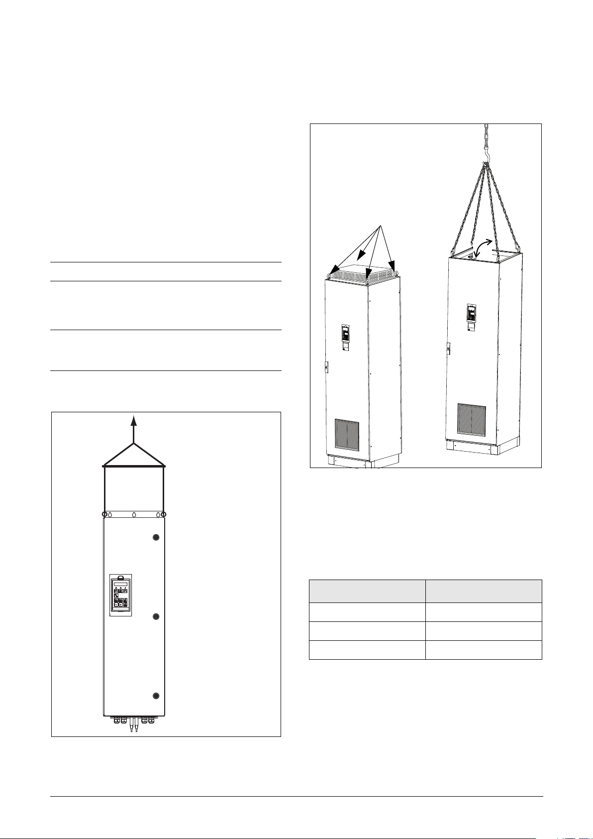
2.1 Lifting instructions
Note: To prevent personal risks and any damage to
the unit during lifting, it is advised that the lifting
methods described below are used.
Recommended for AC drive models
220 KW to 1K8 KW
Recommended for AC drive models
45 KW to 200 KW
Fig. 3 Remove the roof unit and use the lifting eyes to lift
single unit 600 mm (23.6 in) and 900 mm (35.4 in).
Single cabinet drives can be lifted/transported safely using
the eye bolts supplied and lifting cables/chains as in
illustration Fig. 3 above.
Depending on the cable/chain angle A (in Fig. 3),
following loads are permitted:
Cable/chain angle A Permitted load
45 ° 4 800 N (1080 lbf)
60 ° 6 400 N (1439 lbf)
90 ° 13 600N (3057 lbf)
Regarding lifting instructions for other cabinet sizes, please
contact Omron.
Fig. 2 Lifting AC drive model 45 KW to 200 KW.
Omron, I126E-EN-04 Mounting 13
Page 18
2.2 Stand-alone units
The AC drive must be mounted in a vertical position against
a flat surface. Use the template (in the File archive on our
homepage) to mark out the position of the fixing holes.
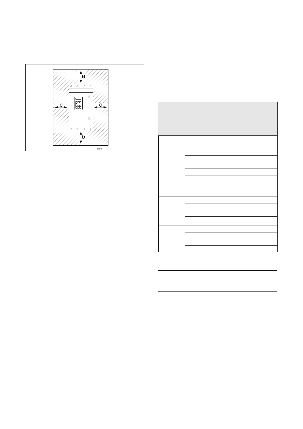
2.2.1 Cooling
Fig. 4 shows the minimum free space required around the
AC drive for the models 002 to 1K8 KW in order to
guarantee adequate cooling. Because the fans blow the air
from the bottom to the top it is advisable not to position an
air inlet immediately above an air outlet.
The following minimum separation between two AC drives,
or a AC drive and a non-dissipating wall must be
maintained. Valid if free space on opposite side.
Table 5 Mounting and cooling
Fig. 4 AC drive mounting model 1P5 KW to 1K8 KW
2x2xSX-F,
side-by-side
mm (in)
3 or more
SX-F units
B/C/D/C2/
D2 side-byside
mm (in)
3 or more
SX-F units
E/F/E2/F2
side-by-side
mm (in)
SX-F-wall,
wall-one
side
mm (in)
Frame size
B - FA,
C2-FA2,
C69-F69,
C2(69)-D2(69)
[mm(in)]
a 200 (7.9) 200 (7.9) 100 (3.9)
b 200 (7.9) 200 (7.9) 0
c 0 50 (1.97) 0
d 0 50 (1.97) 0
a 200 (7.9) 200 (7.9) 100 (3.9)
b 200 (7.9) 200 (7.9) 0
c 50 (1.97) 50 (1.97) 0
d 50 (1.97) 50 (1.97) 0
a 200 (7.9) 200 (7.9) 100 (3.9)
b 200 (7.9) 200 (7.9) 0
c 100 (3.9 50 (1.97) 0
d 100 (3.9) 50 (1.97) 0
a 100 (3.9) 100 (3.9) 100 (3.9)
b 100 (3.9) 100 (3.9) 0
c 0 50 (1.97) 0
d 0 50 (1.97) 0
Frame size
C2, D2, E2, F2
with IP21
top cover
option
[mm(in)]
220 KW-
1K8 KW
cabinet
[mm(in)]
NOTE: When a 220 KW to 1K8 KW model is placed
between two walls, a minimum distance at each side
of 200 mm (7.9 in) must be maintained.
14 Mounting Omron, I126E-EN-04
Page 19
2.2.2 Mounting schemes
12.5 kg
(26.5 lb)
C
D
F
G
ø13 mm(x2)
(0.51 in)
ø7 mm(x4)
(0.27 in)
E
B
A
Glands
M20
Glands
M32
Gland
M16
Gland
M25
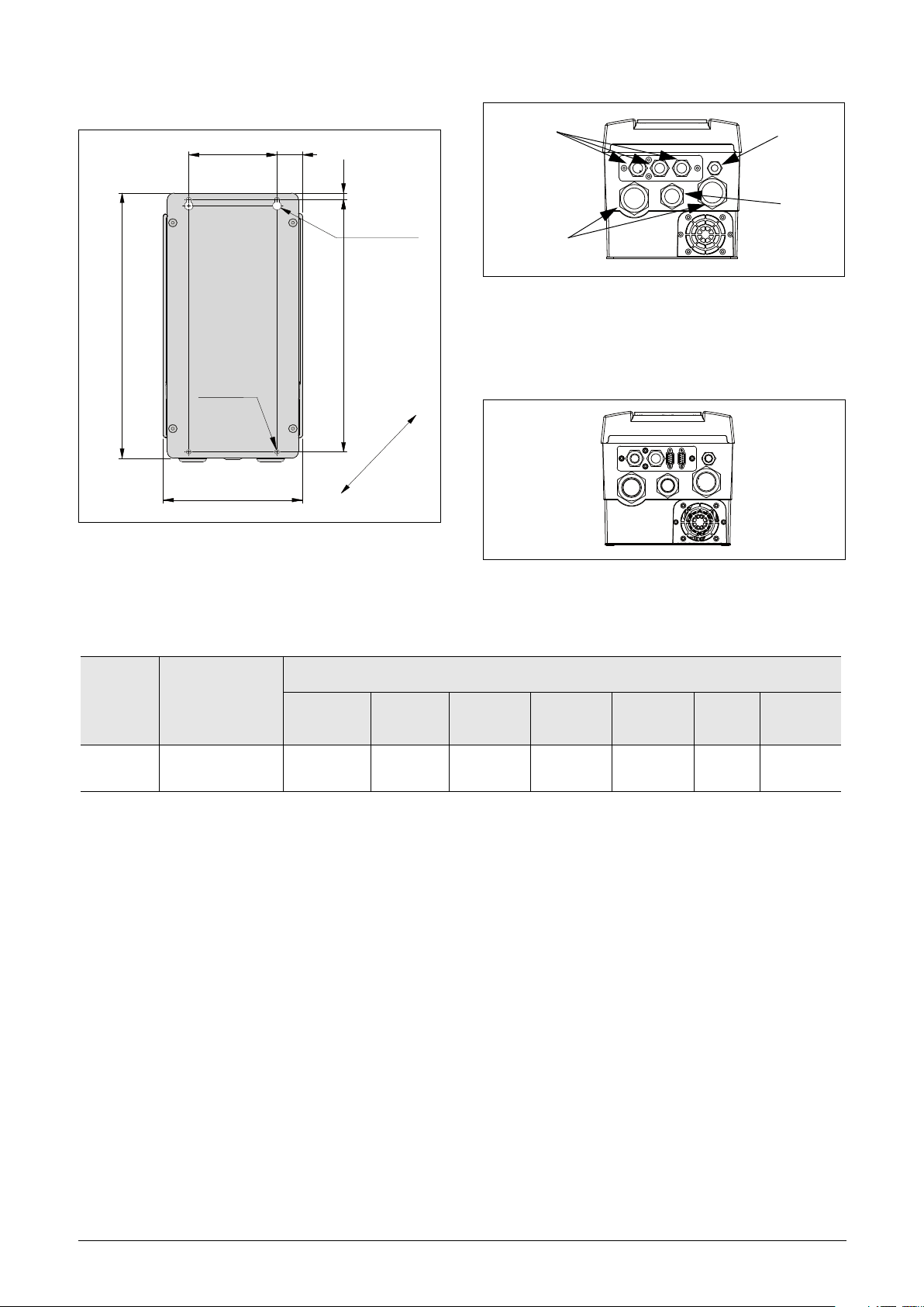
Fig. 5 Omron SX-F Model SX-D40P7 to D47P5
(Frame size B).
Table 6 Dimensions connected to Fig. 5.
Frame
size
Omron SX-F
model
A B C D E F
Fig. 6 Cable interface for mains, motor and communication,
Omron SX-F Model SX-D0P7 to D7P5
(Frame size B).
Fig. 7 Omron SX-F Model SX-D40P7 to D47P5 (Frame
size B) example with optional CRIO interface and
D-sub connectors.
Dimensions in mm (in)
G
(depth)
B D40P7 - D47P5
416
(16.4)
396
(15.6)
128.5
(5.04)
37
(1.46)
10
(0.39)
202.6
(7.98)
203
(7.99)
Omron, I126E-EN-04 Mounting 15
Page 20
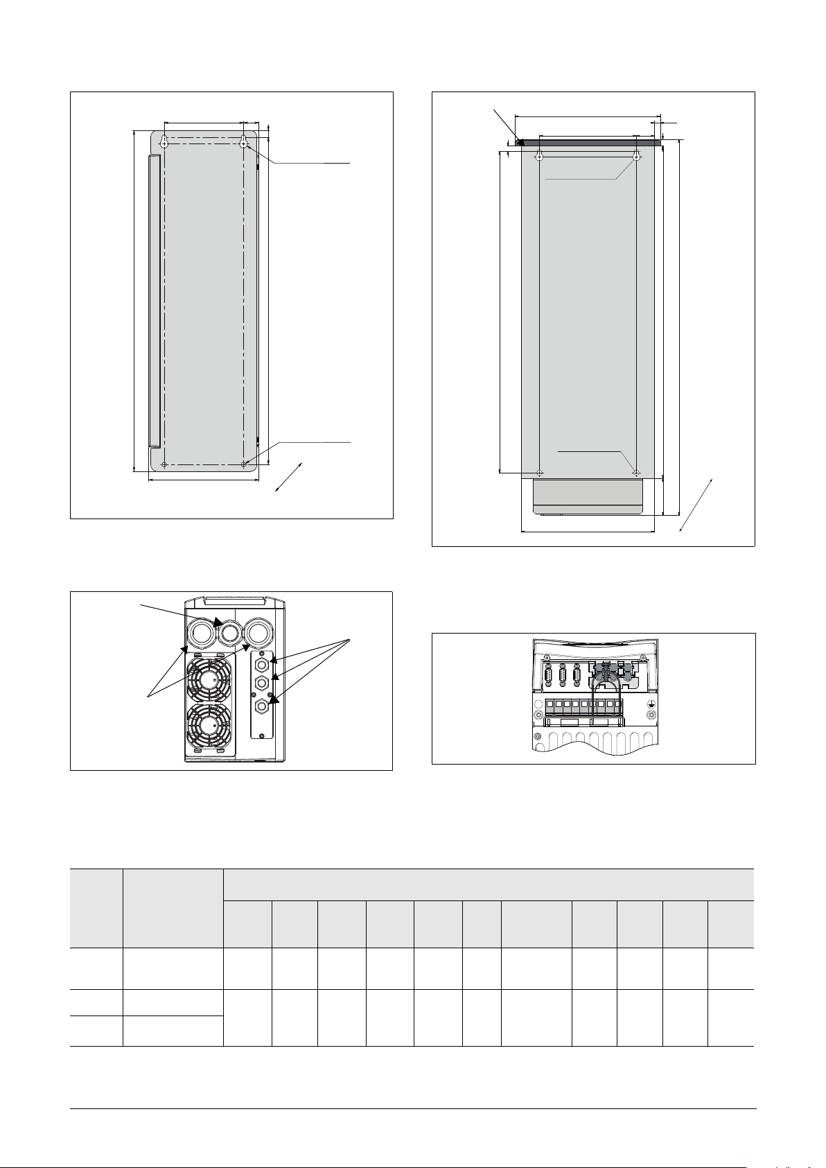
Fig. 8 Omron SX-F Model SX-D4011 to D4022 (Frame
24 kg
(53 lb)
C
D
F
G
ø13 mm(x2)
E
B
A
ø7 mm(x4)
(0.27 in)
(0.51 in)
Gland
M25 (026-031)
Glands
M20
Glands
M32 (026-031)
M32 (037-046)
M40 (037-046)
IP21 top cover (optional)
ø7mm (x4)
(0.27 in)
ø13 mm(x2)
(0.51 in)
G
A
K
F
17 kg
(38 lb)
B
H
I
C
J
E
D
size C).
Fig. 9 Cable interface for mains, motor and communication,
Omron SX-F Model SX-D4011 to D4022 (Frame
size C).
Table 7 Dimensions connected to Fig. 8 and Fig. 10.
Fig. 10 Omron SX-F Model SX-A4011 to A4030 (Frame size
C2), Model SX-A61P5 to A6022 (Frame size
C2(69)), backside view.
PE
L1 L2 L3 DC- DC+ R U V W
Fig. 11 Bottom view Omron SX-F Model SX-A4011 to
A4030 (Frame size C2) Model SX-A61P5 to A6022
(Frame size C2(69)), with cable interface for mains,
motor, DC+/DC-, brake resistor and control.
Dimensions in mm (in)
(depth)
10
(0.39)
178
(7)
167
(7)
292
(11.5)
267 (10.5)
IP21 282
(11.1)
G
H I J K
----
196
(7.7)
10
(0.39)
23.5
(0.9)
Frame
size
C D4011 - D4022
C2 A4011 - A4030
C2(69) A61P5 - A6022
Omron
SX-F
model
A B C D E F
512
(20.2)
585.5
(23)
492
(19.4)
471
(18.5)
128.5
(5.04)
128.5
(5.04)
24.8
(0.95)
23.8
(0.91)13(0.51)
16 Mounting Omron, I126E-EN-04
496
(19.5)
Page 21
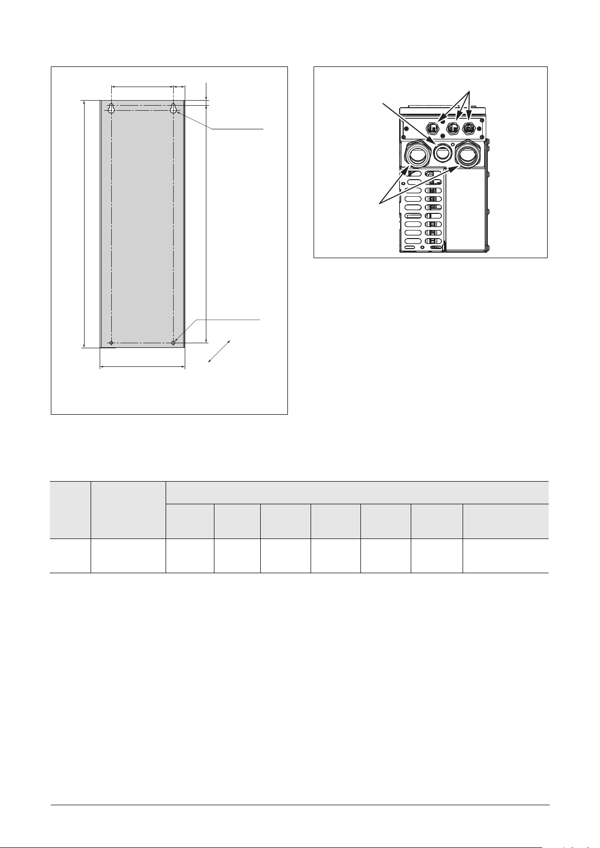
C
A
17 kg
(37.4 lb)
(0.27 in)
ø13 mm(x2)
(0.51 in)
ø7mm (x4)
Glands
Gland
M25
Glands
M20
M32
D
E
B
Fig. 13 Cable interface for mains, motor and communication,
Omron SX-F Model SX-A61P5 to A6022 (Frame size
C69).
F
G
Fig. 12 Omron SX-F Model SX-A61P5 to A6022 (Frame size
C69).
Table 8 Dimensions connected to Fig. 12.
Frame
size
C69 A61P5 - A6022
Omron SX-F
model
A B C D E F
512
(20.2)
492
(19.4)
128.5
(5.06)
Dimensions in mm (in)
24.8
(0.98)
10
(0.39)
178
(7.01)
G
(depth)
314 (12.36)
Excl. PPU G
291.5 (11.5)
Omron, I126E-EN-04 Mounting 17
Page 22
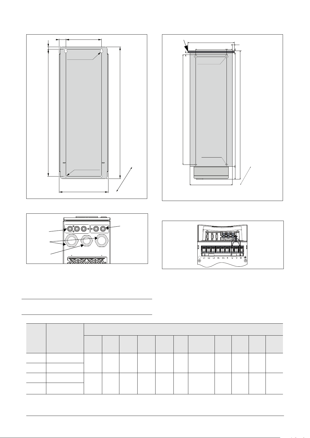
Fig. 14 Omron SX-F Model SX-D4030 to D4037(Frame size
32 kg
(71 lb) F
G
B
A
ø7 mm(x4)
(0.27 in)
C
D
ø13 mm(x2)
E
(0.51 in)
Glands
M20
Glands
M20
Glands
M50
Glands
M40
IP21 top cover (optional)
30 kg
(66 lb)
ø7 mm (x4)
(0.27 in)
ø13 mm(x2)
(0.51 in)
I
C
H
E
F
G
K
A
D
B
J
D), Model SX-D6030 to D6055, (Frame size D69).
Fig. 16 Omron SX-F Model SX-A4030 to
A4055 (Frame size D2), Model SX-A6030 to A6055
(Frame size D2(69)), backside view.
PE
Fig. 15 Cable interface for mains, motor and communication,
Omron SX-F Model SX-D4030 to D4037 (Frame
size D), Model SX-D6030 to D6055 (Frame size
NOTE: Glands for size B, C, D, C69 and D69 are available
as option kit.
D69).
Table 9 Dimensions connected to Fig. 14 and Fig. 16.
Frame
size
D D4030 - D4037
D69 A6030 - A6055
D2 A4037 - A4055
D2(69) D6030 - D6055
18 Mounting Omron, I126E-EN-04
Omron SX-F
model
Fig. 17 Bottom view Omron SX-F Model SX-A4037 to
SX-A4055 (Size D2), Model SX-A6030 to A6055
(Frame size D2(69)), with cable interface for mains,
motor, DC+/DC-, brake resistor and control.
Dimensions in mm (in)
A B C D E F
570
(22.4)
570
(22.4)
590
(23.2)
669.
5
(26.3)
160
(6.3)
160
(6.3)
30
(0.9)
10
(0.39)
30
(0.9)13(0.51)
220
(8.7)
220
(8.7)
G
(depth)
295
(11.6)
291 (11.5)
IP21 - 307
(12.1)
H I J K
----
240
(9.5)
10
(0.39)
12.5
(0.47)
590
(23.2)
Page 23
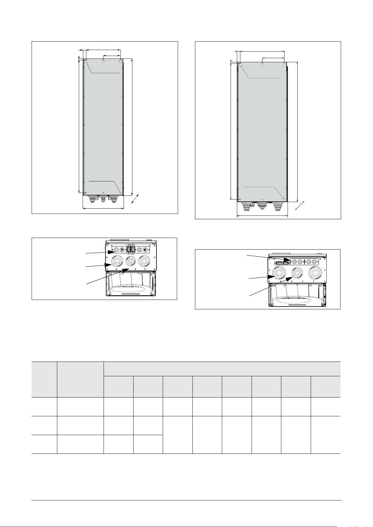
Fig. 18 Omron SX-F Model SX-D4045 to D4090 (Frame
CD
F
H
A
B
E
G
ø16 mm(x3)
(0.63 in)
ø9 mm(x6)
(0.35 in)
56/60 kg
(124/132 lb)
Cable glands M20
Cable flexible leadthrough
Ø17-42 /M50
Ø11-32 /M40
(0.67 - 1.65in)
(0.43 - 1.2 in)
Cable flexible leadthrough
C
D
F
H
A
B
E
G
ø9 mm(x6)
(0.35 in)
ø16 mm(x3)
(0.63 in)
74 kg
163 lb)
Cable glands M20
Cable flexible leadthrough
Ø23-55 /M63
Ø17-42 /M50
(0.91 - 2.1 in)
(0.67 - 1.65in)
Cable flexible leadthrough
size E).
Fig. 19 Cable interface for mains, motor, DC+/DC-, brake
resistor and communication, Omron SX-F Model
SX-D4045 to D4090 (Frame size E).
Table 10 Dimensions IP54 connected to Fig. 18 and Fig. 20.
Frame
size
Omron SX-F
model
A B C D E F
Fig. 20 Omron SX-F Model SX- D4110 to D4160 (Frame
size F), Omron SX-F Model SX-D6075 to D6200
(Frame size F69).
Fig. 21 Cable interface for mains, motor, DC+/DC-, brake
resistor and communication, Omron SX-F Model
SX- D4110 to D4160 (Frame size F), Omron SX-F
Model SX-D6075 to D6200 (Frame size F69).
Dimension in mm (in)
G
(depth)
H
E D4045 - D4090
F D4110 to D4160
F69 D6075 to D6200
Omron, I126E-EN-04 Mounting 19
925
(36.4)
925
(36.4)
1065
(41.9)
950
(37.4)
950
(37.4)
1090
(42.9)
240
(9.5)
300
(11.8)
22.5
(0.88)
22.5
(0.88)
10 (0.39)
10 (0.39)
284.5
(11.2)
344.5
(13.6)
314
(12.4)
314
(12.4)
120
150
Page 24
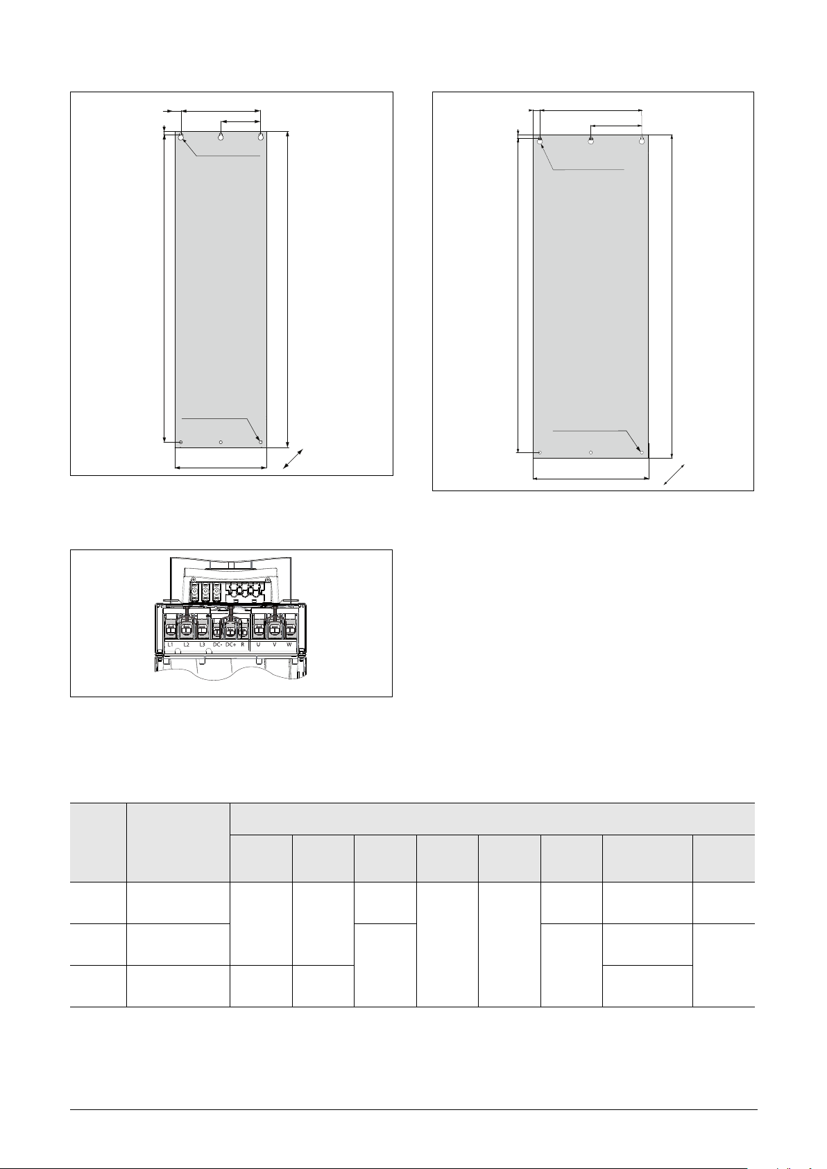
Fig. 22 Omron SX-F/ Model SX-D4075 to D4090
C
H
D
A
B
E
G
F
ø16 mm(x3)
(0.63 in)
ø9 mm(x6)
(0.35 in)
53 kg
(117 lb)
D
E
ø16 mm(x3)
(0.63 in)
ø9 mm(x6)
(0.35 in)
A
B
C
H
F
G
F2
68 kg
(150 lb)
FA2
84 kg
(185 lb)
(Frame size E2).
Fig. 23 Bottom view Omron SX-F/ Model SX-A4075 to
A4160 (Frame size E2 and F2), with cable interface
for mains, motor, DC+/DC-, brake resistor and control. (principle drawing).
Fig. 24 Omron SX-F/ Model SX-A4110 to A4160
(Frame size F2) and SX-A4200 (Frame size FA2).
Table 11 Dimensions IP20 connected to Fig. 22 and Fig. 24.
Frame
size
E2 A4075 - A4090
F2 A4110 - A4160
FA2 A4200
20 Mounting Omron, I126E-EN-04
Omron SX-F
model
Dimension in mm (in)
A B C D E F
240
925
(36.4)
1065
(41.9)
950
(37.4)
1090
(42.9)
(9.5)
300
(11.8)
22.5
(0.88)
10
(0.39)
275
(10.8)
335
(13.2)
G
(depth)
294 (11.6)
IP21 - 323 (12.7)
294 (11.6)
IP21 - 323 (12.7)
306 (12)
IP21 - 323 (12.7)
H
120
(4.7)
150
(5.9)
Page 25
D
ø16 mm(x3)
(0.63 in)
ø9 mm(x6)
(0.35 in)
95 kg
(209 lb)
Cable glands M20
(x5)
(0.91 - 2.1 in)
Ø23-55 /M63
Cable flexible leadthrough
E
A
C
H
B
F
G
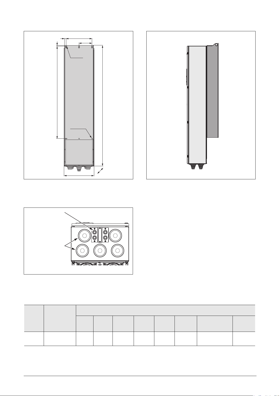
Fig. 25 Omron SX-F Model SX-D4200 Frame size FA).
Fig. 26 Cable interface for mains, motor, DC+/DC-, brake
Table 12 Dimensions IP54 connected to Fig. 25.
resistor and communication, Omron SX-F Model
SX-D4200 (Frame size FA).
Fig. 27 Side view Omron SX-F Model SX-D4200
(Frame size FA).
Frame
size
FA SX-D4200
Omron, I126E-EN-04 Mounting 21
Omron SX-F
model
Dimension in mm (in)
A B C D E F
1055
(41.5)
1395
(54.9
300
(11.8)
38
(1.5)
32
(1,26)
345
(13.6)
G
(depth)
365
(14.4)
H
157
(6.18)
Page 26
2.3 Cabinet mounting
1300 (39.4 in)
2.3.1 Cooling
If the variable speed drive is installed in a cabinet, the rate of
airflow supplied by the cooling fans must be taken into
consideration.
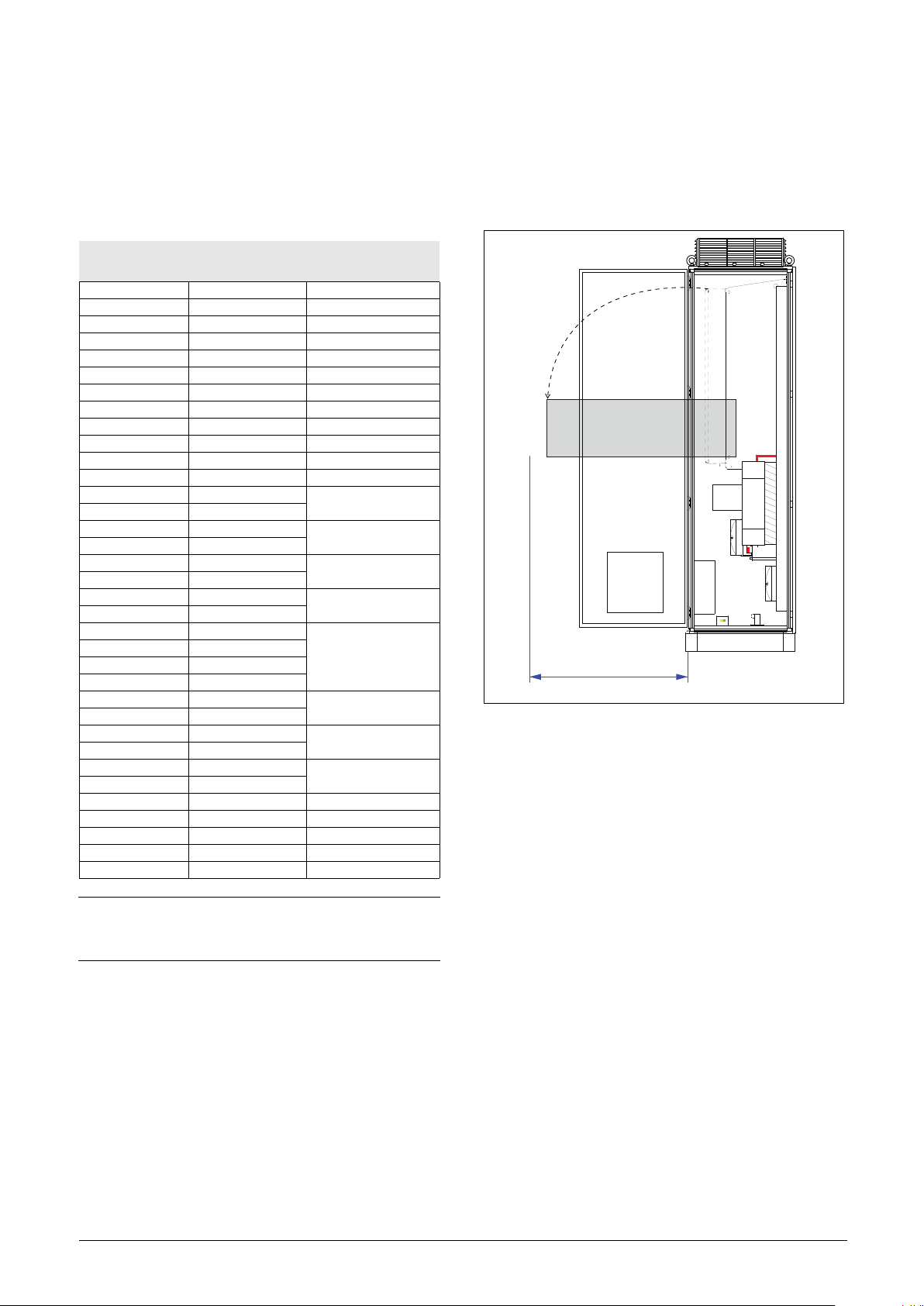
2.3.2 Recommended free space in front of cabinet
All cabinet mounted AC drives are designed in modules, so
called PEBBs. These PEBBs can be folded out to be
replaced. To be able to remove a PEBB in the future, we
recommend 1.30 meter (39.4 in) free space in front of the
cabinet, see Fig. 28.
Frame
Omron SX-F
Model
Flow rate
m3/h (ft3/min)
B D40P7 - D47P5 75 (144)
C - C2 D4011 - D4015 120 (171)
C - C2 A4018 - A4030 170 (100)
C69 D61P5 - D6022 170 (100)
C2(69) A61P5 - A6022 170 (100)
D - D2 A4022 - A4030 170 (100)
D69 D6030 - D6055 170 (100)
D2(69) D6030 - D6055 170 (100)
E - E2 D4045 - D4090 510 (300)
F - F2 D4110 - D4160 800 (471)
FA - FA2 A4200 - D4200 1020 (600)
F69 D6090 - D6200 800 (471)
H A4220 - A4250
H69 A6250 - A6400
I A4315 - A4400
I69 A6450 - A6600
J A4450 - A4500
J69 A6630 - A6800
KA A4630 - A4710
KA69 A6900 - A61K0
K A4800
K69 A61K2
L A4900
L69 A61K4
M A41K1
M69 A61K6
N A41K2
N69 A61K8
O A41K4
O69 A62K0
1600 (942)
2400 (1413)
3200 (1883)
4000 (2354)
4800 (2825)
5600 (3296)
6400 (3767)
7200 (4238)
8000 (4709)
P69 A62K2 8800 (5179)
Q69 A62K4 9600 (5650)
R69 A62K6 10400 (6121)
S69 A62K8 11200 (6592)
T69 A63K0 12000 (7063)
RITTAL
RITTAL
RITTAL
RITTAL
RITTAL
RITTAL
Fig. 28 Recommended free space in front of the cabinet
mounted AC drive.
NOTE: For the models A4450/A6630 to A63K0 the
mentioned amount of air flow should be divided
equally over the cabinets.
22 Mounting Omron, I126E-EN-04
Page 27
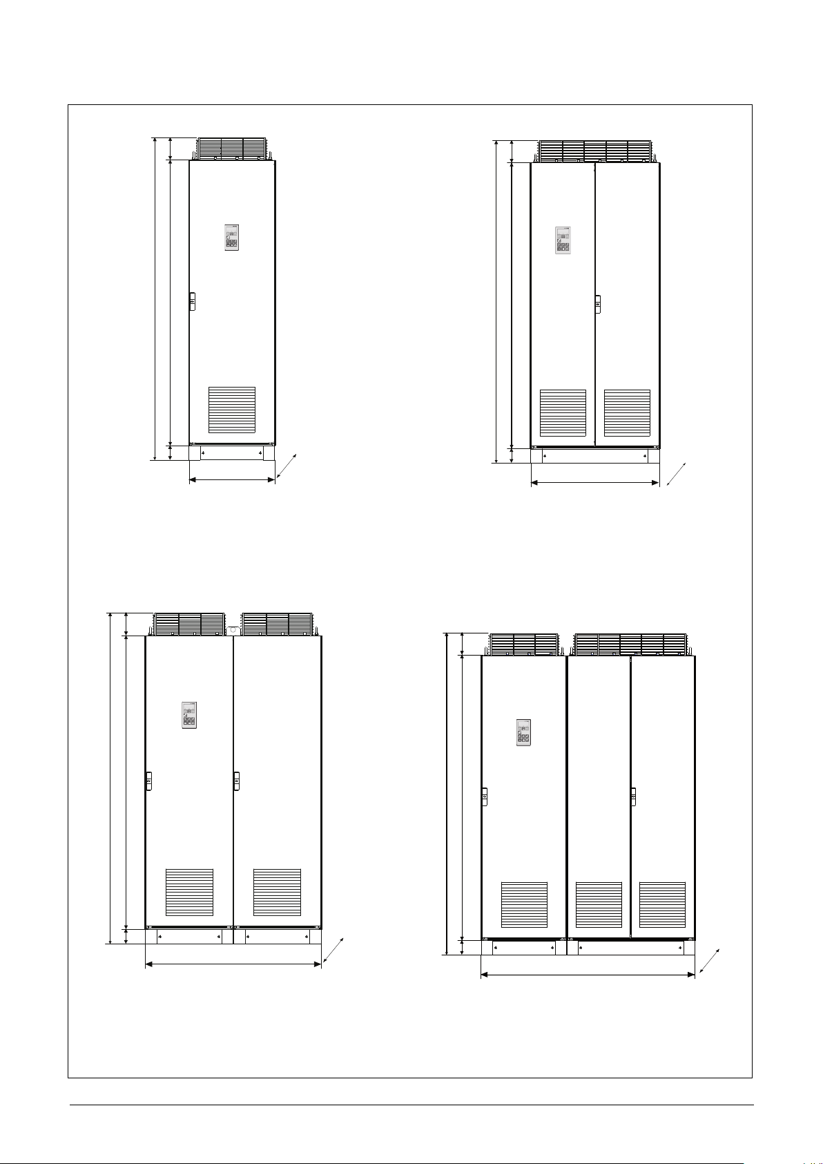
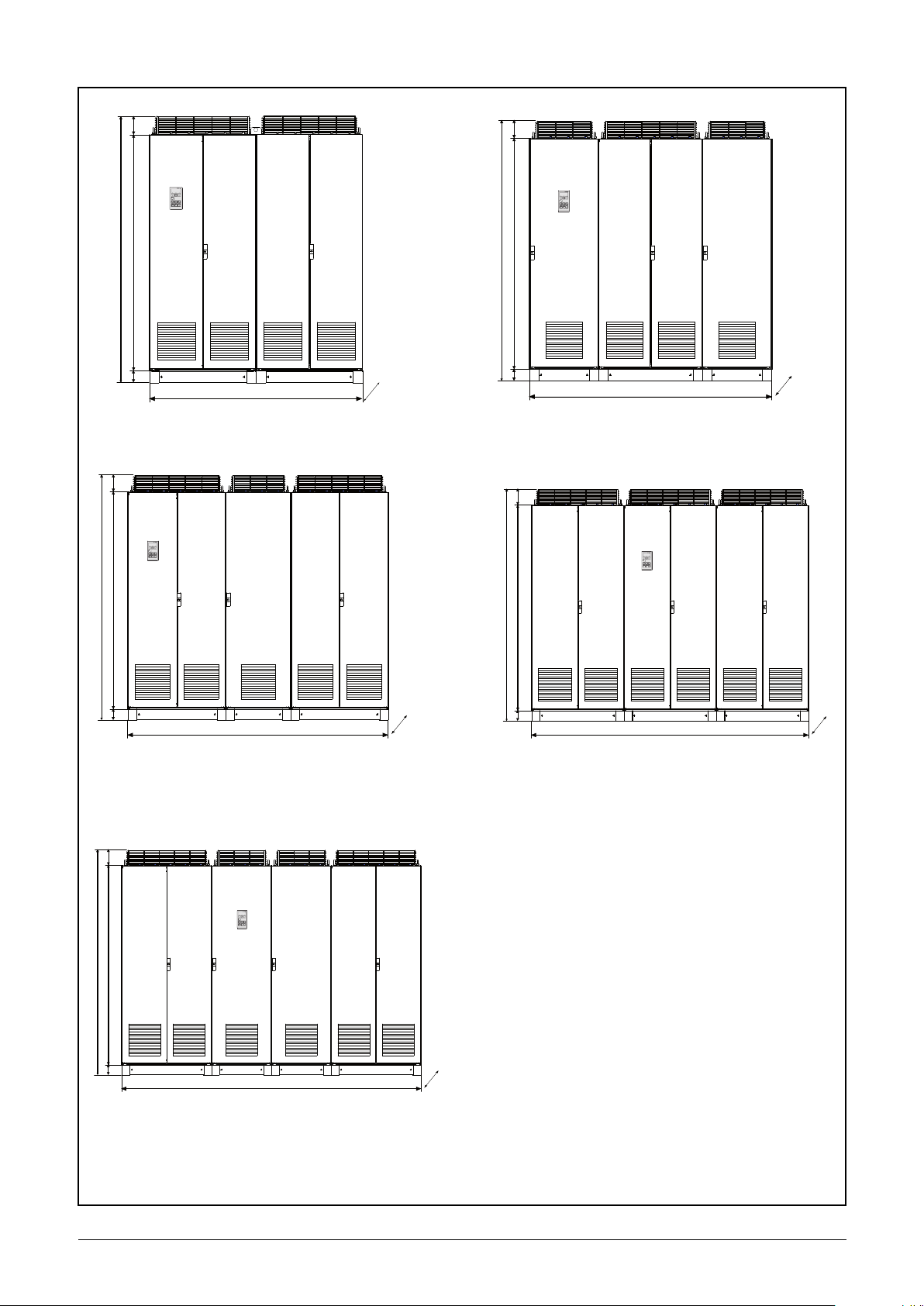
2.3.3 Mounting schemes, cabinets
2250 mm (88.6 in)
2000 mm (78.7 in)
150 mm
(5.9 in)
100 mm
(3.9 in)
600 mm (23.6 in)
600 mm
(23.6 in)
2250 mm (88.6 in)
2000 mm (78.7 in)
150 mm
(5.9 in)
100 mm
(3.9 in)
600 mm
(23.6 in)
1200 mm (47.2 in)
2000 mm (78.7 in)
2250 mm (88.6 in)
150 mm
(5.9 in)
100 mm
(3.9 in)
600 mm
(23.6 in)
900 mm (35.4 in)
2000 mm (78.7 in)
2250 mm (88.6 in)
150 mm
(5.9 in)
100 mm
(3.9 in)
600 mm
(23.6 in)
1500 mm (59.0 in)
RITTALRITTALRITTAL
Omron SX-F: Model D4220 to D4250
(Frame sizes G and H)
Omron SX-F: Model D6250 to D6400
(Frame size H69)
RITTAL
RITTALR ITTAL
RITTAL
RITTAL
Omron SX-F: Model D4315 to D4400
(Frame size I)
Omron SX-F: Model D6450 to D6600
(Frame size I69)
RITTALRITTALRITTAL
Omron SX-F: Model D4450 to D4500
(Frame size J)
Omron SX-F: Model D6630 to D6800
(Frame size J69)
RITTALRITTALRITTAL
Omron SX-F: Model D4630 to D4710
(Frame size KA)
Omron SX-F: Model D6900 to D61K0
(Frame size KA69)
Omron, I126E-EN-04 Mounting 23
Page 28
RITTAL
1800 mm (71 in)
2250 mm (88.6 in)
2000 mm (78.7 in)
150 mm
(5.9 in)
(3.9 in)
100 mm
600 mm
(23.6 in)
2400 mm (94.5 in)
150 mm
(5.9 in)
100 mm
2250 mm (88.6 in)
2000 mm (78.7 in)
(3.9 in)
600 mm
(23.6 in)
3000 mm (118.2 in)
150 mm
(5.9 in)
2250 mm (88.6 in)
2000 mm (78.7 in)
(3.9 in)
100 mm
2100 mm (82.7 in)
150 mm
(5.9 in)
2250 mm (88.6 in)
2000 mm (78.7 in)
100 mm
(3.9 in)
600 mm
(23.6 in)
2700 mm (106.3 in)
2250 mm (88.6 in)
2000 mm (78.7 in)
150 mm
(5.9 in)
(3.9 in)
100 mm
600 mm
(23.6 in)
RITTAL
RITTAL
RITTAL
RITTALRITTAL
RITTAL
RITTAL
RITTALRITTAL
Omron SX-F: Model D4800 (Frame size K)
Omron SX-F: Model D61K2 (Frame size K69)
Omron SX-F: Model D41K1 (Frame size M)
Omron SX-F: Model D61K6 (Frame size M69)
Omron SX-F: Model D4900 (Frame size L)
Omron SX-F: Model D61K4 (Frame size L69)
Omron SX-F: Model D41K2 (Frame size N)
Omron SX-F: Model D61K8 (Frame size N69)
600 mm
Omron SX-F: Model D41K4 (Frame size O)
(23.6 in)
Omron SX-F: Model D62K0 (Frame size O69)
24 Mounting Omron, I126E-EN-04
Page 29
3. Installation
A
The description of installation in this chapter complies with
the EMC standards and the Machine Directive.
Select cable type and screening according to the EMC
requirements valid for the environment where the AC drive
is installed.
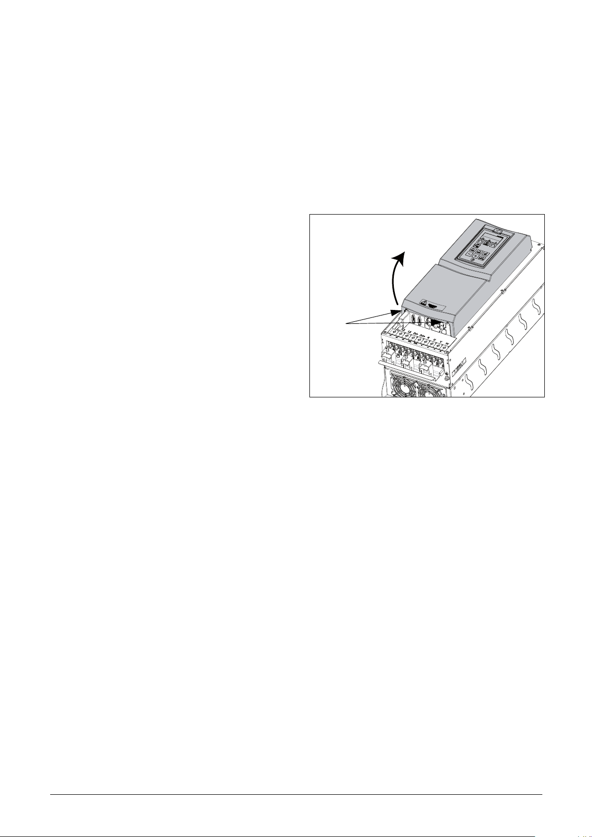
3.1.1 Remove/open front cover
Frame sizes B - FA (IP54)
Remove/open the front cover to access the cable connections
and terminals. On Frame size B and C loosen the four
screws and remove the cover. On Frame size D and up
unlock the hinged cover with the key and open it. On Frame
size FA loosen the three screws on the hinged cover and open
it.
3.1 Before installation
Read the following checklist and prepare for your
application before installation.
• Local or remote control.
• Long motor cables (>100m (> 330 ft)), refer to section
Long motor cables page 31.
• Motors in parallel, refer to menu Drive Mode [213],
page 92.
• Functions used.
• Suitable AC drive size in proportion to the
motor/application.
If the AC drive is temporarily stored before being connected,
please check the technical data for environmental
conditions. If the AC drive is moved from a cold storage
room to the room where it is to be installed, condensation
can form on it. Allow the AC drive to become fully
acclimatised and wait until any visible condensation has
evaporated before connecting the mains voltage.
Frame size C2 - F2 and FA2 (IP20/21)
Fig. 29 Remove the front cover on frame size C2 - F2 and FA2
(principle drawing).
To be able to access all cable connections and terminals, first
open and remove the front cover in following order.
• Loosen the two screws A (see Fig. 29) at the bottom of
the cover a couple of turns (you do not have to remove
the screws).
• Swing out the lower part of the cover a bit and remove
the cover downwards. Be careful, don't swing out the
cover too much as this could damage the “lips” at the
upper hinges.
Now it is easy to access all terminals.
Omron, I126E-EN-04 Installation 25
Page 30
3.1.2 Remove/open the lower front
B
cover on Frame size E2, F2
and FA2 (IP20/21)
3.2 Cable connections for
small and medium frame
sizes
IP54 - SX-D41P5 to D4037 (Frame sizes B, C and D)
IP54-SX-D61P5 to D6055 (Frame sizes C69 and D69)
IP20/21 - SX-A4011 to A4200 (Frame sizes C2, D2, E2, F2
and FA2)
IP20/21 - SX-A61P5 to A6055 (Frame sizes C2(69) and
D2(69))
3.2.1 Mains cables
Dimension the mains and motor cables according to local
regulations. The cable must be able to carry the AC drive
load current.
Recommendations for selecting
mains cables
• To fulfil EMC purposes it is not necessary to use
screened mains cables.
Fig. 30 Loosen the two screws and remove the lower cover
(principle drawing)
In order to access the mains, motor, DC+/DC- and brake
terminals, remove the lower cover in following order
• Loosen the two screws B (see Fig. 30).
• Pull down the cover a bit and lift it away.
• Use heat-resistant cables, +75 °C (167 °F) or higher.
• Dimension the cables and fuses in accordance with local
regulations and the nominal input current of the drive
See table 64, page 248.
• PE conductor cross-sectional area shall for phase cable
size < 16 mm
or a second PE conductor with same area as original PE
conductor,
for cable size above 16mm
equal to 35mm
tional area shall be at least 16mm
For cables >35mm
sectional area should be at least 50% of the used phase
conductor.
When the PE conductor in the used cable type is not in
accordance with the above mentioned cross-sectional
area requirements, a separate PE conductor should be
used to establish this.
• The litz ground connection see fig. 42, is only necessary
if the mounting plate is painted. All the AC drives have
an unpainted back side and are therefore suitable for
mounting on an unpainted mounting plate.
Connect the mains cables according to fig. 31 to 39. The
AC drive has as standard a built-in RFI mains filter that
complies with category C3 which suits the Second
Environment standard.
2
(6 AWG) be >10 mm2 Cu (16 mm2 Al)
2
2
(2 AWG) the PE conductor cross-sec-
2
(6 AWG) but smaller or
2
(6 AWG).
(>2 AWG) the PE conductor cross-
26 Installation Omron, I126E-EN-04
Page 31

L1
L2
L3
DC-
DC+
R
U
V
W
EMC gland,
Screen connection
of motor cables
PE
L
1
L
2
L
3
D
C
-
D
C
+
R
U
V
W
PE
EMC gland Screen connection
of motor cables
W
L1
L2 L3
DC-
DC+ R
U
V
PE
EMC gland - s
creen connection
of motor cables
L1 L2 L3 DC- DC+ R U V W
PE
Strainrelief and EMC clamp
Strainrelief and EMC clamp
for brake resistor
cables (option)
M
o
t
o
r
M
a
i
n
s
for screen connection
of cables
DC-
DC+
R
U
V
W
PE
L3
L2
L1
PE
EMC gland - screen connection
of motor cables
Fig. 31 Mains and motor connections, model D41P5 to
D47P5, frame size B.
Fig. 32 Mains and motor connections, model D4011 to
D4022, frame size C.
Fig. 34 Mains and motor connections model A4011 to
A4030, frame size C2 and model A61P5 to A6022
frame size C2(69).
Fig. 33 Mains and motor connections, model D61P5 to
Omron, I126E-EN-04 Installation 27
D6022, frame size C69.
Fig. 35 Mains and motor connection, model D4030 to
D4037, frame size D and model D6030 to D6055
frame size D69.
Page 32

L1 L2 L3 DC- DC+ R U V W
PE
M
a
i
n
s
M
o
t
o
r
for brake resistor
cables (option)
Strainrelief and EMC clamp
also for screen connection
of cables
Strainrelief and EMC clamp
PE
M
o
t
o
r
M
a
i
n
s
Strainrelief and EMC clamp
also for screen connection
of cables
PE
DC+
DC-
R
PE
M
o
t
o
r
M
a
i
n
s
Strainrelief and EMC clamp
also for screen connection
of cables
DC- DC+ R
PE
M
o
t
o
r
M
a
i
n
s
Strainrelief and EMC clamp
also for screen connection
of cables
M
a
i
n
s
M
o
t
o
r
M
o
t
o
r
Fig. 36 Mains and motor connections model A4037 to
A4055, frame size D2 and model A6030 to A6055
frame size D2(69).
Fig. 38 Mains and motor connections model D4075 to
D4160 (frame sizes E2 and F2) with the optional terminals for DC-, DC+ and Brake (principle drawing)
Fig. 37 Mains and motor connections model D4075 to
28 Installation Omron, I126E-EN-04
D4160 (frame sizes E2 and F2) (principle drawing).
Fig. 39 Mains and motor connections model A4200-E3
(frame size FA2) with the optional terminals for DC-,
DC+ and Brake (principle drawing)
Page 33

Table 13 Mains and motor connections
L1,L2,L3
PE
U, V, W
DC-,DC+,R
Mains supply, 3 -phase
Safety earth (protected earth)
Motor earth
Motor output, 3-phase
Brake resistor, DC-link
connections (optional)
Fig. 40 Wiring example showing Protective earth, Motor earth
and Brake Resistor connection
NOTE: The Brake and DC-link Terminals are only
fitted if the DC+/DC- option or Brake Chopper Option
is built-in.
WARNING!
The Brake Resistor must be connected
between terminals DC+ and R.
WARNING!
In order to work safely, the mains earth
must be connected to PE and the motor
earth to .
3.2.2 Motor cables
To comply with the EMC emission standards the AC drive
is provided with a RFI mains filter. The motor cables must
also be screened and connected on both sides. In this way a
so-called “Faraday cage” is created around the AC drive,
motor cables and motor. The RFI currents are now fed back
to their source (the IGBTs) so the system stays within the
emission levels.
Recommendations for selecting motor
cables
• Use screened cables according to specification in table
14. Use symmetrical shielded cable; three phase conductors and a concentric or otherwise symmetrically constructed PE conductor, and a shield.
• PE conductor cross-sectional area shall for phase cable
size < 16 mm
or use a second PE conductor with same area as original
PE conductor.
For cable size above 16mm
equal to 35mm
tional area shall be at least 16mm
For cables >35mm
sectional area should be at least 50% of the used phase
conductor.
When the PE conductor in the used cable type is not in
accordance with the above mentioned cross-sectional
area requirements, a separate PE conductor should be
used to establish this.
• Use heat-resistant cables, +75 °C (167 °F) or higher.
• Dimension the cables in accordance with the rated current of the motor.
• Keep the motor cable between AC drive and motor as
short as possible.
• The screening must be connected with a large contact
surface of preferable 360
the motor housing and the AC drive housing. When
painted mounting plates are used, do not be afraid to
scrape away the paint to obtain as large contact surface as
possible at all mounting points for items such as saddles
and the bare cable screening. Relying just on the
connection made by the screw thread is not sufficient.
2
(6 AWG) be >10 mm2 Cu (16 mm2 Al)
2
2
(2 AWG) the PE conductor cross-sec-
2
(2 AWG) the PE conductor cross-
(6 AWG) but smaller or
2
(6 AWG).
° and always at both ends, to
NOTE: It is important that the motor housing has the
same earth potential as the other parts of the
machine.
• The litz ground connection, see fig. 42, is only necessary
if the mounting plate is painted. All the AC drives have
an unpainted back side and are therefore suitable for
mounting on an unpainted mounting plate.
Connect the motor cables according to U - U, V - V and
W - W, see Fig. 31, to Fig. 39.
NOTE: The terminals DC-, DC+ and R are options.
Omron, I126E-EN-04 Installation 29
Page 34

Switches between the motor and the
Screen connection
of signal cables
PE
Motor cable
shield connection
AC drive built into cabinet
AC drive
RFI-Filter
Mains
Metal EMC cable glands
Output coil (option)
Screened cables
Unpainted mounting plate
Metal connector housing
Motor
Metal EMC
coupling nut
Brake resistor
(option)
Mains
(L1,L2,L3,PE)
Litz
Motor
AC drive
If the motor cables are to be interrupted by maintenance
switches, output coils, etc., it is necessary that the screening
is continued by using metal housing, metal mounting plates,
etc. as shown in the Fig. 42.
Pay special attention to the following points:
• If paint must be removed, steps must be taken to prevent
subsequent corrosion. Repaint after making connections!
• The fastening of the whole AC drive housing must be
electrically connected with the mounting plate over an
area which is as large as possible. For this purpose the
removal of paint is necessary. An alternative method is to
connect the AC drive housing to the mounting plate
with as short a length of litz wire as possible.
• Try to avoid interruptions in the screening wherever
possible.
• If the AC drive is mounted in a standard cabinet, the
internal wiring must comply with the EMC standard.
Fig. 42 shows an example of a AC drive built into a
cabinet.
Fig. 41 Screen connection of cables.
Fig. 42 AC drive in a cabinet on a mounting plate
30 Installation Omron, I126E-EN-04
Page 35

Fig. 43 shows an example when there is no metal mounting
AC drive
RFI-Filter
Mains
Metal EMC cable
glands
Screened cables
Metal housing
Brake
resistor
(option)
Output
coils
(option)
Metal connector housing
Motor
Metal cable gland
Mains
plate used (e.g. if IP54 AC drives are used). It is important
to keep the “circuit” closed, by using metal housing and
cable glands.
cause tripping at overcurrent. Using output coils can prevent
this. Contact the supplier for appropriate coils.
Switching in motor cables
Switching in the motor connections is not advisable. In the
event that it cannot be avoided (e.g. emergency or
maintenance switches) only switch if the current is zero. If
this is not done, the AC drive can trip as a result of current
peaks.
Fig. 43 AC drive as stand alone
Connect motor cables
1. Remove the cable interface plate from the AC drive
housing.
2. Put the cables through the glands.
3. Strip the cable according to Table 15.
4. Connect the stripped cables to the respective motor
terminal.
5. Put the cable interface plate in place and secure
with the fixing screws.
6. Tighten the EMC gland with good electrical contact to the motor and brake chopper cable screens.
Placing of motor cables
• Separate the power cables (AC drive, soft starter, output
coils, filters, magnetic switches, etc.) from the signal
cables (relay control circuit, PLC, sensors,
control PCBs, electronics, etc.).
• Keep the control cables as far from the power cables as
possible.
• If power cables and control cables must be laid close to
each other, try to ensure that they do not run parallel, at
least for a distance of no more than 300 mm (12 in).
If necessary, use a cable tray with a division or stack the
cable trays.
• Ensure that where power cables and control cables cross,
they do so at 90° to each other.
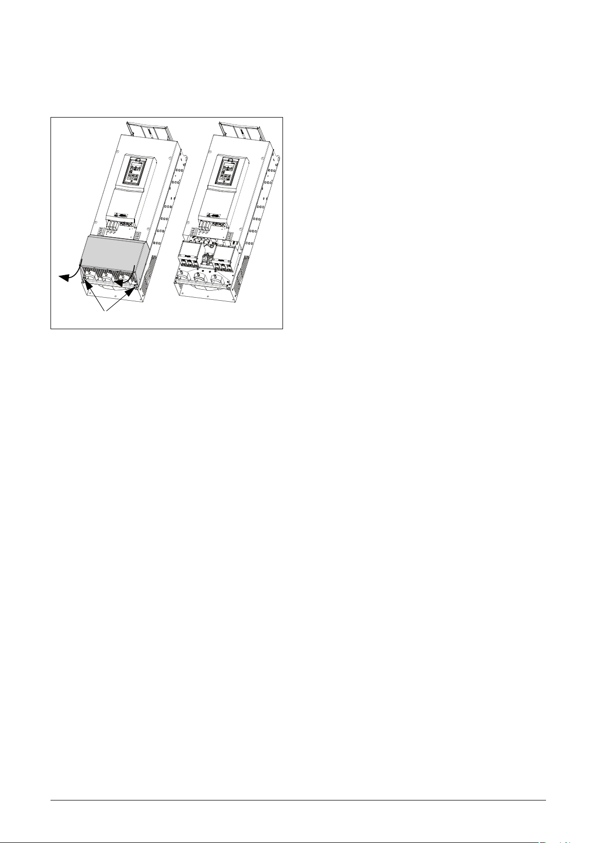
Long motor cables
If the connection to the motor is longer than 100 m
(330 ft)(for powers below 7.5 kW (10.2 hp)) please contact
Omron), it is possible that capacitive current peaks will
Omron, I126E-EN-04 Installation 31
Page 36

3.3 Connection of motor and
Cable interface
Clamps for screening
Mains cable
DC+, DC-, R (optional)
Motor cable
Mains 1
Motor 1
Cable interface
Clamp for screening
Mains cable
DC+, DC-, R (optional)
Motor cable
Mains 1
Motor 1
mains cables for larger
frame sizes
IP54 - SX-F D4045 to D4160 (Frame sizes E - F) and
SX-F D4200 (Frame size FA) and
SX-F D6075 to D6200 (Frame size F69)
IP20 - SX-F D4220 and up (Frame sizes G and up) and
SX-F D6250 and up (Frame sizes H69 and up).
Omron SX-F D4045 to D4160
Omron SX-F D6075 to D6200
To simplify the connection of thick motor and mains cables
to the AC drive, the cable interface plate can be removed.
Omron SX-F D4200
To simplify the connection of thick motor and mains cables
to the AC drive, the cable interface plate can be removed.
Fig. 44 Connecting motor and mains cables.
1. Remove the cable interface plate from the AC drive
housing.
2. Put the cables through the glands.
3. Strip the cable according to Table 15.
4. Connect the stripped cables to the respective mains/
motor terminal.
5. Fix the clamps on appropriate place and tighten the
cable in the clamp with good electrical contact to
the cable screen.
6. Put the cable interface plate in place and secure
with the fixing screws.
Fig. 45 Connection of lower mains and motor cables.
Start with the lower mains and motor cables (marked
Mains 1 and Motor 1 in Fig. 46).
1. Remove the cable interface plate from the AC Drive
housing.
2. Remove the upper mounting rail by loosen the four
fastening screws.
Fig. 46 Removed upper mounting rail.
32 Installation Omron, I126E-EN-04
Page 37

3. Put the two lower cables (Mains 1 and Motor 1
Upper mounting rail
Screw
Mains 1
Motor 1
Motor 2
Mains 2
cables) through the lower glands in the cable
interface plate.
4. Strip the cables according to Table 17 and Fig. 55.
5. Connect the cable lugs to the stripped cable ends.
6. Connect the cable lugs to respective mains and
motor terminal bolts.
7. Fix the clamps on appropriate place and tighten the
cable in the clamp with good electrical contact to
the cable screen.
Mains 1
Motor 1
Omron SX-F D4045 mount extra ferrite
core
Mount the ferrite core and its isolation sheet (included in
the delivery) on the three motor phases U,V &W.
The protective earth (PE) and the screen of the cable should
be mounted outside the core see Fig. 49.
Fig. 49 Ferrite core mounted on the motor cables
Fig. 47 Upper mounting rail mounted over the lower cables.
Continue with the upper mains and motor cables (marked
Mains 2 and Motor 2 in Fig. 48).
1. Mount the upper mounting rail over the lower,
connected cables (Mains 1 and Motor 1 cables) at
same place as before, with the four screws.
2. Put the two upper cables (Mains 2 and Motor 2)
through the glands in the cable interface plate.
3. Strip the cables according to Table 17 and Fig. 55.
4. Connect the cable lugs to the stripped cable ends.
5. Connect the cable lugs to respective mains/motor
terminal bolts.
6. Fix the clamps on appropriate place and tighten the
cable in the clamp with good electrical contact to
the cable screen.
7. Put the cable interface plate in place and secure
with the fixing screws.
The ferrite core is mounted on the motor cable to reduce
disturbances and to fulfil the EMC standards. Since the core
becomes very hot, the cables must be protected by a thermal
isolation sheet that is attached on the core. The longer
motor cables the hotter the core becomes.
NOTE: If the core is not mounted or mounted
incorrect, the AC drive does not fulfil the EMC
standards. If the protective isolation sheet is not
mounted, the motor cable can be damaged from the
hot core.
Fig. 48 All cables and cable clamps connected.
Omron, I126E-EN-04 Installation 33
Page 38

AC drive model D4220 and D6250
Motor connection
U
V
W
Mains Connection
L1
L2
L3
Ground / earth
connection
bus bar
Mains cables
Motor cables
U, V, W
L1, L2, L3
DC-, DC+, R
(optional)
3.3.1 Connection of mains and motor cables on IP20 modules
The Omron IP 20 modules are delivered complete with
factory mounted cables for mains and motor. The length of
the cables are app. 1100 mm (43 in). The cables are marked
L1, L2, L3 for mains connection and U, V, W for motor
connection.
NOTE: The IP20 modules are connected to PE/
Ground via the mounting screws. Make sure that
these will have good contact to the grounded
mounting plate/ cabinet wall.
For detailed information about use of the IP20 modules,
please contact Omron.
Fig. 50 Connect motor cables and mains cables to the
terminals and earth/ground to the bus bar.
PEBB 1
(Master)
PEBB 2
AC drive models D4220 and D6250 are supplied with
power clamps for mains and motors. For connection of PE
and earth there is a grounding bus bar.
For all type of wires to be connected the stripping length
should be 32 mm (1.26 in).
34 Installation Omron, I126E-EN-04
Fig. 51 IP20 module size H, with qty 2 x 3 mains cables and
qty 2 x 3 motor cables.
Page 39

PEBB 1
Mains cables
Motor cables
L1, L2, L3
U, V, W
(Master)
PEBB 2
PEBB 3
Fig. 52 IP20 module sizes I/I69 with qty 3 x 3 Mains cables
and qty 3 x 3 motor cables.
Omron, I126E-EN-04 Installation 35
Page 40

3.4 Cable specifications
(06-F45-cables only)
Motor/Brake
Mains
Table 14 Cable specifications
Cable Cable specification
3.4.1 Stripping lengths
Fig. 53 indicates the recommended stripping lengths for
motor and mains cables.
Mains
Motor
Control
Power cable suitable for fixed installation for the
voltage used.
Symmetrical three conductor cable with
concentric protection (PE) wire or a four
conductor cable with compact low-impedance
concentric shield for the voltage used.
Control cable with low-impedance shield,
screened.
Fig. 53 Stripping lengths for cables
Table 15 Stripping lengths for mains, motor, brake and earth cables for frame sizes B to F
Mains cable Motor cable Brake cable Earth cable
Model SX-F
D40P7 - D47P5 B
D4011 - D4022 C
D61P5 - D6022 C69
A61P5 - A6022 C2(69)
A4011 - A4030 C2
Frame
size
a
mm
(in)
90
(3.5)
150
(5.9)
65
(2.7)
b
mm
(in)
10
(0.4)
14
(0.2)
18
(0.7)
a
mm
(in)
90 (3.5)
150
(5.9)
65 (2.7)
b
mm
(in)
10
(0.4)
14
(0.2)
18
(0.7)
c
mm
(in)
20
(0.8)
20
(0.8)
36
(1.4)
a
mm
(in)
90 (3.5)
150
(5.9)
65 (2.7)
b
mm
(in)
10
(0.4)
14
(0.2)
18
(0.7)
c
mm
(in)
20
(0.8)
20
(0.8)
36
(1.4)
a
mm
(in)
90 (3.5) 10 (0.4)
150
(5.9)
65 (2.7) M6 screw*
b
mm (in)
14 (0.2)
D4030 - D4037 D
D6030 - D6055 D69
A6030 - A6055 D2(69)
A4037 – A4055 D2
A4045 - A4090 E
A4075 - A4090 E2
A4132 - A4160 F2
D4110 - D4160 F
D6075 - D6200 F69
110
(4.3)
92
(3.6)
173
(6.8)
178
(7)
17
(0.7)
18
(0.7)
25 (1)
32
(1.3)
* Cable lug.
** Valid when brake chopper electronics are built in
110
(4.3)
92 (3.6)
173
(6.8)
178 (7)
17
(0.7)
18
(0.7)
25 (1)
32
(1.3)
34
(1.4)
36
(1.4)
41
(1.6)
46
(1.8)
110
(4.3)
92 (3.6)
173
(6.8)
178 (7)
17
(0.7)
18
(0.7)
25 (1)
34
(1.4)
36
(1.4)
41
(1.6)
46
(1.8)
110
(4.3)
92 (3.6) M6 screw*
173
(6.8)
178 (7)
17 (0.7)
25 (1)
40 (1.6)**
32 (1.3)
40 (1.6)**
36 Installation Omron, I126E-EN-04
Page 41

Fig. 54 indicates the distance from the cable clamp to the connection bolts for decision of stripping lengths for the cables.
DC- DC+ R
C
A
B
Recommended screen length
for Motor and brake cables is approximate 35 mm (1.4 in).
Fig. 54 Distances from the cable clamp to the connection bolts size FA2.
Table 16 Distances from the cable clamp to the connection bolts for mains, motor, brake and earth cables for frame size FA2.
Mains cable Motor cable Brake cable Earth cable
Model SX-F
A4200-E3 FA2
Frame
size
B
mm
(in)
375
(14.8)
Bolt
dimension
M10 bolt*
B
mm
(in)
375
(14.8)
Bolt
dimension
M10 bolt*
C
mm
(in)
420
(16.5)
Bolt
dimension
M8 bolt*
A
mm
(in)
270
(10.6)
dimension
M8 bolt*
* Connect with cable lugs.
Bolt
Omron, I126E-EN-04 Installation 37
Page 42

Fig. 55 indicates the distance from the cable clamp to the connection bolts for decision of stripping lengths for the cables.
Recommended screen length
for Motor and brake cables is approximate 35 mm (1.4 in).
D
DC-
DC+
R
E
A
B
C
Fig. 55 Distances from the cable clamp to the connection bolts size FA.
Table 17 Distances from the cable clamp to the connection bolts for mains, motor, brake and earth cables for frame size FA.
Mains cable 1 Motor cable 1 Brake cable Earth cable
Model SX-F
D4200 FA
Model SX-F
D4200 FA
Frame
size
Frame
size
B
mm
(in)
360
(14.2)
Mains cable 2 Motor cable 2 Earth cable
D
mm
(in)
400
(15.7)
Bolt
dimension
M10 bolt*
Bolt
dimension
M10 bolt*
B
mm
(in)
360
(14.2)
D
mm
(in)
400
(15.7)
Bolt
dimension
M10 bolt*
Bolt
dimension
M10 bolt*
C
mm
(in)
400
(15.7)
E
mm
(in)
320
(12.6)
dimension
dimension
Bolt
M8 bolt*
Bolt
M8 bolt*
A
mm
(in)
270
(10.6)
Bolt
dimension
M8 bolt*
* Connect with cable lugs.
3.4.2 Fuse data
Please refer to the chapter Technical data, section 14.6, page 248.
38 Installation Omron, I126E-EN-04
Page 43

3.4.3 Cable connection data for mains, motor and PE cables according to IEC ratings
NOTE: The dimensions of the power terminals used in the cabinet drive models 220 KW to 3K0 can differ depending
on customer specification.
Table 18 Cable connector range and tightening torque for Omron SX-F_4, according to IEC ratings.
Cable cross section connector range
Model SX-F
D40P7
D41P5
D42P2
D43P0
D44P0
D45P5
D47P5
A4011
A4015
A4018
A4022
A4030
D4011
D4015
D4018
D4022
A4037
Frame
size
Mains and motor Brake PE
Cable area
2
mm
Tightening
torque
Nm
Cable area
2
mm
Tightening
torque
Nm
Cable area
2
mm
Tightening
B 0.5 - 10 1.2-1.4 0.5 - 10 1.2-1.4 1.5 - 16 2.6
C2 4 - 25 2 4 - 25 2 4 - 25 * 4.3
C
2.5-16
stranded
2.5-25 solid
1.2-1.4
2.5-16
stranded
2.5-25 solid
1.2-1.4
6-16
stranded
6-25 solid
1.2-1.4
0.75 -50 3.3 0.75 -50 3.3
torque
Nm
Cable
type
Copper
(Cu) /
Aluminum
(Al) 75°C
D2
10 - 70* 4.3A4045
16 - 50 7.9 16 - 50 7.9
A4055
D4030
D
D4037
A4075
E2
A4090
D4045
D4055
E
D4075
D4090
6-35
stranded
6-50 solid
16- 150
2.8-3
31 (for
16-34 mm
42 (for
35-150 mm
2
)
2
)
6-35
stranded
6-50 solid
16 - 120
2.8-3
31 (for
16-34 mm
42 (for
35-120
2
)
mm
stranded
16-50 solid
2
)
16 - 185 **
16-35
16- 150
2.8-3
31 (for
16-34 mm
42 (for
35-150 mm
10 **
2
)
2
)
Omron, I126E-EN-04 Installation 39
Page 44

Table 18 Cable connector range and tightening torque for Omron SX-F_4, according to IEC ratings.
Cable cross section connector range
Model SX-F
Frame
size
Mains and motor Brake PE
Cable area
2
mm
Tightening
torque
Nm
Cable area
2
mm
A4110
A4132
F2
31 (for
25-34 mm
2
)
A4160
D4110
25 - 240
42 (for
35-152 mm
2
)
16 - 150
D4132
F
D4160
56 (for
153-240
2
)
mm
A4200-E3 FA2
D4200 FA
M10
connection
47
M8
connection
A4220
H (2x) 25 - 240
(2x) 25 - 240
A4250
A4315
I (3x) 25 - 240 (3x) 25 - 240A4355
A4400
A4450
31 (for
25-34 mm
2
)
J (4x) 25 - 240 (4x) 25 - 240
A4500
A4630
42 (for
35-152 mm
2
)
KA (5x) 25 - 240 (5x) 25 - 240
A4710
A4800 K (6x) 25 - 240 (6x) 25 - 240
56 (for
153-240
2
)
mm
A4900 L (7x) 25 - 240 (7x) 25 - 240
Tightening
torque
Nm
31 (for
16-34 mm2)
42 (for
35-150
2
)
mm
24
31 (for
25-34 mm
42 (for
35-152
2
)
mm
56 (for
153-240
2
)
mm
Cable area
2
mm
25-34 mm2)
25 - 240
35-152 mm
16 - 185 **
M8
connection
2
)
PE/Earth via mounting
screws/mounting frame.
In order to secure proper
earthing, always use all
mounting screws and
tighten them thoroughly.
Tightening
torque
Nm
31 (for
42 (for
56 (for
153-240
2
)
mm
10 **
24
2
)
Aluminum
Aluminum
Aluminum
Cable
type
Copper
(Cu) /
(Al) 75°C
Copper
(Cu) /
(Al) 75°C
Copper
(Cu) /
(Al) 75°C
A41K1 M (8x) 25 - 240 (8x) 25 - 240
A41K2 N (9x) 25 - 240 (9x) 25 - 240
A41K4 O
(10x)
25 - 240
(10x)
25 - 240
* With cable lug for M6 screw.
** Valid when brake chopper electronics are built in.
*** Use 90 °C Mains and motor cables if surrounding temperature is higher than 35 °C otherwise 75 °C cables.
**** IP 23 or IP 54 for cabinet drive.
40 Installation Omron, I126E-EN-04
Page 45

Table 19 Cable connector range and tightening torque for Omron SX-F_6, according to IEC ratings
Cable cross section connector range
Model SX-F
A/D61P5
A/D62P2
A/D63P0
A/D64P0
A/D65P5
A/D67P5
A/D6011
A/D6015
A/D6018
A/D6022
A/D6030
A/D6037
A/D6045
A/D6055
D6075
D6090
D6110
D6132
D6160
D6200
Frame
Mains and motor Brake PE
size
Cable area
mm
2.5 - 16
C69/
C2(69)
stranded
2.5 - 25
solid
D69/
D2(69)
6 - 35
stranded
10 - 50 solid
F69 16 - 150
2
Tightening
torque
Nm
1.2 - 1.4
2.8 - 3
31 (for
16 - 34 mm
42 (for
35-150 mm
Cable area
mm
2.5 - 16
stranded
2.5 - 25 solid
6 - 35
stranded
10-50 solid
2
)
16 - 120
2
)
Cable
Tightening
2
torque
Nm
Cable area
2
mm
Tightening
torque
Nm
type
6 - 16
1.2 - 1.4
stranded
1.2 - 1.4
6 - 25 solid
Copper
(Cu)/
Aluminum
(Al)
75°C
2.8 - 3
6 - 35
stranded
2.8 - 3
10 - 50 solid
31 (for
16 - 34
2
mm
42 (for
35-120
2
mm
)
)
16 - 150
16 - 185 **
31 (for
16 - 34 mm
42 (for
35-150 mm
10 **
2
)
2
)
Omron, I126E-EN-04 Installation 41
Page 46

Table 19 Cable connector range and tightening torque for Omron SX-F_6, according to IEC ratings
A6250
A6315
A6355
A6400
A6450
A6600
A6630
H69 (2x) 25 - 240
I69 (3x) 25 - 240 (3x) 25 - 240A6500
J69 (4x) 25 - 240 (4x) 25 - 240A6710
(2x) 25 - 240
A6800
A6900
KA69 (5x) 25 - 240 (5x) 25 - 240
31 (for
25-34 mm
2
)
A61K0
A61K2 K69 (6x) 25 - 240 (6x) 25 - 240
42 (for
35-152 mm
2
)
A61K4 L69 (7x) 25 - 240 (7x) 25 - 240
A61K6 M69 (8x) 25 - 240 (8x) 25 - 240
A61K8 N69 (9x) 25 - 240 (9x) 25 - 240
A62K0 O69
A62K2 P69
A62K4 Q69
A62K6 R69
A62K8 S69
A63K0 T69
(10x) 25 -
240
(11x) 25 -
240
(12x) 25 -
240
(13x) 25 -
240
(14x) 25 -
240
(15x) 25 -
240
56 (for
153-240
2
)
mm
(10x) 25 -
240
(11x) 25 -
240
(12x) 25 -
240
(13x) 25 -
240
(14x) 25 -
240
(15x) 25 -
240
31 (for
25-34 mm2)
42 (for
35-152
2
)
mm
56 (for
153-240
2
)
mm
PE/Earth via mounting
screws/mounting frame.
In order to secure proper
earthing, always use all
mounting screws and
tighten them thoroughly.
Copper
(Cu)/
Aluminum
(Al)
75°C
** Valid when brake chopper electronics are built in.
42 Installation Omron, I126E-EN-04
Page 47

3.4.4 Cable connection data for mains, motor and PE cables according to NEMA ratings
List of cable cross section connector range with minimum
required AWG cable cross section which fits to the terminals
according to UL-requirements.
Table 20 Cable connector range and tightening torque for Omron SX-F_4, according to NEMA ratings
Cable cross section connector range
Model SX-F
D40P7
D41P5
D42P2
D43P0
D44P0
D45P5
D47P5
A4011
A4015
A4018
A4022
A4030
D4011
D4015
D4018
Frame
size
Mains and motor Brake PE
Cable range
AWG
Tightening
torque
Lb-In
Cable range
AWG
Tightening
torque
Lb-In
Cable range
AWG
Tightening
torque
B 20 - 8 11.5 20 - 8 11.5 16 - 6 23
C2 12 - 4 18 12 - 4 18 12 - 4* 38
C 18 - 4 10.6-12.3 18 - 4 10.6-12.3 18 - 4 10.6-12.3
Cable
type
Lb-In
Copper
(Cu) 75°C
D4022
A4037
A4055
D4030
D4037
D4075
D4090
D4045
D4055
D4075
D4090
10 - 0 30 - 50 10 - 0 30 - 50
D2
8 - 2/0* 38A4045
3 - 2/0 70 3 - 2/0 70
D 10 - 0 24.3-26.1 10 - 0 24.3-26.1 10 - 0 24.3-26.1
E2
E
6 - 300
kcmil
275 (for
AWG 6 - 2)
375 (for
AWG 1 -
300Kcmil)
6 - 250 kcmil
275 (for
AWG 6 - 2)
375 (for
AWG 1 -
250Kcmil)
6 - 300 kcmil
6 - 2/0**
275 (for
AWG 6-2)
375 (for AWG
1-300Kcmil)
88**
Omron, I126E-EN-04 Installation 43
Page 48

Table 20 Cable connector range and tightening torque for Omron SX-F_4, according to NEMA ratings
Cable cross section connector range
Model SX-F
Frame
size
A4110
A4132
F2
A4160
D4110
F
D4132-D4160 ***
Mains and motor Brake PE
Cable range
AWG
Tightening
torque
Lb-In
Cable range
AWG
Tightening
torque
Lb-In
Cable range
AWG
275 (for
4 - 500
kcmil
AWG 4 - 2)
375 (for AWG
1 -300 kcmil)
500 (for AWG
350 -500
kcmil)
6 - 300 kcmil
275 (for
AWG 6 - 2)
375 (for
AWG
1 -
300Kcmil)
4 - 500 kcmil
6 - 2/0**
Tightening
torque
Lb-In
275 (for
AWG 4 - 2)
375 (for
AWG 1 -300
kcmil)
500 (for AWG
350 -500
kcmil)
88**
A4200-E3
D4200 FA
A4220
A4250
FA2
H
M10
connection
(2x) 4 - 500
kcmil
416
M8
connection
(2x) 4 - 500
kcmil
212
M8
connection
212
A4315
A4355
I
(3x) 4 - 500
kcmil
(3x) 4 - 500
kcmil
A4400
A4450
A4500
A4630
KA
A4710
A4800 K
A4900 L
J
(4x) 4 - 500
kcmil
(5x) 4 - 500
kcmil
(6x) 4 - 500
kcmil
(7x) 4 - 500
kcmil
275 (for
AWG 4 - 2)
375 (for
AWG 1 - 300
kcmil)
500 (for AWG
350 -500
kcmil)
(4x) 4 -500
kcmil
(5x) 4 - 500
kcmil
(6x) 4 - 500
kcmil
(7x) 4 - 500
kcmil
275 (for
AWG 4 - 2)
375 (for
AWG 1 -
300 kcmil)
500 (for
AWG 350 -
500 kcmil)
PE/Earth via mounting
screws/mounting frame.
In order to secure proper
earthing, always use all
mounting screws and
tighten them thoroughly.
Cable
type
Copper
(Cu)
75°C
Copper
(Cu)
75°C
Copper
(Cu)
75°C
A41K1 M
A41K2 N
A41K4 O
(8x) 4 - 500
kcmil
(9x) 4 - 500
kcmil
(10x) 4 - 500
kcmil
(8x) 4 - 500
kcmil
(9x) 4 - 500
kcmil
(10x)4-500
kcmil
* With cable lug for M6 screw.
** Valid when brake chopper electronics are built in.
*** Use 90
44 Installation Omron, I126E-EN-04
°C Mains and motor cables if surrounding temperature is higher than 35 °C otherwise 75 °C cables.
Page 49

3.5 Thermal protection on the motor
Standard motors are normally fitted with an internal fan.
The cooling capacity of this built-in fan is dependent on the
frequency of the motor. At low frequency, the cooling
capacity will be insufficient for nominal loads. Please
contact the motor supplier for the cooling characteristics of
the motor at lower frequency.
WARNING!
Depending on the cooling characteristics
of the motor, the application, the speed
and the load, it may be necessary to use
forced cooling on the motor.
Motor thermistors offer better thermal protection for the
motor. Depending on the type of motor thermistor fitted,
the optional PTC input may be used. The motor thermistor
gives a thermal protection independent of the speed of the
motor, thus of the speed of the motor fan. See the functions,
Motor I
2
t type [231] and Motor I2t current [232].
3.6 Motors in parallel
The Drive Mode "Speed" or "Torque", see menu [213],
performs very well in most applications based on the direct
torque control as motor control method. However in
applications with multiple motors connected in parallel to
the AC drive output one should select Drive Mode = "V/
Hz" and then it is possible to have motors in parallel as long
as the total current does not exceed the nominal value of the
AC drive. The following has to be taken into account when
setting the motor data:
Menu [221]
Motor Voltage:
Menu [222]
Motor
Frequency:
Menu [223]
Motor Power:
Menu [224]
Motor Current:
Menu [225]
Motor Speed:
Menu [227]
Motor Cos PHI:
The motors in parallel must have the
same motor voltage.
The motors in parallel must have the
same motor frequency.
Add the motor power values for the
motors in parallel.
Add the current for the motors in parallel.
Set the average speed for the motors in
parallel.
Set the average Cos PHI value for the
motors in parallel.
Omron, I126E-EN-04 Installation 45
Page 50

46 Installation Omron, I126E-EN-04
Page 51

4. Control Connections
Relay outputs
Control
signals
Switches
Option
Control
Panel
Communication
4.1 Control board
Fig. 56 shows the layout of the control board which is where
the parts most important to the user are located. Although
the control board is galvanically isolated from the mains, for
safety reasons do not make changes while the mains supply
is on!
X5
X4
C
WARNING!
Always switch off the mains voltage and
wait at least 7 minutes to allow the DC
capacitors to discharge before connecting
the control signals or changing position of any
switches. If the option External supply is used, switch
of the mains to the option. This is done to prevent
damage on the control board.
X6
321
X7
I
12
13 14 15 16 17 18 19 20 21
AO1
X1
1
U
S3 S4
I
UU
U
S2S1
II
22
AO2
DI4
DI5
DI6 DI7
DO1
DO2
DI8
23 4 567 89 10
DI2
+24VDI3
AI3AI2
AI1+10V
AI4
DI1-10V
11
41
NC
X2
R02
42 43
C
31 32
NC
R01
X8
NO
33
C
NO
X3
51
NO
52
C
R03
Fig. 56 Control board layout
Omron, I126E-EN-04 Control Connections 47
Page 52

4.2 Terminal connections
The terminal strip for connecting the control signals is
accessible after opening the front panel.
The table describes the default functions for the signals. The
inputs and outputs are programmable for other functions as
described in chapter 11. page 87. For signal specifications
refer to chapter 14. page 235.
Table 21 Control signals
Te rm i na l Name Function (Default)
Relay outputs
31 N/C 1
32 COM 1
33 N/O 1
Relay 1 output
Trip, active when the AC drive
is in a TRIP condition.
NOTE: The maximum total combined current for
outputs 11, 20 and 21 is 100mA.
NOTE: It is possible to use external 24V DC if
connection to Common (15).
Table 21 Control signals
Te rm in al Name Function (Default)
Outputs
1 +10 V +10 VDC supply voltage
6 -10 V -10 VDC supply voltage
7 Common Signal ground
11 +24 V +24 VDC supply voltage
12 Common Signal ground
15 Common Signal ground
Digital inputs
8 DigIn 1 RunL (reverse)
9 DigIn 2 RunR (forward)
10 DigIn 3 Off
16 DigIn 4 Off
17 DigIn 5 Off
18 DigIn 6 Off
19 DigIn 7 Off
41 N/C 2
42 COM 2
43 N/O 2
51 COM 3
52 N/O 3
NOTE: N/C is opened when the relay is active and N/
O is closed when the relay is active.
NOTE! Using potentiometer for reference signal to
Analogue input: Possible potentiometer value in
range of 1 kΩ to 10 kΩ (¼ Watt) linear, where we
advice to use a linear 1 kΩ / ¼ W type potentiometer
for best control linearity.
WARNING!
The relay terminals 31-52 are single
isolated. Do NOT mix SELV voltage with
e.g. 230 VAC on these terminals. A solution
when dealing with mixed SELV/system
voltage signals is to install an additional I/
O board option ( see chapter 13.8 page
229) and connect all SELV voltage signals
to the relay terminals of this option board
while connecting all 230VAC signals to the
control board relay terminals 31 - 52.
Relay 2 output
Run, active when the AC
drive is started.
Relay 3 output
Off
22 DigIn 8 RESET
Digital outputs
20 DigOut 1 Ready
21 DigOut 2 Brake
Analogue inputs
2 AnIn 1 Process Ref
3AnIn 2Off
4AnIn 3Off
5AnIn 4Off
Analogue outputs
13 AnOut 1 Min speed to max speed
14 AnOut 2 0 to max torque
48 Control Connections Omron, I126E-EN-04
Page 53

4.3 Inputs configuration
U
I
with the switches
The switches S1 to S4 are used to set the input configuration
for the 4 analogue inputs AnIn1, AnIn2, AnIn3 and AnIn4
as described in table 22. See Fig. 56 for the location of the
switches.
Table 22 Switch settings
Input Signal type Switch
AnIn1
Voltage
Current (default)
S1
S1
I
U
I
U
AnIn2
AnIn3
AnIn4
Voltage
Current (default)
Voltage
Current (default)
Voltage
Current (default)
S2
S2
S3
S3
S4
S4
I
U
I
U
I
U
I
U
I
U
NOTE: Scaling and offset of AnIn1 - AnIn4 can be
configured using the software. See menus [512],
[515], [518] and [51B] in section 11.7, page 166.
NOTE: the 2 analogue outputs AnOut 1 and AnOut 2
can be configured using the software. See menu [530]
section 11.7.3, page 174
Omron, I126E-EN-04 Control Connections 49
Page 54

4.4 Connection example
EMCfilter
+10 VDC
AnIn 1: Reference
AnIn 2
AnIn 3
AnIn 4
-10 VDC
Common
DigIn 1:RunL*
DigIn 2:RunR*
DigIn3
+24 VDC
Common
DigIn 4
DigIn 5
DigIn 6
DigIn 7
DigIn 8:Reset*
Common
AnOut 1
AnOut 2
DigOut 2
DigOut 1
Motor
Fieldbus option
or PC
Option board
Other options
0 - 10 V
4 - 20 mA
Alternative for
potentiometer
Optional
* Default setting
Relay 1
Relay 2
Relay 3
** The switch S1 is set to U
Comm. options
*** = Optional terminals X1: 78 - 79 for connection of Motor-PTC on frame sizes B, C and D.
Optional ***
Motor PTC
Possible potentiometer value in range of 1 kΩ
to 10 kΩ (¼ Watt) linear, where we advice to use a
linear 1 kΩ / ¼ W type potentiometer for best control linearity.
control**
Fig. 57 gives an overall view of a AC drive connection
example.
1
2
3
4
5
6
7
Fig. 57 Connection example
50 Control Connections Omron, I126E-EN-04
Page 55

4.5 Connecting the Control
Control signals
Term in al 78 & 79
see Table 23
Screen clamps
for signal cables
Control signals
Terminal 78 & 79
see Table 23
Screen clamps
for signal cables
motor PTC option
78 79
Feed-through of
signal cables
Screen clamps
for signal cables
See
Tab l e 23
Signals
4.5.1 Cables
The standard control signal connections are suitable for
stranded flexible wire up to 1.5 mm
wire up to 2.5 mm
NOTE: The screening of control signal cables must
comply with the immunity levels given in the EMC
Directive (reduction of noise level).
NOTE: The control cables must be separated from
motor and mains cables.
2
(AWG14) .
Table 23 Description of optional terminals in Fig. 58 to Fig. 62.
Terminals 78, 79 For connection of Motor PTC
For connection of 24V Stand-by
Terminals A-, B+
Supply (Valid for sizes D/D2/C69/
C2(69)/D69/D2(69)/FA/FA2)
2
(AWG16) and for solid
Fig. 59 Connecting the control signals, SX-F model
SX-D4011 to SX-D4022, frame size C.
Fig. 58 Connecting the control signals, SX-F model
Omron, I126E-EN-04 Control Connections 51
SX-D40P7 to SX-D47P5, frame size B.
Fig. 60 Connecting the control signals, SX-F model SX-A4011
to A4030 frame size C2 and model SX-A61P5 to
A6022 frame size C2(69).
Page 56

Fig. 61 Connecting the control signals, SX-F model
DC-
DC+
R
U
V
PE
L3
L2
L1
Control signals
Term in al 78 & 79
see Table 23
Screen clamps
for signal cables
Term in al A- & B +
see Table 23
L1 L2 L3 DC- DC+ R U V W
78 79, A- B+
Feed-through of
signal cables
Screen clamps
for signal cables
See
Tabl e 2 3
Control signals
Screen clamps
for signal cables
Screen clamps
for signal cables
Feed-through of
signal cables
Fig. 62 Connecting the control signals, SX-F model SX-A4037
SX-D4030 to D4037, frame size D and model
SX-D6030 to D6055 frame size D(69).
to A4055 frame size D2 and model SX-A6030 to
A6055 frame size D2(69).
Fig. 63 Connecting the control signals, SX-F model SX-
D4045 to D4160 and SX-F model SX-D6075 to
D6200, frame size E, F and F69 (principle drawing).
Fig. 64 Connecting the control signals, SX-F model SX-A4075
to A4200-E3 frame size E2, F2 and FA2 (principle
drawing)
52 Control Connections Omron, I126E-EN-04
Page 57

NOTE: The screening of control signal cables is
necessary to comply with the immunity levels given in
the EMC Directive (it reduces the noise level).
NOTE: Control cables must be separated from motor
and mains cables.
4.5.2 Types of control signals
Always make a distinction between the different types of
signals. Because the different types of signals can adversely
affect each other, use a separate cable for each type. This is
often more practical because, for example, the cable from a
pressure sensor may be connected directly to the AC drive.
We can distinguish between the following types of control
signals:
Analogue inputs
Voltage or current signals, (0-10 V, 0/4-20 mA) normally
used as control signals for speed, torque and PID feedback
signals.
Analogue outputs
Voltage or current signals, (0-10 V, 0/4-20 mA) which
change slowly or only occasionally in value. In general, these
are control or measurement signals.
from, for example, a pressure sensor. Therefore it is advised
to separate wiring and screening to reduce disturbances.
4.5.3 Screening
For all signal cables the best results are obtained if the
screening is connected to both ends: the AC drive side and
at the source (e.g. PLC, or computer). See Fig. 65.
It is strongly recommended that the signal cables be allowed
to cross mains and motor cables at a 90° angle. Do not let
the signal cable go in parallel with the mains and motor
cable.
4.5.4 Single-ended or double-ended connection?
In principle, the same measures applied to motor cables
must be applied to all control signal cables, in accordance
with the EMC-Directives.
For all signal cables as mentioned in section 4.5.2 the best
results are obtained if the screening is connected to both
ends. See Fig. 65.
NOTE: Each installation must be examined carefully
before applying the proper EMC measurements.
Digital
Voltage or current signals (0-10 V, 0-24 V, 0/4-20 mA)
which can have only two values (high or low) and only
occasionally change in value.
Data
Usually voltage signals (0-5 V, 0-10 V) which change rapidly
and at a high frequency, generally data signals such as
RS232, RS485, Profibus, etc.
Relay
Relay contacts (0-250 VAC) can switch highly inductive
loads (auxiliary relay, lamp, valve, brake, etc.).
Signal
type
Analogue
Digital Screened
Data Screened
Relay Not screened
Maximum wire size
Rigid cable:
0.14-2.5 mm
(AWG 26 - 14)
Flexible cable:
0.14-1.5 mm
(AWG 26 - 16)
Cable with ferrule:
0.25-1.5 mm
(AWG 24 - 16)
2
2
2
Tightenin
g torque
0.5 Nm
(4.4 LBin)
Cable type
Screened
Example:
The relay output from a AC drive which controls an
auxiliary relay can, at the moment of switching, form a
source of interference (emission) for a measurement signal
Omron, I126E-EN-04 Control Connections 53
Page 58

4.6 Connecting options
Control board
Pressure
sensor
(example)
External control
(e.g. in metal housing)
Control consol
The option cards are connected by the optional connectors
X4 or X5 on the control board see Fig. 56, page 47 and
mounted above the control board. The inputs and outputs
of the option cards are connected in the same way as other
control signals.
Fig. 65 Electro Magnetic (EM) screening of control signal
cables.
4.5.5 Current signals ((0)4-20 mA)
A current signal like (0)4-20 mA is less sensitive to
disturbances than a 0-10 V signal, because it is connected to
an input which has a lower impedance (250 Ω) than a
voltage signal (20 kΩ). It is therefore strongly advised to use
current control signals if the cables are longer than a few
metres.
4.5.6 Twisted cables
Analogue and digital signals are less sensitive to interference
if the cables carrying them are “twisted”. This is certainly to
be recommended if screening cannot be used. By twisting
the wires the exposed areas are minimised. This means that
in the current circuit for any possible High Frequency (HF)
interference fields, no voltage can be induced. For a PLC it
is therefore important that the return wire remains in
proximity to the signal wire. It is important that the pair of
wires is fully twisted over 360°.
54 Control Connections Omron, I126E-EN-04
Page 59

5. Getting Started
AC drive
RFI-Filter
Mains
Metal EMC cable
glands
Screened cables
Metal housing
Brake
resistor
(option)
Output
coils
(option)
Metal connector housing
Motor
Metal EMC
cable gland
Mains
This chapter is a step by step guide that will show you the
quickest way to get the motor shaft turning. We will show
you two examples, remote control and local control.
We assume that the AC drive is mounted on a wall or in a
cabinet as in the chapter 2. page 13.
First there is general information of how to connect mains,
motor and control cables. The next section describes how to
use the function keys on the control panel. The subsequent
examples covering remote control and local control describe
how to program/set the motor data and run the AC drive
and motor.
5.1 Connect the mains and motor cables
Dimension the mains and motor cables according to local
regulations. The cable must be able to carry the AC drive
load current.
5.1.1 Mains cables
1. Connect the mains cables as in Fig. 66. The AC drive
has, as standard, a built-in RFI mains filter that complies
with category C3 which suits the Second Environment
standard.
5.1.2 Motor cables
Connect the motor cables as in Fig. 66. To comply with the
EMC directive you have to use screened cables and the
motor cable screen has to be connected on both sides: to the
housing of the motor and the housing of the AC drive.
Fig. 66 Connection of mains and motor cables.
Table 24 Mains and motor connection
L1,L2,L3
PE
U, V, W
Mains supply, 3 -phase
Safety earth
Motor earth
Motor output, 3-phase
WARNING!
In order to work safely the mains earth
must be connected to PE and the motor
earth to .
Omron, I126E-EN-04 Getting Started 55
Page 60

5.2 Using the function keys
100
200
300
220
221
210
Start
Reference
4-20 mA
+
0V
5.3 Remote control
In this example external signals are used to control the AC
drive/motor.
A standard 4-pole motor for 400 V, an external start button
and a reference value will also be used.
5.3.1 Connect control cables
Here you will make up the minimum wiring for starting. In
this example the motor/AC drive will run with right
rotation.
Fig. 67 Example of menu navigation when entering motor
voltage
step to lower menu level or confirm changed
setting
step to higher menu level or ignore changed
setting
step to next menu on the same level
step to previous menu on the same level
increase value or change selection
decrease value or change selection
To comply with the EMC standard, use screened control
cables with plaited flexible wire up to 1.5 mm
solid wire up to 2.5 mm
2
(AWG13).
2
(AWG15) or
2. Connect a reference value between terminals 7 (Common) and 2 (AnIn 1) as in Fig. 68.
3. Connect an external start button between terminal 11
(+24 VDC) and 9 (DigIn2, RUNR) as in Fig. 68.
X1
12
1
13
2
14
3
15
4
16
5
17
6
18
7
19
8
20
9
21
10
22
11
X2
41
31
42
32
43
33
X3
51
52
Fig. 68 Wiring
5.3.2 Switch on the mains
Once the mains is switched on, the internal fan in the AC
drive will run for 5 seconds (In frame size A3 the fan runs
continuously).
56 Getting Started Omron, I126E-EN-04
Page 61

5.3.3 Set the Motor Data
Enter correct motor data for the connected motor. The
motor data is used in the calculation of complete operational
data in the AC drive.
Change settings using the keys on the control panel. For
further information about the control panel and menu
structure, see the chapter 10. page 75.
Menu [100], “Preferred View” is displayed when started.
1. Press to display menu [200], “Main Setup”.
2. Press and then to display menu [220], “Motor
Data”.
3. Press to display menu [221] and set motor voltage.
4. Change the value using the and keys. Confirm
with .
5. Set motor frequency [222].
6. Set motor power [223].
7. Set motor current [224].
8. Set motor speed [225].
9. Set power factor (cos ϕ) [227].
10. Select supply voltage level used [21B].
11. Set Motor type[22I].
12. [229] Motor ID run: Choose Short, confirm with
and give start command .
The AC drive will now measure some motor parameters.
The motor makes some beeping sounds but the shaft
does not rotate. When the ID run is finished after about
one minute ("Test Run OK!" is displayed), press to
continue.
13. Use AnIn1 as input for the reference value. The default
range is 4-20 mA. If you need a 0-10 V reference value,
change switch (S1) on control board.
14. Switch off power supply.
15. Connect digital and analogue inputs/outputs as in
Fig. 68.
16. Ready!
17. Switch on power supply.
5.3.4 Run the AC drive
Now the installation is finished, and you can press the
external start button to start the motor.
When the motor is running the main connections are OK.
5.4 Local control
Manual control via the control panel can be used to carry
out a test run.
Use a 400 V motor and the control panel.
5.4.1 Switch on the mains
Once the mains is switched on, the AC drive is started and
the internal fan will run for 5 seconds (In frame size A3 the
fan runs continuously).
5.4.2 Select manual control
Menu [100], “Preferred View” is displayed when started.
1. Press to display menu [200], “Main Setup”.
2. Press to display menu [210], “Operation”.
3. Press to display menu [211], “Language”.
4. Press to display menu [214], “Reference Control”.
5. Select Keyboard using the key and press to
confirm.
6. Press to get to menu [215], “Run/Stop Control”.
7. Select Keyboard using the key and press to
confirm.
8. Press to get to previous menu level and then to
display menu [220], “Motor Data”.
5.4.3 Set the Motor Data
Enter correct motor data for the connected motor.
9. Press to display menu [221].
10. Change the value using the and keys. Confirm
with .
11. Press to display menu [222].
12. Repeat step 9 and 10 until all motor data is entered.
13. Press twice and then to display menu [100],
Preferred View.
5.4.4 Enter a Reference Value
Enter a reference value.
14. Press until menu [300], “Process” is displayed.
15. Press to display menu [310], “Set/View reference”
value.
16. Use the and keys to enter, for example, 300
rpm. We select a low value to check the rotation
direction without damaging the application.
5.4.5 Run the AC drive
Press the key on the control panel to run the motor
forward.
If the motor is running the main connections are OK.
Omron, I126E-EN-04 Getting Started 57
Page 62

58 Getting Started Omron, I126E-EN-04
Page 63

6. Applications
This chapter contains tables giving an overview of many
different applications/duties in which it is suitable to use AC
drives from Omron. Further on you will find application
examples of the most common applications and solutions.
6.1 Application overview
6.1.1 Cranes
Challenge Omron SX-F solution Menu
Starting with heavy load is difficult and risky. Can
lead to jerks causing swinging load.
Jerky movements can cause load to be dropped,
jeopardizing safety of people and goods.
Crane is driven slowly when returning empty or
with light load. Valuable time is lost.
Braking with heavy load is difficult and risky. Can
lead to jerks causing swinging load.
Operator starts braking long before end position
to avoid jerks. Valuable time is lost.
6.1.2 Crushers
Challenge Omron SX-F solution Menu
High start currents require larger fuses and cables,
or for mobile crushers larger diesel generators.
Difficult to start with heavy load.
Material that could cause damage gets into the
crusher.
Process inefficiency due to e.g. broken feeder or
worn jaw. Wasted energy, mechanical stress, and
risk of process failure.
Direct torque control, fast motor premagnetization and precise brake control gives
instant yet soft start with heavy load.
Deviation control immediately detects load
change. Signals to parallel safety system to
activate mechanical brakes.
Speed can be increased by field weakening. 343, 3AA, 3AD, 713
Direct torque control and vector brake gradually
reduce speed to zero before mechanical brake
is activated.
System automatically stops crane at end
position. Operator can safely drive at full speed.
Direct torque control reduces start current.
Same fuses as those for the motor, or smaller
generator.
Possible to boost torque at start to overcome
initial torque peak.
Load Curve Protection quickly detects deviation.
Warning is sent or safety stop activated.
Load Curve Protection quickly detects deviation
from normal load. Warning is sent or safety stop
activated.
331–338, 339, 351
3AB, 3AC
213, 33E,33F, 33G
3A2–3AA
331-338, 351
351–353
411–41C9
411–41B, 41C1–41C9
Omron, I126E-EN-04 Applications 59
Page 64

6.1.3 Mills
Challenge Omron SX-F solution Menu
High start currents require larger fuses and cables.
Cause stress on equipment and higher energy
cost.
Difficult to start with heavy load.
Material that could cause damage gets into the
mill.
Process inefficiency due to broken or worn
equipment. Energy wasted and risk of process
failure.
6.1.4 Mixers
Challenge Omron SX-F solution Menu
High start currents require larger fuses and cables.
Cause stress on equipment and higher energy
cost.
Difficult to determine when mixing process is
ready.
Process inefficiency due to e.g. a damaged or
broken blade. Energy wasted and risk of process
failure.
Direct torque control reduces start current.
Same fuses can be used as those required for
the motor.
Possible to boost torque at start to overcome
initial torque peak.
Load Curve Protection quickly detects deviation.
Warning is sent or safety stop activated.
Load Curve Protection quickly detects deviation.
Warning is sent or safety stop activated.
Direct torque control reduces start current.
Same fuses can be used as those required for
the motor.
Built-in shaft power monitor determines when
viscosity is right.
Load Curve Protection quickly detects deviation.
Warning is sent or safety stop activated.
331-338, 350
351–353
411–41C9
411–41B, 41C1–41C9
331-338, 350
411–41B
411–41B, 41C1 –41C9
60 Applications Omron, I126E-EN-04
Page 65

7. Main Features
Run/Stop
-
Torques
-
Controllers
-
Limits/Prot.
-
-Max Alarm
Parameter Set A
Set B
Set C
Set D
11
10
16
Set Ctrl1
Set Ctrl2
+24 V
This chapter contains descriptions of the main features of
the AC drive.
7.1 Parameter sets
Only valid if the option HCP - Handheld Control Panel is
used.
Parameter sets are used if an application requires different
settings for different modes. For example, a machine can be
used for producing different products and thus requires two
or more maximum speeds and acceleration/deceleration
times. With the four parameter sets different control options
can be configured with respect to quickly changing the
behaviour of the AC drive. It is possible to adapt the AC
drive online to altered machine behaviour. This is based on
the fact that at any desired moment any one of the four
parameter sets can be activated during Run or Stop, via the
digital inputs or the control panel and menu [241].
Each parameter set can be selected externally via a digital
input. Parameter sets can be changed during operation and
stored in the control panel.
NOTE: The only data not included in the parameter
set is Motor data 1-4, (entered separately), language,
communication settings, selected set, local remote,
and keyboard locked.
Define parameter sets
When using parameter sets you first decide how to select
different parameter sets. The parameter sets can be selected
via the control panel, via digital inputs or via serial
communication. All digital inputs and virtual inputs can be
configured to select parameter set. The function of the
digital inputs is defined in the menu [520].
Fig. 69 shows the way the parameter sets are activated via
any digital input configured to Set Ctrl 1 or Set Ctrl 2.
{
(NG06-F03_1)
Fig. 69 Selecting the parameter sets
Select and copy parameter set
The parameter set selection is done in menu [241], “Select
Set”. First select the main set in menu [241], normally A.
Adjust all settings for the application. Usually most
parameters are common and therefore it saves a lot of work
by copying set A>B in menu [242]. When parameter set A is
copied to set B you only change the parameters in the set
that need to be changed. Repeat for C and D if used.
With menu [242], Copy Set, it is easy to copy the complete
contents of a single parameter set to another parameter set.
If, for example, the parameter sets are selected via digital
inputs, DigIn 3 is set to Set Ctrl 1 in menu [523] and DigIn
4 is set to Set Ctrl 2 in menu [524], they are activated as in
Table 25.
Activate the parameter changes via digital input by setting
menu [241], “Select Set” to DigIn.
Table 25 Parameter set
Parameter set Set Ctrl 1 Set Ctrl 2
A00
B10
C01
D11
Omron, I126E-EN-04 Main Features 61
NOTE: The selection via the digital inputs is
immediately activated. The new parameter settings
will be activated on-line, also during Run.
NOTE: The default parameter set is parameter set A.
Page 66

Examples
Different parameter sets can be used to easily change the
setup of a AC drive to adapt quickly to different application
requirements. For example when
• a process needs optimized settings in different stages of
the process, to
- increase the process quality
- increase control accuracy
- lower maintenance costs
- increase operator safety
With these settings a large number of options are available.
Some ideas are given here:
Multi frequency selection
Within a single parameter set the 7 preset references can be
selected via the digital inputs. In combination with the
parameter sets, 28 preset references can be selected using all
5 digital inputs: DigIn1, 2 and 3 for selecting preset
reference within one parameter set and DigIn 4 and DigIn 5
for selecting the parameter sets.
7.1.2 One motor and two parameter sets
This application is useful if you for example have a machine
running at two different speeds for different products.
Once default motor M1 is selected:
1. Select parameter set A in menu [241].
2. Enter motor data in menu [220].
3. Enter the settings for other parameters e.g. inputs
and outputs.
4. If there are only minor differences between the set-
tings in the parameter sets, you can copy parameter
set A to parameter set B, menu [242].
5. Enter the settings for parameters e.g. inputs and
outputs.
Note: Do not change motor data in parameter set B.
7.1.3 Two motors and two
Bottling machine with 3 different products
Use 3 parameter sets for 3 different Jog reference speeds
when the machine needs to be set up. The 4th parameter set
can be used for “normal” remote control when the machine
is running at full production.
Product changing on winding machines
If a machine has to change between 2 or 3 different products
e.g. winding machine with different gauges of thread, it is
important that acceleration, deceleration times, Max Speed
and Max Torque are adapted. For each thread size a different
parameter set can be used.
Manual - automatic control
If in an application something is filled up manually and then
the level is automatically controlled using PID regulation,
this is solved using one parameter set for the manual control
and one for the automatic control.
7.1.1 One motor and one parameter set
This is the most common application for pumps and fans.
Once default motor M1 and parameter set A have been
selected:
parameter sets
This is useful if you have a machine with two motors that
can not run at the same time, such as a cable winding
machine that lifts up the reel with one motor and then turns
the wheel with the other motor.
One motor must stop before changing to an other motor.
1. Select parameter set A in menu [241].
2. Select motor M1 in menu [212].
3. Enter motor data and settings for other parameters
e.g. inputs and outputs.
4. Select parameter set B in menu [241].
5. Select M2 in menu [212].
6. Enter motor data and settings for other parameters
e.g. inputs and outputs.
7.1.4 Autoreset at trip
For several non-critical application-related failure
conditions, it is possible to automatically generate a reset
command to overcome the fault condition. The selection
can be made in menu [250]. In this menu the maximum
number of automatically generated restarts allowed can be
set, see menu [251], after this the AC drive will stay in fault
condition because external assistance is required.
1. Enter the settings for motor data.
2. Enter the settings for other parameters e.g. inputs
and outputs
62 Main Features Omron, I126E-EN-04
Page 67

Example
The motor is protected by an internal protection for thermal
overload. When this protection is activated, the AC drive
should wait until the motor is cooled down enough before
resuming normal operation. When this problem occurs
three times in a short period of time, external assistance is
required.
The following settings should be applied:
• Insert maximum number of restarts; set menu [251] to
3.
•Activate Motor I
2
t to be automatically reset; set menu
[25A] to 300 s.
• Set relay 1, menu [551] to “AutoRst Trip”; a signal will
be available when the maximum number of restarts is
reached and the AC drive stays in fault condition.
• The reset input must be constantly activated.
7.1.5 Reference priority
The active speed reference signal can be programmed from
several sources and functions. The table below shows the
priority of the different functions with regards to the speed
reference.
Table 26 Reference priority
Main Priority Ref. selection Priority
1. Jog, (menu [520], [348]) -
1. Preset
2. Reference selection,
(menu [214])
Remote
Keypad -
Com -
Option -
2. MotPot
3. AnIn
7.1.6 Preset references
The AC drive is able to select fixed speeds via the control of
digital inputs. This can be used for situations where the
required motor speed needs to be adapted to fixed values,
according to certain process conditions. Up to 7 preset
references can be set for each parameter set, which can be
selected via all digital inputs that are set to Preset Ctrl1,
Preset Ctrl2 or Preset Ctrl3. The amount digital inputs used
that are set to Preset Ctrl determines the number of Preset
References available; using 1 input gives 1 speed, using 2
inputs gives 3 speeds and using 3 inputs gives 7 speeds.
Example
The use of four fixed speeds, at 50 / 100 / 300 / 800 rpm,
requires the following settings:
• Set DigIn 5 as first selection input; set [525] to Preset
Ctrl1.
• Set DigIn 6 as second selection input; set [526] to Preset
Ctrl2.
• Set menu [341] “Min Speed” to 50 rpm.
• Set menu [362] “Preset Ref 1” to 100 rpm.
• Set menu [363] “Preset Ref 2” to 300 rpm.
• Set menu [364] “Preset Ref 3” to 800 rpm.
With these settings, the AC drive switched on and a RUN
command given, the speed will be:
• 50 rpm, when both DigIn 5 and DigIn 6 are low.
• 100 rpm, when DigIn 5 is high and DigIn 6 is low.
• 300 rpm, when DigIn 5 is low and DigIn 6 is high.
• 800 rpm, when both DigIn 5 and DigIn 6 are high.
Omron, I126E-EN-04 Main Features 63
Page 68

7.2 Remote control functions
X
X1
1
12
22
11
2
3
4
5
6
7
8
9
10
13
14
15
16
17
18
19
20
21
RunR
Reset
+24 V
!
STOP
(STOP=DECEL)
OUTPUT
SPEED
ENABLE
OUTPUT
SPEED
(or if Spinstart is selected)
Operation of the Run/Stop/Enable/Reset functions
As default, all the run/stop/reset related commands are
programmed for remote operation via the inputs on the
terminal strip (terminals 1-22) on the control board. With
the function “Run/Stp Ctrl” [215] and “Reset Control”
[216], this can be selected for keyboard or serial
communication control.
Enable and Stop functions
Both functions can be used separately or simultaneously.
The choice of which function is to be used depends on the
application and the control mode of the inputs (Level/Edge
[21A]).
NOTE: In Edge mode, at least one digital input must
be programmed to “stop”, because the Run
commands are only able to start the AC drive.
NOTE: The examples in this paragraph do not cover
all possibilities. Only the most relevant combinations
are given. The starting point is always the default
setting (factory) of the AC drive.
Default settings of the Run/Stop/
Enable/Reset functions
The default settings are shown in Fig. 70. In this example
the AC drive is started and stopped with DigIn 2 and a reset
after trip can be given with DigIn 8.
Enable
Input must be active (HI) to allow any Run signal. If the
input is made LOW, the output of the AC drive is
immediately disabled and the motor will coast.
CAUTION!
If the Enable function is not programmed to a
digital input, it is considered to be active
internally.
Stop
If the input is low then the AC drive will stop according to
the selected stop mode set in menu [33B] “Stop Mode”. Fig.
71 shows the function of the Enable and the Stop input and
the Stop Mode=Decel [33B].
To run the input must be high.
NOTE: Stop Mode=Coast [33B] will give the same
behaviour as the Enable input.
Fig. 70 Default setting Run/Reset commands
The inputs are default set for level-control. The rotation is
determined by the setting of the digital inputs.
64 Main Features Omron, I126E-EN-04
t
t
(06-F104_NG)
Fig. 71 Functionality of the Stop and Enable input
Page 69

Reset and Autoreset operation
!
X1
1
12
22
11
2
3
4
5
6
7
8
9
10
13
14
15
16
17
18
19
20
21
Stop
Reset
+24 V
RunL
RunR
Enable
(06-F103new_1)
INPUTS
OUTPUT
STATUS
ENABLE
STOP
RUN R
RUN L
Right rotation
Left rotation
Standstill
If the AC drive is in Stop Mode due to a trip condition, the
AC drive can be remotely reset by a pulse (“low” to “high”
transition) on the Reset input, default on DigIn 8.
Depending on the selected control method, a restart takes
place as follows:
Level-control
If the Run inputs remain in their position the AC drive will
start immediately after the Reset command is given.
Edge-control
After the Reset command is given a new Run command
must be applied to start the AC drive again.
Autoreset is enabled if the Reset input is continuously active.
The Autoreset functions are programmed in menu
“Autoreset [250]”.
NOTE: If the control commands are programmed for
Keyboard control or Com, Autoreset is not possible.
Run Inputs Level-controlled.
The inputs are set as default for level-control. This means
that an input is activated by making the input continuously
“High”. This method is commonly used if, for example,
PLCs are used to operate the AC drive.
CAUTION!
Level-controlled inputs DO NOT comply with
the Machine Directive, if the inputs are
directly used to start and stop the machine.
The examples given in this and the following paragraphs
follow the input selection shown in Fig. 72.
Fig. 73 Input and output status for level-control
Run Inputs Edge-controlled
Menu “[21A] Start signal” Level/Edge must be set to Edge
to activate edge control. This means that an input is
activated by a “low” to “high” transition or vice versa.
NOTE: Edge-controlled inputs comply with the
Machine Directive (see Chapter 8. page 69), if the
inputs are directly used for starting and stopping the
machine.
See Fig. 72. The Enable and Stop input must be active
continuously in order to accept any run-right or run-left
command. The last edge (RunR or RunL) is valid. Fig. 74
gives an example of a possible sequence.
Fig. 72 Example of wiring for Run/Stop/Enable/Reset inputs
The Enable input must be continuously active in order to
accept any run-right or run-left command. If both RunR
and RunL inputs are active, then the AC drive stops
according to the selected Stop Mode. Fig. 73 gives an
example of a possible sequence.
Omron, I126E-EN-04 Main Features 65
Page 70

Fig. 74 Input and output status for edge-control
(06-F94new_1)
INPUTS
ENABLE
STOP
RUN R
RUN L
OUTPUT
STATUS
Right rotation
Left rotation
Standstill
AC drive
7.4 Using the Control Panel
Memory
Data can be copied from the AC drive to the memory in the
control panel and vice versa. To copy all data (including
parameter set A-D and motor data) from the AC drive to the
control panel, select Copy to CP[234], Copy to CP.
To copy data from the control panel to the AC drive, enter
the menu [245], Load from CP and select what you want to
copy.
The memory in the control panel is useful in applications
with AC drives without a control panel and in applications
where several AC drives have the same setup. It can also be
used for temporary storage of settings. Use a control panel to
upload the settings from one AC drive and then move the
control panel to another AC drive and download the
settings.
NOTE: Load from and copy to the AC drive is only
possible when the AC drive is in stop mode.
7.3 Performing an Identification Run
To get the optimum performance out of your AC drive/
motor combination, the AC drive must measure the
electrical parameters (resistance of stator winding, etc.) of
the connected motor. See menu [229] “Motor ID-Run”.
It is recommended that the extended ID run is used before
the motor is installed in the application.
If this is not possible, the short ID run should be used.
WARNING!
During the extended ID RUN, the motor shaft
will rotate. Take safety measures to avoid
unforeseen dangerous situations.
Fig. 75 Copy and load parameters between AC drive and
control panel
66 Main Features Omron, I126E-EN-04
Page 71

7.5 Load Monitor and Process Protection [400]
7.5.1 Load Monitor [410]
The monitor functions enable the AC drive to be used as a
load monitor. Load monitors are used to protect machines
and processes against mechanical overload and underload,
such as a conveyer belt or screw conveyer jamming, belt
failure on a fan or a pump dry running. The load is
measured in the AC drive by the calculated motor shaft
torque. There is an overload alarm (Max Alarm and Max
Pre-Alarm) and an underload alarm (Min Alarm and Min
Pre-Alarm).
The Basic Monitor type uses fixed levels for overload and
underload (pre-)alarms over the whole speed range. This
function can be used in constant load applications where the
torque is not dependent on the speed, e.g. conveyor belt,
displacement pump, screw pump, etc.
For applications with a torque that is dependent on the
speed, the Load Curve monitor type is preferred. By
measuring the actual load curve of the process,
characteristically over the range of minimum speed to
maximum speed, an accurate protection at any speed can be
established.
The max and min alarm can be set for a trip condition. The
pre-alarms act as a warning condition. All the alarms can be
monitored on the digital or relay outputs.
The autoset function automatically sets the 4 alarm levels
whilst running: maximum alarm, maximum pre-alarm,
minimum alarm and minimum pre-alarm.
Fig. 76 gives an example of the monitor functions for
constant torque applications.
Omron, I126E-EN-04 Main Features 67
Page 72

Ramp-down phase
Stationary phase
Stationary phaseRamp-up phase
[413] Ramp Alarm=On
[411] Alarm Select=Max or Max+Min
[413] Ramp Alarm=On or Off
[411] Alarm Select=Max or Max+Min
[411] Alarm Select=Max or Max+Min
[411] Alarm Select=Max or Max+Min
[413] Ramp Alarm=On or Off
[413] Ramp Alarm=On
Must be <t (or t´) otherwise no (pre)alarm
[4192] MinAlarmDel (0.1s)
[4172] MaxPreAlDel (0.1s)
[414] Start Delay (0.2s)
Must be <t (or t´) otherwise no (pre)alarm
[4161] MaxAlarmMar (15%)
[4171] MaxPreAlMar (10%)
100%
Default: T
NOM
or
Autoset: T
MOMENTARY
[4191] MinAlarmMar (15%)
[4181] MinPreAlMar (10%)
Must be elapsed before first (pre)alarm
Max Alarm
Max PreAlarm
Min Alarm
Min PreAlarm
[4162] MaxAlarmDel (0.1s)
[4172] MaxPreAlDel (0.1s)
[4162] MaxAlarmDel (0.1s)
[4182] MinPreAlDel (0.1s)
[4192] MinAlarmDel (0.1s)
[4182] MinPreAlDel (0.1s)
Torque [%]
t [s]
[41B]
Fig. 76 Fig. 77
68 Main Features Omron, I126E-EN-04
Page 73

8. EMC and standards
8.1 EMC standards
The AC drive complies with the following standards:
EN(IEC)61800-3:2004 Adjustable speed electronic power
drive systems, part 3, EMC product standards:
Standard: Category C3, for systems of rated supply
voltage< 1000 VAC, intended for use in the second
environment.
Optional: Category C2 for systems of rated supply voltage
<1.000 V, which is neither a plug in device nor a movable
device and, when used in the first environment, is intended
to be installed and commissioned only by experienced
person with the necessary skills in installing and/or
commissioning AC drives including their EMC aspects.
8.2 Stop categories and emergency stop
The following information is important if emergency stop
circuits are used or needed in the installation where a AC
drive is used. EN 60204-1 defines 3 stop categories:
Category 0: Uncontrolled STOP:
Stopping by switching off the supply voltage. A mechanical
stop must be activated. This STOP may not be
implemented with the help of a AC drive or its input/output
signals.
Category 1: Controlled STOP:
Stopping until the motor has come to rest, after which the
mains supply is switched off. This STOP may not be
implemented with the help of a AC drive or its input/output
signals.
Category 2: Controlled STOP:
Stopping while the supply voltage is still present. This
STOP can be implemented with each of the AC drives
STOP command.
WARNING!
EN 60204-1 specifies that every machine
must be provided with a category 0 stop.
If the application prevents this from being
implemented, this must be explicitly stated.
Furthermore, every machine must be provided with
an Emergency Stop function. This emergency stop
must ensure that the voltage at the machine
contacts, which could be dangerous, is removed as
quickly as possible, without resulting in any other
danger. In such an Emergency Stop situation, a
category 0 or 1 stop may be used. The choice will be
decided on the basis of the possible risks to the
machine.
NOTE: With option Safe Stop, a “Safe Torque Off
(STO)” stop according EN-IEC 62061:2005 SIL 3 &
EN-ISO 13849-1:2006, can be achieved.
See Chapter 13.14 page 231.
Omron,I126E-EN-04 EMC and standards 69
Page 74

70 EMC and standards Omron, I126E-EN-04
Page 75

9. Serial communication
The AC drive provides possibility for different types of serial
communication.
• Modbus RTU via RS232/485
• Fieldbuses as Profibus DP and DeviceNet
• Industrial Ethernet as Modbus/TCP, Profinet IO,
EtherCAT and EtherNet/IP
9.1 Modbus RTU
Use the isolated RS232/485 option board for serial
communication. This port is galvanically isolated.
The protocol used for data exchange is based on the Modbus
RTU protocol, originally developed by Modicon. The
physical connection is RS232/485. The AC drive acts as a
slave with selectable address in a master-slave configuration.
The communication is half-duplex. It has a standard non
return zero (NRZ) format.
The baud rate is adjustable between 2400 to 38400.
The character frame format (always 11 bits) has:
WARNING!
Correct and safe use of a RS232
connection depends on the ground pins of
both ports being the same potential.
Problems can occur when connecting two
ports of e.g. machinery and computers where both
ground pins are not the same potential. This may
cause hazardous ground loops that can destroy the
RS232 ports.
The RS232 connection behind the control panel is not
galvanically isolated.
The RS232/485 option board from Omron is
galvanically isolated.
Note that the control panel RS232 connection can
safely be used in combination with commercial
available isolated USB to RS232 converters.
• one start bit
• eight data bits
•two stop bits
•no parity
The AC drive has also an asynchronous serial
communication interface behind the control panel.
Please note that this port is not galvanically isolated.
It is possible to temporarily connect a personal computer
with for example the software EmoSoftCom (programming
and monitoring software) to the RS232 connector on the
control panel. This can be useful when copying parameters
between AC drives etc. For permanent connection of a
personal computer you have to use one of the
communication option boards.
NOTE: This RS232 port is not isolated.
Fig. 78 RS232 connector behind the control panel
9.2 Parameter sets
Communication information for the different parameter
sets.
The different parameter sets in the AC drive have the
following DeviceNet instance numbers, Profibus slot/index
numbers, Profinet IO index and EtherCAT index numbers:
EtherCAT
and
CANopen
index
(hex)
4bb9 - 4f3b
4fa1 - 5323
5389 - 5706
5771 - 5af3
Param.
set
A
B
C
D
Modbus/
DeviceNet
Instance
number
43001–
43899
44001–
44899
45001–
45899
46001–
46899
Profibus
Slot/Index
168/160 to
172/38
172/140 to
176/18
176/120 to
179/253
180/100 to
183/233
Profinet IO
index
19385 20283
20385 21283
21385 22283
22385 23283
Parameter set A contains parameters 43001 to 43899. The
parameter sets B, C and D contains the same type of
information. For example parameter 43123 in parameter set
A contain the same type of information as 44123 in
parameter set B.
Omron, I126E-EN-04 Serial communication 71
Page 76

9.3 Motor data
Communication information for the different motors.
EtherCAT
and
CANopen
index
(hex)
4be1 - 4be8
4fc9 - 4fd0
53b1 - 53b8
5799 - 57a0
Motor
M1
M2
M3
M4
Modbus/
DeviceNet
Instance
number
43041–
43048
44041–
44048
45041–
45048
46041–
46048
Profibus
Slot/
Index
168/200
to
168/207
172/180
to
174/187
176/160
to
176/167
180/140
to
180/147
Profinet IO
index
19425 19432
20425 20432
21425 21432
22425 22432
M1 contains parameters 43041 to 43048. The M2, M3, and
M4 contains the same type of information. For example
parameter 43043 in motor M1 contain the same type of
information as 44043 in M2.
9.5 Reference signal
When menu “Reference Control [214]” is set to “Com” the
following parameter data should be used:
Default 0
Range -16384 to 16384
Corresponding to -100% to 100% ref
Communication information
Modbus /DeviceNet Instance number 42905
Profibus slot /Index 168/64
EtherCAT index (hex) 4b59
Profinet IO index 19289
Fieldbus format Int
Modbus format Int
9.5.1 Process value
It is also possible to send the Process value feedback
signal over a bus (e.g. from a process or temperature sensor)
for use with PID Process controller [380].
Set menu “Process Source [321]” to F(Bus). Use following
parameter data for the process value:
9.4 Start and stop commands
Set start and stop commands via serial communication.
Modbus/DeviceNet
Instance number
42901 Reset
Run, active together with either
42902
RunR or RunL to
perform start.
42903 RunR
42904 RunL
Note! Bipolar reference mode is activated if both
RunR and RunL is active.
Function
Default 0
Range -16384 to 16384
Corresponding to -100% to 100% process value
Communication information
Modbus /DeviceNet Instance number 42906
Profibus slot /Index 168/65
EtherCAT index (hex)
Profinet IO index 19290
Fieldbus format Int
Modbus format Int
4b5a
Example:
(See Omron Fielbus manual for detailed information)
We would like to control the AC drive over a bus system
using the first two bytes of the Basic Control Message by
setting menu “[2661] FB Signal 1” to 49972. Further, we
also want to transmit a 16 bit signed reference and a 16 bit
process value. This is done by setting menu
“[2662] FB Signal 2” to 42905 and menu “[2663] FB Signal
3” to 42906.
NOTE! It is possible to view the transmitted process
value in control panel menu Operation [710]. The
presented value is depending on settings in menus
“Process Min [324]” and “Process Max [325]”.
72 Serial communication Omron, I126E-EN-04
Page 77

9.6 Description of the EInt
B15 B14 B13 B12 B11 B10 B9 B8 B7 B6 B5 B4 B3 B2 B1 B0
F=1 e3 e2 e1 e0 m10 m9 m8 m7 m6 m5 m4 m3 m2 m1 m0
F=0 B14 B13 B12 B11 B10 B9 B8 B7 B6 B5 B4 B3 B2 B1 B0
Value Binary
formats
Eint is only used with Modbus-RTU and Modbus-TCP
protocols.
A parameter with Eint format can be represented in two
different formats (F). Either as a 15 bit unsigned integer
format (F= 0) or a Omron floating point format (F=1). The
most significant bit (B15) indicates the format used. See
detailed description below.
All parameters written to a register may be rounded to the
number of significant digits used in the internal system.
The matrix below describes the contents of the 16-bit word
for the two different EInt formats:
If the format bit (B15) is 0, then all bits may be treated as a
standard unsigned integer (UInt)
If the format bit is 1, then is the number interpreted as this:
Value = M * 10^E, where M=m10..m0 represents a
two- complement signed mantissa and E= e3..e0 represents a
two- complement signed exponent.
NOTE: Parameters with EInt format may return values
both as 15 bit unsigned int (F=0) or in Omron floating
point (F=1).
-8 1000
-7 1001
..
-2 1110
-1 1111
0 0000
1 0001
2 0010
..
6 0110
7 0111
The value represented by the Omron floating point format
is m·10e.
To convert a value from the Omron floating point format to
a floating point value, use the formula above.
To convert a floating point value to the Omron floating
point format, see the C-code example below.
Example, floating point format
The number 1.23 would be represented by this in Omron
floating point format,
F EEEE MMMMMMMMMMM
1 1110 00001111011
F=1 -> floating point format used
E=-2
M=123
Example, resolution
If you write the value 1004 to a register and this register has
3 significant digits, it will be stored as 1000.
In the Omron floating point format (F=1), one 16-bit word
is used to represent large (or very small numbers) with 3
significant digits.
If data is read or written as a fixed point (i.e. no decimals)
number between 0-32767, the 15 bit Unsigned integer
format (F=0) may be used.
Detailed description of Omron floating point
format
e3-e0 4-bit signed exponent. Gives a value
range:
-8..+7 (binary 1000 .. 0111)
m10-m0 11-bit signed mantissa.Gives a value
range:
-1024..+1023 (binary
10000000000..01111111111)
A signed number should be represented as a two
complement binary number, like below:
-2
The value is then 123x10
= 1.23
Example 15bit unsigned int format
The value 72.0 can be represented as the fixed point number
72. It is within the range 0-32767, which means that the
15-bit fixed point format may be used.
The value will then be represented as:
B15 B14 B13 B12 B11 B10 B9 B8 B7 B6 B5 B4 B3 B2 B1 B0
0 0 0 0 0 0 0 0 0 1 0 0 1 0 0 0
Where bit 15 indicates that we are using the fixed point
format (F=0).
Omron, I126E-EN-04 Serial communication 73
Page 78

Programming example:
typedef struct
{
int m:11; // mantissa, -1024..1023
int e: 4; // exponent -8..7
unsigned int f: 1; // format, 1->special emoint format
} eint16;
//--------------------------------------------------------------------------unsigned short int float_to_eint16(float value)
{
eint16 etmp;
int dec=0;
while (floor(value) != value && dec<16)
{
dec++; value*=10;
}
if (value>=0 && value<=32767 && dec==0)
*(short int *)&etmp=(short int)value;
else if (value>=-1000 && value<0 && dec==0)
{
etmp.e=0;
etmp.f=1;
etmp.m=(short int)value;
}
else
{
etmp.m=0;
etmp.f=1;
etmp.e=-dec;
if (value>=0)
etmp.m=1; // Set sign
else
etmp.m=-1; // Set sign
value=fabs(value);
while (value>1000)
{
etmp.e++; // increase exponent
value=value/10;
}
value+=0.5; // round
etmp.m=etmp.m*value; // make signed
}
Rreturn (*(unsigned short int *)&etmp);
}
//--------------------------------------------------------------------------float eint16_to_float(unsigned short int value)
{
float f;
eint16 evalue;
evalue=*(eint16 *)&value;
if (evalue.f)
{
if (evalue.e>=0)
f=(int)evalue.m*pow10(evalue.e);
else
f=(int)evalue.m/pow10(abs(evalue.e));
}
else
f=value;
return f;
}
//---------------------------------------------------------------------------
74 Serial communication Omron, I126E-EN-04
Page 79

10. Operation via the
4 line
LEDs
Control Keys
Toggle Key
Function Keys
LCD display
100 1240rpm
Torque 0% 0.0Nm
Current 123.3A
Sby Key/Key
A
I
J
H
G
F
E
D
C
B
10.2 Control panel with 4-line
Control Panel
This chapter describes how to use the control panel. The AC
drive can be delivered with a control panel or a blank panel.
10.1 General
The control panel displays the status of the AC drive and is
used to set all the parameters. It is also possible to control
the motor directly from the control panel. The control panel
can be built-in or located externally via serial
communication.The AC drive can be ordered without the
control panel. Instead of the control panel there will be a
blank panel.
NOTE: The AC drive can run without the control panel
being connected. However the settings must be such
that all control signals are set for external use.
10.1.1 Two different control panels
There are two different control panels available for Omron
AC drives IP54 and IP20/21 versions. One with 4-line LCD
display and one with a 2-line LCD display. Each described
in chapter “10.2 Control panel with 4-line display” on
page 75 and “10.3 Control panel with 2-line display” on
page 80.
display
This control panel with 4-line display is equipped with real
time clock function. This means that actual date and time
will be shown at e.g. a trip condition.
There is also an optional Control panel with Bluetooth
communication available. See chapter“13. Options” on
page 225 for more information.
Fig. 79 Control panel with 4 line display, LEDs and Keys.
10.2.1 The display
The display is back lit and consists of 4 rows, each with
space for 20 characters. The display is divided into following
areas. The different areas in the display are described below:
Fig. 80 The display
Area A:Shows the actual menu number (3 or 4
digits).
Area B:Menu name or heading (Except in menus
Omron, I126E-EN-04 Operation via the Control Panel 75
100+ mode), 8 characters field.
Area C:Edit Cursor if editing or heading in menu[100],
8 characters field.
Area D *:Shows the status of the AC drive (3 digits).
The following status indications are possible:
Page 80

Digits Description Bit*
L
L
Stp Motor is stopped 0
Run Motor runs 1
Acc Acceleration 2
Dec Deceleration 3
Trp Tripped 4
Operating Safe Stop, is flashing when
SST
activated
VL Operating at voltage limit 6
SL Operating at speed limit 7
CL Operating at current limit 8
TL Operating at torque limit 9
OT Operating at temperature limit 10
2
I
t Active I2t protection 11
LV Operating at low voltage 12
Sby Operating from Standby power supply 13
LCL Operating with low cooling liquid level 14
Slp Sleep mode 15
SPS Spin start active 16
5
*) The status shown in Area D on the control panel can
be read via a fieldbus or serial communication, e.g.
using Modbus address nr 30053.
It is also possible to read all status indications, not just
the highest prioritized one, via a fieldbus or serial
communication, e.g. using Modbus address nr 30180
and 30182. This information is also shown in
EmoSoftCom PC-tool (optional) see menu “Area D
stat [72B]”.Area I:Active Motor set M1 - M4 (Set in
menu [212]).
Area E:Shows active parameter set: , , , or
[241].
Area F:Active control source.
Area G:Parameter value, shows the setting or selection in
the active menu, 12 characters field.
This area is empty at the 1st level and 2nd level
menu. This area also shows warnings and alarm
messages. In some situations this area could
indicate “+++” or ” - - -” see further
information in the Instruction manual.
Area H:Signal values shown in menu [100],
12 characters field.
Area I:Preferred read-out value (chosen in menu [110])
Area JShows if the menu is in the toggle loop and/or
the AC drive is set for Local operation.
= in Toggle loop
= in Local operation and Toggle loop
= Local operation
NOTE:
In area B and area C only 8 characters are available,
this means that some texts will be shortened.
76 Operation via the Control Panel Omron, I126E-EN-04
Page 81

Menu [100] Preferred view
100 1240rpm
Torque 0% 0.0Nm
Current 123.3A
Sby Key/Key
First line - set in Menu[110].
Second line - set in Menu[120]
Third line - set in Menu[130]
100 0rpm
3.9V 0.0A
0.0°C 0.0Hz
Sby /Rem/Rem/--
First line - set in Menu[110].
Second line - set in Menu[120].
Third line - set in Menu[130].
Fourth line - set in Menu[140]
Sixth line - set in Menu[160]
Fifth line - set in Menu[150].
221 1240rpm
Motor Volts
M1 380V
Run Key/Key
Shows Menu number to the left and to the right signal selected
Shows menu name to the left
Shows menu value to the right and if it is a Motor parameter active
Shows Drive status/Parameter set and Control source as in menu [100]
in menu [110].
Motor set (M1 in this case) is displayed to the left.
211
Language
English
Run Loc/Loc
Preferred view is not shown during editing.
= blinking during editing
This menu is displayed at every power-up. During
operation, the menu [100] will automatically be displayed
when the keyboard is not operated for 5 minutes.
Menu “[100] Preferred View” displays the settings made in
menu “[110], 1st line”, “[120], 2nd line” and
“[130], 3rd line”.
Extended signal monitoring
If you hold the key when in menu [100] following
window will appear, as long as the key is pressed.
Here First, Second and Third line are shown as selected in
menu [100].
Then additional information will be displayed, selected in
the menus [140], [150] and [160] according to below.
Use menu “[170] View mode” to select active type of
menu [100] presentation, select if “Normal 100” or
“Always 100+” Extended signal monitoring” shall be
shown at power-up. A third choice is menu
“Normal100wo” = menu [100] without explaining text
at second and third line.
10.2.2 Editing mode
All other menus (read and read/write menus) are used in
following way.
During editing, preferred view will not be displayed and the
cursor will appear blinking to the left. See also below.
Omron, I126E-EN-04 Operation via the Control Panel 77
Page 82

10.2.3 Fault logger
810 1240rpm
Ext trip
2017-01-25 12:34.40
Run Rem/Rem
Run
Green
Trip
Red
Power
Green
As real-time clock is available, line 2 will show trip/warning
message and line three will show date and time when the trip
condition occurred.
10.2.4 Real Time clock
In this 4 line Control panel (PPU) there is a built in Real
time clock. This means that actual date and time will be
shown at e.g. a trip condition. There is a built-in capacitor
to be able to keep the clock running if the power disappear.
In case of loss of power, the backup time for the Real time
clock function is at least 60 days.
Actual date and time will be set from factory. Date and time
is shown and can be set in following menus.
Clock [930]
This menu group displays actual time and date, read only.
Time and date are factory set to CET (Central European
mean time). Adjust if required in following sub-menus.
930 1240rpm
Clock
2017-01-23 12:34.40
Run Key/Key
Time [931]
Actual time, displayed as HH:MM:SS. Adjustable setting.
931 1240rpm
Time
12:34.40
Run Key/Key
Unit hh:mm:ss (hours: minutes: seconds)
Date [932]
Actual date, displayed as YYYY-MM-DD. Adjustable setting.
932 1240rpm
Date
2017-01-23
Run Key/Key
10.2.5 LED indicators
The symbols on the control panel have the following
functions:
Fig. 81 LED indications
Table 27 LED indication
Symbol
POWER
(green)
TRIP
(red)
RUN
(green)
ON FLASHING OFF
Power on ---------------- Power off
AC drive
tripped
Motor shaft
rotates
Function
Warning/Limit
Motor speed
increase/
decrease
No warning
or trip
Motor
stopped
10.2.6 Control keys
The control keys are used to give the Run, Stop or Reset
commands directly. As default these keys are disabled, set for
remote control. Activate the control keys by selecting
Keyboard in the menus “Ref Control [214]”,
“Run/Stop Control [215]” and “Reset Ctrl [216]”.
If the Enable function is programmed on one of the digital
inputs, this input must be active to allow Run/Stop
commands from the control panel
Ta b l e 2 8 C on tr o l ke y s
RUN L:
STOP/RESET:
RUN R:
.
gives a start with
left rotation
stops the motor or resets
the AC drive after a trip
gives a start with
right rotation
Unit: YYYY-MM-DD (year-month-day)
Weekday [933]
Display of actual weekday, read only.
933 1240rpm
Weekday
Monday
Run Key/Key
78 Operation via the Control Panel Omron, I126E-EN-04
NOTE: It is not possible to simultaneously activate
the Run/Stop commands from the keyboard and
remotely from the terminal strip (terminals 1-22).
Exception is the JOG-function which can give start
command, see “ Jog Speed [348]” on page 140.
Page 83

10.2.7 The Toggle and Loc/Rem
100
211
212
331
222
213
228
221
341
511
Toggle loop
Sub menus
Sub menus
L
Key
This key has two functions: Toggle and
switching between Loc/Rem function.
Press one second to use the toggle function
Press and hold the toggle key for more than
five seconds to switch between Local and Remote function,
depending on the settings in [2171] and [2172].
When editing values, the toggle key can be used to change
the sign of the value, see section 10.6, page 84.
Toggle function
Using the toggle function makes it possible to easily step
through selected menus in a loop. The toggle loop can
contain a maximum of ten menus. As default the toggle loop
contains the menus needed for Quick Setup. You can use the
toggle loop to create a quick-menu for the parameters that
are most importance to your specific application.
NOTE: Do not keep the Toggle key pressed for more
than five seconds without pressing either the +, - or
Esc key, as this may activate the Loc/Rem function of
this key instead. See menu [217].
Add a menu to the toggle loop
1. Go to the menu you want to add to the loop.
2. Press the Toggle key and keep it pressed while press-
ing the + key.
Fig. 82 Toggle loop example.
Indication of menus in toggle loop
Menus included in the toggle loop are indicated with a
in area B in the display.
Delete a menu from the toggle loop
1. Go to the menu you want to delete using the toggle
key.
2. Press the Toggle key and keep it pressed while press-
ing the - key.
Delete all menus from the toggle loop
1. Press the Toggle key and keep it pressed while press-
ing the Esc key.
2. Confirm with Enter.
Default toggle loop
Fig. 82 shows the default toggle loop. This loop contains the
necessary menus that need to be set before starting. Press
Toggle to enter menu [211] then use the Next key to enter
the sub menus [212] to [21A] and enter the parameters.
When you press the Toggle key again, menu [221] is
displayed.
Loc/Rem function
The Loc/Rem function of this key is disabled as default.
Enable the function in menu [2171] and/or [2172].
With the function Loc/Rem you can change between local
and remote control of the AC drive from the control panel.
The function Loc/Rem can also be changed via the DigIn,
see menu “Digital inputs [520]”.
Change control mode
1. Press the Loc/Rem key for five seconds, until Local?
or Remote? is displayed.
2. Confirm with Enter.
3. Cancel with Esc.
Local mode
Local mode is used for temporary operation. When switched
to LOCAL operation, the AC drive is controlled via the
defined Local operation mode, i.e. [2171] and [2172]. The
actual status of the AC drive will not change, e.g. Run/Stop
conditions and the actual speed will remain exactly the
same. When the AC drive is set to Local operation, the
display will show in area B in the display.
Omron, I126E-EN-04 Operation via the Control Panel 79
Page 84

Remote mode
LCD display
LEDs
Control Keys
Toggle Key
Function Keys
221 Motor Volt
Stp M1: 400V
AC
DF
B
E
When the AC drive is switched to REMOTE operation, the
AC drive will be controlled according to selected control
methods in the menu’s “Reference Control [214]”, “Run/
Stop Control [215]” and “Reset Control [216]”.
To monitor the actual Local or Remote status of the AC
drive control, a “Loc/Rem” signal is available on the
Digital Outputs or Relays. When the AC drive is set to
Local, the signal on the DigOut or Relay will be active/high,
in Remote the signal will be inactive/low. See menu “Digital
Outputs [540]” and “Relays [550]”.
10.2.8 Function keys
The function keys operate the menus and are also used for
programming and read-outs of all the menu settings.
Ta b le 29 F u n c ti on ke y s
-step to a lower menu
ENTER key:
ESCAPE key:
PREVIOUS
key:
level
- confirm a changed
setting
- step to a higher
menu level
- ignore a changed
setting, without
confirming
- step to a previous
menu within the same
level
- go to more significant
digit in edit mode
10.3 Control panel with 2-line display
Fig. 83 Control panel display, LEDs and Keys.
10.3.1 The display
The display is back lit and consists of 2 rows, each with
space for 16 characters. The display is divided into six areas.
The different areas in the display are described below:
NEXT key:
- key:
+ key:
TOGGLE and
LOC/REM
key:
-step to a next menu
within the same level
- go to less significant
digit in edit mode
- decrease a value
- change a selection
- increase a value
- change a selection
- Toggle between menus
in the toggle loop
- Switching between
local
and remote control
- Change the sign of a
value
Fig. 84 The display
Area A:Shows the actual menu number (3 or 4
digits).
Area BShows if the menu is in the toggle loop or the
AC drive is set for Local operation.
Area C:Shows the heading of the active menu.
Area D *:Shows the status of the AC drive (3 digits).
The following status indications are possible:
Digits Description Bit*
Stp Motor is stopped 0
Run Motor runs 1
Acc Acceleration 2
Dec Deceleration 3
Trp Tripped 4
Operating Safe Stop, is flashing when
SST
activated
VL Operating at voltage limit 6
SL Operating at speed limit 7
CL Operating at current limit 8
5
80 Operation via the Control Panel Omron, I126E-EN-04
Page 85

Digits Description Bit*
300 Process
Stp
220 Motor Data
Stp
221 Motor Volt
Stp M1: 400V
4161MaxAlarm Mar
Stp 15%
Run
Green
Trip
Red
Power
Green
TL Operating at torque limit 9
OT Operating at temperature limit 10
2
I
tActive I2t protection 11
LV Operating at low voltage 12
Sby Operating from Standby power supply 13
LCL Operating with low cooling liquid level 14
Slp Sleep mode 15
SPS Spin start active 16
*) The status shown in Area D on the control panel can be
read via a fieldbus or serial communication, e.g. using
Modbus address nr 30053.
It is also possible to read all status indications, not just the
highest prioritized one, via a fieldbus or serial
communication, e.g. using Modbus address nr 30180 and
30182. This information is also shown in EmoSoftCom
PC-tool (optional) see menu “Area D stat [72B]”.
Area E:Shows active parameter set and if it is a motor
parameter.
Area F:Shows the setting or selection in the active menu.
This area is empty at the 1st level and 2nd level
menu. This area also shows warnings and alarm
messages. In some situations this area could
indicate “+++” or ” - - -” please see further
information in Chapter 10.3.2 page 81
Fig. 85 Example 1st level menu
10.3.3 LED indicators
The symbols on the control panel have the following
functions:
Fig. 89 LED indications
Table 30 LED indication
Symbol
POWER
(green)
TRIP
(red)
RUN
(green)
ON FLASHING OFF
Power on ---------------- Power off
AC drive
tripped
Motor shaft
rotates
Function
Warning/Limit
Motor speed
increase/
decrease
No warning
or trip
Motor
stopped
10.3.4 Control keys
The control keys are used to give the Run, Stop or Reset
commands directly. As default these keys are disabled, set for
remote control. Activate the control keys by selecting
Keyboard in the menus “Ref Control [214]”,
“Run/Stop Control [215]” and “Reset Ctrl [216]”.
If the Enable function is programmed on one of the digital
inputs, this input must be active to allow Run/Stop
commands from the control panel
.
Fig. 86 Example 2nd level menu
Fig. 87 Example 3d level menu
Fig. 88 Example 4th level menu
10.3.2 Indications on the display
The display can indicate “+++” or “- - -” if a parameter is out
of range. In the AC drive there are parameters which are
dependent on other parameters. For example, if the speed
reference is 500 and the maximum speed value is set to a
value below 500, this will be indicated with “+++” on the
display. If the minimum speed value is set over 500, “- - -”
is displayed.
Ta b l e 3 1 C on tr ol ke ys
RUN L:
STOP/RESET:
RUN R:
NOTE: It is not possible to simultaneously activate
the Run/Stop commands from the keyboard and
remotely from the terminal strip (terminals 1-22).
Exception is the JOG-function which can give start
command, see “ Jog Speed [348]” on page 140.
gives a start with
left rotation
stops the motor or resets
the AC drive after a trip
gives a start with
right rotation
Omron, I126E-EN-04 Operation via the Control Panel 81
Page 86

10.3.5 The Toggle and Loc/Rem
100
211
212
331
222
213
228
221
341
511
Toggle loop
Sub menus
Sub menus
L
Key
This key has two functions: Toggle and
switching between Loc/Rem function.
Press one second to use the toggle function
Press and hold the toggle key for more than
five seconds to switch between Local and Remote function,
depending on the settings in [2171] and [2172].
When editing values, the toggle key can be used to change
the sign of the value, see section 10.6, page 84.
Toggle function
Using the toggle function makes it possible to easily step
through selected menus in a loop. The toggle loop can
contain a maximum of ten menus. As default the toggle loop
contains the menus needed for Quick Setup. You can use the
toggle loop to create a quick-menu for the parameters that
are most importance to your specific application.
NOTE: Do not keep the Toggle key pressed for more
than five seconds without pressing either the +, - or
Esc key, as this may activate the Loc/Rem function of
this key instead. See menu [217].
Add a menu to the toggle loop
1. Go to the menu you want to add to the loop.
2. Press the Toggle key and keep it pressed while press-
ing the + key.
NEXT
NEXT
Fig. 90 Toggle loop example.
Indication of menus in toggle loop
Menus included in the toggle loop are indicated with a
in area B in the display.
Delete a menu from the toggle loop
1. Go to the menu you want to delete using the toggle
key.
2. Press the Toggle key and keep it pressed while press-
ing the - key.
Delete all menus from the toggle loop
1. Press the Toggle key and keep it pressed while press-
ing the Esc key.
2. Confirm with Enter.
Default toggle loop
Fig. 82 shows the default toggle loop. This loop contains the
necessary menus that need to be set before starting. Press
Toggle to enter menu [211] then use the Next key to enter
the sub menus [212] to [21A] and enter the parameters.
When you press the Toggle key again, menu [221] is
displayed.
Loc/Rem function
The Loc/Rem function of this key is disabled as default.
Enable the function in menu [2171] and/or [2172].
With the function Loc/Rem you can change between local
and remote control of the AC drive from the control panel.
The function Loc/Rem can also be changed via the DigIn,
see menu “Digital inputs [520]”.
Change control mode
1. Press the Loc/Rem key for five seconds, until Local?
or Remote? is displayed.
2. Confirm with Enter.
3. Cancel with Esc.
Local mode
Local mode is used for temporary operation. When switched
to LOCAL operation, the AC drive is controlled via the
defined Local operation mode, i.e. [2171] and [2172]. The
actual status of the AC drive will not change, e.g. Run/Stop
conditions and the actual speed will remain exactly the
same. When the AC drive is set to Local operation, the
display will show in area B in the display.
82 Operation via the Control Panel Omron, I126E-EN-04
Page 87

Remote mode
When the AC drive is switched to REMOTE operation, the
AC drive will be controlled according to selected control
methods in the menu’s “Reference Control [214]”, “Run/
Stop Control [215]” and “Reset Control [216]”.
To monitor the actual Local or Remote status of the AC
drive control, a “Loc/Rem” signal is available on the
Digital Outputs or Relays. When the AC drive is set to
Local, the signal on the DigOut or Relay will be active/high,
in Remote the signal will be inactive/low. See menu “Digital
Outputs [540]” and “Relays [550]”.
10.3.6 Function keys
The function keys operate the menus and are also used for
programming and read-outs of all the menu settings.
Ta b le 32 F u n c ti on ke y s
-step to a lower menu
level
- confirm a changed
setting
- step to a higher
menu level
- ignore a changed
setting, without
confirming
ESC
ENTER key:
ESCAPE key:
10.4 The menu structure
The menu structure consists of 4 levels:
Main Menu
1st level
2nd level The second character in the menu number.
3rd level The third character in the menu number.
4th level The fourth character in the menu number.
This structure is consequently independent of the number
of menus per level.
For instance, a menu can have one selectable menu (Set/
View Reference Value [310]), or it can have 17 selectable
menus (menu Speeds [340]).
NOTE: If there are more than 10 menus within one
level, the numbering continues in alphabetic order.
The first character in the menu number.
NEXT
PREVIOUS
key:
NEXT key:
- key:
+ key:
TOGGLE and
LOC/REM
key:
- step to a previous
menu within the same
level
- go to more significant
digit in edit mode
- step to a next menu
within the same level
- go to less significant
digit in edit mode
- decrease a value
- change a selection
- increase a value
- change a selection
- Toggle between menus
in the toggle loop
- Switching between
local and remote
control
- Change the sign of a
value
4161
NG_06-F28
4162
Fig. 91 Menu structure
Omron, I126E-EN-04 Operation via the Control Panel 83
Page 88

10.4.1 The main menu
2621 Baudrate
Stp 38400
331 Acc Time
Stp 2.00s
Flashing
331 Acc Time
Stp 4.00s
Flashing
This section gives you a short description of the functions in
the Main Menu.
100 Preferred View
Displayed at power-up. It displays the actual process value as
default. Programmable for many other read-outs.
200 Main Setup
Main settings to get the AC drive operable. The motor data
settings are the most important. Also option utility and
settings.
300 Process and Application Parameters
Settings more relevant to the application such as Reference
Speed, torque limitations, PID control settings, etc.
400 Shaft Power Monitor and Process
Protection
The monitor function enables the AC drive to be used as a
load monitor to protect machines and processes against
mechanical overload and underload.
500 Inputs/Outputs and Virtual
Connections
All settings for inputs and outputs are entered here.
10.6 Editing values in a menu
Most values in the second row in a menu can be changed in
two different ways. Enumerated values like the baud rate can
only be changed with alternative 1.
Alternative 1
When you press the + or - keys to change a value, the cursor
is flashing to the left in the display and the value is increased
or decreased when you press the appropriate key. If you keep
the + or - keys pressed, the value will increase or decrease
continuously. When you keep the key pressed the change
speed will increase. The Toggle key is used to change the
sign of the entered value. The sign of the value will also
change when zero is passed. Press Enter to confirm the value.
600 Logical Functions and Timers
All settings for conditional signals are entered here.
700 View Operation and Status
Viewing all the operational data like frequency, load, power,
current, etc.
800 View Trip Log
Viewing the last 10 trips in the trip memory.
900 Service Information and AC drive Data
Electronic type label for viewing the software version and
AC drive type.
10.5 Programming during operation
Most of the parameters can be changed during operation
without stopping the AC drive. Parameters that can not be
changed are marked with a lock symbol in the display.
NOTE: If you try to change a function during
operation that only can be changed when the motor
is stopped, the message “Stop First” is displayed.
Alternative 2
Press the + or - key to enter edit mode. Then press the Prev
or Next key to move the cursor to the right most position of
the value that should be changed. The cursor will make the
selected character flashes. Move the cursor using the Prev or
Next keys. When you press the + or - keys, the character at
the cursor position will increase or decrease. This alternative
is suitable when you want to make large changes, i.e. from 2
s to 400 s.
To change the sign of the value, press the toggle key. This
makes it possible to enter negative values (Only valid for
certain parameters).
Example: When you press Next the 4 will flash.
Press Enter to save the setting and Esc to leave the edit
mode.
10.7 Copy current parameter to all sets
When a parameter is displayed, press the Enter key for
5 seconds. Now the text To all sets? is displayed. Press Enter
to copy the setting for current parameter to all sets.
84 Operation via the Control Panel Omron, I126E-EN-04
Page 89

10.8 Programming example
100 0rpm
Stp 0.0A
NEXT
200 MAIN SETUP
Stp
300 Process
Stp
310 Set/View Ref
Stp
NEXT
330 Run/Stop
Stp
331 Acc Time
Stp 2.00s
331 Acc Time
Stp 2.00s
Flashing
331 Acc Time
Stp 4.00s
This example shows how to program a change of the Acc.
Time set from 2.0 s to 4.0 s.
The flashing cursor indicates that a change has taken place
but is not saved yet. If at this moment, the power fails, the
change will not be saved.
Use the ESC, Prev, Next or the Toggle keys to proceed and
to go to other menus.
or
Menu 100 appears
after power-up.
Press “Next” key for
menu [200].
or
or
or
or
NEXT
Press “Next” key for
menu [300].
Press “Enter” key for
menu [310].
Press “Next” key two
times for menu [330].
Press “Enter” for
menu [331].
Omron, I126E-EN-04 Operation via the Control Panel 85
or
or
Fig. 92 Programming example
Press “+” key
Keep “+” key pressed
until desired value has
been reached.
Save the changed
value by pressing
“Enter” key.
Page 90

86 Operation via the Control Panel Omron, I126E-EN-04
Page 91

11. Functional Descrip-
4-line display
2-line display
100 1240rpm
Sby Key/Key
100 0rpm
Stp 0.0Nm
100 (1st Line)
Stp (2nd Line)
tion
This chapter describes the menus and parameters in the
software. It also briefly describes how menus and parameters
are shown in the LCD windows in the two different Control
panels that are available for Omron AC drives versions IP54
and IP20/21.
There are two models of Control panels available with
different LCD displays and layout.
11.1 2-line LCD display
See chapter “10.3 Control panel with 2-line display”
on page 80 for detailed information.
Preferred View [100]
This menu is displayed at every power-up. During
operation, the menu [100] will automatically be displayed
when the keyboard is not operated for 5 minutes. The
automatic return function will be switched off when the
Toggle and Stop key is pressed simultaneously. As default it
displays the reference and torque values.
Menu “[100] Preferred View” displays the settings made in
menu “[110], 1st line”, and “[120], 2nd line”. See Fig. 93.
Fig. 93 Display functions
Omron,I126E-EN-04 Functional Description 87
Page 92

11.2 4-line LCD display
100 1240rpm
Torque 0% 0.0Nm
Current 123.3A
Sby Key/Key
100 1240rpm
Torque 0% 0.0Nm
Current 123.3A
Sby Key/Key
First line - set in Menu[110].
Second line - set in Menu[120]
Third line - set in Menu[130]
100 0rpm
3.9V 0.0A
0.0°C 0.0Hz
Sby /Rem/Rem/--
First line - set in Menu[110].
Second line - set in Menu[120].
Third line - set in Menu[130].
Fourth line - set in Menu[140]
Sixth line - set in Menu[160]
Fifth line - set in Menu[150].
See chapter “10.2 Control panel with 4-line display”
on page 75 for detailed information
Menu [100] Preferred view
This menu is displayed at every power-up. During
operation, the menu [100] will automatically be displayed
when the keyboard is not operated for 5 minutes.
Menu “[100] Preferred View” displays the settings made in
menu “[110], 1st line”, “[120], 2nd line” and
“[130], 3rd line”.
Extended signal monitoring
If you hold the key when in menu [100] following
window will appear, as long as the key is pressed.
Here First, Second and Third line are shown as selected in
menu [100].
Then additional information will be displayed, selected in
the menus [140], [150] and [160] according to below.
Use menu “[170] View mode” to select active type of
menu [100] presentation, select if “Normal 100” or
“Always 100+” Extended signal monitoring” shall be
shown at power-up. A third choice is menu
“Normal 100wo” = menu [100] without explaining
text at second and third line.
88 Functional Description Omron, I126E-EN-04
Page 93

11.3 Menus
Following chapters describes the menus and parameters in
the software. You will find a short description of each
function and information about default values, ranges, etc.
There are also tables containing communication
information. You will find the parameter number for all
available fieldbus options as well as the enumeration for the
data.
On our home page in the download area, you could find a
"Communication information" list and a list to note
“Parameter set” information.
Resolution of settings
The resolution for all range settings described in this chapter
is 3 significant digits. Exceptions are speed values which are
presented with 4 significant digits. Table 33 shows the
resolutions for 3 significant digits.
Table 33
3 Digit Resolution
0.01-9.99 0.01
10.0-99.9 0.1
NOTE: Functions marked with the sign cannot be
changed during Run Mode.
Description of menu table layout
Following two kinds of tables are used in this chapter.
332
Read only
Dec Time
Default:
222
Read-only
Default: 50%
Resolution
1. Parameter cannot be changed during operation.
2. Parameter only for viewing.
3. Menu information as displayed on control panel.
For explanation of display text and symbols, see
Chapter 10. page 75.
4. Factory setting of parameter (also showed on display).
5. Available settings for the menu, listed selections.
6. Communication integer value for the selection.
For use with communication bus interface (only if
selection type parameters).
7. Description of selection alternative, setting or range
(min - max value).
Motor Frequ
100-999 1
1000-9990 10
10000-99900 100
11.3.1 1st Line [110]
Sets the content of the first line in the menu
“[100] Preferred View
110 1st Line
Default: Process Val
Dependent on menu
Process Val 0 Process value
Speed 1 Speed
To rq ue 2 To rq ue
Process Ref 3 Process reference
Shaft Power 4 Shaft power
El Power 5 Electrical power
Current 6 Current
Output volt 7 Output voltage
Frequency 8 Frequency
DC Voltage 9 DC voltage
IGBT Temp 10 IGBT temperature
Motor Temp * 11 Motor temperature
VSD Status 12 AC drive status
Run Time 13 Run Time
Energy 14 Energy
Mains Time 15 Mains time
* The “Motor temp” is only visible if you have the option
PTC/PT100 card installed and a PT100 input is
selected in menu[236].
.”
Omron,I126E-EN-04 Functional Description 89
Page 94

Communication information
Modbus Instance no/DeviceNet no: 43001
Profibus slot/index 168/160
EtherCAT and CANopen index (hex) 4bb9
Profinet IO index 19385
Fieldbus format UInt
Modbus format UInt
11.3.4 4th Line [140]
Sets the content of the fourth line in the menu
“[100] Preferred View”. Same selection as in menu [110].
140 4th Line
Default: VSD Status
11.3.2 2nd Line [120]
Sets the content of the second line in the menu
“[100] Preferred View”. Same selection as in menu [110].
120 2nd Line
Default: Torque
Communication information
Modbus Instance no/DeviceNet no: 43002
Profibus slot/index 168/161
EtherCAT and CANopen index (hex) 4bba
Profinet IO index 19386
Fieldbus format UInt
Modbus format UInt
NOTE: Following menus [130] to [170] are only valid
for the control panel with 4-line display.
11.3.3 3rd Line [130]
Sets the content of the third line in the menu
“[100] Preferred View”. Same selection as in menu [110].
Communication information
Modbus Instance no/DeviceNet no: 43004
Profibus slot/index 168/163
EtherCAT and CANopen index (hex) 4bbc
Profinet IO index 19388
Fieldbus format
Modbus format
11.3.5 5th Line [150]
Sets the content of the fifth line in the menu
“[100] Preferred View”. Same selection as in menu [110].
150 5th Line
Default: DC Voltage
Communication information
Modbus Instance no/DeviceNet no: 43005
Profibus slot/index 168/164
EtherCAT and CANopen index (hex) 4bbd
Profinet IO index 19389
Fieldbus format
Modbus format
130 3rd Line
Default: Frequency
Communication information
Modbus Instance no/DeviceNet no: 43003
Profibus slot/index 168/162
EtherCAT and CANopen index (hex) 4bbb
Profinet IO index 19387
Fieldbus format
Modbus format
11.3.6 6th Line [160]
Sets the content of the sixth line in the menu
“[100] Preferred View”. Same selection as in menu [110].
160 6th Line
Default: IGBT Temp
Communication information
Modbus Instance no/DeviceNet no: 43006
Profibus slot/index 168/165
EtherCAT and CANopen index (hex) 4bbe
Profinet IO index 19390
Fieldbus format
Modbus format
90 Functional Description Omron, I126E-EN-04
Page 95

11.3.7 View mode [170]
Select how menu [100] shall be displayed.
170 View mode
Default: Normal 100
Normal 100
Normal 100wo
Always 100+
Communication information
Modbus Instance no/DeviceNet no: 43007
Profibus slot/index 168/166
EtherCAT and CANopen index (hex) 4bbf
Profinet IO index 19391
Fieldbus format
Modbus format
Preferred view as set in menu 110, 120,
130
As Normal 100 without text at second
and third lines.
Extended signal monitoring as set in
menus 110 - 160
11.4 Main Setup [200]
The Main Setup menu contains the most important settings
to get the AC drive operational and set up for the
application. It includes different sub menus concerning the
control of the unit, motor data and protection, utilities and
automatic resetting of faults. This menu will instantaneously
be adapted to build in options and show the required
settings.
11.4.1 Operation [210]
Selections concerning the used motor, AC drive mode,
control signals and serial communication are described in
this submenu and is used to set the AC drive up for the
application.
Language [211]
Select the language used on the LC Display. Once the
language is set, this selection will not be affected by the Load
Default command.
There are two software sets with different languages available
for delivery. “Standard software, Language set 1” and the
optional “Standard software, Language set 2”, see table
below and Fig. 1, page 9.
211 Language Language set
Default: English
English 0 English selected X X
Svenska 1 Swedish selected X Nederlands 2 Dutch selected X Deutsch 3 German selected X X
Français 4 French selected - X
Español 5 Spanish selected X Руccкий 6 Russian selected X X
Italiano 7 Italian selected X -
Cesky 8 Czech selected - X
Turkish 9 Turki s h sel e c ted - X
-10 - -
Polski 11 Polish selected X
Communication information
Modbus Instance no/DeviceNet no: 43011
Profibus slot/index 168/170
EtherCAT and CANopen index (hex) 4bc3
Profinet IO index 19395
Fieldbus format UInt
Modbus format UInt
Set 1 Set 2
Omron,I126E-EN-04 Functional Description 91
Page 96

Select Motor [212]
This menu is used if you have more than one motor in your
application. Select the motor to define. It is possible to
define up to four different motors, M1 to M4, in the AC
drive. For parameter set handling including Motor sets
M1 - M4 see Chapter 11.4.6 page 109.
212 Select Motor
Default: M1
M1 0
212 Select Motor
Default: M1
M1 0
M2 1
M3 2
M4 3
Motor Data is connected to selected
motor.
Motor Data is connected to selected
motor.
Drive Mode [213]
This menu is used to set the control mode for the motor.
Settings for the reference signals and read-outs is made in
menu “Process source, [321]”.
• Speed Mode offers an accurate control of the motor
speed independently of the load. The Speed mode also
increases the accuracy of the different analogue output
signals that are related to the motor speed. Speed mode
can also be used if several motors of same type and size
are connected in parallel. Requires all motors to be
mechanically connected to the load.
• Torque Mode can be selected for applications where the
motor shaft torque needs to be controlled independently
of the speed.
• V/Hz Mode (output speed [712] in rpm) is used when
several motors in parallel of different type or size are connected or if parallel motors are not mechanically connected to the load
213 Drive Mode
Communication information
Modbus Instance no/DeviceNet no: 43012
Profibus slot/index 168/171
EtherCAT and CANopen index (hex) 4bc4
Profinet IO index 19396
Fieldbus format UInt
Modbus format UInt
Default: Speed
The AC drive is speed controlled.
Reference given=speed reference with
Speed 0
To rq ue 1
V/Hz 2
ramp. Speed and torque limits can be set.
Using “direct torque control” as motor
control method.
The AC drive is torque controlled.
Reference given=torque reference without
ramp. Speed and torque limit can be set.
Using “direct torque control” as motor
control method.
NOTE: No ramps active in the AC drive.
Care must be taken.
All control loops are related to frequency
control.
NOTE: All the functions and menu
read-outs with regard to speed and
rpm (e.g. Max Speed = 1500 rpm, Min
Speed=0 rpm, etc.) remain speed and
rpm, although they represent the
output frequency.
Communication information
Modbus Instance no/DeviceNet no: 43013
Profibus slot/index 168/172
EtherCAT and CANopen index (hex) 4bc5
Profinet IO index 19397
Fieldbus format UInt
Modbus format UInt
92 Functional Description Omron, I126E-EN-04
Page 97

Reference control [214]
To control the speed of the motor, the AC drive needs a
reference signal. This reference signal can be controlled by a
remote source from the installation, the keyboard of the AC
drive, or by serial or fieldbus communication. Select the
required reference control for the application in this menu
Run/Stop Control [215]
This function is used to select the source for run and stop
commands. This is described on page 138.
Start/stop via analogue signals can be achieved by using
.
function “Stp<MinSpd [342]”.
214 Ref control
Default: Remote
The reference signal comes from the
Remote 0
Keyboard 1
Com 2
Option 3
NOTE: If the reference is switched from Remote to
Keyboard, the last remote reference value will be the
default value for the control panel.
Communication information
Modbus Instance no/DeviceNet no: 43014
Profibus slot/index 168/173
EtherCAT and CANopen index (hex) 4bc6
Profinet IO index 19398
Fieldbus format UInt
Modbus format UInt
analogue inputs of the terminal strip
(terminals 1-22).
Reference is set with the + and - keys on
the Control Panel. Can only be done in
menu “Set/View reference [310]”.
The reference is set via the serial
communication (RS 485, Fieldbus.)
See section 9.5, page 72 for further
information.
The reference is set via an option. Only
available if the option can control the
reference value.
215 Run/Stp Ctrl
Default: Remote
The start/stop signal comes from the digital
Remote 0
Keyboard 1 Start and stop is set on the Control Panel.
Com 2
Option 3 The start/stop is set via an option.
Communication information
Modbus Instance no/DeviceNet no: 43015
Profibus slot/index 168/174
EtherCAT and CANopen index (hex) 4bc7
Profinet IO index 19399
Fieldbus format UInt
Modbus format UInt
inputs of the terminal strip (terminals 1-22).
For settings, see menu group [330] and
[520].
The start/stop is set via the serial
communication (RS 485, Fieldbus.) See
Fieldbus or RS232/485 option manual for
details.
Omron,I126E-EN-04 Functional Description 93
Page 98

Reset Control [216]
When the AC drive is stopped due to a failure, a reset
command is required to make it possible to restart the AC
drive. Use this function to select the source of the reset
signal.
216 Reset Ctrl
Default: Remote
Remote 0
Keyboard 1
Com 2
Remote +
Keyb
Com +
Keyb
Rem+Keyb
+Com
Option 6
The command comes from the inputs of
the terminal strip (terminals 1-22).
The command comes from the
command keys of the Control Panel.
The command comes from the serial
communication (RS 485, Fieldbus).
The command comes from the inputs of
3
the terminal strip (terminals 1-22) or the
keyboard.
The command comes from the serial
4
communication (RS485, Fieldbus) or the
keyboard.
The command comes from the inputs of
the terminal strip (terminals 1-22), the
5
keyboard or the serial communication
(RS485, Fieldbus).
The command comes from an option.
Only available if the option can control
the reset command.
Local/Remote key function [217]
The Toggle key on the keyboard, see section 10.2.7, page
79, has two functions and is activated in this menu. As
default the key is just set to operate as a Toggle key that
moves you easily through the menus in the toggle loop. The
second function of the key allows you to easily swap between
Local and normal operation (set up via [214] and [215]) of
the AC drive. Local mode can also be activated via a digital
input. If both [2171] and [2172] is set to Standard, the
function is disabled.
2171 LocRefCtrl
Default: Standard
Standard 0 Local reference control set via [214]
Remote 1 Local reference control via remote
Keyboard 2 Local reference control via keyboard
Com 3 Local reference control via communication
Communication information
Modbus Instance no/DeviceNet no: 43009
Profibus slot/index 168/168
EtherCAT and CANopen index (hex)
Profinet IO index 19393
Fieldbus format UInt
Modbus format UInt
2172 LocRunCtrl
4bc1
Communication information
Modbus Instance no/DeviceNet no: 43016
Profibus slot/index 168/175
EtherCAT and CANopen index (hex) 4bc8
Profinet IO index 19400
Fieldbus format UInt
Modbus format UInt
Default: Standard
Standard 0 Local Run/Stop control set via [215]
Remote 1 Local Run/Stop control via remote
Keyboard 2 Local Run/Stop control via keyboard
Com 3
Local Run/Stop control via
communication
Communication information
Modbus Instance no/DeviceNet no: 43010
Profibus slot/index 168/169
EtherCAT and CANopen index (hex) 4bc2
Profinet IO index 19394
Fieldbus format UInt
Modbus format UInt
94 Functional Description Omron, I126E-EN-04
Page 99

Lock Code? [218]
Right
Left
To prevent the keyboard being used or to change the setup
of the AC drive and/or process control, the keyboard can be
locked with a password. This menu, “Lock Code [218]”, is
used to lock and unlock the keyboard. Enter the password
“291” to lock/unlock the keyboard operation. If the
keyboard is not locked (default) the selection “Lock Code?”
will appear. If the keyboard is already locked, the selection
“Unlock Code?” will appear.
When the keyboard is locked, parameters can be viewed but
not changed. The reference value can be changed and the
AC drive can be started, stopped and reversed if these
functions are set to be controlled from the keyboard.
218 Lock code?
Default: 0
Range: 0–9999
Communication information
Modbus Instance no/DeviceNet no: 43018
Profibus slot/index 168/177
EtherCAT and CANopen index (hex) 4bca
Profinet IO index 19402
Fieldbus format UInt, 1=1
Modbus format UInt
Rotation [219]
Overall limitation of motor rotation
direction
This function limits the overall rotation, either to left or
right or both directions. This limit is prior to all other
selections, e.g.: if the rotation is limited to right, a Run-Left
command will be ignored. To define left and right rotation
we assume that the motor is connected U-U, V-V and W-W.
Fig. 94 Rotation
In this menu you set the general rotation for the motor.
219 Rotation
Default: R + L
Speed direction is limited to right
R1
L2
R+L 3 Both speed directions allowed.
Communication information
Modbus Instance no/DeviceNet no: 43019
Profibus slot/index 168/178
EtherCAT and CANopen index (hex) 4bcb
Profinet IO index 19403
Fieldbus format UInt
Modbus format UInt
rotation. The input and key RunL are
disabled.
Speed direction is limited to left rotation.
The input and key RunR are disabled.
Speed Direction and Rotation
The speed direction can be controlled by:
• RunR/RunL commands on the control panel.
• RunR/RunL commands on the terminal strip
(terminals 1-22).
• Via the serial interface options.
• The parameter sets.
Omron,I126E-EN-04 Functional Description 95
Page 100

11.4.2 Remote Signal Level/Edge
!
[21A]
In this menu you select the way to control the inputs for
RunR, RunL and Reset that are operated via the digital
inputs on the terminal strip. The inputs are default set for
level-control, and will be active as long as the input is made
and kept high. When edge-control is selected, the input will
be activated by the low to high transition of the input. See
Chapter 7.2 page 64 for more information.
21A Level/Edge
Default: Level
The inputs are activated or deactivated
Level 0
Edge 1
Communication information
Modbus Instance no/DeviceNet no: 43020
Profibus slot/index 168/179
EtherCAT and CANopen index (hex) 4bcc
Profinet IO index 19404
Fieldbus format UInt
Modbus format UInt
CAUTION!
Level controlled inputs DO NOT comply with
the Machine Directive if the inputs are
directly used to start and stop the machine.
NOTE: Edge controlled inputs can comply with the
Machine Directive (see the Chapter 8. page 69) if the
inputs are directly used to start and stop the
machine.
by a continuous high or low signal. Is
commonly used if, for example, a PLC is
used to operate the AC drive.
The inputs are activated by a transition;
for Run and Reset from “low” to “high”
and for Stop from "high" to "low".
11.4.3 Mains supply voltage [21B]
WARNING!
This menu must be set according to the
AC drive product label and the supply
voltage used. Wrong setting might damage
the AC drive or brake resistor.
In this menu the nominal mains supply voltage connected to
the AC drive can be selected. The setting will be valid for all
parameter sets. The default setting, Not defined, is never
selectable and is only visible until a new value is selected.
This menu specifies the AC supply voltage. The
corresponding DC voltage is 1.34 times higher.
Once the supply voltage is set, this selection will not be
affected by the Load Default command [243].
Brake chopper activation level is adjusted using the setting
of [21B].
NOTE: The setting is affected by the “Load from CP”
command [245] and if loading parameter file via
EmoSoftCom.
21B Supply Volts
Default: Not defined
Not Defined 0
220-240 VAC 1 Only valid for SX-F48
380-415 VAC 3 Only valid for SX-F48/69
440-480 VAC 4 Only valid for SX-F48/69
500-525 VAC 5 Only valid for SX-F69
550-600 VAC 6 Only valid for SX-F69
660-690 VAC 7 Only valid for SX-F69
Communication information
Modbus Instance no/DeviceNet no: 43381
Profibus slot/index 170/30
EtherCAT and CANopen index (hex) 4d35
Profinet IO index 19765
Fieldbus format UInt
Modbus format UInt
Inverter default value used. Only valid if
this parameter is never set.
96 Functional Description Omron, I126E-EN-04
 Loading...