

Page 1

OPERATION MANUAL
Software Description
SensorSupportSoftware S3
Cat. No. E31E-EN-01
Page 2

Page 3

TABLE OF CONTENTS
SECTION 1
General. . . . . . . . . . . . . . . . . . . . . . . . . . . . . . . . . . . . . . . . 5
1-1 Validity . . . . . . . . . . . . . . . . . . . . . . . . . . . . . . . . . . . . . . . . . . . . . . . . . . . . . . . . . . 6
1-2 Use. . . . . . . . . . . . . . . . . . . . . . . . . . . . . . . . . . . . . . . . . . . . . . . . . . . . . . . . . . . . . 6
1-3 Copyright . . . . . . . . . . . . . . . . . . . . . . . . . . . . . . . . . . . . . . . . . . . . . . . . . . . . . . . . 6
1-4 Key to symbols. . . . . . . . . . . . . . . . . . . . . . . . . . . . . . . . . . . . . . . . . . . . . . . . . . . . 7
1-5 Abbreviations . . . . . . . . . . . . . . . . . . . . . . . . . . . . . . . . . . . . . . . . . . . . . . . . . . . . . 7
1-6 Notes on use . . . . . . . . . . . . . . . . . . . . . . . . . . . . . . . . . . . . . . . . . . . . . . . . . . . . . 7
1-7 System requirements . . . . . . . . . . . . . . . . . . . . . . . . . . . . . . . . . . . . . . . . . . . . . . . 8
SECTION 2
Safety notes. . . . . . . . . . . . . . . . . . . . . . . . . . . . . . . . . . . . 9
2-1 Safety notes . . . . . . . . . . . . . . . . . . . . . . . . . . . . . . . . . . . . . . . . . . . . . . . . . . . . . . 10
SECTION 3
Program installation . . . . . . . . . . . . . . . . . . . . . . . . . . . . . 11
3-1 Installation . . . . . . . . . . . . . . . . . . . . . . . . . . . . . . . . . . . . . . . . . . . . . . . . . . . . . . . 12
3-2 Deinstallation . . . . . . . . . . . . . . . . . . . . . . . . . . . . . . . . . . . . . . . . . . . . . . . . . . . . . 12
SECTION 4
Connecting the sensor to the PC . . . . . . . . . . . . . . . . . . 13
4-1 Connecting the sensor to the PC . . . . . . . . . . . . . . . . . . . . . . . . . . . . . . . . . . . . . . 14
SECTION 5
Program start . . . . . . . . . . . . . . . . . . . . . . . . . . . . . . . . . . 15
5-1 Starting the SensorSupportSoftware . . . . . . . . . . . . . . . . . . . . . . . . . . . . . . . . . . . 16
SECTION 6
Program definitions . . . . . . . . . . . . . . . . . . . . . . . . . . . . . 21
6-1 Program control keys . . . . . . . . . . . . . . . . . . . . . . . . . . . . . . . . . . . . . . . . . . . . . . . 22
SECTION 7
Program operation . . . . . . . . . . . . . . . . . . . . . . . . . . . . . . 25
7-1 The main menu bar . . . . . . . . . . . . . . . . . . . . . . . . . . . . . . . . . . . . . . . . . . . . . . . . 26
7-2 Task bar buttons. . . . . . . . . . . . . . . . . . . . . . . . . . . . . . . . . . . . . . . . . . . . . . . . . . . 29
7-3 Access mode . . . . . . . . . . . . . . . . . . . . . . . . . . . . . . . . . . . . . . . . . . . . . . . . . . . . . 30
SECTION 8
Description of main windows . . . . . . . . . . . . . . . . . . . . . 31
8-1 Window for display of the current sensor parameters Actual settings of E3NT-L. . 32
8-2 Display window for new sensor settings New settings of E3NT-L . . . . . . . . . . . . . 37
8-3 Display window for graphical evaluation Timechart of E3NT-L. . . . . . . . . . . . . . . . 49
8-4 Window for display of the current sensor parameters Actual settings of E3NT-R . 50
8-5 Display window for new sensor settings New settings of E3NT-R . . . . . . . . . . . . . 54
8-6 Display window for graphical evaluation Timechart of E3NT-R . . . . . . . . . . . . . . . 62
SECTION 9
Update the sensor firmware. . . . . . . . . . . . . . . . . . . . . . . 63
9-1 The program UpdateSense . . . . . . . . . . . . . . . . . . . . . . . . . . . . . . . . . . . . . . . . . . 64
3
Page 4

4
Page 5

1-1 Validity . . . . . . . . . . . . . . . . . . . . . . . . . . . . . . . . . . . . . . . . . . . . . . . . . 6
1-2 Use. . . . . . . . . . . . . . . . . . . . . . . . . . . . . . . . . . . . . . . . . . . . . . . . . . . . 6
1-3 Copyright . . . . . . . . . . . . . . . . . . . . . . . . . . . . . . . . . . . . . . . . . . . . . . . 6
1-3-1 Proprietary right . . . . . . . . . . . . . . . . . . . . . . . . . . . . . . . . . . . 6
1-3-2 Liability . . . . . . . . . . . . . . . . . . . . . . . . . . . . . . . . . . . . . . . . . . 6
1-4 Key to symbols. . . . . . . . . . . . . . . . . . . . . . . . . . . . . . . . . . . . . . . . . . . 7
1-5 Abbreviations . . . . . . . . . . . . . . . . . . . . . . . . . . . . . . . . . . . . . . . . . . . . 7
1-6 Notes on use . . . . . . . . . . . . . . . . . . . . . . . . . . . . . . . . . . . . . . . . . . . . 7
1-7 System requirements . . . . . . . . . . . . . . . . . . . . . . . . . . . . . . . . . . . . . . 8
1-7-1 PC . . . . . . . . . . . . . . . . . . . . . . . . . . . . . . . . . . . . . . . . . . . . . . 8
SECTION 1
General
5
Page 6

Validity Section 1-1
1-1 Validity
These operating instructions apply only in connection with the operating
instructions of a sensor belonging to the E3NT type series.
Read the sensor's operating instructions completely and conscientiously. All
information that is important to working with sensors in the E3NT type series
can be found in the ABBO 0017 operating instructions.
Pay attention to all safety notes that are contained in the sensor's operating instructions.
1-2 Use
The SensorSupportSoftware S3 serves to set sensors in the E3NT type
series and is only capable of operating in connection with these sensors.
1-3 Copyright
For copyright reasons, these operating instructions must not be modified,
amended or shortened.
3
By using the SensorSupportSoftware S
provisions:
, you acknowledge the following
1-3-1 Proprietary right
The software and data are the property of OMROM or its suppliers. Sale and
forwarding of the software or its data for commercial purposes are not permitted.
It is not permitted to modify, alter or shorten the software or its data. In particular, the name OMRON must not be removed. It is not allowed to add data
within the software package.
MICROSOFT
trademarks.
1-3-2 Liability
OMRON does not assume any warranty for the correctness and complete-
ness of software and data; liability for damages resulting from defective software and data is rules out.
In all cases, OMRON's liability is limited to the amount that the customer has
actually paid for this product.
In particular, OMRON does not assume any liability for damages or data loss
on PCs/laptops as the result of the use of the SensorSupportSoftware S
the connection of the optical data interface.
© Copyright 2001 OMRON. All rights reserved.
®
, MS®, MS-DOS®, Pentium® and WINDOWS® are registered
3
or
6
Page 7

Key to symbols Section 1-4
1-4 Key to symbols
The following symbols are used in these operating instructions:
Important information
Risk of damage to the machine or material
General risk to life and limb
1-5 Abbreviations
The following abbreviations are used in these operating instructions:
•MSR Mirror Surface Rejection
• BGS Background Suppression
• FGS Foreground Suppression
• COM n Serial interface of the PC, n = 1 to 8
• IR Infrared
• PC Personal computer
1-6 Notes on use
A basic knowledge of how to operate a PC and the WINDOWS® user interface is presumed. The relevant manuals of Microsoft Corporation, which are
supplied together with MICROSOFT WINDOWS
®
WINDOWS
means of the PC's keyboard and using a connected mouse.
All commands and operator actions that are necessary to operate the Sen-
sorSupportSoftware S
.
and the SensorSupportSoftware S3 can be operated by
3
are described in these operating instructions
The SensorSupportSoftware S3 can be downloaded free of charge
from the Internet page http://www.eu.omron.com.
®
apply.
7
Page 8

System requirements Section 1-7
1-7 System requirements
The following system requirements must be met in order to be able to work
with the SensorSupportSoftware S3 in conjunction with a sensor belong-
ing to the E3NT type series:
• Optical data interface E3NT-AL232 2m clipped onto the sensor
• One free serial COM port at PC or Laptop available
• Sensor's operating voltage switched on
It is possible to work with the SensorSupportSoftware S3 without a
data interface in the off-line mode.
1-7-1 PC
The SensorSupportSoftware S3 is capable of running on a PC that possesses at least the following hardware and software features:
• At least a 586 processor (Pentium®) with a clock frequency of at least
200 MHz
• WINDOWS 95b / 98 / ME / NT from service pack 6 / 2000 / XP
• 1 CD-ROM drive
• 1 hard disk with at least 15 Mbytes free storage capacity
• At least 64 MB memory with Windows 95 / 98 / ME
• At least 128 MB memory with Windows NT / 2000 / XP
• Graphics card with a resolution of at least 640x480 pixels, at least 256
colours
• 1 free serial interface (COM1 to COM8) with a 9-pole SUB-D socket. A
SUB-D-9 to SUB-D-25 adapter must be used if the PC has a serial 25pole SUB-D socket.
8
Page 9

Safety notes
2-1 Safety notes . . . . . . . . . . . . . . . . . . . . . . . . . . . . . . . . . . . . . . . . . . . . . 10
SECTION 2
9
Page 10

Safety notes Section 2-1
2-1 Safety notes
The sensor may only be set with the SensorSupportSoftware by
instructed, trained and authorised specialist personnel in accordance
with applicable regulations.
The sensor may only be set with the SensorSupportSoftware if the
machine installation in which the sensor is integrated is in a safe state.
That means, setting of the sensor must not trigger any hazardous
states.
The manufacturer and the owner of the system must take appropriate
safety measures.
10
Page 11

Program installation
3-1 Installation . . . . . . . . . . . . . . . . . . . . . . . . . . . . . . . . . . . . . . . . . . . . . . 12
3-2 Deinstallation . . . . . . . . . . . . . . . . . . . . . . . . . . . . . . . . . . . . . . . . . . . . 12
SECTION 3
11
Page 12
Installation Section 3-1
3-1 Installation
Take the following steps before installing the SensorSupportSoftware on the
hard disk:
• Check the PC in relation to the system requirements.
• Check whether you have the latest version of the SensorSupportSoftware. The latest version can be downloaded free of charge from the Inter-
net page http://www.eu.omron.com.
• Switch on the PC and start WINDOWS
• Insert the SensorSupportSoftware installation CD in the CD drive and
close the CD drive.
• The installation routine on the SensorSupportSoftware installation CD
starts automatically.
If not:
®
• Start the WINDOWS
•Start the SETUP.EXE program in the SENSORSUPPORTSOFT-
WAR E directory on the CD.
• Follow the instructions in the program.
• After installation of the program, the OMRON\SensorSupportSoftware
program folder is created on the desktop.
• The OMRON\SensorSupportSoftware program group contains the Sen-
sorSupportSoftware.
EXPLORER.
®
.
3-2 Deinstallation
12
• After completing installation, remove the SensorSupportSoftware instal-
lation CD from the drive and archive it.
The SensorSupportSoftware can now be started (see SECTION 5 Program
start).
The SensorSupportSoftware can be deinstalled in the Add/Remove Pro-
®
grams software in the WINDOWS
Control Panel.
Page 13

Connecting the sensor to the PC
4-1 Connecting the sensor to the PC . . . . . . . . . . . . . . . . . . . . . . . . . . . . . 14
SECTION 4
13
Page 14
Connecting the sensor to the PC Section 4-1
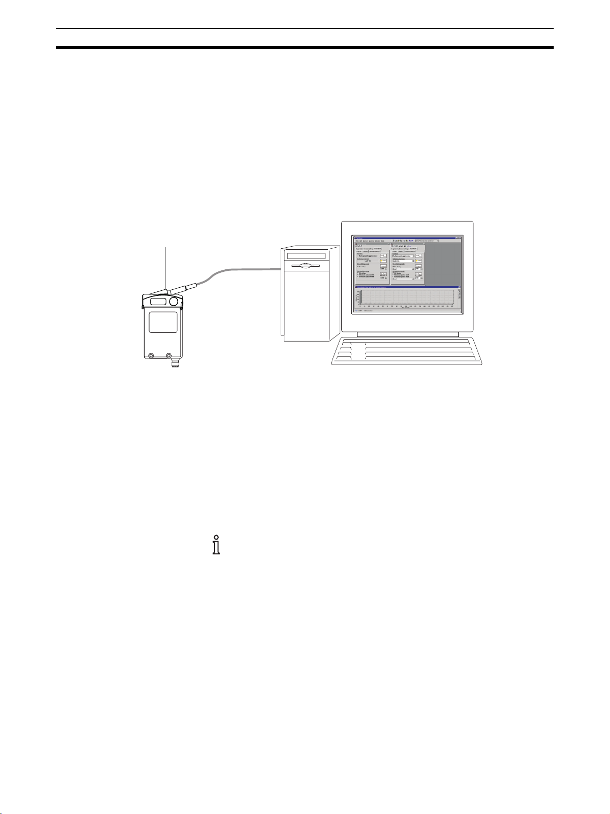
4-1 Connecting the sensor to the PC
The sensor is connected to the PC by means of the
data interface.
To do this, clip the data interface onto the sensor. Data is transferred between
the sensor and the data interface by means of an IR communication element.
The data interface is connected to a free serial COM port of the PC (COM1 …
COM8).
After the program has started, the SensorSupportSoftware runs an automatic interface check, including sensor selection and detection.
IR data interface
COM1 … COM8
PC
E3NT
OMRON E3NT-AL 232 2m
Figure 1 Connecting the sensor to the PC
Carry out the following actions:
1. Start the PC.
2. Clip the data interface onto the sensor.
3. Connect the connecting cable of the data interface to a free interface on
the PC (COM1 … COM8).
4. Switch on the sensor's operating voltage.
5. Start the SensorSupportSoftware (see SECTION 5 Program start).
The above actions can be carried out in any order.
14
Page 15

Program start
5-1 Starting the SensorSupportSoftware . . . . . . . . . . . . . . . . . . . . . . . . . . 16
SECTION 5
15
Page 16
Starting the SensorSupportSoftware Section 5-1
5-1 Starting the SensorSupportSoftware
• Start the program by double-clicking the SensorSupportSoftware pro-
gram icon in the OMRON\SensorSupportSoftware program group.
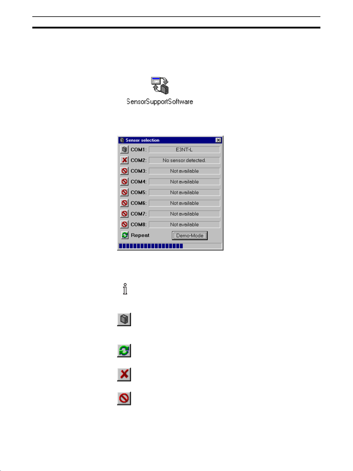
After the program has started, the SensorSupportSoftware runs an automatic interface check, including sensor selection and detection.
In this example, a sensor has been found at the serial COM1 interface. This
sensor's setting is read and the Sensor selection window is closed.
The Sensor selection window stays open if several sensors are
detected. In this window, the sensors found can be selected for setting
by clicking the relevant Sensor Selection button.
Sensor Selection
The sensors found are selected for setting by clicking the Sensor
Selection button.
Repeat
Sensor detection can be repeated by clicking the Repeat button.
No sensor detected
Indicates that no sensor is connected to the relevant interface.
Not available
Indicates that the relevant interface is not installed or is already
occupied.
16
Page 17
Starting the SensorSupportSoftware Section 5-1
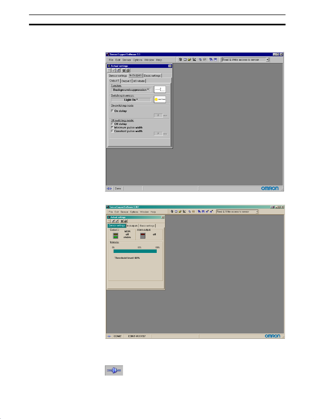
The starting screen is displayed. The starting screen can be different to the
depicted screen depending on the connected type of E3NT sensor.
E3NT-L
E3NT-R
The footer of the starting screen indicates which sensor is connected to
which interface and is active.
Online
Indicates the current connection status. Communication with the
sensor is possible.
17
Page 18
Starting the SensorSupportSoftware Section 5-1
Offline
Indicates the current connection status. Communication with the
sensor is not possible.
The current setting of the detected/selected sensor is displayed in the Actual
Settings window. The window of the current settings can be different to the
depicted window here depending on the connected type of E3NT sensor.
E3NT-L
18
Page 19
Starting the SensorSupportSoftware Section 5-1
E3NT-R
19
Page 20

Starting the SensorSupportSoftware Section 5-1
20
Page 21

Program definitions
6-1 Program control keys . . . . . . . . . . . . . . . . . . . . . . . . . . . . . . . . . . . . . . 22
SECTION 6
21
Page 22

Program control keys Section 6-1
6-1 Program control keys
The following program control keys are used in the SensorSupportSoftware:
Reset screen size
The active window is reseted to the full screen size.
Reduce window
The active window is displayed in a reduced size.
Expand window
The active window is displayed in an increased size.
Open file
Loads settings/diagram.
Save parameter
The current settings/diagrams in the active window or measurement
protocol data are saved.
Print
The current settings/diagrams in the active window or the settings of
the active window are printed.
Write to sensor
The current parameters are transferred to the sensor. This is only
possible if the Read & Write access to sensor mode is set.
Load from sensor
The current parameters are read from the sensor.
Decrease
Reduces the value by 1.
Increase
Increases the value by 1.
Start measurement
Starts the recording of the sensor value time chart.
Pause measurement
Pauses the recording of the sensor value time chart.
Erase / restart measurement
Erases the measurement or starts it again.
22
2D view
Changes to 2-dimensional view of the time chart.
Page 23

Program control keys Section 6-1
3D view
Changes to 3-dimensional view of the time chart.
Change page width
Increases the displayed range of the time chart.
Move one page left
Shifts the displayed range of the time chart to the left.
Move one page right
Shifts the displayed range of the time chart to the right.
Show switching distance A
Displays the setted switching distance A in the time chart.
Show switching distance B
Displays the setted switching distance B in the time chart.
Show switching distance C
Displays the setted switching distance C in the time chart.
Show switching distance D
Displays the setted switching distance D in the time chart.
23
Page 24

Program control keys Section 6-1
24
Page 25

Program operation
7-1 The main menu bar . . . . . . . . . . . . . . . . . . . . . . . . . . . . . . . . . . . . . . . 26
7-1-1 File menu item. . . . . . . . . . . . . . . . . . . . . . . . . . . . . . . . . . . . . 26
7-1-2 Edit menu item . . . . . . . . . . . . . . . . . . . . . . . . . . . . . . . . . . . . 26
7-1-3 Sensor menu item . . . . . . . . . . . . . . . . . . . . . . . . . . . . . . . . . . 27
7-1-4 Options menu item . . . . . . . . . . . . . . . . . . . . . . . . . . . . . . . . . 28
7-1-5 Window menu item . . . . . . . . . . . . . . . . . . . . . . . . . . . . . . . . . 28
7-1-6 Help menu item . . . . . . . . . . . . . . . . . . . . . . . . . . . . . . . . . . . . 28
7-2 Task bar buttons. . . . . . . . . . . . . . . . . . . . . . . . . . . . . . . . . . . . . . . . . . 29
7-3 Access mode . . . . . . . . . . . . . . . . . . . . . . . . . . . . . . . . . . . . . . . . . . . . 30
SECTION 7
25
Page 26

The main menu bar Section 7-1
7-1 The main menu bar
The main functions of the SensorSupportSoftware can be operated in the
main menu bar.
7-1-1 File menu item
Open
Opens a saved configuration file for a sensor in a new window.
xit
E
Exits the SensorSupportSoftware.
7-1-2 Edit menu item
Copy settings
Copies the marked text (in editing fields or in the text field Application
remarks).
P
aste settings
Pastes the marked text to cursor position (in editing fields or in the text field
Application remarks).
26
Page 27

The main menu bar Section 7-1
7-1-3 Sensor menu item
Sensor selection
Starts the automatic interface check with sensor selection (see Section 5-1
Starting the SensorSupportSoftware).
N
ew settings
Opens the New settings window (see Section 9-1 The program Update-
Sense). Calling up this menu item several times opens several windows.
In this window, the parameters can be modified and can be sent to the connected sensor.
T
imechart
Opens the Timechart window (see Section 8-3 Display window for graphical
evaluation Timechart of E3NT-L). Only one window can be opened.
In this window, the object's distance from the sensor can be displayed as a
function of time.
U
pdate the Firmware
Opens the update sense window (see Section 9-1 The program UpdateSense).
In this window, you can download a more up-to-date or a customised version
of the sensor operating firmware program to the sensor.
R
eset sensor
Returns the connected sensor to the factory default settings and loads the
standard setting. Refer also to the E3NT operating instructions (ABBO 0017)
in the appendix.
27
Page 28

The main menu bar Section 7-1
7-1-4 Options menu item
Language
In this menu item, you select the language version of the SensorSupport-
Software.
P
assword protection
The writing of new settings to the sensor can be protected with a password.
By this, unintentional modifying of the adjustments can be prevented (see
Section 7-3 Access mode).
7-1-5 Window menu item
Overlapping
Sorts opened windows in an overlapping arrangement.
A
Sorts opened windows in an adjacent arrangement.
7-1-6 Help menu item
SensorSupportSoftware Help
Displays the Software Description Cat.No. E30E-EN-01.
I
Displays information about the current software version.
rrange all
nformation
28
Page 29

Task bar buttons Section 7-2
7-2 Task bar buttons
By means of the function buttons, functions of the main menu bar can be
accessed swiftly and directly. Each function is identical to the items in the
main menu bar.
Sensor selection
Starts the automatic interface check with sensor selection (see Section 5-1 Starting the SensorSupportSoftware).
New settings
Opens the New settings window (see Section 9-1 The program
UpdateSense). Calling up this menu item several times opens sev-
eral windows.
In this window, the parameters can be modified and can be sent to
the connected sensor.
Open
Opens a a window with data of a saved configuration file (*.SSS).
Timechart
Opens the Timechart window Section 8-3 and Section 8-6. Only
one window can be opened.
In this window, the object's distance from the sensor can be displayed as a function of time.
Copy setting
Copies marked text.
Paste settings
Pastes copied text.
Overlapping
Sorts opened windows in an overlapping arrangement.
Arrange all
Sorts opened windows in an adjacent arrangement.
29
Page 30

Access mode Section 7-3
7-3 Access mode
By way of the access mode, you can define whether data may only be read
from the sensor or whether setting of the sensor is also permitted.
Read only access to sensor
Data may only be read from the sensor. Setting of the sensor is not permitted
(the programm control key Write to Sensor is deactivated)
Read & Write access to sensor
Data may be read from the sensor and setting by writing to the sensor is also
possible.
This function can be password-protected (see Section 7-1-4 Options menu
item).
30
Page 31

SECTION 8
Description of main windows
8-1 Window for display of the current sensor parameters Actual settings of E3NT-L. 32
8-1-1 Sensor settings tab . . . . . . . . . . . . . . . . . . . . . . . . . . . . . . . . . . . . . . . . . 33
8-1-2 In-/outputs tab . . . . . . . . . . . . . . . . . . . . . . . . . . . . . . . . . . . . . . . . . . . . . 34
8-1-3 Basic settings tab . . . . . . . . . . . . . . . . . . . . . . . . . . . . . . . . . . . . . . . . . . 36
8-2 Display window for new sensor settings New settings of E3NT-L . . . . . . . . . . . . 37
8-2-3 Basic settings tab . . . . . . . . . . . . . . . . . . . . . . . . . . . . . . . . . . . . . . . . . . 46
8-2-1 Sensor settings tab . . . . . . . . . . . . . . . . . . . . . . . . . . . . . . . . . . . . . . . . . 38
8-2-2 In-/outputs tab . . . . . . . . . . . . . . . . . . . . . . . . . . . . . . . . . . . . . . . . . . . . . 40
8-3 Display window for graphical evaluation Timechart of E3NT-L. . . . . . . . . . . . . . . 49
8-4 Window for display of the current sensor parameters Actual settings of E3NT-R 50
8-4-1 Sensor settings tab . . . . . . . . . . . . . . . . . . . . . . . . . . . . . . . . . . . . . . . . . 51
8-4-2 In-/outputs tab . . . . . . . . . . . . . . . . . . . . . . . . . . . . . . . . . . . . . . . . . . . . . 52
8-4-3 Basic settings tab . . . . . . . . . . . . . . . . . . . . . . . . . . . . . . . . . . . . . . . . . . 53
8-5 Display window for new sensor settings New settings of E3NT-R . . . . . . . . . . . . 54
8-5-1 In-/outputs tab . . . . . . . . . . . . . . . . . . . . . . . . . . . . . . . . . . . . . . . . . . . . . 55
8-5-2 Basic settings tab . . . . . . . . . . . . . . . . . . . . . . . . . . . . . . . . . . . . . . . . . . 60
8-6 Display window for graphical evaluation Timechart of E3NT-R . . . . . . . . . . . . . . 62
31
Page 32

Window for display of the current sensor parameters Actual settings of Section 8-1
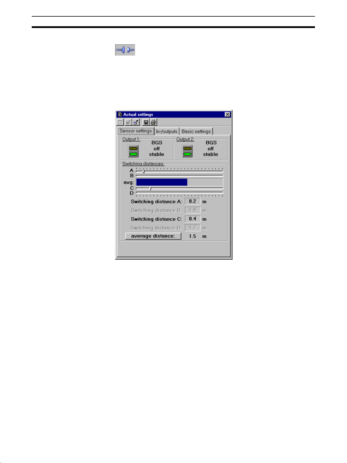
8-1 Window for display of the current sensor parameters
Actual settings of E3NT-L
The Actual settings window displays the current setting of the selected sensor on several tabs located one behind the other. The sensor cannot be set
via this window.
The window's display is constantly updated.
32
Page 33

Window for display of the current sensor parameters Actual settings of Section 8-1
8-1-1 Sensor settings tab
The current states of the outputs, the stability of the outputs and the setted
switching points are displayed in the Sensor settings menu.
Actuating the key average distance the display changed to the actual dis-
tance. Also in reverse direction.
33
Page 34

Window for display of the current sensor parameters Actual settings of Section 8-1
8-1-2 In-/outputs tab
In the In-/outputs tab, all parameters of the sensor that are related to the
inputs and outputs are displayed on three submenu tabs.
8-1-2-1 Output 1 submenu tab
The current parameters of Output 1 are displayed in the Output 1 submenu.
34
Page 35

Window for display of the current sensor parameters Actual settings of Section 8-1
8-1-2-2 Output 2 submenu tab
The current parameters of Output 2 are displayed in the Output 2 submenu.
8-1-2-3 I/O-mode submenu tab
The general input/output parameters such as pin assignments and the output
mode are displayed in the I/O-mode submenu.
35
Page 36

Window for display of the current sensor parameters Actual settings of Section 8-1
8-1-3 Basic settings tab
The general data of the selected sensor is displayed in the Basic settings
menu.
36
Page 37

Display window for new sensor settings New settings of E3NT-L Section 8-2
8-2 Display window for new sensor settings
New settings of E3NT-L
In the New settings window, the selected sensor can be set on several menu
tabs.
In this window, parameters can be read from the sensor and can be transferred to it. Settings can be created, modified, saved to data media, read from
data media and printed.
37
Page 38

Display window for new sensor settings New settings of E3NT-L Section 8-2
8-2-1 Sensor settings tab
In the Sensor settings menu, the switching points are teached or are setted
in different ways.
8-2-1-1 Teaching switching points
The switching points A to D are teached by clicking the teach buttons A to D.
That is to say, the object distance that has been measured at the time when
the teach button was pressed and is stored in the sensor as a relevant switching point after actuating the OK key.
The teach buttons B and D are only activated when the mode of the
Outputs 1 or 2 is set to window evaluation.
The teach buttons C and D are each activated when the Connector
pin 2 function has been set to Switching output 2 (see Section 8-2-23-1 Pin assignments).
38
Page 39

Display window for new sensor settings New settings of E3NT-L Section 8-2
8-2-1-2 Setting switching points
Switching points A to D can be set in the Switching distances box.
Actuating the key minimum distance the display changed to the maximum
distance. Also in reverse direction.
Switching points B and D and the sliders B and D can only be set if the
mode of the Outputs 1 or 2 has been set to window evaluation.
The Teach buttons C and D are each activated if the Connector pin 2
function has been set to Switching output 2 (see Section 8-2-2-3-1
Pin assignments).
The distance that is currently measured by the sensor is indicated by a
bar graph and as a numeric value under min/max.
The switching points can be set in several ways:
• By means of sliders A to D
The positions of the sliders can be altered by dragging with the mouse.
The resulting set switching distance is displayed under the sliders as a
numeric value for the relevant switching point.
• Number input in the case of Switching distances A to D
When Switching distance is selected, the switching distance of the relevant switching point can be entered as a number. The resulting set
switching distance is set on the relevant slider.
The numeric value can be increased or reduced with the adjacent Increment and Decrement buttons.
39
Page 40

Display window for new sensor settings New settings of E3NT-L Section 8-2
8-2-2 In-/outputs tab
In the In-/outputs tab, all parameters of the sensor that are related to inputs
and outputs can be set in three submenu tabs.
8-2-2-1 Output 1 submenu tab
The output parameters for Output 1 are set in the Output 1 submenu.
40
Page 41

Display window for new sensor settings New settings of E3NT-L Section 8-2
8-2-2-1-1 Function
The mode of the output is set in the Function box:
Background suppression BGS (factory default)
The background suppression mode can be set separately for both
outputs.
Measured objects are detected as from the blind zone up to the setted or teached switching point S
the setted or teached switching point S
Foreground suppression FGS
The foreground suppression mode can be set separately for both
outputs.
Measured objects are detected as from the setted or teached
switching point S
up to the maximum sensing distance. Objects in
A
the foreground, between the sensor and the setted or teached
switching point S
, are ignored.
A
Objects in the background, behind
A
, are ignored.
A
8-2-2-1-2 Switching inversion
Window evaluation
The window evaluation mode can be set separately for both outputs.
Measured objects are only detected in the measurement window
between the two setted or teached switching points (switching
zone). Objects outside of this measurement window in the foreground and in the background are ignored.
Switching inversion of the output is set in the Switching inversion box. This
parameter can be set separately for both outputs.
Light-On (factory default)
The output is active when one measured object is detected.
Dark-On
The output is active when no measured object is detected.
41
Page 42

Display window for new sensor settings New settings of E3NT-L Section 8-2
8-2-2-1-3 On-switching mode
The on delay of the output is set in the On-switching mode box. This param-
eter can be set separately for both outputs.
The on delay is activated or deactivated with the On delay checkbox.
In the Light-On mode, the on delay is the time from detection of an
object in the switching zone to activation of the relevant switching output.
The on delay can be set in several ways:
• By slider
The position of this slider can be altered with the mouse.
The resulting set delay is displayed next to the slider as a number.
This number can be increased or reduced with the slider's Increment and
Decrement buttons.
• With number input
The delay can also be entered directly as a number. The slider is adjusted
accordingly.
The On delay cannot be activated, if Off delay is set to minimum
pulse width or constant pulse width.
42
Page 43

Display window for new sensor settings New settings of E3NT-L Section 8-2
8-2-2-1-4 Off-switching mode
The nature and the numeric value of the output's switching response are set
in the Off-switching mode box. This parameter can be set separately for
both outputs.
The timing response described here is referred to the Light-on switch-
ing inversion.
The behaviour of the individual off delay modes is inverted in the Dark-
on switching inversion mode.
The nature of the off-switching response is chosen in checkboxes:
Off delay
The off delay starts as from the time when the measured object
leaves the sensing zone. The output does not become inactive until
the off delay has elapsed.
Minimum pulse width
After detection of a measured object, the output remains active for
at least the setted off delay. If the measured object dwells in the
sensing zone for longer than the setted off delay, the output
becomes inactive immediately after the object leaves the sensing
zone.
Constant pulse width (one shot)
After detection of a measured object, the output only remains active
for the setted off delay and becomes inactive after this time has
elapsed, regardless of the object's dwell time, even if the measured
object dwells in the sensing zone for longer than the setted off delay.
Minimum pulse width and Constant pulse width are not activatable,
if On delay is activated.
The time can be set in several ways:
• By slider
The position of the slider can be varied with the mouse. The resulting set
time is displayed as a number next to the slider.
The number can be increased or reduced with the Increment and Decrement buttons of the slider.
• With number input
The time can also be entered directly as a number. The slider is adjusted
accordingly.
43
Page 44

Display window for new sensor settings New settings of E3NT-L Section 8-2
8-2-2-2 Output 2 submenu tab
The output parameters for Output 2 are set in the Output 2 submenu.
Output 2 is set in the same way as described for Output 1 (see Section 8-2-2-
1 Output 1 submenu tab).
8-2-2-3 I/O-Mode submenu tab
The general parameters of Outputs 1 and 2 are set in the I/O-Mode submenu.
44
Page 45

Display window for new sensor settings New settings of E3NT-L Section 8-2
8-2-2-3-1 Pin assignments
The functions of Connector pin 2 and Connector pin 5 are set in the Pin
Assignment box.
In total, the sensor can be operated with a maximum of three inputs/outputs,
and a maximum of two outputs is possible at the same time.
The functions of the inputs/outputs can be set in the following order:
Connector pin 4 is always defined as Output 1 (OUT1) and cannot be modi-
fied.
Connector pin 2 can be set as Switching output 2 (OUT2), teaching input
(TEACH) for the switching points A and C or as the test input (TEST) or trigger input (TRIG).
Connector pin 5 can be set as the trigger input (TRIG), teaching input
(TEACH) for the switching points A to D or as the test input (TEST).
• Teaching input TEACH
If a signal in the operating voltage range (at least 10 V) is applied to this
input, the switching point A, B, C or D is teached, depending on the settings, and analogously to the Teach buttons (see Section 8-2-1-1 Teaching
switching points).
• Test input TEST
The emitter is deactivated if a signal in the operating voltage range (at
least 10 V) is applied to this input.
If the sensor is in the light-on state, the receiver detects the absence of
the emitted light reflected by the measured object, regardless of the setted switching points.
The output state changes.
This function can be used to test correct functioning of the sensor.
• Trigger input TRIG
If a signal in the operating voltage range is applied to this input, the sensor is requested to start a measurement (object distance).
The sensor rate (response time) can be increased by the trigger function.
• Switching outputs OUT1 and OUT2
The switching outputs switch when a measured object is detected and in
accordance with the sensor's settings.
45
Page 46

Display window for new sensor settings New settings of E3NT-L Section 8-2
8-2-2-3-2 Output mode
The output circuit is set in the Output mode box. The output circuit can be set
jointly for both outputs:
• PNP, plus-switching, open collector
• NPN, minus-switching, open collector
• Complementary, push-pull, plus/minus-switching (factory default setting)
The sensor is set by default to the push-pull output (complementary). In this
output setting, both output transistors are alternately active.
When the output circuit is set to PNP or NPN, the relevant output circuit that is
currently not in use is switched off.
Both output circuits are resistant to short-circuits and are polarity-safe.
8-2-3 Basic settings tab
The general parameters of the selected sensor are set in the Basic settings
menu.
46
Page 47

Display window for new sensor settings New settings of E3NT-L Section 8-2
8-2-3-1 Application remarks
In the Application remarks box, you can enter remarks that are saved
together with the settings.
When the file is read again, the remarks again appear in the Application
remarks box.
8-2-3-2 Display at sensor
The type of display on the sensor can be set in the Display at sensor box.
8-2-3-2-1 Type of display
The following display formats are available for selection in the pulldown
menu of this box:
• Display in m
The current sensing distance is displayed in m on the sensor's display.
• Display of column
The current sensing distance is displayed on the sensor's display as a bar
graph
8-2-3-2-2 Rotating the display by 180°
• Display rotated checkbox
When this checkbox is marked, the display on the sensor's display is
rotated by 180°.
This function may be useful when the sensor if fitted in certain positions.
8-2-3-2-3 Economy mode
• Economy mode checkbox
When this checkbox is marked, the sensor's display mode is set to the
energy saving mode.
In the energy saving mode, the display switches off automatically approximately 5 minutes after the last time a push button has been pressed on
the sensor.
47
Page 48

Display window for new sensor settings New settings of E3NT-L Section 8-2
8-2-3-3 Locking of sensor
The following locking modes are available for selection in the pulldown menu
of this box:
• No locking
The sensor is not locked. It can be set by push button and PC. The display on the sensor is active.
• Keylock
With the key lock function, the push buttons on the sensor can be locked
to prevent unintentional changing of the settings.
The lock can be switched on and off on the sensor.
When the key lock is active, changes can only be made after the Minus
and Plus buttons are pressed simultaneously for 4 seconds. This temporarily suppresses the key lock. If no buttons are pressed for about 5 minutes, the key lock is automatically activated again.
• Complete sensor locking
The sensor is completely locked. It cannot be set by push buttons and
PC. When a button is pressed, the display always stays in the normal
mode (analog value display/bar graph).
8-2-3-4 Heating (only available for E3NT-LH@@)
The following window heating modes are available for selection in the pulldown menu of this box:
• Heating off
The sensor window heating is switched off.
• Heating on
The sensor window heating is permanently on.
• Automatic
The heating is adjusted automatically depending on the ambient temperature.
48
Page 49

Display window for graphical evaluation Timechart of E3NT-L Section 8-3
8-3 Display window for graphical evaluation
Timechart of E3NT-L
In the Timechart window, the measured distance of the sensor is displayed
graphically as a function of time.
49
Page 50

Window for display of the current sensor parameters Actual settings of Section 8-4
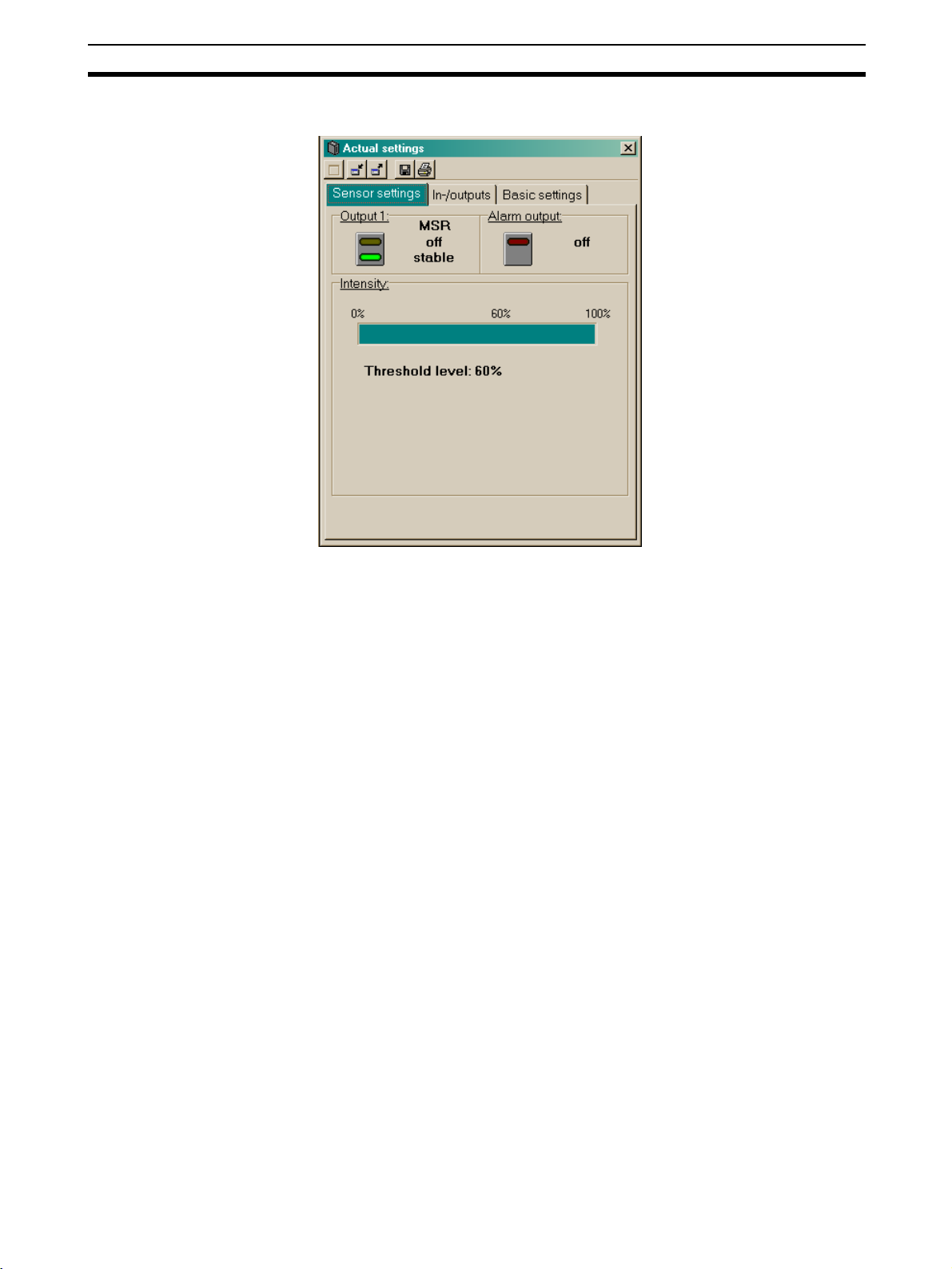
8-4 Window for display of the current sensor parameters
Actual settings of E3NT-R
The Actual settings window displays the current setting of the selected sensor on several tabs located one behind the other. The sensor cannot be set
via this window.
The window's display is constantly updated.
50
Page 51

Window for display of the current sensor parameters Actual settings of Section 8-4
8-4-1 Sensor settings tab
The current states of the sensor’s output, the stability of the sensor output and
the alarm output are displayed in the Sensor settings menu.
Also the received light intensity is depicted in this window.
51
Page 52

Window for display of the current sensor parameters Actual settings of Section 8-4
8-4-2 In-/outputs tab
In the In-/outputs tab, all parameters of the sensor that are related to the
inputs and outputs are displayed on two submenu tabs.
8-4-2-1 Output 1 submenu tab
The current parameters of Output 1 are displayed in the Output 1 submenu.
52
Page 53

Window for display of the current sensor parameters Actual settings of Section 8-4
8-4-2-2 I/O-mode submenu tab
The general input/output parameters such as pin assignments and the output
function are displayed in the I/O-mode submenu.
8-4-3 Basic settings tab
The general data of the selected sensor is displayed in the Basic settings
menu.
53
Page 54

Display window for new sensor settings New settings of E3NT-R Section 8-5
8-5 Display window for new sensor settings
New settings of E3NT-R
In the New settings window, the selected sensor can be set on several menu
tabs located behind one another.
In this window, parameters can be read from the sensor and can be transferred to it. Settings can be created, modified, saved to data media and read
from data media and printed.
54
Page 55

Display window for new sensor settings New settings of E3NT-R Section 8-5
8-5-1 In-/outputs tab
In the In-/outputs tab, all parameters of the sensor that are related to inputs
and outputs can be set in two submenu tabs.
8-5-1-1 Output submenu tab
The output parameters for the Output are set in the Output 1 submenu.
55
Page 56

Display window for new sensor settings New settings of E3NT-R Section 8-5
8-5-1-1-1 Switching inversion
Switching inversion of the output is set in the Switching inversion box.
Light-On
The output is active when the light beam is received via the reflector
on the receiver.
Dark-On (factory default)
The output is active when an object is interrupting the light beam
between sensor and reflector.
8-5-1-1-2 On-switching mode
The on delay of the output is set in the On-switching mode box.
The on delay is activated or deactivated with the On delay checkbox.
In the Dark-On mode, the on delay is the time from detection of an
object in the switching zone to activation of the switching output.
The on delay can be set in several ways:
• By slider
The position of this slider can be altered by dragging with the mouse.
The resulting set delay is displayed next to the slider as a number.
This number can be increased or reduced with the slider's Increment and
Decrement buttons.
• With number input
The delay can also be entered directly as a number. The slider is adjusted
accordingly.
The On delay cannot be activated, if Off delay is set to minimum
pulse width or constant pulse width.
56
Page 57

Display window for new sensor settings New settings of E3NT-R Section 8-5
8-5-1-1-3 Off-switching mode
The mode and the numeric value of the output's switching response are set in
the Off-switching mode box. This parameter can be set separately for both
outputs.
The timing response described here is referred to the Light-on switch-
ing inversion.
The behaviour of the individual off delay modes is inverted in the Dark-
on switching inversion mode.
The nature of the off-switching response is chosen in checkboxes:
Off delay
The off delay starts as from the time when the measured object
leaves the sensing zone. The output does not become inactive until
the off delay has elapsed.
Minimum pulse width
After detection of a measured object, the output remains active for
at least the setted off delay. If the measured object dwells in the
sensing zone for longer than the setted off delay, the output
becomes inactive immediately after the object leaves the sensing
zone.
Constant pulse width (one shot)
After detection of a measured object, the output only remains active
for the setted off delay and becomes inactive after this time has
elapsed, regardless of the object's dwell time, even if the measured
object dwells in the sensing zone for longer than the setted off delay.
Minimum pulse width and Constant pulse width cannot be activated, if On delay is activated.
The time can be set in several ways:
• By slider
The position of the slider can be varied by dragging with the mouse. The
resulting set time is displayed as a number next to the slider.
The number can be increased or reduced with the Increment and Decrement buttons of the slider.
• With number input
The time can also be entered directly as a number. The slider is adjusted
accordingly.
57
Page 58

Display window for new sensor settings New settings of E3NT-R Section 8-5
8-5-1-2 I/O-Mode submenu tab
The general parameters of Outputs 1 and 2 are set in the I/O-Mode submenu.
8-5-1-2-1 Pin assignments
The functions of Connector pin 2 and Connector pin 5 are set in the Pin
Assignment box.
In total, the sensor can be operated with a maximum of three inputs/outputs,
and a maximum of two outputs is possible at the same time.
The functions of the inputs/outputs can be set in the following order:
Connector pin 4 is always defined as Output 1 (OUT1) and cannot be modi-
fied.
Connector pin 2 can be set as test input (TEST) or alarm output
(ALARM).
Connector pin 5 can be set as the test input (TEST) or deactivated.
• Test input TEST
The emitter is deactivated if a signal in the operating voltage range (at
least 10 V) is applied to this input.
If the sensor is in the light-on state, the receiver detects the absence of
the emitted light reflected by the measured object.
The output state changes.
58
Page 59

Display window for new sensor settings New settings of E3NT-R Section 8-5
This function can be used to test correct functioning of the sensor.
• Alarm output ALARM
The outputs switch when a the sensor works in an unstable mode due to
dirt on the window or other critical detection conditions (e.g. steamy and
foggy environment).
8-5-1-2-2 Output mode
The output circuit is set in the Output mode box. The output circuit can be set
jointly for both outputs:
• PNP, plus-switching, open collector
• NPN, minus-switching, open collector
• Complementary, push-pull, plus/minus-switching (factory default setting)
The sensor is set by default to the push-pull output (complementary). In this
output setting, both output transistors are alternately active.
When the output circuit is set to PNP or NPN, the relevant output circuit that is
currently not in use is switched off.
Both output circuits are resistant to short-circuits and are polarity-safe.
59
Page 60

Display window for new sensor settings New settings of E3NT-R Section 8-5
8-5-2 Basic settings tab
The general parameters of the selected sensor are set in the Basic settings
menu.
8-5-2-1 Application remarks
In the Application remarks box, you can enter remarks that are saved
together with the settings.
When the file is read again, the remarks again appear in the Application
remarks box.
8-5-2-2 Display at sensor
The type of display on the sensor can be set in the Display at sensor box.
8-5-2-2-1 Rotating the display by 180°
60
Page 61

Display window for new sensor settings New settings of E3NT-R Section 8-5
• Display rotated checkbox
When this checkbox is marked, the display on the sensor's display is
rotated by 180°.
This function may be useful when the sensor if fitted in certain positions.
8-5-2-2-2 Economy mode
• Economy mode checkbox
When this checkbox is marked, the sensor's display mode is set to the
energy saving mode.
In the energy saving mode, the display switches off automatically approximately 5 minutes after the last time a push button has been pressed on
the sensor.
8-5-2-3 Locking of sensor
The following locking modes are available for selection in the pulldown menu
of this box:
• No locking
The sensor is not locked. It can be set by push button and PC. The display on the sensor is active.
• Keylock
With the key lock function, the push buttons on the sensor can be locked
to prevent unintentional changing of the settings.
The lock can be switched on and off on the sensor.
When the key lock is active, changes can only be made after the Minus
and Plus buttons are pressed simultaneously for 4 seconds. This temporarily suppresses the key lock. If no buttons are pressed for about 5 minutes, the key lock is automatically activated again.
• Complete sensor locking
The sensor is completely locked. It cannot be set by push buttons and
PC. When a button is pressed, the display always stays in the normal
mode (analog value display/bar graph).
8-5-2-4 Heating (only available for E3NT-RH@@)
The following window heating modes are available for selection in the pulldown menu of this box.
• Heating off
The sensor window heating is switched off.
• Heating on
The sensor window heating is permanently on.
61
Page 62

Display window for graphical evaluation Timechart of E3NT-R Section 8-6
• Automatic
The heating is adjusted automatically depending on the ambient temperature (default setting)
8-6 Display window for graphical evaluation
Timechart of E3NT-R
In the Timechart window, the measured received light intensity of the sensor
is displayed graphically as a function of time.
62
Page 63

Update the sensor firmware
9-1 The program UpdateSense . . . . . . . . . . . . . . . . . . . . . . . . . . . . . . . . . 64
9-1-1 The menu bar . . . . . . . . . . . . . . . . . . . . . . . . . . . . . . . . . . . . . 64
9-1-2 The function bar . . . . . . . . . . . . . . . . . . . . . . . . . . . . . . . . . . . 66
9-1-3 Display in details . . . . . . . . . . . . . . . . . . . . . . . . . . . . . . . . . . . 66
SECTION 9
63
Page 64

The program UpdateSense Section 9-1
9-1 The program UpdateSense
The program UpdateSense can be used to update the sensor's operating
firmware program or to load a special customised sensor program into the
sensor.
The current status of the update and any error messages are displayed in the
Status information line.
Firmware files are stored in HEX format.
The latest version of the sensor's operating firmware program can be down-
loaded from the Internet address http://www.eu.omron.com.
9-1-1 The menu bar
9-1-1-1 File menu item
The functions of UpdateSense can be operated by way of the menu bar.
Open file
Opens a firmware file (*.hex) for a sensor.
S
ave file
Saves a firmware file for a sensor.
Close p
Ends the UpdateSense program.
rogram
64
Page 65

The program UpdateSense Section 9-1
9-1-1-2 Port menu item
The interface to which the sensor is connected is selected in the Port menu
item.
9-1-1-3 Transfer menu item
Transfer of new firmware to the sensor is started or cancelled in the Transfer
menu item.
Loading progress is shown as a bar graph.
9-1-1-4 Help menu item
UpdateSense-Help
Displays help files about the UpdateSense program.
nformation
I
Displays information about the UpdateSense program.
65
Page 66

The program UpdateSense Section 9-1
9-1-2 The function bar
Functions of the menu bar can be accessed swiftly and directly by way of the
function bar.
Open
Opens a firmware file (*.hex) for a sensor.
Interface pulldown menu
With the I
through which the sensor is connected.
Start upload
Starts transfer of new firmware to the sensor.
Loading progress is displayed as a bar graph.
Save
Saves a firmware file for a sensor (only if Detail is activated).
nterface pulldown menu, you select the interface
9-1-3 Display in details
The additional Details window is opened when you click the Details button.
In this window, you can monitor the data transfer report and the firmware file
(Hex file) for the update.
This information is of interest to trained product specialists only.
66
 Loading...