

Page 1

Cat. No. W404-E1-07
DRT2 Series
DeviceNet Slaves
OPERATION MANUAL
Page 2

DRT2 Series DeviceNet Slaves
Operation Manual
Revised April 2008
Page 3

iv
Page 4

Notice:
r
f
OMRON products are manufactured for use according to proper procedures by a qualified operator
and only for the purposes described in this manual.
The following conventions are used to indicate and classify precautions in this manual. Always heed
the information provided with them. Failure to heed precautions can result in injury to people or damage to property.
!DANGER Indicates an imminently hazardous situation which, if not avoided, will result in death or
serious injury. Additionally, there may be severe property damage.
!WARNING Indicates a potentially hazardous situation which, if not avoided, could result in death or
serious injury. Additionally, there may be severe property damage.
!Caution Indicates a potentially hazardous situation which, if not avoided, may result in minor or
moderate injury, or property damage.
OMRON Product References
All OMRON products are capitalized in this manual. The word “Unit” is also capitalized when it refers to
an OMRON product, regardless of whether or not it appears in the proper name of the product.
The abbreviation “Ch,” which appears in some displays and on some OMRON products, often means
“word” and is abbreviated “Wd” in documentation in this sense.
The abbreviation “PLC” means Programmable Controller. “PC” is used, however, in some Programming Device displays to mean Programmable Controller.
Visual Aids
The following headings appear in the left column of the manual to help you locate different types of
information.
OMRON, 2002
All rights reserved. No part of this publication may be reproduced, stored in a retrieval system, or transmitted, in any form, o
by any means, mechanical, electronic, photocopying, recording, or otherwise, without the prior written permission o
OMRON.
No patent liability is assumed with respect to the use of the information contained herein. Moreover, because OMRON is constantly striving to improve its high-quality products, the information contained in this manual is subject to change without
notice. Every precaution has been taken in the preparation of this manual. Nevertheless, OMRON assumes no responsibility
for errors or omissions. Neither is any liability assumed for damages resulting from the use of the information contained in
this publication.
Note Indicates information of particular interest for efficient and convenient opera-
tion of the product.
1,2,3... 1. Indicates lists of one sort or another, such as procedures, checklists, etc.
v
Page 5

vi
Page 6

TABLE OF CONTENTS
PRECAUTIONS . . . . . . . . . . . . . . . . . . . . . . . . . . . . . . . . . . . xv
1 Intended Audience. . . . . . . . . . . . . . . . . . . . . . . . . . . . . . . . . . . . . . . . . . . . . . . . . . . . . . . . . xvi
2 General Precautions. . . . . . . . . . . . . . . . . . . . . . . . . . . . . . . . . . . . . . . . . . . . . . . . . . . . . . . . xvii
3 Safety Precautions . . . . . . . . . . . . . . . . . . . . . . . . . . . . . . . . . . . . . . . . . . . . . . . . . . . . . . . . . xviii
4 Operating Environment Precautions . . . . . . . . . . . . . . . . . . . . . . . . . . . . . . . . . . . . . . . . . . . xix
5 Application Precautions. . . . . . . . . . . . . . . . . . . . . . . . . . . . . . . . . . . . . . . . . . . . . . . . . . . . .xx
6 Conformance to EC Directives . . . . . . . . . . . . . . . . . . . . . . . . . . . . . . . . . . . . . . . . . . . . . . . xxii
SECTION 1
Smart Slaves and Features . . . . . . . . . . . . . . . . . . . . . . . . . . . 1
1-1 DRT2 Features . . . . . . . . . . . . . . . . . . . . . . . . . . . . . . . . . . . . . . . . . . . . . . . . . . . . . . . . . . . . 2
1-2 DRT2 Slaves . . . . . . . . . . . . . . . . . . . . . . . . . . . . . . . . . . . . . . . . . . . . . . . . . . . . . . . . . . . . . 7
SECTION 2
Example System Startup . . . . . . . . . . . . . . . . . . . . . . . . . . . . 21
2-1 Basic Procedures and Configuration Examples. . . . . . . . . . . . . . . . . . . . . . . . . . . . . . . . . . . 22
2-2 Preparations . . . . . . . . . . . . . . . . . . . . . . . . . . . . . . . . . . . . . . . . . . . . . . . . . . . . . . . . . . . . . . 23
2-3 Setting and Wiring Hardware . . . . . . . . . . . . . . . . . . . . . . . . . . . . . . . . . . . . . . . . . . . . . . . . 24
2-4 Starting Communications . . . . . . . . . . . . . . . . . . . . . . . . . . . . . . . . . . . . . . . . . . . . . . . . . . .27
2-5 Checking Operation. . . . . . . . . . . . . . . . . . . . . . . . . . . . . . . . . . . . . . . . . . . . . . . . . . . . . . . . 29
SECTION 3
Common Slave Specifications . . . . . . . . . . . . . . . . . . . . . . . . 31
3-1 Common Slave Specifications . . . . . . . . . . . . . . . . . . . . . . . . . . . . . . . . . . . . . . . . . . . . . . . 32
3-2 DeviceNet Remote I/O Communications . . . . . . . . . . . . . . . . . . . . . . . . . . . . . . . . . . . . . . . 34
SECTION 4
Functions of All Slaves, General-purpose Slaves,
and Environment-resistive Slaves . . . . . . . . . . . . . . . . . . . . . 47
4-1 Maintenance Mode Window and Main Window . . . . . . . . . . . . . . . . . . . . . . . . . . . . . . . . . . 48
4-2 Common Slave Functions . . . . . . . . . . . . . . . . . . . . . . . . . . . . . . . . . . . . . . . . . . . . . . . . . . . 52
4-3 Functions of General-purpose Slaves and Environment-resistive Slaves . . . . . . . . . . . . . . . 61
SECTION 5
General-purpose Slaves . . . . . . . . . . . . . . . . . . . . . . . . . . . . . 83
5-1 Common Specifications for General-purpose Slaves . . . . . . . . . . . . . . . . . . . . . . . . . . . . . . 85
5-2 Connecting Communications Cables to General-purpose Slaves . . . . . . . . . . . . . . . . . . . . . 87
5-3 Mounting Terminating Resistors . . . . . . . . . . . . . . . . . . . . . . . . . . . . . . . . . . . . . . . . . . . . . . 91
5-4 Maintenance Information Window . . . . . . . . . . . . . . . . . . . . . . . . . . . . . . . . . . . . . . . . . . . . 91
5-5 Remote I/O Terminals with Transistors . . . . . . . . . . . . . . . . . . . . . . . . . . . . . . . . . . . . . . . . 97
5-6 Connector Terminals with Transistors. . . . . . . . . . . . . . . . . . . . . . . . . . . . . . . . . . . . . . . . . . 144
5-7 Screw-less Clamp Terminals . . . . . . . . . . . . . . . . . . . . . . . . . . . . . . . . . . . . . . . . . . . . . . . . 203
vii
Page 7

TABLE OF CONTENTS
SECTION 6
Environment-resistive Slaves. . . . . . . . . . . . . . . . . . . . . . . . . 233
6-1 Common Specifications for Environment-resistive Slaves . . . . . . . . . . . . . . . . . . . . . . . . . . 234
6-2 Connecting Communications Cables to Environment-resistive Slaves . . . . . . . . . . . . . . . . . 236
6-3 Maintenance Information Window . . . . . . . . . . . . . . . . . . . . . . . . . . . . . . . . . . . . . . . . . . . . 239
6-4 Advanced Environment-resistive Terminals . . . . . . . . . . . . . . . . . . . . . . . . . . . . . . . . . . . . . 245
6-5 Standard Environment-resistive Terminals . . . . . . . . . . . . . . . . . . . . . . . . . . . . . . . . . . . . . . 260
6-6 Mounting and Wiring Environment-resistive Slaves. . . . . . . . . . . . . . . . . . . . . . . . . . . . . . . 286
SECTION 7
Analog Slaves. . . . . . . . . . . . . . . . . . . . . . . . . . . . . . . . . . . . . . 291
7-1 Overview of Analog Slaves . . . . . . . . . . . . . . . . . . . . . . . . . . . . . . . . . . . . . . . . . . . . . . . . . . 292
7-2 Common Procedures . . . . . . . . . . . . . . . . . . . . . . . . . . . . . . . . . . . . . . . . . . . . . . . . . . . . . . . 308
7-3 Maintenance Information Window . . . . . . . . . . . . . . . . . . . . . . . . . . . . . . . . . . . . . . . . . . . . 310
7-4 Analog Input Terminals . . . . . . . . . . . . . . . . . . . . . . . . . . . . . . . . . . . . . . . . . . . . . . . . . . . . . 315
7-5 Analog Output Terminals . . . . . . . . . . . . . . . . . . . . . . . . . . . . . . . . . . . . . . . . . . . . . . . . . . .359
7-6 Temperature Input Terminals. . . . . . . . . . . . . . . . . . . . . . . . . . . . . . . . . . . . . . . . . . . . . . . . . 377
SECTION 8
Communications Timing . . . . . . . . . . . . . . . . . . . . . . . . . . . . 443
8-1 Remote I/O Communications Characteristics . . . . . . . . . . . . . . . . . . . . . . . . . . . . . . . . . . . . 444
8-2 Message Communications Characteristics . . . . . . . . . . . . . . . . . . . . . . . . . . . . . . . . . . . . . . 453
SECTION 9
Troubleshooting and Maintenance . . . . . . . . . . . . . . . . . . . . 455
9-1 Indicators and Error Processing. . . . . . . . . . . . . . . . . . . . . . . . . . . . . . . . . . . . . . . . . . . . . . . 456
9-2 Troubleshooting. . . . . . . . . . . . . . . . . . . . . . . . . . . . . . . . . . . . . . . . . . . . . . . . . . . . . . . . . . . 457
9-3 Maintenance. . . . . . . . . . . . . . . . . . . . . . . . . . . . . . . . . . . . . . . . . . . . . . . . . . . . . . . . . . . . . . 466
Appendices
A DeviceNet Explicit Messages . . . . . . . . . . . . . . . . . . . . . . . . . . . . . . . . . . . . . . . . . . . . . . . 469
B Using Another Company's Master Unit . . . . . . . . . . . . . . . . . . . . . . . . . . . . . . . . . . . . . . . . 493
C Restrictions on Reading Total ON Time/Contact Operation Counter
for All Slaves at Once . . . . . . . . . . . . . . . . . . . . . . . . . . . . . . . . . . . . . . . . . . . . . . . . . . . . . . 539
D Connectable Devices . . . . . . . . . . . . . . . . . . . . . . . . . . . . . . . . . . . . . . . . . . . . . . . . . . . . . .553
E Current Consumption Summary . . . . . . . . . . . . . . . . . . . . . . . . . . . . . . . . . . . . . . . . . . . . . . 563
F Precautions with Connecting Two-wire DC Sensors . . . . . . . . . . . . . . . . . . . . . . . . . . . . . . 567
Index. . . . . . . . . . . . . . . . . . . . . . . . . . . . . . . . . . . . . . . . . . . . . 569
Revision History . . . . . . . . . . . . . . . . . . . . . . . . . . . . . . . . . . . 575
viii
Page 8

About this Manual:
This manual describes the installation and operation of an DeviceNet Smart Slave Units and includes
the sections described below.
Please read this manual carefully and be sure you understand the information provided before
attempting to install or operate the DeviceNet Smart Slave Units. Be sure to read the precautions
provided in the following section.
The following manuals also cover information related to DeviceNet applications. Use the DeviceNet
Operation Manual together with other required manuals.
Manual Contents Cat. No.
DeviceNet
Operation Manual
DeviceNet Masters
Operation Manual
DeviceNet CS/CJ Series Units
Operation Manual
DeviceNet DRT2 Series
Slaves Operation Manual (this
manual)
DeviceNet DRT1 Series
Slaves Operation Manual
DeviceNet Configurator Ver.
2.@ Operation Manual
DeviceNet MULTIPLE I/O
TERMINAL Operation Manual
Describes the configuration and construction of a DeviceNet network,
including installation procedures and specifications for cables, connectors, and other connection devices, as well as information on functions,
operating procedures, and applications.
Describes the models, specifications, functions, operating procedures,
and applications of C200HX/HG/HE, CVM1, and CV-series DeviceNet
Master Units.
Describes the models, specifications, functions, operating procedures,
and applications of CS-series and CJ-series DeviceNet Master Units.
Describes the models, specifications, functions, operating procedures,
and applications of DRT2-series Smart Slave Units.
Describes the models, specifications, functions, operating procedures,
and applications of DRT1-series Smart Slave Units.
Describes the operating procedures of the DeviceNet Configurator. W382
Describes the models, specifications, functions, operating procedures,
and applications of the DeviceNet MULTIPLE I/O TERMINALs.
W267
W379
W380
W404
W347
W348
Precautions provides general precautions for planning, installing, and operating the DeviceNet DRT2series Smart Slaves and related devices.
Section 1 provides an overview of the DeviceNet DRT2-series Smart Slaves, including lists of models,
and information on features that were not included in the DRT1-series Slaves.
Section 2 provides information on hardware aspects of Masters and Slaves connected to a DeviceNet
Network to ensure the proper operation of the system. Included are system configuration examples,
basic procedures for wiring, details on mounting and setting Master and Slave Units, procedures for
connecting cables and power supplies, creating I/O tables, creating and registering scan lists, and
checking operation of the system.
Section 3 provides specifications and indicator displays that are common to all Slaves. The allocation
of remote I/O memory for Smart Slaves is also described here.
Section 4 describes the functions of DRT2-series Smart Slaves and their applications, including operation procedures using a DeviceNet Configurator.
Section 5 provides the specifications and describes the components, terminal arrangements, basic
procedures for wiring, and methods for connecting cables of General-purpose Slaves. Information on
Slave settings, mounting and wiring methods are also provided separately for each Slave type.
Section 6 provides the specifications and describes the components, terminal arrangements, basic
procedures for wiring, and methods for connecting cables of Environment-resistive Slaves (conforming
to IP67). Information on Slave settings, mounting and wiring methods are also provided separately for
each Slave type.
ix
Page 9

About this Manual, Continued
Section 7 provides the specifications, terminal arrangements, mounting procedures, and connection
methods of Analog I/O Terminals. Information is included on types of I/O data that can be allocated,
allocation methods and procedures, and math operation processing. Setting methods using the Configurator are also described.
Section 8 provides information on the time required for a complete communications cycle, for an output response to be made to an input, to start the system, and to send messages.
Section 9 describes error processing, periodic maintenance operations, and troubleshooting procedures needed to keep the DeviceNet Network operating properly. We recommend reading through the
error processing procedures in both this manual and the operation manual for the master being used
before operation so that operating errors can be identified and corrected more quickly.
Appendix A provides lists of DeviceNet explicit messages and their basic format.
Appendix B provides information on using masters from other companies and Slave device profiles
necessary for multi-vendor applications, including information on installing EDS files.
Appendix C describes restrictions on reading the total ON time and contact operation counter for all
Slaves at once.
Appendix D provides lists of standard models of DRT2-series Smart Slaves and connectable devices.
Appendix E shows the current consumptions of DRT2-series Smart Slaves.
Appendix F provides precautions for connecting two-wire DC sensors.
!WARNING Failure to read and understand the information provided in this manual may result in per-
sonal injury or death, damage to the product, or product failure. Please read each section
in its entirety and be sure you understand the information provided in the section and
related sections before attempting any of the procedures or operations given.
x
Page 10

Read and Understand this Manual
Please read and understand this manual before using the product. Please consult your OMRON
representative if you have any questions or comments.
Warranty and Limitations of Liability
WARRANTY
OMRON's exclusive warranty is that the products are free from defects in materials and workmanship for a
period of one year (or other period if specified) from date of sale by OMRON.
OMRON MAKES NO WARRANTY OR REPRESENTATION, EXPRESS OR IMPLIED, REGARDING NONINFRINGEMENT, MERCHANTABILITY, OR FITNESS FOR PARTICULAR PURPOSE OF THE
PRODUCTS. ANY BUYER OR USER ACKNOWLEDGES THAT THE BUYER OR USER ALONE HAS
DETERMINED THAT THE PRODUCTS WILL SUITABLY MEET THE REQUIREMENTS OF THEIR
INTENDED USE. OMRON DISCLAIMS ALL OTHER WARRANTIES, EXPRESS OR IMPLIED.
LIMITATIONS OF LIABILITY
OMRON SHALL NOT BE RESPONSIBLE FOR SPECIAL, INDIRECT, OR CONSEQUENTIAL DAMAGES,
LOSS OF PROFITS OR COMMERCIAL LOSS IN ANY WAY CONNECTED WITH THE PRODUCTS,
WHETHER SUCH CLAIM IS BASED ON CONTRACT, WARRANTY, NEGLIGENCE, OR STRICT
LIABILITY.
In no event shall the responsibility of OMRON for any act exceed the individual price of the product on which
liability is asserted.
IN NO EVENT SHALL OMRON BE RESPONSIBLE FOR WARRANTY, REPAIR, OR OTHER CLAIMS
REGARDING THE PRODUCTS UNLESS OMRON'S ANALYSIS CONFIRMS THAT THE PRODUCTS
WERE PROPERLY HANDLED, STORED, INSTALLED, AND MAINTAINED AND NOT SUBJECT TO
CONTAMINATION, ABUSE, MISUSE, OR INAPPROPRIATE MODIFICATION OR REPAIR.
xi
Page 11

Application Considerations
SUITABILITY FOR USE
OMRON shall not be responsible for conformity with any standards, codes, or regulations that apply to the
combination of products in the customer's application or use of the products.
At the customer's request, OMRON will provide applicable third party certification documents identifying
ratings and limitations of use that apply to the products. This information by itself is not sufficient for a
complete determination of the suitability of the products in combination with the end product, machine,
system, or other application or use.
The following are some examples of applications for which particular attention must be given. This is not
intended to be an exhaustive list of all possible uses of the products, nor is it intended to imply that the uses
listed may be suitable for the products:
• Outdoor use, uses involving potential chemical contamination or electrical interference, or conditions or
uses not described in this manual.
• Nuclear energy control systems, combustion systems, railroad systems, aviation systems, medical
equipment, amusement machines, vehicles, safety equipment, and installations subject to separate
industry or government regulations.
• Systems, machines, and equipment that could present a risk to life or property.
Please know and observe all prohibitions of use applicable to the products.
NEVER USE THE PRODUCTS FOR AN APPLICATION INVOLVING SERIOUS RISK TO LIFE OR
PROPERTY WITHOUT ENSURING THAT THE SYSTEM AS A WHOLE HAS BEEN DESIGNED TO
ADDRESS THE RISKS, AND THAT THE OMRON PRODUCTS ARE PROPERLY RATED AND INSTALLED
FOR THE INTENDED USE WITHIN THE OVERALL EQUIPMENT OR SYSTEM.
PROGRAMMABLE PRODUCTS
OMRON shall not be responsible for the user's programming of a programmable product, or any
consequence thereof.
xii
Page 12

Disclaimers
CHANGE IN SPECIFICATIONS
Product specifications and accessories may be changed at any time based on improvements and other
reasons.
It is our practice to change model numbers when published ratings or features are changed, or when
significant construction changes are made. However, some specifications of the products may be changed
without any notice. When in doubt, special model numbers may be assigned to fix or establish key
specifications for your application on your request. Please consult with your OMRON representative at any
time to confirm actual specifications of purchased products.
DIMENSIONS AND WEIGHTS
Dimensions and weights are nominal and are not to be used for manufacturing purposes, even when
tolerances are shown.
PERFORMANCE DATA
Performance data given in this manual is provided as a guide for the user in determining suitability and does
not constitute a warranty. It may represent the result of OMRON's test conditions, and the users must
correlate it to actual application requirements. Actual performance is subject to the OMRON Warranty and
Limitations of Liability.
ERRORS AND OMISSIONS
The information in this manual has been carefully checked and is believed to be accurate; however, no
responsibility is assumed for clerical, typographical, or proofreading errors, or omissions.
xiii
Page 13

xiv
Page 14

PRECAUTIONS
This section provides general precautions for installing and using the DeviceNet Smart Slave and related devices.
The information contained in this section is important for the safe and reliable application of the DeviceNet Smart
Slave. You must read this section and understand the information contained before attempting to set up or operate
a DeviceNet network using DeviceNet Smart Slaves.
1 Intended Audience . . . . . . . . . . . . . . . . . . . . . . . . . . . . . . . . . . . . . . . . . . . . . xvi
2 General Precautions . . . . . . . . . . . . . . . . . . . . . . . . . . . . . . . . . . . . . . . . . . . . xvii
3 Safety Precautions. . . . . . . . . . . . . . . . . . . . . . . . . . . . . . . . . . . . . . . . . . . . . . xviii
4 Operating Environment Precautions . . . . . . . . . . . . . . . . . . . . . . . . . . . . . . . . xix
5 Application Precautions . . . . . . . . . . . . . . . . . . . . . . . . . . . . . . . . . . . . . . . . . xx
6 Conformance to EC Directives . . . . . . . . . . . . . . . . . . . . . . . . . . . . . . . . . . . . xxii
6-1 Applicable Directives . . . . . . . . . . . . . . . . . . . . . . . . . . . . . . . . . . . . xxii
6-2 Concepts . . . . . . . . . . . . . . . . . . . . . . . . . . . . . . . . . . . . . . . . . . . . . . xxii
6-3 Conformance to EC Directives . . . . . . . . . . . . . . . . . . . . . . . . . . . . . xxii
xv
Page 15

Intended Audience 1
1 Intended Audience
This manual is intended for the following personnel, who must also have
knowledge of electrical systems (an electrical engineer or the equivalent).
• Personnel in charge of purchasing FA systems.
• Personnel in charge of designing FA systems.
• Personnel in charge of installing and connecting FA systems.
• Personnel in charge of managing FA systems and facilities.
xvi
Page 16

General Precautions 2
2 General Precautions
The user must operate the product according to the specifications described
in the operation manuals.
Before using the product under conditions which are not described in the
manual or applying the product to nuclear control systems, railroad systems,
aviation systems, vehicles, combustion systems, medical equipment, amusement machines, safety equipment, and other systems, machines, and equipment that may have a serious influence on lives and property if used
improperly, consult your OMRON representative.
Make sure that the ratings and performance characteristics of the product are
sufficient for the systems, machines, and equipment, and be sure to provide
the systems, machines, and equipment with redundant safety mechanisms.
This manual provides information for installing and operating OMRON
DeviceNet products. Be sure to read this manual before operation and keep
this manual close at hand for reference during operation.
!WARNING It is extremely important that a PLC and all PLC Units be used for the speci-
fied purpose and under the specified conditions, especially in applications that
can directly or indirectly affect human life. You must consult with your OMRON
representative before applying a PLC system to the above mentioned applications.
xvii
Page 17

Safety Precautions 3
3 Safety Precautions
!WARNING Never attempt to disassemble any Units while power is being supplied. Doing
so may result in serious electrical shock or electrocution.
!WARNING Provide safety measures in external circuits (i.e., not in the Programmable
Controller), including the following items, to ensure safety in the system if an
abnormality occurs due to malfunction of the PLC or another external factor
affecting the PLC operation. Not doing so may result in serious accidents.
!WARNING Input only the specified range of voltage or current to a Unit. A current or volt-
age exceeding the specified range may cause malfunction or fire.
!WARNING Provide safety measures in external circuits (i.e., not in the Programmable
Controller), including the following items, to ensure safety in the system if an
abnormality occurs due to malfunction of the PLC or another external factor
affecting the PLC operation. Not doing so may result in serious accidents.
• Emergency stop circuits, interlock circuits, limit circuits, and similar safety
measures must be provided in external control circuits.
• The PLC will turn OFF all outputs when its self-diagnosis function detects
any error or when a severe failure alarm (FALS) instruction is executed.
As a countermeasure for such errors, external safety measures must be
provided to ensure safety in the system.
• The PLC outputs may remain ON or OFF due to deposits on or burning of
the output relays, or destruction of the output transistors. As a countermeasure for such problems, external safety measures must be provided
to ensure safety in the system.
• When the 24-V DC output (service power supply to the PLC) is overloaded or short-circuited, the voltage may drop and result in the outputs
being turned OFF. As a countermeasure for such problems, external
safety measures must be provided to ensure safety in the system.
xviii
!WARNING The CPU Unit refreshes I/O even when the program is stopped (i.e., even in
PROGRAM mode). Confirm safety thoroughly in advance before changing the
status of any part of memory allocated to Output Units, Special I/O Units, or
CPU Bus Units. Any changes to the data allocated to any Unit may result in
unexpected operation of the loads connected to the Unit. Any of the following
operations may result in changes to memory status.
• Transferring I/O memory data to the CPU Unit from a Programming
Device
• Changing present values in memory from a Programming Device
• Force-setting/-resetting bits from a Programming Device
• Transferring I/O memory files from a Memory Card or EM file memory to
the CPU Unit
• Transferring I/O memory from a host computer or from another PLC on a
network
Page 18

Operating Environment Precautions 4
4 Operating Environment Precautions
Install the system properly according to the directions in this manual.
Do not operate the control system in the following places.
• Locations subject to direct sunlight.
• Locations subject to temperatures or humidity outside the range specified
in the specifications.
• Locations subject to condensation as the result of severe changes in temperature.
• Locations subject to corrosive or flammable gases.
• Locations subject to dust (especially iron dust) or salts.
• Locations subject to water, oil, or chemicals (General-purpose Slaves)
• Locations subject to acid or chemicals (Environment-resistive Slaves).
• Locations subject to shock or vibration.
Take appropriate and sufficient countermeasures when installing systems in
the following locations:
• Locations subject to static electricity or other forms of noise.
• Locations subject to strong electromagnetic fields.
• Locations subject to possible exposure to radioactivity.
• Locations close to power supplies.
!Caution The operating environment of the PLC System can have a large effect on the
longevity and reliability of the system. Improper operating environments can
lead to malfunction, failure, and other unforeseeable problems with the PLC
System. Be sure that the operating environment is within the specified conditions at installation and remains within the specified conditions during the life
of the system.
xix
Page 19

Application Precautions 5
5 Application Precautions
Observe the following precautions when using the DeviceNet Smart Slave.
• Fail-safe measures must be taken by the customer to ensure safety in the
event of incorrect, missing, or abnormal signals caused by broken signal
lines, momentary power interruptions, or other causes.
• Provide external interlock circuits, limit circuits, and other safety circuits in
addition to any provided within the PLC to ensure safety.
• Mount the Unit to a DIN Track or mount it with screws.
• If the system is installed at a site with poor power supply conditions, take
appropriate measures to ensure that the power supply remains within the
rated voltage and frequency specifications.
• Provide circuit breakers and other safety measures to provide protection
against shorts in external wiring.
• Always ground the system to 100
protect against electrical shock.
• Always turn OFF the communications power supply and the power supplies to the PLC and Slaves before attempting any of the following.
• Mounting or removing a Unit such as an I/O Unit, CPU Unit, Memory
Cassette, or Master Unit.
• Mounting or removing Remote I/O Terminal circuit sections.
• Assembling any devices or racks.
• Setting rotary switches.
• Connecting or wiring cables.
• Connecting or disconnecting connectors.
• Do not attempt to disassemble, repair, or modify any Units.
• Be sure that all the terminal screws are tightened to the torque specified
in the relevant manuals. Loose screws may cause fire, malfunction, or
damage the Unit.
• Be sure that all the mounting screws and cable connector screws are
tightened to the torque specified in the relevant manuals.
• Do not remove the label from a Unit before wiring. Always remove the
label after completing wiring, however, to ensure proper heat dispersion.
• Use crimp terminals for wiring. Do not connect bare stranded wires
directly to terminals.
• Double-check all switch settings and wiring before turning ON the power
supply.
• Always follow the electrical specifications for terminal polarity, communications path wiring, power supply wiring, and I/O jumpers. Incorrect wiring
can cause failures.
• Be sure to wire the Unit correctly.
• Be sure to wire terminals with the correct polarity.
• Be sure that the communications cable connectors and other items with
locking devices are properly locked into place.
• Do not drop the Unit or subject the Unit to excessive vibration or shock.
Doing so may cause malfunction or damage to the Unit.
• Use the special packing box when transporting the Unit. Ensure that the
product is handled carefully so that no excessive vibration or impact is
applied to the product during transportation.
Ω or less when installing the system to
xx
Page 20

Application Precautions 5
• Do not apply voltages or connect loads to the Output Units in excess of
the maximum switching capacity.
• Do not apply voltages to the Input Units in excess of the rated value.
• After replacing a CPU Unit or Special I/O Unit, resume operation only
after transferring to the new CPU Unit or Special I/O Unit the contents of
the DM Area, HR Area, and other data required for resuming operation.
• Check the user program for proper execution before actually running it
with the system.
• Observe the following precautions when wiring the communications
cables.
• Wire the communications cables separately from the power lines or
high-tension lines.
• Do not bend the communications cables excessively.
• Do not pull on the communications cables excessively.
• Do not place objects on top of the communications cables.
• Route communications cables inside ducts.
• Confirm that the system will not be adversely affected before performing
the following operations.
• Changing the operating mode of the PLC
• Setting/resetting any bit in memory
• Changing the present value of any word or any set value in memory
• Before touching a Unit, be sure to first touch a grounded metallic object in
order to discharge any static build-up.
• When replacing parts, such as a relay, make sure the replacement part
has the correct specifications.
• Be sure that metal filings do not enter the Unit when wiring or installing.
• Use correct parts for wiring.
• Use the specified communications cables and connectors.
• Always enable the scan list before operation.
• Before clearing the scan list of a Unit that has user-allocated remote I/O,
always confirm that no errors occur after the I/O Area setting is changed
to fixed allocation.
• When adding a new node to the network, check that the new node’s baud
rate is the same as the baud rate set on the other nodes.
• Do not extend connection distances beyond the ranges given in the specifications.
• Although the Environment-resistive Slaves have IP67 enclosure ratings,
do not used them in applications where the Slave is always submerged in
water.
xxi
Page 21

Conformance to EC Directives 6
6 Conformance to EC Directives
6-1 Applicable Directives
•EMC Directives
• Low Voltage Directive
6-2 Concepts
EMC Directives
OMRON devices are designed so that they comply with the related EMC
Directives so that they can be more easily built into other devices or the overall machine. The actual products have been checked for conformity to EMC
Directives (see the following note). Whether the products conform to the standards in the system used by the customer, however, must be checked by the
customer.
EMC-related performance of the OMRON devices that comply with EC Directives will vary depending on the configuration, wiring, and other conditions of
the equipment or control panel on which the OMRON devices are installed.
The customer must, therefore, perform the final check to confirm that devices
and the overall machine conform to EMC standards.
Note Applicable EMC (Electromagnetic Compatibility) standards are as follows:
EMS (Electromagnetic Susceptibility): EN 61000-6-2
EMI (Electromagnetic Interference): EN 61000-6-4
Low Voltage Directive
Always ensure that devices operating at voltages of 50 to 1,000 V AC and 75
to 1,500 V DC meet the required safety standards for EN 61131-2.
6-3 Conformance to EC Directives
The CompoNet Master Units comply with EC Directives. To ensure that the
machine or device in which a CompoNet Master Unit is used complies with
EC Directives, the CompoNet Master Unit must be installed as follows:
1,2,3... 1. The CompoNet Master Unit must be installed within a control panel.
2. You must use reinforced insulation or double insulation for the DC power
supplies used for the communications power supply and I/O power supplies.
3. CompoNet Master Units complying with EC Directives also comply with the
Common Emission Standard (EN 61000-6-4). Radiated emission characteristics (10-m regulations) may vary depending on the configuration of the
control panel used, other devices connected to the control panel, wiring,
and other conditions. You must therefore confirm that the overall machine
or equipment complies with EC Directives.
(Radiated emission: 10-m regulations)
xxii
Page 22

SECTION 1
Smart Slaves and Features
This section provides an overview of the DeviceNet DRT2-series Smart Slaves, including lists of models, and information
on features that were not included in the DRT1-series Slaves.
1-1 DRT2 Features . . . . . . . . . . . . . . . . . . . . . . . . . . . . . . . . . . . . . . . . . . . . . . . . 2
1-1-1 Overview. . . . . . . . . . . . . . . . . . . . . . . . . . . . . . . . . . . . . . . . . . . . . . 2
1-1-2 Features. . . . . . . . . . . . . . . . . . . . . . . . . . . . . . . . . . . . . . . . . . . . . . . 2
1-2 DRT2 Slaves . . . . . . . . . . . . . . . . . . . . . . . . . . . . . . . . . . . . . . . . . . . . . . . . . . 7
1-2-1 General-purpose Slaves . . . . . . . . . . . . . . . . . . . . . . . . . . . . . . . . . . 7
1-2-2 Environment-resistive Slaves . . . . . . . . . . . . . . . . . . . . . . . . . . . . . . 9
1-2-3 Analog Slaves . . . . . . . . . . . . . . . . . . . . . . . . . . . . . . . . . . . . . . . . . . 10
1-2-4 Smart Slave Feature Support . . . . . . . . . . . . . . . . . . . . . . . . . . . . . . 11
1-2-5 Installing and Connecting Slaves . . . . . . . . . . . . . . . . . . . . . . . . . . . 17
1
Page 23

DRT2 Features Section 1-1
1-1 DRT2 Features
1-1-1 Overview
The DRT2-series Smart Slaves can be used to collect various information that
improves the operating rate of the equipment, in addition to performing basic
input and output of ON/OFF signals.
A maintenance system can be configured separately from the control system.
This enables a balance between control and maintenance using an existing
DeviceNet network, contributing to reduced startup time, shorter recovery
time when problems occur, and preventative maintenance of the equipment.
• Control System
The default settings for remote I/O communications with the PLC are the
same as for previous Slaves, whereby real I/O is allocated for each node
address. One difference with previous Slaves is that an area for Smart
Slave status information can be allocated to the Smart Slaves within the
IN Area of the Master. This is in addition to real I/O. (Settings are performed using the Configurator or explicit messages.)
• Maintenance System
The Configurator is used to read and write various types of equipment
information stored in the DRT2 Slave. The same equipment information
can also be read and written by sending explicit messages to the DRT2
Slave from the Master (such as a PLC or a DeviceNet Master Board
mounted in a personal computer).
1-1-2 Features
Common Features
Node Addresses Set
Using Rotary Switches
Automatically Detected
Baud Rate
Remote I/O
Communications
Network Power Supply
Volt a g e M onito r
DRT2-series Slaves have the following features.
Node addresses are set using rotary switches, which are clearer than the previous DIP switch settings. Node addresses can also be set from the Configurator.
Previous models required the baud rate to be set using the Slave's DIP
switch, but Smart Slaves do not require the baud rate to be set. The Smart
Slave automatically operates at the baud rate of the Master Unit.
When using default remote I/O communications from the PLC for DRT2
Slaves, only real I/O is allocated. This is the same method used by the previous DRT1 Slaves.
The following status information can be allocated in addition to real I/O, in the
IN Area of the Master by using the Configurator or explicit messages to make
user settings (default connection path settings):
Generic Status Flags, Top/Valley Detection Timing Flags, Analog Status Flags
As part of the remote I/O function, Network power supply voltages (present,
peak, and bottom values) can be recorded in the Slave. The Configurator can
be used to read the information. The Slave also maintains a set value for monitoring the voltage, and will provide notification in the Status Area if the voltage
drops below the set level.
Unit Conduction Time
Monitor
2
The time that the Slave's internal circuit power is ON can be totaled and
recorded. The Configurator or explicit messages can be used to read the
information. The Slave also maintains a set value for monitoring the Unit's ON
time, and will provide notification in the Status Area if the set time is reached.
Page 24

DRT2 Features Section 1-1
Slave Comments User-set names can be assigned and saved in the Slave for each Unit.
I/O Comments User-set names can be assigned and saved in the Slave for each of the I/O
contacts, such as sensors or valves, that are connected to the Slave.
Communications Error
History Monitor
Last Maintenance Date The dates on which maintenance is performed can be written to the Unit using
The error statuses (communications error cause code and communications
power supply voltage when error occurred) for the last four communications
errors that occurred can be recorded in the Slave. The Configurator can be
used to read the information.
the Configurator.
Features of General-purpose Slaves and Environment-resistive Slaves
No Internal Circuit Power
Supply Wiring for Slaves
I/O Power Status Monitor The I/O Power Status Monitor is used to detect whether the I/O power supply
Input Filter The input filter is used to read the input value several times during the set
Power ON Delay The I/O power supply can be monitored to stop any input when the I/O power
Contact Operation
Counter
The communications power supply is used for the internal circuit power for the
Unit. This eliminates the need to wire the Unit's internal circuit power supply.
is connected and provide notification in the Status Area. The Configurator or
explicit messages can be used to read the information.
interval and remove irregular data caused by noise and switch chattering.
This function can also be used to create ON/OFF delays.
is OFF and for 100 ms after it is turned ON. This function prevents incorrect
inputs caused by inrush current at startup after the I/O power is turned ON.
The number of times each input or output contact changes from OFF to ON
can be counted (maximum resolution: 50 Hz). The Configurator or explicit
messages can be used to read the information. The Slave also maintains a
set value for monitoring the number of contact operations, and will provide
notification in the Status Area if the set value is reached.
Note The Contact Operation Counter and Total ON Time Monitor cannot be used at
the same time for a single contact.
Total ON Time Monitor This function is used to total and record in the Slave the time that devices,
such as sensors and relays, that are connected to the Slave are ON. The
Configurator or explicit messages can be used to read the information. The
Slave also maintains a set value for monitoring the total ON time, and will provide notification in the Status Area if the set value is reached.
Note The Total ON Time Monitor and Contact Operation Counter cannot be used at
the same time for a single contact.
Detection of Sensor Power
Short-circuit
The I/O power supply current is monitored and if the current exceeds the rated
current, it is judged to be a sensor power short-circuit and the sensor power
output is forced OFF.
Environment-resistive Slaves, Advanced Models: The number of the shorted
contact can be checked from the I/O status indicators. The Configurator or
explicit message communications can also be used to read which connector
or sensor has shorted. The Slave will automatically reset when the cause of
the short-circuit has been removed.
Sensor Connector Terminals: When a short-circuit is detected in any of the
contacts, the I/O power for the Unit is turned OFF. A short-circuit detection
error can be confirmed using the SHTO indicator. The Configurator or explicit
messages can also be used to read the error status.
3
Page 25

DRT2 Features Section 1-1
Screw-less Clamp Terminals (DRT2-@D32SLH-1): The number of the shorted
contact can be checked using the I/O status indicators. The Configurator or
explicit message communications can also be used to read which terminal
sensor has shorted. The Slave will automatically reset when the cause of the
short-circuit has been removed.
External Load Shortcircuit Detection
Sensor Disconnected
Detection
External Load Short-circuit Detection monitors the output load current and if
the Output Unit's current exceeds the set value, it is judged to be an external
load short-circuit and the output is forced OFF to prevent damage to the Unit's
output circuit. When an external load short-circuit is detected, the External
Load Short-circuit Detection Flag turns ON. The External Load Short-circuit
Detection Flag can be read by either the Configurator or explicit messages.
The I/O power supply current is monitored and it is determined whether a sensor is disconnected. The Configurator or explicit messages can be used to
read which sensor is not connected.
Features of Remote I/O Terminals (General-purpose Slaves)
Detachable Terminal
Block
Expansion Units A Basic Unit can be combined with an Expansion Unit. The various I/O combi-
Operation Time Monitor
The terminal block can be detached.
nations that are possible, such as 16 inputs and 8 outputs, or 24 inputs (16
inputs plus 8 inputs), increase the system configuration possibilities.
■ Basic I/O Unit + Expansion Unit
The time that lapses from when the output turns ON to when the input turns
ON can be measured at high speed from the Slave (without relying on the ladder program). The Slave also maintains a set value for monitoring the operation time, and will provide notification the Status Area if the set time is
exceeded. The Configurator or explicit messages can be used to read the
information.
The DRT2-MD16(-1) cannot be expanded with an Expansion Unit, but its
operation time can be monitored.
■ Three-tier Terminal Block
In contrast to the existing Units, which could only measure I/O (OUT-IN), these
Units can also measure operating times for IN-IN and OUT-OUT combinations. In addition, the trigger edge (ON to OFF or OFF to ON) can be selected
and input and output numbers can be freely combined for flexible settings.
Features of Connector Terminals (General-purpose Slaves)
Wired with Industry
Standard Sensor
Connectors (Sensor
Connector Terminals)
Operation Time Monitor
Industry standard sensor connectors are provided to standardize the I/O wiring, thereby making wiring simpler and less labor intensive.
■ Sensor Connector Terminals
The time that lapses from when the output turns ON to when the input turns
ON can be measured at high speed from the Slave (without relying on the ladder program). The Slave also maintains a set value for monitoring the operation time, and will provide notification the Status Area if the set time is
exceeded. The Configurator or explicit messages can be used to read the
information.
4
Page 26

DRT2 Features Section 1-1
■ MIL Connector Terminals/Board Terminals
In contrast to the existing Units, which could only measure I/O (OUT-IN), these
Units can also measure operating times for IN-IN and OUT-OUT combinations. In addition, the trigger edge (ON to OFF or OFF to ON) can be selected
and input and output numbers can be freely combined for flexible settings.
Features of Screw-less Clamp Terminals (General-purpose Slaves)
Labor-saving Clamp
Termina l Block
Detection Functions
(Standard Feature, DRT2@D@@SLH(-1) Only)
Operation Time Monitor In contrast to the existing Units, which could only measure I/O (OUT-IN), these
For I/O wiring, a screw-less clamp terminal block is provided. Wiring is
reduced by the use of post terminals that can be easily inserted and then later
removed by simply pressing a release button.
Detection results can be read by using the Configurator or explicit messages if
the sensor short-circuit/disconnected and external load short-circuit/disconnected detection functions are used. The error location can be rapidly specified and restored.
Units can also measure operating times for IN-IN and OUT-OUT combinations. In addition, the trigger edge (ON to OFF or OFF to ON) can be selected
and input and output numbers can be freely combined for flexible settings.
Features of Environment-resistive Terminals
Dust-proof and
Waterproof Construction
(IP67) for High Resistance
to Environment
No Power Supply Wiring
for Input Devices
(Advanced Models Only)
Connect High-load
Devices (1.5 A Max.,
Advanced Models Only)
The environment-resistive construction enables usage in locations subject to
oil and water splashes (IP67). An environment-resistive box is not required,
enabling greater downsizing and reducing wiring labor.
Power for communications, internal circuits, and input devices is shared, making wiring necessary only for the communications power supply. With standard models, a power supply must be wired to I/O devices.
The rated output current is 1.5 A, allowing the direct connection of output
devices with high loads.
Operation Time Monitor
(DRT2-MD16CL(-1) and
DRT2-@D04CL Only)
The time that lapses from when the output turns ON to when the input turns
ON can be measured at high speed from the Slave (without relying on the ladder program). The Slave also maintains a set value for monitoring the operation time, and will provide notification the Status Area if the set time is
exceeded. The Configurator or explicit messages can be used to read the
information.
Analog Slave Features
Setting the Number of AD
Conversion Points (DRT2AD04 Only)
Moving Average (Input
Units Only)
Scaling Scaling allows values to be converted according to the industry unit required
Peak/Bottom Hold (Input
Units Only)
The conversion cycle when all 4 analog input points are used is 4 ms max.
The AD conversion cycle can be shortened by reducing the number of points
used (i.e., the number of AD conversion points).
Analog Input Terminals and Temperature Input Terminals can calculate the
average of the past eight analog input values to produce a stable input value
even when the input value is unsteady.
by the user. It reduces the number of operations requiring ladder programming in the Master CPU Unit. Scaling also supports an offset function for compensating for errors in scaled values.
The maximum (peak) and minimum (bottom) values input to Analog Input Terminals and Temperature Input Terminals can be held. These values can then
5
Page 27

DRT2 Features Section 1-1
be compared with alarm set values, and flags turned ON as appropriate to
indicate the status (comparator function).
Top/Valley Hold (Input
Units Only)
Rate of Change (Input
Units Only)
Comparator (Input Units
Only)
Off-wire Detection (Input
Units Only)
User Adjustment Input (or output) can be adjusted to compensate for errors in the input (or out-
The top and valley values for values input to Analog Input Terminals and Temperature Input Terminals can be held. The timing of tops and valleys can be
monitored with the Top/Valley Detection Timing Flags. The top and valley values can be compared with alarm set values, and flags turned ON as appropriate to indicate the status (comparator function).
The rate of change for values input to Analog Input Terminals and Temperature Input Terminals can be obtained for each sampling cycle.
Values input to Analog Input Terminals and Temperature Input Terminals or
values after math processing can be compared to the alarm set values (HH,
H, L, and LL), and the result indicated with the Analog Status Flags. If the
result is outside the set range, the Normal Flag (pass signal) is turned ON.
With Analog Input Terminals, disconnections can be detected in wiring for
analog (voltage or current) inputs that are enabled as AD conversion points.
The status can be checked at the Master using the Off-wire Detection Flag.
This function is valid only for the input ranges 4 to 20 mA and 1 to 5 V.
With Temperature Input Terminals, disconnections can be detected for each
sensor input. The status can be checked at the Master using the Off-wire
Detection Flag.
put) voltage or current resulting from the characteristics or connection methods of the input (or output) device. Compensation is performed by applying
linear conversion based on the points corresponding to 0% and 100%.
Cumulative Counter A cumulated value that approximates the integral of analog input (or output)
values or a temperature input value over time can be calculated and read.
Monitor values can also be set in the Unit. When the cumulated count value
exceeds the set monitor value, the Cumulative Counter Flag in the area for
Generic Status Flags turns ON.
Communications Error
Output (Output Units
Only)
Top/Valley Count Function The number of times the top or valley value is reached can be counted for an
Temperature Range
Timing Function
Input Temperature
Variation Detection
Function
The values output by Output Units when errors occur can be set for each output.
application that has fixed cycles of temperature changes. Explicit messages
can be used to see if the number of times that is counted has exceeded a
monitoring set value.
The length of time that the system is at a user-set temperature or within a
user-set temperature range can be measured in seconds. Explicit messages
can be used to see if the measured time has exceeded a monitoring set value.
A relative comparison can be made between two inputs (0 to 3) and to detect
temperature differences between two inputs or with a monitoring set value.
Explicit messages can be used to see if the temperature difference has
exceeded a monitoring set value.
6
Page 28
DRT2 Slaves Section 1-2
1-2 DRT2 Slaves
The DRT2-series Smart Slaves are classified into the following categories.
• General-purpose Slaves
Slaves with digital I/O functions using standard connectors for communications cables.
• Environment-resistive Slaves
Slaves with I/O functions using round waterproof connectors for communications cables.
• Analog Slaves
Slaves with analog I/O functions using standard connectors for communications cables.
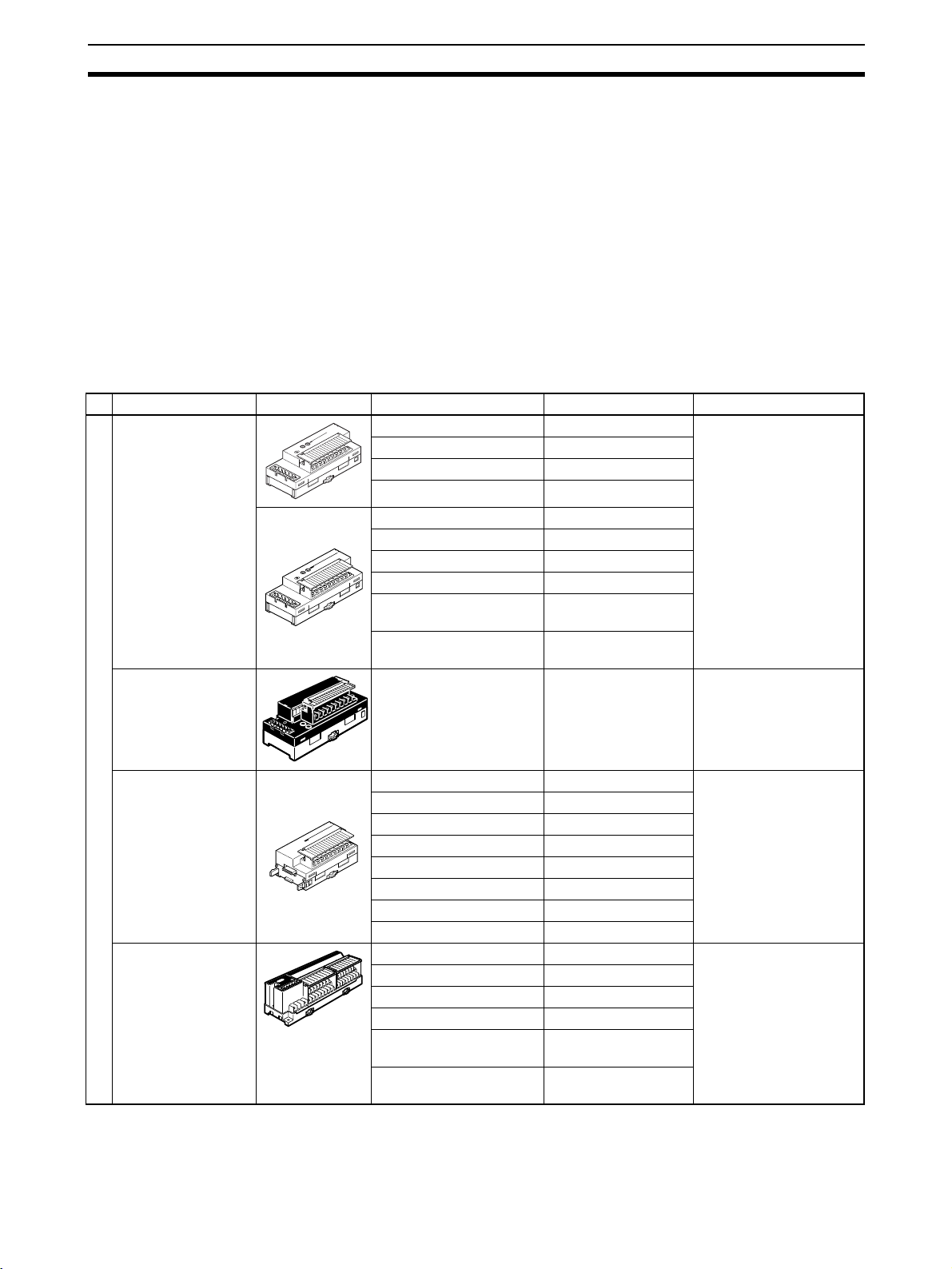
1-2-1 General-purpose Slaves
Name Appearance I/O points Model number Remarks
Remote I/O Terminals with Transistors
Remote I/O Terminal with Relay Outputs
8 input points (NPN) DRT2-ID08 Terminal block mounted/
8 input points (PNP) DRT2-ID08-1
8 output points (NPN) DRT2-OD08
8 output points (PNP) DRT2-OD08-1
16 input points (NPN) DRT2-ID16
16 input points (PNP) DRT2-ID16-1
16 output points (NPN) DRT2-OD16
16 output points (PNP) DRT2-OD16-1
8 input points/8 output
points (NPN)
8 input points/8 output
points (PNP)
16 output points DRT2-ROS16 Relay outputs
DRT2-MD16
DRT2-MD16-1
removed using screws.
Remote I/O Terminal Expansion Units
with Transistors
Remote I/O Terminals
Remote I/O Terminals with 3-tier Terminal Blocks and
Transistors
16 input points (NPN) XWT-ID16 Expansion Unit for
16 input points (PNP) XWT-ID16-1
16 output points (NPN) XWT-OD16
16 output points (PNP) XWT-OD16-1
8 input points (NPN) XWT-ID08
8 input points (PNP) XWT-ID08-1
8 output points (NPN) XWT-OD08
8 output points (PNP) XWT-OD08-1
16 input points (NPN) DRT2-ID16TA Wiring locations easy to
16 input points (PNP) DRT2-ID16TA-1
16 output points (NPN) DRT2-OD16TA
16 output points (PNP) DRT2-OD16TA-1
8 input points/8 output
points (NPN)
8 input points/8 output
points (PNP)
DRT2-MD16TA
DRT2-MD16TA-1
increasing inputs or outputs of the Basic Unit.
find (wiring to the same
terminal not required).
Cannot be expanded
with an Expansion Unit.
7
Page 29
DRT2 Slaves Section 1-2
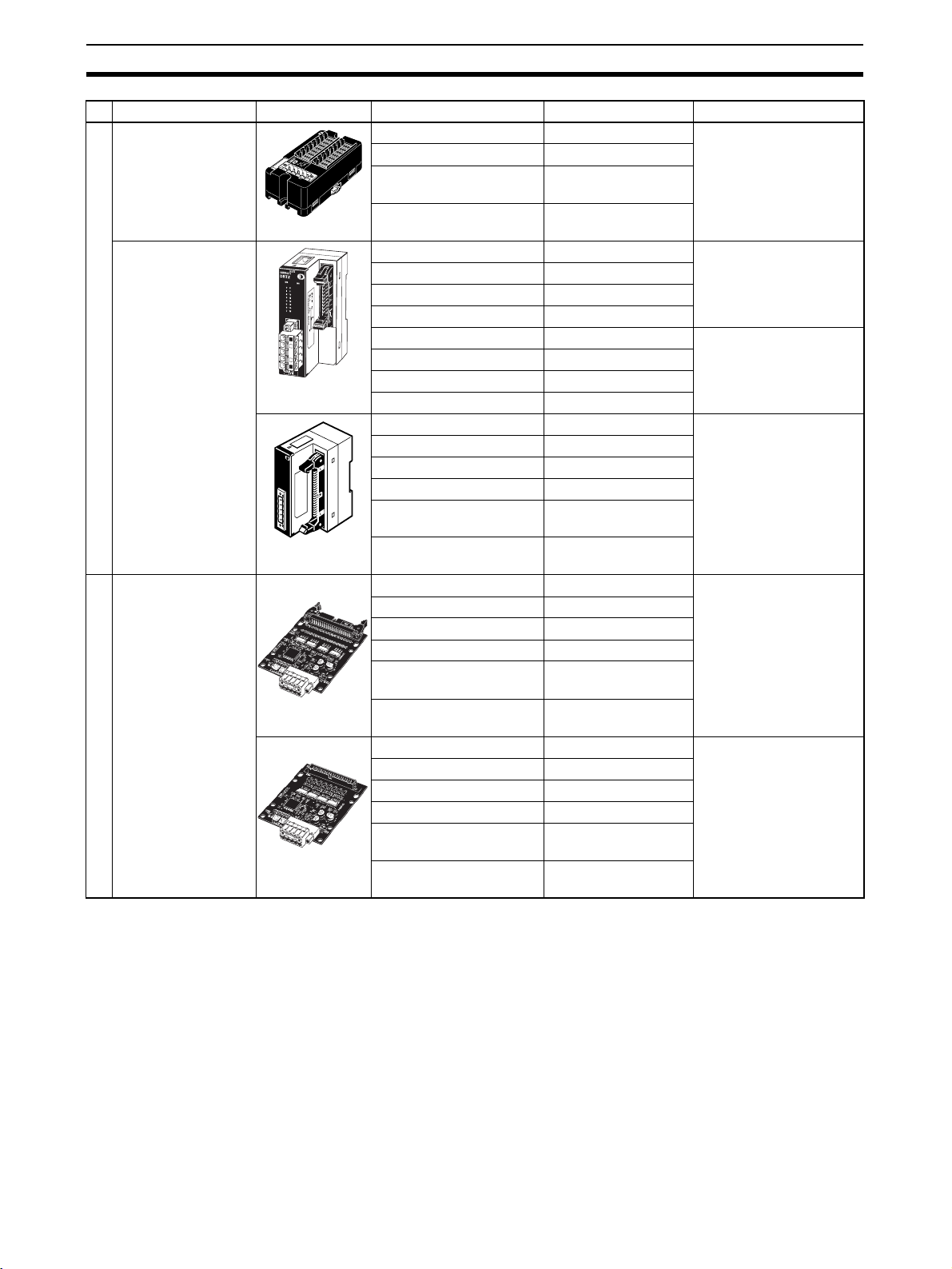
Name Appearance I/O points Model number Remarks
Sensor Connector
Terminals with Transistors
MIL Connector Terminals with Transistors
Connector Terminals
Board MIL Connector Terminals with
Transistors
Connector Terminals
16 input points (NPN) DRT2-ID16S Use industry standard
16 input points (PNP) DRT2-ID16S-1
8 input points/8 output
DRT2-MD16S
sensor connectors.
points (NPN)
8 input points/8 output
DRT2-MD16S-1
points (PNP)
16 input points (NPN) DRT2-ID16ML Connects to relay termi-
16 input points (PNP) DRT2-ID16ML-1
nal using MIL cable.
16 output points (NPN) DRT2-OD16ML
16 output points (PNP) DRT2-OD16ML-1
16 input points (NPN) DRT2-ID16MLX A connecting cable (10
16 input points (PNP) DRT2-ID16MXL-1
cm) is included.
16 output points (NPN) DRT2-OD16MLX
16 output points (PNP) DRT2-OD16MXL-1
32 input points (NPN) DRT2-ID32ML Connects to relay termi-
32 input points (PNP) DRT2-ID32ML-1
nal using MIL cable.
32 output points (NPN) DRT2-OD32ML
32 output points (PNP) DRT2-OD32ML-1
16 input points/16 output
DRT2-MD32ML
points (NPN)
16 input points/16 output
DRT2-MD32ML-1
points (PNP)
32 input points (NPN) DRT2-ID32B MIL connectors mounted
32 input points (PNP) DRT2-ID32B-1
parallel to board
32 output points (NPN) DRT2-OD32B
L
A
32 output points (PNP) DRT2-OD32B-1
N
I
M
n
R
o
V
i
t
4
E
a
2
T
r
o
:
E
p
r
E
T
o
C
O
C
R
M
U
E
n
o
O
R
r
S
m
O
16 input points/16 output
DRT2-MD32B
points (NPN)
16 input points/16 output
DRT2-MD32B-1
points (PNP)
32 input points (NPN) DRT2-ID32BV MIL connectors mounted
32 input points (PNP) DRT2-ID32BV-1
32 output points (NPN) DRT2-OD32BV
L
A
N
I
M
n
R
V
o
i
4
E
t
2
a
T
r
:
o
E
p
E
T
r
o
C
O
C
R
M
U
E
n
O
o
R
r
S
m
32 output points (PNP) DRT2-OD32BV-1
O
16 input points/16 output
DRT2-MD32BV
perpendicular to board
points (NPN)
16 input points/16 output
DRT2-MD32BV-1
points (PNP)
8
Page 30
DRT2 Slaves Section 1-2
Name Appearance I/O points Model number Remarks
Screw-less Clamp
Terminal with Transistors
Screw-less Clamp Terminals
16 input points (NPN) DRT2-ID16SL Without detection func-
16 input points (PNP) DRT2-ID16SL-1
16 output points (NPN) DRT2-OD16SL
16 output points (PNP) DRT2-OD16SL-1
16 input points (NPN) DRT2-ID16SLH With detection function
16 input points (PNP) DRT2-ID16SLH-1
16 output points (NPN) DRT2-OD16SLH
16 output points (PNP) DRT2-OD16SLH-1
32 input points (NPN) DRT2-ID32SL Without detection func-
32 input points (PNP) DRT2-ID32SL-1
32 output points (NPN) DRT2-OD32SL
32 output points (PNP) DRT2-OD32SL-1
16 input points/16 output
points (NPN)
16 input points/16 output
points (PNP)
32 input points (NPN) DRT2-ID32SLH With detection function
32 input points (PNP) DRT2-ID32SLH-1
32 output points (NPN) DRT2-OD32SLH
32 output points (PNP) DRT2-OD32SLH-1
16 input points/16 output
points (NPN)
16 input points/16 output
points (PNP)
DRT2-MD32SL
DRT2-MD32SL-1
DRT2-MD32SLH
DRT2-MD32SLH-1
tion
tion
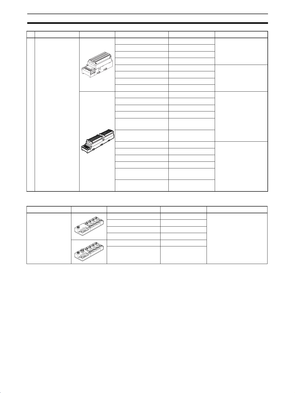
1-2-2 Environment-resistive Slaves
Name Appearance I/O points Model number Remarks
Environment-resistive Terminals,
Advanced Models
8 input points (NPN) DRT2-ID08C Waterproof, oil-proof, and
8 input points (PNP) DRT2-ID08C-1
16 input points (NPN) DRT2-HD16C
16 input points (PNP) DRT2-HD16C-1
8 output points (NPN) DRT2-OD08C
8 output points (PNP) DRT2-OD08C-1
spatter-proof construction
(IP67).
Equipped with detection
functions.
9
Page 31

DRT2 Slaves Section 1-2
Name Appearance I/O points Model number Remarks
Environment-resistive Terminals, Standard Models
4 input points (NPN) DRT2-ID04CL Waterproof, oil-proof, and
4 input points (PNP) DRT2-ID04CL-1
4 output points (NPN) DRT2-OD04CL
4 output points (PNP) DRT2-OD04CL-1
8 input points (NPN) DRT2-ID08CL
8 input points (PNP) DRT2-ID08CL-1
16 input points (NPN) DRT2-HD16CL
16 input points (PNP) DRT2-HD16CL-1
8 output points (NPN) DRT2-OD08CL
8 output points (PNP) DRT2-OD08CL-1
16 output points (NPN) DRT2-WD16CL
16 output points (PNP) DRT2-WD16CL-1
8 input points/8 output
points (NPN)
8 input points/8 output
points (PNP)
DRT2-MD16CL
DRT2-MD16CL-1
spatter-proof construction
(IP67).
Not equipped with detection
functions.
1-2-3 Analog Slaves
Name Appearance I/O points Model number Remarks
Analog Terminals 4 input points
(0 to 5 V, 1 to 5 V, 0 to
10 V, −10 to 10 V, 0 to
20 mA, 4 to 20 mA)
4 input points
(0 to 5 V, 1 to 5 V, 0 to
10 V, 0 to 20 mA, 4 to
20 mA)
DRT2-AD04 Terminal block mounted/
removed using screws.
The DRT2-AD04H is a High-
resolution Terminal (1/30,000
FS).
DRT2-AD04H
Temperature Input
Te r mi n al s
2 output points
(0 to 5 V, 1 to 5 V, 0 to
10 V, −10 to 10 V, 0 to
20 mA, 4 to 20 mA)
4 input points
(Switchable between R,
S, K1, K2, J1, J1, T, E, B,
N, L1, L2, U, W, and
PL2.)
4 input points
(Switchable between PT,
JPT, PT2, and JPT2.)
DRT2-DA02
DRT2-TS04T Thermocouple input
DRT2-TS04P Platinum resistance ther-
mometer input
10
Page 32

DRT2 Slaves Section 1-2
1-2-4 Smart Slave Feature Support
Yes: Supported.; No: Not supported.
Type General-purpose Slaves
Remote I/O Terminals
Standard Relay
Feature Input Output Mix Output Input Output Mix
Operation Time Monitor Yes (for inputs + outputs only) (See note
Contact Operation Counter Yes
Unit ON Time Monitor Yes
Total ON Time Monitor Yes
Naming Units Yes
Naming connected devices Yes
Network Power Voltage Monitor Yes
I/O Power Status Monitor Yes No Yes
Communications Error History Monitor Yes
Input filter Yes No Yes No Yes No Yes
Preventing malfunctions caused by inrush
current at startup
Sensor power short-circuit detection No
Sensor disconnected detection No
External load short-circuit detection No
External load disconnected detection No
Detachable terminal block construction Yes
Automatic baud rate detection Yes
Power supply wiring not required for Units Yes
Power supply wiring not required for input
devices
Expansion using Expansion Units Yes (See note 2.) No No No
Scaling No
User adjustment No
Last maintenance date Yes
Cumulative counter No
Moving average No
Setting the number of AD conversion points No
Peak/bottom hold No
Top / va ll e y ho l d No
Rate of change No
Comparator No
Communications error output No
1.)
Ye s N o Ye s N o Ye s N o Ye s
No Yes No No No
outputs
3-tier terminal block
Ye s
Note 1. The Operation Time Monitor cannot be used with the DRT2-@D08(-1).
2. The DRT2-@D08(-1) and DRT2-MD16(-1) cannot be expanded with an Ex-
pansion Unit.
3. The Contact Operation Counter and Total ON Time Monitor cannot be
used at the same time for the same contact.
11
Page 33

DRT2 Slaves Section 1-2
Yes: Supported.; No: Not supported.
Type General-purpose Slaves
Sensor Connector Terminals
Sensor connectors MIL connectors
(Board Terminals)
Feature Input Mix Input Output Mix
Operation Time Monitor No Yes Yes
Contact Operation Counter Yes
Unit ON Time Monitor Yes
Total ON Time Monitor Yes
Naming Units Yes
Naming connected devices Yes
Network Power Voltage Monitor Yes
I/O Power Status Monitor No Yes
Communications Error History Monitor Yes
Input filter Yes Yes No Yes
Preventing malfunctions caused by inrush current at
startup
Sensor power short-circuit detection Yes No
Sensor disconnected detection No
External load short-circuit detection No Yes No
External load disconnected detection No
Detachable terminal block construction No
Automatic baud rate detection Yes
Power supply wiring not required for Units Yes
Power supply wiring not required for input devices Yes No
Expansion using Expansion Units No
Scaling No
User adjustment No
Last maintenance date Yes
Cumulative counter No
Moving average No
Setting the number of AD conversion points No
Peak/bottom hold No
Top / va ll e y ho l d No
Rate of change No
Comparator No
Communications error output No
Ye s Ye s N o Ye s
12
Note The Contact Operation Counter and Total ON Time Monitor cannot be used at
the same time for the same contact.
Page 34

DRT2 Slaves Section 1-2
Yes: Supported.; No: Not supported.
Type General-purpose Slaves
Screw-less Clamp Terminals
DRT2-
@D16SLH (With
detection function)
Feature Input Output Input Output
Operation Time Monitor Yes
Contact Operation Counter Yes
Unit ON Time Monitor Yes
Total ON Time Monitor Yes
Naming Units Yes
Naming connected devices Yes
Network Power Voltage Monitor Yes
I/O Power Status Monitor Yes
Communications Error History Monitor Yes
Input filter Yes No Yes No
Preventing malfunctions caused by inrush current at
startup
Sensor power short-circuit detection Yes No No
Sensor disconnected detection Yes No No
External load short-circuit detection No Yes No
External load disconnected detection No Yes No
Detachable terminal block construction Yes
Automatic baud rate detection Yes
Power supply wiring not required for Units Yes
Power supply wiring not required for input devices No
Expansion using Expansion Units No
Scaling No
User adjustment No
Last maintenance date Yes
Cumulative counter No
Moving average No
Setting the number of AD conversion points No
Peak/bottom hold No
Top / va ll e y ho l d No
Rate of change No
Comparator No
Communications error output No
Ye s N o Ye s N o
DRT2-@D16SL (Without
detection function)
The Contact Operation Counter and Total ON Time Monitor cannot be used at
the same time for the same contact.
13
Page 35

DRT2 Slaves Section 1-2
Yes: Supported.; No: Not supported.
Type General-purpose Slaves
Screw-less Clamp Terminals
DRT2-@D32SLH (With detection
Feature Input Output Mix Input Output Mix
Operation Time Monitor Yes Yes
Contact Operation Counter Yes
Unit ON Time Monitor Yes
Total ON Time Monitor Yes
Naming Units Yes
Naming connected devices Yes
Network Power Voltage Monitor Yes
I/O Power Status Monitor Yes
Communications Error History Monitor Yes
Input filter Yes No Yes Yes No Yes
Preventing malfunctions caused by inrush
current at startup
Sensor power short-circuit detection Yes No Yes No
Sensor disconnected detection Yes No Yes No
External load short-circuit detection No
External load disconnected detection No Yes Yes No
Detachable terminal block construction Yes
Automatic baud rate detection Yes
Power supply wiring not required for Units Yes
Power supply wiring not required for input
devices
Expansion using Expansion Units No
Scaling No
User adjustment No
Last maintenance date Yes
Cumulative counter No
Moving average No
Setting the number of AD conversion points No
Peak/bottom hold No
Top / va ll e y ho l d No
Rate of change No
Comparator No
Communications error output No
Ye s N o Ye s Ye s N o Ye s
No
function)
DRT2-@D32SL (Without detection
function)
14
Note The Contact Operation Counter and Total ON Time Monitor cannot be used at
the same time for the same contact.
Page 36

DRT2 Slaves Section 1-2
Yes: Supported.; No: Not supported.
Type Environment-resistive Terminals
Advanced models Standard models
Feature Input Output Input Output Mix
Operation Time Monitor No No No (See note.) Yes
Contact Operation Counter Yes Yes Yes Yes Yes
Unit ON Time Monitor Yes Yes Yes Yes Yes
Total ON Time Monitor Yes Yes Yes Yes Yes
Naming Units Yes Yes Yes Yes Yes
Naming connected devices Yes Yes Yes Yes Yes
Network Power Voltage Monitor Yes Yes Yes Yes Yes
I/O Power Status Monitor No Yes Yes Yes Yes
Communications Error History Monitor Yes Yes Yes Yes Yes
Input filter Yes No Yes No Yes
Preventing malfunctions caused by inrush current at
startup
Sensor power short-circuit detection Yes No No No No
Sensor disconnected detection Yes No No No No
External load short-circuit detection No Yes No No No
External load disconnected detection No No No No No
Detachable terminal block construction No No No No No
Automatic baud rate detection Yes Yes Yes Yes Yes
Power supply wiring not required for Units Yes Yes Yes Yes Yes
Power supply wiring not required for input devices Yes No No No No
Expansion using Expansion Units No No No No No
Scaling NoNoNoNoNo
User adjustment No No No No No
Last maintenance date Yes Yes Yes Yes Yes
Cumulative counter NoNoNoNoNo
Moving average No No No No No
Setting the number of AD conversion points No No No No No
Peak/bottom hold NoNoNoNoNo
Top/valley hold No No No No No
Rate of change No No No No No
Comparator No No No No No
Communications error output No No No No No
Top/valley count function No No No No No
Temperature range timing function No No No No No
Input temperature variation detection function No No No No No
Ye s N o Ye s N o Ye s
Note (1) The Operation Time Monitor can be used with the DRT2-@D04CL(-1).
(2) The Contact Operation Counter and Total ON Time Monitor cannot be
used at the same time for the same contact.
15
Page 37

DRT2 Slaves Section 1-2
Yes: Supported.; No: Not supported.
Type Analog Slaves
Analog Terminals Temperature
DRT2-AD04 DRT2-AD04H DRT2-DA02
Feature Input Output Input
Operation Time Monitor No No No No
Contact Operation Counter No No No No
Unit ON Time Monitor Yes Yes Yes Yes
Total ON Time Monitor No No No No
Naming Units Yes Yes Yes Yes
Naming connected devices Yes Yes Yes Yes
Network Power Voltage Monitor Yes Yes Yes Yes
I/O Power Status Monitor No No No No
Communications Error History Monitor Yes Yes Yes Yes
Input filter No No No No
Preventing malfunctions caused by inrush current at startup No No No No
Sensor power short-circuit detection No No No No
Sensor disconnected detection No No No No
External load short-circuit detection No No No No
External load disconnected detection No No No No
Detachable terminal block construction Yes Yes Yes Yes
Automatic baud rate detection Yes Yes Yes Yes
Power supply wiring not required for Units Yes Yes Yes Yes
Power supply wiring not required for input devices No No No No
Expansion using Expansion Units No No No No
Scaling Yes Yes Yes Yes
User adjustment Yes Yes Yes Yes
Last maintenance date Yes Yes Yes Yes
Cumulative counter Yes Yes Yes Yes
Moving average Yes Yes No Yes
Setting the number of AD conversion points Yes No No No
Peak/bottom hold Yes Yes No Yes
Top/valley hold Yes Yes No Yes
Rate of change Yes Yes No Yes
Comparator Yes Yes No Yes
Communications error output No No Yes No
Top/valley count function No No No Yes
Temperature range timing function No No No Yes
Input temperature variation detection function No No No Yes
Input
Ter mina l
16
Note The Contact Operation Counter and Total ON Time Monitor cannot be used at
the same time for the same contact.
Page 38

DRT2 Slaves Section 1-2
1-2-5 Installing and Connecting Slaves
Slave type Communi-
cations
cables
General-purpose Slaves
Standard
rectangular
connector
Name Model Slave
Remote I/O
Te r m i n a ls
with Transistors
Remote I/O
Te r m i n a ls
with 3-tier Terminal Blocks
and Transistors
Remote I/O
Te r m i n a l
Expansion
Units with
Transistors
Remote I/O
Te r mi na l w it h
Relay Outputs
Sensor Connector Terminals with
Transistors
MIL Connector Terminals
with Transistors
DRT2-ID08 DIN Track M3 termi-
DRT2-ID08-1
DRT2-OD08
DRT2-OD08-1
DRT2-ID16
DRT2-ID16-1
DRT2-OD16
DRT2-OD16-1
DRT2-MD16
DRT2-MD16-1
DRT2-ID16TA DIN Track
DRT2-ID16TA-1
DRT2-OD16TA
DRT2-OD16TA-1
DRT2-MD16TA
DRT2-MD16TA-1
XWT-ID16 DIN Track See note.
XWT-ID16-1
XWT-OD16
XWT-OD16-1
XWT-ID08
XWT-ID08-1
XWT-OD08
XWT-OD08-1
DRT2-ROS16 Relay Shares
DRT2-ID16S DIN Track
DRT2-ID16S-1
DRT2-MD16S
DRT2-MD16S-1
DRT2-ID16ML DIN Track
DRT2-ID16ML-1
DRT2-OD16ML
DRT2-OD16ML-1
DRT2-ID16MLX
DRT2-ID16MLX-1
DRT2-OD16MLX
DRT2-OD16MLX-1
installation
or screws
or screws
or screws
with Mounting Bracket
I/O con-
nection
method
nal block
(detachable)
Industry
standard
connector
MIL connector
Internal
power sup-
ply
Shares
communications
power supply.
Shares
communications
power supply.
I/O power
supply
Requires
external
power supply.
communications
power supply. An
external
power supply is
required,
however, for
MD16S-1
outputs.
Requires
external
power supply.
17
Page 39

DRT2 Slaves Section 1-2
Slave type Communi-
General-purpose Slaves
cations
cables
Standard
rectangular
connector
Name Model Slave
MIL Connector Terminals
with Transistors
Board MIL
Connector
Te r m i n a ls
with Transistors
Screw-less
Clamp Terminal with Transistors
DRT2-ID32ML DIN Track
DRT2-ID32ML-1
DRT2-OD32ML
DRT2-OD32ML-1
DRT2-MD32ML
DRT2-MD32ML-1
DRT2-ID32B Screws
DRT2-ID32B-1
DRT2-OD32B
DRT2-OD32B-1
DRT2-MD32B
DRT2-MD32B-1
DRT2-ID32BV
DRT2-ID32BV-1
DRT2-OD32BV
DRT2-OD32BV-1
DRT2-MD32BV
DRT2-MD32BV-1
DRT2-ID16SL DIN Track Screw-less
DRT2-ID16SL-1
DRT2-OD16SL
DRT2-OD16SL-1
DRT2-ID32SL
DRT2-ID32SL-1
DRT2-OD32SL
DRT2-OD32SL-1
DRT2-MD32SL
DRT2MD32SL-1
DRT2-ID16SLH
DRT2-ID16SLH-1
DRT2-OD16SLH
DRT2-OD16SLH-1
DRT2-ID32SLH
DRT2-ID32SLH-1
DRT2-OD32SLH
DRT2-OD32SLH-1
DRT2-MD32SLH
DRT2-MD32SLH-1
installation
or screws
with Mounting Bracket
I/O con-
nection
method
MIL connector
clamp
Internal
power sup-
ply
Shares
communications
power supply.
I/O power
supply
Requires
external
power supply.
18
Note Use the following table to determine the I/O power supply for the Expansion
Unit.
Device combination I/O power supply to Expansion Unit
Basic Input Unit (IN) + Expansion Input
Unit (IN):
Example: DRT2-ID16+XWT-ID16
Basic Input Unit (IN) + Expansion Output
Unit (OUT):
Example: DRT2-ID16+XWT-OD16
Not required. (I/O power supply shared
with Basic Unit.)
Required. (I/O power supply required for
both Units.)
Page 40

DRT2 Slaves Section 1-2
Device combination I/O power supply to Expansion Unit
Basic Output Unit (OUT) + Expansion
Input Unit (IN):
Example: DRT2-OD16+XWT-ID16
Basic Output Unit (OUT) + Expansion
Output Unit (OUT):
Example: DRT2-OD16+XWT-OD16
Basic Output Unit (OUT) + Expansion
Output Unit (IN):
Example: DRT2-ROS16+XWT-ID16
Basic Output Unit (OUT) + Expansion
Output Unit (OUT):
Example: DRT2-ROS16+XWT-OD16
Required. (I/O power supply required for
both Units.)
Required. (I/O power supply required for
both Units.)
Required. (I/O power supply required for
Expansion Unit only.)
Required. (I/O power supply required for
Expansion Unit only)
Slave
type
Environmentresistive
Slaves
Analog
Slaves
Communi-
cations
cables
Round
communications
connector
Standard
rectangular
connector
Name Model Slave
Environment-resistive
Terminals
Analog Terminals
Te mp e r ature Input
Terminals
DRT2-ID08C Screw-
DRT2-ID08C-1
DRT2-HD16C
DRT2-HD16C-1
DRT2-OD08C Requires
DRT2-OD08C-1
DRT2-ID04CL
DRT2-ID04CL-1
DRT2-OD04CL
DRT2-OD04CL-1
DRT2-ID08CL
DRT2-ID08CL-1
DRT2-HD16CL
DRT2-HD16CL-1
DRT2-OD08CL
DRT2-OD08CL-1
DRT2-WD16CL
DRT2-WD16CL-1
DRT2-MD16CL
DRT2-MD16CL-1
DRT2-AD04 DIN Track M3 termi-
DRT2-AD04H
DRT2-DA02
DRT2-TS04T
DRT2-TS04P
mounted
installa-
tion
I/O con-
nection
method
Round
waterproof connector (for
XS2)
nal block
(detachable)
Connect-
ing
devices
Cable with
XS2 Connector +
Sensor
with Connector
Te r mi n al
block connection
Internal
power
supply
Shares
communications
power supply
I/O power
supply
Shares
communications
power supply
external
power supply.
Connected
with XS4@
connector.
Separate
power supply
required
for connected
devices,
such as
sensors
and actuators.
19
Page 41

DRT2 Slaves Section 1-2
20
Page 42

SECTION 2
Example System Startup
This section provides information on hardware aspects of Masters and Slaves connected to a DeviceNet Network to ensure
the proper operation of the system. Included are system configuration examples, basic procedures for wiring, details on
mounting and setting Master and Slave Units, procedures for connecting cables and power supplies, creating I/O tables,
creating and registering scan lists, and checking operation of the system.
2-1 Basic Procedures and Configuration Examples . . . . . . . . . . . . . . . . . . . . . . . 22
2-1-1 Basic Procedures. . . . . . . . . . . . . . . . . . . . . . . . . . . . . . . . . . . . . . . . 22
2-1-2 System Configuration Example . . . . . . . . . . . . . . . . . . . . . . . . . . . . 22
2-2 Preparations. . . . . . . . . . . . . . . . . . . . . . . . . . . . . . . . . . . . . . . . . . . . . . . . . . . 23
2-2-1 Selecting Units . . . . . . . . . . . . . . . . . . . . . . . . . . . . . . . . . . . . . . . . . 23
2-2-2 Wiring. . . . . . . . . . . . . . . . . . . . . . . . . . . . . . . . . . . . . . . . . . . . . . . . 23
2-2-3 Communications Power Supply . . . . . . . . . . . . . . . . . . . . . . . . . . . . 23
2-3 Setting and Wiring Hardware . . . . . . . . . . . . . . . . . . . . . . . . . . . . . . . . . . . . . 24
2-3-1 Mounting and Setting the Master Unit . . . . . . . . . . . . . . . . . . . . . . . 24
2-3-2 Mounting and Setting Slaves . . . . . . . . . . . . . . . . . . . . . . . . . . . . . . 25
2-3-3 Mounting Connecting Devices . . . . . . . . . . . . . . . . . . . . . . . . . . . . . 26
2-3-4 Connecting Cables . . . . . . . . . . . . . . . . . . . . . . . . . . . . . . . . . . . . . . 26
2-4 Starting Communications . . . . . . . . . . . . . . . . . . . . . . . . . . . . . . . . . . . . . . . . 27
2-4-1 Creating I/O Tables for the Master Unit. . . . . . . . . . . . . . . . . . . . . . 27
2-4-2 Starting the System. . . . . . . . . . . . . . . . . . . . . . . . . . . . . . . . . . . . . . 28
2-4-3 Creating and Registering Scan Lists. . . . . . . . . . . . . . . . . . . . . . . . . 28
2-5 Checking Operation . . . . . . . . . . . . . . . . . . . . . . . . . . . . . . . . . . . . . . . . . . . . 29
2-5-1 Indicator Status . . . . . . . . . . . . . . . . . . . . . . . . . . . . . . . . . . . . . . . . . 29
2-5-2 Reading and Writing Data . . . . . . . . . . . . . . . . . . . . . . . . . . . . . . . . 29
21
Page 43

Basic Procedures and Configuration Examples Section 2-1
2-1 Basic Procedures and Configuration Examples
The examples shown here provide the basic operating procedures for
DeviceNet.
2-1-1 Basic Procedures
The basic application procedures are as follows: For details on settings and
connections, refer to the operation manual for the Master Unit. For further
details on Slave Units, refer to SECTION 5 General-purpose Slaves and SEC-
TION 6 Environment-resistive Slaves.
Preparing the Units
1,2,3... 1. Select the appropriate Units. Refer to page 23.
2. Determine the appropriate wiring method. Refer to page 23.
3. Determine the appropriate method for supplying communications power.
Refer to page 23.
Setting and Wiring Hardware
1,2,3... 1. Separate and lay the cables.
2. Mount the Master Unit and specify the correct settings. Refer to page 24.
3. Mount the Slave Units and specify the correct settings. Refer to page 25.
4. Mount other devices to be connected to the Network. Refer to page 26.
5. Connect the cables. Refer to page 26.
6. Wire the I/O cables. Refer to page 26.
Starting Communications
1,2,3... 1. Create the I/O tables. Refer to page 27.
2. Start up the system. Refer to page 28.
3. Create and register the scan list. Refer to page 28.
Checking Operations
1,2,3... 1. Check the status of the indicators on the Unit. Refer to page 29.
2. Check that data is reading and writing properly. Refer to page 29.
Note The examples provided in this section show the minimum settings to operate
the system. If details on other settings for actual operation are required, refer
to the operation manual for the Master Unit. For further details on Slave Units,
refer to SECTION 5 General-purpose Slaves and SECTION 7 Analog Slaves.
2-1-2 System Configuration Example
The following diagram shows the operating procedure using a system configuration example.
The system configuration shown here uses Thin Cables.
The following diagram is simplified, so it does not include the separate I/O
power supply that must be provided to the Output Unit (or Expansion Output
Unit).
22
Page 44

Preparations Section 2-2
DRT2-ID16 Remote
I/O Terminal;
16 transistor inputs;
(Node 01)
DRT2-OD16 Remote
I/O Terminal;
16 transistor outputs;
(Node 02)
Terminating Resistor
2-2 Preparations
2-2-1 Selecting Units
Select the following Units as shown in 2-1-2 System Configuration Example.
Master Unit:CS1W-DRM21-V1
Slave Units:DRT2-ID16 + XWT-ID08
There is a complete line of OMRON Master Units and Slave Units available
CS1W-DRM21-V1
Master Unit (Node 63)
DCN1-3C T-branch
Ta p
DRT2-ID16 Remote I/O Terminal;
16 transistor inputs; XWT-ID08
Remote I/O Terminal Expansion Unit;
8 transistor inputs; (Node 03)
S82K-05024
24-V DC Power Supply (100 V AC, 50 W)
DCN1-1C T-branch
Ta p
DCN1-1C T-branch
Ta p
DRT2-OD16 Remote
I/O Terminal;
16 transistor outputs;
XWT-OD08 Remote
I/O Terminal
Expansion Unit;
8 transistor outputs;
(Node 04)
DRT2-OD16 + XWT-OD08
that are compatible with DeviceNet. Select Units that suit the
needs of the system.
2-2-2 Wiring
Either Thick Cables or Thin Cables can be used to wire a DeviceNet Network.
Flexible branching of cables is possible by using either T-branch Taps or multidrop connections.
Restrictions on the maximum network length and total branch line length
depend on the baud rate and type of cable used. For details on network configurations and specifications, refer to the DeviceNet Operation Manual
(W267).
2-2-3 Communications Power Supply
Each node (Master or Slave) must be supplied with a 24-V DC power supply
for proper DeviceNet communications.
The communications power, however, can be supplied by communications
cables and does not require separate wiring.
For systems that have a short maximum network length, power can be supplied to all nodes by using one communications power supply.
Various conditions, constraints, and measures affect how the communications
power is supplied. In the examples shown here, the power is supplied from
one communications power supply, and communications cables are connected using T-branch Taps.
For details on methods of supplying communications power, refer to the
DeviceNet Operation Manual (W267).
23
Page 45
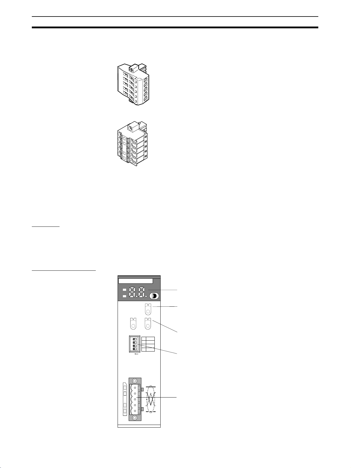
Setting and Wiring Hardware Section 2-3
9
8
7
6
5
4
3
2
1
0
9
8
7
6
5
4
3
2
1
0
F
E
D
C
B
A
9
8
7
6
5
4
3
2
1
0
Note Use the OMRON Connectors shown below when using Thick Cables and
multi-drop connections for wiring.
XW4B-05C4-TF-D (With set screws)
XW4G-05C4-TD-D (With set screws)
2-3 Setting and Wiring Hardware
Use the following procedures to mount, set, and wire the hardware.
2-3-1 Mounting and Setting the Master Unit
Settings The components, functions, and switch settings for the CS1W-DRM21,
CS1W-DRM21-V1 or CJ1W-DRM21 Master Unit mounted to a CS/CJ-series
PLC are shown as an example in the following diagram.
For information on switch settings, refer to the operation manual for the Master Unit.
CS1W-DRM21 (-V1)
DRM21
MS
NS
NODE
ADR
UNIT
No.
1234
ON
X10
CS
Indicators
Unit No. switch
This rotary switch sets the single-digit hexadecimal
unit number of the Master on the DeviceNet network.
1
0
X10
1
DR0
2
DR1
3
ESTP
HOLD
4
Node address switches
These rotary switches set the double-digit decimal
node address of the Unit.
DIP switch
These pins have the following functions:
Pins 1 and 2: Baud rate
Pins 3: Continue/stop remote I/O communications for
error (for Master functions)
Pin 4: Hold/clear I/O for communications error (for
Slave functions).
Communications connector
This connector is connected to the Network
communications cable. Communications power is
also supplied through this connector. An XW4B05C1-H1-D Parallel Connector with Screws is
provided as the node connector.
24
Page 46

Setting and Wiring Hardware Section 2-3
CJ1W-DRM21
DRM21
4
3
2
1
1
0
HOLD
ESTP
DR1
DR0
MS
NS
UNIT
5
4
6
3
7
2
8
1
9
0
A
NO.
F
B
E
C
D
3
3
4
4
2
2
5
5
1
6
6
0
7
7
9
9
8
8
ON
ON
1234
Indicators
Unit No. switch
This rotary switch sets the single-digit hexadecimal
unit number of the Master on the DeviceNet network.
Node address switches
These rotary switches set the double-digit decimal node address of the Unit.
DIP switches
These pins have the following functions:
Pins 1 and 2: Baud rate
Pins 3: Continue/stop remote I/O communications for error (for Master functions)
Pin 4: Hold/clear I/O for communications error (for Slave functions).
Communications connector
This connector is connected to the Network communications
cable. Communications power is also supplied through this
connector. An XW4B-05C1-H1-D Parallel Connector with
Screws is provided as the node connector.
Mounting The Master Unit is mounted to the Backplane of the PLC in the same way as
other Units are normally mounted. CJ-series Master Units have no Backplane,
so connect the Units together by joining the connectors. For details on mounting Master Units to PLCs, and PLCs to control panels, refer to the applicable
PLC Operation Manual.
2-3-2 Mounting and Setting Slaves
Settings The following example shows Slave settings. For details on how to set Slaves,
refer to SECTION 5 General-purpose Slaves to SECTION 7 Analog Slaves.
• DRT2-ID16 Remote I/O Terminals (transistor inputs)
Node address: 01
• DRT2-OD16 Remote I/O Terminals (transistor outputs)
Node address: 02
• DRT2-ID16 Remote I/O Terminals (transistor inputs)
XWT-ID08 Remote I/O Terminal Expansion Unit
Node address: 03
• DRT2-OD16 Remote I/O Terminals (transistor outputs)
XWT-OD08 Remote I/O Terminal Expansion Unit
Node address: 04
Mounting Remote I/O Terminals are mounted by fixing to a DIN Track, as shown in the
following example.
Secure the bottom of the Slave Unit to a 35-mm DIN Track, or secure the
Slave Unit to the track between two End Plates.
Mounting Example The following diagram shows all Units except the PLC node mounted to DIN
Tr ac k s.
Master
Remote I/O
Terminal (Input)
Remote I/O
Terminal (Output)
0
25
Page 47

Setting and Wiring Hardware Section 2-3
2-3-3 Mounting Connecting Devices
The following connecting devices require being mounted:
• T-branch Taps: Secure to the control panel with screws, or mount to a DIN
Tr ac k .
• Terminal-block Terminating Resistors: Secure to the control panel with
screws.
2-3-4 Connecting Cables
Connecting
Communications
Cables
Connect the Master Unit and T-branch Taps, T-branch Taps and T-branch
Taps, and T-branch Taps and Slaves using Thin DeviceNet Communications
Cables, as shown in the following diagram.
When a Terminating Resistor is required, connect it to the
final T-branch Tap in the Network. The T-branch Tap must
be no further than 6 m from the final node.
24-V DC power
supply
Remote I/O
Terminal
T-branch
Ta p
T-branch
Ta p
Remote I/O
Terminal
Remote I/O
Terminal
Remote I/O
Terminal
Terminating
Resistor
CS Rack
T-branch
Ta p
If a Terminal-block Terminating Resistor is required, connect it to
the end of an extension cable (1 m max.) that is connected to the
final node.
Use the following procedure to connect the cables. Refer to 5-2 Connecting
Communications Cables to General-purpose Slaves for details.
1,2,3... 1. Prepare the communications cables and attach the connectors to the ca-
bles.
2. Connect the communications cable connectors to the node connectors on
the Master Unit, T-branch Taps, and Slaves.
Wiring the I/O Power
Supply
If required, an I/O power supply for I/O devices is connected to the Remote
I/O Terminals. Connect M3 crimp terminals to the power lines and then connect them to the terminal block.
Wiring I/O Wire the I/O to the Remote I/O Terminals.
Connect M3 crimp terminals to the signal lines and then connect them to the
terminal block.
26
Page 48

Starting Communications Section 2-4
2-4 Starting Communications
After setting and wiring the hardware, turn ON the communications power
supply, the internal power supply of each node, and the I/O power supply, and
then start communications using the following procedure.
2-4-1 Creating I/O Tables for the Master Unit
I/O tables must be created in the CPU Unit to distinguish between the different
Slaves mounted to the PLC. Turn ON the PLC to which the Master Unit is
mounted, connect the Peripheral Devices to the PLC, and create the I/O
tables. After the I/O tables have been created, turn OFF the power to the PLC.
The following example shows the procedure for creating I/O tables using a
Programming Console. For details on creating I/O tables, refer to the operation manual for the Peripheral Device being used.
Turn ON the power to the
Master Unit
PROGRAM
Switch the CPU Unit of the
Master Unit to PROGRAM
mode.
<PROGRAM>
PASSWORD!
CLR
000000 CT00
FUN
00000IOTBL ?
?-?U=
CHG
00000IOTBL WRIT
????
9 7 1 3
00000IOTBL WRIT
9713
WRITE
00000IOTBL WRIT
OK
0
MONTR
SHIFT
CLR
CLR
CH
*DM
WRITE
27
Page 49

Starting Communications Section 2-4
2-4-2 Starting the System
Turn ON the communications power supply and the power to other nodes in
the following order.
1,2,3... 1. Turn ON the communications power supply.
2. Turn ON the power to each Slave.
3. Turn ON the power to the Master Unit.
Note The power supplies listed above can all be turned ON simultaneously. The
external I/O power supply can be turned ON at any time.
2-4-3 Creating and Registering Scan Lists
Scan lists are lists that register the information that is transferred between
Master Units and Slaves. The Master Unit compares the scan list with the status of the Slave currently being communicated with, so communications with
the Slave are always being checked.
For details on scan lists and remote I/O communications, refer to the operation manual for the Master Unit.
Note When a scan list is disabled, communications are possible with all Slaves on
the DeviceNet Network with fixed allocations. Without scan lists, however, the
Master Unit cannot check if there is an error in a Slave.
For normal operations, always enable the scan lists.
Precautions
User I/O Allocations The user can allocate any words for Slave I/O for the DeviceNet I/O Areas (IN
Area, OUT Area) in the Master Unit.
When user allocations are used, scan lists must be created with a DeviceNet
Configurator and registered in the Master Unit. The scan list is enabled as
soon as it is registered, and remote I/O communications start according to the
scan list.
For details, refer to the DeviceNet Operation Manual (W267) and the
DeviceNet Configurator Operation Manual (W328).
Fixed I/O Allocations Slave I/O is allocated in the DeviceNet I/O area (IN Area, OUT Area) in the
Master Unit in the same order as the Slave node addresses.
When fixed allocations are used, the scan lists are automatically created and
registered using the Master Unit's software switches. The scan list is enabled
as soon as it is registered, and remote I/O communications start according to
the scan list. When scan list is enabled, the mode is called the scan listenabled mode.
The registered scan lists can be cleared using the software switches. When
scan lists are cleared (disabled), the mode is called the scan list-disabled
mode.
Creating and
Registering Fixed
Allocation Scan Lists
The method of creating and registering scan lists for fixed allocation using
Programming Console and a CS/CJ-series Master Unit is explained here. For
details on operating Peripheral Devices, refer to the operation manual for the
Peripheral Device being used with the PLC. For details on creating scan lists,
refer to the operation manual for the Master Unit.
28
Page 50

Checking Operation Section 2-5
Creating and Registering
Scan Lists
Use the following procedure to create, register, and enable the scan lists.
In the following example, n = 1500 + (25 × unit number).
Clearing and Creating Scan Lists
Switch the operating mode switch to PROGRAM mode.
Enable the Master Unit functions. Set the Master Unit function enable switch
(bit 06 of word n) from OFF to ON.
Clear the scan lists. Set the scan list clear switch (bit 01 of word n) from OFF
to ON.
Select the fixed allocation areas 1 to 3. Set the Master Unit's setting switch for
fixed allocation areas 1 to 3 (bit 00 of word n) from OFF to ON.
Enable the scan lists. Set the scan list enable switch (bit 00 of word n) from
OFF to ON.
Switch the operating mode switch to RUN or MONITOR mode.
Checking the Normal Slave Table
Monitor the normal Slave table and check that the corresponding bits are ON.
In the normal Slave table, the corresponding bits will turn ON for the nodes
that are communicating normally.
2-5 Checking Operation
Use the procedures provided here to check that I/O communications are operating normally.
2-5-1 Indicator Status
I/O communications are operating normally if the MS and NS indicators for all
nodes are lit green, and the 7-segment indicator on the front panel of the Master Unit is displaying the node address of the Master Unit as shown in the following diagram (when the Master Unit's node address is 00), and the scan list
is enabled.
Master Unit 7-segment
Display
OFF: Operating as a Slave.
OFF: Scan list enabled.
Master Unit node address 00
Display switches between error code and error
node address when an error occurs.
2-5-2 Reading and Writing Data
Connect the Peripheral Device for the PLC to the Master Unit, write the Master Unit's OUT Area and read the IN Area, and check that the data are the
same in the Slaves.
Refer to the operation manual for the Master Unit for details on OUT Area and
IN Area addresses and how to allocate Slave I/O.
29
Page 51

Checking Operation Section 2-5
I/O between Remote I/O
Termina ls
Create ladder programs in the PLC of the Master Unit, and check that when
the switch on the DRT2-ID16 Input Terminal turns ON, the indicator on the
DRT2-OD16 Output Terminal is ON.
Master Unit
DRT2-ID16 Remote
I/O Terminal
(Node 01)
DRT2-OD16
Remote I/O Terminal
(Node 02)
330100 320200
Switch 1
(bit 00)
Indicator
(bit 00)
Precautions In the system configuration examples in this section, Slave I/O is allocated in
the Master Unit's CIO Area for fixed remote I/O communications as shown in
the following diagram.
OUT area IN area
CIO 3200
CIO 3201
CIO 3203
CIO 3204
CIO 3205
CIO 3206
CIO 3207
CIO 3208
CIO 3209
Not used
Not used
DRT2-OD16CIO 3202
Not used
DRT2-OD16
Not used
XWT-OD08
CIO 3300
CIO 3302
CIO 3303
CIO 3304
CIO 3305
CIO 3306
CIO 3307
CIO 3308
CIO 3309
DRT2-ID16CIO 3301
DRT2-ID16
Not used
Not used
Not used
XWT-ID08
Not used
30
Page 52

SECTION 3
Common Slave Specifications
This section provides specifications and indicator displays that are common to all Slaves. The allocation of remote I/O
memory for Smart Slaves is also described here.
3-1 Common Slave Specifications . . . . . . . . . . . . . . . . . . . . . . . . . . . . . . . . . . . . 32
3-1-1 Communications Specifications . . . . . . . . . . . . . . . . . . . . . . . . . . . . 32
3-1-2 MS and NS Indicators. . . . . . . . . . . . . . . . . . . . . . . . . . . . . . . . . . . . 32
3-2 DeviceNet Remote I/O Communications . . . . . . . . . . . . . . . . . . . . . . . . . . . . 34
3-2-1 Overview of Remote I/O Allocations for Smart Slaves . . . . . . . . . . 34
3-2-2 I/O Allocations for Smart Slaves . . . . . . . . . . . . . . . . . . . . . . . . . . . 36
3-2-3 I/O Allocation with the Configurator (Ver. 2.@ or Later). . . . . . . . . 42
31
Page 53

Common Slave Specifications Section 3-1
3-1 Common Slave Specifications
3-1-1 Communications Specifications
Item Specifications
Communications protocol DeviceNet
Supported connections
(communications)
Connection forms Combination of multi-drop and T-branch connections (for trunk or branch lines)
Baud rate 500 kbps, 250 kbps, or 125 kbps
Communications media Special 5-wire cables (2 signal lines, 2 power lines, 1 shield line)
Communications distances Baud rate Network length Branch line length Total branch line
Communications power
supply
Max. number of nodes 64 nodes (including Configurator when used)
Max. number of Slaves 63 Slaves
Communications cycle time Without Configurator: 16 Input Slaves (16-pt)
Error control CRC error check
Remote I/O: Master-Slave connection
(Poll/Bit-Strobe/COS/Cyclic)
Conform to DeviceNet specifications.
length
500 kbps 100 m max (100 m max) 6 m max. 39 m max.
250 kbps 250 m max (100 m max) 6 m max. 78 m max.
125 kbps 500 m max (100 m max) 6 m max. 156 m max.
Values in parentheses indicate the length when Thin Cables are used.
11 to 25 V DC
16 Output Slaves (16-pt)
Baud rate of 500 kbps:
Cycle time: 9.3 ms
3-1-2 MS and NS Indicators
This section describes the meanings of MS and NS indicators for the Slave
Units.
The MS (Module Status) indicator displays the status of a node on the network.
The NS (Network Status) indicator displays the status of the entire network.
The MS and NS indicators can be green or red and they can be ON, flashing,
or OFF.
Indicator Color Status Definition Meaning
MS Green Lit Device operational Normal operating status.
Red Lit Unrecoverable fault Unit hardware error (watchdog timer error).
Flashing Minor fault Switch settings incorrect, etc.
--- Not lit No power Power is not being supplied to the Slave Unit.
Waiting for initial processing to start.
The Unit is being reset.
32
Page 54

Common Slave Specifications Section 3-1
Indicator Color Status Definition Meaning
NS Green Lit Online/connected Network is operating normally (communications
Flashing Online/ not connected Network is operating normally, but communica-
Red Lit Critical link failure Communications error (Unit has detected that
Flashing Connection time-out Communications time-out.
--- Not lit Not powered/Not online Checking for node address duplication at the
established).
tions have not been established.
network communications are not possible).
Node address duplication
Bus Off error
Master.
Switch settings are incorrect.
Power supply is OFF.
33
Page 55

DeviceNet Remote I/O Communications Section 3-2
3-2 DeviceNet Remote I/O Communications
This section describes how DRT2-slave data can be allocated for remote I/O
communications with the Master Unit.
3-2-1 Overview of Remote I/O Allocations for Smart Slaves
Unlike the DRT1-series Slaves, the DRT2-series Smart Slaves store data
internally. When necessary, the user can specify which data is allocated for
remote I/O communications with the Master Unit. (Allocation is not required,
however, for the default I/O data.)
Master
Specify which
data is allocated
where.
Smart Slave
A
Data is
B
stored
internally.
C
• Data can be specified in either of the two ways described below.
• Select a data pattern (fixed combination) using the Slave’s default
connection path setting.
Master
A
B
Smart Slave
Specified
data pattern
allocated.
A
B
A
Select from
predetermined
C
data patterns.
B
C
• Select individual data as desired
using the Master’s connection setting.
Master
A
C
Smart Slave
Specified data
allocated.
A
B
C
Select the
required
data.
Smart Slave I/O
Allocation Methods
34
Either fixed allocation or user allocation is
possible.
Only possible with user allocation and if
the Master Unit is a CS/CJ-series
DeviceNet Unit.
Smart Slave data can be allocated to the Master Unit for remote I/O communications in any of the ways described below.
Page 56

DeviceNet Remote I/O Communications Section 3-2
Fixed Allocation
Type Allocating default I/O data Allocating selected I/O data (patterns)
Description I/O data is allocated to fixed addresses in the
Master Unit in order of node address.
Method Configurator not used. Configurator used to select I/O data (pattern).
Configuration
Master CPU Unit
Allocation
I/O memory
A
B
Smart Slave
I/O data
Node
address
order
A
B
Selected I/O data (pattern) is allocated to fixed
addresses in the Master Unit.
Select I/O from the
Configurator’s Edit
Device Parameters
Window for t he Slave.
Master CPU Unit
Master CPU Unit
I/O memory
Node
A
address
C
order
Smart Slave
I/O data (patterns)
A
(Default)
B
Allocation
A
C
D
E
Select I/O data
pattern (fixed
combination).
Setting method
None In the Slave’s Edit Device Parameters Window,
with Configurator
User Allocation
Type Allocating default I/O data Allocating selected I/O data (patterns)
Description I/O data is allocated to user-defined addresses
Method Configurator used to allocate user-defined
Configuration
in the Master Unit.
addresses.
Master CPU Unit
I/O memory
A
Allocated to
B
user-defined
addresses.
Smart Slave
I/O data
A
Allocation
B
Allocate I/O to userdefined addresses
using the Configurator.
select the data in the Slave from the pull-down
menu for the Slave’s default connection path, and
execute download.
Selected I/O data (pattern) is allocated to userdefined addresses in the Master Unit.
1. Configurator used to select I/O data (pattern).
2. Selected data allocated to user-defined memory addresses.
Select I/O from the
Configurator’s Edit Device
Parameters Window for
Master CPU Unit
I/O memory
A
C
Smart Slave
I/O data (patterns)
the Slave, and allocate to
user-defined addresses.
2. Allocate to
user-defined
addresses.
A
(Default)
B
A
C
D
E
1. Select I/O data
pattern (fixed
combination).
Setting method
with Configurator
In the Master’s Edit Device Parameters Window, allocate Slave I/O.
1. In the Slave’s Edit Device Parameters Window,
select the data in the Slave from pull-down
menu for the Slave’s default connection path,
and execute download.
2. In the Master’s Edit Device Parameters Window, allocate Slave I/O.
35
Page 57

DeviceNet Remote I/O Communications Section 3-2
Type Selecting I/O data and allocating to user-defined addresses
Description Select up to two types of I/O data, and allocate to user-defined addresses in the Master Unit.
Method 1. Select up to two types of I/O data using the Configurator.
2. Allocate the selected I/O data to user-defined addresses in the Master Unit.
Configuration
Allocation
Master CPU Unit
I/O memory
A
Allocate to userdefined addresses.
E
Allocate to userdefined addresses.
With the Configurator, for
each connection, select
data and allocate to
user-defined addresses.
Setting method
with Configurator
1. Specify two connections.
2. Specify each
connection path.
Note: Up to two connections can be specified from
CS/CJ-series Master Units.
1. In the Master’s Edit Device Parameters Window, select the Smart Slave to be set, and specify the
connection in the Advanced Setting Window. Select the I/O data (pattern) in the connection path
Smart Slave
Data
A
B
C
D
E
setting.
2. In the Master’s Edit Device Parameters Window, allocate Slave I/O.
Note The above method can be used only if the Master Unit is a CS/CJ-series
DeviceNet Unit. When using a CVM1/CV-series DeviceNet Master Unit, a
C200HX/HG/HE/HS DeviceNet Master Unit, or another company’s Master
Unit, select the I/O data from the pull-down menu for the default connection
path in the Slave’s Edit Device Parameters Window.
3-2-2 I/O Allocations for Smart Slaves
General-purpose
Slaves and
Environment-resistive
Slaves
1,2,3... 1. Allocating only real I/O data (default)
36
DRT2-slave data can be allocated for remote I/O communications with the
Master Unit using any of the following methods.
2. Allocating real I/O data and Generic Status Flags together
3. Allocating real I/O data and Generic Status Flags independently
Method 2 can be performed by selecting the I/O data and flags from the
pull-down menu for the Slave’s default connection path using the Configurator.
Method 3 can be performed by allocating real I/O data and Generic Status
Flags independently in the Master’s connection path using the Configurator. (This method can be used only with CS/CJ-series Master Units.)
Page 58

DeviceNet Remote I/O Communications Section 3-2
■ Example of Allocation Using Method 2
Master CPU Unit
15 8 7 0
IN Area
DRT2-series Slave
Status
Status: 8 points
Node address 1
Real inputs: 16 points
15
14 13
Real inputs (e.g., 16 points)
0 1
The Generic Status Flags are as follows:
Bit Contents
0 Basic Unit's I/O Power Status Flag
0: I/O power supply ON
1: I/O power supply OFF
1 Expansion Unit's I/O Power Status Flag
0: I/O power supply ON
1: I/O power supply OFF
2 Network Power Voltage Drops Flag
0: Normal (Higher than set monitor value)
1: Error (Same as or lower than set monitor value)
3 Unit Maintenance Flag
0: Within range (Lower than set monitor value)
1: Out of range (Same as or higher than set monitor value)
4 Sensor Disconnected Flag (Screw-less Clamp Input and I/O Terminals, and
Environment-resistive Input Terminals only) or External Load Disconnected
Flag (Screw-less Clamp Output and I/O Terminals only)
0: Connected (all inputs connected)
1: Disconnected (at least one input is not connected)
Cumulative Counter Flag (Analog Input Terminals and Temperature Input
Terminals)
0: Normal
1: Error (monitoring set value exceeded)
5 Short-circuited Flag (Sensor Connector Terminals, Screw-less Clamp Input
and I/O Terminals, and Environment-resistive Input Terminals only), or
External Load Short-circuited Flag (Environment-resistive Output Terminals, Sensor Connector Terminals, I/O Units only)
0: Normal I/O (all I/O points normal)
1: Short-circuited I/O (one or more I/O point short-circuited)
Unit Error Flag (Analog Input Terminals and Temperature Input Terminals)
0: Normal
1: Error (Data conversion stopped during to error in Unit.)
See note 1.
37
Page 59

DeviceNet Remote I/O Communications Section 3-2
Bit Contents
6 Operation Time Over Flag
0: Within range (all output-to-input sets are
lower than set monitor value)
1: Out of range (one or more output-toinput set is same as or higher than set
monitor value)
7 Connected Component Maintenance Flag
0: Within range (all I/O points are lower than set monitor value)
1: Out of range (one or more I/O point is same as or higher than set monitor
value)
Cold Junction Compensator Off-wire Flag
0: Normal
1: Error (off-wire connected)
Note 1. Bits 00 and 01 (I/O power supply voltage statuses 1 and 2, respectively)
indicate the status of the system power supply, as follows
Bit Name System configuration
0Basic Unit's
I/O Power
Status Flag
1 Expansion
Unit's I/O
Power St atus Flag
Basic Unit
only
(Expansion
Unit not
used)
Basic Unit I/O power supply Basic Unit I/O
--- (Not used.) Expansion
Basic Unit
Input
Terminal and
Expansion
Unit Input
Ter mina l
See note 2.
Basic Unit
Output or
Input
Terminal and
Expansion
Unit Output
Termina l
power supply
Unit output
power supply
:
Basic Unit
Output
Terminal and
Expansion
Unit Input
Ter mina l
Basic Unit output power
supply
Expansion
Unit input
power supply
Allocating Only Real I/O
Data (Default)
2. The Operation Time Over Flag functions only for Slaves with both inputs
and outputs. It does not function for Slaves with only IN or OUT areas.
Example 1: Using 16 inputs.
IN Area
15 0
Address header Allocated 16 inputs.
Example 2: Using 16 outputs.
OUT Area
15 0
Address header Allocated 16 outputs.
Example 3: Using 32 inputs.
IN Area
15 0
Address header Allocated 32 inputs.
Address header + 1
38
Page 60

DeviceNet Remote I/O Communications Section 3-2
Example 4: Using 16 inputs and 8 inputs (Expansion Unit).
IN Area
15 0
Address header Allocated 16 inputs.
Address header + 1
Example 5: Using 16 outputs and 8 inputs (Expansion Unit).
15 0
Address header Allocated 16 outputs.
Address header
Allocated 8 inputs.
OUT Area
IN Area
70
Allocated 8 inputs.
Allocating Real I/O Data
and Generic Status Flags
Toget h e r
The Generic Status Flags are for providing notification of the status of the
Smart Slave to the host. They are allocated to the Master Unit’s IN Area and
consist of 8 bits.
Example 1: Using 16 inputs.
IN Area
15 0
Address header Allocated 16 inputs.
Address header + 1
Generic Status Flags
Example 2: Using 16 outputs.
OUT Area
15 0
Address header Allocated 16 outputs.
IN Area
70
Address header
Generic Status Flags
Example 3: Using 32 inputs.
IN Area
15 0
Address header Allocated 32 inputs.
Address header + 1
Address header + 2
Generic Status Flags
Example 4: Using 16 inputs and 8 inputs (Expansion Unit).
IN Area
15 0
Address header Allocated 16 inputs.
Address header + 1
Generic Status Flags
Allocated 8 inputs.
Example 5: Using 16 outputs and 8 inputs (Expansion Unit).
OUT Area
15 0
Address header Allocated 16 outputs.
39
Page 61

DeviceNet Remote I/O Communications Section 3-2
IN Area
15 8 7 0
Address header
Generic Status Flags
Allocated 8 inputs.
Allocating Real I/O Data
and Generic Status Flags
Individually
Instead of allocating real I/O and Generic Status Flags together, they can be
allocated individually. This is only possible, however, if the Master Unit is a
CS/CJ-series DeviceNet Unit and the Configurator is used.
15 0
I/O Area
I/O Area
:
Status Area
Status Area
Node address 00
Node address 01
Node address 00
Node address 01
Analog Slaves Data that is allocated for remote I/O communications can be selected using
any of the following methods.
1,2,3... 1. Allocating only analog values (default I/O data)
2. Allocating a fixed I/O data pattern
3. Allocating user-defined I/O data
With methods 2 and 3, the Configurator is used to specify the I/O data that is
to be allocated. An outline of the methods used is given below.
Allocating Fixed I/O Data
Patterns
Allocating User-defined
I/O Data
There are eleven fixed I/O data patterns. The Configurator is used to select
the desired I/O data pattern from the pull-down menu for the Slave's default
connection path in the Edit Device Parameters Window.
Using the Configurator, the desired combination of I/O data can be allocated
for the Master Unit connection. The desired connection is selected from the
Master's Edit Device Parameters Window. Up to two of the eleven I/O data
patterns can be selected for the connection paths of the connection.
Note If analog data is allocated to a COS connection, a frame will be sent to the
host each analog conversion cycle. This will cause frames to be sent frequently, increasing network traffic and possibly affecting the communications
cycle time.
The Generic Status Flags that are allocated are listed in the following tables.
Analog Terminals
Bit Name Description
0 --- Not supported (always 0).
1 --- Not supported (always 0).
2 Network Voltage
Monitor Flag
3 Unit Conduction
Time Monitor Flag
4 Cumulative Counter
Flag
5 Unit Error Flag Turns ON when analog conversion stops due to an
6 --- Not supported (always 0).
7 --- Not supported (always 0).
ON as long as the network power supply remains
below the monitoring set value.
Turns ON when the time that power is supplied to the
Unit exceeds the monitoring set value.
Turns ON when any of the cumulative values
exceeds the monitoring set value.
error in the Unit.
40
Page 62

DeviceNet Remote I/O Communications Section 3-2
Temperature Input Terminals
Bit Name Description
0 --- Not supported (always 0).
1 --- Not supported (always 0).
2 Network Voltage
Monitor Flag
3 Unit Conduction
Time Monitor Flag
4 Temperature Data
Cumulative Counter
Flag
5 Unit Error Flag Turns ON when temperature conversion stops due to
6 --- Not supported (always 0).
7 Cold Junction Com-
pensator Off-wire
Flag
The data (patterns) listed in the following tables can be allocated. Ether the
default setting can be used or allocations can be made in the master using the
Configurator
■ I/O Data for Analog Input Terminals (DRT2-AD04/AD04H)
Analog Data 1 (8 input bytes) (default)
Analog Data 2 (8 input bytes)
Generic Status Flags (1 input byte)
Top/Valley Detection Timing Flags (2 input bytes)
Analog Status Flags (4 input bytes)
Analog Data 1 + Analog Data 2 (16 input bytes)
Top/Valley Detection Timing Flags + Generic Status Flags (3 input bytes)
Analog Status Flags + Generic Status Flags (5 input bytes)
Analog Data 1 + Top/Valley Detection Timing Flags (10 input bytes)
Analog Data 1 + Top/Valley Detection Timing Flags + Generic Status Flags (11 input
bytes)
Hold Flags (1 output byte)
ON as long as the network power supply remains
below the monitoring set value.
Turns ON when the time that power is supplied to the
Unit exceeds the monitoring set value.
Turns ON when any of the cumulative values
exceeds the monitoring set value.
an error in the Unit.
Turns ON when the cold junction compensator is disconnected. (DRT2-TS04T only)
Data (patterns)
■ I/O Data for Temperature Input Terminals (DRT2-TS4T/TS4P)
Data (patterns)
Temperature Data 1 (8 input bytes) (default)
Temperature Data 1, 1/100 Display (16 input bytes)
Temperature Data 2 (8 input bytes) (default)
Temperature Data 2, 1/100 Display (16 input bytes)
Generic Status Flags (1 input byte)
Top/Valley Detection Timing Flags (2 input bytes)
Analog Status Flags (4 input bytes)
Temperature Data 1 + Temperature Data 2 (16 input bytes)
Temperature Data 1 + Temperature Data 2, 1/100 Display (32 input bytes)
Top/Valley Detection Timing Flags + Generic Status Flags (3 input bytes)
Analog Status Flags + Generic Status Flags (5 input bytes)
Temperature Data 1 + Top/Valley Detection Timing Flags (10 input bytes)
Temperature Data 1, 1/100 Display + Top/Valley Detection Timing Flags (18 input
bytes)
41
Page 63

DeviceNet Remote I/O Communications Section 3-2
Data (patterns)
Temperature Data 1 + Top/Valley Detection Timing Flags + Generic Status Flags (11
input bytes)
Temperature Data 1, 1/100 Display + Top/Valley Detection Timing Flags + Generic
Status Flags (19 input bytes)
Hold Flags (1 output byte)
3-2-3 I/O Allocation with the Configurator (Ver. 2.@ or Later)
Allocating Selected
I/O Data (Patterns)
Procedure Using the Configurator, set the default connection path in the Slave’s Edit
1,2,3... 1. Turn ON the power for the DRT2-series Smart Slave.
In the Slave’s Edit Device Parameters Window, select the required data from
the pull-down list (default connection path setting) and execute download.
When performing user-defined allocation, in addition to the above, allocate
Slave I/O in the Master’s Edit Device Parameters Window.
Note Perform I/O allocation using this method if the Master Unit is a CVM1/CV-
series DeviceNet Master Unit, a C200HX/HG/HE/HS DeviceNet Master Unit,
or another company’s Master Unit.
The setting example below is for allocating I/O data and Generic Status Flags
for a General-purpose Slave. For details on the setting method for Analog
Slaves, refer to 7-4-2 I/O Data Allocation Methods.
Device Parameters Window. Turn ON the power for the PLC connected to the
Smart Slave and change the mode of the PLC to PROGRAM mode.
2. Click the right mouse button over the icon of the corresponding DRT2-series Smart Slave in the Network Configuration Window, and select Param-
eters and Edit to display the Edit Device Parameters Window.
3. Click the General Tab and select the desired setting from the pull-down
menu under the Default Connection Path field.
42
4. Click the Download Button and then click the Reset Button.
5. Click the OK Button.
Page 64

DeviceNet Remote I/O Communications Section 3-2
Default Connection Path (General-purpose Slave)
Selection IN/OUT Input Unit Output Unit I/O Unit
Setting 1 (I/O
Data)
(default setting)
Setting 2 (I/O
Data+Status)
IN data Real input data None Real input data
OUT data None Real output
IN data Real I/O data +
status information
OUT data None Real output
data
Status information
data
Real output
data
Real input data
+ status information
Real output
data
Allocating Userdefined Data
This method is possible only with a CS/CJ-series DeviceNet Unit and userdefined allocations.
In the Master’s Edit Device Parameters Window, select the Smart Slave to be
set, and specify the connection in the Advanced Setting Window. Select the
I/O data (pattern) in the connection path setting.
In the Master’s Edit Device Parameters Window, allocate Slave I/O.
Note 1. For details on connections and connection paths, refer to Appendix B De-
viceNet Connections in the DeviceNet Units Operation Manual (W380).
2. Master Unit settings take precedence and so it is not necessary to set the
Slave’s default connection path.
The setting example below is for allocating 16 inputs, 8 outputs, and Generic
Status Flags for a General-purpose Slave. For details on the setting method
for Analog Slaves, refer to 7-4-2 I/O Data Allocation Methods.
Example: Using 16 inputs, 8 outputs, and status information.
Address 15 0
CIO 3200 8 outputs
:
CIO 3300 16 inputs
:
CIO 3500 Generic Status Flags
43
Page 65

DeviceNet Remote I/O Communications Section 3-2
Procedure
1,2,3... 1. In the Network Configuration Window, select the Master Unit, and double-
click or click the right mouse button and select Parameter – Edit – Gener-
al, and then select the Smart Slave to be set.
2. Click the Advanced Setup Button, click the Connection Tab, and select
User Setup. Select Use Poll Connection and Use COS Connection and
then select output data, input data, and generic status for the respective
connection paths. In this example, the IN size for COS connection is set to
generic status, the IN size for poll connection is set to input data, and
OUT size for poll connection is set to output data.
44
3. Click the OK Button.
Page 66

DeviceNet Remote I/O Communications Section 3-2
Note If there are checks in the checkboxes but the connection path settings are left
blank, the following settings will be made automatically.
IN (Smart Slave to Master Unit) OUT (Master Unit to Smart Slave)
Poll input data output data
Bit-Strobe input data Not set.
COS generic status Not set.
Cyclic generic status Not set.
Note For Slaves with outputs (and consequently output size settings), if the poll and
COS connections are used at the same time, the output size settings for poll
and COS connections must be set to the same value. Perform this setting with
the Configurator using the method below. (The default output size setting for
the COS connection is 0.)
Click the right mouse button over the Slave to be set, select Property, click
the I/O Information Tab, and then click the Edit Button. In the Edit I/O Size
Window, set the OUT Size for the poll and COS connections to the same
value.
4. Click the I/O Allocation (IN) Tab and edit the I/O allocations.
Select the Smart Slave to be set and click the Edit Button to display the
Edit I/O Allocate Window.
Set the Poll settings (indicates input data) to block 1, allocated 3300.
Set the COS settings (indicates generic data) to block 2, allocated 3500.
45
Page 67

DeviceNet Remote I/O Communications Section 3-2
5. Click the OK Button.
6. In the same way as above, click the I/O Allocation (OUT) Tab and edit the
I/O allocations. Set to block 1, allocated 3200.
46
7. Return to the General Tab Page and click Download.
Note When Auto allocation as is registered. is selected in the General Tab Page,
each time the connection path is set, a message will be displayed indicating
that the current I/O allocations have been deleted because the connection
has been changed. To set the connection path, deselect Auto allocation as is
registered. before registering the Slaves.
Page 68

SECTION 4
Functions of All Slaves, General-purpose Slaves, and
Environment-resistive Slaves
This section describes the functions of DRT2-series Smart Slaves and their applications, including operation procedures
using a DeviceNet Configurator.
4-1 Maintenance Mode Window and Main Window . . . . . . . . . . . . . . . . . . . . . . 48
4-1-1 Normal Window . . . . . . . . . . . . . . . . . . . . . . . . . . . . . . . . . . . . . . . . 48
4-1-2 Maintenance Mode Window . . . . . . . . . . . . . . . . . . . . . . . . . . . . . . . 49
4-1-3 Device Monitor Window . . . . . . . . . . . . . . . . . . . . . . . . . . . . . . . . . 51
4-2 Common Slave Functions . . . . . . . . . . . . . . . . . . . . . . . . . . . . . . . . . . . . . . . . 52
4-2-1 Automatic Baud Rate Recognition . . . . . . . . . . . . . . . . . . . . . . . . . . 52
4-2-2 Network Power Supply Voltage Monitor . . . . . . . . . . . . . . . . . . . . . 53
4-2-3 Unit Conduction Time Monitor . . . . . . . . . . . . . . . . . . . . . . . . . . . . 54
4-2-4 Slave Comments . . . . . . . . . . . . . . . . . . . . . . . . . . . . . . . . . . . . . . . . 55
4-2-5 I/O Comments. . . . . . . . . . . . . . . . . . . . . . . . . . . . . . . . . . . . . . . . . . 57
4-2-6 Communications Error History Monitor . . . . . . . . . . . . . . . . . . . . . 59
4-2-7 Last Maintenance Date . . . . . . . . . . . . . . . . . . . . . . . . . . . . . . . . . . . 60
4-3 Functions of General-purpose Slaves and Environment-resistive Slaves . . . . 61
4-3-1 I/O Power Status Monitor. . . . . . . . . . . . . . . . . . . . . . . . . . . . . . . . . 61
4-3-2 Input Filter . . . . . . . . . . . . . . . . . . . . . . . . . . . . . . . . . . . . . . . . . . . . 62
4-3-3 Power ON Delay. . . . . . . . . . . . . . . . . . . . . . . . . . . . . . . . . . . . . . . . 64
4-3-4 Contact Operation Counter. . . . . . . . . . . . . . . . . . . . . . . . . . . . . . . . 64
4-3-5 Total ON Time Monitor . . . . . . . . . . . . . . . . . . . . . . . . . . . . . . . . . . 66
4-3-6 Operation Time Monitor. . . . . . . . . . . . . . . . . . . . . . . . . . . . . . . . . . 68
4-3-7 Sensor Disconnected Detection . . . . . . . . . . . . . . . . . . . . . . . . . . . . 72
4-3-8 Detection of Sensor Power Short-circuit . . . . . . . . . . . . . . . . . . . . . 74
4-3-9 External Load Short-circuit Detection . . . . . . . . . . . . . . . . . . . . . . . 76
4-3-10 External Load Disconnected Detection . . . . . . . . . . . . . . . . . . . . . . 80
47
Page 69

Maintenance Mode Window and Main Window Section 4-1
4-1 Maintenance Mode Window and Main Window
The OMRON DeviceNet Configurator (Ver. 2.20 or higher) is provided with two
Network display windows, consisting of the standard Main Window and a
Maintenance Mode Window. The windows can be easily switched by clicking
the icon or selecting maintenance mode under the View Menu.
4-1-1 Normal Window
The Normal Window is displayed when the DeviceNet Configurator is started.
It has a while background. Normally this window is used to set parameters
and other settings. Double-click any Slave in the Normal Window to enable
setting and editing device parameters for the Slave. Refer to 4-2 Common
Slave Functions for information on setting and editing Slave functions. Also
refer to the setting methods for the functions listed for each Slave.
Normal Window
48
Page 70

Maintenance Mode Window and Main Window Section 4-1
Device Parameter
Editing Window
This window is used to set and edit settings for functions. Double-click any
Slave or select the slave, right-click, and select Parameter - Edit from the
popup menu.
4-1-2 Maintenance Mode Window
The Maintenance Mode Window is different from the Main Window and is
used to easily monitor information on the DRT2-series Smart Slaves. The win-
dows can be easily switched by clicking the icon or selecting maintenance
mode under the View Menu. The Maintenance Mode Window is displayed
with a pale blue background.
The Maintenance Mode Window displays information on the DRT2-series
Smart Slaves in the Maintenance Information Window. Open the Maintenance
Mode Window when to access status information on any of the Smart Slaves.
In the Network Configuration Window, when an error is detected in any of the
Slaves' settings, a yellow warning icon indicating the error details will be displayed next to the corresponding Slave icon. This function allows the user to
know the status of each device, the maintenance period, and the location
where an error has been detected.
Note The Maintenance Mode Window is not refreshed continuously. The status that
is display is read when the network is uploaded. To see the most recent status, click the refresh maintenance information icon to read the current status
information, or use the Device Monitor Window to see continuously updated
Smart Slave status. (Refer to 4-1-3 Device Monitor Window.)
49
Page 71

Maintenance Mode Window and Main Window Section 4-1
Maintenance Mode Window
Refresh maintenance information icon
Rereads the current maintenance information.
Warning icon
Maintenance Information Window
Maintenance
Information Window
Double-click the icon of the DRT2-series Smart Slave that is indicated by the
warning icon to display the Maintenance Information Window for the individual
Slave. Refer to the section on the Maintenance Information Window for each
Slave for details on the information that is displayed.
Maintenance information
Refreshes the
maintenance information
for the current Slave.
Refreshes the
maintenance information
for the current Slave.
The Smart Slave's maintenance counter can be
saved in flash memory. Normally, the contact
operation counter records the value every six
minutes, so the number of operations may not be
recorded accurately, depending on when the
contact's power is turned OFF.
50
Page 72

Maintenance Mode Window and Main Window Section 4-1
OUT Tab and IN Tab
According to the maintenance information, select the OUT Ta b, IN Ta b , o r
Operation Time Tab to view more detailed information.
The locations where
the monitor value has
been exceeded are
displayed with a
warning icon,
enabling immediate
recognition of the
contacts requiring
maintenance
Displays the
maintenance counter
reading.
4-1-3 Device Monitor Window
The Device Monitor Window enables easy monitoring of information on Smart
Slaves. The same information is displayed as for the Maintenance Mode Window, but the displayed information is continuously updated online between the
Slave and Configurator by explicit messages. Continuous updating is not performed for the Maintenance Mode Window. Use the Device Monitor Window
whenever it is necessary to check the most recent Smart Slave information.
The Device Monitor Window can be displayed when the Configurator is online
by right-clicking and selecting
section on the Maintenance Information Window for each Slave for details on
the information that is displayed.
Monitor from the popup menu. Refer to the
51
Page 73

Common Slave Functions Section 4-2
Device Monitor Window
Note Large quantities of data are exchanged between the Slave and Configurator
to enable the device monitor function. If a toolbus connection is used for the
Configurator, the time required to refresh all of the information depends on the
Slave and can be very long. We thus recommend using a DeviceNet Board
(PCMCIA, PCI, or ISA) to connect the Configurator whenever using the device
monitor function. Refer to Section 2 Installation in the DeviceNet Configurator
Operation Manual (Cat. No. W382) for details.
A toolbus connection is used when a CS1W-DRM21 or CJ1W-DRM21 Master
Unit is used and the Configurator is connected via RS-232C.
4-2 Common Slave Functions
The functions common to all DRT2-series Slaves and their usage procedures
are described here.
4-2-1 Automatic Baud Rate Recognition
The Smart Slaves are automatically set to the baud rate of the Master Unit.
Therefore, the baud rate does not require being set for each Unit using the
DIP switch as with previous models.
After the power is turned ON, as soon as communications are established
with the Master Unit, the baud rate is set, and the setting is saved until the
next time the power is turned ON.
Note When changing the baud rate of the Master Unit, always turn the Slave's Net-
work power supply OFF and ON again.
The Slave's baud rate will be automatically set to the Configurator's baud rate
when the Configurator is used to set a Smart Slave when there is no Master.
To change the baud rate, turn the Smart Slave's Network power supply OFF
and ON again.
52
Page 74

Common Slave Functions Section 4-2
4-2-2 Network Power Supply Voltage Monitor
Function Overview The present, bottom, and peak values of the Network power voltage can be
recorded in the Slave. The monitor voltage (factory setting: 11 V) can be
maintained in the Slave and the Network Power Voltage Error Flag in the Status Area will be turned ON when the voltage drops below the set monitor
value. The current, minimum, and maximum values of the Network power voltage, and the Network Power Voltage Error Flag can be read from the Configurator. The monitor voltage can be set using the Configurator.
Note 1. The communications power voltage of the actual DeviceNet is 11 V mini-
mum, so if the communications power voltage drops below 11 V, the operation for reading the measurement values using the Configurator may not
function properly.
2. The maximum and minimum Network power voltages are cleared when the
Network power is turned OFF.
Setting Using the
DeviceNet
Configurator
The method used to set values from the DeviceNet Configurator (Ver. 2.20 or
later) is described here.
1,2,3... 1. Turn ON the power to the DRT2-series Smart Slave.
2. From the Main Window, open the Network Configuration Window and double-click or click the right mouse button over the icon of the DRT2-series
Smart Slave to be set. Select Parameter and Edit to display the Edit Device Parameters Window.
From the Maintenance Mode Window, click the right mouse button over the
icon of the DRT2-series Smart Slave to be set. Select Parameter and Edit
to display the Edit Device Parameters Window.
3. Select the General Ta b.
4. Enter the desired value in the Network Power Voltage field. (The default
value is 11 V.)
5. Click the Download Button, and then click the Reset Button to reset the
Unit.
6. Click the OK Button.
53
Page 75

Common Slave Functions Section 4-2
4-2-3 Unit Conduction Time Monitor
Function Overview The total ON time (unit: 0.1 hrs) of the Slave's internal circuit power can be
calculated and recorded. (The Configurator or explicit messages can be used
to read the information.)
The monitor value can be maintained in the Slave and the Unit Maintenance
Flag in the Status Area will be turned ON when the total time reaches the set
monitor value. The total ON time can be read using the Configurator or explicit
messages.)
• Measured time: 0 to 429496729 hours (stored data: 00000000 to
FFFFFFFF Hex)
• Measuring unit: 0.1 hr
DeviceNet
Slave
Recorded in Slave
Total ON time
Setting Using the
DeviceNet
Configurator
Total ON time
Internal circuit
power
ON
OFF
Note The Unit conduction time monitor calculates the total time that the Smart
Slave's Network power supply is ON. The total time is not calculated when the
power is OFF.
The method used to set values from the DeviceNet Configurator (Ver. 2.20 or
later) is described here.
1,2,3... 1. Turn ON the power to the DRT2-series Smart Slave.
2. From the Main Window, open the Network Configuration Window and double-click or click the right mouse button over the icon of the DRT2-series
Smart Slave to be set. Select Parameter and Edit to display the Edit Device Parameters Window.
From the Maintenance Mode Window, click the right mouse button over the
icon of the DRT2-series Smart Slave to be set. Select Parameter and Edit
to display the Edit Device Parameters Window.
54
Page 76

Common Slave Functions Section 4-2
3. Select the General Ta b.
4. Enter the desired value in the Unit Conduction Time field.
5. Click the Download Button, and then click the Reset Button to reset the
Unit.
6. Click the OK Button.
4-2-4 Slave Comments
Function Overview The user can assign and record a name or comment for every Unit (up to 32
characters). The Configurator or explicit messages can be used to read and
write these Unit names (comments).
Configurator
Unit comment
(name)
Recorded in Unit
What is this
Unit used for?
Setting Using the
DeviceNet
Configurator
Setting Method 1
DeviceNet Network
Slave
Unit comment (name)
The method used to set values from the DeviceNet Configurator (Ver. 2.20 or
later) is described here.
Either of the following two settings methods can be used.
1,2,3... 1. Turn ON the power to the DRT2-series Smart Slave.
2. From the Main Window, open the Network Configuration Window and double-click or click the right mouse button over the icon of the DRT2-series
Smart Slave to be set. Select Parameter and Edit to display the Edit Device Parameters Window.
From the Maintenance Mode Window, click the right mouse button over the
icon of the DRT2-series Smart Slave to be set. Select Parameter and Edit
to display the Edit Device Parameters Window.
55
Page 77

Common Slave Functions Section 4-2
3. Select the General Ta b.
4. Enter the desired name in the Comment field.
5. Click the Download Button, and then click the Reset Button to reset the
Unit.
6. Click the OK Button.
Setting Method 2 The procedure for this setting method is the same from both the Main Window
and the Maintenance Mode Window.
1,2,3... 1. Turn ON the power to the DRT2-series Smart Slave.
2. Click the right mouse button over the icon of the DRT2-series Smart Slave
to be set in the Network Configuration Window, and select Change Device
Comment.
56
3. The following window will be displayed. Enter the desired name.
4. Click the OK Button.
5. Click the right mouse button over the icon of the DRT2-series Smart Slave
to be set, and select Parameter and Download.
Page 78

Common Slave Functions Section 4-2
4-2-5 I/O Comments
Function Overview The user can assign a name for each of the Unit's I/O contacts (up to 32 char-
acters) and record it in the Unit. The connected device can be checked for
each I/O contact, allowing faulty devices to be identified during remote maintenance. The Configurator or explicit messages can be used to read and write
the names (comments) of the connected devices.
Configurator
Connected device
DeviceNet Network
Slave
Connected device
comment
Recorded in Slave
Connected
device
comment
What is this
connected
device used
for?
Setting Using the
DeviceNet
Configurator
Setting Method 1
Either of the following two setting methods can be used.
1,2,3... 1. Turn ON the power to the DRT2-series Smart Slave.
2. From the Main Window, open the Network Configuration Window and double-click or click the right mouse button over the icon of the DRT2-series
Smart Slave to be set. Select Parameter and Edit to display the Edit Device Parameters Window.
From the Maintenance Mode Window, double-click or click the right mouse
button over the icon of the DRT2-series Smart Slave to be set. Select Pa-
rameter and Edit to display the Edit Device Parameters Window.
3. Select the IN or OUT Tab. The following window will be displayed. Enter the
desired name.
57
Page 79

Common Slave Functions Section 4-2
4. Double-click the I/O Comment field for the connected device that is to be
assigned a name (comment). The following window will be displayed. Enter the desired name and click the OK Button.
5. Select the General Tab, click the Download Button, and then click the Re-
set Button to reset the Unit.
6. Click the OK Button.
Setting Method 2 The procedure for this setting method is the same from both the Main Window
and the Maintenance Mode Window.
1,2,3... 1. Turn ON the power to the DRT2-series Smart Slave.
2. Double-click or click the right mouse button over the icon of the DRT2-series Smart Slave to be set in the Network Configuration Window, and select
Edit I/O Comment.
58
3. The following type of window will be displayed. Select the terminal which
is to have a name (comment) assigned.
Page 80

Common Slave Functions Section 4-2
Note With Analog Terminals, comments input using setting method 1 are not auto-
matically reflected in this window. Before saving the comments to an I/O comment file, make the settings using setting method 2.
4. Double-click the Comment field of the terminal to be set and enter the desired name.
5. Click the OK Button.
6. Double-click or click the right mouse button over the icon of the DRT2-series Smart Slave to be set, and select Parameter and Download.
4-2-6 Communications Error History Monitor
Function Overview The error status information (communications error code, communications
power voltage when the error occurred) for the last four communications
errors that occurred can be recorded in the Slave.
(The Configurator can be used to read the communications error history.)
DeviceNet Network
Slave
First error
Second error
Third error
Fourth error
Recorded in Slave
What happened to
cause a
communications error?
Status when communications
error occurred
59
Page 81

Common Slave Functions Section 4-2
Checking Using the
DeviceNet
Configurator
1,2,3... 1. Turn ON the power to the DRT2-series Smart Slave.
The method used to check error information from the DeviceNet Configurator
(Ver. 2.20 or later) is described here.
2. Click the right mouse button over the icon of the DRT2-series Smart Slave
to be set in the Network Configuration Window, and select Monitor.
3. Select the Error History Tab in the Monitor Device Window. The communications error history for the last four errors that occurred will be displayed, as shown in the following window. To display the most recent error
history, click the Update Button.
Note From the Maintenance Mode Window, double-click the Slave icon, and select
the Error History Tab from the Maintenance Information Window.
4-2-7 Last Maintenance Date
Function Overview This function enables the date on which maintenance was last performed to
be written to the Unit. This means that the timing for future maintenance can
be judged more easily. The date can be written using the Configurator.
60
Page 82

Functions of General-purpose Slaves and Environment-resistive Slaves Section 4-3
Setting Using the DeviceNet Configurator
1,2,3... 1. From the Main Window, double-click the icon of the Smart Slave to be set
to display the Edit Device Parameters Window. (From the Maintenance
Mode Window, click the right mouse button over the icon of the Smart
Slave to be set and select Parameter and Edit to display the Edit Device
Parameters Window.)
2. Click the General Tab, and select the desired date from the pull-down
menu for the Last Maintenance Date field. (Click the Today Button to enter
the current date.)
3. Click the Download Button, and then click the Reset Button to reset the
Unit.
4. Click the OK Button.
4-3 Functions of General-purpose Slaves and Environment-
resistive Slaves
4-3-1 I/O Power Status Monitor
Function Overview This function is used to detect whether the I/O power is ON.
When the I/O power supply is turned OFF, the Basic Unit I/O Power Voltage
Status Flag or Expansion Unit I/O Power Status Flag in the Status Area is
turned ON. (The Configurator or explicit messages can be used to read the
information.)
Slave
I/O power
voltage
I/O power
Sensor
Monitors whether I/O
power is ON.
61
Page 83

Functions of General-purpose Slaves and Environment-resistive Slaves Section 4-3
Note The value for detecting a low voltage for the I/O power cannot be set.
Checking Using the
DeviceNet
Configurator
1,2,3... 1. Turn ON the power to the DRT2-series Smart Slave.
The method used to check information from the DeviceNet Configurator (Ver.
2.20 or later) is described here.
2. From the Maintenance Mode Window, double-click the icon of the applicable DRT2-series Smart Slave in the Network Configuration Window to display the Maintenance Information Window. The I/O power is not being
supplied if the Input Power Supply Error or Output Power Supply Error
items are selected.
4-3-2 Input Filter
Function Overview Input values can be read several times during a set interval so that the input
value is enabled only when the value of all samples are the same. The input
filter is applied to all of the inputs of the Unit.
ON Response Time
(Variable from 0 to 100 ms)
When input data changes to ON, the input data is read four times for the
period of the set interval (1/4 of 0 to 100 ms). If all values are ON, the input is
turned ON. The ON timing is delayed according to the length of the ON
response time.
The input filter can also be used to perform an ON delay operation (a delay for
the ON response time is created when the input filter is enabled).
1
2
ON
OFF
4 3 2 1
Not all values are
ON during the four
OFF
ON ON
OFF
Input data Input data
ON
OFF
samples, so the
input is regarded as
being OFF.
ON
OFF
ON
ON
OFF
ON delay time
(= input filter time)
4 3
All values are ON
ON
samples, so the input is
during the four
ON
ON
regarded as being ON.
62
Page 84

Functions of General-purpose Slaves and Environment-resistive Slaves Section 4-3
OFF Response Time
(Variable from 0 to
65535 ms)
Setting Using the
DeviceNet
Configurator
When input data changes to OFF, the input data is read five times for the
period of the set interval (1/5 of 0 to 65,535 ms). If all values are OFF, the
input is turned OFF. The OFF timing is delayed according to the length of the
OFF response time.
The input filter can also be used for ON/OFF delay operations.
To use a pulse shorter than the communications cycle time, set the OFF
response time to a value longer than the communications cycle time. (If the
input pulse is short, the input may remain ON.)
1
2
4 3
OFF
5
OFF
OFF
All values are OFF for
all five samples, so the
input is regarded as
being OFF.
ON
OFF
Input data
ON
OFF
OFF
1
2
5
4 3
Not all values are OFF
ON
OFF OFF ON
during the five samples,
so the input is regarded
as being ON.
ON
OFF
OFF
Input data
ON
OFF
OFF
ON delay time
(= input filter time)
The method used to set values from the DeviceNet Configurator (Ver. 2.20 or
later) is described here.
1,2,3... 1. Turn ON the power to the DRT2-series Smart Slave.
2. From the Main Window, open the Network Configuration Window and double-click or click the right mouse button over the icon of the DRT2-series
Smart Slave to be set. Select Parameter and Edit to display the Edit Device Parameters Window.
From the Maintenance Mode Window, click the right mouse button over the
icon of the DRT2-series Smart Slave to be set. Select Parameter and Edit
to display the Edit Device Parameters Window.
3. Select the IN Ta b .
Enter a value for the ON response time and OFF response time, and then
click the OK Button.
4. Select the General Tab, click the Download Button, and then click the Re-
set Button to reset the Unit.
5. Click the OK Button.
63
Page 85

Functions of General-purpose Slaves and Environment-resistive Slaves Section 4-3
4-3-3 Power ON Delay
Function Overview The I/O power is monitored, and input is stopped when the I/O power is OFF
and for 100 ms after the I/O power is turned ON (i.e., until the power supply
becomes stable). This function prevents incorrect input caused by inrush current at startup from connected devices when the I/O power is turned ON. The
Configurator or explicit messages can be used to enable or disable this function.
Setting Using the
DeviceNet
Configurator
The method used to set values from the DeviceNet Configurator (Ver. 2.20 or
later) is described here.
1,2,3... 1. Turn ON the power to the DRT2-series Smart Slave.
2. From the Main Window, open the Network Configuration Window and double-click or click the right mouse button over the icon of the DRT2-series
Smart Slave to be set. Select Parameter and Edit to display the Edit Device Parameters Window.
From the Maintenance Mode Window, click the right mouse button over the
icon of the DRT2-series Smart Slave to be set. Select Parameter and Edit
to display the Edit Device Parameters Window.
3. Select the IN Ta b .
Select Enable under the item for preventing malfunctions caused by inrush
current at startup and click the OK Button.
4. Select the General Tab, click the Download Button, and then click the Re-
set Button to reset the Unit.
5. Click the OK Button.
4-3-4 Contact Operation Counter
Function Overview The Contact Operation Counter is used to count the number of times each
input or output contact is changed from OFF to ON (maximum resolution 50
Hz) and record the total value calculated in the Slave. (The Configurator or
explicit messages can be used to read the information.)
The monitor value can be set in the Slave, and when the set number of operations is reached, the Connected Component Maintenance Flag in the Status
Area will be turned ON. (The Configurator or explicit messages can be used
to read the status of the Connected Device Maintenance Flag.)
• Counted operations: 0 to 4294967295 operations (stored data: 00000000
to FFFFFFFF Hex)
64
Page 86

Functions of General-purpose Slaves and Environment-resistive Slaves Section 4-3
• Counting unit: One operation
Slave
Setting Using the
DeviceNet
Configurator
Recorded in the Slave
I/O power
Number of times output
contact changes to ON.
123
OFF→ON
Number of
operations
Output device
(relay, etc.)
Note 1. The Contact Operation Counter and Total ON Time Monitor cannot be
used at the same time for a single contact. Select the function to be used
under the Detection Mode heading.
2. The Contact Operation Counter will operate when the I/O power is ON
only.
The method used to set values from the DeviceNet Configurator (Ver. 2.20 or
later) is described here.
1,2,3... 1. Turn ON the power to the DRT2-series Smart Slave.
2. From the Main Window, open the Network Configuration Window and double-click or click the right mouse button over the icon of the DRT2-series
Smart Slave to be set. Select Parameter and Edit to display the Edit Device Parameters Window.
From the Maintenance Mode Window, click the right mouse button over the
icon of the DRT2-series Smart Slave to be set. Select Parameter and Edit
to display the Edit Device Parameters Window.
3. Select the IN Ta b .
4. Double-click the I/O Comment field of the applicable contact to display the
following window. Select Count under Detection Mode, enter a value in the
65
Page 87

Functions of General-purpose Slaves and Environment-resistive Slaves Section 4-3
Val u e field, and then click the OK Button.
5. After checking that the setting for the monitor value is reflected in the Edit
Device Parameters Window, select the General Tab and click the Down-
load Button.
6. Click the OK Button.
4-3-5 Total ON Time Monitor
Function Overview The total ON time for each I/O contact can be calculated (unit: s) and
recorded in the Slave. (The Configurator or explicit messages can be used to
read the information.)
The monitor value can be set in the Slave, and when the set number of operations is reached, the Connected Component Maintenance Flag in the Status
Area is turned ON. (The Configurator or explicit messages can be used to
read the status of the Connected Component Maintenance Flag.)
• Measured time: 0 to 4294967295 s (stored data: 00000000 to FFFFFFFF
Hex)
• Measuring unit: s
Recorded in
the Slave
Slave
Total ON time
Sensor
I/O power
Total ON time
Connected
device
ON
OFF
Note 1. The Total ON Time Monitor and Contact Operation Counter cannot be
used at the same time for a single contact. Select the function to be used
under the Detection Mode heading.
2. The Total ON Time Monitor operates when the I/O power is ON only.
3. The Total ON Time Monitor checks approximately every second whether
the connected devices are ON.
If the total ON time is calculated for ON times of less than a second, the
measurement may not be accurate.
66
Page 88

Functions of General-purpose Slaves and Environment-resistive Slaves Section 4-3
■ Measurement for ON time of 0.5 s:
In Fig. 1, the actual ON time is 0.5 s × 3 = 1.5 s. The measurement will be
taken once during this ON time, so the total ON time will be measured as 1 s.
Reading taken approximately every second.
ON
OFF
0.5 s
Figure 1
In Fig. 2, the actual ON time is 0.5 s × 3 = 1.5 s. The reading will be taken
twice during this ON time, so the total ON time will be measured as 2 s.
Reading taken approximately every second.
ON
OFF
0.5 s
Figure 2
■ Measurement for ON time of 1.5 s:
In Fig. 3, the actual ON time is 1.5 s × 2 = 3 s. The measurement will be taken
four times during this ON time, so the total ON time will be measured as 4 s.
Reading taken approximately every second.
Setting Using the
DeviceNet
Configurator
ON
OFF
1.5 s
Figure 3
The method used to set values from the DeviceNet Configurator (Ver. 2.20 or
later) is described here.
1,2,3... 1. Turn ON the power to the DRT2-series Smart Slave.
2. From the Main Window, open the Network Configuration Window and double-click or click the right mouse button over the icon of the DRT2-series
Smart Slave to be set. Select Parameter and Edit to display the Edit Device Parameters Window.
From the Maintenance Mode Window, click the right mouse button over the
icon of the DRT2-series Smart Slave to be set. Select Parameter and Edit
to display the Edit Device Parameters Window.
67
Page 89

Functions of General-purpose Slaves and Environment-resistive Slaves Section 4-3
3. Select the IN Ta b .
4. Double-click the I/O Comment field of the applicable contact to display the
following window. Select Time under Detection Mode and after entering a
value in the Value field, click the OK Button.
5. After checking that the setting for the monitor value is reflected in the Edit
Device Parameters Window, select the General Tab and click the Down-
load Button.
6. Click the OK Button.
4-3-6 Operation Time Monitor
Function Overview
Remote I/O Terminal I/O
Unit, Basic I/O Unit +
Expansion Unit, Sensor
Connector I/O Terminal, or
Environment-resistive I/O
Termina l
The Operation Time Monitor can measure the time from when the output contact in the Slave changes to ON to when the input contact changes to ON
(unit: ms), and records the time in the Slave. (The Configurator or explicit
messages can be used to read the information.)
The Operation Time Monitor allows the operating time to be measured precisely without affecting the communications cycle. The monitor value can be
set in the Slave, and when the set monitoring time is exceeded, the Operation
Time Over Flag in the Status Area will be turned ON.
(The Configurator or explicit messages can be used to read the status of the
Operation Time Monitor Flag.)
Note This function can be used only by Slaves that have I/O combinations, such as
a Basic I/O Unit plus an Expansion Unit. (This function cannot be used with
the DRT2-@D08(-1) because an Expansion Unit cannot be connected.) For
combinations in which the input and output numbers are the same (e.g., input
No. 1 and output No. 1 or input No 8 and output No. 8), it measures the time
from when the output turns ON until the input turns ON.
68
Page 90

Functions of General-purpose Slaves and Environment-resistive Slaves Section 4-3
Three-tier Terminal Block,
Environment-resistive
Termina l (DRT 2-@04CL(-1)
Only) MIL Connector
Terminal, or Screw-less
Clamp Terminal
Note With the I/O-type monitoring function, when the operating time was refreshed
The points for measuring the operating time by contact I/O (ON/OFF) timing
are the same as for earlier models, but with these Terminals the operating
time can be monitored for any combination of contacts (IN-OUT, IN-IN, OUTOUT) in the Slave.
The trigger edge can be set for either ON to OFF or OFF to ON, and input and
output numbers can be freely combined for flexible settings.
the subsequent status might be OFF even if the previous status was ON. With
these Terminals, however, the ON status can be retained even when the operating time is refreshed.
• Measured time: 0 to 65535 ms (stored data: 0000 to FFFF Hex)
• Measuring unit: ms
Sensor Connector I/O Terminal
Measured
time
Input contact B
(Example: Sensor)
Output contact A
(Example: Cylinder)
Input contact B
(Example: Sensor)
Recorded in
Slave
ON
OFF
ON
OFF
Operating
time
Output contact A
(Example: Cylinder)
Problem?
The robot is operating
abnormally.
Measured time
Note The precision of the measured time is ±6 ms when the ON delay is 0, and the
ON delay time is then added. The display resolution for the measured time
(ON delay 10 ms: ±16 ms), is displayed in 2-ms units when the ON delay is 2
ms or less, and in the measuring unit of the set ON delay time when 3 ms or
more. (If the ON delay is 5 ms, the display will be for 5 ms, 10 ms, 15 ms, and
20 ms.)
When using a Basic I/O Unit with an Expansion Unit, Sensor Connector I/O
Terminal, or Environment-resistive I/O Terminal, be careful of the following
point while making the settings.
Note 1. The Operation Time Monitor Flag is refreshed in real time, so even when
the set monitor value is exceeded and the Operation Time Monitor Flag is
turned ON, the flag will turn OFF without being held if the time from when
the next output changes to ON until the input changes to ON is within the
set monitor value range.
To precisely monitor when the monitor value is exceeded, set the flag in-
69
Page 91

Functions of General-purpose Slaves and Environment-resistive Slaves Section 4-3
formation to be held in the ladder program.
Input
Output
Operation Time Flag
ON
OFF
ON
OFF
ON
OFF
Monitor value
exceeded
Within monitor
value range
Be careful of the following point when using a Unit that can use the operation
time monitor function (i.e., Basic I/O Unit and Expansion Unit, Sensor Connector I/O Terminal, Three-tier Terminal Block, MIL Connector Terminal, or
Screw-less Clamp Terminal).
2. The operating time is recorded as soon as the time has been measured
from when the output changes to ON to when the input changes to ON.
The time until the next output changes to ON, however, continues being
measured internally, and the measurement value will be refreshed if the input changes to ON again before the next output changes to ON. (When an
input occurs during the operation time for a reciprocating operation such
as a cylinder, the measurement for the operating time (outward path) may
be refreshed during the return time (return path).
When an output changes to ON twice consecutively, and is followed by the
input changing to ON, the time is measured from when the second output
changes to ON until the input changes to ON.
Setting Using the
DeviceNet
Configurator
Output
Input
Operation Time
Monitor
ON
OFF
ON
OFF
t1
t2
(Previous
value)
t3
t1 t2 t3
Output
Input
ON
OFF
ON
OFF
Output; Input; Measures
this time period.
The method used to set values from the DeviceNet Configurator (Ver. 2.20 or
later) is described here.
Basic I/O Unit Combined with Expansion Unit, Sensor Connector I/O Terminal, or Environmentresistive I/O Terminal
1,2,3... 1. Turn ON the power to the DRT2-series Smart Slave.
70
Page 92

Functions of General-purpose Slaves and Environment-resistive Slaves Section 4-3
2. From the Main Window, open the Network Configuration Window and double-click or click the right mouse button over the icon of the DRT2-series
Smart Slave to be set. Select Parameter and Edit to display the Edit Device Parameters Window.
From the Maintenance Mode Window, click the right mouse button over the
icon of the DRT2-series Smart Slave to be set. Select Parameter and Edit
to display the Edit Device Parameters Window.
3. Select the Operation Time Ta b.
4. Double-click the Equipment Name field of the applicable device to display
the following window.
Enter the set value in the Operation Time field and click the OK Button.
5. Check that the value set in the Operation Time field is reflected in the Edit
Device Parameters Window. Select the General Tab, click the Download
Button, and then click the Reset Button to reset the Unit.
6. Click the OK Button.
Three-tier Terminal Block, MIL Connector Terminal, Screw-less Clamp Terminal
1,2,3... 1. Turn ON the power to the DRT2-series Smart Slave.
2. From the Main Window, open the Network Configuration Window and double-click or click the right mouse button over the icon of the DRT2-series
Smart Slave to be set. Select Parameter and Edit to display the Edit Device Parameters Window.
From the Maintenance Mode Window, click the right mouse button over the
icon of the DRT2-series Smart Slave to be set. Select Parameter and Edit
to display the Edit Device Parameters Window.
71
Page 93

Functions of General-purpose Slaves and Environment-resistive Slaves Section 4-3
3. Select the Operation Time Ta b.
4. Double-click the Equipment Name field of the applicable device to display
the following window.
Enter the set value in the Operation Time field and select the monitor contact numbers for the starting point and ending point from the pull-down
menu. The edge pattern can be set for monitoring at either the ON edge or
the OFF edge. Finally click the OK Button.
5. Check that the value set in the Operation Time field is reflected in the Edit
Device Parameters Window. Select the General Tab, click the Download
Button, and then click the Reset Button to reset the Unit.
6. Click the OK Button.
4-3-7 Sensor Disconnected Detection
DRT2-ID@@C-1, DRT2-ID@@SLH-1, and DRT2-MD32SLH-1
Function Overview The I/O power supply current can be monitored and, for Screw-less Clamp
Terminals, a sensor disconnection will be detected if the current drops to
0.3 mA or lower per input connector (0.5 mA or lower, at 2 contacts per con-
nector for an Environment-resistive 16-point Input Terminal). The connector
that has a disconnected contact can be checked according to the LED indicators on the Slave Unit. (Refer to the information below.)
72
Page 94

Functions of General-purpose Slaves and Environment-resistive Slaves Section 4-3
When a disconnection is detected, the Sensor Disconnected Flag in the Status Area will turn ON. The Configurator or explicit messages can be used to
read the status of the Sensor Disconnected Flag, and to read the status of the
disconnected contact.
The Configurator or explicit messages can be used to enable or disable the
sensor disconnected detection for each contact. (Sensor disconnected detection is disabled in the factory setting.)
Disconnection of the signal line for three-wire sensors cannot be detected by
this function. (A disconnected power line can be detected, however.) Disconnection may be falsely detected for sensors (dry contacts such as limit
switches or relays, and some other two-wire proximity sensors) with a current
consumption of 0.3 mA or lower (0.5 mA or lower for Environment-resistive
Terminals), so always disable this function when using these sensors.
Environment-resistive Terminal, Screw-less Clamp
Terminal
Disconnected
Is the sensor
connected properly?
Sensor
I/O Indicator Status when
Disconnection is Detected
Note 1. Refer to SECTION 6 Environment-resistive Slaves for the position of the
Setting Using the
DeviceNet
Configurator
Environment-resistive Terminals
-A
Flashing
red.
-B
OFF
The box indicates the number of the corresponding connector.
actual indicator.
2. For 16-point Input Units, the settings cannot be set to both enable and disable within the same connector.
3. After a sensor disconnection is detected, a delay of up to 1.2 s will occur
before the Sensor Disconnected Flag turns ON.
Screw-less Clamp Terminals
0 to 15
Flashing
red.
The method used to set values from the DeviceNet Configurator (Ver. 2.20 or
later) is described here.
1,2,3... 1. Turn ON the power to the DRT2-series Smart Slave.
2. From the Main Window, open the Network Configuration Window and double-click or click the right mouse button over the icon of the DRT2-series
Smart Slave to be set. Select Parameter and Edit to display the Edit Device Parameters Window.
73
Page 95

Functions of General-purpose Slaves and Environment-resistive Slaves Section 4-3
From the Maintenance Mode Window, click the right mouse button over the
icon of the DRT2-series Smart Slave to be set. Select Parameter and Edit
to display the Edit Device Parameters Window.
3. Select the IN Ta b .
4. Double-click the name of the applicable terminal to display the following
window. Enable off-wire (disconnection) detection and click the OK Button.
5. Select the General Tab, click the Download Button, and then click the Re-
set Button to reset the Unit.
6. Click the OK Button.
4-3-8 Detection of Sensor Power Short-circuit
DRT2-ID@@C(-1), DRT2-ID16S(-1), DRT2-MD16S(-1), DRT2-ID@@SLH(-1),
and DRT2-MD32SLH(-1)
Function Overview The sensor power supply current can be monitored, and when the current
reaches or exceeds 100 mA per input contact (two contacts per connector for
a 16-point Environment-resistive Input Terminal), a sensor power short-circuit
is detected.
If a sensor power short-circuit is detected when using Environment-resistive
Terminals or Screw-less Clamp Terminals, the sensor power output is forced
OFF for the contact. (Input contacts that have not short-circuited will continue
to operate normally.) The indicators on the Slave can be used to check which
contacts have been detected with power short-circuits. (Refer to the information below.)
If a short-circuit is detected in any of the contacts when a Sensor Connector
Terminal is being used, the I/O power is turned OFF for the Unit. Check
whether a sensor power short-circuit has been detected using the indicators
on the slave.
When a sensor power short-circuit is detected, the Sensor Power Short-circuited Flag in the Status Area will turn ON. The Sensor Power Short-circuited
Flag can be read using the Configurator or explicit messages. The sensor will
automatically recover when the cause of the short-circuit is removed, and the
74
Page 96

Functions of General-purpose Slaves and Environment-resistive Slaves Section 4-3
power output to the connector where the short-circuit was detected will turn
ON.
Environment-resistive Terminal, Sensor Connector
Terminal, or Screw-less Clamp Terminal
Shortcircuit
Has the sensor power
Sensor
Note Use a Power Supply Unit with a rated power supply of 50 W for the communi-
cations power supply. A short-circuit is detected when the Unit's sensor power
output current reaches or exceeds 100 mA per input connector. When a shortcircuit occurs, the communications power supply may be temporarily interrupted. After a short-circuit has been detected, the power will be automatically
restored, but during the power interruption use an external circuit in the configuration to make sure the system is operating safely.
shorted?
Use the following equations to calculate the sensor’s current consumption.
Total network current = Total Unit current consumption + Total sensor current
consumption
Communications power supply capacity
≥ (Total network current + Short-cir-
cuit detection current) x (=100 mA) x (DeviceNet network voltage)
I/O Indicator Status when Short-circuit is Detected (Environment-resistive Terminal Input Units)
-A
-B
The box indicates the number of the corresponding connector.
Note 1. Refer to SECTION 6 Environment-resistive Slaves for the position of the
actual indicator.
2. After a sensor short-circuit is detected, a delay of up to 1.2 s will occur before the Sensor Power Shorted Flag is turned ON.
SHT0 Indicator Status when Short-circuit Is Detected (Sensor Connector Terminal Input Units and I/O
Units)
This indicator lights red when a short-circuit error is detected.
I/O Indicator Status when Short-circuit is Detected (Screw-less Clamp Terminal Input Units, Mixed
Units)
This indicator lights red when a short-circuit error is detected.
0 to 15
Lit red.
75
Page 97

Functions of General-purpose Slaves and Environment-resistive Slaves Section 4-3
Checking Using the
DeviceNet
The method used to check information from the DeviceNet Configurator (Ver.
2.20 or later) is described here.
Configurator
1,2,3... 1. Turn ON the power to the DRT2-series Smart Slave.
2. Click the right mouse button over the icon of the DRT2-series Smart Slave
to be set in the Network Configuration Window, and select Monitor.
3. Select the IN Tab from the Monitor Device Window. When a short-circuit is
detected, the short-circuit status will be displayed in the Short-circuit field.
Monitor Device Window for Environment-resistive Terminals
Monitor Device Window for Sensor Connector Terminals
4-3-9 External Load Short-circuit Detection
DRT2-OD@@C(-1), DRT2-MD16S(-1), and DRT2-OD16SLH(-1)
Function Overview The load current of the Output Unit can be monitored, and an external load
short-circuit can be detected when the current drops below a set value per
contact (or common). When an external load short-circuit is detected, the output is turned OFF to prevent damage to the Unit's output circuit. With Environment-resistive Terminals, output contacts that have not short-circuited will
operate normally. The LED indicators on the Slave Unit can be used to check
which contact has been detected as having an external load short-circuit.
(Refer to the information below.) Either the Configurator or explicit messages
can be used to read which contact has the external load short-circuit. When
an external load short-circuit is detected, the Short-circuited Flag in the Status
Area is turned ON. (The Configurator or explicit messages can be used to
read the status of the Short-circuited Flag.) The Unit will recover when the
cause of the short-circuit is removed by automatic or manual recovery. Set the
76
Page 98

Functions of General-purpose Slaves and Environment-resistive Slaves Section 4-3
recovery method using the Configurator or explicit messages. (The factory
setting is for manual recovery.)
Environment-resistive Terminal, Sensor Connector
Terminal, or Screw-less Clamp Terminal
Shortcircuit
Output forced OFF.
Has the external load
shorted?
External load
Note 1. Refer to Load Short-circuit Protection: DRT2-OD16SLH and DRT2-
OD16SLH-1 on page 218 and Load Short-circuit Protection: DRT2OD08C and DRT2-OD08C-1 on page 258 for more information.
2. Environment-resistive Terminals
The OMRON S8@@ Power Supply Unit is recommended for the I/O power
supply. The load short-circuit detection function uses the transistor's thermal shutdown, so when a Power Supply Unit with a low-capacity rating or
instantaneous shutoff overcurrent protection is used, the load short-circuit
may not be detected. Always use a Power Supply Unit with a rating of
100 W or higher if it uses a dropping overcurrent protection characteristic.
Always use a Power Supply Unit with a rating of 150 W or higher if it uses
intermittent overcurrent protection. The current limiter will protect the transistor even if short-circuit detection is disabled.
Sensor Connector Terminals
The OMRON S8@@ Power Supply Unit is recommended for the I/O power
supply. If a Power Supply Unit with a dropping overcurrent protection characteristic is used, the load short-circuit may not be detected. Always use a
Power Supply Unit with a rating of 100 W or higher if it uses a dropping
overcurrent protection characteristic. Always use a Power Supply Unit with
a rating of 150 W or higher if it uses intermittent overcurrent protection. The
current limiter will protect the transistor even if short-circuit detection is disabled.
I/O Indicator Status when Short-circuit is Detected (Environment-resistive Terminal Input Units)
■ Automatic Recovery Mode
When the cause of the short-circuit has been removed, the short-circuit protection status will automatically be cleared by rewiring the corresponding contact correctly. After short-circuit detection, the short-circuit protection status
will also be cleared automatically by turning OFF the output. The output must
remain ON for checking the Status Area and indicators.
I/O Indicator Status when Short-circuit Detected
-A
Lit yellow. Lit red.
-B
The box indicates the number of the corresponding connector.
Note Refer to SECTION 6 Environment-resistive Slaves for the position of the
actual indicator.
77
Page 99

Functions of General-purpose Slaves and Environment-resistive Slaves Section 4-3
■ Manual Recovery Mode
When the cause of the short-circuit is removed and the corresponding contact
is correctly rewired, the short-circuit protection status is cleared by turning ON
the I/O power or the communications power. When the I/O power is OFF or
the output is OFF, the short-circuit protection status is maintained, so the
shorted locations can be easily identified from the indicator status during onsite maintenance.
I/O Indicator Status when Short-circuit Detected
-A
OFF
The box indicates the number of the corresponding connector.
Note Refer to SECTION 6 Environment-resistive Slaves for the position of the
actual indicator.
SHT1 Indicator Status When Short-circuit Is Detected for a Sensor Connector Terminal I/O Unit
This indicator lights red when a short-circuit error is detected.
I/O Indicator Status When Short-circuit Is Detected for a Screw-less Clamp Terminal I/O Unit
■ Automatic Recovery Mode
When the wiring has been corrected to remove the short-circuit, the short-circuit protection status will automatically be cleared. The short-circuit protection
status will also be cleared automatically when the output is turned OFF. The
output must remain ON to check the Status Area and indicators.
0 to 15
Lit yellow. Lit red.
■ Manual Recovery Mode
After the wiring has been corrected to remove the short-circuit, the short-circuit protection status is cleared by cycling the I/O power or the communications power. When the I/O power or the output is OFF, the short-circuit
protection status will be maintained, so short-circuited locations can be easily
identified from the indicator status during onsite maintenance.
-B
Lit red.
0 to 15
Checking Using the
DeviceNet
0 to 15
OFF Lit red.
The method used to check information from the DeviceNet Configurator (Ver.
2.20 or later) is described here.
0 to 15
Configurator
Checking Shorted Devices The procedure for this checking method is the same from both the Main Win-
dow and the Maintenance Mode Window.
1,2,3... 1. Turn ON the power to the DRT2-series Smart Slave.
2. Click the right mouse button over the icon of the DRT2-series Smart Slave
to be set in the Network Configuration Window, and select Monitor.
78
Page 100

Functions of General-purpose Slaves and Environment-resistive Slaves Section 4-3
3. Select the General Tab from the Monitor Device Window. If External Load
Short-circuit Detection is selected, a short-circuit has been detected.
4. When a short-circuit detection has been confirmed, determine which device has shorted from the OUT Tab Page.
Setting to Automatic/Manual Recovery Mode (Environment-resistive Terminals Only)
1,2,3... 1. Turn ON the power to the DRT2-series Smart Slave.
2. From the Main Window, open the Network Configuration Window and double-click or click the right mouse button over the icon of the DRT2-series
Smart Slave to be set. Select Parameter and Edit to display the Edit Device Parameters Window.
From the Maintenance Mode Window, click the right mouse button over the
icon of the DRT2-series Smart Slave to be set. Select Parameter and Edit
to display the Edit Device Parameters Window.
3. Select the OUT Ta b.
Select either Manual or Automatic for the external output load short-cir-
79
 Loading...