

Page 1
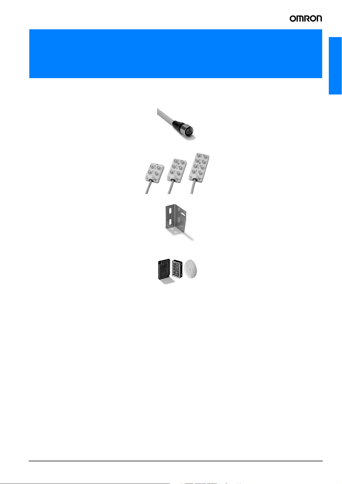
Accessories for Standard Sensors (photoelectric, inductive, capacitive)
Sensor Accessories
Cable connectors . . . . . . . . . . . . . . A-2
Extended wiring accessories . . . . . . A-19
Mounting brackets . . . . . . . . . . . . A-28
Reflectors . . . . . . . . . . . . . . . . . A-34
A-1
Page 2
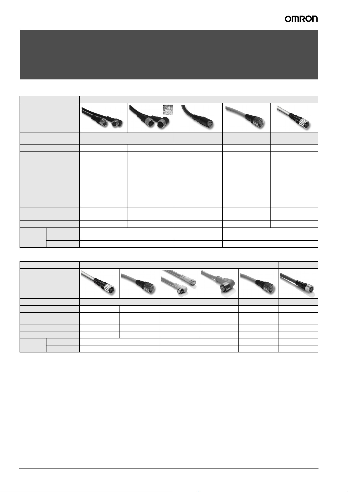
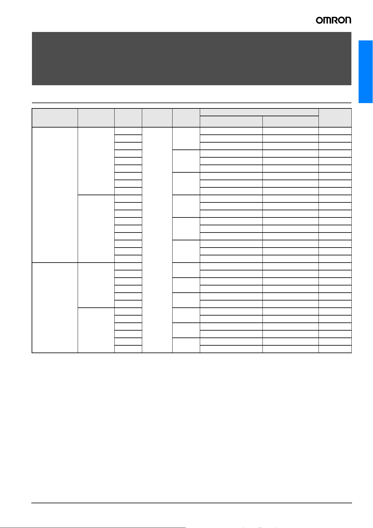
Cable Connectors
Product group Cable Connectors
Typ e General purpose (screw)
Order reference Y92E-M08 Y92E-M12 Y92E-MS08 XS2F-@-A XS3F-@-A
Recommended Sensors
Material
Recommended Sensors
Material
Applicable/
Features
Size M8 M12 M8 M12 M8
Nut
Cable PVC or PUR PVC or PUR PVC
Product group Cable Connectors
Typ e Robot cable (vibration resistant) Detergent resistant Fire retardant Spatter proof
Order reference XS3F-@-R XS2F-@-R Y92E-S08 Y92E-S12 XS2F-@-F XS2F-@-AS
Applicable/
Features 4 pin 3, 4 or 5 wire 3 or 4 pin 4 wire 3, 4 or 5 wire 4 wire
Size M8 M12 M8 M12 M12 M12
Nut brass stainless steel brass brass
Cable PVC PVC PVC Polyethylene
General purpose
(snap)
Inductive:
E2A-@-M5,
E2A-@-M3,
E2E small diameter,
E2EL, E2C-EDA
photoelectric: E3Z,
E3G-L1/L3, E3C,
E3X
All sensors with
M8-junction connectors -M3J, -M5J
- 3 or 4 pin
- LED optionally
Brass (CuZn) or
zinc diecast (ZnAl Cu)
See Y92E-M08 See Y92E-M12 E3ZM E2FM See Y92E-M12 E2FM
Photoelectric:
E3F2, E3G-(M)R,
E3G-(M)L7, E3S-C,
E3MV, E3NT
Inductive:
E2@-@-M1, E2E,
E2E@, E2F
All sensors with
M12 junction connector -M1J
- 3, 4 or 5 wire
- LED optionally
Inductive:
E2A-@-M5,
E2A-@-M3,
E2E small diameter,
E2EL, E2C-EDA
Photoelectric: E3Z,
E3G-L1/L3, E3C,
E3X
3 or 4 pin 2, 3, 4 or 5 wire 4 pin
PUR brass
General purpose -
extended wiring
See Y92E-M12 plus
AC 2-wire types:
E2E-@Y, E2F-@Y,
E3F2-@Z
small size
(screw or snap)
Inductive:
E2A-@-M3,
E2E small diameter,
E2EL, E2C-EDA
Photoelectric:
E3Z, E3G-L1/L3,
E3C, E3X
All sensors with
M8-junction connectors -M3J
A-2 Standard Photoelectric Sensors
Page 3
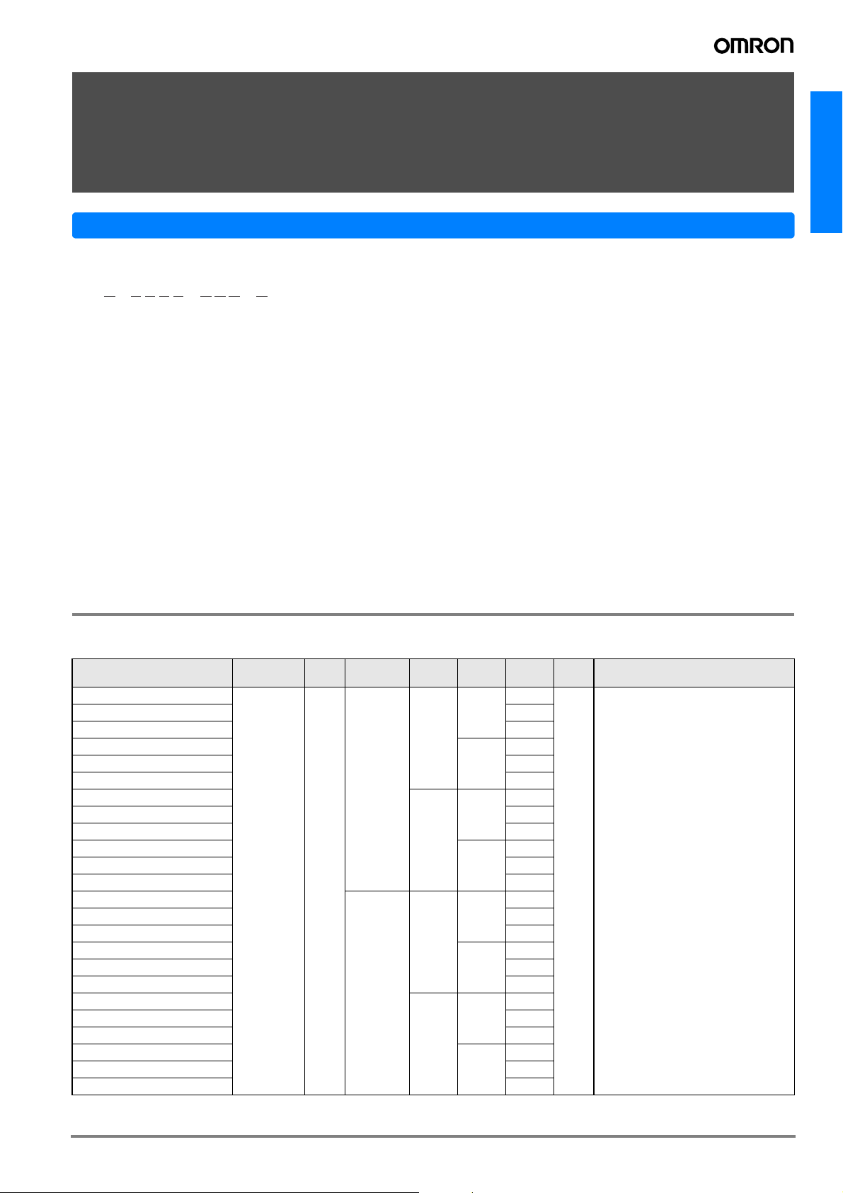
General Purpose Cable Connectors (M8 / M12)
Y92E
Y92E - @@@@ - @@@ - @
1234
1. Connector type
M: standard female screw on connector
S: stainless steel female screw on connector
MM: male metric screw plug
MS: female snap connector
2. Size
08: M8 size
12: M12 size
3. Material
PVC: PVC cable
PUR: PUR cable
5 678 9
Model Number Legend
4. Nr of poles
3: 3 poles
4: 4 poles
5: 5 poles
5. Shape
A: angled
S: straight
6. Length
2M: standard 2 m length
5M: standard 5 m length
10M: standard 10 m length
7. LED
LED: with LED
[blank]: no LED
8. Specials
9. Supply code
-L designed and manufactured by Lumberg
-H designed and manufactured by Hirschmann
Ordering information
General purpose models
Product description
Y92E-M08PUR3A2M-x
Y92E-M08PUR3A5M-x 5
Y92E-M08PUR3A10M-x 10
Y92E-M08PUR3S2M-x
Y92E-M08PUR3S5M-x 5
Y92E-M08PUR3S10M-x 10
Y92E-M08PUR4A2M-x
Y92E-M08PUR4A5M-x 5
Y92E-M08PUR4A10M-x 10
Y92E-M08PUR4S2M-x
Y92E-M08PUR4S5M-x 5
Y92E-M08PUR4S10M-x 10
Y92E-M08PVC3A2M-x
Y92E-M08PVC3A5M-x 5
Y92E-M08PVC3A10M-x 10
Y92E-M08PVC3S2M-x
Y92E-M08PVC3S5M-x 5
Y92E-M08PVC3S10M-x 10
Y92E-M08PVC4A2M-x
Y92E-M08PVC4A5M-x 5
Y92E-M08PVC4A10M-x 10
Y92E-M08PVC4S2M-x
Y92E-M08PVC4S5M-x 5
Y92E-M08PVC4S10M-x 10
1
Connector Size
female M8
Cable
material
PUR
PVC
Poles Type
Angled
3
Straight
Angled
4
Straight
Angled
3
Straight
Angled
4
Straight
Length
(m)
2
2
2
2
2
2
2
2
LED Nut
-H: Zinc diecast (ZnAl Cu)
no
-L: brass (CuZn)
A-3
Page 4
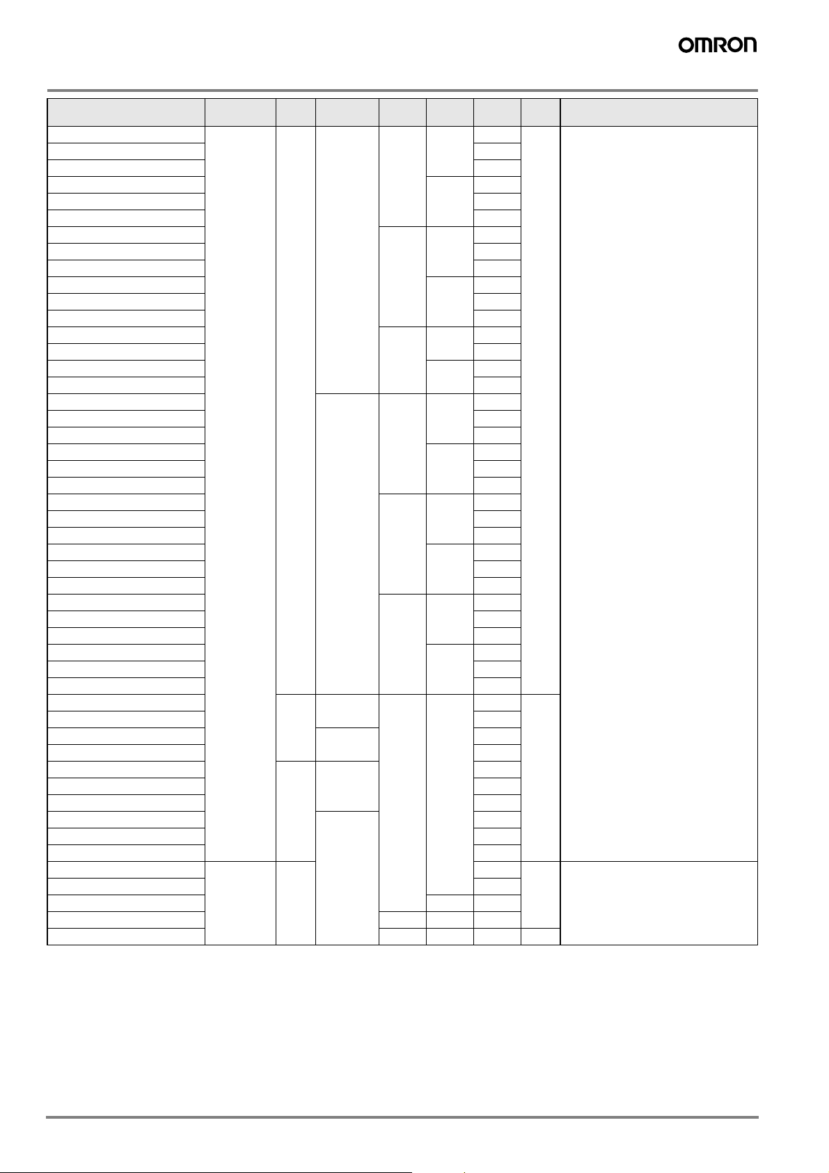
Product description
1
Connector Size
Cable
material
Poles Type
Y92E-M12PUR3A2M-x
Y92E-M12PUR3A5M-x 5
Y92E-M12PUR3A10M-x 10
Y92E-M12PUR3S2M-x
3
Y92E-M12PUR3S5M-x 5
Angled
Straight
Length
(m)
2
2
Y92E-M12PUR3S10M-x 10
Y92E-M12PUR4A2M-x
Y92E-M12PUR4A5M-x 5
Y92E-M12PUR4A10M-x 10
Y92E-M12PUR4S2M-x
PUR
4
Y92E-M12PUR4S5M-x 5
Angled
Straight
2
2
Y92E-M12PUR4S10M-x 10
Y92E-M12PUR5A2M-x
Y92E-M12PUR5A5M-x 5
Y92E-M12PUR5S2M-x
5
Y92E-M12PUR5S5M-x 5
Y92E-M12PVC3A2M-x
Y92E-M12PVC3A5M-x 5
Y92E-M12PVC3A10M-x 10
Y92E-M12PVC3S2M-x
M12
3
Y92E-M12PVC3S5M-x 5
Y92E-M12PVC3S10M-x 10
Y92E-M12PVC4A2M-x
female
Y92E-M12PVC4A5M-x 5
Y92E-M12PVC4A10M-x 10
Y92E-M12PVC4S2M-x
PVC
4
Y92E-M12PVC4S5M-x 5
Angled
Straight
Angled
Straight
Angled
Straight
2
2
2
2
2
2
Y92E-M12PVC4S10M-x 10
Y92E-M12PVC5A2M-x
Y92E-M12PVC5A5M-x 5
Y92E-M12PVC5A10M-x 10
Y92E-M12PVC5S2M-x
5
Y92E-M12PVC5S5M-x 5
Angled
Straight
2
2
Y92E-M12PVC5S10M-x 10
Y92E-M08PUR3A2MLED-x
Y92E-M08PUR3A5MLED-x 5
Y92E-M08PVC3A2MLED-x
Y92E-M08PVC3A5MLED-x 5
PUR
M8
PVC
Y92E-M12PUR3A2MLED-x
M12
PUR
3
Angled
Y92E-M12PUR3A5MLED-x 5
Y92E-M12PUR3A10MLED-x 10
Y92E-M12PVC3A2MLED-x
2
2
2
2
Y92E-M12PVC3A5MLED-x 5
Y92E-M12PVC3A10MLED-x 10
Y92E-MS08PVC3A2M-x
Y92E-MS08PVC3A5M-x 5
Y92E-MS08PVC3S5M-x Straight 5
Y92E-MS08PVC4S5M-x 4 Straight 5
female
(snap)
PVC
M8
2
Y92E-MS08PVC3A5MLED-x 3 Angled 5 yes
1
‘-L‘ or ‘-H‘ are added to the product description
LED Nut
no
-H: Zinc diecast (ZnAl Cu)
-L: brass (CuZn)
yes
no
Snap (PUR)
A-4 Standard Photoelectric Sensors
Page 5
Detergent resistant models
M8
M12
Cable
material
PVC 4
Poles Type
Angled
Straight
Angled
Straight
Product description Connector Size
Y92E-S08PVC4A2M-L
Y92E-S08PVC4A5M-L 5
Y92E-S08PVC4S2M-L
Y92E-S08PVC4S5M-L 5
Y92E-S12PVC4A2M-L
female
Y92E-S12PVC4A5M-L 5
Y92E-S12PVC4C2M-L
Y92E-S12PVC4S5M-L 5
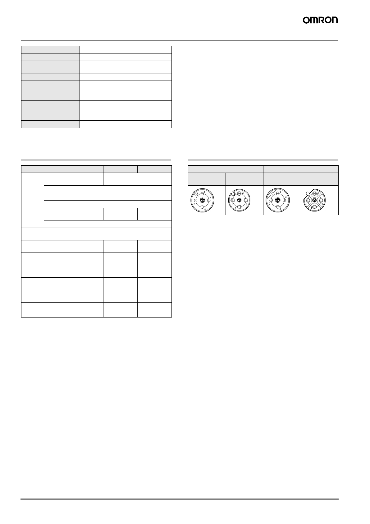
Specifications
Rated current 4A
M8 3 pin: 60 V
M8 4 pin: 60 V (-H), 30 V (-L)
Rated voltage
Degree of protection IP67
Ambient temperature
Specials
M12 3- or 4-wire: 240 V
M12 5-wire: 60 V
with LED: 10-30 V
-25 to +70 °C M8 and M12 (PVC cable)
-25 to +80 °C M8 and M12 (PUR cable)
-H: Silicone-free
PUR cable: Halogene-free
Length
(m)
2
2
2
2
LED Nut
no SUS
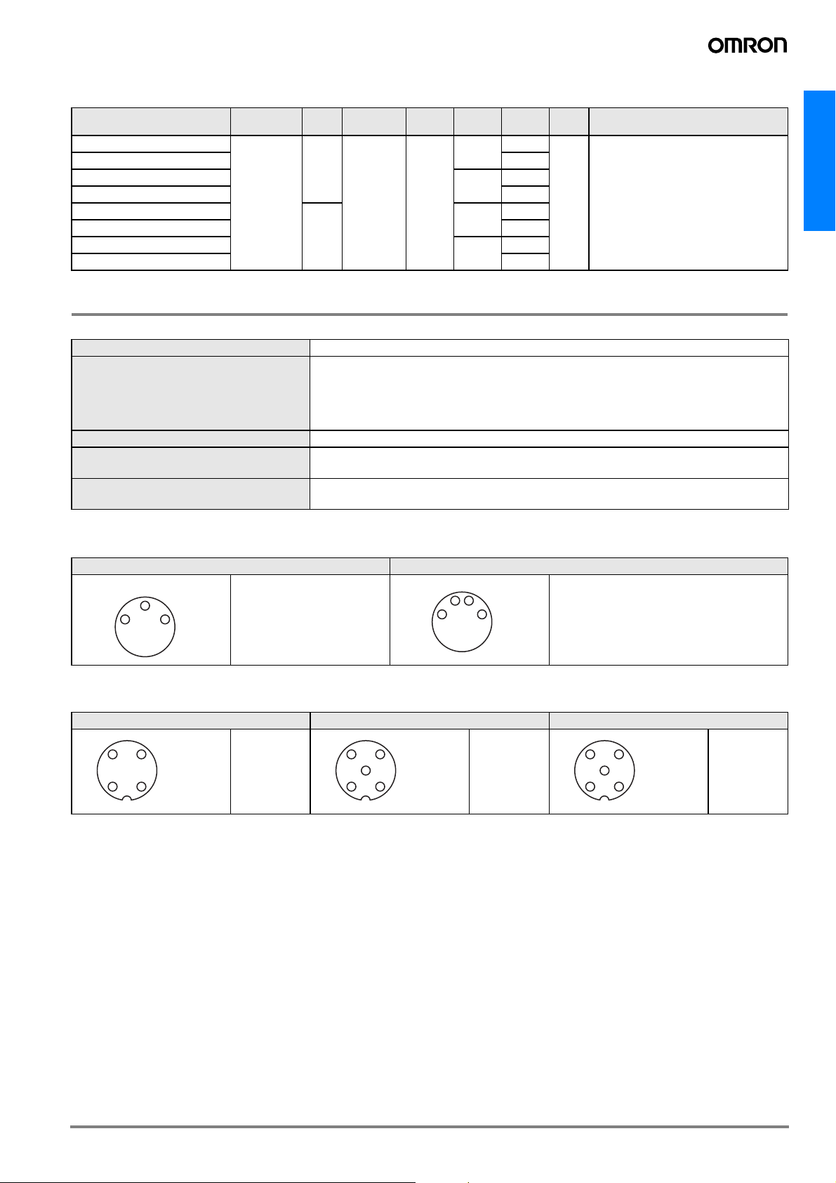
M8 pin assignment
3 poles 4 poles
4
31
1 = brown
3 = blue
4 = black
42
31
1 = brown
2 = white
3 = blue
4 = black
M12 pin assignment
3 poles 4 poles 5 poles
34
21
1 = brown
2 = n.c.
3 = blue
4 = black
34
5
21
1 = brown
2 = white
3 = blue
4 = black
5 = n.c.
34
5
21
1 = brown
2 = white
3 = blue
4 = black
5 = green /
yellow
A-5
Page 6
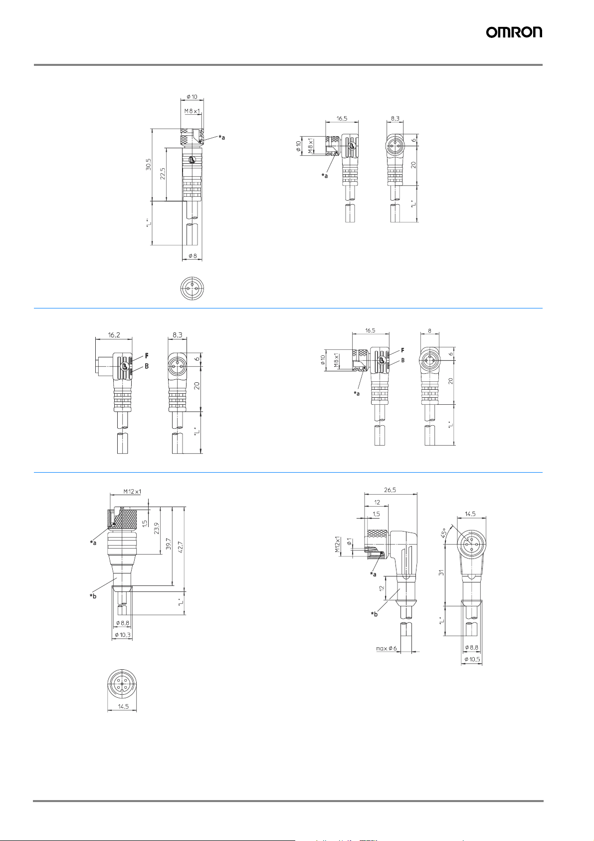
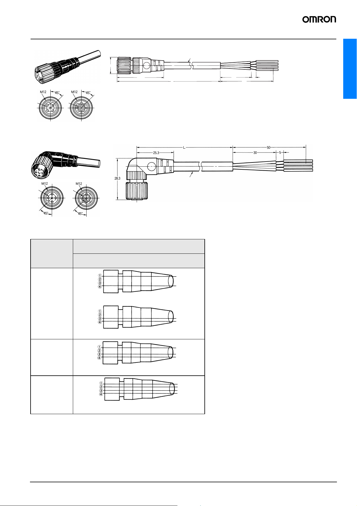
Dimensions
General purpose
Y92E-M08@-L
Y92E-M08@-LED-L
*a O-Ring
O-ring
Y92E-M12@-L
B Betriebsanzeige grün
operation indicator green
F Funktionsanzeige gelb
function indicator yellow
*a O-Ring
O-ring
*b Schutzschlauchmontage
hose mounting
*a O-Ring
O-ring
A-6 Standard Photoelectric Sensors
Page 7
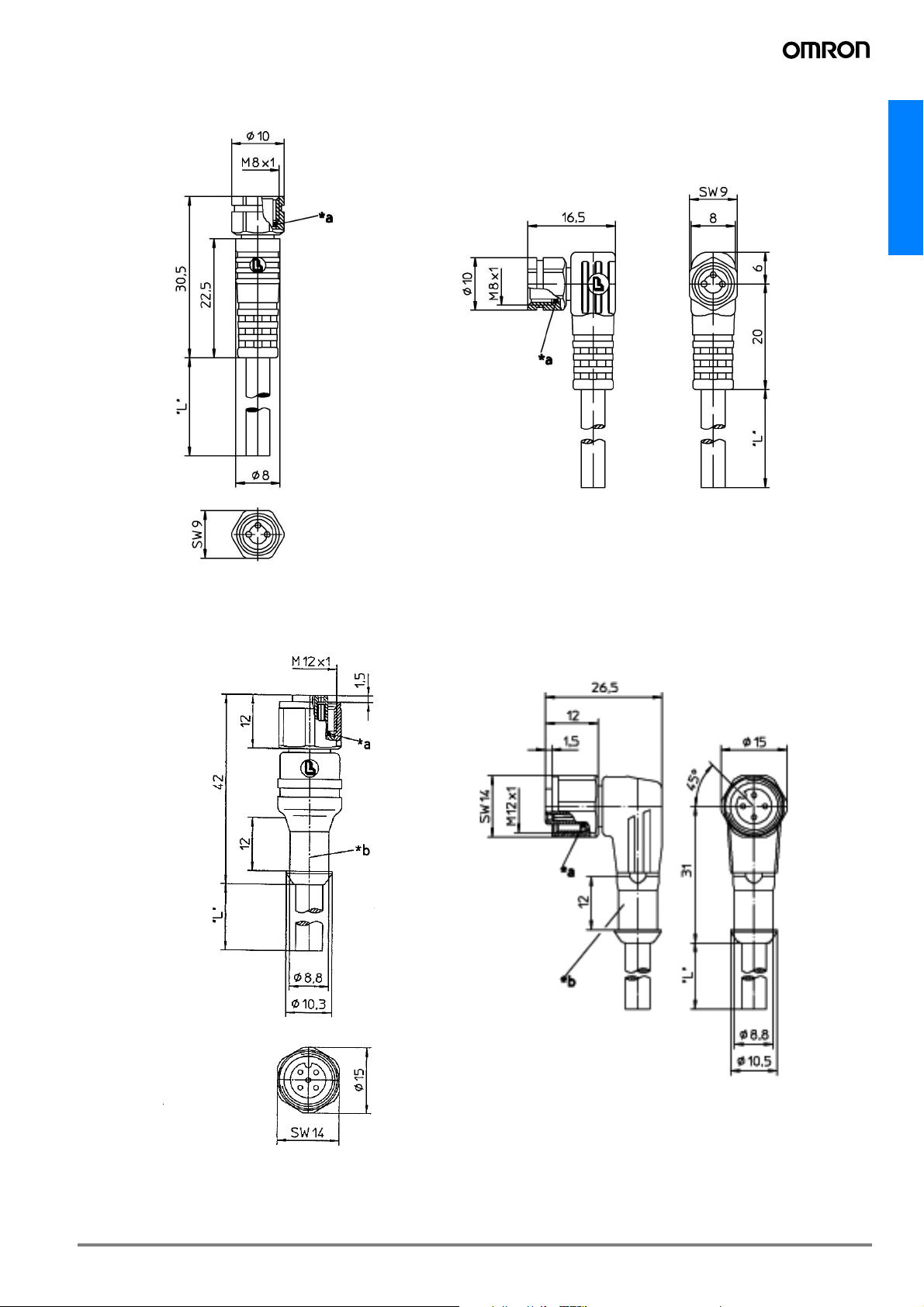
Detergent resistant
Y92E-S08
Y92E-S12
A-7
Page 8
M12 Extended Wiring and Robot Cable Connectors
XS2F
Model Number Legend
Use this model number legend to identify products from their model number. When ordering, use a model number from the table in
Ordering Information.
XS2F - @@2@ - @@0 - @
1234
5 678 9
1. Type
F: Connector connected to cable, socket on one cable end
2. AC/DC (Mating Section Form)
A: For AC
D: For DC
3. Connector Poles
4: 4 poles
5: 5 poles
4. Contact Plating
2: 0.4-μm gold plating
5. Cable Connection Direction
1: Straight
2: L-shaped (angled)
6. Cable Length
A: 0.3 m
B: 0.5 m
C: 1 m
D: 2 m
E: 3 m
F: 4 m
G: 5 m
H: 7 m
J: 10 m
K: 15 m
L: 20 m
Only the 2 m (D) and 5 m (G) cables are available for cables with
5 poles.
7. Connections
Pin No.
1234
A: Brown --- --- Blue (for DC)
B: --- --- Brown Blue (for AC)
C: Brown --- Blue Black
8: Brown White Blue Black (for DC)
9: Brown White Blue Black (for AC)
Pin No.
12345
G: Brown White Blue Black Gray
8. Connectors on One End/Both Ends
0: One end
9. Cable Specifications
A: Standard cable
R: Vibration-proof robot cable (straight/straight only)
F: Fire-
AS: Spatter proof
retardant, vibration-proof cable
A-8 Standard Photoelectric Sensors
Page 9
XS2F-@42@-@@0-A Connectors with Standard Cable (2, 3 or 4 wires)
XS2F-@42@-@@0-R Connectors with Vibration-proof Robot Cable
Ordering Information
XS2F
Cable type Cable
Standard cable Straight 2
Vibration-proof
robot cable
connection
direction
L-shaped
(angled)
Straight 2 2 XS2F-D421-DA0-R XS2F-A421-DB0-R ---
L-shaped
(angled)
No. of
cable
cores
3 XS2F-D421-DC0-A --- --4 XS2F-D421-D80-A XS2F-A421-D90-A Yes
2 5 XS2F-D421-GA0-A XS2F-A421-GB0-A --3 XS2F-D421-GC0-A --- --4 XS2F-D421-G80-A XS2F-A421-G90-A Yes
2 10 XS2F-D421-JA0-A XS2F-A421-JB0-A --3 XS2F-D421-JC0-A --- --4 XS2F-D421-J80-A XS2F-A421-J90-A Yes
2 2 XS2F-D422-DA0-A XS2F-A422-DB0-A --3 XS2F-D422-DC0-A --- --4 XS2F-D422-D80-A --- Yes
2 5 XS2F-D422-GA0-A XS2F-A422-GB0-A --3 XS2F-D422-GC0-A --- --4 XS2F-D422-G80-A --- Yes
2 10 XS2F-D422-JA0-A XS2F-A422-JB0-A --3 XS2F-D422-JC0-A --- --4 XS2F-D422-J80-A --- Yes
4 XS2F-D421-D80-R XS2F-A421-D90-R --2 5 XS2F-D421-GA0-R XS2F-A421-GB0-R --4 XS2F-D421-G80-R XS2F-A421-G90-R --2 10 XS2F-D421-JA0-R XS2F-A421-JB0-R --4 XS2F-D421-J80-R XS2F-A421-J90-R --2 2 XS2F-D422-DA0-R XS2F-A422-DB0-R --4 XS2F-D422-D80-R --- --2 5 XS2F-D422-GA0-R XS2F-A422-GB0-R --4 XS2F-D422-G80-R --- --2 10 XS2F-D422-JA0-R XS2F-A422-JB0-R --4 XS2F-D422-J80-R --- ---
Core
diameter
0.5 mm
Cable
length
(m)
2
2 XS2F-D421-DA0-A XS2F-A421-DB0-A ---
DC AC
Model UL-listed
A-9XS2F
Page 10
Specifications
Rated current 3 A
Rated voltage 125 VDC, 250 VAC
Contact resistance
Insulation resistance 1,000 MΩ min. (at 500 VDC)
Dielectric strength
Degree of protection IP67 (IEC529)
Insertion tolerance 200 times min.
Assembled fixture
strength
Ambient temperature Operating: -25°C to 70°C
Note: 1 .The contact resistance of the connector.
2 .The dielectric strength of the connector.
40 mΩ max. (20 mV max., 100 mA max.)
(See note 1).
1,500 VAC for 1 min (leakage current:
1 mA max.) (See note 2).
Tensile: 98 N/15 s
Torsion: 0.98 N·m/15 s
Materials and Finish
Item XS2F XS2R XS2C/XS2G
Contacts
Fixtures
Pin
Block
O-ring/rubber bushing
Cover
Cap --- ---
Cable clamp --- ---
Pin clamp --- ---
Lock spring --- ---
Watertight bushing --- --- Rubber
Ring --- --- Steel
Note: The T-joint of the XS2R is aluminum/white.
Materials
Finish Nickel base, 0.4-μm gold plating
Materials Brass (See note 1.)
Finish Nickel plated (See note 1.)
Materials
Finish For DC: light gray; for AC: dark gray
Phosphor
bronze
PBT resin
(UL94V-0)
Rubber
Polyester
elastomer
Brass
PA resin
(UL94V-0)
---
PBT resin
(UL94V-0)
PBT resin
(UL94V-0)
PBT resin
(UL94V-0)
PA resin
(UL94V-0)
PBT resin
(UL94V-0)
LCP resin
(UL94V-0)
Socket Appearance
DC type AC type
Male contacts
Note: The AC and DC connectors are different as shown here and therefore
cannot be connected together.
Female
contacts
Male contacts
Female
contacts
A-10 Standard Photoelectric Sensors
Page 11
Dimensions
Straight Connectors
5 dia. 5 dia.
DC AC
L-shaped Connectors
5 dia.
5 dia.
14.9 dia.
6 dia.
40.7 30
L50
6 dia.
5
XS2
DC AC
Wiring Diagram
Item
Two-core model
Three-core model
Four-core model
Standard cable
Vibration-proof robot cable
XS2F-@42@-@@0-A
XS2F-@42@-@@0-R
Contact
No.
Contact
No.
Contact
No.
Contact
No.
Brown
Blue
(DC)
Cable lead colors
Brown
Blue
(AC)
Cable lead colors
Brown
Blue
Black
(DC)
Cable lead colors
Brown
White
Blue
Black
(DC/AC)
Cable lead colors
A-11XS2
Page 12

5-wire Connectors for DC
XS2F-D521-@G0-A
Ordering Information
Cable connection
direction
Straight 5
No. of cable cores
Cable core crosssectional area
2
0.3 mm
Cable length (m)
2 XS2F-D521-DG0-A
5 XS2F-D521-GG0-A
Dimensions
Straight Connectors
Note: Use the XS2F-D521-@G0-A in combination
with the XS2H-D521-@G0-A.
M12
45°
5 dia.
14.9 dia.
Wiring Diagram Pin Arrangements (Engagement Side)
Contact No.
18
34
48
L
6 dia.
DC
Model
30
5
50
Brown
White
Blue
Black
Gray
Cable lead colors
A-12 Standard Photoelectric Sensors
Page 13

XS2 Connector Covers
Water-resistive Covers
XS2Z-11
M12 male screwXS2Z-11
M12
XS2Z-12
M12 x 1.0 female screw
M12XS2Z-12
The Water-resistive Cover ensures IP67. When mounting the Water-resistive Cover to a Connector, be sure to apply a torque range between 0.39
and 0.49 N·m to tighten the Water-resistive Cover.
(thread bracket)
Ordering Information
XS2
Model Minimum order Material
XS2Z-11
XS2Z-12 XS2R/XS2F/XW3B M12 female screw (thread bracket)
Note: Orders are accepted in multiples of the minimum order.
50 Brass/nickel plated
Suitable connector
Model Mounting portion
XS2R M12 male screw
Dust Covers
XS2Z-13
XS2Z-13
The Dust Cover is for dust prevention and does not ensure IP67 degree of protection. When mounting the Dust Cover to a connector, be sure to
press the Dust Cover onto the Connector until the Connector is fully inserted into the Dust Cover.
XS2Z-15/XS1Z-14
XS2Z-15
M12 male screw
XS2Z-14
Pin block (female pins)
M12 female screw
(thread bracket)
Ordering Information
Model
XS2Z-13
XS2Z-14
XS2Z-15 M12 female screw (thread bracket)
Note: Orders are accepted in multiples of the minimum order.
Minimum
order
50
Material
Transparent polyvinyl chloride XS2R M12 male screw
Red polyvinyl chloride XS2R/XS2F/XW3B
Suitable connector
Model Mounting portion
Pin block (female pins)
A-13XS2
Page 14

M8 Small Size and Robot Cable Connectors
XS3F
Model Number Legend
Use this model number legend to identify products from their model number. When ordering, use a model number from the table in
Ordering Information.
XS3F - @42@ - 4@@ - @
1234
5 678 9
1. Fastening Method
M: M8
S: S8
2. Connector Poles
4: 4 poles
3. Cable Connection Direction
1: Straight
2: L-shaped
Ordering Information
M8 Model
Item
Standard cable
Vibration-proof robot
cable
Cable connection
direction
Straight
L-shaped
Straight
L-shaped
No. of cable
cores
4
4
4. Connections
1234
4: Brown White Blue Black
5. Cable Length
01: 1 m
02: 2 m
05: 5 m
6. Cable Specifications
A: Standard cable
R: Vibration-proof robot cable
Cable core
crosssectional area
2
0.2 mm
Cable length (m) Model
2 XS3F-M421-402-A
5 XS3F-M421-405-A
2 XS3F-M422-402-A
5 XS3F-M422-405-A
1 XS3F-M421-401-R
2 XS3F-M421-402-R
5 XS3F-M421-405-R
1 XS3F-M422-401-R
2 XS3F-M422-402-R
5 XS3F-M422-405-R
Pin No.
S8 Model
Cable connection
direction
Straight
L-shaped
No. of cable
cores
4
Cable core cross-sectional area Cable length (m) Model
1 XS3F-S421-401-R
2 XS3F-S421-402-R
0.2 mm
2
5 XS3F-S421-405-R
1 XS3F-S422-401-R
2 XS3F-S422-402-R
5 XS3F-S422-405-R
A-14 Standard Photoelectric Sensors
Page 15

Specifications
Rated current 1 A
Rated voltage 125 VDC
Contact resistance
Insulation resistance 1,000 MΩ min. (at 500 VDC)
Dielectric strength
Degree of protection IP67 (IEC529)
Insertion tolerance 200 times
Cable tensile strength 50 N/15 s)
Ambient temperature Operating: -25°C to 70°C
Note: 1 .The contact resistance of the connector.
2 .The dielectric strength of the connector.
40 MΩ max. (20 mV max., 10 mA max.)
(See note 1.)
1,000 VAC for 1 min (leakage current:
1 mA max.) (See note 2.)
Materials and Finish Pin Arrangement (Engaged Side)
XS3
Pin Block PBT resin/light gray or black
Contacts Brass/nickel base, 0.4-μm gold plating
Thread bracket (M8)
Shell (S8)
Cover Thermoplastic elastomer/black
O-ring Rubber
Brass/nickel plated
Plug
DC
Socket
A-15XS3
Page 16

Dimensions
M8 Screw-on cable connectors
Straight Connectors
2.15
4
1.95 0.5
L-shaped Connectors
3
3.4
M8
1
L
4 dia.
4 dia.
30
5
50
12.9
2
9 dia.
21.5
31.4
9 dia.
12
34
Wiring Diagram
Contact No.
Brown
White
Blue
Black
Cable lead colors
A-16 Standard Photoelectric Sensors
Page 17

Dimensions
M8 Snap-in cable connectors
Straight Connectors
3
0. 5
1.95
2.15
2
4
1
3.4
13.9
21.1
30.7
4 dia.
XS3
30
L
5
50
L-shaped Connectors
Wiring Diagram
Contact No.
19.8
8.2 dia.
2
4
2.15
Brown
White
Blue
Black
Cable lead colors
1
3
0.5
1.95
23.1
3.4
L5 0
4 dia.
30
5
A-17XS3
Page 18

Precautions
Refer to Correct Use for precautions for individual products.
Correct Use
Connections
• The XS3 and XS2 Sensor I/O Connectors cannot be connected to
each other.
• When using Sensors with Connectors or Limit Switches, use the
Sensor I/O Connectors specified in the catalog.
• Do not connect M8 screw models and S8 snap-in models together,
otherwise the proper degree of protection of the Connectors will not
be maintained.
Connector Connection and Disconnection
• Before connecting or disconnecting Connectors, make sure that no
power is being supplied to the Connectors.
• When connecting or disconnecting Connectors, be sure to hold the
Connectors by hand.
• Do not touch the engagement side of any Connector with wet
hands. If there is any water on the Connector or near the Connector, be sure to wipe off the water before connecting or disconnecting the Connector, otherwise the Connector may short-circuit
internally or not ensure good insulation.
• Make sure that engagement side of any Connector is free of metal
dust or power.
• Do not use pliers to tighten mounting the thread bracket, otherwise
the thread bracket may be damaged. Be sure to tighten each
thread bracket by hand within a torque of 0.3 and 0.4 N·m. If the
thread bracket is not tightened securely, the Connector may not
maintain its proper degree of protection or the thread bracket may
fall off due to vibration.
• Fully insert S8 snap-in models until the Connectors are hidden by
the metal casing of the opposite parts, otherwise the Connectors
will not maintain their proper degree of protection or the thread
brackets may drop off due to vibration.
Cable Wire Color
• The M8/S8 Sensor I/O Connectors use the following lead wire colors.
Model Pin No.
1 2 3 4
DC 8-mm-dia.
DC4
Brown White Blue Black
Degree of Protection
• Do not impose external force continuously on the joints of pin
blocks and covers, otherwise the Connectors may not keep its
proper degree of protection (i.e., IP67).
• Connectors are not fully watertight. Do not use them underwater.
• The Connectors are not oil-resistant. Do not use them where they
would be subject to oil.
• If Connectors are used in places with vibration or shock, secure the
engaged side of each Connector, otherwise the Connectors may
be disconnected or fail to maintain their proper degree of protection.
• Connectors are of resin mold construction. Do not impose excessive force on them.
Storage
Do not store Connectors for long periods of time in the following
locations
• Locations subject to dust or high humidity
• Locations subject to ammonia gas or sulfide gas
A-18 Standard Photoelectric Sensors
Page 19

Connector terminal boxes and extended wiring accessories
Overview
Accessories
Shape
Product
group
Extended wiring accessories
Type
M12 I/O connector terminal
boxes
I/O connector
terminal boxes
for bus
connection
Waterproof
cover for M12
I/O connector
M12 T-joint and
Y-joint plugs
Housing
material
- PBT case
- brass
connectors
Please contact your OMRON representative for our large portfolio of remote I/O
brass
- PVC cable
- brass nut
Features
-flat size
-for M12
connectors
- 4, 6 or 8 contacts
per box
water proof cover
for IP67 rating of
X3WB
- daisy chain
model for ’AND’
configurations
(T-joint)
- direct wiring
models for ’OR’
configurations
(Y-joint)
- bifurcate models for signal
splitting
- aggregate models for reduced
wiring
Key
specifications
-4A / port
- 10 or
30 V DC
- 4 or 5-pin
-IP67
- 3 A rated
current
-DC
-4-pin
-IP67
Order
reference
XW3B
XS2Z-12
XS2R
for all sensors
connected via M12
4-pin connections &
cables
- sensors with
built-in M12 4-pin
connector (-M1)
- sensors with M12
4-pin cable end
connector (-M1J)
Applicable
Sensors
- PBT case
M8 Y-joint plugs
12
Note: 1 .Please contact your OMRON representative for these models
- brass
connectors
- direct wiring
models for ’OR’
configurations
- aggregate models for reduced
wiring
- 1 A rated
current
-125VDC
-4-pin
-IP67
XS3R
- sensors with built
in M8 4-pin
connector (-M3)
- sensors with M8
4-pin cable end
connector
A-19Accessories
Page 20

M12 Connector Terminal Boxes
XW3B
Materials and Finish
Item Part name Materials and finish
Anchor Brass/nickel plated
Connectors
Cable Cable
Case
Note: The positive power supply, negative power supply, and ground lines are
AWG18. Signal lines are AWG22.
Contacts
Case PBT resin (UL94V-0)/light gray
Bushing Rubber
PCB Glass-epoxy board
Seal resin Urethane resin
Brass/nickel base, 0.4-μm gold plating
Sheath color: gray
Core size: AWG18/AWG22
(See note.)
Ratings and Characteristics
Rated current
Rated voltage 10 to 30 VDC
Contact resistance
Insulation resistance 100 MΩ min. (at 500 VDC)
Dielectric strength
Degree of protection IP67 (IEC529)
Cable retention force 98 N/15 s
Insertion tolerance 200 times
Operating
temperature
Note: 1 .The contact resistance of the Connector.
2 .The dielectric strength of the Connector.
4 A/port (signal lines)
12 A/box (power lines)
40 MΩ max. (with 100 mA max.,
20 mV max.) (See note 1.)
500 VAC for 1 min (leakage current:
1 mA max.) (See note 2.)
-25 to 70°C
Compatible Connectors *1
Connector Plug Assemblies
XS2G
(crimping, soldering, or screw-on)
XS2W Connectors on cable ends (Sockets or Plugs)
XS2H Connectors on one cable end (Plugs)
Note: 1 .Please refer to seperate datasheet X073-E1-01 for these models.
A-20 Standard Photoelectric Sensors
Page 21

Ordering Information
Sensor type and connections 3-wire DC NPN/2-wire 3-4
2-wire DC1-4/without polarity
3-4
3-wire DC PNP/2-wire DC 1-4
Actuator connections Actuator connections 1-4 --- Actuator connections 3-4
No. of ports Cable length (m) Model Model Model
4 5 XW3B-P455-G11 XW3B-P452-G11 XW3B-P453-G11
6 5 XW3B-P655-G11 XW3B-P652-G11 XW3B-P653-G11
8 5 XW3B-P855-G11 XW3B-P852-G11 XW3B-P853-G11
Note: Here 1-4 and 3-4 are connector pin numbers.
Waterproof Cover (Sold Separately)
XW2Z-12
Model Materials
XW2Z-12 Brass/nickel plated
Note:The XW3B/XW3A comes with a dust cover. Use the optional XW2Z-12
Waterproof Cover when an IP67 degree of protection is required.
Connection Diagram
Standard Japanese Specification
XW3B-P@55-G11 for 3-wire DC NPN,
2-wire DC (without polarity 3-4), and
Actuator (1-4)
3-Wire
NPN
Positive power
supply (Brown)
+ −
Signal 1
1
(White)
Lead
color
Signal 2
2
(Green)
Signal 3
3
(Yellow)
4
Signal 4
(Gray)
Signal 5
5
(Pink)
Signal 6
6
(Red)
Signal 7
7
(Black)
Signal 8
8
(Purple)
Note: 1 .The above wiring diagrams are for eight-port use.
2 .Figures in parentheses indicate lead colors.
3 .The expression “white/red” means white and red stripes.
4 .Here 1-4 and 3-4 are pin numbers.
5 .Contact numbers 5 through 8 in the above diagrams do not exist on Terminal Boxes with four inputs. The
lead colors for signals 1 through 4, power supply, and ground are the same.
6 .Contact numbers 7 and 8 in the above diagrams do not exist on Terminal Boxes with six inputs. The lead
colors for signals 1 through 6, power supply, and ground are the same.
Negative power
supply (Blue)
Power indicator
(Green LED)
Operation indicator
(Red LED)
Connector
pin number
Connector
1
42
5
3
1
42
5
3
1
42
5
3
1
42
5
3
1
42
5
3
1
42
5
3
1
42
5
3
1
42
5
3
(Green/Yellow)
number
No. 1
No. 2
No. 3
No. 4
No. 5
No. 6
No. 7
No. 8
Japanese Specification
XW3B-P@52-G11 for 2-wire DC (with polarity 1-4,
without polarity 3-4)
Note: Cannot be used with NPN-type Photoelectric and Prox-
imity Sensors.
Cannot be used with Proximity Sensors with polarity 3-4.
2-Wire
Ground
Positive power
supply (Brown)
Signal 1
(White)
Lead
color
Signal 2
(Green)
Signal 3
(Yellow)
Signal 4
(Gray)
Signal 5
(Pink)
Signal 6
(Red)
Signal 7
(Black)
Signal 8
(Purple)
1
2
3
4
5
6
7
8
+ −
Negative power
supply (Blue)
Power indicator
(Green LED)
Operation indicator
(Red LED)
Connector
pin number
Connector
1
42
5
3
1
42
5
3
1
42
5
3
1
42
5
3
1
42
5
3
1
42
5
3
1
42
5
3
1
42
5
3
number
No. 1
No. 2
No. 3
No. 4
No. 5
No. 6
No. 7
No. 8
Ground
(Green/Yellow)
European Specification
XW3B-P@53-G11 for 3-wire DC PNP,
2-wire DC (with polarity 1-4), and
Actuator (3-4)
3-Wire
PNP
Positive power
supply (Brown)
Signal 1
(White)
Lead
color
Signal 2
(Green)
Signal 3
(Yellow)
Signal 4
(Gray)
Signal 5
(Pink)
Signal 6
(Red)
Signal 7
(Black)
Signal 8
(Purple)
1
2
3
4
5
6
7
8
+ −
Negative power
supply (Blue)
Power indicator
(Green LED)
Operation indicator
(Red LED)
Connector
pin number
Connector
1
42
5
3
1
42
5
3
1
42
5
3
1
42
5
3
1
42
5
3
1
42
5
3
1
42
5
3
1
42
5
3
number
Ground
(Green/Yellow)
No. 1
No. 2
No. 3
No. 4
No. 5
No. 6
No. 7
No. 8
XW3B
A-21XW3B
Page 22

Dimensions
4
2
3
1
4
2
3
1
65
4
2
3
1
65
8
7
XW3B-P45@-G11 (Four Input Ports)
Power indicator (green LED)
Operation indicator (red LED)
73
4.5
Three, 4.5 dia.
6.9 dia.
100
120
33 5427
10
L
XW3B-P65@-G11 (Six Input Ports)
XW3B-P85@-G11 (Eight Input Ports)
9 27 30.5
6.5
13.5
9
6.5
13.5
4.5 dia.
14 dia.
82
14 dia.9 dia.
9
Internal connection indication
Power indicator (green LED)
Operation indicator (red LED)
73
2727 30.5
100
73
4.5
Three, 4.5 dia.
7.7 dia.
L
9
Internal connection indication
Power indicator (green LED)
Operation indicator (red LED)
4.5
Three, 4.5 dia.
L
100
9
120
20
8.2 dia.
100
10
9
120
33 5427
20
33 5427
10
9
Internal connection indication
Three, M4 or 4.5 dia.
33±0.1
20
9
6.5
13.5
14 dia. 9 dia.
4.5 dia.
Mounting holes
73±
127
0.1
272727 30.5
Note: Mounting hole dimensions are always the same regardless of the number of ports.
A-22 Standard Photoelectric Sensors
Page 23

M12 Y-Joint and T-Joint Plug / Socket Connectors
1
4
3
2
XS2R
Ordering Information
Typ e Connector DC
Cable length L (m) Model
0.5 XS2R-D426-B11-F
Connectors on cable ends
With cable
Connector on one cable end
Without cable Y-Joint plug/socket ---
Note: Orders are accepted in multiples of the minimum order.
Dimensions
1 XS2R-D426-C11-F
2 XS2R-D426-D11-F
3 XS2R-D426-E11-F
2 XS2R-D426-D10-F
5 XS2R-D426-G10-F
XS2R
XS2R-D426-1
XS2R-D426-5
XS2R-D426-81
XS2R-D426-82
XS2R-D426-@11-F
Connectors on Cable Ends
(Y-Joint Plug/Socket)
CN2
CN1
XS2R-D426-@10-F
Connectors on One Cable End
(Y-Joint Plug/Socket)
XS2R-D426-1
Y-Joint Plug/Socket without Cable
15
CN2
2
1
3
4
18(37)
2
1
3
4
CN1
27
7
4.5 dia.
58.3
Blue mark
4.6 dia.
Blue mark
4.6 dia.
Blue mark
CN0
24.5
12.5
6 dia.
6 dia.
1
2
Internal Connections
XS2R-D426-81 XS2R-D426-82
CN2
4
3
2
1
4
3
4
3
2
1
CN1
CN0
4
3
2
1
CN2
4
3
2
1
4
3
2
1
CN1
Internal Connections
Internal Connections
XS2R-D426-5 XS2R-D426-1
CN2
4
3
2
CN0
1
4
3
2
1
CN1
4
3
2
1
4
3
2
1
CN0
CN2
4
3
2
1
4
3
2
1
CN1
Black
Blue
White
Brown
CN0
4
3
2
1
A-23XS2R
Page 24

Ordering Information
Type DC
Aggregate model
XS2R-D422-1
XS2R-D422-5
Bifurcated model XS2R-D423-1
Daisy-chain model XS2R-D424-1
Dimensions
XS2R-D422-1
XS2R-D422-5
Aggregate Models
14.6 dia.
Model
Internal Connections
XS2R-D422-1
A (Female) B (Female)
C (Male)
XS2R-D422-5
A (Female) B (Female)
XS2R-D423-1
Bifurcated Model
XS2R-D424-1
Daisy-chain Model
C (Male)
Internal Connections
A (Male) B (Male)
C (Female)
14.6 dia.
Internal Connections
A (Female) B (Male)
14.6 dia.
C (Female)
A-24 Standard Photoelectric Sensors
Page 25

Precautions
• Before using the XS2R for Sensors, make sure that the wiring of the Sensors and the internal connections of the XS2R are correct.
XS2R Application Examples
XS2R-D422-1 (Aggregate Model)
Sensor
XS2G/XS2H XS2R-D422-1 XS2G/XS2H
XS2R-D423-1 (Bifurcated Model)
XS2W/XS2F/XS2C XS2R-D423-1 XS2W/XS2F/XS2C
Sensor
XS2W/XS2F/XS2C
A pair of Two-wire Sensors
or Three-wire Sensors can
be connected as shown in
the illustration.
The XS2R-D422-5 has feedthrough connections, thus
working as a connector for
the extension cable.
Photomicro-
Photomicrosensor
sensor
Two or Three-wire Sensor
signals can be bifurcated.
XS2R
XS2R-D424-1 (Daisy Chain Model)
Sensor
1
Proximity sensor
XS2G/XS2H
PLC (A)
PLC (B)
Sensor
Two-wire Sensors with con
tact output can be con
nected through a daisy
chain to obtain AND output.
Sensor
2
Sensor
3
Sensor
4
A-25XS2R
Page 26

M8 Y-Joint Plug / Socket Connectors
XS3R
Ratings and Characteristics
Rated current 1 A
Rated voltage 125 VDC
Contact resistance
60 MΩ max. (20 mV max., 100 mA max.)
(See note 1.)
Insulation resistance 1,000 MΩ min. (at 500 VDC)
Dielectric strength
1,000 VAC for 1 min (leakage current:
1 mA max.) (See note 2.)
Degree of protection IEC IP67
Insertion tolerance 200 times min.
Ambient temperature Operating: -25°C to 70°C
Note: 1 .The contact resistance of the connector.
2 .The dielectric strength of the connector.
Ordering Information
Cable Connector
Connectors on cable ends
With cable
Connector on one cable end
Without cable Connectors on both ends ---
Materials and Finish
Pin Block PBT resin (UL94V-0)/light gray
Contacts
Thread bracket (M8)
Shell (S8)
Cover Polyester elastomer (UL94-0)/black
O-ring Rubber
For M8 Connectors
Cable length L (m) Model
0.5 XS3R-M426-1C51-A
1 XS3R-M426-1011-A
2 XS3R-M426-1021-A
3 XS3R-M426-1031-A
2 XS3R-M426-1020-A
5 XS3R-M426-1050-A
Phosphor bronze/nickel base,
0.4-μm gold plating
Brass/nickel plated
XS3R-M426-1
XS3R-M426-5
Dimensions
XS3R-M426-1@@1-A
Connectors on Cable Ends (Y-Joint Plug/Socket)
10.5
2
4
23
2
4
Socket
1
CN2
3
12.5
1
CN1
3
XS3R-M426-1@@0-A
Connector on One Cable End (Y-Joint Plug/Socket)
10.5
2
4
23
2
4
Socket
1
CN2
3
12.5
1
3
CN1
16.4
3.5 dia.
4
12
16.4
3.5 dia.
4
12
5.6 dia.
L
5.6 dia.
L
4 dia.
Wiring Diagram
1
2
CN2
CN1
3
4
1
2
3
4
4
3
CN0
2
1
4
Plug
10 dia.
32
31
CN0
24
Wiring Diagram
1
2
CN2
3
4
1
2
30
5
50
CN1
3
4
Lead
colors
Black
Blue
White
Brown
A-26 Standard Photoelectric Sensors
Page 27

XS3R-M426-@
Connector on Both Ends (Y-joint Plug/Socket) without Cable
10.5
2
4
23
2
4
Socket
1
CN2
3
12.5
1
CN1
3
16.4
3.5 dia.
4
12
37.2
Plug
12
CN0
3
4
Accessories
XS3 M8/S8 Connector Cover (Order Separately)
Dust Cover
XS3Z-13 XS3Z-15
M8 Plug
XS3Z-13
XS3Z-15
Wiring Diagram
XS3R-M426-1 XS3R-M426-5
1
2
CN2
3
4
1
2
CN1
3
4
M8 Socket
4
3
CN0
2
1
CN2
CN1
1
2
3
4
1
2
3
4
XS3R
4
3
CN0
2
1
S8 Socket
The Dust Cover is for dust prevention and does not ensure IP67.
When mounting the Dust Cover to a Connector, be sure to press the
Dust Cover onto the Connector until the Connector is fully inserted
into the Dust Cover.
S8 Plug
Ordering Information
Model Material
XS3Z-13 Polyvinyl chloride/red XS3F S8 socket
XS3Z-15 Polyvinyl chloride/red XS3F M8 socket
Suitable connector
Model Mounting portion
A-27XS3R
Page 28

Accessories for Standard Photoelectric, Inductive and Capacitive Sensors
Accessories
Mounting brackets, covers, slits and adjustment aids
For cylindrical shapes
Shape
Product
group
Typ e Housing material Features Order reference Applicable sensors
general purpose screw fix
quick access snap fix
quick access clamp fix
Mounting brackets
plastic
stainless steel
- cost efficient mounting
bracket
- for M8, M12, M18, M30
- surface mounting
for dia 34 mm Y92E-A34 E2K-C
- snap fix for quick
sensor access
- for M8, M12, M18, M30
- surface mounting
- clamp fix for quick
sensor access with
exact repositioning
- for M8, M12, M18, M30
- through mounting
Y92E-B
Y92E-BC
Y92E-G
-E3F2
-E2A
-E2F
-E3F2
(metal housing)
-E2A
(metal housing)
general purpose
sensor head
protection
sputter protection for
sensor head
general purpose lens
protection
Protective covers
polyarylate
silicone rubber
metal rim with glas
cover
- for M8, M12, M18, M30
- for shielded and
unshielded
- increased protection in
weld fields
- for M12, M18, M30
- for shielded
Y92E-E
-E2A
(-E2F)
Y92E@-2
E39-F31 E3F2
A-28 Standard Photoelectric Sensors
Page 29

Shape
Product
group
Slits
Typ e Housing material Features Order reference Applicable sensors
- slit cover for precision
detection and posi-
slit cover polyarylate
tioning with through
beam photo sensors
-for M18
Y92E-ES18 E3F2-10
Accessories
Adjustment aid for sensivity
adjuster
Polycarbonate E39-G2
Accessories for photoelectric sensors
For square shapes
Mounting and protection
Shape Typ e Housing material Features Mounting type Order reference
side wall mounting E39-L43
inclination angle
adjustment
photo electric sensors
with adjustable potentiometers
Applicable
Sensors
E3Zback wall mounting E39-L44
General purpose
mounting
Stainless steel
(SUS 304)
horizontal and
inclination angle
adjustment
surface mounting E39-L104
back wall mounting E39-L117
E3T-S
surface mounting E39-L116
A-29Accessories
Page 30

Shape Type Housing material Features Mounting type Order reference
- back wall mounting E39-L119
- side wall mounting E39-L120
Applicable
Sensors
E3T-F
General purpose
mounting
Stainless steel
(SUS 304)
horizontal angle
adjustment
inclination angle
adjustment
back wall mounting
side and back wall
mounting
surface mounting
surface and back
wall mounting
(depending on
sensor model)
E39-L132
E39-L131
-E39-L139
-E39-L140
-E39-L87
-E39-L102
-E39-L103
E3G-R
E3G-L
E3S-C
A-30 Standard Photoelectric Sensors
Page 31

Shape Typ e Housing material Features Mounting type Order reference
Applicable
Sensors
General purpose
mounting
Stainless steel
(SUS 304)
3D rotation
surface, side and
backwell mounting
E39-EL4
E39-EL5
E39-EL6
E3G, E3MC, E3SA, E3S-C, E3Z
E3S-LS, E3S-B,
E3T, E3Z, E3C
Accessories
Side protection
inclination angle
adjustment
protective side wall
mounting
E39-L118 E3T-S
A-31Accessories
Page 32

Shape Type Housing material Features Mounting type Order reference
Applicable
Sensors
Full protection
Stainlless steel
(SUS 304)
inclination angle
adjustment
horizontal angle
adjustment
- 360° horizontal
rotation
- max telescope
length
protective side wall
mounting
protective surface
mounting
side and back wall
mounting
E39-L142
E3Z
(pre-wired types)
E39-L144
E39-L98
E39-L97 E3S-C (vertical)
-E39-L150
-E39-L151
-E3Z
-E3S-C (horizontal)
Telescope
mounting
3D rotation around
x, y, and z-axis
Extension pipe with
XY joint
Reflector adapter
for E39-L93
-E3Z
-E39-R3
side wall, back wall
and surface mounting
pipe mounting E39-L93XY E39-L93
telescope mounting E39-L96
E39-L93
-E39-R1
-E39-R1S
A-32 Standard Photoelectric Sensors
Page 33

Slit, filters and other accessories
Shape Typ e Features Mounting type Order reference
Applicable
Sensors
Accessories
Precision detection
slit cover
- slit width from dia 0.5 mm for min object
size detection of dia 0.2 mm
E39-S65 E3Z-T
-E39-S63
-E39-S64
E3T-@T
snap on
E39-S61 E3S-CT
4.9
10.8
7.4
1
11.231.4
Mutual interference prevention
0.2
polarizing filter for close mounting
of multiple sensors
E39-E11 E3Z-T@A
Adjustment aid adjustment aid for sensitivity adjustment E39-E10 E3T-ST1
A-33Accessories
Page 34

Reflectors for Retroreflective Photoelectric Sensors
E39-R
Product group Photo electric sensor accessories
Typ e General purpose reflectors Small size
Housing material
Features
Key specifications
Order reference E39-R1S E39-R9 E39-R42 E39-R3 E39-R4
Applicable sensors
-ABS base
-Acrylic surface
Surface screw
mounting
(diagonal holes)
size:
59.9 x 40.3 x 7.5
- Retroreflective photo electric sensors - non polarzing
- Retroreflective photo electric sensors - polarizing (MSR)
Surface screw mounting
(holes on one side only)
size:
35.4 x 42.3 x 8
size:
51.4 x 60.3 x 8.5
Side screw mounting
or surface selfadhesive
size:
41.8 x 22.5 x 11
Surface screw
mounting
size:
23 x 13.7 x 4.9
A-34 Standard Photoelectric Sensors
Page 35

Photo electric sensor accessories
E39-R
Large size High precision
-ABS base
-Acrylic surface
Surface screw mounting
size:
100 x 100 x 9
E39-R8 E39-R40 E39-R6
- Retroreflective photo electric
sensors - non polarzing
- Retroreflective photo electric
sensors - polarizing (MSR)
Housing material Acrylic
Key specifications
Applicable sensors Polarizing and non-polarizing photoelectric sensors
size: 84.5 x
84.5 x 8.7
Product group Photo electric sensor accessories
Typ e General purpose tape reflectors
Features
Order reference E39-RS1 E39-RS2 E39-RS3 E39-RS25 E39-RS50 E39-RS4 E39-RS5
Microtripel for improved performance with small
beam sensors
size:
52 x 40 x 4.8
Recommended for fine beam and laser sensors
(E3S-CR62/67, E3C, E3X)
- Self adhesive
- Pre cut
size:
35 x 10 x 0.6
size:
40 x 35 x 0.6
size:
30 x 45 x
E39-R12
size:
80 x 70 x 0.6
Simple
mounting
Round shape
with centered
mounting hole
for simple screw
mounting
size: 12 x 24 x
E39-R13 E39-R7 E39-R37 E39-R1K
-self adhesive
-self cut / roll material
size:
25 mm x 5 m
size: 25 mm x
22.8 m
Diameter: 84
Depth: 7.4
Polarizing and
non-polarizing
photoelectric
sensors
size:
50 mm x 5 m
size:50 mm x
22.8 m
Harsh
environments
reflectors
- Mounting plate
stainless steel
- Reflector
acrylic
Direct mount or
bracket mount
size: 14 x 13 x 1
IP67
Recommended for harsh environment sensors (e.g. E3F2-R@-S,
E3S-CR, E3ZM)
High precision tape
- Self adhesive
- Pre cut
size:
195 x 22 x
Recommended for fine beam
and laser sensors
(E3S-CR62/67, E3C, E3X)
Non-fogging
reflector
- ABS
- Acrylic surface
Anti-fogging
coating
size:
40 x 60 x 7.5
reflectors
size:
108 x 46 x
A-35
Page 36

Reflectors dimensions (unit: mm)
7
4.5
84
7.4
or M3
9
100
100
92
92
E39-R1S
E39-R9
E39-R1K *
42.3
(21)
4
Material, reflective
surface: acrylic
Rear surface: ABS
40.3
Two, 3.5 dia.
34
7
7.5
5259.9
8
1.6
2.
*E39-R1 only
Coating on reflective surface
E39-R7 E39-R40 E39-R8
7.4
84
Material, reflective surface: acrylic
Rear surface: ABS
E39-R42
8.7
84.5
77
#30.9
15
25
35.4
Two, 3.6 dia.
9
8
3.5
5.5
8
100
92
E39-R3
Material, reflective
surface: acrylic
Rear surface: ABS
2-M3
25.4
41.8
1.2
10.1
E39-R12/-R14
30
4.5
for M3
E39-R4
19
23
Material:
29
3.4
6
4.5
3.4
R20
Adhesive tape side
11
16
R25.4
1.2
Two, 3.2 dia.
10˚
14˚
20
3.4
Stainless steel
(SUS304)
7
18.45
22.9
22.5
19.3
3834.8
2.6
Reflective surface:
acrylic
Rear surface: ABS
13.7
0.2
E39-R37
0.2
34
Material:
Mounting plate: stainless steel (SUS301)
Reflective surface: acrylic
18.323
Mounting bracket
13.7
10.2
Two, 3.1 dia.
2
8.7
2
13.7
4
Reflector
13.7
77
84.5
9.7
4
Two, 2.2 dia.
8-R1
18.3 23
2-R1.55
Mounting
bracket: t 0.5
4.9
1.4
(1.1)
Reflector: t0.6
(adhesive tape side)
ffor M3
E39-R6
Material, reflective
surface: acrylic
Rear surface: ABS
40
52
92
100
40
34
4.8
3.5
3.5
Note: The reflective plate and mounting plate (1) come as a set.
E39-R13
12
24
45
37
A-36 Standard Photoelectric Sensors
17.2
Page 37

Accessories
Tape Reflectors
E39-RS3
E39-RS1
70
Reflectors
Type Appearance Model
Sheet (cuttable)
Effective area:
195 × 22 mm
Sheet (cuttable)
Effective area:
108 × 46 mm
80
E39-RS4
E39-RS5
4-R1
0.6
Adhesive tape side
E39-RS2
10
4 x R1
35
4 x R1
35
Reflecting
surface
40
Reflecting
surface
0.7
Adhesive
tape
0.7
Adhesive
tape
E39-R
A-37E39-R
Page 38

In the interest of product improvement, specifications are subject to change without notice.Cat. No. E26E-EN2-03
OMRON EUROPE B.V.
Wegalaan 67-69,
NL-2132 JD, Hoofddorp,
The Netherlands
Phone: +31 23 568 13 00
Fax: +31 23 568 13 88
www.eu.omron.com
A-38 Standard Photoelectric Sensors
 Loading...