

Omron S8TS-06024-E1, S8TS-06024, S8TS-06024F-E1, S8TS-06024F, S8TS-03012-E1 Product Manual
...Page 1
Switch Mode Power Supply S8TS L-25
Power
Supplies
Switch Mode Power Supply
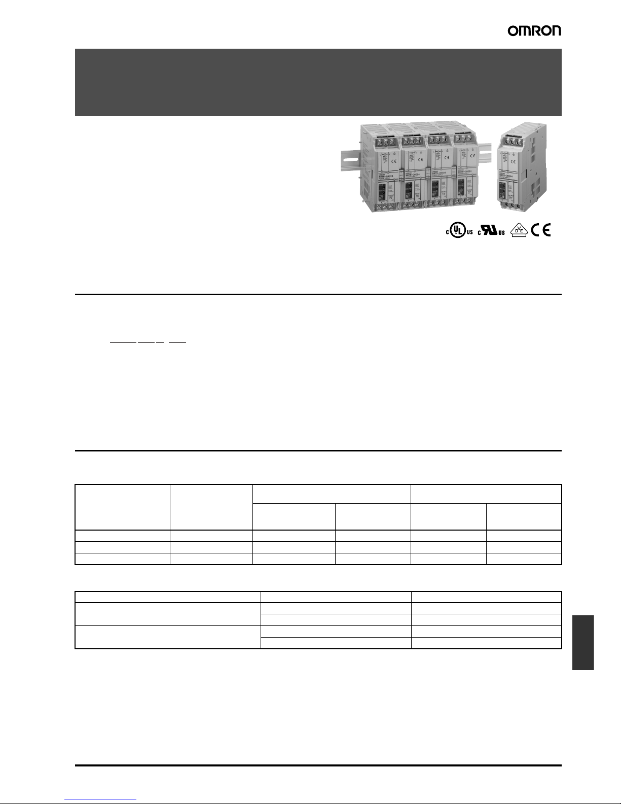
S8TS
Block-type Switch mode Power Supply That
Mounts to DIN Track
• Power supply range of 60 to 240 W available with just one model
(24-V models).
• Easy creation of multi-power supply configurations with different
output power supplies connected together (24-V, 12-V, and 5-V
models).
• Improve power supply system reliability by creating N+1 redundant systems (24-V and 12-V models).
• Approved by UL/CSA standards, EN60950 (IEC 950), and VDE
0160.
Model Number Structure
■ Model Number Legend
Ordering Information
■ Basic Block
■ Bus Line Connector
Note 1. One S8T-BUS01 Connector and one S8T-BUS02 Connector are included as accessories.
2. Bus Line Connectors are ordered separately if necessary.
3. Attached connectors: 2ESDPLM-05P (for output terminal) and 3ESDPLM-03P (for input terminal) made by DINKLE ENTERPRISE.
4. One package contains 10 S8T-BUS01 Connectors.
5. One package contains 10 S8T-BUS02 Connectors.
1 2 3 4
S8TS-@@@@@@-@@
1. Capacity 2. Output Voltage 3. Structure 4. Bus Line Connectors
060: 60 W
030: 30 W
025: 25 W
24: 24 V
12: 12 V
05: 5 V
None: Screw terminals
F: Connector
terminals
None: Basic Block only
E1: S8T-BUS01 and
S8T-BUS02
included
Output voltage Output current Screw terminal type Connector terminal type
(See note 3.)
With Bus Line
Connectors
(See note 1.)
Without Bus Line
Connectors
(See note 2.)
With Bus Line
Connectors
(See note 1.)
Without Bus Line
Connectors
(See note 2.)
24 V 2.5 A S8TS-06024-E1 S8TS-06024 S8TS-06024F-E1 S8TS-06024F
12 V 2.5 A S8TS-03012-E1 S8TS-03012 S8TS-03012F-E1 S8TS-03012F
5 V 5 A --- S8TS-02505 --- S8TS-02505F
Type Number of Connectors Model number
AC line + DC line bus
(For parallel operation)
1 Connector S8T-BUS01
10 Connectors (See note 4.) S8T-BUS11
AC line bus
(For series operation or isolated operation)
1 Connector S8T-BUS02
10 Connectors (See note 5.) S8T-BUS12
Page 2
L-26 Switch Mode Power Supply S8TS
Specifications
■ Ratings/Characteristics
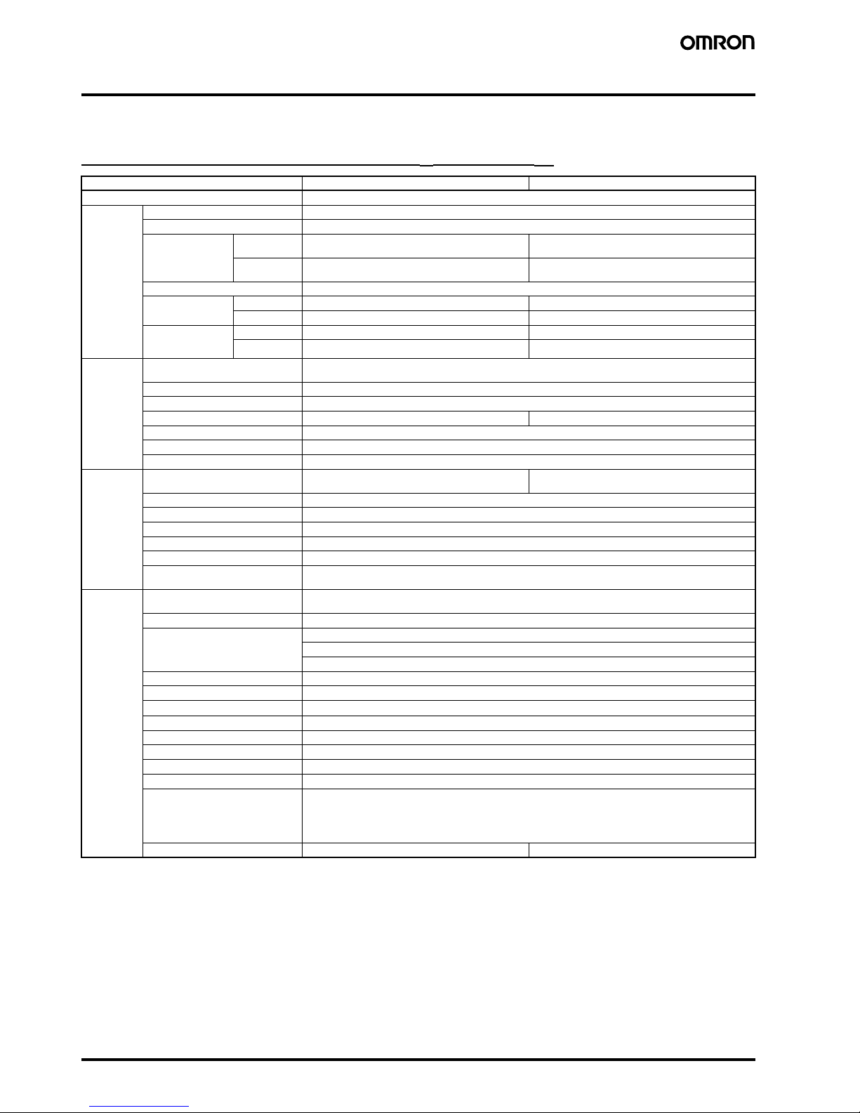
24/12-V Models (Basic Block: S8TS-06024@/S8TS-03012@)
Note 1. Refer to page 31 for details on adjusting the output voltage for parallel operation. If set to less than −10%, the undervoltage detection func-
tion may operate. Ensure that the output capacity and output current after adjustment do not exceed the rated output capacity and rated
output current respectively.
2. Class 2 approval does not apply to parallel operation.
3. The output current is specified at power output terminals.
4. Refer to the explanations of functions on page 28 for details.
5. Be sure to mount End Plates (PFP-M) on both ends of the Power Supply.
Item Single operation Parallel operation
Efficiency 24-V models: 75% min.; 12-V models: 70% min. (with rated input, 100% load)
Input Voltage 100 to 240 VAC (85 to 264 VAC)
Frequency 50/60 Hz (47 to 63 Hz)
Current 100 V input 24-V models: 1.0 A max.
12-V models: 0.7 A max.
24-V models: 1.0 A × (No. of Blocks) max.
12-V models: 0.7 A × (No. of Blocks) max.
200 V input 24-V models: 0.5 A max.
12-V models: 0.4 A max.
24-V models: 0.5 A × (No. of Blocks) max.
12-V models: 0.4 A × (No. of Blocks) max.
Power factor 24-V models: 0.9 min.; 12-V models: 0.8 min. (with rated input, 100% load) (See note 3.)
Leakage current 100 V input 0.35 mA max. 0.35 mA × (No. of Blocks) max.
240 V input 0.7 mA max. 0.7 mA × (No. of Blocks) max.
Inrush current
(25°C, cold start)
(See note 4.)
100 V input 25 A max. 25 A × (No. of Blocks) max.
200 V input 50 A max. 50 A × (No. of Blocks) max.
Output (See
note 3.)
Voltage adjustment range 24-V models: 22 to 28 V
12-V models: 12 V ±10% (with V.ADJ) (See note 1.)
Ripple 2% (p-p) max.
Input variation influence 0.5% max. (with 85 to 264 VAC input, 100% load)
Load variation influence 2% max. (with rated input, 10% to 100% load) 3% max. (with rated input, 10% to 100% load)
Temperature variation influence 0.05%/°C max. (with rated input and output)
Startup time (See note 4.) 1,000 ms max.
Hold time (See note 4.) 20 ms min. (with 100/200 VAC, rated input)
Additional
functions
Overcurrent protection (See note 4.) 105% to 125% of rated load current, inverted L drop
type, automatic reset
100% to 125% of rated load current inverted L drop
type, automatic reset
Overvoltage protection (See note 4.) Yes
Parallel operation Yes, 4 Blocks max.
N+1 redundant system Yes, 5 Blocks max.
Series operation Yes
Undervoltage indicator (See note 4.) Yes (color: red)
Undervoltage detection output (See
note 4.)
Yes (open collector output), 30 VDC max., 50 mA max.
Other Ambient operating temperature (See
note 4.)
Operating: Refer to the derating curve in Engineering Data.
Storage: −25 to 65°C (with no icing or condensation)
Ambient humidity Operating: 25% to 85%; Storage: 25% to 90%
Dielectric strength 3.0 kVAC, 50/60 Hz for 1 minute (between all inputs and all outputs; detection current: 20 mA)
2.0 kVAC, 50/60 Hz for 1 minute (between all inputs and GR terminal; detection current: 20 mA)
1.0 kVAC for 1 minute (between all outputs and GR terminal; detection current: 20 mA)
Insulation resistance 100 MΩ min. (between all outputs and all inputs, and between all outputs and GR terminal) at 500 VDC
Vibration resistance 10 to 55 Hz, 0.375-mm single amplitude for 2 h each in X, Y, and Z directions
Shock resistance
150 m/s
2
, 3 times each in ±X, ±Y, and ±Z directions
Output indicator Yes (color: green)
Electromagnetic interference Conforms to FCC Class A, EN50081-1
EMI Conforms to EN50081-1/1992
Power factor correction Conforms to EN61000-3-2, EN61000-3-2 A14
EMS Conforms to EN61000-6-2/1999
Approved standards UL: 508 (Listing; Class 2: Per UL1310), 1950, 1604 (Class I, Division 2, Groups A, B, C, D
Hazardous Locations))
cUL: CSA C22.2 No.14, No.213 (Class I, Division 2, Groups A, B, C, D
Hazardous Locations), No. 950 (Class 2) (See note 2.)
EN/VDE: EN50178 (=VDE0160), 60950 (=VDE0806)
Weight 450 g max. 450 g × (No. of Blocks) max.
Page 3
Switch Mode Power Supply S8TS L-27
Power
Supplies
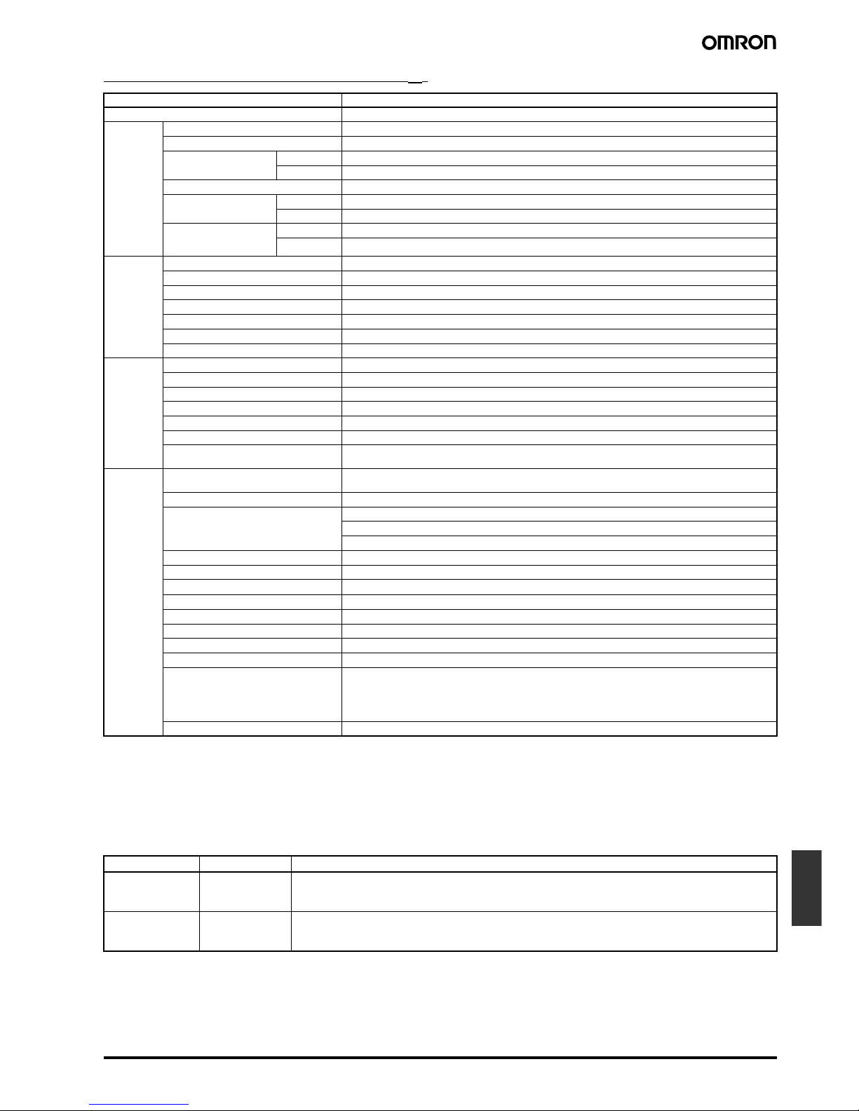
5-V Models (Basic Block: S8TS-02505@)
Note 1. If set to less than −10%, the undervoltage detection function may operate. Ensure that the output capacity and output current after adjust-
ment do not exceed the rated output capacity and rated output current respectively.
2. The output current is specified at power output terminals.
3. Refer to the explanations of functions on page 28 for details.
4. Be sure to mount End Plates (PFP-M) on both ends of the Power Supply.
■ Reference Value
Item Single operation
Efficiency (typical) 62% min. (with rated input, 100% load)
Input Voltage 100 to 240 VAC (85 to 264 VAC)
Frequency 50/60 Hz (47 to 63 Hz)
Current 100 V input 0.7 A max.
200 V input 0.4 A max.
Power factor 0.8 min. (with rated input, 100% load)
Leakage current 100 V input 0.35 mA max.
240 V input 0.7 mA max.
Inrush current
(25°C, cold start)
(See note 2.)
100 V input 25 A max.
200 V input 50 A max.
Output (See
note 2.)
Voltage adjustment range 5 V ± 10% (with V. ADJ) (See note 1.)
Ripple 2% (p-p) max.
Input variation influence 0.5% max. (with 85 to 264 VAC input, 100% load)
Temperature variation influence 0.05%/°C max. (with rated input and output)
Load variation influence 1.5% max. (with rated input, 10% to 100% load)
Startup time (See note 3.) 1,000 ms max.
Hold time (See note 3.) 20 ms min. (with 100/200 VAC, rated input)
Additional
functions
Overcurrent protection (See note 3.) 105% to 125% of rated load current, inverted L drop type, automatic reset
Overvoltage protection (See note 3.) Yes
Parallel operation No
N+1 redundant system No
Series operation Yes (with the external diode)
Undervoltage indicator (See note 3.) Yes (color: red)
Undervoltage detection output (See note
3.)
Yes (open collector output), 30 VDC max., 50 mA max.
Other Ambient operating temperature (See note
3.)
Operating: Refer to the derating curve in Engineering Data.
Storage: −25 to 65°C (with no icing or condensation)
Ambient humidity Operating: 25% to 85%, Storage: 25% to 90%
Dielectric strength 3.0 kVAC, 50/60 Hz for 1 minute (between all inputs and all outputs; detection current: 20 mA)
2.0 kVAC, 50/60 Hz for 1 minute (between all inputs and GR terminal; detection current: 20 mA)
1.0 kVAC for 1 minute (between all outputs and GR terminal; detection current: 20 mA)
Insulation resistance 100 MΩ min. (between all outputs and all inputs, and between all outputs and GR terminal) at 500 VDC
Vibration resistance 10 to 55 Hz, 0.375-mm single amplitude for 2 h each in X, Y, and Z directions
Shock resistance
150 m/s
2
, 3 times each in ±X, ±Y, and ±Z directions
Output indicator Yes (color: green)
Electromagnetic interference Conforms to FCC Class A, EN50081-1
EMI Conforms to EN50081-1/1992
Power factor correction Conforms to EN61000-3-2, EN61000-3-2A14
EMS Conforms to EN61000-6-2/1999
Approved standards UL: 508 (Listing), 1950, 1604 (Class I, Division 2, Groups A, B, C, D
Hazardous Locations)
cUL: CSA C22.2 No.14, No.213 (Class I, Division 2, Groups A, B, C, D
Hazardous Locations), No. 950
EN/VDE: EN50178 (=VDE0160), 60950 (=VDE0806)
Weight 450 g max.
Item Value Definition
Reliability (MTBF) 250,000 hrs min. MTBF stands for Mean Time Between Failures, which is calculated according to the probability of acci-
dental device failures, and indicates reliability of devices. Therefore, it does not necessarily represent the
life of the product.
Life expectancy 10 yrs min. The life expectancy indicates average operating hours under the ambient temperature of 40°C and a load
rate of 50%. Normally this is determined by the life expectancy of the built-in aluminum electrolytic capacitor.
Page 4
L-28 Switch Mode Power Supply S8TS
Connections
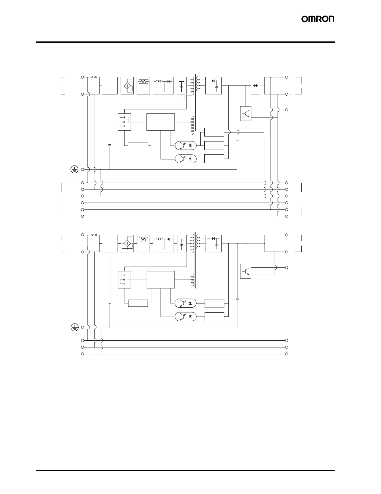
■ Block Diagrams
S8TS-06024@ and S8TS-03012@
S8TS-02505@
AC (N
)
AC (L
)
INP
UT
DC OUTP
UT
DC LOW
OUT
F
use
2.0
A
Noi
se
filt
er
Rectifi
er
Inrush
curre
nt
p
rotection
circuit
Harmoni
c
curre
nt
suppression
circuit
S
moot
h
ing ci
r
cuit
Drive control
circuit
Ocercurrent
detection circuit
Photocoupler
Current
detection circuit
Detection
circuit
Ocervoltage
detection circuit
Protection
diode
Rectifier an
d
smoothin
g
circuit
Undervoltage
indicator/output
Connected to Bus
Line Connector
Connected to Bus
Line Connector
AC(N)
AC(L) +V
−V
INPUT
DC OUTPUT
DC LOW OUT
Rectifier
Photocoupler
Fuse
2.0 A
Noise
filter
Inrush
current
protection
circuit
Harmonic
current
suppression
circuit
Smoothing circuit
Rectifier and
smoothing
circuit
Undervoltage
indicator/output
Drive control
circuit
Detection
circuit
Overvoltage
detection circuit
Overcurrent
detection circuit
Connected to Bus
Line Connector
Connected to Bus
Line Connector
Page 5
Switch Mode Power Supply S8TS L-29
Power
Supplies
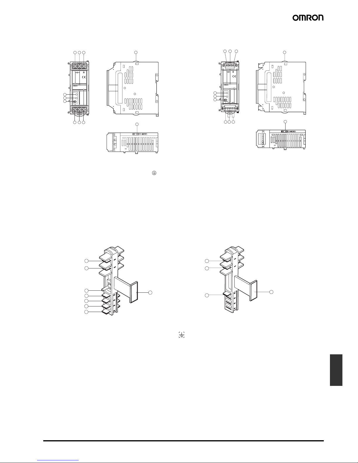
■ Installation
A AC Input Terminal (L): Connect an input line to this terminal.
B AC Input Terminal (N): Connect an input line to this terminal.
C Ground Terminal ( ): Connect a ground line to this terminal.
D Undervoltage Detection Output (DC LOW OUT): Open Collector output
E DC Output Terminal (–V): Connect load lines to this terminal.
F DC Output Terminal (+V): Connect load lines to this terminal.
G Output Indicator (DC ON: Green): Lights while DC output is ON.
H Undervoltage Indicator (DC LOW: Red): Lights when the voltage at the output terminal drops.
I Output Voltage Adjuster (V.ADJ): Use to adjust the voltage.
J Slider: Slide to the lock side when connecting. Unlock the slider when disconnecting.
A AC Input Terminal (L)
B AC Input Terminal (N)
C Ground Terminal ( )
D Parallel Operation Signal Terminal
E DC Output Terminal (+V)
F DC Output Terminal (−V)
G Selector
H Projected Indicator Section
1
7
8
9
4 5 6
2 3
DC ON
DC LOW
DC LOW
V.ADJ
+V
-V
L
LN
N
50/60Hz
AC100
-240V
Class2
Power
Supply
DC24V
2.5A
INPUT
OUTPUT
1.0A
S8TS-06024
POWER SUPPLY
+V-V
10
10
4 5 6
1 2 3
7
8
9
DC ON
DC LOW
DC LOW
V.ADJ
+V
-
V
L
LN
N
50/60Hz
AC100
-240V
Class2
Power
Supply
DC24V
2.5A
INPUT
OUTPUT
1.0A
S8TS-06024F
POWER SUPPLY
+V-V
10
10
Basic Blocks with Screw Terminals: S8TS-@@@@@ Basic Blocks with Connector Terminals: S8TS-@@@@@F
1
8
2
7
3
4
5
6
1
2
3
8
S8T-BUS01 Bus Line Connector
(AC Line + DC Line Bus)
S8T-BUS02 Bus Line Connector
(AC Line Bus)
Page 6

L-30 Switch Mode Power Supply S8TS
Operation
Maximum Number of Blocks That Can
Be Linked
Basic Blocks can be linked using Bus Line Connectors.
Increasing Output Capacity
N+1 Redundant Systems
To ensure stable operation when there is a failure in one of the
Blocks, use within the derating curve for N+1 redundant systems.
Multi-output Power Supply
Up to 4 Basic Blocks with different output voltage specifications can
be linked.
Selecting Bus Line Connectors
Select Bus Line Connectors according to the linking method as follows:
• Using parallel operation:
S8T-BUS01 (DC line connected)
The S8T-BUS01 Bus Line Connector is equipped with a selector to
prevent erroneous connection of Blocks with different output voltage specifications. Slide the selector to the output voltage for parallel operation.
• Not using parallel operation:
S8T-BUS02 (DC line not connected)
Mounting and Removing Bus Line
Connectors
Pay attention to the following points to maintain electrical characteristics.
• Do not insert/remove the Connectors more than 20 times.
• Do not touch the Connector terminals.
• To remove the Connectors, insert a flat-bladed screwdriver alter-
nately at both ends.
Wiring Linked Blocks
When linking Blocks together, wire input lines to one Block only, otherwise inputs may be shorted internally resulting in damage to the
Block.
Do not cross-wire Blocks or wire between a Block and another
device. If the rated current is exceeded, Bus Line Connectors may be
damaged.
When Basic Blocks are linked together, it is necessary to wire the GR
terminal of only one Block, not all the Blocks.
Series Operation and ± Output
Using 2 Basic Blocks enables series operation and the use of
± output. An external diode is not required for S8TS-06024@ and
S8TS-03012@ models but is required for S8TS-02505@ models. Use
the following as a rough guide for selecting the diode.
Note: Series operation is possible with different specifications, but the
current that flows to the load must not exceed the rated output
current of any Block.
Models Number of Blocks N+1 Redundant
System
S8TS-06024@ 4 Blocks Yes, 5 Blocks
S8TS-03012@ 4 Blocks Yes, 5 Blocks
S8TS-02505@ No No
24V
12V
Selector
LLNNGR GR
−V+V −V+V
LLNNGR GR
−V+V −V+V
S8T-BUS01 S8T-BUS02
AC Line
DC Line
DC line connected
(parallel connection)
DC line not connected
(isolated connection)
Type Schottky barrier diode
Withstand voltage
(V
RRM
)
At least twice the rated output voltage
Current with normal direction (I
F
)
At least twice the rated output current
L
N
L
N
−V
+V
Do not wire inputs to more than one
L
N
L
N
L
N
Do not use cross-wire Blocks.
Page 7

Switch Mode Power Supply S8TS L-31
Power
Supplies
Adjusting Output Voltage for Parallel
Operation
The Blocks are factory-set to the rated output voltage. When adjusting voltages, set the same values for Blocks with V.ADJ before linking
them together. Adjust the set values within the limits given in the following table.
Do not adjust voltages after Blocks are linked together. The output
voltage may become unstable.
Inrush Current
The inrush current per Basic Block is 25 A max. at 100 VAC and 50 A
max. at 200 VAC. When N Blocks are linked together, the inrush current will be equal to N times that for 1 Basic Block. Be sure to use a
fuse with the appropriate fusing characteristics or a breaker with the
appropriate tripping characteristics.
Leakage Current
The leakage current per Basic Block is 0.35 mA at 100 VAC and
0.7 mA at 240 VAC. When N Blocks are linked together, the leakage
current will be equal to N times that for 1 Basic Block.
Mounting
Mounting Direction
Use standard mounting only. Using any other mounting method will
prevent proper hear dissipation and may result in deterioration or
damage of internal elements.
Model number Difference between output
voltages
S8TS-06024@ 0.24 V max.
S8TS-03012@ 0.12 V max.
L
N
L
N
L
N
L
N
S8T
-BUS02
S8T
-BUS02
Series Operation ± Output
Load Load Load Load Load Load
24/12-V models 5-V models 24/12-V models 5-V models
Standard mounting Yes
Face-up mounting No
Other mounting methods No
Standard mounting
Face-up mounting
Page 8

L-32 Switch Mode Power Supply S8TS
Engineering Data
■ Derating Curves
Note: If there is a derating problem, use forced air-cooling.
The ambient temperature is specified for a point 50 mm below the power supply.
■ Overload Protection
The Power Supply is provided with an overload protection function
that protects the load and the power supply from possible damage by
overcurrent. When the output current rises above 105% min. of the
rated current (100% min. of the rated current for parallel operation),
the protection function is triggered, decreasing the output voltage.
When the output current falls within the rated range, the overload
protection function is automatically cleared.
Note: Do not allow the short-circuited or overcurrent state to continue
for more than 20 s, otherwise it may damage the element.
■ Overvoltage Protection
The Power Supply is provided with an overvoltage protection function
that protects the load and the Power Supply from possible damage
by overvoltage. When an excessive voltage is output, the output voltage is shut OFF. Reset the Power Supply by turning it OFF for at
least 1 minute and then turning it back ON again.
24-V Models
12-V and 5-V Models
Note: Do not turn ON the power again until the cause of the overvolt-
age has been removed.
−20 −10 0 10 20 30 40 50 55 60 70
120
100
80
60
40
20
0
−20 −10 0 10 20 30 40 50 60 70
120
100
80
60
40
20
0
−20 −10 0 10 20 30 40 50 60 70
120
100
80
60
40
20
0
20 mm min.
N+1 Redundant System
Parallel Operation and Side-by-side
Mounting
Single Operation with Spaces
between Blocks
Ambient temperature (˚C)
200 V input (side-by-side mounting)
Ambient temperature (˚C)
200 V input
100 V input
Load (%)
100/200-V input
(parallel operation),
100-V input (sideby-side mounting)
Load (%)
Ambient temperature (˚C)
Load (%)
0 50 100
Output current (%)
Output voltage (V)
0 V
28 V
22 V
Variable range
Rated output
voltage
Overvoltage
protection
operating
Output voltage (V)
0 V
+10%
–10%
Variable range
Overvoltage
protection
operating
Rated output
voltage
Output voltage (V)
Page 9

Switch Mode Power Supply S8TS L-33
Power
Supplies
■ Inrush Current, Startup Time,
Hold Time
■ Undervoltage Indicator and
Undervoltage Detection Output
When a drop in the output voltage is detected, the red indicator (DC
LOW) lights and transistor (DC LOW: OUT) output turns ON. The
detection voltage is set to approximately 80% (75% to 90%) of the
rated output voltage.
This function monitors the voltage at the output terminals. For accurate confirmation of the output status, measure the voltage at the
output terminal.
Note 1: Transistor output:Open collector
30 VDC max., 50 mA max.
ON residual voltage: 2 V max.
OFF leakage current: 0.1 mA max.
2: The indicators become dimmer as the output voltage ap-
proaches 0 V.
Undervoltage Output
90%
96.5%
Input ON Input OFF
Hold time (20 ms min.)
Inrush current on input application
Startup time
(1,000 ms max.)
Output
voltage
AC input
current
AC input
voltage
Status of indicator Voltage status Output
status
(See note 1.)
Higher than approx. 80% of the
rated output
voltage
ON
Less than approx. 80% of the
rated output
voltage
OFF
Close to 0 V OFF
DC ON
DC LOW
Green:
Red:
DC ON
DC LOW
Green:
Red:
(See
note 2.)
DC ON
DC LOW
Green:
Red:
+V−V
+V−V
DC LOW OUT DC LOW OUT
Blocks with Screw Terminals Blocks with Connector Terminals
Page 10

L-34 Switch Mode Power Supply S8TS
Dimensions
Note: All units are in millimeters unless otherwise indicted.
■ Mounting Track (Order Separately)
DIN Track
4
5
10
DC ON
DC LOW
DC LOW
V.ADJ
+V
-V
L
LN
N
50/60Hz
AC100
-240V
Class2
Power
Supply
DC24V
2.5A
INPUT
OUTPUT
1.0A
S8TS-06024
POWER SUPPLY
+V-V
2.5
120
100
43
LOCK
35
120
80.7
4
5.08
5
7.62
LOCK
DC ON
DC LOW
DC LOW
V.ADJ
+V
-V
L
LN
N
50/60Hz
AC100
-240V
Class2
Power
Supply
DC24V
2.5A
INPUT
OUTPUT
1.0A
S8TS-06024F
POWER SUPPLY
+V-V
2.5
80.7
120
35
43
120
S8TS-@@@@@
S8TS-@@@@@F
M4 with square washer
5.6
(Sliding: 15 max.)
5.6
(Sliding: 15 max.)
4.5
15
15(5)*
7.3±
0.15
35±
0.3
27±
0.15
1
10 1025 25 2525
1000(500)*
4.5
151510 1025 25 2525
1000
1 1.5
29.2
16
2427
35±
0.3
PFP-100N2
PFP-100N
PFP-50N
*Values in parentheses
are for the PFP-50N.
Page 11

Switch Mode Power Supply S8TS L-35
Power
Supplies
End Plate
1.3
4.8
35.5
35.5
1.8
1.8
10
6.2
1
50
11.5
10
PFP-M
M4 spring washer
M4×8
pan-head
screw
Page 12

L-36 Switch Mode Power Supply S8TS
Precautions
!WARNING
Do not attempt to take any Block apart or touch the interior of a
Block while the power is being supplied. Doing so may result in
electric shock.
Do not link or separate any Blocks while the power is being supplied. Doing so may result in electric shock.
Do not remove the connector cover on unused Bus Line Connectors. Doing so may result in electric shock.
Close the terminal covers before use. Not doing so may result in
electric shock.
!Caution
When linking Blocks, lock the sliders and track stoppers.
When linking Blocks, wire the input line for 1 Block only. Otherwise, inputs may be shorted internally resulting in damage to the
Blocks.
The tightening torque for terminal screws is 1.08 N·m. The tightening torque for connector screws and screw flanges is 0.30 N·m.
Loose screws may result in fire.
Do not touch the Power Supply while power is supplied or immediately after power is turned OFF. The Power Supply becomes hot
and touching it may result in injury.
Mounting
To improve the long-term reliability of devices, give due consideration
to heat dissipation when mounting. With the S8TS, heat is dissipated
by natural convection. Mount Blocks in a way that allows convection
in the atmosphere around them.
*1. Convection of air
*2. 75 mm min.
*3. 75 mm min.
*4. 10 mm min.
When cutting out holes for mounting, make sure that cuttings do not
enter the interior of the products.
Wiring
Be sure to wire I/O terminals correctly. When tightening the terminals, do not exert a force of 100 N or more on terminal blocks or connector terminals.
With Blocks with connector terminals, the current for 1 terminal must
not exceed 7.5 A. If a higher current is required, use 2 terminals.
Recommended Wire Size for Single
Operation
Recommended Wire Size for Parallel
Operation
Blocks with Connector Terminals
• When using Blocks with connector terminals, the current for
1 terminal must not exceed 7.5 A. If a higher current is required,
use 2 terminals.
• Do not insert/remove AC input connectors or DC output connector
more than 20 times.
Installation Environment
Do not use the Power Supply in locations subject to shocks or vibrations. Be sure to mount End Plates (PFP-M) on both ends of the
Power Supply. Install the Power Supply well away from any sources
of strong, high-frequency noise.
*1 *1
*1
*4
*1
*2
*3
Model Recommended wire size
S8TS-06024
S8TS-03012
AWG 14 to 20 (cross-sectional area: 0.517
to 2.081 mm
2
)
S8TS-02505 AWG 14 to 18 (cross-sectional area: 0.823
to 2.081 mm
2
)
S8TS-06024F
S8TS-03012F
AWG 12 to 20 (cross-sectional area: 0.517
to 3.309 mm
2
)
S8TS-02505F AWG 12 to 18 (cross-sectional area: 0.823
to 3.309 mm
2
)
Model Recommended wire size
S8TS-06024
S8TS-03012
For 2 Units connected in parallel
AWG 14 to 18 (cross-sectional area: 0.823 to 2.081 mm
2
)
For 3 Units connected in parallel
AWG 14 to 16 (cross-sectional area: 1.309 to 2.081 mm
2
)
For 4 Units connected in parallel
AWG 14 (cross-sectional area:
2.081 mm
2
)
S8TS-06024F
S8TS-03012F
For 2 Units connected in parallel
AWG 12 to 18 (cross-sectional area: 0.823 to 3.309 mm
2
)
For 3 Units connected in parallel
AWG 12 to 16 (cross-sectional area: 1.309 to 3.309 mm
2
)
For 4 Units connected in parallel
AWG 12 to 14 (cross-sectional area: 2.081 to 3.309 mm
2
)
Page 13

Switch Mode Power Supply S8TS L-37
Power
Supplies
Operating and Storage Environments
Do not use or store the Power Supply in the following locations.
Doing so may result in failure, malfunction, or deterioration of performance characteristics.
• Do not use in locations subject to direct sunlight.
• Do not use in locations where the ambient temperature exceeds
the range of the derating curve.
• Do not use in locations where the humidity is outside the range
25% to 85%, or locations subject to condensation due to sudden
temperature changes.
• Do not store in locations where the ambient temperature is outside
the range –25 to 65°C or where the humidity is outside the range
25% to 95%.
• Do not use in locations where liquids, foreign matter, corrosive
gases, or flammable gases may enter the interior of products.
Charging Batteries
If a battery is connected as the load, provide an overcurrent control
circuit and an overvoltage protective circuit.
Output Voltage Adjuster (V.ADJ)
Do not exert excessive force on the output voltage adjuster (V.ADJ).
Doing so may break the adjuster.
Setting the adjuster to a setting less than 10% may cause the undervoltage detection function to operate.
Bus Line Connectors
Do not apply sudden shocks (e.g., by dropping) to the Bus Line Connectors. Doing so may result in damage.
DIN Track Mounting
To mount the Block on a DIN track, hook portion (A) of the Block onto
the track and press the Block in direction (B).
To dismount the Block, pull down portion (C) with a flat-blade screwdriver and pull out the Block.
No Output Voltage
If there is no output voltage, it is possible that overcurrent protection
or overvoltage protection is operating. It is also possible that the latch
protection circuit is operating due to the application of a large surge,
such as lightning surge. Confirm the 2 points below. If there is still no
output voltage, consult your OMRON representative.
• Checking for Overcurrent Protection:
Separate the load line and confirm that it is not in an overcurrent
state (including short-circuits).
• Checking for Overvoltage Protection or Latch Protection:
Turn the input power supply OFF, and then turn it ON again after 1
minute or more has elapsed.
B
A
C
30 mm min.
Track stopper
Page 14

L-38 Switch Mode Power Supply S8TS
In the interest of product improvement, specifications are subject to change without notice.
ALL DIMENSIONS SHOWN ARE IN MILLIMETERS.
To convert millimeters into inches, multiply by 0.03937. To convert grams into ounces, multiply by 0.03527.
Cat. No. T022-E1-03
 Loading...