


CJ1W-NC471
Table of contents
 Loading...
Omron CJ1W-NC471, S1W-NCF71, CS1W-NC271, CJ1W-NCF71, CJ1W-NC271 OPERATION MANUAL
...
Cat. No.W426-E1-09
SYSMAC
CJ1W-NC271/NC471/
NCF71/NCF71-MA
CS1W-NC271/NC471/NCF71
Position Control Units
OPERATION MANUAL

CJ1W-NC271/NC471/NCF71/NCF71-MA CS1W-NC271/NC471/NCF71 Position Control Units
Operation Manual
Revised October 2008

iv

Notice:
r
f
OMRON products are manufactured for use according to proper procedures by a qualified operator
and only for the purposes described in this manual.
The following conventions are used to indicate and classify precautions in this manual. Always heed
the information provided with them. Failure to heed precautions can result in injury to people or damage to property.
!DANGER Indicates an imminently hazardous situation which, if not avoided, will result in death or
serious injury. Additionally, there may be severe property damage.
!WARNING Indicates a potentially hazardous situation which, if not avoided, could result in death or
serious injury. Additionally, there may be severe property damage.
!Caution Indicates a potentially hazardous situation which, if not avoided, may result in minor or
moderate injury, or property damage.
OMRON Product References
All OMRON products are capitalized in this manual. The word “Unit” is also capitalized when it refers to
an OMRON product, regardless of whether or not it appears in the proper name of the product.
The abbreviation “Ch,” which appears in some displays and on some OMRON products, often means
“word” and is abbreviated “Wd” in documentation in this sense.
The abbreviation “PLC” means Programmable Controller. “PC” is used, however, in some Programming Device displays to mean Programmable Controller.
Visual Aids
The following headings appear in the left column of the manual to help you locate different types of
information.
OMRON, 2004
All rights reserved. No part of this publication may be reproduced, stored in a retrieval system, or transmitted, in any form, o
by any means, mechanical, electronic, photocopying, recording, or otherwise, without the prior written permission o
OMRON.
No patent liability is assumed with respect to the use of the information contained herein. Moreover, because OMRON is constantly striving to improve its high-quality products, the information contained in this manual is subject to change without
notice. Every precaution has been taken in the preparation of this manual. Nevertheless, OMRON assumes no responsibility
for errors or omissions. Neither is any liability assumed for damages resulting from the use of the information contained in
this publication.
Note Indicates information of particular interest for efficient and convenient opera-
tion of the product.
1,2,3... 1. Indicates lists of one sort or another, such as procedures, checklists, etc.
v

vi

TABLE OF CONTENTS
PRECAUTIONS . . . . . . . . . . . . . . . . . . . . . . . . . . . . . . . . . . . xxiii
1 Intended Audience. . . . . . . . . . . . . . . . . . . . . . . . . . . . . . . . . . . . . . . . . . . . . . . . . . . . . . . . . xxiv
2 General Precautions. . . . . . . . . . . . . . . . . . . . . . . . . . . . . . . . . . . . . . . . . . . . . . . . . . . . . . . . xxiv
3 Safety Precautions . . . . . . . . . . . . . . . . . . . . . . . . . . . . . . . . . . . . . . . . . . . . . . . . . . . . . . . . . xxiv
4 Operating Environment Precautions . . . . . . . . . . . . . . . . . . . . . . . . . . . . . . . . . . . . . . . . . . . xxv
5 Application Precautions. . . . . . . . . . . . . . . . . . . . . . . . . . . . . . . . . . . . . . . . . . . . . . . . . . . . . xxvi
6 Conformance to EC Directives . . . . . . . . . . . . . . . . . . . . . . . . . . . . . . . . . . . . . . . . . . . . . . . xxviii
SECTION 1
Features and System Configuration . . . . . . . . . . . . . . . . . . . 1
1-1 Features . . . . . . . . . . . . . . . . . . . . . . . . . . . . . . . . . . . . . . . . . . . . . . . . . . . . . . . . . . . . . . . . . 2
1-2 System Configuration . . . . . . . . . . . . . . . . . . . . . . . . . . . . . . . . . . . . . . . . . . . . . . . . . . . . . . 3
1-3 Basic Operations . . . . . . . . . . . . . . . . . . . . . . . . . . . . . . . . . . . . . . . . . . . . . . . . . . . . . . . . . . 4
1-4 List of Functions and Specifications . . . . . . . . . . . . . . . . . . . . . . . . . . . . . . . . . . . . . . . . . . . 6
1-5 List of Functions by Purpose. . . . . . . . . . . . . . . . . . . . . . . . . . . . . . . . . . . . . . . . . . . . . . . . .8
1-6 Comparison with Existing Models . . . . . . . . . . . . . . . . . . . . . . . . . . . . . . . . . . . . . . . . . . . . 9
SECTION 2
Basic Procedures . . . . . . . . . . . . . . . . . . . . . . . . . . . . . . . . . . . 11
2-1 Basic Flow of Operations . . . . . . . . . . . . . . . . . . . . . . . . . . . . . . . . . . . . . . . . . . . . . . . . . . .12
2-2 Starting Operation . . . . . . . . . . . . . . . . . . . . . . . . . . . . . . . . . . . . . . . . . . . . . . . . . . . . . . . . . 16
SECTION 3
Installation and Wiring . . . . . . . . . . . . . . . . . . . . . . . . . . . . . 31
3-1 Nomenclature and Functions. . . . . . . . . . . . . . . . . . . . . . . . . . . . . . . . . . . . . . . . . . . . . . . . . 32
3-2 Installing the Position Control Unit. . . . . . . . . . . . . . . . . . . . . . . . . . . . . . . . . . . . . . . . . . . . 35
3-3 External I/O Circuits . . . . . . . . . . . . . . . . . . . . . . . . . . . . . . . . . . . . . . . . . . . . . . . . . . . . . . . 39
3-4 Wiring . . . . . . . . . . . . . . . . . . . . . . . . . . . . . . . . . . . . . . . . . . . . . . . . . . . . . . . . . . . . . . . . . . 53
SECTION 4
Data Areas . . . . . . . . . . . . . . . . . . . . . . . . . . . . . . . . . . . . . . . . 71
4-1 Overall Structure . . . . . . . . . . . . . . . . . . . . . . . . . . . . . . . . . . . . . . . . . . . . . . . . . . . . . . . . . . 72
4-2 Data Areas . . . . . . . . . . . . . . . . . . . . . . . . . . . . . . . . . . . . . . . . . . . . . . . . . . . . . . . . . . . . . . . 75
4-3 Common Parameter Area . . . . . . . . . . . . . . . . . . . . . . . . . . . . . . . . . . . . . . . . . . . . . . . . . . . 92
4-4 Axis Parameter Area . . . . . . . . . . . . . . . . . . . . . . . . . . . . . . . . . . . . . . . . . . . . . . . . . . . . . . . 97
4-5 Servo Parameter Area . . . . . . . . . . . . . . . . . . . . . . . . . . . . . . . . . . . . . . . . . . . . . . . . . . . . . . 100
4-6 Common Operating Memory Area . . . . . . . . . . . . . . . . . . . . . . . . . . . . . . . . . . . . . . . . . . . . 164
4-7 Axis Operating Output Memory Areas . . . . . . . . . . . . . . . . . . . . . . . . . . . . . . . . . . . . . . . . . 170
4-8 Axis Operating Input Memory Areas . . . . . . . . . . . . . . . . . . . . . . . . . . . . . . . . . . . . . . . . . . 179
vii

TABLE OF CONTENTS
SECTION 5
Transferring and Saving Data . . . . . . . . . . . . . . . . . . . . . . . . 201
5-1 Transferring Data. . . . . . . . . . . . . . . . . . . . . . . . . . . . . . . . . . . . . . . . . . . . . . . . . . . . . . . . . . 202
5-2 Transferring PCU Parameters . . . . . . . . . . . . . . . . . . . . . . . . . . . . . . . . . . . . . . . . . . . . . . . . 204
5-3 Transferring Servo Parameters . . . . . . . . . . . . . . . . . . . . . . . . . . . . . . . . . . . . . . . . . . . . . . . 210
SECTION 6
MECHATROLINK . . . . . . . . . . . . . . . . . . . . . . . . . . . . . . . . 221
6-1 MECHATROLINK Overview . . . . . . . . . . . . . . . . . . . . . . . . . . . . . . . . . . . . . . . . . . . . . . . . 222
6-2 MECHATROLINK Settings . . . . . . . . . . . . . . . . . . . . . . . . . . . . . . . . . . . . . . . . . . . . . . . . . 223
6-3 MECHATROLINK Communications Control . . . . . . . . . . . . . . . . . . . . . . . . . . . . . . . . . . . 232
6-4 Standard Settings for Servo Drives Using MECHATROLINK. . . . . . . . . . . . . . . . . . . . . . . 247
SECTION 7
Position Control Structure . . . . . . . . . . . . . . . . . . . . . . . . . . . 255
7-1 PCU Control System . . . . . . . . . . . . . . . . . . . . . . . . . . . . . . . . . . . . . . . . . . . . . . . . . . . . . . . 256
7-2 Control Units . . . . . . . . . . . . . . . . . . . . . . . . . . . . . . . . . . . . . . . . . . . . . . . . . . . . . . . . . . . . . 257
7-3 Coordinate System and Present Position. . . . . . . . . . . . . . . . . . . . . . . . . . . . . . . . . . . . . . . . 260
7-4 Acceleration and Deceleration Operations . . . . . . . . . . . . . . . . . . . . . . . . . . . . . . . . . . . . . . 261
7-5 Limit Input Operations . . . . . . . . . . . . . . . . . . . . . . . . . . . . . . . . . . . . . . . . . . . . . . . . . . . . . 270
SECTION 8
Defining the Origin . . . . . . . . . . . . . . . . . . . . . . . . . . . . . . . . . 273
8-1 Overview . . . . . . . . . . . . . . . . . . . . . . . . . . . . . . . . . . . . . . . . . . . . . . . . . . . . . . . . . . . . . . . . 274
8-2 Origin Search Operation . . . . . . . . . . . . . . . . . . . . . . . . . . . . . . . . . . . . . . . . . . . . . . . . . . . . 275
8-3 Present Position Preset. . . . . . . . . . . . . . . . . . . . . . . . . . . . . . . . . . . . . . . . . . . . . . . . . . . . . . 296
8-4 Origin Return. . . . . . . . . . . . . . . . . . . . . . . . . . . . . . . . . . . . . . . . . . . . . . . . . . . . . . . . . . . . . 298
8-5 Phase Z Margin . . . . . . . . . . . . . . . . . . . . . . . . . . . . . . . . . . . . . . . . . . . . . . . . . . . . . . . . . . . 303
8-6 Absolute Encoder Origin. . . . . . . . . . . . . . . . . . . . . . . . . . . . . . . . . . . . . . . . . . . . . . . . . . . .305
SECTION 9
Positioning . . . . . . . . . . . . . . . . . . . . . . . . . . . . . . . . . . . . . . . . 317
9-1 Direct Operation Overview . . . . . . . . . . . . . . . . . . . . . . . . . . . . . . . . . . . . . . . . . . . . . . . . . .318
9-2 Direct Operation Procedure. . . . . . . . . . . . . . . . . . . . . . . . . . . . . . . . . . . . . . . . . . . . . . . . . .319
9-3 PCU Data Settings for Direct Operation . . . . . . . . . . . . . . . . . . . . . . . . . . . . . . . . . . . . . . . . 319
9-4 Using Direct Operation . . . . . . . . . . . . . . . . . . . . . . . . . . . . . . . . . . . . . . . . . . . . . . . . . . . . . 323
9-5 Interrupt Feeding . . . . . . . . . . . . . . . . . . . . . . . . . . . . . . . . . . . . . . . . . . . . . . . . . . . . . . . . . . 331
9-6 Torque Limit Function. . . . . . . . . . . . . . . . . . . . . . . . . . . . . . . . . . . . . . . . . . . . . . . . . . . . . . 334
9-7 Linear Interpolation . . . . . . . . . . . . . . . . . . . . . . . . . . . . . . . . . . . . . . . . . . . . . . . . . . . . . . . . 335
viii

TABLE OF CONTENTS
SECTION 10
Other Operations . . . . . . . . . . . . . . . . . . . . . . . . . . . . . . . . . . 349
10-1 Servo Lock/Unlock . . . . . . . . . . . . . . . . . . . . . . . . . . . . . . . . . . . . . . . . . . . . . . . . . . . . . . . . 350
10-2 Jogging. . . . . . . . . . . . . . . . . . . . . . . . . . . . . . . . . . . . . . . . . . . . . . . . . . . . . . . . . . . . . . . . . . 351
10-3 Override . . . . . . . . . . . . . . . . . . . . . . . . . . . . . . . . . . . . . . . . . . . . . . . . . . . . . . . . . . . . . . . . . 355
10-4 Torque Limits. . . . . . . . . . . . . . . . . . . . . . . . . . . . . . . . . . . . . . . . . . . . . . . . . . . . . . . . . . . . . 357
10-5 Speed Control . . . . . . . . . . . . . . . . . . . . . . . . . . . . . . . . . . . . . . . . . . . . . . . . . . . . . . . . . . . . 364
10-6 Torque Control. . . . . . . . . . . . . . . . . . . . . . . . . . . . . . . . . . . . . . . . . . . . . . . . . . . . . . . . . . . . 375
10-7 Backlash Compensation. . . . . . . . . . . . . . . . . . . . . . . . . . . . . . . . . . . . . . . . . . . . . . . . . . . . . 381
10-8 Software Limits . . . . . . . . . . . . . . . . . . . . . . . . . . . . . . . . . . . . . . . . . . . . . . . . . . . . . . . . . . . 383
10-9 Stop Functions . . . . . . . . . . . . . . . . . . . . . . . . . . . . . . . . . . . . . . . . . . . . . . . . . . . . . . . . . . . . 388
10-10 DEVIATION COUNTER RESET. . . . . . . . . . . . . . . . . . . . . . . . . . . . . . . . . . . . . . . . . . . . . 393
SECTION 11
Sample Programs . . . . . . . . . . . . . . . . . . . . . . . . . . . . . . . . . . 397
11-1 Overview . . . . . . . . . . . . . . . . . . . . . . . . . . . . . . . . . . . . . . . . . . . . . . . . . . . . . . . . . . . . . . . . 398
11-2 Basic Program Examples. . . . . . . . . . . . . . . . . . . . . . . . . . . . . . . . . . . . . . . . . . . . . . . . . . . .399
11-3 Application Examples . . . . . . . . . . . . . . . . . . . . . . . . . . . . . . . . . . . . . . . . . . . . . . . . . . . . . . 424
SECTION 12
Troubleshooting . . . . . . . . . . . . . . . . . . . . . . . . . . . . . . . . . . . 455
12-1 Overview of PCU Errors . . . . . . . . . . . . . . . . . . . . . . . . . . . . . . . . . . . . . . . . . . . . . . . . . . . . 456
12-2 Troubleshooting Procedure . . . . . . . . . . . . . . . . . . . . . . . . . . . . . . . . . . . . . . . . . . . . . . . . . .460
12-3 LED Error Indicators . . . . . . . . . . . . . . . . . . . . . . . . . . . . . . . . . . . . . . . . . . . . . . . . . . . . . . . 461
12-4 Error Codes . . . . . . . . . . . . . . . . . . . . . . . . . . . . . . . . . . . . . . . . . . . . . . . . . . . . . . . . . . . . . . 464
12-5 Troubleshooting. . . . . . . . . . . . . . . . . . . . . . . . . . . . . . . . . . . . . . . . . . . . . . . . . . . . . . . . . . . 477
12-6 Error Reset. . . . . . . . . . . . . . . . . . . . . . . . . . . . . . . . . . . . . . . . . . . . . . . . . . . . . . . . . . . . . . . 482
12-7 CPU Unit Error Display. . . . . . . . . . . . . . . . . . . . . . . . . . . . . . . . . . . . . . . . . . . . . . . . . . . . . 484
SECTION 13
Maintenance and Inspection . . . . . . . . . . . . . . . . . . . . . . . . . 485
13-1 Inspection. . . . . . . . . . . . . . . . . . . . . . . . . . . . . . . . . . . . . . . . . . . . . . . . . . . . . . . . . . . . . . . . 486
13-2 Inspection Points . . . . . . . . . . . . . . . . . . . . . . . . . . . . . . . . . . . . . . . . . . . . . . . . . . . . . . . . . . 486
13-3 Handling Precautions. . . . . . . . . . . . . . . . . . . . . . . . . . . . . . . . . . . . . . . . . . . . . . . . . . . . . . . 487
13-4 Procedure for Replacing a PCU. . . . . . . . . . . . . . . . . . . . . . . . . . . . . . . . . . . . . . . . . . . . . . . 487
ix

TABLE OF CONTENTS
Appendices
A Performance Characteristics . . . . . . . . . . . . . . . . . . . . . . . . . . . . . . . . . . . . . . . . . . . . . . . . . 491
B List of Parameters . . . . . . . . . . . . . . . . . . . . . . . . . . . . . . . . . . . . . . . . . . . . . . . . . . . . . . . . . 495
C Operation Area I/O Allocations . . . . . . . . . . . . . . . . . . . . . . . . . . . . . . . . . . . . . . . . . . . . . . 559
D List of Error Codes . . . . . . . . . . . . . . . . . . . . . . . . . . . . . . . . . . . . . . . . . . . . . . . . . . . . . . . . 571
E Changing to CS1W/CJ1W-NC271/471/F71 from CS1W/CJ1W-NC113/133/213/233/413/433 579
F Additional Functions for the CJ1W-NCF71-MA . . . . . . . . . . . . . . . . . . . . . . . . . . . . . . . . . 601
Index. . . . . . . . . . . . . . . . . . . . . . . . . . . . . . . . . . . . . . . . . . . . . 605
Revision History . . . . . . . . . . . . . . . . . . . . . . . . . . . . . . . . . . . 615
x

About this Manual:
This manual describes the installation and operation of the CJ1W-NC271/NC471/NCF71/NCF71-MA
and CS1W-NC271/NC471/NCF71 Position Control Units and includes the sections described below.
Please read this manual carefully and be sure you understand the information provided before
attempting to install or operate the Position Control Unit. Be sure to read the precautions provided in
the following section.
Precautions provide general precautions for using the Position Control Unit, Programmable Controller,
and related devices.
Section 1 introduces the features of the Position Control Unit, explains the system configuration in
which it is used, and also provides information on basic operations, functions and specifications.
Section 2 provides an overview of the procedures required to use the Position Control Unit.
Section 3 provides information on nomenclature and functions, and describes the procedures required
for wiring and installation. Information on the MECHATROLINK-II Application Module is also provided.
Section 4 provides an overview of the parameter and data settings used in Position Control Unit operation and provides information on memory allocations.
Section 5 explains how to transfer and save parameters and data using the data transfer bits.
Section 6 provides an overview of MECHATROLINK communications, and includes information on
settings and procedures required to use MECHATROLINK with the Position Control Unit.
Section 7 provides an overview of the control system used by the Position Control Unit, including information on the control units, coordinate system, acceleration/deceleration operations, and limit input
operations.
Section 8 provides information on the various operations used to determine the origin, including origin
searches, origin returns, presetting the present position, calculating phase Z margins, and using the
absolute encoder.
Section 9 provides an overview of direct operation and describes the parameter settings, data settings, and procedures required to perform direct operation. Information on interrupt feeding and torque
limits is also provided here.
Section 10 describes the servo lock/unlock, jogging, override, torque limits, speed control, torque control, backlash compensation, software limits, and stop functions.
Section 11 provides basic program examples and application examples for using the Position Control
Unit.
Section 12 provides information on troubleshooting errors that may occur, including details on the
meaning of indicator displays and error codes, and the procedures required to reset errors in the Unit
or axes.
Section 13 describes methods for inspecting and maintaining the Position Control Unit and the procedure required to replace a Position Control Unit.
The Appendices provide information on the performance characteristics, lists of parameters, I/O allocations in the operation areas, lists of error codes, alarm/warning displays, and information required
when changing to the CJ1W-NC271/NC471/NCF71/NCF71-MA or CS1W-NC271/NC471/NCF71 from
a CJ1W/CS1W-NC113/133/213/233/413/433 Position Control Unit.
!WARNING Failure to read and understand the information provided in this manual may result in per-
sonal injury or death, damage to the product, or product failure. Please read each section
in its entirety and be sure you understand the information provided in the section and
related sections before attempting any of the procedures or operations given.
xi
Unit Versions of Position Control Units
Unit Versions A “unit version” has been introduced to manage Position Control Units accord-
ing to differences in functionality accompanying Unit upgrades.
Notation of Unit Versions
on Products
CJ1W-NCF71
N
C
F71
M
LK
R
U
N
E
R
C
E
R
H
E
R
M
D
C
E
B
U
N
F
IT
A
0
9
1
8
No.
2
7
3
6
4
5
M
LK
Confirming Unit Versions
with Support Software
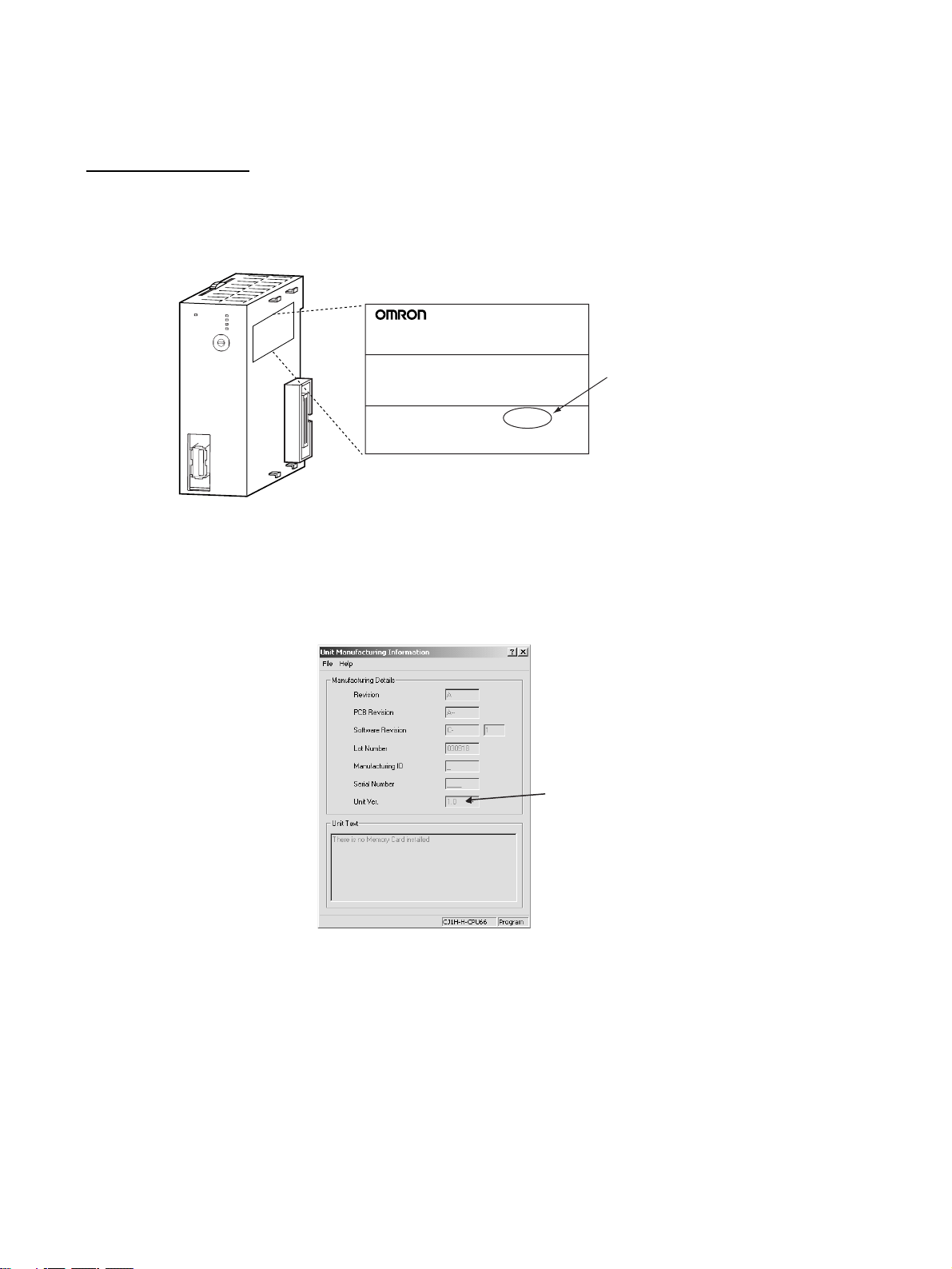
The unit version is given to the right of the lot number on the nameplate of the
products for which unit versions are being managed, as shown below.
Product nameplate
CJ1W-NCF71
NC UNIT
Unit version
Example for unit version 1.0
Lot No. 040401 0000 Ver.1.0
OMRON Corporation MADE IN JAPAN
The unit version of Position Control Units starts with unit version 1.0.
CX-Programmer version 4.0 can be used to confirm the unit version using the
Unit Manufacturing Information.
In the IO Table Window, right-click the Position Control Unit and select Unit
Manufacturing information.
The following Unit Manufacturing information Dialog Box will be displayed.
Unit version
The unit version is displayed as 1.0 in the Unit Version Number field of the
above example. Use the above display to confirm the unit version of the Unit
connected online.
Using Unit Version Label A unit version label is provided with the Position Control Unit. This label can
be attached to the front of the Position Control Unit to differentiate between
Position Control Units with different unit versions.
xii

Functions Supported According to Position Control Unit Versions
Model CJ1W-NC@71/CS1W-NC@71
Unit Ver. 1 .0 Unit Ver. 1.1 Unit Ver. 1.2 Unit Ver. 1.3 Unit Ver. 2. 0 Unit Ver. 2.1
Linear interpolation --- Supported. Supported. Supported. Supported. Supported.
Absolute encoder setup function --- --- Supported. Supported. Supported. Supported.
Deviation counter reset --- --- --- Supported. Supported. Supported.
Establishing connections even
when there are unconnected
axes or axes with alarms that
cannot be cleared
Transferring servo parameters
even when there is an axis error
Creating servo locks during software limit detection when an
absolute encoder is used
Driver main circuit OFF error
detection only when the servo is
locked
Using Holding Area address
H512 and onwards for function
block address allocations
Addition of supported models:
SMARTSTEP Junior Servo
Drives (R7D-ZN@-ML2)
Addition of rejoin function --- --- --- --- Supported. Supported.
Eliminating connection restric-
tion when Servo Drive alarms
occur (enabling connection
when alarm A.C90 occurs)
Addition of origin search operation modes
Addition of origin search preset
function
Faster setting for transfer cycle
and communications cycle
when setting the absolute
encoder PG zero point position
offset with an origin search
--- --- --- Supported. Supported. Supported.
--- --- --- Supported. Supported. Supported.
--- --- --- Supported. Supported. Supported.
--- --- --- Supported. Supported. Supported.
--- --- --- Supported. Supported. Supported.
--- --- --- --- Supported. Supported.
--- --- --- --- Supported. Supported.
--- --- --- --- Supported. Supported.
--- --- --- --- Supported. Supported.
--- --- --- --- --- Supported.
xiii

Upgrades Made According to Unit Versions of the Position Control Unit
Unit Version 1.0 to Unit Version 1.1
Functional upgrade Unit version 1.0 Unit version 1.1
Addition of linear interpolation
function
Linear interpolation cannot be used.
Linear interpolation can be performed for
positioning operations combining one or
more axes.
Linear interpolation can performed for up to
four axes each of axes 1 to 4 and axes 5 to 8
for Servo Drive axes connected to the Position Control Unit. (Refer to 9-7 Linear Inter-
polation.)
Unit Version 1.1 to Unit Version 1.2
Functional upgrade Unit version 1.1 Unit version 1.2
Addition of setup function for
absolute encoders
An absolute encoder must be set up the
first time it is used, when the rotation data
is initialized to 0, or when the absolute
encoder is left for a long period of time
without the battery connected.
With Position Control Units with unit version 1.1 or earlier, the following operation
is used to set up the absolute encoder.
• Special software (personal computer
monitoring software) must be connected
to the Servo Drive to perform the setup
operation.
With Position Control Units with unit version
1.2 or later, the following operation can be
used to set up the absolute encoder.
• Special software (personal computer monitoring software) can be connected to the
Servo Drive to perform the setup operation.
• When the Position Control Unit is used with
a CPU Unit with unit version 3.0 or later, the
absolute encoder can be set up from the
program by using a function block from the
OMRON FB Library.
• The absolute encoder can be set up from
the CX-Motion-NCF. (Refer to 8-6-4
Absolute Encoder Setup.)
Unit Version 1.2 to Unit Version 1.3
Functional upgrade Unit version 1.2 Unit version 1.3
Addition of deviation counter
reset function
The deviation counter in the Servo Drive
cannot be reset from the Position Control
Unit during position control operations.
The deviation counter in the Servo Drive can
be reset from the Position Control Unit during
position control operations.
To deviation reset function in the Position
Control Unit works by sending a movement
command in the opposite direction and of the
same size as the current position deviation
so that the current command position equals
the current feedback position.
(Refer to 10-10 DEVIATION COUNTER
RESET.)
xiv

Functional upgrade Unit version 1.2 Unit version 1.3
Establishing connections
when there are unconnected
axes or axes with alarms that
cannot be cleared
Transferring parameters when
there are axis errors
Locking the servo when a
software limit is being
detected for a Motor with an
absolute encoder
If any of the axes registered in the scan list
are not connected, have the control power
supply interrupted, or have an alarm that
can be reset only by cycling the power
supply, an MLK initialization error (Unit
error code 0020 (hex) will occur after the
connections are established and operations using MECHATROLINK communications will not be possible any axes,
including those without errors.
To start MECHATROLINK communications
normally, all errors must be cleared for all
axes registered in the scan list before connections can be established.
Servo parameters cannot be transferred
(i.e., written, read, or saved) for axes with
errors. The errors must first be reset to
clear the axis error status before Servo
parameters can be transferred.
If an attempt is made to lock the Servo
when an absolute encoder is used, the
software limits are enabled, and the
present position is within the software limit
area, a software limit error will occur and
the Servo lock operation will be canceled.
To lock the Servo in the above situation,
the software limit must first be disabled.
Axis operations using MECHATROLINK communications are possible for any axes registered in the scan list and for which
MECHATROLINK communications have
been started (see note) regardless of
whether there are Servo Drive alarms.
If there are any axes with alarms, they will be
indicated by the Error Flags and error code in
the Axis Operating Input Memory Areas.
If there are alarms in the Servo Drive that can
be cleared only by recycling the power, they
will be detected as Unit errors (MLK initialization errors) for Units with unit version 1.1 or
earlier, but they will be detected in the individual axis areas.
Note If R88D-WN@-ML2 W-series Servo
Drives (Models with Built-in MECHATROLINK-II Communications) are connected, an encoder communications
error (A.C9@) will occur in the Servo
Drive and it will not be possible to start
MECHATROLINK communications for
Units with unit version 1.3 or earlier.
(Refer to 6-3-2 MECHATROLINK Communi-
cations Status.)
Servo parameters can be transferred (i.e.,
written, read, or saved) for axes with errors. If
the axis error already exists, it will not be
overwritten even if an error occurs during
parameter transfer.
If Servo parameters are written when there is
an axis error, be sure to confirm that the
parameters were transferred correctly.
(Refer to 5-3 Transferring Servo Parameters.)
The Servo can be locked at any position,
regardless of the type of encoder and the
software limit settings.
(Refer to 10-8-4 Software Limit Operation.)
xv

Functional upgrade Unit version 1.2 Unit version 1.3
Detecting driver main circuit
OFF errors only when the
Servo is locked
Allocating holding addresses
H512 and higher as function
block addresses
Servo Drive main circuit OFF errors are
detected regardless of whether the Servo
is locked for the axis. Once a Servo Drive
main circuit OFF error is detected, it will
continue to be detected even if the error is
reset until the main circuit power supply is
restored.
The function blocks in the OMRON FB
Library for the Position Control Unit cannot
be used if H512 (default setting) or higher
are allocated for non-holding areas of function block addresses.
If H512 or higher are allocated, a function
block error will occur when the function
block is executed.
The CX-Programmer must be used to
change the setting to other unused words
(e.g., in the DM or EM Area).
Servo Drive main circuit OFF errors are
detected only when the Servo is locked for
the axis.
The Position Control Unit will automatically
unlock the Servo when a Servo Drive main
circuit OFF error is detected, allowing the
error to be cleared even while the main circuit
power supply is interrupted.
If an attempt is made to lock the Servo while
the main circuit power supply is interrupted, a
Servo Drive main circuit OFF error will be
detected again.
(Refer to 12-4-2 List of Error Codes.)
The function blocks in the OMRON FB
Library for the Position Control Unit can be
used if H512 (default setting) or higher are
allocated for non-holding areas of function
block addresses.
Unit Version 1.3 to Unit Version 2.0
Functional upgrade Unit version 1.3 Unit version 2.0
Addition of applicable models
Applicable Models
•R88D-WT@W-series Servo Drives (with
JUSP-NS115 MECHATROLINK-II Application Module mounted)
•R88D-WN@-ML2 W-series Servo Drives
(Models with Built-in MECHATROLINK-II
Communications)
Applicable Models
•R88D-WT@W-series Servo Drives (with
JUSP-NS115 MECHATROLINK-II Application Module mounted)
•R88D-WN@-ML2 W-series Servo Drives
(Models with Built-in MECHATROLINK-II
Communications)
•R7D-ZN@-ML2 SMARTSTEP Junior Servo
Drive (Models with Built-in MECHATROLINK-II Communications)
xvi
Functional upgrade Unit version 1.3 Unit version 2.0
r
Addition of rejoin function MECHATROLINK communications are
started and stopped at the same time for
all axes registered in the scan list.
The following functions are supported in
addition to starting and stopping MECHATROLINK communications for all axes at the
same time.
• Rejoin Function
An axis for which communications have
been stopped, e.g., due to a communications error, can be restarted without stopping communications for the other axes.
(Refer to 6-3-4 Rejoining the Connection.)
• Setting the Axes to Be Connected
Axes registered in the scan list can be set
temporarily so that they are not registered.
The axes can be set so that they are temporarily not used without resetting the scan
list. Operations can be performed without
errors occurring for these axes.
(Refer to 6-3-5 Specifying the Axes to Con-
nect.)
The Axis Communications Status Flags have
also been changed for the above functions.
Refer to the note following this table for
details.
Eliminating connection restriction when Servo Drive alarms
occur (enabling connection
when alarm A.C90 occurs)
If an encoder communications error
(A.C90) occurs for a R88D-WN@-ML2 Wseries Servo Drive (Model with Built-in
MECHATROLINK-II Communications),
MECHATROLINK communications can be
started under the conditions given at the left,
and operations, such as transferring Servo
Parameters, can be performed.
MECHATROLINK communications cannot
be started with that Servo Drive.
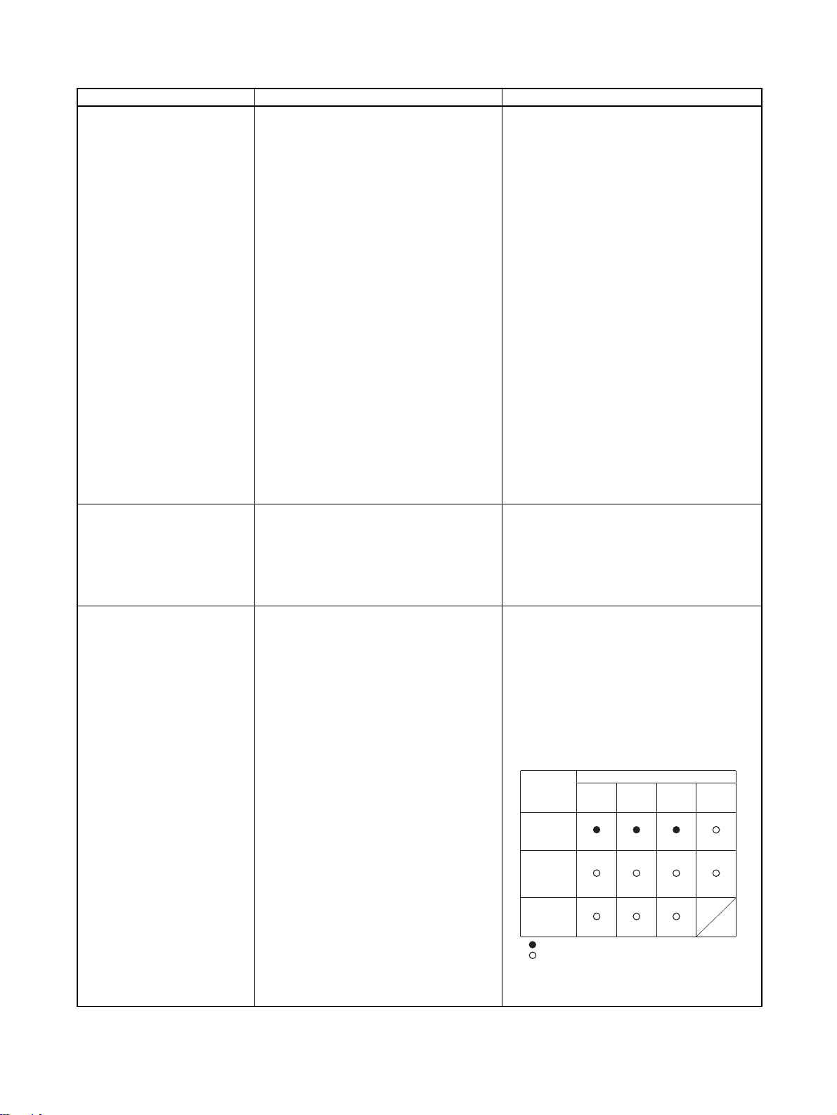
Addition of origin search operation modes
Three origin search operation pattern are
possible by combining the following set-
tings:
• Origin search operations: 3 settings
(Reversal modes 1 and 2, and Singledirection mode)
• Origin detection method: 1 setting
(With origin proximity input signal reversal)
Eleven origin search operation pattern are
possible by combining the following settings:
• Origin search operations: 4 settings
(Reversal modes 1, 2, and 3, and Singledirection mode)
• Origin detection methods: 3 settings (With
origin proximity input signal reversal, Without origin proximity input signal reversal,
Not use origin proximity input signal)
Origin
detection
method
With origin
proximity
input signal
reversal
Without
origin
proximity
input signal
reversal
Not use
origin
proximity
input signal
:
Combinations supported by unit version 1.3 or earlie
:
Combinations supported by unit version 2.0 or later
Note: Origin search operation patterns supported by
absolute encoders.
Origin search operation
Reversal
mode 1
(See note.)
(See note.)
(See note.)
(Refer to 8-2-4 Origin Search Operation.)
Reversal
mode 2
Single-
direction
mode
Reversal
mode 3
xvii

Functional upgrade Unit version 1.3 Unit version 2.0
Addition of origin search preset function
The preset function cannot be used during
origin searches.
The preset function can be used during origin searches.
For any of the origin search operations the
present position can be automatically set to
any specified value at the end of the origin
search. When using reversal mode 1 and an
absolute encoder, an offset can also be set
for the absolute origin.
(Refer to 8-2-6 Origin Search Preset and 8-6-
2 Absolute Encoder Operating Procedure.)
Note Changes in Axis Communications Status Flags
The conditions for setting and resetting the Axis Communications Status
Flags in word n+22 of the Common Operating Memory Area have been
changed accompanying the addition of the rejoin function. New conditions are
underlined in the following table.
Functional upgrade Unit version 1.3 or earlier Unit version 2.0 or later
Setting conditions • The flags will turn ON when connections
are made for the axes registered in the
scan list and MECHATROLINK communications start.
Resetting conditions • The flags will remain OFF when MECHA-
TROLINK communications cannot be
started when connections are made for
the axes registered in the scan list.
• The flags will turn OFF if MECHATROLINK communications stop because
the axis is disconnected.
• The flags will turn OFF if a Unit error
occurs that requires disconnection.
• The flags will turn ON when connections
are made for the axes registered in the
scan list and MECHATROLINK communications start.
• The flag will turn ON when the rejoin function is used to start MECHATROLINK communications for an axis registered in the
scan list.
• The flags will remain OFF when MECHATROLINK communications cannot be
started when connections are made for the
axes registered in the scan list.
• The flags will turn OFF if MECHATROLINK
communications stop because the axis is
disconnected.
• The flags will turn OFF if a Unit error occurs
that requires disconnection.
• The flags will turn OFF whenever a communications error occurs after MECHATROLINK communications have been
started for the axis.
With unit version 1.3 or earlier, once MECHATROLINK communications have been started by establishing connections, the Axis Communications Status Flags will not change unless communications
are disconnected (including Unit errors that required disconnection).
With unit version 2.0 or later, the Axis Communications Status Flags will turn OFF after connections
have been established whenever axis operation becomes impossible due to a communications error
(synchronous communications alarm or communications alarm).
Unit Version 2.0 to Unit Version 2.1
Functional upgrade Unit version 2.0 Unit version 2.1
Faster setting of transfer cycle
and communications cycle when
setting the absolute encoder PG
zero point position offset with an
origin search
A longer communications cycle must be
set using the settings given in a separate
table when the absolute encoder PG zero
point position offset is set with an origin
search.
The same communications cycle can be
set regardless of whether the absolute
encoder PG zero point position offset is
set with an origin search.
xviii

Read and Understand this Manual
Please read and understand this manual before using the product. Please consult your OMRON
representative if you have any questions or comments.
Warranty and Limitations of Liability
WARRANTY
OMRON's exclusive warranty is that the products are free from defects in materials and workmanship for a
period of one year (or other period if specified) from date of sale by OMRON.
OMRON MAKES NO WARRANTY OR REPRESENTATION, EXPRESS OR IMPLIED, REGARDING NONINFRINGEMENT, MERCHANTABILITY, OR FITNESS FOR PARTICULAR PURPOSE OF THE
PRODUCTS. ANY BUYER OR USER ACKNOWLEDGES THAT THE BUYER OR USER ALONE HAS
DETERMINED THAT THE PRODUCTS WILL SUITABLY MEET THE REQUIREMENTS OF THEIR
INTENDED USE. OMRON DISCLAIMS ALL OTHER WARRANTIES, EXPRESS OR IMPLIED.
LIMITATIONS OF LIABILITY
OMRON SHALL NOT BE RESPONSIBLE FOR SPECIAL, INDIRECT, OR CONSEQUENTIAL DAMAGES,
LOSS OF PROFITS OR COMMERCIAL LOSS IN ANY WAY CONNECTED WITH THE PRODUCTS,
WHETHER SUCH CLAIM IS BASED ON CONTRACT, WARRANTY, NEGLIGENCE, OR STRICT
LIABILITY.
In no event shall the responsibility of OMRON for any act exceed the individual price of the product on which
liability is asserted.
IN NO EVENT SHALL OMRON BE RESPONSIBLE FOR WARRANTY, REPAIR, OR OTHER CLAIMS
REGARDING THE PRODUCTS UNLESS OMRON'S ANALYSIS CONFIRMS THAT THE PRODUCTS
WERE PROPERLY HANDLED, STORED, INSTALLED, AND MAINTAINED AND NOT SUBJECT TO
CONTAMINATION, ABUSE, MISUSE, OR INAPPROPRIATE MODIFICATION OR REPAIR.
xix

Application Considerations
SUITABILITY FOR USE
OMRON shall not be responsible for conformity with any standards, codes, or regulations that apply to the
combination of products in the customer's application or use of the products.
At the customer's request, OMRON will provide applicable third party certification documents identifying
ratings and limitations of use that apply to the products. This information by itself is not sufficient for a
complete determination of the suitability of the products in combination with the end product, machine,
system, or other application or use.
The following are some examples of applications for which particular attention must be given. This is not
intended to be an exhaustive list of all possible uses of the products, nor is it intended to imply that the uses
listed may be suitable for the products:
• Outdoor use, uses involving potential chemical contamination or electrical interference, or conditions or
uses not described in this manual.
• Nuclear energy control systems, combustion systems, railroad systems, aviation systems, medical
equipment, amusement machines, vehicles, safety equipment, and installations subject to separate
industry or government regulations.
• Systems, machines, and equipment that could present a risk to life or property.
Please know and observe all prohibitions of use applicable to the products.
NEVER USE THE PRODUCTS FOR AN APPLICATION INVOLVING SERIOUS RISK TO LIFE OR
PROPERTY WITHOUT ENSURING THAT THE SYSTEM AS A WHOLE HAS BEEN DESIGNED TO
ADDRESS THE RISKS, AND THAT THE OMRON PRODUCTS ARE PROPERLY RATED AND INSTALLED
FOR THE INTENDED USE WITHIN THE OVERALL EQUIPMENT OR SYSTEM.
PROGRAMMABLE PRODUCTS
OMRON shall not be responsible for the user's programming of a programmable product, or any
consequence thereof.
xx

Disclaimers
CHANGE IN SPECIFICATIONS
Product specifications and accessories may be changed at any time based on improvements and other
reasons.
It is our practice to change model numbers when published ratings or features are changed, or when
significant construction changes are made. However, some specifications of the products may be changed
without any notice. When in doubt, special model numbers may be assigned to fix or establish key
specifications for your application on your request. Please consult with your OMRON representative at any
time to confirm actual specifications of purchased products.
DIMENSIONS AND WEIGHTS
Dimensions and weights are nominal and are not to be used for manufacturing purposes, even when
tolerances are shown.
PERFORMANCE DATA
Performance data given in this manual is provided as a guide for the user in determining suitability and does
not constitute a warranty. It may represent the result of OMRON's test conditions, and the users must
correlate it to actual application requirements. Actual performance is subject to the OMRON Warranty and
Limitations of Liability.
ERRORS AND OMISSIONS
The information in this manual has been carefully checked and is believed to be accurate; however, no
responsibility is assumed for clerical, typographical, or proofreading errors, or omissions.
xxi

xxii

PRECAUTIONS
This section provides general precautions for using the Position Control Unit and related devices.
The information contained in this section is important for the safe and reliable application of Position Control Units. You
must read this section and understand the information contained before attempting to set up or operate a Position Control
Unit.
1 Intended Audience . . . . . . . . . . . . . . . . . . . . . . . . . . . . . . . . . . . . . . . . . . . . . xxiv
2 General Precautions . . . . . . . . . . . . . . . . . . . . . . . . . . . . . . . . . . . . . . . . . . . . xxiv
3 Safety Precautions. . . . . . . . . . . . . . . . . . . . . . . . . . . . . . . . . . . . . . . . . . . . . . xxiv
4 Operating Environment Precautions . . . . . . . . . . . . . . . . . . . . . . . . . . . . . . . . xxv
5 Application Precautions . . . . . . . . . . . . . . . . . . . . . . . . . . . . . . . . . . . . . . . . . xxvi
6 Conformance to EC Directives . . . . . . . . . . . . . . . . . . . . . . . . . . . . . . . . . . . . xxviii
6-1 Applicable Directives . . . . . . . . . . . . . . . . . . . . . . . . . . . . . . . . . . . . xxviii
6-2 Concepts . . . . . . . . . . . . . . . . . . . . . . . . . . . . . . . . . . . . . . . . . . . . . . xxviii
6-3 Conformance to EC Directives . . . . . . . . . . . . . . . . . . . . . . . . . . . . . xxviii
6-4 Installation within Control Panels . . . . . . . . . . . . . . . . . . . . . . . . . . xxviii
xxiii

Intended Audience 1
1 Intended Audience
This manual is intended for the following personnel, who must also have
knowledge of electrical systems (an electrical engineer or the equivalent).
• Personnel in charge of installing FA systems.
• Personnel in charge of designing FA systems.
• Personnel in charge of managing FA systems and facilities.
2 General Precautions
The user must operate the product according to the performance specifications described in the operation manuals.
Before using the product under conditions which are not described in the
manual or applying the product to nuclear control systems, railroad systems,
aviation systems, vehicles, combustion systems, medical equipment, amusement machines, safety equipment, and other systems, machines, and equipment that may have a serious influence on lives and property if used
improperly, consult your OMRON representative.
Make sure that the ratings and performance characteristics of the product are
sufficient for the systems, machines, and equipment, and be sure to provide
the systems, machines, and equipment with double safety mechanisms.
This manual provides information for programming and operating the Unit. Be
sure to read this manual before attempting to use the Unit and keep this manual close at hand for reference during operation.
!WARNING It is extremely important that a Position Control Units and related devices be
used for the specified purpose and under the specified conditions, especially
in applications that can directly or indirectly affect human life. You must consult with your OMRON representative before applying Position Control Units
and related devices to the above-mentioned applications.
3 Safety Precautions
!WARNING Do not attempt to take any Unit apart while the power is being supplied. Doing
so may result in electric shock.
!WARNING Do not attempt to disassemble, repair, or modify any Units. Any attempt to do
so may result in malfunction, fire, or electric shock.
!WARNING Never touch any of the terminals while power is being supplied. Doing so may
result in serious electric shock.
!WARNING Provide safety measures in external circuits (i.e., not in the Programmable
Controller or Position Control Unit) to ensure safety in the system if an abnormality occurs due to malfunction of the PLC, malfunction of the PCU (Position
Control Unit), or external factors affecting the operation of the PLC or PCU.
Not providing sufficient safety measures may result in serious accidents.
xxiv

Operating Environment Precautions 4
• Emergency stop circuits, interlock circuits, limit circuits, and similar safety
measures must be provided in external control circuits.
• The PLC will turn OFF all outputs when its self-diagnosis function detects
any error or when a severe failure alarm (FALS) instruction is executed.
As a countermeasure for such errors, external safety measures must be
provided to ensure safety in the system.
• The PLC or PCU outputs may remain ON or OFF due to deposits on or
burning of the output relays, or destruction of the output transistors. As a
countermeasure for such problems, external safety measures must be
provided to ensure safety in the system.
• When the 24-V DC output (service power supply to the PLC) is overloaded or short-circuited, the voltage may drop and result in the outputs
being turned OFF. As a countermeasure for such problems, external
safety measures must be provided to ensure safety in the system.
• External safety measures must also be taken to ensure safety in the event
of unexpected operation when connecting or disconnecting the PCU’s
connectors.
!Caution Execute online editing only after confirming that no adverse effects will be
caused by extending the cycle time. Otherwise, the input signals may not be
readable.
!Caution Confirm safety at the destination node before transferring a program to
another node or changing contents of the I/O memory area. Doing either of
these without confirming safety may result in injury.
4 Operating Environment Precautions
!Caution Do not operate the control system in the following locations:
• Locations subject to direct sunlight.
• Locations subject to temperatures or humidity outside the range specified
in the specifications.
• Locations subject to condensation as the result of severe changes in temperature.
• Locations subject to corrosive or flammable gases.
• Locations subject to dust (especially iron dust) or salts.
• Locations subject to exposure to water, oil, or chemicals.
• Locations subject to shock or vibration.
!Caution Take appropriate and sufficient countermeasures when installing systems in
the following locations:
• Locations subject to static electricity or other forms of noise.
• Locations subject to strong electromagnetic fields.
• Locations subject to possible exposure to radioactivity.
• Locations close to power supplies.
xxv

Application Precautions 5
!Caution The operating environment of the PLC System can have a large effect on the
longevity and reliability of the system. Improper operating environments can
lead to malfunction, failure, and other unforeseeable problems with the PLC
System. Make sure that the operating environment is within the specified conditions at installation and remains within the specified conditions during the
life of the system.
5 Application Precautions
Observe the following precautions when using the PLC System.
!WARNING Always heed these precautions. Failure to abide by the following precautions
could lead to serious or possibly fatal injury.
• Always connect to a ground of 100
connecting to a ground of 100
• Always turn OFF the power supply to the PLC before attempting any of
the following. Not turning OFF the power supply may result in malfunction
or electric shock.
• Mounting or dismounting Power Supply Units, I/O Units, CPU Units, Inner Boards, or any other Units.
• Assembling the Units.
• Setting DIP switches or rotary switches.
• Connecting cables or wiring the system.
• Connecting or disconnecting the connectors.
!Caution Failure to abide by the following precautions could lead to faulty operation of
the PLC, the PCU, or the system, or could damage the PLC or PCU. Always
heed these precautions.
• Fail-safe measures must be taken by the customer to ensure safety in the
event of incorrect, missing, or abnormal signals caused by broken signal
lines, momentary power interruptions, or other causes. Not doing so may
cause malfunction resulting in serious injury.
• Interlock circuits, limit circuits, and similar safety measures in external circuits (i.e., not in the Programmable Controller) must be provided by the
customer.
• Install external breakers and take other safety measures against short-circuiting in external wiring. Insufficient safety measures against short-circuiting may result in burning.
• For CS-series PLCs, always tighten the mounting screw at the bottom of
the PCU to a torque of 0.4 N
• For CJ-series PLCs, lock the sliders securely until they click into place
when connecting the Power Supply Unit, CPU Unit, I/O Units, Special I/O
Units, or CPU Bus Units. Functions may not work correctly if the sliders
are not locked properly.
• Always attach the End Cover provided with the CPU Unit to the Unit on
the right end of the PLC. The CJ-series PLC will not operate properly if
the End Cover is not attached.
Ω or less when installing the Units. Not
Ω or less may result in electric shock.
⋅m.
xxvi

Application Precautions 5
• Take appropriate measures to ensure that the specified power with the
rated voltage and frequency is supplied in places where the power supply
is unstable. An incorrect power supply may result in malfunction.
• Remove the label after the completion of wiring to ensure proper heat dissipation. Leaving the label attached may result in malfunction.
• Disconnect the LG (line ground) terminal and GR (ground) terminal before
performing withstand voltage and insulation resistance tests.
• Confirm that set parameters and data operate properly.
• Perform wiring according to specified procedures.
• Double-check all wiring and switch settings before turning ON the power
supply. Incorrect wiring may result in burning.
• Check the user program for proper execution before actually running it on
the Unit. Not checking the program may result in unexpected operation.
• Confirm that no adverse effect will occur in the system before attempting
any of the following. Not doing so may result in an unexpected operation.
• Changing the operating mode of the PLC (including setting the Startup
Mode).
• Force-setting/force-resetting any bit in memory.
• Changing the present value of any word or any set value in memory.
• After replacing Units, resume operation only after transferring to the new
CPU Unit, Special I/O Units, CPU Bus Units, and externally connected
devices the contents of the DM Area, Holding Area, and other data
required for resuming operation. Not doing so may result in an unexpected operation.
• Do not pull on the cables or bend the cables beyond their natural limit.
Doing either of these may break the cables.
• Do not place objects on top of the cables or other wiring lines. Doing so
may break the cables.
• Before touching a Unit, be sure to first touch a grounded metallic object in
order to discharge any static build-up. Not doing so may result in malfunction or damage.
• Never turn OFF the power to the Unit while transferring data.
xxvii

Conformance to EC Directives 6
6 Conformance to EC Directives
6-1 Applicable Directives
•EMC Directives
6-2 Concepts
EMC Directives
OMRON devices that comply with EC Directives also conform to the related
EMC standards so that they can be more easily built into other devices or the
overall machine. The actual products have been checked for conformity to
EMC standards (see the following note). Whether the products conform to the
standards in the system used by the customer, however, must be checked by
the customer.
EMC-related performance of the OMRON devices that comply with EC Directives will vary depending on the configuration, wiring, and other conditions of
the equipment or control panel on which the OMRON devices are installed.
The customer must, therefore, perform the final check to confirm that devices
and the overall machine conform to EMC standards.
Note Applicable EMC (Electromagnetic Compatibility) standards are as follows:
EMS (Electromagnetic Susceptibility): EN61000-6-2
EMI (Electromagnetic Interference): EN61000-6-4
6-3 Conformance to EC Directives
The PCUs comply with EC Directives. To ensure that the machine or device in
which a PCU is used complies with EC Directives, the PCU must be installed
as follows:
1,2,3... 1. The PCU is defined as a in-panel device and must be installed within a
control panel.
2. Reinforced insulation or double insulation must be used for the DC power
supplies used for I/O.
3. PCUs complying with EC directives also meet the common emission standard (EN61000-6-4). The measures required to ensure that the standard
is met will vary with the overall configuration of the control panel, the other
devices connected to the control panel, wiring, and other conditions. The
customer must therefore confirm that EC directives are met for the overall
machine or device, particularly for the radiated emission requirement
(10 m).
6-4 Installation within Control Panels
Unnecessary clearance in cable inlet or outlet ports, operation panel mounting holes, or in the control panel door may cause electromagnetic wave leakage or interference. In this case, the product may fail to meet EC Directives. In
order to prevent such interference, fill clearances in the control panel with conductive packing. (In places where conductive packing comes in contact with
the control panel, ensure electrical conductivity by removing the paint coating
or masking these parts when painting.)
(Radiated emission: 10-m regulations)
xxviii

SECTION 1
Features and System Configuration
This section introduces the features of the Position Control Unit, explains the system configuration in which it is used, and
also provides information on basic operations, functions and specifications.
1-1 Features . . . . . . . . . . . . . . . . . . . . . . . . . . . . . . . . . . . . . . . . . . . . . . . . . . . . . . 2
1-2 System Configuration . . . . . . . . . . . . . . . . . . . . . . . . . . . . . . . . . . . . . . . . . . . 3
1-3 Basic Operations . . . . . . . . . . . . . . . . . . . . . . . . . . . . . . . . . . . . . . . . . . . . . . . 4
1-3-1 Position Control (Direct Operation) . . . . . . . . . . . . . . . . . . . . . . . . . 4
1-3-2 Speed Control and Torque Control . . . . . . . . . . . . . . . . . . . . . . . . . . 5
1-3-3 Other Operations. . . . . . . . . . . . . . . . . . . . . . . . . . . . . . . . . . . . . . . . 5
1-4 List of Functions and Specifications. . . . . . . . . . . . . . . . . . . . . . . . . . . . . . . . 6
1-4-1 General Specifications . . . . . . . . . . . . . . . . . . . . . . . . . . . . . . . . . . . 6
1-4-2 List of Functions and Specifications. . . . . . . . . . . . . . . . . . . . . . . . . 6
1-5 List of Functions by Purpose . . . . . . . . . . . . . . . . . . . . . . . . . . . . . . . . . . . . . 8
1-6 Comparison with Existing Models . . . . . . . . . . . . . . . . . . . . . . . . . . . . . . . . . 9
1
Fe at ur e s Section 1-1
9
8
5
4
3
2
1
0
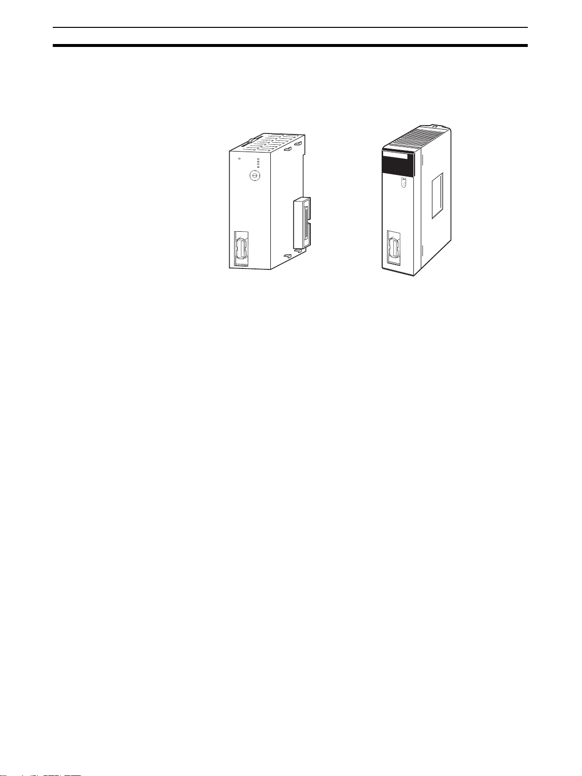
1-1 Features
Position Control Unit
CJ1W-NC271/471/F71 CS1W-NC271/471/F71
Compatible with the
MECHATROLINK-II Highspeed Field Network
High-speed, Highprecision Control Using
Data Communications
N
C
F71
M
L
K
R
U
N
E
R
C
E
R
H
E
R
M
D
C
E
B
U
N
F
IT
A
0
9
1
8
No.
2
7
3
6
4
5
M
LK
NCF71
RUN
ERC
UNIT
No.
ERH
ERM
MLK
CS
M
L
K
The Position Control Unit is a CS/CJ-series CPU Bus Unit. The Position Control Unit (PCU) receives commands from the CPU Unit's internal Auxiliary
Area and outputs positioning commands to MECHATROLINK-II Servo Drives.
MECHATROLINK is a registered trademark of MECHATROLINK Members
Association.
A MECHATROLINK-II high-speed (10 Mbps) communications interface is
used to control Servo Drives for up to 16 axes with a single CS/CJ-series Unit.
Shielded twisted-pair cables in daisy-chain formation make wiring simple and
enable multi-axis systems that require less wiring and are smaller in size.
Optimal motor performance can be achieved by transmitting data using communications between the Programmable Controller (PLC) and Servo Drives,
without having to set an upper limit for the designated speed. High-speed and
high-precision position control using high-resolution motors are possible.
Position Control (Direct
Operation)
Speed Control and Torque
Control
Compatible with
Servomotors with
Absolute Encoders
Transfer Data between
Host PLC and Servo Drive
2
Positioning can be performed simply by directly setting the target position and
target speed from the CPU Unit. Positioning to either absolute or relative positions is also possible. Interrupt feeding is also supported. With interrupt feeding, positioning is continued for a specified amount after an interrupt input
signal is received, and then the axis is stopped.
The Servo Drive's speed and torque can be controlled by directly specifying
the target speed and torque from the CPU Unit.
The PCU is compatible with Servomotors that have absolute encoders. Using
such Servomotors eliminates the need to repeatedly perform origin searches.
The Servo Drive's parameters and monitors can be set from the CPU Unit. All
the data for the multi-axis system can be centrally controlled from the host
PLC. This removes the difficulty in starting up devices or setting data when
replacing a Unit.
System Configuration Section 1-2
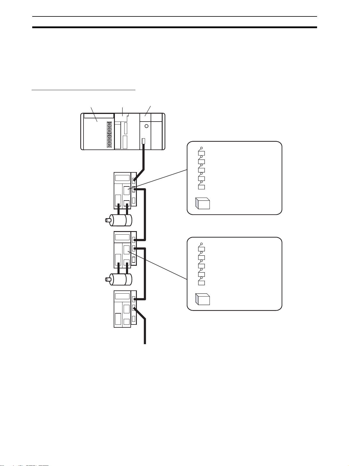
1-2 System Configuration
The PCU receives commands from the CPU Unit's ladder program and control signal status (forward/reverse rotation limit, origin, origin proximity, and
interrupt input signals) from devices connected externally to the Servo Drive,
and uses them to control Servo Drive positioning.
System Configuration Example
Power Supply Unit
Servo Drive
Servomotor
Servo Drive
Servomotor
Servo Drive
CJ-series
CPU Unit
CJ1W-NCF71
Position Control Unit
External inputs
Forward rotation limit input signal
Reverse rotation limit input signal
Origin input signal
Origin proximity input signal
Interrupt input signal
Etc.
24-V DC power supply
for interface
External inputs
Forward rotation limit input signal
Reverse rotation limit input signal
Origin input signal
Origin proximity input signal
Interrupt input signal
Etc.
24-V DC power supply
for interface
MECHATROLINK-II
(16 axes max.)
3
Loading...