

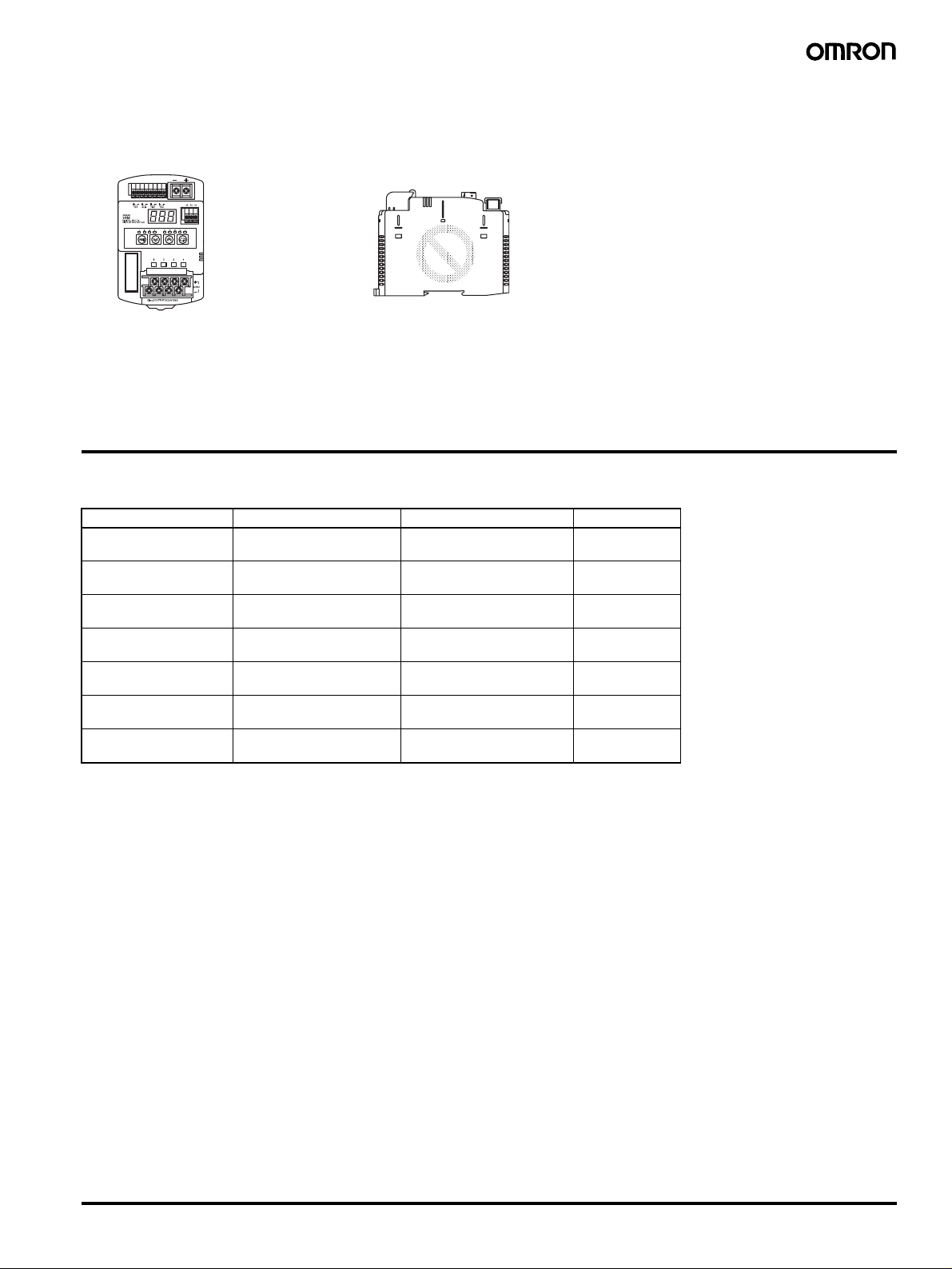
Omron S8M DATASHEET
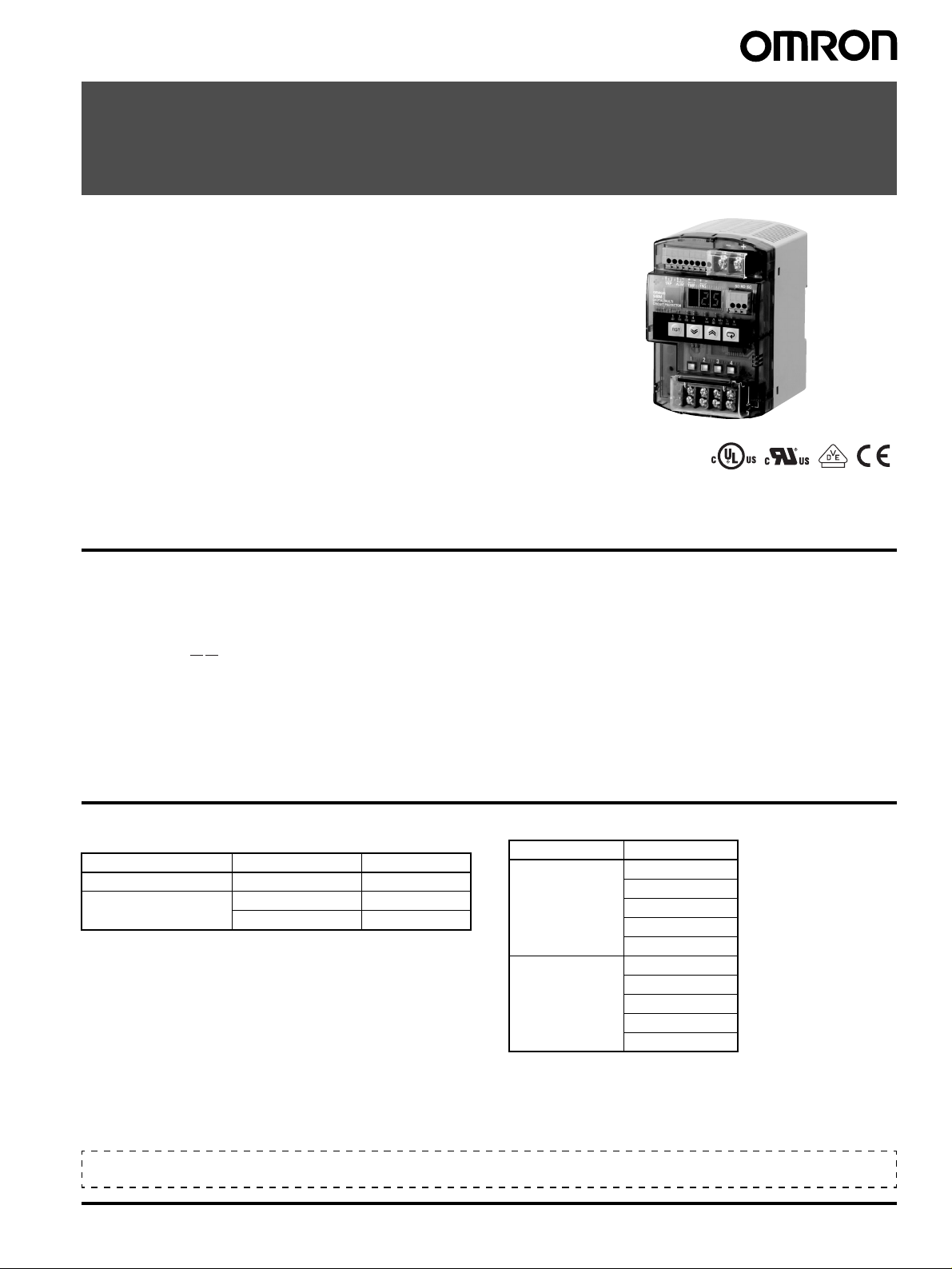
Digital Multicircuit Protector
S8M
Complete Flexible DC Circuit Protector That
Has a Wide Array of Displays, Alarm
Outputs, and Other Digital Functions.
• Four circuit protectors in one package
• Simple setting of curr ent tripping values for each bra nch outputs
in 0.1-A units
• Startup and shutdown sequence control
• Display and alarm functions (Input voltage, output current,
run time, and over-temperature)
• Outputs conform to UL Class 2 (at 24 VDC, S8M-CP04-RS
only)
• DIN Rail mounting
• Free Support Tool available
Note: Refer to Precautions for Safe Use on page 20.
Model Number Structure
■Model Number Lege nd
Note: Not all combinations are possible. Please refer to the list of models in Ordering Information below.
S8M-CP04- @@
12
1. Communications
None: Not supported
R: Supported (RS-232)
2. UL Class 2 Output (at 24 VDC)
None: Not compliant
S: Compliant
Ordering Information
Note: For details on normal stock models, contact your nearest
OMRON representative.
Communications UL Class 2 output Model number
None Not compliant S8M-CP04
Supported (RS-232C) Not compliant S8M-CP04-R
Compliant S8M-CP04-RS
Recommended Power Supplies
Series name Model number
S8VS S8VS-06024@@
S8VS-09024@@
S8VS-12024@@
S8VS-18024@@
S8VS-24024@@
S8VM S8VM-05024@@
S8VM-10024@@
S8VM-15024@@
S8VM-30024C
S8VM-60024C
Note: When selecting the power supply , be sure to include the
internal power consumption of the S8M (approx. 10 W) and not
just the power consumption of the load.
This Datasheet describes only the minimum setting operations required when using the S8M for the first time.
Refer to the S8M User's Manual (Cat. No. Z241), when making further settings.
Digital Multicircuit Protector S8M 1
Specifications
■Ratings/Characteristics
Item Model S8M-CP04 S8M-CP04-R S8M-CP04-RS
Number of branches 4
I/O
characteristics
Functions Tripping Abnormal voltage
Rated input voltage 24 VDC (19.2 to 26.4 VDC)
Allowable input current 17.0 A max. 16.0 A max.
Maximum tripping output current
(per branch output)
Internal voltage drop (See note 1.) 0.5 VDC max. (at 4.0 A) 0.7 VDC max. (at 3.8 A)
Output leakage current 10 mA max.
Power
consumption
(See note 2.)
Alarms Ove rvoltage Setting range: 20.0 to 28.8 V (in 0.1-V units), alarm output
Temperature Temperature Setting range: 25 to 80
Display Input voltage Display range: 17.0 to 30.0 V
External tripping input 19.2 to 30 VDC, minimum signal width: 10 ms, tripping within 20 ms of input
Startup sequence Can be enabled/disabled for each branch output, setting range: 0.0 to 99.9 s in 0.1-s units.
Shutdown sequence Can be enabled/disabled for each branch output, setting range: 0.0 to 99.9 s in 0.1-s units.
Communications None Supported (RS-232C)
Sampling pe r i od 1 ms
4 branches output,
normal operation
4 branches output,
tripping operati on
tripping
Abnormal current
tripping
Tripping alarm out-
put
Undervoltage Setting range: 18.0 to 26.4 V (in 0.1-V units), alarm output
Overcurrent Setting range: 0.5 to 4.0 A (in 0.1-A units), alarm output Setting range: 0.5 to 3.8 A (in 0.1-A
Run time Setting range: 0.0 to 99.9 kh (in 0.1-kh units), alarm output
Alarm output Transistor output
Over-temperature
output
Output current Branch output display range: 0.0 to 4.0 A
Run time Display range: 0.0 to 99.9 kh
Temperature Display range:
4.0 A 3.8 A
10 W max. (at 4.0 A) 15 W max. (at 3.8 A)
3 W max.
28.8 V (fixed), tripping alarm output
Setting range: 0.5 to 4.0 A (in 0.1-A units), tripping alarm
output
Transistor output
30 VDC max., 50 mA max., leakage current: 0.1 mA max., residual voltage: 2 V max.
(The alarm output is disabled if the time is set to 0.0 kh.)
30 VDC max., 50 mA max., leakage current: 0.1 mA max., residual voltage: 2 V max.
°C, over-temperature output
Transistor output
30 VDC max., 50 mA max., leakage current: 0.1 mA max., residual voltage: 2 V max.
Display accuracy: 2% rdg
Peak output current display range:0.0 to 10.0 A
Total current display range: 0.0 to 40.0 A
Display accuracy: 5% FS (4 A)
Display accuracy: 2% rdg
Display accuracy: 2
±1 digit max.
±1 digit max.
−10 to 100°C
°C ±1 digit max.
±1 digit max.
Setting range: 0.5 to 3.8 A (in 0.1-A
units), tripping alarm output
units), alarm output
2 Digital Multicircuit Protector S8M
Item Model S8M-CP04 S8M-CP04-R S8M-CP04-RS
Other Ambient operating temperature Refer to the derating curve in Engineering Data (with no condensation or icing) (See note 3.)
Storage temperature
−25 to 65°C
Ambient operating humidity 25% to 85% (storage humidity: 25% to 90%)
Dielectric strength 1.0 kVAC for 1 min (between all charged sections and all non-charged sections; detection cur-
rent: 20 mA)
500 VAC for 1 min (between all I/O and I/O signals/communications; detection current: 20 mA)
500 VAC for 1 min (between all I/O signals and communications; detection current: 20 mA)
500 VAC for 1 min (between input signals and all output signals; detection current: 20 mA)
Insulation resistance 100 M
Ω min. (between all charged sections and all non-charged sections) at 500 VDC
Ω min. (between all I/O and I/O signals/communications) at 500 VDC
100 M
100 M
Ω min. (between all I/O signals and communications) at 500 VDC
100 M
Ω min. (between input signals and all output signals) at 500 VDC
Vibration resistance 10 to 55 Hz, 0.375-mm single amplitude for 2 h each in X, Y, and Z directions
Shock resistance
EMI Conducted
2
150 m/s
, 3 times each in ±X, ±Y, and ±Z directions
Conforms to EN 61204-3 Class B
Emission
Radiated Emission Conforms to EN 61204-3 Class B
EMS Conforms to EN 61204-3 High severity levels
Approved standards UL: UL 508 (Listing), UL 60950-1
cUL: CSA C22.2 No. 107.1
cUR: CSA No. 60950-1
EN/VDE:EN 50178 (= VDE 0160), EN 60950-1
(= VDE 0805 Teil 1)
UL: UL 508 (Listing, Class 2:
Per UL 1310), UL60950-1
cUL: CSA C22.2 No. 107.1
cUR: CSA No. 60950-1
EN/VDE:EN 50178
(= VDE 0160),
EN 60950-1
(= VDE 0805 Teil 1)
Weight 400 g max.
Note: 1. A voltage drop will occur in the S8M. Consider the voltage drop at the output.
2. When selecting the power supply, be sure to include the internal power consumption of the S8M (approx. 10 W) and not just the power
consumption of the load.
3. Refer to Engineering Data on page 6 for details.
Digital Multicircuit Protector S8M 3

Connections
■Block Diagrams
S8M-CP04-R/-RS only
S8M-CP04-RS only
+V
DC input
power supply
Communications
terminals
RS-232C
Tripping alarm
output
Alarm output
Overtemperature
output
External
tripping input
SD
RD
SG
Power supply
circuit
Voltage
detection
Communications
circuit
Display
circuit
Processing
circuit
Switch
Temperature
detection
Cutoff
circuit
Cutoff
circuit
Cutoff
circuit
Cutoff
circuit
Current-detection
resistor
Current-detection
resistor
Current-detection
resistor
Current-detection
resistor
Thermal
fuse
Thermal
fuse
Thermal
fuse
Thermal
fuse
Current-detection
resistor
Current-detection
resistor
Current-detection
resistor
Current-detection
resistor
Cutoff
circuit
Current-
limiting
circuit
Cutoff
circuit
Current-
limiting
circuit
Cutoff
circuit
Current-
limiting
circuit
Cutoff
circuit
Current-
limiting
circuit
Fuse
+V
DC branch output 1
−V
Fuse
+V
DC branch output 2
−V
Fuse
+V
DC branch output 3
−V
Fuse
+V
DC branch output 4
−V
−V
4 Digital Multicircuit Protector S8M
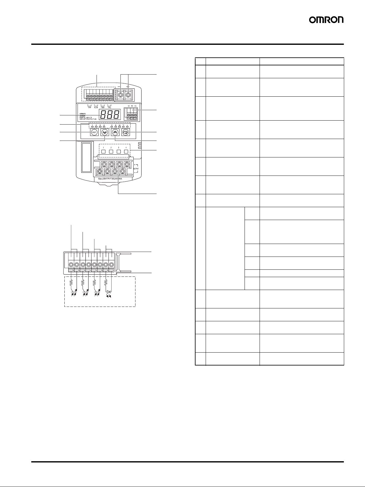
Construction and Nomenclature
■Nomenclature
4 5 6 7
8
9
13
12
Note: The S8M-CP04-RS is shown above.
4 Tripping alarm output (TRP)
5 Alarm output (ALM)
6 Over-temperature output (TMP)
Internal circuit configuration
7 External tripping input (TRG)
No. Name Function
1 Power Input Terminals
(+V), (
1
2 Branch Output
3 Status Indicators
14
4 Tripping Alarm Output
10
11
3
2
5 Alarm Output (+,
6 Over-temperature
7 External Tripping Input
8 Seven-segment Display
9 Unit Indicators
10 Mode Key Used to change the parameter being
11 Up Key Used to move to diff erent setting
12 Down Key Used to move to different setting
13 Reset Key (RST) Used when connecting branch
14 Communications
Note: 1. For detailed display methods, refer to Status Indicators on
−V)
Terminals (+V), (
(Red, Green)
(+,
−)
Output (+,
(+,
(Red)
(Orange)
Terminals (RD, SD, SG)
2. Configured from independent circuits, and either sinking or
3. Indicators 1 to 4 will not light except when the current is
4. Press for at least 3 s to enable operation.
5. Except for the S8M-CP04.
−)
−)
page 13.
sourcing applications are possible.
being displayed.
Connect to the input line.
Connect to the load lines.
−V)
Up to four branch outputs can be
connected.
Indicate the connection and cutoff
status for each branch output.
Cut off: Red, Connected: Green (See
note 1.)
Output (transistor: OFF) when the
error tripping operation functions.
(See note 2.)
−) Output (transistor: OFF) when a set
value for alarm detection is exceeded.
(See note 2.)
Output (transistor: OFF) when a set
value for over-temperature detection
is exceeded. (See note 2.)
The tripping operation can be
executed with an externally input
signal.
Displays measured values and set
values.
V Lit when the input voltage is being
displayed.
A Lit when the output current is being
displayed.
Flashes when the peak output current
is being displayed.
kh Lit when the run time is being
displayed.
°C Lit when the temperature is being
displayed.
s Lit when setting the sequence time.
1 to 4 Lit or flashing when displaying branch
output information. (See note 3.)
displayed or to reset the peak hold
current value.
modes or to increase a set value.
modes or to decrease a set value.
outputs for tripping operation. (See
note 4.)
Connect to the communications lines
(RS-232C). (See note 5.)
Digital Multicircuit Protector S8M 5

Engineering Data
(A)
(A)
y
y
(A)
■Derating Curve
120
S8M-CP04, S8M-CP04-R: Maximum output current 4.0 A
S8M-CP04-RS: Maximum output current 3.8 A
100
1
Derating Curve of the S8M
The ambient temperature that S8M can be
operating is limited by the maximum output
current of one branch terminal on ordinary
80
60
40
Maximum applied current for
any one branch output (%)
20
0
−100 10203040 6050 70−20
Ambient temperature (°C)
current condition.
Note: 1. Internal parts may occasionally be deteriorated or damaged. Do not use the S8M in areas outside the derating curve (i.e., in the area
shown by shading A in the above graph).
2. If there is a derating problem, use forced air cooling.
■Abnormal Current Tripping
Standard Detection
S8M-CP04/S8M-CP04-R S8M-CP04-RS
Time (ms)
Setting
range
Characteristics when steady
Time (ms)
Setting
range
Characteristics when steady
120.5
Current limited by
internal circuit
Current
100
20
3.8
0.5
100
Tripping region
20
4
6
Instantaneous Detection
S8M-CP04/S8M-CP04-R S8M-CP04-RS
Time (ms)
Characteristics when steady
Setting
range
Current limited b
internal circuit
Tripping region
20
4
120.5
Current (A)
Time (ms)
Setting
range
20
3.8 120.5
Tripping region
6
Characteristics when steady
Tripping region
12
Current limited by
internal circuit
Current
Current limited b
internal circuit
Current
6 Digital Multicircuit Protector S8M
■Mounting
Standar d Mounting
Correct
Note: 1. Improper mounting will interfere with heat dissipation and may occasionally result in deterioration or damage of internal parts.
Do not use any mounting method other than the standard one.
2. Take adequate measures to ensure proper heat dissipation to increase the long-term reliability of the S8M.
3. Install the S8M so that the air flow circulates around it, because the S8M is designed to radiate heat by means of natural air flow.
Face-up Mounting
Incorrect
Functions
■Functions
Alarm Alarm output Output status Alarm display
Abnormal voltage tripping TRP output: OFF
(normally ON )
Abnormal current tripping TRP output: OFF
(normally ON )
Overvoltage alarm ALM output: OFF
(normally ON )
Undervoltage alarm ALM output: OFF
(normally ON )
Overcurrent alarm ALM output: OFF
(normally ON )
Run time alarm ALM output: OFF
(normally ON )
Over-temperature output TMP output: OFF
(normally ON )
All branch outputs cut off. A10
Relevant branch output cut
off.
ON A20
ON A21
ON A22
ON A23
ON A30
A11
Digital Multicircuit Protector S8M 7
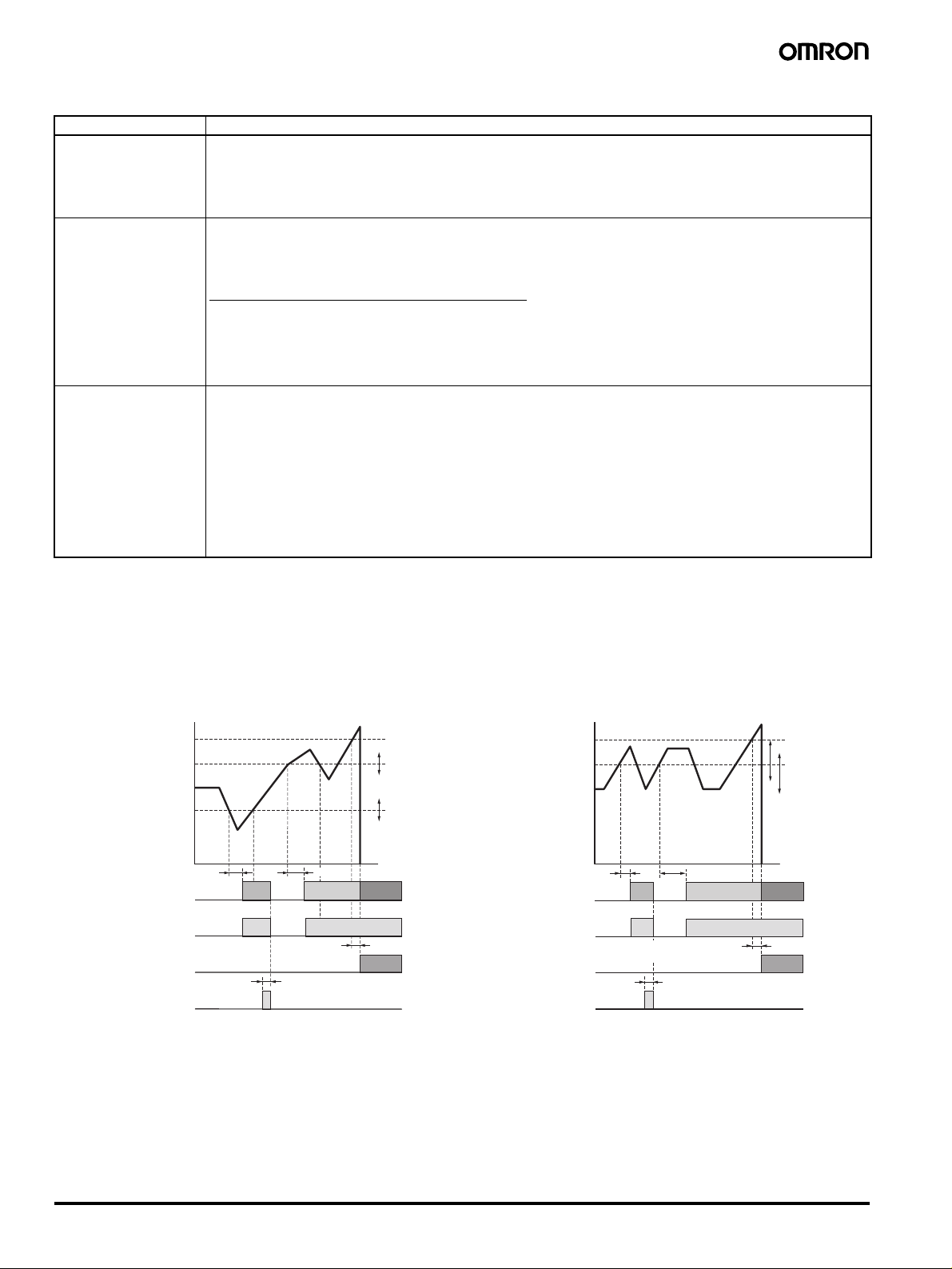
■Tripping Functions
y
Function Operation
Abnormal voltage tripping
Refer to Chart 1.
(See notes 2, 3 and 4.)
Abnormal current tripping
Refer to Chart 2.
(See notes 2 and 3.)
T ripping b y external signal
(See note 2.)
Note: 1. Two abnormal current tripping types are supported depending on the tripping current characteristics: Standard detection and
instantaneous detection. Select the required tripping type.
2. Outputs are cut off using semiconductor relays and electrical insulation is not provided.
3. The output will remain OFF and the alarm display and alarm output will not be cleared even if power is restored. The S8M must be reset
to restore operation. (Refer to List of Alarms on page 16 for details.)
4. The voltage at the power input terminals is monitored to detect abnormal voltages. To confirm correct output voltages, measure the
voltages at the branch output terminals.
The input voltage is monitored and all branch outputs are cut off if the detection voltage is reached. Notification of the
status is provided using the alarm display and the tripping alarm output (TRP).
The alarm display will alternate between the voltage and the alarm code (A10). The primary voltage is measured at
the input terminals.
Detection voltage: 28.8 V (fixed)
The output current is monitored and the branch output that is abnormal is cut off if the preset current is reached.
Notification of the status is provided using the alarm display and the tripping alarm output (TRP).
The alarm display will alternate between the current and the alarm code (A11).
Abnormal current detection setting range: 0.5 to 4.0 A (S8M-CP04-RS: 0.5 to 0.38 A) in 0.1-A units.
Either of two abnormal current tripping types can be set.
Standard detection: Tripping within 100 ms. (If a current exceeding the set v alue flo ws for 80 ms or more, it is detected
as an abnormal current and power is cut off within 20 ms.)
Instantaneous detection: Tripping within 20 ms. (If a current exceeding the set value flows for 10 ms or more, it is
detected as an abnormal current and power is cut off within 10 ms.)
(Refer to page 14 for the setting procedure.)
The output can be cut off by inputting a voltage to the external tripping input (TRG terminal). If a shutdown sequence
has been set, outputs will be cut off according to the shutdown sequence. (Refer to page 14 for information on the
shutdown sequence.)
External input signal width: 10 ms min.
External tripping enable/disable setting: Enabled
Input signal levels
High level: 19.2 to 30 VDC
Low level: 0 to 2.5 VDC
Tripping can also be performed by using communications (S8M-CP04-R/RS only).
Refer to the S8M User’s Manual (Cat. No. Z241) for information on tripping using communications.
Chart 1: Operation Timing Chart 2: Operation Timing
28.8 V (Abnormal voltage tripping)
25 V (Overvoltage alarm)
24 V (Rated)
18 V (Undervoltage alarm)
Alarm display
Alarm output
(See note.)
Tripping alarm output
(See note.)
Reset
Note: The alarm and tripping alarm output are both transistor outputs.
It is normall
0
100 ms 100 ms
A21 A20 A10
20 ms
3 s
ON and turns OFF when an alarm is detected.
(Fixed)
(Settable)
(Settable)
t
(Abnormal current tripping)
(Overcurrent alarm)
Tripping alarm output
(See note.)
4.0 A
3.5 A
3.0 A
(Normal current)
0
20 ms
(Instantaneous)
Alarm display
Alarm output
(See note.)
Reset
Note: The alarm and tripping alarm output are both transistor outputs.
It is normally ON and turns OFF when an alarm is detected.
100 ms
(Standard)
A22 A22 A11
Within 20 ms for instantaneous
detection and 100 ms for standard
detection (depends on tripping type).
3 s
(Settable)
(Settable)
t
8 Digital Multicircuit Protector S8M
 Loading...