

Page 1
New Product
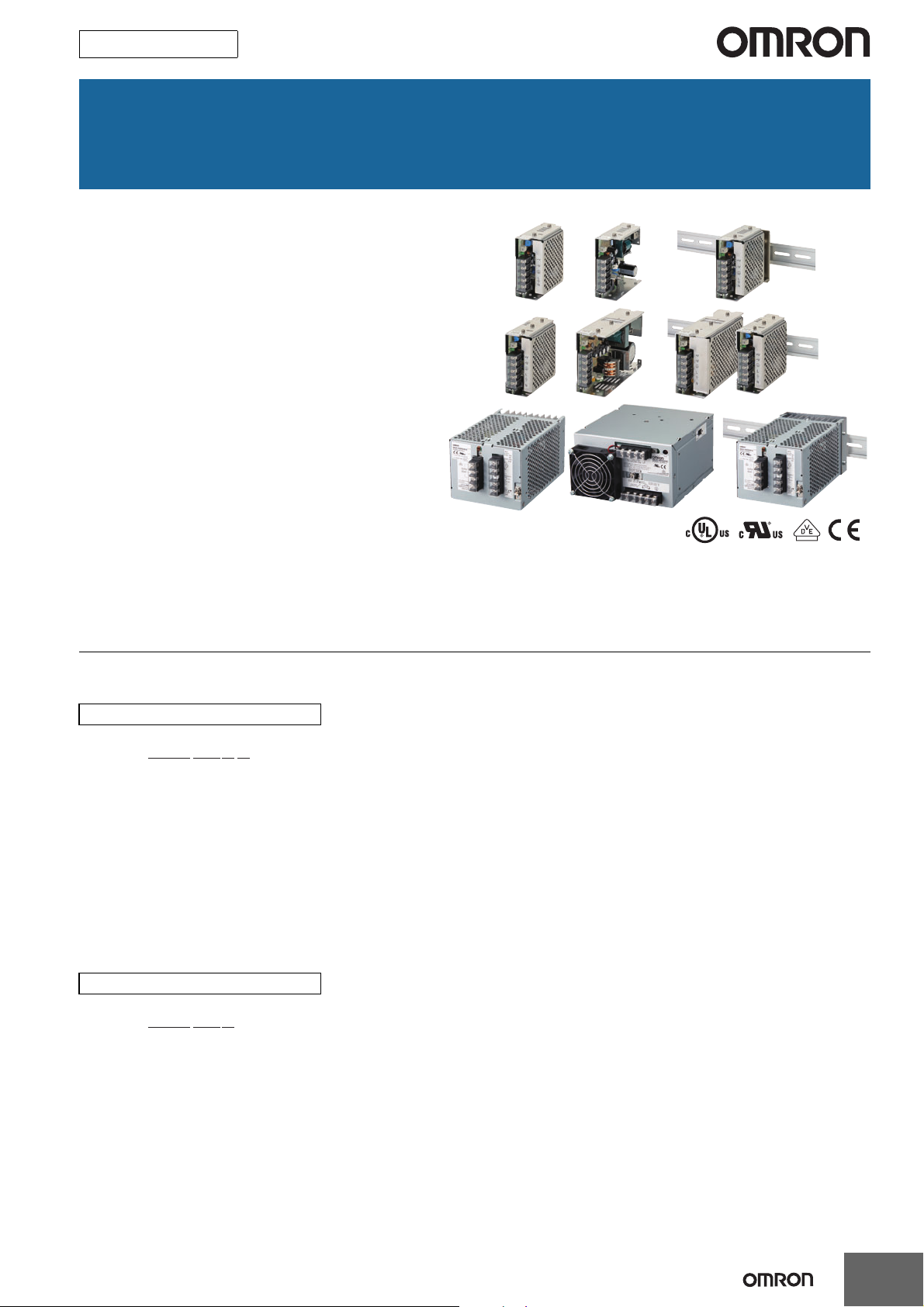
Switch Mode Power Supply
S8JX (15/35/50/100/150/300/600-W Models)
Low-profile Power Supply to Help
Reduce Panel Depth
• Easy Mounting:
Mounting Bracket provided as a standard feature.
(except for DIN Rail-mounting models)
Mounts to DIN Rail. (except 600-W model)
Screw-mount at the top. (except 300-/600-W models)
• Safety standards:
UL 508/60950-1
cUL CSA C22.2 No. 107.1
cUR CSA C22.2 No. 60950-1
EN 50178 (= VDE 0160)
EN 60950-1 (= VDE 0805 Teil 1)
• EMC: Conforms to EN 61204-3 Class A.
EMI: EN55011
()
EMS: EN61000-4
Note: Refer to Safety Precautions on page 17.
Model Number Structure
Model Number Legend
Note: Not all combinations are possible. Refer to List of Models in Ordering Information on page 2.
15-/35-/50-/100-/150-W Models
S8JX-G@@@@@@@
123
1. Power Ratings
015: 15 W
035: 35 W
050: 50 W
100: 100 W
150: 150 W
2. Output Voltage
05: 5 V
12: 12 V
15: 15 V
24: 24 V
300-/600-W Models
S8JX-G@@@@@@
1 2 3
1. Power Ratings
300: 300 W
600: 600 W
2. Output Voltage
24: 24 V
3. Configuration/mounting (covered type)
C: Front-mounting
CD: DIN Rail-mounting
4
3. Configuration (15/35/50/100/150 W model)
None: Open-frame
C: Covered
4. Configuration/mounting
None: Front-mounting
D: DIN Rail-mounting
1
Page 2
S8JX
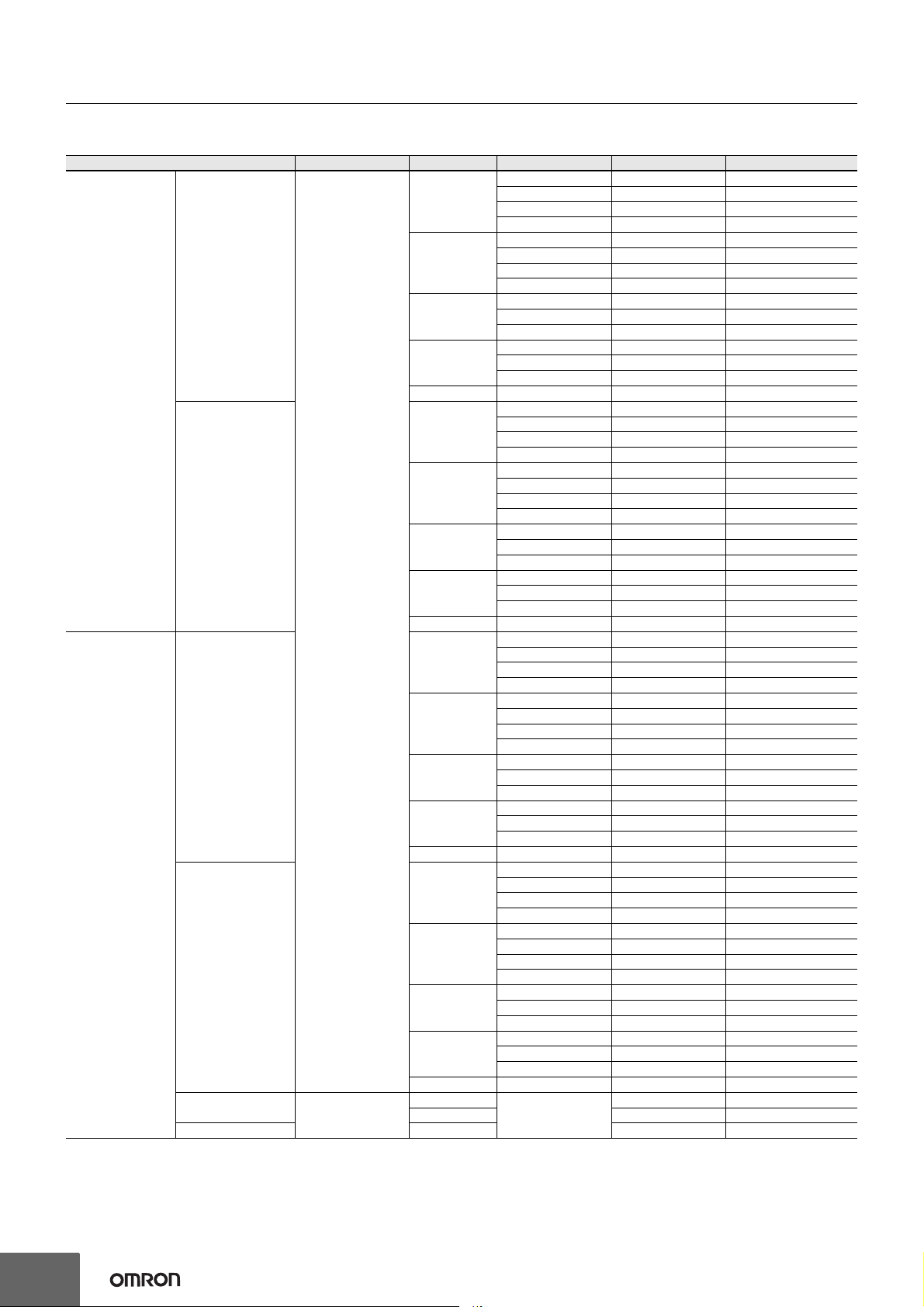
Ordering Information
List of Models
Note: For details on normal stock models, contact your nearest OMRON representative.
Configuration Input voltage Power ratings
15 W
35 W
Front-mounting *1
50 W
100 W
Open-frame Power
Supplies
Covered Power
Supplies
DIN Rail-mounting
100 to 240 VAC
(free)
(100 to 370 VDC *2)
Front-mounting *1
DIN Rail-mounting
Front-mounting *1
DIN Rail-mounting 300 W 14 A S8JX-G30024CD
100 to 120 VAC
200 to 240 VAC
(Swichable)
150 W 24 V 6.5 A S8JX-G15024
15 W
35 W
50 W
100 W
150 W 24 V 6.5 A S8JX-G15024D
15 W
35 W
50 W
100 W
150 W 24 V 6.5 A S8JX-G15024C
15 W
35 W
50 W
100 W
150 W 24 V 6.5 A S8JX-G15024CD
300 W
600 W 27 A S8JX-G60024C
*1. The front-mounting bracket is included as standard with the product.
*2. Safety standards, however, are not applicable.
Output voltage (VDC)
5 VDC 3 A S8JX-G01505
Output current Model
12 V 1.3 A S8JX-G01512
15 V 1 A S8JX-G01515
24 V 0.65 A S8JX-G01524
5 V 7 A S8JX-G03505
12 V 3 A S8JX-G03512
15 V 2.4 A S8JX-G03515
24 V 1.5 A S8JX-G03524
5 V 10 A S8JX-G05005
12 V 4.2 A S8JX-G05012
24 V 2.1 A S8JX-G05024
5 V 20 A S8JX-G10005
12 V 8.5 A S8JX-G10012
24 V 4.5 A S8JX-G10024
5 V 3 A S8JX-G01505D
12 V 1.3 A S8JX-G01512D
15 V 1 A S8JX-G01515D
24 V 0.65 A S8JX-G01524D
5 V 7 A S8JX-G03505D
12 V 3 A S8JX-G03512D
15 V 2.4 A S8JX-G03515D
24 V 1.5 A S8JX-G03524D
5 V 10 A S8JX-G05005D
12 V 4.2 A S8JX-G05012D
24 V 2.1 A S8JX-G05024D
5 V 20 A S8JX-G10005D
12 V 8.5 A S8JX-G10012D
24 V 4.5 A S8JX-G10024D
5 V 3 A S8JX-G01505C
12 V 1.3 A S8JX-G01512C
15 V 1 A S8JX-G01515C
24 V 0.65 A S8JX-G01524C
5 V 7 A S8JX-G03505C
12 V 3 A S8JX-G03512C
15 V 2.4 A S8JX-G03515C
24 V 1.5 A S8JX-G03524C
5 V 10 A S8JX-G05005C
12 V 4.2 A S8JX-G05012C
24 V 2.1 A S8JX-G05024C
5 V 20 A S8JX-G10005C
12 V 8.5 A S8JX-G10012C
24 V 4.5 A S8JX-G10024C
5 V 3 A S8JX-G01505CD
12 V 1.3 A S8JX-G01512CD
15 V 1 A S8JX-G01515CD
24 V 0.65 A S8JX-G01524CD
5 V 7 A S8JX-G03505CD
12 V 3 A S8JX-G03512CD
15 V 2.4 A S8JX-G03515CD
24 V 1.5 A S8JX-G03524CD
5 V 10 A S8JX-G05005CD
12 V 4.2 A S8JX-G05012CD
24 V 2.1 A S8JX-G05024CD
5 V 20 A S8JX-G10005CD
12 V 8.5 A S8JX-G10012CD
24 V 4.5 A S8JX-G10024CD
14 A S8JX-G30024C
24 V
2
Page 3

S8JX
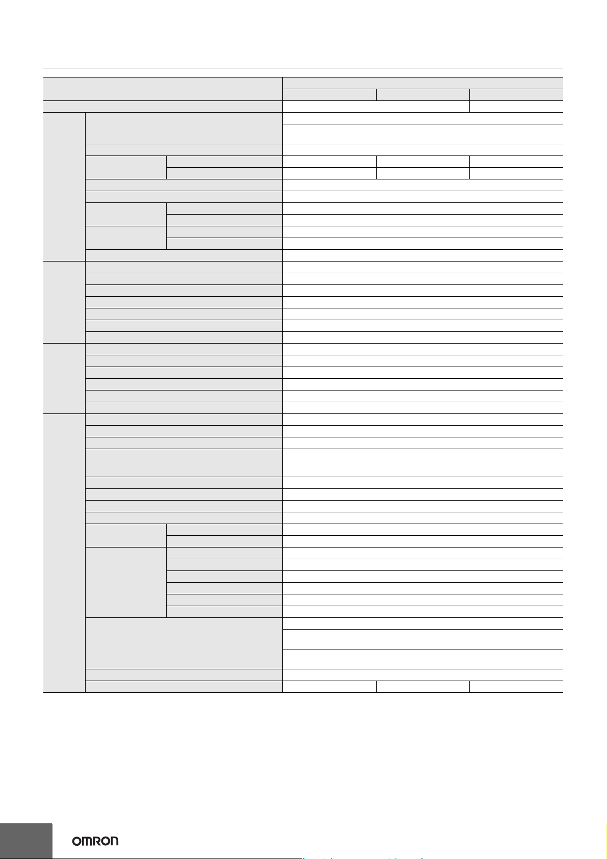
Ratings, Characteristics, and Functions
Input specification 100 to 240 V input
Item Power ratings *1 15 W 35 W
Efficiency 68% min. 73% min.
Voltage *2
Frequency *2 50/60 Hz (47 to 450 Hz)
100 V input 0.4 A 1 A
200 V input 0.25 A 0.6 A
100 V input 0.5 mA max.
200 V input 1 mA max.
100 V input 20 A max.
200 V input 40 A max.
Conducted Emissions *3 Conforms to EN 55011 Group 1 Class A and based on FCC Class A
Radiated Emissions Conforms to EN 55011 Group 1 Class A
Electrostatic Discharge Confirms to EN61000-4-2
Radiated Electromagnetic Field Confirms to EN61000-4-3
Electrical Fast Transient/Burst Confirms to EN61000-4-4
Surge Confirms to EN61000-4-5
Conducted Disturbance Confirms to EN61000-4-6
Voltage Dips/Short Interruptions Confirms to EN61000-4-11
Input
Output *4
Additional
functions
Other
Current *3
Power factor ---
Harmonic current emissions ---
Leakage current *3
Inrush current (for a
cold start at 25°C) *3
Noise filter Yes
Voltage adjustment range *5 −10% to 15% (with V. ADJ)
Ripple *3 2% (p-p) max.
Input variation influence 0.4% max.
Load variation influence 0.8% max. (0 to 100% load, rated input voltage)
Temperature variation influence 0.05%/°C max. (at rated input and output)
Startup time 500 ms max. (up to 90% of output voltage at rated input and output)
Hold time *3 20 ms min.
Overload protection *6 105% to 160% of rated load current, voltage drop, intermittent, automatic reset
Overvoltage protection *7 Yes
Overheat protection No
Parallel operation No
Series operation Yes (For up to two Power Supplies; external diodes required.)
Protective circuit operation indicator No
Ambient operating temperature
Storage temperature −25 to 65°C (with no icing or condensation)
Ambient operating humidity 25% to 85% (Storage humidity: 25% to 90%)
Dielectric strength
Insulation resistance 100 MΩ min. (between all outputs and all inputs/PE terminals) at 500 VDC
Vibration resistance 10 to 55 Hz, 0.375-mm single amplitude for 2h each in X, Y, and Z directions
Shock resistance 150m/s2, 3 times each in ±X, ±Y, ±Z directions
Output indicator Yes (Color: Green)
EMI
EMS
Approved standards
SEMI SEMI F47-0200 (200-VAC input)
Weight *8 250 g max.
*1. When a load is connected that has a built-in DC-DC converter, the overload protection may operate at startup and the Power Supply may not
start. Refer to Overload Protection on page 11.
*2. Do not use an Inverter output for the Power Supply. Inverters with an output frequency of 50/60 Hz are available, but the rise in the internal
temperature of the Power Supply may result in ignition or burning.
*3. Rated input voltage: 100 or 200 VAC at 100% load.
*4. Output characteristics: Specified at power supply output terminals.
*5. If the output voltage adjuster (V. ADJ) is turned, the voltage will increase by more than +15% of the voltage adjustment range. When adjusting
the output voltage, confirm the actual output voltage from the Power Supply and be sure that load is not damaged.
*6. For details, refer to Overload Protection on page 11.
*7. To reset the protection, turn OFF the input power for seven minutes or longer and then turn it back ON.
*8. The weight indicated is for Front-mounting, Open-frame Power Supplies.
100 to 240 VAC (85 to 264 VAC)
100 to 370 VDC
Note: This range is not applicable for the safety standards.
Refer to the derating curve in Engineering Data on page 9 (with no icing or
condensation)
3.0 kVAC for 1 min. (between all inputs and outputs; detection current: 20 mA)
2.0 kVAC for 1 min. (between all inputs and PE terminals; detection current: 20 mA)
1.0 kVAC for 1 min. (between all outputs and PE terminals; detection current: 20 mA)
UL 508 (Listing), UL 60950-1
cUL: CSA C22.2 No.107.1
cUR: CSA C22.2 No. 60950-1
EN/VDE: EN50178 (= VDE 0160), EN 60950-1 (= VDE 0805 Teil 1)
(Terminal block: Based on DIN50274 (VDE 0660-514))
3
Page 4
S8JX
Input specification 100 to 240 V input
Item Power ratings *1 50 W 100 W 150 W
Efficiency 76% min. 86% min.
Voltage *2
Frequency *2 50/60 Hz (47 to 450 Hz)
100 V input 1.4 A 2.5 A 3.5 A
200 V input 0.8 A 1.5 A 2.1 A
100 V input 0.5 mA max.
200 V input 1 mA max.
100 V input 20 A max.
200 V input 40 A max.
Conducted Emissions *3 Conforms to EN 55011 Group 1 Class A and based on FCC Class A
Radiated Emissions Conforms to EN 55011 Group 1 Class A
Electrostatic Discharge Confirms to EN61000-4-2
Radiated Electromagnetic Field Confirms to EN61000-4-3
Electrical Fast Transient/Burst Confirms to EN61000-4-4
Surge Confirms to EN61000-4-5
Conducted Disturbance Confirms to EN61000-4-6
Voltage Dips/Short Interruptions Confirms to EN61000-4-11
Input
Output *4
Additional
functions
Other
Current *3
Power factor ---
Harmonic current emissions ---
Leakage current *3
Inrush current (for a
cold start at 25°C) *3
Noise filter Yes
Voltage adjustment range *5 −10% to 15% (with V. ADJ)
Ripple *3 2% (p-p) max.
Input variation influence 0.4% max.
Load variation influence 0.8% max. (0 to 100% load, rated input voltage)
Temperature variation influence 0.05%/°C max. (at rated input and output)
Startup time 500 ms max. (up to 90% of output voltage at rated input and output)
Hold time *3 20 ms min.
Overload protection *6 105% to 160% of rated load current, voltage drop, intermittent, automatic reset
Overvoltage protection *7 Yes
Overheat protection No
Parallel operation No
Series operation Yes (For up to two Power Supplies; external diodes required.)
Protective circuit operation indicator No
Ambient operating temperature Refer to the derating curve in Engineering Data on page 9 (with no icing or condensation)
Storage temperature −25 to 65°C (with no icing or condensation)
Ambient operating humidity 25% to 85% (Storage humidity: 25% to 90%)
Dielectric strength
Insulation resistance 100 MΩ min. (between all outputs and all inputs/PE terminals) at 500 VDC
Vibration resistance 10 to 55 Hz, 0.375-mm single amplitude for 2h each in X, Y, and Z directions
Shock resistance 150m/s2, 3 times each in ±X, ±Y, ±Z directions
Output indicator Yes (Color: Green)
EMI
EMS
Approved standards
SEMI SEMI F47-0200 (200-VAC input)
Weight *8 300 g max. 550 g max. 600 g max.
*1. When a load is connected that has a built-in DC-DC converter, the overload protection may operate at startup and the Power Supply may not
start. Refer to Overload Protection on page 11.
*2. Do not use an Inverter output for the Power Supply. Inverters with an output frequency of 50/60 Hz are available, but the rise in the internal
temperature of the Power Supply may result in ignition or burning.
*3. Rated input voltage: 100 or 200 VAC at 100% load.
*4. Output characteristics: Specified at power supply output terminals.
*5. If the output voltage adjuster (V. ADJ) is turned, the voltage will increase by more than +15% of the voltage adjustment range. When adjusting
the output voltage, confirm the actual output voltage from the Power Supply and be sure that load is not damaged.
*6. For details, refer to Overload Protection on page 11.
*7. To reset the protection, turn OFF the input power for seven minutes or longer and then turn it back ON.
*8. The weight indicated is for Front-mounting, Open-frame Power Supplies.
100 to 240 VAC (85 to 264 VAC)
100 to 370 VDC
Note: This range is not applicable for the safety standards.
3.0 kVAC for 1 min. (between all inputs and outputs; detection current: 20 mA)
2.0 kVAC for 1 min. (between all inputs and PE terminals; detection current: 20 mA)
1.0 kVAC for 1 min. (between all outputs and PE terminals; detection current: 20 mA)
UL 508 (Listing), UL 60950-1
cUL: CSA C22.2 No.107.1
cUR: CSA C22.2 No. 60950-1
EN/VDE: EN50178 (= VDE 0160), EN 60950-1 (= VDE 0805 Teil 1)
(Terminal block: Based on DIN50274 (VDE 0660-514))
4
Page 5
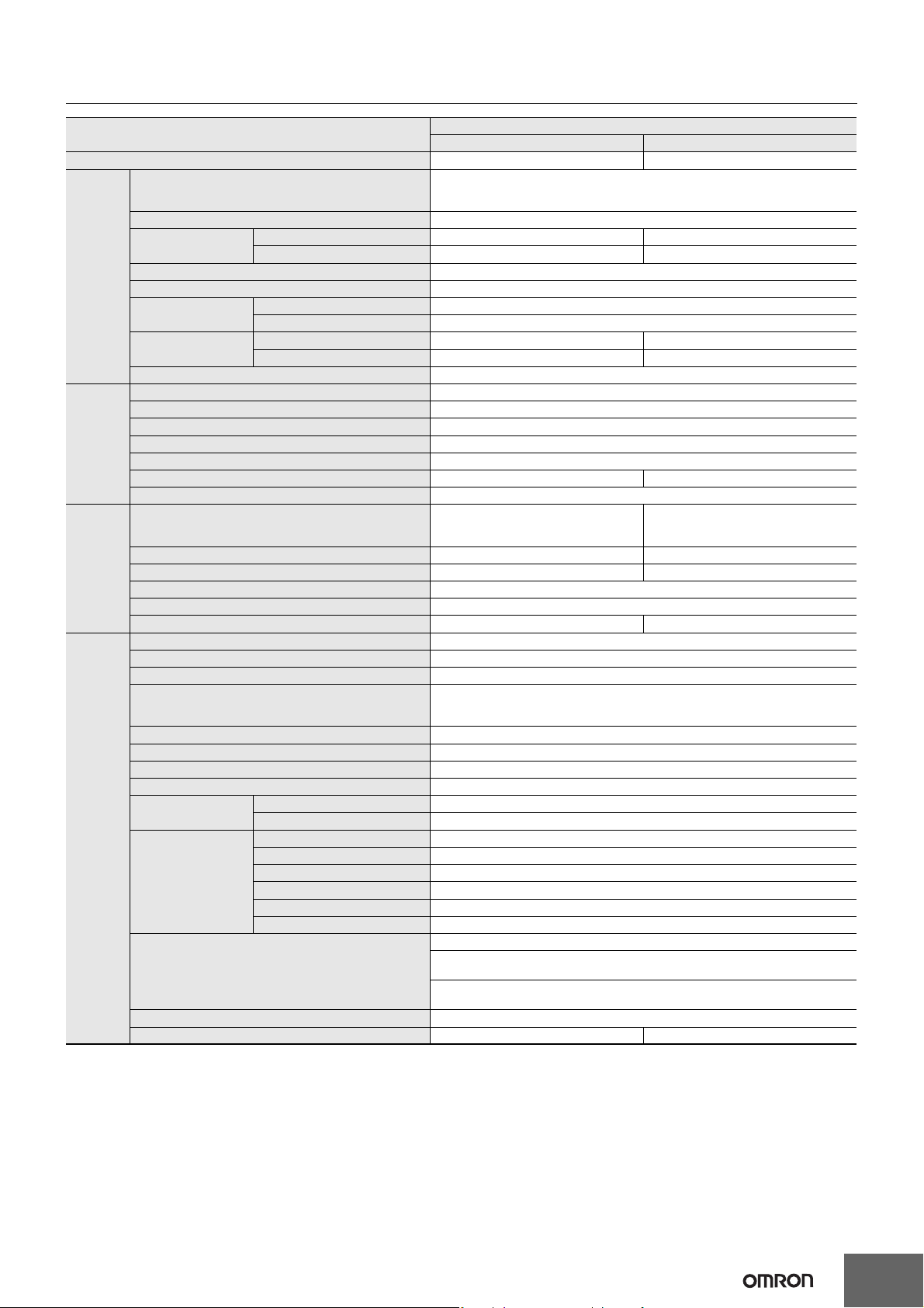
S8JX
Input specification 100/200 V (Selected)
Item Power ratings *1 300 W 600 W
Efficiency 82% min. 80% min.
Voltage *2
Frequency *2 50/60 Hz (47 to 450 Hz)
100 V input 8 A max. 14 A max.
200 V input 4.5 A max. 8 A max.
100 V input 0.5 mA max.
200 V input 1 mA max.
100 V input 25 A max. 30 A max.
200 V input 50 A max. 60 A max.
Conducted Emissions *3 Conforms to EN 55011 Group 1 Class A and based on FCC Class A
Radiated Emissions Conforms to EN 55011 Group 1 Class A
Electrostatic Discharge Confirms to EN61000-4-2
Radiated Electromagnetic Field Confirms to EN61000-4-3
Electrical Fast Transient/Burst Confirms to EN61000-4-4
Surge Confirms to EN61000-4-5
Conducted Disturbance Confirms to EN61000-4-6
Voltage Dips/Short Interruptions Confirms to EN61000-4-11
Input
Output *4
Additional
functions
Other
Current *3
Power factor ---
Harmonic current emissions ---
Leakage current *3
Inrush current (for a
cold start at 25°C) *3
Noise filter Yes
Voltage adjustment range *5 −10% to 15% (with V. ADJ)
Ripple *3 2% (p-p) max.
Input variation influence 0.4% max.
Load variation influence 0.8% max. (0 to 100% load, rated input voltage)
Temperature variation influence 0.05%/°C max.
Startup time 650 ms max. 500 ms max.
Hold time *3 20 ms min.
Overload protection *6
Overvoltage protection *7 Yes Yes *9
Overheat protection No Yes *9
Parallel operation Yes (up to 5 units)
Series operation Yes (For up to two Power Supplies; external diodes required.)
Protective circuit operation indicator No Yes (color: red)
Ambient operating temperature
Storage temperature −25 to 65°C (with no icing or condensation)
Ambient operating humidity 25% to 85% (Storage humidity: 25% to 90%)
Dielectric strength
Insulation resistance 100 MΩ min. (between all outputs and all inputs/PE terminals) at 500 VDC
Vibration resistance 10 to 55 Hz, 0.375-mm single amplitude for 2h each in X, Y, and Z directions
Shock resistance 150m/s2, 3 times each in ±X, ±Y, ±Z directions
Output indicator Yes (Color: Green)
EMI
EMS
Approved standards
SEMI SEMI F47-0200 (200-VAC input)
Weight *8 1,600 g max. 2,500 g max.
*1. When a load is connected that has a built-in DC-DC converter, the overload protection may operate at startup and the Power Supply may not
start. Refer to Overload Protection on page 11.
*2. Do not use an Inverter output for the Power Supply. Inverters with an output frequency of 50/60 Hz are available, but the rise in the internal
temperature of the Power Supply may result in ignition or burning.
*3. Rated input voltage: 100 or 200 VAC at 100% load.
*4. Output characteristics: Specified at power supply output terminals.
*5. If the output voltage adjuster (V. ADJ) is turned, the voltage will increase by more than +15% of the voltage adjustment range. When adjusting
the output voltage, confirm the actual output voltage from the Power Supply and be sure that load is not damaged.
*6. For details, refer to Overload Protection on page 11.
*7. To reset the protection, turn OFF the input power for three minutes or longer and then turn it back ON.
*8. The weight indicated is for Front-mounting, Open-frame Power Supplies.
*9. The protection-ON alarm indicator will light as soon as the output is interrupted. For resetting, turn OFF the input power, leave for more than
three minutes , and then turn it back ON again.
100 to 120 VAC (85 to 132 VAC)
200 to 240 VAC (170 to 264 VAC)
(Swichable)
105% of rated load current, voltage drop,
intermittent, automatic reset
Refer to the derating curve in Engineering Data on page 9 (with no icing or condensation)
3.0 kVAC for 1 min. (between all inputs and outputs; detection current: 25 mA)
2.0 kVAC for 1 min. (between all inputs and PE terminals; detection current: 25 mA)
1.0 kVAC for 1 min. (between all outputs and PE terminals; detection current: 25 mA)
UL 508 (Recognition), UL 60950-1
cUL: CSA C22.2 No.107.1
cUR: CSA C22.2 No. 60950-1
EN/VDE: EN50178 (= VDE 0160), EN 60950-1 (= VDE 0805 Teil 1)
(Terminal block: Based on DIN50274 (VDE 0660-514))
105% of rated load current, Inverted L
voltage drop, the circuit will be shut OFF
when the overload exceeds 5 s. *9
5
Page 6
S8JX
Connections
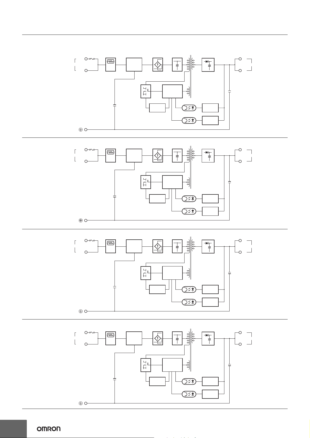
Block Diagrams
S8JX-G015@@@@ (15 W)
AC (L)
INPUT
AC (N)
Fuse
2.0 A
Inrush current
protection
Noise
filter
Rectifier Smoothing
circuit
Drive control
Circuit
Rectifier/
Smoothing circuit
+V
DC OUTPUT
−V
S8JX-G035@@@@ (35 W)
S8JX-G050@@@@ (50 W)
AC (L)
INPUT
AC (N)
AC (L)
INPUT
AC (N)
Fuse
3.15 A
Fuse
6.3 A
Inrush current
protection
Inrush current
protection
Noise
filter
Noise
filter
Overcurrent
detection
circuit
Photocoupler
Rectifier Smoothing
Overcurrent
detection
circuit
Rectifier Smoothing
circuit
Drive control
Circuit
circuit
Photocoupler
Voltage
detection
Overvoltage
detection circuit
Rectifier/
Smoothing circuit
Voltage
detection
Overvoltage
detection circuit
Rectifier/
Smoothing circuit
+V
DC OUTPUT
−V
+V
DC OUTPUT
−V
S8JX-G100@@@@ (100 W)
AC (L)
INPUT
AC (N)
Fuse
8 A
Inrush current
protection
Noise
filter
Overcurrent
detection
circuit
Rectifier
Overcurrent
detection
circuit
Drive control
Circuit
Smoothing
circuit
Drive control
Circuit
Photocoupler
Photocoupler
Voltage
detection
Overvoltage
detection circuit
Rectifier/
Smoothing circuit
Voltage
detection
Overvoltage
detection circuit
+V
DC OUTPUT
−V
6
Page 7
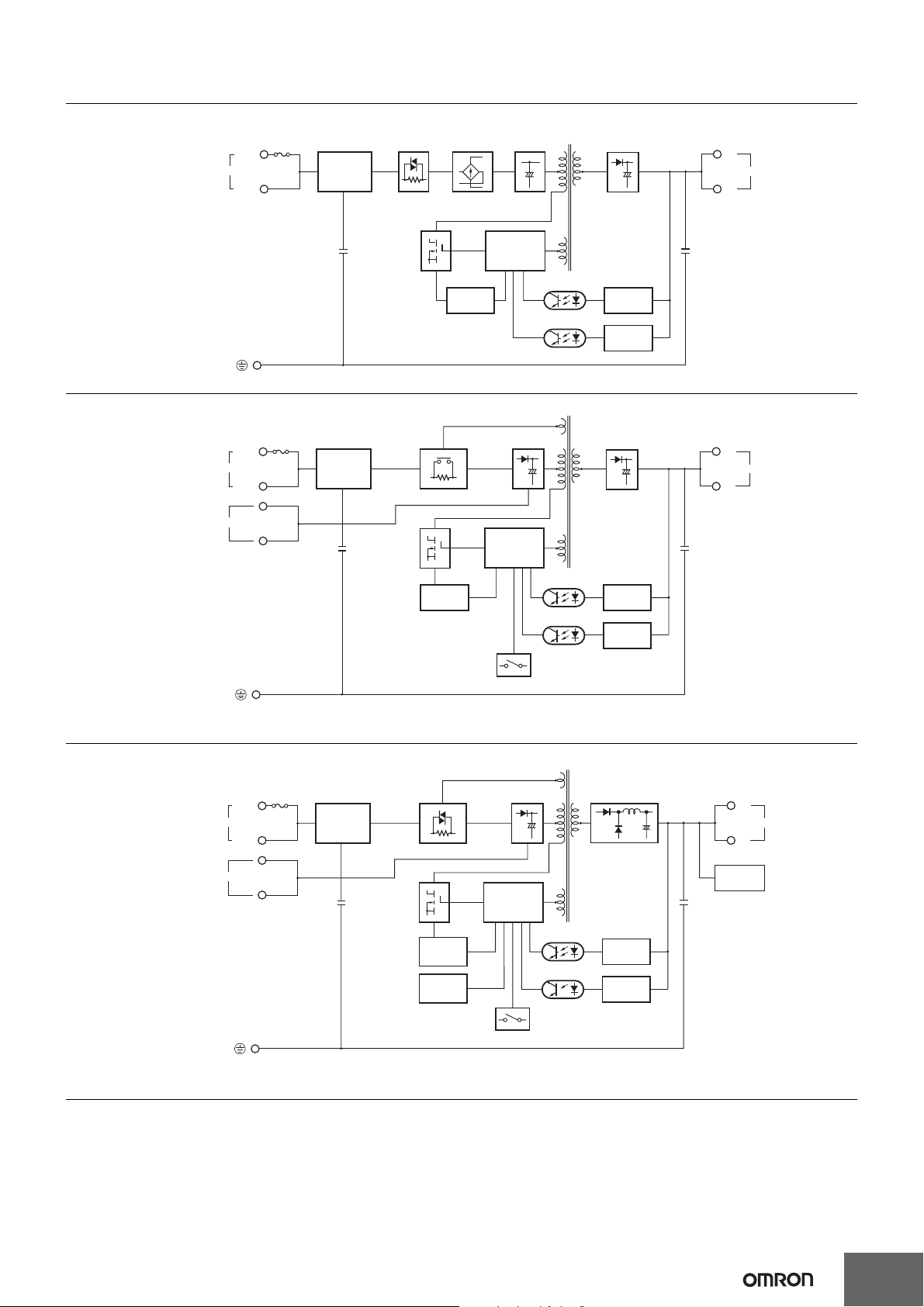
S8JX-G15024@@ (150 W)
INPUT
AC (L)
AC (N)
Fuse
10 A
Noise
filter
Inrush current
protection
Rectifier
Smoothing
circuit
Drive control
Circuit
Rectifier/
Smoothing circuit
S8JX
+V
DC OUTPUT
−V
S8JX-G30024@@ (300 W)
AC (L)
AC (N)
Fuse
10 A
INPUT
100/200V (Selectable)
Noise
filter
Overcurrent
detection
circuit
Inrush current protection
Overcurrent
detection
circuit
Parallel operation selector
Rectifier/
Smoothing circuit
Drive control
Circuit
Photocoupler
Photocoupler
Voltage
detection
Overvoltage
detection circuit
Rectifier/
Smoothing circuit
Voltage
detection
Overvoltage
detection circuit
Note: Short-circuit the input voltage selector terminals if the input is 100 to 120 VAC.
Keep the terminals open if the input is 200 to 240 VAC.
+V
DC OUTPUT
−V
S8JX-G60024@@ (600 W)
Rectifier/
AC (L)
AC (N)
Fuse
10 A
INPUT
100/200V (Selectable)
Noise
filter
Inrush current protection
Overcurrent
detection
circuit
Overheat
detection
circuit
Smoothing circuit
Drive control
Circuit
Photocoupler
Parallel operation selector
Rectifier/
Smoothing circuit
Voltage
detection
Overvoltage
detection circuit
Note: Short-circuit the input voltage selector terminals if the input is 100 to 120 VAC.
Keep the terminals open if the input is 200 to 240 VAC.
+V
DC OUTPUT
−V
Fan
7
Page 8
S8JX
H
D
C
B
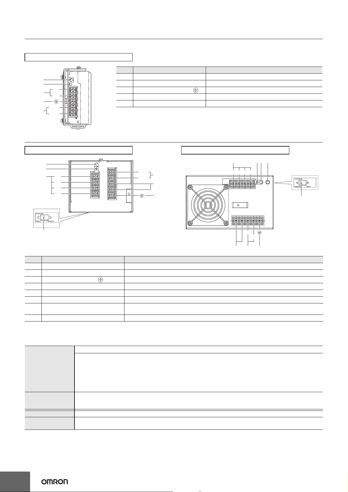
Construction and Nomenclature
Nomenclature
15-/35-/50-/100-/150-W Models
No. Name Function
D
E
+V
A
−V
C
AC (L)
B
AC (N)
Note: The S8JX-G05024CD is shown above.
1 DC Output Terminals (−V), (+V) Connect the load lines to these terminals.
2 AC Input Terminals (L), (N) Connect the input lines to these terminals. *1
3 Protective Earth Terminal (PE) ( ) Connect the ground line to these terminals. *2
4 Output Voltage Adjuster (V. ADJ) Use to adjust the voltage.
5 Output Indicator (DC ON: Green) Lights green while a direct current (DC) output is ON.
*1. The fuse is located on the (L) side. It is NOT user-replaceable.
*2. This is the protective earth terminal specified in the safety standards. Always ground this terminal.
300-W Model
E
F
+V
A
+V
−V
−V
Bottom
No. Name Function
1 DC Output Terminals (+V), (−V) Connect the load lines to these terminals.
2 AC Input Terminals (L), (N) Connect the input lines to these terminals. *1
3 Protective Earthing Terminal ( ) Connect the ground line to these terminals. *2
4 Input Voltage Selector Terminals Short-circuit the terminals if the input is 100 to 120 VAC and open the terminals if the input is 200 to 230 VAC.
5 Output Indicator (DC ON: Green) Lights while a Direct Current (DC) output is ON.
6 Output Voltage Adjuster (V. ADJ) It is possible to increase or decrease the output voltage.
Protection-ON Alarm Indicator
7
(DC ON: Red)
8 Selector of Parallel Operation Set the selector to PARALLEL if the Units are in parallel operation.
AC (L)
B
AC (N)
C
D
The red indicator will be lit if the overvoltage (for a 600-W model) or overheat protection (for a 600-W model)
circuit is triggered. This indicator will also be lit when overload (for a 600-W model) is detected.
600-W Model
A
−V−V
+V +V
AC (L)
GEF
Side
H
AC (N)
*1. The fuse is located on the (L) side. It is NOT user-replaceable.
*2. This is the protective earth terminal specified in the safety standards. Always ground this terminal.
Reference Values
Reliability (MTBF)
Definition
Life expectancy 10 yrs. min.
Definition
8
Value
15 W: 300,000 hrs
35 W: 300,000 hrs
50 W: 300,000 hrs
100 W: 270,000 hrs
150 W: 250,000 hrs
300 W: 400,000 hrs
600 W: 300,000 hrs
MTBF stands for Mean Time Between Failures, which is calculated according to the probability of accidental device
failures, and indicates reliability of devices.
Therefore, it does not necessarily represent a life of the product.
The life expectancy indicates average operating hours under the ambient temperature of 40°C and a load rate of 50%.
Normally this is determined by the life expectancy of the built-in aluminum electrolytic capacitor.
Page 9

Engineering Data
Derating Curves (Standard Mounting)
15-/35-/50-/100-/150-W Models
Open-frame Power Supplies Covered Power Supplies
120
120
S8JX
100
Load rate (%)
80
60
40
20
0
−20 −10 0 10 20 30 40 50 60 70 80
Ambient Temperature (°C) Ambient Temperature (°C)
A
100
Load rate (%)
80
60
40
20
0
−20 −10 0 10 20 30 40 50 60 70 80
A
Note: 1. Internal parts may occasionally deteriorate or be damaged. Do not use the Power Supply in areas outside the derating curve (i.e., the
area shown by shading A in the above graph).
2. If there is a derating problem, use forced air-cooling.
300-/600-W Models
Single Unit Operation Parallel Operation
120
100
Load rate (%)
80
60
40
20
0
−20 −10 0 10 20 30 40 50 60 70 80
Ambient Temperature (°C) Ambient Temperature (°C)
A
Note: 1. Internal parts may occasionally deteriorate or be damaged. Do not use the Power Supply in areas outside the derating curve (i.e., the
area shown by shading A in the above graph).
2. If there is a derating problem, use forced air-cooling.
120
100
Load rate (%)
80
60
40
20
0
−20 −10 0 10 20 30 40 50 60 70 80
A
Solid line
Dotted line
Front-mounting,
Bottom-mounting,
DIN Rail mounting,
Side mounting (600W)
Side mounting (300W)
9
Page 10

S8JX
Mounting
15-/35-/50-/100-/150-W Models
The following three mounting methods are possible.
A. Front-mounting: Refer to Mounting Bracket Provided with Front-mounting Power Supplies
B. Bottom-mounting
C. Side-mounting
Note: Additional mounting methods are also available using DIN Rail-mounting models.
Standard Mounting
15-/35-/50-/100-/150-W Models
a
on page 14.
B
C
Front-mounting
*
DIN Rail-mounting
Bottom-mo
unting
Vertical Side-mounting
*
*
Horizontal Side-mounting
*
Note: 1. Improper mounting will interfere with heat dissipation and may occasionally result in deterioration or damage of internal parts. Use the
standard mounting method only.
2. When mounting the Power Supply, mounting it to a metal plate (*) is recommended.
3. Install the Power Supply so that the air flow circulates around the Power Supply, as the Power Supply is designed to radiate heat by
means of natural air flow.
300-W Model
Front-mounting
DIN Rail mounting
Bottom-mounting
20mm min. 20mm min. 20mm min.20mm min.
Note: 1. Improper mounting will interfere with heat dissipation and may occasionally result in deterioration or
damage of internal parts. Use the standard mounting method only.
2. When mounting the Power Supply, mounting it to a metal plate (*) is recommended.
3. Install the Power Supply so that the air flow circulates around the Power Supply, as the Power Supply
is designed to radiate heat by means of natural air flow.
Side-mo
unting
10
Front-mounting
600-W Model
Side-mounting
Bottom-mounting
20mm min.20mm min.
20mm min.
20mm min.
Note: 1. Improper mounting will interfere with heat dissipation and may occasionally
result in deterioration or damage of internal parts. Use the standard mounting
method only.
2. When mounting the Power Supply, mounting it to a metal plate (*) is
recommended.
3. Install the Power Supply so that the air flow circulates around the Power
Supply, as the Power Supply is designed to radiate heat by means of natural
air flow.
Page 11

S8JX
Overload Protection
The Power Supply is provided with an overload protection function
that protects the power supply from possible damage by overcurrent.
When the output current rises above 105% min. of the rated current,
the protection function is triggered, decreasing the output voltage.
When the output current falls within the rated range, the overload
protection function is automatically cleared.
(Reference value)
15-/35-/50-/100-/150-W Models
Output voltage (V)
Intermittent operation
0
50
Load rate (%)
300-W Model
100
Overvoltage Protection
15-/35-/50-/100-/150-W Models
Consider the possibility of an overvoltage and design the system so
that the load will not be subjected to an excessive voltage even if the
feedback circuit in the power supply fails. When an excessive voltage
that is approximately 130% of the rated voltage or more is output, the
output voltage is shut OFF, preventing damage to the load due to
overvoltage. Reset the input power by turning it OFF for at least seven
minutes and then turning it back ON again.
300-/600-W Models
Consider the possibility of an overvoltage and design the system so
that the load will not be subjected to an excessive voltage even if the
feedback circuit in the Power Supply fails. When an excessive voltage
that is approximately 130% of the rated voltage or more is output, the
output voltage is shut OFF, preventing damage to the load due to
overvoltage. Reset the input power by turning it OFF for at least seven
minute and then turning it back ON again.
(Reference value)
Overvoltage protection
Output voltage (V)
Rated output
Voltage
Variable range
Operating
Output voltage (V)
Intermittent operation
0
50
100
Load rate (%)
600-W Model
Output voltage (V)
Output interrupted
0
If an excessive current flows for 5 s or more, the output will be turned
OFF and simultaneously the protection-ON alarm indicator will be lit.
To reset the S8JX, turn OFF the power, leave the S8JX for at least
three minutes, and then turn it ON again.
Note: 1. When a load is connected that has a built-in DC-DC
50
100
Load rate (%)
converter, the overload protection may operate at startup
and the power supply may not start.
2. Internal parts may occasionally deteriorate or be damaged
if a short-circuited or overcurrent state continues during
operation.
3. Internal parts may possibly deteriorate or be damaged if the
Power Supply is used for applications with frequent inrush
current or overloading at the load end. Do not use the Power
Supply for such applications.
0 V
Note: Do not turn ON the power again until the cause of the
overvoltage has been removed.
Overheat Protection
600-W Model
If the internal temperature rises excessively as a result of fan failure
or any other reason, the overheat protection circuit will be triggered to
protect the internal parts and simultaneously the protection-ON alarm
indicator will be lit. Reset the input power by turning it OFF for at least
three minutes and then turning it back ON again.
Inrush Current, Startup Time, Output Hold Time
Input ON
AC input
voltage
Inrush current on input application
AC input
current
90%
Output
voltage
Startup time Hold time (20 ms min.)
Note: A maximum startup time of 500 ms is required. Construct a
system configuration that considers the startup time of other
devices.
Input OFF
96.5%
11
Page 12

S8JX
Dimensions (Unit: mm)
Front-mounting Models
S8JX-G015@@ (15 W)
S8JX-G015@@C (15 W)
S8JX-G035@@ (35 W)
S8JX-G035@@C (35 W)
S8JX-G050@@ (50 W)
S8JX-G050@@C (50 W)
Label
9.5
Five, M3.5
Cover
Label
8.2
9.5
Five, M3.5
Cover
8.2
±1
35.5
39.5
Two, M3 (Depth 4 mm max.)
±1
36
±1
40
17.5
5 max.
3.5
3.5
±1
91
±0.5
75
7.5
26.5
5 max.
3.5
±0.5
75
±1
92
8
3.5
3.5 dia.
3.5 dia.
±1
90
±0.5
82
±0.5
78
±0.5
50
±1
100
±0.5
92
±0.5
92
10 max.
±1
4.5
8.5
3.5 dia.
15
10 max.
4.5
4.5
3.5 dia.
Panel mounting holes dimensions
Surface screw mounting
Two, M3
Side
Mounting
±0.5
82
Two, M3
Bottom
Mounting
±0.5
78
Panel mounting holes dimensions
Surface screw mounting
Two, M3
Side
Mounting
±0.5
92
Bottom
Mounting
Two, M3
±0.5
92
±0.5
75
±0.5
75
S8JX-G100@@ (100 W)
S8JX-G100@@C (100 W)
S8JX-G15024 (150 W)
S8JX-G15024C (150 W)
Five, M3.5
Two, M3
(Depth 4 mm max.)
±0.5
20
10 max.
Label
8.2
9.5
Cover
±1
48
±1
50
Two, M3
(Depth 4 mm max.)
3.5 dia.
100 W
3.5 dia.
5
5
16
65
150
150 W
±0.5
141
±0.5
141
122
±1
±0.5
26.5
20
100·150 W
3.5
5 max.
75
3.5
28
Panel mounting holes dimensions
Surface screw mounting
Side
±0.5
Mounting
±1
92
8
Bottom
Mounting
Two, M3
141
141
Two, M3
±0.5
±0.5
±0.5
75
12
Page 13

S8JX
S8JX-G30024C (300 W)
4 max.
±1
92
±1
110
S8JX-G60024C (600 W)
Nine, M4 terminal screws
Eight, M4 holes
20 max.
(depth: 8 max. on both sides)
167.1
±1
Panel mounting holes dimensions
Surface screw mounting
10
8.6
19
19
136
136
±0.5
±0.5
±0.5
50
21
±0.5
90
10
Side
Mounting
Bottom
Mounting
Four, M4 holes
(depth: 8 max.)
Four, 4.5 dia.
±0.5
136
Four, 4.5 dia.
±0.5
136
±0.5
50
±0.5
90
±1
150
Nine, M4 terminal screws
8.6 10
Panel mounting holes dimensions
Surface screw mounting
Four, 4.5 dia.
Side
Mounting
±0.5
124
Four, 4.5 dia.
Bottom
Mounting
±0.5
137
Eight, M4 holes
±0.5
24.4
±1
92
(depth: 8 max. on both sides)
±1
159.8
±0.5
50
20.9
±0.5
137
124
±0.5
14.8
11
Four, M4 holes
(depth: 8 max.)
±0.5
100
42
108.6
±0.5
50
±0.5
100
13
Page 14

S8JX
Mounting Bracket Provided with Front-mounting Power Supplies a
15-/35-/50-/100-/150-W Models
Front-mounting Bracket
Dimensions
1.5
t = 1.0
11
9
60
5
31.5
4.6 15
Two, 3.5 dia.
20
15
20.5
±0.2
74
4.6
11
4.7
Material: Stainless steel
300-/600-W Models
Front-mounting Bracket
7.5 7.5
145
±0.5
160
92
Mounting
dimensions
Two, M3
60
20
Four, 5dia.
Front-mounting Method
Temporarily attach the enclosed mounting
bracket as shown in the illustration on the right,
hook the holes (parts a) in the Power Supply on
hooks on the mounting bracket (parts b), and
secure the Power Supply with two mounting
screws.
Dimensions with
10 dia.
R2.5
15
t = 1.6
30
Mounting Brackets
300-W Model
145
Note: Mounting screws are
not provided.
a
Power Supply
a
Attaching the Mounting Brackets
300-W Model
±0.5
b
Mounting bracket
b
±0.2
36.4
32
Note: Mounting Brackets are provided in a set, one
for the right side and one for the left side.
48
±0.5
80
Four, M 4
600-W Model 600-W Model
±0.5
145
±0.5
120
Four, M 4
Note: To provide ventilation space, the body
will shift forward by 21.6 mm from the
mounting surface.
Note: To provide ventilation space, the body
will shift forward by 23.6 mm from the
mounting surface.
14
Page 15

DIN Rail-mounting Models
S8JX-G015@@ (15 W)
S8JX-G015@@CD (15 W)
S8JX-G035@@ (35 W)
S8JX-G035@@CD (35 W)
6 max.
Label
9.5
S8JX
±1
44
8.2
10 max.
±1
90
14.5 max.
5 max.
±1
91
S8JX-G050@@D (50 W)
S8JX-G050@@CD (50 W)
Five, M3.5
Cover
6 max.
Label
9.5
Five, M3.5
Cover
47
98.6
±1
44
8.2
±1
36
±1
40
10 max.
100
±1
108.6
7 (Sliding: 16.6 max.)
14.5 max.
5 max.
±1
92
47
7 (Sliding: 16.6 max.)
S8JX-G100@@D (100 W)
S8JX-G100@@CD (100 W)
S8JX-G15024D (150 W)
S8JX-G15024CD (150 W)
6 max.
Label
8.2
9.5
Five, M3.5
Cover
±1
±1
50
±1
48
±1
50
10 max.
100 W
150 W
150
100·150 W
158.6
14.5 max.
5 max.
±1
92
47
7 (Sliding: 16.6 max.)
15
Page 16

S8JX
S8JX-G30024CD (300 W)
4 max.
4.4 (Sliding: 10 max.)
4.6 max.
Nine, M4 terminal screws
±1
92
±1
110
8.6
4.6 max.
20 max.
10
167.1
±1
181.3
(17.7)
10.2
46.6
DIN Rail (Order Separately)
Mounting Rail
(Material: Aluminum)
4.5
15 25 25
10 10
1,000 (500) ∗
25 25 15 (5) *
* Value in parentheses are for PFP-50N.
Mounting Rail
(Material: Aluminum)
4.5
15 25 25
10 10
End Plate
M4 × 8
panhead
screw
50
11.5
Note: 1. If there is a possibility that the Unit will be subject to vibration or shock, use a steel DIN Rail. Otherwise, metallic filings may result from
aluminum abrasion.
2. If the Unit may be subjected to sliding to either side, attach an End Plate (model PFP-M) on each side of the Unit.
1,000
10
25 25 15
10
M4 spring
washer
6.2
1
1.8
1.3
4.8
1.8
35.5
±0.15
7.3
±0.3
35
±0.3
±0.15
27
1
16
29.2242735
Model
PFP-100N
PFP-50N
Model
PFP-100N2
1 1.5
35.5
Model
PFP-M
16
Page 17

Safety Precautions
Refer to Safety Precautions for All Power Supplies.
CAUTION
S8JX
Minor electric shock, fire, or Product failure may
occasionally occur. Do not disassemble, modify, or
repair the Product to touch the interior of the
Product.
Minor burns may occasionally occur. Do not touch
the Product while power is being supplied or
immediately after power is turned OFF.
Fire may occasionally occur. Tighten terminal screws
to the specified torque of 1.13 N·m.
Minor injury due to electric shock may occasionally
occur. Do not touch the terminals while power is
being supplied. Always close the terminal cover after
wiring.
Minor electric shock, fire, or Product failure may
occasionally occur. Do not allow any pieces of metal
or conductors or any clippings or cuttings resulting
from installation work to enter the Product.
Precautions for Safe Use
15-/35-/50-/100-/150-W Models
Standard Mounting
(Front-mounting and DIN Rail-mounting)
*1
*2
Standard Mounting
(Horizontal Mounting)
*3
*1
*2
300-W Model
Standard Mounting
(Front-mounting and DIN Rail-mounting)
Standard Mounting
(Bottom-mounting)
*3
*1
*1
*1
*1
*1
*2
Mounting
• Take adequate measures to ensure proper heat dissipation to
increase the long-term reliability of the Product.
•
Be sure to allow convection in the atmosphere around devices when
mounting. Do not use in locations where the ambient temperature
exceeds the range of the derating curve. (except 600 W)
• The S8JX-@60024@ is designed to radiate heat by means of
forced air-flow. Do not cover the air holes (provided at fan mounted
side and the opposite side) to have enough air-cooling.
• The screws must not protrude more than 8 mm inside the Power
Supply when screw holes provided on the chassis are used. (300
W, 600 W)
Mounting screw tightening torque (recommended value) : 0.54 N·m.
• Rear mounting is possible using provided mounting bracket.
• When cutting out holes for mounting, make sure that cuttings do
not enter the interior of the Products.
• Improper mounting will interfere with heat dissipation and may
occasionally result in deterioration or damage of internal parts. Use
the standard mounting method only.
• The internal parts may occasionally deteriorate and be broken due
to adverse heat radiation. Do not loosen the screw on the side face
of the main body.
• When mounting two or more Power Supplies side-by-side, allow at
least 20 mm spacing between them.
• Provide a space of at least 20 mm back and forth when mounting
300-W and 600-W models as well.
• Use the metal plate as the mounting panel.
Standard Mounting
(Bottom-mounting)
*3
*2
*2
*1
*1
600-W Model
*1
*3
*1. Convection of air
*2. 20 mm max.
*3. Use a metal plate as the mounting surface.
*1
17
Page 18

S8JX
Wiring
• Connect the ground completely. A protective earthing terminal
stipulated in safety standards is used. Electric shock or malfunction
may occur if the ground is not connected completely.
• Minor fire may possibly occur. Ensure that input and output
terminals are wired correctly.
• Do not apply more than 75 N force to the terminal block when
tightening it.
• Be sure to remove the sheet covering the Product for machining
before power-ON so that it does not interfere with heat dissipation.
• Use the following material for the wires to be connected to the
S8JX to prevent smoking or ignition caused by abnormal loads.
Recommended Wire Type
15 W, 35 W
50W, 100W,
150 W
300 W,
600 W
AWG12 to AWG20 (a cross section of 0.517 to 3.309 mm2)
UL-certified temperature of a t least 75°C
AWG12 to AWG16 (a cross section of 1.309 to 3.309 mm2)
UL-certified temperature of a t least 60°C or 60/75°C
AWG12 to AWG20 (a cross section of 0.517 to 3.309 mm2)
UL-certified temperature of a t least 60°C or 60/75°C
Installation Environment
• Do not use the Power Supply in locations subject to shocks or
vibrations. In particular, install the Power Supply as far away as
possible from contactors or other devices that are a vibration
source.
• Install the Power Supply well away from any sources of strong,
high-frequency noise and surge.
Ambient Operating and Storage Environments
• Store the Power Supply at a temperature of −25 to 65°C and a
humidity of 25% to 90%.
• The Internal parts may occasionally deteriorate or be damaged.
Do not use the Power Supply outside the derating range (i.e., the
area shown by shading A in the derating curve diagram on
page 9.)
• Use the Power Supply at a humidity of 25% to 85%.
• Do not use the Power Supply in locations subject to direct sunlight.
• Do not use locations where liquids, foreign matter, or corrosive
gases may enter the interior of the Product.
Overload Protection
• Internal parts may possibly deteriorate or be damaged if a shortcircuited or overload state continues during operation.
• Internal parts may possibly deteriorate or be damaged if the Power
Supply is used for applications with frequent inrush current or
overloading at the load end. Do not use the Power Supply for such
applications.
Charging a Battery
When connecting a battery at the load, connect an overcurrent
limiting circuit and overvoltage protection circuit.
Output Voltage Adjuster (V.ADJ)
• The output voltage adjuster (V.ADJ) may possibly be damaged if it
is turned with unnecessary force. Do not turn the adjuster with
excessive force.
• After completing output voltage adjustment, be sure that the output
capacity or output current does not exceed the rated output
capacity or rated output current.
DIN Rail-mounting
To mount the Power Supply to a DIN
Rail, pull down the rail stopper until
you hear it clicks open, hook portion
(A) of the Power Supply onto the DIN
Rail, press the Power Supply in
direction (B), and then push up the rail
stopper to lock the Power Supply in
place.
To dismount the Power Supply, pull
down portion (C) with a flat-blade
screwdriver and pull out the Power
Supply.
30 mm min.
(A)
(B)
Track stopper
(C)
Series Operation
Two power supplies can be connected in series. The (±) voltage
output can be accomplished with two Power Supplies.
Series Operation
Correct
AC (L)
AC (N)
AC (L)
AC (N)
+V
−V
+V
−V
Output Voltage (±)
Correct
AC (L)
AC (N)
AC (L)
AC (N)
+V
−V
+V
−V
Note: 1. If the load is short-circuited, a reverse voltage will be
generated inside the Power Supply. If this occurs the Power
Supply may possibly deteriorate or be damaged. Always
connect a diode as shown in the figure. Select a diode
having the following ratings.
Type Schottky Barrier diode
Dielectric strength (V
Forward current (I
RRM) Twice the rated output voltage or above
F) Twice the rated output current or above
2. Although Products having different specifications can be
connected in series, the current flowing through the load
must not exceed the smaller rated output current.
Parallel Operation
15-/35-/50-/100-/150-W Models
The Product is not designed for parallel operation.
Parallel Operation
Incorrect
300-/600-W Models
Parallel operation is possible under 80% of the rated value.
• To operate in parallel, set the switch to the "PARALLEL" side.
• The length and thickness of each wire connected to the load must
be the same so that there is no difference in voltage drop value
between the load and the output terminals of each Power Supply.
• It is desirable to set the same value on the voltage adjuster of each
Power Supply.
Parallel Operation
Correct
AC (L)
AC (N)
AC (L)
AC (N)
AC (L)
AC (N)
+V
−V
+V
−V
+V
−V
18
AC (L)
AC (N)
+V
−V
Page 19

In Case There Is No Output Voltage
The possible cause for no output voltage may be that the overcurrent
or overvoltage protection has operated. The internal protection may
operate if a large amount of surge voltage such as a lightening surge
occurs while turning ON the Power Supply.
In case there is no output voltage, please check the following points
before contacting us:
• Checking overcurrent protected status:
Check whether the load is in overcurrent status or is shortcircuited. Remove wires to load when checking.
• Checking overvoltage or internal protection:
Turn the power supply OFF once, and leave it OFF for at least
7 minutes. Then turn it ON again to see if this clears the condition.
Switching the AC Input Voltage between 100 and 200 VAC
300-/600-W Models
The input voltage can be switched between 100 and 200 V by shorting
or opening the input voltage selection terminals. Set the required
voltage as shown below. (The voltage is factory-set to 200 V.)
L
N
200-V input100-V input
L
N
S8JX
VOLTAGE SELECT
SHORT 100-120V
OPEN 200-230V
SHORT BAR
Short with the short bar. Remove the short bar
VOLTAGE SELECT
SHORT 100-120V
OPEN 200-230V
SHORT BAR
and leave the terminals open.
Note: A 300-W model is shown above.
Fan Replacement
600-W Model
The service life of the fan is approximately 50,000 hours (at 25°C).
The service life varies, however, depending on the ambient
temperature or other surrounding environmental conditions such as
dust. As a preventive maintenance measure, replace the fan within
approx. two years if it is used at an ambient temperature of 40°C.
Fans are available as replacements.
Fan Set:
Fan (above), four M4 x 35 sems screws, instruction sheet, and packing case
Replace the fan as shown in the following illustration.
19
Page 20

S8JX
Typical Values
For Reference Only
Item
Efficiency
Current
Input
Output
Note: 1. Refer to the Engineering Data on pages 9 to 11 for details.
Leakage current
Inrush current
(See Note 1.)
Ripple
Start up time
(See note 1.)
Hold time
(See note 1.)
2. The typical values indicate the values for an input condition of 230 VAC. All items are measured at a frequency of 50 Hz.
230 V input
f = 20 MHz
measuring
f = 100 MHz
measuring
at 100% load 200 ms 200 ms 210 ms 220 ms 250 ms 350 ms 115 ms
at 100%
load
Power ratings
5-V models
12-V models
15-V models
24-V models
5-V models
12-V models
15-V models
24-V models
5-V models
12-V models
15-V models
24-V models
5-V models
12-V models
15-V models
24-V models
15 W 35 W 50 W 100 W 150 W 300 W 600 W
75% 79% 80% 81% --- --- ---
80% 84% 85% 86% --- --- ---
80% 84% --- --- --- --- ---
81% 84% 86% 88% 90% 88% 81%
0.19 A 0.43 A 0.6 A 1.1 A 1.9 A 3.5 A 7.3 A
0.30 mA 0.30 mA 0.35 mA 0.30 mA 0.45 mA 0.7 mA 0.6 mA
40 A 40 A 40 A 37 A 42 A 35 A 35 A
0.35%(p-p) 0.35%(p-p) 0.60%(p-p) 1.25%(p-p) --- --- ---
0.20%(p-p) 0.20%(p-p) 0.30%(p-p) 0.50%(p-p) --- --- ---
0.15%(p-p) 0.15%(p-p) --- --- --- --- ---
0.10%(p-p) 0.15%(p-p) 0.15%(p-p) 0.25%(p-p) 0.45%(p-p) 0.75%(p-p) 0.60%(p-p)
0.50%(p-p) 0.55%(p-p) 0.75%(p-p) 1.50%(p-p) --- --- ---
0.30%(p-p) 0.35%(p-p) 0.35%(p-p) 0.70%(p-p) --- --- ---
0.20%(p-p) 0.30%(p-p) --- --- --- --- ---
0.20%(p-p) 0.20%(p-p) 0.20%(p-p) 0.40%(p-p) 0.60%(p-p) 1.10%(p-p) 0.60%(p-p)
200 ms 200 ms 190 ms 180 ms --- --- ---
200 ms 200 ms 190 ms 170 ms --- --- ---
210 ms 200 ms --- --- --- --- ---
200 ms 200 ms 210 ms 170 ms 210 ms 50 ms 50 ms
20
ALL DIMENSIONS SHOWN ARE IN MILLIMETERS.
To convert millimeters into inches, multiply by 0.03937. To convert grams into ounces, multiply by 0.03527.
In the interest of product improvement, specifications are subject to change without notice.
Page 21

MEMO
21
Page 22

MEMO
22
Page 23

Read and Understand this Catalog
Please read and understand this catalog before purchasing the product. Please consult your OMRON representative if you have
any questions or comments.
Warranty and Limitations of Liability
WARRANTY
OMRON's exclusive warranty is that the products are free from defects in materials and workmanship for a period of one year
(or other period if specified) from date of sale by OMRON.
OMRON MAKES NO WARRANTY OR REPRESENTATION, EXPRESS OR IMPLIED, REGARDING NON-INFRINGEMENT,
MERCHANTABILITY, OR FITNESS FOR PARTICULAR PURPOSE OF THE PRODUCTS. ANY BUYER OR USER
ACKNOWLEDGES THAT THE BUYER OR USER ALONE HAS DETERMINED THAT THE PRODUCTS WILL SUITABLY MEET
THE REQUIREMENTS OF THEIR INTENDED USE. OMRON DISCLAIMS ALL OTHER WARRANTIES, EXPRESS OR
IMPLIED.
LIMITATIONS OF LIABILITY
OMRON SHALL NOT BE RESPONSIBLE FOR SPECIAL, INDIRECT, OR CONSEQUENTIAL DAMAGES, LOSS OF PROFITS,
OR COMMERCIAL LOSS IN ANY WAY CONNECTED WITH THE PRODUCTS, WHETHER SUCH CLAIM IS BASED ON
CONTRACT, WARRANTY, NEGLIGENCE, OR STRICT LIABILITY.
In no event shall the responsibility of OMRON for any act exceed the individual price of the product on which liability is asserted.
IN NO EVENT SHALL OMRON BE RESPONSIBLE FOR WARRANTY, REPAIR, OR OTHER CLAIMS REGARDING THE
PRODUCTS UNLESS OMRON'S ANALYSIS CONFIRMS THAT THE PRODUCTS WERE PROPERLY HANDLED, STORED,
INSTALLED, AND MAINTAINED AND NOT SUBJECT TO CONTAMINATION, ABUSE, MISUSE, OR INAPPROPRIATE
MODIFICATION OR REPAIR.
Application Considerations
SUITABILITY FOR USE
OMRON shall not be responsible for conformity with any standards, codes, or regulations that apply to the combination of
products in the customer's application or use of the products.
Take all necessary steps to determine the suitability of the product for the systems, machines, and equipment with which it will
be used.
Know and observe all prohibitions of use applicable to this product.
NEVER USE THE PRODUCTS FOR AN APPLICATION INVOLVING SERIOUS RISK TO LIFE OR PROPERTY WITHOUT
ENSURING THAT THE SYSTEM AS A WHOLE HAS BEEN DESIGNED TO ADDRESS THE RISKS, AND THAT THE OMRON
PRODUCTS ARE PROPERLY RATED AND INSTALLED FOR THE INTENDED USE WITHIN THE OVERALL EQUIPMENT OR
SYSTEM.
PROGRAMMABLE PRODUCTS
OMRON shall not be responsible for the user’s programming of a programmable product, or any consequence thereof.
Disclaimers
CHANGE IN SPECIFICATIONS
Product specifications and accessories may be changed at any time based on improvements and other reasons.
It is our practice to change model numbers when published ratings or features are changed, or when significant construction
changes are made. However, some specifications of the products may be changed without any notice. When in doubt, special
model numbers may be assigned to fix or establish key specifications for your application on your request. Please consult with
your OMRON representative at any time to confirm actual specifications of purchased products.
DIMENSIONS AND WEIGHTS
Dimensions and weights are nominal and are not to be used for manufacturing purposes, even when tolerances are shown.
PERFORMANCE DATA
Performance data given in this catalog is provided as a guide for the user in determining suitability and does not constitute a
warranty. It may represent the result of OMRON’s test conditions, and the users must correlate it to actual application
requirements. Actual performance is subject to the OMRON Warranty and Limitations of Liability.
Page 24

OMRON Corporation
Industrial Automation Company
Control Devices Division H.Q.
Industrial Component Division
2-2-1 Nishikusatsu, Kusatsu-shi,
Shiga, 525-0035 Japan
Tel: (81) 77-565-5160/Fax: (81) 77-565-5569
Regional Headquarters
OMRON EUROPE B.V.
Wegalaan 67-69-2132 JD Hoofddorp
The Netherlands
Tel: (31)2356-81-300/Fax: (31)2356-81-388
OMRON ELECTRONICS LLC
One Commerce Drive Schaumburg,
IL 60173-5302 U.S.A.
Tel: (1) 847-843-7900/Fax: (1) 847-843-7787
OMRON ASIA PACIFIC PTE. LTD.
No. 438A Alexandra Road # 05-05/08 (Lobby 2),
Alexandra Technopark, Singapore 119967
Tel: (65) 6835-3011/Fax: (65) 6835-2711
OMRON (CHINA) CO., LTD.
Room 2211, Bank of China Tower,
200 Yin Cheng Zhong Road,
PuDong New Area, Shanghai, 200120, China
Tel: (86) 21-5037-2222/Fax: (86) 21-5037-2200
OMRON Industrial Automation Global: www.ia.omron.com
Authorized Distributor:
© OMRON Corporation 2009 All Rights Reserved.
In the interest of product improvement,
specifications are subject to change without notice.
Cat. No. T042-E1-02
Printed in Japan
0509
 Loading...