

Page 1

New Product
Switch Mode Power Supply
S8JC-Z (15/35/50/100/150/350-W Models)
Economical Power Supply
• Mount to DIN Rails for models with ratings of 15 to
350 W
• Protection against overcurrents and overvoltages.
Note: Refer to Safety Precautions on page 7.
Model Number Structure
Model Number Legend
Note: Not all combinations are possible. Refer to List of Models in Ordering Information on page 1.
S8JC-Z@@@@@@@
123
1. Power Ratings
015: 15 W
035: 35 W
050: 50 W
100: 100 W
150: 150 W
350: 350 W
2. Output Voltage
05: 5 V
12: 12 V
24: 24 V
4
3. Configuration (15/35/50/100/150 W model)
C: Covered
4. Configuration/mounting
None: Bottom-mounting
D: DIN Rail-mounting
Ordering Information
List of Models
Note: For details on normal stock models, contact your nearest OMRON representative.
Configuration Input voltage Power ratings Output voltage (VDC) Output current Model
Covered Power
Supplies
Bottom-mounting
DIN Rail-mounting
200 to 240 VAC
15 W
35 W
50 W 24 V 2.1 A S8JC-Z05024C
100 W 24 V 4.5 A S8JC-Z10024C
150 W 24 V 6.5 A S8JC-Z15024C
350 W 24 V 14.6 A S8JC-Z35024C
15 W
35 W
50 W 24 V 2.1 A S8JC-Z05024CD
100 W 24 V 4.5 A S8JC-Z10024CD
150 W 24 V 6.5 A S8JC-Z15024CD
350 W 24 V 14.6 A S8JC-Z35024CD
5 V 3.0 A S8JC-Z01505C
12 V 1.3 A S8JC-Z01512C
24 V 0.7 A S8JC-Z01524C
5 V 7.0 A S8JC-Z03505C
12 V 3.0 A S8JC-Z03512C
24 V 1.5 A S8JC-Z03524C
5 V 3.0 A S8JC-Z01505CD
12 V 1.3 A S8JC-Z01512CD
24 V 0.7 A S8JC-Z01524CD
5 V 7.0 A S8JC-Z03505CD
12 V 3.0 A S8JC-Z03512CD
24 V 1.5 A S8JC-Z03524CD
1
Page 2
S8JC-Z
Ratings, Characteristics, and Functions
15-/35-/50-W Models
Item Power ratings 15 W 35 W 50 W
Output voltage (VDC) 5 V 12 V 24 V 5 V 12 V 24 V 24 V
Output current 3.0 A 1.3 A 0.7 A
Output
Efficiency (typical) 74%
Input
Additional
functions
Other
Voltage adjustment range (typical)
Ripple (typical)
Startup time (typical) 300 ms
Hold time (typical) 50 ms
Voltage 200 to 240 VAC (185 to 264 VAC)
Frequency 50/60 Hz (47 to 63 Hz)
Current (typical) 0.22 A 0.5 A 0.6 A
Leakage current 1 mA max.
Inrush current (for a cold start at 25°C) (typical) 40 A
Overload protection 105% of rated load current, voltage drop, intermittent, automatic reset
Overvoltage protection Yes
Parallel operation No
Series operation No
Ambient operating temperature Refer to the derating curve in Engineering Data on page 3 (with no icing or condensation)
Dielectric strength
Vibration resistance 10 to 55 Hz, 0.26-mm single amplitude for 2h each in X, Y, and Z directions
Output indicator Yes (Color: Green)
Dimensions (W×H×D)
Weight (typical)
Bottom-mounting model 36×97×80 mm 38×98×129 mm
DIN Rail-mounting model (See
note 3.)
Bottom-mounting model 190 g 280 g
DIN Rail-mounting model 360 g 450 g
−10% to 10%
100 mV 100 mV 150 mV 100 mV
1.5 kVAC for 1 min. (between all inputs and outputs; detection current: 20 mA)
1.5 kVAC for 1 min. (between all inputs and PE terminals; detection current: 20 mA)
0.5 kVAC for 1 min. (between all outputs and PE terminals; detection current: 20 mA)
46×97×106 mm 46×98×155 mm
80%
7.0 A 3.0 A 1.5 A 2.1 A
30 ms
75%
82% 84%
84%
100-/150-/350-W Models
Item Power ratings 100 W 150 W 350 W
Output voltage (VDC) 24 V 24 V 24 V
Output current 4.5 A 6.5 A 14.6 A
Output
Efficiency (typical) 86% 88% 84%
Input
Additional
functions
Other
Note: 1. Unless otherwise specified, all parameters are measured with a 230-VAC input, at the rated load, and at an ambient temperature of 25°C.
Voltage adjustment range (typical) −10% to 10%
Ripple (typical) 100 mV
Startup time (typical) 300 ms
Hold time (typical) 50 ms
Voltage 200 to 240 VAC (185 to 264 VAC)
Frequency 50/60 Hz (47 to 63 Hz)
Current (typical) 1.4 A 2.0 A 4.2 A
Leakage current 1 mA max.
Inrush current (for a cold start at 25°C) (typical) 40 A
Overload protection 105% of rated load current, voltage drop, intermittent, automatic reset
Overvoltage protection Yes
Parallel operation No
Series operation No
Ambient operating temperature Refer to the derating curve in Engineering Data on page 3 (with no icing or condensation)
Dielectric strength
Vibration resistance 10 to 55 Hz, 0.26-mm single amplitude for 2h each in X, Y, and Z directions
Output indicator Yes (Color: Green)
Dimensions (W×H×D)
Weight (typical)
Bottom-mounting model 38×98×159 mm 50×98×159 mm 50×115×195 mm
DIN Rail-mounting model (See
note 3.)
Bottom-mounting model 350 g 450 g 750 g
DIN Rail-mounting model 520 g 620 g 920 g
1.5 kVAC for 1 min. (between all inputs and outputs; detection current: 20 mA)
1.5 kVAC for 1 min. (between all inputs and PE terminals; detection current: 20 mA)
0.5 kVAC for 1 min. (between all outputs and PE terminals; detection current: 20 mA)
46×98×186 mm 52×98×186 mm 52×115×221 mm
150 mV 200 mV
25 ms
2. Ripple and noise are measured at a bandwidth of 20 MHz.
3. Refer to the dimensional diagrams for details on DIN Rail-mounting Models (excluding terminal blocks and DIN Rail products).
2
Page 3
Engineering Data
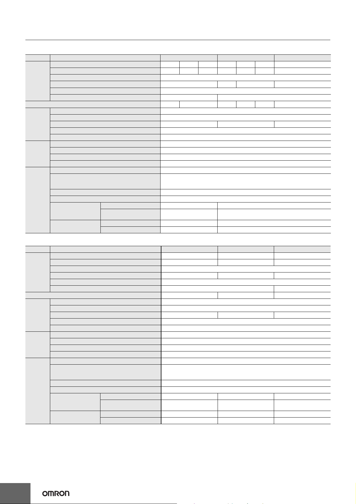
Derating Curves
120
S8JC-Z
100
Load rate (%)
80
60
40
20
0
-20 -10 0 10 20 30 40 50 60 70
Note: 1. Internal parts may occasionally deteriorate or be damaged. Do not use the Power Supply in areas outside the derating curve (i.e., the
area shown by shading A in the above graph).
2. If there is a derating problem, use forced air-cooling.
Ambient Temperature (°C)
A
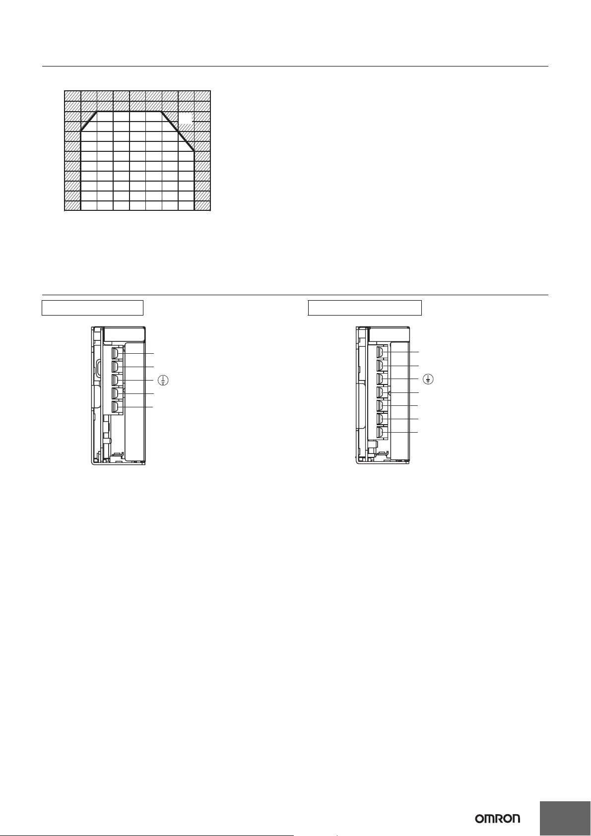
Terminal Arrangement
15-/35-/50-W Models 100-/150-/350-W Models
AC(L)
AC(N)
−V
+V
AC(L)
AC(N)
−V
−V
+V
+V
Note: The S8JC-Z05024C is shown above. Note: The S8JC-Z10024C is shown above.
3
Page 4

S8JC-Z
Dimensions (Unit: mm)
Bottom-mounting Models
S8JC-Z015@@C (15 W)
S8JC-Z035@@C (35 W)
S8JC-Z05024C (50 W)
Panel mounting holes dimensions
Surface screw mounting
Two, M3
Side
Mounting
±0.5
70.5
Bottom
Mounting
Two, M3
70.5
±0.5
±0.5
59.5
±0.5
6.5
36±1
9.5
3.5 dia.
5.5
4.25
4 dia.
30.5
Two , M 3
(Depth 2 mm max.)
3.5
8
20.5
35±0.5
70.5±0.5
79.5±1
4.5
17.5
54±0.5
18
75±1
97±1
65±0.5
45.5
4
24
Note: The screws must not protrude more than 2 mm inside the Power Supply when screw holes provided
on the chassis are used. If the dimensions are not correct, the Power Supply may be damaged.
Panel mounting holes dimensions
98.3±1
33±0.5
Side
Mounting
34
Bottom
13
18±0.5
Mounting
15.5
10.5
Surface screw mounting
Two, M3
±0.5
122.5
Three, M3
±0.5
120
±0.5
85.5
±0.5
13
38±1
9.5
8
4 dia.
5.5
4.5
4 dia.
29
19.5
Three, M3
(Depth 2 mm max.)
129±1
78
32
6.5
77±0.5
S8JC-Z10024C (100 W)
38±1
9.5
8
4 dia.
6
4.5
22 120±0.5
7
4 dia.
31.5
22
22 125±0.5
159±1
149.5±0.5
Three, M3
(Depth 2 mm max.)
Panel mounting holes dimensions
80±0.5
97.6±1
Side
8.7
Mounting
13±0.5
15±0.5
13
16.5
Bottom
Mounting
Surface screw mounting
Two, M3
±0.5
152
±0.5
149.5
Three, M3
±0.5
84
±0.5
15
4
Page 5

S8JC-Z15024C (150 W)
Seven, M3 screws
50±1
4 dia.
S8JC-Z
Four, M3 screws
98
80±0.5
9.5
8
6
4.5
22
120±0.5
159±1
8.7
S8JC-Z35024C (350 W)
7
4 dia.
43.5
29
Three, M3
(Depth 2 mm max.)
22 125±0.5
Panel mounting holes dimensions
Surface screw mounting
Side
Mounting
152
Bottom
Mounting
149.5
±0.5
±0.5
149.5±0.5
Three, M3
Two, M3
26±0.5
13
20
17.5
±0.5
84
±0.5
26
(3)
50±1 (3)
Four, M3
(Depth 2 mm max.)
80±0.5
17.2
115
9.5
8
32.8
25±0.5
13
30
145±0.5
194.8
140±0.5
5
Page 6

S8JC-Z
DIN Rail-mounting Models
S8JC-Z015@@CD (15 W)
S8JC-Z035@@CD (35 W)
S8JC-Z05024CD (50 W)
S8JC-Z10024CD (100 W)
(15.6)
97
5.5
9.5 mm max.
15
98.3
5
9.5 mm max.
9.5
7.8
(3)
46
(3)
46
(10)
9.5
7.8
(10)
79.5
129
97.6
9.5
7.8
46
(3)
(10)
159
(16.1)
5
9.5 mm max.
6
Page 7

S8JC-Z15024CD (150 W)
S8JC-Z35024CD (350 W)
S8JC-Z
97.5
9.5
7.8
(3)
51.5
(10)
159
(16)
5
9.5 mm max.
9.5
7.8
(3)
51.5
(3)
(10)
Safety Precautions
Refer to Safety Precautions for All Power Supplies.
Precautions for Safe Use
• Minor burns may occasionally occur. Do not touch the Product
while power is being supplied or immediately after power is turned
OFF.
• Minor injury due to electric shock may occasionally occur. Do not
touch the terminals while power is being supplied.
• Take adequate measures to ensure proper heat dissipation to
increase the long-term reliability of the Product.
• Connect the ground completely. Electric shock or malfunction may
occur if the ground is not connected completely.
• The service life of the fan is approximately 35,000 hours (at 25°C).
The service life varies, however, depending on the ambient
temperature or other surrounding environmental conditions such
as dust. As a guide two years if it is used at an ambient
temperature of 40°C. (For 350-W Models only.)
• The screws must not protrude more than 2 mm inside the Power
Supply when screw holes provided on the chassis are used.
• Avoid places where the product is subjected to penetration of
liquid, foreign substance, or corrosive gas (in particular, sulfide
gas or ammonia gas).
194.8
(16)
115
5
9 mm max.
7
Page 8

Read and Understand this Catalog
Please read and understand this catalog before purchasing the product. Please consult your OMRON representative if you have any questions
or comments.
Warranty and Limitations of Liability
WARRANTY
OMRON's exclusive warranty is that the products are free from defects in materials and workmanship for a period of one year (or other period
if specified) from date of sale by OMRON.
OMRON MAKES NO WARRANTY OR REPRESENTATION, EXPRESS OR IMPLIED, REGARDING NON-INFRINGEMENT,
MERCHANTABILITY, OR FITNESS FOR PARTICULAR PURPOSE OF THE PRODUCTS. ANY BUYER OR USER ACKNOWLEDGES THAT
THE BUYER OR USER ALONE HAS DETERMINED THAT THE PRODUCTS WILL SUITABLY MEET THE REQUIREMENTS OF THEIR
INTENDED USE. OMRON DISCLAIMS ALL OTHER WARRANTIES, EXPRESS OR IMPLIED.
LIMITATIONS OF LIABILITY
OMRON SHALL NOT BE RESPONSIBLE FOR SPECIAL, INDIRECT, OR CONSEQUENTIAL DAMAGES, LOSS OF PROFITS, OR
COMMERCIAL LOSS IN ANY WAY CONNECTED WITH THE PRODUCTS, WHETHER SUCH CLAIM IS BASED ON CONTRACT,
WARRANTY, NEGLIGENCE, OR STRICT LIABILITY.
In no event shall the responsibility of OMRON for any act exceed the individual price of the product on which liability is asserted.
IN NO EVENT SHALL OMRON BE RESPONSIBLE FOR WARRANTY, REPAIR, OR OTHER CLAIMS REGARDING THE PRODUCTS
UNLESS OMRON'S ANALYSIS CONFIRMS THAT THE PRODUCTS WERE PROPERLY HANDLED, STORED, INSTALLED, AND
MAINTAINED AND NOT SUBJECT TO CONTAMINATION, ABUSE, MISUSE, OR INAPPROPRIATE MODIFICATION OR REPAIR.
Application Considerations
SUITABILITY FOR USE
OMRON shall not be responsible for conformity with any standards, codes, or regulations that apply to the combination of products in the
customer's application or use of the products.
Take all necessary steps to determine the suitability of the product for the systems, machines, and equipment with which it will be used.
Know and observe all prohibitions of use applicable to this product.
NEVER USE THE PRODUCTS FOR AN APPLICATION INVOLVING SERIOUS RISK TO LIFE OR PROPERTY WITHOUT ENSURING THAT
THE SYSTEM AS A WHOLE HAS BEEN DESIGNED TO ADDRESS THE RISKS, AND THAT THE OMRON PRODUCTS ARE PROPERLY
RATED AND INSTALLED FOR THE INTENDED USE WITHIN THE OVERALL EQUIPMENT OR SYSTEM.
PROGRAMMABLE PRODUCTS
OMRON shall not be responsible for the user’s programming of a programmable product, or any consequence thereof.
Disclaimers
CHANGE IN SPECIFICATIONS
Product specifications and accessories may be changed at any time based on improvements and other reasons.
It is our practice to change model numbers when published ratings or features are changed, or when significant construction changes are made.
However, some specifications of the products may be changed without any notice. When in doubt, special model numbers may be assigned to
fix or establish key specifications for your application on your request. Please consult with your OMRON representative at any time to confirm
actual specifications of purchased products.
DIMENSIONS AND WEIGHTS
Dimensions and weights are nominal and are not to be used for manufacturing purposes, even when tolerances are shown.
PERFORMANCE DATA
Performance data given in this catalog is provided as a guide for the user in determining suitability and does not constitute a warranty. It may
represent the result of OMRON’s test conditions, and the users must correlate it to actual application requirements. Actual performance is
subject to the OMRON Warranty and Limitations of Liability.
OMRON Corporation
Industrial Automation Company
Control Devices Division H.Q.
Industrial Component Division
2-2-1 Nishikusatsu, Kusatsu-shi,
Shiga, 525-0035 Japan
Tel: (81) 77-565-5160/Fax: (81) 77-565-5569
Regional Headquarters
OMRON EUROPE B.V.
Wegalaan 67-69-2132 JD Hoofddorp
The Netherlands
Tel: (31)2356-81-300/Fax: (31)2356-81-388
OMRON Industrial Automation Global: www.ia.omron.com
OMRON ELECTRONICS LLC
One Commerce Drive Schaumburg,
IL 60173-5302 U.S.A.
Tel: (1) 847-843-7900/Fax: (1) 847-843-7787
OMRON ASIA PACIFIC PTE. LTD.
No. 438A Alexandra Road # 05-05/08 (Lobby 2),
Alexandra Technopark, Singapore 119967
Tel: (65) 6835-3011/Fax: (65) 6835-2711
OMRON (CHINA) CO., LTD.
Room 2211, Bank of China Tower,
200 Yin Cheng Zhong Road,
PuDong New Area, Shanghai, 200120, China
Tel: (86) 21-5037-2222/Fax: (86) 21-5037-2200
Authorized Distributor:
© OMRON Corporation 2009 All Rights Reserved.
In the interest of product improvement,
specifications are subject to change without notice.
Cat. No. T044-E1-01
Printed in Japan
0909
 Loading...