

Page 1

Uninterruptible Power Supply (UPS)
Control Unit
Battery Unit
S8BA-24D24D□□□SBF
S8BA-S□□□L
User's Manual
S8BA-24D24D480SBF S8BA-S480L
S8BA-24D24D960SBF S8BA-S960L
Page 2

Introduction
Thank you for purchasing OMRON's Uninterruptible Power Supply (UPS).
This manual contains information that is necessary to use the “Uninterruptible Power Supply (UPS)”.
Read this manual carefully and make sure that you understand the functionality and performance of the
product before using it in your system.
Keep this manual in a safe place where it will be available for reference during operation.
Intended audience
This manual is intended for:
Personnel with knowledge of electric systems (the level of knowledge an electrical engineer has or its
equivalent) and at the same time
• Personnel in charge of introducing FA systems
• Personnel in charge of designing FA systems
• Personnel in charge of installing and connecting FA systems
• Personnel in charge of managing FA systems and facilities
Introduction
Applicable products
This manual covers the following products:
• Uninterruptible Power Supply (UPS) S8BA Series
• S8BA-24D24D480SBF
• S8BA-24D24D960SBF
• S8BA-S480L
• S8BA-S960L
Important notice
• No part of this manual may be copied, reproduced, or used in any form without our permission.
• Please be informed that the specifications may be changed without prior notice for the purpose of
improving the contents of this manual.
• We have checked the content of this manual and believe it to be accurate. However, if you find any
errors or have any questions, contact our sales personnel.
At that time, give the Man. No. (manual number) in the back of your manual.
Trademarks
• System names and product names indicated in this manual are registered trademarks or trademarks
of their respective owners.
S8BA Series Uninterruptible Power Supply (UPS) User’s Manual (U726)
1
Page 3
Manual Structure
4-9
4 Installation and Wiring
NJ-series CPU Unit Hardware User’s Manual (W500)
s
t
i
n
U
gnitn
u
oM
3-4
4
s
t
ne
no
p
m
o
C
rel
l
o
r
t
n
oC
g
n
i
tc
e
n
noC
1
-
3-
4
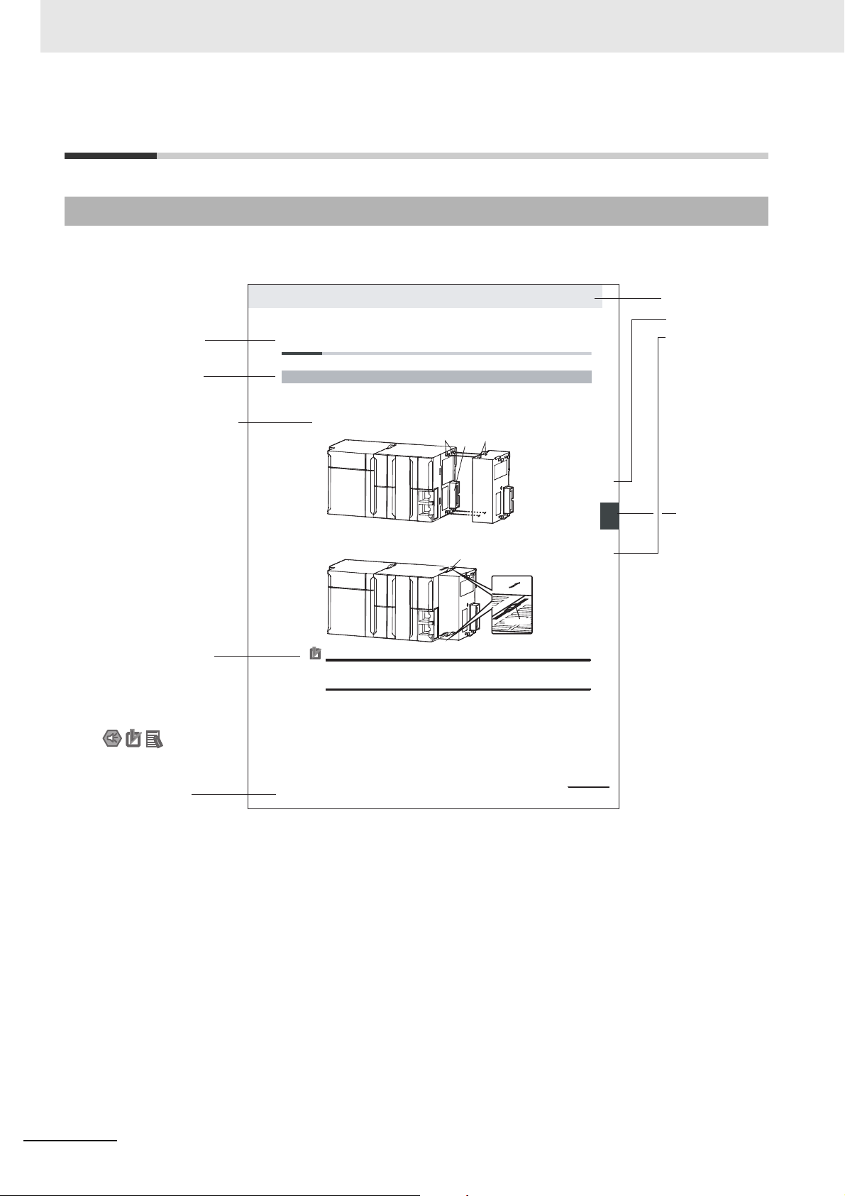
4-3 Mounting Units
The Units that make up an NJ-series Controller can be connected simply by pressing the Units together
and locking the sliders by moving them toward the back of the Units. The End Cover is connected in the
same way to the Unit on the far right side of the Controller.
1 Join the Units so that the connectors fit exactly.
2 The yellow sliders at the top and bottom of each Unit lock the Units together. Move the sliders
toward the back of the Units as shown below until they click into place.
Precautions for Correct UsePrecautions for Correct Use
4-3-1 Connecting Controller Components
Connector
Hook
Hook holes
Slider
Lock
Release
Move the sliders toward the back
until they lock into place.
Level 1 heading
Level 2 heading
Level 3 heading
Level 2 heading
A step in a procedure
Manual name
Special information
Level 3 heading
Page tab
Gives the current
headings.
Indicates a procedure.
Icons indicate
precautions, additional
information, or reference
information.
Gives the numbe
of the main sectio
The sliders on the tops and bottoms of the Power Supply Unit, CPU Unit, I/O Units, Special I/O
Units, and CPU Bus Units must be completely locked (until they click into place) after connecting
the adjacent Unit connectors.
Manual Structure
Page Structure and Icons
The following page structure and icons are used in this manual.
Note This illustration is provided only as a sample. It may not literally appear in this manual.
2
S8BA Series Uninterruptible Power Supply (UPS) User’s Manual (U726)
Page 4
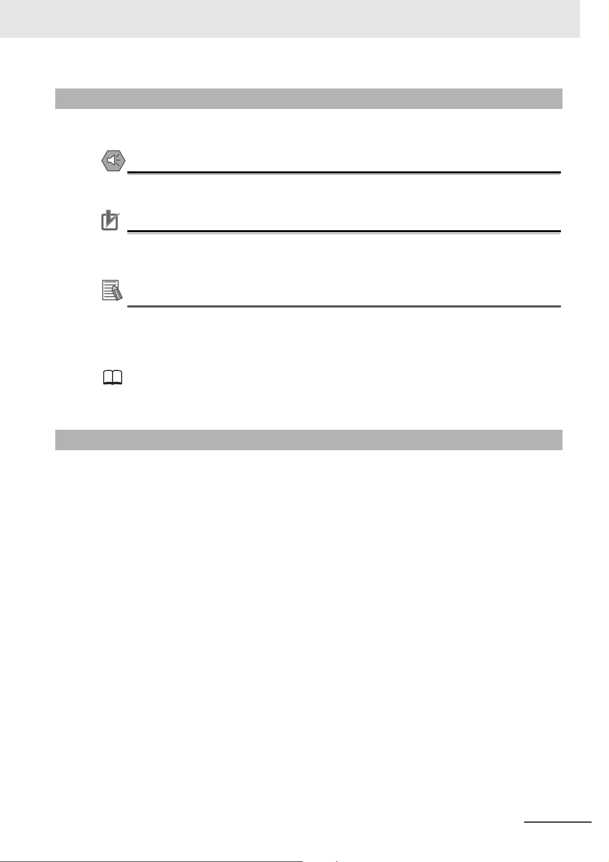
Precautions for Safe Use
Precautions for Correct Use
Additional Information
Special Information
Special information in this manual is classified as follows:
Precautions on what to do and what not to do to ensure safe usage of the product.
Indicates the items to be implemented or avoided when the product is not operating, or to prevent a negative impact on the performance and functions.
Additional information to read as required.
This information is provided to increase understanding or make operation easier.
Manual Structure
References are provided to more detailed or related information.
Points to be Considered Regarding Notations
In this manual, the control unit and battery unit are collectively specified as the "UPS".
The same holds true when "the unit" or "this product" is specified.
Moreover, if the control unit and battery unit are to be indicated individually, they are respectively specified as the "control unit" and "battery unit".
S8BA Series Uninterruptible Power Supply (UPS) User’s Manual (U726)
3
Page 5

Manual Structure
4
S8BA Series Uninterruptible Power Supply (UPS) User’s Manual (U726)
Page 6
1A
2
3
4
5
6
7
8
1A
2
3
4
5
6
7
8
9
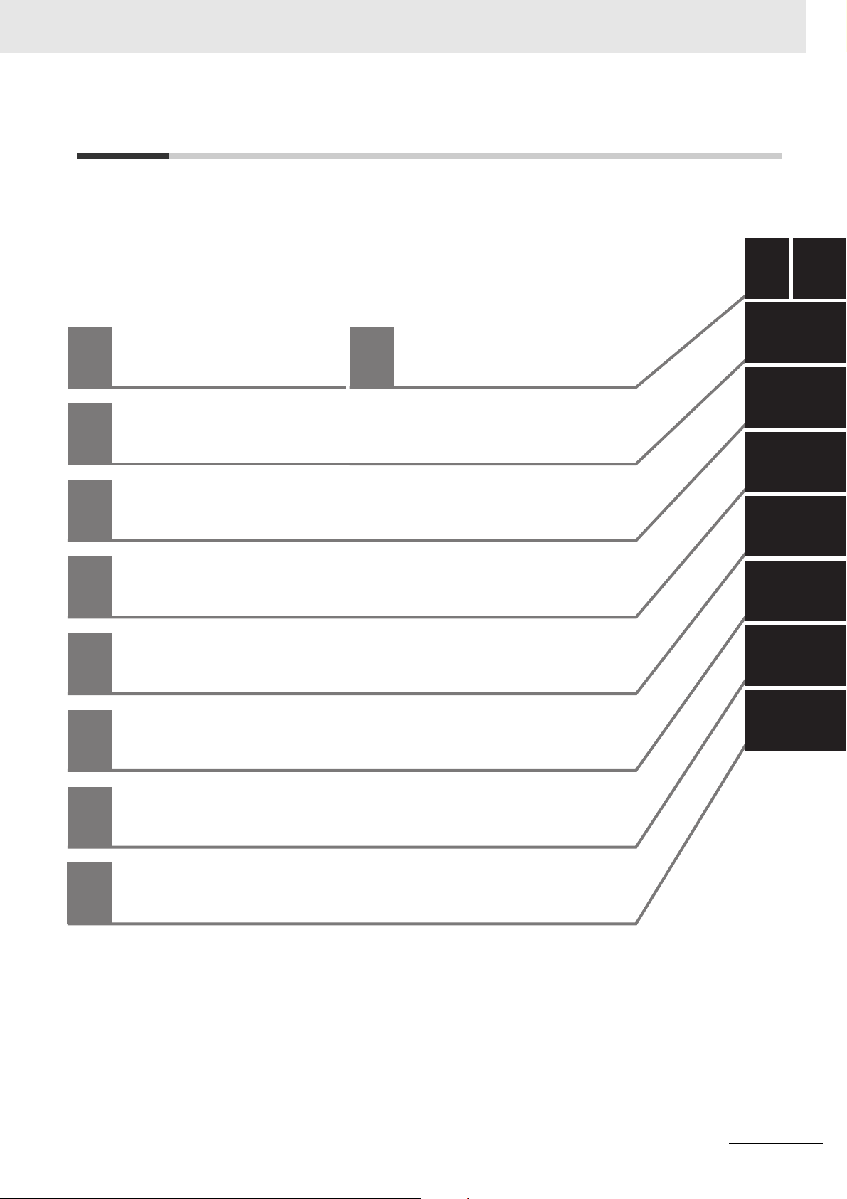
Overview of the product
Preparation
Appendix
I
Installation and connection
Operations
Maintenance and inspection
Using the I/O signal functions
To perform shutdown processing of the devices when a
power failure occurs
Troubleshooting
Table of Contents
Table of Contents
S8BA-series Uninterruptible Power Supply (UPS) User’s Manual (U726)
5
Page 7

CONTENTS
CONTENTS
Introduction .............................................................................................................. 1
Manual Structure...................................................................................................... 2
Table of Contents..................................................................................................... 5
Terms and Conditions Agreement ......................................................................... 8
Safety precautions................................................................................................. 10
Regulations and standards................................................................................... 17
Revision History..................................................................................................... 19
Section 1 Overview of the product
1-1 Features of this product ....................................................................................................... 1-2
1-2 Specifications ........................................................................................................................ 1-3
1-3 Procedure from installation to operation ............................................................................ 1-5
Section 2 Preparation
2-1 Unpacking the product ......................................................................................................... 2-2
2-2 Checking the contents .......................................................................................................... 2-3
2-3 Name of each part ................................................................................................................. 2-4
2-4 Diagram of the Input/output circuit block ........................................................................... 2-6
Section 3 Installation and connection
3-1 Installation.............................................................................................................................. 3-2
3-1-1 DIN rail installation...................................................................................................................... 3-4
3-2 Connection............................................................................................................................. 3-5
3-2-1 UPS connection order................................................................................................................. 3-5
3-2-2 Connecting the UPS control unit and battery unit with a battery connection cable .................... 3-6
3-2-3 Connecting a device to the output terminal block ....................................................................... 3-8
3-2-4 Connecting the input power supply to the input terminal block................................................... 3-8
3-2-5 Connecting a cable to the battery terminal block, input terminal block and output terminal block....
3-9
Section 4 Operations
4-1 Checking the operation......................................................................................................... 4-2
4-1-1 LED display................................................................................................................................. 4-2
4-1-2 Backup operation time setting / Battery replacement mode selection switch ............................. 4-5
4-2 Start and stop procedures and basic operation................................................................. 4-6
4-2-1 Start and stop procedures........................................................................................................... 4-6
6
S8BA-series Uninterruptible Power Supply (UPS) User’s Manual (U726)
Page 8

CONTENTS
Section 5 Maintenance and inspection
5-1 Inspecting the battery ........................................................................................................... 5-2
5-1-1 Expectancy of the battery ........................................................................................................... 5-2
5-1-2 Estimated backup time ............................................................................................................... 5-2
5-2 Replacing the battery unit .................................................................................................... 5-4
5-2-1 Notification that the battery unit needs to be replaced................................................................ 5-4
5-2-2 Procedure for replacing the battery unit...................................................................................... 5-6
5-3 Cleaning the Unit ................................................................................................................... 5-9
Section 6 To perform shutdown processing of the devices when a
power failure occurs
6-1 The outline on the UPS monitoring software...................................................................... 6-2
6-1-1 UPS monitoring software............................................................................................................ 6-2
6-1-2 How to connect........................................................................................................................... 6-2
Section 7 Using the I/O signal functions
7-1 I/O signal functions ............................................................................................................... 7-2
7-1-1 Type of output signals................................................................................................................. 7-2
7-1-2 Type of input signals................................................................................................................... 7-2
7-1-3 CONTACT port (RJ45 connector)............................................................................................... 7-3
7-1-4 Contact signal ratings ................................................................................................................. 7-3
7-1-5 Contact signal circuit................................................................................................................... 7-3
7-1-6 Precautions and notes for the use of the I/O signal functions .................................................... 7-4
7-1-7 Example of the use of the Contact Signal circuit ........................................................................ 7-4
Section 8 Troubleshooting
8-1 Troubleshooting .................................................................................................................... 8-2
Appendix
A-1 Dimensions ............................................................................................................................A-2
A-2 Characteristic data ................................................................................................................A-5
A-2-1 Derating curve ............................................................................................................................A-5
A-2-2 Overcurrent protection curve ......................................................................................................A-6
S8BA-series Uninterruptible Power Supply (UPS) User’s Manual (U726)
7
Page 9

Terms and Conditions Agreement
Terms and Conditions Agreement
Warranty, Limitations of Liability
Warranties
z Exclusive Warranty
Omron’s exclusive warranty is that the Products will be free from defects in materials and workmanship for a period of twelve months from the date of sale by Omron (or such other period expressed in
writing by Omron). Omron disclaims all other warranties, express or implied.
z Limitations
OMRON MAKES NO WARRANTY OR REPRESENTATION, EXPRESS OR IMPLIED, ABOUT
NON-INFRINGEMENT, MERCHANTABILITY OR FITNESS FOR A PARTICULAR PURPOSE OF
THE PRODUCTS. BUYER ACKNOWLEDGES THAT IT ALONE HAS DETERMINED THAT THE
PRODUCTS WILL SUITABLY MEET THE REQUIREMENTS OF THEIR INTENDED USE.
Omron further disclaims all warranties and responsibility of any type for claims or expenses based
on infringement by the Products or otherwise of any intellectual property right.
z Buyer Remedy
Omron’s sole obligation hereunder shall be, at Omron’s election, to (i) replace (in the form originally
shipped with Buyer responsible for labor charges for removal or replacement thereof) the non-complying Product, (ii) repair the non-complying Product, or (iii) repay or credit Buyer an amount equal
to the purchase price of the non-complying Product; provided that in no event shall Omron be
responsible for warranty, repair, indemnity or any other claims or expenses regarding the Products
unless Omron’s analysis confirms that the Products were properly handled, stored, installed and
maintained and not subject to contamination, abuse, misuse or inappropriate modification. Return of
any Products by Buyer must be approved in writing by Omron before shipment. Omron Companies
shall not be liable for the suitability or unsuitability or the results from the use of Products in combination with any electrical or electronic components, circuits, system assemblies or any other materials or substances or environments. Any advice, recommendations or information given orally or in
writing, are not to be construed as an amendment or addition to the above warranty.
See http://www.omron.com/global/ or contact your Omron representative for published information.
Limitation on Liability; Etc
OMRON COMPANIES SHALL NOT BE LIABLE FOR SPECIAL, INDIRECT, INCIDENTAL, OR CONSEQUENTIAL DAMAGES, LOSS OF PROFITS OR PRODUCTION OR COMMERCIAL LOSS IN ANY
WAY CONNECTED WITH THE PRODUCTS, WHETHER SUCH CLAIM IS BASED IN CONTRACT,
WARRANTY, NEGLIGENCE OR STRICT LIABILITY.
Further, in no event shall liability of Omron Companies exceed the individual price of the Product on
which liability is asserted.
8
S8BA-series Uninterruptible Power Supply (UPS) User’s Manual (U726)
Page 10

Application Considerations
Suitability of Use
Omron Companies shall not be responsible for conformity with any standards, codes or regulations
which apply to the combination of the Product in the Buyer’s application or use of the Product. At
Buyer’s request, Omron will provide applicable third party certification documents identifying ratings
and limitations of use which apply to the Product. This information by itself is not sufficient for a complete determination of the suitability of the Product in combination with the end product, machine, system, or other application or use. Buyer shall be solely responsible for determining appropriateness of
the particular Product with respect to Buyer’s application, product or system. Buyer shall take application responsibility in all cases.
NEVER USE THE PRODUCT FOR AN APPLICATION INVOLVING SERIOUS RISK TO LIFE OR
PROPERTY OR IN LARGE QUANTITIES WITHOUT ENSURING THAT THE SYSTEM AS A WHOLE
HAS BEEN DESIGNED TO ADDRESS THE RISKS, AND THAT THE OMRON PRODUCT(S) IS
PROPERLY RATED AND INSTALLED FOR THE INTENDED USE WITHIN THE OVERALL EQUIPMENT OR SYSTEM.
Terms and Conditions Agreement
Programmable Products
Omron Companies shall not be responsible for the user’s programming of a programmable Product, or
any consequence thereof.
Disclaimers
Performance Data
Data presented in Omron Company websites, catalogs and other materials is provided as a guide for
the user in determining suitability and does not constitute a warranty. It may represent the result of
Omron’s test conditions, and the user must correlate it to actual application requirements. Actual performance is subject to the Omron’s Warranty and Limitations of Liability.
Change in Specifications
Product specifications and accessories may be changed at any time based on improvements and other
reasons. It is our practice to change part numbers when published ratings or features are changed, or
when significant construction changes are made. However, some specifications of the Product may be
changed without any notice. When in doubt, special part numbers may be assigned to fix or establish
key specifications for your application. Please consult with your Omron’s representative at any time to
confirm actual specifications of purchased Product.
Errors and Omissions
Information presented by Omron Companies has been checked and is believed to be accurate; however, no responsibility is assumed for clerical, typographical or proofreading errors or omissions.
S8BA-series Uninterruptible Power Supply (UPS) User’s Manual (U726)
9
Page 11
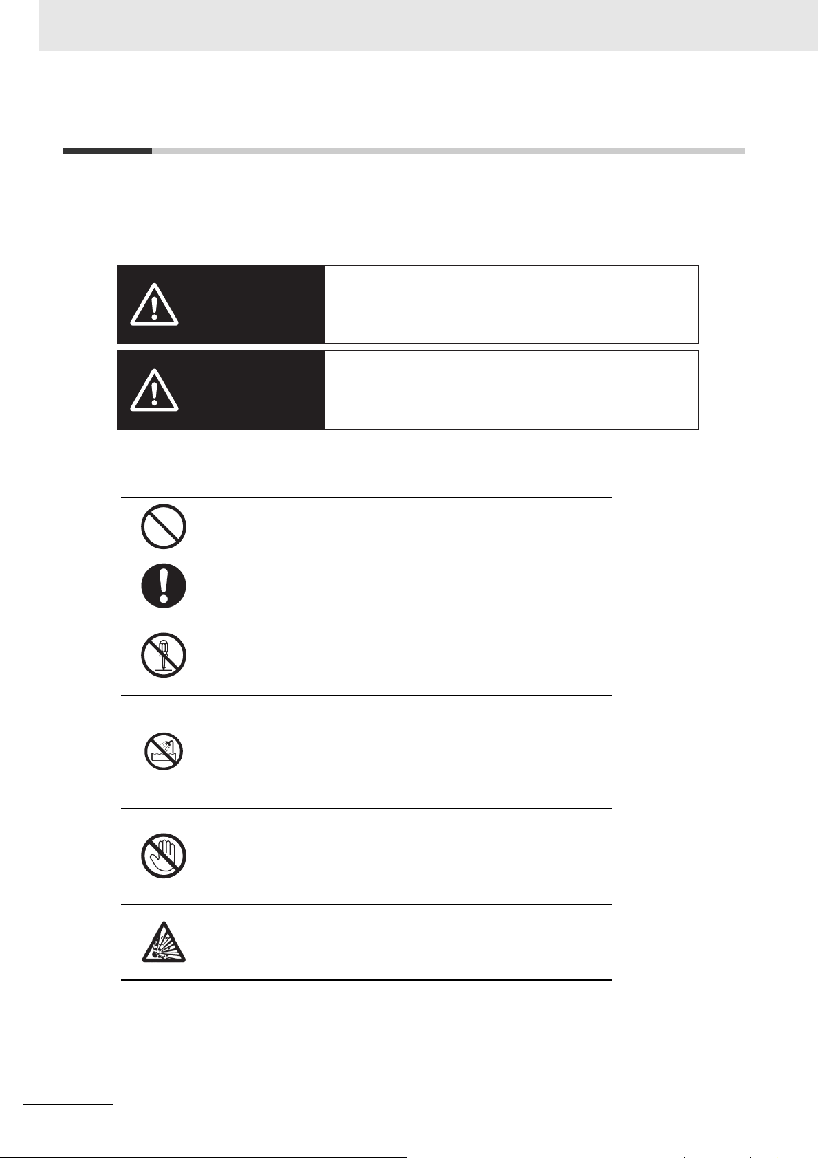
Safety precautions
WARNING
Caution
If you fail to use the product properly, it may result in injuries, mild
or moderate, and may lead to death. Additionally, there may be
severe property damage.
If you fail to use the product properly, it may result in injuries, mild
or moderate, or damage on property.
Safety precautions
Important information for safe operation is described.
Be sure to read it before installation and start of use.
The safety symbols and their meaning used in this manual are as follows:
*Property damage means damage to houses/household effects, livestock, and pets.
●Meaning of graphical symbols
●General inhibition
Notice prohibiting an unspecified general action.
●General instruction
Notice instructing an unspecified general action.
●Do-not-disassemble prohibition
Notice prohibiting disassembly.
Disassembling the unit may lead to electric shock or other accidents.
●Prohibition of use in locations subject to water such as a bathroom and
shower room.
Notice prohibiting exposure to water.
Using a unit without waterproofing in locations subject to water may
result in accidents due to electric shock.
●Do-not-touch prohibition
Notice prohibiting touching.
Under specific conditions, touching the unit at specific locations could
result in accidents.
Note that events categorized as a caution required matter also may cause more serious results under
certain conditions.
10
The information described here is very important and must be strictly observed.
●Explosion alert
Notice alerting the user to the possibility of explosion under certain conditions.
S8BA-series Uninterruptible Power Supply (UPS) User’s Manual (U726)
Page 12
Warning
WARNING
Caution
For use of this product
• Provide safety measures outside the UPS to ensure safety in the entire system even if
the UPS is damaged or an abnormality occurs due to an external factor. Not doing so
may result in serious accidents due to incorrect operation.
Wiring
Do not short between the connector terminals.
• Doing so may result in electric shock.
• The battery unit's protection board may be damaged due to a short-circuit.
• Connect each connection cable to the correct connected device.
• Connect the terminal of each connection cable to the connector port with correct polarity.
• Be sure to follow the connection procedure described in 3-2-2 Connecting the UPS con-
trol unit and battery unit with a battery connection cable on page 3-6.
Safety precautions
When the Battery Unit is Replaced
Dispose of or collect (recycle) the battery unit according to your own rules set for that purpose or as instructed by laws and regulations.
• Do not dispose of it in fire. Otherwise, it could explode.
Caution
For installation and connection
Pay attention to the weight and balance when carrying the unit, and install it in a solid and
stable location.
• Do not drop the battery unit and do not expose it to strong impact. Dropping the unit may
• If you drop the unit, have it inspected and repaired. For repairs, contact our sales person-
Keep plastic package bags out of reach of children.
• Children may suffocate if they place their heads into plastic bags.
result in injury or fire.
nel.
S8BA-series Uninterruptible Power Supply (UPS) User’s Manual (U726)
11
Page 13
Safety precautions
• Voltage range: 23 to 28 V DC
Be sure to connect the input power supply of the unit to a DC power supply device having a
rated voltage (24 VDC), or a battery power feed system.
• The input voltage ranges for the UPS are as shown below. Check that the output voltage
of the DC power supply device connected to the input terminal of the UPS is within any of
the voltage ranges below.
• Connecting to a DC or AC power supply device with a different voltage may result in malfunction in or damage to the UPS, or cause a fire.
When an abnormality (unusual sound or smell) occurs, turn OFF the unit’s “Power” switch
to stop the output, and stop the supply of commercial power.
To make an emergency stop, turn the rotary switch to "BATT REP" and turn off the input
power after the LED changes from fast blinking to slow blinking.
• When performing maintenance on the connected devices, follow the above instructions
to ensure safety.
When installing the input cable, make sure to perform the connection as specified.
Make sure to stop the primary power supply before connecting the unit to the input power
supply terminal.
• When connecting a cable to the terminal block, use a cable that complies with the input
current specification of the UPS. Failure to do so may result in electric shock or ground
fault.
Do not disassemble, repair, or modify the unit.
• Doing so may cause an electric shock or a fire.
Do not install the unit in other than specified orientations.
• Dropping or toppling the unit may cause injury.
• If you install the unit in an orientation other than specified, the internal temperature may
rise, eventually damaging the UPS or deteriorating the battery.
Do not use the unit at a location where the operating environment temperature is more than
55°C.
• The battery deteriorates rapidly. It may result in fire.
• If the battery's resin separator is damaged, the battery may be short-circuited inside, and
may cause an abnormal heating, smoke, rupture or fire.
• Doing so may cause a failure or malfunction of the unit.
Do not exceed the ranges specified for environmental conditions during use/storage.
Do not install or store the unit in the places listed below.
• Do not store in places where the humidity is lower than 10% or higher than 90%.
• Do not use the unit in places where the ambient temperature is lower than 0°C or higher
than 55°C. (With no condensation)
• Do not use in places where the humidity is lower than 10% or higher than 90%.
• Do not install/store the unit in closed places such as cabinets with no clearance, places
where there is flammable or corrosive gas, places with large amounts of dust, places
exposed to direct sunlight, places exposed to shock or vibration, salty or wet places, or
outdoors.
• Installation or storing the unit in such a place may cause a fire.
When you use plug strip and other plugs to connect additional devices, do not connect
devices that exceed the current capacity of the available plugs.
• The current protection of the unit may operate, which may stop the output.
• The cable heats up, which may cause a fire.
12
S8BA-series Uninterruptible Power Supply (UPS) User’s Manual (U726)
Page 14
Safety precautions
Ambient
temperature
Expected
life
*The values in the table are the expected
life under standard use conditions and
are not guaranteed.
25°C 10 years
35°C 6.7 years
45°C 3.7 years
55°C 1.9 years
Do not use a cable with damaged insulation.
Do not pinch or sharply bend the cable.
Do not fold or knot the cable.
• Doing so may cause the cable to be damaged or heated, which may cause an electric
shock or a fire.
• If the cable is damaged, stop using the unit and have the cable repaired.
• For repair, contact our sales personnel.
Do not connect any devices other than rated voltage is 24 VDC.
• The rated output voltage of this unit is 24 VDC.
• Overvoltage or overcurrent may damage the connected devices.
• The output voltage range is 22 to 30 VDC.
All of the included accessories are designed to be used with the unit. Do not use the accessories with other devices.
• Doing so may compromise the safety of devices.
When this product is used in compliance with CE marking, please use under 2 m communication cable.
Do not block the air vents (upper and lower).
• Doing so will cause the internal temperature to rise, which may cause the unit to fail and
the battery to deteriorate.
• During installation, leave a space of 50 mm or more above the top and below the bottom.
Do not connect the RS232C/USB port or the CONTACT port to a LAN device using a LAN
cable.
• Connection to a LAN device may result in malfunction in or damage to the UPS or the
LAN device.
Do not run this unit in parallel.
• Operating this unit in parallel may cause a failure or malfunction.
For use
Do not allow the unit to come in contact with water.
• Doing so may cause an electric shock or a fire.
• Doing so may cause an abnormal heating, smoke, rupture, or fire on the battery.
• If the unit comes in contact with water, immediately stop using it and have it inspected
and repaired. To make an emergency stop, turn the rotary switch to "BATT REP" and turn
off the input power after the LED changes from fast blinking to slow blinking.
• For repair, contact our sales personnel.
When the battery unit is dead, replace it immediately or stop using the unit.
• Continuing the use of it may cause fire or electric shock due to liquid leaks.
S8BA-series Uninterruptible Power Supply (UPS) User’s Manual (U726)
13
Page 15
Safety precautions
Occasionally, wipe off dust on the input terminal block and the output terminal block with a
dry cloth.
• Accumulated dust may cause a fire.
Before wiping off dust, stop all connected devices and the unit, and stop the supply of commercial power.
The unit will stop after 30 seconds of setting the mode selection/backup operation time
selection switch to "0.5".
Do not use the unit in a closed place and do not cover the unit.
• Doing so may cause abnormal heating or a fire.
If you notice something unusual such as abnormal sound or smell, discoloration, deformation, and heating, turn OFF the unit's power and stop the supply from the input power supply.
To make an emergency stop, turn the rotary switch to "BATT REP" and turn off the input
power after the LED changes from fast blinking to slow blinking.
• Using the unit under such conditions may cause an abnormal heating, rupture or fire.
• If you notice such a condition, stop using the unit and contact our sales personnel for
inspection and repairs.
If fluid leaks from the interior, do not touch the fluid.
• Doing so may cause blindness or burns.
• If the fluid contacts your eyes or skin, wash it out with lots of clean water and consult your
doctor. The fluid may damage your eye if your eye is left untreated.
Do not place any objects on the unit, and do not drop heavy objects onto the unit.
• Doing so may cause distortion/damage to the case or a failure of the internal circuit,
which may cause a fire.
The unit is equipped with an output circuit that can supply power to the connected devices
even if the unit stops due to a failure or mis-operation of the internal circuit function.
If you want to stop the output, stop the source of the “input power supply”.
• Output is continuing even when all indicators of the front panel are off.
When charging the battery, if the battery cannot be charged completely even after the predetermined charging time, turn OFF the "Power" switch of the unit to stop charging the battery.
The unit will stop after 30 seconds of setting the mode selection/backup operation time
selection switch to "0.5".
• Otherwise, it may cause an abnormal heating, smoke, rupture or fire on the battery.
14
For maintenance
When performing maintenance of the connected equipment, turn OFF the unit's power and
stop the supply from the input power supply.
The unit will stop after 30 seconds of setting the mode selection/backup operation time
selection switch to "0.5".
• Even if the input power supply is stopped in the operating state, the power supply output
of the unit will not stop, and power will be supplied from the battery.
Do not disassemble, repair, or modify the unit.
• Doing so may cause an electric shock or a fire.
If fluid leaks from the interior, do not touch the fluid.
• Doing so may cause blindness or burns.
• If the fluid contacts your eyes or skin, wash it out with lots of clean water and consult your
doctor.
S8BA-series Uninterruptible Power Supply (UPS) User’s Manual (U726)
Page 16
Do not throw the unit into fire.
• Since the battery is incorporated in the unit, the insulator may melt, the gas exhaust valve
or protection mechanism may be damaged, or the electrolyte may catch fire, and it may
result eventually in an abnormal heating, smoke, rupture or fire.
Do not insert metal objects into the input terminal block and the output terminal block of the
UPS.
• Doing so may result in electric shock.
Do not insert metal objects into the battery connectors. Do not short between the connector
terminals.
• Doing so may result in electric shock.
• The battery unit's protection board may be damaged due to a short-circuit.
When the Battery Unit is Replaced
Do not use other than the designated battery unit.
• Not doing so may cause a fire.
• Product model: S8BA-S480L, S8BA-S960L
Do not replace the battery unit in a place where there is flammable gas.
• Spark may occur when connecting the battery unit, which may cause an explosion or fire.
Safety precautions
If fluid leaks from the battery unit, do not touch the fluid.
• Doing so may cause blindness or burns.
• If the fluid contacts your eyes or skin, wash it out with lots of clean water and consult your
doctor.
Do not disassemble or modify the battery unit.
• A safety mechanism and protection mechanism to prevent danger are embedded into the
battery unit. If these are damaged, it may cause the battery to emit heat, smoke, explode,
or catch fire.
Do not drop the battery unit and do not expose it to strong impact.
Dropping the unit may result in injury or fire.
• Doing so may cause a leakage, abnormal heating, smoke, rupture or fire on the battery
unit. And, if the battery unit's protection mechanism is broken, the battery may be
charged at an abnormal current or voltage, an abnormal chemical reaction may occur
inside the battery, and it may result eventually in an abnormal heating, smoke, rupture or
fire.
Do not short the battery unit with metal objects.
• Doing so could cause an electric shock, fire or burn.
• Some electrical energy still remains inside the spent battery unit.
Do not dispose of battery units in a fire.
• The insulator inside the battery unit may melt, the gas exhaust valve or protection mech-
anism may be damaged, or the electrolyte may catch fire, and it may result eventually in
abnormal heating, smoke, rupture or fire.
S8BA-series Uninterruptible Power Supply (UPS) User’s Manual (U726)
15
Page 17

Safety precautions
Important Safety Points
■ Before using
• The battery has not been charged at the time of purchase. Be sure to charge it before use.
• Connect this unit to the input power supply to charge the battery unit.
When moving the unit from a cold place to a warm place, leave it for several hours before using it.
• If the unit is promptly turned ON after being moved to a warmer place, condensation may form inside
the unit and cause it to fail.
Take measures for handling unforeseen accidents, such as data backup and system redundancy.
• The output may stop when there is failure in this unit.
■ Connecting
Do not short the unit output lines together, and do not short the battery connection cable (to ground).
• The unit may fail.
In the event you transfer or sell this unit to a third party, please include all of the documentation that came
with the unit. This is to ensure that the unit is used in line with the conditions described in the included
documentation.
• This manual contains important safety-related information. Please read and understand the contents of
the manual before beginning operation. If this manual is misplaced, download the manual from our
website.
■ Using
Before stopping the commercial power to the unit, turn OFF the “Power” switch of the unit.
The unit will stop after 30 seconds of setting the mode selection/backup operation time selection switch to
"0.5".
• The unit enters Battery Mode when input power supply is stopped.
• If the frequency of backup operation becomes high, the battery life may be significantly reduced.
Do not use for an application that frequently requires Battery Mode.
• The battery unit will deteriorate and fail to maintain the specified backup time.
If you want the UPS to stand by in a UPS startup state, set 3 months or less for the input power supply
stop period.
• The UPS startup state means the state of waiting for startup triggered by a remote ON/OFF or BS signal.
• If the UPS is left unused in the above state for 3 months or longer, the battery goes into overdischarge
state, and the backup time may become shorter or the battery may become unusable.
■ Storing
Storing the battery in UPS for a long term, store at an environment less than 25°C and recharge 15 to 30
minutes the battery within 1 year.
• The battery self-discharges even when it not being used, and it goes into overdischarge state if it is left
for a long period of time. The backup time may become shorter or the battery may become unusable.
• We recommend keeping the temperature 25°C or less when storing the unit for long periods of time.
• Turn OFF the unit’s power when storing it.
Do not install or store the unit in a place exposed to direct sunlight.
• The rise of temperature may cause the battery unit to deteriorate rapidly and become unusable.
16
S8BA-series Uninterruptible Power Supply (UPS) User’s Manual (U726)
Page 18

Regulations and standards
Use overseas
To export (or provide to non-residents of Japan) a model of this product that is categorized as a merchandise (or technology) requiring the export permission and approval stipulated by the Foreign
Exchange and Foreign Trade Law, the export permission and approval (or service transaction permission) in accordance with the said law are required.
Conformance to each Directive
z Applicable directives
• EMC Directives
Regulations and standards
z Principles regarding conformance
OMRON electronic devices that comply with EC Directives also conform to the related EMC standards so that they can be more easily built into other devices or the overall machine. The actual
*
products have been checked for conformity to EMC standards
Whether the products conform to the standards in the system used by the customer, however, must
be checked by the customer. EMC-related performance of the OMRON devices that comply with EC
Directives will vary depending on the configuration, wiring, and other conditions of the equipment or
control panel on which the OMRON devices are installed. The customer must, therefore, perform
the final check to confirm that devices and the overall machine conform to EMC standards.
*1. Applicable EMC (Electromagnetic Compatibility) standards are as follows: EMS (Electromagnetic Susceptibil-
ity): EN 61000-6-2, EMI (Electromagnetic Interference): EN 61000-6-4, and EN 61000-6-4 Radiated emission: 10-m regulations
.
z Conformance to EC Directives
This product complies with EC Directives. To ensure that the machine or device in which the this
product is used complies with EC Directives, the product must be installed as follows:
• This product must be installed within a control panel.
• You must use reinforced insulation or double insulation for the direct power supply equipment
connected to this product.
• Models of this product that comply with EC Directives also conform to the Common Emission
Standard. Radiated emission characteristics (10-m regulations), in particular, may vary depending
on the configuration of the control panel used, other devices connected to the control panel, wiring, and other conditions. Therefore, even when using a model of this product that complies with
EC Directives, you must confirm and ensure the compliance to EC Directives of the entire
machine or equipment.
• This is a Class A product (for industrial environments). In a residential environment, it may cause
radio interference. If radio interference occurs, the user may be required to take appropriate measures.
z Conformance to UL
• This product must be installed within a control panel with an internal heater or other unit to protect
against the formation of condensation (Standard mounting only).
• Gaps in the door to the control panel must be completely filled or covered with gaskets or other
material.
• For use in Pollution Degree 2 Environment.
S8BA-series Uninterruptible Power Supply (UPS) User’s Manual (U726)
17
Page 19

Regulations and standards
Precautions for Safe Use
• Surrounding Air Temperature, 55°C.
• Make sure to connect the device with Class 2 output to the USB port.
z Conformance to FCC
• FCC CAUTION
Changes or modifications not expressly approved by the party responsible for compliance could
void the user’s authority to operate the equipment.
This equipment has been tested and found to comply with the limits for a Class A digital device,
pursuant to part 15 of the FCC Rules. These limits are designed to provide reasonable protection against harmful interference when the equipment is operated in a commercial environment.
This equipment generates, uses, and can radiate radio frequency energy and, if not installed
and used in accordance with the instruction manual, may cause harmful interference to radio
communications. Operation of this equipment in a residential area is likely to cause harmful
interference in which case the user will be required to correct the interference at his own
expense.
18
S8BA-series Uninterruptible Power Supply (UPS) User’s Manual (U726)
Page 20
Revision History
A manual revision code appears as a suffix to the catalog number on the front and back covers of the
manual.
Revision History
U726-E1-01
Revision code
Revision
code
01 March 2018 Original production
Date Revised content
S8BA-series Uninterruptible Power Supply (UPS) User’s Manual (U726)
19
Page 21

Revision History
20
S8BA-series Uninterruptible Power Supply (UPS) User’s Manual (U726)
Page 22

3
Overview of the product
This section describes the characteristics and specifications of the product.
1-1 Features of this product . . . . . . . . . . . . . . . . . . . . . . . . . . . . . . . . . . . . . . . . 1-2
1-2 Specifications . . . . . . . . . . . . . . . . . . . . . . . . . . . . . . . . . . . . . . . . . . . . . . . . . 1-3
1-3 Procedure from installation to operation . . . . . . . . . . . . . . . . . . . . . . . . . . . 1-5
1
S8BA-series Uninterruptible Power Supply (UPS) User’s Manual (U726)
1 - 1
Page 23

1 Overview of the product
1-1 Features of this product
• The Uninterruptible Power Supply (UPS) protects such devices as PLC and IPC* from power failures,
voltage variations, and instantaneous voltage drops.
• Under normal conditions, the UPS outputs 24 VDC of electrical power from the DC power supply
as-is. When an abnormality is detected in the 24 VDC power supply such as a power failure and voltage variation, the UPS switches to battery supply to continue to provide 24 VDC of electrical power.
• For the specifications of PLC and IPC for power supply input and operation in the event of momentary power interruptions, check the respective manuals.
*IPC: Industrial PC (Industrial use computer)
List of models
The product has the following models:
Unit model Specifications
S8BA-24D24D480SBF Control unit (480 W)
S8BA-24D24D960SBF Control unit (960 W)
S8BA-S480L Battery unit (for 480 W)
S8BA-S960L Battery unit (for 480 W / 960 W)
Note The control unit (960 W) and battery unit (480 W) cannot be connected.
1 - 2
S8BA-series Uninterruptible Power Supply (UPS) User’s Manual (U726)
Page 24
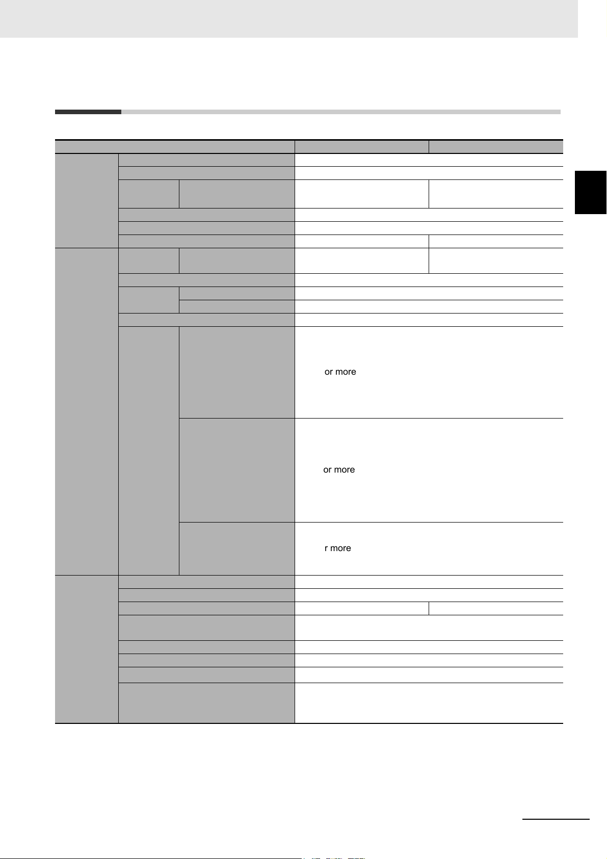
1-2 Specifications
1 Overview of the product
Description Capacity 480 W 960 W
DC input Rated input voltage 24 VDC
Input voltage range 23 to 28 VDC
Input maximum current
Input terminal Push-in terminal block
Input protection Fuse (cannot be replaced by the customer)
Input protection capacity 30 A 60 A
DC output Rated cur-
rent
Switching time Uninterrupted
Output volt-
age
Output terminal Push-in positive terminal block
Overload
protection
Battery unit Type Lithium-ion battery
Rated voltage 25.2 VDC
Rated capacity 3900 mAh 7800 mAh
Battery life expectancy 10 years (25°C), 6.7 years (35°C), 3.7 years (45°C), 1.9 years
Replacement by user Yes (Hot swapping)
Battery Life Counter Function Yes
Charging time
Backup time (25°C, initial characteristics) 6 min. (constant power rated load)
for rated input voltage
for rated loads connected
for rated output voltage 20 A 40 A
Normal operation Input voltage through output 22 to 30 VDC
Backup operation 21 to 28 V (the voltage cannot be adjusted)
Warning display
• UPS output will continue
through bypass [during
normal operation]
• UPS output will continue
through battery [during
backup operation]
Output stopped by overload protection
• Stop output [during normal operation]
• The internal power supply to the UPS will stop
after 10 sec. [during
backup operation]
Warning display cancellation
(During normal operation,
during backup operation)
21.5 A 43.5 A
101% or more
111% or more
93% or more
(55°C)
8 hours (90%)
The backup time can be set from the mode selection / backup
operation time selection switch, or the shutdown software.
*1
1
S8BA-series Uninterruptible Power Supply (UPS) User’s Manual (U726)
1 - 3
Page 25
1 Overview of the product
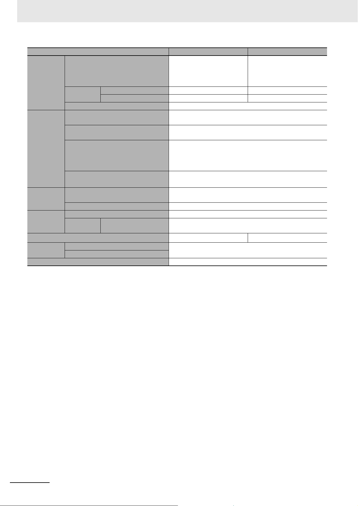
Description Capacity 480 W 960 W
Structure Dimensions (W×H×D mm) 44 × 124 × 111.4 (UPS control
unit 20 A)
80 × 124 × 111.4 (battery unit
20 A)
Weight Weight of control unit Approx. 0.6 kg Approx. 0.7 kg
Weight of battery unit Approx. 1.5 kg Approx. 2.5 kg
Cooling method Natural cooling
Environment Operating environment temperature /
0°C to 55°C / 10% to 90%RH with no condensation
humidity
Storage environment temperature /
−20°C to 55°C / 10% to 90%RH with no condensation
humidity
Vibration resistance JIS C 60068-2-6 compliant
5 to 8.4Hz amplitude: 3.5mm, 8.4 to 150Hz
acceleration rate: 9.8m/s
2
(Sweep time: 10min.×Sweep count 10 times=Total: 100min.)
Shock resistance
JIS C 60068-2-27 compliant: 147m/s
three times
Dielectric
breakdown
voltage
Standard
compliance
Withstand voltage DC external terminals to casing: 510 V AC, 1 minute, leakage
current 5 mA max.
Insulation resistance DC external terminals to casing: 20 MΩ or more. (500 V DC)
Safety standard UL508 / CE / C22.2 No.107.1-01
EMI Radiation disturbance
EN61000-6-4 / FCC / ICES / RCM
field strength
Internal power consumption (normal*2 / maximum)
Serial com-
munication
RS232C (Interface terminal) Yes (RJ45)
USB (Interface terminal)
7 W / 29 W 15 W / 58 W
I/O signal (Interface terminal) Yes (RJ45)
*1. When using in an environment at a high temperature, charging may be paused by charging temperature protection, then
the charging time will be longer than specified time.
*2. Conditions: With rated loads connected, at a rated input voltage, and at a full battery charge.
52 × 124 × 111.4 (UPS control
unit 40 A)
150 × 124 × 111.4 (battery unit
40 A)
X, Y, and Z directions: 100min.
2
X, Y, and Z directions
1 - 4
S8BA-series Uninterruptible Power Supply (UPS) User’s Manual (U726)
Page 26

1 Overview of the product
Start
Read “Safety Precautions”
Page 10
Remove the product from the
package and check the contents
2. Preparation
Perform installation and connection
3. Installation and connection
Are you using either of the
following functions?
- Automatic shutdown software
- I/O signal functions
6. To perform shutdown processing of the
devices when a power failure occurs
7. Using the I/O signal functions
Check the operation
4. Operations
Operate
4. Operations
Perform maintenance and inspection
5. Maintenance and Inspection
Replace the battery unit
5.2 Replacing the battery
The battery unit must
be replaced
Installation/connection
Preparation for operation
Operate
Perform maintenance
and inspection
Yes
No
No
Yes
1-3 Procedure from installation to operation
The procedure from installation to operation is shown below.
1
S8BA-series Uninterruptible Power Supply (UPS) User’s Manual (U726)
1 - 5
Page 27

1 Overview of the product
1 - 6
S8BA-series Uninterruptible Power Supply (UPS) User’s Manual (U726)
Page 28

Preparation
This section describes the preparations for using the product.
2-1 Unpacking the product . . . . . . . . . . . . . . . . . . . . . . . . . . . . . . . . . . . . . . . . . 2-2
2-2 Checking the contents . . . . . . . . . . . . . . . . . . . . . . . . . . . . . . . . . . . . . . . . . . 2-3
2-3 Name of each part . . . . . . . . . . . . . . . . . . . . . . . . . . . . . . . . . . . . . . . . . . . . . 2-4
2-4 Diagram of the Input/output circuit block . . . . . . . . . . . . . . . . . . . . . . . . . . 2-6
2
S8BA-series Uninterruptible Power Supply (UPS) User’s Manual (U726)
2 - 1
Page 29

2 Preparation
Caution
2-1 Unpacking the product
Open the package box and take out the control unit, battery unit, and accessories.
Carry the unit considering its weight and balance, and place it on a stable and robust base.
• If you drop the unit, the protection mechanism inside the battery unit may be broken, and
it may result eventually in a fluid leak, abnormal heating, smoke, rupture, or fire.
• If you drop the unit, have it inspected and repaired.
• For repair, contact our sales personnel.
2 - 2
S8BA-series Uninterruptible Power Supply (UPS) User’s Manual (U726)
Page 30

2-2 Checking the contents
Instruction manual
Compliance information sheet
USB cable (2.2 m)
Instruction manual
Battery communication cable
Connection cable
(RS232C)
Connection cable
(CONTACT)
Check whether all the package contents are included and there is no damage found on their appearance.
If you should notice defects or anything wrong, contact our sales personnel.
Accessories related to the control unit
Description Quantity
Instruction manual 1
Compliance information sheet 1
USB cable (2.2 m) 1
2 Preparation
2
Accessories related to the battery unit
Description Quantity
Instruction manual 1
Compliance information sheet 1
Battery communication cable 1
Related products
Description Model Length
Communication cable (male for RS232C port) S8BW-C01 2 m
Communication cable (for CONTACT port) S8BW-C02 2 m
S8BA-series Uninterruptible Power Supply (UPS) User’s Manual (U726)
2 - 3
Page 31

2 Preparation
(1)
(2)
(3)
(4)
(5)
(7)
(8)
(6)
(3)
(6)
Positive terminal
[DC ON] LED
[BATT] LED
[ALERT] LED
Negative terminal
(1) DC input terminal block
(2) DC output terminal block
(3) Battery connection terminal block
(4) LED indicators
(5) CONTACT port
(7) Mode selection / Backup time setting switch
(6) Battery communication port
(8) RS232C/USB port
2-3 Name of each part
This section describes the name of each part of the UPS.
For information on the function of each part, refer to Section 3 Installation and connection and Section 4
Operations that provide the details.
Front view
z S8BA-24D24D480SBF z S8BA-S480L
z S8BA-24D24D960SBF z S8BA-S960L
Positive terminal
(1)
Negative terminal
[DC ON] LED
[BATT] LED
(4)
[ALERT] LED
(5)
(2)
(3)
(6)
(7)
(8)
(1) DC input terminal block
(2) DC output terminal block
(3) Battery connection terminal block
(4) LED indicators
(6)
(3)
(5) CONTACT port
(6) Battery communication port
(7) Mode selection / Backup time setting switch
(8) RS232C/USB port
2 - 4
S8BA-series Uninterruptible Power Supply (UPS) User’s Manual (U726)
Page 32

Rear view
(9)
(9) DIN rail stopper
(9)
(9)
(9) DIN rail stopper
(9)
z S8BA-24D24D480SBF z S8BA-S480L
2 Preparation
2
z S8BA-24D24D960SBF z S8BA-S960L
S8BA-series Uninterruptible Power Supply (UPS) User’s Manual (U726)
2 - 5
Page 33

2 Preparation
2-4 Diagram of the Input/output circuit
block
Control unit
24 VDC
Input
Battery unit
Note 1. In normal operation, 24 VDC is output as-is for charging the battery and from the input power supply.
If the 24 VDC from the input power supply becomes lower, the operation automatically switches to
backup operation, and 24 VDC is output from the battery.
FET
Normal operation: ON
Backup operation: OFF
FETCharge
Normal operation: ON
Backup operation: OFF
Normal operation: OFF
Backup operation: ON
FET
Battery
Normal operation
Backup operation
24 VDC
Output
2 - 6
S8BA-series Uninterruptible Power Supply (UPS) User’s Manual (U726)
Page 34

Installation and connection
This section describes how to install and connect the product.
3-1 Installation . . . . . . . . . . . . . . . . . . . . . . . . . . . . . . . . . . . . . . . . . . . . . . . . . . . 3-2
3-1-1 DIN rail installation . . . . . . . . . . . . . . . . . . . . . . . . . . . . . . . . . . . . . . . . . . . . . . 3-4
3-2 Connection . . . . . . . . . . . . . . . . . . . . . . . . . . . . . . . . . . . . . . . . . . . . . . . . . . . 3-5
3-2-1 UPS connection order . . . . . . . . . . . . . . . . . . . . . . . . . . . . . . . . . . . . . . . . . . . . 3-5
3-2-2 Connecting the UPS control unit and battery unit with a battery connection cable .
3-6
3-2-3 Connecting a device to the output terminal block . . . . . . . . . . . . . . . . . . . . . . . 3-8
3-2-4 Connecting the input power supply to the input terminal block . . . . . . . . . . . . . 3-8
3-2-5 Connecting a cable to the battery terminal block, input terminal block and output
terminal block . . . . . . . . . . . . . . . . . . . . . . . . . . . . . . . . . . . . . . . . . . . . . . . . . . 3-9
3
S8BA-series Uninterruptible Power Supply (UPS) User’s Manual (U726)
3 - 1
Page 35

3 Installation and connection
Precautions for Safe Use
Leave 50 mm of space between the upper and lower.
Leave 50 mm of space between the upper and lower.
3-1 Installation
This section describes how to install the UPS.
For details on the precautions during installation, refer to For installation and connection on page 11.
The UPS permits the following installing methods. Choose the one best suited for the environment.
Before installing this device, make a record of the serial number of this device.
The product serial number is required when contacting us about the device.
The product serial number is written on the sticker attached to the side of the UPS.
Correct positions
Note 1. This UPS can be mounted with the sides in close contact.
Up to 3 units can be mounted in close contact.
Follow the derating curve during mounting with the sides in close contact. For details, refer to A-2 Char-
acteristic data on page A-5.
2. When you install devices other than the UPS on the left or the right of the UPS, leave a space of at least
15 mm.
3 - 2
S8BA-series Uninterruptible Power Supply (UPS) User’s Manual (U726)
Page 36

Incorrect positions
Bottom mounting
Mount UPS upside down
DIN rail is placed vertically
Reverse the left/right positions
of the battery unit and control unit
Stack the units
3 Installation and connection
3
S8BA-series Uninterruptible Power Supply (UPS) User’s Manual (U726)
3 - 3
Page 37

3 Installation and connection
Additional Information
A
B
DIN rail
DIN rail
C
Rail stopper
3-1-1 DIN rail installation
1 Lower the rail stopper until you hear a click, and hook part A on one end of the rail.
2 Push the rail stopper in the B direction, and then raise and lock it.
When removing, insert the flat blade screwdriver in the C part and pull it out.
3 - 4
S8BA-series Uninterruptible Power Supply (UPS) User’s Manual (U726)
Page 38

3-2 Connection
This section describes how to connect the UPS.
For details on the precautions during connection, refer to For installation and connection on page 11.
3 Installation and connection
3-2-1 UPS connection order
Connections to the UPS must be made in the following order:
1 Connect the control unit and the battery unit with a battery connection cable.
Connecting the UPS control unit and battery unit with a battery connection cable on page 6
2 Connect the cables to be connected to the input terminal block and output terminal block at the
control unit side.
Connecting a cable to the battery terminal block, input terminal block and output terminal block
on page 9
3 Connect the UPS to the devices on the output terminal block.
Connecting a device to the output terminal block on page 8
4 Connect the UPS to the input power supply on the input terminal block.
Connecting the input power supply to the input terminal block on page 8
Note Sparks or noise may occur when connecting the UPS. This is not abnormal.
3
3-2-1 UPS connection order
S8BA-series Uninterruptible Power Supply (UPS) User’s Manual (U726)
3 - 5
Page 39

3 Installation and connection
3-2-2 Connecting the UPS control unit and battery unit with a battery
connection cable
1 Install the UPS control unit and battery unit on a DIN rail.
For details, refer to 3-1-1 DIN rail installation on page 3-4.
2 Insert the cables in the UPS control unit and battery unit in the following order:
For details about connecting the cables to the terminal block, refer to 3-2-5 Connecting a cable
to the battery terminal block, input terminal block and output terminal block on page 3-9.
(1) Battery connection cable UPS control unitPositive side
(2) Battery connection cable Battery unit sidePositive side
(3) Battery connection cable UPS control unitNegative side
(4) Battery connection cable Battery unit sideNegative side
3 - 6
S8BA-series Uninterruptible Power Supply (UPS) User’s Manual (U726)
Page 40

3 Installation and connection
(5) Battery communication cable UPS control unit side
3
(6) Battery communication cable Battery unit side
3 Connect devices you want to back up to the output terminal block of the control unit.
4 Connect the DC power supply device to the input terminal block of the control unit.
3-2-2 Connecting the UPS control unit and battery unit with a battery connection cable
S8BA-series Uninterruptible Power Supply (UPS) User’s Manual (U726)
3 - 7
Page 41

3 Installation and connection
3-2-3 Connecting a device to the output terminal block
1 Connect devices you want to back up to output terminals of this unit.
For details about connecting the cables to the terminal block, refer to 3-2-5 Connecting a cable
to the battery terminal block, input terminal block and output terminal block on page 3-9.
DC power supply device
(24 VDC)
Connected deviceUPS
2 When using the UPS monitoring software or the I/O signal, connect the unit to the target device
with a connection cable.
For details on the connection method, refer to Section 6 To perform shutdown processing of the
devices when a power failure occurs and Section 7 Using the I/O signal functions.
3-2-4 Connecting the input power supply to the input terminal block
1 Connect an input cable to the input terminal block of the unit.
For details about connecting the cables to the terminal block, refer to 3-2-5 Connecting a cable
to the battery terminal block, input terminal block and output terminal block on page 3-9.
2 Connect the input cable to the DC power supply device.
When you turn ON the input power supply, the power output operation starts, and at the same
time, battery charging operations starts, and the battery will be completely charged in about 8
hours.
3 - 8
DC power supply device
(24 VDC)
Connected deviceUPS
S8BA-series Uninterruptible Power Supply (UPS) User’s Manual (U726)
Page 42

3 Installation and connection
Precautions for Safe Use
WARNING
Note that the battery has not been charged. Charge the battery when you use the UPS for the
first time.
3-2-5 Connecting a cable to the battery terminal block, input terminal
block and output terminal block
3
For details about the connectable sizes and recommended cable sizes, see the following table.
20 A 40 A
Solid wire
Connectable sizes Cable
Stripped cable length 8 to 10 mm 18 mm
Recommended sizes
Temperature rating for recommended cable 90°C
Do not short between the connector terminals.
• Doing so may result in electric shock.
• The protection board inside the battery unit may be damaged due to a short-circuit.
• Connect each connection cable to the correct connected device.
• Connect the terminal of each connection cable to the connector port with correct polarity.
• Be sure to follow the above connection procedure.
Stranded wire
AWG AWG 8 to 24 AWG 6 to 18
Solid wire /
Stranded wire
AWG AWG 12 AWG 6 to 8
0.2 to 10 mm
0.2 to 6 mm
2.0 mm
2
2
2
0.75 to 16.0 mm
8.0 to 14.0 mm
3-2-5 Connecting a cable to the battery terminal block, input terminal block and output terminal block
2
2
z Recommended ferrule terminals and tools
• Recommended ferrule terminals
Applicable wire
Ferrule
conductor
(mm2)
0.25 24
0.34 22
0.50 2 to 0
0.75 18
1/1.25 18/17
1.25/1.5 17/16
2.5 14 10 12 AI 2,5-10 H2.5/16DS FE-2.5-10N-BU
(AWG)
length
(mm)
8 10 AI 0,25-8 H0.25/12 FE-0.25-8N-YE
10 12 AI 0,25-10 - -
8 10 AI 0,34-8 H0.34/12 FE-0.34-8N-TQ
10 12 AI 0,34-10 - -
8 10 AI 0,5-8 H0.5/14 FE-0.5-8N-WH
10 12 AI 0,5-10 H0.5/16 FE-0.5-10N-WH
8 10 AI 0,75-8 H0.75/14 FE-0.75-8N-GY
10 12 AI 0,75-10 H0.75/16 E-0.75-10N-GY
8 10 AI 1-8 H1.0/14 FE-1.0-8N-RD
10 12 AI 1-10 H1.0/16 FE-1.0-10N-RD
8 10 AI 1,5-8 H1.5/14 FE-1.5-8N-BK
10 12 AI 1,5-10 H1.5/16 FE-1.5-10N-BK
Insulation
stripping mar-
gin [mm]
(when using
ferrule termi-
nals)
Recommended ferrule terminals
Manufactured
by Phoenix
Contact
Manufactured
by Widemüller
Manufactured by
WAGO
S8BA-series Uninterruptible Power Supply (UPS) User’s Manual (U726)
3 - 9
Page 43

3 Installation and connection
Applicable wire
Ferrule
conductor
(mm2)
4 12 12 14 AI4.0-12 GY H4.0/20D FE-4.0-12N-GY
6 10 12 14 AI6.0-12 YE H6.0/20 FE-6.0-12N-YE
10 8
16 6 18 20 AI16-18 BU H16.0/28 FE-16-18N-BU
(AWG)
length
(mm)
12 14 AI10-12 RD H10.0/22EB FE-10-12N-RD
18 20 AI10-18 RD H10.0/28 FE-10-18N-RD
Insulation
stripping mar-
gin [mm]
(when using
ferrule termi-
nals)
Recommended ferrule terminals
Manufactured
by Phoenix
Contact
Manufactured
by Widemüller
Manufactured by
• Crimping tool
Specialist
crimping tool
Compression range
(mm)
0.25 to 6mm CRIMPFOX6
0.5 to 6mm CRIMPFOX6T-F
0.4 to 10mm CRIMPFOX10S
10 to 25mm CRIMPFOX 25R
0.14 to 6mm PZ6 Roto L
6 to 16mm PZ16
0.24 to 5mm variocrimp 4
6 to 16mm variocrimp 16
Model Manufacturer
Manufactured by Phoenix Contact
Manufactured by
Widemüller
Manufactured by
WAGO
WAGO
Note Make sure that the wire insulation outer diameter is less than the inner diameter of the insulated sleeve of
the recommended ferrule terminal.
Connecting a cable to the terminal block
1 Insert the tip of a flat blade screwdriver with a thin blade into the square hole at the right of the
terminal block.
Use a flat blade screwdriver of the following size.
20A: 2.5mm or less
40A: 3 mm or less
Then, the cable lock is released.
3 - 10
S8BA-series Uninterruptible Power Supply (UPS) User’s Manual (U726)
Page 44

3 Installation and connection
2 With the tip of the flat blade screwdriver in the hole, insert a cable into a round hole at the left of
the terminal block.
3
3 Pull out the flat blade screwdriver. Then, the cable is locked.
Removing a connected cable from the terminal block
1 Insert the tip of a flat blade screwdriver with a 3 mm or less thin blade into a square hole at the
right of the terminal block and pull out the cable.
3-2-5 Connecting a cable to the battery terminal block, input terminal block and output terminal block
2 Pull out the flat blade screwdriver.
S8BA-series Uninterruptible Power Supply (UPS) User’s Manual (U726)
3 - 11
Page 45

3 Installation and connection
3 - 12
S8BA-series Uninterruptible Power Supply (UPS) User’s Manual (U726)
Page 46

Operations
This section describes the operations of the product.
4-1 Checking the operation . . . . . . . . . . . . . . . . . . . . . . . . . . . . . . . . . . . . . . . . . 4-2
4-1-1 LED display . . . . . . . . . . . . . . . . . . . . . . . . . . . . . . . . . . . . . . . . . . . . . . . . . . . . 4-2
4-1-2 Backup operation time setting / Battery replacement mode selection switch . . 4-5
4-2 Start and stop procedures and basic operation . . . . . . . . . . . . . . . . . . . . . 4-6
4-2-1 Start and stop procedures . . . . . . . . . . . . . . . . . . . . . . . . . . . . . . . . . . . . . . . . . 4-6
4
S8BA-series Uninterruptible Power Supply (UPS) User’s Manual (U726)
4 - 1
Page 47

4 Operations
Output LED (Green)
Indicates the unit output status.
Battery LED (Yellow)
Displays the status of the battery.
Error LED (Red)
Displays the error status of the unit.
4-1 Checking the operation
4-1-1 LED display
Types of LEDs
Operation of the LED
z Blinking ( )
Blink0 Blink2
Blink1 Blink4
ON
OFF
ON
OFF
z Steadily ON ( )
ON
OFF
For details, refer to Concept of LED display on page 4-3.
200 mS
0.5 sec
200 mS
1 sec
Continuous
ON
OFF
ON
OFF
200 mS
2 sec
200 mS
4 sec
4 - 2
S8BA-series Uninterruptible Power Supply (UPS) User’s Manual (U726)
Page 48

Concept of LED display
LED display
[DC ON]
No.
LED
(Green)
1 OFF --- OFF No DC input.
2
3 ON --- ON DC input.
4ONDis-
5
6(*1)
7(*1)
8
Blink 4
9
Blink 4 Blink 2
10
[BATT]
(Yellow)
Blink 4
Blink 1
Blink 0 Blink 0
LED
(*2)
(*3)
(*2)
(*3)
(*1)
(*2)
[ALERT]
LED
(Red)
Blink 0
Blink 0
output
Charge
UPS
ON Charge ON DC input.
ON Dis-
ON Charge/
OFF Charge/
OFF --- ON Output cannot be started
OFF Charge ON Waiting to start up due to
ON --- ON Charging was stopped
/Dis-
charge
charge
charge
Dis-
charge
Dis-
charge
Input
power
supply
OFF Backup operation due to
OFF (Same as above)
ON/
OFF
ON/
OFF
Description Procedures
Operation paused.
Operating normally.
Charging.
Operating normally.
power failure or DC input
error. Output will stop if
backup operation is continued.
Battery level is low, so output will stop soon.
Overpower detected (101%
or above) because connections exceeded capacity
limit (output continues).
Output stopped due to the
detection of a short-circuit
on connected device side
or due to connections significantly exceeding capacity limit.
because the DC input voltage is outside the specified
range.
Note:
If this display occurs
when the unit has been
stopped by input of the
backup stop signal (BS)
(Page 7-2) or by using
the UPS monitoring software (Page 6-2), the remedy to the right is not
required because the
input voltage is within the
specification range.
low battery.
because the ambient temperature was detected as
55°C or above or 0°C or
below. (Displayed only
during normal operation.)
4 Operations
: Steadily ON : Blink : OFF
---
---
---
Process the termination of
the connected devices you
are using, and then stop the
devices.
Reduce connected devices
until the display condition
becomes as shown in No.3.
Check that the DC input of
connected devices is not
short-circuited, or that the
connection capacity does not
exceed the rated capacity.
Use in the DC input voltage
range described in the specification.
Continue charging the battery. When the set battery
level is reached, the UPS
automatically restarts.
Ensure that the ambient temperature is between 0°C and
55°C.
4
4-1-1 LED display
S8BA-series Uninterruptible Power Supply (UPS) User’s Manual (U726)
4 - 3
Page 49

4 Operations
LED display
[DC ON]
No.
LED
(Green)
11
12
13 (*1)
14 (*1)
[BATT]
LED
(Yellow)
Blink 2 Blink 2
Blink 2
(*2)
(*2)
[ALERT]
LED
(Red)
Blink 2
output
Charge
UPS
ON Charge ON Battery not connected or
ON --- ON A battery abnormality was
ON --- ON UPS life counter counted
--- --- --- An UPS abnormality was
/Dis-
charge
Input
power
supply
Description Procedures
incorrectly connected, or
battery life counter counted
up to limit. (Displayed
during normal operation
only.)
detected.
up to limit. (Displayed
during normal operation
only.)
detected.
Replace the battery unit. By
purchasing a new battery
unit, you (the customer) can
replace the battery yourself
(refer to 5-2 Replacing the
battery unit on page 5-4).
Replace the UPS.
Stop the unit, discontinue the
input power supply, and then
connect the unit to the input
power supply again. If there
is no change in the display
contents, the unit has an
error. Replace the control
unit.
Note 1. The LED display becomes (OFF) when the unit charging operation is stopped.
2. The LED display becomes (Blink 4) during unit charging operation.
3. The LED display becomes (Steadily ON) during unit backup operation.
4 - 4
S8BA-series Uninterruptible Power Supply (UPS) User’s Manual (U726)
Page 50

4 Operations
4-1-2 Backup operation time setting / Battery replacement mode selec-
tion switch
Switching to the backup operation time setting / Battery
replacement mode
Sets the backup operation time.
For the setting, use a 2.5 mm or less flat-head screwdriver.
Set value Description
SV FREE Maximum (back up until battery runs out)
0.5 30 seconds
1 1 min.
2 2 min.
3 3 min.
5 5 min.
10 10 min.
15 15 min.
20 20 min.
BATT REP
Switches to the battery replacement mode.
Set at the time of replacing the battery unit.
4
4-1-2 Backup operation time setting / Battery replacement mode selection switch
S8BA-series Uninterruptible Power Supply (UPS) User’s Manual (U726)
4 - 5
Page 51

4 Operations
[DC ON] LED(green) : steadily ON
[BATT] LED (Yellow) : OFF or Blink 4
[ALERT] LED (Red) : OFF
Battery restorage
Output from UPS
UPS operating mode
Input power supply
Standby mode Normal operation
Normal operation
Backup operation
BL signal (OUT)
*1
BS signal (IN)
*1
BU signal (OUT)
*1
ON
OFF
High
Low
ON
OFF
ON
OFF
ON
OFF
ON
OFF
4-2 Start and stop procedures and basic
operation
4-2-1 Start and stop procedures
For details on the precautions for use, including start and stop of the product, refer to For use on page 13.
Start procedure
Connect the unit to the input power supply.
• Output starts directly through the input power
supply (The LED indicators are as shown on the
right side).
• When the input power is ON, the battery is
charged automatically.
Startup sequence
This section describes the startup sequence.
The unit starts as soon as it is connected to the input power supply.
*1. For details, refer to 7-1 I/O signal functions on page 7-2.
4 - 6
S8BA-series Uninterruptible Power Supply (UPS) User’s Manual (U726)
Page 52

4 Operations
Durling power failure
Input power supply
Battery restorage
Output from UPS
UPS
operating
mode
BU signal (OUT)
*1
BL signal (OUT)
*1
BS signal (IN)
*1
Normal operation
Backup operation
ON
ON
OFF
OFF
OFF
OFF
High
Low
Empty
OFF
ON
ON
ON
ON
ON
OFF
OFF
OFF
OFF
High
Low
Empty
OFF
ON
ON
ON
Durling power failure
Input power supply
Output from UPS
UPS
operating
mode
BU signal (OUT)
*1
BL signal (OUT)
*1
BS signal (IN)
*1
Normal operation
Backup operation
Battery restorage
ON
ON
OFF
OFF
OFF
OFF
High
Low
Empty
OFF
ON
ON
ON
Durling power failure
Input power supply
Output from UPS
UPS
operating
mode
Normal operation
Backup operation
BU signal (OUT)
*1
BL signal (OUT)
*1
BS signal (IN)
*1
Battery restorage
The backup sequence when power failure/voltage drop (instantaneous voltage drop) occures
Explains the backup sequence when a power failure occurs.
z
When the input power supply recovers while the battery level is sufficiently high
4
4-2-1 Start and stop procedures
*1. For details, refer to 7-1 I/O signal functions on page 7-2.
z When the input power supply recovers while the battery level is low
*1. For details, refer to 7-1 I/O signal functions on page 7-2.
z
When the input power supply does not recover until the battery becomes empty
S8BA-series Uninterruptible Power Supply (UPS) User’s Manual (U726)
*1. For details, refer to 7-1 I/O signal functions on page 7-2.
4 - 7
Page 53

4 Operations
Output voltage
Input voltage
power failure or input voltage drop
DC voltage
28V
21V
24 VDC
22 VDC
18 VDC
z For shutdown by a BS signal
Input power supply
Battery restorage
Output from UPS
UPS
operating
mode
BU signal (OUT)
BL signal (OUT)
BS signal (IN)
*1
Empty
Normal operation
Backup operation
*1
*1
ON
OFF
High
Low
ON
OFF
ON
OFF
ON
OFF
ON
OFF
Durling power failure
*1. For details, refer to 7-1 I/O signal functions on page 7-2.
Input and output voltage time chart when shifting to backup operation
Explains the operation when shifting to backup operation due to power failure or input voltage drop.
4 - 8
S8BA-series Uninterruptible Power Supply (UPS) User’s Manual (U726)
Page 54

4 Operations
Additional Information
Operation after a power failure
If a power failure or input power supply error occurs, the operation automatically switches to backup
operation to continue the power output by using electrical power from the battery.
: Steadily ON : Blink : OFF
LED display
[DC ON]
LED
(Green)
[BATT]
LED
(Yellow
Blink 1
[ALERT]
LED
(Red)
Output Description
ON Backup operation is in progress in the battery due to power failure or
input power supply error.
ON Backup is operating due to power failure or AC input error. Battery
level is low, so output will stop soon.
OFF Battery is dead, so output stopped.
Operation when power is restored
z When power is restored during backup operation
When power is restored during backup operation, the output from input power supply automatically
starts again and the output operation continues. In addition, the battery charging operation starts.
z When power is restored after the power supply output stops
4
4-2-1 Start and stop procedures
If the power supply output stops due to empty battery unit, the unit automatically restarts and
resumes the power supply output when power is restored. And the battery charging operation starts.
Operation when stopping
Set the unit's mode selection / backup operation time selection switch to "0.5" (Backup operation
time setting: 30 sec.), and stop the input power supply.
After 30 sec. have elapsed, the unit turns OFF and the output stops.
If you stop the unit, the battery charging stops.
S8BA-series Uninterruptible Power Supply (UPS) User’s Manual (U726)
4 - 9
Page 55

4 Operations
4 - 10
S8BA-series Uninterruptible Power Supply (UPS) User’s Manual (U726)
Page 56

Maintenance and inspection
This section describes how to perform maintenance of this product and also how to
replace the battery unit.
5-1 Inspecting the battery . . . . . . . . . . . . . . . . . . . . . . . . . . . . . . . . . . . . . . . . . . 5-2
5-1-1 Expectancy of the battery . . . . . . . . . . . . . . . . . . . . . . . . . . . . . . . . . . . . . . . . . 5-2
5-1-2 Estimated backup time . . . . . . . . . . . . . . . . . . . . . . . . . . . . . . . . . . . . . . . . . . . 5-2
5-2 Replacing the battery unit . . . . . . . . . . . . . . . . . . . . . . . . . . . . . . . . . . . . . . . 5-4
5-2-1 Notification that the battery unit needs to be replaced . . . . . . . . . . . . . . . . . . . 5-4
5-2-2 Procedure for replacing the battery unit . . . . . . . . . . . . . . . . . . . . . . . . . . . . . . 5-6
5-3 Cleaning the Unit . . . . . . . . . . . . . . . . . . . . . . . . . . . . . . . . . . . . . . . . . . . . . . 5-9
5
S8BA-series Uninterruptible Power Supply (UPS) User’s Manual (U726)
5 - 1
Page 57

5 Maintenance and inspection
Caution
5-1 Inspecting the battery
The battery has a limited lifespan.
(The life varies depending on your storage/use environment and backup frequency.)
The nearer the end of the life is, the more rapidly deterioration proceeds.
For details on the precautions when performing maintenance, refer to For maintenance on
page 10.
5-1-1 Expectancy of the battery
For maintenance on page 14
Operating environment temperature Battery life expectancy
25°C 10 years
35°C 6.7 years
45°C 3.7 years
55°C 1.9 years
Note Not a guaranteed performance.
5-1-2 Estimated backup time
The backup time varies depending on the capacity of connected devices.
After calculating the total capacity of connected devices, refer to the graph of the backup time to obtain
an estimation of the initial value of the backup time. (This is also applied to checking the battery.)
1 Convert the total capacity (power consumption) of the connected devices to watts (W).
The indicator can show values in two different ways: amperes (A), and watts (W).
Example 1: 24 VDC, 145 W
Example 2: 24 VDC, 1.8 A
For devices that use the A indication, convert the capacity into W.
Average ambient
temperature
AW = A × 24
Example : 1.8 (A) = 1.8 × 24 (W) = 43.2 (W)
Val ue
5 - 2
2 Add the values converted into W to obtain the total capacity of the connected devices.
3 Calculate the initial value of the backup time for the total capacity of the connected devices from
the graph below.
• Graph of backup time (graph of initial values for products that have not been used at 25°C).
The backup time becomes shorter than the graph (table) below when temperature is lower.
S8BA-series Uninterruptible Power Supply (UPS) User’s Manual (U726)
Page 58

Backup time table (Time unit: minutes)
0
40
80
120
160
200
240
280
320
0 60 120 180 240 300 360 420 480 540 600 660 720 780 840 900 960 1020
S8BA-24D24D960SBF
+
S8BA-S960L
S8BA-24D24D480SBF
+
S8BA-S960L
S8BA-24D24D480SBF
+
S8BA-S480L
Backup time (Minutes)
Capacity (W)
5 Maintenance and inspection
5
5-1-2 Estimated backup time
Model
S8BA-24D24D960SBF
30 60 90
290 138
94 66 43 30 24 20 16 14 13 12 11 10 9 8 7 6
120 180 240 300 360 420 480 540 600 660 720 780 840 900 960
Capacity (Watt)
+
S8BA-S960L
S8BA-24D24D480SBF
290 138
94 66 43 30 24 20 16 14 --- --- --- --- --- --- --- ---
+
S8BA-S960L
S8BA-24D24D480SBF
134
63 41 29 19 15 11 9 8 6 --- --- --- --- --- --- --- ---
+
S8BA-S480L
Note These backup times are for reference only. Times may vary according to the lifespan of the battery and the
external environment (temperature, etc).
S8BA-series Uninterruptible Power Supply (UPS) User’s Manual (U726)
5 - 3
Page 59

5 Maintenance and inspection
Precautions for Correct Use
Precautions for Correct Use
Caution
Caution
5-2 Replacing the battery unit
This UPS supports hot swapping. The battery unit can be replaced both when the power is turned OFF
(while the power output is OFF) and when the power is turned ON (while the power output is ON).
For details on the precautions for maintenance, refer to For maintenance on page 14 and
When the Battery Unit is Replaced on page 15
• When replacing the battery unit, set the unit to "BATT REP" (Battery replacement mode)
using the mode selection / backup operation time selection switch.
Perform a reset with the “input power supply” ON.
• The battery life counter is automatically reset when the battery unit is replaced.
If you replace the battery unit without activating the battery replacement mode, the battery
life may not be detected accurately because the battery life counter is not reset.
• Do not replace the battery unit while the UPS is operating in backup mode. Output will stop.
• If an input power supply error such as a power failure occurs when replacing the battery unit
while in operation, backup cannot be performed and output stops.
5-2-1 Notification that the battery unit needs to be replaced
When the battery unit replacement period is reached, the LED indicators show "[DC ON] LED: Green
(Steadily on) / [BATT] LED: Yellow (Blink 2) / [ALERT] LED: Red (Blink 2)".
The battery life is determined by the counter function. The battery life counter operates while input
power is supplied after shipment. (When the operating environment temperature of the battery unit is
higher than 25°C, the value of the counter will be incremented at a faster pace.)
• The battery unit used in the unit has a limited lifespan. The life varies depending on your
use environment and backup frequency.
• The nearer the end of the life is, the more rapidly deterioration proceeds.
• The battery unit deteriorates even if it is stored. The higher the temperature is, the shorter
the life becomes.
5 - 4
S8BA-series Uninterruptible Power Supply (UPS) User’s Manual (U726)
Page 60

5 Maintenance and inspection
100% →
50% →
Default
Guide of battery
deterioration
(Notice by
display on
LED and buzzer )
Battery capacity
Battery Life Counter Function
The function that counts the battery unit energization time and notifies the user when it is time to
replace the battery unit is called the battery life counter function.
The UPS measures the ambient temperature at every 8 hours and adds the counter value according to
the measured temperature. Here, the initial value of the lifespan counter before adding the counter
value, which is measured at every 8 hours, is set to 0.
The lifespan of the lithium battery tends to be affected by the charging time and the ambient temperature; thus the temperature coefficient is set to "1.0" for 25 degrees Celsius or lower, while it is set to
higher as the temperature rises above 25 degrees Celsius.
When the counter value reaches the specified value (equivalent to 50% of the battery capacity initial
value), notification is performed by the LED.
Calculation formula: t = 109,575/10α*8
t: Battery life (hour)
109,575: Counter value showing the battery deterioration (equivalent to 50% of the battery capacity of
the initial value)
α: Temperature coefficient
5
5-2-1 Notification that the battery unit needs to be replaced
Average ambient
temperature
55°C 1.9 years 5.3
50°C 2.5 years 4.0
45°C 3.7 years 2.7
40°C 5 years 2.0
35°C 6.7 years 1.5
30°C 8.4 years 1.2
25°C 10 years 1.0
Battery life expec-
tancy (t)
Temperature
coefficient (α)
Guidelines for how often to check the battery unit
Average ambient
temperature
55°C For the first 1 years after starting use When 1 years or more have passed after starting use
50°C For the first 1.5 years after starting use When 1.5 years or more have passed after starting use
45°C For the first 3 years after starting use When 3 years or more have passed after starting use
25°C For the first 6 years after starting use When 6 years or more have passed after starting use
6-month check 3-month check
S8BA-series Uninterruptible Power Supply (UPS) User’s Manual (U726)
5 - 5
Page 61

5 Maintenance and inspection
Precautions for Safe Use
Additional Information
Set to “BATT REP”.
5-2-2 Procedure for replacing the battery unit
For details on the precautions to be taken when replacing the battery unit, refer to When the Battery
Unit is Replaced on page 15 in the "Safety precautions" at the beginning of this manual.
Be sure to activate the battery replacement mode before replacing the battery unit.
• When replacing the battery unit, set the unit to "BATT REP" (Battery unit replacement mode)
using the mode selection / backup operation time selection switch.
• The battery life counter is automatically reset when the battery unit is replaced.
If the battery unit is replaced without setting the battery replacement mode, the battery life
may not be detected accurately because the battery life counter is not reset.
Buy a new battery unit for replacement.
1 Set the unit's mode selection / backup operation time selection switch to the battery replace-
ment mode.
The setting is complete when the LED indicators show "[DC ON] LED: Green (Blink 0) / [BATT]
LED: Yellow (Blink 0) / [ALERT] LED: Red (Blink 0)" for a few seconds before showing "[DC ON]
LED: Green (Blink 4) / [BATT] LED: Yellow (Blink 4) / [ALERT] LED: Red (Blink 4)".
5 - 6
S8BA-series Uninterruptible Power Supply (UPS) User’s Manual (U726)
Page 62

5 Maintenance and inspection
2 Pull out the cables from the old battery unit in the following order:
For details about the method of connecting cables to the terminal block, refer to 3-2-5 Connecting
a cable to the battery terminal block, input terminal block and output terminal block on page 3-9"
(1) Battery communication cable
(2) BATT connection cable Negative side
5
5-2-2 Procedure for replacing the battery unit
(3) BATT connection cable Positive side
3 Remove the old battery unit.
4 Install the new battery unit.
S8BA-series Uninterruptible Power Supply (UPS) User’s Manual (U726)
5 - 7
Page 63

5 Maintenance and inspection
Precautions for Correct Use
Return to the original settings.
5 Insert the cables in the new battery unit in the following order:
For details about the method of connecting cables to the terminal block, refer to 3-2-5 Connecting
a cable to the battery terminal block, input terminal block and output terminal block on page 3-9"
(1) BATT connection cable Positive side
(2) BATT connection cable Negative side
(3) Battery communication cable
Few seconds after connecting the battery communication cable, the LED indicators show "[DC
ON] LED: Green (Blink 0) / [BATT] LED: Yellow (Blink 0) / [ALERT] LED: Red (Blink 0)".
6 Finally, set the unit's mode selection / backup operation time selection switch to the Backup
Time Setting mode.
The setting is complete when the LED indicators show "[DC ON] LED: Green (Steadily on) /
[BATT] LED: Yellow (Off) / [ALERT] LED: Red (Off)".
Do not short between the terminals of the battery communication cable.
• Doing so may result in electric shock.
• The protection board inside the battery unit may be damaged due to a short-circuit.
• Connect each connection cable to the correct connected device.
• Connect the terminal of each connection cable to the connector port with correct polarity.
• Be sure to follow the above connection procedure.
Battery unit replacement is now complete.
5 - 8
S8BA-series Uninterruptible Power Supply (UPS) User’s Manual (U726)
Page 64

5-3 Cleaning the Unit
Caution
5 Maintenance and inspection
For details on the precautions when performing maintenance, refer to For maintenance on
page 10.
For maintenance on page 14
1 Cleaning the UPS
Moisten a soft cloth with water or detergent, squeeze it tightly, and wipe the product lightly.
Do not use chemicals such as thinner and benzene. (They cause deformation or discoloration.)
2 Removing dust from the input terminal block and the output terminal block terminal blocks of the
UPS
Stop all the connected devices and the UPS and turn the “input power supply” OFF.
Then, remove dust with a dry cloth and turn the “input power supply” ON again.
Note For information on the connection procedure, refer to 3-2 Connection on page 3-5.
5
5-2-2 Procedure for replacing the battery unit
S8BA-series Uninterruptible Power Supply (UPS) User’s Manual (U726)
5 - 9
Page 65

5 Maintenance and inspection
5 - 10
S8BA-series Uninterruptible Power Supply (UPS) User’s Manual (U726)
Page 66

6
To perform shutdown processing of the devices when a power failure occurs
This section describes how to use the UPS monitoring software.
6-1-1UPS monitoring software . . . . . . . . . . . . . . . . . . . . . . . . . . . . . . . . . . . . . . . 6-2
6-1-1 UPS monitoring software . . . . . . . . . . . . . . . . . . . . . . . . . . . . . . . . . . . . . . . . . 6-2
6-1-2 How to connect . . . . . . . . . . . . . . . . . . . . . . . . . . . . . . . . . . . . . . . . . . . . . . . . . 6-2
6-1-2How to connect . . . . . . . . . . . . . . . . . . . . . . . . . . . . . . . . . . . . . . . . . . . . . . . 6-2
S8BA-series Uninterruptible Power Supply (UPS) User’s Manual (U726)
6 - 1
Page 67

6 To perform shutdown processing of the devices when a power failure occurs
Connect to the RS232C
port of your computer
Connect to
RS232C/USB
port on UPS
Connector
Connector
Connect to the USB
port of your computer
6-1 The outline on the UPS monitoring
software
6-1-1 UPS monitoring software
"Simple Shutdown Software" or "PowerAttendant Lite" allows you to automatically shut down the PC
when a power failure occurs.
For more information, refer to the manual of this software.
Install either "Simple Shutdown Software" or "PowerAttendant Lite". These two cannot be used at the
same time.
6-1-2 How to connect
1 Connect the UPS to a computer.
• USB connection: The USB cable that comes with the product can be used.
• RS232C connection: An optional connection cable (S8BW-C01) is required.
2 Install “Simple Shutdown Software” in your computer.
For details, see the manual for the above software.
6 - 2
S8BA-series Uninterruptible Power Supply (UPS) User’s Manual (U726)
Page 68

6 To perform shutdown processing of the devices when a power failure occurs
Precautions for Safe Use
RJ45
Name
TXD
GND
RXD
I/O
O
-
I
F
1
2
3
4
5
6
7
8
S8BW-C01
Connection
M
1
2
3
4
5
6
7
8
F
1
2
3
4
5
6
7
8
9
Dsub-9pin
Name
DCD
RxD
TxD
DTR
SG
DSR
RTS
CTS
RI
M
1
2
3
4
5
6
7
8
9
I/O
I
I
O
O
-
I
O
I
I
[UPS side] [PC side]
[UPS side] [PC side]
RJ45
Name
USB D+
USB D-
-
GND
VBUS
-
-
-
I/O
I/O
I/O
-
-
I/O
-
-
-
F
1
2
3
4
5
6
7
8
USB cable
Connection
M
1
2
3
4
5
6
7
8
F
1
2
3
4
USB
Name
VBUS
USB D-
USB D+
GND
M
1
2
3
4
I/O
● Cable pin configuration
• Using an RS-232C cable
• Using a USB cable
6
6-1-2 How to connect
When the power is restored while auto shutdown processing is being performed after
the "Settings for automatically stopping the UPS after OS shutdown" have been made.
• If a power failure occurs and then the power is restored while auto shutdown is still in progress, UPS output will stop temporarily after the set time elapses.
Therefore, after shutdown is finished, do not turn on the computer until the UPS has finished
restarting.
S8BA-series Uninterruptible Power Supply (UPS) User’s Manual (U726)
6 - 3
Page 69

6 To perform shutdown processing of the devices when a power failure occurs
6 - 4
S8BA-series Uninterruptible Power Supply (UPS) User’s Manual (U726)
Page 70

Using the I/O signal functions
This section describes the I/O signals of the product.
7-1 I/O signal functions . . . . . . . . . . . . . . . . . . . . . . . . . . . . . . . . . . . . . . . . . . . . 7-2
7-1-1 Type of output signals . . . . . . . . . . . . . . . . . . . . . . . . . . . . . . . . . . . . . . . . . . . . 7-2
7-1-2 Type of input signals . . . . . . . . . . . . . . . . . . . . . . . . . . . . . . . . . . . . . . . . . . . . . 7-2
7-1-3 CONTACT port (RJ45 connector) . . . . . . . . . . . . . . . . . . . . . . . . . . . . . . . . . . . 7-3
7-1-4 Contact signal ratings . . . . . . . . . . . . . . . . . . . . . . . . . . . . . . . . . . . . . . . . . . . . 7-3
7-1-5 Contact signal circuit . . . . . . . . . . . . . . . . . . . . . . . . . . . . . . . . . . . . . . . . . . . . . 7-3
7-1-6 Precautions and notes for the use of the I/O signal functions . . . . . . . . . . . . . 7-4
7-1-7 Example of the use of the Contact Signal circuit . . . . . . . . . . . . . . . . . . . . . . . 7-4
7
S8BA-series Uninterruptible Power Supply (UPS) User’s Manual (U726)
7 - 1
Page 71

7 Using the I/O signal functions
7-1 I/O signal functions
z About contact signal
You can develop your unique system based on the following specifications to automate the process
at a power failure. You can perform power-failure processing by allowing the system to detect the
backup signal (BU) and also perform system shutdown processing by allowing the system to detect
the low battery level signal (BL). Also, by inputting the backup stop signal (BS) from the system, you
can stop the UPS with a sufficient battery level to prepare for the next occurrence of a power failure.
7-1-1 Type of output signals
The UPS has 4 kinds of output signals.
The output circuit consists of an open collector circuit using a photo coupler.
Signal Description
Backup signal output (BU) Stays ON during backup operation at a power failure.
Low battery level signal output (BL) Goes ON when the battery becomes weak during
backup operation at a power failure.
Trouble signal output (TR) Goes ON when an internal failure of the UPS occurs or
when the battery life counter expires.
Battery replacement signal output (WB) Goes ON when it is detected that the battery lifespan
has expired or the battery has deteriorated. (The battery life counter goes on counting till the time the input
power is being supplied.)
7-1-2 Type of input signals
The UPS has 2 kinds of input signals.
Signal Description
UPS Stop Signal input (BS) When the BS signal is ON (High), the output of the
Remote ON/OFF signal Remote ON/OFF signals can be used to start and stop
*1. BS signal delay time
It is possible to set the period of time from when a BS signal is received until the output of the UPS is stopped.
The output of the UPS can be stopped by inputting the voltage signal (High).
UPS is stopped after the time period specified in
advance has elapsed*1.
the UPS, by using either an externally connected contact or the ON/OFF status of the open collector circuit.
When signal is OFF, the UPS will be turned on. When
signal is ON, the UPS will be turned off.
In the factory settings, the UPS stops operation when
this is short-circuited.
You must connect the unit to the input power supply to
be able to use this function.
7 - 2
S8BA-series Uninterruptible Power Supply (UPS) User’s Manual (U726)
Page 72

7-1-3 CONTACT port (RJ45 connector)
Pin number1Pin number8
7 Using the I/O signal functions
Outlook of the
connector
Pin
number
1 White/orange Backup signal output (BU)
2 Orange Remote ON/OFF input (-)
3 White/green Trouble signal output (TR)
4 Blue COMMON (COM)
5 White/blue Battery LOW signal output (BL)
6 Green Backup stop signal input (BS)
7 White/brown Battery replacement signal output
8 Brown Remote ON/OFF input (+)
Cable color Description
7-1-4 Contact signal ratings
Signal Description
Signal output (BL, TR, BU, WB) • Applicable voltage: 50 VDC or less
Remote ON/OFF input • Voltage between terminals: DC3.3V
UPS Stop Signal input (BS) • Input voltage:
7
7-1-3 CONTACT port (RJ45 connector)
(WB)
• Maximum current: 500 mA
• BU signal minimum response time: 5ms
• Current when closed: 10 mA max.
• Maximum signal response time
At stop: 100 ms
At start: 300 ms
HIGH(ON) 8 to 24 VDC
LOW(OFF) 0.5 VDC or less
• Input current: 250 mA
• Maximum signal response time
At stop: 100 ms
At start: 300 ms
7-1-5 Contact signal circuit
Signal output (BL, TR, BU, WB)
UPS Stop Signal input (BS)
BL
TR
BU
WB
100 kΩ
BS
COM
S8BA-series Uninterruptible Power Supply (UPS) User’s Manual (U726)
Remote ON/OFF input
3.3 V
220 Ω
Remote ON/OFF (+)
Remote ON/OFF (-)
7 - 3
Page 73

7 Using the I/O signal functions
Precautions for Safe Use
BS
COM
0 V
100 Ω
100 Ω
BS
COM
24 V
[UPS Side]
Output display LED
Connect the relay output or PNP
type transistor output.
24 V
OUTPUT UNIT
OUTPUT UNIT
OUT
Output display LED
Connect the relay output or NPN
type transistor output.
OUT
0 V
[PLC Side]
Internal circuit
Internal circuit
0 V
24 V
0 V
24 V
[UPS Side]
[PLC Side]
INPUT UNIT
Connect the 24 VDC bipolar
input or NPN input
INPUT UNIT
Connect the 24 VDC bipolar
input or PNP input
BU IN
BU IN
+COM
2.4 kΩ
Input display LED
Internal circuit
2.4 kΩ
Input display LED
Internal circuit
-COM
+COM
-COM
7-1-6 Precautions and notes for the use of the I/O signal functions
When connecting a device such as a relay that generates counter electromotive force to the
signal output circuit, connect diodes
that prevent counter electromotive force to both ends of the relay.
Relay
System sideUPS side
Connection cable
(Twisted or shielded)
7-1-7 Example of the use of the Contact Signal circuit
BS signal example of connection with PLC BU signal example of connection with PLC
7 - 4
S8BA-series Uninterruptible Power Supply (UPS) User’s Manual (U726)
Page 74

Troubleshooting
This section describes how to check and handle errors that occur at the time of using
the product.
8-1 Troubleshooting . . . . . . . . . . . . . . . . . . . . . . . . . . . . . . . . . . . . . . . . . . . . . . . 8-2
8
S8BA-series Uninterruptible Power Supply (UPS) User’s Manual (U726)
8 - 1
Page 75

8 Troubleshooting
8-1 Troubleshooting
Perform the checks shown below if the unit is operating abnormally.
Problem Check and remedy
The unit does not start operation.
There is no LED display even
when the unit is connected to the
input power supply.
Backup is not possible.
The computer stops when a power
failure occurs.
Backup is performed too frequently.
Frequent switching is performed
although a power failure does not
occur.
You hear the sound of switching.
The power is not turned ON even
when the unit is connected to the
input power supply.
The battery unit replacement display "[DC ON] LED: Green
(Steadily on) / [BATT] LED: Yellow
(Blink 2) / [ALERT] LED: Red (Blink
2)" appears.
The LED indicators show "[DC ON]
LED: Green (Steadily on) / [BATT]
LED: Yellow (Off, Steadily on, or
Blink 4) / [ALERT] LED: Red (Blink
0)".
The LED indicators show "[DC ON]
LED: Green (Off) / [BATT] LED:
Yellow (Off, Steadily on, or Blink 4)
/ [ALERT] LED: Red (Blink 0)".
Make sure the AC input is securely connected to commercial power.
If the status indicator does not display properly after you perform the above
operation, there is a problem with the unit.
Refer to Concept of LED display on page 4-3.
The battery may not be fully charged.
Perform the test after charging the battery for at least 8 hours.
The battery charging operation starts when the battery is connected to the
input power supply. The battery is not charged when it is not connected to
the input power supply.
Variations (decrease) in the input power occur frequently. Or, noise may be
included that significantly distorts the voltage waveform of the input power.
• Make sure the voltage of the input power supply to which the unit is connected is normal.
• The voltage may also drop when the cable used to connect the unit is
long or too thin.
Check the voltage value of the input power supply when the LED display is
"[DC ON] LED: Green (Blink 4) / [BATT] LED: Yellow (Off) / [ALERT] LED:
Red (Off)".
Battery life counter counted up to limit. The battery unit has been used up
to its end-of-life. Replace the battery unit.
Refer to “5-2-1 Notification that the battery needs to be replaced”.
There are too many connected devices. Reduce the number of connected
devices until the LED display becomes "[DC ON] LED: Green (Steadily on)
/ [BATT] LED: Yellow (Off or Blink 4) / [ALERT] LED: Red (Off)".
Output stopped due to connections exceeding capacity limit. Turn OFF all
power to the unit and connected devices, and reduce the number of connected devices. Then, turn the power to the unit and connected devices
back ON and check whether the LED display becomes "[DC ON] LED:
Green (Steadily on) / [BATT] LED: Yellow (Off or Blink 4) / [ALERT] LED:
Red (Off)".
8 - 2
S8BA-series Uninterruptible Power Supply (UPS) User’s Manual (U726)
Page 76

Appendix
This section describes the dimensions and characteristic data of the product.
A-1 Dimensions . . . . . . . . . . . . . . . . . . . . . . . . . . . . . . . . . . . . . . . . . . . . . . . . . . . A-2
A-2 Characteristic data . . . . . . . . . . . . . . . . . . . . . . . . . . . . . . . . . . . . . . . . . . . . . A-5
A
A-2-1 Derating curve . . . . . . . . . . . . . . . . . . . . . . . . . . . . . . . . . . . . . . . . . . . . . . . . . A-5
A-2-2 Overcurrent protection curve . . . . . . . . . . . . . . . . . . . . . . . . . . . . . . . . . . . . . . A-6
S8BA-series Uninterruptible Power Supply (UPS) User’s Manual (U726)
A - 1
Page 77

3199.4
9.5
44 111.4
124
Note Unit: mm / Tolerance:±1mm
80
124
111.4
9.5
30.799.4
Note Unit: mm / Tolerance:±1mm
A-1 Dimensions
S8BA-24D24D480SBF
S8BA-S480L
A - 2
S8BA-series Uninterruptible Power Supply (UPS) User’s Manual (U726)
Page 78

S8BA-24D24D960SBF
Note Unit: mm / Tolerance:±1mm
150
124
111.4
9.5
30.799.4
Note Unit: mm / Tolerance:±1mm
52 111.4
9.5
A
S8BA-S960L
124
3199.4
S8BA-series Uninterruptible Power Supply (UPS) User’s Manual (U726)
A - 3
Page 79

.5
15 25 25
10 10
1,000(500)
*
25 25 15(5)
*
35
±0.3
27
±0.1
1
* PFP-50N dimensions are
given in parentheses.
Optional items for rail mounting
z Support rail (Alminum)
PFP-100N
PFP-50N
±0.15
7.3
4
5
z Support rail (Alminum)
PFP-100N2
16
4.5
±0.3
29.2242735
15 25 25
10 10
1,000
25 25 15
11.5
z Fastening plate (End plate)
PFP-M
10
6.2
1
1.8
1.3
1.8
35.5 35.3
M4×8
50
11.5
Pan head screw
10
M4 spring washer 4.8
Note 1. If the DIN rail is subjected to vibration or shocks, scrap metal can be produced because of aluminum
abrasion. In such a case, use a steel DIN rail instead.
2. If the product slides sideways, attach an end plate (PFP-M) on both sides of the main body.
A - 4
S8BA-series Uninterruptible Power Supply (UPS) User’s Manual (U726)
Page 80

A-2 Characteristic data
Operating temperature (°C)
Load ratio (%)
0 10 20 30 40 50 60
100
80
60
40
20
0
A-2-1 Derating curve
z Standard mounting (15 mm or more space between the left and right)
A
A-2-1 Derating curve
z Contact mounting (less than 15 mm space at the left and right)
100
80
Load ratio (%)
60
40
20
0
0 10 20 30 40 50 60
Operating temperature (°C)
S8BA-series Uninterruptible Power Supply (UPS) User’s Manual (U726)
A - 5
Page 81

Load ratio (%)
Output voltage (%)
0
20
40
60
80
100
020406080100120
111%
A-2-2 Overcurrent protection curve
z 480W/960W
A - 6
S8BA-series Uninterruptible Power Supply (UPS) User’s Manual (U726)
Page 82

OMRON Corporation Industrial Automation Company
Kyoto, JAPAN
Contact: www.ia.omron.com
Regional Headquarters
OMRON EUROPE B.V.
Wegalaan 67-69, 2132 JD Hoofddorp
The Netherlands
Tel: (31)2356-81-300/Fax: (31)2356-81-388
OMRON ASIA PACIFIC PTE. LTD.
No. 438A Alexandra Road # 05-05/08 (Lobby 2),
Alexandra Technopark,
Singapore 119967
Tel: (65) 6835-3011/Fax: (65) 6835-2711
OMRON ELECTRONICS LLC
2895 Greenspoint Parkway, Suite 200
Hoffman Estates, IL 60169 U.S.A.
Tel: (1) 847-843-7900/Fax: (1) 847-843-7787
OMRON (CHINA) CO., LTD.
Room 2211, Bank of China Tower,
200 Yin Cheng Zhong Road,
PuDong New Area, Shanghai, 200120, China
Tel: (86) 21-5037-2222/Fax: (86) 21-5037-2200
Authorized Distributor:
© OMRON Corporation 2015-2018 All Rights Reserved.
In the interest of product improvement,
specifications are subject to change without notice.
Cat. No. U726-E1-01
0418
 Loading...