

Page 1
S8AS
Smart Power Supply
USER'S MANUAL
Cat. No. Z269-E1-05
Page 2

Page 3

S8AS Smart Power Supply
User’s Manual
Revised September 2013
Page 4

iv
Page 5

v
About this Manual:
This manual describes the installation and operation of the S8AS Smart Power Supply and includes
the sections described below.
Please read this manual carefully and be sure you understand the information provided before
attempting to install or operate the S8AS Smart Power Supply. Be sure to read the precautions provided in the following section.
Precautions provides general precautions for using the S8AS Smart Power Supply and related
devices.
Section 1 introduces the features and functions of the S8AS Smart Power Supply and concepts
related to its operation.
Section 2 identifies the S8AS Smart Power Supply’s components, provides specifications, and
describes the basic functions.
Section 3 describes how to install and wire the S8AS Smart Powe r Supply.
Section 4 describes how to set the S8AS’s various parameters.
Section 5 describes how to connect the branch outputs and test operation.
Section 6 describes how to use S8AS communications.
Section 7 provides information on troubleshooting problems that may occur with the S8AS Smart
Power Supply.
The appendices provide a glossary of terms related to the S8AS and flowcharts of S8AS key opera-
tions.
! W ARNING Failure to read and understand the information provided in this manual may result in per-
sonal injury or death, damage to the Product, or Product failure. Please read each section
in its entirety and be sure you understand the information provided in the section and
related sections before attempting any of the procedures or operations given.
Page 6

vi
Page 7

vii
TABLE OF CONTENTS
SECTION 1
Features and Functions . . . . . . . . . . . . . . . . . . . . . . . . . . . . . 1
1-1 Overview of Features and Functions. . . . . . . . . . . . . . . . . . . . . . . . . . . . . . . . . . . . . . . . . . . 2
1-2 S8AS Operating Modes. . . . . . . . . . . . . . . . . . . . . . . . . . . . . . . . . . . . . . . . . . . . . . . . . . . . .7
1-3 Table of Basic Functions . . . . . . . . . . . . . . . . . . . . . . . . . . . . . . . . . . . . . . . . . . . . . . . . . . . . 9
1-4 S8AS Operating Procedure . . . . . . . . . . . . . . . . . . . . . . . . . . . . . . . . . . . . . . . . . . . . . . . . . . 13
SECTION 2
Specifications and Functions . . . . . . . . . . . . . . . . . . . . . . . . . 15
2-1 Component Names and Functions. . . . . . . . . . . . . . . . . . . . . . . . . . . . . . . . . . . . . . . . . . . . . 16
2-2 Internal Configuration . . . . . . . . . . . . . . . . . . . . . . . . . . . . . . . . . . . . . . . . . . . . . . . . . . . . . . 20
2-3 Specifications. . . . . . . . . . . . . . . . . . . . . . . . . . . . . . . . . . . . . . . . . . . . . . . . . . . . . . . . . . . . . 22
2-4 Basic Function Details. . . . . . . . . . . . . . . . . . . . . . . . . . . . . . . . . . . . . . . . . . . . . . . . . . . . . . 29
2-5 Startup Sequence Function . . . . . . . . . . . . . . . . . . . . . . . . . . . . . . . . . . . . . . . . . . . . . . . . . .37
2-6 Shutdown Sequence Function . . . . . . . . . . . . . . . . . . . . . . . . . . . . . . . . . . . . . . . . . . . . . . . . 38
2-7 External Tripping Input Function . . . . . . . . . . . . . . . . . . . . . . . . . . . . . . . . . . . . . . . . . . . . . 39
SECTION 3
Installation and Wiring . . . . . . . . . . . . . . . . . . . . . . . . . . . . . 41
3-1 Installing the S8AS . . . . . . . . . . . . . . . . . . . . . . . . . . . . . . . . . . . . . . . . . . . . . . . . . . . . . . . . 42
3-2 Installation . . . . . . . . . . . . . . . . . . . . . . . . . . . . . . . . . . . . . . . . . . . . . . . . . . . . . . . . . . . . . . . 44
3-3 Power Supply and Input/Output Wiring . . . . . . . . . . . . . . . . . . . . . . . . . . . . . . . . . . . . . . . . 47
3-4 RS-485 Port Wiring. . . . . . . . . . . . . . . . . . . . . . . . . . . . . . . . . . . . . . . . . . . . . . . . . . . . . . . . 52
SECTION 4
Parameter Settings . . . . . . . . . . . . . . . . . . . . . . . . . . . . . . . . . 53
4-1 Parameter Table . . . . . . . . . . . . . . . . . . . . . . . . . . . . . . . . . . . . . . . . . . . . . . . . . . . . . . . . . . . 54
4-2 Switching the Operating Mode . . . . . . . . . . . . . . . . . . . . . . . . . . . . . . . . . . . . . . . . . . . . . . . 56
4-3 Changing the Protection Level . . . . . . . . . . . . . . . . . . . . . . . . . . . . . . . . . . . . . . . . . . . . . . . 59
4-4 Switching to Setting Mode . . . . . . . . . . . . . . . . . . . . . . . . . . . . . . . . . . . . . . . . . . . . . . . . . .60
4-5 Individual Branch Output Settings . . . . . . . . . . . . . . . . . . . . . . . . . . . . . . . . . . . . . . . . . . . . 61
4-6 Shared Parameter Settings. . . . . . . . . . . . . . . . . . . . . . . . . . . . . . . . . . . . . . . . . . . . . . . . . . .63
4-7 Special Settings and Communications Settings. . . . . . . . . . . . . . . . . . . . . . . . . . . . . . . . . . . 66
SECTION 5
Trial Operation to Actual Operation . . . . . . . . . . . . . . . . . . 77
5-1 Test Mode . . . . . . . . . . . . . . . . . . . . . . . . . . . . . . . . . . . . . . . . . . . . . . . . . . . . . . . . . . . . . . . 78
5-2 Connection/Disconnection Test. . . . . . . . . . . . . . . . . . . . . . . . . . . . . . . . . . . . . . . . . . . . . . . 80
5-3 Checking Sequence Operation. . . . . . . . . . . . . . . . . . . . . . . . . . . . . . . . . . . . . . . . . . . . . . . . 81
5-4 Run Mode . . . . . . . . . . . . . . . . . . . . . . . . . . . . . . . . . . . . . . . . . . . . . . . . . . . . . . . . . . . . . . . 82
Page 8

viii
TABLE OF CONTENTS
SECTION 6
Communications . . . . . . . . . . . . . . . . . . . . . . . . . . . . . . . . . . . 87
6-1 CompoWay/F Communications Specifications. . . . . . . . . . . . . . . . . . . . . . . . . . . . . . . . . . . 88
6-2 Frame Structure . . . . . . . . . . . . . . . . . . . . . . . . . . . . . . . . . . . . . . . . . . . . . . . . . . . . . . . . . . . 90
6-3 Variable Area Operations. . . . . . . . . . . . . . . . . . . . . . . . . . . . . . . . . . . . . . . . . . . . . . . . . . . . 99
6-4 Read Controller Information . . . . . . . . . . . . . . . . . . . . . . . . . . . . . . . . . . . . . . . . . . . . . . . . .102
6-5 Read Controller Attributes. . . . . . . . . . . . . . . . . . . . . . . . . . . . . . . . . . . . . . . . . . . . . . . . . . . 103
6-6 Read Controller Status. . . . . . . . . . . . . . . . . . . . . . . . . . . . . . . . . . . . . . . . . . . . . . . . . . . . . . 104
6-7 Echoback Test . . . . . . . . . . . . . . . . . . . . . . . . . . . . . . . . . . . . . . . . . . . . . . . . . . . . . . . . . . . . 106
6-8 Operation Command . . . . . . . . . . . . . . . . . . . . . . . . . . . . . . . . . . . . . . . . . . . . . . . . . . . . . . . 107
6-9 Response Code List. . . . . . . . . . . . . . . . . . . . . . . . . . . . . . . . . . . . . . . . . . . . . . . . . . . . . . . . 109
6-10 ASCII List . . . . . . . . . . . . . . . . . . . . . . . . . . . . . . . . . . . . . . . . . . . . . . . . . . . . . . . . . . . . . . . 1 10
SECTION 7
Error Processing . . . . . . . . . . . . . . . . . . . . . . . . . . . . . . . . . . . 111
7-1 Troubleshooting. . . . . . . . . . . . . . . . . . . . . . . . . . . . . . . . . . . . . . . . . . . . . . . . . . . . . . . . . . . 112
7-2 Seven-segment Error Codes. . . . . . . . . . . . . . . . . . . . . . . . . . . . . . . . . . . . . . . . . . . . . . . . . . 114
7-3 Clearing Errors. . . . . . . . . . . . . . . . . . . . . . . . . . . . . . . . . . . . . . . . . . . . . . . . . . . . . . . . . . . . 115
Appendices
A Glossary . . . . . . . . . . . . . . . . . . . . . . . . . . . . . . . . . . . . . . . . . . . . . . . . . . . . . . . . . . . . . . . . 117
B List of Operations . . . . . . . . . . . . . . . . . . . . . . . . . . . . . . . . . . . . . . . . . . . . . . . . . . . . . . . . . 121
Revision History . . . . . . . . . . . . . . . . . . . . . . . . . . . . . . . . . . . 125
Page 9

ix
Terms and Conditions Agreement
Read and understand this Manual
Please read and understand this catalog before purchasing the products. Please consult your OMRON
representative if you have any questions or comments.
Warranty, Limitations of Liability
Warranties
● Exclusive Warranty Omron’s exclusive warranty is that the Products will be free from defects in
materials and workmanship for a period of twelve months from the date of
sale by Omron (or such other period expressed in writing by Omron). Omron
disclaims all other warranties, express or implied.
● Limitations OMRON MAKES NO WARRANTY OR REPRESENTATION, EXPRESS OR
IMPLIED, ABOUT NON-INFRINGEMENT, MERCHANTABILITY OR FITNESS FOR A PARTICULAR PURPOSE OF THE PRODUCTS. BUYER
ACKNOWLEDGES THAT IT ALONE HAS DETERMINED THAT THE PRODUCTS WILL SUITABLY MEET THE REQUIREMENTS OF THEIR INTENDED
USE.
Omron further disclaims all warranties and responsibility of any type for claims
or expenses based on infringement by the Products or otherwise of any intellectual property right.
● Buyer Remedy Omron’s sole obligation hereunder shall be, at Omron’s election, to (i) replace
(in the form originally shipped with Buyer responsible for labor charges for
removal or replacement thereof) the non-complying Product, (ii) repair the
non-complying Product, or (iii) repay or credit Buyer an amount equal to the
purchase price of the non-complying Product; provided that in no event shall
Omron be responsible for warranty, re pair, indemnity or any other claims or
expenses regarding the Products unless Omron’s analysis confirms that the
Products were properly handled, stored, installed and maintained and not
subject to contamination, abuse, misuse or inappropriate modification. Return
of any Products by Buyer must be approved in writing by Omron before shipment. Omron Companies shall not be liable for the suitability or unsuitability or
the results from the use of Products in combination with any electrical or electronic components, circuits, system assemblies or any other materials or substances or environments. Any advice, recommendations or information given
orally or in writing, are not to be construed as an amendment or addition to
the above warranty.
See http://www.omron.com/global/ or contact your Omron representative for
published information.
Limitation on
Liability; Etc
OMRON COMPANIES SHALL NOT BE LIABLE FOR SPECIAL, INDIRECT,
INCIDENTAL, OR CONSEQUENTIAL DAMAGES, LOSS OF PROFITS OR
PRODUCTION OR COMMERCIAL LOSS IN ANY WAY CONNECTED WITH
THE PRODUCTS, WHETHER SUCH CLAIM IS BASED IN CONTRACT,
WARRANTY, NEGLIGENCE OR STRICT LIABILITY.
Page 10

x
Further, in no event shall liability of Omron Companies exceed the individual
price of the Product on which liability is asserted.
Application Considerations
Suitability of Use Omron Companies shall not be responsible for conformity with any standards,
codes or regulations which apply to the combination of the Product in the
Buyer’s application or use of the Product. At Buyer’s request, Omron will provide applicable third party certification documents identifying ratings and limitations of use which apply to the Product. This information by itself is not
sufficient for a complete determination of the suitability of the Product in combination with the end product, machine, system, or other application or use.
Buyer shall be solely responsible for deter mining appropriateness of the particular Product with respect to Buyer’s application, product or system. Buyer
shall take application responsibility in all cases.
NEVER USE THE PRODUCT FOR AN APPLICATION INVOLVING SERIOUS
RISK TO LIFE OR PROPERTY WITHOUT ENSURING THAT THE SYSTEM
AS A WHOLE HAS BEEN DESIGNED TO ADDRESS THE RISKS, AND
THAT THE OMRON PRODUCT(S) IS PROPERLY RATED AND INSTALLED
FOR THE INTENDED USE WITHIN THE OVERALL EQUIPMENT OR SYSTEM.
Programmable
Products
Omron Companies shall not be responsible for the user’s programming of a
programmable Product, or any consequence thereof.
Disclaimers
Performance Data Data presented in Omron Company websites, catalogs and other materials is
provided as a guide for the user in determining suitability and does not constitute a warranty. It may represent the result of Omron’s test conditions, and the
user must correlate it to actual application requirements. Actual performance
is subject to the Omron’s Warranty and Limitations of Liability.
Change in
Specifications
Product specifications and accessories may be change d at an y time base d on
improvements and other reasons. It is our practice to change part numbers
when published ratings o r features are changed, or when signifi can t cons truction changes are made. However, some specifications of the Product may be
changed without any notice. When in doubt, special part numbers may be
assigned to fix or establish ke y specification s for your application. Please consult with your Omron’s representative at any time to confirm actual specifications of purchased Product.
Errors and Omissions Information presented by Omron Companies has been checked and is
believed to be accurate; however, no responsibility is assumed for clerical,
typographical or proofr eading errors or omissions.
Page 11
xi
■ Precaution Classifications
The following conventions are used to indicate and classify precautions in this
manual.
Always heed the information provided with them. Failure to heed precautions
can result in injury to people or damage to property.
■ Cautions
Safety Precautions
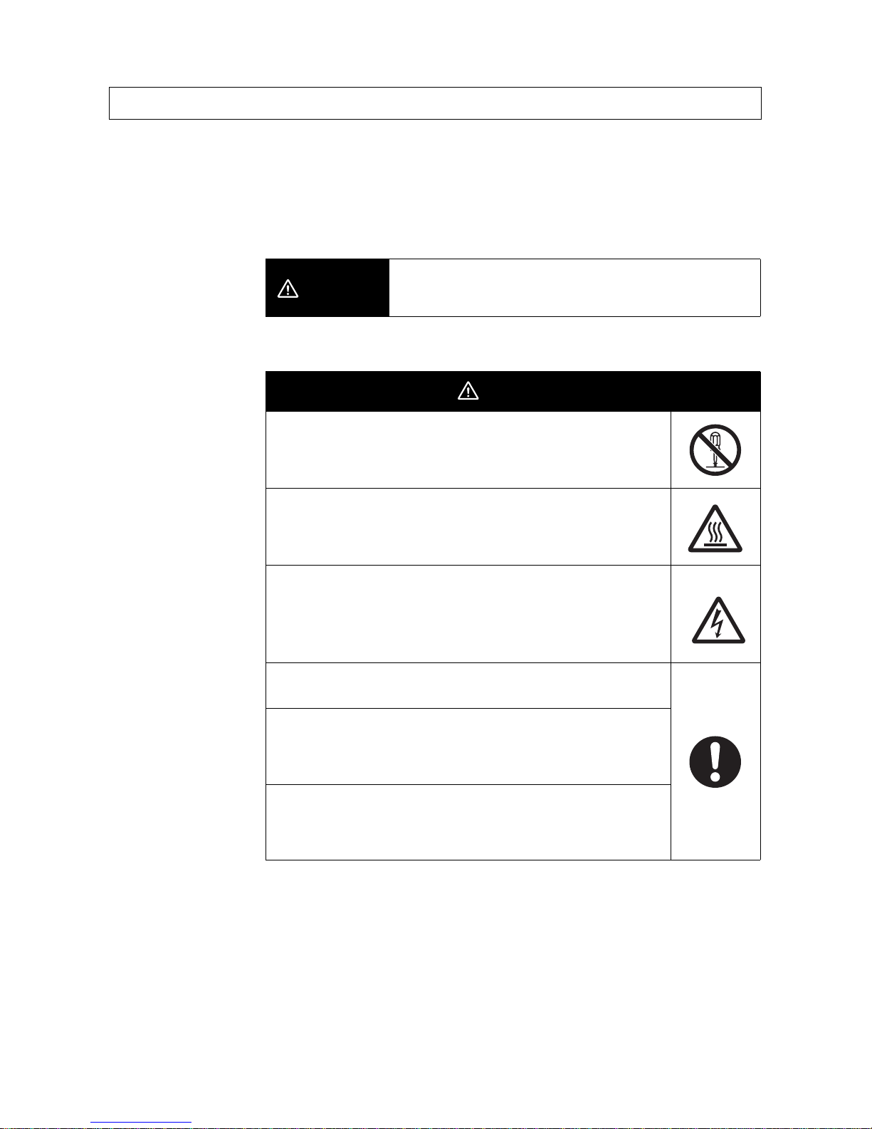
CAUTION
Indicates a potentially hazardous situation which, if not
avoided, may result in minor or moderate injury or in
property damage.
CAUTION
Minor electric shock, fire, or Product failure may occasionally
occur. Do not disassemble, modify, or repair the Product or touch
interior of the Product.
Minor burns may occasionally occur. Do not touch the Product
during power is being supplied or immediately after power is
turned OFF.
Minor injury may occasionally occur due to electrical shock. Do
not touch the terminals while power is being supplied. Also, be
sure to close the terminal cover after wiring the terminals.
Fire may occasionally occur. Tighten terminal screws to the
specified torque.
Minor electric shock, fire, or Product failure may occasionally
occur. Do not allow any pieces of metal or conductors or any
clippings or cuttings resulting from installation work to enter the
Product.
A maximum voltage of 370 V may be generated internally when
power is supplied.
This voltage will remain for 30 s even after the power supply has
been turned OFF.
Page 12
xii
The S8AS Smart Power Supply combines the highly reliable S8VS Switch Mode Power Supply with the S8M
Digital Multicircuit Protector into a single unit to reduce both wiring and space requirements. The built-in digital
circuit protector uses semiconductor relays to close and trip circuits, and does not contain any contact
switching mechanisms, as normal circuit protector s do.
Observe the following precautions when introducing the S8AS into or using the S8AS in any system.
■ Installation and Storage Environment
1. Store the Product at an ambient temperature of –25 to 65°C and relative humidity of 25% to 90%.
2. To maintain performance of the maintenance forecast monitor, make sure the following conditions are
satisfied for long-term storage.
• For storage exceeding three months, keep the Product at a temperature of –20°C to 30°C and a
humidity of 25% to 70%.
3. Internal parts may occasionally be deteriorated or damaged. Do not use the Product in conditions
exceeding the derating curve (in portion (1) of the derating curve on pagexiv).
4. Inter nal par ts may possibly be damaged. Do not use a current that exceeds the rated total output current.
If temporary peak currents occur repetitively, design the system so that the peak currents do not ex ceed
the rated total output current.
5. The surrounding air temperature to comply with UL508 and UL60950-1 is 25°C.
6. Use the Product where the relative humidity is 25% to 85%.
7. Do not use the Product where it would be subjected to direct sunlight.
8. Do not use the Product where it would be subjected to the possibility of penetration of liquid, foreign
substance, or corrosive ga s.
9. Do not use the Product where it would be subjected to shock or vibration. A device such as a contact
breaker may be a vibration source. Set the Product as far as possible from possible sources of shock or
vibration. Additionally, install a PFP-M End Plate on each end of the Product after mounting it to a DIN
Rail.
10. Use a DIN Rail made of steel. If an aluminum DIN Rail is used, vibration or shock may cause the
formation of metal dust due to abrasion of the aluminum.
11. Poor heat dissipation may deteriorate or damage internal parts. Do not loosen the screws on the side of
the Product.
12. If the Product is used in an area with excessive electronic noise, be sure to separate the Product as far as
possible from the noise sources.
13. Cutoff p erformance is guaranteed according to the a mbient operating temperature. Use the Product withi n
the derating range. Refer to the Derating Curve on pagexiv.
14. Poor heat dissipation resulting from improper installation conditions may occasionally deteriorate or
damage internal parts and also cause the maintenance forecast monitor function to not operate properly.
Do not use any mounting orientation other than a standard one.
15. Do not conne ct a battery or other backup power supply to the output of the Product.
16. To comply with UL standards, insert a fast-breaking, UL-approved fuse rated at 20 A into each input line.
17. Although some inverters have an output frequency of 50/60 Hz, they may cause internal temperatures to
rise, possibly resulting in burning, if they are connected as the power source for the S8AS. Do not use the
output from an inverter as the power source for the S8AS.
Precautions for Safe Use
Standard Mounting
Face-up Mounting
Page 13

xiii
■ Installation and Wiring
1. Minor electric shock during operation may occasionally occur. Always attach the cover or take other
precautions so that the terminals cannot be touched directly.
Also, connect the ground completely. The ground is a protective earth (PE) terminal specified in safety
standards. If the ground is not connected completely, electric shock or malfunction may occur.
2. Minor fire may possibly occur. Ensure that input and output terminals are wired correctly.
3. Heat generated by wiring materials may cause the temperature of internal parts to increase, which may
result in deterioration of or damage to the internal par ts. Select the wiring ma terials according to the
current that is being used.
4. Using the wiring materials, torque, and wire stripping length specified in 3-3 Power Supply and Input/
Output Wiring is recommended to prevent smoke or fire of the wire material due to an abnormal load.
5. It is conceivable that internal parts may be deteriorated or damaged. Do not repeatedly perform cutoff or
recovery operations more than necessary.
6. Do not push more than 100 N of force to the terminal block when tightening screws.
7. Be sure to tighten the lock screws on the sides of the connector after connecting any output connector.
When removing a connector, be sure the lock screws are completely loose before pulling on the
connector.
8. Be sure to remove the sheet covering the Product during installation before turning ON the power.
■ Output Voltage Adjustment
1. The output voltage adjuster (V.ADJ.) may possib l y become damaged. Do not a pply more than the requ ired
force.
2. Do not exceed the rated output capacity and rated total output current after adjusting the outp ut voltage.
■ Periodic Inspections
Under normal operating conditions, the Product will require several years or even more than ten years until the
maintenance forecast monitor function operates. When using the Product for an extended period of time, perform the following procedure periodically to confirm that the output for the maintenance forecast monitor function (LFE) is operating correctly.
a) Change to Run Mode.
b) Confirm that the (LFE) output is ON (electrical continuity between LFE and COM).
Note For details about terminal names, refer to 2-1 Component Names and Functions.
Page 14
xiv
• When the tripping alarm output operates, always remove the cause of the output first and then reset the
alarm.
• When cycling the input power supply, always remove any problems first and then turn ON the input power
supply.
■ Startup Time
When the input power is turned ON to the S8AS, a hardware check, software check, and initialization processing are performed before the branch outputs are turned ON. Approximately three seconds is required. When
using the S8AS with other control equipment, incorp orate the startup time of the S8AS in the overall system
design.
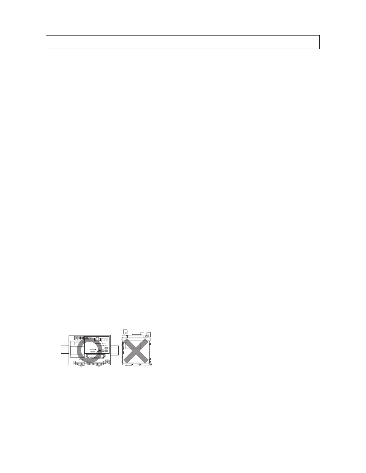
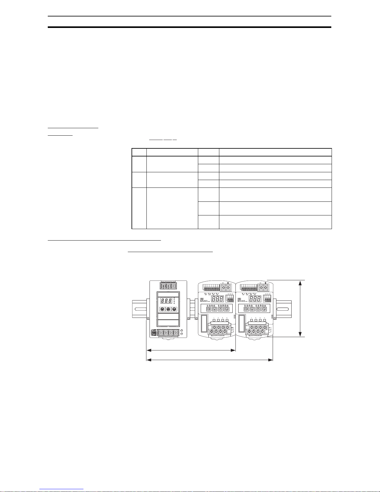
■ Installation
• Mounting Direction
Mount the S8AS to a DIN Rail using the standard mounting direction. Do not mount it in any other direction,
such as face up.
(Refer to 3-1 Installing the S8AS.)
• Mounting Space
The long-term reliability of the S8AS can be increased by installing it properly and sufficiently considering heat
dissipation.
Be sure to install the S8AS so that the air flow circulates around it, because the S8AS is designed to radiate
heat by means of natural air circulation.
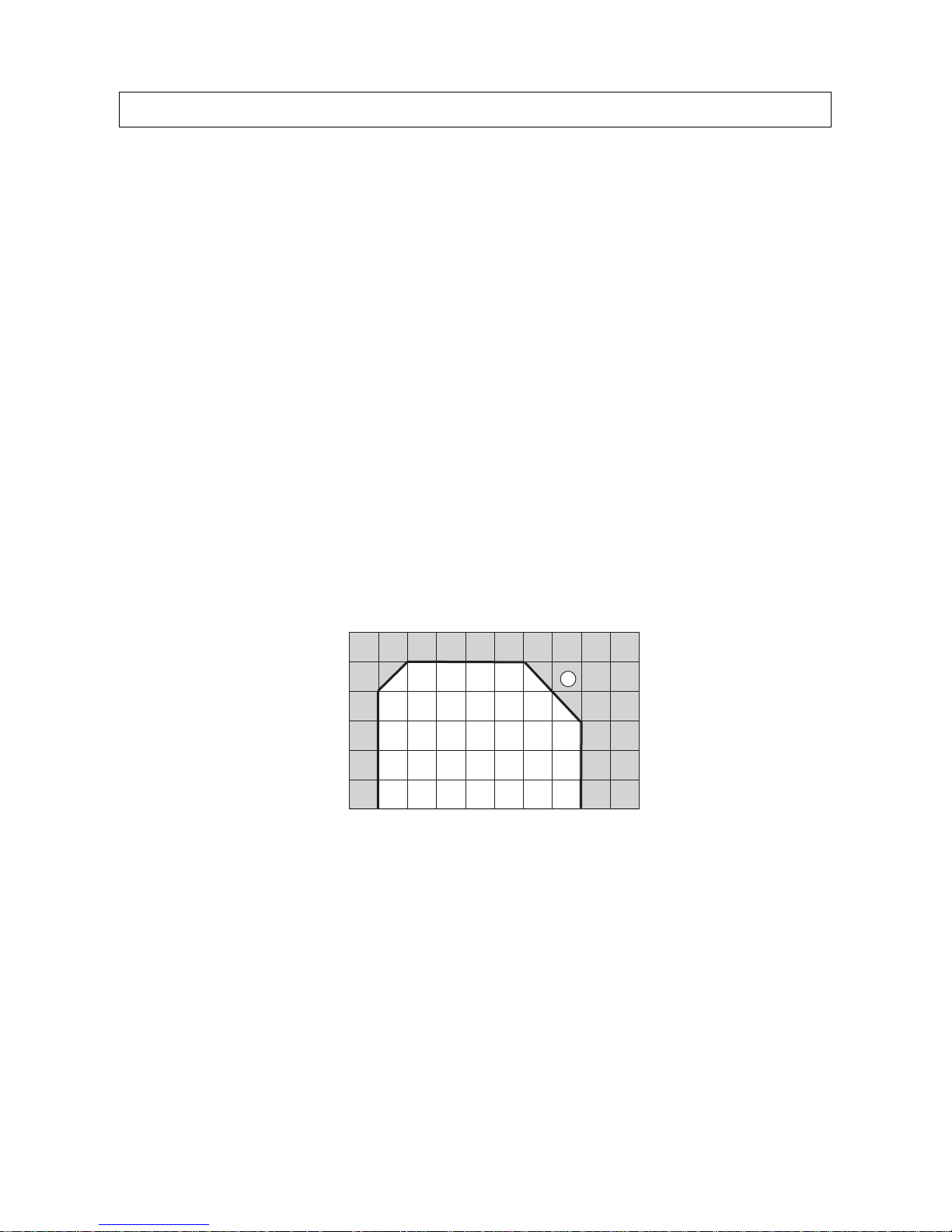
■ Derating Curve
The temperature range within which the S8AS can be used is restricted by the maximum current that normally
flows for the total output. This restriction is given as a derating curve.
Note
1. The ambient temperature is measured at a point 50 mm below the S8AS.
2. Use forced cooling if necessary to satisfy the derating curve.
3. For 480-W models , re duce the loa d to 80 % or le ss for long-term use at an input voltage of 95 VAC or less.
■ Abnormal Voltage Tripping
1. The S8AS has an abnormal voltage tripping function. All branch outputs will be cut off if the input voltage
exceeds 28.8 VDC. This function, however, does not protect loads and internal parts from high voltages in
all cases. Be sure the output voltage is within the rated range .
2. Outputs may be cut off by the abnormal voltage protection with loads that generate reverse peak electromotive force.
Precautions for Correct Use
Load rate (%)
Total output current
Ambient temperature (°C)
120
100
80
60
40
20
0
−20 −10 0 10 20 30 40 50 60 70 80
1
Page 15

xv
■ Abnormal Current Tripping
The S8AS has an abnormal current tripping function. A branch output will be cut off if its current exceeds a preset value. Also, all branch outputs will be cut off if their total peak output current exceeds a specified value.
Note
1. Continuing operation with o vercurrent may occa sionally result in deterior ation or destruction of internal ele-
ments.
2. Do not use the S8AS for applications in which load inrush current or overload will frequently occur.
Doing so may result in deterioration or damage to internal components.
■ Maintenance Forecast Monitor Function
The accuracy of the maintenance forecast monitor function will be reduced in applications where the AC input
turns ON and OFF frequently.
■ Tripping Performance
There are three methods that can be used to determine abnormal current trippings: Standard Detection,
Instantaneous Detection, and Extended Detection. (This is not possible for the S8AS-24006N/ 48008N.)
Refer to 2-4-2 Over-current Protection Functions for details of cutoff performance.
Note
1. When the tripping alarm output operates, always remove the cause of the output first and then reset the
alarm.
2. When using a load with a fixed-power operation, the S8AS may cause a cutoff when the power supp ly is
turned OFF.
3. Tolerance of current tripping alarm threshold is ±0.3 A.
4. Use Extended Detection only when using OMRON Remot e I/O Terminal with short-circuit detection.
■ Total Peak Output Current
The S8AS is designed to provide a temporary peak current to provide the overcurrent required to start load
devices.
The total peak output current for all branch outputs combined is given below.
If the total current exceeds any of these values, all branch outputs will be cut off according to the size of the
peak current or application time to ensure safety.
• 240-W Models
Input voltage range: 200 to 240 VAC
Peak current/Peak current pulse width: 17 A max. for 2 s max.
15 A max. for 5 s max.
13 A max. for 10 s max.
12 A max. for 20 s max.
If the total output peak current exceeds even one of these conditions, all branch outputs will be shut off to
ensure safety.
• 480-W Models
Input voltage range: 200 to 240 VAC
Peak current/Peak current pulse width: 27 A max. for 1 s max.
25 A max. for 2 s max.
22.5 A max. for 5 s max.
Note
1. If the input volta ge range is not within the v alues specified abo ve or the total output current e xceeds the max-
imum peak current value, internal operation will become unstable and the branch outputs may be cut off.
2. Maintain the total current f or normal oper ation after the load de vices ha v e started to within the rated r anges.
Page 16

xvi
3. Do not allow a peak current to flo w again for at least 60 seconds after a peak current has e xceeded the rated
current.
■ Startup Delay
The S8AS has a startup delay function that prevents cutoffs caused by inrush current at startup.
The startup delay disables the cutoff operation for 40 ms after the semiconductor relay turns ON.
To protect inter nal circuits, however, the relevant branch outputs will be cut off even during the startup delay
period if a current limit is exceeded within a specific time period.
Note The startup delay will not operate when a relay or other device is used fo r ON /OFF control on the output
side of the S8AS, so a cutoff operation may occasionally occur.
■ Dielectric Strength Test
The S8AS is designed to withstand 3,000 VAC for 1 minute between the AC input terminals collectively and
the branch output, I/O signal, or communications terminals collectively. When testing, set the cutoff current for
the withstand voltage test device to 20 mA.
Note
1. The S8AS may possib ly be damage d f rom th e imp ulse voltage if a testing device switch is used to abruptly
apply or cut off 3000 V A C. Increase the applied voltage grad ually using the voltage adjust ment on the testing
device.
2. When testing terminals together, always short the specified terminals so that the voltage is applied to all of
the terminals at the same time.
■ Insulation Resistance Test
When testing the insulation resistance, use a DC resistance meter at 500 VDC.
Note To prevent damage, always short branch output terminals (+/–), all I/O terminals, and communications
terminals before testing.
■ Output Voltage Adjustment
Default setting: Set as the rated voltage.
Adjustable range: Adjustable from –10% to +10% of the rated output voltage by using the V.ADJ. adjuster on
the front or the Power Supply. Turning the adjuster clockwise increases the output voltage, and turning it
counterclockwise decreases the output voltage.
Note
1. If the output voltage is set to less than 20 V (default setting), the undervoltage detection may be activated.
2. Do not exceed the rated output capacity and rated total output current after adjusting the output voltage.
3. The output voltage may increase beyond the allowable voltage range rated voltage +10% when the V.ADJ
adjuster is used. When adjusting the output voltage, check the output voltage of the power supply to make
sure that the load is not damaged.
■ No Output Voltage
The internal circuit’s overcurrent protection or overvoltage protection may operate. Alternatively, the latch
protection circuit may operate if there is a lightning surge or other large voltage applied to the input.
Contact your OMRON representative if there is still no output voltage after checking the following two points:
• Checking Overcurrent Protection
Check whether the load is in an overcurrent or short-circuited state. Remove the wires to the load before
checking.
• Checking Overvoltage Protection and Latching Protecti on
Turn the power supply OFF and leave it OFF for at least 3 minutes, then turn it ON again.
Page 17
xvii
■ Startup Time
At startup, the S8AS will check hardware and software before starting the operation of branch outputs.
A time of approximately 3 se conds is required for these self-diagnostic functions.
Take this time into account when designing the system.
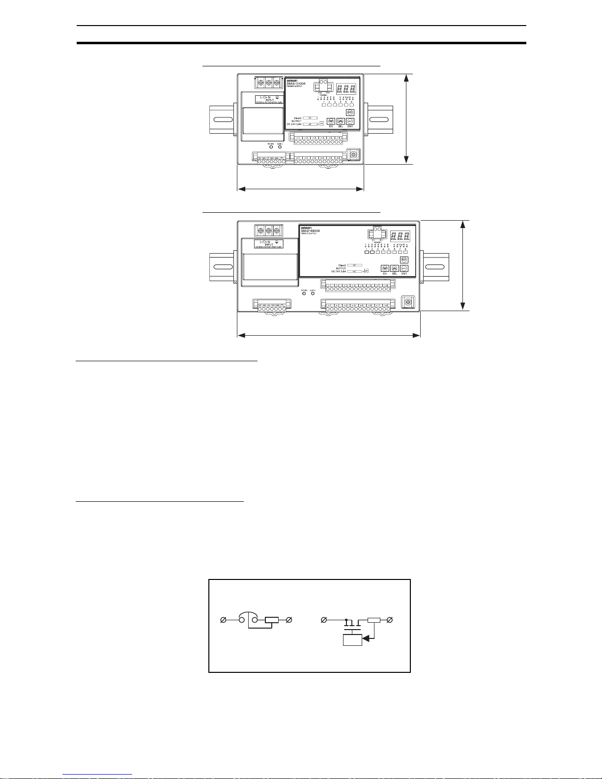
■ External Tripping Input
Wire the polarity of the external tripping input correctly. After completing wiring, confirm that operation is correct.
■ Tripping Alarm Output, Undervoltage Detection Output, Maintenance
Forecast Monitor Output, and Over-temperature Output
Photoswitch outputs: 30 VDC max., 50 mA max., residual voltage when ON: 2 V max., leakage current when
OFF: 0.1 mA max.
Wire all output signal circuits correctly. Internal current control circuits are not provided internally for output signals. Do not allow the output current to e xceed 50 mA. After completing wiring, confirm that the circuits oper ate
correctly.
■ Displaying the Output Voltage
The voltage detection function displays on the 7-segment display the voltage that is monitored at the internal
circuit after AC/DC conversion. The displayed voltage will be somewhat lower than the value at the output
terminals of the power source due to internal voltage drop. To accurately confirm the output voltage, measure
it at the branch output terminal.
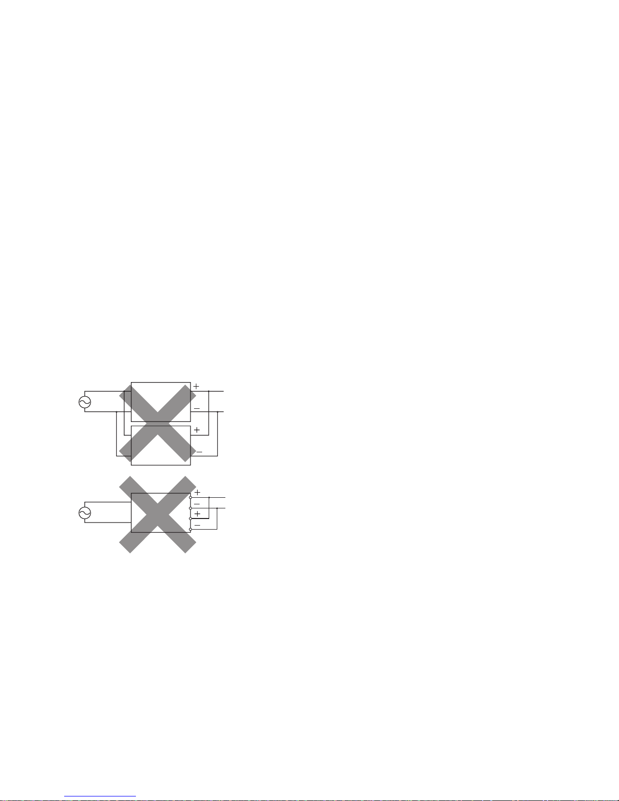
■ Prohibition of Parallel Connection
Do not connect branch outputs from the S8AS in parallel. Also, do not connect the branch outputs in parallel
with branch outputs of other S8AS Power Supplies.
■ Supplementary Information: Conformity to IEC and EN Safety Stan-
dards
Warning: The S8AS is a Class A product. In a residential, commercial, or light industrial environment, it may
cause radio interference. The S8AS is not intended to be installed in a residential environment. In a
commercial or light industrial environment with connection to a commercial power supply, the user may be
required to take adequate measures to reduce interference.
S8AS
S8AS
S8AS
Connections cannot be made in parallel
with other branch output circuits.
Page 18
xviii
■ Notation in this Manual
In this manual, the S8AS Smart Power Supply is referred to as the S8AS.
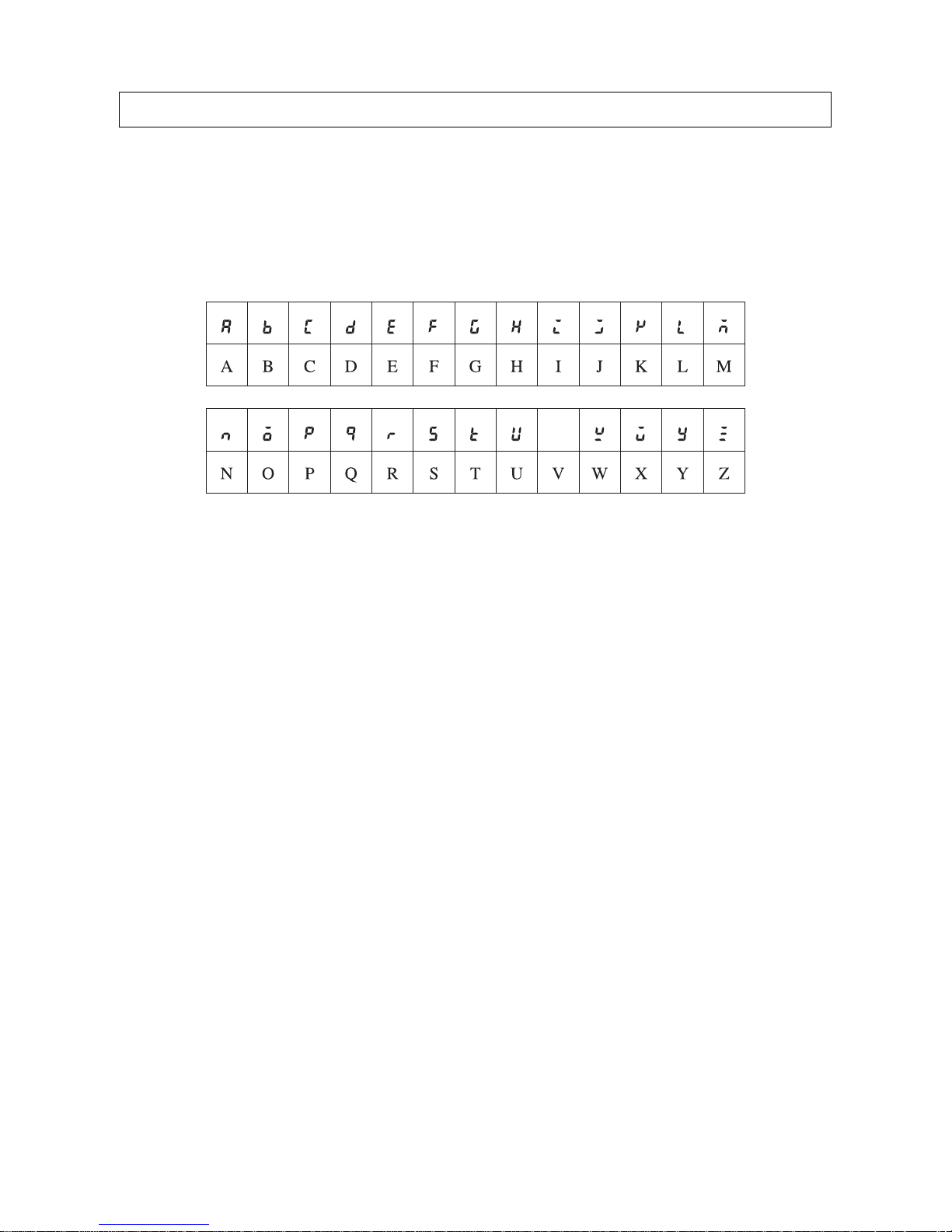
■ Notation of Setting Data
Setting data codes and contents are displayed in seven-segment display characters, as shown in the following
diagram.
Using this Manual
V
Page 19

1
SECTION 1
Features and Functions
This section describes the features and functions of the S8AS.
1-1 Overview of Features and Functions. . . . . . . . . . . . . . . . . . . . . . . . . . . . . . . . 2
1-2 S8AS Operating Modes . . . . . . . . . . . . . . . . . . . . . . . . . . . . . . . . . . . . . . . . . 7
1-3 Table of Basic Functions. . . . . . . . . . . . . . . . . . . . . . . . . . . . . . . . . . . . . . . . . 9
1-4 S8AS Operating Procedure. . . . . . . . . . . . . . . . . . . . . . . . . . . . . . . . . . . . . . . 13
Page 20
2
Overview of Features and Functions Section 1-1
1-1 Overview of Features and Functions
The S8AS Smart Power Supply is a 24-VDC power supply unit with an internal digital circuit protector that incorporates the highly reliable S8VS Switch
Mode Power Supply and the S8M Digital Multicircuit Protector in one unit.
The input power supply to the S8AS is 100 to 240 VAC at 50/60 Hz. Models
are available for 240 W with 6 branch outputs or for 480 W with 8 branch outputs, with and without communications. Models for which parameters cannot
be changed are also available.
The S8AS provides a stable 24-VDC power supply at an output current of 3.8
A maximum.
Model Number
Legend
S8AS Model Numbers
Reduced Space, Wiring, and Work
■ Combination of S8VS and S8M
The space required within the control panel and the amount of wiring have
been reduced by integr ating a Digit al Mu lticircuit Protector into a Switch Mode
Power Supply.
No. Item Code Meaning
1 Output capacity 240 240 W
480 480 W
2 Number of output
branches
06 6 branch outputs
08 8 branch outputs
3 Communications /
Additional functions
blank Changeable parameter settings with no com-
munications
N Unchangeable parameter settings with no
communications
R Changeable parameter settings with communi-
cations (RS-485)
S8AS-@@@@@@
1
2
3
115 mm
170 mm for models with 4 branch outputs
245 mm for models with 8 branch outputs
Page 21
3
Overview of Features and Functions Section 1-1
■ S8AS-24006@ (240 W, 6 Branch Outputs)
■ S8AS-48008@ (480 W, 8 Branch Outputs)
Power Supply and Branch Outputs
The power supply section incorporates the highly praised AC-DC conversion
circuit of the S8VS Switch Mode Power Supply in order to produce stable 24VDC power.
The branch output circuits consist of the protection circuits and tripping circuits of the S8M Digital Circuit Protector. They support various safety functions, such as overvoltage protection, overcurrent protection, and short-circuit
protection, as well as maintenance functions, such as monitoring using the
seven-segment display, error indications, and various alarm outputs .
Models that support communications can be monitored from a host computer
using RS-485 communications.
Branch Output Tripping Circuits
No-contact Switching The S8AS built-in circuit protectors differ from conventional mechanical con-
tact-type circuit protectors in that they use no-contact transistor relay switching. Without the contact life of mechanical cir cuit protectors, semiconductor
relays are able to provide a much longer lifetime. Digital processing also provides other benefits, such as being able to specify de ta ile d overcurrent detec tion conditions.
115 mm
160 mm for models
with 6 branch outputs
230 mm for models with 8 branch outputs
115 mm
Conventional contactstyle circuit protector
S8AS built-in circuit
protector
Overcurrent tripping
mechanism
Overcurrent
detection circuit
Page 22

4
Overview of Features and Functions Section 1-1
Tripping Current Can be
Set for Each Branch
Output
The abnormal tripping current value can be set for each branch output.
Setting range: 0.5 to 3.8 A (in 0.1 A increments).
Tolerance of current tripping threshold: ±0.3 A.
Abnormal Current
Detection and Tripping
Time
The abnormal current tripping characteristics can be set for each branch output. (This is not possible for the S8AS-24006N/48008N.)
There are three methods that can be used t o dete rmine abnormal current trippings. (This is not possible for the S8AS-24006N/48008N.)
■ Standard Detection
When the current exceeds the set value, the branch output is cut off within
100 ms.
■ Instantaneous Detection
When the current exceeds the set value, the branch output is cut off within
20 ms.
■ Extended Detection
When the current exceeds the set value, the branch output is cut off within
1,000 ms.
Error Indication and Alarm
Output for Abnormal
Current Tripping
The following will occur when an abnormal current is detected and the branch
output is cut off:
• The branch output status indicator will light red.
• The seven-segment display will show the error code A11 and the abnormal current value alternately.
• The external output terminal for tripping alarms (TRP) will tur n ON. (The
photoswitch output will turn OFF.)
Always remove the cause of the abnormal current before resetting the alarm.
Tripping for Total Peak
Output Current
When the total branch output current exceeds the set value for a specified
amount of time, all branch outputs will be cut off.
• All branch output status indicators will light red.
• The seven-segment display will flash the error code A12.
• The external output terminal for tripping alarms (TRP) will tur n ON. (The
photoswitch output will turn OFF.)
Abnormal Voltage
Tripping
If the output voltage exceeds 28.8 VDC, all branch outputs will be cut off in
order to protect load devices.
The following will happen when this occurs:
• The seven-segment display will show the error code A10 and the abnormal voltage alternately.
• The external output terminal for tripping alarms (TRP) will tur n ON. (The
photoswitch output will turn OFF.)
Internal Temperature
Monitor
The S8AS has an built-in temperature sensor that constantly measures the
internal temperature. The temperature can be read from the seven-segment
display. The temperature display range is −20 t o 10 0°C. The temperature sensor has one external output (TMP), which can be used to control cooling
equipment for the control panel.
The temperature output setting range is 25 to 90°C.
• The seven-segment displa y wi ll sho w the err or code A30 and tem per atur e
(°C) alternately.
Page 23
5
Overview of Features and Functions Section 1-1
• The external output terminal for over-temperature (TMP) will turn ON.
(The photoswitch output will turn OFF.)
Maintenance Forecast
Monitor Function
This function calculates the condition of the electrolytic capacitor based o n the
power-ON time and internal temperature of the Power Supply to forecast
when the Power Supply needs to be replaced. The monitor value can be set to
between 0.0 and 5.0 years (approximate) in increments of 0.5 years.
The following occurs when the estimated replacement time reaches the set
value:
• The seven-segment display will show the error code A23 and the replacement time (years) alternately.
• The external output terminal for the maintenance forecast monitor (LFE)
will turn ON. (The photoswitch output will turn OFF.)
Safety Functions If an abnor mal voltage or current is detected, the semiconductor relay will cut
off the branch output. In the unlikely event that the semiconductor relay cannot cut off an abnormal current or short-circuit current, the short-circuit protection fuse will cut the circuit to protect the system. If the branch output is cut off
by the fuse, an error indication will not be shown on the seven-segment display and the alarm output (TRP) will not operate.
The overcurrent protection fuse or over-temperature fuse cannot be replaced.
If a fuse burns out, use a different branch output or replace the S8AS.
External Outputs The S8AS has 4 external outputs: the Tripping Alarm Output (TRP), Under-
voltage Detection Output (LOW), Maintenance Forecast Monitor Output
(LFE), and Over-temperature Output (TMP).
Output Output condition Restoration condition
Tripping Alarm
Output (TRP)
• Abnormal voltage tripping
If the output voltage exceeds
28.8 V , all branch outputs are
cut off.
• Abnormal current tripping
If a current exceeding the set
value is detected, the corresponding branch output is
cut off.
The output status is retained
when power is interrupted but
can reset with the reset operation.
Test Mode only
When even one branch output
is disconnected.
Restore by connecting all
branch outputs, or by switching to any mode other than
Test Mode.
Undervoltage Detection Output (LOW)
Output when the 24 VDC output falls below the undervoltage detection threshold.
This output can be reset with
the reset operation. If the
alarm is cleared when the
power is turned ON, the output will be reset.
Over-temperature
Output (TMP)
Output when a temperature
exceeding the threshold is
detected.
The output is reset automatically when the temperature
falls to 3°C below the overtemperature output threshold.
Maintenance Forecast Monitor Output
(LFE)
•Output when the estimated
replacement time falls below
the set value.
• Output when the replacement time can no longer be
calculated due to rise in temperature of the power supply
section.
•Prepare to replace the
Power Supply.
•Take measures to lower the
internal temperature.
Page 24

6
Overview of Features and Functions Section 1-1
Tripping Functions Using External Signals
Branch outputs can be forcibly cut off by turning ON the External Tripping
Input (TRG).
• Tripping using the External Tripping Input can be enabled or disabled
independently for each branch output. Refer to Tripping Input Trigger Set-
ting: TRG (Trigger) on page 68.
• The Exter nal Tripping Input directly cuts off a b ranch output's DC circuit,
so it acts eve n faster than cutting off the output by turning OFF the normal
AC power supp ly.
• When a shutdown sequence has been set, this function can be used to
set a time lag for the branch output cutoff. (For details, refer to 2-6 Shut-
down Sequence Function.)
• The tripping input type can be set. (Refer to 2-7 External Tripping Input
Function)
• EGE: Output cut off when the tripping input changes from OFF to ON.
• LVL: Output cut off when the tripping input changes from OFF to ON
and connected when tripping input changes from ON to OFF.
Additional Functions
Startup Sequence
Function
A delay can be set for t he connection of the br anch outputs . When y ou w ant to
apply a startup delay to the branch output, it is not necessary to construct an
external sequence circuit. The inrush current can be suppressed by applying
a delay and the Power Supply Unit's load can be reduced. (For details, ref er to
2-5 Startup Sequence Function.)
Shutdown Sequence
Function
The branch outputs' cutoff can be delayed. When you want to apply a shutdown delay to the branch output, it is not necessary to construct an external
sequence circuit. (For details, refer to 2-6 Shutdown Sequence Function.)
Protecting Parameter
Settings (Protection Level
Settings)
The Protection Level can be set to restrict access to the parameters. Three
levels, levels 0, 1, and 2, are available. This function can be used to prevent
parameters from being changed or deleted inadvertently.
The default setting is protection level 1. (For details, refer to 4-3 Changing the
Protection Level.)
Note The read/wr ite access for models that do not support parameter
changes (S8AS-24006N/48008N) cannot be changed regardless
of the protection level.
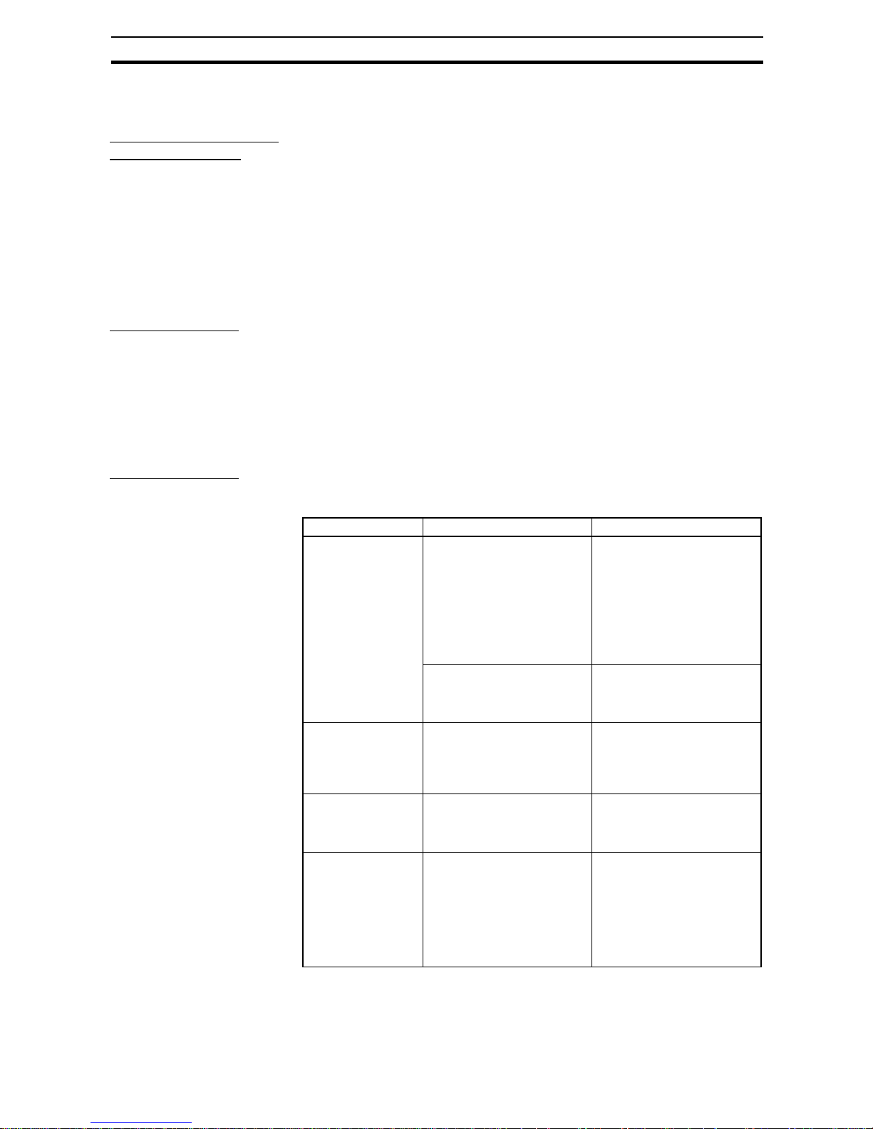
Protection level Restrictions
0 There are no restrictions on reading and changing the parameter
settings.
1 Permits only reading and changing of the output voltage, current,
internal temperature, and maintenance forecast monitor parameters.
2 Permits only reading of the output voltage, current, internal tem-
perature, and maintenance forecast monitor parameters.
Page 25
7
S8AS Operating Modes Section 1-2
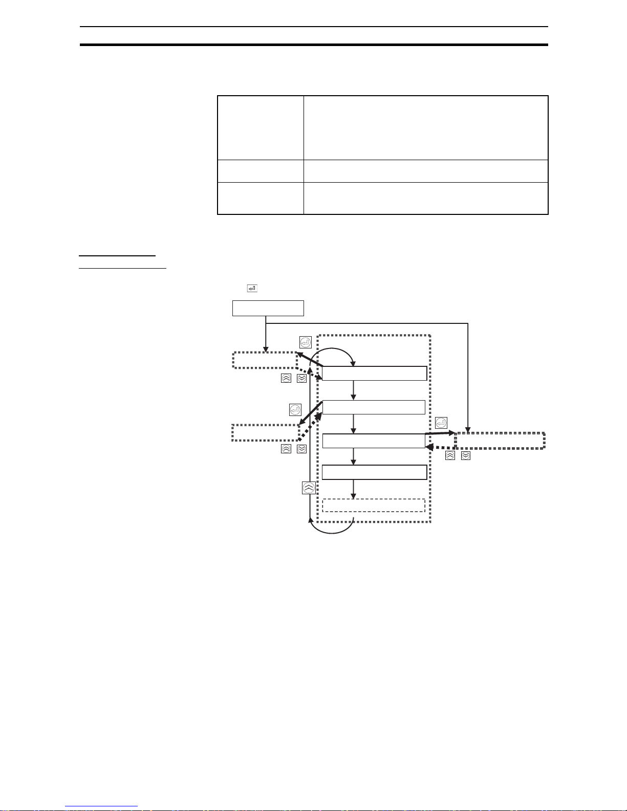
1-2 S8AS Operating Modes
The S8AS has 3 operating modes: Run Mode, Setting Mode, and Test Mode.
Note Test Mode can be entered only in protection level 0 or 1.
Changing the
Operating Mode
To change the operating mode, press the Up (SEL) (U) and Down (CH) (D)
Keys simultaneously for 3 s. The Mode Selection Menu will be displayed. Use
the Up (SEL) Key to select the desired operating mode and then press the
Enter ( ) Key.
Note (1) The Protection Level function can restrict parameter rea d/write access to
one of three lev els. F or details, ref er to 4-3 Changing the Protection Level.
(2) The Initialize Parameters function restores all of the S8AS's parameter
settings to their default values. For details on default values, refer to 4-1
Parameter Table.
(3) T est Mode can be entered only in protection level 0 or 1.
(4) The Setting Mode, Protection Level, or Parameter Initialization options
cannot be accessed with models such as S8AS-24006N/48008N that d o
not permit changes in parameter settings.
Run Mode The output voltage, output current, internal temperature, and
run time are monitored while supplying 24 VDC to the branch
outputs. The monitored values can be displayed on the sevensegment display.
The S8AS automatically starts in Run Mode when the S8AS is
used for the first time.
Setting Mode This mode is used to set parameters. Branch output connec-
tions are the same as in Run Mode.
Test Mode
(See note.)
This mode is used to test operation. The factory default setting
for all outputs is ON, so any branch outputs that are not being
used must be turned OFF in Test Mode.
+
+
Power ON
• When started for the
first time
• S8AS was not in Test
Mode when power
went OFF.
Run Mode
Setting Mode
Press for 3 s.
Press for 3 s.
Press for 3 s.
Mode Selection Menu
Select Run Mode run (RUN)
Select Setting Mode set (SET)
Select T est Mode tst (TST)
S8AS was in
Test Mode
when power
went OFF.
Select Protection Level prt (PRT)
Initialize Parameters ini (INI)
Test Mode (See note 3.)
The Initialize Parameters
command is displayed in
protection level 0 only.
(See
note 4.)
(See
note 4.)
(See
note 4.)
+
Page 26

8
S8AS Operating Modes Section 1-2
Turning the Power ON for
the First Time
• When a newly purchased S8AS is turned ON for the first time, it will enter
Run Mode with all the branch outputs turned ON. To change parameter
settings, return to the Mode Selection Menu and switch to Setting Mode.
Refer to SECTION 4 Par ameter Settings for details on setting parameters.
• T o start trial operation or to set branch output con nections after setting the
parameters, return to the Mode Se lection Menu and switch to Test Mode.
Refer to SECTION 5 Trial Operation to Actual Operation for details on the
operations in Test Mode.
• When changing to Run Mode after completing trial operation, return to the
Mode Selection Menu and switch to Run Mode. If the power is turned
OFF while the S8AS is in Test Mode, the S8AS will enter T est Mode again
the next time that the power is turned ON. All branch outputs will retain
the connection status they had before the power was turned OFF.
Normal Power-ON
Procedure
If the S8AS has been turned ON already, it will enter Run Mode or Test Mode
the next time that power is turned ON. If the S8AS was in T est Mode when the
power went OFF, it will start in Test Mode. If it was in a mode other than Test
Mode when the power went OFF, it will start in Run Mode.
In addition to selecting the operating mode, the Mode Selection Menu can be
used to select the protection level and initialize the parameters (see note 2).
(These options cannot be selected when using the S8AS-24006N/48008N.)
The Initialize Parameters function restores all of the S8AS's parameter settings to their default values. For details on default values, refer to Turning t he
Power ON for the First Time.
Automatic Operation
after Power ON
When the rated voltage (100 to 240 VAC, 50/60 Hz) is applied to the AC input
terminal block, the S8AS performs self-diagnostics (hardware and software
checks) for approximately 3 seconds. (“AS” will flash on the seven-segment
display during the self-diagnostic process.) If no errors are detected, the
S8AS will immediately start connecting the branch outputs.
Branch outputs will not be connected if they were not set to ON in Test Mode.
Furthermore, if the startup sequence function (refer to 2-5 Startup Sequence
Function) has been set, the branch outputs will be connected according to
their corresponding settings.
Operation in Run
Mode
In Run Mode, the S8AS continuously measures the output voltage, branch
output circuit currents, and internal temperature, and compares these values
to the set values (both user-set par ameters and system set values).
Monitor Operation The monitored output voltage, branch output currents, branch output peak
current, total current, internal temperature, and replacement time can be read
on the S8AS's seven-segment display. The displayed value can be switched
with the Up (SEL) Key (U) and Down (CH) Key (D).
Tripping Operation If the voltage or current is abnormal, the branch output will be cut off to protect
the circuit.
■ Abnormal Voltage Tripping
All branch outputs will be cut off if the output voltage exceeds 28.8 VDC in
order to protect the load devices.
■ Abnormal Current Tripping
A branch output will be cut off if the tripping current threshold (see note) or an
abnormal current is detected using the specified current detection method
(see note). (The tripping current threshold and current detection method cannot be changed for the S8AS-24006N/48008N.)
Page 27
9
Table of Basic Functions Section 1-3
An error code will be displayed, and the tripping alarm output will operate
when a branch output is cut off.
Other Status Monitoring The internal temperature and replacement time status are monitored and
error processing is performed if an error is detected.
Operation in Setting
Mode
Setting Mode can be used to set the v arious paramet ers. The S8AS is in operating status when it is in Setting Mode. Branch outputs are connected in Setting Mode in the same way as in Run Mode. When an error is detected,
branch outputs will be cut off and alarms will be output, just as they are in Run
Mode.
Note If an error occurs in Setting Mode, the error code is not displayed.
Operation in Test
Mode
In Test Mode, each branch output can be set to ON or OFF (connected or d isconnected).
The factory default setting f o r all outputs is ON, so an y branch outp uts that are
not being used must be turned OFF in Test Mode.
In Test Mode, the operation of each branch circuit can be verified as well as
the operation of the startup sequence and shutdown sequence.
Note (a) If the power is tur ned OFF while the S8AS is in Test Mode, the
S8AS will enter Test Mode again the next time that the power is
turned ON.
(b) When an error occurs in Test Mode, branch outputs will be cut off
and external signals will be output, just as they are in Run Mode.
The error code will not be displayed.
(c) Refer to 7-3 Clearing Errors for details on clearing errors.
Note (1) When the S8AS is shipped from the factory, all bra nch outpu ts ar e se t to
ON (connected) and the S8AS will enter Run Mode when the power is
turned ON. After setting the parameters that require changing, switch to
Test Mode, set the switching status of the required branch outputs, and
then switch to Run Mode.
(2) If a branch output is OFF (disconnected) when the mode is changed from
Test Mode to Run Mode, it will not be connected (ON) in Run Mode.
(3) If the power is turned OFF while the S8AS is in Test Mode, the S8AS will
start in Test Mode the next time that the power is turned ON, but all
branch outputs will be OFF.
1-3 Table of Basic Functions
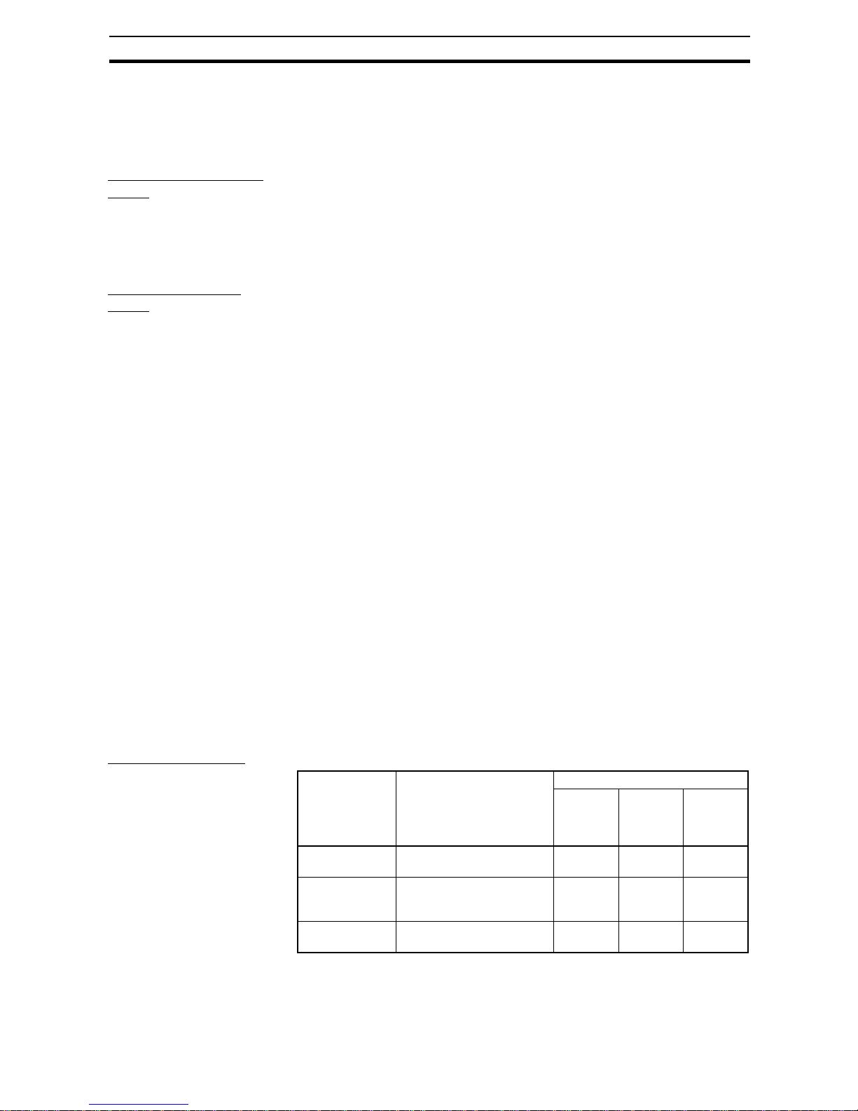
Monitor Functions
Monitored
parameter
Details Indications
Seven-
segment
display
Branch
output
number
indicators
Unit
indicators
Output voltage Displays the output voltage. 16.3 to
30.0
Not lit V
Tota l current Displays the sum of all the
branch output currents.
0.0 to 40.0 All
branches
lit
A
Branch output
current
Displays individual branch
output currents.
0.0 to 20.0 Lit A
Page 28

10
Table of Basic Functions Section 1-3
Setting Functions Refer to SECTION 4 Parameter Settings for details on parameter settings.
(These parameters cannot be changed for the S8AS-24006N/48008N.)
Branch output
peak current
Displays individual branch
output peak currents.
0.0 to 20.0 Lit A
(flashing)
Replacement
time
Displays the estimated number of years left until the
S8AS needs to be replaced.
(Setting: 0.0 to 5.0 years, in
0.5-year increments.)
FUL, HLF
0.0 to 5.0
Not lit Yrs
Internal temperature
Displays the S8AS's internal temperature.
−20 to 100 Not lit °C
Monitored
parameter
Details Indications
Seven-
segment
display
Branch
output
number
indicators
Unit
indicators
Data name Detail Setting
range
Undervoltage
detection threshold
The undervoltage detection output (LOW) is output
when the output voltage of the S8AS falls below this
detection threshold. The detection threshold can be
set in 0.1-V increments. Branch outputs will not be
cut off.
18.0 to
26.4 V
Abnormal current
tripping threshold
The current tripping threshold can be set for each
branch output in 0.1-A increments.
0.5 to
3.8 A
Abnormal current
tripping type
The tripping type can be set for each branch output.
USU: Standard (tripping within 100 ms)
INS: Instantaneous (tripping within 20 ms)
LNG: Extended (tripping within 1,000 ms)
USU/INS/
LNG
Maintenance
forecast monitor
function
Set the expected number of years until the S8AS
needs to be replaced. When the estimated value falls
below the set value, the maintenance forecast monitor output (LFE) will turn ON. (The photoswitch output
will turn OFF.)
0.0 to
5.0 yr
Over-temperature threshold
An excessive temperature rise inside the S8AS will
be detected and the over-temperature output (TMP)
will turn ON. (The photoswitch output will turn OFF.)
This output can be used to control cooling equipment
to reduce the temperature in the control panel.
25 to 90°C
Startup
sequence
The connection of branch outputs may be initiated by
communications or when the power is turned ON,
and a time delay can be set for the connection
sequence. Connecting the branch outputs in
sequence instead of simultaneously can reduce the
inrush current and reduce the load on the Power Supply.
0.0 to
99.9 s
Shutdown
sequence
Branch outputs can be disconnected in sequence initiated by communications or an external tripping input
(TRP), and a time delay can be set for the sequence.
0.0 to
99.9 s
Tripping trigger
input
The external tripping input function (TRG) can be
enabled (ON) or disabled (OFF) for each branch output.
OFF, ON
Tripping trigger
type
The tripping trigger type can be set for all branches
that have the tripping input function enabled.
EGE, LVL
Page 29
11
Table of Basic Functions Section 1-3
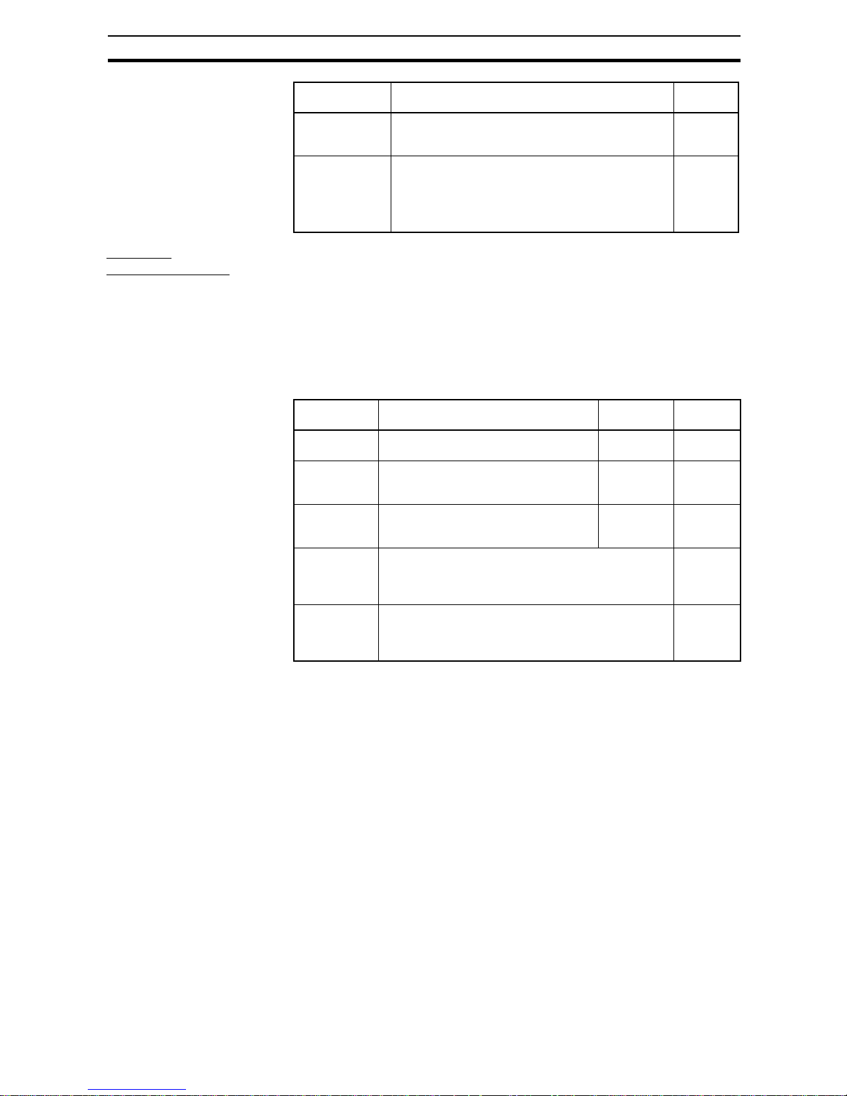
Tripping/
Alarm Functions
There are three ways for the S8AS's tripping function to operate:
• Tripping by user-set parameters
• Tripping by the S8AS's system monitor
• Tripping by external operation
The external signal outputs include the Tripping Alarm Output (TRP), Undervoltage Detection Output (LOW), Maintenance Forecast Monitor Output
(LFE), and Over-temperature Output (TMP).
Tripping Functions
Note (1) The tripping function operates within 100 ms when the S8AS is set to
standard detection, within 20 ms when it is set to instantaneous detection, and within 1,000 ms when it is set to extended detection.
(2) The TRG signal applies only to the branch outputs for which the e xte rnal
tripping input is enabled. For details, refer to 2-7 External Tripping Input
Function.
Protection level The Protection Level function can restrict parameter
read/write access by setting one of three levels. The
default protection level is level 1.
0 to 2
Reset operation The tripping alarm output and alarm output can be
cleared after removing the cause of the alarm by the
following two methods.
•KEY: RST Key only.
• ALL: RST Key or turning power OFF and ON again.
KEY, ALL
Data name Detail Setting
range
Setting Operating range Parameter
settings
Outputs
cut off
Abnormal voltage tripping
Output cut off for voltage over 28.8 VDC. None All branch
outputs
Short-circuit
current
tripping
Output cut off at 16 A for 20 ms max.
Output cut off at 11 A for 60 ms max.
None Individual
branch output
Abnormal total
current tripping
Output cut off when the sum of all branch
output currents exceeds the set value for
a specific length of time.
None All branch
outputs
Abnormal
current
tripping
(See note 1.)
0.5 to 3.8 A (in 0.1-A increments)
Select from standard, instantaneous, and extended
detection methods.
Individual
branch output
External tripping input
•External input signal (TRG) ON
•Tripping by communications.
Specified
output
(See note
2.)
Page 30

12
Table of Basic Functions Section 1-3
Alarm Output and Error
Display Functions
Note (1) In this manual, the lifetime of the Unit is expressed in years.
(2) If the overheating alarm stays on for more than 3 hours, it can no longer
be cleared.
Symbol Output
name
Operation Error code
displayed
TRP Tripping
alarm output
Abnormal Voltage Tripping Operati on
When the output voltage exceeds 28.8 VDC,
all branch outputs are cut off and the TRP
output is turned ON. (The photoswitch output
is turned OFF.)
A10
Abnormal Current Tripping Operation
When the branch output current exceeds the
set value, the branch output is cut off and the
TRP output is turned ON. (The photoswitch
output is turned OFF.)
A11/Current
(alternating)
Volt-amperage (VA) Tripping Operation
When the voltage times the current (VA)
exceeds the set value for a specified amount
of time, the branch output is cut off and the
TRP output is turned ON. (The photoswitch
output is turned OFF.)
A11/Current
(alternating)
Abnormal Total Current Tripping Operation
When the total output current exceeds the set
value, all branch outputs are cut off and the
TRP output is turned ON. (The photoswitch
output is turned OFF.)
A12
Indicates that there are branch outputs that
are not connected. This error is not output in
any mode other than Test Mode.
When there is a disconnected branch output
in Test Mode, the TRP output is turned ON.
(The photoswitch output is turned OFF.)
---
LOW Undervolt-
age detection output
Setting range: 18.0 to 26.4 VDC (0.1-V increments)
When the output voltage falls below the set
value, the LOW output is turned ON. (The
photoswitch output is turned OFF.)
A21/V oltage
(alternating)
LFE Mainte-
nance forecast monitor
output
Setting range: 0.0 to 5.0 years (0.5-yr increments) (See note 1.)
When the internally calculated replacement
time falls below the set value, the LFE output
is turned ON. (The photoswitch output is
turned OFF.)
A23/
Replacement time
(alternating)
Overheating
alarm (See
note 2.)
LFE output is turned ON (the photoswitch output is turned OFF) when the replacement
time cannot be calculated correctly due to rise
in internal temperature.
A23/HOT
(alternating)
TMP Over-tem-
perature
output
Setting range: 25 to 90°C (1°C increments)
When the temperature falls below the set
value minus 3°C, the TMP output and the
error code shown on the seven-segment display will be automatically cleared.
A30/Temperature (alternating)
Page 31

13
S8AS Operating Procedure Section 1-4
1-4 S8AS Operating Procedure
Using the S8AS
Typical Startup Proc edure
Using the S8AS's Keys
Summary of Application Objectives and Settings
Preparation
Installation and wiring
Power ON
Set parameters
Trial run in Test Mode
Verify operation
Actual operation
See Section 3 Installation and Wiring.
See Section 4 Initial Settings.
(S8AS-24006N/48008N parameters
cannot be changed.)
See Section 5 Trial Run.
Branch outputs that will not be used can be
set to OFF (disconnected.)
Verify proper operation while monitoring status in Run Mode.
Desired objective/
usage
Settings Details
Use as a circuit
breaker with overcurrent tripping.
In Setting Mode, set the abnormal current tripping threshold (C-V) for the branch output being
used and set the abnormal current tripping
detection setting (C-T) to standard detection
(USU).
p. 30,
p. 62
Use as a circuit
breaker for short-circuit current protection.
In Setting Mode, set the abnormal current tripping threshold (C-V) for the branch output being
used and set the abnormal current tripping
detection setting (C-T) to instantaneous detection (INS).
Detect a drop in
power supply voltage.
In Setting Mode, set the undervoltage detection
threshold (V-U). Take the alarm signal from the
Undervoltage Detection Output (LOW) terminal.
When an undervoltage is detected, the sevensegment display will show error code A21 and
the LOW output photoswitch output will go OFF.
p. 29,
p. 50
p. 63
Apply a separate
time lag when connecting each branch
output.
In Setting Mode, set the startup sequence
(UPS).
p. 37,
p. 66
Apply a separate
time lag when cutting
off each branch output.
In Setting Mode, set the shutdown sequence
(DWS) and enable the External Trip ping Input
(TRG).
p. 38,
p. 67
Use the S8AS
replacement time for
better maintenance.
The seven-segment display and the LFE terminal signal output can be used to check the estimated replacement time using the maintenance
forecast monitor function.
p. 34,
p. 64
Page 32

14
S8AS Operating Procedure Section 1-4
Monitor temperature
rise in control panel
and prevent overheating.
In Setting Mode, set the over-temperature output
threshold (TMP). Take the signal from the Overtemperature Output (TMP) terminal and use that
signal to operate a fan or air conditioner.
p. 35,
p. 65
p. 50
Restrict read/write
access of parameters to prevent mistaken operations.
Select the protection level setting (PRT) from the
Mode Selection Menu and set the desired protection level.
p. 54,
p. 59
Desired objective/
usage
Settings Details
Page 33

15
SECTION 2
Specifications and Functions
This section provides the specifications of the S8AS and describes special S8AS functions.
2-1 Component Names and Functions . . . . . . . . . . . . . . . . . . . . . . . . . . . . . . . . . 16
2-2 Internal Configuration. . . . . . . . . . . . . . . . . . . . . . . . . . . . . . . . . . . . . . . . . . . 20
2-3 Specifications . . . . . . . . . . . . . . . . . . . . . . . . . . . . . . . . . . . . . . . . . . . . . . . . . 22
2-4 Basic Function Details . . . . . . . . . . . . . . . . . . . . . . . . . . . . . . . . . . . . . . . . . . 29
2-4-1 Voltage Monitoring and Protection Functions . . . . . . . . . . . . . . . . . 29
2-4-2 Over-current Protection Functions . . . . . . . . . . . . . . . . . . . . . . . . . . 30
2-4-3 Maintenance Forecast Monitor Function . . . . . . . . . . . . . . . . . . . . . 34
2-4-4 Over-temperature Output . . . . . . . . . . . . . . . . . . . . . . . . . . . . . . . . . 35
2-5 Startup Sequence Function . . . . . . . . . . . . . . . . . . . . . . . . . . . . . . . . . . . . . . . 37
2-6 Shutdown Sequence Function. . . . . . . . . . . . . . . . . . . . . . . . . . . . . . . . . . . . . 38
2-7 External Tripping Input Function . . . . . . . . . . . . . . . . . . . . . . . . . . . . . . . . . . 39
Page 34
16
Component Names and Functions Section 2-1
2-1 Component Names and Functions
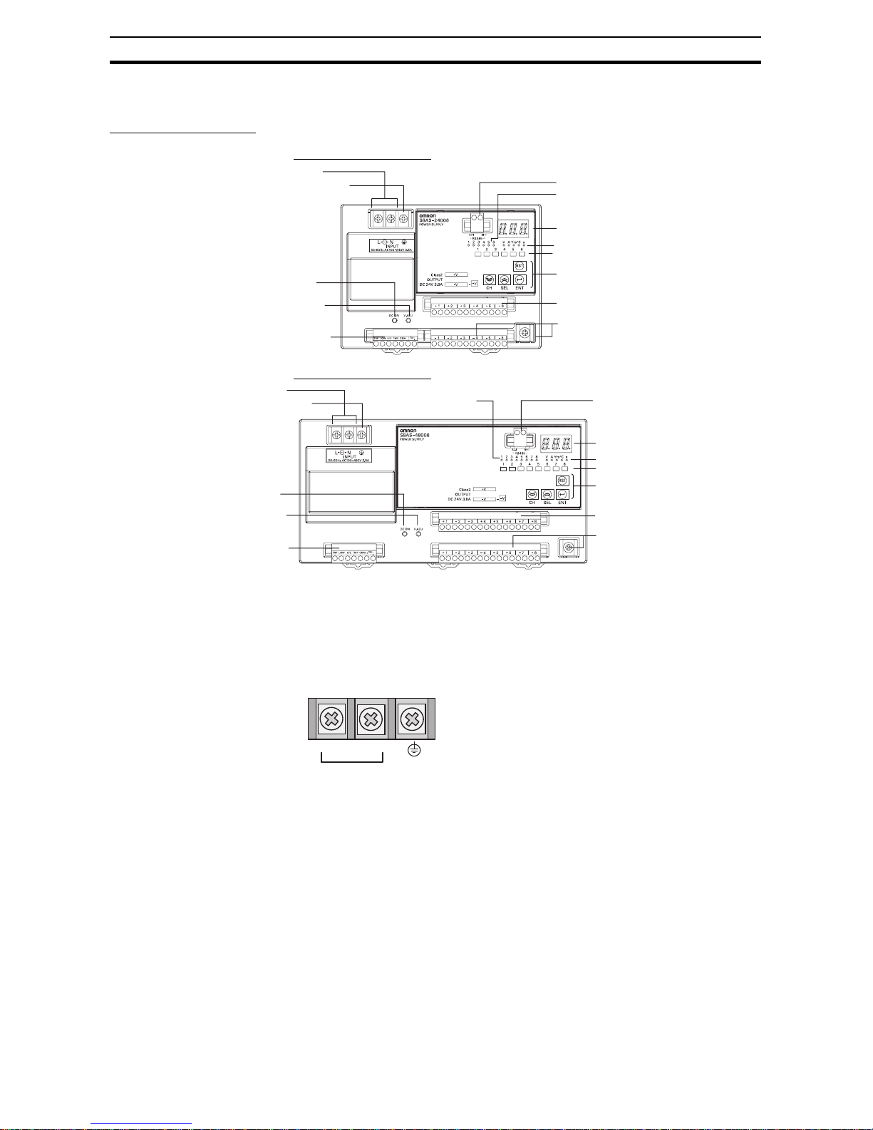
Component Names
■ 240-W Output Models
■ 480-W Output Models
(1) AC Input Terminals (L and N) and (2) Protective Earth (PE) Terminal
Connect the input power supply (100 to 240 VAC, 50/60 Hz) (commercial
power) to the Power Supply.
Do not connect an inverter output as the power supply.
Make sure that the protective earth (PE) terminal is connected to ground to
prevent electric shock or malfunction.
(3) Positive (+) and (4) Negative (−) Branch Output Terminals
Connect to each branch output. Positive and negative branch outputs are connected to separate terminal blocks with two positive and two negative terminals for each branch output.
1. AC input terminals
2. Protective earth (PE) terminal
3. Branch output terminals (+)
4. Branch output terminals (−)
6. Output indicator (DC ON)
7. Output voltage adjuster (V.ADJ)
8. Seven-segment display
5. I/O signal terminals
13. Communications terminal
s
9. Branch output indicators
10. Unit indicators
11. Status indicators
12. Operation keys
1. AC input terminals
2. Protective earth (PE) terminal
6. Output indicator (DC ON)
7. Output voltage adjuster (V.ADJ)
5. I/O signal terminals
3. Branch output terminals (+)
4. Branch output terminals (−)
8. Seven-segment display
13. Communications terminals
9. Branch output indicators
10. Unit indicators
11. Status indicators
12. Operation keys
(The terminal screws are M4.)
L N
100 to 240 VAC,
50/60 Hz
Page 35

17
Component Names and Functions Section 2-1
• 240-W Model Outp ut Terminals
• 480-W Model Outp ut Terminals
(5) I/O Signal Terminals
Connect the external outputs and external tripping inputs.
TRP T ripping Alarm Output Turns ON to indicate when an abnormal voltage
or current was detected and the output was cut
off (The photoswitch output will turn OFF.).
LOW Undervoltage Detec-
tion Output
Turns ON when the 24-VDC output voltage
from the S8AS falls below the threshold.
(The photoswitch output will turn OFF.).
LFE Maintenance Forecast
Monitor Output
Turns ON to indicate when the number of years
to the set replacement time has been reached
(The photoswitch output will turn OFF.).
TMP Over-temperature
Output
Turns ON to indicate that the temperature
exceeded the over-temperature output threshold (The photoswitch output will turn OFF.).
Branch
output 1
+
Branch
output 2
+
Branch
output 3
+
Branch
output 4
+
Branch
output 5
+
Branch
output 6
+
Branch
output 1
−
Branch
output 2
−
Branch
output 3
−
Branch
output 4
−
Branch
output 5
−
Branch
output 6
−
Branch output
common (−)
Branch
output 7
+
Branch
output 1
+
Branch
output 2
+
Branch
output 3
+
Branch
output 4
+
Branch
output 5
+
Branch
output 6
+
Branch
output 1
−
Branch
output 2
−
Branch
output 3
−
Branch
output 4
−
Branch
output 5
−
Branch
output 6
−
Branch
output 8
+
Branch
output 7
−
Branch
output 8
−
Branch output
common (−)
TRP
LOW
LFE
TMP
COM
TRG (+)
TRG (−)
Page 36

18
Component Names and Functions Section 2-1
(6) Output Indicator (DC ON)
The indicator is lit green when the S8AS is in normal operation. It indicates
that the 24 VDC output can be used as a supply voltage.
(7) Output Voltage Adjuster (V.ADJ)
The output voltage is set at a default of the 24-VDC rated voltage.
Use the output voltage adjuster to adjust the output voltage.
Note (1) If the output voltage is set to less than 20.0 V (default setting), the under-
voltage detection may be activated.
(2) Do not exceed the rated output capacity and rated t otal output current af-
ter adjusting the output voltage.
(3) The output voltage may increase be yond the allow able vo ltage range (rat-
ed voltage +10%) when the V.ADJ adjuster is used. When adjusting the
output voltage, ch eck the output v oltage of the po wer supply to mak e sure
that the load is not damaged.
(4) Do not use excessive force to turn the adjuster (V.ADJ). It may be dam-
aged.
(8) Seven-segment Display (Red)
Displays measured values or set values on a 3-digit LED display.
(9) Branch Output Indicators (Orange)
(10) Unit Indicator s (Orange)
Shows the branch output number and the unit for the value shown in the
seven-segment display.
• Six-branch Output Mod e l
COM Common Terminal Common terminal shared by the four alarm out-
puts above .
TRG (+)
TRG (−)
External Tripping Input Can be used to send an input signal from an
external device to cut off a branch output.
The adjustable range is −10% to +10 % of the rated output voltage. Turning the adjuster clockwise increases the output voltage, and turning it
counterclockwise decreases the output voltage.
DC ON
V. ADJ
1 to 6: 240 W
1 to 8: 480 W
Lit or flashing when the display is related to the corresponding
branch output.
V Lit when displaying the output voltage.
A Lit when displaying the output current.
Flashes when displaying the peak output current.
Yrs Lit when the number of years to th e se t repl ace m e n t ti me is
displayed.
8. 8. 8.
1 2 3 4 5 6
V A Yrs°C s
Branch output number indicators
Unit indicators
Page 37

19
Component Names and Functions Section 2-1
(11) Status indicators (Green/Red)
Indicate the connection and cut off status for the branch outputs.
• Six-branch Output Mod e l
(12) Operation Keys
(13) Communications Terminals (A (−), B (+)) (Only for Models That
Support Communications)
°C Lit when displaying the temperature.
s Lit when setting the star tup sequence time or shutdown
sequence time.
Not lit Not
connected
Set to OFF (disconnected) or forcibly
cut off by command.
Green Lit Connected Connected normally.
Flash Not con-
nected
In the startup sequence and waiting for
connection.
Red Lit Cut off Cut off due to an error.
Flash Cut off Cut off by an internal error.
Reset (RST) Key Used to clear the error status when a branch output was cut
off by an error or there was an alarm output.
Enter (ENT) Key Used to switch the display item, enter or execute settings, etc.
Up (SEL) Key Used to change the display item forward or to increase a set
value.
Down (CH) Key Used to switch the branch output or to decrease a set value.
The branch output number that is set remains the same in
other modes.
Used to connect to the RS-485 communications line.
1 2 3 4 5 6
RST
A (−)B (+)
Page 38

20
Internal Configuration Section 2-2
2-2 Internal Configuration
S8AS-24006 (Model with NO Communications and Changeable Parameter Settings)
S8AS-24006N (Model with NO Communications and Unchangeable Parameter Settings)
S8AS-24006R (Model with Communications and Changeable Parameter Settings)
SCREW (M3.5)
INPUT
AC (L)
AC (N)
Fuse:
12 A
Noise
filter
Rectification
Inrush
current
limit
Harmonic
current
control
Smoothing
Drive control
circuit
Photocoupler
Voltage-ON
detection
Rectification
and smoothing
Processing
circuit
(replacement
time)
Thermal
fuse
Current-
detection
resistor
Current-
limiting
circuit
Branch output 1
Branch output 2
Branch output 3
Branch output 4
Branch output 5
Branch output 6
Communications between
processing circuits (RS-232C)
Processing circuit
(main processing)
Voltage
detection
Current
fuse
SCREW (M4)
DC OUTPUT
B (+)
A (−)
−V
Communica-
tions
circuit
(S8AS-24006R only)
RS-485
TRP
LOW
LFE
TMP
COM
TRG+
TRG−
−V
+V
Display
circuit
Switches
Temperature
detection
Current-
detection
resistor
Cutoff
circuit
Cutoff circuit
Power supply
detection
Rectification
and smoothing
Page 39

21
Internal Configuration Section 2-2
S8AS-48008 (Model with NO Communications and Changeable Parameter Settings)
S8AS-48008N (Model with NO Communications and Unchangeable Parameter Settings)
S8AS-48008R (Model with Communications and Changeable Parameter Settings)
• The S8AS compares the measured input voltage, current, and internal
temperature with the preset pa r ameters. These values can be read on the
S8AS's seven-segm ent display.
• When an error is detected, the branch output will be cut off or an alar m
will be output. The error code and PV will be displayed alternately on the
seven-segment display.
• When an abnormal voltage or current is detected, the semiconductor
relay will cut off the branch output. In the unlikely event that the semiconductor relay cannot cut off an abnormal current or sho rt-circuit current, the
redundant protection circuit, and the short-circuit protection fuse (12.0 A
minimum) will operate to protect the system.
• The S8AS has a built-in temperature sensor, which can detect a temperature rise inside the S8AS. When the internal temperature exceeds the
detection threshold, the Over-temperature Output (TMP) photoswitch output will turn OFF.
• When an internal circuit has failed, the components can generate excessive heat. As a safety precaution against this kind of failure, the S8AS is
equipped with a function that cuts off operation using a thermal fuse.
Models that suppor t communications have a RS-485 port, and can be connected to a host computer.
SCREW (M3.5)
INPUT
AC (L)
AC (N)
Auxiliary power
supply circuit
SCREW (M4)
DC OUTPUT
B (+)
A (−)
−V
RS-485
TRP
LOW
LFE
TMP
COM
TRG+
TRG−
Current
detection
Current-ON
detection
+V
+V
Thermal
fuse
Current-
detection
resistor
Current-
limiting
circuit
Branch output 6
Voltage
detection
Current
fuse
Communica-
tions
circuit
(S8AS-48008R only)
Display
circuit
Switches
Temperature
detection
Current-
detection
resistor
Cutoff
circuit
Cutoff circuit
Branch output 1
Branch output 2
Branch output 3
Branch output 4
Branch output 5
Branch output 7
Branch output 8
Voltage
detection
Control
circuits
Process-
ing
circuit
Fuse:
12 A
Noise
filter
Rectification
Inrush
current
limit
Harmonic
current
control
Smoothing
Drive
circuit
Voltage-ON
detection
Rectification
and smoothing
Rectification and
smoothing
Communications between
processing circuits (RS-232C)
Processing circuit
(main processing)
Page 40

22
Specifications Section 2-3
2-3 Specifications
Ratings and Characteristics
S8AS-24006@
Item Model S8AS-24006 S8AS-24006N S8AS-24006R
Efficiency (Typ.) 80% min.
Input
conditions
Voltage range (See note 1.) 100 to 240 VAC (85 to 264 VAC)
Frequency (See note 1.) 50/60 Hz (47 to 63 Hz)
Current 100-V input 3.8 A max.
200-V input 2.0 A max.
Power factor 0.95 min.
Harmonic current EN61000-3-2
Leakage cur-
rent
100-V input 0.5 mA max.
200-V input 1.0 mA max.
Inrush current
(See note 2.)
100-V input 25 A max. (for a cold start at 25°C)
200-V input 50 A max. (for a cold start at 25°C)
Output
conditions
Number of branches 6
Maximum cutoff output current
(per branch)
3.8 A
Total output current 10 A
Allowable voltage range (See
note 3.)
±10 A (with V.ADJ)
Ripple noise voltage 2.0%[P-P] max. (for rated input and output voltage) (See note 4.)
Output leakage current 10 mA max.
Input fluctuation 0.5 % max. (Input: 85 to 264 VAC, 100 % load) (See note 5.)
Load fluctuation (rated input
voltage)
4.0 % max. (rated input, 0% to 100% load) (See note 5.)
Temperature fluctuation 0.05%/°C max.
Startup time (See note 2.) 3,000 ms max. (for rated input and output voltage) (See note 4.)
Output hold time (See note 2.) 20 ms min. (for rated input and output voltage) (See note 4.)
Functions
Tripping functions
Abnormal volt-
age tripping
28.8 V (Cannot be changed.)
Abnormal cur-
rent tripping
(See note 2.)
Setting range: 0.5 to
3.8 A (in 0.1-A increments)
3.8 A (Cannot be
changed.)
Setting range: 0.5 to
3.8 A (in 0.1-A increments)
Abnormal total
current tripping
Branch outputs are cut off when the total output current is more than 17 A for
2 s, 15 A for 5 s, 13 A for 10 s, or 12 A for 20 s.
Tripping Alarm
Output
Photoswitch output
30 VDC max. and 50 mA max., Leakage current: 0.1 mA max., Residual volt-
age: 2 V max.
Undervoltage detection functions
Undervoltage
detection
Setting range: 18.0 to
26.4 V (in 0.1-V increments)
20.0 V (Cannot be
changed.)
Setting range: 18.0 to
26.4 V (in 0.1-V increments)
Undervoltage
detection out-
put
Photoswitch output
30 VDC max. and 50 mA max., Leakage current: 0.1 mA max.,
Residual voltage: 2 V max.
Maintenance
forecast monitor function
Maintenance
forecast moni-
tor
Setting range: 0.0 to
5.0 yr (in 0.5-yr increments)
0.5 yr (Cannot be
changed.)
Setting range: 0.0 to
5.0 yr (in 0.5-yr increments)
Maintenance
forecast moni-
tor output
Photoswitch output
30 VDC max. and 50 mA max., Leakage current: 0.1 mA max.,
Residual voltage: 2 V max.
Page 41

23
Specifications Section 2-3
Functions
Over-temperature detection function
Over-tempera-
ture
Setting range: 25 to 90°C
(in 1°C increments)
90°C (Cannot be
changed.)
Setting range: 25 to 90°C
(in 1°C increments)
Over-tempera-
ture output
Photoswitch output
30 VDC max. and 50 mA max., Leakage current: 0.1 mA max.,
Residual voltage: 2 V max.
Display functions
Output voltage
display
Display range: 17.0 to 30.0 V
Display accuracy: 2% rdg ±1 digit max.
Output current
display
Branch output display range: 0.0 to 4.0 A
Peak output current display range: 0.0 to 20.0 A
Total current display range: 0.0 to 40.0 A
Display accuracy: 5% FS (4 A) ±1 digit max.
Maintenance
forecast moni-
tor display
Display range: FUL (Full)/HLF (Half)/0.0 to 5.0 yr
Temperature
display
Display range: −20 to 100°C
Display accuracy: 2°C ±1 digit max.
External T ripping Input The input can be enabled
or disabled for each
branch output.
19.2 to 30 VDC, minimum signal width: 10 ms,
tripping after input within
20 ms + the shutdown
sequence set time
All branch outputs:
Enabled (Cannot be
changed.)
19.2 to 30 VDC, minimum signal width: 10 ms,
tripping after input within
20 ms + the shutdown
sequence set time
The input can be enabled
or disabled for each
branch output.
19.2 to 30 VDC, minimum signal width: 10 ms,
tripping after input within
20 ms + the shutdown
sequence set time
Startup sequence Setting range: 0.0 to
99.9 s in 0.1-s increments
Branch output 1: 0.0 s
(Cannot be changed.)
Branch output 2: 0.4 s
(Cannot be changed.)
Branch output 3: 0.8 s
(Cannot be changed.)
Branch output 4: 1.2 s
(Cannot be changed.)
Branch output 5: 1.6 s
(Cannot be changed.)
Branch output 6: 2.0 s
(Cannot be changed.)
Setting range: 0.0 to
99.9 s in 0.1-s increments
Shutdown sequence Setting range: 0.0 to
99.9 s in 0.1-s increments
All branch outputs:
0.0 s (Cannot be
changed.)
Setting range: 0.0 to
99.9 s in 0.1-s incre-
ments
Communications Not supported Supported (RS-485)
Sampling period 1 ms
Parallel connection Not supported.
Series connection Not supported.
Item Model S8AS-24006 S8AS-24006N S8AS-24006R
Page 42

24
Specifications Section 2-3
Note (1) Do not use an inverter output for the Pow er Supply. Inverters with an out-
put frequency of 50/60 Hz are available, but the rise in the internal tem-
perature of the Power Supply may result in ignition or burning.
(2) Refer to Derating Curve on pagexiv for details.
(3) If the output voltage adjuster (V. ADJ) is turned, the voltage will increase
by more than 10% of the voltage adjustment range. When adjusting the
output voltage, confirm the actual output voltage from the Power Supply
and be sure that the load is not damaged. If the output voltage exceeds
28.8 V, all branch outputs will be cut off.
(4) Rated input and output conditions: Rated input voltage, rated frequency,
rated output voltage, rated total output current, and maximum cutoff out-
put current.
(5) 100% load conditions: Rated output voltage, rated total output current,
and maximum cutoff output current.
Others Ambient operating temperature Refer to the derating curve (no icing or condensation). (See note 2.)
Storage temperature −25 5o 65°C
Ambient operating humidity 25% to 85% (storage: 25% to 90%)
Withstand voltage 3.0 kVAC for 1 min between all input terminals collectively and all branch out-
put, all I/O signal, and all communications terminals collectively (Detection current: 20 mA)
2.0 kVAC for 1 min between all inputs and protective earth (Detection current:
20 mA)
1.0 kVAC for 1 min between protective earth and all branch output, all I/O signal, and all communications terminals collectively (Detection current: 20 mA)
500 VA C f or 1 min between all branch output and all I/O signal/communications
terminals collectively (Detection current: 20 mA)
500 VAC for 1 min between all I/O signal terminals collectively and communications terminals collectively (Detection current: 20 mA)
500 VAC for 1 min between all I/O signal terminals collectively and all output
signal terminals collectively (detection current: 20 mA)
Insulation resistance 100 MΩ min. at 500 VDC between the protective earth terminal or all input ter-
minals collectively and all branch output, all I/O signal, and all communications
terminals collectively
Vibration resistance No abnormality after 10 to 55 Hz at 0.375-mm single amplitude for 2 h each in 3
directions.
Shock resistance
No abnormality after 150 m/s2 3 times each in 6 directions.
Output indicator Provided (Color: green)
Conducted EMI Conforms to EN 61204-3 Class A and FCC Class A.
Radiated EMI Conforms to EN 61204-3 Class A.
Safety standards cULus: UL508 (Listing. Class2: Per UL1310), CSA C22.2 No .107.1 (Class2: P er
CSA C22.2 No.223)
cURus: UL60950-1, CSA C22.2 No.60950-1
EN: EN50178, EN60950-1
VDE: VDE0160, VDE0805 Teil1
Weight 1,600 g max.
Item Model S8AS-24006 S8AS-24006N S8AS-24006R
Page 43

25
Specifications Section 2-3
S8AS-48008@
Item Model S8AS-48008 S8AS-48008N S8AS-48008R
Efficiency (Typ.) 80% min.
Input
conditions
Voltage range (See note 1.) 100 to 240 VAC (85 to 264 VAC)
Frequency (See note 1.) 50/60 Hz (47 to 63 Hz)
Current 100-V input 7.4 A max.
200-V input 3.9 A max.
Power factor 0.95 min.
Harmonic current EN61000-3-2
Leakage cur-
rent
100-V input 0.5 mA max.
200-V input 1.0 mA max.
Inrush current
(See note 2.)
100-V input 25 A max. (for a cold start at 25°C)
200-V input 50 A max. (for a cold start at 25°C)
Output
conditions
Number of branches 8
Maximum
cutoff output cur-
rent (per branch)
3.8 A
Total output current 20 A
Allowable voltage range (See
note 3.)
±10 A (with V.ADJ)
Ripple noise voltage 2.0%[P-P] max. (for rated input and output voltage) (See note 4.)
Output leakage current 10 mA max.
Input fluctuation 0.5 % max. (Input: 85 to 264 VAC, 100 % load) (See note 5.)
Load fluctuation (rated input
voltage)
4.0 % max. (rated input, 0% to 100% load) (See note 5.)
Temperature fluctuation 0.05%/°C max.
Startup time (See note 2.) 3,000 ms max. (for rated input and output voltage) (See note 4.)
Output hold time (See note
2.)
20 ms max. (for rated input and output voltage) (See note 4.)
Functions
Tripping functions
Abnormal
voltage trip-
ping
28.8 V (Cannot be changed.)
Abnormal
current trip-
ping
(See note
2.)
Setting range: 0.5 to
3.8 A (in 0.1-A increments)
3.8 A (Cannot be
changed.)
Setting range: 0.5 to
3.8 A (in 0.1-A increments)
Total abnor-
mal current
tripping
Branch outputs are cut off when the total output current is more than 27 A for 1 s,
25 A for 2 s, or 22.5 A for 5 s.
Tripping
Alarm
Output
Photoswitch output
30 VDC max. and 50 mA max., Leakage current: 0.1 mA max.,
Residual voltage: 2 V max.
Undervoltage
detection functions
Undervolt-
age detec-
tion
Setting range: 18.0 to
26.4 V (in 0.1-V increments)
20.0 V (Cannot be
changed.)
Setting range: 18.0 to
26.4 V (in 0.1-V increments)
Undervolt-
age detec-
tion output
Photoswitch output
30 VDC max. and 50 mA max., Leakage current: 0.1 mA max.,
Residual voltage: 2 V max.
Maintenance
forecast monitor function
Mainte-
nance fore-
cast monitor
Setting range: 0.0 to
5.0 yr (in 0.5-yr increments)
0.5 yr (Cannot be
changed.)
Setting range: 0.0 to
5.0 yr (in 0.5-yr increments)
Mainte-
nance fore-
cast monitor
output
Photoswitch output
30 VDC max. and 50 mA max., Leakage current: 0.1 mA max.,
Residual voltage: 2 V max.
Page 44

26
Specifications Section 2-3
Functions
Over-temperature detection
function
Over-tem-
perature
threshold
Setting range: 25 to 90°C
(in 1°C increments)
90°C (Cannot be
changed.)
Setting range: 25 to 90°C
(in 1°C increments)
Over-tem-
perature
output
Photoswitch output
30 VDC max. and 50 mA max., Leakage current: 0.1 mA max.,
Residual voltage: 2 V max.
Display functions
Output volt-
age
display
Display range: 17.0 to 30.0 V
Display accuracy: 2% rdg ±1 digit max.
Output cur-
rent display
Branch output display range: 0.0 to 4.0 A
Peak output current display range: 0.0 to 20.0 A
Total current disp lay range: 0.0 to 40.0 A
Display accuracy: 5% FS (4 A) ±1 digit max.
Mainte-
nance fore-
cast monitor
display
Display range: FUL (Full)/HLF (Half)/0.0 to 5.0 yr
Tempera-
ture display
Display range: −20 to 100°C
Display accuracy: 2°C ±1 digit max.
External Tripping Input The input can be enabled
or disabled for each
branch output.
19.2 to 30 VDC, minimum
signal width: 10 ms,
tripping after input within
20 ms + the shutdown
sequence set time
All branch outputs:
Enabled (Cannot be
changed.)
19.2 to 30 VDC, minimum
signal width: 10 ms,
tripping after input within
20 ms + the shutdown
sequence set time
The input can be enabled
or disabled for each
branch output.
19.2 to 30 VDC, minimum
signal width: 10 ms,
tripping after input within
20 ms + the shutdown
sequence set time
Startup sequence Setting range: 0.0 to
99.9 s in 0.1-s increments
Branch output 1: 0.0 s
(Cannot be changed.)
Branch output 2: 0.4 s
(Cannot be changed.)
Branch output 3: 0.8 s
(Cannot be changed.)
Branch output 4: 1.2 s
(Cannot be changed.)
Branch output 5: 1.6 s
(Cannot be changed.)
Branch output 6: 2.0 s
(Cannot be changed.)
Branch output 7: 2.4 s
(Cannot be changed.)
Branch output 8: 2.8 s
(Cannot be changed.)
Setting range: 0.0 to
99.9 s in 0.1-s increments
Shutdown sequence Setting range: 0.0 to
99.9 s in 0.1-s increments
All branch outputs:
0.0 s (Cannot be
changed.)
Setting range: 0.0 to
99.9 s in 0.1-s incre-
ments
Communications Not supported Supported (RS-485)
Sampling period 1 ms
Parallel connection Not supported.
Series connection Not supported.
Item Model S8AS-48008 S8AS-48008N S8AS-48008R
Page 45
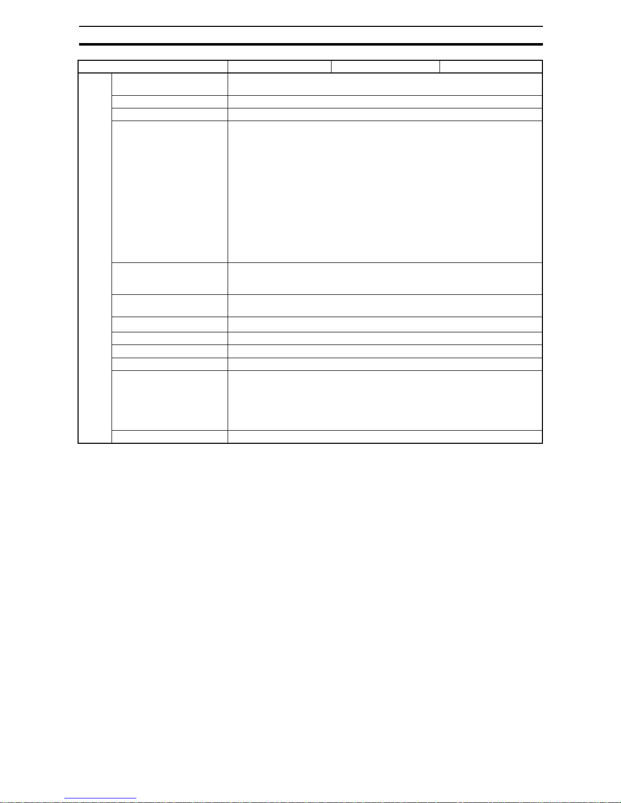
27
Specifications Section 2-3
Note (1) Do not use an inverter output for the Pow er Supply. Inverters with an out-
put frequency of 50/60 Hz are available, but the rise in the internal tem-
perature of the Power Supply may result in ignition or burning.
(2) Refer to Derating Curve on pagexiv for details.
(3) If the output voltage adjuster (V. ADJ) is turned, the voltage will increase
by more than 10% of the voltage adjustment range. When adjusting the
output voltage, confirm the actual output voltage from the Power Supply
and be sure that the load is not damaged. If the output voltage exceeds
28.8 V, all branch outputs will be cut off.
(4) Rated input and output conditions: Rated input voltage, rated frequency,
rated output voltage, rated total output current, and maximum cutoff out-
put current.
(5) 100% load conditions: Rated output voltage, rated total output current,
and maximum cutoff output current.
Others Ambient operating tempera-
ture
Refer to the derating curve (no icing or condensation). (See note 2.)
Storage temperature −25 5o 65°C
Ambient operating humidity 25% to 85% (storage: 25% to 90%)
Withstand voltage 3.0 kVAC for 1 min between all input terminals collectively and all branch output,
all I/O signal, and all communications terminals collectively (detection current:
20 mA)
2.0 kVAC for 1 min between all inputs and protective earth (Detection current:
20 mA)
1.0 kVAC for 1 min between protective earth and all branch output, all I/O signal,
and all communications terminals collectively (Detection current: 30 mA)
500 VAC for 1 min between all branch output and all I/O signal/communications
terminals collectively (Detection current: 20 mA)
500 VAC for 1 min between all I/O signal terminals collectively and communications terminals collectively (Detection current: 20 mA)
500 VAC for 1 min between all I/O signal terminals collectively and all output signal terminals collectively (detection current: 20 mA)
Insulation resistance 100 MΩ min. at 500 VDC between the protective earth terminal or all input termi-
nals collectively and all branch output, all I/O signal, and all communications terminals collectively
Vibration resistance No abnormality after 10 to 55 Hz at 0.375-mm single amplitude for 2 h each in 3
directions.
Shock resistance
No abnormality after 150 m/s
2
3 times each in 6 directions.
Output indicator Provided (Color: green)
Conducted EMI Conforms to EN 61204-3 Class A and FCC Class A.
Radiated EMI Conforms to EN 61204-3 Class A.
Safety standards cULus: UL508 (Listing. Class2: Per UL1310), CSA C22.2 No.107.1 (Class2: Per
CSA C22.2 No.223)
cURus: UL60950-1, CSA C22.2 No.60950-1
EN: EN50178, EN60950-1
VDE: VDE0160, VDE0805 Teil1
Weight 2,400 g max.
Item Model S8AS-48008 S8AS-48008N S8AS-48008R
Page 46

28
Specifications Section 2-3
External Output and External Tripping Input Specifications
The S8AS has 4 external outputs: the Tripping Alarm Output (TRP), Undervoltage Detection Output (LOW), Maintenance Forecast Monitor Output
(LFE), and Over-temperature Output (TMP). It also has an External Tripping
Input (TRG).
I/O Circuit Configuration
Note When a branch output is cut off with the External Tripping Input, it cuts off
power to the branch output even faster than turning OFF the S8AS's power
supply.
TRG+
TRG−
TRP
LOW
TMP
LFE
Output common
Tripping Alarm
Output circuit
Over-temperature
Output circuit
External Tripping
Input circuit
Undervoltage
Detection Output
circuit
Maintenance
Forecast Monitor
Output circuit
Name Circuit configuration I/O specifications
Tripping Alarm Output (TRP),
Undervoltage Detection Output (LOW), Maintenance Forecast Monitor Output (LFE) and
Over-temperature Output
(TMP)
Note A photo relay with a
photo MOS-FET and
infrared diode coupling
is used.
Output circuit 30 VDC and 50 mA
max.
External Tripping Input (TRG) Input circuit 19.2 to 30.0 VDC
Minimum signal width:
10 ms
TRP
LOW
LFE
TMP
COM
From internal power supply circuit
Signal from CPU
TRG (+)
TRG (−)
Page 47

29
Basic Function Details Section 2-4
2-4 Basic Function Details
2-4-1 Voltage Monitoring and Protection Functions
Abnormal Voltage
Tripping
When the output voltage converted from AC to DC exceeds 28.8 V, all of the
branch outputs will be cut off simultaneously and a TRP alarm will be output.
The seven-segment display will show error code A10.
It is not necessary for the user to set any parameters for this function.
Undervoltage
Detection
An undervoltage detection threshold can be set between 18.0 and 26.4 V.
Operation • If the output voltage falls below the detection threshold, the seven-seg-
ment display will show the error code A21 and the voltage value, and the
Undervoltage Detection Output (LOW) will turn OFF within 100 ms.
• The error display and Alarm Output can be reset when the voltage has
been above the detection threshold +0.3 V for 500 ms longer.
Tripping
operation
Seven-segment display Outputs Conditions
required to reset
28.8 VDC min.
20 ms max.
Alternately displays error
code A10 and the voltage.
The T ripping Alarm
Output (TRP) photoswitch output
turns OFF.
Voltage below
28.5 V and after
tripping (15 s has
elapsed after previous reset.)
24-VDC output voltage
Branch output
TRP output
Reset possible
20 ms
max.
28.8 V
28.5 V
Setting
range
Default
value
Operation Seven -
segment
display
Outputs Conditions
required to
reset
18.0 to
26.4 VDC
20.0 V When the
voltage is
lower than the
detection
threshold continuously for
80 ms or
more, the
alarm is output within
100 ms.
Alternately
displays error
code A21 and
the voltage.
The Undervoltage
Detection
Output (LOW)
photoswitch
turns OFF.
Voltage abov e
the detection
threshold
+0.3 V continuously for at
least 500 ms.
Page 48

30
Basic Function Details Section 2-4
2-4-2 Over-current Protection Functions
Abnormal Current
Tripping Function
When an abnormal current is detected, the S8AS cuts off the branch outputs
via semiconductor relays.
Each branch output's tripping current can be set between 0.5 and 3.8 A (in
0.1-A increments).
One of the follo wing three detection methods can be selected for each branch
in order to detect abnormal currents (except for the S8AS-24006N/48008N,
which always use the same detection method.)
• Standard detection (tripping within 100 ms)
• Instantaneous detection (tripping within 20 ms)
• Extended time detection (tripping within 1,000 ms)
(V-U) +0.3 V
V-U: Undervoltage
detection threshold
Undervoltage detection output (LOW)
100 ms
500 ms
Power
supply
voltage
Reset possible
Connected
Not connected
Connected
Reset signal
Undervoltage
alarm output (LOW)
Branch output
voltage
Undervoltage
detection threshold
Branch output
current
Power supply
voltage
Page 49

31
Basic Function Details Section 2-4
When the abnormal current is detected and branch output is cut off, the error
code (A11) and present current are displayed alternately on the seven-segment display and the Tripping Alarm Output (TRP) is turned OFF.
The status indicator of the branch output that was cut off will flash red.
To clear the error, eliminate the cause of the error, and then press the Reset
Key. Once an error has been reset, another reset operation cannot be performed for at least 15 seconds.
Setting
range
Default
value
Tripping
type
Operation Error code
and alarm
output
Conditions
required to
reset
0.5 to 3.8 A 3.8 A Standa rd When a current higher than
the set value is
detected, the
branch output
is cut off within
100 ms.
The error
codeA11
and current
are displayed alte rnately on the
seven-segment display and the
Tripping
Alarm Output (TRP)
photoswitch
output turns
OFF.
After tripping
(15 s has
elapsed
after the previous reset.)
Instantaneous
When a current higher than
the set value is
detected, the
branch output
is cut off within
20 ms.
Extended
time
When a current higher than
the set value is
detected, the
branch output
is cut off within
1,000 ms.
Abnormal current
tripping threshold
Current
Standard detection: 100 ms max.
Instantaneous detection: 20 ms max.
Extended detection 1,000 ms max
Tripping Alarm
Output (TRP)
Reset possible
Page 50
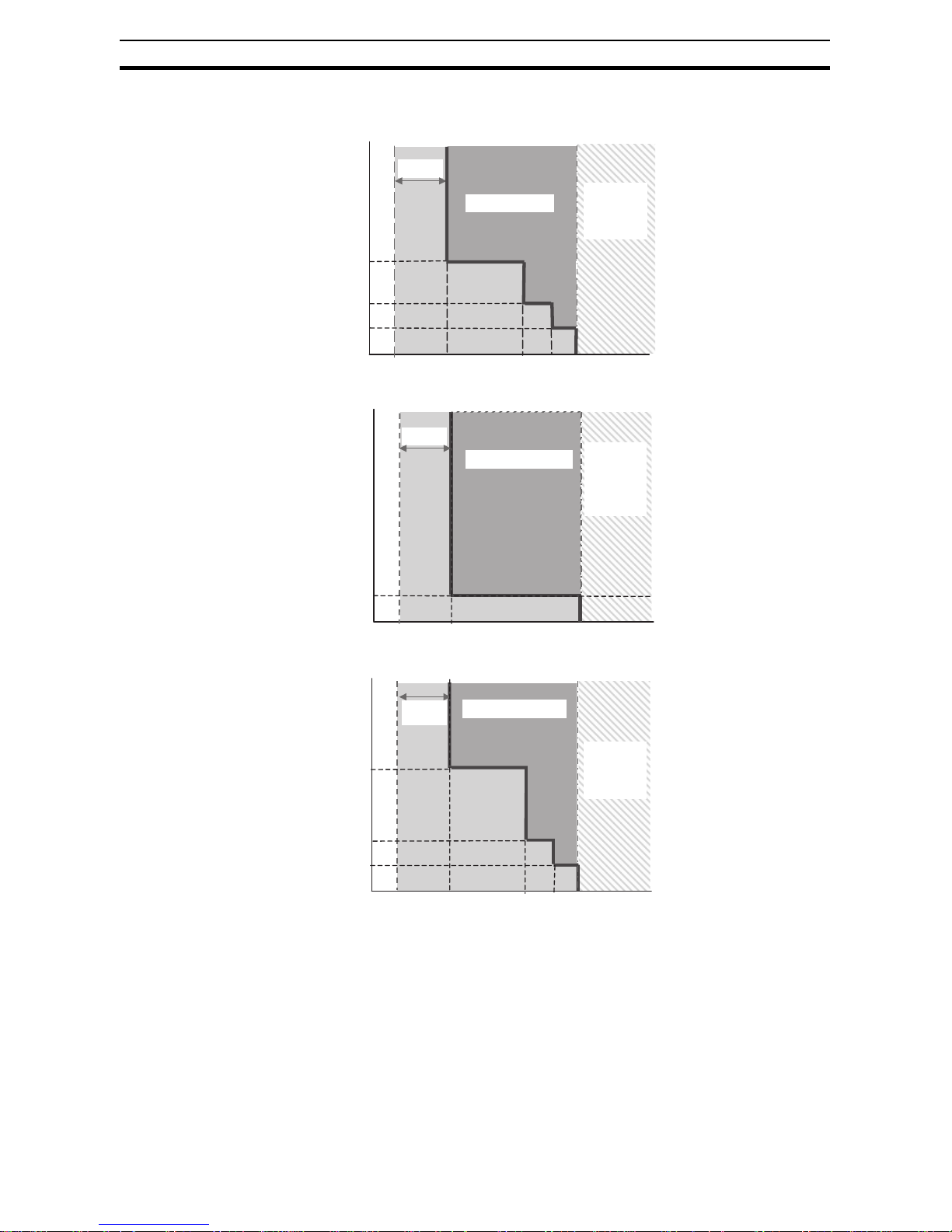
32
Basic Function Details Section 2-4
Current Tripping Characteristics
■ Standard Detection
■ Instantaneous Detection
■ Extended Detection
Note The S8AS contains a current-restricting circuit that prevents a cur-
rent above a specific v alue from flowing. The curren t is thus restricted during the time required to cut off the output.
Note After sampling and converting each branch output's current every 1 ms, the
S8AS processes the values in the CPU and controls the branch outp ut cutoffs. This method achieves high-speed, high-accuracy tripping. In addition, to
minimize the effects of excessive currents caused by short-circuits, the S8AS
is equipped with built-in current-limiting circuits. Consequently, there is a
Setting
range
Tripping region
Currentlimiting
by internal
circuits
Current (A)
100
Time (ms)
60
20
0.5
3.8 11
16 19
Tolerance of current tripping alarm threshold:
±0.3 A. When the tripping current (0.5 to
3.8 A) is detected, it is
cut off within 100 ms.
20
0.5
3.8
19
Setting
range
Tripping region
Currentlimiting
by internal
circuits
Current (A)
Time (ms)
Tolerance of current tripping alarm threshold:
±0.3 A. When the tripping current (0.5 to
3.8 A) is detected, it is
cut off within 20 ms.
20
0.5
3.8
19
60
1,000
11
16
Setting
range
Tripping region
Currentlimiting
by internal
circuits
Current (A)
Time (ms)
Tolerance of current tripping alarm threshold:
±0.3 A.When the tripping current (0.5 to
3.8 A) is detected, it is
cut off within 1,000 ms.
Page 51

33
Basic Function Details Section 2-4
region in which the current is limited, as shown in the current tripping characteristics graphs.
Abnormal Total Current Tripping Function
The S8AS monitors the total output current as well as the branch output currents. When the total output current exceeds the set value, all branch outputs
will be cut off. There are a number of conditions for the tripping current and
time. If even one of these conditions is detected, the abnormal total current
tripping function will be activated. The following tab le outlines the tripping conditions. (Input voltage range: 200 to 240 VAC)
−: Not applicable
Note (1) If the input voltage range is not within the values specified above or the
total output current exceeds the maximum peak current value, internal
operation will become unstable and the branch outputs may be cut off.
(2) Maintain the total current for normal operation after the load de vices hav e
started to within the rated ranges.
(3) Do not allow a peak current to flow again for at least 60 seconds after a
peak current has exceeded the rated current.
Current value
Time
Example sampling chart
Converted digital value
Current actually flowing
1 ms sampling period
Power-ON
time (s)
Total current (A) Operation Error code and
alarm output
Conditions
required to
reset
240W 480W
1 s min. --- 27 A When the total
current reaches
these values, all
branches will be
cut off within 20
ms.
The error code
A12 will flash on
the seven-segment display
and the Tripping Alarm Output (TRP)
photoswitch output will turn
OFF.
After tripping
(15 s has
elapsed after
the previous
reset.)
2 s min. 17 A 25 A
5 s min. 15 A 22.5 A
10 s min. 13 A −
20 s min. 12 A −
Page 52

34
Basic Function Details Section 2-4
Startup Delay Normally, a large inrush current may run through the system when equipment
starts. Tripping operation can be disabled for a short time after the semiconductor relay goes ON in order to prevent this inrush current from being
detected as an abnormal current and cutting off operation. This temporary
disabling of the tripping function is called the startup delay.
Note The star tup delay disables the tripping operation for the specified
period of time. The inrush current during th is time can be di spla ye d
as the peak output current. The S8AS, how ev er , contains a curren trestricting circuit, so the peak value is not necessarily an accurate
measure of the peak inrush current of the connected device.
Safety Functions
Short-circuit Protection
Fuse
If an error occurs that prevents the semiconductor relay from cutting off a
branch output, the short-circuit protection fuse will blow to protect the circuit.
Note If the fuse blows, that branch output cannot be used.
Thermal Fuse If an error occurs that prevents the semiconductor relay from cutting off a
branch output and the temperature of the S8AS's internal resistors rises
abnormally high, the S8AS's thermal fuse will blow to prevent a fire hazard.
Note If the fuse blows, that branch circuit cannot be used.
2-4-3 Maintenance Forecast Monitor Function
The maintenance forecast monitor function calculates the replacemen t time
from the power-ON time and internal temperature. The maintenance forecast
monitor output (LFE) will operate when the calculated value reaches the set
value. (The set value is fixed at 0.5 years for the S8AS-24006N/48008N and
cannot be changed.) When the maintenance forecast monitor output (LFE) is
turned ON, the error code A23 and the estimated replacement time are displayed alte rnately on the seven-segment display.
Tripping Alarm
Output (TRP)
OFF (open)
ON (closed)
Startup delay (40 ms)
100 ms max. (standard detection)
Branch output
current
Branch output
voltage
Power supply
voltage
No cutoff during startup delay even if set value is exceeded.
Abnormal current tripping threshold
OFF (open)
Initial capacity
Electrolytic
capacitor capacity
Capacity at replacement time
ful
hlf
4.5
(L-0.5)
1.5
1.0
0.5
0.0
Seven-segment display
Maintenance forecast
monitor output
LFE output when L = 1.0
5.0 2.0 1.5
0.5 0
1.0
Page 53

35
Basic Function Details Section 2-4
When the life of the electrolytic capacitor (expected value = 10 yr) has halved,
the remaining life span (5 yr) is divided into 10 levels (in 0.5-yr increments).
These levels are used by the maintenance forecast monitor output (LFE) to
display the number of years that are left before the Power Supply needs to be
replaced.
Note The expected life span of the S8AS is 10 years, but it will change
depending on the amount of time it is in operat ion and t he ambient
temperature.
2-4-4 Over-temperature Output
When the temperature exceeds the set value continuously for more than 1 s,
the seven-segment display will show error code A30 and the Over-temperature Output (TMP) will go OFF.
The error display and Over-temperature Output are reset automatically when
the temperature has been below the set value minus 3°C for more than 5 s.
Over-temperature Output
(TMP)
When the temperature falls below the set value minus 3°C, the over-temperature output automatically turns ON.
• The over-temperature output (T MP) can be used to star t an exhaust fan
or air conditioner to reduce the temperature in the control panel.
• The initial value is set at 90°C so that the over-temperature output is
essentially disabled at the beginning.
Example Application The output is normally closed (ON) and goes OFF when there is an error, so
receive the TMP output through an auxiliary relay. In addition, the output will
go ON momentarily when the power is turned ON, so receive the output
through a time-delay relay. (For details, refer to page 50.)
Setting
range
Default
value
Operation Seven-
segment
display
Outputs Conditions
required to
reset
25 to 90°C90°C The output is
turned OFF
when the temperature higher
than the set
value continuously for more
than 1 s.
Alternately
displays
error code
A30 and the
temperature(°C).
The Overtemperature
Output
(TMP) photoswitch output turns
OFF.
Reset automatically
when the
temperature
falls below
the set value
minus 3°C.
t: Over-temperature output threshold
(t-3)°C
Temperature °C
Error display and
Over-temperature
Output (TMP)
Automatic reset
1 s
5 s
Page 54

36
Basic Function Details Section 2-4
Relationship between
Control Panel
Temperature and S8AS
Internal Temperature
The internal temperature of the S8AS is displayed. This is not necessarily the
same as the ambient temperature of the S8AS or the temperature inside the
control panel. The difference between the internal temperature of the S8AS
and the ambient temperature depends on the current flowing through the
S8AS. Consider this difference in the application.
The following graph provides reference information on the displayed internal
temperature and the ambient temperature.
Conditions: The same current was output from all branch outputs in a con-
stant-temperature bath held at a const ant temperature
TMP
COM
X
TR
TR
24 VDC
S8AS
Fan, etc.
IM
Page 55

37
Startup Sequence Function Section 2-5
■ 240 W
■ 480 W
2-5 Startup Sequence Function
The inrush current may cause a voltage drop if all of the branch outputs are
connected simultaneously and there is little spare capacity in the power supply or the loads connected to the branch output s are capacitiv e loads . A significant voltage drop may cause an output to be cut off. In this case, a time delay
can be applied between the connectio ns of the b ran ch outputs t o minimiz e the
voltage drop.
Note (1) The time delay can be set between 0.0 and 99.9 s. (If the delay is set to
0.0 s, the startup sequence will not operate and the branch output will be
connected immediately.)
(2) The startup sequence is designed for the four branch outputs on one
S8AS. It does not provide time synchron ization between output s on more
than one S8AS.
After the power supply is turned ON and the self-diagnostics are performed,
the S8AS will start connecting the branch output according to their preset
startup sequence times.
Ambient temperature (°C)
Displayed temperature (°C)
0.5 A per branch (total output current: 3 A)
1.67 A per branch (total output current: 10 A)
100
80
60
40
20
0
−20
−20 −10 0 10 20 30 40 50 60 70
Ambient temperature (°C)
Displayed temperature (°C)
0.5 A per branch (total output current: 4 A)
2.5 A per branch (total output current: 20 A)
100
80
60
40
20
0
−20
−20 −10 0 10 20 30 40 50 60 70
Page 56

38
Shutdown Sequence Function Section 2-6
• The branch output's status indicator will flash green during the startup
sequence time until it is connected.
• The startup sequence's operation can be verified in Test Mode. For
details, refer to 5-3 Checking Sequence Operation.
• The startup sequence for models with unchangeable settings
(S8AS-24006N/48008N) cannot be changed.
Note The startup sequence functions in the following processes:
• Connecting when power is turned ON
• Reconnecting during a reset operation
• Simultaneous conn ec tio n of all outp u ts in Test Mode
2-6 Shutdown Sequence Function
When the S8AS's input power supply is turned OFF, all of the branch outputs
are turned OFF (disconnected) simultaneously. On the other hand, when the
branch outputs are cut off by the external tripping input or com munications, a
time delay can be applied between the branch output disconnections.
Note (1) The time delay can be set between 0.0 and 99.9 s. (If the delay is set to
0.0 s, the startup sequence will not operate and the branch output will be
cut off immediately.)
(2) The shutdown sequence is designed for the four branch outputs on one
S8AS. It does not provide time synchron ization between output s on more
than one S8AS.
Branch output
number
12345678
Setting time 0.0 s 0.4 s 0.8 s 1.2 s 1.6 s 2.0 s 2.4 s 2.8 s
Setting time
Power supply
voltage
Branch output 1
voltage
Branch output 2
voltage
Branch output 3
voltage
Self-diagnostics (0.5 s min.)
Setting time
Setting time
Setting time
Branch output n voltage
(n: maximum branch
output number)
Page 57

39
External Tripping Input Function Section 2-7
(3) When operation is cut off due to an abnormal voltage (above 28.8 V), all
of the branch outputs will be cut off simultaneously.
(4) The shutdown sequence function will operate on a branch output only if
the external tripping input is enabled for that branch output. For details,
refer to Tripping Input Trigger Setting: TRG (Trigger) on page 68.
(5) The shutdown sequence setting times f or all branch outputs f or the S8AS-
24006N/48008N are set to 0.0 s and cannot be changed.
• The shutdown sequence's operation can be verified in Test Mode. For
details, refer to 5-3 Checking Sequence Operation.
Note The shutdown sequence functions in the following processes:
• Cutoff processing for the external tripping input
• Simultaneous cuto ff of all outp uts in Test Mode
2-7 External Tripping Input Function
The external tripping input (TRG) can be used to cut off or reconnect branch
outputs using an external input signal. The following settings are required to
use this function.
The external tripping input is enabled and tripping type for the S8AS-24006N/
48008N is set to EGE and these settings cannot be changed.
External tripping input
Branch output 1 voltage
Branch output 2 voltage
Branch output 3 voltage
Setting time
Setting time
Setting time
Setting time
Within 20 ms
Branch output n voltage
(n: maximum branch
output number)
Item Function Settings
External tripping
input activation
Enables the external tripping
input (TRG) function for each
branch.
ON (enabled)
OFF (disabled)
Tripping trigger type Sets the external tripping
input trigger signal type.
EGE (edge trigger)
LVL (level trigger)
Page 58

40
External Tripping Input Function Section 2-7
Tripping Trigger Type: Edge Trigger (EGE)
If the trigger signal (TRG) stays OFF f or more tha n 10 ms and the branch output is disconnected for more than 500 ms, the reset input can be received.
Tripping Trigger Type: Level Trigger (LVL)
a
Reset *
Branch output B voltage
(tripping input disabled)
Trigger signal
Branch output A voltage
(tripping input enabled)
10 ms
500 ms
a: 20 ms + Shutdown sequence setting time
*: Connected after startup sequence setting time has elapsed.
a b
Branch output B voltage
(tripping input disabled)
Trigger signal
Branch output A voltage
(tripping input enabled)
a: 20 ms + Shutdown sequence setting time
b: 20 ms + Startup sequence setting time
Page 59

41
SECTION 3
Installation and Wiring
This section describes how to install and wire the S8AS.
3-1 Installing the S8AS . . . . . . . . . . . . . . . . . . . . . . . . . . . . . . . . . . . . . . . . . . . . . 42
3-2 Installation. . . . . . . . . . . . . . . . . . . . . . . . . . . . . . . . . . . . . . . . . . . . . . . . . . . . 44
3-3 Power Supply and Input/Output Wiring . . . . . . . . . . . . . . . . . . . . . . . . . . . . . 47
3-4 RS-485 Port Wiring. . . . . . . . . . . . . . . . . . . . . . . . . . . . . . . . . . . . . . . . . . . . . 52
Page 60

42
Installing the S8AS Section 3-1
3-1 Installing the S8AS
Installation and
Wiring Precautions
To increase the S8AS system's reliability and take full advantage of the
S8AS's functions, observe the following precautions when installing the S8AS.
Installation Site Avoid locations with any of the following conditions when installing the S8AS.
• Locations subject to a temperature below −10°C or over 60°C
• Locations subject to a humidity below 25% or over 85% (no condensa tion/
icing)
• Locations subject to direct sunlight
• Locations subject to exposure to liquids, debris, or corrosive gases
• Locations subject to severe shock or vibration
• Locations near equipment that generates strong high-frequency noise or
surges
Always enclose or protect the S8AS sufficiently in the following locations.
• Locations subject to static electricity or other forms of noise.
• Locations subject to strong electromagnetic fields.
• Locations subject to possible exposure to radioactivity.
• Locations close to power lines.
Installation in
Cabinets or Control
Panels
When the S8AS is being installed in a cabinet or control panel, always provide
suitable ambient conditions as well as access for operation and maintenance.
Ambient Temperature The operating temperature range for the S8AS is −10°C to 60°C. Observe the
following precautions.
• Provide enough space for good air flow.
• Do not install the S8AS above equipment that generates a large amount
of heat, such as heaters, transformers, or high-capacity resistors.
• If the ambient temperature in the cabinet may exceed 60°C, install an
exhaust fan or air conditioner and use the Over-temperature Output to
operate the cooling equipment.
• Mount the S8AS at least 20 mm away from heat sources.
• Leave at least 75 mm between the S8AS and other devices above and
below it.
S8AS
Fan
Control
panel
Vent
Page 61

43
Installing the S8AS Section 3-1
Other control devices
75 mm min.
75 mm min.
20 mm min.
Air flow
Other control devices
Page 62

44
Installation Section 3-2
3-2 Installation
When mounting the S8AS in a panel, use DIN Rail. Su rf ace installati on cannot
be used.
Mounting in a Panel • The S8AS must be installed in the orientation shown below to ensure
adequate cooling.
• Do not install the S8AS in any of the following orientations.
Incorrect
Incorrect
Incorrect
Incorrect
Page 63

45
Installation Section 3-2
External Dimensions
S8AS-24006@ (240-W
Model with 6 Branch
Outputs)
S8AS-48008@ (480-W
Model with 8 Branch
Outputs)
Attachment to the DIN
Rail
The S8AS attaches to the DIN Rail with one snap. Hang the S8AS on the top
of the DIN Rail with the installation notch on the back of the S8AS, pivot the
S8AS downward, and press until the S8AS locks securely on the Rail.
1,2,3... 1. Pull out the two lock levers on the S8AS.
Lower the S8AS so that the installation notch hooks onto the top of the DIN
Rail.
YrsA
543216
Vs˚C
S8AS-24006
POWER SUPPLY
+V
-V
-V
RS485
A(-) B(+)
50/60Hz AC100-240V 3.8A
INPUT
NL
543216
Class2
OUTPUT
DC 24V 3.8A
- 5- 4- 3- 2- 1 - 6
+ 5+ 4+ 3+ 2+ 1 + 6
V.ADJDC ON
COMTMP
TRG
LFELOWTRP
+-
142.4
115
4.5
124.7
122
34.9
131.8 5.08
10
160
Three, M3.5 square washers
M4 square washers
(sliding: 15 max.)
YrsA
543216
7 8
Vs˚C
S8AS-48008
POWER SUPPLY
76543218
50/60Hz AC100-480V 3.8A
INPUT
NL
COMTMP
TRG
LFELOWTRP
+-
V.ADJDC ON
+ 5+ 4+ 3+ 2+ 1 + 6 + 7 + 8
- 5- 4- 3- 2- 1 - 6 - 7 - 8
+V
-V
-V
Class2
OUTPUT
DC 24V 3.8A
RS485
A(-) B(+)
10
115
4.5
124.7
122
34.9
131.9 5.08
230
142.4
Three, M3.5 square washers
M4 square washers
(sliding: 15 max.)
2. Hook the installation notch on the top of the DIN Rail.
1. Pull out the lock levers.
Page 64

46
Installation Section 3-2
2. Press the S8AS onto the DIN Rail and push in the lock levers .
Press the lock levers until the locks engage securely.
After the S8AS is mounted on the DIN Rail, attach an End Plate on each
side of the Power Supply to secure it in place.
■ Recommended End Plate
Removal When removing the S8AS from the DIN Rail, pull the lock lever down with a
flat-blade screwdriver and pivot the S8AS upward to remov e it.
3. Press the S8AS firmly onto the DIN Rail
4. Press in the lock levers until the locks en
gag
e securely.
PFP-M
4.8
1.3
35.5 35.3
1.8
1
1.8
10
6.2
M4 spring
washer
50
11.5
M4 × 8
Pan-head
screw
10
CH
SEL
ENT
Page 65

47
Power Supply and Input/Output Wiring Section 3-3
3-3 Power Supply and Input/Output Wiring
Wiring Precautions • When wiring, cover the top of the S8AS to prevent wire strands from
entering. After completing the wiring, be sure to remov e the co v er to a v oi d
overheating.
• Use the following crimp terminals on the power input wires and tighten the
terminal screws to the specified torque.
AC input terminals and protective earth (PE) terminals: M3.5
Negative branch output terminals: M4
Selecting the Wire
Refer to the following table when selecting wire to use for the power supply.
8 mm max.
8 mm max.
Terminals Name Recommended
wire diameter
Wire type Torque Wire
stripping
length
Screw terminals
AC input terminals
and protective earth
(PE) terminal
AWG14 to
AWG16 (Crosssection area:
1.309 to
2.081 mm
2
)
Solid or
stranded
1.08 N·m
(9.6 in lb)
8 to
10 mm
Branch output terminals (−), UL Standard
AWG12 to
AWG14 (Crosssection area:
2.081 to
3.309 mm
2
)
Solid or
stranded
1.2 N·m
(10.6 in lb)
8 to
10 mm
Branch output terminals (−), CSA Standard
AWG12 to
AWG20 (Crosssection area:
0.517 to
3.309 mm
2
)
Solid or
stranded
1.0 N·m
(8.8 in lb)
8 to
10 mm
Screwless terminals
Positive branch output terminals, negative branch output
terminals, I/O signal
terminals, and communications terminals
AWG12 to
AWG24 (Crosssection area:
0.2 to 2.5 mm
2
)
Solid or
stranded
--- 10 mm
AWG Cross-sec-
tional area
(mm
2
)
Configura-
tion
(wires/mm)
Voltage
drop per A
(mV/m)
Max. recommended current (A)
UL1007
(300 V 80°C)
UL1015
(600 V 105°C)
30 0.051 7/0.102 358 0.12 --28 0.081 7/0.127 222 0.15 0.2
26 0.129 7/0.16 140 0.35 0.5
24 0.205 11/0.16 88.9 0.7 1.0
22 0.326 17/0.16 57.5 1.4 2.0
20 0.517 26/0.16 37.6 2.8 4.0
18 0.823 43/0.16 22.8 4.2 6.0
16 1.309 54/0.18 14.9 5.6 8.0
14 2.081 41/0.26 9.5 --- 12.0
12 3.309 65/0.26 6.0 --- 22.0
10 5.262 104/0.26 3.8 --- 35.0
Page 66

48
Power Supply and Input/Output Wiring Section 3-3
Maximum Recommended Current:
The values listed in the table above are fo r bundles of up to 4 wires. If 5 or
more wires are bundled together, reduce the max. current to 80% of the listed
current.
The following chart shows only the relationship between the voltage drop per
meter and the current and wire length. Be sure that the current actually being
used does not exceed the max. recommended current.
Voltage Drop per Meter
(UL1015 Heat-resistant
PVC Wire)
Wiring the AC Input
and Protective Earth
(PE) Terminals
• Use 100 to 240 VAC (85 to 264 VAC) 50/60 Hz power supply with minimal
voltage fluctuation. Use wires with a hi gh current carrying capacities.
• Be sure to connect the protective earth (PE) terminal to ground to prevent
electric shock and malfunction.
Wiring the Branch
Outputs
Two positive and two negative terminals are used for each branch output.
Voltage drop (mV)
The current
shown is the allowed current.
In actual applications, use a
current below
the maximum
recommended
current.
Current (A)
M3.5
Power supply terminal block
100 to 200 VAC 50/60 Hz
(commercial power supply)
L
N
Page 67

49
Power Supply and Input/Output Wiring Section 3-3
■ Wiring the Branch Output Connector
240 W
480 W
Note You may connect the positive terminals or the negative terminals of the same
branch output in parallel, but do not connect them with other branch outputs.
The lock screws on both sides of the branch output connector are loose when
shipped from the factory. Tighten them securely after you complete the wiring.
Wiring the Terminal Block
Connectors
Use a solid or stranded wire. If you are using stranded wire, twist the end
before connecting it to make a clean connection.
• Strip the wire for approximately 10 mm from the end.
• Inser t a flat-blade screwdriver into the release button to release the lock.
Insert the wire into the round hole, and then release the button to lock the
wire in place.
+
−
+
−
Branch
output 1
+
Branch
circuit 1
Branch output common (−)
Branch
output 2
+
Branch
output 3
+
Branch
output 4
+
Branch
output 5
+
Branch
output 6
+
Branch
output 1
−
Branch
output 2
−
Branch
output 3
−
Branch
output 4
−
Branch
output 5
−
Branch
output 6
−
Branch
circuit 6
+
−
+
−
Branch
output 1
+
Branch
circuit 1
Branch output common (−)
Branch
output 2
+
Branch
output 3
+
Branch
output 4
+
Branch
output 5
+
Branch
output 6
+
Branch
output 1
−
Branch
output 2
−
Branch
output 3
−
Branch
output 4
−
Branch
output 5
−
Branch
output 6
−
Branch
circuit 8
Branch output
common (−)
Branch
output 7
+
Branch
output 8
+
Branch
output 7
−
Branch
output 8
−
10 mm
Release Button
Page 68

50
Power Supply and Input/Output Wiring Section 3-3
• When inserting the wire, make sure that the stripped portion of the wire is
fully inserted and not left exposed.
• After completing a connection, lightly pull on the wire to make sure that it
has been locked in properly.
Wiring the External
Outputs and External
Tripping Input
The TRP, LOW, LFE, and TMP outputs operate as normally closed outputs,
which are OFF when the power is OFF, ON during normal operation, and OFF
when an error has occurred. If you want to use these an external output as a
normally open output, invert the signal through an auxiliary relay (X). When
doing so, the alarm may turn ON momentarily when the power supply is
turned ON. To prevent this, delay the signal through the delay relay (TR).
The branch output is cut off when the External Tripping Input (TRG) is ON
(connected).
No. Name Function
1 TRP Tripping Alarm
Output
The photoswitch output turns OFF when the
branch output is cut off due to an abnormal
voltage or abnormal current.
2 LOW Under voltage
Detection Output
The photoswitch output turns OFF when the
output voltage drops below the set value.
3 LFE Maintenance
Forecast Monitor
Output
The photoswitch output turns OFF when the
estimated replacement time drops below the
set value.
4 TMP Over-temperature
Output
The photoswitch output turns OFF when the
S8AS's internal temperature exceeds the
over-temperature output threshold.
5 COM Output Common Common terminal for the four outputs
described above.
6 TRG (+) External Tripping
Input
Branch outputs can be cut off from an external operation. (The shutdown sequence is
applied in this case.)
7TRG (−)
TRP LOW LFE TMP COM TRG(+) TRG(−)
X1 X2
X3
X4
TR
X1 X2 X3 X
4
TR
Delay Relay
Tripping Alarm
Output
Undervoltage
Detection Output
Maintenance
Forecast Monitor
Output
Over-temperature
Output
Output Common
Positive Tripping
Input (+)
Negative Tripping
Input (−)
Tripping Input
*
* Output terminals do not have polarity.
Page 69

51
Power Supply and Input/Output Wiring Section 3-3
■ Internal Circuits
Output
circuits
30 VDC, 50 mA max.,
photoswitch output
Input
circuit
19.2 to 30.0 VDC
Minimum signal width: 10 ms
TRG+
TRG−
TRP
LOW
TMP
LFE
Output
common
Tripping Alarm
Output circuit
Undervoltage
Detection
Output circuit
Maintenance
Forecast Monitor
Output circuit
External
Tripping Input
circuit
Over-temperature Output circuit
Page 70

52
RS-485 Port Wiring Section 3-4
3-4 RS-485 Port Wiring
Wiring the RS-485
Port
S8AS models with communications have an RS-485 port that can be connected with a host computer or controller.
Example Connection to a Host Computer
• The connection format is 1:1 or 1:N. Up to 32 nodes can be connected to
a host computer.
• Insert a Cramp Filter (E04SR301334 manufactured by SEIWA) in the
cable as a countermeasure against noise.
• The node on each end of the transmission path, including the host computer, mu st be spe cified as an end no de (i.e., terminating resistor must be
connected.) Use terminating resistor of 120 Ω (1/2 W) with a combined
resistance of at least 54 Ω.
• Make sure that the communications specifications are set to the same
values for the host computer and the S8AS. (Refer to 4-1 Parameter
Table.) When connecting in a 1:N format, make sure that the communications specifications except for the communications unit number are set to
the same values for all nodes. A unique communications unit number
must be set for each node.
• Strip 10 mm from the ends of the RS485 cable's wires.
• Press the terminal's release button all
the way in and insert the wire into the
round wire hole. When the wire is
inserted, be sure that the wire conductor is not exposed.
• Release the release button to lock the
wire in place.
• After wiring, verify that the wires are
securely locked in the terminals.
Press the Release
Button all of the
way in and insert
the wire.
10 mm
A (−)
B (+)
1 PWR SG 7
2 NC RDA(−)8
3 SG SDA(−)9
4 PWR NC 10
5 SD 11
6 RD 12
S8AS
CD 1
RD 2
SD 3
ER 4
SG 5
DR 6
RS 7
CS 8
C1 9
S8AS
RS-485
RS-485
Clamp filter
RDB(+)
SDB(+)
A(−)
B(+)
A(−)
B(+)
Computer
RS-232C
interface
Name
Pin
Name
Pin
K3SC-10
Power Supply
• AC model:
100 to 240 VAC
• DC model:
24 VDC or 24 VAC
(50 to 60 Hz)
Name
Pin
Note: Terminating resistor (120 Ω, 1/2 W recommended)
We recommend
twisting the RS-485
communications lines.
(See note.)
(See
note.)
(See
note.)
Page 71

53
SECTION 4
Parameter Settings
This section explains how to set S8AS parameters.
4-1 Parameter Table. . . . . . . . . . . . . . . . . . . . . . . . . . . . . . . . . . . . . . . . . . . . . . . . 54
4-2 Switching the Operating Mode. . . . . . . . . . . . . . . . . . . . . . . . . . . . . . . . . . . . 56
4-3 Changing the Protection Level . . . . . . . . . . . . . . . . . . . . . . . . . . . . . . . . . . . . 59
4-4 Switching to Setting Mode . . . . . . . . . . . . . . . . . . . . . . . . . . . . . . . . . . . . . . . 60
4-5 Individual Branch Output Settings . . . . . . . . . . . . . . . . . . . . . . . . . . . . . . . . . 61
4-6 Shared Parameter Settings. . . . . . . . . . . . . . . . . . . . . . . . . . . . . . . . . . . . . . . . 63
4-7 Special Settings and Communications Settings . . . . . . . . . . . . . . . . . . . . . . . 66
Page 72

54
Parameter Table Section 4-1
4-1 Parameter Table
The S8AS's operation is determined by the parameter settin gs . Each para meter is set to its default value, but each parameter should be checked and set
as required to adjust the S8AS for use in the system .
Parameters cannot be changed for the S8AS-24006N/48008N. Always use
the default values.
Parameter LED Indicators Setting range Default
value
Access in each
protection level
(See note 3.)
Seven-
segment
display
Unit
indica-
tor
Branch
output
indicator
210
Branch output 1Current tripping
threshold
c-v A Lit 0.5 to 3.8 A 3.8 A ∆ ❍❍
Current tripping
type
c-t A Lit USU: Standard
INS: Instantaneous
LNG: Extended
Standard
Extended
(See note
4.)
××❍
Branch output
2 to 8
Same as branch output 1
Undervoltage detection threshold v-u V --- 18.0 to
26.4 V
20.0 V ∆ ❍❍
Maintenance forecast monitor
output
lfe Yrs --- 0.0 to 5.0 yr 0.5 yr ∆ ❍❍
Over-temperature output threshold
tmp °C --- 25 to 90°C 90°C ∆ ❍❍
Startup
sequence
Individual branch
output settings
ups s Lit 0 to 99.9 s 0 s
(See note
1.)
××❍
Shutdown
sequence
Individual branch
output settings
dws s Lit 0 to 99.9 s 0 s ××❍
Tripping trigger input setting
Individual branch
output settings
trg --- Lit OFF
ON
ON ××❍
Tripping trigger type setting tg5 --- --- EGE: Output cut off
when status changes
from OFF to ON
L VL: Output cut off when
status changes from
OFF to ON, or ON to
OFF
EGE ××❍
Communications settings
(See note 2.)
Unit number uno --- --- 0 to 31 1 ××❍
Baud rate dps --- --- 48: 4,800 bps
96: 9,600 bps
9,600 bps
Data length len --- --- 7: 7 bits
8: 8 bits
7
Stop bits bit --- --- 1: 1 bit
2: 2 bits
2 bits
Parity pty --- --- NON: None
EVEN: Even
ODD: Odd
EVN
Send wait time syt --- --- 0 to 999 ms 0 ms
Reset input settings rse --- --- KEY: RST Key only
ALL: RST Key or reset
power supply
All ××❍
Page 73

55
Parameter Table Section 4-1
×: No access (The parameter cannot be set or displayed.)
∆: Read-only access
❍: Full access (The parameter can be set or displayed.)
Note (1) Parameters cannot be changed for the S8AS-24006N/48008N. Use the
default settings. For details, refer to 2-5 Startup Sequence Function.
(2) The communications settings can be changed for the S8AS-24006R/
48008R only. Changes to the parameters are valid after the power has
been turned OFF and ON again.
(3) For information changing the prot ection level, refer to 4-3 Changing the
Protection Level.
(4) The default setting for the S8AS-24006N/48008N is for an extended set-
ting.
Page 74

56
Switching the Operating Mode Section 4-2
4-2 Switching the Operating Mode
The following diagram illustrates mode transitions for the S8AS.
The S8AS's parameters are set in Setting Mode
Note (1) One of three protection levels can be set to restrict parameter read/write
access. Parameters cannot be changed for the S8AS-24006N/48008N.
For details, refer to 4-3 Changing the Protection Level.
(2) Parameter initialization sets all S8AS parameters to their default values.
Parameters cannot be changed for the S8AS-24006N/48008N. For de-
tails, refer to 4-1 Pa rameter Table.
(3) T est Mode can be entered only in protection level 0 or 1.
(4) The Setting Mode, Protection Level, and P arameter Initialization displa ys
cannot be accessed with models that do not permit changes in par ameter
settings (S8AS-24006N/48008N).
(5) If the Mode Selection Menu is entered from Test Mode and then the pow-
er is turned OFF before entering another operating mode, the S8AS will
start in Test Mode the next time it is started.
Starting for the First Time When the S8AS is started for the first time, it will enter Run Mode. The default
protection level is level 1, so the Parameter Initialization Display (INI) cannot
be entered without changing the protection level.
Starting for Normal
Operation
When the S8AS is started, it will enter Run Mode. If the power was turned OFF
while the S8AS was in Test Mode, it will start in Test Mode the next time it is
started.
The Protection Level or Parameter Initialization Display can be selected from
the Mode Selection Menu. These options will not be displayed for the S8AS24006N/48008N.
Switching to the Mode
Selection Menu
Press both the Up (SEL) Key ( ) and Down (CH) Key ( ) simultaneously
for 3 seconds to display the Mode Selection Menu.
Mode Selection Menu
Power ON
Press for 3 s
(See note 4.)
Test Mode (See note 3.)
Run Mode
Power ON
Setting Mode
Press for 3 s
Press for 3 s
Initialize Parameters ini (INI)
(See note 4.)
(See note 4.)
Select Protection Level prt (PRT)
Select T est Mode tst (TST)
Select Setting Mode set (SET)
Select Run Mode run (RUN)
S8AS was not in
Test Mode when
power went OFF.
(See note 5.)
Mode selection menu
The Initialize Parameters
command is displayed in
protection level 0 only.
· When started for the first time
· S8AS was not in Test Mode
when power went OFF.
(See note 5.)
Page 75

57
Switching the Operating Mode Section 4-2
Switching between Displays in the Mode Selection Menu
When the S8AS is switched to the Mode Selection Menu from Run Mode, the
seven-segment display will show “RUN.”
If the Key is pressed, SET will be displayed. If the Key is pressed at
this point, the S8AS will enter Setting Mode.
Refer to 4-4 Switching to Setting Mode to 4-7 Special Settings and Communi-
cations Settings.
Note This option will not be displayed f or models that do not permit changes
in parameter settings (S8AS-24006/48008N).
If the Key is pressed, TST will be displayed. If the Key is pressed at
this point, the S8AS will enter Test Mode.
Refer to SECTION 5 Trial Operation to Actual Operation.
Note If the protection level is set to level 2, this option will not be displayed
for any models.
If the Key is pressed, PRT (protect) will be displayed.
If the Key is pressed at this point, the S8AS will switch to the protection
level display.
Refer to 4-3 Changing the Protection Level for details on setting parameters.
Note This option will not be displayed for models that do not permit change
in parameter settings (S8AS-24006N/48008N).
If the protection level is set to lev el 0, INI will be displa yed when the Key is
pressed.
If the Key is pressed at this point, the S8AS will switch to the parameter
initialization display.
Note
1. This option will not be displayed for models that do not permit change in parameter settings (S8AS-24006N/48008N).
2. The default protection level is le v el 1. At this le vel, the INI option will not be
displayed for any models.
(If the Key is pressed, the S8AS will return to the RUN display.)
r u n
°C
123 4 56
V A Yrs s
s e t
1
2
3
4
5
6
V
A
Yrs
s
°C
t s t
1
2
3
4
5
6
V
A
Yrs
s
°C
p r t
1
2
3
4
5
6
V
A
Yrs
s
°C
i n i
1
2
3
4
5
6
V
A
Yrs
s
°C
Page 76

58
Switching the Operating Mode Section 4-2
Note The procedure for initializing parameters is given below. (Parameters cannot
be initialized for the S8AS-24006N/48008N.)
After the parameters have been initialized, the default settings will be in effect
and the initial power-ON status will be used.
• The operating mode will be Run Mode.
• All branch outputs will be connected.
• Protection level 1 will be used.
Press the Key from the initialize display (INI). The S8AS will switch
to the parameter initialization display.
If the Key is pressed, NO will be displayed. Initialization cannot be
performed from this display.
(The S8AS will automatically return to the Parameter Initialization Display (INI) if no key is pressed within 3 s.)
Press the Key . The display will change to YES . The parameters will
be initialized if the Key is pressed from this display.
(The S8AS will automatically return to the Parameter Initialization Display (INI) if no key is pressed within 3 s.)
Press the Key to start initializing parameters.
INI will flash on the display while parameters are being initialized. When
the display stops flashing, all parameters will have been initialized.
The operating mode will change to Run Mode.
i n i
1
2
3
4
5
6
V
A
Yrs
s
°C
n o
1
2
3
4
5
6
V
A
Yrs
s
°C
()
y e s
1
2
3
4
5
6
V
A
Yrs
s
°C
Flashing
i n i
i n i
1
2
3
4
5
6
V
A
Yrs
s
°C
2 4. 0
1
2
3
4
5
6
V
A
Yrs
s
°C
Page 77
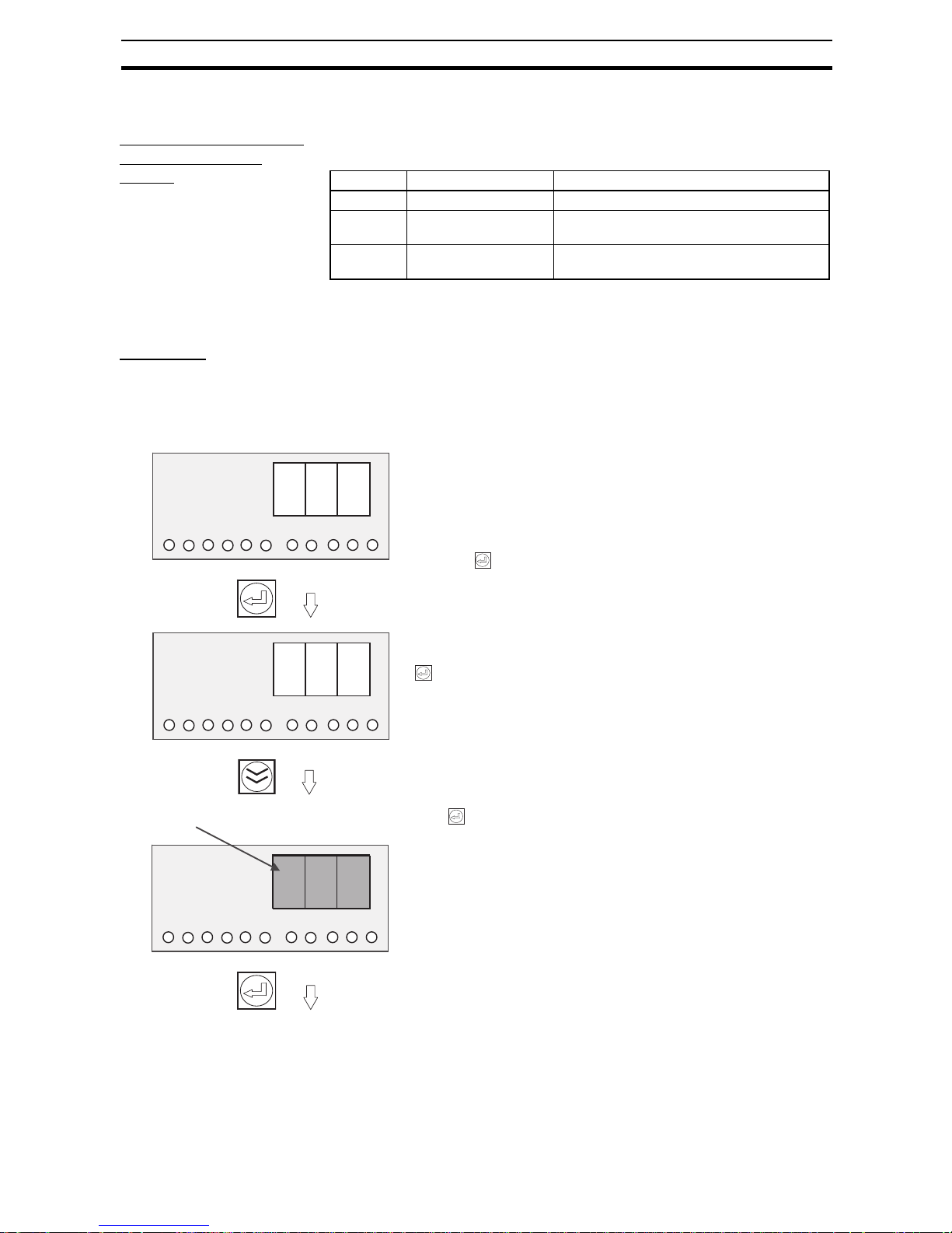
59
Changing the Protection Level Section 4-3
4-3 Changing the Protection Level
Operations Restricted
in the Protection
Levels
The protection level function can restrict parameter read/write access to one
of three levels, as shown in the following table. (Refer to 4-1 Parameter Table)
The default protection level is level 1. When the parameters are initialized, the
protection level is set to le vel 1.
Procedure The factory default protection level is level 1, so the protection level must be
changed in order to switch to level 0. Use the following procedure to change
the protection level.
Display the Mode Selection Menu and select the Protection Level setting
(PRT).
Level Applicable user Access
Level 0 System administrator All parameters can be read and changed.
Level 1 Supervisor Only operational settings related to voltage
and current can be read and changed.
Level 2 General staff A limited number of parameters can be read.
No parameters can be changed.
Press the Key.
LV1 (level 1) will be displayed.
The present protection level is level 1 (the default value), so press the
Key to change to level 0.
If the Key is pressed, the LV0 display will flash. When the display
stops flashing, the protection level will be switched to level 0 and the
S8AS will return to the Protection Level Setting (PRT).
(Returns to PRT.)
p r t
1
2
3
4
5
6
V
A
Yrs
s
°C
l V 1
1
2
3
4
5
6
V
A
Yrs
s
°C
Flashing
l 1
l V 0
1
2
3
4
5
6
V
A
Yrs
s
°C
Page 78

60
Switching to Setting Mode Section 4-4
4-4 Switching to Setting Mode
When the S8AS is started, it will enter Run Mode. If the power was turned
OFF while the S8AS was in Test Mode, it will star t in Test Mode the next time
it is started.
To switch to Setting Mode from Run Mode or Test Mode, select Setting Mode
from the Mode Selection Menu, as shown below.
The Mode Selection Menu can be displayed by pressing both the Up (SEL)
Key ( ) and Down (CH) Key ( ) simultaneously for 3 seconds.
Selecting the Operating Mode from the Mode Selection Menu
The initial Setting Mode display is the abnormal current tripping threshold (CV) for branch output 1.
The branch output that was most recently modified will be the current branch
output regardless of the operating mode.
Once the S8AS is switched to Setting Mode, it will not return to Run Mode
automatically.
(To return to Mode Selection Menu, press the and Keys simultaneously for 3 seconds again.)
For details on setting parameters in Setting Mode, refer to the following pages.
If the S8AS is switched to the Mode Selection Menu from Run Mode,
RUN (select Run Mode) will be displayed.
Press the Key.
When the
Key is pressed, SET (select Setting Mode) will be dis-
played.
If the Key is pressed, the S8AS will switch to Setting Mode.
The initial display for Setting Mode will be displayed.
r u n
1
2
3
4
5
6
V
A
Yrs
s
°C
s e t
1
2
3
4
5
6
V
A
Yrs
s
°C
Branch output number 1 is lit.
c - V
The "A" unit indicator will
be lit when a current is
displayed.
1
2
3
4
5
6
V
A
Yrs
s
°C
Page 79

61
Individual Branch Output Settings Section 4-5
4-5 Individual Branch Output Settings
This section shows the displays and operations when setting parameters in
Setting Mode in protection level 0. If the protection level is set to level 1 or 2,
some parameters will not be displayed or will be read-only. (For details, see
page 54.)
Setting the Abnormal Current Tripping Threshold: C-V (Cutoff Threshold Value)
The initial Setting Mode display (C-V) is used to set the abnormal current tripping threshold. (The branch output that was most recently modified will be the
current branch output regardless of the operating mode.)
Note If the branch output's current exceeds the threshold, the output will be cut off.
The current tripping type is set with the following C-T (cutoff type) display. The
tripping type can be set in protection level 0 only.
After an output is cut off, the sev en-segment display will alternately show error
code A11 and the current, and the photoswitch output for Tripping Alarm Output (TRP) will be turned OFF.
The error can be cleared immediately, but the next error cannot be cleared for
another 15 s.
When the Key is pressed, the SV display will flash. When the
flashing stops, the new SV will be saved and the S8AS will return to
C-V display.
If you want to confirm the new setting, press the Key again from
the C-V display.
c - V
1
2
3
4
5
6
V
A
Yrs
s
°C
c - V
1
2
3
4
5
6
V
A
Yrs
s
°C
(To change the
branch output)
# 8
1
2
3
4
5
6
V
A
Yrs
s
°C
Press the Key to display the set value of the
branch output 1 current tripping threshold.
The S8AS will automatically return to the C-V
display if no key is pressed within 3 s.
Switch to the current tripping type
setting (C-T).
B 5
1
2
3
4
5
6
V
A
Yrs
s
°C
The set value can be changed by pressing the or
Keys.
The setting range is 0.5 to 3.8 A (0.1-A increments).
• If the or Key is pressed for more than 2 s, the
SV will change in 1.0-A increments instead of 0.1-A
increments.
(
Returns to C-V display.
)
Page 80

62
Individual Branch Output Settings Section 4-5
Setting the Abnormal Current Tripping Type: C-T (Cutoff Type)
This parameter can be set in protection level 0 only.
Select the current tripping type for the displayed branch output number.
(The branch output that was most recently modified will be the current branch
output regardless of the operating mode.)
Press the Key to display the setting.
The setting can be changed by pressing the or Key.
The S8AS will automatically return to the C-T display if no
key is pressed within 3 s.
The setting can be changed by pressing the or Key.
When the Key is pressed, the SV display will flash.
When the flashing stops, the new SV will be saved and the
S8AS will return to C-T display.
If you want to confirm the new setting, press the Key
again from the C-T display.
c -
1
2
3
4
5
6
V
A
Yrs
s
°C
c -
1
2
3
4
5
6
V
A
Yrs
s
°C
t
t
(To change the
branch output)
u s u
1
2
3
4
5
6
V
A
Yrs
s
°C
USU (Standard):
USU is an abbreviation of “usually.”
The output will be cut off within 100 ms.
INS (Instantaneous):
INS is an abbreviation of “instantaneous.”
The output will be cut off within 20 ms.
LGN (Extended detection):
LNG is an abbreviation of “long.”
The output will be cut off within 1,000 ms.
Switch to the
Undervoltage Detection Output
setting (V-U).
i n s
1
2
3
4
5
6
V
A
Yrs
s
°C
l n g
1
2
3
4
5
6
V
A
Yrs
s
°C
(Returns to C-T display.)
Page 81

63
Shared Parameter Settings Section 4-6
4-6 Shared Parameter Settings
Setting the Undervoltage Detection Output Value: V-U (Voltage Under)
After setting the abnormal current tripping threshold and tripping type for all
branch outputs, press the Up (SEL) Key ( ) to go to the Undervoltage
Detection Threshold Display (V-U).
Note If the voltage remains below the detection threshold for 80 ms, the photo-
switch output for the Undervoltage Detection Output (LOW) will turn OFF. At
the same time, the seven-segment display will show the error code A21 and
the voltage val ue.
The alarm output can be cleared after the voltage rises above the threshold
+0.3 V for more than 500 ms.
Standard (usu) When the current exceeds the tripping threshold for more than 80
ms, the branch output is cut off and the Tripping Alarm Output (TRP)
is turned OFF. Th e output will be cut off within 100 ms.
Instantaneous (ins) When the current exceeds the tripping threshold for more than 10
ms, the branch output is cut off and the Tripping Alarm Output (TRP)
is turned OFF. Th e output will be cut off within 20 ms.
Extended (lng) When the current exceeds the tripping threshold for more than 980
ms, the branch output is cut off and the Tripping Alarm Output (TRP)
is turned OFF. Th e output will be cut off within 1,000 ms.
(Returns to V-U display.)
V - u
2 * 0
2 ! 5
1
2
3
4
5
6
V
A
Yrs
s
°C
1
2
3
4
5
6
V
A
Yrs
s
°C
1
2
3
4
5
6
V
A
Yrs
s
°C
This parameter sets the undervoltage detection threshold.
Press the Key to display the undervoltage detection's set value (SV).
The SV can be changed by pressing the and
Keys.
The setting range is 18.0 to 26.4 V (0.1-V increments).
• If the or Key is pressed for more than 2 s, the
SV will change in 1.0-V increments instead of 0.1-V
increments.
Change the SV with the and Keys.
The S8AS will automatically return to the V-U display if
no key is pressed within 3 s.
When the Key is pressed, the SV display will flash.
When the flashing stops, the new setting will be saved
and the S8AS will return to V-U display.
If you want to confirm the new setting, press the Key
again from the V-U display.
Switch to the
Maintenance
Forecast Monitor Detection
Threshold Setting (LFE).
Page 82

64
Shared Parameter Settings Section 4-6
Setting the Maintenance Forecast Monitor Detection Threshold: LFE (Life)
The Maintenance Forecast Monitor Detection Threshold Setting (LFE) will be
displayed if the Up (SEL) Key ( ) is pressed from the Undervoltage Detec-
tion Threshold Setting Display (V-U).
Note The maintenance forecast monitor output is an estimate of the lifetime of the
electrolytic capacitor in the power supply circuit. It is calculated from the
power-ON time and internal temperature. When the estimated lifetime falls
below the threshold value, the maintenance forecast monitor output (LFE)
photoswitch output will turn OFF, and the seven-segment display will alternately show error code A23 and the remaining lifetime (in 0.5-year increments).
(
Returns to LFE display.
)
l f e
* 5
! 0
1
2
3
4
5
6
V
A
Yrs
s
°C
1
2
3
4
5
6
V
A
Yrs
s
°C
1
2
3
4
5
6
V
A
Yrs
s
°C
This parameter sets the maintenance forecast monitor output.
Press the Key to display the set value (SV). The SV
can be changed by pressing the and Keys.
The setting range is 0 to 5 years, in 0.5-year increments.
• If the or Key is pressed for more than 2 s, the
SV will change in 1.0-V increments instead of 0.5-V
increments.
Change the SV with the and Keys.
The S8AS will automatically return to the LFE display if
no key is pressed within 3 s.
When the Key is pressed, the SV display will flash.
When the flashing stops, the new setting will be saved
and the S8AS will return to LFE display.
If you want to confirm the new setting, press the Key
again from the LFE display.
Switch to the
Over-temperature Output
Threshold Setting (TMP).
Page 83

65
Shared Parameter Settings Section 4-6
Setting the Over-temperature Output Threshold: TMP (Temperature)
The Over-Temperature Output Threshold Sett ing (TMP) will be displa y ed if t he
Up (SEL) Key ( ) is pressed from th e Ma in te na nce Forecast Monitor Detec-
tion Threshold Setting (LFE).
Note • If the temperature exceeds the threshold value for more than 1 s, the
over-temperature output (TMP) photosw itch output will turn OFF and the
seven-segment display will alternate between error code A30 and the
measured temperature.
• The error display and over-temperature output are reset automatically
after the temperature falls and remains below the threshold value minus
3°C for longer than 5 s.
• The over-temperature output (TMP) operates independently of the other
external outputs. This output can be received as a normally closed output
and used to start an exhaust fan or air conditioner to reduce the temperature in the control panel.
(
Returns to TMP display.
)
t m p
9 0
8 0
1
2
3
4
5
6
V
A
Yrs
s
°C
1
2
3
4
5
6
V
A
Yrs
s
°C
1
2
3
4
5
6
V
A
Yrs
s
°C
This parameter sets the over-temperature output threshold.
Press the Key to display the over-temperature output threshold (SV). The SV can be changed by press-
ing the and Keys.
The setting range is 25°C to 90°C
Change the SV with the and Keys.
•The S8AS will automatically return to the TMP display if no key is pressed within 3 s.
•If the or Key is pressed for more than 2 s, the
SV will change in 10°C increments instead of 1°C
increments.
When the Key is pressed, the SV display will flash.
When the flashing stops, the new setting will be saved
and the S8AS will return to TMP display.
If you want to confirm the new setting, press the
Key again from the TMP display.
Switch to the startup sequence setting (UPS).
Page 84

66
Special Settings and Communications Settings Section 4-7
4-7 Special Settings and Communications Settings
The Startup Sequence Setting (UPS) will be displayed if the S8AS is in protection level 0 and the Up (SEL) Key ( ) is pressed from the Over-Tempera-
ture Output Threshold Setting Display (TMP), which was described at the end
of 4-6 Shared Parameter Settings.
Setting the Startup Sequence: UPS (Startup Sequence)
The startup sequence sets the startup sequence time for each branch out put.
(The branch output that was most recently modified will be the current branch
output regardless of the operating mode.)
Note The startup sequence sets a delay before the S8AS connects the branch out-
put after the power is turned ON. Connecting the branch outputs in sequence
instead of simultaneously can reduce the inrush current and reduce the load
on the power supply. For details on the startup sequence, refer to 2-5 Startup
Sequence Function.
(Returns to UPS display.)
u p s
u p s
* 0
# 8
1
2
3
4
5
6
V
A
Yrs
s
°C
1
2
3
4
5
6
V
A
Yrs
s
°C
1
2
3
4
5
6
V
A
Yrs
s
°C
1
2
3
4
5
6
V
A
Yrs
s
°C
(To change the
branch output)
Press the Key to display the startup sequence time
set value (SV) for the current branch output. The SV can
be changed by pressing the and Keys. The setting range is 0.0 to 99.9 s (0.1-s increments).
Note If the or Key is pressed for more than 2 s,
the SV will change in 1.0-s increments instead of
0.1-s increments.
Change the SV with the and Keys.
The S8AS will automatically return to the UPS display if no
key is pressed within 3 s.
When the Key is pressed, the SV display will flash.
When the flashing stops, the new setting will be saved and
the S8AS will return to UPS display.
If you want to confirm the new setting, press the Key
again from the UPS display.
To change the startup sequence settings of other branch
outputs, press the Key from the UPS display to select
the desired branch output, and then follow the procedure to
change the settings.
Switch to the
Shutdown
Sequence
setting.
Page 85

67
Special Settings and Communications Settings Section 4-7
Setting the Shutdown Sequence: DWS (Shutdown Sequence)
The Shutdown Sequence Setting (DWS) will be displayed if the Up (SEL) Key
( ) is pressed from the Startup Sequence Setting Display. The shutdown
sequence sets the shutdown sequence time for each branch output. (The
branch output that was most recently modified will be the current branch output regardless of the operating mode.)
Note The shutdown sequence function sets the time that the S8AS waits before
cutting off each branch output when the branch outputs are cut off by the
external tripping input or communications. For details on the startup
sequence, refer to 2-6 Shutdown Sequence Function.
(Returns to DWS display.)
d w s
d w s
* 0
% 5
1
2
3
4
5
6
V
A
Yrs
s
°C
1
2
3
4
5
6
V
A
Yrs
s
°C
1
2
3
4
5
6
V
A
Yrs
s
°C
1
2
3
4
5
6
V
A
Yrs
s
°C
(To change the
branch output)
Press the Key to display the Shutdown Sequence
Time Set Value (SV) f or the current branch output. The SV
can be changed by pressing the and Keys. The
setting range is 0.0 to 99.9 s (0.1-s increments).
Change the SV with the and Keys.
The S8AS will automatically return to the DWS display if
no key is pressed within 3 s.
If the or Key is pressed for more than 2 s, the SV
will change in 1.0-s increments instead of 0.1-s incre-
ments.
When the Key is pressed, the SV display will flash.
When the flashing stops, the new setting will be saved and
the S8AS will return to DWS display.
• If you want to confirm the new setting, press the Key
again from the DWS display.
• To change the shutdown sequence of other branch out-
puts, press the Key from the DWS display to select
the desired branch output, and then follow the procedures
to change the settings.
Switch to the
Tripping Input
Trigger Setting
(TRG).
Page 86

68
Special Settings and Communications Settings Section 4-7
Tripping Input Trigger Setting: TRG (Trigger)
The Tripping Input Trigger Setting (TRG) will be displayed if the Up (SEL) Key
( ) is pressed from the Shutdown Sequence Setting Display.
The tripping input (TRG) can be enabled or disabled independently for each
branch output.
(The branch output that was most recently modified will be the current branch
output regardless of the operating mode.)
Note (1) If the Exter nal Tripping Input (TRG) is enabled for any branch outputs,
those outputs will be cut off within 20 ms when the TRG input is ON for
more than 10 ms.
(2) The shutdown delays specified by the shutdown sequence times will be
applied before disconnecting each output.
(3) When the TRG input goes ON, the seven-segment display will indicate
“TRG.”
(Returns to TRG display.)
t r g
t r g
o n
o f f
1
2
3
4
5
6
V
A
Yrs
s
°C
1
2
3
4
5
6
V
A
Yrs
s
°C
1
2
3
4
5
6
V
A
Yrs
s
°C
1
2
3
4
5
6
V
A
Yrs
s
°C
(To change the
branch output)
Press the Key to display the branch output parameter
settings.
The setting can be changed by pressing the or Key.
ON (enabled): The corresponding branch output will be
cut off when the TRG input is ON.
OFF (disabled): The TRG input has no effect on the corre-
sponding branch output.
Change the setting with the or Key.
• The S8AS will automatically return to the TRG display if no
key is pressed within 3 s.
When the Key is pressed, the SV display will flash.
When the flashing stops, the new setting will be saved and
the S8AS will return to TRG display.
•If you want to confirm the new setting, press the Key
again from the TRG display.
• To change the tripping input trigger setting of other branch
outputs, press the Key from the TRG display to select
the desired branch output, and then follow the procedure to
change the settings.
Switch to the
Tripping Input
Type Setting
(TGS).
Page 87

69
Special Settings and Communications Settings Section 4-7
(4) Once the TRG input goes OFF, the cut-off branch outputs can be recon-
nected by pressing the Reset Key.
(5) When all outputs are cut off simultaneously in Test mode or the shutdown
sequence operation is e xecuted via communications , t he br a nch out puts
will be cut off regardless of the external tripping input trigger setting.
Tripping Input Type: TGS (Trigger Sense)
The Tripping Input Condition Setting (TGS) will be displayed if the Up (SEL)
Key ( ) is pressed from the External Tr ipping Input Trigger Setting Display
(TRG).
(
Returns to TGS display.
)
t g s
e g e
l V l
1
2
3
4
5
6
V
A
Yrs
s
°C
1
2
3
4
5
6
V
A
Yrs
s
°C
1
2
3
4
5
6
V
A
Yrs
s
°C
Press the Key to display the tripping input type.
The setting can be changed by pressing the or Key .
EGE (Edge): Output is cut off when TRG input changes
from OFF to ON.
LVL (Level): Output is cut off when TRG input changes from
OFF to ON, and is connected when TRG
input changes from ON to OFF.
Change the setting with the or Key.
• The S8AS will automatically return to the TGS display if
no key is pressed within 3 s.
When the Key is pressed, the SV display will flash.
When the flashing stops, the new setting will be saved and
the S8AS will return to TGS display.
•If you want to confirm the new setting, press the Key
again from the TGS display.
This parameter sets the tripping input type for each branch output that has
tripping input (TRG) enabled.
Switch to the
Communications Unit No.
Setting (UNO)
for models
with communications. (See
note.)
Note: For models without communications,
switch to Reset
Method Setting
(page 76).
Page 88

70
Special Settings and Communications Settings Section 4-7
Unit Number Setting: UNO (Unit Number)
The Unit Number Setting (UNO) will be displayed if the Up (SEL) Key ( ) is
pressed from the External Tripping Input Type Display (TGS).
(Returns to UNO display.)
u n o
0
1
1
2
3
4
5
6
V
A
Yrs
s
°C
1
2
3
4
5
6
V
A
Yrs
s
°C
1
2
3
4
5
6
V
A
Yrs
s
°C
Set the S8AS's unit number when using 1:N communications with the host
computer.
Press the Key to display the unit number setting. The
setting can be changed by pressing the and Keys.
•If the or Key is pressed for more than 2 s, the SV
will change by 10s instead of 1s.
When the Key is pressed, the setting will flash. When the
flashing stops, the new setting will be saved and the S8AS
will return to UNO display.
•If you want to confirm the new setting, press the Key
again from the UNO display.
The setting range is 0 to 31.
Change the SV with the
and Keys.
•The S8AS will automatically return to the UNO display if no
key is pressed within 3 s.
Switch to the
Baud Rate
Setting
(BPS).
Page 89

71
Special Settings and Communications Settings Section 4-7
Baud Rate: BPS (Bits Per Second)
The Baud Rate Setting (BPS) will be displayed if the Up (SEL) Key ( ) is
pressed from the Unit Number Setting Display (UNO).
(Returns to BPS display.)
b p s
9 6
4 8
1
2
3
4
5
6
V
A
Yrs
s
°C
1
2
3
4
5
6
V
A
Yrs
s
°C
1
2
3
4
5
6
V
A
Yrs
s
°C
Press the Key to display the baud rate setting. The set
-
ting can be changed by pressing the or Key.
96: 9,600 bps
48: 4,800 bps
Change the setting with the or Key.
•The S8AS will automatically return to the BPS display if
no key is pressed within 3 s.
When the Key is pressed, the setting will flash. When
the flashing stops, the new setting will be saved and the
S8AS will return to the “BPS” display.
If you want to confirm the new setting, press the Key
again from the BPS display.
Switch to the
data length
setting (LEN).
This parameter sets the RS485 port's baud rate to 4,800 bps or 9,600 bps.
Page 90

72
Special Settings and Communications Settings Section 4-7
Data Length: LEN (Bit Length)
The Data Length Setting (LEN) will be displayed if the Up (SEL) Key ( ) is
pressed from the Baud Rate Setting Display (BPS).
(Returns to LEN display.)
l e n
7
8
1
2
3
4
5
6
V
A
Yrs
s
°C
1
2
3
4
5
6
V
A
Yrs
s
°C
1
2
3
4
5
6
V
A
Yrs
s
°C
This parameter sets the data length to 7 or 8 bits.
Press the Key to display the data length setting.
The setting can be changed by pressing the or Key.
7: 7 bits
8: 8 bits
Change the setting with the or Key.
• The S8AS will automatically return to the LEN display if
no key is pressed within 3 s.
When the Key is pressed, the setting will flash. When
the flashing stops, the new setting will be saved and the
S8AS will return to the LEN display.
•If you want to confirm the new setting, press the Key
again from the LEN display.
Switch to the
Stop Bits Setting (BIT).
Page 91
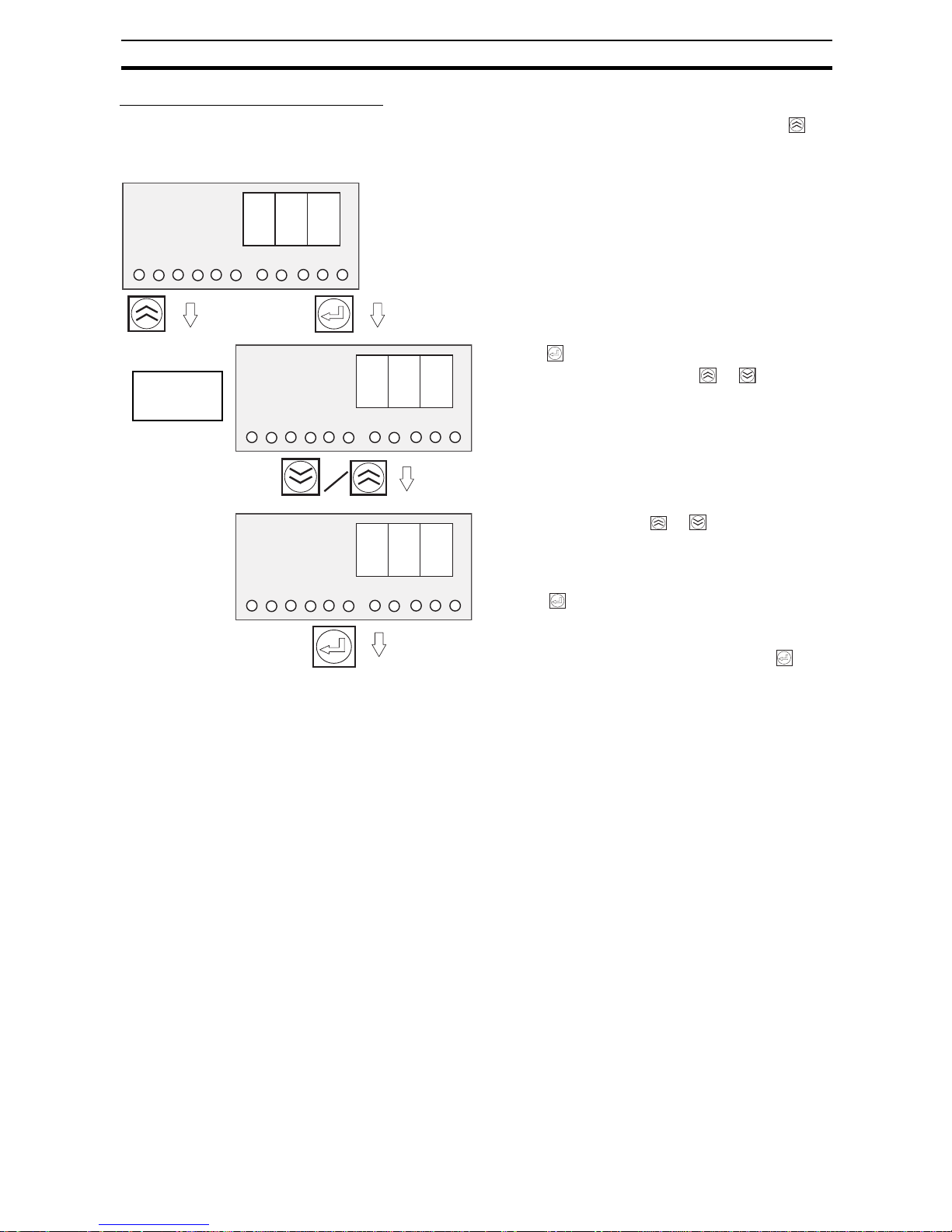
73
Special Settings and Communications Settings Section 4-7
Stop Bit Setting: BIT (Stop Bits)
The Stop Bit Setting (BIT) will be displayed if the Up (SEL) Key ( ) is
pressed from the Data Length Setting Display (LEN).
(Returns to BIT display.)
b i t
2
1
1
2
3
4
5
6
V
A
Yrs
s
°C
1
2
3
4
5
6
V
A
Yrs
s
°C
1
2
3
4
5
6
V
A
Yrs
s
°C
This parameter sets the number of stop bits to 1 bit or 2 bits.
Press the Key to display the stop bit setting. The setting can be changed by pressing the or Key.
1: 1 bit
2: 2 bits
Change the setting with the or Key.
• The S8AS will automatically return to the “BIT” display if
no key is pressed within 3 s.
When the Key is pressed, the setting will flash. When
the flashing stops, the new setting will be saved and the
S8AS will return to the “BIT” display.
•If you want to confirm the new setting, press the Key
again from the “BIT” display.
Switch to the
Parity Setting
(PTY).
Page 92

74
Special Settings and Communications Settings Section 4-7
Parity Setting: PTY (Parity Bit)
The Parity Setting (PTY) will be displayed if the Up (SEL) Key ( ) is pressed
from the Stop Bit Setting Display (BIT).
(Returns to PTY display.)
p t y
e V n
o d d
n o n
1
2
3
4
5
6
V
A
Yrs
s
°C
1
2
3
4
5
6
V
A
Yrs
s
°C
1
2
3
4
5
6
V
A
Yrs
s
°C
1
2
3
4
5
6
V
A
Yrs
s
°C
This parameter sets the parity to none, even, or odd.
Press the Key to display the parity setting.
The setting can be changed by pressing the and
Keys.
Evn: Even
odd: Odd
non: None
Change the setting with the or Key.
• The S8AS will automatically return to the TMP display if no key is pressed within 3 s.
Change the setting with the or Key.
When the Key is pressed, the setting will flash.
When the flashing stops, the new setting will be saved
and the S8AS will return to the PTY display.
If you want to confirm the new setting, press the
Key again from the PTY display.
Switch to the
Send Wait
Time Setting
(SWT).
Page 93

75
Special Settings and Communications Settings Section 4-7
Send Wait Time: SWT (Send Wait Time)
The Send Wait Time Setting (SWT) will be displayed if the Up (SEL) Key ( )
is pressed from the Parity Setting Display (PTY).
(Returns to SWT display.)
s w t
0
1 0
1
2
3
4
5
6
V
A
Yrs
s
°C
1
2
3
4
5
6
V
A
Yrs
s
°C
1
2
3
4
5
6
V
A
Yrs
s
°C
This parameter sets the RS-485 port's send wait time.
Press the Key to display the send wait time setting.
The setting can be changed by pressing the and
Keys.
The setting range is 0 to 999 ms.
Change the setting with the and Keys.
• If the or Key is pressed for more than 2 s, the SV
will change in 10-ms increments instead of 1-ms incre-
ments.
• The S8AS will automatically return to the SWT display if
no key is pressed within 3 s.
When the Key is pressed, the setting will flash. When
the flashing stops, the new setting will be saved and the
S8AS will return to SWT display.
•If you want to confirm the new setting, press the Key
again from the SWT display.
Switch to the
Reset
Method Setting (RST).
Page 94

76
Special Settings and Communications Settings Section 4-7
Reset Method Setting: RST (Reset)
The error resetting method can be set. This method will be used to reset
errors after eliminating the cause of the error.
(Returns to RST display.)
r s t
k e y
a l l
1
2
3
4
5
6
V
A
Yrs
s
°C
1
2
3
4
5
6
V
A
Yrs
s
°C
1
2
3
4
5
6
V
A
Yrs
s
°C
Press the Key to display the send wait time setting.
The setting can be changed by pressing the or
Key.
KEY: Errors can be reset using the S8AS Reset Key only.
ALL: Errors can be reset using the S8AS Reset Key or by
turning the power supply OFF.
Change the setting with the or Key.
• The S8AS will automatically return to the RST display if
no key is pressed within 3 s.
When the Key is pressed, the setting will flash.
When the flashing stops, the new setting will be saved and
the S8AS will return to the RST display.
Switch to the
Abnormal Current Tripping
Threshold Setting (C-V).
This parameter sets the error reset method.
Page 95

77
SECTION 5
Trial Operation to Actual Operation
A connection/disconnection test can be performed on each branch output in Test Mode.
When the S8AS is shipped from the factory, all branch outputs are connected.
If you want to set unused branch outputs so that they are not connected, set those outputs to OFF in Test Mode.
5-1 Test Mode . . . . . . . . . . . . . . . . . . . . . . . . . . . . . . . . . . . . . . . . . . . . . . . . . . . . 78
5-2 Connection/Disconnection Test . . . . . . . . . . . . . . . . . . . . . . . . . . . . . . . . . . . 80
5-3 Checking Sequence Operation . . . . . . . . . . . . . . . . . . . . . . . . . . . . . . . . . . . . 81
5-4 Run Mode . . . . . . . . . . . . . . . . . . . . . . . . . . . . . . . . . . . . . . . . . . . . . . . . . . . . 82
Page 96

78
Test Mode Section 5-1
5-1 Test Mode
Each branch output's connection status can be checked and the outputs can
be connected manually in Test Mode before starting actual operation of the
equipment.
The S8AS must be set to protection level 0 or 1 in order to switch to Test
Mode. (It is not possible to switch to Test Mode when the S8AS is set to protection level 2.)
Precautions when
Checking Operation
Before checking operation in Test Mode, always confirm that it is safe to do so
and will not adversely affect the system.
Setting the Branch
Outputs That Will Be
Used
The S8AS is a power supply unit. When it is shipped from the factory, all
branch outputs are set to “ON” (connected). After setting the parameters in
Setting Mode, change the connection status as required and then check
them.
Errors Occurring
During the
Connection Test
When an error occurs in Test Mode or the external tripping input is turned ON,
the tripping operation will be executed and the appropriate external output will
be turned OFF, but the error code will not be displayed.
When the S8AS is switched to Run Mode, the error code will be displayed.
In Test Mode, the abnormal tripping output (TRP) will operate if one or more of
the branch outputs are not connected. (The photoswitch outputs will turn
OFF.) No error code will be output. This type of TRP output is unique to the
Test Mode and will not be retained if the operating mode is changed.
Switching to Test
Mode
Press the Key and the Key together for at least 3 s to switch to the
Mode Selection Menu and select Test Mode.
Once the S8AS has been switched to Run Mode, it will start in either Run
Mode or Test Mode (see note) the next time that the power is turned ON, so
press the and the Keys together for at least 3 s to switch to the Mode
Selection Menu.
Note When the S8AS is tur ned OFF in Test Mode, it will restart in Test
Mode.
Page 97

79
Test Mode Section 5-1
Operations and Displays in the Mode Selection Menu
If the S8AS is switched to the Mode Selection Menu from Run
Mode, RUN will be displayed on the seven-segment display. If the
S8AS is switched to the Mode Selection Menu from Setting Mode,
SET will be displayed on the seven-segment display.
If the Key is pressed, SET will be displayed. At this point, the
S8AS will switch to Setting Mode if the Key is pressed.
• You cannot switch to Setting Mode if using models that do not
allow changes to settings (S8AS-24006N/48008N).
If the Key is pressed, TST will be displayed. At this point, the
S8AS will switch to Test Mode if the Key is pressed.
Press the Key to change to Test Mode.
The flashing “OFF” display indicates that the S8AS is ready to disconnect branch output 1.
Pressing the Key at this point will disconnect branch output 1.
r u n
23
4
°C
Yrs
V
A
s
1 5
6
s e t
23
4
°C
Yrs
V
A
s
1 5
6
t s t
23
4
°C
Yrs
V
A
s
1 5
6
1 2 3 4 5 6
f
o
f
23
4
°C
Yrs
V
A
s
1 5
6
Flashing
Page 98

80
Connection/Disconnection Test Section 5-2
5-2 Connection/Disconnection Test
Before performing the connection/disconnection test in Test Mode, always
confirm that it is safe to do so and will not adversely affect the system.
Use the above procedure to test connecting and disconnecting the branch
outputs and set the branch outputs that ar e to be used to “ON.”
Note Be sure to set the branch outputs that will be us ed to “ON.” If a
branch output is not set to “ON” when the S8AS is switched to Run
Mode, that branch output cannot be used.
If the Key is pressed a second time when testing the branch outputs, the
indictors for all branch outputs will flash and all branch outputs can be connected and disconnected at the same time.
To move to another mode after testing the branch outputs, press both the
Key and Key together for at least 3 seconds to switch to the Mode Selec-
tion Menu.
The flashing “OFF” display indicates that the S8AS is ready to
disconnect branch output 1.
To disconnect branch output 1, press the Key.
If the Key is pressed, branch output 1 will be disconnected
and the output 1 indicator will go OFF. The seven-segment display will flash the “ON” to indicate that the S8AS is ready to connect branch output1.
If the Key is pressed again, branch output 1 will be connected.
To test another branch output, press the Key to change the
branch output.
If the Key is pressed, the branch output 2 indicator will begin
to flash, indicating that the S8AS is ready to disconnect branch
output 2.
To disconnect branch output 2, press the Key.
Flashing
off
1 2 3 4 5 6
23
4
°C
Yrs
V
A
s
1 5
6
All of the branch output status indicators will be lit.
Flashing
The status indicator of branch output 1 will go OFF.
1 2 3 4 5 6
o
n
23
4
°C
Yrs
V
A
s
1 5
6
Flashing
o f f
1 2 3 4 5 6
23
4
°C
Yrs
V
A
s
1 5
6
Page 99

81
Checking Sequence Operation Section 5-3
5-3 Checking Sequence Operation
When you want to check the operation of the startup sequence function or
shutdown sequence function, press Key until all of the branch output indi-
cators are flashing.
To return to Run Mode after completing the test, press the Key and the
Key simultaneously for at least 3 s. The display will return to the Mode Selection Menu's TST display. Specify the next operation mode.
If the S8AS is turned OFF in Test Mode, it will restart in Test Mode the next
time that the power is turned ON. All branch outputs will retain the connection
status when power is OFF.
Press the Key while testing individual branch outputs
until all branch output indicators start flashing.
At this point, the operation all branch inputs can be
checked simultaneously. When the “OFF” display is flashing, it indicates that the S8AS is ready to simultaneously
disconnect all of the branch outputs.
If the Key is pressed, the S8AS starts cutting off all the
branch outputs, and the outputs will be cut off in the pattern specified in the shutdown sequence if the shutdown
sequence has been set.
When checking the startup sequences operation, press
the
Key to switch to the flashing “ON” display.
If the Key is pressed, the S8AS starts connecting all
the branch outputs, and the outputs will be connected in
the pattern specified in the startup sequence if the startup
sequence has been set.
The indicators for the branch outputs that are ready to be
connected will flash green.
Flashing
1 2 3 4 5 6
o f
f
23
4
°C
Yrs
V
A
s
1 5
6
The green indicator is lit.
(In this example, all of the branch outputs are connected.)
Flashing
OFF (In this example, all of the branch outputs are disconnected.)
1 2 3 4 5 6
o f f
23
4
°C
Yrs
V
A
s
1 5
6
Flashing
The indicators light green in the order of the connection sequence.
1 2 3 4 5 6
o n
23
4
°C
Yrs
V
A
s
1 5
6
Page 100

82
Run Mode Section 5-4
5-4 Run Mode
Switch to Run Mode after making connection settings and te stin g op eratio n in
Test Mode. In Run Mode, the outp ut voltage, present currents for branch outputs, peak output currents for branch outputs, total current, maintenance forecast monitor output, and internal temperature can be displayed. The peak
output currents can also be cleared.
Moving from Test Mode to Run Mode
Press the Key and the Key simultaneously for at least 3 s. The
display will return to the Mode Selection Menu.
Press the Key while “RUN” is being displayed to move to Run
Mode.
+
t s t
23
4
°C
Yrs
V
A
s
1 5
6
p r t
23
4
°C
Yrs
V
A
s
1 5
6
i n i
23
4
°C
Yrs
V
A
s
1 5
6
r u n
23
4
°C
Yrs
V
A
s
1 5
6
 Loading...