

Omron S82J DATASHEET
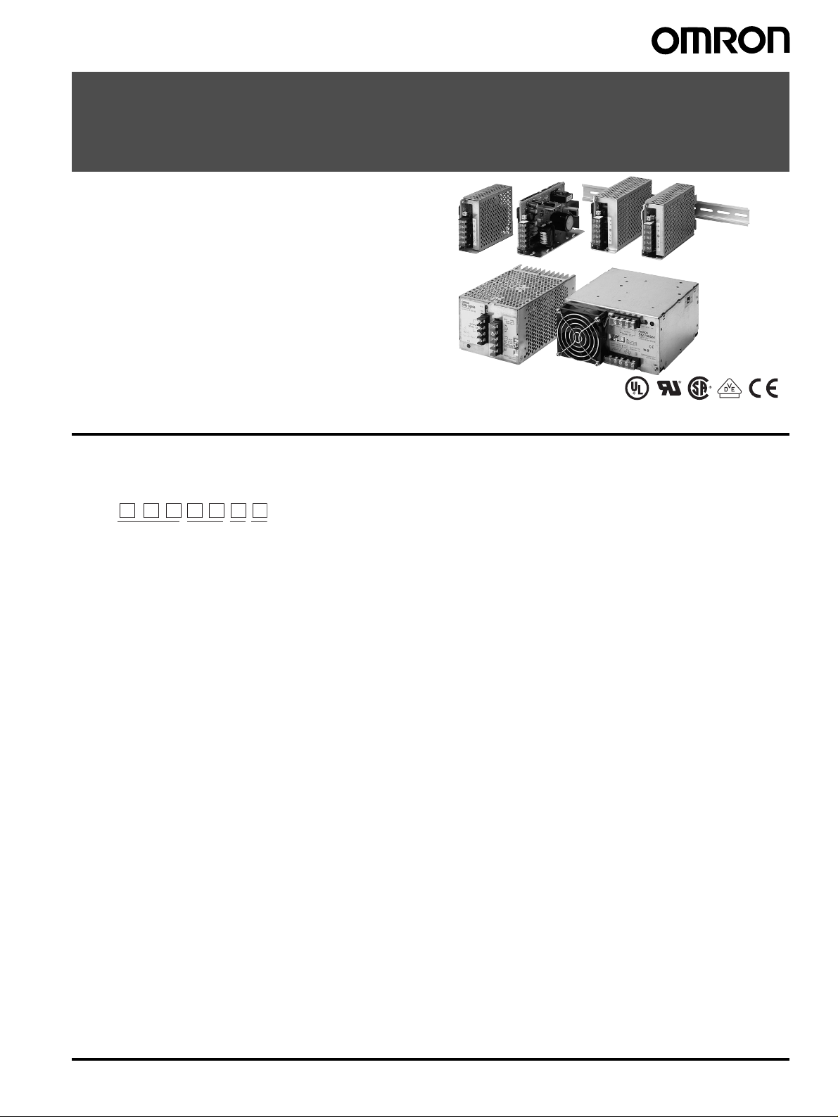
Switch Mode Power Supply
S82J (10/25/50/100/150/300/600-W Models)
Low-cost Global Power Supply with CE
Marking
• Safety standards:
UL: UL508, No.60950-1 Class 2,
CSA: cUL: C22.2 No. 14, cUR: 60950-1 Class 2,
EN60950-1 (=VDE0805 Teil 1), EN50178 (=VDE0160)
• EMC: Conforms to EN61204-3 Class A
• Mounting bracket available for standard models
Front-mounting bracket type
DIN Rail mounting type (except 300 W and 600 W)
Note: Refer to Precautions for Safe Use on page 17.
Model Number Structure
■ Model Number Legend
Note: Not all combinations are possible. Please refer to the list of models in Ordering Information on pages 2 and 3.
S82J -
1 32 4
1. Power Ratings
010: 10 W
025: 25 W
050: 50 W
100: 100 W
150: 150 W
300: 300 W
600: 600 W
3. Configuration
10-/25-/50-/100-/150-W models
A: Open-frame type, front terminals
D: Covered type, front terminals
Mounting bracket
None: With mounting bracket
N: Without mounting bracket
4. Mounting Bracket
None: Front-mounting bracket type
D: DIN Rail mounting bracket type
2. Output Voltage
05: 5 V
12: 12 V
15: 15 V
24: 24 V
Switch Mode Power Supply S82J 1
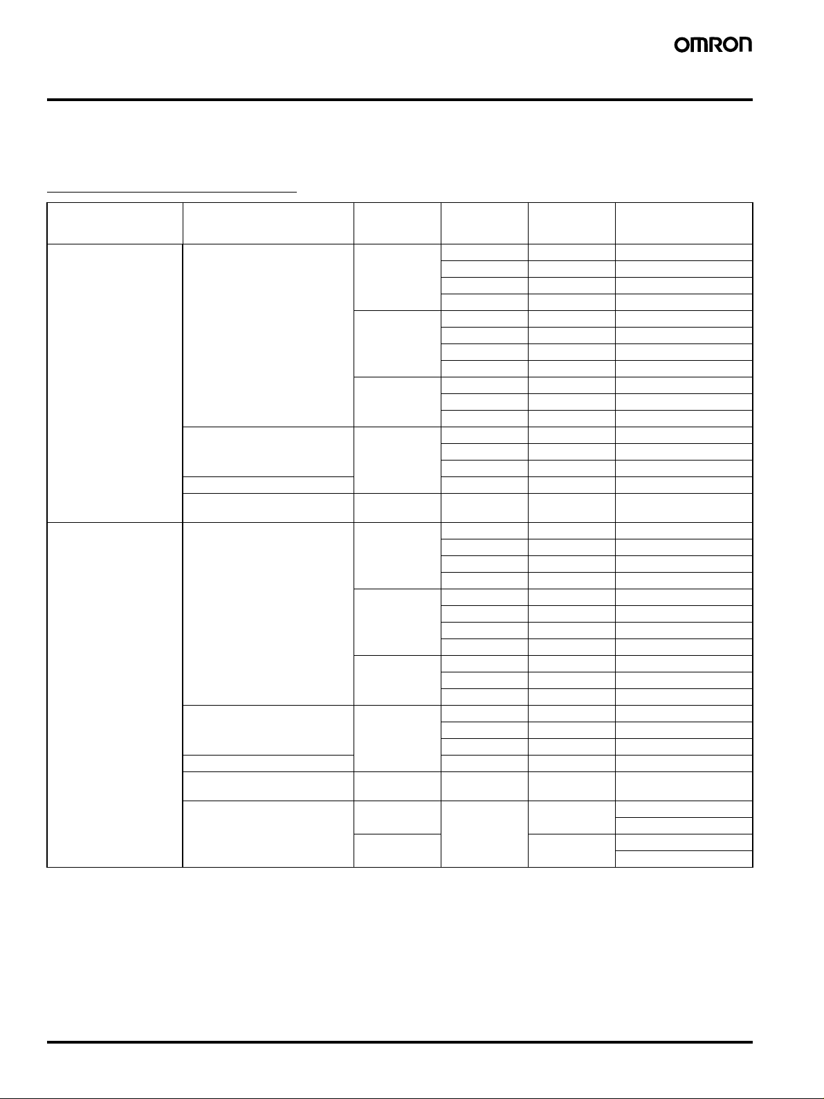
Ordering Information
■ List of Models
Note: For details on normal stock models, contact your nearest OMRON representative.
Front-mounting Bracket Type
Configuration Input Voltage Power ratings Output voltage Output current Front-mounting bracket
Open-frame type 100 to 240 VAC (free) 10 W 5 V 2 A S82J-01005A
12 V 1 A S82J-01012A
15 V 0.7 A S82J-01015A
24 V 0.5 A S82J-01024A
25 W 5 V 5 A S82J-02505A
12 V 2.1 A S82J-02512A
15 V 1.7 A S82J-02515A
24 V 1.1 A S82J-02524A
50 W 5 V 10 A S82J-05005A
12 V 4.2 A S82J-05012A
24 V 2.1 A S82J-05024A
100 or 200 VAC
(selected automatically)
100 to 240 VAC (free) 24 V 4.5 A S82J-10024A
100 or 200 VAC
(selected automatically)
Covered type 100 to 240 VAC (free) 10 W 5 V 2 A S82J-01005D
100 or 200 VAC
(selected automatically)
100 to 240 VAC (free) 24 V 4.5 A S82J-10024D
100 or 200 VAC (selected
automatically)
100 or 200 VAC (selectable) 300 W 24 V 14 A S82J-30024
100 W 5 V 20 A S82J-10005A
12 V 8.5 A S82J-10012A
15 V 7 A S82J-10015A
150 W 24 V 6.5 A S82J-15024A
12 V 1 A S82J-01012D
15 V 0.7 A S82J-01015D
24 V 0.5 A S82J-01024D
25 W 5 V 5 A S82J-02505D
12 V 2.1 A S82J-02512D
15 V 1.7 A S82J-02515D
24 V 1.1 A S82J-02524D
50 W 5 V 10 A S82J-05005D
12 V 4.2 A S82J-05012D
24 V 2.1 A S82J-05024D
100 W 5 V 20 A S82J-10005D
12 V 8.5 A S82J-10012D
15 V 7 A S82J-10015D
150 W 24 V 6.5 A S82J-15024D
S82J-30024N
600 W 27 A S82J-60024
S82J-60024N
types
(Front terminals)
2 Switch Mode Power Supply S82J
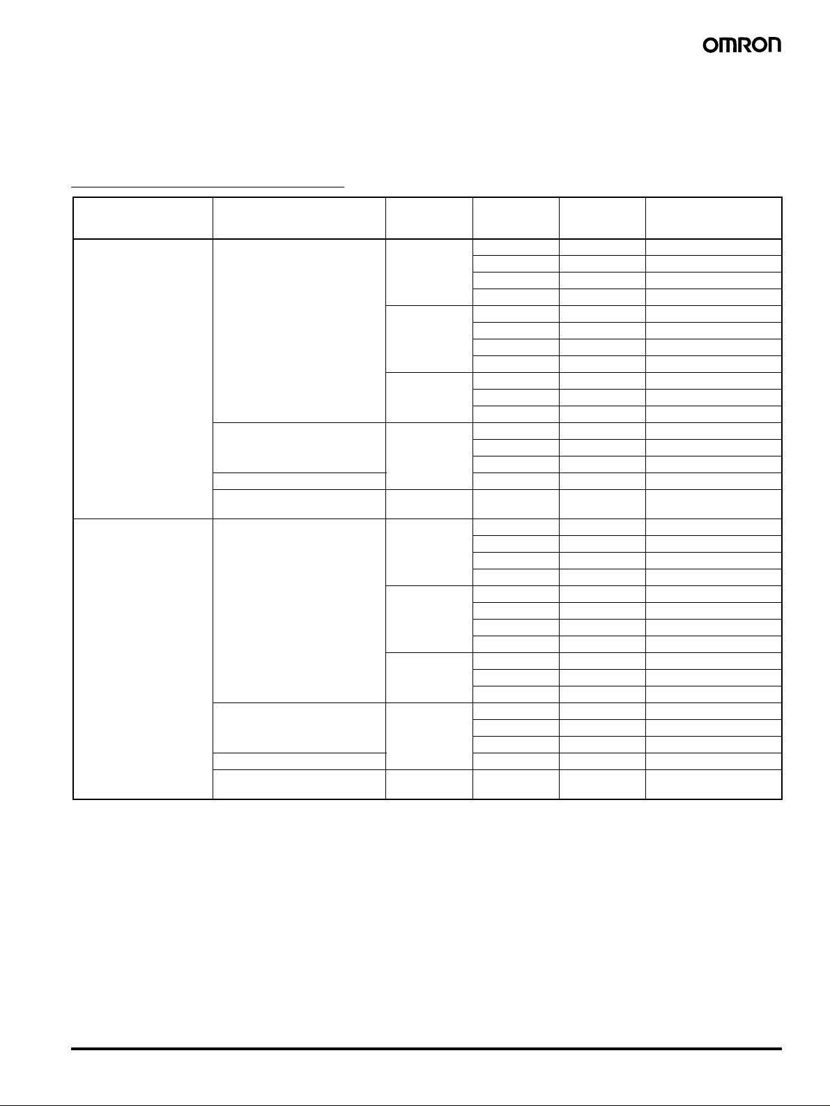
DIN Rail Mounting Bracket Type
Configuration Input Voltage Power ratings Output voltage Output current DIN Rail mounting
Open-frame type 100 to 240 VAC (free) 10 W 5 V 2 A S82J-01005AD
12 V 1 A S82J-01012AD
15 V 0.7 A S82J-01015AD
24 V 0.5 A S82J-01024AD
25 W 5 V 5 A S82J-02505AD
12 V 2.1 A S82J-02512AD
15 V 1.7 A S82J-02515AD
24 V 1.1 A S82J-02524AD
50 W 5 V 10 A S82J-05005AD
12 V 4.2 A S82J-05012AD
24 V 2.1 A S82J-05024AD
100 or 200 VAC
(selected automatically)
100 to 240 VAC (free) 24 V 4.5 A S82J-10024AD
100 or 200 VAC
(selected automatically)
Covered type 100 to 240 VAC (free) 10 W 5 V 2 A S82J-01005DD
100 or 200 VAC
(selected automatically)
100 to 240 VAC (free) 24 V 4.5 A S82J-10024DD
100 or 200 VAC
(selected automatically)
100 W 5 V 20 A S82J-10005AD
12 V 8.5 A S82J-10012AD
15 V 7 A S82J-10015AD
150 W 24 V 6.5 A S82J-15024AD
12 V 1 A S82J-01012DD
15 V 0.7 A S82J-01015DD
24 V 0.5 A S82J-01024DD
25 W 5 V 5 A S82J-02505DD
12 V 2.1 A S82J-02512DD
15 V 1.7 A S82J-02515DD
24 V 1.1 A S82J-02524DD
50 W 5 V 10 A S82J-05005DD
12 V 4.2 A S82J-05012DD
24 V 2.1 A S82J-05024DD
100 W 5 V 20 A S82J-10005DD
12 V 8.5 A S82J-10012DD
15 V 7 A S82J-10015DD
150 W 24 V 6.5 A S82J-15024DD
bracket types
(Front terminals)
Switch Mode Power Supply S82J 3
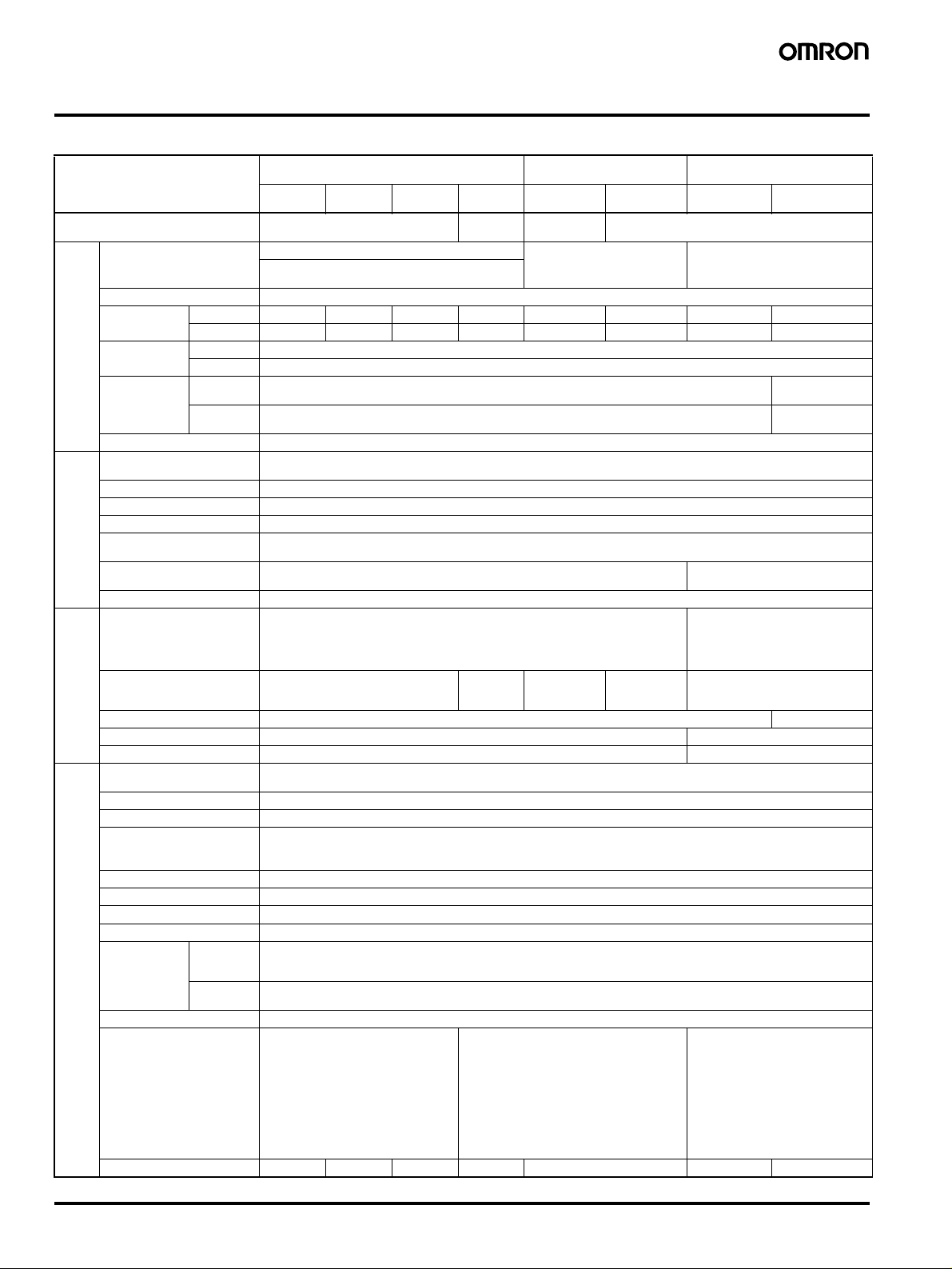
Specifications
■ Ratings/Characteristics
Power ratings
(See note 1.)
10 W 25 W 50 W 100 W
Efficiency (typical) 67% min. (Varies depending on
specifications)
Input Voltage (See note 2.) 100 to 240 VAC (85 to 264 VAC) 100 VAC (85 to 132 VAC)
110 to 170 VDC (10-W and 25-W models only) (See
note 11.)
100 to 240 V (Free) 100/200 (Selected
(24 V)
automatically)
100 W (5 V,
12 V, 15 V)
150 W 300 W 600 W
83% min. 75% min. 82% min.
200 VAC (170 to 264 VAC)
(selected automatically)
100/200 (Selected)
100 VAC (85 to 132 VAC)
200 VAC (170 to 253 VAC)
(selectable)
Frequency (See note 2.) 50/60 Hz (47 to 450 Hz)
Current
(See note 3.)
Leakage current
(See note 3.)
Inrush current
(See note 3.)
100-V input 0.35 A max. 0.8 max. 1.4 A max. 2.5 A max. 2.5 A max. 3.5 A max. 8 A max. 14 A max.
200-V input 0.3 A max. 0.6 A max. 0.8 A max. 1.5 A max. 1.4 A max. 2.1 A max. 4 A max. 7 A max.
100-V input 0.5 mA max.
200-V input 1 mA max.
100-V input 25 A max. (for cold start at 25
200-V input 50 A max. (for cold start at 25
°) 30 A max. (for cold
°) 60 A max. (for cold
Noise filter Yes
Output
Voltage Adjustment Range
(See note 5.)
(See
note 4.)
Ripple (See note 3.) 2% (p-p) max.
±10% (with V. ADJ)
Input variation influence 0.4% max.
Load variation influence 0.8% max. (10% to 100% load, rated input voltage)
Temperature variation
influence
Start up time 500 ms max. (up to 90% of output voltage at rated input and output) 300 ms max. (up to 90% of output
0.05%/
° max. (at rated input and output)
voltage at rated input and output)
Hold time (See note 3.) 20 ms min.
Addi-
Overload protection (See note
tional
6.)
functions
Overvoltage protection No Yes (See
105% to 160% of rated load current, voltage/current drop, intermittent operation (10-W
and 25-W models) gradual current increase/ voltage drop, intermittent operation (50W, 100-W (24 V) models), automatic reset
note 7.)
Yes (5-V output
only) (See note
7.)
No Yes (See note 8.)
105% of rated load current, Inverted
L voltage drop, automatic reset (For
the 600-W model, the circuit will be
shut OFF when the overload
exceeds 5 s.)
Overheat protection No Yes (See note 8.)
Parallel operation No Yes (up to 5 units)
Protection-ON alarm indicator No Yes (color: red)
Other Operating ambient
temperature
Storage temperature
Refer to the derating curve in Engineering Data. (with no icing or condensation)
−25 to 65°C (with no icing or condensation)
Operating ambient humidity 25% to 85% (Storage humidity: 25% to 90%)
Dielectric strength 3.0 k VAC for 1 min. (between all inputs and all outputs)
2.2 k VAC for 1 min. (between all inputs and all outputs/PE terminals)
1.0 k VAC for 1 min. (between all outputs and all PE terminals)
Insulation resistance 100 M
Ω min. (between all outputs and all inputs/ PE terminals) at 500 VDC
Vibration resistance 10 to 55 Hz, 0.375-mm single amplitude for 2h each in X, Y, and Z directions
Shock resistance
2
300m/s
, 3 times each in ±X, ±Y, ±Z directions
Output indicator Yes (color: green)
EMI Conducted
Emissions
(See note 3.)
Radiated
Emissions
Conforms to EN61204-3 EN55011 Class A and based on FCC Class A
Conforms to EN61204-3 EN55011 Class A (See note. 9)
EMS Conforms to EN61204-3 Low severity levels
Approved standards
UL: UL508 (Listing, Class 2), No. 60950-1
(Class 2 approved for 10-W, 25-W (except for
5-V output), and 50-W (only for 24-V output)
models.)
CSA: cUL: C22.2 No.14 (Class 2), cUR: No.
60950-1 (Class 2 approved for 10-W, 25-W
(except for 5-V output), and 50-W (only for 24V output) models.)
EN/VDE: EN50178 (VDE0160), EN60950-1
(VDE0805 Teil 1)
Terminal ty pes (onl y term inal par t):
VDE0106/P100
Based on VE0106/P100
UL: UL 508 (Listing), 1012, 60950-1
CSA: cUL: C22.2 No. 14, cUR: No. 60950-1
EN/VDE: EN50178 (VDE0160), EN60950-1
(VDE0805 Teil 1)
Terminal types (only terminal part):
VDE0106/P100
Based on VE0106/P100
UL: UL 508 (Listing), 1012, 60950-1
CSA: cUL: C22.2 No. 14, cUR: No. 609501
EN/VDE: EN50178 (VDE0160),
EN60950-1 (VDE0805 Teil 1)
Ter min al t yp es ( on ly t er min al p ar t) :
VDE0106/P100
Based on VE0106/P100
Weight 250 g max. 350 g max. 400 g max. 500 g max. 1,000 g max. 2,000 g max. 2,500 g max.
start at 25
start at 25
°)
°)
4 Switch Mode Power Supply S82J
Note: 1. When a load is connected that has a built-in DC-DC converter, the overload protection may operate at startup and the power supply may
not start.
Refer to the Overload Protection section on page 10 for details.
2. Do not use the Inverter output for the Power Supply. Inverters with an output frequency of 50/60 Hz are available, but the rise in the
internal temperature of the Power Supply may result in ignition or burning.
3. Defined with a 100% load and the rated input voltage (100 or 200 VAC.)
4. The output specification is defined at the Power Supply output terminals.
5. If the V. ADJ adjuster is turned the voltage will increase by more than +10% of the voltage adjustment range.
When adjusting the output voltage, confirm the actual output voltage from the Power Supply and be sure that the load is not damaged.
6. Refer to the Overload Protection section on page 10 for details.
7. For resetting, turn OFF the power, leave for more than one minute, and then turn it ON again.
8. The protection-ON alarm indicator will light as soon as the output is interrupted. For resetting, turn OFF the input power, leave for more
than three minutes (90 seconds min. for the 300-W models), and then turn it back ON again.
9. Radiated emissions: The noise value is affected by factors such as the wiring method. For 300-W and 600-W models, use shielded wire
for all wiring, and insert one noise clamp filter (TDK, ZCAT3035-1330) on the input wire, and two noise clamp filters on the load wire.
10.The weight indicated is the weight of the open-frame type. (Includes the covers for 300-W and 600-W models)
11.Use with DC voltage input is beyond the conditions of approval or conformance to applicable safety standards.
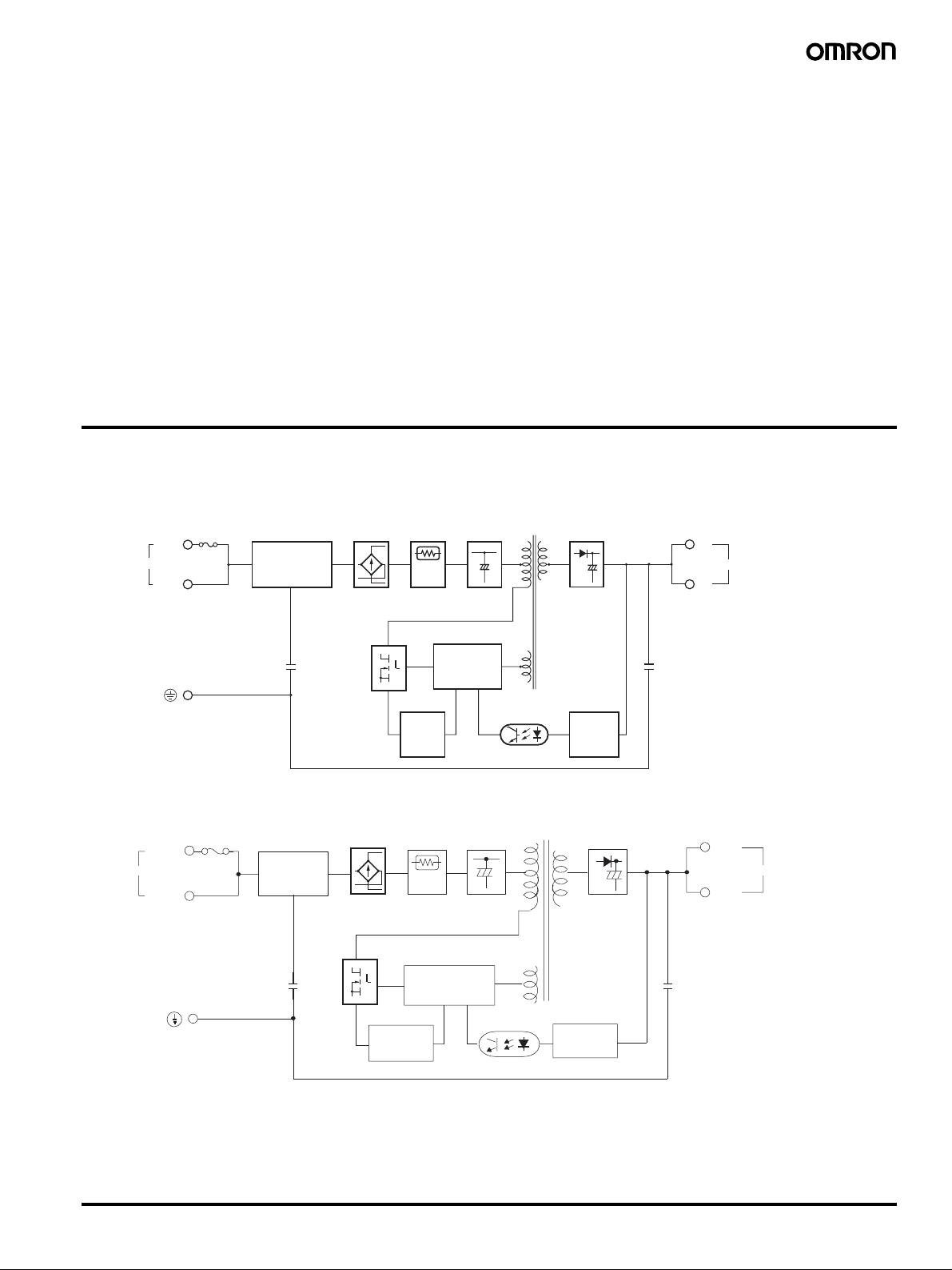
Connections
■ Block Diagrams
S82J-010@@@@ (10 W)
S82J-025@@@@ (25 W)
Fuse*
AC (L)
Input
AC (N)
* Fuse capacity: 10 W, 1 A
25 W, 2 A
Noise filter
Noise filter
Rectification
Inrush current
protection circuit
Smoothing
circuit
Rectification
and
smoothing
circuit
+V
DC Output
−
V
S82J-050@@@@ (50 W)
AC(L)
Input
AC(N)
* Fuse capacity: 3 A
Fuse*
Noise filter
Rectification
Overcurrent
detection
circuit
Control circuit
Overcurrent detection
circuit
Inrush current
protection
circuit
Control circuit
Photocoupler
Smoothing
circuit
Photocoupler
Detection
circuit
Rectification
and
smoothing
circuit
Detection
circuit
+V
DC Output
−V
Switch Mode Power Supply S82J 5
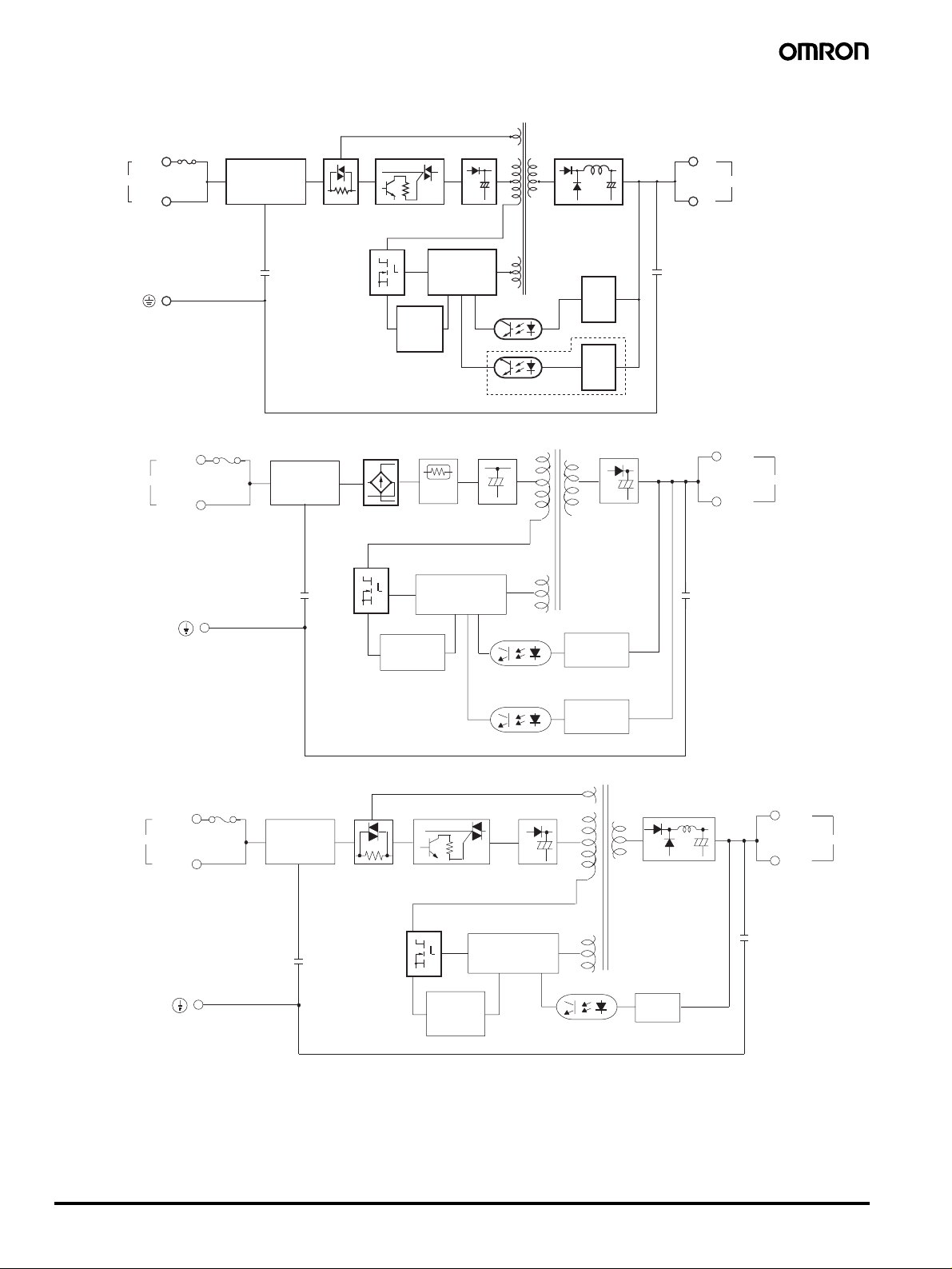
S82J-100@@@@
(100 W, 5-/12-/15-V Output)
AC (L)
Input
AC (N)
* Fuse capacity: 5 A
Fuse*
Noise filter
Noise filter
S82J-10024@@ (100 W, 24-V Output)
AC(L)
Input
AC(N)
Fuse (5 A)
Noise filter
Inrush current
protection circuit
Rectification
100 or 200 V
(selected automatically)
Overcurrent detection
circuit
Inrush current
protection
circuit
Rectification
and smoothing circuit
Control circuit
Photocoupler
Overvoltage protection circuit (5 V only)
Smoothing
circuit
Control circuit
Rectification and
smoothing circuit
Detection
circuit
Overvoltage
detector
Rectification
and
smoothing
circuit
+V
DC Output
−V
+V
DC Output
−V
S82J-15024@@ (150 W)
AC (L)
Input
AC (N)
Fuse (8 A)
Noise filter
Overcurrent
detection
circuit
Inrush current
protection circuit
100 or 200 V
(selected automatically)
Overcurrent
detection
circuit
Photocoupler
Photocoupler
Rectification
Control circuit
Detection
circuit
Overvoltage
detection
circuit
Photocoupler
Rectification
and
smoothing
circuit
Detection
circuit
+V
DC Output
−V
6 Switch Mode Power Supply S82J
 Loading...