

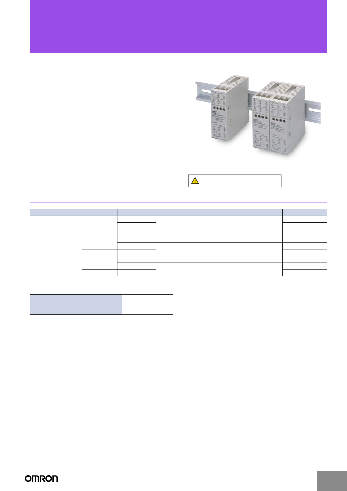
Sensor Controller
S3D2
Offers High-speed Input Response of
0.1 ms and Equipped with Built-in Timer
■ High-speed response of 0.1 ms.
■ Ideal as a two-input Controller.
■ Lineup includes the S3D2-BK with flip-flop functions
convenient for level control, the S3D2-AKD/CKD/CCD with
24-V power supply, and the S3D2-DK/EK with one input/
output OFF-delay (two circuits) useful for load control and
lamp display
■ Power source for the Sensor can be supplied up to
200 mA.
■ Ultra-slim body with 30-mm width.
■ Multi-function model equipped with timer functions also
available.
Be sure to read Safety Precautions on
page 7.
Ordering Information
Power supply voltage Output Timer function Features Model
No
Yes S3D2-EK
100 to 240 VAC
24 VDC
* Models compatible with Sensors for PNP connections are also available. These model numbers have the suffix B (e.g., S3D2-AKB)
Differences from NPN Models
ON 8 to 12 V (2 mA max.)
Input signals
Note: S3D2-AK(B)/-CK(B)/-CC(B) models with UL certification are available.
These model numbers have the suffix US (e.g., S3D2-AK-US).
OFF 0 to 4 V (5 mA min.)
Maximum applied voltage 12 V
Relay
Transistor Yes S3D2-CC *
Relay
Transistor Yes S3D2-CCD
No
No Flip-flop function with two inputs/one output S3D2-BK
Yes
No Single-function with two inputs/one output S3D2-AKD
Yes
Single-function with one input/output (two circuits)
Single-function with two inputs/one output (AND/OR operation)
Multi-function with two inputs/one output
Multi-function with two inputs/one output
S3D2-DK
S3D2-AK *
S3D2-CK *
S3D2-CKD
http://www.ia.omron.com/
(c)Copyright OMRON Corporation 2007 All Rights Reserved.
1

Ratings and Specifications
S3D2
Type
Item Model S3D2-DK S3D2-EK S3D2-AK S3D2-BK S3D2-CK S3D2-CC S3D2-AKD S3D2-CKD S3D2-CCD
Rated supply
voltage
Power consumption 15 VA max. 2.5 VA max. (excluding Sensor power supply)
Power supply for
Sensor
Connected Sensor NPN transistor output (with sinking current of 18 mA min.) or contact output
ON 0 to 4 V (5 mA min.)
OFF 8 to 12 V (2 mA max.) 8 to 30 V (2 mA max.)
Input
signals
Input response time 0.1 ms
Output minimum
pulse width
Control output
Output response
time
Timer functions * ---
Other functions Signal input reverse
Maximum allowable
time of momentary
power failure
Ambient
temperature range
Ambient humidity
range
Noise immunity
Dielectric strength
Vibration
(destruction)
Weight Approx. 140 g
* The timer will not operate in response to input signals received within 50 ms after the Controller power is turned ON.
Shortcircuit
current
Maximum
applied
voltage
Two inputs/
two outputs
Single-
function
100 to 240 VAC ± 10% 50/60Hz 24 VDC ± 10%
12 VDC ± 10% (includes all variations) , 200 mA max. (with short-circuit protection) 24 VDC (supplied from power supply)
11 mA TYP (18 mA max.)
30 V
10 ms max. 0.5 ms max. 10 ms max. 0.5 ms max.
Relay output SPST-NO
× 2
250 VAC, 2A (cosI = 1)
10 ms max. 0.5 ms max. 10 ms max. 0.5 ms max.
20 ms max.
Operating : 10 to +55qC, Storage: 25 to +65qC (with no icing)
Operating/storage: 35% to 85%
Operating power supply: 1,500 V (p-p) min.; pulse width: 100 ns, 1 Ps; rise time: 1 ns
Input/output: 1,200 V (p-p) min.; pulse width: 100 ns, 1 Ps; rise time: 1 ns
1,500 VAC min.(between power supply terminals and I/O terminals, and between non-current-carrying parts)
10 to 55 Hz, double-amplitude of 0.75 mm for 2 hours each of the X, Y, and Z directions
Single-func-
tion (with
OFF-delay)
OFF-delay
0.1 to 1 s
1 to 10 s
selectable
Single-func-
tion (AND/OR
operation)
Relay output SPDT (shared common)
250 VAC, 3 A (cosI = 1)
(Output
reversible)
AND/OR
operating
mode
selection
Flip-flop
function
IN1 2 ms
IN2 2 ms
---
x Signal input
reverse
x Flip-flop
function
0.1 ms
One-shot, ON-delay,
and OFF-delay
0.1 to 1 s
1 to 10 s
selectable
x Signal input reverse
x Sync mode selection
x AND/OR operating mode
selection
Two inputs/one output
Multi-function
NPN open
collector output,
30 VDC, 100 mA
(NO, NC)
Residual voltage
(ON)1.5 V max.
Leakage current
(OFF): 0.1 mA
max.
0.01 to 0.1 s
0.1 to 1 s
selectable
Single-func-
tion (AND/OR
operation)
Relay output SPDT
250 VAC, 3 A (cosI = 1)
---
x Signal input
reverse
x AND/OR
operating
mode
selection
Operating power supply: 480 V (p-p) min.; pulse
width: 100 ns, 1 Ps; rise time: 1 ns
Input/output:
1,000 V (p-p) min.; pulse width: 100 ns, 1 Ps;
rise time: 1 ns
1,500 VAC min.
(between power supply terminals and non-current-carrying parts)
Multi-function (24 VDC)
NPN open
collector output,
30 VDC, 100 mA
(NO, NC)
Residual voltage
(ON)1.5 V max.
Leakage current
(OFF): 0.1 mA
max.
One-shot, ON-delay,
and OFF-delay
0.1 to 1 s
1 to 10 s
selectable
x Signal input reverse
x Sync mode selection
x AND/OR operating mode
selection
0.01 to 0.1 s
0.1 to 1 s
selectable
http://www.ia.omron.com/
(c)Copyright OMRON Corporation 2007 All Rights Reserved.
2

Output Circuit Diagrams
Note: Numbers in parentheses indicate terminal pin numbers.
Relay Output Model Open Collector Model
S3D2-AK/-AKD/
S3D2-DK/-EK
S3D2-CC/-CCD
-CK/-CKD/-BK
NC
NO
Relay contact
NC (6)
250 VAC 3 A
NO (5)
COM (4)
NO
NO
OUT2 (6)
OUT1 (5)
COM (4)
Input Circuit Diagrams
Note: Numbers in parentheses indicate terminal pin numbers.
Voltage output sensor S3D2
10 to
18 mA
+12 V *
(7), (10)
820 Ω 820 Ω
IN
(8), (11)
0 V
Sensor
main
circuit
+12 V *
R
OUT
0 V
(9), (12)
S3D2
main
circuit
Open collector output sensor S3D2
+12 V *
10 to
18 mA
Sensor
main
circuit
OUT
0 V
NC (6)
30 VDC 100 mA
NO (5)
COM (4)
+12 V *
IN
0 V
S3D2
main
circuit
S3D2
Note: Terminals (7) and (10), and (9) and (12) are
connected internally.
* S3D2-AKD/-CKD/-CCD: +24 V
* S3D2-AKD/-CKD/-CCD: +24 V
Connections
Connection Methods
S3D2-AK/-AKD S3D2-CK/-CKD S3D2-CC/-CCD S3D2-BK S3D2-DK/-EK
INPUT
87 9
+12 V IN 1 0 V
1110 12
+12 V IN 2 0 V
POWER
IN 1 IN 2 OUT
S3D2-AK
SENSOR CONTROLLER
SOURCE:100 to 240VAC 50/60Hz
OUTPUT:3A 250VAC
RESISTIVE LOAD
DC POWER SUPPLY
12VDC 200mA
OUTPUT
54 6
COM NO NC
21 3
100to240VAC FG
INPUT
87 9
+12 V IN 1 0 V
1110 12
+12 V IN 2 0 V
POWER
IN 1 IN 2 OUT
S3D2-CK
SENSOR CONTROLLER
SOURCE:100 to 240VAC 50/60Hz
OUTPUT:3A 250VAC
RESISTIVE LOAD
DC POWER SUPPLY
12VDC 200mA
OUTPUT
54 6
COM NO NC
21 3
100to240VAC FG
OMRON Corporation MADE IN JAPAN OMRON Corporation MADE IN JAPAN
(1), (2): Power supply terminals For S3D2-AKD/-CKD/-CCD
Sensors, provide 24 VDC.
The polarity of terminal (2) is
positive, and terminal (1) is
negative. For other models, supply
100 to 240 VAC.
(3): FG terminal Ground with a ground resistance of
100 : max. in locations subject to
excessive noise.
INPUT
87 9
+12 V IN 1 0 V
1110 12
+12 V IN 2 0 V
POWER
IN 1 IN 2 OUT
S3D2-CC
SENSOR CONTROLLER
SOURCE:100 to 240VAC 50/60Hz
OUTPUT:100mA 30VDC
RESISTIVE LOAD
DC POWER SUPPLY
12VDC 200mA
OUTPUT
54 6
COM NO NC
21 3
100to240VAC FG
INPUT
87 9
+12 V IN 1 0 V
1110 12
+12 V IN 2 0 V
POWER
IN 1 IN 2 OUT
S3D2-BK
SENSOR CONTROLLER
SOURCE:100 to 240VAC 50/60Hz
OUTPUT:3A 250VAC
RESISTIVE LOAD
DC POWER SUPPLY
12VDC 200mA
OUTPUT
54 6
COM NO NC
21 3
100to240VAC FG
OMRON Corporation MADE IN JAPANOMRON Corporation MADE IN JAPAN
(4) to (6): Output terminals
(7), (10): Power supply terminals for S3D2-AKD/-CKD/-CCD
Sensors (+24 V), and other models (+12 V)
(9), (12): Power supply terminals for the Sensor (0 V)
(8), (11): Output terminals for the Sensor
Connect the Sensor output lines.
INPUT
87 9
+12 V IN 1 0 V
1110 12
+12 V IN 2 0 V
POWER
OUT1 OUT2
S3D2-EK
SENSOR CONTROLLER
SOURCE:100 to 240VAC 50/60Hz
OUTPUT:2A 250VAC
RESISTIVE LOAD
DC POWER SUPPLY
12VDC 200mA
OUTPUT
54 6
COM OUT1 OUT2
21 3
100to240VAC FG
OMRON Corporation MADE IN JAPAN
http://www.ia.omron.com/
(c)Copyright OMRON Corporation 2007 All Rights Reserved.
3

S3D2
Sensor Connections
Two-wire Sensors (NPN Models)
Brown
Sensor
main
circuit
Blue
Note: Numbers in parentheses indicate terminal pin numbers.
Contact Output Sensors
x The S3D2 has a high-speed input response of 0.1 ms, which may
cause contact output models (relay output, micro-switches, etc.) to
receive unnecessary input from contact bounce and chattering.
+12 V
(7), (10)
(8), (11)
0 V
(9), (12)
IN
S3D2
main
circuit
Example of Unconnectable Sensor Model
Type Proximity Sensor
Model TL-G3D, TL-L100, etc.
12 V
Sink current of NPN output:
Details
2 mA max.
2 mA max.
(Sensors that cannot switch
Output
18 mA or higher are unconnectable)
0 V
Wired OR Transistor Output
Sensor 1
+12 V
(7), (10)
Sensor
main
circuit
Sensor 2
Sensor
main
circuit
(8), (11)
0 V
(9), (12)
IN
Note: Numbers in parentheses indicate terminal pin numbers.
x Wired OR for “Object Detected” Signals
(e.g., Proximity Sensors with NO Outputs)
The input would be an OR of “object detected” signals using a wired
OR of Sensors that turn ON the output transistor when an object is
detected. The S3D2’s input signal selector switch can be set to
reverse this operation and produce an input that would be an AND
of “object not detected” signals.
x Wired OR for “Object Not Detected” Signals
(e.g., Proximity Sensors with NC Outputs)
The input would be an OR of “object not detected” signals using a
wired OR of Sensors that turn ON the output transistor when an
object is not detected. The S3D2’s input signal selector switch can
be set to reverse this operation and produce an input that would be
an AND of “object detected” signals.
S3D2
main
circuit
Load Connection
Connecting Loads to Collector Side
NC (6)
NO (5)
COM (4)
Load
Load
DC
Connecting Loads to Emitter Side
NC (6)
NO (5)
COM (4)
Load
DC
Note: 1. Numbers in parentheses indicate terminal
numbers.
2. Connect either the NC or NO terminals for the
Emitter common. The solid line indicates the
NC terminal and the broken line indicates the
NO terminal.
http://www.ia.omron.com/
(c)Copyright OMRON Corporation 2007 All Rights Reserved.
4

Nomenclature
S3D2-AK/-AKD S3D2-CK/-CKD/-CC/-CCD S3D2-BK S3D2-DK S3D2-EK
S3D2
(1)
(2)
(5)
(2)
(1)
(4)
(5)
(3)
(7)
(6)
(9) (10)
(11) (12)
(3)
(4)
(6)
(8)
(1)
(2)
(5)
(4)
(3)
(6)
(1)
(5)
(4)
(6)
(1)
(5)
(12)
No. Name Functions
Lights when the operating power is turned ON and the Sensor power supply is output.
(1) POWER indicator
Not lit when the operating power is turned OFF, or the Sensor power supply is short circuited
(between the +12-V or +24-V terminal and 0-V terminal).
(2) IN1 indicator Lights when the output from the Sensor connected to IN1 is received by IN1 as an input.
(3) IN2 indicator Lights when the output from the Sensor connected to IN2 is received by IN2 as an input.
(4) OUT indicator Lights when the output turns ON.
(5) IN1 input signal selector switch
(6) IN2 input signal selector switch
MODE
(7)
(AND/OR operation selector switch)
NORM: Input as a signal when the Sensor’s output transistor (or contact output) is ON.
INV: Input as a signal when the Sensor’s output transistor (or contact output) is OFF.
AND: The output is turned ON when IN1 and IN2 input signals are both ON.
OR: The output is turned ON when either IN1 or IN2 input signal is ON.
SYNC
(synchronous mode selector
switch)
(8)
(This switch is enabled only when
the AND/OR operation selector is
: The output is turned ON while both IN1 and IN2 input signals are ON.
: If the input signal of IN2 is turned ON (at the rising edge) while the IN1 input signal is ON, the
output is turned ON.*
set to AND.)
Turns timer operation ON/OFF.
(9) TIMER switch
ON: Timer enabled
OFF: Timer disabled
Changes the range for the timer setting time.
x S3D2-CK/-EK
RANGE
(10)
(Timer timing selector switch)
1 s: Setting time is in range from 0.1 to 1s.
10 s: Setting time is in range from 1 to 10s.
x S3D2-CC
0.1 s: Setting time is in range from 0.01 to 0.1s.
1 s: Setting time is in range from 0.1 to 1s.
TIMER MODE
(11)
(Timer operation mode switch)
TIME ADJ.
(12)
(Timer setting adjuster)
* Be sure to set the one-shot timer.
O. S: One-shot timer
ON. D: ON-delay timer
OFF. D: OFF-delay timer
Setting time can be adjusted with the provided screwdriver.
The adjuster rotates 190q.
(4)
(6)
(9)
(10)
http://www.ia.omron.com/
(c)Copyright OMRON Corporation 2007 All Rights Reserved.
5

Operation
e
e
e
e
(
)
e
e
Basic Operation
S3D2-AK@: Basic Operation
One Sensor
IN1 (NORM)
Note: When connecting only one Sensor, be
Two Sensors (AND Operation)
Output (AND)
Two Sensors (OR Operation)
ON
OFF
[IN2 (INV)]
Output
OFF
No connection
ON
sure to set the input selector switch for
the unconnected Sensor to INV.
IN1 (NORM)
IN2 (NORM)
ON
OFF
ON
OFF
ON
OFF
Sensor
Sensor 1
Sensor 2
Brown
Black
Blue
Brown Black Blu
89
7
10 11 12
IN1 IN2
NORM INV
456
123
S3D2-AK/-AKD
Brown
Black Blu
89
7
10 11 12
IN1 IN2
NORM NORM
456
123
S3D2-AK/-AKD
S3D2
S3D2-CK@/-CC@: Timer Operation (AND)
ON
IN1
OFF
ON
IN2
OFF
(See note 1.)
Output (OR)
(See note 2.)
Output (AND)
(See note 3.)
One-shot output
(AND)
(See note 4.)
ON-delay output
(AND)
(See note 5.)
OFF-delay output
AND
Note: 1. IN1 and IN2 send OR outputs.
2. IN1 and IN2 send AND outputs.
3. IN1 and IN2 send AND outputs for T seconds from the rising edge.
4. IN1 and IN2 send AND outputs after a delay of T seconds from the
rising edge.
5. IN1 and IN2 send AND outputs for T seconds from the falling edge.
When only one Sensor is connected to the S3D2-CK@ and
S3D2-CC@, always set the AND/OR selector switch to
MODE
OR .
AND OR
TT
T
T
T
Sensor 1
ON
Sensor 1
OFF
ON
Sensor 2
OFF
(IN1: Wired OR)
Output (OR)
Note: When two Sensors are wired OR and
ON
OFF
then receive input (IN1 or IN2), OR
operation is possible.
Sensor 2
S3D2-AK@ default settings: IN1······NORM, IN2······INV.
If AND operation is used, set IN2 to NORM.
S3D2-BK: Flip-flop Operation
Sensor 1
ts
IN1 (NORM)
IN2 (NORM)
Note: ts t 2ms, tr t 2ms
ON
OFF
ON
OFF
ON
Output
OFF
Input 1 (IN1) takes priority when both
inputs 1 and 2 are received at the
tr
same time.
Sensor 2
Brown
Black
Blue
Brown Black Blu
89
7
10 11 12
IN1 IN2
NORM INV
456
123
S3D2-AK/-AKD
Brown
Black Blu
89
7
10 11 12
IN1 IN2
NORM NORM
456
123
S3D2-BK
S3D2-DK/-EK: Basic Operation
Two Input Signals Output Independently
The S3D2-EK is equipped with an OFF-delay Timer.
Sensor 1
Brown
Black Blu
89
Brown
Blue
Black
7
10 11 12
456
123
S3D2-DK
Sensor 1
(IN1)
OUT1
Sensor 2
(IN2)
OUT2
ON
OFF
ON
OFF
ON
OFF
ON
OFF
Sensor 2
S3D2-DK/-EK: One Sensor with Two Outputs
Terminals (8) and (11) are short-circuited.
Sensor
Brown Black Blu
89
ON
Sensor 1
OFF
ON
OUT1
OUT2
OFF
ON
OFF
T
Note: 1. The time chart above shows the operation for an S3D2-EK when the
timer 1 switch is OFF and the timer 2 switch is ON.
2. Terminals (8) and (11) are short-circuited, and the current from the
S3D2 to the Sensor is 18 u 2 = 36 mA max. (TYP 22 mA) .
7
10 11 12
TIMER1 TIMER2
OFF ON
456
123
S3D2-EK
http://www.ia.omron.com/
(c)Copyright OMRON Corporation 2007 All Rights Reserved.
6

Safety Precautions
Refer to Warranty and Limitations of Liability.
WARNING
This product is not designed or rated for ensuring
safety of persons either directly or indirectly.
Do not use it for such purposes.
Precautions for Safe Use
x Be sure to connect the power supply to the power supply terminals
correctly. Use a power supply with a voltage range of 100 to
240 VAC ± 10%.
Precautions for Correct Use
Do not use the product in atmospheres or environments that exceed
product ratings.
● Wiring
Ground
x FG is a ground terminal. Ground this terminal at a ground
resistance of 100 : max. when installing in locations subject to
excessive noise, or if the S3D2 malfunctions.
x Do not share a ground line with other devices, or connect it to a
structural beam of a building. Doing so will have the opposite effect,
and may adversely affect the Sensor.
S3D2
FG
Ground
resistance of
100 Ω
Storing in a Protective Case
x Take measures to provide adequate heat dissipation. Otherwise,
heat radiation from the body of the S3D2 may cause the insides of
protective casing to heat up.
S3D2-AKD/-CKD/-CCD
x Do not connect a load of 1 A min. to models for which the S3D2
power supply inputs are to be used as is for the Sensor power
supply outputs. Connecting a load of 1 A min. to the Sensor’s power
supply outputs will cause the fuse in the case to break.
Other device
S3D2 Other device
FG
Terminals (7), (10) 24 V
LoadI < 1 A
Terminals (9), (12) 0 V
S3D2
Output
x Connect a surge suppressor or diode in parallel to the load if an
inductive load or other electrical part that generates noise is
connected to the output.
x Connect the cathode side of the diode to the side of the power
supply.
L
Relay contact output
Relay contact output
Open collector output
Surge suppressor
L
Diode
Output Relay Contact
(Not Including S3D2-CC/-CCD/-DK/-EK)
x When using a load (e.g., contactor or valve) that generates an arc
when the circuit is broken, the NC (NO) contact may turn ON before
the NO (NC) contact has opened (turned OFF).
x When using both NO and NC outputs at the same time, incorporate
an arc suppressor (use the CR method, varistor, or other
countermeasure)
● Mounting
Tightening Torque
Using the provided M3.5 screws, tighten the terminal block to a torque
of 0.59 N·m max.
For direct mounting, use M4 screws, and tighten them to a torque of
0.78 N·m max.
Side-by-side Mounting
x When two or more S3D2 are
mounted side by side, be sure
to provide a minimum distance
of 10 mm between them.
Note: Use the PFP-M End Plate for a
space of 10 mm.
x If side-by-side mounting is
unavoidable, refer to the following load derating curve.
Load current (mA)
AC power supply
Surge suppressor
DC power supply
Diode
10 mm
Resistance: 50 Ω
Capacitor: 0.4 μF
Voltage: 200 V
Peak reverse
breakdown voltage is
at least three times
the load voltage.
Average rectified
current: 1 A
End Plate
(PFP-M)
DIN Track
S3D2
http://www.ia.omron.com/
200
100
0
(c)Copyright OMRON Corporation 2007 All Rights Reserved.
Range in which
side-by-side
mounting is
possible
10 20 25 30 40 50 55 60
Ambient temperature (°C)
7

S3D2
x Always lay the S3D2
input lines, output lines,
and the power line
separately. Otherwise,
malfunction due to
noise may occur.
Output lines
(OUT, 100 to 240 VAC)
x The power line, through which
a large current flows (e.g., to
drive a motor) should be wired
at least 200 mm away from the
Provide a distance of 200 mm min.
S3D2.
Dimensions (Unit: mm)
S3D2
S3D2
Input lines
(IN, IN2, +12 V, 0 V)
Power lines
Provide a
distance of
200 mm min.
S3D2
7
75 (no cover)
35.3
30
23.53
51.5
78
* Terminal block screws: M3.5
Mounting Holes
(direct mounting)
Two M4 (or 4.3-dia.) holes
72
80
(DIN Track mounting is also possible.)
±0.3
http://www.ia.omron.com/
(c)Copyright OMRON Corporation 2007 All Rights Reserved.
8

Read and Understand This Catalog
Please read and understand this catalog before purchasing the products. Please consult your OMRON representative if you have any questions or
comments.
Warranty and Limitations of Liability
WARRANTY
OMRON's exclusive warranty is that the products are free from defects in materials and workmanship for a period of one year (or other period if
specifi ed) from date of sale by OMRON.
OMRON MAKES NO WARRANTY OR REPRESENTATION, EXPRESS OR IMPLIED, REGARDING NON-INFRINGEMENT, MERCHANTABILITY, OR
FITNESS FOR PARTICULAR PURPOSE OF THE PRODUCTS. ANY BUYER OR USER ACKNOWLEDGES THAT THE BUYER OR USER ALONE HAS
DETERMINED THAT THE PRODUCTS WILL SUITABLY MEET THE REQUIREMENTS OF THEIR INTENDED USE. OMRON DISCLAIMS ALL OTHER
WARRANTIES, EXPRESS OR IMPLIED.
LIMITATIONS OF LIABILITY
OMRON SHALL NOT BE RESPONSIBLE FOR SPECIAL, INDIRECT, OR CONSEQUENTIAL DAMAGES, LOSS OF PROFITS, OR COMMERCIAL
LOSS IN ANY WAY CONNECTED WITH THE PRODUCTS, WHETHER SUCH CLAIM IS BASED ON CONTRACT, WARRANTY, NEGLIGENCE, OR
STRICT LIABILITY.
In no event shall responsibility of OMRON for any act exceed the individual price of the product on which liability is asserted.
IN NO EVENT SHALL OMRON BE RESPONSIBLE FOR WARRANTY, REPAIR, OR OTHER CLAIMS REGARDING THE PRODUCTS UNLESS
OMRON'S ANALYSIS CONFIRMS THAT THE PRODUCTS WERE PROPERLY HANDLED, STORED, INSTALLED, AND MAINTAINED AND NOT
SUBJECT TO CONTAMINATION, ABUSE, MISUSE, OR INAPPROPRIATE MODIFICATION OR REPAIR.
Application Considerations
SUITABILITY FOR USE
OMRON shall not be responsible for conformity with any standards, codes, or regulations that apply to the combination of products in the customer's
application or use of the product.
At the customer's request, OMRON will provide applicable third party certifi cation documents identifying ratings and limitations of use that apply to the
products. This information by itself is not suffi cient for a complete determination of the suitability of the products in combination with the end product,
machine, system, or other application or use.
The following are some examples of applications for which particular attention must be given. This is not intended to be an exhaustive list of all possible
uses of the products, nor is it intended to imply that the uses listed may be suitable for the products:
• Outdoor use, uses involving potential chemical contamination or electrical interference, or conditions or uses not described in this catalog.
• Nuclear energy control systems, combustion systems, railroad systems, aviation systems, medical equipment, amusement machines, vehicles, safety
equipment, and installations subject to separate industry or government regulations.
• Systems, machines, and equipment that could present a risk to life or property.
Please know and observe all prohibitions of use applicable to the products.
NEVER USE THE PRODUCTS FOR AN APPLICATION INVOLVING SERIOUS RISK TO LIFE OR PROPERTY WITHOUT ENSURING THAT THE
SYSTEM AS A WHOLE HAS BEEN DESIGNED TO ADDRESS THE RISKS, AND THAT THE OMRON PRODUCT IS PROPERLY RATED AND
INSTALLED FOR THE INTENDED USE WITHIN THE OVERALL EQUIPMENT OR SYSTEM.
Disclaimers
CHANGE IN SPECIFICATIONS
Product specifi cations and accessories may be changed at any time based on improvements and other reasons.
It is our practice to change model numbers when published ratings or features are changed, or when signifi cant construction changes are made.
However, some specifi cations of the product may be changed without any notice. When in doubt, special model numbers may be assigned to fi x
or establish key specifi cations for your application on your request. Please consult with your OMRON representative at any time to confi rm actual
specifi cations of purchased product.
DIMENSIONS AND WEIGHTS
Dimensions and weights are nominal and are not to be used for manufacturing purposes, even when tolerances are shown.
ERRORS AND OMISSIONS
The information in this catalog has been carefully checked and is believed to be accurate; however, no responsibility is assumed for clerical,
typographical, or proofreading errors, or omissions.
PERFORMANCE DATA
Performance data given in this catalog is provided as a guide for the user in determining suitability and does not constitute a warranty. It may represent
the result of OMRON’s test conditions, and the users must correlate it to actual application requirements. Actual performance is subject to the OMRON
Warranty and Limitations of Liability.
PROGRAMMABLE PRODUCTS
OMRON shall not be responsible for the user's programming of a programmable product, or any consequence thereof.
COPYRIGHT AND COPY PERMISSION
This catalog shall not be copied for sales or promotions without permission.
This catalog is protected by copyright and is intended solely for use in conjunction with the product. Please notify us before copying or reproducing this
catalog in any manner, for any other purpose. If copying or transmitting this catalog to another, please copy or transmit it in its entirety.
OMRON Corporation
Industrial Automation Company
http://www.ia.omron.com/
In the interest of product improvement, specifications are subject to change without notice.
(c)Copyright OMRON Corporation 2007 All Rights Reserved.
2007.3
 Loading...