

Page 1

Cat. No.W426-E1-09
SYSMAC
CJ1W-NC271/NC471/
NCF71/NCF71-MA
CS1W-NC271/NC471/NCF71
Position Control Units
OPERATION MANUAL
Page 2

CJ1W-NC271/NC471/NCF71/NCF71-MA CS1W-NC271/NC471/NCF71 Position Control Units
Operation Manual
Revised October 2008
Page 3

iv
Page 4

Notice:
r
f
OMRON products are manufactured for use according to proper procedures by a qualified operator
and only for the purposes described in this manual.
The following conventions are used to indicate and classify precautions in this manual. Always heed
the information provided with them. Failure to heed precautions can result in injury to people or damage to property.
!DANGER Indicates an imminently hazardous situation which, if not avoided, will result in death or
serious injury. Additionally, there may be severe property damage.
!WARNING Indicates a potentially hazardous situation which, if not avoided, could result in death or
serious injury. Additionally, there may be severe property damage.
!Caution Indicates a potentially hazardous situation which, if not avoided, may result in minor or
moderate injury, or property damage.
OMRON Product References
All OMRON products are capitalized in this manual. The word “Unit” is also capitalized when it refers to
an OMRON product, regardless of whether or not it appears in the proper name of the product.
The abbreviation “Ch,” which appears in some displays and on some OMRON products, often means
“word” and is abbreviated “Wd” in documentation in this sense.
The abbreviation “PLC” means Programmable Controller. “PC” is used, however, in some Programming Device displays to mean Programmable Controller.
Visual Aids
The following headings appear in the left column of the manual to help you locate different types of
information.
OMRON, 2004
All rights reserved. No part of this publication may be reproduced, stored in a retrieval system, or transmitted, in any form, o
by any means, mechanical, electronic, photocopying, recording, or otherwise, without the prior written permission o
OMRON.
No patent liability is assumed with respect to the use of the information contained herein. Moreover, because OMRON is constantly striving to improve its high-quality products, the information contained in this manual is subject to change without
notice. Every precaution has been taken in the preparation of this manual. Nevertheless, OMRON assumes no responsibility
for errors or omissions. Neither is any liability assumed for damages resulting from the use of the information contained in
this publication.
Note Indicates information of particular interest for efficient and convenient opera-
tion of the product.
1,2,3... 1. Indicates lists of one sort or another, such as procedures, checklists, etc.
v
Page 5

vi
Page 6

TABLE OF CONTENTS
PRECAUTIONS . . . . . . . . . . . . . . . . . . . . . . . . . . . . . . . . . . . xxiii
1 Intended Audience. . . . . . . . . . . . . . . . . . . . . . . . . . . . . . . . . . . . . . . . . . . . . . . . . . . . . . . . . xxiv
2 General Precautions. . . . . . . . . . . . . . . . . . . . . . . . . . . . . . . . . . . . . . . . . . . . . . . . . . . . . . . . xxiv
3 Safety Precautions . . . . . . . . . . . . . . . . . . . . . . . . . . . . . . . . . . . . . . . . . . . . . . . . . . . . . . . . . xxiv
4 Operating Environment Precautions . . . . . . . . . . . . . . . . . . . . . . . . . . . . . . . . . . . . . . . . . . . xxv
5 Application Precautions. . . . . . . . . . . . . . . . . . . . . . . . . . . . . . . . . . . . . . . . . . . . . . . . . . . . . xxvi
6 Conformance to EC Directives . . . . . . . . . . . . . . . . . . . . . . . . . . . . . . . . . . . . . . . . . . . . . . . xxviii
SECTION 1
Features and System Configuration . . . . . . . . . . . . . . . . . . . 1
1-1 Features . . . . . . . . . . . . . . . . . . . . . . . . . . . . . . . . . . . . . . . . . . . . . . . . . . . . . . . . . . . . . . . . . 2
1-2 System Configuration . . . . . . . . . . . . . . . . . . . . . . . . . . . . . . . . . . . . . . . . . . . . . . . . . . . . . . 3
1-3 Basic Operations . . . . . . . . . . . . . . . . . . . . . . . . . . . . . . . . . . . . . . . . . . . . . . . . . . . . . . . . . . 4
1-4 List of Functions and Specifications . . . . . . . . . . . . . . . . . . . . . . . . . . . . . . . . . . . . . . . . . . . 6
1-5 List of Functions by Purpose. . . . . . . . . . . . . . . . . . . . . . . . . . . . . . . . . . . . . . . . . . . . . . . . .8
1-6 Comparison with Existing Models . . . . . . . . . . . . . . . . . . . . . . . . . . . . . . . . . . . . . . . . . . . . 9
SECTION 2
Basic Procedures . . . . . . . . . . . . . . . . . . . . . . . . . . . . . . . . . . . 11
2-1 Basic Flow of Operations . . . . . . . . . . . . . . . . . . . . . . . . . . . . . . . . . . . . . . . . . . . . . . . . . . .12
2-2 Starting Operation . . . . . . . . . . . . . . . . . . . . . . . . . . . . . . . . . . . . . . . . . . . . . . . . . . . . . . . . . 16
SECTION 3
Installation and Wiring . . . . . . . . . . . . . . . . . . . . . . . . . . . . . 31
3-1 Nomenclature and Functions. . . . . . . . . . . . . . . . . . . . . . . . . . . . . . . . . . . . . . . . . . . . . . . . . 32
3-2 Installing the Position Control Unit. . . . . . . . . . . . . . . . . . . . . . . . . . . . . . . . . . . . . . . . . . . . 35
3-3 External I/O Circuits . . . . . . . . . . . . . . . . . . . . . . . . . . . . . . . . . . . . . . . . . . . . . . . . . . . . . . . 39
3-4 Wiring . . . . . . . . . . . . . . . . . . . . . . . . . . . . . . . . . . . . . . . . . . . . . . . . . . . . . . . . . . . . . . . . . . 53
SECTION 4
Data Areas . . . . . . . . . . . . . . . . . . . . . . . . . . . . . . . . . . . . . . . . 71
4-1 Overall Structure . . . . . . . . . . . . . . . . . . . . . . . . . . . . . . . . . . . . . . . . . . . . . . . . . . . . . . . . . . 72
4-2 Data Areas . . . . . . . . . . . . . . . . . . . . . . . . . . . . . . . . . . . . . . . . . . . . . . . . . . . . . . . . . . . . . . . 75
4-3 Common Parameter Area . . . . . . . . . . . . . . . . . . . . . . . . . . . . . . . . . . . . . . . . . . . . . . . . . . . 92
4-4 Axis Parameter Area . . . . . . . . . . . . . . . . . . . . . . . . . . . . . . . . . . . . . . . . . . . . . . . . . . . . . . . 97
4-5 Servo Parameter Area . . . . . . . . . . . . . . . . . . . . . . . . . . . . . . . . . . . . . . . . . . . . . . . . . . . . . . 100
4-6 Common Operating Memory Area . . . . . . . . . . . . . . . . . . . . . . . . . . . . . . . . . . . . . . . . . . . . 164
4-7 Axis Operating Output Memory Areas . . . . . . . . . . . . . . . . . . . . . . . . . . . . . . . . . . . . . . . . . 170
4-8 Axis Operating Input Memory Areas . . . . . . . . . . . . . . . . . . . . . . . . . . . . . . . . . . . . . . . . . . 179
vii
Page 7

TABLE OF CONTENTS
SECTION 5
Transferring and Saving Data . . . . . . . . . . . . . . . . . . . . . . . . 201
5-1 Transferring Data. . . . . . . . . . . . . . . . . . . . . . . . . . . . . . . . . . . . . . . . . . . . . . . . . . . . . . . . . . 202
5-2 Transferring PCU Parameters . . . . . . . . . . . . . . . . . . . . . . . . . . . . . . . . . . . . . . . . . . . . . . . . 204
5-3 Transferring Servo Parameters . . . . . . . . . . . . . . . . . . . . . . . . . . . . . . . . . . . . . . . . . . . . . . . 210
SECTION 6
MECHATROLINK . . . . . . . . . . . . . . . . . . . . . . . . . . . . . . . . 221
6-1 MECHATROLINK Overview . . . . . . . . . . . . . . . . . . . . . . . . . . . . . . . . . . . . . . . . . . . . . . . . 222
6-2 MECHATROLINK Settings . . . . . . . . . . . . . . . . . . . . . . . . . . . . . . . . . . . . . . . . . . . . . . . . . 223
6-3 MECHATROLINK Communications Control . . . . . . . . . . . . . . . . . . . . . . . . . . . . . . . . . . . 232
6-4 Standard Settings for Servo Drives Using MECHATROLINK. . . . . . . . . . . . . . . . . . . . . . . 247
SECTION 7
Position Control Structure . . . . . . . . . . . . . . . . . . . . . . . . . . . 255
7-1 PCU Control System . . . . . . . . . . . . . . . . . . . . . . . . . . . . . . . . . . . . . . . . . . . . . . . . . . . . . . . 256
7-2 Control Units . . . . . . . . . . . . . . . . . . . . . . . . . . . . . . . . . . . . . . . . . . . . . . . . . . . . . . . . . . . . . 257
7-3 Coordinate System and Present Position. . . . . . . . . . . . . . . . . . . . . . . . . . . . . . . . . . . . . . . . 260
7-4 Acceleration and Deceleration Operations . . . . . . . . . . . . . . . . . . . . . . . . . . . . . . . . . . . . . . 261
7-5 Limit Input Operations . . . . . . . . . . . . . . . . . . . . . . . . . . . . . . . . . . . . . . . . . . . . . . . . . . . . . 270
SECTION 8
Defining the Origin . . . . . . . . . . . . . . . . . . . . . . . . . . . . . . . . . 273
8-1 Overview . . . . . . . . . . . . . . . . . . . . . . . . . . . . . . . . . . . . . . . . . . . . . . . . . . . . . . . . . . . . . . . . 274
8-2 Origin Search Operation . . . . . . . . . . . . . . . . . . . . . . . . . . . . . . . . . . . . . . . . . . . . . . . . . . . . 275
8-3 Present Position Preset. . . . . . . . . . . . . . . . . . . . . . . . . . . . . . . . . . . . . . . . . . . . . . . . . . . . . . 296
8-4 Origin Return. . . . . . . . . . . . . . . . . . . . . . . . . . . . . . . . . . . . . . . . . . . . . . . . . . . . . . . . . . . . . 298
8-5 Phase Z Margin . . . . . . . . . . . . . . . . . . . . . . . . . . . . . . . . . . . . . . . . . . . . . . . . . . . . . . . . . . . 303
8-6 Absolute Encoder Origin. . . . . . . . . . . . . . . . . . . . . . . . . . . . . . . . . . . . . . . . . . . . . . . . . . . .305
SECTION 9
Positioning . . . . . . . . . . . . . . . . . . . . . . . . . . . . . . . . . . . . . . . . 317
9-1 Direct Operation Overview . . . . . . . . . . . . . . . . . . . . . . . . . . . . . . . . . . . . . . . . . . . . . . . . . .318
9-2 Direct Operation Procedure. . . . . . . . . . . . . . . . . . . . . . . . . . . . . . . . . . . . . . . . . . . . . . . . . .319
9-3 PCU Data Settings for Direct Operation . . . . . . . . . . . . . . . . . . . . . . . . . . . . . . . . . . . . . . . . 319
9-4 Using Direct Operation . . . . . . . . . . . . . . . . . . . . . . . . . . . . . . . . . . . . . . . . . . . . . . . . . . . . . 323
9-5 Interrupt Feeding . . . . . . . . . . . . . . . . . . . . . . . . . . . . . . . . . . . . . . . . . . . . . . . . . . . . . . . . . . 331
9-6 Torque Limit Function. . . . . . . . . . . . . . . . . . . . . . . . . . . . . . . . . . . . . . . . . . . . . . . . . . . . . . 334
9-7 Linear Interpolation . . . . . . . . . . . . . . . . . . . . . . . . . . . . . . . . . . . . . . . . . . . . . . . . . . . . . . . . 335
viii
Page 8

TABLE OF CONTENTS
SECTION 10
Other Operations . . . . . . . . . . . . . . . . . . . . . . . . . . . . . . . . . . 349
10-1 Servo Lock/Unlock . . . . . . . . . . . . . . . . . . . . . . . . . . . . . . . . . . . . . . . . . . . . . . . . . . . . . . . . 350
10-2 Jogging. . . . . . . . . . . . . . . . . . . . . . . . . . . . . . . . . . . . . . . . . . . . . . . . . . . . . . . . . . . . . . . . . . 351
10-3 Override . . . . . . . . . . . . . . . . . . . . . . . . . . . . . . . . . . . . . . . . . . . . . . . . . . . . . . . . . . . . . . . . . 355
10-4 Torque Limits. . . . . . . . . . . . . . . . . . . . . . . . . . . . . . . . . . . . . . . . . . . . . . . . . . . . . . . . . . . . . 357
10-5 Speed Control . . . . . . . . . . . . . . . . . . . . . . . . . . . . . . . . . . . . . . . . . . . . . . . . . . . . . . . . . . . . 364
10-6 Torque Control. . . . . . . . . . . . . . . . . . . . . . . . . . . . . . . . . . . . . . . . . . . . . . . . . . . . . . . . . . . . 375
10-7 Backlash Compensation. . . . . . . . . . . . . . . . . . . . . . . . . . . . . . . . . . . . . . . . . . . . . . . . . . . . . 381
10-8 Software Limits . . . . . . . . . . . . . . . . . . . . . . . . . . . . . . . . . . . . . . . . . . . . . . . . . . . . . . . . . . . 383
10-9 Stop Functions . . . . . . . . . . . . . . . . . . . . . . . . . . . . . . . . . . . . . . . . . . . . . . . . . . . . . . . . . . . . 388
10-10 DEVIATION COUNTER RESET. . . . . . . . . . . . . . . . . . . . . . . . . . . . . . . . . . . . . . . . . . . . . 393
SECTION 11
Sample Programs . . . . . . . . . . . . . . . . . . . . . . . . . . . . . . . . . . 397
11-1 Overview . . . . . . . . . . . . . . . . . . . . . . . . . . . . . . . . . . . . . . . . . . . . . . . . . . . . . . . . . . . . . . . . 398
11-2 Basic Program Examples. . . . . . . . . . . . . . . . . . . . . . . . . . . . . . . . . . . . . . . . . . . . . . . . . . . .399
11-3 Application Examples . . . . . . . . . . . . . . . . . . . . . . . . . . . . . . . . . . . . . . . . . . . . . . . . . . . . . . 424
SECTION 12
Troubleshooting . . . . . . . . . . . . . . . . . . . . . . . . . . . . . . . . . . . 455
12-1 Overview of PCU Errors . . . . . . . . . . . . . . . . . . . . . . . . . . . . . . . . . . . . . . . . . . . . . . . . . . . . 456
12-2 Troubleshooting Procedure . . . . . . . . . . . . . . . . . . . . . . . . . . . . . . . . . . . . . . . . . . . . . . . . . .460
12-3 LED Error Indicators . . . . . . . . . . . . . . . . . . . . . . . . . . . . . . . . . . . . . . . . . . . . . . . . . . . . . . . 461
12-4 Error Codes . . . . . . . . . . . . . . . . . . . . . . . . . . . . . . . . . . . . . . . . . . . . . . . . . . . . . . . . . . . . . . 464
12-5 Troubleshooting. . . . . . . . . . . . . . . . . . . . . . . . . . . . . . . . . . . . . . . . . . . . . . . . . . . . . . . . . . . 477
12-6 Error Reset. . . . . . . . . . . . . . . . . . . . . . . . . . . . . . . . . . . . . . . . . . . . . . . . . . . . . . . . . . . . . . . 482
12-7 CPU Unit Error Display. . . . . . . . . . . . . . . . . . . . . . . . . . . . . . . . . . . . . . . . . . . . . . . . . . . . . 484
SECTION 13
Maintenance and Inspection . . . . . . . . . . . . . . . . . . . . . . . . . 485
13-1 Inspection. . . . . . . . . . . . . . . . . . . . . . . . . . . . . . . . . . . . . . . . . . . . . . . . . . . . . . . . . . . . . . . . 486
13-2 Inspection Points . . . . . . . . . . . . . . . . . . . . . . . . . . . . . . . . . . . . . . . . . . . . . . . . . . . . . . . . . . 486
13-3 Handling Precautions. . . . . . . . . . . . . . . . . . . . . . . . . . . . . . . . . . . . . . . . . . . . . . . . . . . . . . . 487
13-4 Procedure for Replacing a PCU. . . . . . . . . . . . . . . . . . . . . . . . . . . . . . . . . . . . . . . . . . . . . . . 487
ix
Page 9

TABLE OF CONTENTS
Appendices
A Performance Characteristics . . . . . . . . . . . . . . . . . . . . . . . . . . . . . . . . . . . . . . . . . . . . . . . . . 491
B List of Parameters . . . . . . . . . . . . . . . . . . . . . . . . . . . . . . . . . . . . . . . . . . . . . . . . . . . . . . . . . 495
C Operation Area I/O Allocations . . . . . . . . . . . . . . . . . . . . . . . . . . . . . . . . . . . . . . . . . . . . . . 559
D List of Error Codes . . . . . . . . . . . . . . . . . . . . . . . . . . . . . . . . . . . . . . . . . . . . . . . . . . . . . . . . 571
E Changing to CS1W/CJ1W-NC271/471/F71 from CS1W/CJ1W-NC113/133/213/233/413/433 579
F Additional Functions for the CJ1W-NCF71-MA . . . . . . . . . . . . . . . . . . . . . . . . . . . . . . . . . 601
Index. . . . . . . . . . . . . . . . . . . . . . . . . . . . . . . . . . . . . . . . . . . . . 605
Revision History . . . . . . . . . . . . . . . . . . . . . . . . . . . . . . . . . . . 615
x
Page 10

About this Manual:
This manual describes the installation and operation of the CJ1W-NC271/NC471/NCF71/NCF71-MA
and CS1W-NC271/NC471/NCF71 Position Control Units and includes the sections described below.
Please read this manual carefully and be sure you understand the information provided before
attempting to install or operate the Position Control Unit. Be sure to read the precautions provided in
the following section.
Precautions provide general precautions for using the Position Control Unit, Programmable Controller,
and related devices.
Section 1 introduces the features of the Position Control Unit, explains the system configuration in
which it is used, and also provides information on basic operations, functions and specifications.
Section 2 provides an overview of the procedures required to use the Position Control Unit.
Section 3 provides information on nomenclature and functions, and describes the procedures required
for wiring and installation. Information on the MECHATROLINK-II Application Module is also provided.
Section 4 provides an overview of the parameter and data settings used in Position Control Unit operation and provides information on memory allocations.
Section 5 explains how to transfer and save parameters and data using the data transfer bits.
Section 6 provides an overview of MECHATROLINK communications, and includes information on
settings and procedures required to use MECHATROLINK with the Position Control Unit.
Section 7 provides an overview of the control system used by the Position Control Unit, including information on the control units, coordinate system, acceleration/deceleration operations, and limit input
operations.
Section 8 provides information on the various operations used to determine the origin, including origin
searches, origin returns, presetting the present position, calculating phase Z margins, and using the
absolute encoder.
Section 9 provides an overview of direct operation and describes the parameter settings, data settings, and procedures required to perform direct operation. Information on interrupt feeding and torque
limits is also provided here.
Section 10 describes the servo lock/unlock, jogging, override, torque limits, speed control, torque control, backlash compensation, software limits, and stop functions.
Section 11 provides basic program examples and application examples for using the Position Control
Unit.
Section 12 provides information on troubleshooting errors that may occur, including details on the
meaning of indicator displays and error codes, and the procedures required to reset errors in the Unit
or axes.
Section 13 describes methods for inspecting and maintaining the Position Control Unit and the procedure required to replace a Position Control Unit.
The Appendices provide information on the performance characteristics, lists of parameters, I/O allocations in the operation areas, lists of error codes, alarm/warning displays, and information required
when changing to the CJ1W-NC271/NC471/NCF71/NCF71-MA or CS1W-NC271/NC471/NCF71 from
a CJ1W/CS1W-NC113/133/213/233/413/433 Position Control Unit.
!WARNING Failure to read and understand the information provided in this manual may result in per-
sonal injury or death, damage to the product, or product failure. Please read each section
in its entirety and be sure you understand the information provided in the section and
related sections before attempting any of the procedures or operations given.
xi
Page 11
Unit Versions of Position Control Units
Unit Versions A “unit version” has been introduced to manage Position Control Units accord-
ing to differences in functionality accompanying Unit upgrades.
Notation of Unit Versions
on Products
CJ1W-NCF71
N
C
F71
M
LK
R
U
N
E
R
C
E
R
H
E
R
M
D
C
E
B
U
N
F
IT
A
0
9
1
8
No.
2
7
3
6
4
5
M
LK
Confirming Unit Versions
with Support Software
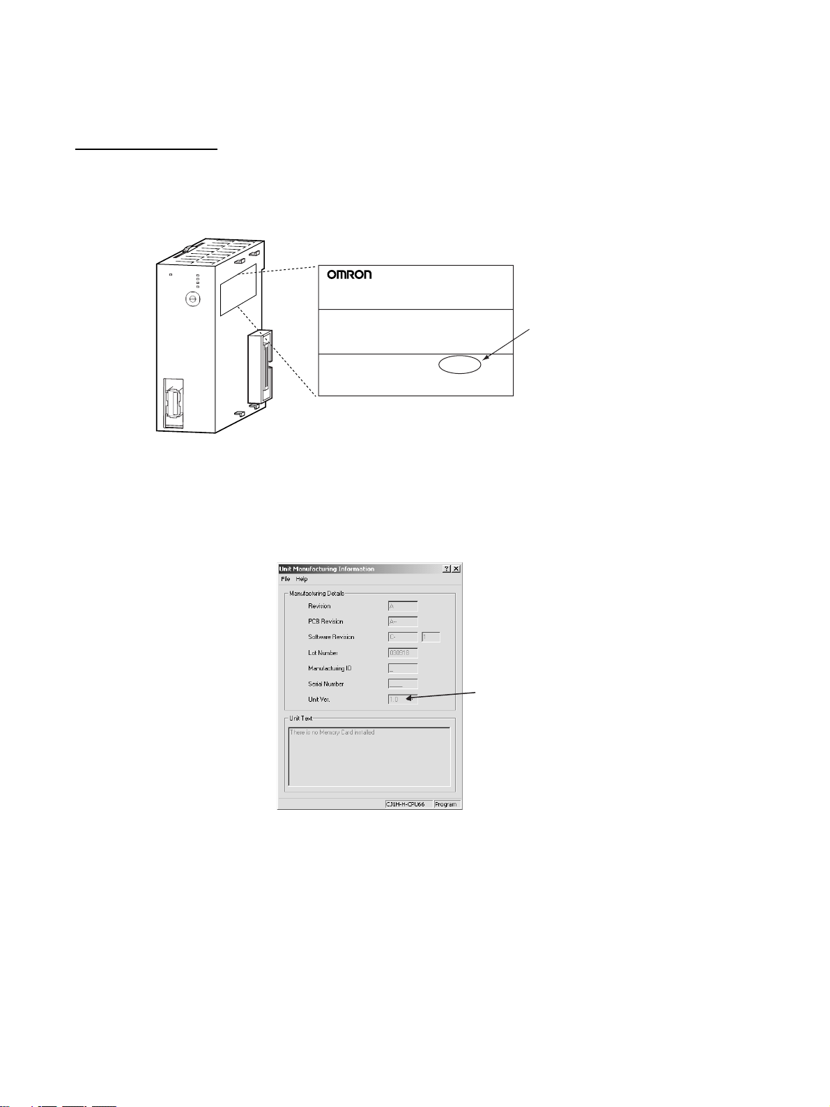
The unit version is given to the right of the lot number on the nameplate of the
products for which unit versions are being managed, as shown below.
Product nameplate
CJ1W-NCF71
NC UNIT
Unit version
Example for unit version 1.0
Lot No. 040401 0000 Ver.1.0
OMRON Corporation MADE IN JAPAN
The unit version of Position Control Units starts with unit version 1.0.
CX-Programmer version 4.0 can be used to confirm the unit version using the
Unit Manufacturing Information.
In the IO Table Window, right-click the Position Control Unit and select Unit
Manufacturing information.
The following Unit Manufacturing information Dialog Box will be displayed.
Unit version
The unit version is displayed as 1.0 in the Unit Version Number field of the
above example. Use the above display to confirm the unit version of the Unit
connected online.
Using Unit Version Label A unit version label is provided with the Position Control Unit. This label can
be attached to the front of the Position Control Unit to differentiate between
Position Control Units with different unit versions.
xii
Page 12

Functions Supported According to Position Control Unit Versions
Model CJ1W-NC@71/CS1W-NC@71
Unit Ver. 1 .0 Unit Ver. 1.1 Unit Ver. 1.2 Unit Ver. 1.3 Unit Ver. 2. 0 Unit Ver. 2.1
Linear interpolation --- Supported. Supported. Supported. Supported. Supported.
Absolute encoder setup function --- --- Supported. Supported. Supported. Supported.
Deviation counter reset --- --- --- Supported. Supported. Supported.
Establishing connections even
when there are unconnected
axes or axes with alarms that
cannot be cleared
Transferring servo parameters
even when there is an axis error
Creating servo locks during software limit detection when an
absolute encoder is used
Driver main circuit OFF error
detection only when the servo is
locked
Using Holding Area address
H512 and onwards for function
block address allocations
Addition of supported models:
SMARTSTEP Junior Servo
Drives (R7D-ZN@-ML2)
Addition of rejoin function --- --- --- --- Supported. Supported.
Eliminating connection restric-
tion when Servo Drive alarms
occur (enabling connection
when alarm A.C90 occurs)
Addition of origin search operation modes
Addition of origin search preset
function
Faster setting for transfer cycle
and communications cycle
when setting the absolute
encoder PG zero point position
offset with an origin search
--- --- --- Supported. Supported. Supported.
--- --- --- Supported. Supported. Supported.
--- --- --- Supported. Supported. Supported.
--- --- --- Supported. Supported. Supported.
--- --- --- Supported. Supported. Supported.
--- --- --- --- Supported. Supported.
--- --- --- --- Supported. Supported.
--- --- --- --- Supported. Supported.
--- --- --- --- Supported. Supported.
--- --- --- --- --- Supported.
xiii
Page 13

Upgrades Made According to Unit Versions of the Position Control Unit
Unit Version 1.0 to Unit Version 1.1
Functional upgrade Unit version 1.0 Unit version 1.1
Addition of linear interpolation
function
Linear interpolation cannot be used.
Linear interpolation can be performed for
positioning operations combining one or
more axes.
Linear interpolation can performed for up to
four axes each of axes 1 to 4 and axes 5 to 8
for Servo Drive axes connected to the Position Control Unit. (Refer to 9-7 Linear Inter-
polation.)
Unit Version 1.1 to Unit Version 1.2
Functional upgrade Unit version 1.1 Unit version 1.2
Addition of setup function for
absolute encoders
An absolute encoder must be set up the
first time it is used, when the rotation data
is initialized to 0, or when the absolute
encoder is left for a long period of time
without the battery connected.
With Position Control Units with unit version 1.1 or earlier, the following operation
is used to set up the absolute encoder.
• Special software (personal computer
monitoring software) must be connected
to the Servo Drive to perform the setup
operation.
With Position Control Units with unit version
1.2 or later, the following operation can be
used to set up the absolute encoder.
• Special software (personal computer monitoring software) can be connected to the
Servo Drive to perform the setup operation.
• When the Position Control Unit is used with
a CPU Unit with unit version 3.0 or later, the
absolute encoder can be set up from the
program by using a function block from the
OMRON FB Library.
• The absolute encoder can be set up from
the CX-Motion-NCF. (Refer to 8-6-4
Absolute Encoder Setup.)
Unit Version 1.2 to Unit Version 1.3
Functional upgrade Unit version 1.2 Unit version 1.3
Addition of deviation counter
reset function
The deviation counter in the Servo Drive
cannot be reset from the Position Control
Unit during position control operations.
The deviation counter in the Servo Drive can
be reset from the Position Control Unit during
position control operations.
To deviation reset function in the Position
Control Unit works by sending a movement
command in the opposite direction and of the
same size as the current position deviation
so that the current command position equals
the current feedback position.
(Refer to 10-10 DEVIATION COUNTER
RESET.)
xiv
Page 14

Functional upgrade Unit version 1.2 Unit version 1.3
Establishing connections
when there are unconnected
axes or axes with alarms that
cannot be cleared
Transferring parameters when
there are axis errors
Locking the servo when a
software limit is being
detected for a Motor with an
absolute encoder
If any of the axes registered in the scan list
are not connected, have the control power
supply interrupted, or have an alarm that
can be reset only by cycling the power
supply, an MLK initialization error (Unit
error code 0020 (hex) will occur after the
connections are established and operations using MECHATROLINK communications will not be possible any axes,
including those without errors.
To start MECHATROLINK communications
normally, all errors must be cleared for all
axes registered in the scan list before connections can be established.
Servo parameters cannot be transferred
(i.e., written, read, or saved) for axes with
errors. The errors must first be reset to
clear the axis error status before Servo
parameters can be transferred.
If an attempt is made to lock the Servo
when an absolute encoder is used, the
software limits are enabled, and the
present position is within the software limit
area, a software limit error will occur and
the Servo lock operation will be canceled.
To lock the Servo in the above situation,
the software limit must first be disabled.
Axis operations using MECHATROLINK communications are possible for any axes registered in the scan list and for which
MECHATROLINK communications have
been started (see note) regardless of
whether there are Servo Drive alarms.
If there are any axes with alarms, they will be
indicated by the Error Flags and error code in
the Axis Operating Input Memory Areas.
If there are alarms in the Servo Drive that can
be cleared only by recycling the power, they
will be detected as Unit errors (MLK initialization errors) for Units with unit version 1.1 or
earlier, but they will be detected in the individual axis areas.
Note If R88D-WN@-ML2 W-series Servo
Drives (Models with Built-in MECHATROLINK-II Communications) are connected, an encoder communications
error (A.C9@) will occur in the Servo
Drive and it will not be possible to start
MECHATROLINK communications for
Units with unit version 1.3 or earlier.
(Refer to 6-3-2 MECHATROLINK Communi-
cations Status.)
Servo parameters can be transferred (i.e.,
written, read, or saved) for axes with errors. If
the axis error already exists, it will not be
overwritten even if an error occurs during
parameter transfer.
If Servo parameters are written when there is
an axis error, be sure to confirm that the
parameters were transferred correctly.
(Refer to 5-3 Transferring Servo Parameters.)
The Servo can be locked at any position,
regardless of the type of encoder and the
software limit settings.
(Refer to 10-8-4 Software Limit Operation.)
xv
Page 15

Functional upgrade Unit version 1.2 Unit version 1.3
Detecting driver main circuit
OFF errors only when the
Servo is locked
Allocating holding addresses
H512 and higher as function
block addresses
Servo Drive main circuit OFF errors are
detected regardless of whether the Servo
is locked for the axis. Once a Servo Drive
main circuit OFF error is detected, it will
continue to be detected even if the error is
reset until the main circuit power supply is
restored.
The function blocks in the OMRON FB
Library for the Position Control Unit cannot
be used if H512 (default setting) or higher
are allocated for non-holding areas of function block addresses.
If H512 or higher are allocated, a function
block error will occur when the function
block is executed.
The CX-Programmer must be used to
change the setting to other unused words
(e.g., in the DM or EM Area).
Servo Drive main circuit OFF errors are
detected only when the Servo is locked for
the axis.
The Position Control Unit will automatically
unlock the Servo when a Servo Drive main
circuit OFF error is detected, allowing the
error to be cleared even while the main circuit
power supply is interrupted.
If an attempt is made to lock the Servo while
the main circuit power supply is interrupted, a
Servo Drive main circuit OFF error will be
detected again.
(Refer to 12-4-2 List of Error Codes.)
The function blocks in the OMRON FB
Library for the Position Control Unit can be
used if H512 (default setting) or higher are
allocated for non-holding areas of function
block addresses.
Unit Version 1.3 to Unit Version 2.0
Functional upgrade Unit version 1.3 Unit version 2.0
Addition of applicable models
Applicable Models
•R88D-WT@W-series Servo Drives (with
JUSP-NS115 MECHATROLINK-II Application Module mounted)
•R88D-WN@-ML2 W-series Servo Drives
(Models with Built-in MECHATROLINK-II
Communications)
Applicable Models
•R88D-WT@W-series Servo Drives (with
JUSP-NS115 MECHATROLINK-II Application Module mounted)
•R88D-WN@-ML2 W-series Servo Drives
(Models with Built-in MECHATROLINK-II
Communications)
•R7D-ZN@-ML2 SMARTSTEP Junior Servo
Drive (Models with Built-in MECHATROLINK-II Communications)
xvi
Page 16
Functional upgrade Unit version 1.3 Unit version 2.0
r
Addition of rejoin function MECHATROLINK communications are
started and stopped at the same time for
all axes registered in the scan list.
The following functions are supported in
addition to starting and stopping MECHATROLINK communications for all axes at the
same time.
• Rejoin Function
An axis for which communications have
been stopped, e.g., due to a communications error, can be restarted without stopping communications for the other axes.
(Refer to 6-3-4 Rejoining the Connection.)
• Setting the Axes to Be Connected
Axes registered in the scan list can be set
temporarily so that they are not registered.
The axes can be set so that they are temporarily not used without resetting the scan
list. Operations can be performed without
errors occurring for these axes.
(Refer to 6-3-5 Specifying the Axes to Con-
nect.)
The Axis Communications Status Flags have
also been changed for the above functions.
Refer to the note following this table for
details.
Eliminating connection restriction when Servo Drive alarms
occur (enabling connection
when alarm A.C90 occurs)
If an encoder communications error
(A.C90) occurs for a R88D-WN@-ML2 Wseries Servo Drive (Model with Built-in
MECHATROLINK-II Communications),
MECHATROLINK communications can be
started under the conditions given at the left,
and operations, such as transferring Servo
Parameters, can be performed.
MECHATROLINK communications cannot
be started with that Servo Drive.
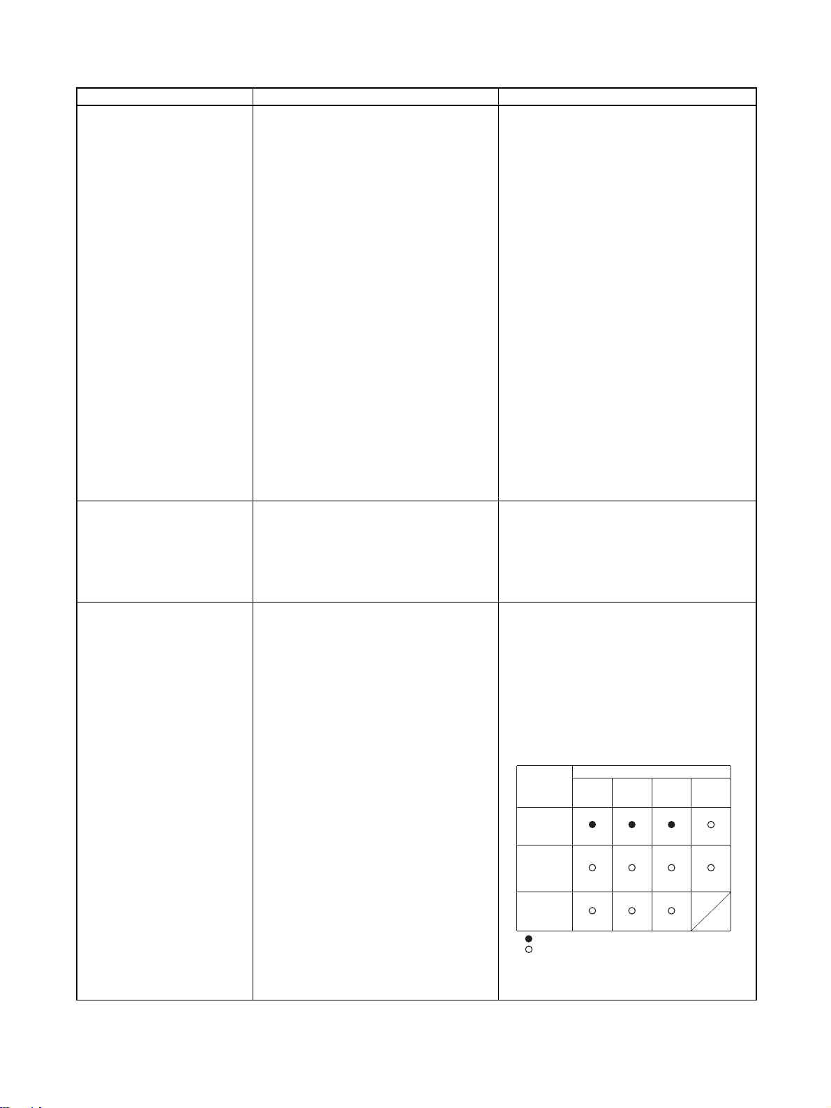
Addition of origin search operation modes
Three origin search operation pattern are
possible by combining the following set-
tings:
• Origin search operations: 3 settings
(Reversal modes 1 and 2, and Singledirection mode)
• Origin detection method: 1 setting
(With origin proximity input signal reversal)
Eleven origin search operation pattern are
possible by combining the following settings:
• Origin search operations: 4 settings
(Reversal modes 1, 2, and 3, and Singledirection mode)
• Origin detection methods: 3 settings (With
origin proximity input signal reversal, Without origin proximity input signal reversal,
Not use origin proximity input signal)
Origin
detection
method
With origin
proximity
input signal
reversal
Without
origin
proximity
input signal
reversal
Not use
origin
proximity
input signal
:
Combinations supported by unit version 1.3 or earlie
:
Combinations supported by unit version 2.0 or later
Note: Origin search operation patterns supported by
absolute encoders.
Origin search operation
Reversal
mode 1
(See note.)
(See note.)
(See note.)
(Refer to 8-2-4 Origin Search Operation.)
Reversal
mode 2
Single-
direction
mode
Reversal
mode 3
xvii
Page 17

Functional upgrade Unit version 1.3 Unit version 2.0
Addition of origin search preset function
The preset function cannot be used during
origin searches.
The preset function can be used during origin searches.
For any of the origin search operations the
present position can be automatically set to
any specified value at the end of the origin
search. When using reversal mode 1 and an
absolute encoder, an offset can also be set
for the absolute origin.
(Refer to 8-2-6 Origin Search Preset and 8-6-
2 Absolute Encoder Operating Procedure.)
Note Changes in Axis Communications Status Flags
The conditions for setting and resetting the Axis Communications Status
Flags in word n+22 of the Common Operating Memory Area have been
changed accompanying the addition of the rejoin function. New conditions are
underlined in the following table.
Functional upgrade Unit version 1.3 or earlier Unit version 2.0 or later
Setting conditions • The flags will turn ON when connections
are made for the axes registered in the
scan list and MECHATROLINK communications start.
Resetting conditions • The flags will remain OFF when MECHA-
TROLINK communications cannot be
started when connections are made for
the axes registered in the scan list.
• The flags will turn OFF if MECHATROLINK communications stop because
the axis is disconnected.
• The flags will turn OFF if a Unit error
occurs that requires disconnection.
• The flags will turn ON when connections
are made for the axes registered in the
scan list and MECHATROLINK communications start.
• The flag will turn ON when the rejoin function is used to start MECHATROLINK communications for an axis registered in the
scan list.
• The flags will remain OFF when MECHATROLINK communications cannot be
started when connections are made for the
axes registered in the scan list.
• The flags will turn OFF if MECHATROLINK
communications stop because the axis is
disconnected.
• The flags will turn OFF if a Unit error occurs
that requires disconnection.
• The flags will turn OFF whenever a communications error occurs after MECHATROLINK communications have been
started for the axis.
With unit version 1.3 or earlier, once MECHATROLINK communications have been started by establishing connections, the Axis Communications Status Flags will not change unless communications
are disconnected (including Unit errors that required disconnection).
With unit version 2.0 or later, the Axis Communications Status Flags will turn OFF after connections
have been established whenever axis operation becomes impossible due to a communications error
(synchronous communications alarm or communications alarm).
Unit Version 2.0 to Unit Version 2.1
Functional upgrade Unit version 2.0 Unit version 2.1
Faster setting of transfer cycle
and communications cycle when
setting the absolute encoder PG
zero point position offset with an
origin search
A longer communications cycle must be
set using the settings given in a separate
table when the absolute encoder PG zero
point position offset is set with an origin
search.
The same communications cycle can be
set regardless of whether the absolute
encoder PG zero point position offset is
set with an origin search.
xviii
Page 18

Read and Understand this Manual
Please read and understand this manual before using the product. Please consult your OMRON
representative if you have any questions or comments.
Warranty and Limitations of Liability
WARRANTY
OMRON's exclusive warranty is that the products are free from defects in materials and workmanship for a
period of one year (or other period if specified) from date of sale by OMRON.
OMRON MAKES NO WARRANTY OR REPRESENTATION, EXPRESS OR IMPLIED, REGARDING NONINFRINGEMENT, MERCHANTABILITY, OR FITNESS FOR PARTICULAR PURPOSE OF THE
PRODUCTS. ANY BUYER OR USER ACKNOWLEDGES THAT THE BUYER OR USER ALONE HAS
DETERMINED THAT THE PRODUCTS WILL SUITABLY MEET THE REQUIREMENTS OF THEIR
INTENDED USE. OMRON DISCLAIMS ALL OTHER WARRANTIES, EXPRESS OR IMPLIED.
LIMITATIONS OF LIABILITY
OMRON SHALL NOT BE RESPONSIBLE FOR SPECIAL, INDIRECT, OR CONSEQUENTIAL DAMAGES,
LOSS OF PROFITS OR COMMERCIAL LOSS IN ANY WAY CONNECTED WITH THE PRODUCTS,
WHETHER SUCH CLAIM IS BASED ON CONTRACT, WARRANTY, NEGLIGENCE, OR STRICT
LIABILITY.
In no event shall the responsibility of OMRON for any act exceed the individual price of the product on which
liability is asserted.
IN NO EVENT SHALL OMRON BE RESPONSIBLE FOR WARRANTY, REPAIR, OR OTHER CLAIMS
REGARDING THE PRODUCTS UNLESS OMRON'S ANALYSIS CONFIRMS THAT THE PRODUCTS
WERE PROPERLY HANDLED, STORED, INSTALLED, AND MAINTAINED AND NOT SUBJECT TO
CONTAMINATION, ABUSE, MISUSE, OR INAPPROPRIATE MODIFICATION OR REPAIR.
xix
Page 19

Application Considerations
SUITABILITY FOR USE
OMRON shall not be responsible for conformity with any standards, codes, or regulations that apply to the
combination of products in the customer's application or use of the products.
At the customer's request, OMRON will provide applicable third party certification documents identifying
ratings and limitations of use that apply to the products. This information by itself is not sufficient for a
complete determination of the suitability of the products in combination with the end product, machine,
system, or other application or use.
The following are some examples of applications for which particular attention must be given. This is not
intended to be an exhaustive list of all possible uses of the products, nor is it intended to imply that the uses
listed may be suitable for the products:
• Outdoor use, uses involving potential chemical contamination or electrical interference, or conditions or
uses not described in this manual.
• Nuclear energy control systems, combustion systems, railroad systems, aviation systems, medical
equipment, amusement machines, vehicles, safety equipment, and installations subject to separate
industry or government regulations.
• Systems, machines, and equipment that could present a risk to life or property.
Please know and observe all prohibitions of use applicable to the products.
NEVER USE THE PRODUCTS FOR AN APPLICATION INVOLVING SERIOUS RISK TO LIFE OR
PROPERTY WITHOUT ENSURING THAT THE SYSTEM AS A WHOLE HAS BEEN DESIGNED TO
ADDRESS THE RISKS, AND THAT THE OMRON PRODUCTS ARE PROPERLY RATED AND INSTALLED
FOR THE INTENDED USE WITHIN THE OVERALL EQUIPMENT OR SYSTEM.
PROGRAMMABLE PRODUCTS
OMRON shall not be responsible for the user's programming of a programmable product, or any
consequence thereof.
xx
Page 20

Disclaimers
CHANGE IN SPECIFICATIONS
Product specifications and accessories may be changed at any time based on improvements and other
reasons.
It is our practice to change model numbers when published ratings or features are changed, or when
significant construction changes are made. However, some specifications of the products may be changed
without any notice. When in doubt, special model numbers may be assigned to fix or establish key
specifications for your application on your request. Please consult with your OMRON representative at any
time to confirm actual specifications of purchased products.
DIMENSIONS AND WEIGHTS
Dimensions and weights are nominal and are not to be used for manufacturing purposes, even when
tolerances are shown.
PERFORMANCE DATA
Performance data given in this manual is provided as a guide for the user in determining suitability and does
not constitute a warranty. It may represent the result of OMRON's test conditions, and the users must
correlate it to actual application requirements. Actual performance is subject to the OMRON Warranty and
Limitations of Liability.
ERRORS AND OMISSIONS
The information in this manual has been carefully checked and is believed to be accurate; however, no
responsibility is assumed for clerical, typographical, or proofreading errors, or omissions.
xxi
Page 21

xxii
Page 22

PRECAUTIONS
This section provides general precautions for using the Position Control Unit and related devices.
The information contained in this section is important for the safe and reliable application of Position Control Units. You
must read this section and understand the information contained before attempting to set up or operate a Position Control
Unit.
1 Intended Audience . . . . . . . . . . . . . . . . . . . . . . . . . . . . . . . . . . . . . . . . . . . . . xxiv
2 General Precautions . . . . . . . . . . . . . . . . . . . . . . . . . . . . . . . . . . . . . . . . . . . . xxiv
3 Safety Precautions. . . . . . . . . . . . . . . . . . . . . . . . . . . . . . . . . . . . . . . . . . . . . . xxiv
4 Operating Environment Precautions . . . . . . . . . . . . . . . . . . . . . . . . . . . . . . . . xxv
5 Application Precautions . . . . . . . . . . . . . . . . . . . . . . . . . . . . . . . . . . . . . . . . . xxvi
6 Conformance to EC Directives . . . . . . . . . . . . . . . . . . . . . . . . . . . . . . . . . . . . xxviii
6-1 Applicable Directives . . . . . . . . . . . . . . . . . . . . . . . . . . . . . . . . . . . . xxviii
6-2 Concepts . . . . . . . . . . . . . . . . . . . . . . . . . . . . . . . . . . . . . . . . . . . . . . xxviii
6-3 Conformance to EC Directives . . . . . . . . . . . . . . . . . . . . . . . . . . . . . xxviii
6-4 Installation within Control Panels . . . . . . . . . . . . . . . . . . . . . . . . . . xxviii
xxiii
Page 23

Intended Audience 1
1 Intended Audience
This manual is intended for the following personnel, who must also have
knowledge of electrical systems (an electrical engineer or the equivalent).
• Personnel in charge of installing FA systems.
• Personnel in charge of designing FA systems.
• Personnel in charge of managing FA systems and facilities.
2 General Precautions
The user must operate the product according to the performance specifications described in the operation manuals.
Before using the product under conditions which are not described in the
manual or applying the product to nuclear control systems, railroad systems,
aviation systems, vehicles, combustion systems, medical equipment, amusement machines, safety equipment, and other systems, machines, and equipment that may have a serious influence on lives and property if used
improperly, consult your OMRON representative.
Make sure that the ratings and performance characteristics of the product are
sufficient for the systems, machines, and equipment, and be sure to provide
the systems, machines, and equipment with double safety mechanisms.
This manual provides information for programming and operating the Unit. Be
sure to read this manual before attempting to use the Unit and keep this manual close at hand for reference during operation.
!WARNING It is extremely important that a Position Control Units and related devices be
used for the specified purpose and under the specified conditions, especially
in applications that can directly or indirectly affect human life. You must consult with your OMRON representative before applying Position Control Units
and related devices to the above-mentioned applications.
3 Safety Precautions
!WARNING Do not attempt to take any Unit apart while the power is being supplied. Doing
so may result in electric shock.
!WARNING Do not attempt to disassemble, repair, or modify any Units. Any attempt to do
so may result in malfunction, fire, or electric shock.
!WARNING Never touch any of the terminals while power is being supplied. Doing so may
result in serious electric shock.
!WARNING Provide safety measures in external circuits (i.e., not in the Programmable
Controller or Position Control Unit) to ensure safety in the system if an abnormality occurs due to malfunction of the PLC, malfunction of the PCU (Position
Control Unit), or external factors affecting the operation of the PLC or PCU.
Not providing sufficient safety measures may result in serious accidents.
xxiv
Page 24

Operating Environment Precautions 4
• Emergency stop circuits, interlock circuits, limit circuits, and similar safety
measures must be provided in external control circuits.
• The PLC will turn OFF all outputs when its self-diagnosis function detects
any error or when a severe failure alarm (FALS) instruction is executed.
As a countermeasure for such errors, external safety measures must be
provided to ensure safety in the system.
• The PLC or PCU outputs may remain ON or OFF due to deposits on or
burning of the output relays, or destruction of the output transistors. As a
countermeasure for such problems, external safety measures must be
provided to ensure safety in the system.
• When the 24-V DC output (service power supply to the PLC) is overloaded or short-circuited, the voltage may drop and result in the outputs
being turned OFF. As a countermeasure for such problems, external
safety measures must be provided to ensure safety in the system.
• External safety measures must also be taken to ensure safety in the event
of unexpected operation when connecting or disconnecting the PCU’s
connectors.
!Caution Execute online editing only after confirming that no adverse effects will be
caused by extending the cycle time. Otherwise, the input signals may not be
readable.
!Caution Confirm safety at the destination node before transferring a program to
another node or changing contents of the I/O memory area. Doing either of
these without confirming safety may result in injury.
4 Operating Environment Precautions
!Caution Do not operate the control system in the following locations:
• Locations subject to direct sunlight.
• Locations subject to temperatures or humidity outside the range specified
in the specifications.
• Locations subject to condensation as the result of severe changes in temperature.
• Locations subject to corrosive or flammable gases.
• Locations subject to dust (especially iron dust) or salts.
• Locations subject to exposure to water, oil, or chemicals.
• Locations subject to shock or vibration.
!Caution Take appropriate and sufficient countermeasures when installing systems in
the following locations:
• Locations subject to static electricity or other forms of noise.
• Locations subject to strong electromagnetic fields.
• Locations subject to possible exposure to radioactivity.
• Locations close to power supplies.
xxv
Page 25

Application Precautions 5
!Caution The operating environment of the PLC System can have a large effect on the
longevity and reliability of the system. Improper operating environments can
lead to malfunction, failure, and other unforeseeable problems with the PLC
System. Make sure that the operating environment is within the specified conditions at installation and remains within the specified conditions during the
life of the system.
5 Application Precautions
Observe the following precautions when using the PLC System.
!WARNING Always heed these precautions. Failure to abide by the following precautions
could lead to serious or possibly fatal injury.
• Always connect to a ground of 100
connecting to a ground of 100
• Always turn OFF the power supply to the PLC before attempting any of
the following. Not turning OFF the power supply may result in malfunction
or electric shock.
• Mounting or dismounting Power Supply Units, I/O Units, CPU Units, Inner Boards, or any other Units.
• Assembling the Units.
• Setting DIP switches or rotary switches.
• Connecting cables or wiring the system.
• Connecting or disconnecting the connectors.
!Caution Failure to abide by the following precautions could lead to faulty operation of
the PLC, the PCU, or the system, or could damage the PLC or PCU. Always
heed these precautions.
• Fail-safe measures must be taken by the customer to ensure safety in the
event of incorrect, missing, or abnormal signals caused by broken signal
lines, momentary power interruptions, or other causes. Not doing so may
cause malfunction resulting in serious injury.
• Interlock circuits, limit circuits, and similar safety measures in external circuits (i.e., not in the Programmable Controller) must be provided by the
customer.
• Install external breakers and take other safety measures against short-circuiting in external wiring. Insufficient safety measures against short-circuiting may result in burning.
• For CS-series PLCs, always tighten the mounting screw at the bottom of
the PCU to a torque of 0.4 N
• For CJ-series PLCs, lock the sliders securely until they click into place
when connecting the Power Supply Unit, CPU Unit, I/O Units, Special I/O
Units, or CPU Bus Units. Functions may not work correctly if the sliders
are not locked properly.
• Always attach the End Cover provided with the CPU Unit to the Unit on
the right end of the PLC. The CJ-series PLC will not operate properly if
the End Cover is not attached.
Ω or less when installing the Units. Not
Ω or less may result in electric shock.
⋅m.
xxvi
Page 26

Application Precautions 5
• Take appropriate measures to ensure that the specified power with the
rated voltage and frequency is supplied in places where the power supply
is unstable. An incorrect power supply may result in malfunction.
• Remove the label after the completion of wiring to ensure proper heat dissipation. Leaving the label attached may result in malfunction.
• Disconnect the LG (line ground) terminal and GR (ground) terminal before
performing withstand voltage and insulation resistance tests.
• Confirm that set parameters and data operate properly.
• Perform wiring according to specified procedures.
• Double-check all wiring and switch settings before turning ON the power
supply. Incorrect wiring may result in burning.
• Check the user program for proper execution before actually running it on
the Unit. Not checking the program may result in unexpected operation.
• Confirm that no adverse effect will occur in the system before attempting
any of the following. Not doing so may result in an unexpected operation.
• Changing the operating mode of the PLC (including setting the Startup
Mode).
• Force-setting/force-resetting any bit in memory.
• Changing the present value of any word or any set value in memory.
• After replacing Units, resume operation only after transferring to the new
CPU Unit, Special I/O Units, CPU Bus Units, and externally connected
devices the contents of the DM Area, Holding Area, and other data
required for resuming operation. Not doing so may result in an unexpected operation.
• Do not pull on the cables or bend the cables beyond their natural limit.
Doing either of these may break the cables.
• Do not place objects on top of the cables or other wiring lines. Doing so
may break the cables.
• Before touching a Unit, be sure to first touch a grounded metallic object in
order to discharge any static build-up. Not doing so may result in malfunction or damage.
• Never turn OFF the power to the Unit while transferring data.
xxvii
Page 27

Conformance to EC Directives 6
6 Conformance to EC Directives
6-1 Applicable Directives
•EMC Directives
6-2 Concepts
EMC Directives
OMRON devices that comply with EC Directives also conform to the related
EMC standards so that they can be more easily built into other devices or the
overall machine. The actual products have been checked for conformity to
EMC standards (see the following note). Whether the products conform to the
standards in the system used by the customer, however, must be checked by
the customer.
EMC-related performance of the OMRON devices that comply with EC Directives will vary depending on the configuration, wiring, and other conditions of
the equipment or control panel on which the OMRON devices are installed.
The customer must, therefore, perform the final check to confirm that devices
and the overall machine conform to EMC standards.
Note Applicable EMC (Electromagnetic Compatibility) standards are as follows:
EMS (Electromagnetic Susceptibility): EN61000-6-2
EMI (Electromagnetic Interference): EN61000-6-4
6-3 Conformance to EC Directives
The PCUs comply with EC Directives. To ensure that the machine or device in
which a PCU is used complies with EC Directives, the PCU must be installed
as follows:
1,2,3... 1. The PCU is defined as a in-panel device and must be installed within a
control panel.
2. Reinforced insulation or double insulation must be used for the DC power
supplies used for I/O.
3. PCUs complying with EC directives also meet the common emission standard (EN61000-6-4). The measures required to ensure that the standard
is met will vary with the overall configuration of the control panel, the other
devices connected to the control panel, wiring, and other conditions. The
customer must therefore confirm that EC directives are met for the overall
machine or device, particularly for the radiated emission requirement
(10 m).
6-4 Installation within Control Panels
Unnecessary clearance in cable inlet or outlet ports, operation panel mounting holes, or in the control panel door may cause electromagnetic wave leakage or interference. In this case, the product may fail to meet EC Directives. In
order to prevent such interference, fill clearances in the control panel with conductive packing. (In places where conductive packing comes in contact with
the control panel, ensure electrical conductivity by removing the paint coating
or masking these parts when painting.)
(Radiated emission: 10-m regulations)
xxviii
Page 28

SECTION 1
Features and System Configuration
This section introduces the features of the Position Control Unit, explains the system configuration in which it is used, and
also provides information on basic operations, functions and specifications.
1-1 Features . . . . . . . . . . . . . . . . . . . . . . . . . . . . . . . . . . . . . . . . . . . . . . . . . . . . . . 2
1-2 System Configuration . . . . . . . . . . . . . . . . . . . . . . . . . . . . . . . . . . . . . . . . . . . 3
1-3 Basic Operations . . . . . . . . . . . . . . . . . . . . . . . . . . . . . . . . . . . . . . . . . . . . . . . 4
1-3-1 Position Control (Direct Operation) . . . . . . . . . . . . . . . . . . . . . . . . . 4
1-3-2 Speed Control and Torque Control . . . . . . . . . . . . . . . . . . . . . . . . . . 5
1-3-3 Other Operations. . . . . . . . . . . . . . . . . . . . . . . . . . . . . . . . . . . . . . . . 5
1-4 List of Functions and Specifications. . . . . . . . . . . . . . . . . . . . . . . . . . . . . . . . 6
1-4-1 General Specifications . . . . . . . . . . . . . . . . . . . . . . . . . . . . . . . . . . . 6
1-4-2 List of Functions and Specifications. . . . . . . . . . . . . . . . . . . . . . . . . 6
1-5 List of Functions by Purpose . . . . . . . . . . . . . . . . . . . . . . . . . . . . . . . . . . . . . 8
1-6 Comparison with Existing Models . . . . . . . . . . . . . . . . . . . . . . . . . . . . . . . . . 9
1
Page 29
Fe at ur e s Section 1-1
9
8
5
4
3
2
1
0
1-1 Features
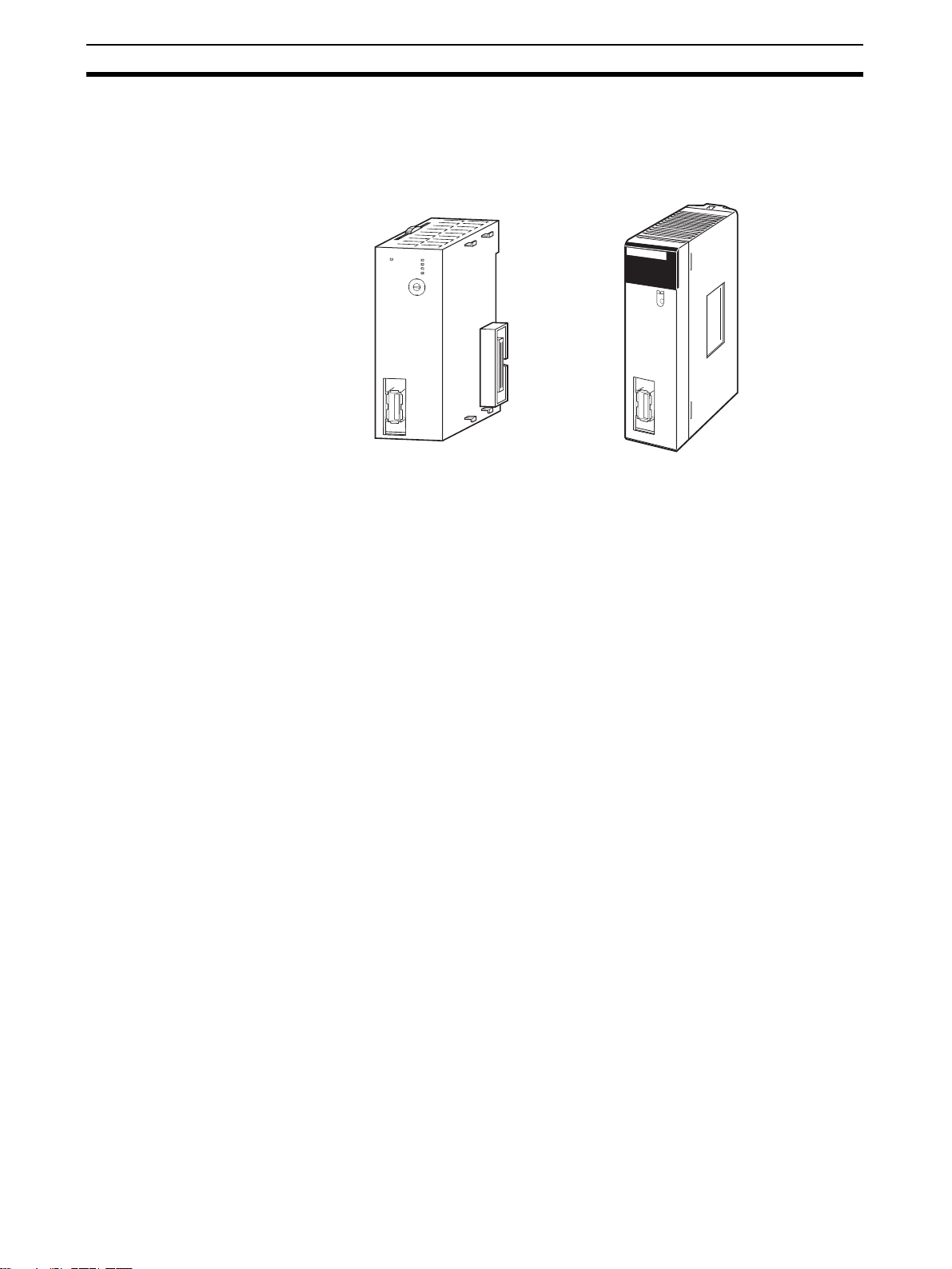
Position Control Unit
CJ1W-NC271/471/F71 CS1W-NC271/471/F71
Compatible with the
MECHATROLINK-II Highspeed Field Network
High-speed, Highprecision Control Using
Data Communications
N
C
F71
M
L
K
R
U
N
E
R
C
E
R
H
E
R
M
D
C
E
B
U
N
F
IT
A
0
9
1
8
No.
2
7
3
6
4
5
M
LK
NCF71
RUN
ERC
UNIT
No.
ERH
ERM
MLK
CS
M
L
K
The Position Control Unit is a CS/CJ-series CPU Bus Unit. The Position Control Unit (PCU) receives commands from the CPU Unit's internal Auxiliary
Area and outputs positioning commands to MECHATROLINK-II Servo Drives.
MECHATROLINK is a registered trademark of MECHATROLINK Members
Association.
A MECHATROLINK-II high-speed (10 Mbps) communications interface is
used to control Servo Drives for up to 16 axes with a single CS/CJ-series Unit.
Shielded twisted-pair cables in daisy-chain formation make wiring simple and
enable multi-axis systems that require less wiring and are smaller in size.
Optimal motor performance can be achieved by transmitting data using communications between the Programmable Controller (PLC) and Servo Drives,
without having to set an upper limit for the designated speed. High-speed and
high-precision position control using high-resolution motors are possible.
Position Control (Direct
Operation)
Speed Control and Torque
Control
Compatible with
Servomotors with
Absolute Encoders
Transfer Data between
Host PLC and Servo Drive
2
Positioning can be performed simply by directly setting the target position and
target speed from the CPU Unit. Positioning to either absolute or relative positions is also possible. Interrupt feeding is also supported. With interrupt feeding, positioning is continued for a specified amount after an interrupt input
signal is received, and then the axis is stopped.
The Servo Drive's speed and torque can be controlled by directly specifying
the target speed and torque from the CPU Unit.
The PCU is compatible with Servomotors that have absolute encoders. Using
such Servomotors eliminates the need to repeatedly perform origin searches.
The Servo Drive's parameters and monitors can be set from the CPU Unit. All
the data for the multi-axis system can be centrally controlled from the host
PLC. This removes the difficulty in starting up devices or setting data when
replacing a Unit.
Page 30
System Configuration Section 1-2
1-2 System Configuration
The PCU receives commands from the CPU Unit's ladder program and control signal status (forward/reverse rotation limit, origin, origin proximity, and
interrupt input signals) from devices connected externally to the Servo Drive,
and uses them to control Servo Drive positioning.
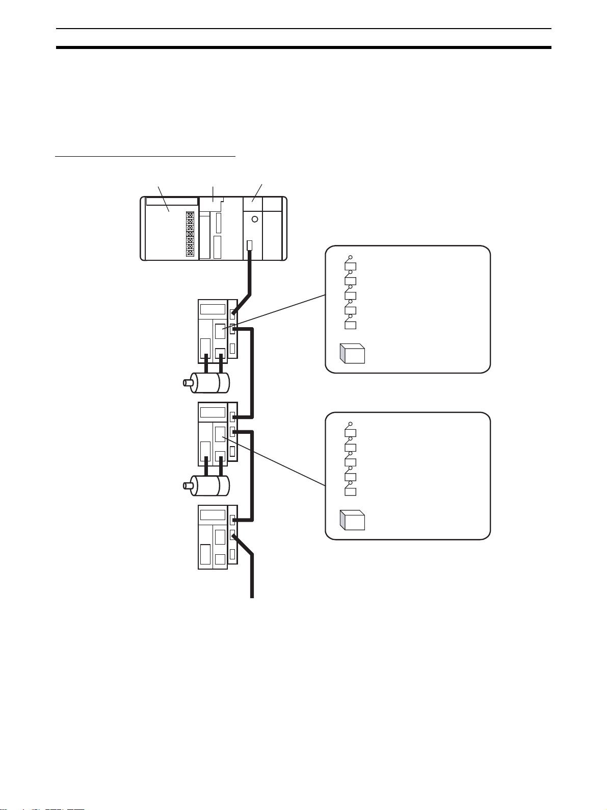
System Configuration Example
Power Supply Unit
Servo Drive
Servomotor
Servo Drive
Servomotor
Servo Drive
CJ-series
CPU Unit
CJ1W-NCF71
Position Control Unit
External inputs
Forward rotation limit input signal
Reverse rotation limit input signal
Origin input signal
Origin proximity input signal
Interrupt input signal
Etc.
24-V DC power supply
for interface
External inputs
Forward rotation limit input signal
Reverse rotation limit input signal
Origin input signal
Origin proximity input signal
Interrupt input signal
Etc.
24-V DC power supply
for interface
MECHATROLINK-II
(16 axes max.)
3
Page 31

Basic Operations Section 1-3
1-3 Basic Operations
The PCU's operations are as follows:
CJ1W-NC@71/CS1W-NC@71
Position Control Unit functions
Position control
(direct operation)
Speed control
Torque control
Other operations
1-3-1 Position Control (Direct Operation)
Positioning can be executed either to an absolute position (i.e., to an absolute
position from the origin) or to an incremental position (i.e., to a position relative to the present position). Interrupt feeding is also possible, whereby an
axis is moved a specified amount when an interrupt input signal is received
and then stopped.
Absolute movement
Relative movement
Interrupt feeding
Origin searches
Jogging
Overrides
Present position preset
Stop functions
Backlash compensation
Absolute Movements and
Relative Movements
Speed
Start
With absolute and relative movements, position and speed data are set
directly from the ladder program in the CPU Unit. Positioning is executed
according to operating commands sent to the PCU from the CPU Unit. It is
also possible to change the speed or to send commands to move axes to different positions while positioning is being performed.
Y
New target position
Target position before
position changed
Position changed, start
Time
Speed changed
Start
X
4
Page 32

Basic Operations Section 1-3
Interrupt Feeding When an interrupt input signal is received, positioning is continued for the
specified amount of movement and then stopped.
Speed
Interrupt input
Specified amount of movement (a
negative direction can also be set)
Time
Linear Interpolation Linear interpolation can be performed for a combination of axes (Unit Ver. 1.1
or later).
1-3-2 Speed Control and Torque Control
Speed command data and torque command data are set from the CPU Unit.
Speed control and torque control of the Servomotor are executed by sending
operating commands to the PCU from the CPU Unit.
1-3-3 Other Operations
Origin Searches The origin search operations find the origin for a designated axis.
Jogging Jogging moves a specified axis at a designated speed and then stops it.
Overrides When an override is enabled during positioning, the target speed is changed
to the override speed.
Override set value: 150%
Time
Present Position Preset
(Changing the Present
Speed
× 1.5
A
A
Override Enable Bit
1
0
The PRESENT POSITION PRESET command changes the present position
to a specified position.
Position)
Stop Functions The DECELERATION STOP command decelerates positioning to a stop.
The EMERGENCY STOP command cancels operating commands immediately and stops the axis after moving it for the number of pulses remaining in
the Servo Drive's deviation counter.
5
Page 33

List of Functions and Specifications Section 1-4
1-4 List of Functions and Specifications
1-4-1 General Specifications
Item Specification
Model CJ1W-NC271/471/F71 CS1W-NC271/471/F71
Internal current
consumption
Dimensions 31 × 90 × 65 mm (W × H × D) 130 × 35 × 101 mm (W × H × D)
Weight 95 g max. 188 g max.
Ambient operat-
ing temperature
Approved stan-
dards
Specifications not listed above conform to general CS/CJ Series specifications.
1-4-2 List of Functions and Specifications
Item Specification
Unit classification CPU Bus Unit
Applicable PLCs CS/CJ Series
Possible unit number settings 0 to F
I/O allocations Common Operating Memory Area Words allocated in CPU Bus Unit Area: 25 words (15 output words,
Axis Operating Memory Area Allocated in one of the following areas (user-specified):
Compatible devices • OMRON G-series Servo Drives
Control method Control commands executed using MECHATROLINK-II synchro-
Maximum number of controlled axes CS1W/CJ1W-NC271: 2 axes, CS1W/CJ1W-NC471: 4 axes,
Control units Position command unit Command unit: Depends on the Electronic Gear Setting in the
Speed command unit for position
control
Acceleration/deceleration speeds
for position control
Speed command unit for speed
control
Torque command unit for torque
control
360 mA max. at 5 V DC
0 to 55°C
CE, cULus, and C-tick
10 input words)
CIO, Work, Auxiliary, Holding, DM, or EM Area.
Number of words allocated: 50 words (25 output words, 25 input
words) × Highest axis No. used
(Built-in MECHATROLINK-II communications)
• OMRON W-series Servo Drives
(equipped with MECHATROLINK-II Application Module or built-in
MECHATROLINK-II communications)
• OMRON SMARTSTEP Junior Servo Drives
(Built-in MECHATROLINK-II communications)
Note SMARTSTEP Junior Servo Drive are supported by Position
Control Units with unit version 2.0 or later.
nous communications.
CS1W/CJ1W-NCF71: 16 axes
Servo Parameters.
Default setting: Pulses
Command units/s
2
10,000 command units/s
0.001% of the motor's momentary maximum rotation speed
0.001% of the motor's momentary maximum torque
6
Page 34

List of Functions and Specifications Section 1-4
Item Specification
Control command range
Control functions
Auxiliary functions
External I/O Position Control Unit One MECHATROLINK-II interface port
Position command range −2,147,483,648 to 2,147,483,647 (command units)
Speed command range for position
control
Acceleration/deceleration speeds
for position control
Speed command range for speed
control
Torque command range for torque
control
Servo lock/unlock Creates (Servo lock) or releases (Servo unlock) the position loop
Position control Positions to an absolute position or relative position according to
Origin determination • Origin search: Establishes the origin using the specified search
Jogging Outputs pulses at a fixed speed in the forward rotation or reverse
Interrupt feeding Performs positioning by moving the axis a fixed amount when an
Speed control Performs speed control by sending a command to the Servo Drive
Torque control Performs torque control by sending a command to the Servo Drive
Stop functions • Deceleration stop: Decelerates the moving axis to a stop.
Acceleration/deceleration curves Sets one of the following: a trapezoidal (linear) curve, an exponen-
Torque limit Restricts the output torque during axis operation.
Override Multiplies the axis command speed by a specified ratio.
Servo parameter transfer Reads and writes the Servo Drive parameters from the ladder pro-
Monitoring function Monitors the control status of the Servo Drive, such as the com-
Software limits Limits software operation within the positioning range during posi-
Backlash compensation Compensates for the amount of play in the mechanical system
Deviation counter reset The position deviation in the Servo Drive’s deviation counter can
Servo Drive I/O Forward/reverse rotation limit inputs, origin proximity inputs, exter-
0 to 2,147,483,647 (command units/s)
2
1 to 65,535 (10,000 command units/s
−199.999% to 199.999%
The upper limit of the speed command range depends on the
specifications of the Servo Drive.
−199.999% to 199.999%
The upper limit of the torque command range depends on the
specifications of the Servo Drive.
on the PCU.
the target position and target speed specified from the ladder program.
method.
• Present position preset: Changes the present position to a speci-
fied position to establish the origin.
• Origin return: Returns the axis from any position to the estab-
lished origin.
• Absolute encoder origin: Establishes the origin using a Servomo-
tor that has an absolute encoder, without having to use an origin
search.
rotation direction.
external interrupt input is received while the axis is moving.
speed loop.
current loop.
• Emergency stop: Positions the moving axis for the number of
pulses remaining in the deviation counter and then stops the axis.
tial curve, or an S-curve (moving average).
Override: 0.01% to 327.67%
gram in the CPU Unit.
mand coordinate positions, feedback position, current speed, and
torque.
tion control.
according to a set value.
be reset to 0 (unit version 1.3 or later).
nal interrupt inputs 1 to 3 (can be used as external origin inputs)
)
7
Page 35

List of Functions by Purpose Section 1-5
Item Specification
Self-diagnostic functions Watchdog, flash memory check, memory corruption check
Error detection functions Overtravel, Servo Drive alarm detection, CPU error, MECHA-
TROLINK communications error, Unit setting error
1-5 List of Functions by Purpose
Purpose Category Name Basic function Details
Establishing the
mechanical origin of
the machine
Point-to-point (PTP)
positioning
Changing the target
position and speed
as required during
positioning
Performing positioning for a specified
distance from an
external input point
during positioning
Performing manual
feeding for adjustment or other purpose
Reducing shock
while device is operating
Temporarily multiplying the machine's
operating speed by a
constant ratio to perform startup adjustments
Restricting output
torque during control operations such
as pushing control
Stopping the device
during operation
Changing the Servo
Drive settings from
the PLC
Origin determination
Position control
Auxiliary
functions
Stop function
Data transfer
function
Origin search The motor is operated to estab-
Present position preset The position where the motor is
Origin return The axis is returned to the estab-
Absolute encoder origin The origin is established using a
Direct operation (absolute movement or relative
movement)
Direct operation:
Changing target position
or changing target speed
Interrupt feeding When an interrupt input signal
Jogging The axis is moved at a fixed
Acceleration/deceleration curves
Overrides The axis command speed is mul-
Torque limit A constant limit is applied to the
Deceleration stop or
emergency stop
Reading/writing Servo
parameters
lished the origin.
stopped is set to a specified position to establish the origin.
lished origin.
Servomotor with an absolute
encoder, so origin searches are
not required at machine startup.
The position and speed are specified to perform positioning using
an absolute or relative movement.
The target position or target
speed is changed during positioning with direct operation.
turns ON during positioning with
direct operation, operation
switches to positioning for a fixed
amount.
speed in the forward rotation or
reverse rotation direction.
Acceleration/deceleration is performed according to the basic
trapezoidal curve (linear acceleration/deceleration), an exponential
curve, or an S-curve, which
greatly helps to reduce mechanical vibration.
tiplied by a constant ratio.
output torque of the Servomotor
during positioning.
The moving axis is decelerated to
a stop or the axis is moved for the
number of pulses remaining in the
deviation counter and then
stopped.
Servo Drive parameters are read
or written from the CPU Unit.
8-2 Origin Search
Operation
8-3 Present Position
Preset
8-4 Origin Return
8-6 Absolute
Encoder Origin
9-4 Using Direct
Operation
9-4-3 Changing Target Position
9-4-4 Changing Target Speed
9-5 Interrupt Feeding
10-2 Jogging
7-4 Acceleration and
Deceleration Operations
10-3 Override
10-4 Torque Limits
10-9 Stop Functions
5-3 Transferring
Servo Parameters
8
Page 36

Comparison with Existing Models Section 1-6
Purpose Category Name Basic function Details
Performing speed
feeding in rotary control such as sheet
feeding.
Changing the output
torque sequentially
during control operations such as tightening.
Speed control
Torque control
Speed control The speed command value is
directly specified to control the
Servomotor rotation.
Torque control The torque command value is
directly specified to control the
Servomotor's output torque.
10-5 Speed Control
10-6 Torque Control
1-6 Comparison with Existing Models
Functions and
performance
Unit type CPU Bus Unit Special I/O Unit
Unit number alloca-
tion
Control method Commands are executed using MECHA-
Format of data
exchanged between
PLC and PCU
Position command
range
Present position
range
Zone range No zone functions −1,073,741,823 to 1,073,741,823 pulses
Speed command
range
Torque command
range
Overrides 0.01% to 327.67% in increments of 0.01% 1% to 999% in increments of 1%
Memory operation
function
Unit numbers can be set from 0 to F
(CPU Bus Units).
TROLINK-II synchronous communications.
Binary (hexadecimal)
Example: Present position is output to the PLC
in 32-bit signed binary format.
−2,147,483,648 to 2,147,483,647
(Unit depends on Servo Parameters)
−2,147,483,648~2,147,483,647
(Unit depends on Servo parameters)
Position control:
0 to 2,147,483,647 (command units/s)
(Upper limit speed depends on Servo Drive
and Servomotor.)
Speed control:
−199.999% to 199.999%
(percentage of Servomotor’s momentary maximum rotation speed)
The upper limit of the speed command range
depends on the specifications of the Servo
Drive.
−199.999% to 199.999%
(percentage of Servomotor's momentary maximum torque)
The upper limit of the torque command range
depends on the specifications of the Servo
Drive.
None Absolute/relative movement, linear interpolation,
CJ1W-NC@71
CS1W-NC@71
CJ1W-NC@13/@33
CS1W-NC@13/@33
Unit numbers can be set from 0 to 95.
• One-axis and two-axis PCUs: One unit number
used.
• Four-axis PCUs: Two unit numbers used.
Open-loop control is performed using a pulse
train output.
Same as CJ1W-NC@71/CS1W-NC@71.
−1,073,741,823 to 1,073,741,823 pulses
−2,147,483,647 to 2,147,483,647 pulses
1 to 500,000 (unit: 1 pps)
None
interrupt feeding, speed control, forced interrupt,
and teaching
9
Page 37

Comparison with Existing Models Section 1-6
Functions and
performance
Origin search Origin search method:
• The origin input signal is detected after the origin proximity input signal turns OFF.
• The origin input signal is detected after the origin proximity input signal turns ON. (Unit version 2.0 or later)
• The origin input signal is detected without
using the origin proximity input signal. (Unit
version 2.0 or later)
Origin compensation: After detecting the origin
input signal, positioning is performed for the origin return final travel distance (specified in Servo
Parameters).
Acceleration/deceleration curves
Setting acceleration/
deceleration speeds
Deviation counter
reset
Emergency stop A hardware input contact is not provided on the
Data transfer method Writes/reads using the Data Transfer Bit. • Data can be read or written using the Data
Saving data Parameters can be saved to the flash memory in
CPU Unit cycle time
extension for END
refresh
Response time 4 ms max. (time from when the start commands
Trapezoidal curve, exponential curve, or S-curve
S-curve acceleration/deceleration uses a moving average.
Accelerations and decelerations are specified in
units of 10,000 command units/s
eters are set individually for each axis.
Supported (unit version 1.3 or later). Supported.
Position Control Unit.
Stopping is possible after moving the number of
pulses remaining in the deviation counter by
using an allocated operation bit.
the PCU.
Servo Parameters are saved in the Servo Drive.
1 ms max. per 16 axes (using the CS1/CJ1-H
CPU Unit)
for the ladder program are sent until the Servo
Drive receives the control command when four
axes are connected) (See note.)
CJ1W-NC@71
CS1W-NC@71
2
. Servo param-
CJ1W-NC@13/@33
CS1W-NC@13/@33
Origin search methods:
• The origin input signal is detected after the origin proximity input signal turns ON.
• The origin input signal is detected after the origin proximity input signal turns OFF.
• The origin input signal is detected without
using the origin proximity input signal.
Origin compensation: The axis is moved for the
amount specified by the origin compensation
data (specified from the Unit) at the proximity
speed.
Trapezoidal curve or S-curve
S-curve acceleration/deceleration uses a tertiary function.
The times in milliseconds required to reach the
maximum speed from the initial speed and to
reach the initial speed from the maximum speed
are specified
Direct operation: Acceleration/deceleration
speeds are specified as operation data from the
PLC.
Memory operation: Up to 9 acceleration/deceleration speeds per axis are recorded in the Unit.
The PCU's hardware input contact is used.
Transfer Bit.
• Data can be read or written using the IOWR/
IORD instruction.
Axis Parameters and Zone Data are saved in the
flash memory in the PCU.
0.5 ms max. per PCU
4 ms max. (time from when the start commands
for the ladder program are sent until the Position
Control Unit performs pulse output when all axes
of a four-axis Unit are being operated simultaneously)
10
Note The response time depends on the cycle time of the PLC and the MECHA-
TROLINK communications settings. The time shown in the table is the maximum value obtained when calculated according to specified measurement
conditions. For details, refer to Appendix A Performance Characteristics.
Page 38

Basic Procedures
This section provides an overview of the procedures required to use the Position Control Unit.
2-1 Basic Flow of Operations . . . . . . . . . . . . . . . . . . . . . . . . . . . . . . . . . . . . . . . . 12
2-2 Starting Operation . . . . . . . . . . . . . . . . . . . . . . . . . . . . . . . . . . . . . . . . . . . . . . 16
2-2-1 Overview of Operation . . . . . . . . . . . . . . . . . . . . . . . . . . . . . . . . . . . 16
2-2-2 System Configuration and Wiring . . . . . . . . . . . . . . . . . . . . . . . . . . 16
2-2-3 Setting the PCU . . . . . . . . . . . . . . . . . . . . . . . . . . . . . . . . . . . . . . . . 18
2-2-4 Starting MECHATROLINK Communications. . . . . . . . . . . . . . . . . 21
2-2-5 Setting Servo Parameters . . . . . . . . . . . . . . . . . . . . . . . . . . . . . . . . . 22
2-2-6 Operating the Servomotor from the PCU . . . . . . . . . . . . . . . . . . . . . 25
SECTION 2
11
Page 39

Basic Flow of Operations Section 2-1
2-1 Basic Flow of Operations
The basic flow of Position Control Unit (PCU) operation is described in this
section. The steps from installation through setting the MECHATROLINK
devices are required only when installing the devices for the first time. When
PCU and MECHATROLINK device settings have been completed, start operation from starting MECHATROLINK communications in the flow of operation.
Flow of operation Details
START
Install the PCU.
Installation
Set the unit number of the PCU.
Set the station addresses of the Servo Drives.
Connect the Servomotors to the Servo Drives.
Connect the Servo Drives to the external input
devices.
Wiring
Connect the Servo Drives to the PCU.
Turn ON the power to the PLC.
Create the I/O tables for the PLC.
PLC Settings
Transfer the common parameters from the CPU
Unit to the PCU using the WRITE DATA Bit in
the Common Operating Memory Area.
Transfer the axis parameters from the CPU Unit
to the PCU using the WRITE DATA Bit in the
Common Operating Memory Area.
Transfer only the axis parameters
for the axes to be used.
Save the transferred common parameters and
PCU Settings
axis parameters to the PCU's flash memory
using the SAVE DATA Bit in the PCU's
Common Operating Memory Area.
3-2 Installing the Position
Control Unit
3-1 Nomenclature and
Functions
(See note 1.)
(See note 1.)
3-3 External I/O Circuits
3-4 Wiring
(See note 2.)
4-3 Common Parameter Area
4-6 Common Operating
Memory Area
5-2-1 Writing PCU
Parameters
4-4 Axis Parameter Area
5-2-1 Writing PCU
Parameters
5-2-3 Saving PCU
Parameters
12
Restart the PCU or cycle the power to the PLC.
The PCU can now communicate
with MECHATROLINK devices.
(Continued on next page.)
Note (1) Perform wiring according to instructions given in the Servomotor and Ser-
vo Drive's operation manuals.
(2) Refer to the CJ Series PLC Operation Manual.
Page 40

Basic Flow of Operations Section 2-1
Flow of operation Details
(Continued from previous page.)
Turn ON the power to the Servo Drives.
Turn ON the CONNECT Bit in the PCU's
Common Operating Memory Area.
Check that communications are established with
the connected devices by referring to the axis
communications status in the PCU's Common
Operating Memory Area.
Are communications established
with all devices?
Starting MECHATROLINK communications (setup)
Transfer the Servo parameters from the CPU
Unit to the PCU using the WRITE SERVO PARAMETER Bit and SAVE SERVO PARAMETER
Bit in the PCU's Axis Operating Memory Areas.
Use either of the following methods to enable
the parameter settings for offline parameters.
1) Perform the device setup.
2) Turn OFF the CONNECT Bit (releases the
connection) in the PCU's Common Operating
Memory Area, and after Servo
communications have stopped, cycle the
Setting the MECHATROLINK devices
Servo Drive power.
YES
The MECHATROLINK devices can
now be operated from the PCU.
Transfer (save) only the Servo
Parameters for the axes to be used.
The Servo Parameters that have
been set are now enabled.
NO
4-6 Common Operating
Memory Area
6-3-1 Establishing
Connections
6-3-2 MECHATROLINK
Communications Status
6-3-3 MECHATROLINK
Communications Errors
12-5 Troubleshooting
4-5 Servo Parameter Area
4-7 Axis Operating Output
Memory Areas
4-8 Axis Operating Input
Memory Areas
5-3-1 Writing Servo
Parameters
5-3-3 Saving Servo
Parameters
6-3-1 Establishing
Connections
6-4 Standard Settings for
Servo Drives Using
MECHATROLINK
5-3-4 Device Setup
Turn ON the power to the Servo Drives and
external input devices.
Turn ON the CONNECT Bit in the PCU's
Common Operating Memory Area.
Check that communications are established with
the connected devices by referring to the axis
communications status in the PCU's Common
Operating Memory Area.
Communications are established
with all devices?
YES
Starting MECHATROLINK communications
(Continued on next page.)
The MECHATROLINK devices can
now be operated from the PCU.
NO
4-6 Common Operating
Memory Area
6-3-1 Establishing
Connections
6-3-2 MECHATROLINK
Communications Status
6-3-3 MECHATROLINK
Communications Errors
12-5 Troubleshooting
13
Page 41

Basic Flow of Operations Section 2-1
Flow of operation Details
(Continued from previous page.)
4-7 Axis Operating Output
Turn ON the SERVO LOCK Bit in the PCU's
Axis Operating Memory Area.
Servo lock
Check that the SVON Flag indicating the Servo
Drive status in the PCU's Axis Operating
Memory Area is ON.
The Servomotor axis operations can
now be controlled from the PCU.
Memory Areas
4-8 Axis Operating Input
Memory Areas
10-1 Servo Lock/Unlock
Set the jog speed in the speed command value
of the PCU's Axis Operating Memory Area.
Set the acceleration and deceleration
times in the Servo parameters.
Set the feed direction in the Direction
Designation Bit of the PCU's Axis Operating
Memory Area.
Turn ON the JOG Bit in the PCU's Axis
Operating Memory Area.
Jogging
Stop the jogging operation by turning OFF the
JOG Bit in the PCU's Axis Operating Memory
Area.
Check whether jogging has stopped by
monitoring whether the Busy Flag is OFF in the
PCU's Axis Operating Memory Area.
Set the Origin Search Speed in the speed
command value of the PCU's Axis Operating
Memory Area.
Set the Origin Search Approach
Speeds 1 and 2 in the Servo
Parameters.
Turn ON the ORIGIN SEARCH Bit in the PCU's
Axis Operating Memory Area.
4-7 Axis Operating Output
Memory Areas
4-8 Axis Operating Input
Memory Areas
7-4 Acceleration and
Deceleration Operations
10-2 Jogging
4-7 Axis Operating Output
Memory Areas
4-8 Axis Operating Input
Memory Areas
7-4 Acceleration and
Deceleration Operations
SECTION 8 Defining the
Origin
14
Check whether the ORIGIN SEARCH operation
has completed by monitoring the PCU
Positioning Completed Flag and No Origin Flag
Origin determination
in the PCU's Axis Operating Memory Area.
(Continued on next page.)
Page 42

Basic Flow of Operations Section 2-1
Flow of operation Details
(Continued from previous page.)
4-7 Axis Operating Output
Set the target position in the position command
value of the PCU's Axis Operating Memory Area.
Set the target speed in the speed command value of the PCU's Axis Operating Memory Area.
Set the acceleration and deceleration
times for positioning in the Servo
Positioning
Turn ON the Movement Bit (ABSOLUTE
MOVEMENT or RELATIVE MOVEMENT) in the
PCU's Axis Operating Memory Area.
Check whether the positioning operation has
completed by monitoring the PCU Positioning
Completed Flag in the PCU's Axis Operating
Memory Area.
Start axis operation using jogging, an origin
search, or direct operation.
Turn ON the Deceleration Stop Bit or
Emergency Stop Bit in the PCU's Axis Operating
Memory Area.
Stopping operation
Check whether the positioning operation has
stopped by monitoring whether the Stop
Execution Flag is ON in the PCU's Axis
Operating Memory Area.
Parameters.
Set the deceleration time for a
deceleration stop in the Servo
Parameters.
Memory Areas
4-8 Axis Operating Input
Memory Areas
7-4 Acceleration and
Deceleration Operations
9-1 Direct Operation
Overview
4-7 Axis Operating Output
Memory Areas
4-8 Axis Operating Input
Memory Areas
7-4 Acceleration and
Deceleration Operations
10-9 Stop Functions
Turn ON the SERVO UNLOCK Bit in the PCU's
Axis Operating Memory Area.
Check that the SVON Flag indicating the Servo
Drive status in the PCU's Axis Operating
Servo Unlock
Memory Area is OFF.
Stop Servo communications by turning OFF the
CONNECT Bit (releases connection) in the
PCU's Common Operating Memory Area.
Turn OFF the power to the Servo Drives and
external input devices.
Turn OFF the power to the CPU Unit.
Finishing operation
END
4-7 Axis Operating Output
Memory Areas
4-8 Axis Operating Input
Memory Areas
10-1 Servo Lock/Unlock
4-6 Common Operating
Memory Area
6-3-1 Establishing
Connections
6-3-2 MECHATROLINK
Communications Status
15
Page 43

Starting Operation Section 2-2
2-2 Starting Operation
Examples of operating the Servomotor using RELATIVE MOVEMENT commands for direct operation are provided in this section for first-time users of a
PCU.
2-2-1 Overview of Operation
The following example is for operating the Servomotor using direct operation
under the following operation conditions. An OMRON W-series Servomotor
and a Servo Drive with a Yaskawa JUSP-NS115 MECHATROLINK-II Application Module installed is used.
Only the minimum parameters required to operate the Servomotor are set in
this example. Default settings are used for the PCU and Servo Drive parameters that are not set.
Speed
Target speed: 100,000 (pulses/s)
100 kpulses/s
Target position: 500,000 pulses
A Programming Console is used in this operation example without using a
ladder program and with the PLC in PROGRAM mode to manually perform
the settings and execute the start commands that are required to operate the
Servomotor. The Programming Console is used to set the required data for
direct operation and then turn ON the RELATIVE MOVEMENT Bit to operate
the motor.
2-2-2 System Configuration and Wiring
The following system configuration is used. In this example, only the motor is
operated, without using a mechanical system. The unit number of the PCU is
0, and the station address of the MECHATROLINK-II Application Module is 1.
Time
0.1 s0.1 s
16
Page 44

Starting Operation Section 2-2
Power Supply Unit
MECHATROLINK-II
Application Module
Servo Drive
Servomotor
CPU Unit
Position Control Unit
Programming Console
MECHATROLINK-II Connection Cable
MECHATROLINK-II Terminator
The devices used in this configuration diagram example are as follows:
Device Model
CPU Unit CJ1H-CPU67H
Power Supply Unit CJ1W-PA202
Position Control Unit CJ1W-NCF71
Programming Console C200H-PRO27
Programming Console Connecting Cable CS1W-CN224 (2 m)
Servo Drive R88D-WT01HL
Servomotor R88M-W10030L
Servomotor Encoder Cable R88A-CRWA003C (3 m)
Servomotor Power Cable R88A-CAWA003S (3 m)
MECHATROLINK-II Application Module JUSP-NS115 (Yaskawa)
MECHATROLINK-II Connection Cable JEPMC-W6003-01 (Yaskawa) (1 m)
MECHATROLINK-II Terminator JEPMC-W6022 (Yaskawa)
Each of the above devices is in its factory-shipped condition.
Setting the PCU Unit Number
Set the unit number using the rotary switch on the front of the PCU.
Unit number: 0
Setting the Station Address of the MECHATROLINK-II Application Module
Set the station address of the MECHATROLINK-II Application Module using
the rotary switch (SW1) on the Module. Use the default settings for the DIP
switch (SW2).
SW1: 1
SW2: Default settings (pin 1: ON; pin 2: ON; pin 3: OFF; pin 4: OFF)
17
Page 45

Starting Operation Section 2-2
C
Wiring Wire the Units as shown in the following diagram.
CJ1W-NCF71
MLK
JEPMC-W6003-01
JEPMC-W6022
Terminator
The Servo Drive's CN1 input signals depend on the input signal allocations,
which are set in this operation example. Of these allocated input signals, the
forward drive prohibit input (forward rotation limit input) and reverse drive prohibit input (reverse rotation limit input) are used as N.C. contacts. Therefore,
connect them so that they are normally ON. The origin proximity signal and
external latch inputs 1 to 3 are not used in this operation example and therefore do not need to be wired.
The above diagram shows the wiring for the PCU, Servo Drive, MECHATROLINK-II Application Module, and external control input signals at the
Servo Drive. Refer to each of the CPU Unit and Servo Drive operation manuals for details on wiring the CPU Unit and Servo Drive power supply and connecting the Servo Drive and Servomotor.
JUSP-NS115 R88D-WT01HL
CN1
CN6A
CN6B
+24VIN
(Not used.)
DEC
POT
NOT
EXT1
EXT2
EXT3
47
40
41
42
43
44
45
46
24 V D
Origin proximity signal
Forward rotation limit
input
Reverse rotation limit
input
2-2-3 Setting the PCU
Creating I/O Tables Turn ON the power to the PLC and create the I/O tables. Refer to the CJ
Series PLC Operation Manual for details on creating I/O tables.
Setting Common
Parameters
18
Set the Common Parameters of the PCU. The minimum required Common
Parameters that must be set are as follows:
• Axis Operating Output Memory Area designation
• Axis Operating Input Memory Area designation
• Scan list setting (information registered for axes connected to MECHATROLINK communications)
Common Parameters are transferred to the PCU using the WRITE DATA Bit in
the Common Operating Memory Area. D01000 to D01011 are used for data
to be transferred.
Page 46

Starting Operation Section 2-2
Common Parameters Set
in the PCU
CPU Unit
Ladder program
The following settings are made in D01000 to D01011 as the Common
Parameters to be set in the PCU. Refer to the following table for setting
details.
DM word Set value Common Parameter Details
D01000 00B0 hex Axis Operating Output
Memory Areas
D01001 0064 hex Beginning word of Axis
Operating Output Memory
Areas
D01002 00B0 hex Axis Operating Input Mem-
ory Areas
D01003 01F4 hex Beginning word of Axis
Operating Input Memory
Areas
Set the beginning word of
the Axis Operating Output
Memory Areas to CIO 100.
Axis 1 output words:
CIO 100 to CIO 124
Set the beginning word of
the Axis Operating Input
Memory Area to CIO 500.
Axis 1 input words: CIO 500
to CIO 524
D01004 0040 hex Scan list setting (axes 1 and 2)Allocate axis 1 of the PCU
to the Servo Drive.
D01005 to
D01011
Set all
words to
Scan list setting
(axes 3 to 16)
0000 hex.
The above settings enable the Servo Drive connected to MECHATROLINK to
be controlled from the ladder program through the I/O words that are allocated
as shown in the following diagram.
Axis 1 output data
CIO 100 to
CIO 124
Axis 1 input data
CIO 500 to
CIO 524
Position Control Unit
Start
command,
etc.
Present position, etc.
Registered
connections
Axis 1: Servo
Axis 2: None
Axis 3: None
MECHATROLINK
Servo Drive
Writing Common
Parameters to the PCU
The Common Parameter settings in D01000 to D01011 are written to the
PCU. Make the settings for transferring data to the PCU's Common Operating
Memory Area as shown below.
Word Set value Data transfer
setting name
CIO 1506 000C hex Number of write
words
Number of write words: 0C hex =
12 decimal
CIO 1507 0082 hex Write source area Beginning word of write data:
CIO 1508 03E8 hex Write source word
CIO 1509 1838 hex Write destination
address
D01000
Write destination address in PCU:
1838 hex = Beginning word of
Common Parameter Area
Details
Data is written to the PCU by turning ON the WRITE DATA Bit in the Common
Operating Memory Area. For the PCU with unit number 0, the WRITE DATA
Bit is allocated in CIO 150001. Turn ON this bit using the Programming Console.
01
CIO 1500
This bit transfers data according to the data transfer
settings when it is turned ON.
WRITE DATA Bit
19
Page 47

Starting Operation Section 2-2
While data is being written to the PCU, the Data Transferring Flag in the Common Operating Memory Area turns ON. When data has finished being written,
the Data Transferring Flag turns OFF. For the PCU with unit number 0, the
Data Transferring Flag is allocated in CIO 151514.
14
CIO 1515
The following diagram shows the operation for writing data to the PCU.
CPU Unit Position Control Unit
Common Operating Memory Area
CIO 1500
CIO 1506
CIO 1507
CIO 1508
CIO 1509
CIO 1515
000C hex
0082 hex
03E8 hex
1838 hex
14
Number of write words (12)
Write source area
(D01000)
Write destination address
(1838 hex)
Data Transferring Flag
01
WRITE DATA Bit
This flag is ON while data is being written.
When writing is completed, the flag turns OFF.
Data Transferring Flag (ON while data is being written)
Setting Axis
Parameters
DM Area
D01000
D01001
D01002
D01003
D01004
D01005
::
D01011
00B0 hex
0064 hex
00B0 hex
01F4 hex
0040 hex
0000
0000
Beginning word of Axis
Operating Output Memory
Area (100 words)
Beginning word of Axis
Operating Input Memory
Area (500 words)
Scan list setting
Axis 1: Registered to Servo Drive
Axes 2 to 16: Not used.
In this operation example, the PCU's default settings are used for each axis
parameter, so they do not need to be transferred to the PCU.
Internal address
1838 hex
1839 hex
183A hex
183B hex
183C hex
183D hex
::
1843 hex
00B0 hex
0064 hex
00B0 hex
01F4 hex
0040 hex
0000
0000
Saving PCU Settings The Common Parameters are saved in the PCU's flash memory.
Data is saved to the PCU's flash memory by turning ON the SAVE DATA Bit in
the Common Operating Memory Area. For the PCU with unit number 0, the
SAVE DATA Bit is allocated in CIO 150003. Turn ON this bit using the Programming Console.
03
CIO 1500
This bit saves parameters in the PCU's
flash memory when it is turned ON.
20
SAVE DATA Bit
While data is being saved to flash memory, the Data Transferring Flag in the
Common Operating Memory Area turns ON. When data has finished being
saved, the Data Transferring Flag turns OFF. For the PCU with unit number 0,
the Data Transferring Flag is allocated in CIO 151514.
Page 48

Starting Operation Section 2-2
14
CIO 1515
Data Transferring Flag
This flag is ON while data is being saved.
When data saving is completed, the flag turns OFF.
Restarting the PCU After the PCU settings have been saved, restart the PCU to enable the set-
tings. Either cycle the power to the CPU Unit, or restart the PCU. For the PCU
with unit number 0, the Restart Bit is allocated in A50100.
Note Do not turn OFF the power to the PLC or restart the PCU while data is being
saved to the PCU’s flash memory. Doing so may corrupt the PCU’s memory.
Always make sure that the Data Transferring Flag is OFF before turning OFF
the power to the CPU Unit or restarting the PCU.
2-2-4 Starting MECHATROLINK Communications
Communications are started with the Servo Drive connected to MECHATROLINK based on the Common Parameter settings in the PCU.
MECHATROLINK communications are started by turning ON the CONNECT
Bit in the Common Operating Memory Area. For the PCU with unit number 0,
the CONNECT Bit is allocated in CIO 150100. Turn ON this bit using the Programming Console.
00
CIO 1501
This bit starts MECHATOROLINK
communications when it is turned ON.
CONNECT Bit
When connections are established, the PCU starts communications with the
MECHATROLINK devices (Servo Drives) registered in the scan list set in the
Common Parameters. When communications with the registered device are
normal, the corresponding bits for the axes in the Axis Communications Status of the Common Operating Memory Area are turned ON. For the PCU with
unit number 0, the Axis Communications Status is allocated in the bits of CIO
1522.
00
Bits 00 to 15 show the communications status
CIO 1522
for axes 1 to 16, respectively. When an axis
registered in the scan list is communicating
normally, the corresponding bit turns ON.
Axis Communicating Bit for Axis 1
When communications with the registered devices are not normal, the corresponding bits for the axes in the Axis Communications Status bits of the Common Operating Memory Area are not turned ON and an MLK initialization
error (Unit error code 0020 hex) occurs in the PCU. Any axis errors that occur
can be checked using the Axis Error Flags and error codes in the Axis Operating Memory Areas.
The Connection Status Flag in the Common Operating Memory Area will turn
ON at the start of communications when the CONNECT Bit turns ON, regardless of whether communications with all registered devices are normal.
In this operation example, if MECHATROLINK communications are started
normally, the status of each flag is as follows:
Connection status (CIO 151615): 1 (Connection established)
Axis communications status (CIO 1522): 0001 (bit 00 = Communications
established with axis 1)
21
Page 49

Starting Operation Section 2-2
Unit Error Flag (CIO 151512): 0 (No error)
Unit error code (CIO 1521): 0000 (No error)
Axis Error Flag for axis 1 (CIO 50012): 0 (No error) (See note.)
Axis error code for axis 1 (CIO 504): 0000 (No error) (See note.)
Note The Axis Operating Memory Area for axis 1 depends on the Axis Operating
Input Memory Area settings in the Common Parameters.
2-2-5 Setting Servo Parameters
The Servo Parameters are set in the connected Servo Drive. The following
table shows an example of settings for the Servo Drive's external input signal
allocations (input signal selection).
Input
terminal
(CN1)
40 --- Not used RUN (RUN command input)
41 DEC Origin return deceleration
42 POT Forward drive prohibit input
43 NOT Reverse drive prohibit input
44 EXT1 External latch signal 1
45 EXT2 External latch signal 2
46 EXT3 External latch signal 3
Input
signal
name
Setting Servo Drive default
limit switch
(origin proximity input signal)
(forward rotation limit input
signal)
(reverse rotation limit input
signal)
(external interrupt input signal 1)
(external interrupt input signal 2)
(external interrupt input signal 3)
setting
MING (gain reduction input)
Not allocated.
Not allocated.
RESET (alarm reset input)
PCL (forward rotation current limit input)
NCL (reverse rotation current limit input)
Transferring Servo
Parameters
22
These settings are standard for input signals when an R88D-WT@ Servo
Drive and JUSP-NS115 MECHATROLINK-II Application Module are used
together.
Servo Parameters are transferred to the Servo Drive via the PCU using the
SAVE SERVO PARAMETER Bits in the PCU's Axis Operating Output Memory
Areas. The Servo Parameters are transferred one at a time. The following
three parameters must be set as shown below to allocate the above input signals.
Parameter No. Parameter name Set value
Pn50A Input signal selection 1 2881
Pn50B Input signal selection 2 8883
Pn511 Input signal selection 5 6541
Page 50

Starting Operation Section 2-2
Preparing Servo
Parameters to Be Set in
the Servo Drive
Writing Servo Parameters
to the Servo Drive
The settings for the parameter number, parameter size, and write data are set
in the Axis Operating Output Memory Area as Servo Parameters to be set in
the Servo Drive. In this operation example, the Common Parameters are set
so that the beginning word of the Axis Operating Output Memory Area for axis
1 is allocated in CIO 100. Therefore, the setting words for the Servo Parameters for axis 1 are allocated as follows:
Word Details
CIO 117 Servo Parameter No.
CIO 118 Parameter size (Unit: bytes)
CIO 119 Write data (rightmost word)
CIO 120 Write data (leftmost word)
The Servo Parameter settings in CIO 117 to CIO 120 are written to the Servo
Drive. In this example, to transfer three Servo Parameters, execute the operation to write to the Servo Drive three times.
Writing the Pn50A Set Value
To write the Pn50A settings, first make the settings for transferring Servo
Parameters to the PCU's Axis Operating Output Memory Areas as shown
below.
Word Set value Parameter transfer
setting
CIO 117 050A hex Servo Parameter No. Write Servo Parameter No.:
Pn50A
CIO 118 0002 Parameter size Write parameter size: 2 (bytes)
CIO 119 2881 hex Write data (rightmost
word)
CIO 120 --- Write data (leftmost
word)
Write Servo Parameter set value:
2881
Parameter size is 2 bytes (1 word,
so this is not used.) The set value
is ignored.
Details
In this example, to keep the Servo Parameters even if the Servo Drive power
is turned OFF, the Servo Parameters are saved in the non-volatile memory
(flash memory) in the Servo Drive. Servo Parameters are written from the
PCU to the non-volatile memory (flash memory) of the Servo Drive by turning
ON the SAVE SERVO PARAMETER Bit in the Axis Operating Output Memory
Area.
In this operation example, the Common Parameters are set so that the beginning word of the Axis Operating Output Memory Area for axis 1 is allocated in
CIO 100. Therefore, the SAVE SERVO PARAMETER Bit for axis 1 is allocated
in CIO 10114. Turn ON this bit using the Programming Console.
14
CIO 101
SAVE SERVO PARAMETER Bit
This bit saves the Servo parameters according to the
parameter transfer settings when it is turned ON.
While Servo Parameters are being saved to the Servo Drive, the Servo
Parameter Transferring Flag in the Axis Operating Input Memory Area turns
ON. When the Servo Parameters have finished being saved, the Servo
Parameter Transferring Flag turns OFF.
In this operation example, the Common Parameters are set so that the beginning word of the Axis Operating Input Memory Area for axis 1 is allocated in
CIO 500. Therefore, the Servo Parameter Transferring Flag for axis 1 is allocated in CIO 50014.
23
Page 51

Starting Operation Section 2-2
14
CIO 500
Servo Parameter Transferring Flag
The set values for Pn50B and Pn511 are written in the same way, i.e., by
changing the details of the Servo Parameters to be transferred and turning
ON the WRITE DATA Bit.
Writing the Pn50B Set Value
Word Set value Parameter transfer
CIO 117 050B hex Servo Parameter No. Write Servo Parameter No.:
CIO 118 0002 hex Parameter size Write parameter size: 2 (bytes)
CIO 119 8883 hex Write data (rightmost
word)
CIO 120 --- Write data (leftmost
word)
Writing the Pn511 Setting
Word Set value Parameter transfer
CIO 117 0511 hex Servo Parameter No. Write Servo Parameter No.: Pn511
CIO 118 0002 hex Parameter size Write parameter size: 2 (bytes)
CIO 119 6541 hex Write data (rightmost
word)
CIO 120 --- Write data (leftmost
word)
This flag is ON while Servo parameters are being
saved, and turns OFF when saving is completed.
Details
setting
Pn50B
Write Servo Parameter setting:
8883
Parameter size is two bytes (one
word, so this is not used.) The set-
ting is ignored.
Details
setting
Write Servo Parameter setting:
6541
Parameter size is two bytes (i.e.,
one word, so this is not used.) The
setting is ignored.
The following diagram shows the operation used to transfer parameters to the
Servo Drive.
Axis Operating Output Memory Area
(Axis 1)
CIO 101
CIO 117
CIO 118
CIO 119
CIO 120
Axis Operating Input Memory Area
(Axis 1)
CIO 500
Servo Parameters Transferring Flag (ON while transferring)
14
050A hex
0002 hex
2881 hex
---
14
CPU Unit
Servo parameter No. (Pn50A)
Parameter length (2 bytes)
Set value (2881)
Servo Parameters
saved.
PCU
MECHATROLINK
Servo Drive (Axis 1)
Non-volatile memory
Pn50A
2881
24
Page 52

Starting Operation Section 2-2
Ending MECHATROLINK Communications
The Servo Parameters written to the Servo Drive consist of online and offline
parameters. Online parameters are enabled as soon as they are written,
whereas offline parameters are not.
The input signal selection parameters set here are offline parameters that are
enabled by cycling the power to the Servo Drive or executing the device setup
operation. In this example, the Servo Drive power is cycled. First, stop
MECHATROLINK communications before turning OFF the power supply to
the Servo Drive.
MECHATROLINK communications are stopped by turning OFF the CONNECT Bit in the Common Operating Memory Area. For the PCU with unit
number 0, the CONNECT Bit is allocated in CIO 150100. Use the Programming Console to turn OFF this bit, which was turned ON at the start of
MECHATROLINK communications.
00
CIO 1501
When MECHATROLINK communications stop, the Connection Status Flag in
the Common Operating Memory Area turns OFF. For the PCU with unit number 0, the Connection Status Flag is allocated in CIO 151615.
MECHATROLINK communications stop
when this bit is turned OFF.
CONNECT Bit
15
CIO 1516
Connection Status Flag
This flag turns ON when MECHATROLINK
communications start and turns OFF when
MECHATROLINK communications stop.
Turning the Servo Drive Power OFF and ON Again
After writing Servo Parameters, and when MECHATROLINK communications
have stopped, enable the Servo Parameters by cycling the power to the Servo
Drive. This procedure completes settings for the PCU and Servo Drive.
Unless changes in installation, wiring, or parameter settings are required, the
above operation does not need to be performed a second time.
2-2-6 Operating the Servomotor from the PCU
Starting MECHATROLINK Communications
Perform the operations described in 2-2-4 Starting MECHATROLINK Communications and then start communications with the Servo Drive connected to
MECHATROLINK.
Servo Lock The servo lock of the Servomotor connected to MECHATROLINK can be set
by turning ON the SERVO LOCK Bit in the Axis Operating Output Memory
Area.
In this operation example, the Common Parameters are set so that the beginning word of the Axis Operating Output Memory Area for axis 1 is allocated in
CIO 100. Therefore, the SERVO LOCK Bit for axis 1 is allocated in CIO
10100. Turn ON this bit using the Programming Console.
25
Page 53

Starting Operation Section 2-2
00
CIO 101
When the servo lock operation is performed, the Servomotor is placed in
servo lock status. The SVON (Servo ON) Flag indicating servo status in the
Axis Operating Input Memory Area turns ON when an R88D-WT@ Servo
Drive and JUSP-NS115 MECHATROLINK-II Application Module are used
together.
In this operation example, the Common Parameters are set so that the beginning word of the Axis Operating Input Memory Area for axis 1 is allocated in
CIO 500. Therefore, the SVON Flag for axis 1 is allocated in CIO 50103.
03
CIO 501
When the servo lock is no longer required, turn OFF the corresponding
SERVO LOCK Bit in the Axis Operating Output Memory Area.
This bit places the Servomotor in Servo lock status
when it is turned ON.
SERVO LOCK Bit
When the Servomotor is in Servo lock status, this
flag is ON. When the Servomotor is in Servo
unlock status, this flag turns OFF.
SVON Flag
Positioning Using the Direct Operation RELATIVE MOVEMENT Command
Positioning can be performed for axis 1 using the RELATIVE MOVEMENT
command for direct operation. The RELATIVE MOVEMENT command for
direct operation sends information on the target position and target speed to
the Axis Operating Output Memory Area when the RELATIVE MOVEMENT
Bit turns ON.
In this operation example, the Common Parameters are set so that the beginning word of the Axis Operating Output Memory Area for axis 1 is allocated in
CIO 100. Therefore, the target position and target speed are set as follows:
Word Set value Parameter transfer
CIO 102 A120 hex Position command
CIO 103 0007 hex Position command
CIO 104 86A0 hex Speed command
CIO 105 0001 hex Speed command
setting
value (rightmost
word)
value (leftmost word)
value (rightmost
word)
value (leftmost word)
Target position: 0007 A120 hex =
500,000 pulses
Target speed: 0001 86A0 hex =
100,000 pulses/s
The RELATIVE MOVEMENT Bit for axis 1 is allocated in CIO 10004. Therefore, turn this bit ON using the Programming Console.
Details
26
CIO 100
04
This bit executes the RELATIVE MOVEMENT
command for direct operation when it is turned ON.
RELATIVE MOVEMENT Bit
Page 54

Starting Operation Section 2-2
The Servomotor starts rotating up to the target speed of 100,000 pulses/s and
stops at 500,000 pulses. The acceleration/deceleration speed depends on the
Servo Parameters set for the Servo Drive. When a W-series Servo Drive and
the JUSP-NS115 are used together, the acceleration and deceleration speeds
are set in the Servo Parameters as follows:
Parameter
No.
Pn80A First-step linear
Pn80B Second-step linear
Pn80C Acceleration con-
Pn80D First-step linear
Pn80E Second-step linear
Pn80F Deceleration con-
Parameter name Default Unit Setting in this
example
acceleration constant
acceleration constant
stant switching
100 10,000 command
2
units/s
100 10,000 command
2
units/s
0 100 command
units/s
Not used.
1,000,000
pulses/s
2
Default settings
used.
speed
deceleration constant
deceleration constant
stant switching
100 10,000 command
2
units/s
100 10,000 command
2
units/s
0 100 command
units/s
Not used.
1,000,000
pulses/s
2
Default settings
used.
speed
In this operation example, the default settings are used for the acceleration/
deceleration constants. With the default settings, the acceleration/deceleration movement uses a linear acceleration/deceleration waveform, and the
slope of the acceleration and deceleration is 1,000,000 pulses/s
speed is 100,000 pulses/s, so after starting, the motor accelerates up to the
target speed in 0.1 s, and decelerates to a stop from the target speed in 0.1 s.
Pn80B
(Second-step Linear Acceleration Constant)
Pn80C
(Acceleration Constant Switching Speed)
The present position of each axis can be monitored in the Axis Operating
Input Memory Areas.
In this operation example, the Common Parameters are set so that the beginning word of the Axis Operating Input Memory Area for axis 1 is allocated in
CIO 500. Therefore, the present position (feedback present position) for axis 1
is allocated in CIO 506 and CIO 507.
Speed
Pn80E
(Second-step Linear Deceleration Constant)
Pn80F
(Deceleration Constant Switching Speed)
Time
In this operation example, the acceleration/deceleration constant switching
speed is 0. Therefore, from startup, the motor accelerates according to the
Second-step Linear Acceleration Constant and decelerates using the
Second-step Linear Deceleration Constant until stopping. The First-step
Acceleration/Deceleration Constants are not used.
2
.The target
CIO 506
CIO 507
Feedback present position
(rightmost word)
Feedback present position (leftmost word)
27
Page 55

Starting Operation Section 2-2
The following diagram shows the operation for the RELATIVE MOVEMENT
command.
Axis Operating Output Memory Area
(Axis 1)
CIO 100
CIO 102
CIO 103
CIO 104
CIO 105
Axis Operating Input Memory Area
(Axis 1)
CIO 506
CIO 507
A120 hex
0007 hex
86A0 hex
0001 hex
Feedback present position (leftmost word)
CPU Unit
Target position: 0007 A120 hex
= 500,000 pulses
Target speed: 0001 86A0 hex
= 100,000 pulses/s
Feedback present position
(rightmost word)
04
RELATIVE
MOVEMENT Bit
PCU
Servo Drive/
Servomotor (Axis 1)
MECHATROLINK
100,000 pulses/s
500,000 pulses
Servo Unlock The Servomotor connected to MECHATROLINK can be set to servo unlock
status by turning ON the SERVO UNLOCK Bit in the Axis Operating Output
Memory Area.
In this operation example, the Common Parameters are set so that the beginning word of the Axis Operating Output Memory Area for axis 1 is allocated in
CIO 100. Therefore, the SERVO UNLOCK Bit for axis 1 is allocated in CIO
10101. Turn ON this bit using the Programming Console.
01
CIO 101
This bit places the Servomotor in servo unlock
status when it is turned ON.
When the servo unlock operation is performed, the Servomotor is placed in
servo unlock status. The SVON (Servo ON) Flag indicating servo status in the
Axis Operating Memory Areas turns OFF when using an R88D-WT@ Servo
Drive with a JUSP-NS115 MECHATROLINK-II Application Module.
In this operation example, the Common Parameters are set so that the beginning word of the Axis Operating Input Memory Area for axis 1 is allocated in
CIO 500. Therefore, the SVON Flag for axis 1 is allocated in CIO 50103.
CIO 501
When the servo unlock status is no longer required, turn OFF the corresponding SERVO UNLOCK Bit in the Axis Operating Output Memory Area.
Stopping MECHATROLINK Communications
Always stop MECHATROLINK communications before turning OFF the power
supply to the Servo Drive. MECHATROLINK communications are stopped by
turning OFF the CONNECT Bit in the Common Operating Memory Area.
For the PCU with unit number 0, the CONNECT Bit is allocated in CIO
150100. Use the Programming Console to turn OFF this bit, which was turned
ON at the start of MECHATROLINK communications.
SERVO UNLOCK Bit
03
This flag turns ON when the Servomotor is in servo
lock status, and turns OFF when the Servomotor is
in servo unlock status.
SVON Flag
28
Page 56

Starting Operation Section 2-2
00
CIO 1501
When MECHATROLINK communications stop, the Connection Status Flag in
the Common Operating Memory Area turns OFF. For the PCU with unit number 0, the Connection Status Flag is allocated in CIO 151615.
15
CIO 1516
Connection Status Flag
This completes the operations example for operating the Servomotor using
the RELATIVE MOVEMENT command for direct operation. In this operation
example, the commands are sent manually from the Programming Console,
but the basic operation flow is the same when sequences are programmed
into the ladder program. Other functions are also used in the same way by
changing the parameter settings and manipulating bits.
This bit stops MECHATROLINK communications
when it is turned OFF.
CONNECT Bit
This flag turns ON when MECHATROLINK
communications start and turns OFF when
MECHATROLINK communications stop.
29
Page 57

Starting Operation Section 2-2
30
Page 58

SECTION 3
Installation and Wiring
This section provides information on nomenclature and functions, and describes the procedures required for wiring and
installation. Information on the MECHATROLINK-II Application Module is also provided.
3-1 Nomenclature and Functions . . . . . . . . . . . . . . . . . . . . . . . . . . . . . . . . . . . . . 32
3-1-1 Nomenclature . . . . . . . . . . . . . . . . . . . . . . . . . . . . . . . . . . . . . . . . . . 32
3-1-2 MECHATROLINK-II Application Module for W-series Servo Drives 33
3-2 Installing the Position Control Unit . . . . . . . . . . . . . . . . . . . . . . . . . . . . . . . . 35
3-2-1 System Configuration Precautions . . . . . . . . . . . . . . . . . . . . . . . . . . 35
3-2-2 Unit Installation . . . . . . . . . . . . . . . . . . . . . . . . . . . . . . . . . . . . . . . . 35
3-2-3 Installation Precautions. . . . . . . . . . . . . . . . . . . . . . . . . . . . . . . . . . . 37
3-2-4 Dimensions . . . . . . . . . . . . . . . . . . . . . . . . . . . . . . . . . . . . . . . . . . . . 38
3-3 External I/O Circuits . . . . . . . . . . . . . . . . . . . . . . . . . . . . . . . . . . . . . . . . . . . . 39
3-3-1 PCU I/O Signals . . . . . . . . . . . . . . . . . . . . . . . . . . . . . . . . . . . . . . . . 40
3-3-2 G-series Servo Drive I/O Signals (R88D-GN@-ML2
with Built-in MECHATROLINK-II Communications) . . . . . . . . . . 40
3-3-3 W-series Servo Drive I/O Signals (R88D-WT@ with JUSP-NS115) 44
3-3-4 W-series Servo Drive I/O Signals (R88D-WN@-ML2
3-3-5 SMARTSTEP Junior Servo Drive I/O Signals (R7D-ZN@-ML2
3-4 Wiring . . . . . . . . . . . . . . . . . . . . . . . . . . . . . . . . . . . . . . . . . . . . . . . . . . . . . . . 53
3-4-1 MECHATROLINK-II Communications Wiring . . . . . . . . . . . . . . . 53
3-4-2 Wiring the Servo Drive I/O Signals . . . . . . . . . . . . . . . . . . . . . . . . . 55
with MECHATROLINK-II Built-in Communications) . . . . . . . . . . 47
with Built-in MECHATROLINK-II Communications) . . . . . . . . . . 50
31
Page 59

Nomenclature and Functions Section 3-1
F
E
D
C
B
A
9
8
7
6
5
4
3
2
1
0
3-1 Nomenclature and Functions
3-1-1 Nomenclature
CJ1W-NC@71 CS1W-NC@71
LED Indicators
NCF71
MLK
RUN
ERC
ERH
ERM
D
C
E
UNIT
B
F
A
0
9
1
8
No.
2
7
3
6
4
5
LED Indicators
Indicate the PCU's operating status.
Unit Number Setting Switch
NCF71
Sets the PCU's unit number.
MECHATROLINK-II
Communications Connector
MLK
Connects to the MECHATROLINK-II
Connection Cable.
LED Name Color Status Details
RUN Run Green Lit The PCU is operating normally.
Not lit Other condition
ERC Unit Error Red Lit A fatal error has occurred in the
PCU and operation cannot con-
tinue.
Flashing A non-fatal error has occurred in
the PCU and operation can con-
tinue.
Not lit Other condition
ERH CPU Unit Error Red Lit An error has occurred in the PLC.
Not lit Other condition
ERM MECHA-
TROLINK
Device Error
Red Lit An error has occurred in MECHA-
TROLINK communications.
Flashing An error has occurred in a con-
nected MECHATROLINK device.
Not lit Other condition
MLK MECHA-
TROLINK Communications
Status
Yellow Lit MECHATROLINK communica-
tions in progress
Not lit MECHATROLINK communica-
tions stopped
RUN
ERC
UNIT
No.
MLK
ERH
ERM
MLK
For details on errors, refer to SECTION 12 Troubleshooting.
32
Page 60

Nomenclature and Functions Section 3-1
F
E
D
C
B
A
9
8
7
6
5
4
3
2
1
0
Unit Number Setting
Switch (UNIT No.)
Set the unit number using the rotary switch on the front of the PCU. The
PCU's unit number is a CPU Bus Unit unit number.
CJ1W-NC@71 CS1W-NC@71
D
C
E
UNIT
B
F
A
0
9
1
No.
8
2
7
3
6
4
5
UNIT
No.
Setting range: 0 to F (Unit numbers 0 to 15)
Note The factory default setting is 0.
The unit number setting determines which words are allocated to the PCU in
the CPU Bus Unit Area within the CPU Unit's CIO Area.
The PCU uses this allocated area as the “Common Operating Memory Area.”
For details, refer to 4-6 Common Operating Memory Area.
Unit number Allocated words Unit number Allocated words
0 1500 to 1524 8 1700 to 1724
1 1525 to 1549 9 1725 to 1749
2 1550 to 1574 10 1750 to 1774
3 1575 to 1599 11 1775 to 1799
4 1600 to 1624 12 1800 to 1824
5 1625 to 1649 13 1825 to 1849
6 1650 to 1674 14 1850 to 1874
7 1675 to 1699 15 1875 to 1899
Note Always turn OFF the power supply before changing the Unit Number Setting
Switch's setting.
MECHATROLINK-II
Communications
Connector
This connector connects the PCU with MECHATROLINK devices through the
special MECHATROLINK-II Connection Cable.
For details on MECHATROLINK-II Connection Cable models and configuration, refer to 3-4-1 MECHATROLINK-II Communications Wiring.
3-1-2 MECHATROLINK-II Application Module for W-series Servo Drives
The following MECHATROLINK-II Application Module must be mounted to a
an R88D-WT@ W-series Servo Drive without built-in MECHATROLINK-II
communications to enable connection to the PCU through MECHATROLINKII.
Name Model number Manufacturer
MECHATROLINK-II Application
Module
When a MECHATROLINK-II Application Module must be mounted to a Wseries Servo Drive, use the following device versions.
Device Compatible versions
W-series Servo Drive Ver. 39 or later
MECHATROLINK-II Application Module VER. @@@03 or later
The versions of both the W-series Servo Drive and MECHATROLINK-II Application Module can be found on the nameplate on the side of each device. If an
earlier version of the device is used, it will not function properly. Always use
products with versions listed in the table above (or later versions).
JUSP-NS115 Yaskawa Electric Corporation
Nomenclature This section provides a basic description of the JUSP-NS115 MECHA-
TROLINK-II Application Module's LED Indicators and Setting Switches.
33
Page 61

Nomenclature and Functions Section 3-1
For details, refer to the JUSP-NS115 MECHATROLINK-II Application Module
User’s Manual.
Note Refer to the user’s manual for the Servo Drive for the nomenclature and func-
tions of Servo Drives with Built-in MECHATROLINK-II Communications.
• G-series Servo Drives with Built-in MECHATROLINK-II Communications
(R88D-GN@-ML2)
• W-series Servo Drives with Built-in MECHATROLINK-II Communications
(R88D-WN@-ML2)
• SMARTSTEP Junior Servo Drives with Built-in MECHATROLINK-II Com-
munications (R7D-ZN@-ML2)
LED Indicators The LED Indicators show the operating status of the JUSP-NS115.
A
R
LED Name Color Status Details
A Alarm Status Red Lit An alarm occurred in the Servo
Drive. (See note.)
Not lit Other condition
R MECHA-
TROLINK-II
Communications Status
Green Lit MECHATROLINK communica-
tions in progress
Not lit MECHATROLINK communica-
tions stopped
Note The Alarm Status LED will also be lit when MECHATROLINK communications
Station Address Setting
Switch (SW1)
Note The factory default setting is 1.
Communications Setting
DIP Switch (SW2)
are not established with the PCU.
Set the Servo Drive's station address in conjunction with the MECHATROLINK-II communications setting on pin 3 of the Communications Setting
DIP Switch (SW2).
8
9
7
A
6
2
1F
0
B
C
D
E
5
4
3
Setting Range: 0 to F (See the following table.)
Pin 3 of
SW2
OFF 0 --- Cannot be used. Do not set.
ON 0 16 ---
SW1 Station
Note
address
1 to F 1 to 15 ---
1 to F --- Cannot be used when connecting to the
PCU. Do not set.
Sets the MECHATROLINK-II communications settings.
34
O
N
1 2 3 4
Page 62

Installing the Position Control Unit Section 3-2
Pin Function Setting Contents Default
1 Baud rate OFF 4 Mbps ON Turn ON this pin (10
ON 10 Mbps
2 Transmission
bytes
3 Station address OFF 1 to 15 OFF See the explanation of
4 Reserved by the
system.
OFF 17 bytes ON Turn ON this pin (32
ON 32 bytes
(See note.)
ON 16 to 30
OFF --- OFF Leave this pin OFF.
Note (1) In some devices, the number of transmission bytes is expressed as “30
bytes,” but the meaning is the same as this 32-byte setting.
(2) The MECHATROLINK-II Application Module can be ordered from
OMRON with the following model number.
Name Yaskawa Electric Co.
MECHATROLINK-II Application
Module
JUSP-NS115 FNY-NS115
3-2 Installing the Position Control Unit
setting
model number
Note
Mbps) when connecting to the PCU.
bytes) when connecting to the PCU.
SW1.
OMRON model
number
3-2-1 System Configuration Precautions
• The I/O words allocated to the PCU as a CPU Bus Unit are not determined by the Unit's mounting order, but by the unit number set on the Unit
Number Setting Switch on the front of the Unit.
• The PCU can be mounted in either the CPU Rack or an Expansion Rack
(only up to 10 Units per Rack for a CJ-series PLC) and up to 16 Units can
be controlled by one CPU Unit.
• The CS1W-NC@71 can be mounted to a CS1W-BC@@3 CPU Backplane
or a CS1W-BI@@3 Expansion Backplane.
3-2-2 Unit Installation
Use the following procedure to install the PCU.
CJ1W-NC@71
1,2,3... 1. Align the connectors correctly and mount the PCU.
35
Page 63

Installing the Position Control Unit Section 3-2
Connector
PA205R
PA205R
P
O
W
E
R
L1
A
C
1
0
0
-2
40
V
IN
P
U
T
L2/N
R
U
N
O
U
T
P
U
T
A
C
2
4
0
V
D
C
2
4
V
2. Secure the PCU by sliding the yellow latches on the top and bottom until
P
O
W
E
R
L1
A
C
1
0
0
-2
40
V
IN
P
U
T
L2/N
SYSMAC
CJ1G-CPU44
P
R
O
C
O
R
U
N
E
R
R
/A
L
M
IN
G
N
T
H
R
A
M
M
A
B
L
E
P
R
P
H
L
R
O
LL
E
R
C
O
M
M
O
P
E
N
M
C
P
W
R
B
U
S
Y
PERIPHE
RAL
P
O
R
T
they click and lock.
SYSMAC
CJ1G-CPU44
P
R
C
O
R
U
N
E
R
R
/A
L
M
IN
O
G
N
T
H
R
A
M
M
A
B
L
E
P
R
P
H
R
L
O
LLE
R
C
O
M
M
O
P
E
N
M
C
P
W
R
B
U
S
Y
NCF71
N
C
F
7
1
M
L
K
R
U
N
E
R
C
E
R
H
E
R
M
D
E
C
F
UNIT
B
A
0
9
1
No
8
.
2
7
3
6
4
5
M
L
K
Latch
MLK
RUN
ERC
ERH
ERM
D
E
C
F
U
B
N
IT
A
0
9
1
8
N
2
o
.
7
3
6
4
5
Release
Lock
CS1W-NC@71
PERIPHE
RAL
R
U
N
O
U
T
P
U
T
A
C
2
4
0
V
D
C
2
4
V
P
O
R
T
M
LK
Note If the latches are not completely locked, the PCU may not function properly.
To remove the PCU, slide the latches in the “release” direction and remove the
PCU.
1,2,3... 1. Catch the hook on the top back of the PCU on the Backplane to mount the
unit.
Mounting hook
Backplane
36
Page 64

Installing the Position Control Unit Section 3-2
2. Insert the connector on the back of the CPU properly into the connector on
the Backplane.
Duct
PCU
Phillip’s screwdriver
20 mm min.
Backplane
20 mm min.
3. Tighten the screw on the bottom of the PCU using a Phillip’s screwdriver.
When mounting the PCU inside equipment, provide the minimum space indicated in the diagram to enable mounting/dismounting the PCU and to ensure proper ventilation.
Note Always tighten the mounting screw on the bottom of the PCU to a torque of
0.4 N
⋅m.
To remove the PCU, loosen the screw at the bottom of the PCU using a Phillip’s screwdriver and then lift up on the bottom of the PCU.
3-2-3 Installation Precautions
• Always turn OFF the CPU Unit's power supply before connecting or disconnecting cables or the Unit itself.
• To minimize the effects of noise, place I/O wiring in a separate duct from
high-voltage lines and power lines.
• Wire strands may be scattered around during wiring, so leave the protective label on top of the PCU to prevent any wire strands from getting inside
the PCU. Once the wiring has been completed, be sure to remove the
label to allow ventilation.
37
Page 65

Installing the Position Control Unit Section 3-2
9
8
5
4
3
2
1
0
Remove the label after
wiring is completed.
NCF71
CS
N
C
F71
MLK
RUN
ERC
ERH
ERM
D
E
C
F
U
N
IT
B
A
0
9
1
No.
8
2
7
3
6
4
5
MLK
RUN
ERC
UNIT
No.
ERH
ERM
MLK
MLK
3-2-4 Dimensions
CJ1W-NC@71
2.7
2.7
65
NCF71
MLK
31
RUN
ERC
ERH
ERM
D
C
E
UNIT
B
F
A
0
9
1
8
No.
2
7
3
6
4
5
90
MLK
38
Page 66

External I/O Circuits Section 3-3
CS1W-NC@71
130
NCF71
RUN
ERC
35
UNIT
No.
MLK
ERH
ERM
MLK
101 6.2
Dimensions Mounted to Backplane
Connecting Cable
3-3 External I/O Circuits
This section describes the external I/O when a Position Control Unit is used
with any of the following Servo Drives.
• G-series Servo Drives (R88D-GN@-ML2 with built-in MECHATROLINK-II
communications)
• W-series Servo Drives (equipped with R88D-WT@ and JUSP-NS115)
• W-series Servo Drives (R88D-WN@-ML2 with built-in MECHATROLINK-II
communications)
• SMARTSTEP Junior Servo Drives (R7D-ZN@-ML2 with built-in MECHATROLINK-II communications)
123
Approx. 193
Backplane
39
Page 67

External I/O Circuits Section 3-3
3-3-1 PCU I/O Signals
MECHATROLINK Connector (MLK)
Connector
specifications
Name MLK MECHATROLINK-II connector
Connector used USB connector DUSB-ARA41-T11 (made by DDK) or
Applicable connector USB connector DUSB-APA41-B1-C50 (made by DDK),
Pin arrangement
Explanation
equivalent
including shell
1
4
Pin Name Description
1(NC)
2
3 SRD+ I /O
4 (NC)
Shell Shield Shield ground
SRD−
I/O
---
I/O
Send/receive data −
Send/receive data +
---
---
---
---
3-3-2 G-series Servo Drive I/O Signals (R88D-GN@-ML2 with Built-in
MECHATROLINK-II Communications)
This section describes the standard I/O signals used with a Position Control
Unit when using a G-series Servo Drive with Built-in MECHATROLINK-II
Communications.
Use the OMNUC G Series AC Servomotors/Servo Drives with Built-in
MECHATROLINK-II Communications User's Manual (Cat. No. I566) together
with this manual for information on I/O signals.
Terminal Arrangement of the Control I/O Connector (CN1)
When using G-series Servo Drives with built-in MECHATROLINK-II communications, the default control I/O signal allocations are the standard Servo Drive
settings for using MECHATROLINK.
The following diagram shows the terminal arrangement of the Servo Drive's
Control I/O Connector (CN1) when MECHATROLINK is being used with the
Servo Drive's default settings.
This diagram shows only the I/O signals used when connecting to the PCU.
For details on the Servo Drive's standard settings, refer to 6-4 Standard Set-
tings for Servo Drives Using MECHATROLINK.
40
Page 68

External I/O Circuits Section 3-3
1 19 POT
+24VIN
STOP Emergency
2 20 NOT
EXT2 External Latch
4 22 IN0
IN1
624
NCL
826
10 28
12 30
14 32
16 34 BAT
ALMCOM Alarm Output
18 36 OUTM1
Stop Input
Signal 2
External
General-purpose
Input 1
Reverse Torque
Limit Input
--- *
--- *
--- *
--- *
3 21 DEC
EXT3
5 23 IN2
EXT1
725
PCL
927
11 29
13 31
15 33
/ALM
17 35 OUTM1COM
12 to 24-VDC
Power Supply
Input
External Latch
Signal 3
External Latch
Signal 1
Forward
Torque Limit
Input
--- *
--- *
--- *
Alarm Output
--- *
--- *
--- *
--- *
OUTM2
COM
OUTM3
COM
Reverse Drive
Prohibit Input
External
Generalpurpose Input 0
Generalpurpose
Output 2
Generalpurpose
Output 3
Backup
Battery Input
Generalpurpose
Output 1
--- *
--- *
OUTM2
OUTM3
BATCOM
Forward Drive
Prohibit Input
Origin Proximity
Input
External General-purpose Input 2
General-purpose Output 2
General-purpose Output 3
Backup Battery
Input
General-purpose Output 1
Note (1) Do not connect anything to unused pins (*).
(2) Inputs for pins 19 and 20 are determined by parameter settings. The dia-
gram shows the default configuration.
CN1 Connector (36 Pin)
Name Model Manufacturer
Servo Drive Connector 52986-3679 Molex Japan
Cable Connector 10136-3000PE Sumitomo 3M
Cable Case (Shell Kit) 10336-52A0-008 Sumitomo 3M
41
Page 69

External I/O Circuits Section 3-3
Control I/O Signals The following table shows the names and functions of the Servo Drive's con-
trol I/O signals.
CN1 Control Input Signals
Pin No. Symbol Name Function/Interface
1 +24VIN 12 to 24-VDC
2 STOP Emergency
3 EXT3 External Latch
4 EXT2 External Latch
5 EXT1 External Latch
6 IN1 External Gen-
7 PCL Forward Torque
8 NCL Reverse Torque
19 to 20 POT Forward Drive
NOT Reverse Drive
21 DEC Origin Proximity
22 IN0 External Gen-
23 IN2 External Gen-
11 --- Not used Do not connect anything.
12 --- Not used Do not connect anything.
13 --- Not used Do not connect anything.
14 --- Not used Do not connect anything.
9 --- Not used Do not connect anything.
10 --- Not used Do not connect anything.
27 --- Not used Do not connect anything.
28 --- Not used Do not connect anything.
34 BAT Backup battery
33 BATCOM
17 --- Not used Do not connect anything.
24 --- Not used Do not connect anything.
25 --- Not used Do not connect anything.
26 --- Not used Do not connect anything.
18 --- Not used Do not connect anything.
Power Supply
Input
Stop Input
Signal 3
Signal 2
Signal 1
eral-purpose
Input 1
Limit Input
Limit Input
Prohibit Input
Prohibit Input
Input
eral-purpose
Input 0
eral-purpose
Input 2
input
Power supply input terminal (12 to 24 VDC) for sequence inputs.
Input for emergency stop.
When this signal is enabled and pin 1 is not connected to pin 2, an
Emergency Stop Input error (alarm code 87) occurs. Set this signal
to be enabled or disabled in the Emergency Stop Input Setting
(Pn041). (Factory default: Enable)
This external signal input latches the current value feedback pulse
counter.
The position data is obtained the moment the input is turned ON.
Minimal signal width must be 1 ms or more.
This input is used as external general-purpose input 1.
When the Torque Limit Selection (Pn003) is set to 3 or 5, this signal
input selects the torque limit.
Forward, reverse drive rotation overtravel Input.
Pn004 chooses between enable and disable.
Pn044 sets the function assignment for pins 19 and 20.
Pn066 selects the operation.
Connect the origin proximity input signal in the origin search opera-
tion.
Pn042 changes the logic of the sensor.
This input is used as external general-purpose input 0.
This input is used as external general-purpose input 2.
Connect a battery to these terminals as a backup when the absolute encoder is stopped. A cable with a battery is not required if a
battery is connected to these terminals. (Backup voltage: 3.6 V)
42
Page 70

External I/O Circuits Section 3-3
t
CN1 Control Input Signal Connection Diagram
External power supply:
12 VDC ±5% to
24 VDC ±5%
Power supply capacity:
50 mA min. (per Unit)
To other input circuit
ground commons
Signal Levels
ON level: 10 V min.
OFF level: 3 V max.
1+24VIN
4.7 kΩ
Photocoupler inpu
To other input circuits
Note (1) If the limit input signal inputs (Servo Drive's forward drive prohibited sig-
nal and reverse drive prohibited signal) are not allocated, the Servo Drive
will not stop the Servomotor when the signal is input, and the Position
Control Unit will also not detect limit inputs as errors. When using a Position Control Unit, always allocate the Servo Drive's forward drive prohibited signal and reverse drive prohibited signal to enable use of the limit
input signals. (Refer to 6-4 Standard Settings for Servo Drives Using
MECHATROLINK.)
(2) The signal width of the limit input signals (forward drive prohibited signal
and reverse drive prohibited signal) and origin proximity input signal (origin return deceleration limit switch) must be longer than the MECHATROLINK communications cycle. If the input signal width is shorter than
the communications cycle, the Position Control Unit will be unable to detect the input signal.
(3) When selecting a sensor for the origin proximity input signal (origin return
deceleration LS), use a sensor such as a Photoelectric Sensor, which
does not have chattering, because the origin signal is detected after the
input goes from ON to OFF during the origin search. If a switch with contacts is used, the origin position may shift due to the switch contact's chattering.
CN1 Control Output
Signals
Pin No. Symbol Name Function/Interface
15 /ALM Alarm Output The output is OFF when an
16 ALMCOM
29 OUTM2 General-purpose Out30 OUTM2COM
31 OUTM3 General-purpose Out32 OUTM3COM
36 OUTM1 General-purpose Out35 OUTM1COM
put 2 (READY)
put 3 (CLIM)
put 1 (BKIR)
alarm is generated in the Servo
Drive.
This is a general-purpose output. The function for this output
is selected by changing the
parameter.
Refer to Output Signal Assignment Details on the next page.
43
Page 71

External I/O Circuits Section 3-3
■ Output Signal Assignment Details
Pn112 (General-purpose Output 1
Function Selection)
Pn113 (General-purpose Output 2
Function Selection)
Pn114 (General-purpose Output 3
Function Selection)
0 Not assigned No output. Always OFF.
1 INP1 Positioning Completed 1 output
2 VCMP Speed Conformity Signal out-
3 TGON Servomotor Rotation Speed
4 READY Servo Ready output assign-
5 CLIM Current Limit Detection output
6 VLIM Speed Limit Detection output
7 BKIR Brake Interlock output assign-
8 WARN Warning Signal output assign-
9 INP2 Positioning Completed 2 output
OUTM1 (General-purpose Output 1)
OUTM2 (General-purpose Output 2)
OUTM3 (General-purpose Output 3)
assignment.
put assignment.
Detection output assignment.
ment.
assignment.
assignment.
ment.
ment.
assignment.
Control Output Circuits
Servo Drive
To other output
circuits
+
−
+
−
X
Di
External power supply
X
Di
Di: Diode for preventing surge voltage
(Use high-speed diodes.)
24 VDC ±1 V
Maximum operating voltage: 30 VDC
Maximum output current: 50 mA
3-3-3 W-series Servo Drive I/O Signals (R88D-WT@ with JUSP-NS115)
This section explains the I/O signals used between the PCU and a W-series
Servo Drive equipped with a JUSP-NS115 MECHATROLINK-II Application
Module.
Use the OMNUC W Series User's Manual together with this manual for information on I/O signals.
Terminal Arrangement of the Control I/O Connector (CN1)
The following diagram shows the terminal arrangement of the W-series Servo
Drive's Control I/O Connector (CN1) when MECHATROLINK is being used
with the Servo Drive's standard settings.
This diagram shows only the I/O signals used when connecting to the PCU.
For details on the Servo Drive's standard settings, refer to 6-4 Standard Set-
tings for Servo Drives Using MECHATROLINK.
44
Page 72

External I/O Circuits Section 3-3
1 26 INP1COM
--- ---
--- ---
2 27 BKIR
3 28 BKIRCOM
--- ---
--- ---
4 29 READY
5 30 READYCOM
--- ---
--- ---
631
732
--- ---
--- ---
833
934
--- ---
--- ---
10 35
11 36
--- ---
--- ---
12 37
13 38
--- ---
--- ---
14 39
15 40
--- ---
--- ---
16 41 DEC
17 42 POT
--- ---
--- ---
18 43 NOT
19 44 EXT1
--- ---
--- ---
20 45 EXT2
21 46 EXT3
22 47 +24VIN
BATGND
24 49
Backup battery
− input
--- ---
23 48
25 INP1 50
Backup battery
BAT
+ input
--- ---
Positioning
completed
output 1
ALM
Brake interlock output
Servo ready
output
Alarm output
--- ---
--- ---
--- ---
--- ---
Origin return
deceleration LS
input
Reverse drive
prohibit input
External
latch 2 input
+24 VDC control power supply input
--- ---
ALMCOM Alarm output
--- ---
--- ---
--- ---
---
--- ---
--- ---
Positioning
completed output 1 common
Brake interlock
output common
Servo ready
output common
common
Unused input
Forward drive
prohibit input
External latch 1
input
External latch 3
input
CN1 Connector (50 Pin)
Note (1) Do not connect wiring to unused pins.
(2) Connect the control I/O signal cable's shield wire to the connector shell.
The connector on the Servo Drive side is connected to the FG (frame
ground).
Name Model Manufacturer
Receptacle on Servo Drive Side 10250-52A2JL Sumitomo 3M
Soldered Plug on Cable Side 10150-3000VE Sumitomo 3M
Case on Cable Side 10350-52A0-008 Sumitomo 3M
45
Page 73

External I/O Circuits Section 3-3
Control I/O Signals The following tables show the names and functions of the Servo Drive's con-
trol I/O signals.
CN1 Control Input Signals
Pin
no.
40 --- Not used. This control input signal is not used with the standard set-
41 DEC Origin return deceleration LSUsed as the origin proximity input signal during the origin
42 POT Forward drive prohibit
43 NOT Reverse drive prohibit
44 EXT1 External latch 1 input Input signal used for external interrupts.
45 EXT2 External latch 2 input
46 EXT3 External latch 3 input
47 +24VIN +24 VDC control power
Signal Name Function/Interface Control
tings.
search operation.
With the standard settings, the signal is enabled when ON.
input (Positive overtravel)
input (Negative overtravel)
supply
Used as the forward limit input.
With the standard settings, the input is normally closed and
operates as follows:
OFF: Drive prohibited ON: Drive allowed
Used as the reverse limit input.
With the standard settings, the input is normally closed and
operates as follows
OFF: Drive prohibited ON: Drive allowed
Used as an external interrupt input signal during interrupt
feeding or an external origin input signal during an origin
search.
With the standard settings, the signal is enabled when ON.
This is the input terminal for the +24 VDC control input
power supply.
mode
---
Position
All modes
All modes
Position
All modes
Control Input Circuit
External power supply
24 ± 1 VDC
Power supply capacity
50 mA min. (per Unit)
To other input circuits GND common
• Signal levels ON: Min. voltage (+24VIN − 11 V)
OFF: Max. voltage (+24VIN − 1 V)
Servo Drive
+24VIN
Minimum ON time: 2 ms
To other input circuits
47
40
3.3 k
3.3 k
Photocoupler input (24 VDC, 7 mA)
Note (1) If the limit input signal inputs (Servo Drive's forward drive prohibited sig-
nal and reverse drive prohibited signal) are not allocated, the Servo Drive
will not stop the Servomotor when the signal is input, and the Position
Control Unit will also not detect limit inputs as errors. When using a Position Control Unit, always allocate the Servo Drive's forward drive prohibited signal and reverse drive prohibited signal to enable use of the limit
input signals. (Refer to 6-4 Standard Settings for Servo Drives Using
MECHATROLINK.)
(2) The signal width of the limit input signals (forward drive prohibited signal
and reverse drive prohibited signal) and origin proximity input signal (origin return deceleration limit switch) must be longer than the MECHATROLINK communications cycle. If the input signal width is shorter than
the communications cycle, the Position Control Unit will be unable to detect the input signal.
46
Page 74

External I/O Circuits Section 3-3
(3) When selecting a sensor for the origin proximity input signal (origin return
deceleration LS), use a sensor such as a Photoelectric Sensor, which
does not have chattering, because the origin signal is detected after the
input goes from ON to OFF during the origin search. If a switch with contacts is used, the origin position may shift due to the switch contact's chattering.
CN1 Control Output Signals
Pin no. Signal Name Function/Interface Control
25 INP1 Positioning completed
26 INP1COM
27 BKIR Brake interlock output This is the holding brake timing signal that is output
28 BKIRCOM
29 READY Servo ready output Turned ON if there are no errors after the control and
30 READYCOM
31 ALM
32 ALMCOM
Shell FG Frame ground Use this terminal to connect the cable's shield and FG
output 1
Alarm output This output turns OFF when there is a Servo Drive
The position deviation is less than positioning completion range 1 (Pn500). (This signal is always OFF in control modes other than position control mode.)
according to the settings in parameters Pn506, Pn507,
and Pn508.
main circuit power supplies are turned ON.
alarm.
wire.
mode
Position
All modes
All modes
All modes
All modes
Control Output Circuit
Servo Drive
To other output circuit
See note.
+
−
X
External power
Di
Di: Diode providing surge-voltage protection (Use a high-speed diode.)
supply
24 ± 1 VDC
Voltage: 30 VDC max.
Output current: 50 mA max.
Note The circuit is equipped with an auto-resetting circuit breaker to protect the out-
put. Even if an overcurrent trips the breaker, the breaker will reset automatically after a certain time elapses with no current. (Ver. 37 and later Servo
Drives are equipped with the auto-resetting circuit breakers.)
3-3-4 W-series Servo Drive I/O Signals (R88D-WN@-ML2 with
MECHATROLINK-II Built-in Communications)
This section explains the I/O signals used between the PCU and a W-series
Servo Drive equipped with built-in MECHATROLINK-II communications.
Use the OMNUC W Series User's Manual (Cat. No. I544) together with this
manual for information on I/O signals.
Terminal Arrangement of the Control I/O Connector (CN1)
When using W-series Servo Drives equipped with built-in MECHATROLINK-II
communications, the default control I/O signal allocations are the standard
Servo Drive settings for using MECHATROLINK.
The following diagram shows the terminal arrangement of the W-series Servo
Drive's Control I/O Connector (CN1) when MECHATROLINK is being used
with the Servo Drive's default settings.
This diagram shows only the I/O signals used when connecting to the PCU.
47
Page 75

External I/O Circuits Section 3-3
For details on the Servo Drive's standard settings, refer to 6-4 Standard Settings for Servo Drives Using MECHATROLINK.
1 14 BAT
BKIR
(SO1+)
316
ALM
518
7 POT 20
9 DEC 22
11 EXT2 24 SO2−
13 26 SO3−
Brake interlock
output
Alarm output
--- ---
Forward drive
prohibited
Origin return
deceleration
limit switch
External latch
2 input
Unused input
---
BKIRCOM
2 15 BATGND
(SO1−)
ALMCOM
417
6 +24VIN 19
8 NOT 21
10 EXT1 23 SO2+
12 EXT3 25 SO3+
Brake interlock
output common
Alarm output
common
24-VDC
control power
supply
Reverse drive
prohibited
External latch
1 input
External latch
3 input
Backup battery
+ input
--- ---
--- ---
--- ---
--- ---
Unused output
Unused output
Backup battery
− input
--- ---
--- ---
--- ---
Unused output
Unused output
Note (1) Do not connect wiring to unused pins.
(2) Connect the control I/O signal cable's shield wire to the connector shell.
The connector on the Servo Drive side is connected to the FG (frame
ground).
CN1 Connector (26 Pins)
Name Model Manufacturer
Receptacle on Servo Drive Side 10226-52A2JL Sumitomo 3M
Soldered Plug on Cable Side 10126-3000VE Sumitomo 3M
Case on Cable Side 10326-52A0-008 Sumitomo 3M
Control I/O Signals The following tables show the names and functions of the Servo Drive's con-
trol I/O signals.
Control Input Signals
Pin No. Symbol Name Function/Interface Control mode
6 +24VIN +24 VDC control
power supply
7 POT Forward drive pro-
hibited
8 NOT Reverse drive pro-
hibited
9 DEC Origin return decel-
eration limit switch
This is the input terminal for the +24 VDC control
input power supply.
Used as the forward limit input.
With the standard settings, the input is normally
closed and operates as follows:
OFF: Drive prohibited ON: Drive allowed
Used as the reverse limit input.
With the standard settings, the input is normally
closed and operates as follows
OFF: Drive prohibited ON: Drive allowed
Used as the origin proximity input signal during the
origin search operation.
With the standard settings, the signal is enabled
when ON.
All modes
All modes
All modes
Position
48
Page 76

External I/O Circuits Section 3-3
Pin No. Symbol Name Function/Interface Control mode
10 EXT1 External latch 1 input Input signal used for external interrupts.
11 EXT2 External latch 2 input
12 EXT3 External latch 3 input
13 --- Not used. This control input signal is not used with the standard
Used as an external interrupt input signal during
interrupt feeding or an external origin input signal
during an origin search.
With the standard settings, the signal is enabled
when ON.
settings.
Control Input Circuit
Servo Drive
+24VIN
External power supply
24 ± 1 VDC
Power supply capacity
50 mA min. (per Unit)
Minimum ON time: 2 ms
3.3 k
6
3.3 k
9
Photocoupler input (24 VDC, 7 mA)
Position
---
To other input circuits GND common
• Signal levels ON: Min. voltage (+24VIN − 11 V)
OFF: Max. voltage (+24VIN − 1 V)
To other input circuits
Note (1) If the limit input signal inputs (Servo Drive's forward drive prohibited sig-
nal and reverse drive prohibited signal) are not allocated, the Servo Drive
will not stop the Servomotor when the signal is input, and the Position
Control Unit will also not detect limit inputs as errors. When using a Position Control Unit, always allocate the Servo Drive's forward drive prohibited signal and reverse drive prohibited signal to enable use of the limit
input signals. (Refer to 6-4 Standard Settings for Servo Drives Using
MECHATROLINK.)
(2) The signal width of the limit input signals (forward drive prohibited signal
and reverse drive prohibited signal) and origin proximity input signal (origin return deceleration limit switch) must be longer than the MECHATROLINK communications cycle. If the input signal width is shorter than
the communications cycle, the Position Control Unit will be unable to detect the input signal.
(3) When selecting a sensor for the origin proximity input signal (origin return
deceleration LS), use a sensor such as a Photoelectric Sensor, which
does not have chattering, because the origin signal is detected after the
input goes from ON to OFF during the origin search. If a switch with contacts is used, the origin position may shift due to the switch contact's chattering.
Control Output Signals
Pin No. Symbol Name Function/Interface Control mode
1 BKIR
(SO1+)
2 BKIRCOM
(SO1−)
3ALM
4ALMCOM
Brake interlock output
Alarm output This output turns OFF when there is a Servo Drive
This is the holding brake timing signal that is output
according to the settings in parameters Pn506,
Pn507, and Pn508.
alarm.
All modes
All modes
49
Page 77

External I/O Circuits Section 3-3
Pin No. Symbol Name Function/Interface Control mode
23 SO2+ General-purpose
24 SO2−
25 SO3+
26 SO3−
Shell FG Frame ground Use this terminal to connect the cable's shield and
output
Control Output Circuit
Servo Drive
+
See note.
−
Note The circuit is equipped with an auto-resetting circuit breaker to protect the out-
put. Even if an overcurrent trips the breaker, the breaker will reset automatically after a certain time elapses with no current.
These control input signals are not used with the
standard settings.
FG wire.
To other output circuit
X
External power
Di
Di: Diode providing surge-voltage protection (Use a high-speed diode.)
supply
24 ± 1 VDC
All modes
All modes
Voltage: 30 VDC max.
Output current: 50 mA max.
3-3-5 SMARTSTEP Junior Servo Drive I/O Signals (R7D-ZN@-ML2 with
Built-in MECHATROLINK-II Communications)
This section describes the standard I/O signals used with a Position Control
Unit when using a SMARTSTEP Junior Servo Drive with Built-in MECHATROLINK-II Communications.
Refer also to the SMARTSTEP Junior Servo Drive with MECHATROLINK-II
Communications User’s Manual (Cat. No. I554).
Terminal Arrangement of Control I/O Connector (CN1)
The default control I/O signal allocations for a SMARTSTEP Junior Servo
Drive with MECHATROLINK-II Communications are set to the standard Servo
Drive settings for using MECHATROLINK. The default pin arrangement of the
control I/O connector (CN1) on the Servo Drive are shown below.
Only the I/O signals that are connected to the Position Control Unit are shown.
Refer to 6-4 Standard Settings for Servo Drives Using MECHATROLINK for
the standard Servo Drive settings for using MECHATROLINK.
2 DEC Origin prox-
imity input
4POT Forward
drive inhibit
input
6 STOP Emergency
stop input
1 EXT1 External
latch signal
1 input
3NOT Reverse
drive inhibit
input
5+24VIN+24 VDC
control
power supply input
70GND Output
ground
common
9 --- ---
11 --- ---
13 BKIR Brake inter-
lock output
8 --- ---
10 --- ---
12 ALM
14 --- ---
Alarm output
50
Note (1) Do not connect unused pins.
Page 78

External I/O Circuits Section 3-3
(2) Connect the shield in the control I/O signal cable to the connector hood.
At the Servo Drive connector, connect it to the FG (Frame ground).
CN1 Connector (14 Pins)
Name Model Manufacturer
Receptacle on Servo Drive Side 10226-52A2JL Sumitomo 3M
Soldered Plug on Cable Side 10126-3000VE Sumitomo 3M
Case on Cable Side 10326-52A0-008 Sumitomo 3M
Control I/O Signals The names and functions of Servo Drive control I/O signals are given in the
following table.
CN1 Control Input Signals
Pin
No.
1 EXT1 External latch signal 1 input An external interrupt input signal.
2 DEC Origin proximity input The origin proximity input signal for ori-
3 NOT Reverse drive inhibit input The limit input in the reverse direction.
4 POT Forward drive inhibit input The limit input in the forward direction.
5 +24VIN +24-V power supply input for
6 STOP Emergency stop input An external input signal used to stop
Signal Name Function/interface Control
mode
Position
Use as an external interrupt signal for
interrupt feeding or as external origin
input signal for origin searches. The
signal is valid when ON.
All modes
gin searches.
The signal is valid when ON.
All modes
This input operates as follows (i.e., like
a NC contact):
OFF: Drive prohibited, ON: Drive
enabled
All modes
This input operates as follows (i.e., like
a NC contact):
OFF: Drive prohibited, ON: Drive
enabled
control DC
The +24 VDC input terminal for the control input power supply.
All modes
All modes
power supply to the motor.
This input is used when an error occurs
to unlock the Servo from a host controller.
This input operates as follows (i.e., like
a NC contact):
OFF: Power to motor stopped (Servo
cannot be locked).
ON: Power can be supplied to motor
(Servo can be locked).
Control Input Circuits
External power supply
External power supply
24±1 VDC
24±1 VDC
Power supply capacity
Power supply capacity
50 mA max. (per Unit)
50 mA max. (per Unit)
Signal Levels: ON: (+24 VIN − 11) V min.
Signal Levels: ON: (+24 VIN − 11) V min.
Minimum ON time: 40 ms
Minimum ON time: 40 ms
To ground common for
To ground common for
other input circuit
other input circuit
OFF: (+24 VIN − 1) V max.
OFF: (+24 VIN − 1) V max.
Servo Drive
Servo Drive
5
5
1
1
EXT
EXT
Other input circuit
Other input circuit
3.3 kΩ
3.3 kΩ
3.3 kΩ
3.3 kΩ
Photocoupler input:
Photocoupler input:
7 mA at 24 VDC
7 mA at 24 VDC
51
Page 79

External I/O Circuits Section 3-3
Note (1) If the limit input signal inputs (Servo Drive's forward drive prohibited sig-
nal and reverse drive prohibited signal) are not allocated, the Servo Drive
will not stop the Servomotor when the signal is input, and the Position
Control Unit will also not detect limit inputs as errors. When using a Position Control Unit, always allocate the Servo Drive's forward drive prohibited signal and reverse drive prohibited signal to enable use of the limit
input signals. (Refer to 6-4 Standard Settings for Servo Drives Using
MECHATROLINK.)
(2) The signal width of the limit input signals (forward drive prohibited signal
and reverse drive prohibited signal) and origin proximity input signal (origin return deceleration limit switch) must be longer than the MECHATROLINK communications cycle. If the input signal width is shorter than
the communications cycle, the Position Control Unit will be unable to detect the input signal.
(3) When selecting a sensor for the origin proximity input signal (origin return
deceleration LS), use a sensor such as a Photoelectric Sensor, which
does not have chattering, because the origin signal is detected after the
input goes from ON to OFF during the origin search. If a switch with contacts is used, the origin position may shift due to the switch contact's chattering.
(4) The SMARTSTEP Junior Servo Drive's emergency stop input stops the
Servomotor using software processing. If required for system safety, add
a safety circuit in an external circuit.
CN1 Control Output Signals
Pin No. Signal Name Function/interface Control mode
7 0GND Output ground common The ground common for control output sig-
nals.
12 ALM Alarm output Turns OFF when an alarm occurs in the
Servo Drive.
13 BKIR Brake interlock output Output as a timing signal for a holding brake
when the Servo is locked or unlocked.
Shell FG Frame ground The connection point for the cable shield
and FG line.
All modes
All modes
All modes
All modes
Control Input Circuits
Servo Drive
12
ALM
Maximum applicable voltage: 30 VDC
Maximum output current: 50 mA
External power
supply: 24±1 VDC
BKIR
13
7 0GND
Di
Di
52
Di: Diode to suppress surge voltage
(Use a high-speed diode.)
Note The circuit is equipped with an auto-resetting circuit breaker to pro-
tect the output. Even if an overcurrent trips the breaker, the breaker
will reset automatically after a certain time elapses with no current.
Page 80

Wiring Section 3-4
3-4 Wiring
This section provides examples of the connections between the PCU and
Servo Drive as well as the Servo Drive's control I/O connections.
3-4-1 MECHATROLINK-II Communications Wiring
Use the special MECHATROLINK-II Connection Cable to connect the PCU
and Servo Drive (MECHATROLINK-II Application Module).
Connection Cable Use the following cables (made by Yaskawa Electric) to connect MECHA-
TROLINK-II devices.
Name Model number Cable length Manufacturer
MECHATROLINK-II
Connection Cable
(USB connectors
and ferrite cores on
both ends)
Termina tors Make sure to connect the following Terminator at the end of the MECHA-
TROLINK-II communications line.
Name Model number Manufacturer
MECHATROLINK-II Terminator JEPMC-W6022 Yaskawa Electric Corporation
JEPMC-W6003-A5 0.5 m Yaskawa Electric
JEPMC-W6003-01 1.0 m
JEPMC-W6003-03 3.0 m
JEPMC-W6003-05 5.0 m
JEPMC-W6003-10 10 m
JEPMC-W6003-20 20 m
JEPMC-W6003-30 30 m
Corporation
Repeaters The wiring distance for the MECHATROLINK-II can be extended to a maxi-
mum of 100 m by using Repeaters.
Name Model number Manufacturer
MECHATROLINK-II Repeater JEPMC-REP2000 Yaskawa Electric Corporation
Note MECHATROLINK-II Connection Cables and Terminators can be ordered from
OMRON with the following model numbers.
Name Yaskawa Electric Co.
model number
MECHATROLINK-II Connection
Cable (USB connectors and ferrite
cores on both ends)
MECHATROLINK-II Terminator JEPMC-W6022 FNY-W6022
MECHATROLINK-II Repeater JEPMC-REP2000 FNY-REP2000
JEPMC-W6003-A5 FNY-W6003-A5
JEPMC-W6003-01 FNY-W6003-01
JEPMC-W6003-03 FNY-W6003-03
JEPMC-W6003-05 FNY-W6003-05
JEPMC-W6003-10 FNY-W6003-10
JEPMC-W6003-20 FNY-W6003-20
JEPMC-W6003-30 FNY-W6003-30
OMRON model
number
53
Page 81

Wiring Section 3-4
MECHATROLINK-II Communications Connections
The following example shows a PCU connected with several Servo Drives
with the MECHATROLINK-II Connection Cables.
Position Control Unit
C
B
D
A
E
9
0
F
8
1
7
2
6
3
5
4
L1 L2 Ln
NS115 NS115 NS115
Terminator
Note When not using Repeaters, the maximum total length of the Connection
MECHATROLINK-II
Connection Cable Length
Note The number of devices in the table for when Repeaters are used does not
Note Always turn OFF the power supply to the PCU and Servo Drives before con-
Cable (L1 + L2 + ... + Ln) is 50 m when using fewer than 16 axes or 30 m
when using 16 axes.
The maximum total length of the Connection Cables depends on the number
of MECHATROLINK devices (Servo Drives) being connected, as shown in the
following table.
Repeaters Number of MECHATROLINK
devices
Without
Repeaters
With
Repeaters
15 or fewer 0.5 m min. 50 m max.
16 0.5 m min. 30 m max.
Between PCU
and Repeater
Between
Repeater and
Terminator
14 or fewer 0.5 m min. 50 m max.
15 0.5 m min. 30 m max.
15 or fewer 0.5 m min. 50 m max.
16 0.5 m min. 30 m max.
Minimum cable
length between
devices
Maximum total
cable length
include the Repeaters. For example, if using one MECHATROLINK device
between the PCU and the Repeater and 15 MECHATROLINK devices
between the Repeater and the Terminator, there will be 16 MECHATROLINK
devices and the maximum total cable length is 100 m.
necting or disconnecting MECHATROLINK-II Connection Cables or the Terminator.
54
Page 82

Wiring Section 3-4
3-4-2 Wiring the Servo Drive I/O Signals
The following example shows a Servo Drive's control I/O signal connections
when a Position Control Unit is connected to a G-series Servo Drive, a Wseries Servo Drive, or a SMARTSTEP Junior Servo Drive.
For details on connecting the Servo Drive to the power supply or Servomotor,
refer to the Servo Drive operation manual.
Control I/O Connector (CN1) Connection Example
R88D-GN@-ML2 (Equipped with Built-in MECHATROLINK-II Communications)
12 to 24 VDC
Emergency
Stop
External
Latch 3
External
Latch 2
External
Latch 1
Generalpurpose
Input 1
Forward
Torque
Limit Input
Reverse
TorqueLimit Input
Forward
Drive Prohibit Input
Reverse
Drive Prohibit Input
Origin
Proximity
Input
Generalpurpose
Input0
Generalpurpose
Input 2
EXT3
EXT2
IN1
4.7 k
1+24VIN
1k
2STOP
4.7k
1k
3
4.7k
1k
4
4.7k
1k
5EXT1
4.7k
1k
6
4.7k
1k
7PCL
4.7k
1k
8NCL
4.7k
1k
19POT
4.7k
1k
20NOT
4.7k
1k
21DEC
4.7k
1k
22IN0
4.7k
1k
23IN2
/ALM
15
Alarm Output
ALMCOM
16
OUTM1
36
General-purpose Output 1
OUTM1COM
35
OUTM2
29
General-purpose Output 2
30
OUTM2COM
31
OUTM3
General-purpose Output 3
OUTM3COM
32
Backup Battery (See note 1.)
34
BAT
33
BATCOM
Shell
FG
Note (1) If a backup battery is connected, a cable with a battery is not required.
55
Page 83

Wiring Section 3-4
(2) Inputs for pins 19 and 20 are determined by parameter settings. The dia-
gram shows the default configuration.
R88D-WT@ with JUSP-NS115
The following example shows the connections when the standard I/O signal
settings are being used.
3.3 kΩ
POT
EXT3
47
3.3 kΩ
40
3.3 kΩ
3.3 kΩ
41DEC
3.3 kΩ
3.3 kΩ
42
3.3 kΩ
3.3 kΩ
43NOT
3.3 kΩ
3.3 kΩ
44EXT1
3.3 kΩ
3.3 kΩ
45EXT2
3.3 kΩ
3.3 kΩ
46
25
INP1
Positioning completed
output 1
26
INP1COM
27
BKIR
Brake interlock output
28
BKIRCOM
29
READY
Servo ready output
30
READYCOM
31
ALM
Alarm output
32
ALMCOM
Shell
FG
Frame ground
Max. voltage:
30 VDC
Max. output current:
50 mA
24 VDC +24VIN
Not used.
Origin return
deceleration LS
Forward drive
prohibited signal
Reverse drive
prohibited signal
External latch 1
input
External latch 2
input
External latch 3
input
R88D-WN@-ML2 (Equipped with Built-in MECHATROLINK-II Communications)
3.3 kΩ
POT
DEC
EXT1
EXT2
EXT3
6
3.3 kΩ
7
3.3 kΩ
3.3 kΩ
8
3.3 kΩ
3.3 kΩ
9
3.3 kΩ
3.3 kΩ
10
3.3 kΩ
3.3 kΩ
11
3.3 kΩ
3.3 kΩ
12
3.3 kΩ
3.3 kΩ
13
1
SO1+
Brake interlock output
SO1
2
23
SO2+
Not used.
24
SO2
25
SO3+
Not used.
26
SO3
3
ALM
Alarm output
4
ALMCOM
Shell
FG
Frame ground
−
−
−
Max. voltage:
30 VDC
Max. output current:
50 mA
24 VDC +24VIN
Forward drive
prohibited signal
Reverse drive
prohibited signal
Origin return
deceleration LS
External latch 1
input
External latch 2
input
External latch 3
input
Not used.
56
Page 84

Wiring Section 3-4
R7D-ZN@-ML2 (Equipped with Built-in MECHATROLINK-II Communications)
24 VDC
External latch
signal 1
Origin
proximity input
+24VIN
EXT1
DEC
5
3.3 kΩ
1
3.3 kΩ
2
12
13
7
/ALM
Alarm output
BKIR
Brake interlock
0GND
Maximum
operating voltage:
30 V DC
Maximum output
current: 50 mA
Reverse rotation
drive prohibit
Forward rotation
drive prohibit
Emergency stop
input
NOT
POT
STOP
3.3 kΩ
3
3.3 kΩ
4
3.3 kΩ
6
Note When a Servo Drive is controlled through MECHATROLINK-II communica-
tions, software processes are used to stop the Servomotor when the corresponding PCU control signal is received, the Servo Drive's drive prohibited
input signal is received, or an error occurs. Use an external fail-safe circuit
(outside of the Servo Drive), such as a circuit that disconnects the Servo
Drive's main power supply, to stop the system in an emergency.
Components Provided to Wire Control I/O Signals
The following components are provided to wire the Control I/O Connector
(CN1) on a G-series, W-series, or SMARTSTEP Junior Servo Drive.
Control I/O Connector
(R88A-CNU01C)
This connector connects to the Control I/O Connector (CN1) on a G-series
Servo Drive (R88D- GN@-ML2).
Use this connector when making your own control cable.
Dimensions
Shell
FG
Frame ground
Control I/O Connector
(R88A-CNU11C)
39
52.4
Connector Plug model
10136-3000PE (Sumitomo 3M)
Connector Case model
10336-52A0-008 (Sumitomo 3M)
t = 18
This connector connects to the W-series Servo Drive’s Control I/O Connector
(CN1).
Use this connector when making your own control cable.
57
Page 85

Wiring Section 3-4
Dimensions
39
Connector Plug model
52.4
10150-3000VE (Sumitomo 3M)
Connector Case model
10350-52A0-008 (Sumitomo 3M)
t = 18
Control I/O Connector
(R88A-CNW01C)
Control I/O Connector
(R7A-CNA01R)
This connector connects to the R88D-WN@-ML2 W-series Servo Drive's Control I/O Connector (CN1).
Use this connector when making your own control cable.
Dimensions
39
Connector plug: 10126-3000VE (Sumitomo 3M)
Connector case: 10326-52A0-008 (Sumitomo 3M)
37.2
t = 14
This connector connects to the R7D-ZN@-ML2 SMARTSTEP Junior Servo
Drive's Control I/O Connector (CN1).
Use this connector when making your own control cable.
39
Driver end
29.5
R7D-ZP@
General-purpose Control
Cable (R88A-CPW@S)
58
t = 12.7
This cable has a connector already attached, which connects to the R88DWT@ W-series Servo Drive's Control I/O Connector (CN1). There is no connector attached to the other end of the cable. Attach an appropriate connector
to connect the desired I/O device in order to use the cable.
Standard Cables
Model Length (L) Sheath diameter Approx. weight
R88A-CPW001S 1 m 12.8-mm dia. 0.3 kg
R88A-CPW002S 2 m 0.6 kg
Page 86

Wiring Section 3-4
Connection Configuration and Dimensions
39L
Controller
t = 18
Servo Drive
R88D-WT@
Wiring
No. Wire/Marking colors Signal No. Wire/Marking colors Signal
1 Yellow/Black (− − −) --- 27 White/Red (− −) BKIR
2Pink/Black (− − − −) --- 28 White/Black (− −) BKIRCOM
3 Yellow/Red (− − − − −) --- 29 Yellow/Red (− −) READY
4 Pink/Red (− − − −) --- 30 Yellow/Black (− −) READYCOM
5 Orange/Red (−) --- 31 Pink/Red (− −) ---
6 Orange/Black (−) --- 32 Pink/Black (− −) ---
7Gray/Red (−) --- 33 Orange/Red (− − −) ---
8Gray/Black (−) --- 34 Orange/Black (− − −) ---
9 White/Red (−) --- 35 Gray/Black (− − −) --10 White/Black (−) --- 36 Gray/Red (− − −) ---
11 Yellow/Red (−) --- 37 White/Red (− − −) ---
12 Yellow/Black (−) --- 38 White/Black (− − −) ---
13 Yellow/Black (− − − − −) --- 39 Yellow/Red (− − −) ---
14 Pink/Black (−) --- 40 Pink/Red (− − −) (Not used.)
15 Pink/Red (−) --- 41 Pink/Black (− − −)DEC
16 Orange/Red (− − − − −) --- 42 Orange/Red (− − − −)POT
17 Orange/Black (− − − − −) --- 43 Orange/Black (− − − −)NOT
18 Pink/Red (− − − − −) --- 44 Gray/Black (− − − −) EXT1
19 Gray/Red (− −) --- 45 White/Red (− − − −) EXT2
20 Gray/Black (− −) --- 46 White/Black (− − − −) EXT3
21 Gray/Red (− − − − −) --- 47 Gray/Red (− − − −)+24VIN
22 Gray/Black (− − − − −) --- 48 Yellow/Red (− − − −) ---
23 White/Red (− − − − −) --- 49 Yellow/Black (− − − −) ---
24 White/Black (− − − − −) --- 50 Pink/Black (− − − − −) ---
25 Orange/Red (− −) INP1 Shell --- FG
26 Orange/Black (− −)INP1COM
Note (1) Wires with the same wire color and number of marks make up a twisted
Connector Terminal Block
Cables (XW2Z-@J-B33)
Connector Plug model: 10150-3000VE (Sumitomo 3M)
Connector Case model: 10350-52A0-008 (Sumitomo 3M)
Cable: 24 AWG, 25 wire, UL20276
pair.
For example, the Orange/Red (
−) and Orange/Black (−) wires make up a
twisted pair.
(2) The I/O signals listed in the table above are applicable only when con-
necting to the PCU. Do not wire any unused signals.
This is the Connector Terminal Block Cable for G-series Servo Drives (R88DWN@-ML2 with built-in MECHATROLINK-II communications).
59
Page 87

Wiring Section 3-4
Standard Cables
Model Length (L) Outer diameter of
cable
XW2Z-100J-B33 1 m 8.0 dia. 0.1 kg
XW2Z-200J-B33 2 m 0.2 kg
Connection Configuration and Dimensions
Approx. weight
Terminal block
Signal
+24VIN
0V
+24VIN
0V
+24VIN
0V
STOP
DEC
POT
NOT
EXT1
EXT2
EXT3
BATCOM
BAT
OUTM1COM
OUTM1
ALMCOM
/ALM
FG
Connector terminal
block end
XW2B-20G4
XW2B-20G5
XW2D-20G6
Connector
No.
1
2
3
4
5
6
7
8
9
10
No.
1
2
3
4
5
6
7
8
9
10
1111
12
13
14
15
16
17
18
19
20
12
13
14
15
16
17
18
19
20
30
Wiring
6
Servo Drive
Wire/mark
No.
color
Blue/Red (1)
1 +24VIN
Blue/Black (1)
Pink/Red (1)
Pink/Black (1)
Green/Red (1)
Green/Black (1)
Orange/Red (1)
2
Orange/Black (1)
21
Gray/Red (1)
19
Gray/Black (1)
20
Blue/Red (2)
5
Blue/Black (2)
4
Pink/Red (2)
3 EXT3
Green/Red (2)
33 BATCOM
Green/Black (2)
34 BAT
Orange/Red (2)
35 OUTM1COM
Orange/Black (2)
36 OUTM1
Gray/Red (2)
16 ALMCOM
Gray/Black (2)
15 /ALM
Shell
Not specified.
Signal
STOP
DEC
POT
NOT
EXT1
EXT2
FG
39L
Servo Drive end
R88D-GN@
43.5
t=18
• Wires with the same wire color and the same
number of marks form a twisted pair.
A pink/red (1) wire and pink/black (1) wire form a
twisted pair.
Servo Drive Connector
Connector plug: 10136-3000PE (Sumitomo 3M)
Connector case: 10336-52A0-008 (Sumitomo 3M)
Terminal Block Connector
Connector socket: XG4M-2030 (OMRON)
Strain relief: XG4T-2004 (OMRON)
Cable
AWG28
×10P UL2464
Connector Terminal Block
Cables (XW2Z-@J-B15)
Connector terminal
block end
XW2B-20G4
XW2B-20G5
XW2D-20G6
60
This cable connects to the R88D-WT@ W-series Servo Drive’s connector terminal block.
Standard Cables
Model Length (L) Approx. weight
XW2Z-100J-B15 1 m 0.1 kg
XW2Z-200J-B15 2 m 0.2 kg
Connection Configuration and Dimensions
39L6
Servo Drive end
30
52.4
t=18
R88D-WT@
Page 88

Wiring Section 3-4
Wiring
Connector terminal block end
Name
+24 V
0 V
+24 V
0 V
+24 V
0 V
DEC
POT
NOT
EXT1
EXT2
EXT3
BATGND
BAT
BKIRCOM
BKIR
ALMCOM
ALM
FG
No.
1
2
3
4
5
6
7
8
9
10
11
12
13
14
15
16
17
18
19
20
Connector on Servo Drive End
Connector Plug: 10150-300VE (Sumitomo 3M)
Connector Case: 10350-52A0-008 (Sumitomo 3M)
Connector on Connector Terminal Block End
Connector Socket: XG4M-2030 (OMRON)
Strain Relief: XG4T-2004 (OMRON)
Cable: AWG28
× 3P + AWG28 × 7C UL2464
Servo Drive end
No.
47
41
42
43
44
45
46
22
21
28
27
32
31
Shell
Name
+24 VIN
DEC
POT
NOT
EXT1
EXT2
EXT3
BATGND
BAT
BKIRCOM
BKIR
ALMCOM
ALM
FG
Note Signal names for the connector on the Servo Drive end are for standard I/O
Connector Terminal Block
Cables (XW2Z-@J-B16)
Connector terminal
block end
XW2B-20G4
XW2B-20G5
XW2D-20G6
30
allocations.
This is the Connector Terminal Block Cable for W-series Servo Drives (R88DWN@-ML2 with built-in MECHATROLINK-II communications).
Standard Cables
Model Length (L) Approx. weight
XW2Z-100J-B16 1 m 0.1 kg
XW2Z-200J-B16 2 m 0.2 kg
Connection Configuration and Dimensions
39L6
Servo Drive end
37.2
t=14
R88D-WN@-ML2
61
Page 89

Wiring Section 3-4
d
Wiring
Connector terminal block end
Name
+24 V
0 V
+24 V
0 V
+24 V
0 V
DEC
POT
NOT
EXT1
EXT2
EXT3
BATGND
BAT
BKIRCOM
BKIR
ALMCOM
ALM
FG
No.
1
2
3
4
5
6
7
8
9
10
11
12
13
14
15
16
17
18
19
20
Connector on Servo Drive End
Connector Plug: 10126-300VE (Sumitomo 3M)
Connector Case: 10326-52A0-008 (Sumitomo 3M)
Connector on Connector Terminal Block End
Connector Socket: XG4M-2030 (OMRON)
Strain Relief: XG4T-2004 (OMRON)
Cable: AWG28
× 3P + AWG28 × 7C UL2464
Servo Drive end
6
9
7
8
2
1
4
3
Name
+24 VIN
DEC
POT
NOT
EXT1
EXT2
EXT3
BATGND
BAT
BKIRCOM
BKIR
ALMCOM
ALM
FG
No.
10
11
12
15
14
Shell
Note Signal names for the connector on the Servo Drive end are for standard I/O
Connector Terminal Block
Cable (XW2Z-@J-B19)
Connector terminal
block end
XW2B-20G4
XW2B-20G5
XW2D-20G6
allocations.
This is the Connector Terminal Block Cable for the SMARTSTEP Junior Servo
Drive Control I/O Connector (CN1).
Standard Cables
Model Length (L) Outer diameter of cable Approx. weight
XW2Z-100J-B19 1 m 8 dia. 0.1 kg
XW2Z-200J-B19 2 m 0.2 kg
Connection Configuration and Dimensions
t=12.7
39
29.5
Servo Drive en
R7D-Z@
6 L
62
Page 90

Wiring Section 3-4
Wiring
Terminal Block
Signal
+24VIN
+24VIN
+24VIN
EXT1
DEC
NOT
POT
STOP
0GND
BKIR
/ALM
Shield
10 10
11 11
12 12
13 13
14 14
15 15
16 16
17 17
18 18
19 19
20 20
Connector
11
22
33
44
55
66
77
88
99
Connector at Connector Terminal Block
Connector Socket: XG4M-2030
Strain Relief: XG4T-5004
Cable: AWG28-10P UL20276
Connector at Servo Drive
Connector Plug: 10114-3000PE (Sumitomo 3M)
Connector Case: 10314-52A0-008 (Sumitomo 3M)
Servo Drive end
No.No.No.
Wire code/Mark color
Blue/Red (−)
5
1
Pink/Red (−)
Pink/Black (−)
2
Green/Red (−)
3
Green/Black (−)
4
Orange/Red (−)
8
Orange/Black (−)
9
Grey/Red (−)
10
Grey/Black (−)
11
Blue/Red (− −)
6
Blue/Black (− −)
7
Pink/Red (− −)
13
Pink/Black (− −)
14
12
Green/Red (− −)
Shell Shield
Signal
+24VIN
EXT1
DEC
NOT
POT
STOP
0GND
BKIR
/ALM
FG
Connector-Terminal
Conversion Units
The Connector-Terminal Block Conversion Unit can be used along with a
Connector Terminal Block Cable (XW2Z-@J-B15/B16/B19/B33) to convert the
control I/O connector (CN1) of a G-series Servo Drive, W-series Servo Drive,
or SMARTSTEP Junior Servo Drive to a terminal block.
XW2B-20G4
The XW2B-20G4 is an M3 Screw Terminal Block.
63
Page 91

Wiring Section 3-4
Dimensions
Flat cable connector (MIL plug)
3.5
29.5
5.08
67.5
20
19
Terminal Block
Note (1) Use 0.30 to 1.25 mm2 wire (AWG22 to AWG16).
(2) The wire inlet is 1.8 mm (height) × 2.5 mm (width).
(3) Strip the insulation from the end of the wire for 6 mm as shown below.
3.5
15.5
Two,
3.5-dia.
20.5
45
38.1
(45.3)
19
20
6 mm
XW2B-20G5
The XW2B-20G5 is an M3.5 Screw Terminal Block.
Dimensions
Flat cable connector (MIL connector)
3.5
7
29.5
3.5
7
112.5
15.5
45
64
Two, 3.5-dia.
8.5
20.5
• Terminal block pitch: 8.5 mm
7.3
Terminal block
43.5
(45.3)
Page 92

Wiring Section 3-4
Note (1) When using crimp terminals, use crimp terminals with the following di-
mensions.
(2) When connecting wires and crimp terminals to a terminal block, tighten
them with a tightening torque of 0.59 N·m.
Round Crimp Terminals
3.2-mm dia.
Fork Terminals
6.8 mm max.
3.7 mm
6.8 mm max.
Applicable Crimp Terminals Applicable Wires
Round Crimp
Te r mi n al s
1.25-3 AWG22-16
(0.3 to 1.25 mm2)
2-3.5 AWG16-14
(1.25 to 2.0 mm2)
Fork Terminals 1.25Y-3 AWG22-16
(0.3 to 1.25 mm2)
2-3.5 AWG16-14
(1.25 to 2.0 mm
2
XW2D-20G6
The XW2D-20G6 is an M3 Screw Terminal Block.
A1 A2 A3 A4 A5 A6 A7 A8 A9 A10
B1 B2 B3 B4 B5 B 6 B7 B
8 B9
B10
)
Dimensions
79
57
Two, 4.5-dia.
6
40
(4.5)
(39.1)
17.6
39
Note (1) When using crimp terminals, use crimp terminals with the following di-
mensions.
65
Page 93

Wiring Section 3-4
(2) When connecting wires and crimp terminals to a terminal block, tighten
them with a tightening torque of 0.7 N·m.
Fork Terminals
3.2 mm
(0.3 to 1.25 mm2)
(0.3 to 1.25 mm2)
(See note 3.)
OUTM1
BAT
OUTM1
COM
COM
5.8 mm max.
ALM
COM
/ALM
FG
+24 V
■ G-series Servo Drives
+24 V +24 V
0 V
0 V
Round Crimp Terminals
3.2-mm dia.
5.8 mm max.
Applicable Crimp Terminals Applicable Wires
Round Crimp
1.25-3 AWG22-16
Te r mi n al s
Fork Terminals 1.25Y-3 AWG22-16
The following diagrams show typical connections between a host device and
Servo Drives using a MECHATROLINK-II communications cable.
Terminal Block Wiring Example (Same for XW2B-20G4, XW2B-20G5, and
XW2D-20G6)
STOP POT EXT1 EXT3 BAT
DEC EXT2
0 V
NOT
(See
note
1.)
24 VDC
24 VDC
Note (1) Absolute encoder backup battery 3.6 to 4.5 V
(2) The XB contacts are used to turn ON/OFF the electromagnetic brake.
(3) Assign BKIR (brake interlock) to CN1-36 pin to use.
(4) The absolute encoder backup battery is not required when using a Ser-
vomotor with an incremental encoder.
(5) Connect the absolute encoder backup battery to only one of either the
connector terminal block or absolute encoder backup battery cable.
(6) Use cable clips with double-sided adhesive tape to secure the absolute
encoder backup battery in place.
X1 XB
(See note 2.)
66
Page 94

Wiring Section 3-4
■ W-series Servo Drives
Terminal Block Wiring Example (Same for All Models; with Standard
Settings for I/O Allocations)
+24 V +24 V +24 V
0 V
24 VDC
0 V 0 V
Note (1) Absolute Encoder Backup Battery: 2.8 to 4.5 V
Not used
DEC
POT
EXT1 EXT3
NOT
EXT2
BAT
BAT
GND
BKIR ALM
BKIR
COM
X X
ALM
COM
FG
24 VDC
When using a motor with an absolute encoder, connect a backup battery
to one of the following: The Servo Drive for the R88D-WT@, the battery
cable for the R88D-WN@-ML2, or the Connector Terminal Block.
(2) Do not connect anything to unused terminals.
Terminal Block Wiring Example (XW2B-20G4, XW2B-20G5, and XW2D20G6)
1
+24 V +24 V EXT1
+24 V
NOT
STOP
BKIR ALM
19
220
0 V0 V
0 V
POTDEC
0GND
XB
FG
X
24 VDC 24 VDC
Note (1) Use a maximum of 300 mA total for the 24-VDC inputs.
(2) Do not use inputs other than sensor inputs.
67
Page 95

Wiring Section 3-4
r
Terminal Block Signal Names
Terminal Block
Signal
+24VIN
+24VIN
+24VIN
EXT1
DEC
NOT
POT
STOP
0GND
BKIR
/ALM
Shield
No.
1
2
3
4
5
6
7
8
9
10
11
12
13
14
15
16
17
18
19
20
Wiring Precautions The electronic control devices may malfunction due to noise from nearby
power supply lines, external loads, or other sources.
Malfunctions caused by noise can be troublesome because it can be difficult
to recreate the situation and to identify the noise source.
Use the following methods to eliminate malfunctions due to noise and improve
the system's reliability.
• When selecting wiring components, use wires or cables that meet or
exceed the specifications listed in the Servo Drive User's Manual.
• Wire the control lines (communications lines, external I/O signal lines,
etc.) separately from the power lines (AC power supply lines and motor
power lines). Do not wire these lines together in the same duct or bundle
them together.
• Use shielded cables for the control lines.
• Use the specified special cables to connect the PCU and Servo Drives.
• Always connect surge suppressors to nearby inductive loads (relays or
solenoids).
68
DC relay
+
DC
−
Solenoid
SOL
RY
AC relay
Surgesuppressing
diode
Surge suppressor
(Example: Okaya Electric CR-50500 or equivalent)
AC
RY
Surge suppresso
Page 96

Wiring Section 3-4
Note Connect surge-suppressing diodes or surge suppressors close to relays. Use
surge-suppressing diodes with a dielectric strength of at least 5 times the circuit voltage.
• Noise may be transferred through the power line if there is nearby equipment that generates high-frequency noise or the power supply is shared
with equipment such as an electric welder or electric discharge equipment. In this case, insert a noise filter in the power supply input line.
• Connect to a ground of 100
greater than 1.25 mm
• Twisted-pair cable is recommended for power lines.
2
Ω or less and use the thickest possible wire,
.
69
Page 97

Wiring Section 3-4
70
Page 98

SECTION 4
Data Areas
This section provides an overview of the parameter and data settings used in Position Control Unit operation and provides
information on memory allocations.
4-1 Overall Structure . . . . . . . . . . . . . . . . . . . . . . . . . . . . . . . . . . . . . . . . . . . . . . . 72
4-2 Data Areas. . . . . . . . . . . . . . . . . . . . . . . . . . . . . . . . . . . . . . . . . . . . . . . . . . . . 75
4-3 Common Parameter Area . . . . . . . . . . . . . . . . . . . . . . . . . . . . . . . . . . . . . . . . 92
4-3-1 Common Parameters Overview . . . . . . . . . . . . . . . . . . . . . . . . . . . . 92
4-3-2 Common Parameter Details . . . . . . . . . . . . . . . . . . . . . . . . . . . . . . . 93
4-4 Axis Parameter Area . . . . . . . . . . . . . . . . . . . . . . . . . . . . . . . . . . . . . . . . . . . . 97
4-4-1 Axis Parameters Overview . . . . . . . . . . . . . . . . . . . . . . . . . . . . . . . . 97
4-4-2 Axis Parameter Details . . . . . . . . . . . . . . . . . . . . . . . . . . . . . . . . . . . 98
4-5 Servo Parameter Area . . . . . . . . . . . . . . . . . . . . . . . . . . . . . . . . . . . . . . . . . . . 100
4-5-1 G-series Servo Drive (R88D-GN@-ML2 with Built-in
MECHATROLINK-II Communications) . . . . . . . . . . . . . . . . . . . . . 100
4-5-2 W-series Servo Drives (R88D-WT@ with JUSP-NS115) . . . . . . . . 117
4-5-3 W-series Servo Drive (R88D-WN@-ML2 with Built-in
4-5-4 SMARTSTEP Junior Servo Drive (R7D-ZN@-ML2 with Built-in
4-6 Common Operating Memory Area . . . . . . . . . . . . . . . . . . . . . . . . . . . . . . . . . 164
4-6-1 Common Operating Memory Area Overview . . . . . . . . . . . . . . . . . 164
4-6-2 Common Operating Memory Area Words . . . . . . . . . . . . . . . . . . . . 166
4-7 Axis Operating Output Memory Areas. . . . . . . . . . . . . . . . . . . . . . . . . . . . . . 170
4-7-1 Axis Operating Output Memory Area Overview . . . . . . . . . . . . . . . 170
4-7-2 Axis Operating Output Memory Area Allocations. . . . . . . . . . . . . . 171
4-7-3 Axis Operating Output Memory Area Priority. . . . . . . . . . . . . . . . . 175
4-8 Axis Operating Input Memory Areas . . . . . . . . . . . . . . . . . . . . . . . . . . . . . . . 179
4-8-1 Axis Operating Input Memory Area Overview . . . . . . . . . . . . . . . . 179
4-8-2 Axis Operating Input Memory Area Allocations . . . . . . . . . . . . . . . 180
4-8-3 Axis Control Status Flags. . . . . . . . . . . . . . . . . . . . . . . . . . . . . . . . . 185
4-8-4 Servo Status Flags. . . . . . . . . . . . . . . . . . . . . . . . . . . . . . . . . . . . . . . 191
4-8-5 External I/O Status Bits . . . . . . . . . . . . . . . . . . . . . . . . . . . . . . . . . . 196
4-8-6 Expanded Monitoring. . . . . . . . . . . . . . . . . . . . . . . . . . . . . . . . . . . . 197
MECHATROLINK-II Communications) . . . . . . . . . . . . . . . . . . . . . 136
MECHATROLINK-II Communications) . . . . . . . . . . . . . . . . . . . . . 159
71
Page 99

Overall Structure Section 4-1
4-1 Overall Structure
The PCU is used by exchanging data with the CPU Unit as shown in the following diagram.
CPU Bus Unit Area
Common Operating
Memory Area
(Output)
(Input)
User-specified words
Axis Operating
Memory Areas
(Output)
Servo parameter
transfer data
User-specified words
(for data transfer)
Common parameter
area
(Input)
Axis parameter
area
I/O refresh
Data
transfer
PCUCPU Unit
Operating
commands
Status
Operating
commands
Status
PCU's Internal Memory
Common
parameters
Axis parameters
Save data
Communications
cycle
Servo Drive
Status
Status/Data
Servo
Parameters
(RAM)
Servo parameters
(non-volatile
memory)
Commands
Settings
Command
execution
Result
Flash memory
72
Page 100

Overall Structure Section 4-1
The data handled by the PCU can be classified into the following six types.
Data name Contents Setting area Enable timing
Common
Parameter Area
Axis Parameter
Areas
Servo Parameter Area
Common Operating Memory
Area
Axis Operating
Output Memory
Areas
Axis Operating
Input Memory
Areas
This area contains the parameters
for basic setting of PCU operation,
such as allocation of the Axis
Operating Memory Areas and
MECHATROLINK communications.
The common parameters must be
set to use the PCU.
These areas contain the parameters for axis control settings, such
as the origin input signal selection
and origin search method.
These parameters are for setting
Servo Drive operation.
This area is for settings for common PCU operations, such as
communications control and transferring common parameters. The
status of these operations is also
input to this area.
These areas are for settings and
operations of axis operation, such
as positioning/speed commands
and operating commands for direct
operation, origin search, and jogging.
These areas are used to input status information for axis operations, such as present position and
axis operation status.
PCU's internal memory
(The parameter settings
can be saved in the
PCU's flash memory.)
PCU's internal memory
(The parameter settings
can be saved in the
PCU's flash memory.)
Servo Drive's internal
memory
(The parameter settings
can be saved in the
Servo Drive's internal
non-volatile memory.)
CPU Unit's CPU Bus Unit
Area
CPU Unit's memory area
set in the common
parameters.
CPU Unit's memory area
set in the common
parameters.
The settings saved in the PCU are
enabled when read to the PCU internal
memory at power ON or restart.
The settings saved in the PCU are read
to the PCU internal memory at power
ON or restart.
When the settings are written, they are
refreshed immediately and are enabled
after they have been written.
Online Servo Parameters are enabled
as soon as they are written, and offline
Servo parameters are enabled after the
Servo Drive power is turned OFF and
ON again, or after executing DEVICE
SETUP.
Data is updated with every I/O refresh
of the CPU Unit.
The set data is enabled and used with
the startup of each operation.
Data is updated with every I/O refresh
of the CPU Unit.
The set data is enabled and used with
the startup of each operation.
Data is updated with every I/O refresh
of the CPU Unit.
Using these data/parameter settings, the PCU executes operation (1) using
the operation settings specified in the common parameters, axis parameters,
and Servo parameters (2) based on operating commands received from the
Axis Operating Memory Areas.
The common parameters, axis parameters, and certain Servo parameters are
the basic settings for the PCU and the axes to be controlled. Therefore, these
settings must be set when using the PCU. Make the settings for other data/
parameters according to the kind of operation required.
73
 Loading...