

Page 1
RX USER’S MANUAL
Cat. No. I560-E2-03-X
RX
Customised to your machine
Model: RX
200 V Class Three-Phase Input 0.4 to 55 kW
400 V Class Three-Phase Input 0.4 to 132 kW
USER’S MANUAL
Cat. No. I560-E2-03-X
Page 2

Page 3

Introduction
Thank you for choosing the general-purpose Inverter RX Series. This User's Manual (hereinafter
called "this manual") describes the parameter setting methods required for installation/wiring and
operation of the RX model, as well as troubleshooting and inspection methods.
z This manual should be delivered to the actual end user of the product.
z After reading this manual, keep it handy for future reference.
z This manual describes the specifications and functions of the product as well as the relations
between them. You should assume that anything not described in this manual is not possible with
the product.
z Intended readers
This manual is intended for:
Those with knowledge of the workings of electricity (qualified electric engineers or the equivalent),
and also in charge of:
• Introducing the control equipment
• Designing the control system
• Installing and/or connecting the control equipment
• Field management
Introduction
1
Page 4

Read and Understand this Manual
Read and Understand this Manual
Please read and understand this manual before using the product. Please consult your OMRON representative
if you have any questions or comments.
Warranty and Limitations of Liability
WARRANTY
OMRON's exclusive warranty is that the products are free from defects in materials and workmanship for a
period of one year (or other period if specified) from date of sale by OMRON.
OMRON MAKES NO WARRANTY OR REPRESENTATION, EXPRESS OR IMPLIED, REGARDING
NON-INFRINGEMENT, MERCHANTABILITY, OR FITNESS FOR PARTICULAR PURPOSE OF THE
PRODUCTS. ANY BUYER OR USER ACKNOWLEDGES THAT THE BUYER OR USER ALONE HAS
DETERMINED THAT THE PRODUCTS WILL SUITABLY MEET THE REQUIREMENTS OF THEIR
INTENDED USE. OMRON DISCLAIMS ALL OTHER WARRANTIES, EXPRESS OR IMPLIED.
LIMITATIONS OF LIABILITY
OMRON SHALL NOT BE RESPONSIBLE FOR SPECIAL, INDIRECT, OR CONSEQUENTIAL
DAMAGES, LOSS OF PROFITS OR COMMERCIAL LOSS IN ANY WAY CONNECTED WITH THE
PRODUCTS, WHETHER SUCH CLAIM IS BASED ON CONTRACT, WARRANTY, NEGLIGENCE, OR
STRICT LIABILITY.
In no event shall the responsibility of OMRON for any act exceed the individual price of the product on
which liability is asserted.
IN NO EVENT SHALL OMRON BE RESPONSIBLE FOR WARRANTY, REPAIR, OR OTHER CLAIMS
REGARDING THE PRODUCTS UNLESS OMRON'S ANALYSIS CONFIRMS THAT THE PRODUCTS
WERE PROPERLY HANDLED, STORED, INSTALLED, AND MAINTAINED AND NOT SUBJECT TO
CONTAMINATION, ABUSE, MISUSE, OR INAPPROPRIATE MODIFICATION OR REPAIR.
2
Page 5

Read and Understand this Manual
Application Considerations
SUITABILITY FOR USE
OMRON shall not be responsible for conformity with any standards, codes, or regulations that apply to
the combination of products in the customer's application or use of the products.
At the customer's request, OMRON will provide applicable third party certification documents identifying
ratings and limitations of use that apply to the products. This information by itself is not sufficient for a
complete determination of the suitability of the products in combination with the end product, machine,
system, or other application or use.
The following are some examples of applications for which particular attention must be given. This is not
intended to be an exhaustive list of all possible uses of the products, nor is it intended to imply that the
uses listed may be suitable for the products:
• Outdoor use, uses involving potential chemical contamination or electrical interference, or conditions
or uses not described in this manual.
• Nuclear energy control systems, combustion systems, railroad systems, aviation systems, medical
equipment, amusement machines, vehicles, safety equipment, and installations subject to separate
industry or government regulations.
• Systems, machines, and equipment that could present a risk to life or property.
Please know and observe all prohibitions of use applicable to the products.
NEVER USE THE PRODUCTS FOR AN APPLICATION INVOLVING SERIOUS RISK TO LIFE OR
PROPERTY WITHOUT ENSURING THAT THE SYSTEM AS A WHOLE HAS BEEN DESIGNED TO
ADDRESS THE RISKS, AND THAT THE OMRON PRODUCTS ARE PROPERLY RATED AND
INSTALLED FOR THE INTENDED USE WITHIN THE OVERALL EQUIPMENT OR SYSTEM.
PROGRAMMABLE PRODUCTS
OMRON shall not be responsible for the user's programming of a programmable product, or any
consequence thereof.
3
Page 6

Read and Understand this Manual
Disclaimers
CHANGE IN SPECIFICATIONS
Product specifications and accessories may be changed at any time based on improvements and other
reasons.
It is our practice to change model numbers when published ratings or features are changed, or when
significant construction changes are made. However, some specifications of the products may be
changed without any notice. When in doubt, special model numbers may be assigned to fix or establish
key specifications for your application on your request. Please consult with your OMRON representative
at any time to confirm actual specifications of purchased products.
DIMENSIONS AND WEIGHTS
Dimensions and weights are nominal and are not to be used for manufacturing purposes, even when
tolerances are shown.
PERFORMANCE DATA
Performance data given in this manual is provided as a guide for the user in determining suitability and
does not constitute a warranty. It may represent the result of OMRON's test conditions, and the users
must correlate it to actual application requirements. Actual performance is subject to the OMRON
Warranty and Limitations of Liability.
ERRORS AND OMISSIONS
The information in this manual has been carefully checked and is believed to be accurate; however, no
responsibility is assumed for clerical, typographical, or proofreading errors, or omissions.
4
Page 7
Safety Precautions
WARNING
CAUTION
WARNING
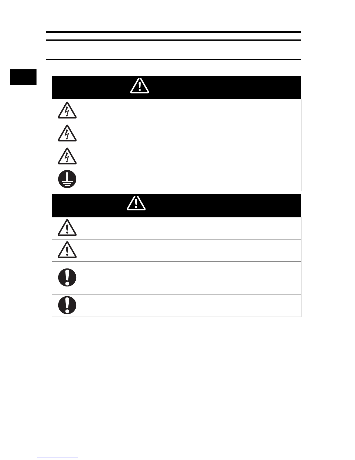
Safety Precautions
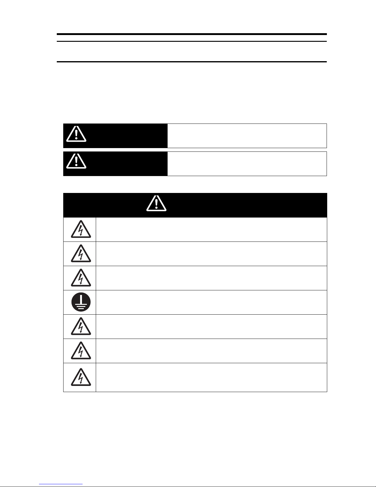
Indications and Meanings of Safety Information
In this user's manual, the following precautions and signal words are used to provide information to ensure the
safe use of the RX Inverter.
The information provided here is vital to safety. Strictly observe the precautions provided.
Meanings of Signal Words
Indicates an imminently hazardous situation which, if not avoided,
is likely to result in serious injury or may result in death. Additionally
there may be severe property damage.
Indicates a potentially hazardous situation which, if not avoided,
may result in minor or moderate injury or in property damage.
Alert Symbols in this Document
Turn off the power supply and implement wiring correctly. Not doing so may result in a serious injury
due to an electric shock.
Wiring work must be carried out only by qualified personnel. Not doing so may result in a serious
injury due to an electric shock.
Do not change wiring and slide switches (SW1), put on or take off Digital Operator and optional
devices, replace cooling fans while the input power is being supplied. Doing so may result in a
serious injury due to an electric shock.
Be sure to ground the unit. Not doing so may result in a serious injury due to an electric shock or
fire.
(200-V class: type-D grounding, 400-V class: type-C grounding)
Do not remove the terminal block cover during the power supply and 10 minutes after the power
shutoff.
Doing so may result in a serious injury due to an electric shock.
Do not operate the Digital Operator or switches with wet hands. Doing so may result in a serious
injury due to an electric shock.
Inspection of the Inverter must be conducted after the power supply has been turned off. Not doing
so may result in a serious injury due to an electric shock.
The main power supply is not necessarily shut off even if the emergency shutoff function is
activated.
5
Page 8

Safety Precautions
CAUTION
Do not connect resistors to the terminals (PD/+1, P/+, N/-) directly. Doing so might result in a smallscale fire, heat generation or damage to the unit.
Install a stop motion device to ensure safety. Not doing so might result in a minor injury. (A holding
brake is not a stop motion device designed to ensure safety.)
Be sure to use a specified type of braking resistor/regenerative braking unit. In case of a braking
resistor, install a thermal relay that monitors the temperature of the resistor. Not doing so might
result in a moderate burn due to the heat generated in the braking resistor/regenerative braking
unit. Configure a sequence that enables the Inverter power to turn off when unusual overheating is
detected in the braking resistor/regenerative braking unit.
The Inverter has high voltage parts inside which, if short-circuited, might cause damage to itself or
other property. Place covers on the openings or take other precautions to make sure that no metal
objects such as cutting bits or lead wire scraps go inside when installing and wiring.
Do not touch the Inverter fins, braking resistors and the motor, which become too hot during the
power supply and for some time after the power shutoff. Doing so may result in a burn.
Take safety precautions such as setting up a molded-case circuit breaker (MCCB) that matches
the Inverter capacity on the power supply side. Not doing so might result in damage to property due
to the short circuit of the load.
Do not dismantle, repair or modify this product.
Doing so may result in an injury.
6
Page 9

Precautions for Safe Use
Precautions for Safe Use
Installation and Storage
Do not store or use the product in the following places.
•Locations subject to direct sunlight.
•Locations subject to ambient temperature exceeding the specifications.
•Locations subject to relative humidity exceeding the specifications.
•Locations subject to condensation due to severe temperature fluctuations.
•Locations subject to corrosive or flammable gases.
•Locations subject to exposure to combustibles.
•Locations subject to dust (especially iron dust) or salts.
•Locations subject to exposure to water, oil, or chemicals.
•Locations subject to shock or vibration.
Transporting, Installation, and Wiring
•Do not drop or apply strong impact on the product. Doing so may result in damaged parts or malfunction.
•Do not hold by the front cover and terminal block cover, but hold by the fins during transportation.
•Do not connect an AC power supply voltage to the control input/output terminals. Doing so may result in
damage to the product.
•Be sure to tighten the screws on the terminal block securely.
Wiring work must be done after installing the unit body.
•Do not connect any load other than a three-phase inductive motor to the U, V, and W output terminals.
•Take sufficient shielding measures when using the product in the following locations. Not doing so may
result in damage to the product.
Locations subject to static electricity or other forms of noise.
Locations subject to strong magnetic fields.
Locations close to power lines.
Operation and Adjustment
•Be sure to confirm the permissible range of motors and machines before operation because the Inverter
speed can be changed easily from low to high.
•Provide a separate holding brake if necessary.
Maintenance and Inspection
•Be sure to confirm safety before conducting maintenance, inspection or parts replacement.
7
Page 10

Precautions for Correct Use
Precautions for Correct Use
Installation
•Mount the product vertically on a wall with the product's longer sides upright.
The material of the wall has to be noninflammable such as a metal plate.
Main Circuit Power Supply
•Confirm that the rated input voltage of the Inverter is the same as AC power supply voltage.
Error Retry Function
•Do not come close to the machine when using the error retry function because the machine may abruptly
start when stopped by an alarm.
•Be sure to confirm the RUN signal is turned off before resetting the alarm because the machine may
abruptly start.
Non-Stop Function at Momentary Power Interruption
•Do not come close to the machine when selecting restart in the non-stop function at momentary power
interruption selection (b050) because the machine may abruptly start after the power is turned on.
Operation Stop Command
•Provide a separate emergency stop switch because the STOP key on the Digital Operator is valid only when
function settings are performed.
•When checking a signal during the power supply and the voltage is erroneously applied to the control input
terminals, the motor may start abruptly. Be sure to confirm safety before checking a signal.
Product Disposal
•Comply with the local ordinance and regulations when disposing of the product.
8
Page 11
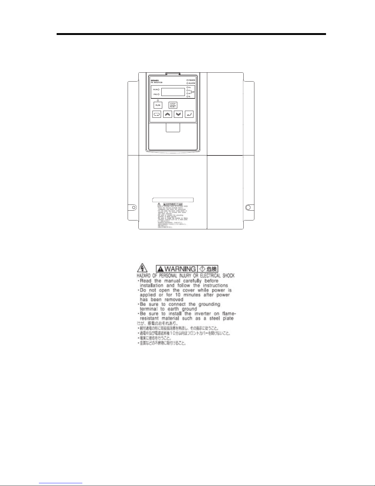
Warning Labels
Warning labels are located on the Inverter as shown in the following illustration.
Be sure to follow the instructions.
Precautions for Correct Use
Warning Description
9
Page 12
Checking Before Unpacking
RX- A2055-EF
Max. applicable motor capacity
004
007
015
022
037
055
075
110
150
185
0.4 kW
0.75 kW
1.5 kW
2.2 kW
3.7 kW
5.5 kW
7.5 kW
11 kW
15 kW
18.5 kW
Voltage class
243-phase 200 V AC (200-V class)
3-phase 400 V AC (400-V class)
Enclosure rating
A
Panel-mounting (IP20 min.) or closed
wall-mounting models
220
300
370
450
550
750
900
11K
13K
22 kW
30 kW
37 kW
45 kW
55 kW
75 kW
90 kW
110 kW
132 kW
E: Europe standard
F: Built-in filter
B IP00
Checking Before Unpacking
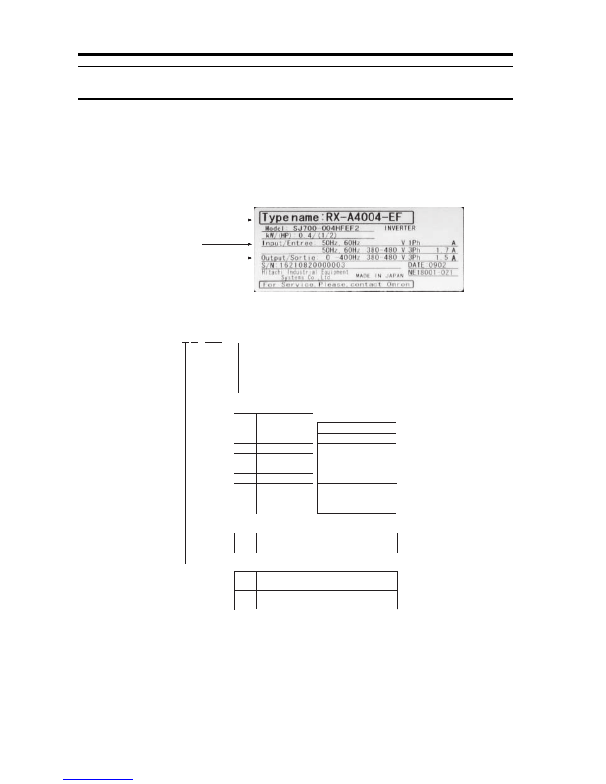
Checking the Product
On delivery, be sure to check that the delivered product is the Inverter RX model that you ordered.
Should you find any problems with the product, immediately contact your nearest local sales
representative or OMRON sales office.
zChecking the Nameplate
Inverter model
Input specifications
Output specifications
zChecking the Model
Checking the Accessories
10
Note that this manual is the only accessory included with the RX model.
Mounting screws and other necessary parts must be provided by the user.
Page 13

Revision History
Revision History
A manual revision code appears as a suffix to the catalog number located at the
lower left of the front and back covers.
Cat. No. I560-E2-03
Revision code
Revision code Revision date Changes and revision pages
01 April 2009 First printing
11
Page 14

Page 15

About This Manual
About This Manual
This User's Manual is compiled chapter by chapter for user's convenience as follows.
Understanding the following configuration ensures more effective use of the product.
Chapter 1 Overview Describes features and names of parts.
Provides external dimensions, installation dimensions, peripheral device
Chapter 2 Design
Chapter 3 Operation
Chapter 4 Functions Describes the functions of the Inverter.
Chapter 5
Chapter 6
Chapter 7 Specifications
Appendix
Maintenance
Operations
Inspection and
Maintenance
design/selection instructions, and other information necessary for
design.
Describes names of parts, the Inverter's operations, including how to use
the keys on the Digital Operator, and the monitor function.
Describes the causes and their countermeasures if the Inverter fails,
including the solutions to possible troubles (troubleshooting).
Describes items for periodical inspection and/or maintenance for the
Inverter.
Provides Inverter specifications, as well as the specifications and
dimensions of peripheral devices.
Describes the summarized parameter settings as a reference for users
who have used this Inverter and understood the functions.
Overview
13
Page 16

Page 17

Contents
Introduction.............................................................................................. 1
Read and Understand this Manual ..........................................................2
Safety Precautions ..................................................................................5
Precautions for Safe Use......................................................................... 7
Precautions for Correct Use ....................................................................8
Checking Before Unpacking .................................................................... 10
Revision History....................................................................................... 11
About This Manual...................................................................................13
Chapter 1 Overview
1-1 Functions .................................................................................................1-1
1-2 Appearance and Names of Parts............................................................. 1-4
Chapter 2 Design
2-1 Installation................................................................................................2-1
2-2 Wiring....................................................................................................... 2-6
Chapter 3 Operation
3-1 Operation Method .................................................................................... 3-3
3-2 Test Run Procedure.................................................................................3-4
3-3 Test Run Operation .................................................................................3-5
3-4 Part Names and Descriptions of the Digital Operator .............................. 3-8
3-5 Keys.........................................................................................................3-11
3-6 Parameter Transition ............................................................................... 3-12
3-7 Parameter List .........................................................................................3-18
Chapter 4 Functions
4-1 Monitor Mode...........................................................................................4-1
4-2 Function Mode ......................................................................................... 4-8
4-3 Functions When PG Option Board (3G3AX-PG01) Is Used....................4-119
4-4 Communication Function ........................................................................4-139
Chapter 5 Maintenance Operations
5-1 Protective Functions and Troubleshooting ..............................................5-1
5-2 Warning Function.....................................................................................5-9
Chapter 6 Inspection and Maintenance
6-1 Inspection and Maintenance.................................................................... 6-1
Chapter 7 Specifications
7-1 Standard Specification List ...................................................................... 7-1
7-2 Dimensional Drawing...............................................................................7-6
7-3 Options ....................................................................................................7-14
15
Page 18

Contents
Chapter App Appendix
Appendix-1Parameter List ................................................................................. App-1
Appendix-2Product Life Curve........................................................................... App-38
Appendix-3Life Alarm Output............................................................................. App-39
Index
16
Page 19

Chapter 1
Overview
1-1 Functions .......................................................... 1-1
1-2 Appearance and Names of Parts .................... 1-4
Page 20

1-1 Functions
1Overview
1
1-1 Functions
RX Inverter Models
Overview
3-phase 200 V AC
3-phase 400 V AC
Rated voltage Enclosure rating Max. applicable motor capacity Model
0.4 kW RX-A2004
0.75 kW RX-A2007
1.5 kW RX-A2015
2.2 kW RX-A2022
3.7 kW RX-A2037
5.5 kW RX-A2055
7.5 kW RX-A2075
11 kW RX-A2110
15 kW RX-A2150
18.5 kW RX-A2185
22 kW RX-A2220
30 kW RX-A2300
37 kW RX-A2370
45 kW RX-A2450
IP20
IP00
55 kW RX-A2550
0.4 kW RX-A4004
0.75 kW RX-A4007
1.5 kW RX-A4015
2.2 kW RX-A4022
4.0 kW RX-A4040
5.5 kW RX-A4055
7.5 kW RX-A4075
11 kW RX-A4110
15 kW RX-A4150
18.5 kW RX-A4185
22 kW RX-A4220
30 kW RX-A4300
37 kW RX-A4370
45 kW RX-A4450
55 kW RX-A4550
75 kW RX-B4750
90 kW RX-B4900
110 kW RX-B411K
132 kW RX-B413K
1-1
Page 21

1-1 Functions
International Standards Models (EC Directives and UL/cUL Standards)
The RX Inverter meets the EC Directives and UL/cUL standard requirements for worldwide use.
Classification Applicable standard
EC Directives EMC Directive EN61800-3: 2004
Low-voltage Directive EN61800-5-1: 2003
UL/cUL Standards UL508C
Human-/Environment-friendly, High-performance, General-purpose
Inverters Suitable for Various Advanced Applications
High Performance
High Starting Torque
With the vector control and auto-tuning functions, the RX Series has achieved high starting torque
in excess of 200% at 0.3 Hz.
1
Overview
Trip Suppression
This Inverter features two trip suppression functions: "Overcurrent trip suppression function" to
suppress overcurrent trip during acceleration, and "Overvoltage suppression function during
deceleration" to suppress overvoltage trip during deceleration. Therefore, the RX Series provides
tough operational capabilities regardless of the severe time setting of acceleration and deceleration.
Various Applications
Sensor-less Vector Control at 0 Hz
The RX Series provides sensor-less vector control, which is useful for up/down applications. It can
provide a high torque of 150%, even at a speed reference of 0 Hz (150% torque is available when
the Inverter capacity is increased by one rank). This function contributes to simplification of control
programs and extension of the service life of the brake.
Emergency Shutoff Function
By switching the dedicated switch (SW1) this function enables you to change the multi-function
input (input 3) to the emergency shutoff input. You can directly turn off a motor control power module
without operating the software. This function simplifies construction of safety applications.
Built-in Braking Circuit (up to 22 kW)
The Inverter models with 22 kW or lower capacity incorporate a braking transistor, enabling spacesaving configuration for applications that need rapid acceleration and stop.
Restart Speed Search Function
For a free-running motor (e.g. a fan motor), this function checks the direction of rotation and
frequency, enabling smooth restart of the motor.
High-torque Multi-operation
The RX Series enables balanced torque control for the whole system, in proportion to multiple motor
loads.
Deceleration Stop During Power Failure
During a power failure or momentary power interruption, the RX Series can decelerate and stop a
motor by using the motor braking energy.
1-2
Page 22

1-1 Functions
Human-/Environment-friendly Features
1
Overview
More Simplified Parameter Settings and View
•Only parameters that have been changed from the default settings can be viewed.
•With the user setting function, only 12 parameters for frequent use can be viewed.
Compliance With Safety Standards
The RX Series meets the requirements of the CE and UL/cUL and complies with various standards.
The RoHS Directive
The standard model meets the requirements of the RoHS Directive.
Easily Meets the Requirements Specified by the Ministry of Land, Infrastructure and
Transport of Japan
The RX Series incorporates a zero-phase reactor (radio noise filter) as a standard specification.
When an optional DC reactor is added, the RX Series meets the requirements specified by the Ministry of Land, Infrastructure and Transport of Japan.
1-3
Page 23
1-2 Appearance and Names of Parts
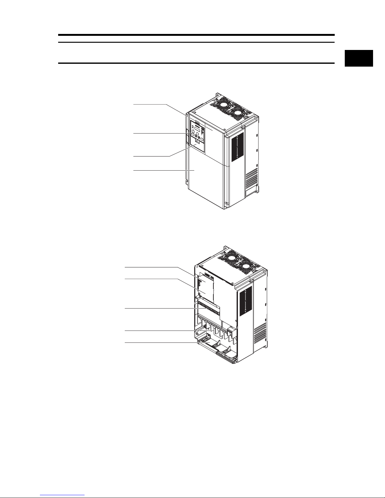
1-2 Appearance and Names of Parts
When the product is unpacked, it appears as below. (Example of RX-A2150/A4150 to A2220/
A4220)
Front cover
Digital Operator
Spacer cover
Terminal block cover
Open the terminal block cover and you can connect cables to the main circuit terminal block, as well
as the control circuit terminal block.
Also, open the front cover and you can mount the optional board.
1
Overview
Position for installing
optional board 1
Position for installing
optional board 2
Control circuit terminal block
Main circuit terminal block
Backing plate
1-4
Page 24

Page 25

Chapter 2
Design
2-1 Installation ........................................................ 2-1
2-2 Wiring ................................................................ 2-6
Page 26
2-1 Installation
WARNING
CAUTION
2Design
2-1 Installation
2
Turn off the power supply and implement wiring correctly. Not doing so may result in a serious injury
due to an electric shock.
Design
Wiring work must be carried out only by qualified personnel. Not doing so may result in a serious
injury due to an electric shock.
Do not change wiring and slide switches (SW1), put on or take off Digital Operator and optional
devices, replace cooling fans while the input power is being supplied. Doing so may result in a
serious injury due to an electric shock.
Be sure to ground the unit. Not doing so may result in a serious injury due to an electric shock or fire.
(200-V class: type-D grounding, 400-V class: type-C grounding)
Do not connect resistors to the terminals (PD/+1, P/+, N/-) directly. Doing so might result in a smallscale fire, heat generation or damage to the unit.
Install a stop motion device to ensure safety. Not doing so might result in a minor injury. (A holding
brake is not a stop motion device designed to ensure safety.)
Be sure to use a specified type of braking resistor/regenerative braking unit. In case of a braking
resistor, install a thermal relay that monitors the temperature of the resistor. Not doing so might result
in a moderate burn due to the heat generated in the braking resistor/regenerative braking unit.
Configure a sequence that enables the Inverter power to turn off when unusual overheating is
detected in the braking resistor/regenerative braking unit.
The Inverter has high voltage parts inside which, if short-circuited, might cause damage to itself or
other property. Place covers on the openings or take other precautions to make sure that no metal
objects such as cutting bits or lead wire scraps go inside when installing and wiring.
2-1
Page 27
2-1 Installation
Safety Information
Installation and Storage
Do not store or use the product in the following places.
•Locations subject to direct sunlight.
•Locations subject to ambient temperature exceeding the specifications.
•Locations subject to relative humidity exceeding the specifications.
•Locations subject to condensation due to severe temperature fluctuations.
•Locations subject to corrosive or flammable gases.
•Locations subject to exposure to combustibles.
•Locations subject to dust (especially iron dust) or salts.
•Locations subject to exposure to water, oil, or chemicals.
•Locations subject to shock or vibration.
Transporting, Installation, and Wiring
•Do not drop or apply strong impact on the product. Doing so may result in damaged parts or malfunction.
•Do not hold by the front cover and terminal block cover, but hold by the fins during transportation.
•Do not connect an AC power supply voltage to the control input/output terminals. Doing so may result in
damage to the product.
•Be sure to tighten the screws on the terminal block securely.
Wiring work must be done after installing the unit body.
•Do not connect any load other than a three-phase inductive motor to the U, V, and W output terminals.
•Take sufficient shielding measures when using the product in the following locations. Not doing so may
result in damage to the product.
Locations subject to static electricity or other forms of noise.
Locations subject to strong magnetic fields.
Locations close to power lines.
2
Design
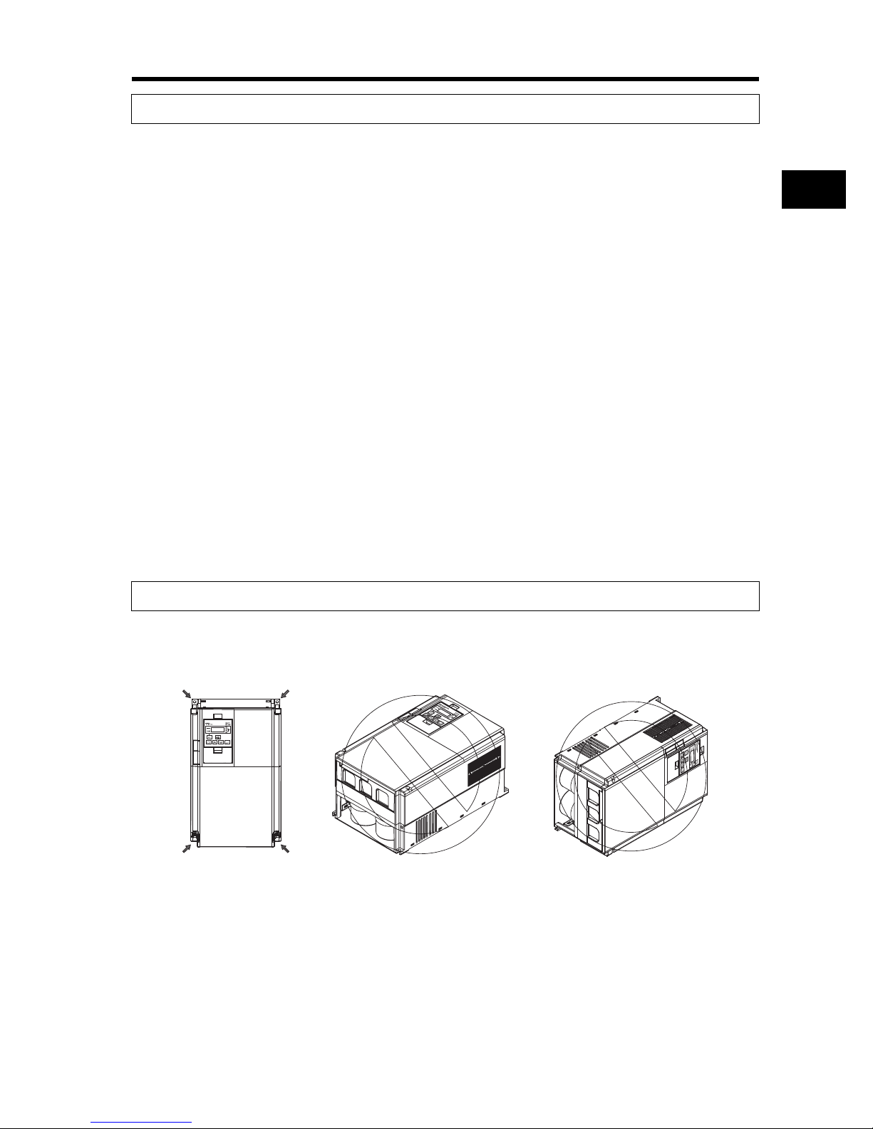
Installation
•Install the Inverter vertically on the wall.
Install the Inverter on a nonflammable wall surface material, like metal.
Position for installing a screw
Main Circuit Power Supply
•Confirm that the rated input voltage of the Inverter matches the AC power supply voltage.
Precautions for Use
2-2
Page 28
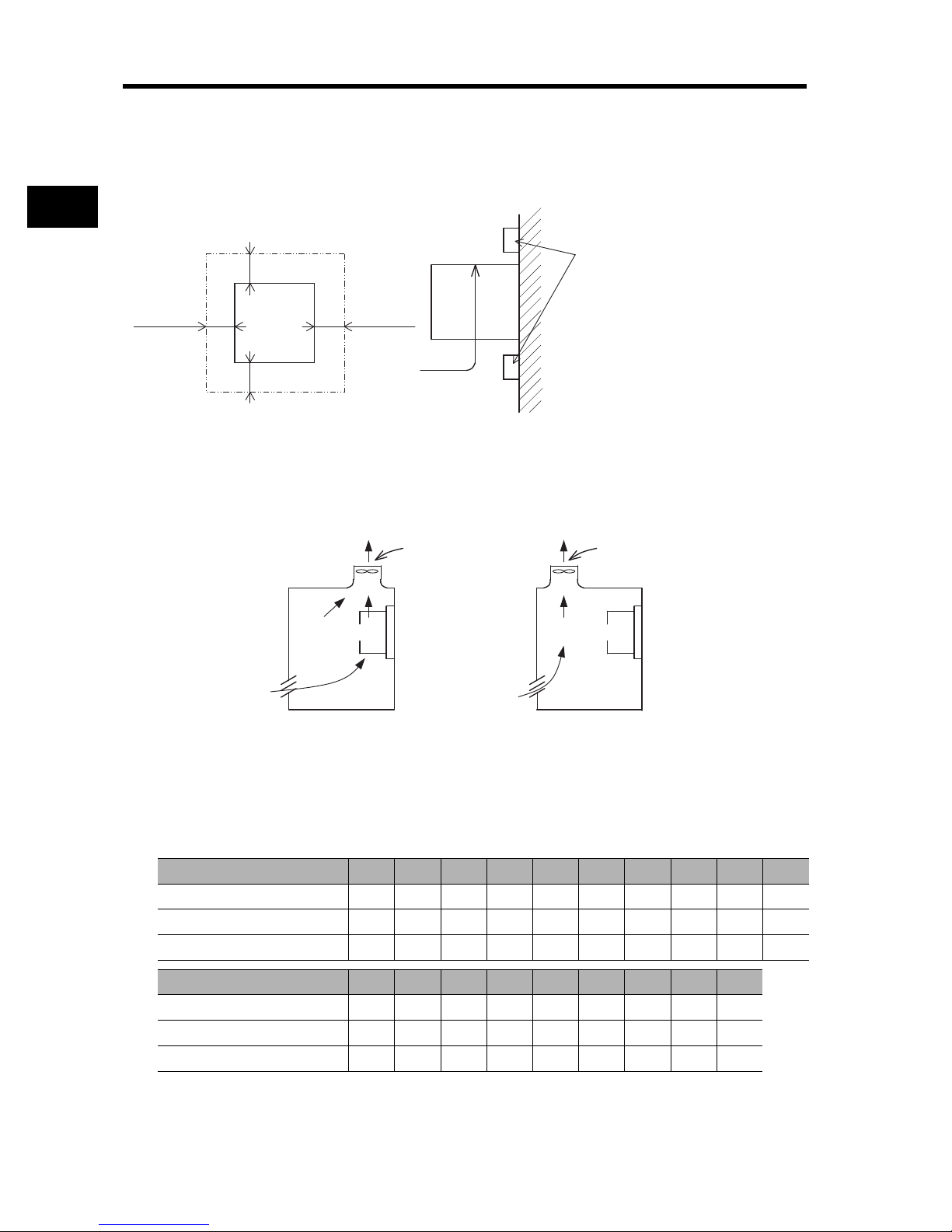
2-1 Installation
Ventilation fan
Ventilation fan
Inverter Inverter
(Correct example) (Incorrect example)
Installation Environment
•Increased ambient temperatures will shorten the life of the Inverter.
•Keep the Inverter away from heating elements (such as a braking resistor, DC reactor, etc.).
If the Inverter is installed in an enclosure, keep the ambient temperature within the range of the
specifications, taking dimensions and ventilation into consideration.
2
Design
*1
Inverter
5 cm min. 5 cm min.
*2
•When several RX models are installed in an enclosure and a ventilation fan is mounted in the
enclosure, be careful about the layout of the Inverters and the air intake apertures.
Depending on the internal layout of the panel, the Inverter's cooling effect may deteriorate,
resulting in an increase in ambient temperature.
Also, use thorough caution in making sure that the Inverter's ambient temperature is within the
allowable operating temperature range.
Airflow
Inverter
Save enough space to prevent the upper
and lower wiring ducts from blocking
cooling airflow.
*1 10 cm min.
*2 10 cm min.
Note that replacing the smoothing capacitor
Wall
requires 22 cm or more.
•Before installing the Inverter, place a cover over all the ventilation openings to shield them from
foreign objects.
After completing the installation process, be sure to remove the covers from the Inverter before
operation.
•Below is the heat radiation according to the Inverter capacity.
Inverter capacity (kw) 0.4 0.75 1.5 2.2 3.7 5.5 7.5 11 15 18.5
Load with 70% loss (W) 64 76 102 127 179 242 312 435 575 698
Load with 100% loss (W)
Efficiency at rated output (%) 85.1 89.5 92.3 93.2 94.0 94.4 94.6 94.8 94.9 95.0
Inverter capacity (kw) 22 30 37 45 55 75 90 110 132
Load with 70% loss (W) 820 1100 1345 1625 1975 2675 3375 3900 4670
Load with 100% loss (W)
Efficiency at rated output (%) 95.0 95.0 95.1 95.1 95.1 95.2 95.2 95.2 95.2
2-3
70 88 125 160 235 325 425 600 800 975
1150 1550 1900 2300 2800 3800 4800 5550 6650
Page 29
2-1 Installation
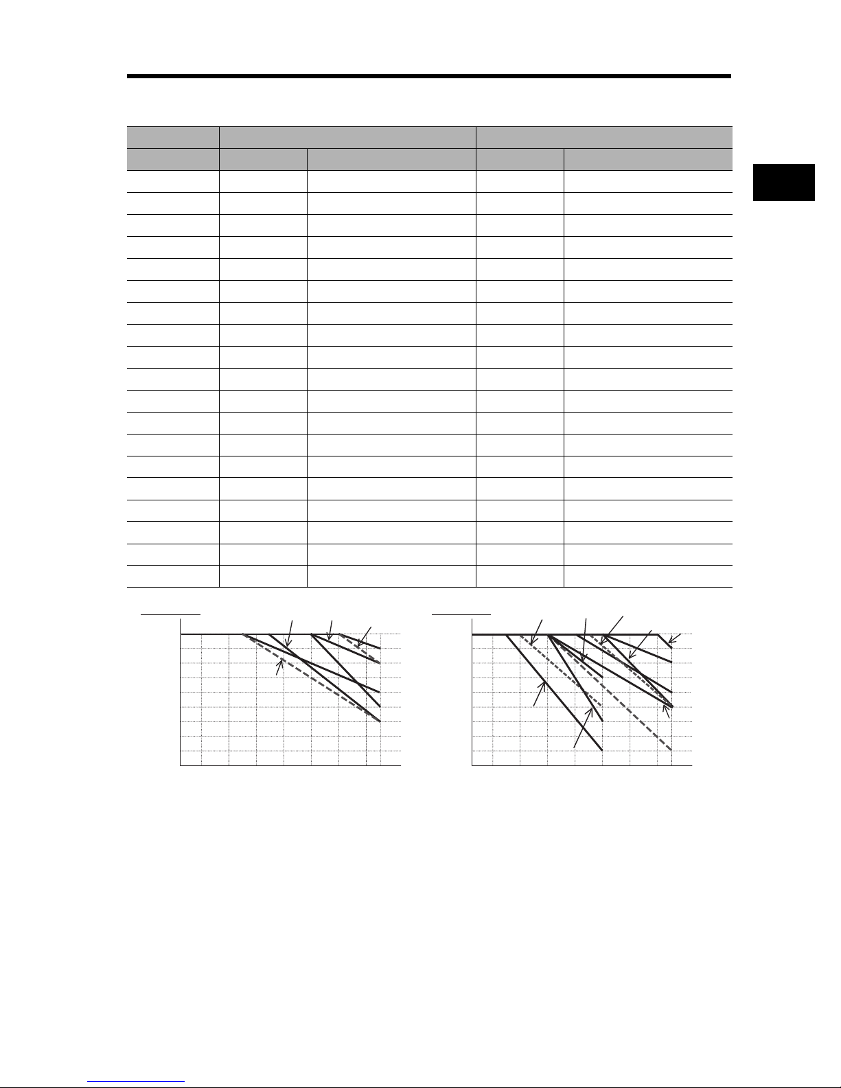
•To raise the carrier frequency, reduce the output current (or derate the rated current) as shown in
the graph below.
Voltage 200-V class 400-V class
Capacity Max. fc (kHz) Derating at fc = 15 kHz Max. fc (kHz) Derating at fc = 15 kHz
0.4 kW 15 100% 15 100%
0.75 kW 15 100% 15 100%
1.5 kW 15 100% 15 100%
2.2 kW 15 100% 15 100%
3.7 kW 15 100% 15 100%
5.5 kW 15 100% 15 100%
7.5 kW 15 100% 15 100%
11 kW 12 90% (41.4 max.) 15 100%
15 kW 12 95% (60.8 A max.) 14 95% (30.4 A max.)
18.5 kW 10 90% (68.4 A max.) 10 90% (34.2 A max.)
22 kW 7 70% (66.5 A max.) 6 75% (36.0 A max.)
30 kW 5 80% (96.8 A max.) 10 75% (43.5 A max.)
37 kW 10 75% (108.7 A max.) 8 80% (60.0 A max.)
45 kW 5 70% (127.4 A max.) 9 75% (68.2 A max.)
55 kW 5 70% (154 A max.) 6 60% (67.2 A max.)
75 kW -- -- 6 85%(126.7 A max.)
90 kW -- -- 4 75% (132.0 A max.)
110 kW -- -- 6 70% (151.9 A max.)
132 kW -- -- 3 60% (156.0 A max.)
2
Design
200-V class 400-V class
100
95
90
85
80
75
70
65
60
Output current derating
55
0.5 2 4 6 8 10 12 1514
45,55 kW
Carrier frequency (kHz)
22 kW
18.5 kW
11 kW
15 kW
30 kW
37 kW
100
95
90
85
80
75
70
65
60
Output current derating
55
0.5 2 4 6 8 10 12 1514
90 kW
132 kW
Carrier frequency (kHz)
75 kW
110 kW
45 kW
30 kW
15 kW
18.5 kW
37 kW
22 kW
55 kW
2-4
Page 30

2
Connecting points
Unnecessary portion
Design
2-1 Installation
Backing Plate
Inverter with 22 kW or Lower Capacity
When running cables, cut the points between the backing plate and unnecessary portions with
nippers or a wire cutter, and remove.
Inverter with 30 kW or Higher Capacity
For Connection Without Cable Conduit
Make a cut in the rubber bushing of the backing plate with nippers or a wire cutter, and insert a cable.
Backing plate
Rubber bushing
For Connection With Cable Conduit
Remove the rubber bushing from the conduit connecting portions, and connect the cable conduit.
* Do not remove the rubber bushing unless you connect a cable conduit.
Otherwise, the cable sheath may be damaged by the inner edge of the backing plate, resulting in
short-circuit or ground fault.
2-5
Page 31

2-2 Wiring
2-2 Wiring
Standard Connection Diagram
DC reactor
(optional)
3-phase 200 V AC
3-phase 400 V AC
To wire the control circuit power
supply and main circuit power
supply separately, be sure to
remove the J51 connector
wire first.
Multi-function input 1
Multi-function input 2
Multi-function input 3
Multi-function input 4
Multi-function input 5
Multi-function input 6
Multi-function input 7
Multi-function input 8
Sequence input common
Thermistor
Frequency setting unit
500 to 2 kΩ
Short-circuit
wire
Frequency reference power supply
Frequency reference input (voltage)
Frequency reference auxiliary input (voltage)
Frequency reference input (current)
Frequency reference common
J51
Control circuit
power supply
PD/+1 P/+
R/L1
S/L2
T/L3
R
T
Ro
To
P24
CM1
FW
1
2
3
4
5
6
7
8
PLC
TH
H
O
O2
OI
L
Braking resistor
(optional)
RBN/-
U/T1
V/T2
W/T3
AL1
Relay output *1
AL2
AL0
Common
11 Multi-function output 1
12 Multi-function output 2
13 Multi-function output 3
14 Multi-function output 4
15 Multi-function output 5
CM2
Multi-function output common
SP
SN
RP
For termination
resistors
SN
Analog monitor output
AM
(voltage output)
Analog monitor output
AMI
(current output)
Digital monitor output
FM
(PWM output)
Option 1
Option 1
2
Design
M
RS485 communication
2-6
Page 32

2
Design
2-2 Wiring
Main Circuit Terminals
Terminal symbol Terminal name Description
R/L1, S/L2,
T/L3
U/T1,V/T2,
W/T3
PD/+1, P/+ External DC reactor
P/+, RB Braking resistor
P/+, N/- Regenerative braking
G Ground terminal Inverter case ground terminal. Connect this terminal to the
Main power supply input
terminal
Inverter output terminal Connect to the 3-phase motor.
terminal
connection terminals
unit connection terminal
Control Circuit Terminal
Connect the input power supply.
Remove the short-circuit bar between terminals "PD/+1"
and "P/+", and connect the optional power factor
improvement DC reactor.
Connect optional external braking resistors. (The RB
terminal is provided for the Inverters with 22 kW or lower
capacity.)
Connect optional regenerative braking units.
ground.
type-D (200-V class), type-C (400-V class)
Analog
Terminal
symbol
H Frequency reference
O Frequency reference
O2 Auxiliary frequency
OI Frequency reference
Frequency reference input
L Frequency reference
Terminal name Description Specifications
power supply output
input
(Voltage)
reference input
(Voltage)
input
(Current)
common
+10 V DC power supply for the O terminal. Allowable load current:
20 mA max.
With a 0 to 10 V DC voltage input, the
frequency reaches the maximum at 10 V.
Set at A014 if the maximum frequency
needs to be achieved at lower than 10 V.
With a 0 to ±10 V DC voltage input, the O2
signal is added to the frequency reference
signal of the O or OI terminal. By changing
the setting, the frequency reference can be
input even with the O2 terminal
independently.
With a 4 to 20 mA DC current input, the
maximum frequency is set at 20 mA. The OI
signal is only active when the AT terminal is
ON. Allocate the AT function to the multifunction input terminal.
Common terminal for the frequency setting
signals (O, O2 and OI) and the analog output
terminals (AM and AMI). Do not connect this
terminal to the ground.
Input impedance 10 k
Allowable input voltage
range:
-0.3 to +12 V DC
Input impedance 10 k
Allowable input voltage
range:
0 to ±12 V DC
Input impedance 100
Allowable max. current:
24 mA
Continued to the next page
2-7
Page 33

2-2 Wiring
Terminal
Analog
Monitor output
Monitor output
Digital (contact)
Power supply
symbol
AM Multi-function analog
AMI Multi-function analog
FM Multi-function digital
P24 Internal 24 V DC 24 V DC power supply for contact input
PLC Input common Common terminal for the interface power
Terminal name Description Specifications
This terminal outputs a signal selected from
output
(Voltage)
output
(Current)
output
the "0 to 10 V DC Voltage Output" monitor
items: Output frequency, Output current,
Output torque (with/without sign), Output
voltage, Input power, Electronic thermal load
rate, LAD frequency, Motor temperature,
and Fin temperature.
This terminal outputs a signal selected from
the "4 to 20 mA DC Current Output" monitor
items: Output frequency, Output current,
Output torque (without sign), Output voltage,
Input power, Electronic thermal load rate,
LAD frequency, Motor temperature, and Fin
temperature.
This terminal outputs a signal selected from
the "0 to 10 V DC Voltage Output (PWM)"
monitor items: Output frequency, Output
current, Output torque (without sign), Output
voltage, Input power, Electronic thermal load
rate, LAD frequency, Motor temperature, Fin
temperature, Digital output frequency, and
Digital current monitor.
"Digital output frequency", and "Digital
current monitor" output a digital pulse at 0/10
V DC pulse voltage and 50% duty ratio.
signal.
When the source logic is selected, this
terminal functions as the contact input
common terminal.
supply P24 terminal, thermistor input TH
terminal and digital monitor FM terminal.
When the sink logic is selected, this terminal
functions as the contact input common
terminal. Do not connect this terminal to the
ground.
Allowable max. current:
2 mA
Allowable load
impedance:
250 max.
Allowable max. current:
1.2 mA
Max. frequency:
3.6 kHz
Allowable max. output
current:
100 mA
2
Design
Continued to the next page
2-8
Page 34

2-2 Wiring
2
Design
Terminal
RUN command
Contact input
Function / Selection
Digital (contact)
Status / Factor
Open collector output
Relay output
Digital (contact)
Status, alarm, etc.
symbol
FW Forward rotation
1
2
3
4
5
6
7
8
CM1 Multi-function input
11
12
13
14
15
CM2 Multi-function output
AL2
AL1
AL0 Relay output
Terminal name Description Specifications
command terminal
Multi-function input Select 8 functions from among the 61 functions
common
Multi-function output Select 5 functions from among 45, and allocate
common
Relay output Select the desired functions from among 45
common
When the FW signal is ON, the motor runs
forward. When it is OFF, the motor decelerates
and stops.
and allocate them to terminals 1 to 8.
Note: Only terminals 1 and 3 can be used for the
emergency shutoff function. For details,
refer to "Emergency Shutoff Function"
(page 2-10).
The sink and source logic for contact input can
be switched by connecting a short-circuit bar on
the control terminal block.
Short-circuiting P24 and PLC Sink logic,
Short-circuiting PLC and CM1 Source logic
To activate contact input via an external power
supply, remove the short-circuit bar and
connect CM1 terminal to the external interface
circuit.
them to terminals 11 through 15.
If an alarm code is selected in C062, terminals
11 to 13, or terminals 11 to 14 always output an
alarm factor code (e.g. Inverter trip). The signal
between each terminal and CM2 always
corresponds to the sink or source logic.
Common terminals for multi-function output
terminals 11 to 15.
functions, and allocate them. SPDT contact
output.
By factory default, the relay output (AL2, AL1)
contact selection (C036) is set at NC contact
between AL2-AL0, and NO contact between
AL1-AL0.
Continued to the next page
[Contact input ON
condition]
Voltage between
each input terminal
and the CM1 terminal
:18 V DC or more
Input impedance
between each input
terminal and the CM1
terminal: 4.7 k
Allowable max.
voltage:
Voltage between
each input terminal
and the CM1
terminal: 27 V DC
Load current at 27 V
DC power supply
voltage:
Approx. 5.6 mA
Between each
terminal and CM2
Voltage drop 4 V
max. at power-on
Max. allowable
voltage: 27 V DC
Max. allowable
current: 50 mA
Contact max.
capacity
AL2-AL0
250 V AC, 2 A
(Resistance)
0.2 A (Induction)
AL1-AL0
250 V AC, 1 A
(Resistance)
0.2 A (Induction)
Contact min. capacity
100 V AC, 10 mA
5 V DC, 100 mA
2-9
Page 35

2-2 Wiring
TH
PLC
Thermistor
8 V DC
10 kΩ
1 kΩ
Analog
Terminal
symbol
TH External thermistor
Sensor
Analog input
Terminal name Description Specifications
Connect an external thermistor to this terminal,
input Terminal
to trip the Inverter when a temperature error
occurs.
The PLC terminal functions as the common
terminal.
[Recommended thermistor characteristics]
Allowable rated power: 100 mW min.
Impedance at temperature error: 3 k
Temperature error detection level is adjustable
between 0 and 9999 .
Slide Switch (SW1) Settings
The built-in slide switch is used to enable or disable the emergency shutoff function. (Factory
Default: Disabled)
* For the location of the slide switch, refer to (page 2-12).
Emergency Shutoff Function (Factory Default: Disabled)
•This function is intended to turn off the Inverter output (stop switching the main element) via only
the multi-function input terminal of the hardware circuit without going through the CPU software.
* This function stops switching of the main element.The circuit is not electrically turned off. While the
power supply is ON, do not touch the Inverter terminals and power cable (e.g. motor cable). Doing
so may result in electric shock, injury or ground fault.
Allowable input
voltage range
0 to 8 V DC
[Input circuit]
2
Design
•When this function is enabled, the multi-function input terminals 1 and 3 are exclusively used for
this function. No other function can be allocated to these terminals. If another function has been
allocated, it will automatically be disabled, and terminals 1 and 3 are changed to the emergency
shutoff terminals.
Function of multi-function input terminal 1
Reset signal (RS) / NO contact (Fixed)
This signal is used to reset the Inverter, and to reset the emergency shutoff trip [ E37.* ].
Function of multi-function input terminal 3
Emergency shutoff signal (EMR) / NC contact (Fixed)
This signal is used to turn off the Inverter output without using the built-in CPU.
With this signal input, the Inverter activates an emergency shutoff trip [ E37. * ].
* If multi-function input terminal 3 has not been connected or disconnected, or if the signal logic is
not matched, the Inverter activates an emergency shutoff trip [E37. *]. After checking the cable
connection and the signal logic, input the reset signal (RS).
Emergency shutoff trip [ E37. * ] can be reset only by the reset signal (RS) via multi-function input
terminal 1. (It cannot be reset with the Digital Operator.)
•To enable this function, set the slide switch SW1 lever in the Inverter to [ON].
(With the factory default setting, slide switch SW1 is [OFF]. [This function is disabled.])
2-10
Page 36

2
Design
2-2 Wiring
Slide switch
(SW1)
setting
SW1 OFF
Emergency
shutoff:
Disabled
(factory
default)
SW1 ON
Emergency
shutoff:
Enabled
*5
Turning SW1
on, and then
off
Emergency
shutoff:
Disabled
*3 *5
* Before operating slide switch SW1, make sure that the input power supply is OFF.
Slide switch SW1 setting and status of multi-function input terminals 1 and 3
Multi-function input terminal 1 Multi-function input terminal 3
Multi-function input 1
selection
[ C001 ]
[Can be selected
randomly]
Factory
*4
01 (RV) Factory
default
Fixed
18 (RS) Fixed
function
(Cannot
be
changed)
[Can be selected
randomly]
Holds
*4
18 (RS) Holds
setting
while SW1
is ON.
Multi-function input 1
operation selection
*1
[ C011 ]
[Can be selected
randomly]
*4
00 (NO) Factory
default
Multi-function input 3
selection
[ C003 ]
[Can be selected
randomly]
*4
12 (EXT) Factory
default
Automatic allocation to multi-function input terminals 1 and 3,
and the input terminal with 18 (RS) setting
function
(Cannot
be
changed)
[Can be selected
randomly]
setting
while SW1
is ON.
00 (NO) Fixed
function
(Cannot
be
changed)
*4
00 (NO)
[Can be selected
Emergency
shutoff
function:
Reset
64 (EMR) Fixed
randomly]
*4
(no
allocation)
no
Multi-function input 3
operation selection
[ C013 ]
[Can be selected
randomly]
default
*3
function
(Cannot
be
changed)
[Can be selected
randomly]
Holds
setting
while SW1
is ON.
*1 *2
*4
00 (NO)
01 (NC)
*4
01 (NC)
*1. With the terminal with input terminal selection [18 (RS)], NO/NC selection is fixed to [00 (NO)].
*2. When [C003] is [64 (EMR)], [C013] is fixed to [01 (NC)].
*3. If [18 (RS)] has been allocated to a multi-function input terminal (except for 3) other than terminal
1 before switch SW1 is set to "ON", the input terminal selection for the relevant terminal will be
automatically changed to "no (no allocation)" by setting SW1 to "ON". This is done in order to
prevent duplicated allocation of this function. Then, even if SW1 is reset to [OFF], the initial
allocation cannot be restored. The User should Re-allocate the terminal function.
Example) When the multi-function input terminal 2 [C002] is [18 (RS)], setting SW1 to [ON] changes
the [C002] setting to [no (no allocation)]. [18 (RS)] will be allocated to the multi-function
input terminal 1 [C001].
Then, even if SW1 is reset to [OFF], the multi-function input terminal 2 [C002] setting is [no (no
allocation)], and the multi-function input terminal 1 [C001] setting is [18 (RS)].
*4. Input terminal selection [64 (EMR)] cannot be selected with the Digital Operator. When slide
switch SW1 is set to [ON], this function will be automatically allocated.
2-11
Page 37

2-2 Wiring
*5. Once slide switch SW1 is set to [ON], allocation of multi-function input terminals 1 and 3 will not
be restored, even if SW1 is reset to [OFF] afterward. Re-allocate the terminal function.
Slide switch SW1
ON
Slide lever (factory default: OFF)
ONOFF
2
Design
Wiring the Main Circuit Terminals
Main Power Supply Input Terminals (R/L1, S/L2, T/L3)
• Use an earth leakage breaker for circuit (wiring) protection between the power supply and the
main power supply terminals (R/L1, S/L2, T/L3).
• An earth leakage breaker may malfunction due to the effect of high frequency. Use an earth
leakage breaker with a large high-frequency sensitivity current rating.
• If the Inverter protection function is activated, a malfunction or accident may have occurred to your
system. Connect a magnetic contactor to turn off the Inverter power supply.
• Do not start or stop the Inverter by switching ON/OFF the magnetic contactor connected on the
Inverter power supply input (primary) side and output (secondary) side.
To start or stop the Inverter via an external signal, use the operation command (FW or RV) on the
control circuit terminal block.
• This Inverter uses a 3-phase power supply. A single-phase power supply cannot be used.
• Do not use this Inverter with a phase loss power input. Doing so may damage the Inverter.
By factory default, the phase loss input protection is disabled. If a phase of power supply input is
interrupted, the Inverter reverts to the following status:
R/L1-phase or T/L3-phase is interrupted:
S/L2-phase is interrupted: The Inverter reverts to single-phase operation, causing a
Even if the power input is under a phase loss condition, the internal capacitor is charged with
voltage, causing an electric shock or injury.
When changing the cable connections, refer to the instructions on page 2-1.
The Inverter does not operate.
trip (due to undervoltage, overcurrent, etc.) or damage to
the Inverter.
2-12
Page 38

2
Design
2-2 Wiring
• In the following cases, the internal converter module may be damaged. Use caution to avoid
them:
Imbalance of power supply voltage is 3% or more.
Power supply capacity is ten times or more than the Inverter capacity, and also 500 kVA or more.
Rapid change in power supply voltage.
Example) When several Inverters are connected with a short bus.
When the phase advance capacitor is turned on/off.
• Do not turn power on/off more than once every 3 minutes.
Doing so may damage the Inverter.
Inverter Output Terminals (U/T1, V/T2, W/T3)
• For connection of the output terminal, use the applicable cable or a cable with a larger diameter.
Otherwise, the output voltage between the Inverter and the motor may drop.
Particularly during low-frequency output, a voltage drop occurs with the cable, resulting in motor
torque reduction.
• Do not mount a phase advance capacitor or surge absorber. These devices cause the Inverter to
trip, or may cause damage to the capacitor or surge absorber.
• If the cable length exceeds 20 m (particularly, with 400-V class), a surge voltage may be
generated at the motor terminal due to stray capacitance or inductance of the cable, causing the
motor to burn out.
• To connect several motors, provide a thermal relay for each.
• The RC value of each thermal relay should be 1.1 times of the motor rated current. The relay may
trip easily depending on the cable length. In this case, connect an AC reactor to the Inverter
output.
DC Reactor Connection Terminal (PD/+1, P/+)
• This terminal is used to connect the optional DC reactor for power factor improvement.
By factory default, a short-circuit bar has been connected between the terminals PD/+1 and P/+.
Before connecting the DC reactor, remove this short-circuit bar.
• The length of the DC reactor connection cable should be 5 m or less.
If the DC reactor is not used, do not remove the short-circuit bar.
If you remove the short-circuit bar without connecting the DC reactor, no power is supplied to
the Inverter main circuit, disabling operation.
External Braking Resistor Connection Terminal (P/+, RB)/Regenerative Braking
Unit Connection Terminal (P/+, N/-)
• The Inverters with 22 kW or lower capacity incorporate a regenerative braking circuit.
To improve braking capability, mount the optional external braking resistor to this terminal.
Do not mount a resistor whose resistance is lower than the specified value. Doing so may damage
the regenerative braking circuit.
• The Inverters with 30 kW or higher capacity do not incorporate a regenerative braking circuit.
To improve braking capability, the optional regenerative braking unit and braking resistor are
required. In this case, connect the regenerative braking unit terminals (+, -) to the Inverter
terminals (P/+, N/-).
• The cable length should be 5 m or less. Twist the two wires.
• Do not connect any device other than the optional regenerative braking unit or external braking
resistor to this terminal.
2-13
Page 39

Ground Terminal (G )
• To prevent electric shock, be sure to ground the Inverter and the motor.
• According to the Electric Apparatus Engineering Regulations, the 200-V class Inverter should be
connected to the grounding electrodes under type-D grounding conditions (conventional type 3
grounding: ground resistance 100 or less), the 400-V class Inverter should be connected to the
grounding electrodes under type-C grounding conditions (conventional special type 3 grounding:
ground resistance 10 or less).
• For the ground cable, use the applicable cable or a cable with a larger diameter. Make the cable
length as short as possible.
• When several Inverters are connected, the ground cable must not be connected across several
Inverters, and must not be looped.
Otherwise, the Inverters may malfunction.
2-2 Wiring
2
Design
Inverter
Inverter
Inverter
Inverter
Inverter
Inverter
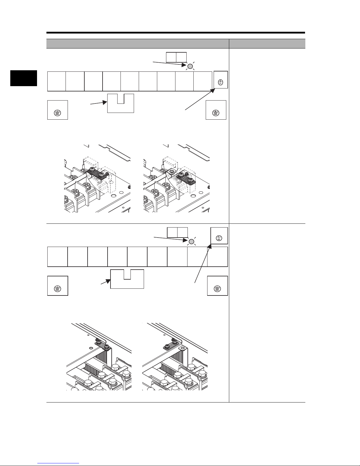
Installing Screws in the Main Circuit Terminal Block
• For the main circuit terminal blocks of RX-A2055/-A2075/-A4055/-A4075, be sure to install the
terminal block screw washers with their grooved sides aligned vertically, as shown below.
Not doing so may result in a contact failure or fire.
(Intended terminals: R/L1, S/L2, T/L3, PD/+1, P/+, N/-, U/T1, V/T2, W/T3, RB)
Your ground bolt
Terminal block screw washer
2-14
Page 40

2
RB
Ro To
G G
CHARGE LED indicator
PD/+1 - P/+ short-circuit bar
When not using the DC reactor,
keep the PD/+1 - P/+ short-circuit bar
attached.
R/L1 S/L2 T/L3
PD/+1
P/+ N/-
U/T1 V/T2 W/T3
Design
2-2 Wiring
Arrangement of Main Circuit Terminals
The terminal arrangement on the Inverter main circuit terminal block is shown below.
Terminal arrangement Applicable model
[EMC filter function switching method]
Dummy plug
(green)
Filter enable pin
(J61)
Short plug
Filter disable pin (J62)
EMC filter disabled
EMC filter enabled (factory default)
Filter enable pin (J61)
Dummy plug (green)
Short plug
In order to enable the EMC filter
function, set up the plug inserted
into the filter enable pin (J61) and
filter disable pin (J62) as shown in
the table below. Confirm that
electrical power has been
disconnected before performing this
setup. Not doing so may result in
electric shock. Also, use with the
plug inserted.
RX-A2004 to A2037
RX-A4004 to A4037
Ro,To: M4
Ground terminal: M4
Others: M4
Filter disable pin (J62)
Short plug
Dummy plug (green)
CHARGE LED indicator
R/L1 S/L2 T/L3 PD/+1
G
Ground terminal with short-circuit
bar (shaded area) for EMC filter
function switching
P/+ N/- U/T1 V/T2 W/T3
PD/+1 - P/+
short-circuit bar
When not using the DC
reactor, keep the PD/+1 - P/+
short-circuit bar attached.
[EMC filter function switching method]
EMC filter enabled (factory default) EMC filter disabled
RB
G
Ro To
RX-A2055, A2075
RX-A4055, A4075
Ro,To: M4
Ground terminal: M5
Others: M5
RX-A2110
RX-A4110
Ro,To: M4
Ground terminal: M6
Others: M5
2-15
Page 41

2-2 Wiring
Ro To
RB
R/L1 S/L2 T/L3 PD/+1
P/+ N/- U/T1 V/T2 W/T3
G
G
Ground terminal with short-circuit
bar (shaded area) for EMC filter
function switching
PD/+1 - P/+ short-circuit bar
When not using the DC
reactor, keep the PD/+1 - P/+
short-circuit bar attached.
CHARGE LED indicator
Terminal arrangement Applicable model
RX-A2150 to A2185
RX-A4150 to A4220
2
[EMC filter function switching method]
EMC filter enabled (factory default) EMC filter disabled
CHARGE LED indicator
R/L1 S/L2 T/L3 PD/+1
Ro To
P/+ N/- U/T1 V/T2 W/T3
Ro,To: M4
Ground terminal: M6
Others: M6
RX-A2220
Ro,To: M4
Ground terminal: M6
Others: M8
RX-A2300
Ro, To: M4
GG
Ground terminal: M6
Others: M8
Design
Ground terminal with short-circuit
bar (shaded area) for EMC filter
function switching
[EMC filter function switching method]
EMC filter enabled (factory default) EMC filter disabled
PD/+1 - P/+ short-circuit bar
When not using the DC reactor,
keep the PD/+1 - P/+
short-circuit bar attached.
RX-A4300
Ro,To: M4
Ground terminal: M6
Others: M6
RX-A2370
RX-A4370
Ro,To: M4
Ground terminal: M8
Others: M8
2-16
Page 42
2
Ro To
GG
G
R/L1 S/L2 T/L3 PD/+1
P/+ N/- U/T1 V/T2 W/T3
Ground terminal with
short-circuit bar (shaded area)
for EMC filter function switching
PD/+1-P/+
short-circuit bar
When not using the DC
reactor, keep the PD/+1-P/+
short-circuit bar attached.
CHARGE LED indicator
Ro To
G
G
G
R/L1 S/L2 T/L3 PD/+1
P/+ N/- U/T1 V/T2 W/T3
Ground terminal with
short-circuit bar
(shaded area) for EMC
filter function switching
PD/+1 - P/+
short-circuit bar
When not using the DC
reactor, keep the PD/+1 - P/+
short-circuit bar attached.
CHARGE LED indicator
Design
2-2 Wiring
Terminal arrangement Applicable model
RX-A2450
RX-A4450
RX-A4550
[EMC filter function switching method]
EMC filter enabled (factory default) EMC filter disabled
Ro,To: M4
Ground terminal: M8
Others: M8
RX-A2550
[EMC filter function switching method]
EMC filter enabled (factory default) EMC filter disabled
2-17
Ro,To: M4
Ground terminal: M8
Others: M10
Page 43

Recommended Cable Size, Wiring Device and Crimp Terminal
For Inverter wiring, crimp terminal and terminal screw tightening torque, refer to the table below.
2-2 Wiring
Power cable
2
Motor
output
200-V class
Applicable
Inverter
(kW)
0.4 RX-A2004 1.25 1.25 1.25 M4 1.25-4
0.75 RX-A2007 1.25 1.25 1.25 M4 1.25-4
1.5 RX-A2015 2 2 2 M4 2-4
2.2 RX-A2022 2 2 2 M4 2-4
3.7 RX-A2037 3.5 3.5 3.5 M4 3.5-4
5.5 RX-A2055 5.5 5.5 5.5 M5 R5.5-5
7.5 RX-A2075 8 8 8 M5 R8-5
11 RX-A2110 14 14 14 M6 R14-6
15 RX-A2150 22 22 22 M6 22-6
18.5 RX-A2185 30 22 30 M6 38-6
22 RX-A2220 38 30 38 M8 38-8
30 RX-A2300
37 RX-A2370
45 RX-A2450
55 RX-A2550
model
(mm
)
R, S, T, U, V,
W, PD/+1,
P/+, N/-
60
(22 × 2)
100
(38 × 2)
100
(38 × 2)
150
(60 × 2)
Ground
cable
(mm
30 M8 60-8
38 M8
38 M8
60 M10 150-10
External
braking resistor
between PD/+1
2
)
and RB (mm
2
)
Terminal
screw
size
*1
*1
Crimp
terminal
100-8
100-8
Tightening
torque
N•m
1.2
(max.1.8)
1.2
(max.1.8)
1.2
(max.1.8)
1.2
(max.1.8)
1.2
(max.1.8)
2.4
(4.0 max.)
2.4
(4.0 max.)
4.0
(4.4 max.)
4.5
(4.9 max.)
4.5
(4.9 max.)
8.1
(8.8 max.)
8.1
(8.8 max.)
8.1
(20.0 max.)
8.1
(20.0 max.)
20.0
(22.0 max.)
Applicable
device
Earth leakage
breaker (ELB)
5 A
10 A
15 A
20 A
30 A
50 A
60 A
75 A
100 A
100 A
150 A
200 A
225 A
225 A
350 A
2
Design
2-18
Page 44

2-2 Wiring
2
Design
Motor
output
(kW)
Applicable
Inverter
model
Power cable
2
(mm
)
R, S, T, U, V,
W, PD/+1,
P/+, N/-
Ground
cable
(mm
External
braking resistor
between PD/+1
2
)
and RB (mm
2
)
Terminal
screw
size
0.4 RX-A4004 1.25 1.25 1.25 M4 1.25-4
0.75 RX-A4007 1.25 1.25 1.25 M4 1.25-4
1.5 RX-A4015 2 2 2 M4 2-4
2.2 RX-A4022 2 2 2 M4 2-4
3.7 RX-A4037 2 2 2 M4 2-4
5.5 RX-A4055 3.5 3.5 3.5 M5 R2-5
7.5 RX-A4075 3.5 3.5 3.5 M5 3.5-5
11 RX-A4110 5.5 5.5 5.5 M6 R5.5-6
15 RX-A4150 8 8 8 M6 8-6
18.5 RX-A4185 14 14 14 M6 14-6
400-V class
22 RX-A4220 14 14 14 M6 14-6
30 RX-A4300 22 22 - M6 22-6
37 RX-A4370 38 22 M8
45 RX-A4450 38 22 M8
55 RX-A4550 60 30 M8
75 RX-B4750
90 RX-B4900
110
132
RX-
B411K
RX-
B413K
100
(38 x 2)
100
(38 x 2)
150
(38 x 2)
80 x 2
38 M10
38 M10
60 M10
80
M10
*1
*1
*1
*1
*1
*1
*1
Crimp
terminal
38-8
38-8
R60-8
100-10
100-10
150-10
80-10
Tightening
torque
N•m
1.2
(max.1.8)
1.2
(max.1.8)
1.2
(max.1.8)
1.2
(max.1.8)
1.2
(max.1.8)
2.4
(4.0 max.)
2.4
(4.0 max.)
4.5
(4.4 max.)
4.5
(4.9 max.)
4.5
(4.9 max.)
4.5
(4.9 max.)
4.5
(4.9 max.)
8.1
(20.0 max.)
8.1
(20.0 max.)
8.1
(20.0 max.)
20.0
(22.0 max.)
20.0
(22.0 max.)
20.0
(35.0 max.)
20.0
(35.0 max.)
Applicable
device
Earth leakage
breaker (ELB)
5 A
5 A
10 A
10 A
15 A
30 A
30 A
50 A
60 A
60 A
75 A
100 A
100 A
150 A
175 A
225 A
225 A
350 A
350 A
*1. When the cable is connected without using the crimp terminal (bare wires), use the square washer included
with the product.
Note: The cable size is based on the HIV cable (75C heat resistance).
2-19
Page 45

2-2 Wiring
Connection for Separating Inverter Control Circuit Power Supply from Main Power Supply
If the Inverter protection circuit is activated to turn off the magnetic contactor of the Inverter input
power supply, the power to the Inverter control circuit is also turned off, and the alarm signal cannot
be kept on.
If the alarm signal must be kept on, use control circuit power supply terminals Ro and To.
Connect control circuit power supply terminals Ro and To to the primary circuit of the magnetic
contactor according to the following procedure.
2
(Connection method)
Incoming electricity specifications
200-V class:
200 to 240 V (+10%, -15%)
50, 60 Hz ±5%
(282 to 339 V DC)
400-V class:
380 to 480 V (+10%, -15%)
50, 60 Hz ±5%
(537 to 678 V DC)
(1) Disconnect the connected wire.
(2) Disconnect the J51 connector.
(3) Connect the control circuit power
cable to the control circuit power
supply terminal block.
* To separate the control circuit power supply (Ro, To) from the main circuit power supply (R/L1, S/
L2, T/L3), observe the following instructions:
• For wiring between terminals Ro and To (terminal screw size: M4), use a cable of 1.25 mm
or more.
• Connect a 3 A fuse to the control circuit power supply cable.
• If the control circuit power supply (Ro, To) is turned on before the main circuit power supply
(R/L1, S/L2, T/L3), ground fault detection at power-on is disabled.
• To use a DC power supply for the control circuit power supply (Ro, To), set the multi-function
output terminal contact selection (C031 to C036) for the multi-function output terminals (11 to
15) and relay output terminals (AL2, AL1, AL0) to "00". If the multi-function output terminal
contact selection is set to "01", the output signal may chatter when the DC power supply is
turned off.
• Tightening torque for terminals Ro and To
M4: 1.2 N•m (1.4 max.)
Design
2
2-20
Page 46

2
Design
2-2 Wiring
Wiring Control Circuit Terminals
• Terminals L and PLC are insulated from each other via the input and output signal common
terminals.
Do not short-circuit or ground these common terminals.
Do not ground these common terminals via external equipment. (Check the external equipment
ground conditions.)
• For wiring the control circuit terminals, use twisted shielded cables (recommended size: 0.75
2
mm
), and connect the shielded cable to each common terminal.
• The control circuit terminal connection cables should be 20 m or less.
• Separate the control circuit terminal connection cables from the main circuit cable (power cable)
and the relay control circuit cable.
• For the connection of the TH (thermistor input) terminal, twist cables with the terminal PLC
individually, and separate them from other PLC common cables.
Since a weak current flows through the thermistor, the thermistor connection cable must be
separated from the main circuit cable (power cable). The thermistor connection cable should be
20 m or less.
TH FW 8 CM1 5
PLC CM1 7
• To use a relay for the multi-function output terminal, connect a surge-absorbing diode in parallel
with the coil.
• Do not short-circuit the analog power supply terminals (between H and L) and/or the interface
power supply terminals (between P24 and PLC).
Doing so may result in failure of the Inverter.
64
Arrangement of the Control Circuit Terminal Block
HO2AMFMTHFW8
L O OI AMI P24 PLC CM1
Terminal screw size M3 Tightening torque 0.7 N·m (0.8 max.)
CM1 5 3 1 14 13 11 AL1
7 6 4 2 15 CM2 12 AL0 AL2
Selecting the Input Control Logic
By factory default the terminal FW and the multi-function input terminal are set to sink logic (NPN).
To change the input control logic to source logic (PNP), remove the short-circuit bar between the
terminals P24 and CM1 on the control circuit terminal block, and connect it between the terminals
CM1 and PLC.
PLC
Thermistor
2-21
Page 47

Selecting the Sequence Input Method (Sink/Source Logic)
P24+V
CM1
PLC
FW
8
24 V DC
Inverter
COM
DC24V
Output unit etc.
2-2 Wiring
When the Inverter's internal interface power supply is
used
P24+V
Sink logicSource logic
Output unit etc.
Output unit etc.
Short-circuit
bar
COM
COM
Short-circuit
0V
bar
CM1
PLC
FW
8
Inverter
P24
CM1
PLC
FW
8
Inverter
24 V DC
24 V DC
When external power supply is used
(Remove the short-circuit bar from the control
terminal block.)
Output unit etc.
COM
24 V DC
0V
P24
CM1
PLC
FW
8
Inverter
24 V DC
2
Design
Selecting the Sequence Output Method (Sink/Source Logic)
11
12
Sink logic
Inverter
24 V DC
CM2
COM
CM2
24 V DC
11
Source logic
12
Inverter
COM
2-22
Page 48

2
Design
2-2 Wiring
Wiring the Digital Operator
• The RX Series Inverter can be operated with the optional 3G3AX-OP01/OP05 as well as the
standard Digital Operator.
• To use the Digital Operator apart from the Inverter body, place an order for the optional cable
3G3AX-CAJOP300-EE (3 m).
• The optional cable should be 3 m or less. Using a cable longer than 3 m may cause malfunction.
Conforming to EC Directives
Conforming Standards
•EMC directive EN 61800-3: 2004
•Low-voltage directive EN 61800-5-1: 2003
Concept of Conformity
EMC Directive
OMRON products are the electrical devices incorporated and used in various machines or
manufacturing equipment. For this reason, we make efforts to conform our products to their related
EMC standards so that the machines or equipment which have incorporated our products should
easily conform to the EMC standards. The RX models have conformed to the EMC directive EN
61800-3 by following the installation and wiring method as shown below. Your machines or
equipment, however, vary in type, and in addition, EMC performance depends on the configuration,
wiring, or location of the devices or control panels which incorporate the EC directive conforming
products. This in turn does not allow us to confirm the condition and the conformity in which our
products are used. Therefore, we appreciate confirmation of the final EMC conformity for the whole
machine or equipment on your own.
Wiring the Power Supply
•Keep the ground cable as short as possible.
•Keep the cable between the Inverter and the noise filter as short as possible.
Connecting a Motor to the Inverter
•When connecting a motor to the Inverter, be sure to use shield braided cables.
•Keep the cables as short as possible.
Low-voltage Directive
The RX models have conformed to the EMC directive EN61800-5-1 by performing the machine installation and wiring as shown below.
•The RX models are an open type device. Be sure to install it inside the control panel.
•The power supply and voltage (SELV) with reinforced or double insulation should be used for
wiring to the control circuit terminals.
•To satisfy requirements of the LVD (low-voltage) directive, the Inverter must be protected with a
molded case circuit breaker (MCCB) in case a short-circuiting accident occurs. Be sure to install a
molded case circuit breaker (MCCB) on the power supply side of the Inverter.
•Use one molded case circuit breaker (MCCB) per Inverter.
•Use the crimp-type terminal with an insulation sleeve to connect to the main circuit terminals.
2-23
Page 49

Chapter 3
Operation
3-1 Operation Method ............................................ 3-3
3-2 Test Run Procedure ......................................... 3-4
3-3 Test Run Operation.......................................... 3-5
3-4 Part Names and Descriptions of the Digital
Operator ............................................................ 3-8
3-5 Keys................................................................... 3-11
3-6 Parameter Transition ....................................... 3-12
3-7 Parameter List .................................................. 3-18
Page 50
3
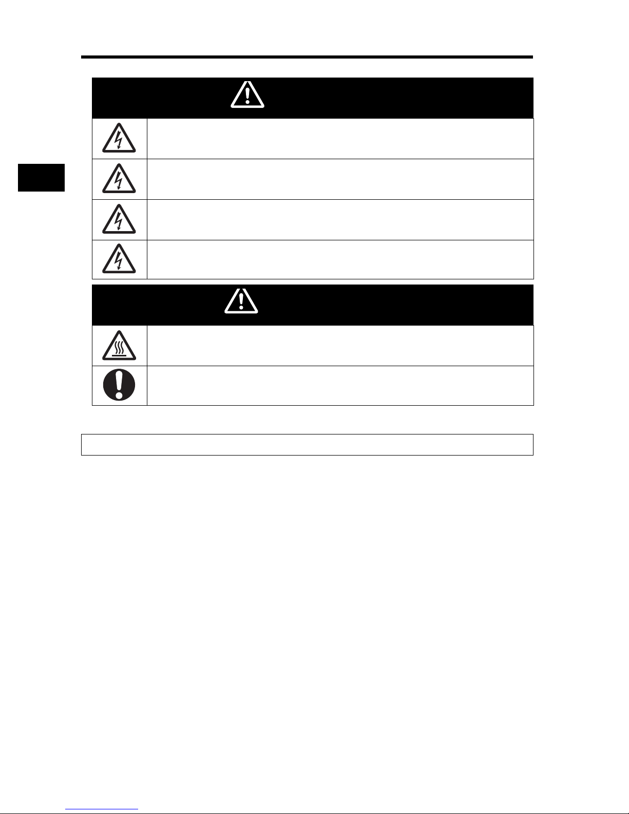
WARNING
CAUTION
Operation
3Operation
Do not change wiring and slide switches (SW1), put on or take off Digital Operator and optional
devices, replace cooling fans while the input power is being supplied. Doing so may result in a
serious injury due to an electric shock.
Do not remove the terminal block cover during the power supply and 10 minutes after the power
shutoff.
Doing so may result in a serious injury due to an electric shock.
Do not operate the Digital Operator or switches with wet hands. Doing so may result in a serious
injury due to an electric shock.
Inspection of the Inverter must be conducted after the power supply has been turned off. Not doing
so may result in a serious injury due to an electric shock.
The main power supply is not necessarily shut off even if the emergency shutoff function is activated.
Do not touch the Inverter fins, braking resistors and the motor, which become too hot during the
power supply and for some time after the power shutoff. Doing so may result in a burn.
Take safety precautions such as setting up a molded-case circuit breaker (MCCB) that matches the
Inverter capacity on the power supply side. Not doing so might result in damage to property due to
the short circuit of the load.
Safety Information
Operation and Adjustment
•Be sure to confirm the permissible range of motors and machines before operation because the Inverter
speed can be changed easily from low to high.
•Provide a separate holding brake if necessary.
3-1
Page 51

Precautions for Use
Error Retry Function
•Do not come close to the machine when using the error retry function because the machine may abruptly
start when stopped by an alarm.
•Be sure to confirm the RUN signal is turned off before resetting the alarm because the machine may
abruptly start.
Non-Stop Function at Momentary Power Interruption
•Do not come close to the machine when selecting restart in the non-stop function at momentary power
interruption selection (b050) because the machine may abruptly start after the power is turned on.
Operation Stop Command
•Provide a separate emergency stop switch because the STOP key on the Digital Operator is valid only when
function settings are performed.
•When checking a signal with the main power supply applied, if a signal voltage is erroneously applied to the
control input terminals, the motor may start abruptly. Be sure to confirm safety before checking a signal.
3
Operation
3-2
Page 52

3-1 Operation Method
3-1 Operation Method
This Inverter has the following operation methods that are selected by the RUN command/
frequency reference settings.
The features and the requirements for each operation method are also given below:
3
Operation
To enter the RUN command/frequency reference via the Digital Operator
This action operates the Inverter via a key sequence of the standard or optional Digital Operator.
When operating the Inverter only via the Digital Operator, the Inverter does not need to be
connected to the control circuit terminal block.
Digital Operator
To enter the RUN command/frequency reference from the control circuit terminal block
This action operates the Inverter by connecting the external signals (from the frequency setting
device, starting switch, etc.) to the control circuit terminal block.
The operation starts by turning ON the RUN command (FW, RV) while the input power supply is
turned ON.
Note: that the frequency can be set using a voltage signal or a current signal from the control circuit
terminal block, which can be selected according to the system. For details, refer to "Control Circuit
Terminal" (page 2-7).
(Requirements for operation)
• RUN command: Switch, Relay etc.
• Frequency reference: External signal (e.g. 0 to 10 V DC, -10 to 10 V DC, 4 to 20 mA)
Frequency reference
(FREQ adjuster)
To enter the RUN command/frequency reference in a combination of Sources
from the Digital Operator and the control circuit terminal block
The RUN command/frequency reference sources can be selected individually from the Digital
Operator as well as the control circuit terminal block.
3-3
Control circuit terminal block
FW
CM1
RUN command (switch)
LOH
Page 53

3-2 Test Run Procedure
3-2 Test Run Procedure
Item Description
Installation and Mounting
Wiring and Connection Connect to the power supply and peripheral devices. 2-6
Power On Check the following before turning on the power.
Display Status Check Make sure that there are no faults in the Inverter.
Install the Inverter according to the installation conditions. 2-1
• Make sure that the installation conditions are met.
• Select peripheral devices that meet the specifications, and wire correctly.
• Make sure that an appropriate power supply voltage is supplied and that the power
input terminals (R/L1, S/L2, and T/L3) are wired correctly.
• RX-A2: 3-phase 200 to 240 V AC
• RX-A4: 3-phase 380 to 480 V AC
• Make sure that the motor output terminals (U/T1, V/T2, and W/T3) are connected to
the motor correctly.
• Make sure that the control circuit terminals and the control device are wired correctly
and that all control terminals are turned off.
• Set the motor to no-load status (i.e., not connected to the mechanical system).
• After checking the above, turn on the power.
• When the power is turned on normally, the display shows:
• RUN LED indicator : ON ALARM LED indicator : OFF
• POWER LED indicator : ON RUN command LED indicator : ON
• Data LED indicator (frequency) : ON
• Data display : Displays the set value in d001.
• If an error occurs, the error code is displayed on the data display. In this case, refer to
"Chapter 5 Maintenance Operations" and make the necessary changes to remedy.
Reference
page
3
Operation
Parameter Initialization Initialize the parameters.
• Set parameter No. b084 to "02", and press the key while holding down the and
keys simultaneously.
Parameter Settings Set the parameters required for a test run.
• Set the motor capacity selection (H003) and the motor pole number selection (H004).
No-load Operation Start the no-load motor via the Digital Operator.
• Display parameter No. F001, set the output frequency using the key and the
key, and press the key. Then, press the key to rotate the motor.
Actual Load Operation Connect the mechanical system and operate via the Digital Operator.
• If there are no difficulties with the no-load operation, connect the mechanical system
to the motor and operate via the Digital Operator.
Operation Refer to "Chapter 4 Functions", and set the necessary parameters.
3-4
Page 54

3
Operation
3-3 Test Run Operation
3-3 Test Run Operation
Power On
Checkpoints Before Turning On the Power
•Make sure that an appropriate power supply voltage is supplied and that the power input terminals
(R/L1, S/L2, and T/L3) are wired correctly.
RX- A2: 3-phase 200 to 240 V AC
RX- A4: 3-phase 380 to 480 V AC
•Make sure that the motor output terminals (U/T1, V/T2, and W/T3) are connected to the motor
correctly.
•Make sure that the control circuit terminals and the control device are wired correctly and that all
control terminals are turned off.
•Set the motor to no-load status (i.e., not connected to the mechanical system).
Power On
•After checking the above, turn on the power.
Display Status Check
•When the power is turned on normally, the display shows:
[Normal] RUN LED indicator (during RUN) : ON ALARM LED indicator : OFF
POWER LED indicator : ON RUN command LED indicator : ON
Data LED indicator (frequency) : ON
Data display : Displays the set value in d001
•If an error occurs, refer to "Chapter 5 Maintenance Operations" and make the necessary changes
to remedy.
[Fault] RUN LED indicator (during RUN) : ON ALARM LED indicator : ON
POWER LED indicator : ON RUN command LED indicator : ON
Data LED indicator (frequency) : ON
Data display : An error code, such as "E-01", is displayed.
(The display varies depending on the type of error.)
3-5
Page 55

Parameter Initialization
bk-k-k-
•Initialize the parameters using the following procedure.
•To initialize the parameters, set parameter b084 to "02".
Key sequence Display example Description
3-3 Test Run Operation
k0.0
bk0k0k1
bk0k8k4
0k0
0k2
bk0k8k4
Power On
Press the Mode key once, and then press the Decrement key three
times to display "b---".
Press the Mode key.
"b001" is displayed.
Use the Increment or Decrement key to display "b084".
Press the Mode key. The set value in "b084" is displayed.
Use the Increment or Decrement key to display "02".
Press the Enter key. The set value is entered and "b084" is displayed.
3
Operation
Press the STOP/RESET key while holding down the Mode and
Decrement keys simultaneously.
When the display blinks, release the STOP/RESET key first, and then
the Mode and Decrement keys.
Displays initialization.
=k.k0k0
(In 1 s) The parameter number is displayed again in approximately 1 s.
dk0k0k1
3-6
Page 56

3
Operation
3-3 Test Run Operation
No-load Operation
•Start the no-load motor (i.e., not connected to the mechanical system) using the Digital Operator.
Forward/Reverse Rotation via the Digital Operator
Key sequence Display example Description
Press and hold the Mode key for 3 seconds or more to display "d001",
0.0
6.0
•Make sure that no errors have occurred in the Inverter during operation.
•Switch between forward and reverse with the operator rotation direction selection (F004).
Stopping the Motor
•After completing the no-load operation, press the STOP/RESET key. The motor will stop.
and then press again.
(Monitors the frequency reference.)
Press the RUN key.
The RUN command LED indicator is lit and the monitor value of the
frequency reference is displayed. (Factory default: F001 = 6)
Actual Load Operation
•After checking the operation with the motor in the no-load status, connect the mechanical system
and operate with an actual load.
Connecting the Mechanical System
•After confirming that the motor has stopped completely, connect the mechanical system.
•Be sure to tighten all the screws when fixing the motor axis and the mechanical system.
Operation via the Digital Operator
•Because a possible error may occur during operation, make sure that the STOP/RESET key on
the Digital Operator is easily accessible.
•Use the Digital Operator to operate the Inverter the same way as in no-load operation.
Checking the Operating Status
•After making sure that the operating direction is correct and that the Inverter is operating smoothly
at a slow speed, increase the frequency reference.
•By changing the frequency reference or the rotation direction, make sure that there is no vibration
or abnormal sound from the motor.
Make sure that the output current (output current monitor [d002]) is not excessive.
3-7
Page 57

3-4 Part Names and Descriptions of the Digital Operator
3-4 Part Names and Descriptions of the
Digital Operator
Part Names and Descriptions
Data display
RUN command LED indicator
Operation keys
3
Operation
8.8.8.8.
Name Function
POWER LED indicator Lit when the power is supplied to the control circuit.
ALARM LED indicator Lit when an Inverter error occurs.
RUN (during RUN)
LED indicator
PROGRAM LED
indicator
Data display Displays relevant data, such as frequency reference, output
Data LED indicator Lit according to the indication on the data display.
RUN command LED
indicator
RUN key Activates the Inverter. Available only when operation via the
STOP/RESET key Decelerates and stops the Inverter. Functions as a reset key if
Mode key Switches between: the monitor mode (d), the basic
Enter key Enters the set value.
Increment key Changes the mode.
Lit when the Inverter is running.
Lit when the set value of each function is indicated on the data
display.
Blinks during warning (when the set value is incorrect).
current, and set values.
Hz: Frequency V: Voltage A: Current kW: Power %: Ratio
Lit when the RUN command is set to the Digital Operator. (The
RUN key on the Digital Operator is available for operation)
Digital Operator is selected.
(Check that the RUN command LED indicator is lit.)
an Inverter error occurs.
function mode (F), and the extended function mode
(A, b, C, H).
(To change the set value, be sure to press the Enter key.)
Also, increases the set value of each function.
3-8
Page 58

3
0.00
dk0k0k1
dk0k0k1
0.00
dk0k0k1
Operation
3-4 Part Names and Descriptions of the Digital Operator
Name Function
Decrement key Changes the mode.
Also, decreases the set value of each function.
Display System and Key Sequence of Each Code
• This section explains the examples of typical operation (Basic display, Complete display) and the
extended function mode U as a special operation.
This operation can be performed when other display modes are selected.
The display indicates the setting of "b038" when the power is turned on. For details, refer to
"Initial Screen Selection (Initial Screen at Power-ON)" (page 4-56).
When "b038 = 01" (factory default), for output frequency monitor "d001" is displayed.
Press the Mode key to display .
Note: The Digital Operator display varies depending on the settings of display selection "b037", ini-
tial screen selection "b038", and user parameter automatic setting function selection "b039".
For details, refer to "Display Selection" (page 4-53), "Initial Screen Selection (Initial Screen
at Power-ON)" (page 4-56), "User Parameter Automatic Setting Function" (page 4-57).
Item Function code Data Description
00 Complete display
01 Individual display of functions
Display selection b037
Initial screen
selection
(Power On)
User parameter
automatic setting
function selection
b038 *
b039
*
02 User setting
03 Data comparison display
04 Basic display (factory default)
00 Screen when the Enter key was pressed last
01 d001 (Output frequency monitor) (factory default)
02 d002 (Output current monitor)
03 d003 (Rotation direction monitor)
04 d007 (Frequency conversion monitor)
05 F001 (Output frequency setting/monitor)
00 Disabled (factory default)
01 Enabled
*Not displayed by factory default.
* To return the display to or
the following procedures.
• Hold down the Mode key for 3 seconds or more to display and
Press the Mode key to display or
* shows the status during stop. Displays the output frequency of the Inverter during
0.00
operation.
3-9
dk0k0k1
*
from any display on the Digital Operator, refer to
0.00
*
0.00
.
*
alternately.
Page 59

3-4 Part Names and Descriptions of the Digital Operator
Operation Example for Basic Display (factory default: "b037 = 04")
• Displays the limited basic parameters.
Monitor mode : All
Basic function mode : 4 parameters
Extended function mode : 24 parameters
• Other parameters than those mentioned above are not displayed. To display all parameters, select
"Complete display 'b037 = 00'".
<Parameters to be Displayed and Arrangement>
3
NO. Display code Item
1 d001 to d104 Monitor display
2 F001 Output frequency setting/monitor
3 F002 Acceleration time 1
4 F003 Deceleration time 1
5 F004 Operator rotation direction selection
6 A001 Frequency reference selection
7 A002 RUN command selection
8 A003 Base frequency
9 A004 Maximum frequency
10 A005 O/OI selection
11 A020 Multi-step speed reference 0
12 A021 Multi-step speed reference 1
13 A022 Multi-step speed reference 2
14 A023 Multi-step speed reference 3
15 A044 V/f characteristics selection
16 A045 Output voltage gain
17 A085 RUN mode selection
18 b001 Retry selection
19 b002 Allowable momentary power interruption time
20 b008 Trip retry selection
21 b011 Trip retry wait time
22 b037 Display selection
23 b083 Carrier frequency
24 b084 Initialization selection
25 b130 Overvoltage protection function during deceleration
26 b131 Overvoltage protection level during deceleration
27 C021 Multi-function output terminal 11 selection
28 C022 Multi-function output terminal 12 selection
29 C036 Relay output (AL2, AL1) contact selection
*
Operation
* If the intended parameter is not displayed, check the setting of display selection "b037".
To display all parameters, set "00" to "b037".
3-10
Page 60
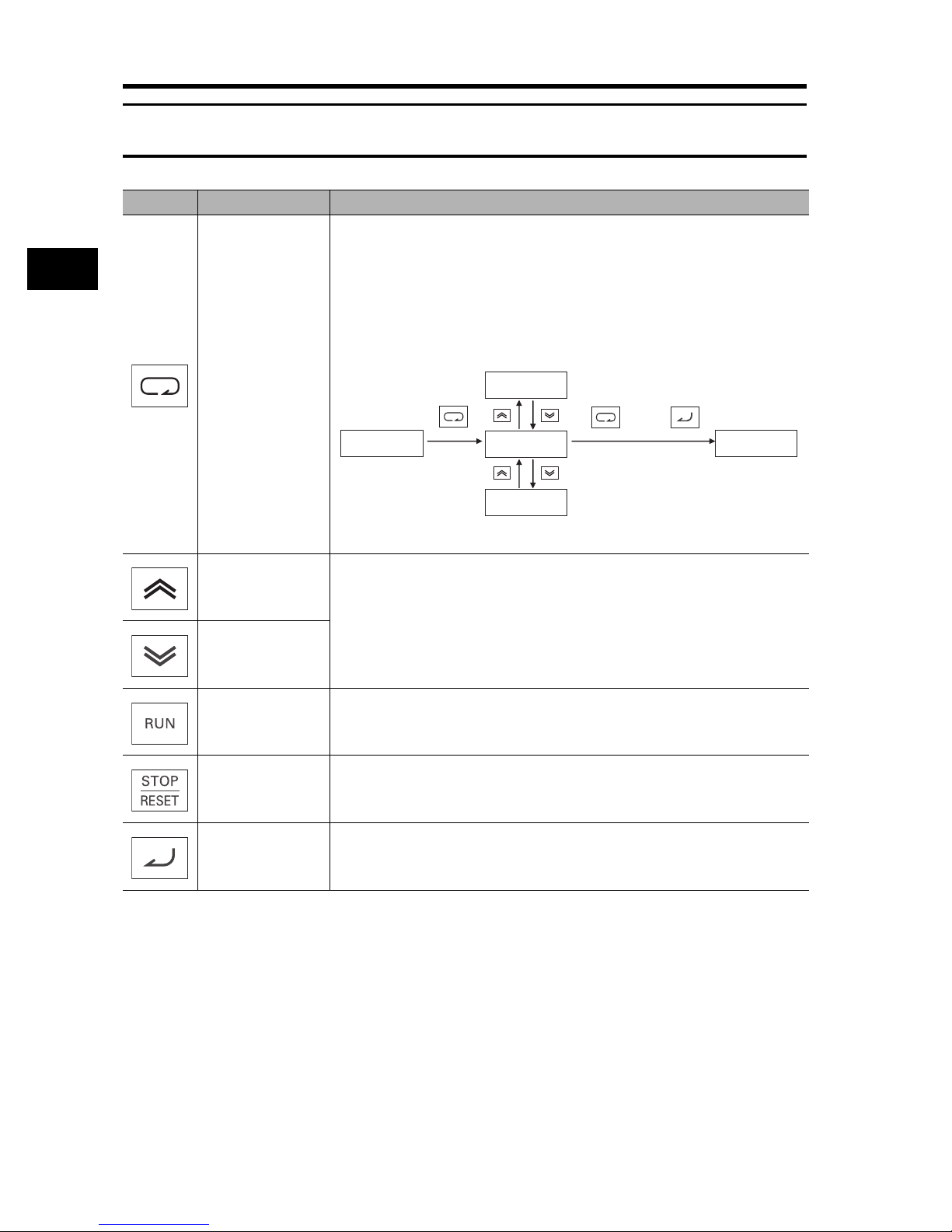
3-5 Keys
3-5 Keys
Name Description
Switches between the command setting and the data setting, and between the
function mode and the extended function mode.
3
With this key, you can always change the display as follows:
[Supplemental Information]
To jump to "d001" from any function mode, hold down the Mode key for 3
seconds.
Operation
Mode key
fk0k0k1 fk0k0k1
k5k8.1
or
5k8.0
5k7.9
Note: Always press the Enter key to store any changed data.
Increment key
Changes the set values, parameters, and commands.
Decrement key
RUN key Starts the operation. Forward/Reverse rotation depends on the "F004" setting.
STOP/RESET key Stops the operation. Functions as a reset key if an error occurs.
Enter key
3-11
Enters and stores changed data.
Do not press the Enter key if you don't want to store any changes, for example, if
you change the data inadvertently.
Page 61
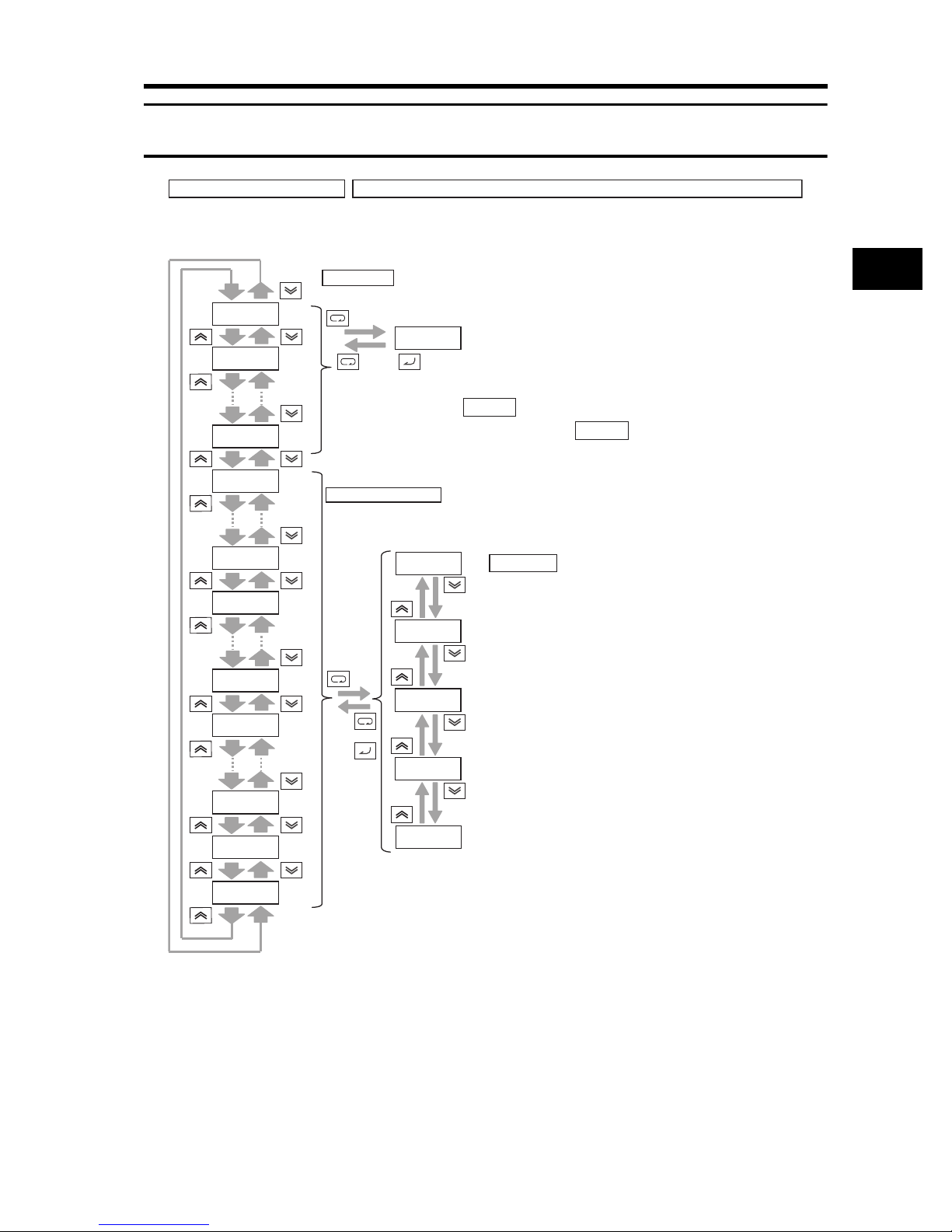
3-6 Parameter Transition
3-6 Parameter Transition
Operation and sequence of code display
Press the Increment/Decrement key to scroll through codes in the code display and to increase/decrease the number in the data
display. Press either key until you see the desired code or data. For fast-forwarding, press and hold either key.
Monitor Mode
Press the Mode key in the code display to display its monitor value.
Operation and sequence of monitor/data display
dk0k0k1
(Monitor display) *1
0.0k0
dk0k0k1
*1 *2
Data setting
Press the Increment/Decrement key to increase/decrease the
number.
(Set the desired number.)
Press the Enter key in the data display to fix the data and to
return to the code display.
Press the Mode key in the data display to return to its code
display without changing the data.
dk0k0k2
dk1k0k4
fk0k0k1
fk0k0k4
ak0k0k1
ak0k8k5
bk0k0k1
0.0k0
or
Press the Mode/Enter key in the monitor display to return to its code display.
Note: By factory default, appears at power-on.
Press the Mode key in this status to display .
Function/Extended Function Mode
Press the Mode key in the code display to display its data.
(Data display)
To upper limit
3k0.0k1
3k0.0k0
or
3
Operation
bk1k3k1
ck0k2k1
ck0k2k2
2k9.9k9
To lower limit
*1. The setting displayed varies depending on the parameter.
*2. To change the data, be sure to press the Enter key.
3-12
Page 62

3-6 Parameter Transition
Operation Example for Complete Display (Default: "b037 = 00")
Displays all parameters.
3
Operation
Operation and sequence
of code display
(Monitor/Function modes)
Press the Increment/Decrement key to scroll through codes in the code display and to increase/decrease the number in the
data display.
Press either key until you see the desired code or data. For fast-forwarding, press and hold either key.
dk0k0k1
dk0k0k2
dk1k0k4
fk0k0k1
fk0k0k4
ak-k-k-
Operation and sequence of
monitor/data display
(Monitor/Function modes)
Monitor
mode
0.0k0
or
Function
mode
3k0.0k1
3k0.0k0
or
2k9.9k9
Operation and sequence of
code display
(Extended function mode)
(Monitor display) *1
*1. The setting displayed varies depending on the parameter.
*2. To change the data, be sure to press the Enter key.
(Data display) *1 *2
ak0k0k1
or
ak1k5k3
Operation and sequence of
monitor/data display
(Extended function mode)
Extended
function
mode A
or
(Data display)
*1 *2
3
2
1
bk0k0k1
Extended
function
bk-k-k-
or
bk1k3k2
mode B
ck-k-k-
hk-k-k-
pk-k-k-
uk-k-k-
Key sequence and display system
of extended function mode U
or
(See the next page.)
ck0k0k1
Extended
function
mode C
or
ck1k5k9
hk0k0k1
Extended
function
or
hk0k7k3
mode H
pk0k0k1
Extended
function
mode P
or
pk1k3k1
3-13
Page 63
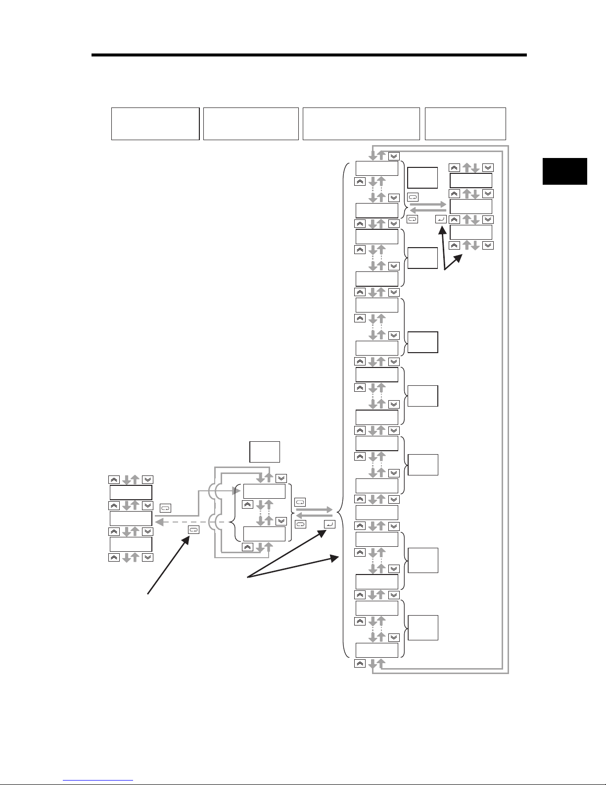
3-6 Parameter Transition
Display System and Key Sequence of Extended Function Mode U
The extended function mode U is the parameter to optionally register (or automatically record) other
extended function codes, and differs in operation from other extended function modes.
Operation and sequence of
code display
(Monitor/Function modes)
*1. The setting displayed varies depending on the parameter.
*2. To change the data, be sure to press the Enter key.
Operation and sequence of
code display
(Extended function mode U)
Operation and sequence of code display
Displaying another mode
from extended function mode U
ak0k0k1
Extended
ak1k5k3
bk0k0k1
Extended
bk1k3k2
ck0k0k1
Extended
ck1k5k9
hk0k0k1
Extended
hk0k7k3
Operation and sequence
of monitor/data display
(Monitor/Function/Extended
function modes)
*1 *2
(Data display)
function
mode A
3
2
or
1
function
mode B
Press the Enter key to
reflect the set value in each
parameter.
Note that no data can be
fixed in parameter "U".
function
mode C
function
mode H
3
Operation
pk-k-k-
uk-k-k-
dk0k0k1
Pressing the Enter key
does not return.
Extended
function
mode U
uk0k0k1
uk0k1k2
Press the Enter key to enter
the selected code
in parameter "U".
pk0k0k1
Extended
function
mode P
pk1k3k1
(Factory default)
or
nko
dk0k0k1
Monitor
mode
dk1k0k4
fk0k0k1
Function
mode
fk0k0k4
3-14
Page 64

3
Press and simultaneously. *1
*2 *3
dk0k0k1
Press (2 times).
("A001" is displayed.)
*3
Operation
3-6 Parameter Transition
Direct Code Specification and Selection
• The codes can be specified or selected by directly entering each digit of the codes or data, as well
as by scrolling the codes of the monitor, basic function, and extended function modes.
• Below is an example where monitor mode code "d001" is changed to extended function code
"A029".
1. Display the monitor mode code.
("d001" is displayed.)
dk0k0k1
2. Change the extended function mode.
ak0k0k1
• "d" of the 4th digit on the left starts to blink.
• "A" blinks.
• Press the Enter key to fix the blinking digit.
*2
(Continued to the next page)
3-15
Press .
("A" is entered.)
Page 65

3. Change the 3rd digit of the extended function code.
ak0k0k1
Press .
*2
("0" is entered.)
*2
• "0" of the 3rd digit blinks.
• Press the Enter key to fix "0" of the 3rd digit as
you need not change it.
4. Change the 2nd digit of the extended function code.
• "0" of the 2nd digit blinks.
3-6 Parameter Transition
3
Operation
ak0k0k1
Press (2 times).
ak0k2k1
Press .
*2
(Continued to the next page)
("A021" is displayed.)
• "2" of the 2nd digit blinks.
3-16
Page 66

3-6 Parameter Transition
ak0k2k1
ak0k2k9
*2
Press .
("9" is entered.)
5. Change the 1st digit of the extended function code.
• "1" of the 1st digit blinks.
3
Press or ("A029" is displayed).
(8 times) (2 times)
Operation
6. The extended function code setting is complete.
ak0k2k9
• "9" of the 1st digit blinks.
• The code display "A029" selection is complete.
Note: "A" of the 4th digit on the left starts to blink
again when entering codes which have not
been selected for display or codes not on the
list.
Refer to
Screen Selection (Initial Screen at Power-ON)"
(page 4-56)
Setting Function" (page 4-57)
Parameter List" to check the code, and enter
again.
"Display Selection" (page 4-53), "Initial
, "User Parameter Automatic
, and "Appendix
7. Press the Mode key to display the data. Use the Increment/Decrement keys to change the data
and press the Enter key to set it.
The data can be set in the same procedure as 1 to 6.
*1 This operation is available even if code "d001" is not displayed.
*2 If pressing the Mode key while each digit is blinking, the display returns the status for the 1-digit
higher entry.
*3 If pressing the Mode key while the 4th digit on the left is blinking, the values under entry are
canceled and the display returns to the status before pressing the Increment and Decrement
keys simultaneously in 1.
*4 To change the data, be sure to press the Mode key.
3-17
4
*
4
*3 *
Page 67

3-7 Parameter List
Monitor Mode (d)
•The default setting displays "d001" at power-on. To select the optional display, change the setting
in "b038".
Parameter
No.
d001
d002
d003
d004
Function name Monitor or data range
Output frequency
monitor
Output current
monitor
Rotation direction
monitor
PID feedback value
monitor
0.0 to 400.0 Yes Hz 4-1
0.0 to 999.9
1000 to 9999
F: Forward
o: Stop
r: Reverse
0.00 to 99.99
100.0 to 999.9
1000. to 9999.
1000 to 9999 (10000 to 99990)
100 to 999 (100000 to 999000)
(Enabled when the PID function is selected)
3-7 Parameter List
Default
setting
Changes
during
operation
A4-1
4-1
4-1
Unit Page
3
Operation
d005
d006
d007
d008
d009
d010
d012
d013
d014 Input power monitor 0.0 to 999.9 kW 4-4
d015
Multi-function input
monitor
Multi-function
output monitor
Output frequency
monitor
(after conversion)
Actual frequency
monitor
Torque reference
monitor
Torque bias
monitor
Output torque
monitor
Output voltage
monitor
Integrated power
monitor
FW
87654321
AL2 15 14 13 12 11
0.00 to 99.99
100.0 to 999.9
1000. to 9999.
1000 to 3996 (10000 to 39960)
(Output frequency × Conversion factor of b086)
-400. to -100.
-99.9 to 0.00 to 99.99
100.0 to 400.0
-200. to +200. %4-3
-200. to +200. %4-3
-200. to +200. %4-3
0. to 600. V4-3
0.0 to 999.9
1000. to 9999.
1000 to 9999 (10000 to 99990)
100 to 999 (100000 to 999000)
(Example) Terminals FW, 7, 2, 1 : ON
Terminals 8, 6, 5, 4, 3: OFF
(Example) Terminals 12, 11 : ON
Terminals AL2, 15, 14, 13: OFF
4-2
4-2
Yes 4-2
Hz 4-3
4-4
3-18
Page 68

3-7 Parameter List
3
Operation
Parameter
No.
d016 Total RUN time
d017
d018
d019
d022
d023 Not used
d024 Not used
d025 Not used
d026 Not used
d027 Not used
d028
d029
d030
d080
d081
d082
d083
d084
d085
d086
d090 Warning monitor Warning code 4-6
d102 DC voltage monitor 0.0 to 999.9 V4-6
d103
d104
Function name Monitor or data range
0. to 9999.
1000 to 9999 (10000 to 99990)
100 to 999 (100000 to 999000)
Power ON time
monitor
Fin temperature
monitor
Motor temperature
monitor
Life assessment
monitor
Pulse counter
monitor
Position command
monitor
Current position
monitor
Fault frequency
monitor
Fault monitor 1 (Latest)
Fault monitor 2
Fault monitor 3
Fault monitor 4
Fault monitor 5
Fault monitor 6
Regenerative
braking load rate
monitor
Electronic thermal
monitor
0. to 9999.
1000 to 9999 (10000 to 99990)
100 to 999 (100000 to 999000)
-020. to 200.0 C4-4
-020. to 200.0 C4-5
ON
1: Capacitor on the main circuit board
OFF
2
0 to 2147483647 (Displays MSB 4 digits) 4-5
-1073741823 to 1073741823
(Displays MSB 4 digits including "-")
-1073741823 to 1073741823
(Displays MSB 4 digits including "-")
0. to 9999.
1000 to 6553 (10000 to 65530)
Error code (condition of occurrence)
Output frequency [Hz] Output current [A]
Internal DC voltage [V]
RUN time [h]
ON time [h]
0.0 to 100.0 %4-6
0.0 to 100.0 %4-7
2: Cooling fan rotation speed reduced
1
Default
setting
Changes
during
operation
h4-4
h4-4
4-5
4-5
Time 4-5
Unit Page
4-5
4-132
4-6
4-6
4-6
4-6
4-6
4-6
3-19
Page 69

Basic Function Mode (F)
3-7 Parameter List
Parameter
No.
F001
F002 Acceleration time 1
F202
F302
F003 Deceleration time 1
F203
F303
F004
Function name Monitor or data range
Output frequency
setting/monitor
* 2nd acceleration
time 1
* 3rd acceleration
time 1
* 2nd deceleration
time 1
* 3rd deceleration
time 1
Operator rotation
direction selection
0.0/Starting frequency to 1st/2nd/3rd max.
frequency
0.0 to 100.0 (PID control enabled)
0.01 to 99.99
100.0 to 999.9
1000. to 3600.
0.01 to 99.99
100.0 to 999.9
1000. to 3600.
0.01 to 99.99
100.0 to 999.9
1000. to 3600.
0.01 to 99.99
100.0 to 999.9
1000. to 3600.
0.01 to 99.99
100.0 to 999.9
1000. to 3600.
0.01 to 99.99
100.0 to 999.9
1000. to 3600.
00: (Forward)
01: (Reverse)
Default
setting
30.00 Yes s 4-8
30.00 Yes s 4-8
30.00 Yes s 4-8
30.00 Yes s 4-8
30.00 Yes s 4-8
30.00 Yes s 4-8
Changes
during
operation
Yes Hz 4-8
00 No 4-9
Unit Page
* 2nd/3rd control is displayed when "SET(08)/SET3(17)" is allocated to one of multi-function inputs from C001
to C008.
3
Operation
3-20
Page 70

3-7 Parameter List
Extended Function Mode
3
Operation
Parameter
No.
A001
A002
Basic setting
A003 Base frequency 30. to Maximum frequency [A004] 50.
A203 * 2nd base frequency 30. to 2nd maximum frequency [A204] 50.
A303 * 3rd base frequency 30. to 3rd maximum frequency [A304] 50.
A004 Maximum frequency 30. to 400. 50.
A204
A304
Function name Monitor or data range
00: Digital Operator (FREQ adjuster)
(Enabled when 3G3AX-OP01 is used.)
01: Terminal
02: Digital Operator (F001)
Frequency reference
selection
RUN command
selection
* 2nd maximum
frequency
* 3rd maximum
frequency
03: ModBus communication
04: Option 1
05: Option 2
06: Pulse train frequency
07: Not used
10: Operation function result
01: Terminal
02: Digital Operator (F001)
03: ModBus communication
04: Option 1
05: Option 2
30. to 400. 50.
30. to 400. 50.
Default
setting
Changes
during
operation
02 No
02 No 4-11
No Hz
No Hz 4-12
Unit Page
4-10
4-138
4-11
4-110
4-11
* 2nd/3rd control is displayed when "SET(08)/SET3(17)" is allocated to one of multi-function inputs from C001
to C008.
3-21
Page 71

3-7 Parameter List
Parameter
No.
A005 O/OI selection
A006 O2 selection
A011 O start frequency
Analog input, Others
A012 O end frequency
A013 O start ratio 0. to O end ratio 0. No %
A014 O end ratio O start ratio to 100. 100. No %
A015 O start selection
A016 O, O2, OI sampling
A017 Not used
Function name Monitor or data range
00: Switches between O/OI via terminal AT
01: Switches between O/O2 via terminal AT
02: Switches between O/FREQ adjuster via
terminal AT
(Enabled only when 3G3AX-OP01 is
used)
03: Switches between OI/FREQ adjuster via
terminal AT
(Enabled only when 3G3AX-OP01 is
used)
04: Switches between O2/FREQ adjuster via
terminal AT
(Enabled only when 3G3AX-OP01 is
used)
00: O2 only
01: O/OI auxiliary frequency reference
(not reversible)
02: O/OI auxiliary frequency reference
(reversible)
03: O2 disabled
0.00 to 99.99
100.0 to 400.0
0.00 to 99.99
100.0 to 400.0
00: External start frequency
(A011 set value)
01: 0 Hz
1. to 30.
31. (with 500 ms filter ± 0.1 Hz hysteresis)
Use "00".
* Do not change.
Default
setting
Changes
during
operation
00 No 4-12
03 No
0.00 No Hz
0.00 No Hz
01 No
31. No 4-15
00 No
Unit Page
4-12
4-14
* 2nd/3rd control is displayed when "SET(08)/SET3(17)" is allocated to one of multi-function inputs from C001
to C008.
3
Operation
3-22
Page 72

3-7 Parameter List
3
Operation
Parameter
No.
A019
A020
A220
A320
A021
A022
A023
A024
A025
A026
A027
Multi-step speed, Jogging
A028
A029
A030
A031
A032
A033
A034
A035
Function name Monitor or data range
Multi-step speed
selection
Multi-step speed
reference 0
* 2nd multi-step
speed reference 0
* 3rd multi-step speed
reference 0
Multi-step speed
reference 1
Multi-step speed
reference 2
Multi-step speed
reference 3
Multi-step speed
reference 4
Multi-step speed
reference 5
Multi-step speed
reference 6
Multi-step speed
reference 7
Multi-step speed
reference 8
Multi-step speed
reference 9
Multi-step speed
reference 10
Multi-step speed
reference 11
Multi-step speed
reference 12
Multi-step speed
reference 13
Multi-step speed
reference 14
Multi-step speed
reference 15
00: Binary: 16-step selection with 4 terminals
01: Bit: 8-step selection with 7 terminals
0.0/Starting frequency to Max. frequency 6.00 Yes Hz
0.0/Starting frequency to 2nd Max. frequency 6.00 Yes Hz
0.0/Starting frequency to 3rd Max. frequency 6.00 Yes Hz
0.0/Starting frequency to Max. frequency
Default
setting
Changes
during
operation
00 No 4-16
0.00
0.00
0.00
0.00
0.00
0.00
0.00
0.00
0.00
0.00
0.00
0.00
0.00
0.00
0.00
Yes Hz 4-16
Unit Page
4-16
4-8
* 2nd/3rd control is displayed when "SET(08)/SET3(17)" is allocated to one of multi-function inputs from C001
to C008.
3-23
Page 73

3-7 Parameter List
Parameter
No.
A038 Jogging frequency 0.00/Starting frequency to 9.99 6.00 Yes Hz
A039
Multi-step speed, Jogging
A041
A241
A042
A342
A043
A343
V/f characteristics
A044
A244
A344
A045 Output voltage gain 20. to 100. 100. Yes % 4-24
Function name Monitor or data range
00: Free running on jogging stop/
Disabled in operation
01: Deceleration stop on jogging stop/
Disabled in operation
02: DC injection braking on jogging stop/
Jogging stop
selection
Torque boost
selection
* 2nd torque boost
selection
Manual torque boost
voltage
* 2nd manual torque
boost voltage
* 3rd manual torque
boost voltage
Manual torque boost
frequency
* 2nd manual torque
boost frequency
* 3rd manual torque
boost frequency
V/f characteristics
selection
* 2nd V/f
characteristics
selection
* 3rd V/f
characteristics
selection
Disabled in operation
03: Free running on jogging stop/
Enabled in operation
04: Deceleration stop on jogging stop/
Enabled in operation
05: DC injection braking on jogging stop/
Enabled in operation
00: Manual torque boost
01: Automatic torque boost
0.0 to 20.0
0.0 to 50.0
00: Constant torque characteristics (VC)
01: Special reduced torque characteristics
(special VP)
02: Free V/f characteristics
03: Sensorless vector control (SLV)
04: 0-Hz sensorless vector control
05: Sensor vector control (V2)
00: Constant torque characteristics (VC)
01: Special reduced torque characteristics
(special VP)
02: Free V/f characteristics
03: Sensorless vector control (SLV)
04: 0-Hz sensorless vector control
00: Constant torque characteristics (VC)
01: Special reduced torque characteristics
(special VP)
Default
setting
Changes
during
operation
00 No
00
No
00
1.0
1.0
1.0
5.0
5.0
5.0
00
00
00
Yes %A242
Yes %A243
No 4-21
Unit Page
4-18
4-19
* 2nd/3rd control is displayed when "SET(08)/SET3(17)" is allocated to one of multi-function inputs from C001
to C008.
3
Operation
3-24
Page 74

3-7 Parameter List
3
Operation
Parameter
No.
A046
A246
A047
V/f characteristics
A247
A051
A052
A053
DC injection braking
A054
A055
A056
A057
DC injection braking
A058
A059
A061 Frequency upper limit 0.00/Frequency lower limit to Max. frequency 0.00
A261
A062 Frequency lower limit
A262
Upper/Lower limiter, Jump
Function name Monitor or data range
Automatic torque
boost voltage
compensation gain
* 2nd automatic
torque boost voltage
compensation gain
Automatic torque
boost slip
compensation gain
* 2nd automatic
torque boost slip
compensation gain
DC injection braking
selection
DC injection braking
frequency
DC injection braking
delay time
DC injection braking
power
DC injection braking
time
DC injection braking
method selection
Startup DC injection
braking power
Startup DC injection
braking time
DC injection braking
carrier frequency
* 2nd frequency
upper limit
* 2nd frequency lower
limit
0. to 255. 100.
0. to 255. 100.
0. to 255. 100.
0. to 255. 100.
00: Disabled
01: Enabled
02: Frequency control [A052 set value]
0.00 to 99.99
100.0 to 400.0
0.0 to 5.0 0.0 No s
0. to 100. (0.4 to 55 kW) 50. No %
0. to 80. (75 to 132 kW) 40. No %
0.0 to 60.0 0.5 No s
00: Edge operation
01: Level operation
0. to 100. (0.4 to 55 kW)
0. to 80. (75 to 132 kW)
0.0 to 60.0 0.0 No s
0.5 to 15.0 (0.4 to 55 kW) 5.0 No kHz
0.5 to 10.0 (75 to 132 kW) 3.0 No kHz
0.00/2nd frequency lower limit to 2nd Max.
frequency
0.00/Starting frequency to Frequency upper
limit
0.00/Starting frequency to 2nd frequency
upper limit
Default
setting
Changes
during
operation
Yes
Yes
00 No
0.50 No Hz
01 No
0. No %
No Hz
0.00
0.00
No Hz
0.00
Unit Page
4-19
4-24
4-110
4-24
4-24
4-28
* 2nd/3rd control is displayed when "SET(08)/SET3(17)" is allocated to one of multi-function inputs from C001
to C008.
3-25
Page 75

3-7 Parameter List
Parameter
No.
A063 Jump frequency 1
A064
A065 Jump frequency 2 0.00
A066
A067 Jump frequency 3 0.00
A068
Upper/Lower limit, Jump
A069
A070
A071 PID selection
A072 PID P gain 0.2 to 5.0 1.0 Yes
A073 PID I gain
A074 PID D gain
A075 PID scale 0.01 to 99.99 1.00 No Time
PID control
A076
A077 Reverse PID function
A078
A079
PID control
A081 AVR selection
AVR
A082
Function name Monitor or data range
Jump frequency
width 1
Jump frequency
width 2
Jump frequency
width 3
Acceleration stop
frequency
Acceleration stop
time
PID feedback
selection
PID output limit
function
PID feedforward
selection
AVR voltage
selection
Jump frequency: 0.0 to 400.0
Jump frequency width: 0.0 to 10.0
0.00 to 99.99
100.0 to 400.0
0.0 to 60.0 0.0 No s
00: Disabled
01: Enabled
02: Reverse output enabled
0.0 to 999.9
1000. to 3600.
0.00 to 99.99
100.0
00: OI
01: O
02: RS485 communication
03: Pulse train frequency
10: Operation function output
00: OFF (Deviation = Target value -
Feedback value)
01: ON (Deviation = Feedback value - Target
value)
0.0 to 100.0 0.0 No %
00: Disabled
01: O
02: OI
03: O2
00: Always ON
01: Always OFF
02: OFF during deceleration
200-V class: 200/215/220/230/240
400-V class: 380/400/415/440/460/480
Default
setting
Changes
during
operation
0.00
0.50
0.50
0.50
0.00 No Hz
00 No
1.0 Yes s
0.00 Yes s
00 No
00 No
00 No 4-31
02 No
200/
400
No Hz
No V
Unit Page
4-30
4-31
4-35
* 2nd/3rd control is displayed when "SET(08)/SET3(17)" is allocated to one of multi-function inputs from C001
to C008.
3
Operation
3-26
Page 76

3-7 Parameter List
3
Operation
Parameter
No.
A085 RUN mode selection
A086
A092 Acceleration time 2
A292
A392
A093 Deceleration time 2 15.00
A293
A393
A094
A294
A095
RUN mode, Acceleration/Deceleration functions
A295
A096
A296
A097
A098
Function name Monitor or data range
00: Normal operation
01: Energy-saving operation
02: Automatic operation
Energy-saving
response/accuracy
adjustment
* 2nd acceleration
time 2
* 3rd acceleration
time 2
* 2nd deceleration
time 2
* 3rd deceleration
time 2
2-step acceleration/
deceleration
selection
* 2nd 2-step
acceleration/
deceleration
selection
2-step acceleration
frequency
* 2nd 2-step
acceleration
frequency
2-step deceleration
frequency
* 2nd 2-step
deceleration
frequency
Acceleration pattern
selection
Deceleration pattern
selection
0.0 to 100.0 50.0 Yes
0.01 to 99.99
100.0 to 999.9
1000. to 3600.
00: Switched via multi-function input 09 (2CH)
01: Switched by setting
02: Enabled only when switching forward/
reverse
0.00 to 99.99
100.0 to 400.0
00: Line
01: S-shape curve
02: U-shape curve
03: Inverted U-shape curve
04: EL-S-shape curve
Default
setting
15.00
15.00
15.00
15.00
15.00
Changes
during
operation
00 No
Yes s
00
No
00
0.00
No Hz
0.00
0.00
No Hz
0.00
00 No
00 No
Unit Page
4-36
4-37
4-38
* 2nd/3rd control is displayed when "SET(08)/SET3(17)" is allocated to one of multi-function inputs from C001
to C008.
3-27
Page 77

3-7 Parameter List
Parameter
No.
A101 OI start frequency
A102 OI end frequency 0.00 No Hz
A103 OI start ratio 0. to OI end ratio 20. No %
A104 OI end ratio OI start ratio to 100. 100. No %
A105 OI start selection
A111 O2 start frequency -400. to -100.
A112 O2 end frequency 0.00 No Hz
External frequency adjustment
A113 O2 start ratio -100. to O2 end ratio -100. No %
A114 O2 end ratio O2 start ratio to 100. 100. No %
External frequency adjustment
A131
Function name Monitor or data range
0.00 to 99.99
100.0 to 400.0
00: Use OI start frequency [A101]
01: 0 Hz
-99.9 to 0.00 to 99.99
100.0 to 400.0
Acceleration curve
parameter
Default
setting
Changes
during
operation
0.00 No Hz
00 No
0.00 No Hz
02 No
Unit Page
4-14
3
Operation
4-15
A132
Acceleration/Deceleration
A141
A142
A143 Operator selection
Operation frequency
A145
A146
Deceleration curve
parameter
Operation frequency
input A setting
Operation frequency
input B setting
Frequency addition
amount
Frequency addition
direction
01 (small curve) to 10 (large curve)
00: Digital Operator (F001)
01: Digital Operator (FREQ adjuster)
(Enabled when 3G3AX-OP01 is used.)
02: Input O
03: Input OI
04: RS485 communication
05: Option 1
06: Option 2
07: Pulse train frequency
00: Addition (A + B)
01: Subtraction (A - B)
02: Multiplication (A × B)
0.00 to 99.99
100.0 to 400.0
00: Add A145 value to output frequency
01: Subtract A145 value from output
frequency
02 No
02 No
03 No
00 No
0.00 No Hz
00 No
4-38
4-41
4-41
* 2nd/3rd control is displayed when "SET(08)/SET3(17)" is allocated to one of multi-function inputs from C001
to C008.
3-28
Page 78

3-7 Parameter List
3
Operation
Parameter
No.
A150
A151
A152
A153
Acceleration/Deceleration
b001 Retry selection
b002
b003 Retry wait time 0.3 to 100.0 1.0 No s 4-85
b004
Momentary power interruption/Trip restart
b005
b006
b007
b008 Trip retry selection
b009
b010
Momentary power interruption/Trip restart
b011 Trip retry wait time 0.3 to 100.0 1.0 No s
Function name Monitor or data range
EL-S-curve ratio 1
during acceleration
EL-S-curve ratio 2
during acceleration
EL-S-curve ratio 1
during deceleration
EL-S-curve ratio 2
during deceleration
Allowable momentary
power interruption
time
Momentary power
interruption/
undervoltage trip
during stop selection
Momentary power
interruption retry time
selection
Input phase loss
protection selection
Frequency matching
lower limit frequency
setting
Undervoltage retry
time selection
Overvoltage/
overcurrent retry time
selection
0. to 50. 25. No %
0. to 50. 25. No %
0. to 50. 25. No %
0. to 50. 25. No %
00: Alarm
01: 0 Hz start
02: Frequency matching start
03: Trip after frequency matching
deceleration stop
04: Active Frequency Matching restart
0.3 to 25.0 1.0 No s
00: Disabled
01: Enabled
02: Disabled during stop and deceleration
stop
00: 16 times
01: No limit
00: Disabled
01: Enabled
0.00 to 99.99
100.0 to 400.0
00: Trip
01: 0 Hz start
02: Frequency matching start
03: Trip after frequency matching
deceleration stop
04: Active Frequency Matching restart
00: 16 times
01: No limit
1 to 3 3 No Time
Default
setting
Changes
during
operation
00 No
00 No
00 No
00 No 4-46
0.00 No Hz
00 No
00 No
Unit Page
4-39
4-42
4-42
4-42
4-68
4-85
4-42
4-42
* 2nd/3rd control is displayed when "SET(08)/SET3(17)" is allocated to one of multi-function inputs from C001
to C008.
3-29
Page 79

3-7 Parameter List
Parameter
No.
b012
b212
b312
b013
b213
b313
b015
Electronic Thermal
b017
b019
b016
b020
Function name Monitor or data range
Electronic thermal
level
* 2nd electronic
thermal level
* 3rd electronic
thermal level
Electronic thermal
characteristics
selection
* 2nd electronic
thermal
characteristics
selection
* 3rd electronic
thermal
characteristics
selection
Free setting,
electronic thermal
frequency 1
Free setting,
electronic thermal
frequency 2
Free setting,
electronic thermal
frequency 3
Free setting,
electronic thermal
current 1
Free setting,
electronic thermal
current 2
Free setting,
electronic thermal
current 3
0.20 × Rated current to 1.00 × Rated current
00: Reduced torque characteristics
01: Constant torque characteristics
02: Free setting
0. to 400. 0. No Hz
0.0 to Rated current 0.0 No Ab018
Default
setting
Rated
current
Changes
during
operation
No A
00 No
Unit Page
4-46
4-46
* 2nd/3rd control is displayed when "SET(08)/SET3(17)" is allocated to one of multi-function inputs from C001
to C008.
3
Operation
3-30
Page 80

3-7 Parameter List
3
Operation
Parameter
No.
b021
b022 Overload limit level
b023
b024
b025 Overload limit level 2
b026
Overload limit, Overcurrent Protection
b027
b028
b030
b031 Soft lock selection
Lock
Function name Monitor or data range
Overload limit
selection
Overload limit
parameter
Overload limit
selection 2
Overload limit
parameter 2
Overcurrent
suppression function
Active Frequency
Matching restart level
Active Frequency
Matching restart
parameter
Starting frequency at
Active Frequency
Matching restart
Default
setting
00: Disabled
01: Enabled in acceleration/constant speed
operation
02: Enabled in constant speed operation
03: Enabled in acceleration/constant speed
operation (Accelerates during
regeneration)
0.20 × Rated current to 2.00 × Rated current
(0.4 to 55 kW)
0.20 × Rated current to 1.80 × Rated current
(75 to 132 kW)
0.10 to 30.00 1.00 No s
00: Disabled
01: Enabled
0.20 × Rated current to 2.00 × Rated current
(0.4 to 55 kW)
0.20 × Rated current to 1.80 × Rated current
(75 to 132 kW)
0.10 to 30.00 0.50 No s
00: Frequency at interruption
01: Max. frequency
02: Set frequency
00: Data other than b031 cannot be changed
when terminal SFT is ON.
01: Data other than b031 and the specified
frequency parameter cannot be changed
when terminal SFT is ON.
02: Data other than b031 cannot be changed.
03: Data other than b031 and the specified
frequency parameter cannot be changed.
10: Data other than parameters changeable
during operation cannot be changed.
Rated
current
Rated
current
Rated
current
Changes
during
operation
01 No
1.50
×
No A
01 No
1.50
×
No A
01 No 4-51
No A
00 No
01 No 4-51
Unit Page
4-49
4-43
4-69b029
* 2nd/3rd control is displayed when "SET(08)/SET3(17)" is allocated to one of multi-function inputs from C001
to C008.
3-31
Page 81

3-7 Parameter List
Parameter
No.
b034
b035
Others
b036
b037 Display selection
b038
Others
b039
b040 Torque limit selection
b041
b042
Torque limit
b043
b044
b045
Function name Monitor or data range
RUN time/Power ON
time setting
Rotation direction
limit selection
Reduced voltage
startup selection
Initial screen
selection
User parameter
automatic setting
function selection
Torque limit 1
(Four-quadrant mode
forward power
running)
Torque limit 2
(Four-quadrant mode
reverse regeneration)
Torque limit 3
(Four-quadrant mode
reverse power
running)
Torque limit 4
(Four-quadrant mode
forward regeneration)
Torque LADSTOP
selection
Default
setting
0. to 9999. (0 to 99990)
1000 to 6553 (10000 to 655300)
00: Forward and Reverse are enabled
01: Only Forward is enabled.
02: Only Reverse is enabled.
0 (Reduced voltage startup time: small) to
255 (Reduced voltage startup time: large)
00: Complete display
01: Individual display of functions
02: User setting
03: Data comparison display
04: Basic display
00: Screen when the Enter key was pressed
last
01: d001
02: d002
03: d003
04: d007
05: F001
00: Disabled
01: Enabled
00: Four-quadrant separate setting
01: Terminal switch
02: Analog input
03: Option 1
04: Option 2
0. to 200. (0.4 to 55 kW)
0. to 180. (75 to 132 kW)
no (Torque limit disabled)
0. to 200. (0.4 to 55 kW)
0. to 180. (75 to 132 kW)
no (Torque limit disabled)
0. to 200. (0.4 to 55 kW)
0. to 180. (75 to 132 kW)
no (Torque limit disabled)
0. to 200. (0.4 to 55 kW)
0. to 180. (75 to 132 kW)
no (Torque limit disabled)
00: Disabled
01: Enabled
Changes
during
operation
0. No h 4-52
00 No 4-52
6No 4-53
04 No 4-53
01 No 4-56
00 No 4-57
00 No -
150. No %
150. No %
150. No %
150. No %
00 No 4-59
Unit Page
4-57
4-59
4-57
4-59
4-57
4-59
* 2nd/3rd control is displayed when "SET(08)/SET3(17)" is allocated to one of multi-function inputs from C001
to C008.
3
Operation
3-32
Page 82

3-7 Parameter List
3
Operation
Parameter
No.
b046
b050
b051
b052
b053
Others
b054
b055
b056
Function name Monitor or data range
Reverse rotation
prevention selection
Selection of non-stop
function at
momentary power
interruption
Starting voltage of
non-stop function at
momentary power
interruption
Stop deceleration
level of non-stop
function at
momentary power
interruption
Deceleration time of
non-stop function at
momentary power
interruption
Deceleration starting
width of non-stop
function at
momentary power
interruption
Proportional gain
setting of non-stop
function at
momentary power
interruption
Integral time setting
of non-stop function
at momentary power
interruption
00: Disabled
01: Enabled
00: Disabled
01: Enabled (deceleration stop)
02: Enabled (without recovery)
03: Enabled (with recovery)
0.0 to 999.9
1000.
0.0 to 999.9
1000.
0.01 to 99.99
100.0 to 999.9
1000. to 3600.
0.00 to 10.00 0.00 No Hz
0.00 to 2.55 0.20 Yes
0.000 to 9.999/10.00 to 65.53
Default
setting
0.100
Changes
during
operation
00 No 4-59
00 No
220/
440
360/
720
1.00 No s
No V
No V
Yes s 4-60
Unit Page
4-60
* 2nd/3rd control is displayed when "SET(08)/SET3(17)" is allocated to one of multi-function inputs from C001
to C008.
3-33
Page 83

3-7 Parameter List
Parameter
No.
b060
b061
b062
b063
b064
b065
Others
b066
b067
b068
b070
b071
b072
Function name Monitor or data range
Set an upper limit level.
Window comparator
O upper limit level
Window comparator
O lower limit level
Window comparator
O hysteresis width
Window comparator
OI upper limit level
Window comparator
OI lower limit level
Window comparator
OI hysteresis width
Window comparator
O2 upper limit level
Window comparator
O2 lower limit level
Window comparator
O2 hysteresis width
Analog operation
level at O
disconnection
Analog operation
level at OI
disconnection
Analog operation
level at O2
disconnection
Setting range: 0 to 100
Lower limit: Lower limit level + Hysteresis
width × 2
Set a lower limit level.
Setting range: 0 to 100
Upper limit: Upper limit level - Hysteresis
width × 2
Set a hysteresis width for the upper and lower
limit levels.
Setting range: 0 to 10
Upper limit: (Upper limit level - Lower limit
level) × 2
Set an upper limit level.
Setting range: 0 to 100
Lower limit: Lower limit level + Hysteresis
width × 2
Set a lower limit level.
Setting range: 0 to 100
Upper limit: Upper limit level - Hysteresis
width × 2
Set a hysteresis width for the upper and lower
limit levels.
Setting range: 0 to 10
Upper limit: (Upper limit level - Lower limit
level) × 2
Set an upper limit level.
Setting range: -100 to 100
Lower limit: Lower limit level + Hysteresis
width × 2
Set a lower limit level.
Setting range: -100 to 100
Upper limit: Upper limit level - Hysteresis
width × 2
Set a hysteresis width for the upper and lower
limit levels.
Setting range: 0 to 10
Upper limit: (Upper limit level - Lower limit
level) × 2
0. to 100./no (ignored) no No
0. to 100./no (ignored) no No
-100. to 100./no (ignored) no No
Default
setting
Changes
during
operation
100. Yes %
0. Yes %
0. Yes %
100. Yes %
0. Yes %
0. Yes %
100. Yes %
-100. Yes %
0. Yes %
Unit Page
4-63
4-63
* 2nd/3rd control is displayed when "SET(08)/SET3(17)" is allocated to one of multi-function inputs from C001
to C008.
3
Operation
3-34
Page 84

3-7 Parameter List
3
Operation
Parameter
No.
b078
b079
b082 Starting frequency 0.10 to 9.99 0.50 No Hz 4-65
b083 Carrier frequency
b084 Initialization selection
b085
b086
b087 STOP key selection
b088
Others
b089
b090
b091 Stop selection
b092 Cooling fan control
b096
b098 Thermistor selection
b099 Thermistor error level 0. to 9999.
Function name Monitor or data range
Integrated power
clear
Integrated power
display gain
Initialization
parameter selection00*Do not change.
Frequency
conversion coefficient
Free-run stop
selection
Automatic carrier
reduction
Usage rate of
regenerative braking
function
Regenerative braking
function operation
selection
Regenerative braking
function ON level
Cleared with the Enter key after changing to
01
1. to 1000. 1. No
0.5 to 15.0 (0.4 to 55 kW)
*Derating enabled
0.5 to 10.0 (75 to 132 kW)
*Derating enabled
00: Clears the trip monitor
01: Initializes data
02: Clears the trip monitor and initializes data
0.1 to 99.0 1.0 Yes 4-2
00: Enabled
01: Disabled
02: Disabled only during stop
00: 0 Hz start
01: Frequency matching start
02: Active Frequency Matching restart
00: Disabled
01: Enabled
0.0 to 100.0 0.0 No % 4-72
00: Deceleration Stop
01: Free-run stop
00: Always ON
01: ON during RUN
00: Disabled
01: Enabled (Disabled during stop)
02: Enabled (Enabled during stop)
330 to 380
660 to 760
00: Disabled
01: PTC enabled
02: NTC enabled
Default
setting
3000.
Changes
during
operation
00 Yes
5.0 No kHz
3.0 No kHz
00 No
00 No
00 No 4-68
00 No 4-69
00 No 4-71
00 No 4-68
01 No
00 No
360/
720
00 No
No V
No
Unit Page
4-65
4-118
4-66
4-72b095
4-73
4-4
* 2nd/3rd control is displayed when "SET(08)/SET3(17)" is allocated to one of multi-function inputs from C001
to C008.
3-35
Page 85

3-7 Parameter List
Parameter
No.
b100 Free V/f frequency 1 0. to Free V/f frequency 2 0. No Hz
b101 Free V/f voltage 1 0.0 to 800.0 0.0 No V
b102 Free V/f frequency 2 0. to Free V/f frequency 3 0. No Hz
b103 Free V/f voltage 2 0.0 to 800.0 0.0 No V
b104 Free V/f frequency 3 0. to Free V/f frequency 4 0. No Hz
b105 Free V/f voltage 3 0.0 to 800.0 0.0 No V
b106 Free V/f frequency 4 0. to Free V/f frequency 5 0. No Hz
b107 Free V/f voltage 4 0.0 to 800.0 0.0 No V
b108 Free V/f frequency 5 0. to Free V/f frequency 6 0. No Hz
Vf free setting
b109 Free V/f voltage 5 0.0 to 800.0 0.0 No V
b110 Free V/f frequency 6 0. to Free V/f frequency 7 0. No Hz
b111 Free V/f voltage 6 0.0 to 800.0 0.0 No V
b112 Free V/f frequency 7 0. to 400. 0. No Hz
b113 Free V/f voltage 7 0.0 to 800.0 0.0 No V
* 2nd/3rd control is displayed when "SET(08)/SET3(17)" is allocated to one of multi-function inputs from C001
to C008.
Function name Monitor or data range
Default
setting
Changes
during
operation
Unit Page
4-22
3
Operation
3-36
Page 86

3-7 Parameter List
3
Operation
Parameter
No.
b120
b121
b122
b123
b124
b125
b126 Brake release current
b127
Others
b130
b131
b132
b133
b134
Function name Monitor or data range
Brake control
selection
Brake wait time for
release
Brake wait time for
acceleration
Brake wait time for
stopping
Brake wait time for
confirmation
Brake release
frequency
Brake input
frequency
Overvoltage
protection function
selection during
deceleration
Overvoltage
protection level
during deceleration
Overvoltage
protection parameter
Overvoltage
protection
proportional gain
setting
Overvoltage
protection integral
time setting
Default
setting
00: Disabled
01: Enabled
0.00 to 5.00 0.00 No s
0.00 to 5.00 0.00 No s
0.00 to 5.00 0.00 No s
0.00 to 5.00 0.00 No s
0.00 to 99.99
100.0 to 400.0
0.0 to 2.00 × Rated current (0.4 to 55 kW)
0.0 to 1.80 × Rated current (75 to 132 kW)
0.00 to 99.99
100.0 to 400.0
00: Disabled
01: DC voltage kept constant
02: Acceleration enabled
200-V class: 330 to 390
400-V class: 660 to 780
0.10 to 30.00 1.00 No s
0.00 to 2.55 0.50 Yes
0.000 to 9.999
10.000 to 65.53
Rated
current
0.060 Yes s
Changes
during
operation
00 No
0.00 No Hz
No
0.00 No Hz
00 No
380/
760
No V
Unit Page
4-75
4-76
* 2nd/3rd control is displayed when "SET(08)/SET3(17)" is allocated to one of multi-function inputs from C001
to C008.
3-37
Page 87

3-7 Parameter List
01
12
18
02
03
04
05
06
Changes
during
operation
*1
*1
No 4-77
Unit Page
Parameter
No.
C001
C002
C003
C004
C005
Multi-function input terminals
C006
C007
C008
*1.
C001 and C003 are forcibly rewritten into 18 (RS) and 64 (EMR), respectively, when the emergency shutoff
function is enabled (SW1 = ON).
Function name Monitor or data range
01: RV (reverse)
02: CF1 (multi-step speed setting binary 1)
Multi-function input 1
selection
*1
Multi-function input 2
selection
Multi-function input 3
selection
*1
Multi-function input 4
selection
Multi-function input 5
selection
Multi-function input 6
selection
Multi-function input 7
selection
Multi-function input 8
selection
03: CF2 (multi-step speed setting binary 2)
04: CF3 (multi-step speed setting binary 3)
05: CF4 (multi-step speed setting binary 4)
06: JG (jogging)
07: DB (external DC injection braking)
08: SET (2nd control)
09: 2CH (2-step acceleration/deceleration)
11: FRS (free-run stop)
12: EXT (external trip)
13: USP (USP function)
14: CS (commercial switch)
15: SFT (soft lock)
16: AT (analog input switching)
17: SET3 (3rd control)
18: RS (reset)
20: STA (3-wire start)
21: STP (3-wire stop)
22: F/R (3-wire forward/reverse)
23: PID (PID enabled/disabled)
24: PIDC (PID integral reset)
26: CAS (control gain switching)
27: UP (UP/DWN function accelerated)
28: DWN (UP/DWN function decelerated)
29: UDC (UP/DWN function data clear)
31: OPE (forced operator)
32: SF1 (multi-step speed setting bit 1)
33: SF2 (multi-step speed setting bit 2)
34: SF3 (multi-step speed setting bit 3)
35: SF4 (multi-step speed setting bit 4)
36: SF5 (multi-step speed setting bit 5)
37: SF6 (multi-step speed setting bit 6)
38: SF7 (multi-step speed setting bit 7)
39: OLR (overload limit switching)
40: TL (torque limit enabled)
41: TRQ1 (torque limit switching 1)
42: TRQ2 (torque limit switching 2)
43: PPI (P/PI switching)
44: BOK (Brake confirmation)
45: ORT (orientation)
46: LAC (LAD cancel)
47: PCLR (position deviation clear)
48: STAT (
50: ADD (frequency addition)
51: F-TM (forced terminal block)
52: ATR (torque command input permission)
53: KHC (integrated power clear)
54: SON (servo ON)
55: FOC (preliminary excitation)
56: Not used
57: Not used
58: Not used
59: Not used
60: Not used
61: Not used
62: Not used
63: Not used
65: AHD (analog command held)
66: CP1 (position command selection 1)
67: CP2 (position command selection 2)
68: CP3 (position command selection 3)
69: ORL (zero return limit signal)
70: ORG (zero return startup signal)
71: FOT (forward driving stop)
72: ROT (reverse driving stop)
73: SPD (speed/position switching)
74: PCNT (pulse counter)
75: PCC (pulse counter clear)
no: NO (no allocation)
pulse train position command input permission
(64 cannot be set optionally.)
Default
setting
)
When SW1 is turned ON once and then OFF, C003 has no allocations ("no").
* 2nd/3rd control is displayed when "SET(08)/SET3(17)" is allocated to one of multi-function inputs from C001
to C008.
3
Operation
3-38
Page 88
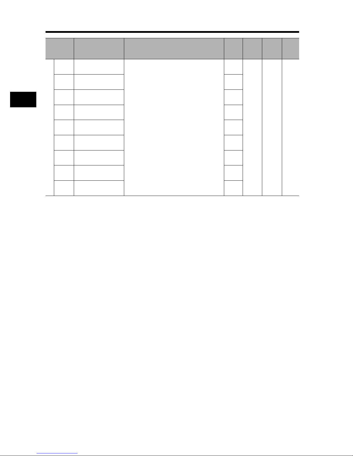
3-7 Parameter List
3
Operation
00
00
00
00
00
00
00
00
00
Changes
during
operation
No 4-79
Unit Page
Parameter
No.
C011
C012
C013
C014
C015
C016
Multi-function input terminals
C017
C018
C019
Function name Monitor or data range
Multi-function input 1
operation selection
Multi-function input 2
operation selection
Multi-function input 3
operation selection
Multi-function input 4
operation selection
Multi-function input 5
operation selection
Multi-function input 6
operation selection
Multi-function input 7
operation selection
Multi-function input 8
operation selection
FW terminal
operation selection
00: NO
01: NC
Default
setting
* 2nd/3rd control is displayed when "SET(08)/SET3(17)" is allocated to one of multi-function inputs from C001
to C008.
3-39
Page 89

3-7 Parameter List
00
01
03
07
40
05
Changes
during
Unit Page
operation
No 4-93
Parameter
No.
C021
C022
C023
C024
Multi-function output terminal
C025
C026
Function name Monitor or data range
00: RUN (signal during RUN)
01: FA1 (constant speed arrival signal)
Multi-function output
terminal
11 selection
Multi-function output
terminal 12 selection
Multi-function output
terminal 13 selection
Multi-function output
terminal 14 selection
Multi-function output
terminal 15 selection
Relay output (AL2,
AL1) function
selection
02: FA2 (over set frequency arrival signal)
03: OL (overload warning)
04: OD (excessive PID deviation)
05: AL (alarm output)
06: FA3 (set-frequency-only arrival signal)
07: OTQ (overtorque)
signal during momentary power interruption
08: IP (
09: UV (signal during undervoltage)
10: TRQ (torque limit)
11: RNT (RUN time over)
12: ONT (Power ON time over)
13: THM (thermal warning)
19: BRK (brake release)
20: BER (brake error)
21: ZS (0 Hz signal)
22: DSE (excessive speed deviation)
23: POK (position ready)
24: FA4 (set frequency exceeded 2)
25: FA5 (set frequency only 2)
26: OL2 (overload warning 2)
27: ODc (analog O disconnection detection)
28: OIDc (analog OI disconnection detection)
29: O2Dc (
31: FBV (PID FB status output)
32: NDc (network error)
33: LOG1 (logic operation output 1)
34: LOG2 (logic operation output 2)
35: LOG3 (logic operation output 3)
36: LOG4 (logic operation output 4)
37: LOG5 (logic operation output 5)
38: LOG6 (logic operation output 6)
39: WAC (capacitor life warning signal)
40: WAF (cooling fan life warning signal)
41: FR (starting contact signal)
42: OHF (fin overheat warning)
43: LOC (light load detection signal)
44: Not used
45: Not used
46: Not used
47: Not used
48: Not used
49: Not used
50: IRDY (operation ready signal)
51: FWR (forward run signal)
52: RVR (reverse run signal)
53: MJA (fatal fault signal)
54: WCO (window comparator O)
55: WCOI (window comparator OI)
56: WCO2 (window comparator O2)
(When C062 is used to select the alarm code
output, the multi-function output terminals 11 to
13, or 11 to 14 are forcibly changed to AC0 to
AC2 or AC0 to AC3 [Acn 'Alarm code output'],
respectively.)
analog O2 disconnection detection
Default
setting
)
)
* 2nd/3rd control is displayed when "SET(08)/SET3(17)" is allocated to one of multi-function inputs from C001
to C008.
3
Operation
3-40
Page 90

3-7 Parameter List
3
Operation
Parameter
No.
C027 FM selection
C028 AM selection
Analog monitor
C029 AMI selection
Digital current
C030
monitor reference
value
Function name Monitor or data range
00: Output frequency
01: Output current
02: Output torque
03: Digital output frequency
04: Output voltage
05: Input voltage
06: Thermal load rate
07: LAD frequency
08: Digital current monitor
09: Motor temperature
10: Fin temperature
12: Not used
00: Output frequency
01: Output current
02: Output torque
04: Output voltage
05: Input voltage
06: Thermal load rate
07: LAD frequency
09: Motor temperature
10: Fin temperature
11: Output torque <signed>
13: Not used
00: Output frequency
01: Output current
02: Output torque
04: Output voltage
05: Input voltage
06: Thermal load rate
07: LAD frequency
09: Motor temperature
10: Fin temperature
14: Not used
0.20 × Rated current to 2.00 × Rated current
(Current value at the digital current monitor
output 1440 Hz)
Default
setting
Rated
current
Changes
during
operation
00 No
00 No
00 No
Yes A 4-107
Unit Page
4-107
4-116
4-108
4-116
* 2nd/3rd control is displayed when "SET(08)/SET3(17)" is allocated to one of multi-function inputs from C001
to C008.
3-41
Page 91

3-7 Parameter List
Parameter
No.
C031
C032
C033
C034
Multi-function output terminal
C035
C036
C038
C039
C040
C041
C042
C043
Level and output terminal status
C044
C045
C046
C052
C053
Function name Monitor or data range
Multi-function output
terminal 11 contact
selection
Multi-function output
terminal 12 contact
selection
Multi-function output
terminal 13 contact
selection
Multi-function output
terminal 14 contact
selection
Multi-function output
terminal 15 contact
selection
Relay output (AL2,
AL1) contact
selection
Light load signal
output mode
Light load detection
level
Overload warning
signal output mode
Overload warning
level
Arrival frequency
during acceleration
Arrival frequency
during deceleration
PID deviation
excessive level
Arrival frequency
during acceleration 2
Arrival frequency
during deceleration 2
PID FB upper limit
PID FB lower limit
00: NO contact at AL2; NC contact at AL1
01: NC contact at AL2; NO contact at AL1
00: Enabled during acceleration/deceleration/
constant speed
01: Enabled only during constant speed
0.0 to 2.00 × Rated current (0.4 to 55 kW)
0.0 to 1.80 × Rated current (75 to 132 kW)
00: Enabled during acceleration/deceleration/
constant speed
01: Enabled only during constant speed
0.0: Does not operate.
0.1 × Rated current to 2.00 × Rated current
(0.4 to 55 kW)
0.1 × Rated current to 1.80 × Rated current
(75 to 132 kW)
0.00 to 99.99
100.0 to 400.0
0.00 to 99.99
100.0 to 400.0
0.0 to 100.0 3.0 No % 4-31
0.00 to 99.99
100.0 to 400.0
0.00 to 99.99
100.0 to 400.0
0.0 to 100.0
0.0 to 100.0 0.0 No %
Default
setting
Rated
current
Rated
current
100.0
Changes
during
operation
00
No 4-94
01
01 No
No A
01 No
No A
0.00 No Hz
0.00 No Hz
0.00 No Hz
0.00 No Hz
No %
Unit Page
4-104
4-49
4-96
4-96
4-31
* 2nd/3rd control is displayed when "SET(08)/SET3(17)" is allocated to one of multi-function inputs from C001
to C008.
3
Operation
3-42
Page 92

3-7 Parameter List
3
Operation
Parameter
No.
C055
C056
C057
C058
C061
Level and output terminal status
C062 Alarm code selection
C063 0 Hz detection level
C064
C071
C072
C073
C074
C075
Communication function
C076
C077
C078
C079
Function name Monitor or data range
Overtorque level
(Forward power
running)
Overtorque level
(Reverse
regeneration)
Overtorque level
(Reverse power
running)
Overtorque level
(Forward
regeneration)
Thermal warning
level
Fin overheat warning
level
Communication
speed selection
(Baud rate selection)
Communication
station No. selection
Communication bit
length selection
Communication
parity selection
Communication stop
bit selection
Communication error
selection
Communication error
timeout
Communication wait
time
Communication
method selection
Default
setting
0. to 200. (0.4 to 55 kW)
0. to 180. (75 to 132 kW)
0. to 100. 80. No % 4-46
00: Disabled
01: 3-bit
02: 4-bit
0.00 to 99.99
100.0
0. to 200. 120. No C4-103
02: Loop-back test
03: 2400 bps
04: 4800 bps
05: 9600 bps
06: 19200 bps
1. to 32. 1. No
7: 7-bit
8: 8-bit
00: No parity
01: Even
02: Odd
1: 1-bit
2: 2-bit
00: Trip
01: Trip after deceleration stop
02: Ignore
03: Free-run stop
04: Deceleration stop
0.00 to 99.99 0.00 No s
0. to 1000. 0. No ms
00: ASCII
01: ModBus-RTU
Changes
during
operation
100. No %
100. No %
100. No %
100. No %
00 No 4-99
0.00 No Hz 4-99
04 No
7No
00 No
1No
02 No
01 No
Unit Page
4-98
4-140
4-102
4-140
4-140
* 2nd/3rd control is displayed when "SET(08)/SET3(17)" is allocated to one of multi-function inputs from C001
to C008.
3-43
Page 93

3-7 Parameter List
Parameter
No.
C081 O adjustment
C082 OI adjustment
C083 O2 adjustment
Adjustment
C085
C091 Not used
C101 UP/DWN selection
C102 Reset selection
Others
C103
C105 FM gain setting 50. to 200. 100. Yes % 4-108
C106 AM gain setting 50. to 200. 100. Yes %
C107 AMI gain setting 50. to 200. 100. Yes %
C109 AM bias setting 0. to 100. 0. Yes %
Meter adjustment
C110 AMI bias setting 0. to 100. 20. Yes %
Function name Monitor or data range
0. to 9999.
1000 to 6553 (10000 to 65530)
0. to 9999.
1000 to 6553 (10000 to 65530)
0. to 9999.
1000 to 6553 (10000 to 65530)
Thermistor
adjustment
Reset frequency
matching selection
0.0 to 999.9
1000.
Use "00".
* Do not change.
00: Do not store the frequency data
01: Store the frequency data
00: Trip reset at power-on
01: Trip reset when the power is OFF
02: Enabled only during trip (Reset when the
power is ON)
03: Trip reset only
00: 0 Hz start
01: Frequency matching start
02: Active Frequency Matching restart
Default
setting
Factory
default
Factory
default
Factory
default
Factory
default
Changes
during
operation
Yes
Yes
Yes
Yes 4-73
00 No
00 No 4-88
00 Yes
00 No 4-85
Unit Page
3
Operation
4-85
4-132
4-109
C111
Terminal
C121 O zero adjustment
Adjustment
C123 O2 zero adjustment
Overload warning
level 2
0.0 to 2.00 × Rated current (0.4 to 55 kW)
0.0 to 1.80 × Rated current (75 to 132 kW)
0. to 9999.
1000 to 6553 (10000 to 65530)
0. to 9999.
1000 to 6553 (10000 to 65530)
0. to 9999.
1000 to 6553 (10000 to 65530)
Rated
current
Factory
default
Factory
default
Factory
default
No A 4-49
Yes
Yes
Yes
C122 OI zero adjustment
* 2nd/3rd control is displayed when "SET(08)/SET3(17)" is allocated to one of multi-function inputs from C001
to C008.
3-44
Page 94

3-7 Parameter List
3
Operation
00
00
00
00
00
00
00
00
00
00
Changes
during
operation
No s 4-106
No 4-100
Unit Page
Parameter
No.
C130 Output 11 ON delay 0.0 to 100.0 0.0
C131 Output 11 OFF delay 0.0 to 100.0 0.0
C132 Output 12 ON delay 0.0 to 100.0 0.0
C133 Output 12 OFF delay 0.0 to 100.0 0.0
C134 Output 13 ON delay 0.0 to 100.0 0.0
C135 Output 13 OFF delay 0.0 to 100.0 0.0
C136 Output 14 ON delay 0.0 to 100.0 0.0
C137 Output 14 OFF delay 0.0 to 100.0 0.0
C138 Output 15 ON delay 0.0 to 100.0 0.0
C139 Output 15 OFF delay 0.0 to 100.0 0.0
C140
C141
Output terminal operation function
C142
C143
C144
C145
C146
C147
C148
C149
Output terminal operation function
C150
C151
Function name Monitor or data range
Relay output ON delay
Relay output OFF
delay
Logic output signal 1
selection 1
Logic output signal 1
selection 2
Logic output signal 1
operator selection
Logic output signal 2
selection 1
Logic output signal 2
selection 2
Logic output signal 2
operator selection
Logic output signal 3
selection 1
Logic output signal 3
selection 2
Logic output signal 3
operator selection
Logic output signal 4
selection 1
0.0 to 100.0 0.0
0.0 to 100.0 0.0
Same as options for C021 to C026
(excluding LOG1 to LOG6)
Same as options for C021 to C026
(excluding LOG1 to LOG6)
00: AND
01: OR
02: XOR
Same as options for C021 to C026
(excluding LOG1 to LOG6)
Same as options for C021 to C026
(excluding LOG1 to LOG6)
00: AND
01: OR
02: XOR
Same as options for C021 to C026
(excluding LOG1 to LOG6)
Same as options for C021 to C026
(excluding LOG1 to LOG6)
00: AND
01: OR
02: XOR
Same as options for C021 to C026
(excluding LOG1 to LOG6)
Default
setting
* 2nd/3rd control is displayed when "SET(08)/SET3(17)" is allocated to one of multi-function inputs from C001
to C008.
3-45
Page 95

3-7 Parameter List
00
00
00
00
00
00
00
00
Changes
during
operation
No 4-100
No ms 4-106
Unit Page
4-16
4-132
Parameter
No.
C152
C153
C154
C155
C156
C157
Output terminal operation function
C158
C159
C160
C161
C162
C163
C164
C165
Input terminal response
C166
C167
C168
C169
Others
Function name Monitor or data range
Logic output signal 4
selection 2
Logic output signal 4
operator selection
Logic output signal 5
selection 1
Logic output signal 5
selection 2
Logic output signal 5
operator selection
Logic output signal 6
selection 1
Logic output signal 6
selection 2
Logic output signal 6
operator selection
Input terminal
response time 1
Input terminal
response time 2
Input terminal
response time 3
Input terminal
response time 4
Input terminal
response time 5
Input terminal
response time 6
Input terminal
response time 7
Input terminal
response time 8
FW terminal response
time
Multi-step speed/
position
determination time
Same as options for C021 to C026
(excluding LOG1 to LOG6)
00: AND
01: OR
02: XOR
Same as options for C021 to C026
(excluding LOG1 to LOG6)
Same as options for C021 to C026
(excluding LOG1 to LOG6)
00: AND
01: OR
02: XOR
Same as options for C021 to C026
(excluding LOG1 to LOG6)
Same as options for C021 to C026
(excluding LOG1 to LOG6)
00: AND
01: OR
02: XOR
0. to 200. (× 2 ms) 1
0. to 200. (× 2 ms) 1
0. to 200. (× 2 ms) 1
0. to 200. (× 2 ms) 1
0. to 200. (× 2 ms) 1
0. to 200. (× 2 ms) 1
0. to 200. (× 2 ms) 1
0. to 200. (× 2 ms) 1
0. to 200. (× 2 ms) 1
0. to 200. (× 10 ms) 0 No ms
Default
setting
* 2nd/3rd control is displayed when "SET(08)/SET3(17)" is allocated to one of multi-function inputs from C001
to C008.
3
Operation
3-46
Page 96

3-7 Parameter List
3
Operation
Parameter
No.
H001 Auto-tuning selection
H002
H202
H003
H203
Control parameter
H004
H204
H005 Speed response
H205 * 2nd speed response 1.590
Function name Monitor or data range
00: Disabled
01: Not rotate
02: Rotate
Motor parameter
selection
* 2nd motor
parameter selection
Motor capacity
selection
* 2nd motor capacity
selection
Motor pole number
selection
* 2nd motor pole
number selection
00: Standard motor parameter
01: Auto-tuning parameter
02: Auto-tuning parameter
(online auto-tuning enabled)
0.20 to 160.0
2/4/6/8/10
0.001 to 9.999/10.00 to 80.00
(10.000 to 80.000)
Default
setting
Factory
default
Factory
default
1.590
Changes
during
operation
00 No 4-109
00
No
00
No kW
4
No Pole
4
Yes
Unit Page
4-109
4-111
4-113
4-19
4-109
4-113
4-116
4-87
4-90
* 2nd/3rd control is displayed when "SET(08)/SET3(17)" is allocated to one of multi-function inputs from C001
to C008.
3-47
Page 97

3-7 Parameter List
100.
100.
100.
on the
motor
on the
motor
on the
motor
on the
motor
on the
motor
on the
motor
on the
motor
on the
motor
on the
motor
on the
motor
Changes
during
operation
Yes 4-118H206
No
No
No mH
No A
No kgm
Unit Page
4-113
4-113
2
Parameter
No.
H006
H306
H020 Motor parameter R1
H220
H021 Motor parameter R2
H221
H022 Motor parameter L
Control parameter
H222
H023 Motor parameter Io
H223
H024 Motor parameter J
H224
Function name Monitor or data range
Stabilization
parameter
* 2nd stabilization
parameter
* 3rd stabilization
parameter
* 2nd motor
parameter R1
* 2nd motor
parameter R2
* 2nd motor
parameter L
* 2nd motor
parameter Io
* 2nd motor
parameter J
0. to 255.
0.001 to 9.999
10.00 to 65.53
0.001 to 9.999
10.00 to 65.53
0.01 to 99.99
100.0 to 655.3
0.01 to 99.99
100.0 to 655.3
0.001 to 9.999
10.00 to 99.99
100.0 to 999.9
1000. to 9999.
Default
setting
Depends
capacity.
Depends
capacity.
Depends
capacity.
Depends
capacity.
Depends
capacity.
Depends
capacity.
Depends
capacity.
Depends
capacity.
Depends
capacity.
Depends
capacity.
* 2nd/3rd control is displayed when "SET(08)/SET3(17)" is allocated to one of multi-function inputs from C001
to C008.
3
Operation
3-48
Page 98

3-7 Parameter List
3
Operation
on the
motor
on the
motor
on the
motor
on the
motor
on the
motor
on the
motor
on the
motor
on the
motor
on the
motor
on the
motor
Changes
during
operation
No
No
No mH
No A
No kgm
Unit Page
4-109
4-113
2
Parameter
No.
H030
H230
H031
H231
H032
H232
Control parameter
H033
H233
H034
H234
Motor parameter R1
(auto-tuning data)
* 2nd motor
parameter R1
(auto-tuning data)
Motor parameter R2
(auto-tuning data)
* 2nd motor
parameter R2
(auto-tuning data)
Motor parameter L
(auto-tuning data)
* 2nd motor
parameter L
(auto-tuning data)
Motor parameter Io
(auto-tuning data)
* 2nd motor
parameter Io
(auto-tuning data)
Motor parameter J
(auto-tuning data)
* 2nd motor
parameter J
(auto-tuning data)
Function name Monitor or data range
0.001 to 9.999
10.00 to 65.53
0.001 to 9.999
10.00 to 65.53
0.01 to 99.99
100.0 to 655.3
0.01 to 99.99
100.0 to 655.3
0.001 to 9.999
10.00 to 99.99
100.0 to 999.9
1000. to 9999.
Default
setting
Depends
capacity.
Depends
capacity.
Depends
capacity.
Depends
capacity.
Depends
capacity.
Depends
capacity.
Depends
capacity.
Depends
capacity.
Depends
capacity.
Depends
capacity.
* 2nd/3rd control is displayed when "SET(08)/SET3(17)" is allocated to one of multi-function inputs from C001
to C008.
3-49
Page 99

3-7 Parameter List
Parameter
No.
H050 PI proportional gain
H250
H051 PI integral gain
H251 *2nd PI integral gain 100.0
H052 P proportional gain
H252
H060 Limit at 0 Hz
H260 * 2nd limit at 0 Hz 100.0
H061
Control parameter
H261
H070
H071
H072
H073 Gain switching time 0. to 9999. 100. Yes ms
P001
P002
P011 Encoder pulses
P012
Options
P013
P014
P016
Function name Monitor or data range
* 2nd PI proportional
gain
*2nd P proportional
gain
Boost amount at SLV
startup, 0 Hz
* 2nd boost amount at
SLV startup, 0 Hz
For PI proportional
gain switching
For PI integral gain
switching
For P proportional
gain switching
Operation selection
at option 1 error
Operation selection
at option 2 error
V2 control mode
selection
Pulse train mode
selection
Orientation stop
position
Orientation speed
setting
Orientation direction
setting
0.0 to 999.9
1000.
0.0 to 999.9
1000.
0.01 to 10.00
0.0 to 100.0
0. to 50.
0.0 to 999.9
1000.
0.0 to 999.9
1000.
0.00 to 10.00 1.00 Yes
00: Trip
01: Continues operation
00: Trip
01: Continues operation
128. to 9999.
1000 to 6500 (10000 to 65000)
00: ASR (speed control mode)
01: APR (pulse train position control mode)
02: APR2 (absolute position control mode)
03: HAPR (High resolution absolute position
control mode)
00: Mode 0
01: Mode 1
02: Mode 2
0. to 4095. 0. No
Starting frequency to Max. frequency (upper
limit: 120.0)
00: Forward side
01: Reverse side
Default
setting
100.0
100.0
100.0
100.0
100.0 Yes
100.0 Yes
1024.
Changes
during
operation
Yes
Yes
1.00
Yes
1.00
Yes %
50.
Yes %
50.
00 No
00 No
No Pulse
00 No
00 No 4-123
5.00 No Hz
00 No
Unit Page
4-87
4-90
4-115
4-87
4-109
4-120
4-128
4-129
4-120
4-131
4-129P015
* 2nd/3rd control is displayed when "SET(08)/SET3(17)" is allocated to one of multi-function inputs from C001
to C008.
3
Operation
3-50
Page 100

3-7 Parameter List
3
Operation
Parameter
No.
P017
P018
P019
P020
P021
P022
P023 Position loop gain
P024 Position bias amount -204(-2048.)/-999. to 2048. 0. Yes 4-124
P025
Options
P026
P027
P028
P029
P031
P032
P033
P034
P035
Function name Monitor or data range
Position ready range
setting
Position ready delay
time setting
Electronic gear
setting position
selection
Electronic gear ratio
numerator
Electronic gear ratio
denominator
Position control
feedforward gain
Secondary resistance
compensation
enable/disable
selection
Overspeed error
detection level
Speed deviation error
detection level
Motor gear ratio
numerator
Motor gear ratio
denominator
Acceleration/
deceleration time
input type
Orientation stop
position input type
Torque reference
input selection
Torque reference
setting
Polarity selection at
torque reference via
O2
0. to 9999.
1000(10000)
0.00 to 9.99 0.00 No s
00: Position feedback side (FB)
01: Position command side (REF)
0. to 9999. 1. No
0. to 9999. 1. No
0.00 to 99.99
100.0 to 655.3
0.00 to 99.99
100.0
00: Disabled
01: Enabled
0.0 to 150.0 135.0 No % 5-6
0.00 to 99.99
100.0 to 120.0
1. to 9999. 1. No
1. to 9999. 1. No
00: Digital Operator
01: Option 1
02: Option 2
00: Digital Operator
01: Option 1
02: Option 2
00: Terminal O
01: Terminal OI
02: Terminal O2
03: Digital Operator
0. to 200. (0.4 to 55 kW)
0. to 180. (75 to 132 kW)
00: Signed
01: Depends on the RUN direction
Default
setting
Changes
during
operation
5. No Pulse
00 No
0.00 No
0.50 No rad/s
00 No 4-112
7.50 No Hz 4-120
00 No 4-8
00 No
00 No
0. Yes %
00 No
Unit Page
4-123
4-129
4-123
4-129
4-123
4-125
4-120
4-124
4-125
4-129
4-131
4-128
4-122
* 2nd/3rd control is displayed when "SET(08)/SET3(17)" is allocated to one of multi-function inputs from C001
to C008.
3-51
 Loading...