

Page 1
I823-E1-01
Servo System 1S-series
Startup Guide
R88M-1L[]/-1M[] (AC Servomotors)
R88D-1SN[]-ECT (AC Servo Drives)
Page 2

NOTE
All rights reserved. No part of this publication may be reproduced, stored in a retriev al system,
or transmitted, in any for m , or by any means, mechanica l, phot ocopying, recording, or
otherwise, without the prio r w r it t en per m iss ion of OMRON.
No patent liability is assume d with respect to the use of the i nf ormation contained herein.
Moreover, because OMRON is constantly striving to improv e it s high-quality pr oduct s, the
information contained in t his manual is subject to change w ithout notice. Every pr ecaut ion has
been taken in the preparation o f this manual. Nevertheless, OMRON assumes no
responsibility for errors or omissions. Neither is any liability assumed for da mages resulting
from the use of the informat ion contained in this publication.
2
Page 3

Introduction
The Servo System 1S-Series Star t up Guide (hereinafter, may be referred to as "this Guide")
describes the procedures for installation and setup of a 1S Servo Drive, where an
NJ/NX-series CPU Unit is used in combination with1S-series AC Servomotors/Serv o Driv es and
NX-series Safety Unit, by using the Sysmac Stud io. A simple installation model is used for t he
discussion. You can perform the proced ur es t hat ar e presented in this Guide to quickly gain a
basic understanding of a 1S-series AC Servomotors/ Ser vo Drives.
This Guide does not contain sa fety infor mation and ot her detai ls that are requ ir ed for actu al us e.
Thoroughly read and u nderstand t he manua ls for all of the device s that are u sed in th is Guide t o
ensure that the system is used safely. Review the entire contents of these mater ial s, including
all safety precautions, precautions for safe use, and precautions for correct us e.
Intended Audience
This Guide is intended for t he following personnel.
• Personnel in charge of introducing FA systems
• Personnel in charge of de signing FA systems
The personnel must also hav e t he following knowledge.
• Knowledge of electrical sy s t em s ( an el ectrical engineer or the equivalent)
• Knowledge of NJ/NX-series CP U Units
• Knowledge of NX-series Safety Units
• Knowledge of Servomotors/Drives
• Knowledge of operation pr ocedure of Sysmac Studio
Applicable Products
This Guide covers the foll ow ing products.
• CPU Units of NJ/NX-series Machine Automation Controllers
• Automation Software Sy smac Studio
• 1S-series Servomotors/Se rv o Drives
• NX-series EtherCAT Coupler unit
• NX-series Safety controlle r
Special Information
The icons that are used in this G uid e ar e described below.
Precautions for Correct Use
Precautions on what to do and what not to do to ensure proper o per at i on and
performance.
Additional Inf or mation
Additional information to read as required.
This information is provid ed to increase understandi ng or m ake operation easi er.
3
Page 4

Terms and Conditions Agreement
Warranties
(a) Exclusive Warranty . Omro n’s exclusive warranty is that the Products will be free fro m
defects in materials and w or km anship for a period of twelve months from the date of sale by
Omron (or such other period expressed in writing by Omron). Omron disc laims all other
warranties, express or implied.
(b) Limitations. OMRON MAKES NO WARRANTY OR REPRESENTATION, EXPRESS OR
IMPLIED, ABOUT NON-INFRINGEMENT, MERCHANTABILITY OR FITNESS FOR A
PARTICULAR PURPOSE OF THE PRODUCTS. BUYER ACKNOWLEDGES THAT IT ALONE
HAS DETERMINED THAT THE PRODUCTS WILL SUI TA BLY MEE T THE R EQUIREMENTS
OF THEIR INTENDED USE.
Omron further disclaims a l l w ar r ant ies and responsibility of any type for claims or expenses
based on infringement by the Products or otherwise of any int ellectual property r ight. ( c ) Buyer
Remedy.
Omron’s sole obligation hereunder shall be, at Omron’s election, to (i) replace (in the form
originally shipped with Buy er r esponsible for labor charges for removal or replacement ther eof)
the non-complying Product , (ii) repair the non-complying Product, or (iii) repay or cr edit Buyer
an amount equal to the pur chase price of the non-complying Product; provided that in no event
shall Omron be respons ibl e for w ar r ant y, repair, indemnity or any other claims or expenses
regarding the Products unless Omron’s analysis con fir ms that the Products were properly
handled, stored, installed and maintained and not subject to contamination, abuse, misuse or
inappropriate modification. Return of any Product s by Buyer must be approved in writing by
Omron before shipment. O mron Companies shall not be li abl e for t he suitability or unsuitability
or the results from the use of Products in combinatio n with any electrical or electr onic
components, circuits, system asse mblies or any other materials or substances or environments .
Any advice, recommend at ions or information g iv en or ally or in writing, are not to be c onst r ued
as an amendment or addition to t he above warranty.
See http://www.omron.com/global/
information.
Limitation on Liability; Etc
OMRON COMPANIES SHALL NOT BE LI ABLE FOR SPECIAL, INDIRECT, INCIDENTAL, OR
CONSEQUENTIAL DAMAGES, LOS S OF PROFITS OR PRODUCTION OR COMMERCI A L
LOSS IN ANY WAY CONNECTED WITH THE PRODUCTS, WHETHER SUCH CLAIM IS
BASED IN CONTRACT, WARRANTY, NEGLIGENCE OR STRICT LIABILITY.
Further, in no event shall liabil ity of Omron Companies exceed the individual p r ice of the
Product on which liability is asserted.
Suitability of Use
Omron Companies shall n ot be r esponsible for conformity with any standards, codes or
regulations which apply t o the combination of the Product in the Buyer’s applicat ion or use of
the Product. At Buyer’s request, Omron will provid e applicable third party cer tification
4
or contact your Omro n r epr esentative for published
Page 5

documents identifying rati ngs and limitations of use which apply to the Product . This infor matio n
by itself is not sufficient for a complete determinati on of the suitability of the Product in
combination with the end pr oduct, machine, system, or ot her application or use. Buyer shal l be
solely responsible for dete r m ini ng appropriateness of the particular Product with respect t o
Buyer’s application, pr oduct or system. Buyer shall take application responsibility in all cases.
NEVER USE THE PRODUCT FOR AN APPLICATION IN VOLVING SERIOUS RISK TO LIFE
OR PROPERTY WIT HO U T ENSU RI NG TH A T THE SY ST EM AS A WHOLE H AS BE E N
DESIGNED TO ADDRESS THE RISKS , AND THA T THE OMRON PRODUCT(S ) IS
PROPERLY RATED AND INSTALLED FOR THE INTENDED USE WITHIN THE OVERALL
EQUIPMENT OR SY ST E M.
Programmable Products
Omron Companies shall n ot be r esponsible for the user’s programming of a programmable
Product, or any consequence thereof.
Performance Data
Data presented in Omron Company websites, catalogs and other materials is provided as a
guide for the user in deter m in ing suitability and does not constitute a warranty. It may represent
the result of Omron’s test c onditions, and the user mu st cor r el ate it to actual application
requirements. Actual performance is subject to t he O mron’s Warranty and Li m it at io ns of
Liability
Change in Specificati on s
Product specifications and accessories may be c hanged at any time based on improvements
and other reasons. It is o ur practice to change part numbers when publ ished ratings or features
are changed, or when significant construction changes are made. However, some
specifications of the Product may be changed without any notice. When in doubt, special part
numbers may be assigned to fix or establish key specific at i ons for your application. Plea se
consult with your Omron’s representative at any time to confirm actual specif i cat ions of
purchased Product.
Errors and Omissions
Information presented by Omron Compan ies has been checked and i s believed to be accurate;
however, no responsibi lity is assumed for cler ical, typographical or proo freading errors or
omissions.
5
Page 6

Precautions
• When building a syste m, check the specifications for all devices and equipment that will make
up the system and make sur e t hat the OMRON products are use d w ell within their rated
specifications and performances. Safety measures, such as safety circuits, must be
implemented in order to m inim ize the risks in the event of a malfunction.
• Thoroughly read and understand the manuals for all devices and equipment t hat will make up
the system to ensure that the system is used safely. Review the entire contents of these
manuals, including all saf ety precautions, prec aution s for safe use, and precau tions for corr ect
use.
• Confirm all regulations, standards, and restrictions that the system must adhere to.
• Check the user progra m f or pr oper execution before you use it for act ual operation.
Trademarks
• Sysmac and SYSMAC are trademarks or regist er ed trademarks of OMRON Corporation in
Japan and other countries for O M RON factory automation products.
• Windows is either registered trademarks or tr ademarks of Microsoft Corpor ation in the USA
and other countries.
• EtherCAT
GmbH, Germany.
• Microsoft product screen shot(s) reprinted with perm ission from Microsoft Co r por at ion.
• Other company names and product names in this Guide are the trademarks or r egister ed
trademarks of their respe ctive companies.
Software Licenses and Copyrights
®
is registered tr ade mark and pat ented t echno logy, licensed by Beckhoff Automation
The NJ-series CPU Units and Sysmac Studio incorporate certain third party s oftw ar e. The
license and copyright infor mation associated w it h t hi s softw ar e is available at
http://www.fa.omron.co.jp/nj_info_e/.
6
Page 7

Related Manuals
The following manuals are related. Use t hese manuals for reference.
Manual name Cat. No. Model Application Description
Sysmac Studio Version 1
Operation Manual
Sysmac Studio Drive
Functions Operation
Manual
NJ-series CPU Unit
Hardware User´s Manual
NJ/NX-series CPU Unit
Software User’s Manual
NJ/NX-series CPU Unit
Motion Control User's
Manual
NJ/NX-series Instructions
Reference Manual
W504 SYSMAC-SE2□□□ Learning about the operating
procedures and functions of
the Sysmac Studio.
I589-E1 SYSMAC-SE2□□□ Learning about the operating
procedures and functions of
the Sysmac Studio for Drives
W500 NJ501-□□□□
NJ301-□□□□
W501 NJ501-□□□□
NJ301-□□□□
W507 NJ501-□□□□
NJ301-□□□□
NJ101-□□□□
W502 NJ501-□□□□
NJ301-□□□□
Learning the basic
specifications of the
NJ-series CPU Units,
including introductory
information, designing,
installation, and
maintenance.
Mainly hardware information
is provided.
Learning how to program and
set up an NJ/NX-series CPU
Unit.
Mainly software information is
provided.
Learning about motion
control settings and
programming concepts.
Learning detailed
specifications on the basic
instructions of an
NJ/NX-series CPU Unit.
Describes the operating procedures of
the Sysmac Studio.
Describes the operating procedures of
the Sysmac Studio to setup Drives
Provides an introduction to the entire
NJ-series system along with the
following information on the CPU Unit.
• Features and system configuration
• Overview
• Part names and functions
• General specifications
• Installation and wiring
• Maintenance and inspection
Use this manual together with the
NJ/NX-series CPU Unit Software
User's Manual (Cat. No. W501).
Provides the following information on a
Controller built with an NJ/NX-series
CPU Unit.
• CPU Unit operation
• CPU Unit features
• Initial settings
• Language specifications and
programming based on IEC 61131-3
Use this manual together with the
NJ-series CPU Unit Hardware User's
Manual (Cat. No. W500).
Describes the settings and operation of
the CPU Unit and programming
concepts for motion control.
When programming, use this manual
together with the NJ-series CPU Unit
Hardware User's Manual (Cat . No .
W500) and NJ/NX-series CPU Unit
Software User's Manual (Cat. No.
W501).
Describes the instructions in the
instruction set (IEC 61131-3
specifications).
When programming, use this manual
together with the NJ-series CPU Unit
Hardware User's Manual (Cat . No .
W500) and NJ/NX-series CPU Unit
Software User's Manual (Cat. No.
W501).
7
Page 8

Manual name
Cat. No.
Model
Application
Description
NJ/NX-series Motion
Control Instructions
Reference Manual
NJ/NX-series
Troubleshooting Manual
W508 NJ501-□□□□
NJ301-□□□□
W503 NJ501-□□□□
NJ301-□□□□
Learning about the
specifications of the motion
control instructions that are
provided by OMRON.
Learning about the errors
that may be detected in an
NJ/NX-series Controller.
Describes the motion control instructions.
When programming, use this manual
together with the NJ-series CPU Unit
Hardware User's Manual (Cat . No .
W500), NJ/NX-series CPU Unit Software
User's Manual (Cat. No. W501), and
NJ/NX-series CPU Unit Motion Control
User's Manual (Cat. No. W507).
Describes concepts on managing errors
that may be detected in an NJ/NX-series
Controller and information on individual
errors.
Use this manual together with the
NJ-series CPU Unit Hardware User's
Manual (Cat. No. W500) and
NJ/NX-series CPU Unit Software User's
Manual (Cat. No. W501).
NX-series Safety Control
Units User’s Manual
1S-series AC
Servomotors/Servo Drives
with Built-in EtherCAT
Communications User's
Manual
Z930 NX-SL□□□□
I586
NX-SI□□□□
NX-SO□□□□
R88D-1S□-ECT
R88M-1□
Learning how to use the
NX-series Safety Control
Units.
Learning detailed
specifications of a
1S-series Servo Drive.
Describe the hardware, setup methods
and functions of the NX-series Safety
Control Units.
Describes how to install and wire the
Servo Drive, set parameters needed to
operate the Servo Drive, and remedies to
be taken and inspection methods to be
used in case that problems occur.
8
Page 9

Revision History
Cat. No.
A manual revision code appears a s a suffix to the catalog number on the front and back covers
of the manual.
Revision code Date Revised content
01 July 2016 Original production
I823-E1-01
Revision code
9
Page 10

CONTENTS
Introduction ······························································································ 3
Intended Audience ..................................................................................................... 3
Applicable Products ................................................................................................... 3
Special Information .................................................................................................... 3
T erms and Conditions Agreement ······························································· 4
Precautions ······························································································ 6
Trademarks ................................................................................................................ 6
Software Licenses and Copyrights ............................................................................ 6
Related Manuals ······················································································· 7
Revision History ······················································································· 9
1. Servo system configuration and peripheral products ···························· 11
1.1. Outline ............................................................................................................. 11
1.2. Servo System constructed in this guide .......................................................... 12
1.3. System c onfiguration ....................................................................................... 13
2. Before You Begin ·············································································· 15
3. Performing setup ·············································································· 16
3.1. Installat ion & Wiring ........................................................................................ 16
3.2. System c onfiguration with NJ and NX safety controller .................................. 24
3.3 Sysmac Studio project creation ...................................................................... 25
3.4 Motor, ABS Encoder and I/O Setup ................................................................ 29
3.5. Easy tuning for gain adjustment...................................................................... 33
3.6. FSoE STO activation ....................................................................................... 37
ANNEX ··································································································· 42
Add a drive and axis OFFLINE ................................................................................ 42
Test run and data trace ............................................................................................ 46
Manual tuning .......................................................................................................... 48
Advanced tuning ...................................................................................................... 52
10
Page 11

1. Servo system configuration and peripheral products
1.1. Outline
The 1S-series AC Servo Drives with Built-in EtherCAT communications support 100-Mbps EtherCAT.
When you use the 1S-series Servo Drive with a Machine Automation Controller NJ/NX-series CPU Unit or
CJ1W-NC
sophisticated positioning control system.
Also, you need only one communications cable to connect the Servo Drive and the Controller. Therefore,
you can realize a position control system easily with reduced wiring effort.
With auto tuning, adaptive filter, notch filter, and damping control, you can set up a system that provides
stable operation by suppressing vibration in low-rigidity machines.
The FSoE protocol, the technology for a safe communication layer supported by the 1S-series Servo
Drives, allows you to build the safety system that uses the STO function from the safety controller on the
EtherCAT network.
□8□ EtherCAT-compatible Position Control Unit, you can construct a high-speed and
Additional Inf or mation
For additional information about 1S servo drive, please refer to 1S-series AC Servomotors and Servo
Drives User’s Manual (with Built-in EtherCAT Communications) (Cat. No. I586)
11
Page 12

1.2. Servo System constructed in this guide
This 1S-series Sysmac AC Servo Drives Startup Guide (hereafter referred to as “this Guide”) contains
instructions from assembling the hardware that makes up the Servo system to performing debugging on
the system. This Guide builds the Servo system in the following steps
1 Installation and wiring
▼
2 System Configuration with NJ and NX sa fety controller
▼
3 Sysmac Studio project creation and sizi ng f il e i mp or t
▼
4 Motor, ABS encoder, I/O Setup
▼
5 Easy tuning for gain adjustment
▼
6 FSoE STO Activation
Additional Inf or mation
For additional information on how to setup the motion, please refer to the start-up guide for moti on
control (W514-E1-01).
12
Page 13
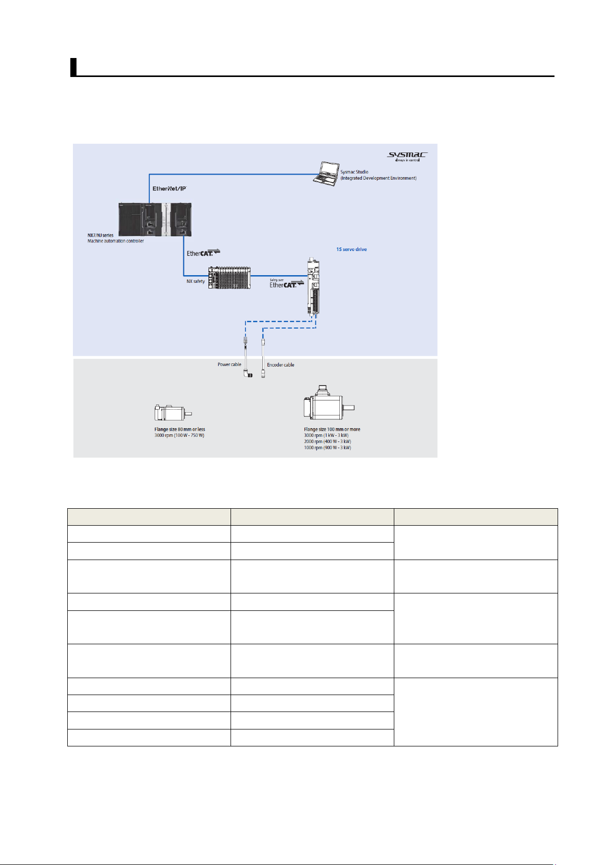
1.3. System configuration
in EtherCAT
The following figure shows the system configuration and devices that are used in this Guide.
The system configuration is shown in the following figure.
• Configuration devices
The models of the devices that are described in this Guide are given in the following table. When selecting
devices for an actual application, refer to the device manuals.
Device name Model Manual name
NJ-series CPU Unit NJ501-[] NJ-series CPU Unit Hardware
NJ-series Power Supply NJ-P[]3001
NX-series EtherCAT Coupler NX-ECC[] NX-series EtherCAT Coupler Unit
NX-series Safety control unit NX-SL3300 NX safety CPU unit Hardware
NX I/0 Series NX-SID[]
NX-SOD[]
Ethernet/EtherCAT
communications cables
AC Servo Drives R88D-1SN[] 1S-series AC Servomotors and
AC Servo Motors R88M-1[]
Power cables R88A-CA[]
Encoder Cables R88A-CR[]
XS5W-T[] -
User’s Manual (Cat. No. W500)
User’s Manual (Cat. No. W519)
User’s Manual (Cat. No. Z930)
Servo Drives User’s Man ua l ( with
BuiltCommunications) (Cat. No. I586)
13
Page 14

• Automation soft ware
Sysmac Studio Standard
Product Number of license Model
None (DVD only) SYSMAC-SE200D
Edition Ver s ion 1.16
From 1 license to site license SYSMAC-SE[]
14
Page 15
2. Before You Begin
1.
2.
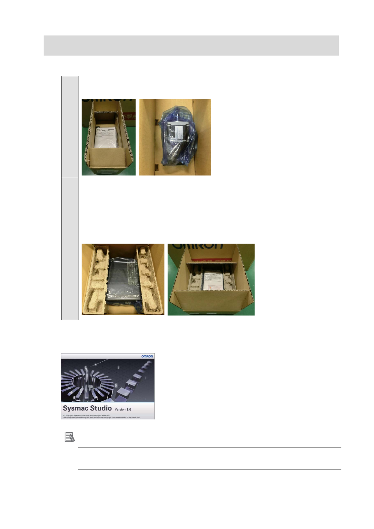
■ Unpack Drive/Motor
Unpack motor package. The package includes only motor and instructio n sheet.
Cables are provided separately.
Unpack drive package.
This product com es with the following access ories.
• INSTRUC TION MANUAL × 1 copy
• Warning la bel × 1 sheet
• General Compliance Information and instru ct i ons for EU × 1 copy
• Attached connectors
■ Install the Sysmac Studio Standard Edition
Refer to the Sysmac Studio Version 1 O per at ion Manual (Cat. No. W504) for how to instal l.
Additional Inf or mation
For further details on how to handle drive and motor package, please refer to 1S-series AC
Servomotors and Servo Driv es User’s Manual (with Built-in EtherCAT C ommun ic atio ns) (Cat. No. I586)
15
Page 16
3. Performing setup
℃
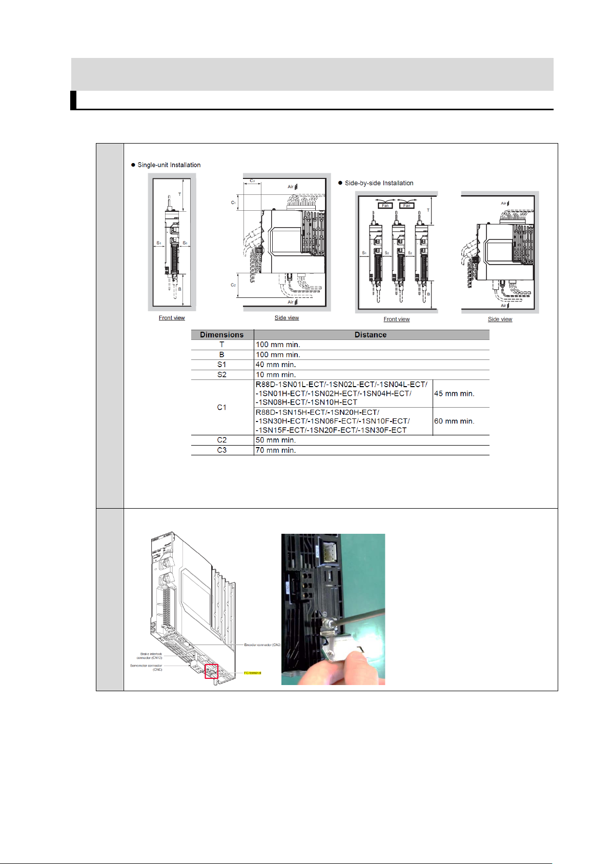
3.1. Installation & Wiring
■ Drive installation
Install the Servo Drive according to the following.
When installing side-by-side, S2 can be reduced to 0mm under so me co nditions:
temperature inside cabin et should be low er than 45
prevent uneven temperatu r es inside the cabinet/panel.
1.
In case of using the shiel d cl am p, please fixe it in advance with the existing screw
and i nstall a fan for air c irculation t o
16
Page 17
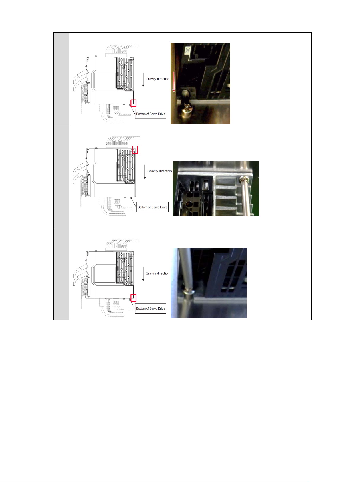
2.
Approach the drive from top to down.
3.
Tight the upper part.
4.
Tight the down part.
17
Page 18
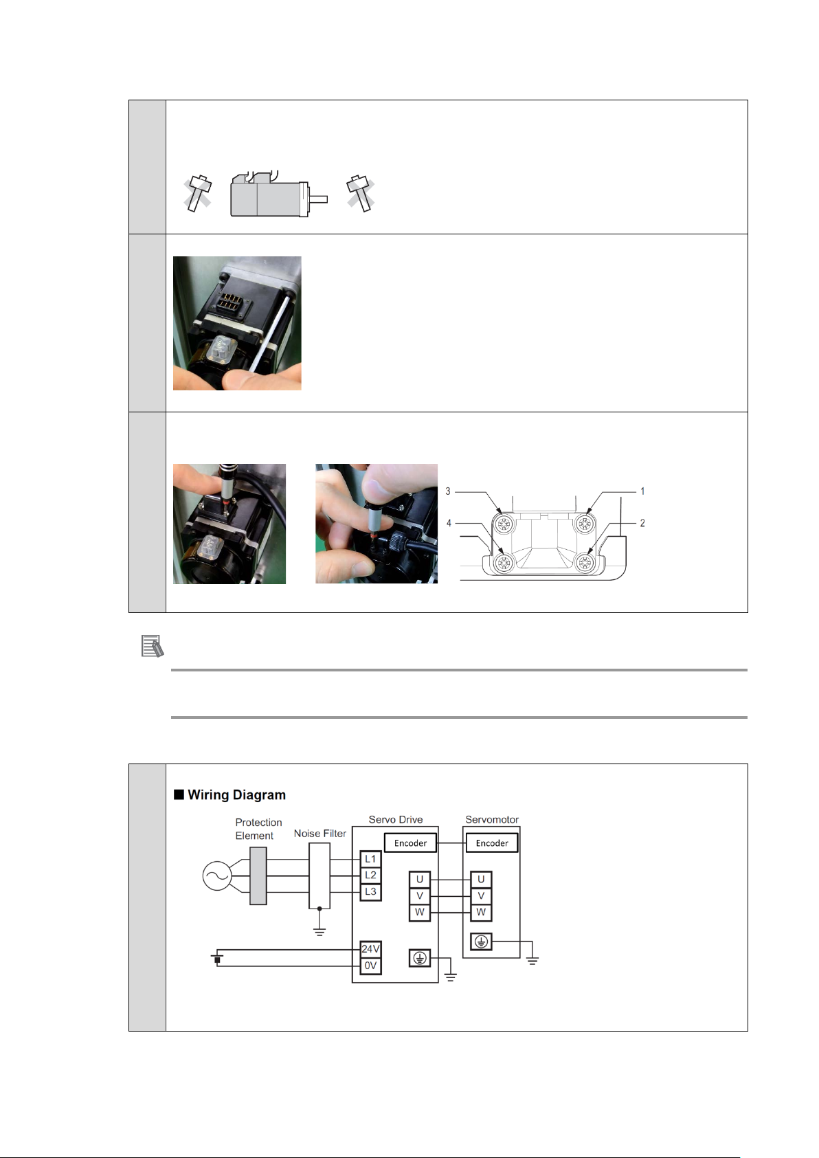
■ Motor installation
1.
Please handle the motor carefully & do not apply heavy impacts or loads during
transport, installation, or removal of the motor.
(step 2, 3 order depends on your mechanical implementation)
2. Please fixe and connect the motor to the mechanical system
Note: At first, please check motor operation without any load.
3.
Please attached the power and encoder cable
Here is an example with 200W motor
■ Wiring
1. Overview
Please tight screws in sev er al times in this order :1>4>3> 2
Additional Inf or mation
For further details about coupling method, please refer to 1S-series AC Servomotors and Servo Drives
User’s Manual (with Built-in EtherCAT Communications) (Cat. No. I586)
18
For further details please refer to section 4-2 wiring of 1S AC servo drive user’s manual
(Cat. No. I586)
Page 19

2.
Remove power connector(s) (CNA) or (CNA)/(CND) from the drive depending on
the model:
100V/200V (up to 1kW) 200V (1.5kW-3kW) 400V (0.6kW-3kW)
3.
Please wire the 24V control power supply (stripped wires or ferrules can be used)
Connect wires with the spr ing opener
Please refer to the corresponding connector depending on your drive and power s upply:
CNA for 100V/200V (up to 1kW) CND for 200V (1.5kW-3kW) 400V (0.6kW-3kW)
4.
Please wire the AC power supply
Please refer to the corresponding connector depending on your drive and AC power
supply type
1-Phase
100V/200V (up to 1k W) 200V (1.5kW)
3-Phase
200V (up to 1kW) 2 00V (1.5kW-3kW) 400V (0.6kW-3kW)
Example:(CNA) for 100V/200V (up to 1kW)
19
Page 20
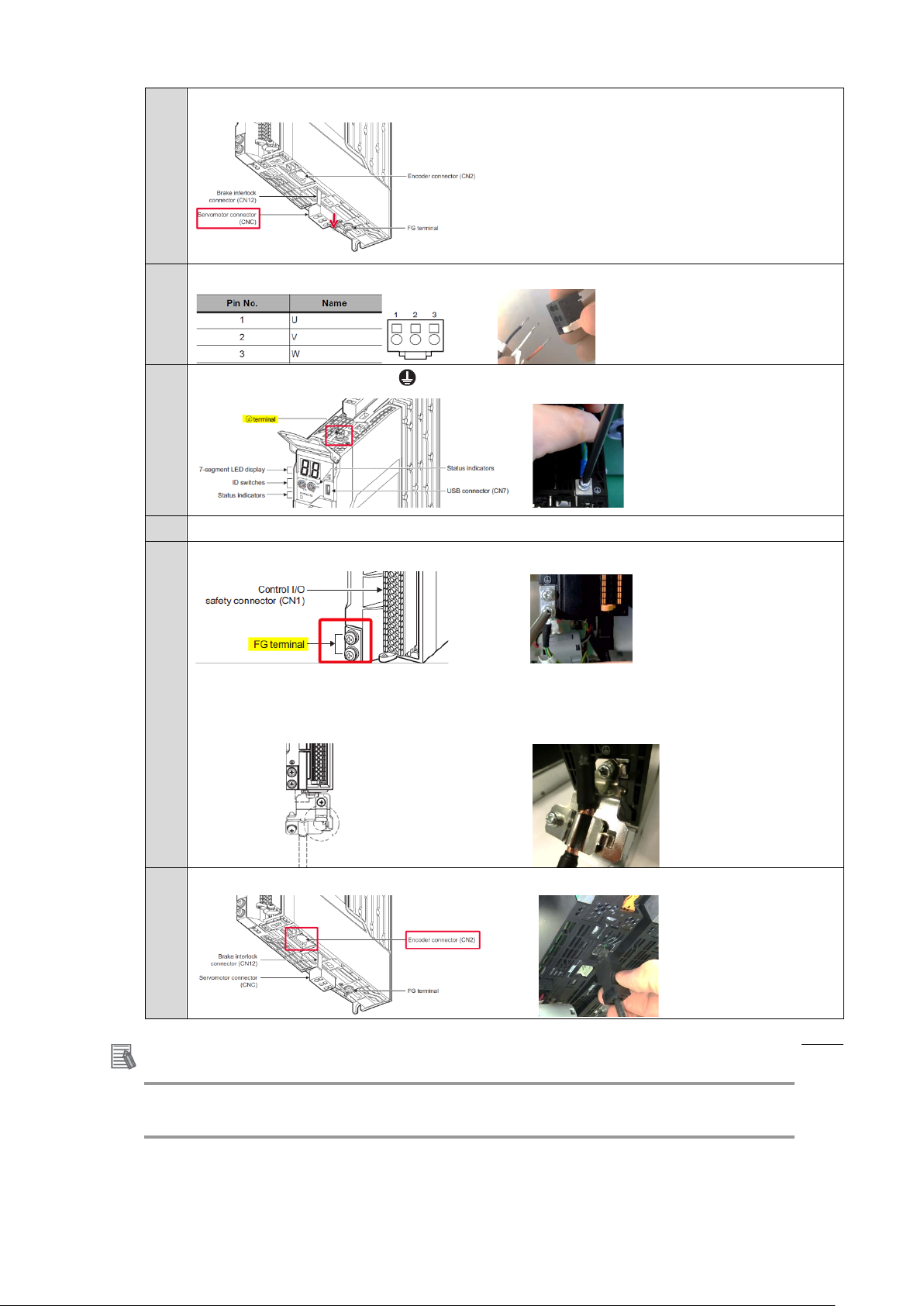
5.
Please remove the m ot or connector (CNC) from the drive:
6.
Please wire U, V, W of the motor (stripped wires)
7.
Please screw the PE wire of the main power to the drive.
8.
Please plug back above con nectors to the drive. (Po wer and Motor)
9.
Please fixe the FG wire from the motor cable to the drive
Or
In case of using the shiel d cl am p, please attach the cable to t he clamp in order to
connect the shi e l ded section.
10.
Please plug the encoder cable to the dri ve (CN2)
Additional Inf or mation
For further details about wiring method, plea se refer to 1S-series AC Servomotors and Servo Drives
User’s Manual (with Built-in EtherCAT Communications) (Cat. No. I586)
20
Page 21

■ I/0, Safety Wiring
Servo Drive
1.
By default, STO function is inhibited and bypassed with jumpers
2. In case of using STO by hardwire, Please make the proper wiring between the safety
controller and the drive
21
Page 22
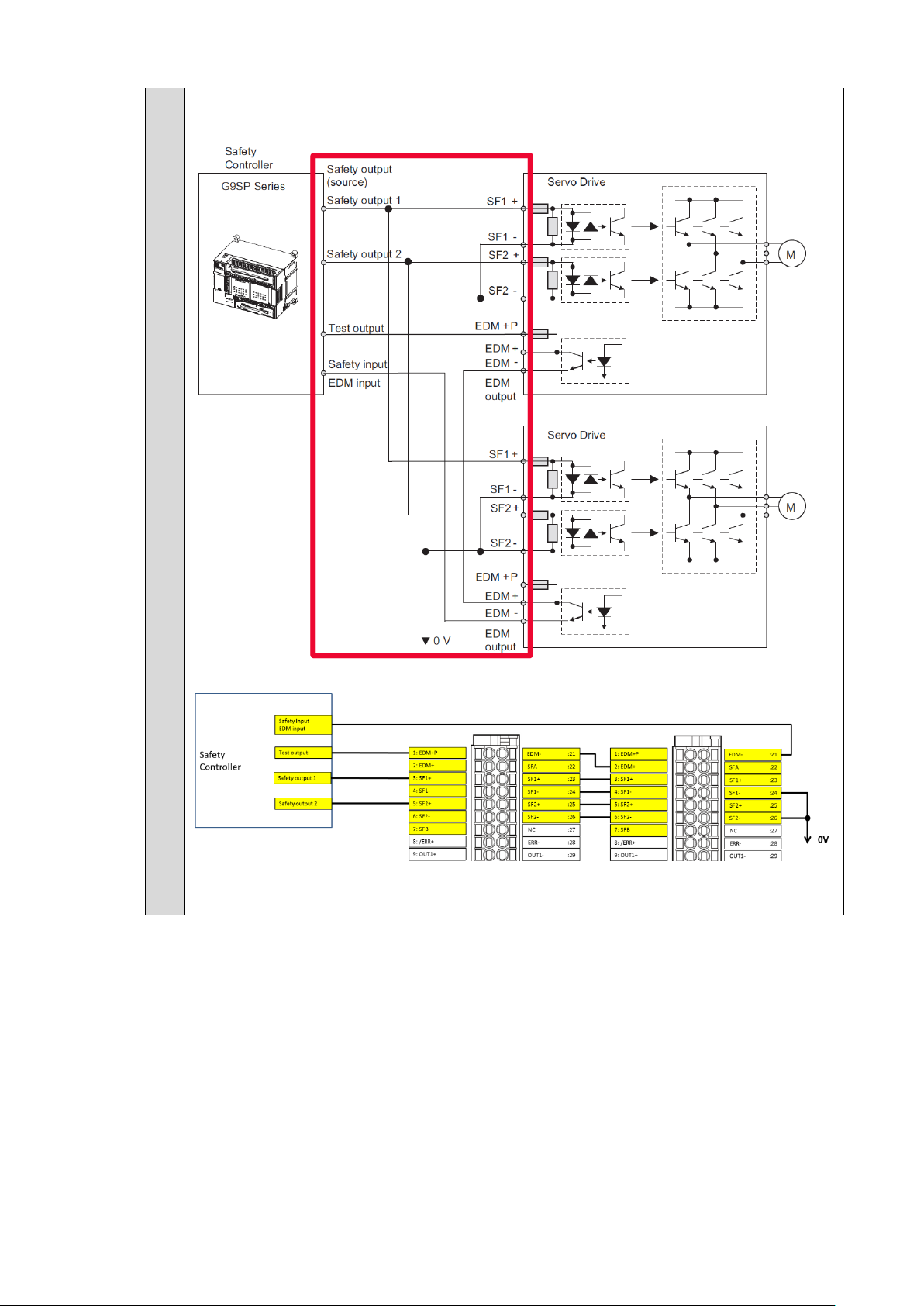
3. In case of using STO by hardwire for multiple servo drives, Please make the proper
Servo Drive 1
Servo Drive 2
wiring between the safety controller and drives.
Note: When G9SP-series safety controller is used, you can connect up to four 1S-series Servo Drives
22
Page 23

4. When general I/Os are required, please make the proper wiring.
Here is an example of latch input 1:
Servo Drive connector v ie w:
Additional Inf or mation
For further details about wiring method, plea se refer to 1S-series AC Servomotors and Servo Drives
User’s Manual (with Built-in EtherCAT Communications) (Cat. No. I586)
23
Page 24

3.2. System configuration with NJ and NX safety controller
■ Ethercat node address config uration
1.
Please configure the Ethercat node address of the drive to 1.
Note: You can configure the node address depending on your app li cat ion
2.
In case of using NX safety, please configure the no de address of the NX coupler to
2.
Note: You can configure the node address depending on your app li cat ion
3.
Please connect EtherCAT cables to devices
CN10 Ethercat IN: Ethercat cable from NJ EtherCAT Master
CN11 Ethercat OUT: Ethercat cable to NX coupler unit
24
Additional Inf or mation
For further details about s afety controller, please refer to the NX-series saf et y control
units user manual Z930
Page 25

3.3 Sysmac Studio project creation
■ New project
1.
Create new project
Select NJ501-1500 from the list.
2.
3.
Import the sizing file
Please select your sizing tool results
Note 1: P lease refer to the “motor sizing tool startup guide” for learning how to create
the sizing result (I820-E1-01).
Note 2: If you do not use the sizing file import please refer to the annex “Add drive and
axis OFFLINE”
Device was imported successfully
4.
25
Ethercat configuration was updated
Page 26

5.
6.
If you do not use NX Safety, please jump to step 10
7.
Drive parameters were u pdated
Axis setting were create d and updated
Add a terminal coupl er in EtherCAT editor
Double click on Ethercat
Drag and drop the terminal coupler
26
Page 27
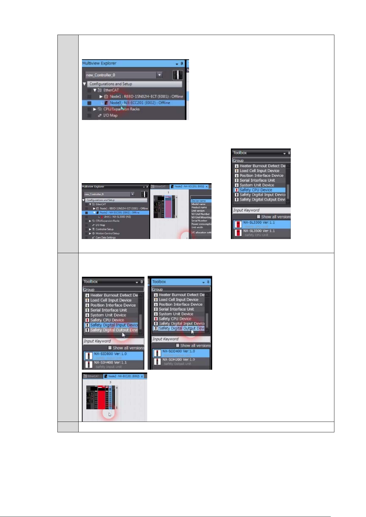
8.
Add NX Safety unit
Double click on NX Coupl er
Drag and drop NX safety cont r oller
9.
Add NX safety I/O unit s
Drag and drop Safety I/ O
10
27
Please turn on the power supply of all devices.
Page 28

11.
Connect to NJ
Please setup the method of connection
Enter the IP address and test the connection
Push connect button
12.
Send Program to NJ
Push synchronize button
Uncheck the below box in order to send driv e paramet ers and push tr ansfer to control ler
28
Page 29

3.4 Motor, ABS Encoder and I/O Setup
■ Quick setup wizard
1.
2.
Please right click to the dri ve and select “setup and tuning”
Select quick setup
3.
This setting is related with Encoder usage and I/O pre-configuration
When using I/O features of the drive in the motion control (MC) function module of
Sysmac Controller, recommended settings should be used. (Related inputs: IN2: POT,
IN3: NOT, IN4: DEC, IN7: EXT1, IN8: EXT2, Absolute encoder usage: “Use as absol ut e
encoder but ignore multi-rotat ion c ounter overflow”).
4.
Absolute encoder usag e
1S motor has an absolute encoder for all models. But it can be used as incremental if
needed. When using S ysmac Control ler, it is recom mended to k eep the def ault va lue. (as
described in previous step 3)
29
Page 30
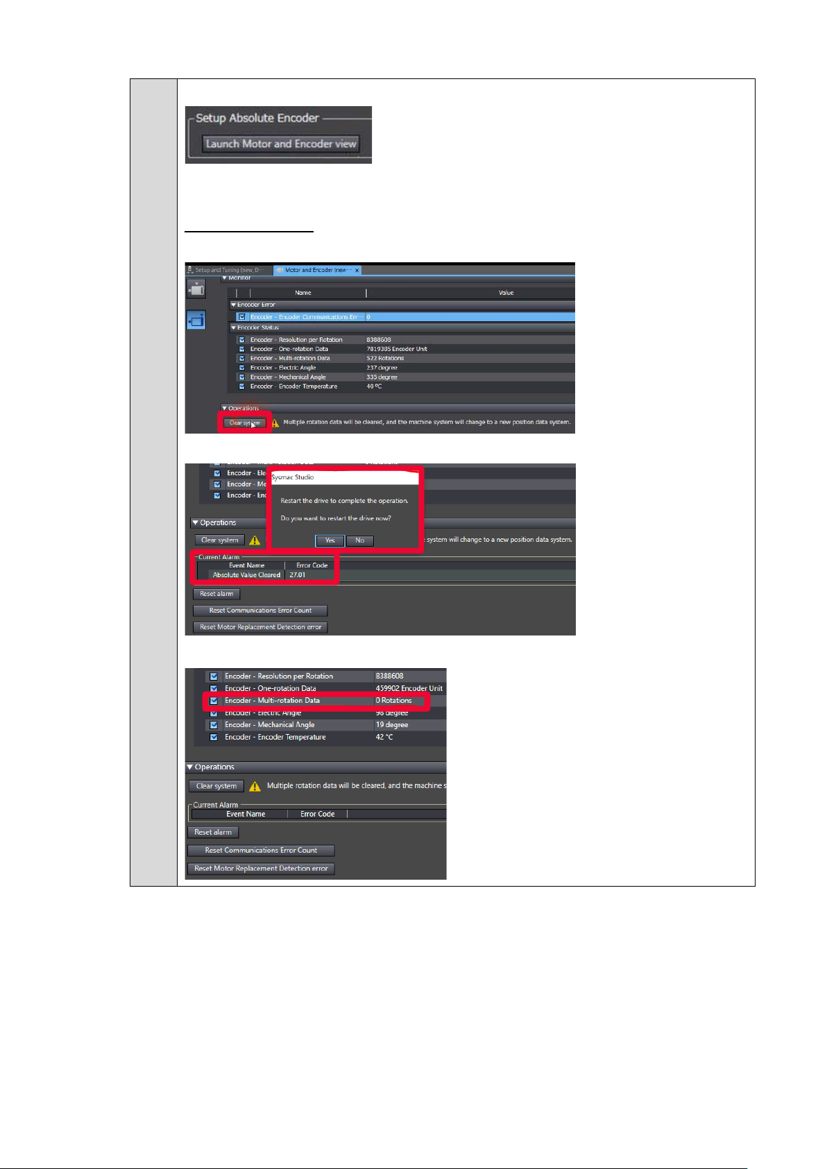
5.
Setup of the abs ol ute encoder
This function can be used for resetting the multi turn data or when replacing a motor in
actual machine.
Reset multi-turn data:
Please push “clear system”
This setting required the drive to be restarted; Sysmac Studio can do it by pressing yes.
Encoder multi rotation data has been cleared
30
Page 31

6.
7.
Adjust the motor direction and transfer to the drive
Validate the motor operation
Apply the test run configurat ion, act ivate the Servo ON and in itiate the movement
Note: In case of Error 87.00 ESTP input, please check your wiring connection or disable the
error stop input (IN1) as explained in the next step.
Click next
31
Page 32

8.
put settings, transfer to the drive and validate with test
Adjust Input settings, transfer to the drive and validate with test run
By default, ESTOP Input is activated, please deactivated if necessary ( as foll owing).
When ESTP is activ at ed, Er r or 87. 00 i s present on the drive.
9.
10.
If necessary, Adjust Out
run
Please click finish
32
Page 33
3.5. Easy tuning for gain adjustment
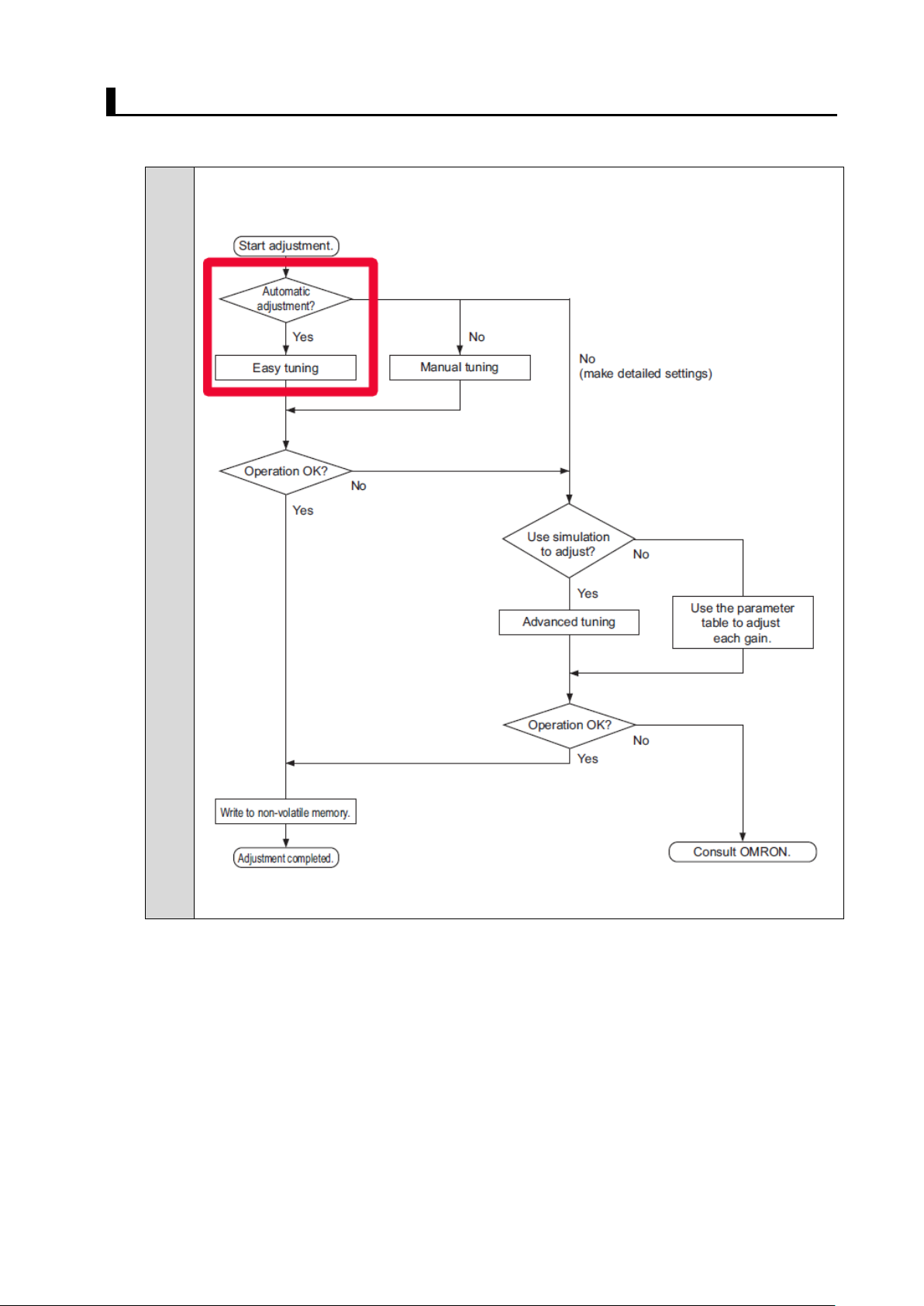
■ Easy tuning
Use the following pr ocedure to perform adj ustment. At first, it is recom mended to perform
easy tuning
33
Page 34

1.
Please right click to the dri ve and select “setup and tuning”
2.
3.
Please select Easy tuning
Please select simple mode and click next
4.
Please adjust the motion profile
34
Page 35

5.
setting of settling time, gain will be increased gradually
until achieving the specified settling time. The positioning window, specify the
position deviation to determine that the positioning is completed. If it detects a
Please adjust criteria and click next
• If you choose the manual
vibration above the vibration detection level during tuning, an adjustment failure will
occur.
• If you select the best effort mode, gain will be increased gradually until the system
does not exceed the vibra t ion detection level.
6.
Please click start, be caref ul the motor will move
Criteria achieved
Click next
35
Page 36

7.
Please click the record button, the motor will move and data will be traced and
auto scaled
Click next
8.
Confirm new gain parameters and save to EEPROM
Click Finish
36
Page 37

3.6. FSoE STO activation
If you do not use NX S afety and STO via FSoE, please ignore this par t ( 3. 6)
■ Manipulation t o activate FSoE STO
1.
Please double click on E t her cat
2.
3.
4.
Please select the drive and Edit PDO map settings of the drive
Select safety input and output (273th)
It is necessary for setting the inform at ion in the safety telegram.
Select the new safety CPU
5.
37
Please confirm the FSo E slave addresses
Safety signals from the se r vo are shown as Safety I/O
Page 38
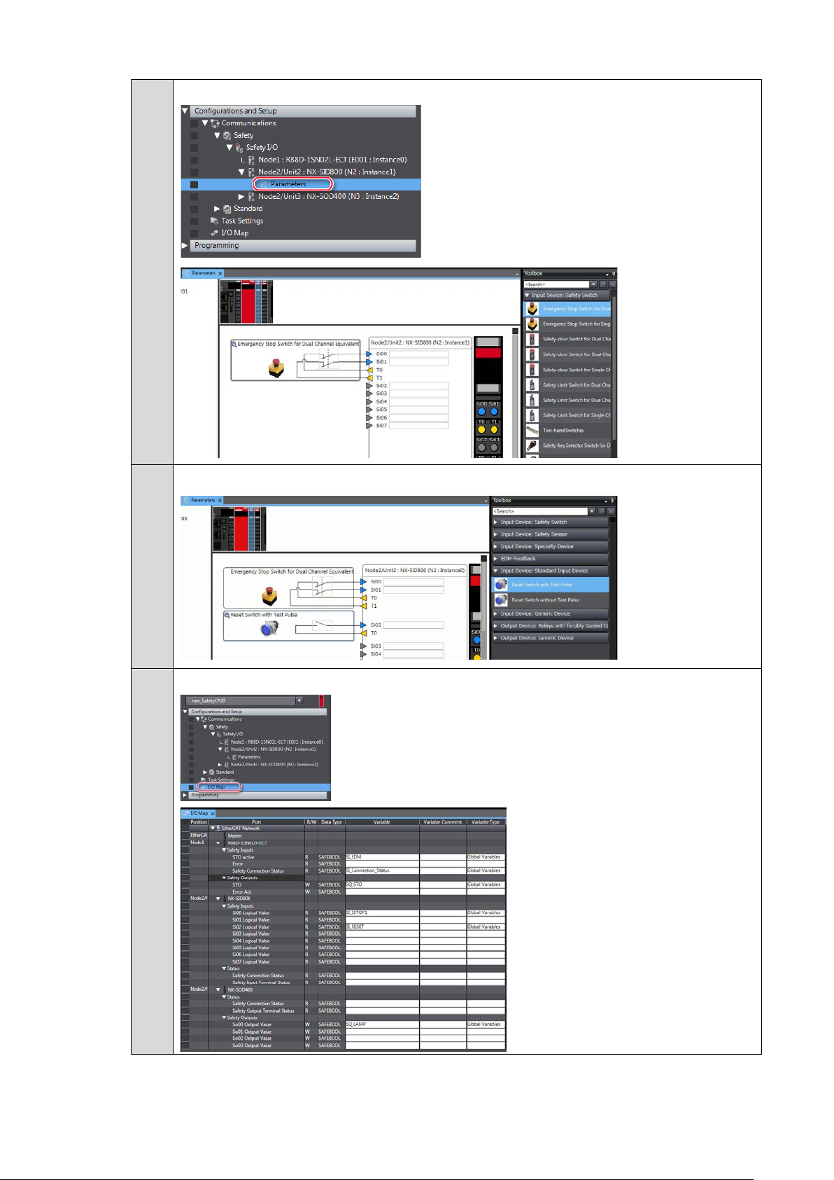
6.
Add the Emerge nc y stop button
7.
Add the Reset button
8.
Edit I/O Map variables
38
Page 39

9.
Create safety program
10.
Transfer to the controller
Please select the controll er area
Connect to the controller
Synchronize with the controller
Transfer t o t he c ont r ol ler
39
Page 40
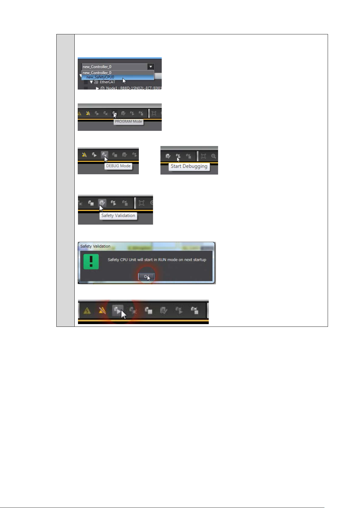
11.
Download the saf et y application
Please select the new saf et y CPU
Switch to program mode
Activate and run the debug mode
then
Click on safety validation
The safety application is now ready to run
Please click on run
40
Page 41

12.
STO is released when Emergency stop button was released and RESET button
The FSoE communication is now established
FS LED is green and fixed ON.
STO is activated when Emergency stop button is p us hed
activated.
41
Page 42
ANNEX
Add a drive and axis OFFLINE
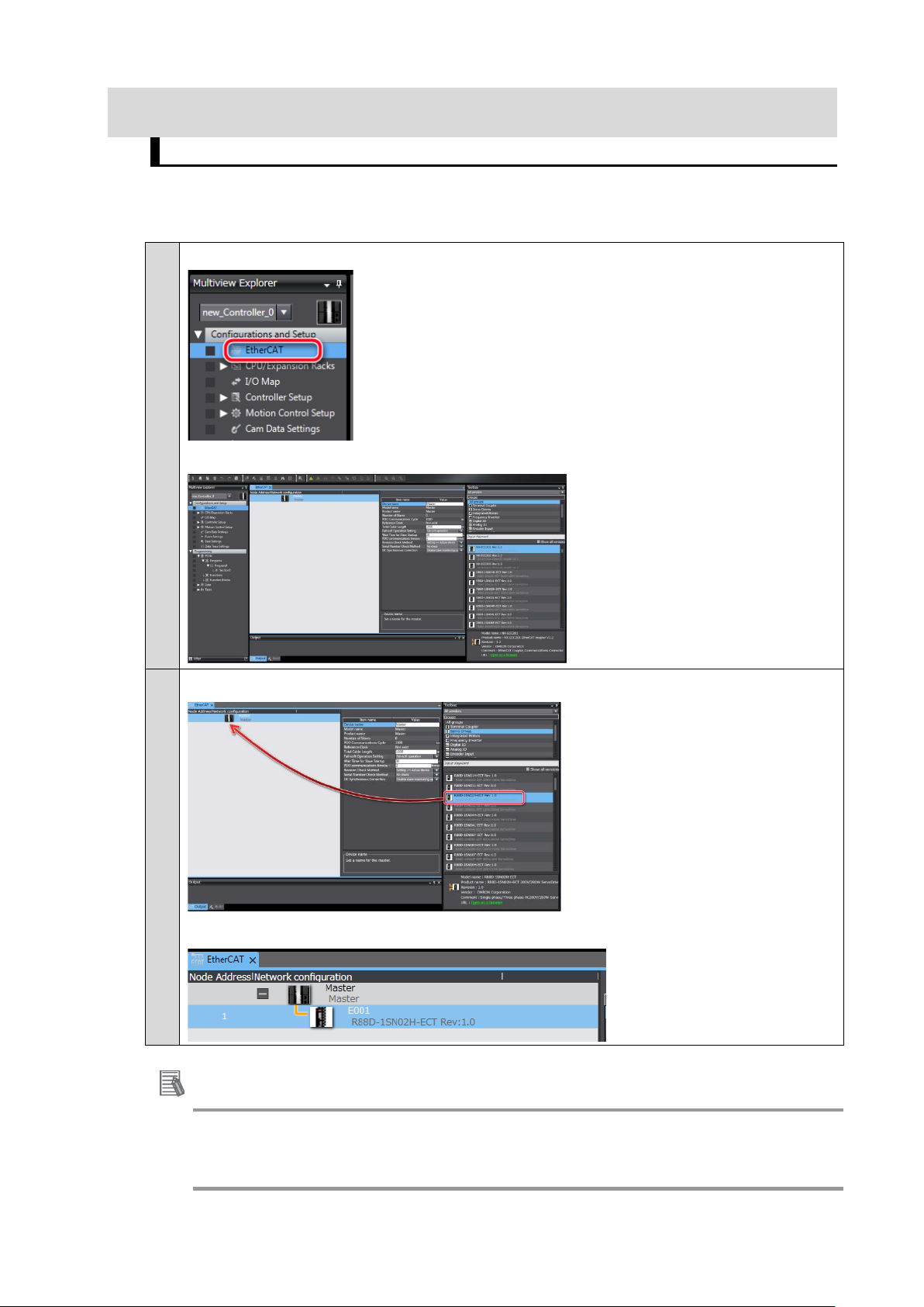
■ Creating the EtherCAT Network Configuration
1.
Double-click Et herCAT under Configurati ons and Setups in the Multiview Explorer.
The EtherCAT Tab Page is displa yed in the Edit Pane.
Drag the Drive from the Toolbox to the master on the EtherCAT Tab Page
2.
The Servo Drive is added under the master with a node address of 1.
Additional Inf or mation
If the physical EtherCAT network configuration is already connected, you can automatically create
the virtual network configuration in the Sysmac Studio based on the physical network configuration.
Refer to the Sysmac Studio Version 1 Operation Manual (Cat. No. W504) for specific procedures.
42
Page 43

■ Setting the axis
This section describes how to add the axis that is used to control the Servo Drive, assign it to the Servo
Drive, and set the axis parameters.
1.
Right-click MC_Axis000 (axis 0) in the Multiview Explorer and select Edit from the
menu.
Axis 0 is added to the Multiview Explorer. The axis is added as MC_Axis000.
2.
Right-click MC_Axis000 (axis 0) in the Multiview Explorer and select Edit from the
menu.
The Axis Bas ic S etting s are disp layed o n t he Axis Parameter Settings Tab Page in the Edit
Pane.
43
Page 44

3.
Select Servo axis in the Axis type Box.
4.
Select the Servo Driv e to use in th e Input device Box
This will assign node 1 and the dr ive to the input device for axis 0.
5.
Set the parameters on the Axis Parameter Settings Tab Page
The following figure shows the axis parameters for the unit conversion settings.
Unit of Display : degr ee
Command Pulse Count Per Motor rotation: 8388608 (23 bit)
Work travel distan ce per motor rotation: 360°
44
Page 45
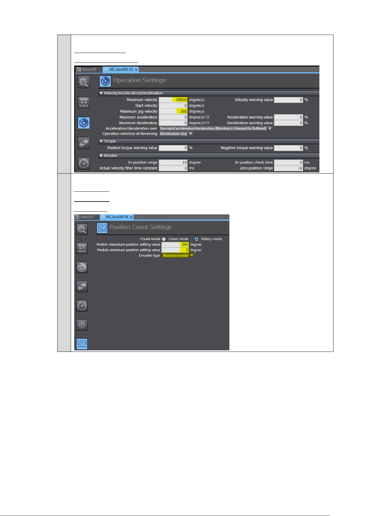
6.
Operation settings
Maximum Velocity: 18 000 degree/s
Maximum Jog V eloc ity : 360 degr ee/s
7.
Position count settings
Count mode: Rotary mode
Modulo max: 360
Modulo min: 0
45
Page 46

Test run and data trace
1.
Please right click to the dri ve and select “test run”
2.
Please click “step” tab, adj ust motion profile and apply
3.
Activate the servo ON
4.
Please right click to the “data t r ace settings” and add a new trace
5.
Chose cyclic mode
6.
Adjust the sampl i ng interval
46
Page 47

7.
Adjust the tri gge r condition
8.
Push record button
Sysmac Studio is now wait ing for t he trigger
9.
Place the T est run and Data trace windo ws side-by-side with docking window feature
Push start in test run, data t r aces will appear cyclically
47
Page 48
Manual tuning
■ Manual tuning guide
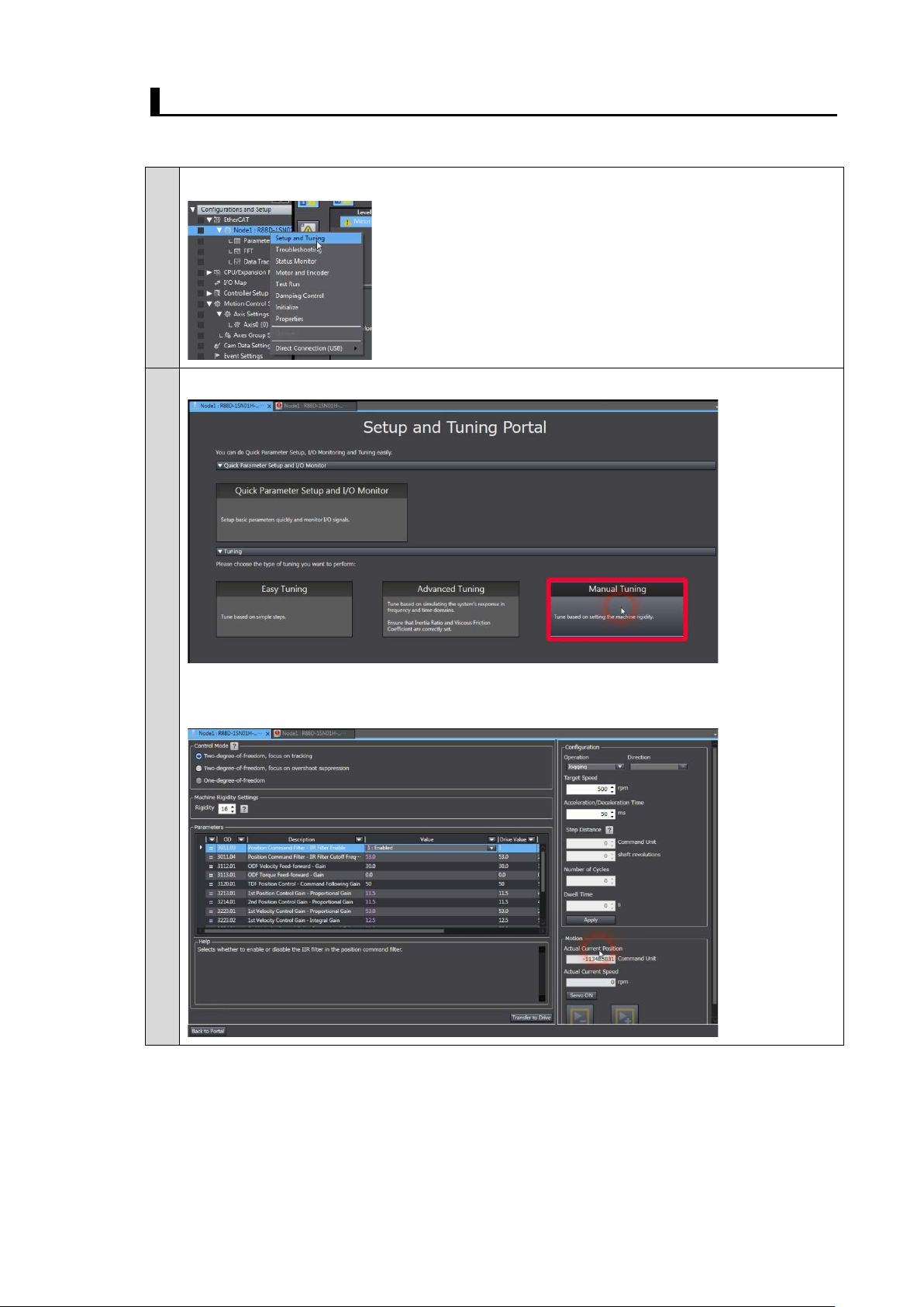
1.
Please right click to the dri ve and select “setup and tuning”
2.
Please select Manual Tuning
Manual tuning window is displayed
It includes rigidity settings, gain parameters a nd dr ive test run
48
Page 49

3.
In order to check t he behavior of the motor,
Please right click to the “data t r ace settings” and add a new trace
4.
Chose cyclic mode
5.
Adjust the sampl i ng interval
6.
Adjust the tri gge r condition
7.
Disable parameters reading
Push record button
Sysmac Studio is now wait ing for t he trigger
8.
Place the Test run and Manual tuning windows sid e-by-side with docking window
feature
49
Page 50

9.
Configure the motion profile a nd click Apply
10.
Activate the Servo ON and Push Start
Be careful, the motor wil l move in the forward and reverse direction
11.
The data trace is now triggere d and result displayed
Each time the motor will move, t r aces w i ll a ppear cyclically.
50
Page 51

12.
It is possible to increase gain values by changing the rigidity settings
Push transfer to send the gain par ameters to the drive.
13.
Please repeat step 10,11 and 12 until achieving the desired performance
If vibrations appear, please reduce the rigidity settings.
If required, It is possible to increase respon siv eness by applying notch filters in advanced
tuning mode and adjustin g gai ns . Pl ease refer to Annex “Advanced tuning
”.
51
Page 52
Advanced tuning
■ Advanced tuning guide
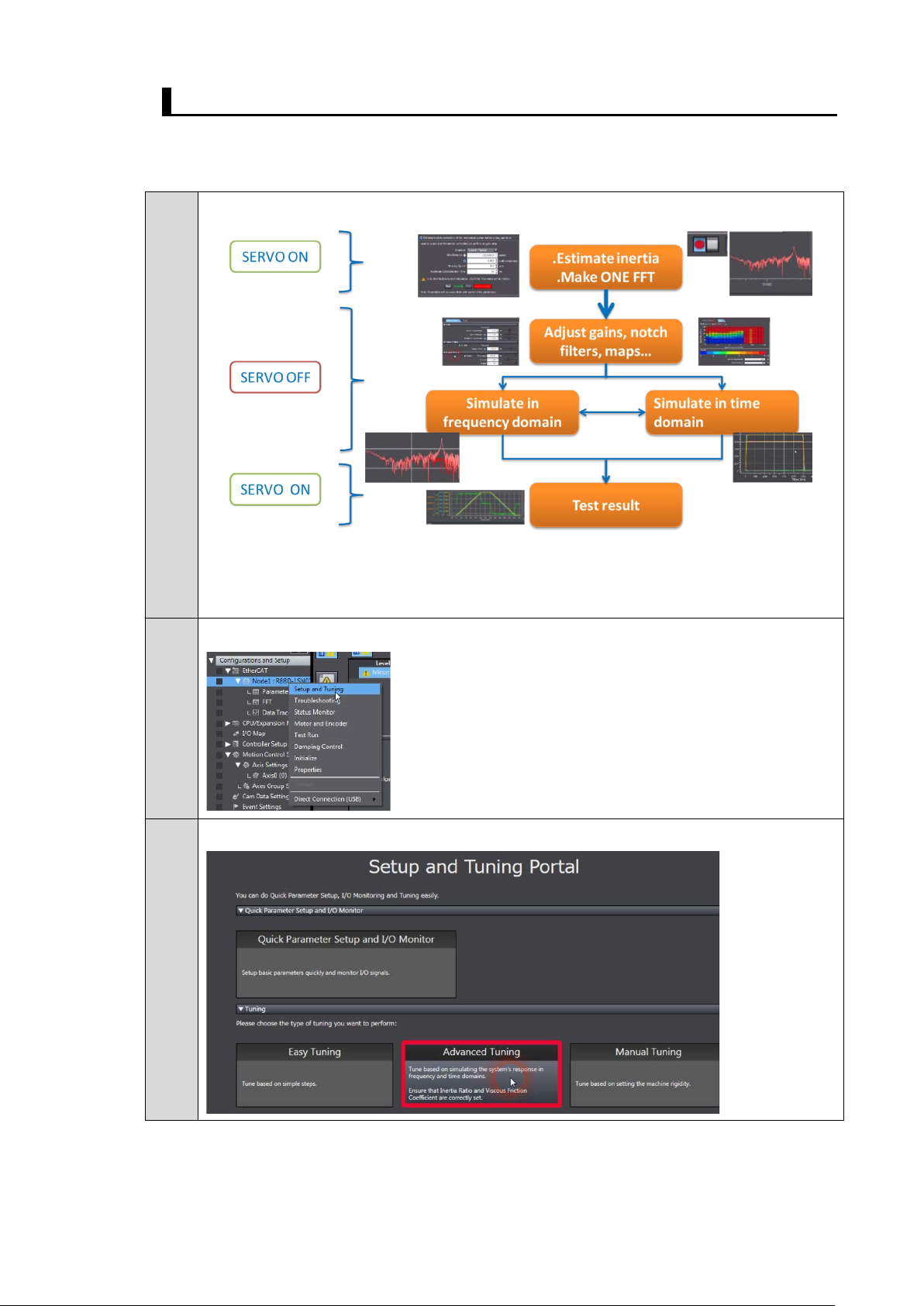
Overview
1.
2.
Below example explain the way to tune a 1S servo drive and motor with advanced
tuning. This method of tuning d ecr ease dramatically the number of tests and trial with
actual machine.
Please right click to the dri ve and select “setup and tuning”
Please select Advanced T uning
52
Page 53

3.
Configuration (Wizard Step 1)
Please select your contr ol mode
Please estimate the loa d characteristics by push ing start (the motor will move)
If easy tuning has been performed already, please select “use present setting”
Load characteristics hav e been updated
4.
Click Next
Frequency response simulation (Wizard Step 2)
Please start the trace (FFT measurement will be performed, the motor will move slightly)
FFT measureme nt and simulated values are display ed ( G ai n and Phase)
53
Page 54

5.
Adjust gain and simulate
Please select Maps feature:
Adjust the gain t o a proper value and push “refresh sim ul at i on ”
FROM
Pink curve is the measured value
Red curve is the simulated value
TO
54
Page 55

6.
notch filter to remove this resonance frequency at 2411 Hz:
Adjust notch filters and simulate
After increasing gains, the gain simulation shows a peak near 0dB. This peak shows a
resonance frequency:
Activate the cursor to measure the frequency
Activate the 1st
55
Page 56

7.
Increase gain with Maps and simulate
After activating the notch f ilter, gain can be increased and perfor mance i mprov ed
8.
FROM
Before notch
Time response simul at ion (Wizard step 3)
In time response simulati on, the motion profile can be simulated.
Please push “Simulate Mo t i on Profile”
TO
56
The chart is updated and show s :
- The spe ed command, speed detect ion simulati on and following er ror simulatio n.
If necessary, please adjust gains:
Page 57
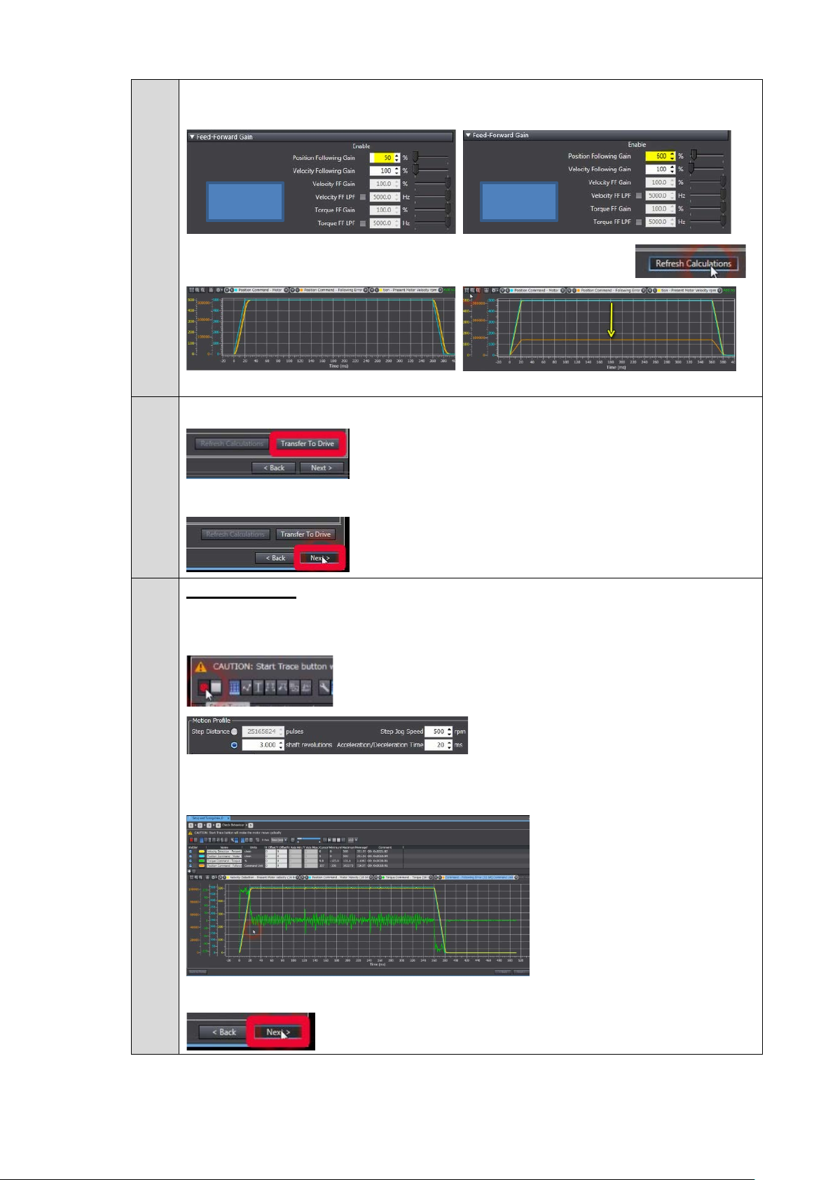
9.
(the motor will move following the previous configuration in Wizard
If your application required a small tracking error, here is an example of position
following gain adjustment:
FROM TO
Following error has been reduced.
When satisfied with the si mul at i on result, please transfer parameters to the drive
Click Next
10.
Check behavior (Wi zar d step 4)
Push start trace
step 3)
(motion profile in Wizard step 3)
The chart is updated and show s :
- The sp eed command, speed detection, following error and tor que.
If satisfied, please click next
57
Page 58

11.
Results (Wizard step 5)
Save to EEPROM
Finish
58
Page 59

2016
Note:DonotusethisdocumenttooperatetheUnit.
I823-E1-01
0616 (0616)
 Loading...