

Page 1

Cat. No. I203-E2-02
R88A-MCW151-E
R88A-MCW151-DRT-E
Motion Control Option
Board
OPERATION MANUAL
Page 2

MCW151 Series
Motion Control Option Board
Models: R88A-MCW151-E
R88A-MCW151-DRT-E
Operation Manual
Produced March 2003
Page 3

Page 4

Notice:
OMRON products are manufactured for use according to proper procedu res by a qualified operator
and only for the purposes described in this manual.
The following conventions are used to indicate and classify precautions in this manual. Always heed
the information provided with them. Failure to heed precautions can result in injur y to p eople or damage to property.
!DANGER
!WARNING
!Caution
Indicates an imminently hazardous situation which, if not avoided, will result in death or
serious injury.
Indicates a potentially hazardous situation which, if not avoided, could result in death or
serious injury.
Indicates a potentially hazardous situation which, if not avoided, may result in minor or
moderate injury, or property damage.
OMRON Product References
All OMRON products are capitalized in this manual. The word “Unit” is also capitalized when it refers to
an OMRON product, regardless of whether or not it appears in the proper name of the product.
The abbreviation “Ch”, which appears in some displays and on some OMRON products, often means
“word” and is abbreviated “Wd” in documentation in this sense.
The abbreviation “PC” means Programmable Controller and is not used a s an abbreviation for anything else.
Visual Aids
The following headings appear in the left column of the manual to help you locate different types of
information.
Note In dicates information of par ticular interest for efficient and convenient opera-
tion of the product.
1,2,3... Indicates lists of one sort or another, such as procedures, checklists, etc.
Trademarks and Copyrights
DeviceNet is a registered trademark of the Open DeviceNet Vendor Association, Inc.
OMRON, 2003
All rights reserved. No part of this publication may be reproduced, stored in a retrieval system, or transmitted, in
any form, or by any means, mechanical, electronic, photocopying, recording, or otherwise, without the prior
written permission of OMRON.
No patent liability is assumed with respect to the use of the information contained herein. Moreover, because
OMRON is constantly striving to improve its high-quality products, the information contained in this manual is
subject to change without notice. Every precaution has been taken in the preparation of this manual. Nevertheless, OMRON assumes no responsibility for errors or omissions. Neither is any liability assumed for damages
resulting from the use of the information conta ined in this publication.
v
Page 5

vi
Page 6

About this Manual:
This manual descri bes the installation and operation o f the R88A-MCW151-E an d R88A-MCW151DRT-E Motion Control Option Boards (MC Units) and includes the sections described below.
Please read this manual and the related manuals listed in the following table carefully and be sure you
understand the information provided before attempting to install or operate the MC Unit. Be sure to
read the precautions provided in the following section.
Name Cat. No. Contents
MCW151 Series
R88A-MCW151-E
R88A-MCW151-DRT-E
Operation Manual
OMNUC W-series
R88M-W
R88D-W
User’s manual
DeviceNet Operation Manual W267 Describes the conf iguration and construct ion of a DeviceNet net-
DeviceNet Conf igurator Operation Manual
❏ (AC Servomotors)
❏ (AC Servo Drivers)
I203 Describes the instal lation and operation of the R88A-MCW151-E
and MCW151-DRT-E Motion Control Units.
(This manua l)
I531 Describes the inst al lation a nd oper ati on of t he W -seri es Servo Dri ver
and Servomotor.
work, including installation procedures and specifications for cables,
connectors, and other connection devices, as well as information on
the communic ations power supply.
W328 Describes the operation of the DeviceNet Configurator to allocate
remote I/O areas according to application needs, as well as procedures to set up a DeviceNet network with more than one master.
Precautions provides general precautions for using the MC Unit and related devices.
Section 1
describes the features and system configuration of the R88A-MCW151-E and R88A-
MCW151-DRT-E Motion Control Units and concepts related to their operation.
Section 2
Section 3
describes the MC Unit components and provides the information for installing the MC Unit.
describes the different Motion Control features of the MCW151. Also the functiona lity of the
Servo Driver related commands are explained.
Section 4
describes the com munication componen ts of the MCW 151-E and MCW151-DRT-E. The
functionality of the serial communication protocols and the DeviceNet interface are explained.
Section 5
provides an overview of the fundamentals of multitasking BASIC progr a ms and the methods
by which programs are managed in the MC Unit.
Section 6
describes all commands, functions and parameters required for programing the motion con-
trol application using the MC Unit.
Section 7
describes the operation of the Motion Perfect programming software package. Motion Per-
fect provides the user a tool to program, monitor and debug motion based applications for the MC Unit.
Section 8
describes error processing and troubleshooting procedures needed to keep the system
operating properly.
Section 9
explains the maintenance and inspec tion procedures that must b e followed to keep the M C
Unit operating in optimum condition. It also includes proper procedures when replacing an MC Unit.
The Appendices provide the required p arameter settings for the Ser vo Driver, the DeviceNet protocol
specification and some general programming examples.
!WARNING
Failure to read and understand the information pro vided in this manual may result in personal injury or death, damage to t he product, or product failure. Pleas e read each section
in its entirety and be sure you unders tand the information provided in the section and
related sections before attempting any of the procedures or operations given.
vii
Page 7

Page 8

TABLE OF CONTENTS
PRECAUTIONS . . . . . . . . . . . . . . . . . . . . . . . . . . . . . . . . xi
1 Intended Audience . . . . . . . . . . . . . . . . . . . . . . . . . . . . . . . . . . . . . . . . . . . . . . . . . xii
2 General Precautions . . . . . . . . . . . . . . . . . . . . . . . . . . . . . . . . . . . . . . . . . . . . . . . . xii
3 General Warnings and Safety Precautions . . . . . . . . . . . . . . . . . . . . . . . . . . . . . . . xii
4 Storage and Transportation Precautions . . . . . . . . . . . . . . . . . . . . . . . . . . . . . . . . . xiv
5 Installation and Wiring Precautions . . . . . . . . . . . . . . . . . . . . . . . . . . . . . . . . . . . . xiv
6 Operation and Adjustment Precautions. . . . . . . . . . . . . . . . . . . . . . . . . . . . . . . . . . xv
7 Maintenance and Inspection Precautions . . . . . . . . . . . . . . . . . . . . . . . . . . . . . . . . xv
8 Conformance to EC Directives . . . . . . . . . . . . . . . . . . . . . . . . . . . . . . . . . . . . . . . . xv
SECTION 1
Features and System Configuration . . . . . . . . . . . . . . . . 1
1-1 Features. . . . . . . . . . . . . . . . . . . . . . . . . . . . . . . . . . . . . . . . . . . . . . . . . . . . . . . . . . 2
1-2 System Configuration . . . . . . . . . . . . . . . . . . . . . . . . . . . . . . . . . . . . . . . . . . . . . . . 5
1-3 Motion Control Concepts . . . . . . . . . . . . . . . . . . . . . . . . . . . . . . . . . . . . . . . . . . . . 7
1-4 Control System Configuration . . . . . . . . . . . . . . . . . . . . . . . . . . . . . . . . . . . . . . . . 14
1-5 Specifications . . . . . . . . . . . . . . . . . . . . . . . . . . . . . . . . . . . . . . . . . . . . . . . . . . . . . 19
1-6 Comparison between Firmware Versions . . . . . . . . . . . . . . . . . . . . . . . . . . . . . . . . 21
SECTION 2
Installation. . . . . . . . . . . . . . . . . . . . . . . . . . . . . . . . . . . . . 23
2-1 Components and Unit Settings . . . . . . . . . . . . . . . . . . . . . . . . . . . . . . . . . . . . . . . . 24
2-2 Installation. . . . . . . . . . . . . . . . . . . . . . . . . . . . . . . . . . . . . . . . . . . . . . . . . . . . . . . . 28
2-3 Wiring . . . . . . . . . . . . . . . . . . . . . . . . . . . . . . . . . . . . . . . . . . . . . . . . . . . . . . . . . . . 30
2-4 Servo System Precautions . . . . . . . . . . . . . . . . . . . . . . . . . . . . . . . . . . . . . . . . . . . . 39
2-5 Wiring Precautions . . . . . . . . . . . . . . . . . . . . . . . . . . . . . . . . . . . . . . . . . . . . . . . . . 40
SECTION 3
Motion Control Functions . . . . . . . . . . . . . . . . . . . . . . . . 43
3-1 Overview . . . . . . . . . . . . . . . . . . . . . . . . . . . . . . . . . . . . . . . . . . . . . . . . . . . . . . . . . 44
3-2 System Set-up . . . . . . . . . . . . . . . . . . . . . . . . . . . . . . . . . . . . . . . . . . . . . . . . . . . . . 46
3-3 System Functions . . . . . . . . . . . . . . . . . . . . . . . . . . . . . . . . . . . . . . . . . . . . . . . . . . 47
SECTION 4
Communication Interfaces. . . . . . . . . . . . . . . . . . . . . . . . 59
4-1 Serial Communications. . . . . . . . . . . . . . . . . . . . . . . . . . . . . . . . . . . . . . . . . . . . . . 60
4-2 DeviceNe t (MCW151-DRT -E only) . . . . . . . . . . . . . . . . . . . . . . . . . . . . . . . . . . . . 68
ix
Page 9

TABLE OF CONTENTS
SECTION 5
Multitasking BASIC Programming . . . . . . . . . . . . . . . . . 85
5-1 Overview . . . . . . . . . . . . . . . . . . . . . . . . . . . . . . . . . . . . . . . . . . . . . . . . . . . . . . . . 86
5-2 BASIC Programming. . . . . . . . . . . . . . . . . . . . . . . . . . . . . . . . . . . . . . . . . . . . . . . 86
5-3 Motion Execution . . . . . . . . . . . . . . . . . . . . . . . . . . . . . . . . . . . . . . . . . . . . . . . . . 89
5-4 Command Line Interface . . . . . . . . . . . . . . . . . . . . . . . . . . . . . . . . . . . . . . . . . . . . 90
5-5 BASIC Programs . . . . . . . . . . . . . . . . . . . . . . . . . . . . . . . . . . . . . . . . . . . . . . . . . . 90
5-6 Task Operation Sequence . . . . . . . . . . . . . . . . . . . . . . . . . . . . . . . . . . . . . . . . . . . 93
5-7 Error Processing. . . . . . . . . . . . . . . . . . . . . . . . . . . . . . . . . . . . . . . . . . . . . . . . . . . 94
SECTION 6
BASIC Motion Control Programm ing Langua ge . . . . . 97
6-1 Overview . . . . . . . . . . . . . . . . . . . . . . . . . . . . . . . . . . . . . . . . . . . . . . . . . . . . . . . . 102
6-2 Command Reference List . . . . . . . . . . . . . . . . . . . . . . . . . . . . . . . . . . . . . . . . . . . 103
6-3 Command, function and parameter description. . . . . . . . . . . . . . . . . . . . . . . . . . . 111
SECTION 7
Motion Perfect Software Package . . . . . . . . . . . . . . . . . . 197
7-1 Features and Requirements . . . . . . . . . . . . . . . . . . . . . . . . . . . . . . . . . . . . . . . . . . 198
7-2 Connecting to the MC Unit . . . . . . . . . . . . . . . . . . . . . . . . . . . . . . . . . . . . . . . . . . 198
7-3 Motion Perfect Projects . . . . . . . . . . . . . . . . . . . . . . . . . . . . . . . . . . . . . . . . . . . . . 199
7-4 Desktop Appearance . . . . . . . . . . . . . . . . . . . . . . . . . . . . . . . . . . . . . . . . . . . . . . . 201
7-5 Motion Perfect Tools . . . . . . . . . . . . . . . . . . . . . . . . . . . . . . . . . . . . . . . . . . . . . . . 204
7-6 Suggestions and Precautions . . . . . . . . . . . . . . . . . . . . . . . . . . . . . . . . . . . . . . . . . 217
SECTION 8
Troubleshooting. . . . . . . . . . . . . . . . . . . . . . . . . . . . . . . . . 219
8-1 Error Indicators . . . . . . . . . . . . . . . . . . . . . . . . . . . . . . . . . . . . . . . . . . . . . . . . . . . 220
8-2 Error Handling . . . . . . . . . . . . . . . . . . . . . . . . . . . . . . . . . . . . . . . . . . . . . . . . . . . . 221
8-3 Problems and Countermeasures. . . . . . . . . . . . . . . . . . . . . . . . . . . . . . . . . . . . . . . 227
SECTION 9
Maintenance and Inspection. . . . . . . . . . . . . . . . . . . . . . . 233
9-1 Routine Inspections . . . . . . . . . . . . . . . . . . . . . . . . . . . . . . . . . . . . . . . . . . . . . . . . 234
9-2 Replacing a MC Unit. . . . . . . . . . . . . . . . . . . . . . . . . . . . . . . . . . . . . . . . . . . . . . . 235
Appendices
Appendix A Servo Driver Parameter List . . . . . . . . . . . . . . . . . . . . . . . . . . . . . . . . . 237
Appendix B Device Protocol (MCW151-DRT-E only). . . . . . . . . . . . . . . . . . . . . . . 239
Appendix C Programming Examples. . . . . . . . . . . . . . . . . . . . . . . . . . . . . . . . . . . . . 245
Index. . . . . . . . . . . . . . . . . . . . . . . . . . . . . . . . . . . . . . . . . . 255
Revision History . . . . . . . . . . . . . . . . . . . . . . . . . . . . . . . . 261
x
Page 10

PRECAUTIONS
This section provides general precautions for using the Motion Control Unit and related devices.
The information contained in this section is important for the safe and reliable application of the Motio n Control
Unit. You must read this section and u nderstand the information contained before attempting to set up or o perate
a Motion Control Unit and Servo Dri ver.
1 Intended Audience . . . . . . . . . . . . . . . . . . . . . . . . . . . . . . . . . . . . . . . . . . . . . xii
2 General Precautions . . . . . . . . . . . . . . . . . . . . . . . . . . . . . . . . . . . . . . . . . . . . xii
3 General Warnings and Safety Precautions . . . . . . . . . . . . . . . . . . . . . . . . . . . xii
4 Storage and Transportation Precautions . . . . . . . . . . . . . . . . . . . . . . . . . . . . . xiv
5 Installation and Wiring Precautions . . . . . . . . . . . . . . . . . . . . . . . . . . . . . . . . xiv
6 Operation and Adjustment Precautions. . . . . . . . . . . . . . . . . . . . . . . . . . . . . . xv
7 Maintenance and Inspection Precautions . . . . . . . . . . . . . . . . . . . . . . . . . . . . xv
8 Conformance to EC Directives . . . . . . . . . . . . . . . . . . . . . . . . . . . . . . . . . . . . xv
8-1 Concepts . . . . . . . . . . . . . . . . . . . . . . . . . . . . . . . . . . . . . . . . . . . . . . xvi
8-1-1 Conformance to EC Directives . . . . . . . . . . . . . . . . . . . . . . . . . . . . . xvi
xi
Page 11

Intended Audience 1
1 Intended Audience
This manual is intended for the following personnel, who must a lso have knowledge of el ectr ical systems (an electrical engineer or the equivalent).
• Personnel in charge of installing FA systems.
• Personnel in charge of designing FA systems.
• Personnel in charge of managing FA systems and facilities.
2 General Precautions
The user must operate t he product accordi ng to the perfor mance specifications described in
the operation manuals. You should assume t hat anything not des cribed in this manual is not
possible.
Before using the product under the following conditions, consult your OMRON representative,
make sure the ratings and performance characteristics of the products are good enough for
the systems, machines, or equipment, and be sure to provide the systems, machines, or
equipment with double safety mechanisms.
1. Conditions not described in the manual.
2. The application of the product to nuclear control systems, railroad systems, aviation systems, vehicles, combustion systems, medical equipment, amusement machines, or safety
equipment.
3. The application of the product to systems, machines, or equipment that may have a serious
influence on human life and property if they are used improperly.
!WARNING
It is extremely important that Mot ion Control Units and related devices be used for the
specified purpose and under the specif ied conditions, especially in applications that can
directly or indirectly affect human life. You must consult with your OMRON representative
before applying Motion Control Units an d related devices to the above mentione d applications.
3 General Warnings and Safety Precautions
Observe the following warnings when using the MC Unit and all pheripheral devices.
Consult your OMRON representative when using the product after a long period of storage.
!WARNING
!WARNING
!WARNING
!WARNING
!WARNING
Always connect the frame ground terminals of the S ervo Dr iver and the Servomotor to a
class-3 ground (to 100 Ω or less). Not connecting to a class-3 ground may result in electric shock.
The product contains dangerous high voltage inside. Tur n OF F the power and wait for at
least five minutes to allow power to discharge before handling or working with the product.
Do not touch the inside of the Servo Driver. Doing so may result in electric shock.
Do not remove the front cover, terminal covers, cables, Parameter Units, or optional
items while the power is being supplied. Doing so may result in electric shock.
Installation, operation, maintenance, or inspection must be performed by authorized per-
sonnel. Not doing so may result in electric shock or injury.
!WARNING
!WARNING
xii
Wiring or inspection must not be performed for at least five minutes after turning OFF the
power supply. Doing so may result in electric shock.
Do not damage, press, or put excessive stress or heavy objects on the cables. Doing so
may result in electric shock, stopping operation of the product, or burning.
Page 12

General Warnings and Safety Precautions 3
!WARNING
!WARNING
!WARNING
!WARNING
Do not touch the rotating par ts of the Servomotor in operation. Doing so m ay result in
injury.
Do not modify the product. Doing so may result in injury or damage to the product.
Provide safety measures in external control circuits (i.e., not in the MC Unit) to ensure
safety in the system if an abnormality occurs due to malfunction of the MC Unit, incorrect
or unintended configuration and programming of the MC Unit or external factors affecting
the operation of the MC Unit. Not providing sufficient safety measures may result in serious accidents, or property damage.
• The MC Unit ou tputs m ay remain ON or OFF due to deposits on or burning of th e out put relays, or destruction of the output transistors. As a counter-measure for such problems, external safety measures must be provided to ensure safety in the system.
• Provide an external em ergency stopping device that allows an i nstantaneous stop of
operation and power interruption. Not doing so may result in injury.
• Emergency stop circuits, interlock circuits, limit circuits, and similar safety measures
must be provided in external control circuits.
• When the 24 -VDC output (service power supply to the Unit) is overloaded or short-circuited, the voltage may drop and result in the output s being turned OFF. As a countermeasure for such problems, external safety measures must be provided to ensure
safety in the system.
It is the nature of high speed motion control and mot ion control language programming
and multi-tasking systems, that it is not always possible for the system to validate the
inputs to the functions or to validate the combination of functions.
!WARNING
!Caution
!Caution
!Caution
!Caution
It is t he responsibi li ty of the prog rammer to e n s u re that the various BASIC statements are
invoked correctly with the correct number of parameters and inputs, that the values are
correctly validated prior to the actual calling of the functions, and that the BASIC program(s) provide the desired functionality for the application. Failure to do so may result in
unexpected behaviour, loss or damage to the machinery.
When the SERVO_PERIOD parameter has been s et t o change the ser vo cycle pe riod of
the MC Unit, a power down or software reset (using DRV_RESET) must be performed for
the complete system. Not doing so may result in undefined behaviour.
Use the Servomotors and Servo Drivers in a specified combination. Using them incorrectly may result in fire or damage to the product.
Do not operate the control system in the following locations:
• Locations subject to direct sunlight.
• Locations subject to temperat ures or hum idity out side the ra nge spec ified in th e spec i-
fications.
• Locations subject to condensation due to radical temperature changes.
• Locations subject to corrosive or inflammable gases.
• Locations subject to dust (especially iron dust) or salts.
• Locations subject to vibration or shock.
• Locations subject to exposure to water, oil or chemicals.
Do not touch the Servo Driver radiator, Regeneration Resistor, or Servomotor while the
power is being supplied or soon after power is turned OFF. Doing so may result in a skin
burn due to the hot surface.
xiii
Page 13

Storage and Transportation Precau tions 4
4 Storage and Tran sportation Precautions
!Caution
!Caution
!Caution
Do not hold the product by the cables or motor shaft while transporting it. Doing so may
result in injury or malfunction.
Do not place any load exceeding the figure indicated on the product. Doing so may result
in injury or malfunction.
Use the motor eye-bolts only for transporting the M otor. Using them for transporting the
machine ry may resu lt in in j u ry or malf u nc ti o n .
5 Installation and Wiring Precautions
!Caution
!Caution
!Caution
!Caution
!Caution
!Caution
!Caution
Do not step or place a heavy object on the product. Doing so may result in injury.
Do not cover the inlet or outlet ports and prevent any foreign objects from entering the
product. Doing so may result in fire.
Be sure to install the product in the right direction. Not doing so may result in malfunction.
Provide the specified clearance between the Servo Driver and the control panel or with
other devices. Not doing so may result in fire or malfunction.
Do not apply any strong impact. Doing so may result in malfunction.
Be sure to wire correc tly and sec urely. Not doing so may result in motor r unaway, injury,
or malfunction.
Be sure that all mounting screws, term inal sc rews, and cable connector screws are tight-
ened securely. Incorrect tightening may result in malfunction.
!Caution
!Caution
!Caution
!Caution
!Caution
!Caution
!Caution
Use crimp ter minals for wiring. Do not connect b are stranded wires directly to ter minals.
Connection of bare stranded wires may result in fire.
Always use the power supply voltages specified in the manual. An incorrect voltage may
result in malfunction or burning.
Take appropr iate m eas ures t o en su re that the spec ified power with the rated voltage a nd
frequency is supplied. Be par ticularly careful in places wh ere the power suppl y is unstable. An incorrect power supply may result in malfunction.
Install external breakers and take other safety measures against short-circuiting in external wiring. Insufficient safety measures against short-circuiting may result in burning.
Take appropriate and sufficient countermeasures when installing systems in the following
locations. Not doing so may result in damage to the product.
• Locations subject to static electricity or other sources of noise.
• Locations subject to strong electromagnetic fields.
• Locations subject to possible exposure to radiation.
• Locations near power supply lines.
Do not reverse the polarity of the battery when connect ing it. Reversing the polarity may
damage the battery or cause it to explode.
Before touching a Unit, be sure to first touch a grounded metallic objec t in order to discharge any static build-up. Not doing so may result in malfunction or damage.
xiv
Page 14
Operation and Adjustment Precautions 6
6 Opera tion an d A djustment Pre c autio ns
!Caution
!Caution
!Caution
!Caution
!Caution
!Caution
!Caution
!Caution
Confirm that no adverse effects will occur in the system before performing the test operation. Not doing so may result in damage to the product.
Check the modified user programs, newly set parameters and switches for proper execution before actually running them. Not doing so may result in damage to the product.
Do not make any extreme adjustment s or s ett ing ch anges. Do ing so m ay result in uns table operation and injury.
Separate the Servomotor from the ma chine, check for proper operation, and then connect to the machine. Not doing so may cause injury.
When an a larm occurs, remove the cau se, reset the alarm after confirming safety, a nd
then resume operation. Not doing so may result in injury.
Do not come close to the machine immediately after resetting momentary power interruption to avoid an unexpected restart. (Take appropriate measures to secure safety against
an unexpected restart.) Doing so may result in injury.
Confirm that no adverse effect will occur in the system before attempting any of the following. Not doing so may result in an unexpected operation or damage to the product.
• Changing the present values or set values.
• Changing the parameters.
• Modifying (one of) the application programs.
Do not save data into the flash memory duri ng memory operation or while the motor is
running. Otherwise, unexpected operation may be caused.
!Caution
!Caution
!Caution
Do not turn OFF the power supply to the Unit while data is being written to flash memory.
Doing so may cause problems with the flash memory.
Do not turn OFF the power supply to the Unit while data is being t ransferred. Doing so
may result in malfunction or damage to the product.
Do not download any firmware to the MC Unit that has not been distributed by OMRON or
that has not been authorized and approved by OMRON for downloading into the
MCW151 series. Failure to do so may result in permanent or temporar y malfunction of
the Unit or unexpected behaviour .
7 Maintenance and Inspection Precautions
!WARNING
!Caution
Do not attempt to disassemble, repair, or modify any Units. Any attempt to do so may
result in malfunction, fire, electric shock, or injury.
Resume operation only after transferring to the new Unit the contents of the data required
for operation. Not doing so may result in an unexpected operation or damage to the product.
8 Conformance to EC Directives
Applicable Directives
• EMC Directives
• Low Voltage Directive
xv
Page 15

Conformance to EC Directives 8
8-1 Concepts
EMC Directives
OMRON devices that comply with EC Directives also conform to the related E MC standards
so that they can be more easil y built into other devices or ma-chines. The actua l products
have been checked for conformity to EMC standards (see the following note). Whether the
products conform to the standards in the system used by the customer, however, must be
checked by the customer. EMC-related performance of th e OMRON devices that comply with
EC Directives will vary depending on the configuration, wiring, and other conditions of the
equipment or con trol panel in which the OMRON devices are installed. The customer must,
therefore, perform final checks to confirm that devices and the over-all machine conform to
EMC standards.
Note Applicable EMC (Electromagnetic Compatibility) standards are as follows:
EMS (Electromagnetic Susceptibility): EN61000-6-2, EN50082-2
EMI (Electromagnetic Interference): E N55011 Class A Group 1
Low Voltage Directive
Always ensure that devices operating at voltages of 50 to 1,000 VAC or 75 to 1,500 VDC meet
the required safety standards.
8-1-1 Conformance to EC Directives
The W-series Servo Driver complies with EC Directives. To ensure that the machine or device
in which a Ser vo Dr iver and MC Unit are used complies with EC directives, the Servo System
must be installed as follows (refer to OMNUC W-series User’s manual (I531)):
1,2,3... 1. The Servo Driver must be mounted in a metal case (control box). (It is not necessary to
mount the Servomotor in a metal box.)
2. Noise filters and surge absorbers must be inserted in power supply lines.
3. Shielded cable must be used for I/O signal cables and encoder cables. (Use soft steel wire.)
4. Cables leading out from the control box must be enclosed within metal ducts or conduits
with blades.
5. Ferrite cores must be installed for cables with braided shields, an d the shield must be directly grounded to a ground plate.
xvi
Page 16

SECTION 1
Features and System Configuration
This section describes the features and system configuration of the R88A-MCW151-E and R88A-MCW151-DRT-E
Motion Control Units and concepts related to their operation.
1-1 Features. . . . . . . . . . . . . . . . . . . . . . . . . . . . . . . . . . . . . . . . . . . . . . . . . . . . . . 2
1-1-1 Overview. . . . . . . . . . . . . . . . . . . . . . . . . . . . . . . . . . . . . . . . . . . . . . 2
1-1-2 Description of Features. . . . . . . . . . . . . . . . . . . . . . . . . . . . . . . . . . . 3
1-2 System Configuration . . . . . . . . . . . . . . . . . . . . . . . . . . . . . . . . . . . . . . . . . . . 5
1-3 Motion Control Concepts . . . . . . . . . . . . . . . . . . . . . . . . . . . . . . . . . . . . . . . . 7
1-3-1 PTP-control. . . . . . . . . . . . . . . . . . . . . . . . . . . . . . . . . . . . . . . . . . . . 8
1-3-2 CP-control. . . . . . . . . . . . . . . . . . . . . . . . . . . . . . . . . . . . . . . . . . . . . 10
1-3-3 EG-Control . . . . . . . . . . . . . . . . . . . . . . . . . . . . . . . . . . . . . . . . . . . . 11
1-3-4 Other Operations. . . . . . . . . . . . . . . . . . . . . . . . . . . . . . . . . . . . . . . . 13
1-4 Control System Configuration . . . . . . . . . . . . . . . . . . . . . . . . . . . . . . . . . . . . 14
1-4-1 Servo System Principles . . . . . . . . . . . . . . . . . . . . . . . . . . . . . . . . . . 14
1-4-2 Encoder Signals . . . . . . . . . . . . . . . . . . . . . . . . . . . . . . . . . . . . . . . . 17
1-5 Specifications . . . . . . . . . . . . . . . . . . . . . . . . . . . . . . . . . . . . . . . . . . . . . . . . . 19
1-5-1 General Specifications . . . . . . . . . . . . . . . . . . . . . . . . . . . . . . . . . . . 19
1-5-2 Functional Specifications . . . . . . . . . . . . . . . . . . . . . . . . . . . . . . . . . 19
1-5-3 DeviceNet Specifications (MCW151-DRT-E only) . . . . . . . . . . . . . 21
1-6 Comparison between Firmware Versions . . . . . . . . . . . . . . . . . . . . . . . . . . . . 21
1
Page 17
Features Section 1-1
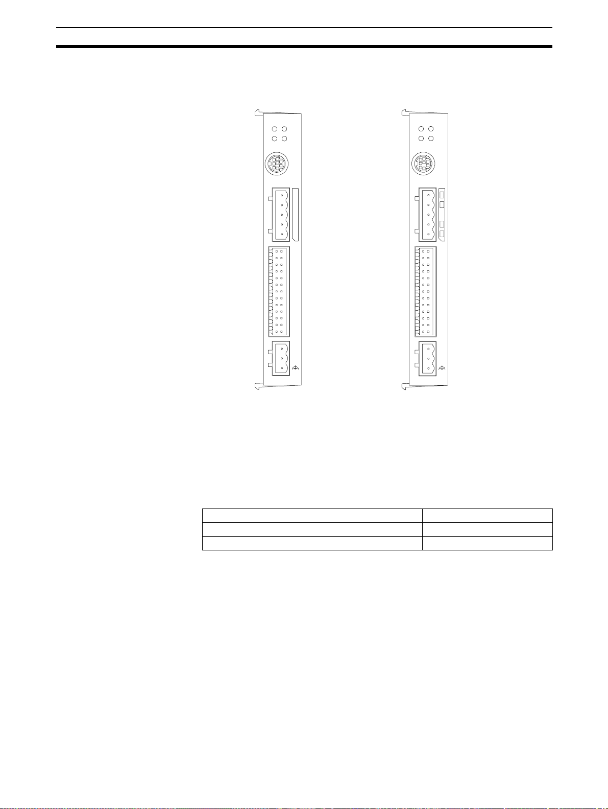
1-1 Features
MCW151-E MCW151-DRT-E
1-1-1 Overview
MCW151
RUN STS
SD RD
1
25
PORT0 ,1
PORT2
2
I/O
26
+24V
0V
MCW151-DRT
RUNMSSTS
1
25
NS
PORT0,1
2
I/O
26
+24V
0V
The R88A-MCW151 is a 1.5-axis Motion Control (MC) Unit which is connected to the W-series Servo Driver. The MC Unit provides direct control of
the Servo Driver, enables both speed and torque control and has ac cess to
detailed Servo Driver data. To support a multi-axis control application, the MC
Unit features both an encoder input and output connection.
There are two types of the MCW151 Motion Controllers, according to the
communication interface which is integrated into the Unit.
Communication Interface Model
RS-422A/485 Serial Communication R88A-MCW151-E
DeviceNet R88A-MCW151-DRT-E
The multi-tasking BASIC motion control language provides an easy to use
tool for programming advanced motion control applications.
Three types of motion control are possible: point-to-point, continuous path
and electronic gearing.
Point-to-point Control Point-to-point (PTP) control enables positioning independently for each axis.
Axis specific parameters and c ommands are us ed to determi ne the p aths for
the axes.
Continuous Path Control Continuous path (CP) control enables the user not only to control the start and
end positions, but also the path between those points. Possible multi-axis
paths are linear interpolation and circular interpolation. Also user defined
paths can be realized with the CAM control.
Electronic Gearing Electronic gearing (EG ) enables controlling an axis as a direct li nk to another
axis. The MC Units supports electronic gear boxing, linked moves and CAM
movements and adding all movements of one axis to another.
2
Page 18

Features Section 1-1
1-1-2 Descr iption of Features
The MC Unit provides the following features.
Motion Control The direct connection to the Servo Driver provides a high performance / high
precision control system. Operation will be processed in optimal synchronization.
• Suppor t s both speed and torque co ntrol modes of the Servo Dr iver.
• Supports switching between the modes during operation.
• Suppor t s speed limit during torque con trol using the speed reference.
• Selectable MC Unit servo period cy cle which can be set to either 0.5 ms
or 1.0 m s.
Servo Driver Access Apart from the motion control operation with the Servo Driver, the MC Unit
provides the following features:
• Monitor the detailed Servo Driver alarm status.
• Monitor various monitor signals (rotation speed, command torque).
• Monitor the Servo Driver digital inputs and a nalog input to i nclude in the
application.
• Read and write of the Servo Driver Parameters.
• Execution of several Driver functions from the MC Unit. Examples are
Print Registration, Origin Search, Driver Alarm Reset and Driver Reset.
Easy Programming with
BASIC Motion Control
Language
Encoder Input and Output To achieve a solution for multi-axis applications, the M C Unit is provided wi th
DeviceNet Interface
(MCW151-DRT-E only)
Serial Communications The MC Unit has three (MCW151-E ) or two (MCW151-DRT-E ) seri al ports for
The multi-task BASIC motion control language is used to program the MC
Unit. A total of 14 programs can be held in the Unit and up to 3 tasks can be
run simultaneously. The MC Unit is programmed using a Windows-based
application called
programming and debugging.
an encoder axis. This axis provides either to have an encoder input for external encoders or to have an encoder output to cascade position data to
another MC Unit.
The MCW151-DRT-E can be connected easily in an existing DeviceNet network. The DeviceNet network has a maximum communication distance of
500 m, so an MC Unit in a remote location can be controlled from the Master.
The MC Unit supports both remote I/O and explicit message communications.
• Remote I/O communications
Remote I/O communications can exchange data (4 input words and 4 output words max.) with the MC Unit at high speed and without programming, just like regular I/O.
• Explicit message commun ications
Large data transfers to a nd from t he M C Unit m emor y can be perform ed
by sending explicit messages from the Master when required.
communication to several external devices. Next to the connection to th e Personal Computer for configuring, the MC Unit can be connected with PCs, Programming Ter minals (PTs) and other MC Units. The serial ports suppor t the
Host Link Master and Slave protocols.
1
Motion Perfect. Motion Perfect allows extremely flexible
Absolute Encoder
Support
By using a S ervomotor with absol ute encoder, the motor position is updat ed
automatically in the MC Unit at start-up of the system. No origin search
sequence will be necessary in the system initiation phase.
1.Motion Perfect is a product of Trio Motion Technology Limited.
3
Page 19

Features Section 1-1
Virtual Axes The MC Unit contains a total of 3 axes, of which two can be configured as vir-
tual axis. The virtual axes are internal axes and are used for computational
purposes. They act as perfect servo axes and are very useful for creating profiles. They can be linked directly to the servo axes.
Hardware-based
Registration Inputs
There is a high-speed registration input for the encoder inp ut and out put axis.
On the rising or falling edge of a regi stration input, th e MC Unit will store the
current position in a register. The registered position can then be used by the
BASIC program as required. T he registered positions are captured in hardware.
General-purpose Input
and Output Signals
Starting, st opping, limit switching, origin sea rches and many other f unctions
can be controlled by the MC Unit. The general I/O can have specific functions
(such as the registration, limit switches), but also can be freely used.
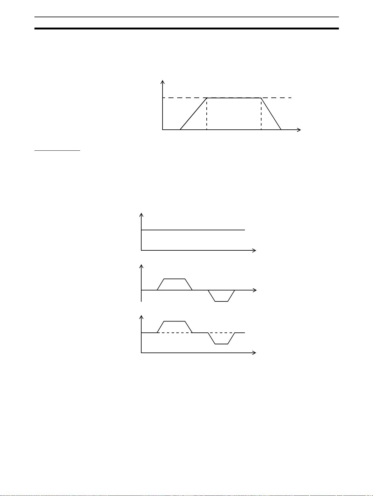
Reduced Machine Wear The traditional trap ezoidal speed prof ile is provided t o ge nerate sm oot h st art-
ing and stopping. The trapezoidal corners can be rounded off to S-curves.
Trapezoidal Speed Profile with
Square Corners
Time
Trapezoidal Speed Profile with
S-curveCorners
SpeedSpeed
Time
4
Page 20
System Configuration Section 1-2
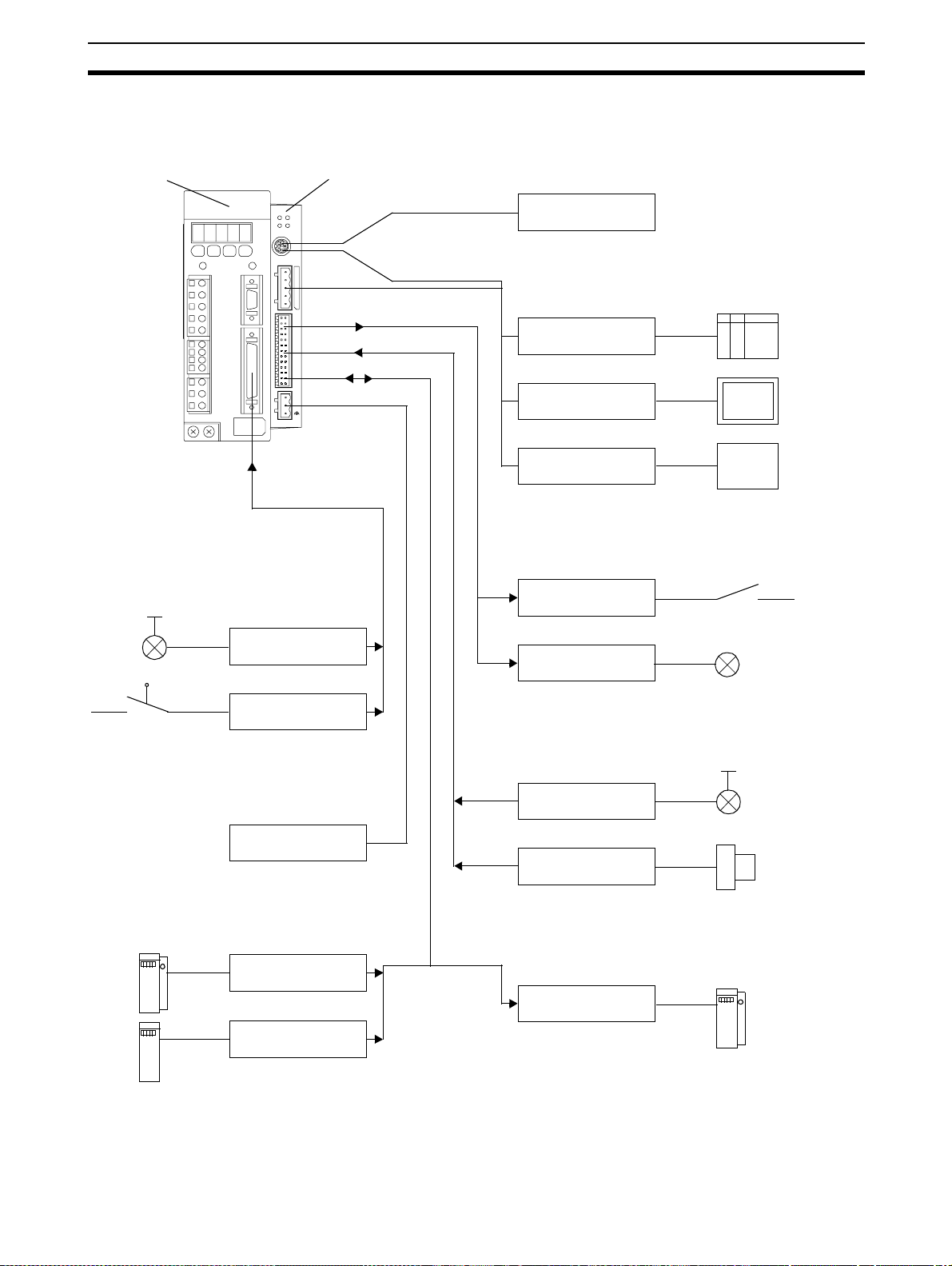
1-2 System Configuration
Basic Configuration
W-series Servo Driver MCW151
Personal Computer running Motion Perfect
MCW151
STS
RUN
SD
RD
PORT2 PO RT0 ,1
1
2
I/O
25
26
+24V
0V
Typical applicable Sensors for Servo
Driver Digital I nputs
Print Registration
Personal
Computer
1
Typicalapplicable Units for Serial Comm. Ports
PC
2
Programmable
Terminal (PT)
General-purpose
device
Typical applicable Actuators for Digital O utputs
Relais
Lamp
Limit Switches
Power Supply connection
24 V Power supply
Typicalapplicable Pulse Generators for
Encoder Input
MCW151 Unit
Servo Driver
Note 1. The RS-422A/485 Serial Port 2 is only available on the MCW151-E Unit.
2. The MC Unit has one encoder axis. Either the encoder input or the encoder
Typical applicable Sensors for Digital Inputs
Print Registration
Proximity Sensor
Typical applicable Units f or Encoder Output
MCW151 Unit
output can be used.
5
Page 21
System Configuration Section 1-2
The equipment and models which can be used in the system configuration
are shown in the following table.
Device Model
Motion Control Unit R88A-MCW151-E
R88A-MCW151-DRT-E
Servo Driver (see note) R88D-WT
Servomotor
Control De vices (using
Host Link)
Personal Computer (for
Motion Perfect)
Motion Perfect Version 2.0 or later
R88M-W
Prog ramma bl e Terminals
CPU Units
IBM Pers onal Computer or 100% compatible
Note The MC Unit must be used with a Servo Driver with software version 14 or
later. The MC Unit cannot be used with software version 8.
❏
❏
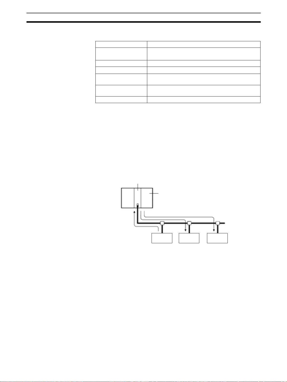
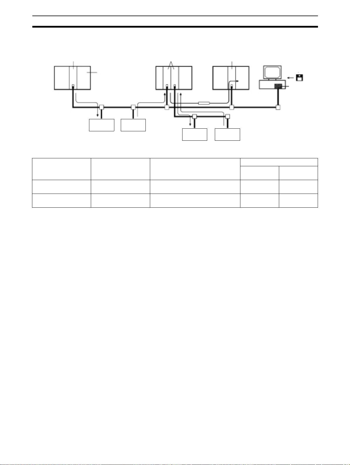
DeviceNet Configuration
(MCW151-DRT-E only)
A DeviceNet system can be constructed in two ways: fixed allocation or free
allocation.
Fixed Allocation
A DeviceNet system can be constructed easily without the Configurator. With
fixed allocation, predetermined words are allocated to each node for the
Slave’s I/O.
An OMRON Master must be used in order to perform fixed allocation. Moreover, with fixed allocation only one M aster Unit can be u sed in a DeviceNet
network and only one Master Unit may be mounted to a PC.
Master Unit
CPU Unit
Remote I/O communications
Slave Slave MC Unit
Free Allocatio n
The Configurator can be used to freely allocate the words used by each
Slave. With free allocation, more than one Master Unit can be connected in a
DeviceNet network and each Master’s Slave I/O can be set independently.
More than one Master Unit may be mounted to each PC and those Masters
can be used independently. Furthermore, other compan ies’ Masters can be
6
Page 22
Motion Control Concepts Section 1-3
used. For details, refer to the DeviceNet Configurator Operation Manual
(W328).
Master Unit Master Unit
CPU Unit
Remote I/O communications
MC Unit
Slave
Master Unit
Message
communications
Slave
MC Unit
The following OMRON Master Units can be used.
Appli c able P C Ma s te r Un it mo d e l
number
CS1 Series CS1-DRM21 CPU Rack or Expansion I/O Rack
(Classified as Special I/O Units)
C200HZ/HX/HG/HE C200HW-DRM21-V1 CPU Rack or Expansion I/O Rack
(Classified as Special I/O Units)
Mounting position Max. number of Units
Note S om e CPUs can control 16 Master Units and other CPUs can control 10.
With
Configurator
16 1
10 or 16 (see
note)
Configurator
ISA Board
Without
Configurator
1
1-3 Motion Control Concepts
The MC Unit offers the following types positioning control operations.
1. Point-to-point control
2. Continuous Path control
3. Electronic Gearing
This section will introduce some of the commands and parameters as used in
the BASIC programming of the motion control application. Refer to
SECTION 6 BASIC Motion Control Programming Language for details.
Coordinate S ys te m Positioning operations performed by the MC Unit are based on an axis coordi-
nate system. The MC Unit converts the position data from either the connected Servo Driver or the connected encoder into an internal absolute
coordinate system.
The engineering unit which specif ies the distances of travelling can be freely
defined for each axis separately. The conversion is performed through the
use of the unit conversion factor, which is defined by the UNITS axis parameter. The origin point of the coordinate system can be det ermined using the
DEFPOS command. Thi s command re-de fines the current position to zero or
any other value.
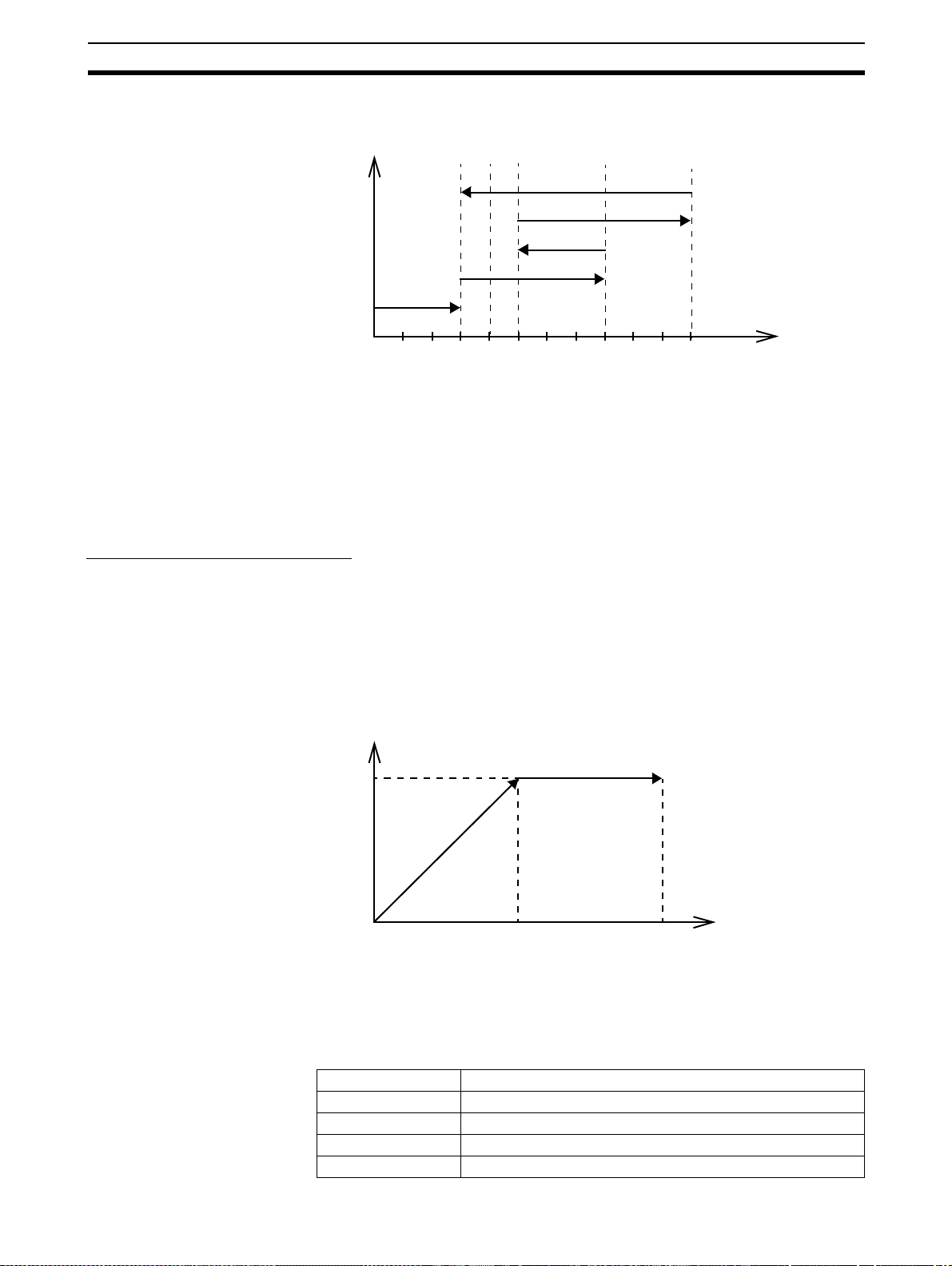
A move is defined in either absolute or relative terms. An absolute move takes
the axis to a specific predefined position with respect to the origin point. A relative move takes the axis from the current position to a position that is defined
relative to this current position. The following diagram shows gives an exam-
7
Page 23
Motion Control Concepts Section 1-3
ple of relative (command MOVE) and absolute (command M OVEABS) linear
moves.
MOVEABS(30)
MOVE(60)
MOVEABS(50)
MOVE(50)
MOVE(30)
1-3-1 PTP-control
In point-to-point positioning, each axi s is moved independently of the other
axis. The MC Unit supports the following operations.
• Relative m o ve
• Absolute move
• Continuous move forward
• Continuous move reverse
Relative and Absolute Moves
To move a single axis either t he command MOVE for a relative move or the
command MOVEABS for an absolute move is used. Each axis has its own
move characteristics, which are defined by the axis parameters.
Suppose a control program is executed to move from the origin to an axis
no. 0 coordinate of 100 and axis no. 1 coordinate of 50. If the speed parameter is set to be the s ame for both axes and the acceleration and dec eleration
rate are set sufficiently high, the m ovements for axis 0 and axis 1 will be as
illustrated below.
Axis 1
0
50
50 100
MOVEABS(100) AXI S(0)
MOVEABS(50) AXIS(1)
Axis position
0
50
100
Axis 0
At start, both the axis 0 and axis 1 will move to a coordinate of 50 over the
same duration of time. At this point, axis 1 will stop and the axis 0 will continue to move to a coordinate of 100.
Relevant Axis Parameters As mentioned before the move of a certain axis is determined by the axis
parameters. Some relevant parameters are given in the next table.
Parameter Description
UNITS Unit conver sion factor
ACCEL Acceleration rate of an axis in units/s
DECEL Deceleration rate of an axis in units/s
SPEED Demand speed of an axis in units/s
2
2
8
Page 24
Motion Control Concepts Section 1-3
D
d
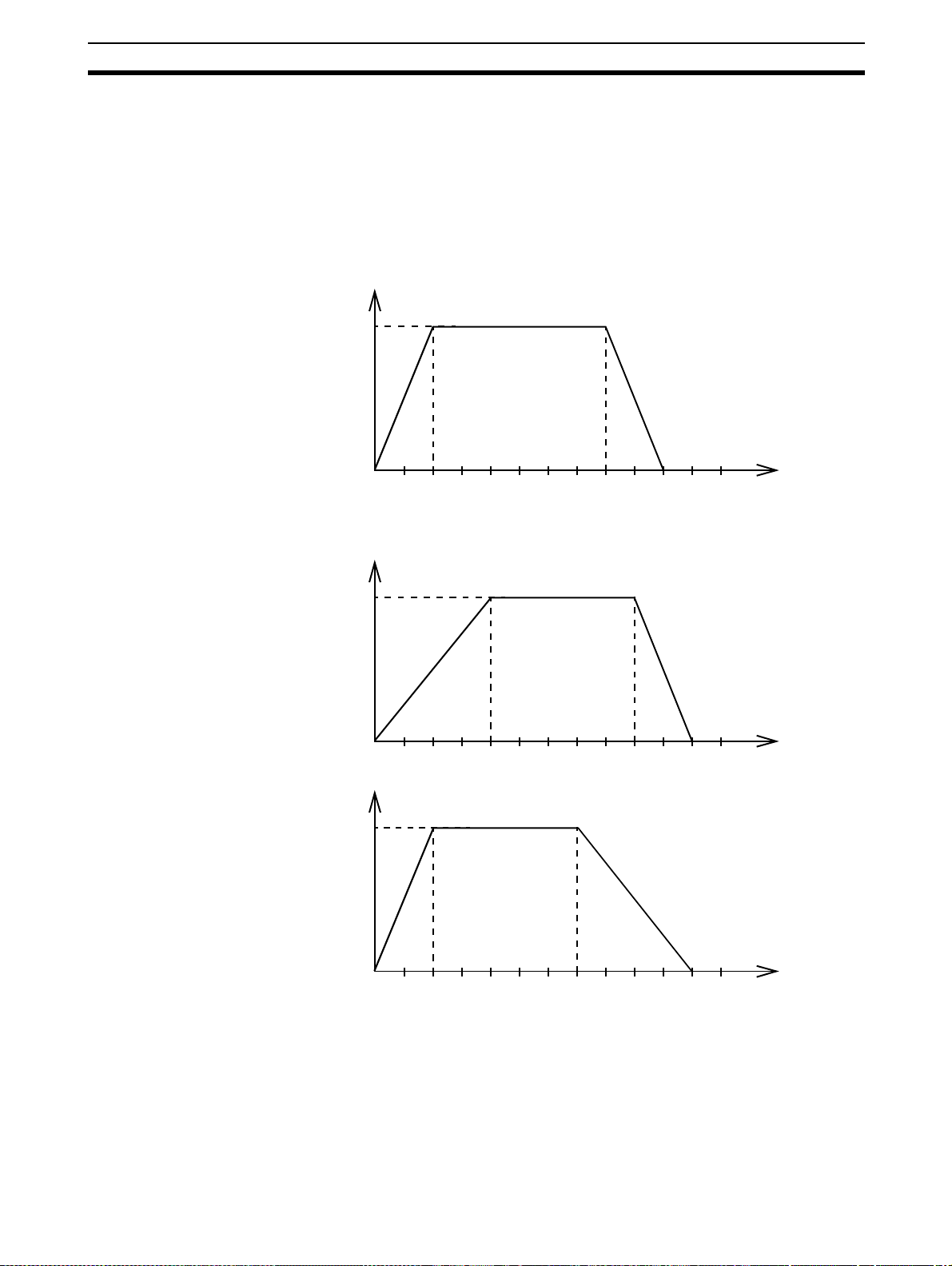
Defining moves The speed profile below shows a simple MOVE operation. The UNITS param-
eter for this axis has been defined for example as meters. The required maximum speed has been set to 10 m/s. In order to reach this speed in one
second and also t o decelerate to zero speed again i n one second, both the
acceleration as the deceleration rate have been set to 10 m/s
tance travelled is the sum of distances travelled during the acceleration, constant speed and decel eration segm ents. Suppose the di stance moved by the
MOVE command is 40 m, the speed profile will be given by the following
graph.
Speed
10
2
. The total dis-
ACCEL=10
DECEL=10
SPEED=10
MOVE(40)
0
12345
6
Time
The following two speed profiles show the same movement with an acceleration time respectively a deceleration time of 2 seconds.
Speed
ACCEL=5
6
DECEL=10
SPEED=10
MOVE(40)
Time
ACCEL=10
DECEL=5
SPEED=10
MOVE(40)
10
Speed
10
0
12345
0
12345
6
Time
Move Calculations The following equations are used to calculate the total time for the motion of
the axes. Consider the moved distance for the MOVE command as , the
demand speed as , the acceleration rate and deceleration rate .
V
a
9
Page 25

Motion Control Concepts Section 1-3
Continuous Moves
Acceleration time
V
---=
a
2
Acceleration dist a nc e
V
------=
2a
Deceleratio n time
V
---=
d
2
Deceleration distance
V
------=
2d
Constant speed distance
V2ad+()
D=
-----------------------–
2ad
D
Total time
The FORWARD and REVERSE commands can be used to start a continuous
movement with constant speed on a cert ain axis. The FORWARD command
will move the axis in positive direction and the REVERSE comman d in negative direction. For these commands also the axis parameters ACCEL and
SPEED apply to specify the acceleration rate and demand speed.
Both movements can be canceled by using either the CANCEL or RAPIDSTOP command. The CANCEL command will cancel the m ove for one axis
and RAPIDSTOP will cancel m oves on all axes. The de celeration rate is set
by DECEL.
Va d+()
--- -=
-------------------- -+
V
2ad
1-3-2 CP-control
Linear Interpolation
Continuous Path control enables to control a specif ied p ath bet ween t he st art
and end position of a movement for one or multiple axes. The MC Unit supports the following operations.
• Linear interpolation
• Circular interpolation
• CAM control
In applications it can be required for a set of motors to perform a move operation from one position to another in a straight line. Linearly interpolated moves
can take place among several axes. The commands MOVE and MOVEABS
are also used for the linear int erpola ti on . I n t h is c as e t h e c o m ma nds will h ave
multiple arguments to specify the relative or absolute move for each axis.
Consider the following three axis move in a 3-dimensional plane.
MOVE(50,50,50)
Axis 2
Axis 1
Speed
Time
10
Axis 0
Page 26

Motion Control Concepts Section 1-3
The speed profile of the motion along the path is given in the diagram. The
three parameters SPEED, ACCEL and DECEL which determine the multi axis
movement are taken from the corresponding parameters of the base axis.
The MOVE command computes the various components of speed demand
per axis.
Circular Interpolation
It may be required that a tool travels from the starting point to the end point in
an arc of a circle. In this instance the motion of two axes is related via a circular interpolated move using the MOVECIRC command. Consider the following
diagram.
CAM Control
MOVECIRC(-100,0,-50,0,0)
-50
The centre point and desired en d point of the trajectory relative to the start
point and the direction of movement are specified. The MOVECIRC command
computes the radius and the angle of rotation . Like the linearly inter polated
MOVE command, the ACCEL, DECEL and SPEED variables associated with
the base axis determine the speed profile along the circular move.
Additional to the standard move profiles the MC Unit also provides a way to
define a position profile for the axis to move. The CAM command will move an
axis according to position values stored in the MC Unit Table array. The
speed of travelling through the profile is determined by the axis parameters of
the axis.
CAM(0,99,100,20)
Axis 1
0
50
50
Axis 0
1-3-3 EG-Control
Position
Time
Electronic Gearing control allows you to create a direct gearbox link or a
linked move between two axes. The MC Unit supports the following operations.
1. Electronic gearbox
2. Linked CAM
3. Linked move
4. Adding axes
11
Page 27
Motion Control Concepts Section 1-3
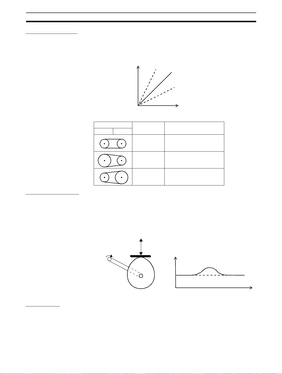
Electronic Gearbox
The MC Unit is able to have a gearbox link from one axis to another as if there
is a physical gearbox connecting them. This can be done using the C ONNECT command in the program. In the command the ratio and the axis to link
to are specified.
CONNECT Axis
2:1
Axes Ratio CONNECT command
01
1:1 CONNECT(1,0) AXIS(1)
2:1 CONNECT(2,0) AXIS(1)
1:1
1:2
Master Axis
Linked CAM control
Linked Move
1:2 CONNECT(0.5,0) AXIS(1)
Next to the standard CAM profiling tool the MC Unit also provides a tool to link
the CAM profile to another axis. The command to create the link is called
CAMBOX. The travelling speed through the profile is not deter mined by the
axis parameters of the a xis but by the position of t he linked axis. This is like
connecting two axes through a cam.
CAMBOX(0,99,100,20,0) AXI S(1)
CAMBOX Axis (1) Position
Master Axis (0) Position
The MOVELINK command provides a way to link a specified move to a master axis. The move is divided into an acceleration, dece leration and constant
12
Page 28
Motion Control Concepts Section 1-3
speed part and they are specified in master link distances. This can be particularly useful for synchronizing two axes for a fixed period.
MOVELINK(50,60,10,10,1) AXIS(0)
Speed
Master Ax is (1)
Synchronized
MOVELINK Axis (0)
Time
Adding Axes
It is very useful to be able to add all movements of one axis to another. One
possible application is for instance changing the offset between two axes
linked by an electronic gearbox. The MC Unit provides this possibility by using
the ADDAX command. The movements of the linked ax is will consists of all
movements of the actual axis plus the a dditional movements of the master
axis.
Speed axis 0*
BASE(0)
ADDAX(2)
FORWARD
MOVE(100) AXIS(2)
MOVE(-60) AXIS(2)
Speed axis 2
Time
+
Speed axis 0
Time
=
Time
1-3-4 Other Operations
Canceling Moves In normal operation or in case of emergency it can be necessary to cancel the
current movement from the buffers. When the CANCEL or RAPIDSTOP commands are given, the selected axis respectively all axes will cancel their current move.
Orig in Sea rch The encoder feedback for controlling the position of the motor is incremental.
This means that all movement must be defined with respect to an origin point.
The DATUM comm and is used to set up a procedure whereby the MC Unit
goes through a sequence and searche s for the origin based on digital inputs
and/or Z-marker from the encoder signal.
13
Page 29

Control System Configuration Section 1-4
Print Registration The MC Unit can capture t he position of an axis in a regi ster when an event
occurs. The event is referred to as the print registration input. On the risin g or
falling edge of an input signal, which is either the Z-marker or an input, the MC
Unit captures the position of an axis in hardware. This position can then be
used to correct possible error between the actual position and the desired
position. The print registration is set up by using the REGIST command.
The position is captured in hardware, and therefore there is no software overhead and no interrupt service routines, eliminating the nee d to deal with the
associated timing issues.
Merging Move s If the MERGE axis parameter is set to 1, a movement will always be followed
by a subsequent movement without stopping. The following illustrations will
show the transitions of two moves with MERGE value 0 and value 1.
Speed
MERGE=0
Time
Speed
MERGE=1
Time
Jogging Jogging moves the axes at a constant speed forward or reverse by manual
operation of the digital in puts. Different speeds are also selectable by input.
Refer to the FWD_JOG, REV_JOG and FA ST_JOG axis parameters.
1-4 Control System Configuration
1-4-1 Servo System Principles
The servo system used by and the internal operation of the MC Unit are
briefly described in this section. Refer to 2-4 Servo System Precautions fo r
precautions related to servo system operation.
Semi-closed Loop System The servo system of the MC Unit uses a semi-closed or inferred closed loop
system. This system detects actua l m ac hin e movements b y th e ro tation of the
motor in relation to a t arget value. It calculates the error between the target
value and actual movement, and reduces the error through feedback.
14
Page 30
Control System Configuration Section 1-4
Internal Operation of the
MC Unit
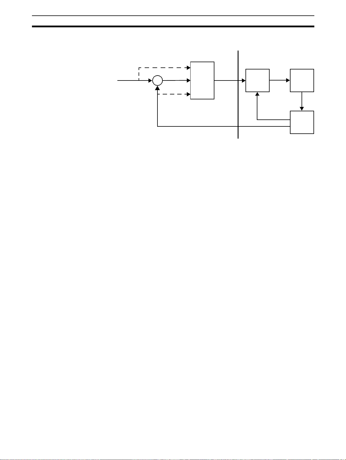
1,2,3... 1. The MC Unit performs actual position c ontrol. The main inpu t of the con-
MC Unit
Servo System
2
3
Demand
position
1
+
-
Position
Control
Speed
reference
Speed
Control
Motor
4
Measured
speed
Encoder
Measured
position
Inferred closed loop systems occupy the mainstream in modern servo systems applied to positioning devices for industrial applications. The following
graph shows the basic principle of the Servo System as used in the MC Unit.
troller is the following error, which is the calculated difference between the
demand position and the actual measured position.
2. The Position Controller calculates the required speed reference output determined by the following error and possibly the dema nded position and
the measured position. The speed reference is provided to the Servo Driver.
3. The Servo Driver controls the rotational speed of the Servomotor corresponding to the speed reference. The rotational speed is proportional to
the speed reference.
4. The rotary encoder wil l generate the feedback pulses for both the speed
feedback within the Servo Driver speed loop and the position feedback
within the MC Unit position loop.
Motion Control Algorithm The servo system controls the m otor by continuously ad justing t he s pee d ref -
erence to the Servo Driver. The speed reference is calculated by the MC
Unit’s Motion Control algorithm, which is explained in this section.
The Motion Control algorithm uses th e demand position, the measured posi tion and the following error to determine the speed reference. The following
error is the difference between the d emanded and measured position. The
demand position, me asured position and following error are represented by
axis parameters MPOS, DPOS and FE. Five gain values have been implemented for the user to be able to configure the correct control operation for
each application.
15
Page 31

Control System Configuration Section 1-4
The Motion Control algorithm of the MC Unit is shown in the diagram below.
K
∆
vff
K
p
K
ov
Output
signal
∆
Measured
position
Demand
position
Proportional Gain The proportional gain creates an output that is proportional to the
foll owing er ror .
O
All practical systems use proportional gain. For many just using this gain
parameter alone is sufficient. The proportional gain axis parameter is called
P_GAIN.
Integral Gain The integral gain creates an output that is proportional to the sum of
the following errors that have occurred during the system operation.
O
Integral gain can cause overshoot and so is usually used only on systems
working at constant speed o r with slow accelerations. The integral gain axis
parameter is called I_GAIN.
KpE⋅=
p
K
i
Following
error
+
K
Σ
K
i
∆
d
-
K
p
++
O
p
E
K
i
O
i
E
E
⋅=
i
å
Derivative Gain The derivative gain produces an output that is proportional to the
change in the following error and speeds up the response to changes in
error while maintaining the same relative stability.
d
ov
vff
K
K
K
d
ov
vff
O
Derivative gain may create a smoother response. High values may lead to
oscillation. The derivative gain axis parameter is called D_GAIN.
Output Speed Gain The output speed gain produce s an output that is proportional to
the change in the measured position and increases system damping.
O
The output speed gain can be us eful for smoothing motions but will gene rate
high following errors. The output speed gain axis parameter is called
OV_GAIN.
Speed Feedforward Gain The speed feedforward gain produces an output that is propor-
tional to the change in dem and position and minimizes the following error
at high speed.
O
The parameter can be set to minimise the following error at a constant
machine speed after ot her gai ns have been set. Th e speed feed forward gain
axis parameter is called VFF_GAIN.
K
d
O
d
E
E∆⋅=
K
ov
P
m
O
ov
Pm∆⋅=
K
vff
P
d
O
vff
Pd∆⋅=
16
Page 32

Control System Configuration Section 1-4
De faul t Val u es The default settings are given below along with the resulting profiles. Frac-
tional values are allowed for gain settings.
Gain Default
Proportional Gain 0.1
Integral Gain 0.0
Derivative Gain 0.0
Output Speed Gain 0.0
Speed Feedforward Gain 0.0
1-4-2 Encoder Signals
Standard OMRON equipment is designed for an advanced phase-A for forward rotation and an advanced phase-B for reverse rotation. For the encoder
input and output signals, the MC Unit is designe d to comply with this phase
definition, allowing the M C Unit to be connect ed to other equipment without
problems.
With this arrangement, the direction of rotation can be easily detected by
monitoring the relative phase of both signals. If channel A leads channel B,
indicating clockwis e (CW ) movement, th e counter w ill increm ent. Co nversely,
if channel B leads channel A, indicating counterclockwise (CCW) movement,
the counter will decrement.
Typically, rotar y en coders also provide an addi tional Z-marker as a reference
pulse within each revolution. By properly decoding and counting these
encoder signals, the direction of motion, speed, and relative position can be
determine d.
Encoder input For the MC Unit encoder input, the pulse ratio is 4. Ev ery encoder edge (pulse
edge for either A or B phase) is one internal count.
Forward rotation (CW) Reverse rotation (CCW)
Phase A
Phase B
01 423 567 76 354 210
Counts (x4)
The signals A, B and Z appear physically as A+ and A-, B+ and B- and Z+ and
Z-. These appear as differential signals on twisted-pair wire inputs, ensuring
that common m odes are rejected and that the noise level is kept to a minimum.
When using encoders by other makers, check carefully the encoder specification for phase advancement. If the definition differs from the ones given
above, reverse the B-phase wiring between the MC Unit and the Servo Driver.
In most case, this should resolve the problem.
17
Page 33

Control System Configuration Section 1-4
Encoder ou tput For encoder output, the pulse ratio is 64. For every 16 inter nal counts one
encoder edge for one of the two phases will be produced.
Phase A
Phase B
Phase Z
016 6432 48 80 96
Internal Counts
The Z-phase signal has the following specification:
• The Z-marker has a period of 4096 generated edges.
• The pulse has a width of a quarter pulse period length (when both phase
A and B are low).
• The Z-phase signal is active after power-on.
The generated frequency is limited to the maximum allowable frequency. If
the internal speed would result in a frequenc y above this maximum, an axis
status flag will be set. See 8-2-1 MC Unit Error Handling for details.
18
Page 34

Specifications Section 1-5
1-5 Specifications
1-5-1 General Specifications
The MC Unit provides the following general specifications.
Item Contents
Applicable Servo Driver R88D-W Series (software version 14 or later, see note)
Servomotors Type R88M-W Series
Encode r Incremental / Absolute
Installati on M ethod Mounted on the CN10 connector on the Servo Driver
side.
Basic Specificat ions Power Supply Method 5 VDC (supplied from the control power supply of the
Servo Driver)
24 VDC (supplied from ext ernal power supply)
Total Power Consumption 4.0 W
External Dimensions 20 x 142 x 128 mm (H x W x D)
Approx. Mass 200 g
Current Consumption 170 mA for 24 VDC
Output Power Supply 5 VDC, maximum 160 mA (to external encoder)
Environment Ambient Operating Tem-
perature
Ambient Operating
Humidity
Ambient Atmosphere Free from corrosive gasses
Ambient Storage Temper-
ature
Ambient Storage Humi dity 90 % RH or less (non-condensing)
Vibration Resistance 4.9 m/s
Impact Resistance Acceleration 19.6 m/s2 or less (when the impact is
0 to 55
°C
90 % RH or less (non-condensing)
-20 to 75
applied three times in each X, Y, Z direction )
°C
2
Note T he MC Unit cannot be used with software version 8.
1-5-2 Functional Specifications
The MC Unit provides the following functional specifications.
Item Contents
Type of Unit Optional board for W-series Servo Driv er
Motion Control Speed Control Inferred closed loop with PID , out put speed and speed
Torque Control Torque referen ce
Control Switch Speed / Torque control switching during operation
Configuration Maximum No. of axes 3
No. of contr olled servo
axes
Maximum No. of encoder
in- or output axes
Maximum No. of virtual
axes
Servo Loop Cycle Selectable to 0.5 ms or 1.0 ms.
Measurement Units User definabl e
feed forward gains
Speed reference (open loop)
Possi ble torque limit oper ation
Possi ble speed limit operation
1
1
2
19
Page 35

Specifications S ecti on 1-5
Item Contents
Positioning operations Linear interpolation Linear interpolation for any num ber of axes
Circular interpolation Circular interpolation for any two axes
CAM profile CAM profile movement for any axis
Electronic gearbox Electronic gearbox link between any two axes
Linked CAM Linked CAM profile movement for any two axes
Linked mo ve Linked move for any two ax es
Adding axes Adding any two axes
Acceleration/decelerati on curves Trapezoidal or S-curve
Servo Driver Access Motion Control Speed Control
Torque Control
Pos ition Feed-back
Driver Enable
Driver Print Registration
Monitoring Driver Alarm and Warning Status
General Driver Status
Driver Digital Input
Driver Analogue Input
Driver Limit Switches
General C o ntrol D r ive r A larm Reset
Driver Reset
Par am eter Access Read and Write Pn-paramet ers
Read U n p arameters
External connected devices Personal Computer with Motion Perfect Programming
Software
Serial Communications RS-232C Port 0:
Connection to PC (Motion Perfect Software)
Port 1:
Host Link Master pr otocol
Host Link Slave protocol
General-purpose
RS-422A/485 (MCW151E only)
External
I/O
Switch setting DeviceNet settings (MCW151-DRT-E only)
Power supply for general and axis I/O Provided externally
Encoder Input Line receiver input; maximum response frequency:
Encoder Output Line recei ve output; maximum frequency:
Digital Input s Total of 8 digital inputs can be wired and used for
Digital Outputs Total of 6 digital outputs can be wired and used for
Registrat ion inputs Two registration input s can be used (s imu ltaneo usly) t o
Port 2:
Host Link Master pr otocol
Host Link Slave protocol
General-purpose
1500 kHz pulses (before multip li cation)
Pulse multip l ic at io n :
x4
500 kHz pulses
Internal counts to output pulse ratio:
64 : 1
instance for limit switches, emergency stop and proximity inputs. Two inputs can be used for registration of
the encoder input /output axis.
position dependent switching or other general purposes.
capture the position in hardware .
General purpose (MCW151-E onl y)
20
Page 36

Comparison between Firmware Versions Section 1-6
Item Contents
Task program management
Saving program data MC Unit Random Access Memory (RAM) and Flash memory
Self diagnostic functions Detection of memory corruption via checksum
Programming language BASIC
Number of tasks Up to 3 tasks running simultaneously plus the Com-
mand Line task
Max. number of programs 14
Data storage capac it y 251 (VR) + 8000 (Table) max.
backup. (See note)
Personal Computer Motion Perfect software manages a backup on the
hard disk of the personal computer.
Detection of error counter overrun
Note The service life for the flash memory is 100,000 writing operations.
1-5-3 DeviceNet Specifications (MCW151-DRT-E only)
The MC Unit provides the following DeviceNet specifications.
Item Contents
Communications protocol DeviceNet
Supported connections (comm unications) Master-Slave: Remote I/O and explicit messages
Both conform to DeviceNet specifications
Connection forms (see note) Combination of multi-drop and T-branch connections
(for trunk or drop lines)
Baud rate 500 kbps, 250 kbps, 125 kbps (switchable)
Communications media Special 5-wire cables (2 signal lines, 2 power lines, 1
shield line)
Communications distances
Communications power supply 11 to 25 VDC (Supplied from the communications con-
500 kbps Network l ength: 100 m max. (100 m max.)
Drop line length: 6 m max.
Total drop li ne length: 39 m max.
250 kbps Network l ength: 250 m max. (100 m max.)
Drop line length: 6 m max.
Total drop li ne length: 78 m max.
125 kbps Network l ength: 500 m max. (100 m max.)
Drop line length: 6 m max.
Total drop li ne length: 156 m max.
Parentheses indicate the length when Thin Cables are used.
nector)
Note Terminating resistors are required at both ends of trunk line.
Refer to the DeviceNet Operation Manual (W267) for other communication
specifications, such as communication cycle times.
1-6 Comparison between Firmware Versions
The following table shows a comparison between the two current versions of
the R88A-MCW151-E and R88A-MCW151-DRT-E Motion Control Units. The
changes are only related to firmware (not hardware) and the firmware is common for both types. Verify the current version of the MC Unit using the VERSION parameter.
21
Page 37

Comparison between Firmware Versions Section 1-6
!Caution
Commands and
instructions
DeviceNet
(MCW151-DRT-E
only)
The R88A-MCW151-E FW 1.62 is fully backward compatible with the previous version FW 1.61. For the R88A-MCW151-DRT-E FW 1.62 many
DeviceNet implementation changes have been done. For both Units caution
must be taken when upgrading.
Item FW 1.61 FW 1.62
ADD_DAC No. Yes.
Command to enable dual feedback control.
Softwa re reset of
MC Unit
Explicit message s
(read and write)
Device object s - Update of Device objects.
Possible by either bit in
Remote I/O O u tp u t word 1 or
Explicit Message command
RESET.
Different maximum transfer
amount for re ad and writ e.
Po ssibl y o n ly by Ex p licit Message command RESET.
Maximum amount of el em ents
to transfer (read/write) is 39
(three-word format) and 119
(one-word format).
See 4-2-2 Explicit DeviceNet
Messages.
See Appendix B Devi ce Proto-
col (MCW151-DRT-E only).
22
Page 38

SECTION 2
Installation
This sectio n des cribes the MC Unit componen ts and provides the information required for installing the MC Unit.
2-1 Components and Unit Settings . . . . . . . . . . . . . . . . . . . . . . . . . . . . . . . . . . . . 24
2-2 Installation. . . . . . . . . . . . . . . . . . . . . . . . . . . . . . . . . . . . . . . . . . . . . . . . . . . . 28
2-2-1 Installation Conditions . . . . . . . . . . . . . . . . . . . . . . . . . . . . . . . . . . . 28
2-2-2 Installation Method. . . . . . . . . . . . . . . . . . . . . . . . . . . . . . . . . . . . . . 28
2-2-3 Dimensions . . . . . . . . . . . . . . . . . . . . . . . . . . . . . . . . . . . . . . . . . . . . 29
2-3 Wiring . . . . . . . . . . . . . . . . . . . . . . . . . . . . . . . . . . . . . . . . . . . . . . . . . . . . . . . 30
2-3-1 Control Connections. . . . . . . . . . . . . . . . . . . . . . . . . . . . . . . . . . . . . 30
2-3-2 Serial Port Connections . . . . . . . . . . . . . . . . . . . . . . . . . . . . . . . . . . 31
2-3-3 DeviceNet Connection . . . . . . . . . . . . . . . . . . . . . . . . . . . . . . . . . . . 36
2-3-4 I/O Specifications . . . . . . . . . . . . . . . . . . . . . . . . . . . . . . . . . . . . . . . 36
2-3-5 Connection examples . . . . . . . . . . . . . . . . . . . . . . . . . . . . . . . . . . . . 38
2-4 Servo System Precautions . . . . . . . . . . . . . . . . . . . . . . . . . . . . . . . . . . . . . . . . 39
2-5 Wiring Precautions . . . . . . . . . . . . . . . . . . . . . . . . . . . . . . . . . . . . . . . . . . . . . 40
23
Page 39

Components and Unit Settings Secti on 2-1
2-1 Compone nts and Unit Sett ings
The following diagram shows the main components of the MC Unit.
Indicators
MCW151
RUN ST S
SD RD
Indicators
MCW 15 1 -DRT
RUNMSSTS
NS
RS-232C Ports
PORT 0 , 1
Connector
PORT 0 , 1
RS-422A/485 Port
Connector
25126
PORT2
2
I/O
+ 24V
0V
DeviceNet
Connector
I/O Connector
Power Connector
25126
2
I/O
+ 24V
0V
The following table describes the indicators on the front of the MC Unit.
■ Motion Control
Indicator Color Status Meaning
RUN Green ON The MC Unit is operating normally.
OFF The M C Unit did not s tart properly or is not pow-
ered on.
Flashing with
STS
STS Red ON The axis has been disabled. The Servo Enable
OFF The axis is enabled.
Flashing alone A motion error has occurred. The Servo Driver
Flashing with
RUN
An error occ urred in th e commu nicati on wit h the
Servo Driver.
is not ON.
has been disabled.
An error occ urred in th e commu nicati on wit h the
Servo Driver.
24
■ RS-422A/485 (MCW 151-E only)
Indicator Color Status Meaning
SD Green ON Transmitting data.
OFF No co mmunication.
RD Green ON Receiving data.
OFF No co mmunication.
Page 40

Components and Unit Settings Section 2-1
■ D eviceNet (MCW151-DRT-E only)
Indi
Color Status Definition Meaning
cator
MS Green ON Device
Operational
Flashing Device in
Standby
Red ON Unrecover-
able Fault
Flashing Minor Fault Switch settings incor rect.
--- OFF No Unit
Power
NS Green ON Link OK.
Online, Connected.
Flashing Online, Not
connected
Red ON Cr itical Link
Failure
Flashing Connection
Timeout
--- OFF No Fieldbus
Power / Not
Online
Normal operating status.
Reading switch settings.
Unit hardware error: Watchdog timer error.
Unit power is not supplied, waiting for initial
processing to st art, or the Unit is being reset.
Network is operating normally (communications established).
Network is operating normally, but communi cations have not yet been established.
A fatal communications error has occurred.
Network communications are not possible.
Communications timeout.
Checking for node address duplication on the
Master, switch sett ings are incorrect, or fieldbus powe r is not supplied.
Switch Settings
The MCW151 Units are equipped with the following DIP-switches.
■ D eviceNet Switch Settings (MCW151-DRT-E only)
The external switch settings will set the Slaves’ node address setting and
baud rate setting.
ON
1 2
1 NA0
NA1
2
3
NA2
NA3
4
NA4
5
NA5
6
MD0
7
NC
8
DR0
9
DR1
10
ON
3
4
56
7
8910
Node address
The node addres s of the slave is set with pins 1 through 6 o f the DIP switch.
Any node address within the setting range can be used as long as it is not
already set on another node.
25
Page 41

Components and Unit Settings Section 2-1
DIP sw itch settin g Nod e ad dress
Pin 6 Pin 5 Pin 4 Pin 3 Pin 2 Pin 1
0000000 (default)
0000011
0000102
... ...
11110161
11111062
11111163
0: OFF, 1: ON
Baud rate
Pins 9 and 10 are used to set the baud rate as shown in the following table.
Pin 10 Pin 9 Baud rate
OFF OFF 125 kbps (default)
OFF ON 250 kbps
ON OFF 500 kbps
ON ON Not allowed
Note 1. Always turn OFF the MC Unit’s power supply (including the commu nica-
tions power supply) before changing the baud rate setting.
2. Set the same baud rate on all of the nodes (master and slaves) in t he Network.
Other settings
Pin 7 is used to select the I/O Slave Messaging mode. This determine s the
allocation of the I/O Slave Messaging mode area.
Pin 7 I/O Slave Messaging Mode
OFF Mode I (default)
ON Mode II
Pin 8 is not used.
■ General Switch Settings (MCW151-E only)
ON
1
1SW1
SW22
SW33
SW44
5
SW5
SW66
SW77
SW88
9
SW9
SW1010
2
3
4
56
7
8910
ON
For the MCW151-E the external DIP switch can be used for general purpose.
The value of the switch can be accessed using the SWITCH_STATUS parameter.
26
Page 42

Components and Unit Settings Section 2-1
DIP switch setting Parameter
Pin 10Pin 9Pin 8Pin 7Pin 6Pin 5Pin 4Pin 3Pin 2Pin
1
00000000000 (default)
00000000011
00000000102
... ...
11111111011021
11111111101022
11111111111023
0: OFF, 1: ON
■ Internal Switches
value
SW2
123ON4
SW3
ON
3
4
12
SW2
123ON4
SW3
123ON4
Switch SW2 (MCW151-E only)
Pin 1 and 2 select the serial communication for port 2.
Pin 2 Pin 1 Selection
OFF OFF RS-422A (defaul t)
ON ON RS-485
Other not allowed
Pin 3 selects the ter mination resistor between receive pins (RD+ / RD -) for
port 2.
Pin 3 Selection
OFF Termination disabled (default)
ON Termination enabled
Pin 4 is not used.
Switch SW3
Pin 1 through 3 enable the ter mination resistor for the encoder channel A, B
and Z.
Pin 3
(channel Z)
Pin 2
(channel B)
Pin 1
(channel A)
Selection
OFF Termination disabled for channel
(default)
ON Termination enabled
Pin 4 is not used.
27
Page 43

Installation Section 2-2
2-2 Installation
2-2-1 Installation Condi tions
Follow the procedure below to install multiple Servo Drivers side by side in a
control panel.
Fan Fan
MCW151
STS
RUN
SD
RD
PORT2 PORT 0 ,1
1
2
I/O
25
26
+24V
0V
MCW151
STS
RUN
SD
RD
PORT2 PORT 0 ,1
1
2
I/O
25
26
+24V
0V
MCW151
STS
RUN
SD
RD
PORT2 PORT 0 ,1
1
2
I/O
25
26
+24V
0V
RUN
SD
1
25
MCW151
STS
RD
PORT2 PORT 0 ,1
2
I/O
26
+24V
0V
50 mm min.
30 mm min. 10 mm min. 50 mm min.
■ Servo Driver Orientation
Install the Servo Driver perpen dicular to the wall so that the front panel (display and setting section) faces forward.
■ Cooling
As shown in the figure above, provide sufficient space around each Ser vo
Driver for cooling by cooling fans or natural convection.
■ Side-by-side Installation
When installing Ser vo Dr ivers side-by-side as shown i n t he figure above, provide at least 10 mm between and at least 50 mm above and below each
Servo Driver. Install cooling fans above the Servo Drivers to avoid excessive
temperature rise and to maintain even temperature inside the control panel.
■ Environmental Conditions
• Ambient operating temperature: 0 to 55°C
• Ambient operating humidity: 20% to 90% RH (no condensation)
• Vibration: 4.9 m/s
2
2-2-2 Installation Method
When installing the MC Unit
1,2,3... 1. Insert the lower two extensions into the bottom mounting holes on the right
side of the Servo Driver.
2. Move the upper side of the MC Unit towards the Driver and verify the Servo
Driver connector will directly fit into the MC Unit connector. Click the higher
extension into the upper mounting hole.
28
Page 44

Installation Section 2-2
M
C
W
1
5
1
R
U
N
S
T
S
S
D
R
D
1
,
0
T
R
O
P
2
T
R
O
P
1
2
I
/
O
2
5
2
6
+
2
4
V
0
V
When removing the MC Unit, press down the top of the MC Unit case and
remove the upper extension from the Driver.
2-2-3 Dimensions
The basic dimensions of the MC Unit are shown below .
MCW151
STS
RUN
SD RD
PORT0, 1
PORT2
2
I/O
25126
+ 24V
0V
SW11
SW2
2
3SW3
4SW4
SW5
5
6
SW6
7
SW7
8
SW8
9
SW9
10
SW10
ON
ON
132
81097654
29
Page 45

Wiring Section 2-3
2-3 Wiring
2-3-1 Control Connections
I/O Connector
The I/O Connector is used for wiring to the digital I/O and the conne ction for
the encoder input or encoder output. Refer to 2-3-4 I/O Specifications for electrical specifications.
Connector pin
arrangement
1
25
2
26
I/O
A+ 1 2 AB+ 3 4 BZ+ 5 6 Z-
0V_ENC 7 8 5V_ENC
I0 / R0 9 10 FG
I2 11 12 I1 / R1
I4 13 14 I3
I6 15 16 I5
0V_IN 17 18 I7
O8 19 20 O9
O102122O11
O122324O13
0V_OP 25 26 24V_OP
I/O Connec tor Pin
Functions
Pin Signal
Name Function
1 A+ Encoder phase A+ (Input / Output)
2 A- Encoder phase A- (Input / Output)
3 B+ Encoder phase B+ (Input / Output)
4 B- Encoder phase B- (Input / Output)
5 Z+ Encoder phase Z+ (Input / Output)
6 Z- Encoder phase Z- (Input / Output)
7 0V_ENC Encoder 0V common
8 5V_ENC Encoder 5V power supply output
9 I0 / R0 (Registration) Input 0
10 FG Frame Ground
11 I2 Input 2
12 I1 / R1 (Registrat ion) Input 1
13 I4 Input 4
14 I3 Input 3
15 I6 Input 6
16 I5 Input 5
17 0V_IN Inputs 0V common
18 I7 Input 7
19 O8 Output 8
20 O9 Output 9
21 O10 Out put 10
22 O11 Out put 11
23 O12 Out put 12
24 O13 Out put 13
25 0V_OP Outputs 0V common
26 24V_OP Outputs 24V power supply input
30
Page 46

Wiring Section 2-3
I/O Connector Type Weidmüller B2L 3.5/26 SN SW (included in package)
Wiring Instruc t ions
1
2
3
Power Connect or
The Power Connector is used to connect the 24V power supply to the MC
Unit.
Connector pin
arrangeme nt
+24V
0V
Pin Name Function
1 +24 V Power Supply 24V
2 0 V Power Supply 0V
3 FG Frame Ground
Power Connector Type Phoenix MSTB 2.5/3-ST-5.08 (included in package)
2-3-2 Serial Port Connect ions
RS-232C Connections
The MC Unit has t wo serial RS-232C por ts for communication with external
devices.
Pin Symbol Name Port Direction
1- Not used 2 RS-1 Request to send 1 Output
3
6
1
4
7
2
8
5
PORT0,1
RS-232C Interface Specifications
Item Specifications
Electrical char acteristics Conform to EIA RS-232C
Synchronization Start-stop synchronization (asynchronous)
Baud rate 1200 / 2400 / 4800 / 9600 / 19200 / 38400 bps
Transmission Format Databit Length 7 or 8 bit
Transmission Mode Point-to-poi nt (1:1)
3 SD-0 Send data 0 Output
4 SG-0 Signal ground 0 5 RD-0 Receive data 0 Input
6 SD-1 Send data 1 Output
7 SG-1 Signal ground 1 8 RD-1 Receive data 1 Input
Stop Bit 1 or 2 bit
Parit y B it Even/ O dd/None
31
Page 47

Wiring Section 2-3
Item Specifications
Transmission Protocol Port 0 Motion Perfect Protocol
Port 1 Host Link Protocol (Master / Slave)
General-purpose
Galvanic Isolation No
Connector type 8-pi n mini DIN
Communication buffers 254 bytes (port 1)
Recommended Cables R88A-CCM002P4 Programming Por t 0 Connection Cable to Personal
Computer
R88A-CCM001P5-E Splitter cable for serial ports 0 and 1
Cable length 15 m max.
RS-422A/485 Connection (MCW151-E only)
The MCW151-E has one serial RS-422A/485 port for communication with
external devices.
Pin Symbol Name Port Direction
1 RD- Recei ve data (-) 2 Input
2 RD+ Receive data (+) 2 Input
PORT2
3 FG Frame Ground 2 4 SD- Send da ta (-) 2 Outp u t
5 SD+ Send data (+ ) 2 Ou t p ut
RS-422A/485 Interface Specifications (MCW151-E only)
Item Specifications
Elec trical ch aract er istics Conform to EIA RS - 422A/485
Synchronizati on Start-stop synchronization (asynchronous)
Baud rate 1200 / 2400 / 4800 / 9600 / 19200 / 38400 bps
Transmission Format Databit Length 7 or 8 bit
Stop Bit 1 or 2 bit
Parity Bit Even/Odd/None
Transmission Mode Point-to-mu ltipoint (1:N)
Transmission Protocol RS-422A Host Link Protocol (Master / Slave)
General Purpose
RS-485 General Purpose
Galvanic Isolation Y es
Connector type Phoenix MSTB 2.5/5-ST-5.08 (included in package).
Communication buffers 254 bytes
Flow control None
Terminator Yes, internal 220 selectable by DIP-switch SW2
Cable length 500 m max.
Ω
32
Page 48

Wiring Section 2-3
Connection Examples
■ D irect Connections Using RS-232C Port 0
IBM PC/AT or Compatible Computer s
Computer
RD 2
RS-232C
Interface
SD 3
GND 5
RS 7
CS 8
FG Shell
D-sub 9-pin
connector (male)
■ D irect Connections Using RS-232C Port 1
MC Unit
RS-1 2
RS-232C
Interface
SD-1 6
SG-1 7
RD-1 8
FG Shell
Signal Pin
Programming Terminal (PT)
Signal Pin
MC Unit
Pin Signal
3SD-0
4SG-0
RS-232C
Interface
5 RD-0
Shell FG
mini-DIN 8-pin
connector (male)
Programmable Terminal (PT)
Pin Signal
2SD
3RD
4RS
RS-232C
Interface
5CS
9SG
mini-DIN 8-pin
connector (male)
Note M C Unit Communication Mo de: Host Link Slave
PC
MC Unit
Signal Pin
RS-1 2
RS-232C
Interface
SD-1 6
SG-1 7
RD-1 8
FG Shell
mini-DIN 8-pin
connector (male)
Note M C Unit Commu nication Mo de: Host Link Master
D-sub 9-pin
connector (male)
PC
Pin Signal
2SD
3RD
4RS
5CS
9SG
Shell FG
D-sub 9-pin
connector (male)
RS-232C
Interface
33
Page 49

Wiring Section 2-3
■ 1:N Connections Using RS-232C Port 1
Use the NT-AL001-E Converter Link Adapter
NT-AL001
MC Unit
Signal Pin
Pin Signal
Signal Pin
General Device
Signal
RS-1 2
RS-232C
Interface
SD-1 6
SG-1 7
RD-1 8
FG Shell
mini-DIN 8-pin
connector (male)
MC Unit
Power
Supply
(5V)
Signal
+
-
MC Unit
RS-422A
Interface
COMBICON
Plug
2SD
3RD
4RS
5CS
6+5V
9SG
RS-232C
Interface
RS-422A
Interface
FG 1
SG 2
SDB 3
SDA 4
RDB 5
RDA 6
Frame ground
Signal ground
Receivedata(+)
Receivedata(-)
Send data (+)
Send data (-)
CSB 7
CSA 8
D-sub 9-pin
connector (male)
TerminalBlock
■ 1:1 Connections Using RS-422A/ 485 Port 2 (MCW151-E only)
Programming Terminal (PT)
Programmable Terminal (PT)
Signal Pin
RD- 1
RD+ 2
FG 3
SD- 4
SD+ 5
Signal
SDA
SDB
-
RS-422A
Interface
RDA
RDB
Terminal Block
RS-422A
Interface
34
Note MC Unit Communication Mode: Host Link Slave
PC (Serial Communi cation Board)
MC Unit
Signal Pin
RD- 1
RS-422A
Interface
RD+ 2
FG 3
SD- 4
SD+ 5
COMBICON
Plug
Note MC Unit Communication Mode: Host Link Master
PC
Pin Signal
1SDA
2SDB
Shell FG
6RDA
8 RDB
D-sub 9-pin
connector (male)
RS-422A
Interface
Page 50

Wiring Section 2-3
1:N, 4-wire Connections Using RS-422A/485 Port 2 (MCW151-E only)
MC Unit
Signal Pin
RD- 1
RS-422A
Interface
RD+ 2
FG 3
MC Unit
SD- 4
SD+ 5
COMBICON
Plug
DIP switch SW2
Pin 1 OFF
Pin 2 OFF
Pin 3 ON
COMBICON
Plug
MC Unit
COMBICON
Plug
DIP switch SW2
Pin1 OFF
Pin2 OFF
Pin3 ON
Note M C Unit Commu nication Mo des: Host Link Master and Slave
1:N, 2-wire Connections Using RS-422A/485 Port 2 (MCW151-E only)
Pin Signal
1 RD2 RD+
3FG
4SD5SD+
Pin Signal
1 RD2 RD+
3FG
4SD5SD+
DIP switch SW2
Pin 1 OFF
Pin 2 OFF
Pin 3 OFF
RS-422A
Interface
RS-422A
Interface
MC Unit
Signal Pin
RD- 1
RS-485
Interface
RD+ 2
FG 3
SD- 4
SD+ 5
COMBICON
Plug
DIP switch SW2
Pin 1 ON
Pin 2 ON
Pin 3 ON
COMBICON
Plug
DIP switch SW2
Pin 1 ON
Pin 2 ON
Pin 3 ON
Note 1. MC Unit Communication Mode: General-purpose
2. For the 2-wire system (Switch SW2: pin 1,2 =ON), the RD- and SD- resp.
the RD+ and SD+ are interconnected within the MC Unit.
MC Unit
Pin Signal
1 RD2 RD+
3FG
4SD5SD+
COMBICON
Plug
MC Unit
Pin Signal
1 RD2 RD+
3FG
4SD5SD+
RS-485
Interface
DIP switch SW2
Pin 1 ON
Pin 2 ON
Pin 3 OFF
RS-485
Interface
35
Page 51

Wiring Section 2-3
2-3-3 DeviceNet Connection
This section explains the pin allocation of the DeviceNet connector for the
DeviceNet network. For fur ther details on how to connect the DeviceNet network, refer to DeviceNet Operation Manual (W267).
Pin Symbol Signal Color of Cable
1 V+ Power line, positive voltage Red
2 CAN-H Communications line , high White
3 Shield Shield 4 CAN-L Communications line , low Blue
5 V- Power line, negative voltage Black
2-3-4 I/O Specifications
The following tables provide specifications and circuits for the I/O and
Encoder connections.
Digital Inputs
Digital inputs: I0 to I7
Item Specification Circuit Configuration
Type PNP
Motion Control Unit
Maximum voltage
24 VDC + 10
%
I0/R0 9
3.3kΩ
Input curren t 7.0 mA at 24 VDC
ON voltage 11 V min.
OFF voltage 1 V max.
Input Response times
The response tim es given in the following table are the times between the
change in the input voltage and the c orresponding chan ge in t he IN pa rameter.
These times are depending on the MC Uni t’s Servo Period and the priority of
the corresponding BASIC task and they include the physical delays in the
input circuit.
Task Priority \ Servo Period 0.5 ms 1.0 ms
Print Registration delay time
The print registration is used to capture position data in hardware triggered by
either a digital input or the Z-mar ker encoder signal. For the encoder axis 1
the print registration delay times are given by
External power
supply 24V
0V_IN 17
0V common for input circuits
High Priority 1.8 ms (max.) 2.3 ms (max.)
Low Priority 2.8 ms (max.) 3.3 ms (max.)
3.3Ω
36
Page 52

Wiring Section 2-3
µµµ
µ
Description Delay Time
Digital Input I0/R0 and I1/R1 (rising edge) 50 s
Digital Input I0/R0 and I1/R1 (falling edge) 150 s
Z-marker (rising edge) 2 s
Z-marker (falling edge) 2 s
Digital Outputs
Digital outputs: O8 to O13
Item Specification Circuit Configuration
Type PNP
Motion Control Unit
Current capacity 100 mA each output
(600 mA total f or
group of 6)
Maximum vo lt age 24 V + 10%
Protection Over current, over
temperature and 2 A
fuse on common
Output response times
The response times given in the following table are the times between a
change in the OP parameter an d the corresponding change in the digital output circuit.
These times are mainly depending on the MC Unit’s Servo Period and they
include the physical delays in the output circuit.
Servo Period Response time
0.5 ms 0.8 ms (max.)
1.0 ms 1.3 ms (max.)
Encoder Input
Item Specification Circuit Configuration
Signal level EIA RS-422A Stan-
dards
Input impedance 48 k min.
Response frequency 1500 kp/s
Ter mination Yes, 220 select-
Galvanic isolation No
Ω
Ω
able by switch
Equivalent
circuit
isolated from system)
Internal Circuitry (galvanically
To other output circuits
Motion Control Unit
1
A+
2
A-
3
B+
4
B-
5
Z+
6
Z-
Line receiver
+5V
0V
+5V
0V
+5V
0V
2A Fuse
26
19
25
Phase A axis 1
Phase B axis 1
Phase Z axis 1
24V_OP
O8
0V_OP
LOAD
External power
supply 24V
37
Page 53

Wiring Section 2-3
Encoder Output
Item Specification Cir cuit Configuration
Signal level EIA RS-422A Stan-
dards
Maximum frequency 500 kp/s
Galvanic is ola tio n No
Motion Control Unit
1
A+
2
A-
3
B+
4
B-
5
Z+
6
Z-
+5V
+5V
+5V
Line transmitter
Phase A axis 1
0V
Phase B axis 1
0V
Phase Z axis 1
0V
2-3-5 Conn ec tio n exam pl es
Cascading encoder signal (MCW151 to MCW151)
MCW1 51 (output )
A+ 1
A- 2
B+ 3
B- 4
Z+ 5
Z- 6
0V_ENC 7
5V_ENC 8
FG 10
W-series Servo Driver
A+ 33
A- 34
B+ 36
B- 35
Z+ 19
Z- 20
FG
Shell
MCW151 (input)
1A+
2A3B+
4B5Z+
6Z7 0V_ENC
8 5V_ENC
10 FG
Connecting master encoder input signal from W-series Servo Driver
MCW151 (input)
1A+
2A3B+
4B5Z+
6Z7 0V_ENC
8 5V_ENC
10 FG
38
Page 54

Servo System Precautions Section 2-4
Connecting master external encoder signal
MCW151 (input)
Encoder
Line Driver output
Example: E6B2-CWZ1X
Black: Phase A+
Black/red: PhaseAWhite: PhaseB+
White/red: Phase BOrange: Phase Z+
Orange/red: Phase ZBlue: 0V (COM)
Brown: 5V DC
1A+
2A3B+
4B5Z+
6Z7 0V_ENC
8 5V_ENC
2-4 Servo System Precautions
The following precautions are directly related to the operation of the servo
system. Refer t o 1-4-1 Servo System Principles for a description of servo system operation.
The direct connection of the MC Unit to the Servo Driver provides a safe interface without the risk of disconnected or faulty wiring. The interface provides
the MC Unit good monitoring operation to check the state of the Servo Driver
at any given time. The S er vo Dr iver Alarm s a nd War nin gs c an be quickly distinguished and appropriate action can be taken.
If the communications between the MC Unit and Servo Driver fail, this is
detected by either of the Units. The system will be halted into a fail-safe state.
For any details about the MC Unit and Servo Driver error handling and alarm
definitions, refer to SECTION 8 Troub leshooting.
Precautions for safe
operation
In a servo system employing a Servomotor, an unforeseen event may cause
the Servomotor to run out of control. Therefore, careful attention must be paid
to include sufficient safety measures into the system design.
To guarantee fail-safe operation for any circumstances or occurrences, the
following precautions must be taken.
Following Error Limit Setting
An impor tant motion control safety precaution of the MC Unit is the following
error limit checking. When the Servomotor is controlled to follow a specific
demanded motion profile, this will always produce a following error between
the demanded and actual measured position.
The maximum allowable value for this following error can be set with the
FE_LIMIT axis parameter. When the following error at one moment exceeds
the limi t, a Motio n Error will occur. The Se rvo Driver will be disa bled and all
motion will come to a halt. The user must be sure that this does not have an
adverse effect on the machine. Determine the value of following error limit
carefully according to the operating conditions of the applica tion. See 6-3-74
FE_LIMIT for details.
External Limit Switches
The second safety precaution which is required is t he use of limit switches.
Monitoring sensors are installed at the edges of the workpiece’s range of
movement to detect abnor mal workpiece movement and stop o peration if a
runaway occurs.
Although the limit switches can be connected either to the MC Unit as to the
Servo Driver, it is strongly recommended to connect the limit switches to the
39
Page 55

Wiring Precautions Section 2-5
Servo Driver. This will ach ieve a fast response of both th e Servo Driver and
MC Unit.
For the Servo Driver, the limit switches should be connected to pins CN1-42
(FWD) and CN1-43 (REV). When using the MC Unit, the switches can be connected to any of the inputs. In both cases the axis parameters FWD_IN and
REV_IN for axis 0 are used to assign the limit switch inputs for the MC unit.
When the Servo Driver inputs are used, define FWD_IN=18 and REV_IN=19.
When the limits are connected to the Servo Driver and the correct settings are
set, the Driver will apply the dynamic brake to stop the Servomotor. Also the
appropriate bit of the AXISSTATUS axis parameter will be set.
2-5 Wiring Precautions
Electronically controlled equipment may malfunction bec ause of noise generated by power supply lines or external loads. Such malfunctions are difficult to
reproduce, and determining the cause often requires a great deal of time. The
following precautions will aid in avoiding noise malfunctions and improving
system reliability .
• Use electrical wires and cables of the designated sizes as specified in the
operation manual for the Servo Driver. Use larger size cables for FG lines
of the Servo Driver and ground them over the shortest possible distances.
• Separate power cables (AC power supply lines and motor power supply
lines) from control cables (encode r lines and exter nal input signal line s).
Do not group power cables and control cables together or place t hem in
the same conduit.
• Use shielded cables for control lines.
• Use the ready-made cables desig ned for MC Unit to reduce connec tivity
problems.
• Connect a surge absorbing diode or surge absorber close to relays. Use a
surge-absorbing diode with a voltage tolerance of at least five times
greater than the circuit voltage.
AC
AC relay
Surge
absorber
RY
Surge
absorber
+
DC
-
DC relay
RY
Surge
absorbing
diode
Solenoid
SOL
• Noise may be generated on the power supply line if the sam e p ower supply line is used for an electric welder or electri ca l discharge unit. Connect
40
Page 56

Wiring Pr ecau tions Section 2-5
an insulating transformer and a line filter in the power supply section to
remove such noise.
• Use twisted-pair cables for power supply lines. Use adequate grounds
2
(i.e., to 100 Ω or less) with wire cross sections of 1.25 mm
• Use twisted-pair sh ielded cables for control voltage output signals, input
signals and encoder signals.
• The maximum distance for the encoder signal from an encoder to the MC
Unit must not exceed 20 m.
• The input ter m ina ls th at operate the 24 V system are isolated with opt ical
couplers to reduce external noise effects on the control system.
or greater.
41
Page 57

Page 58

SECTION 3
Motion Control Func tions
This section describes the different Motion Control functions of the MC Unit. Also the functionality of the Servo Driver
related commands are explained.
3-1 Overview . . . . . . . . . . . . . . . . . . . . . . . . . . . . . . . . . . . . . . . . . . . . . . . . . . . . . 44
3-2 System Set-up . . . . . . . . . . . . . . . . . . . . . . . . . . . . . . . . . . . . . . . . . . . . . . . . . 46
3-3 System Functions . . . . . . . . . . . . . . . . . . . . . . . . . . . . . . . . . . . . . . . . . . . . . . 47
3-3-1 Servo Driver Control. . . . . . . . . . . . . . . . . . . . . . . . . . . . . . . . . . . . . 47
3-3-2 Digital I/O. . . . . . . . . . . . . . . . . . . . . . . . . . . . . . . . . . . . . . . . . . . . . 50
3-3-3 Monitoring Data . . . . . . . . . . . . . . . . . . . . . . . . . . . . . . . . . . . . . . . . 52
3-3-4 Absolute Encoder . . . . . . . . . . . . . . . . . . . . . . . . . . . . . . . . . . . . . . . 54
3-3-5 Other Servo Driver Commands . . . . . . . . . . . . . . . . . . . . . . . . . . . . 57
43
Page 59

Overview Section 3-1
3-1 Overview
The MC Unit together with the Servo Driver combine into one complete Servo
System which is able to control the application. All Motion Control com m ands
and data transfers are directly com municated between the MC Un it and the
Servo Driver.
MCW151
Axis 0: Servo
Axis 1: Enc In/ Out
Axis 2: Virtual
Digital
I/O
Encoder
I/O
RUN (Servo ON)
MING
TVSEL
Alarm Reset
Speed Reference
Torque Reference
Position Data
Print RegistrationData
Monitor Data
I/O Status Data
Control Status Data
Servo Driver
Servo
Control
DigitalInputs
Analog Input
MC Axis Configuration The MC Unit has 3 axes in tota l, which can be used for different motion con-
trol purposes depend ing on the applica tion. The following table lists the different available axis types. The type of each axis is set by using the ATYPE axis
parameter.
Axis
number
Axis type ATYPE
value
0Servo 13
1 Virtual 0
Servo 2
Encoder input (default) 3
Encoder output 14
2 Virtual 0
■ Servo Axis
The servo axis for axis 0 cont rols the movement of the connected s ervo system. The Servomotor can be controlled in both speed control as in torque control.
Speed control can be achieved in closed loop and in open loop. In closed
loop, the speed reference to the Servo Driver based on the calculated
44
Page 60

Overview Section 3-1
(demanded) movement profile in the MC Unit and the actual (measured) position feedback from the Ser vomotor according to the control gain s ettings. In
open loop, a set speed reference value is outputted to the Servo Driver.
The torque control i s achieved by outputting a set torque reference value to
the Driver. The axis is capable of switching between torque and speed control
during operation.
The servo axis for axis 1 can provide a second servo control loop to enable
dual feed-back control. More details can be found at the ADD_DAC command
description.
■ Encoder Input Axis
The encoder input axis provides an axis which counts the position data from a
connected pulse generator such as a Servo Driver or an external encoder.
The encoder input axis can be used for for measurement, regi stration and/or
synchronisation functions.
Item Specification
Input pulse multiplication x4
■ Encoder Output Axis
The encoder output axis provides a way of generating an encoder signal
which is cascaded t o anot her device. The encoder s ignal is c ontrolled by the
internal position of this axis.
All move commands and axis parameters available for the servo axis are
available.
Item Specification
Output pulse ratio 64 : 1 (internal counts : output encoder pulses)
Z-marker period 4096 generated encoder edges
Using the Paramet er Uni t
or Front Panel
■ Virtual Axis
A virtual axis is used for computational purposes to create a move profile without physical movement on any actual Servo Driver.
The vir tual ax is be haves like a perfect servo axis (measured position is equal
to the demand position). All move commands and axis parameters available
for the servo axis are available.
Apart from the MC Unit there are three ways of accessing the Servo Driver:
• Using the Front Panel on the Servo Driver.
• Using the Hand-held Parameter Unit of the Servo Driver.
• Using Servo Driver Monitoring Software on the personal computer.
These three methods enables the user to perform parameter settings, speed
and current monitoring, I/O monitoring, autotuning, jogging and other operations.
■ Limitations on using Parameter Unit together with the MC Unit
If the MC Unit is mounted to the Servo Driver, it is not allowed to have the
Parameter Unit or the Servo Driver Software connected to the Servo Driver
when performing the following operations:
• During start-up of the system (either by power-up or software reset).
• During reading or writing Servo Driver parameters using commands
DRV_READ and DRV_WRITE.
• During execution of any Driver Command in the MC Unit such as
DRV_RESET and DRV_CLEAR.
■ Front Panel Display Area
The Front Panel Display Area of the Servo Driver will not be lit in the following
circumstances.
45
Page 61

Syst e m Set- up Secti on 3-2
µ
µ
• The Display will not be lit for some seconds during start-up (either by
power-up or software reset).
• The Display will not be lit for some time when the following commands are
executed in the MC Unit:
• Reading and writing Ser vo Driver parameters.
• Clearing the alarm status of the Ser vo Driver.
3-2 System Set-up
Servo Driver Settings
The Servo Driver is required to have the following settings. Refer to the
OMNUC W-series User’s manual (I531) for details.
Param-
eter No.
Pn000.1 Control Mode
Pn002.0 Torque command
Pn002.1 Speed command
Pn003.0 M onitor 1 2 Torque Reference M onitor
Pn003.1 M onitor 2 0 Motor Speed Monitor
Pn50A.0 Input Signal Allo-
Pn50A.1 RUN Signal Input
Pn50A.2 MING Signal Input
Pn50A.3 POT Signal Input
Pn50B.0 NOT Signal Input
Pn50B.1 RESET Signal
Pn50C.3 TVSEL Signal
Pn511.0 - 8 Always disabled
Pn511.1 - 8 Always disabled
Pn511.2 - 8 Always disabled
Pn511.3 /EXT3 (Print Reg-
Param eter Name Required
Setting
0 Speed Control
Selection
input (during
speed control)
input (during
torque contro l)
cation Mode
Allocation
Allocation
Allocation
Allocation
Input Allocati on
Input Allocati on
istration) Signal
Input Allocati on
9 Torque / Speed Control
0 Not used
1 Use TREF as analog torque
0 Not used
1 Use (S)REF as analog speed
1 User-defined
8 Alwa ys disabled Switch is controlle d b y th e MC
8 Alwa ys disabled Switch is controlle d b y th e MC
2 Assigned to CN1, pin 42 (val id
8 Always disabled
3 Assigned to CN1, pin 43 (val id
8 Always disabled
8 Alwa ys disabled Switch is controlle d b y th e MC
8 Alwa ys disabled Switch is controlle d b y th e MC
6 Assigned to CN1, pin 46 (val id
F Assigned to CN1, pin 46 (valid
Explanation Remark
limit in put
limit in put
for low inpu t)
for low inpu t)
for low inpu t)
for high input)
Unit.
Unit.
Unit.
Unit.
Print registration on rising
edge.
Print registration on falling
edge.
Servo Cycle Period
Setting
The MC Unit SERVO_PERIOD system parameter can be used to set the MC
Unit Servo Cycle and the Servo Driver communication access tim e. The following values are valid:
SERVO_PERIOD = 500 s (default)
SERVO_PERI OD = 10 00 s
46
Page 62

System Functions Section 3-3
!Caution
When the parameter ha s been set, a power down or software reset (using
DRV_RESET) must be performed for the complete system. Not doing so may
result in undefined behaviour.
3-3 System Functions
This section explains all different functions of the MC Unit. The BASIC commands, functions and parameters can also be found in SECTION 6 BASIC
Motion Control Programming Language.
3-3-1 Serv o Driver Control
Speed Control T he Speed Control mode is the main operation of the m otion controller. The
speed control mode enables all different speed profiles determined by the
motion command s and possibly input encoder data. For an overview of the
available motion control commands which can be used, refer to 6-2-1 Mot ion
Control Commands.
For setting up a Motion Application with Speed Control, use one of the following settings in the Servo Driver.
Param-
eter No.
Pn000.1 Control Mode
The following BASIC parameters need to be considered to set up the application in the MC Unit.
Parameter Description
WDOG The WDOG parameter is the software switch used to control the
SERVO The SERVO parameter determines whether the base axis runs
S_REF The S_REF parameter contains the speed reference value which
P_GAIN The P_GAIN parameter contains the proportional gain for the
I_GAIN The I_GAIN parameter cont ains the integral gai n for the axis.
D_GAIN The D_GAIN par am eter contains the deriv ative gain f or the axis.
VFF_GAIN The VFF_GAIN parameter contains the speed feed forward gain
OV_GAIN The OV_GAIN parameter contains the output speed gain for t he
Parameter Name Required
Setting
0 Speed Control
Selection
Driver’s Servo ON input, which enables the driver.
under position control (ON) or open loop (OFF). When in open
loop the output spe ed reference voltage is determined by the
S_REF parameter.
is applied to the Servo Driv er when the base axis is in open loop.
axis.
for the axis.
axis.
9 Torque / Speed Control
Explanation
47
Page 63

Syst e m Functions Section 3-3
■ Speed Reference
The Servomotor rotational s peed is proportional to the speed reference value
resulting from either servo control or open loop (S_REF parameter). The
speed reference characteristics are given in the following graph.
Rotational
Speed [RPM]
Overspeed (+)
Rated speed (+)
S_RATE
1
-15000
Ratedspeed(-)
Overspeed (-)
Speed
reference
15000
The speed characteristics are Servomotor dependent. The S_RATE axis
parameter specifies the speed reference rate of the attached motor. This rate
is defined as the amount of Rotational speed (in RPM) per unit of speed reference.
Rotational Speed [RPM] Speed Reference S_RATE⋅=
■ Programming Example
In the following example a simple motion application including initiation for a
single axis is shown.
init:
BASE(0)
P_GAIN=.5: I_GAIN=0: D_GAIN=0
VFF_GAIN=0: OV_GAIN=0
ACCEL=1000
DECEL=1000
SPEED=500
WDOG=ON
SERVO=ON
loop:
MOVE(500)
WAIT IDLE
WA(250)
MOVE(-500)
WAIT IDLE
WA(250)
GOTO loop
■ Torque Limit Settings
During speed control, it is possible to limit the torque applied by the Ser vo
Driver by using the torque reference. The required Servo Driver setting is
Pn002.0=1 and refer to the Torque control section below for details on the
torque reference.
48
Page 64

System Functions Section 3-3
Torque Co ntro l The Torque Control mode is used t o apply a fixed torque, independent o f the
travelling speed. This mode can be used for specific applications which
require a constant pressure.
To set up a Motion Application with T orque Control, the following setting in the
Servo Driver is required.
Param-
eter No.
Pn000.1 Control Mode
The output no. 16 is used to con trol the switch between speed and torque
control during operation. Speed control will be applied when OP(16)=OFF,
and torque control will be enabled when OP(16)=ON. The torque control reference value is set by the T_REF axis parameter.
Parameter Name Required
Setting
9 Torque / Speed Control
Selection
Explanation
OP(16)
Speed
Control
Torque
Control
ONOFF OFF
Speed
Control
Time
■ Torque Refe rence
The torque applied to th e Servomotor is propor tional to the torque reference
value defined by the T_REF axis param eter. The torque reference characteristics are given in the following graph.
Applied Torque
[% of rated torque]
Max. torque (+)
T_RATE
Rated torque
(+ 100%)
-15000
1
Torque
reference
15000
Rated torque
(- 100%)
Max. torque (-)
The torque characteristics are Servomotor dependent. The actual applied
torque of the Servomotor as percentage of the rated torque can be determined by using the T_RATE axis parameter.
Applied Torque [% of rated torque] T_REF T_RATE⋅=
49
Page 65

Syst e m Functions Section 3-3
■ Speed Limit Settings
During torque control, it is adv isable to limit the Servomotor speed by using
the speed reference. The required Servo Driver setting is Pn002.1=1 and
please refer to the Speed Control section above for details on the speed reference in open loop.
3-3-2 Digital I/O
The MC Unit has two different types of digital I/O. These are the digital I/O o n
the MC Unit and the mapping of t he Ser vo Driver digital I/O. The inputs and
outputs are accessible by using the IN and OP commands in BASIC.
T ype Description Range (amount)
Input mapping MC Unit Digital Inputs 0 - 7 (8)
Servo Driver Digital Inputs 16 - 22 (7)
Servo Driver Output Signals 24 - 31 (8)
Output mapping MC Unit Digital Outputs 8 - 13 (6)
Servo Driver Control Si gnals 16 - 17 (2)
Input Mapp in g
■ MC Unit Digital Inputs
The MC Unit inputs are freely allocable to different functions. Some of the
functions are origin search, limit switches, jog inputs and so on. The MC Unit
uses axis parameters to allocate a certain function to an input. The following
table introduces the related axis parameters.
Parameters Description
DATUM_IN Selection origin switch input
FAST_JOG Selection of fast jog input
FHOLD_IN Selection of feedhold input
FWD_IN Selection of forward limit input
FWD_JOG Selection of forward jog input
REV_IN Selection of revers e limit input
REV_JOG Selection of reverse jog input
50
■ Servo Driver Digital Inputs
The digital inputs of the Servo Driver (CN1-40 to CN1-46) can be directly
accessed from the MC Unit. The mapp ing of the inputs is spec ified in the following table.
Input
nr.
16 CN1-40 General purpose 1
17 CN1-41 General purpose 2
18 CN1-42 Forward drive prohibit (POT) / General purpose 3
19 CN1-43 Reverse drive prohibit (NOT) / General purpose 4
20 CN1-44 General purpose 5
21 CN1-45 General purpose 6
22 CN1-46 Registrat ion input / General purpose 7
Servo Driver
Input
Description (according to required Servo Driver
settings)
■ Serv o D river Output Si gnals
The relevant Servo Driver output signals can be monitored in the MC Unit.
The mapping of the output signals is specified in the following table.
Input
nr.
24 ALM Alarm output
25 WARN Overload or regenerative overload warning output
Servo Driver
Signal
Description
Page 66

System Functions Section 3-3
Input
nr.
26 VCMP Speed conformity output
27 TGON Ser vomotor rotation detection output
28 READY Servo ready output
29 CLIMT Current limit detection output
30 VLIMT Speed limit detection output
31 SVON Servo ON complete
Servo Dri ver
Signal
Description
Print Registration For both the Servo Driver axis 0 as the encoder input / output axis 1 the REG-
IST command can be us ed to perform print registration on t he ax is. Prin t registration captures an axis position a s soon as a regist ration event occurs. The
registration event can be defined to be the m oment wh en a regist ration input
or the Z-marker has been detected. Check the description of the REGIST
command for further details on print registration.
■ Print reg istra tion axis 0
Print registration on axis 0 is done by using the mechanism of the Servo
Driver. The registration can be triggered by either the Servomotor encoder Zmarker or by the CN1-46 input of the Servo Driver. When the input is used,
one of the following settings is required.
Param-
eter No.
Pn511.3 /EXT3 (Print Reg-
Parameter Name Required
Setting
6 Assigned to CN1, pin 46 (valid
istration) Signal
Input Allocatio n
F Ass igned to CN1, pi n 46 (valid
Explanation Remark
for low input)
for low input)
Print registra ti on on ris ing
edge.
Print registra ti on on falling
edge.
■ Print reg istra tion axis 1
Print registration on axis 1 is do ne by using the MC Unit registration mechanism. The registration can be triggered by either the input I0/R0, input I1/R1 or
the encoder input Z-marker of the MC Unit.
Two registration registers are provided for the axis. This allows for two simultaneous registration events for which the difference in positions can be determined.
Driver Limit Switches The li mit switches should be connect ed to the Ser vo Driver. In this case both
the Servo Driver and the MC Unit are able to put the system into a safe state.
In order to use the Driver POT and NOT signals also in the MC Unit, the following settings are required:
FWD_IN=18 and REV_IN=19
If one of the limits is reached, appropriate countermeasures will be performed.
See SECTION 8 Troubleshooting for details.
Output Mappin g
■ MC Unit Digital Outputs
The physical outputs are freely allocable to any user defined functions. An
output can be set and reset depending on the current axis position by using
the command PSWITCH.
51
Page 67

Syst e m Functions Section 3-3
■ Servo Driver Control Signals
Two output signals are implemented as Ser vo Driver control signals. The control signals are the TVSEL and MING s ignals and they are specified as follows:
Output
nr.
16 TVSEL Control Mode Switch OFF: Speed control
17 MING Gain reduction Input OFF: Speed control by PI control
Signal
Name
Description States
ON: Torque control
ON: Speed control by P control
3-3-3 Monitoring Data
The Servo Driver speed command (REF) analog input of the Servo Driver
provides the system an analog input which can be used for general pur pose.
Further more, detailed Servo Driver speed and torque signals can be monitored in the MC Unit.
■ AIN0: Analog Input
The analog input is connected to CN1-5 and 6 and uses the Servo Driver
input circuit.
Servo
Driver
MCW151
5
ADC
6
Item Specification
Input Voltage Range: (-12 V, 12 V)
Resolution 16-bit over (- 15 V, 15 V)
26213
-12 V
-26214
12 V
52
Page 68

System Functions Section 3-3
■ AIN1: Torque Command Value
Analog input 1 contains the torque command data from the Servo Driver.
Item Specification
Output Range (-15000, 15000)
Resolution Given by T_RATE axis parameter.
15000
-Max. torque
-15000
Torque command [% of rated torque] = AIN1*T_RATE
Max. torque
■ AIN2: Servomotor Rotation Speed
Analog input 2 cont ains the actual Ser vomotor Rotat ion Speed dat a from the
Servo Driver.
Item Specification
Output Range (-15000, 15000)
Resolution Given by S_RATE axis parameter.
15000
-Overspeed
Overspeed
-15000
Rotation Speed [RPM] = AIN2*S_RATE
53
Page 69

Syst e m Functions Section 3-3
■ AIN3: Torque Monitor Value
Analog input 3 contains the Torqu e Monitor Value from the Servo Driver.
Item Specification
Output Range (-15000, 15000)
Resolution Given by T_RATE axis parameter.
15000
3-3-4 Absolute Encoder
If the Servo Driver uses a Servomotor with an absolute encoder, the MC Unit
will obtain the absolute encoder position each start-up.
As a result, operation can be performed immediately without any origin search
operation at start-up. Use one of the following Servomotors with absolute
encoder.
Single-phase 100 V A C
Single-phase 200 V A C
Three-phase 400 V AC
A backup battery is required when using an absolute encoder. Install the battery into the Servo Driver’s battery holder.
R88A-BAT01W Absolute Encoder Backup Batt ery Unit
-Max. torque
-15000
Torque Monitor [% of rated torque] = AIN3*T_RATE
Servo Driver Servomotor Model Encoder Resolution
R88M-W
R88M-W
R88M-W
Item Specification
❏❏S-❏
❏❏T-❏
❏❏C-❏
Battery: Toshiba ER3V, 3.6 V, 1000 mA
Max. torque
16-bit
16-bit
17-bit
54
■ Setting up the encoder
Set-up the use of the absolute encoder by performing the following setting.
Param-
eter No.
Pn002.2 O peration swi tch
Param eter Name Required
Setting
0 Use as absolut e encoder
when using absolute encoder
Explanation
■ Multi-turn limit setting
If an absolute encoder is used, the counte r counts the number of rotations
from the setup po sition and ou tput the number of rotations from the Servo
Driver to the MC Unit. For some applications it is conveni ent to reset t he multiturn data back to 0 after a certain amount of turns.
Page 70

System Functions Section 3-3
The multi-turn limit settings will set this amount of multi-turn rotations
Param-
eter No.
Pn205 Absolute encoder
With the default setting (Pn205=65535), the Servomotor multi-turn data will be
as follows:
Multi-turn data
+32767
Param eter Name Setting
Range
0 - 65535 Rotation 65535 Yes
multi-turn limit setting
Unit Default
Setting
Restart
Power?
0
-32768
Servomotor rotations
With any other setting than 65535, the Servomotor multi-tu rn data will be as
follows:
Multi-turn data
Pn205
0
Servomotor rotations
When the value is other than the default setting, the maximum value supported by the MC Unit is 32767.
Absolute Encoder Data The abs olute encoder position will be determ ined at star t-up by retrieving the
following infor mation
Variable Description
M
R
P
i
P
e
P
s
P
m
Numbe r o f rotatio n s
Resolution of the encoder
Incremental position within one rotat ion
Current position read by the encoder and
updated in MC Unit at start-up
Incremental position within one rotat ion read at
setup (to be determined by user)
Current position required for system
M=0 M=1 M=2 M=3M=-1
MR⋅
P
m
0+1 +3+4+2-1
P
s
P
i
P
e
Position
55
Page 71

Syst e m Functions Section 3-3
At start-up the intern al measured position of the MC Unit wi ll be determ ined
by using the following formula.
Absolute Encoder Setup
Procedure
P
As the relevant position for the application is the current position read by the
encoder relative to the origin point determined at setup, the following operation needs to be applied.
Perform the setup operation for the absolute encoder in the following cases:
• When using the machine for the first time.
• When the backup alarm (A.81) is generated.
• When the Ser vo Driver’s power is turned OFF and the encoder cable is
removed.
The operation can be done by using the Parameter Unit, the front panel on
the Servo Driver, or using the personal computer monitoring software. Be
sure to follow the procedure carefully. Any mistakes in performing the procedure may lead to faulty operation.
■ Absolute Encoder Setup
At the setup of the application the incremental position of the ori gin needs
to be determined. Perform the following actions:
• Set the correct Servo Driver settings. When the Servo Driver is set up for
absolute encoder, the MC Unit position will be automatically updated.
• Put the Servomotor into the origin position for the system.
• Execute the Servo Driver absolute encoder setup function (Fn008) to
reset the multi-turn data. Note that performing this operation will stop
communication between Servo Driver and MC Unit.
• Power down the system and put the power back on. The MC Unit measured position of axis 0 has now been set and is equal to the . The
measured position is represented by the MPOS axis parameter. The
value can be used in the start-up routine of the application.
e
P
m
MR P
+⋅=
i
PePs–=
P
s
P
s
Determining abso lute
position
56
At every startup the measu red position will be updated to the actual po sition
of the Servomotor. This position is the position as read by the encoder and
will need to be compensated for the origin point position . The application
initiation routine should contain the following steps.
• Define the current pos ition relative to the origin point position. Thi s pos sible by using the OFFPOS axis parameter or the DEFPOS command.
• During the parameter setting the UNITS axis parameter is used determining the unit conversion factor. The absolute position is modified accordingly.
Note The coordinate system of the MC Unit is not synchronized to the coordinate
system of the Servo Driver. The user must verify that the range of the Servomotor position falls into t he MC Unit range. If not, the positio n w ill be adjusted
within range and the position data is invalid.
P
e
P
s
Page 72

System Functions Section 3-3
3-3-5 Other Servo Driver Commands
Access Servo Driver
Parameters
Reset Servo Driver and
MC Unit
For applications which require online Servo Driver parameter changes or to
set-up a new Servo Driver, the MC Unit provides the BASIC commands
DRV_READ and DRV_WRITE. Using these commands it i s possible to read
from and write t o all Servo Driver parameters directly from the MC Unit user
program.
The DRV_RESET command will software reset both the Servo Driver and the
MC Unit. Th is may be necessar y for instance after a Ser vo Driver parameter
write using DRV_WRITE or for clearing a Servo Driver Alarm.
57
Page 73

Page 74

SECTION 4
Commu n ication I nt e rf a ces
This section des cribes the communication components of the MCW151-E and MCW151-DRT- E. The functionality of the
serial communic ation protocols (including Host Link Master and Slave) and the De viceNet interface are explained.
4-1 Serial Communications. . . . . . . . . . . . . . . . . . . . . . . . . . . . . . . . . . . . . . . . . . 60
4-1-1 Host Link Master . . . . . . . . . . . . . . . . . . . . . . . . . . . . . . . . . . . . . . . 60
4-1-2 Host Link Slave . . . . . . . . . . . . . . . . . . . . . . . . . . . . . . . . . . . . . . . . 65
4-1-3 General-purpose . . . . . . . . . . . . . . . . . . . . . . . . . . . . . . . . . . . . . . . . 67
4-2 DeviceNe t (MCW151-DRT -E only) . . . . . . . . . . . . . . . . . . . . . . . . . . . . . . . . 68
4-2-1 Remote I/O Communications . . . . . . . . . . . . . . . . . . . . . . . . . . . . . . 68
4-2-2 Explicit DeviceNet Messages . . . . . . . . . . . . . . . . . . . . . . . . . . . . . . 72
59
Page 75

Serial Communications Section 4-1
4-1 Serial Communications
Both the MCW151-E as the MCW151 -DRT-E provide serial p orts for communication with host-computers, PCs, Programmable Ter minals (PTs) and ot her
general-purpose devices. The MC Units are provided with the following protocols.
• Motion Perfect protocol:
For connection to personal computer
• Host Link:
For connection to PCs, Programmable Terminals, other MC Units
• General-purpose:
For connection to general-purpose external devices
MC Unit Serial Ports Motion Perfect
Protocol
MCW151-E Port 0: RS-232C (See
note 1)
Port 1: RS-232C No Yes Yes Yes
Port 2: RS-422A/485
(See note 2)
MCW151DRT-E
Devices to connect Personal Com-
Port 0: RS-232C (See
note 1)
Port 1: RS-232C No Yes Yes Yes
YesNoNoNo
No Yes Yes Yes
YesNoNoNo
puter
Host Link Master
(note 3)
PCs, MCW151s Programmable
Host Link Slave
(note 3)
Terminals,
MCW151s
General Purpose
General-purpose
external devices
Note 1. The programming por t 0 (RS-232C) can o nly be used for connection to a
2. A 4-wire RS-422A connection must be used when using Host Link Com-
3. For connection to a PC (Host Link S la ve), configure the MC Unit as a Host
4-1-1 Host Lin k Master
In Host Link Master mode, Host Link commands can be sent from the MC Unit
to a Host Link Slave such as a PC by using BASIC commands. The BASIC
task execution will be paused until the response has been rec eived from the
other device. The following BASIC commands can be used:
SETCOM SETCOM configures t he serial co mmuni cation port,
HLM_READ HLM_READ reads data from the Host Link Slave to
HLM_WRITE HLM_WRITE writes data to the Host Link Slave
HLM_COMMAND HLM_COMMAND executes a specific Host Link
HLM_STATUS HLM_STATUS represents the status of the last
HLM_TIMEOUT HLM_TIMEOUT defines the Host Link Master time-
personal computer with the Motion Perfect configuration software.
munication.
Link Master. For connection to a Programmable Terminal (Host Link Master), configure the MC Unit as a Host Link Slave. When using the Host Link
protocol to communicate between two (or more) MCW151, configure one
MC Unit as Host Link Master and the others as Host Link Slave.
BASIC Command Descript ion
including enabling the Host Link protocols.
either VR or Table memory.
from either VR or Table memory .
command to the Slave.
Host Link Master command.
out tim e.
60
Page 76

Serial Communications Section 4-1
Refer to SECTION 6 BASIC Mot ion Control Programming Language fo r further details on the commands.
Host Link Master
Commands
The following Host Link commands are suppor ted for Host Link Master. A full
description of the Ho st Link protocol can be found in SYSMAC CS/CJ Series
Communications Commands Reference Manual (W342).
Type H eader
Code
I/O memory reading RR CIO AREA READ Reads the specified number of words beginning with
RL LR AREA READ Reads the specified number of wor ds beginning with
RH HR AREA READ Reads the specified number of words beginn ing with
RD DM AREA READ Reads the specified number of words beginn ing with
RJ AR AREA READ Reads the specified num ber of words beginning with
RE EM AREA READ Reads the specified number of words beginning with
I/O memory writing WR CIO AREA WRITE Writes the specified data in word units beginning with
WL LR AREA WRITE Writes the specified data in word units beginning with
WH HR AREA WRITE Writes the specified data in word units beginning with
WD DM AREA WRITE Writes the specified data in word units beginning with
WJ AR AREA WRITE Writes the specified data in word units beginning with
WE EM AREA WRITE Writes the specified data in word units beginning with
CPU Unit status SC STATUS WRITE Changes the CPU Unit’s operating mode.
Testing TS TEST Returns, unaltered, a single block that was sent fro m
PC model code
reading
Host Link commun ications processing
MM PC MODEL READ Reads the model code of the CPU Unit
XZ ABORT (command only) Aborts the operation bei ng performed by a Host Link
** INITIALIZE (command only) Initializes the transfer contro l procedures for all Host
IC Undefined command
(response only)
Name Function
the designated CIO/IR word.
the designated LR word.
the designated HR word.
the designated DM word.
the designated AR word.
the designated EM word.
the designated CIO/IR word.
the designated LR word.
the designated HR word.
the designated DM word.
the designated AR word.
the designated EM word.
the Master
command, and returns to the initial status.
Link Units.
This is the response when the command header code
is invalid.
The Host Link M aster protocol suppor ts the commands only in single frame
and can be used with the BASIC commands as shown in the next table. The
table also shows for which operating mode of a CPU Unit (Slave) the command is valid.
Header
Code
RR CIO AREA READ HLM_READ Val id Valid Valid
RL LR AREA READ HLM_READ Valid Valid Valid
RH HR AREA READ HLM_READ Valid Valid Valid
RD DM AREA READ HLM_READ Valid Valid Valid
RJ AR AREA READ HLM_READ Valid Val id V al id
RE EM AREA READ HLM_READ Valid V alid Valid
Name BASIC Command
required
CPU Unit Operating Mode
RUN MON PRG
61
Page 77

Serial Communications Section 4-1
Header
Code
WR CIO AREA WRITE HLM_WRITE Not
WL LR AREA WRITE HLM_WRITE Not
WH HR AREA WRITE HLM_WRITE Not
WD DM AREA WRITE HLM_WRITE Not
WJ AR AREA WRITE HLM_WRITE Not
WE EM AREA WRITE HLM_WRITE Not
SC STATUS CHANGE HLM_COMMAND Valid Valid Valid
TS TEST HLM_COMMAND Valid Valid Valid
MM PC MODEL READ HLM_COMMAND Valid Valid Valid
XZ ABORT (command
** INITIALIZE (com-
IC Undefined com-
Name BASIC Command
HLM_COMMAND Valid Valid Valid
only)
HLM_COMMAND Valid Valid Valid
mand only)
- V alid Valid Valid
mand (response
only)
required
CPU Unit Operating Mode
RUN MON PRG
Valid Valid
Valid
Valid Valid
Valid
Valid Valid
Valid
Valid Valid
Valid
Valid Valid
Valid
Valid Valid
Valid
End Code Su m m ary The se are the end codes as they can be defined in the HLM_STAT US param-
eter.
End
code
00 Normal completion No problem e xists --01 Not executable in RUN mode The command that was sent cannot
13 FCS error The FCS is wrong Most likely influence from nois e,
14 Format error The command format is wrong, or a
15 Entry number data error The data is outside the specified
18 Frame length err or The maximum frame length of 131
19 Not executable Access right was not obt ained. Obtain access rights.
21 Not executable due to CPU Unit
CPU error
Contents Probably cause Corrective measures
Check the rela tion between the combe exe cuted when the PC is in RUN
mode.
command that cann ot be divided has
been divided, or the fr am e length is
smaller than the minimum length for
the applicable command.
range or too long.
bytes was exceeded.
The command cannot be executed
because a CPU error has occurred
in the CPU Unit.
mand and the PC mode.
transfer the command again.
Check the format and transf er the
command again.
Correct the command arguments
and transfer the command again.
Check the command and transfer
the command again.
Cycle the CPU Unit’s power supply.
Set-up Host Link Master The SETCOM is required to set-up the serial communication port for the Host
Link Master protocol. After setting the following command:
62
SETCOM(baudrate,data_bits,stop_bits,parity,port,6)
the HLM_READ, HLM_WRITE and HLM_COMMAND commands can be
used to read and write data using Host Link.
Page 78

Serial Communications Section 4-1
Host Link Master Timeout The timeout mechanism is implemented to avoid the BASIC task is paused for
a long time due t o b ad or no communication. The timeout tim e i s sp ecified by
the HLM_TIMEOUT parameter and is defined as the maximum amount of
time the program task will be paused to send the command and receive the
response.
Command Response
Characters
@ .... *↵
Timeout
@ .... *↵
In case the total timeo ut time has elap sed, the cor rect status will be defined
using HLM_STATUS an d the BASIC task will continue. The HLM_TIMEOUT
parameter specifies the timeout time for all commands and for all ports.
Host Link Master Status In the process of sending a Host Link command and receiving a response
se veral problems may occur:
1. The Slave detects an error within the command and will send a corresponding end code indication.
2. The Slave cannot decode the comm and header code and sends a IC response.
3. The Master detects an error wi thin the response. The correspondi ng end
code will be defined in the status.
4. The timeout time has elapsed for the Master.
The HLM_STAT US BASI C parameter represents the H ost Link M aster status
on the specific port.
HLM_STATUS status bits
987 0
Programming
Precautions:
End code (case 1 or case 3)
Timeout error (case 4)
Command not recognized (case 2)
If no error did occur the H LM_STATUS will have value 0. In case of a nonzero value, any appropriate action such as a re-tr y or emergency stop need s
to be programmed in the user BASIC program.
Consider the following precautions when programming the Host Link communications.
1. The Host Link Master commands are required to be executed from one
program task only to avoid any multi-task timing problems.
2. The Host Link Ma ster commands provide the tools to exchange data wi th
the Host Link Slave. The user program should contain proper error handling routines to deal with communication failure and perform retries if necessary.
63
Page 79

Serial Communications Section 4-1
Examples: Consider the following operations for a MC Unit connected to a PC using
port 2 (RS-422A). The Slave PC has node address 13.
■ Reading data from PC using HLM_READ
BASIC program:
‘ Set up Host Link Master for port 2
SETCOM(9600,7,2,2,2,6)
‘ Source address: CIO/IR 002
‘ Amount of data: 2 words
‘ Destination address: VR(0)
HLM_READ(2,13,PLC_IR,2,2,MC_VR,0)
Host Link Communication:
HLM -> HLS: @13RR0002000242*
HLS -> HLM: @13RR000101010241*
Result:
VR address value
0 257.0000
1 258.0000
■ Wri t in g data to PC usi ng H L M_ WRITE
BASIC program:
‘ Source address: Table(18)
‘ Amount of data: 2 words
‘ Destination address: LR 014
TABLE(18,$0701,$0702)
HLM_WRITE(2,13,PLC_LR,14,2,MC_TABLE,18)
Host Link Communication:
HLM -> HLS: @13WL0014070107025F*
HLS -> HLM: @13WL0059*
Result:
LR address value
0 701 (Hex)
1 702 (Hex)
■ Send TS (test) command to PC using HLM_COMMAND
BASIC program:
HLM_COMMAND(HLM_TEST,2,13)
Host Link Communication:
HLM -> HLS: @13TSMCW151 TEST STRING2A*
HLS -> HLM: @13TSMCW151 TEST STRING2A*
Result:
HLM_STATUS PORT(2) = 0, which implies correct communication.
■ Set PC in MONITOR mode using HLM_COMMAND
BASIC program:
HLM_COMMAND(HLM_STWR,2,13,2)
64
Host Link Communication:
Page 80

Serial Communications Section 4-1
HLM -> HLS: @13SC0250*
HLS -> HLM: @13SC0052*
Result:
The PC is running in MON mode. Note that this is necessary for writing data
to the PC using HLM_WRITE.
■ R eading PC model code using HLM_COMMAND (timeout)
BASIC program:
HLM_TIMEOUT=500
‘ Destination address: VR(100)
HLM_COMMAND(HLM_MREAD,2,13,MC_VR,100)
Host Link Communication:
HLM -> HLS: @13MM42*
HLS -> HLM: no response
Result:
As no response has been received from the PC, after 500 servo cycles the
HLM_STATUS PORT(2) will have value 256 (bit 8 is set).
4-1-2 Host Link Slave
In Host Link Slave mode, a Host Link Master such as a Programmable Terminal can read data from and write data to the MC Unit . The MC Unit will have
the following mapping for the Host Link Slave.
MCW151 Memory Host Link Mapping Address Range
VR CIO 0 to 250
Table DM 0 to 7999
The following BASIC commands are used:
BASIC Command Description
SETCOM SETCOM configures the seri al comm unicat ion port,
including enabling the Host Link protocols.
HLS_NODE HLS_NODE defines the Slave unit number for the
Host Link Slave protocol.
HLS_MODEL HLS_MODEL defines the MC Unit model code for
the Host Link Slave protocol.
Refer to SECTION 6 BASIC Mot ion Control Programming Language fo r further details on the commands.
Host Link Sla ve
Commands
The list of Host Link commands that are supported for the Host Link Slave are
listed here below. The protocol supports both sing le frame and multiple frame
transfer. A full description of the Host Link protocol can be found in SYSMAC
CS/CJ Series Communications Commands Reference Manual (W342).
Type H eader
Code
I/O memory reading RR CIO AREA READ Reads the specified number of words from VR mem-
RD DM AREA READ Reads the specified number of words from Table
I/O memory writing WR CIO AREA WRITE Writes the specified data in word unit s to VR memory
WD DM AREA WRITE Writes the specified data in word units to Table mem-
Name Function
ory beginning with the designated word.
memory beginning with the designated word.
beginning with the desi gnated word.
ory beginning with the designated word.
65
Page 81

Serial Communications Section 4-1
Type Header
Code
Testing TS TEST Returns, unaltered, a single b lock that was sent from
PC model code
reading
I/O memory area
registration and
reading
Host Link communications processing
MM PC MODEL READ Reads the model code of the MC Unit as specified by
QQMR REGISTER I/O MEMORY Registers the I/ O table with the contents of the actual
QQIR READ I/O MEMORY Reads the registered I/O memory words/bits all at
XZ ABORT (command only) Aborts the operation being performed by a Host Link
** INITIALIZE (command only) Initializes the transfer contr ol procedures fo r all Host
IC Undefined command
(response only)
Name Function
the Master.
the HLS_MODEL parameter.
I/O configur ation
once.
command , a n d re tu rns to th e init ia l st at u s.
Link U n i ts.
This is the response when the command header code
is invalid.
End Code Su m m ary These are the response end codes that can be returned in the response
frame.
End
code
00 Normal completion No problem e xists --13 FCS error The FCS is wrong Check the FCS calculation method.
14 Format error The command format is wrong, or a
15 Entry number data error The data is outside the specified
18 Frame length err or The maximum frame length of 131
19 Not executable An I/O memory batch was executed
A3 Aborted due to FCS error in trans-
mission data
A4 Aborted due to format error in trans-
mission data
A5 Aborted due to entry number data
error in transmission data
A8 Aborted due to frame length error in
transmission data
Contents Probably cause Corrective measures
If there was influence from noise,
transfer the command again.
Check the format and transf er the
command that cann ot be divided has
been divided, or the fr am e length is
smaller than the minimum length for
the applicable command.
range or too long.
bytes was exceeded.
when items to read were not regi stered.
An FCS error occ urred i n the seco nd
or lat e r fram e.
The command format did not match
the number of byt es in the sec ond or
later frame.
There was an entry number data
error in the second or later frame or
a data length error.
The length of the second or later
frames exceeded the maximum of
128 bytes.
command again.
Correct the command arguments
and transfer the command again.
Check the data and tr ansfer the
command again.
Register items to read before
attempting bat ch read.
Correct the command dat a and
transfer the command again.
Set-up Host Link Slave The SETCOM is required to set-up the serial communication port for the Host
Link Slave protocol. After setting the following command:
SETCOM(baudrate,data_bits,stop_bits,parity,port,5)
the MC Unit will respond to any Host Link command from the master with the
specified node number as set with the HLS_NODE parameter.
66
Page 82

Serial Communications Section 4-1
Example: Consider a MCW151-E connected to the NT11S Programmable Terminal
using por t 2 (RS-422A ). The Host Li nk Slave can be configured by usin g the
following program:
‘ Define Host Link Slave node
HLS_NODE = 15
‘ Define Host Link Slave model code
HLS_MODEL = $FA
‘ Set up Host Link Slave for port 2
SETCOM(9600,7,2,2,2,5)
The MC Unit is now set up to communicate with the Programmable Terminal.
4-1-3 General-purpose
The MCW151 provide a set of commands to implement any user-defined protocol. The list of commands is provided here.
BASIC Command Description
SETCOM SETCOM configures the seri al comm unicat ion port,
including enabling the Host Link protocols.
GET GET assigns the ASCII code of a recei ved charac-
ter to a v a riable .
INPUT INPUT will assign n um eric al input string values to
the specified variables.
KEY KEY returns TRUE or FALSE depending on if a
character has been received.
LINPUT LINPUT assigns the ASCII code of the characters to
an array of variables .
PRINT PRINT outputs a series of characters to a serial
port.
Refer to SECTION 6 BASIC Mot ion Control Programming Language fo r further details on the commands.
Example: Co nsider a MCW151-E connected to a gen eral-purpose device using por t 2
(RS-422A). The following problem will rec eive a series of data elements and
write it to VR variables:
‘ Set up General-purpose protocol for port 2
SETCOM(9600,7,2,2,2,0)
‘ Receive input
FOR i=0 to 99
INPUT#2, VR(i)
NEXT i
67
Page 83

DeviceNet (MCW151-DRT-E only) Section 4-2
4-2 DeviceNet (MCW151-DRT-E only)
The MCW151-DRT-E is connected to the DeviceNet network as a DeviceNet
Slave. This allows data from any area in the MC Unit to be read or written
from the Master. Through the DeviceNet, the MC Unit memory can be
accessed using one of the following two methods.
Accessing MC Unit
memory through remote
I/O areas
Accessing MC Unit
memory with Explicit
Message Communications
Remote I/O communicat ion enables aut om atic exchange of I/O d ata bet ween
the MC Unit and a PC with DeviceNet Maste r Unit without special programming in the PC. For the MC Unit, the input and output areas can each contain
up to 4 words.
Once the MC Unit’s memory input and outpu t areas have been set, the MC
Unit memory can be read and wr itten. The input area is regularly read by the
Master and the output is regularly written from the Master. This process maintains consistency between the Slave’s input and output areas and the input
and output areas allocated to the Master.
The data is transferred automatically at high speed so it is usef ul to use this
for data which requires regular data transfers with the Master.
When larger amount of data needs to be exchanged with the MC Unit, explicit
message communications can be used.
Transferring data with explicit message communications takes more time than
transferring data with the input and output areas, but all of the MC Unit memory can be accessed.
Use this feature for large data transfers which can be performed when
required, such as transferring position profile data.
Remote I/O
communications
MC Unit
Input Area
Output Area
Master Unit
CPU Unit
VR memory
Tabl e memory
Refer to Appendix B Device Protocol (MCW151-DRT-E only) for th e Devic e
Protocol definition.
4-2-1 Remote I/O Communications
The Master and Slaves can communicate as descr ibed below with DeviceNet
remote I/O comm u n ications.
• Input Area:
Inputs at the Slave are read automatically and mirrored in the Master’s
input area.
• Output Area:
Data written in the output area allocated in the Master’s memory are automatically output to the corresponding Slave.
68
Explicit message communications (Transfers
data in any area)
DeviceNet Network
Page 84

DeviceNet (MCW151-DRT-E only) Section 4-2
Note T he nam es of the inp ut and outp ut areas ind icate the dire ction of I/O from the
perspective of the Master.
Allocating Input and
Output Areas to the
Master
The MC Unit’s input and output areas are allocated to the Unit as a DeviceNet
Slave in the Master’s I/O memory.
■ Fixed Allocation
With fixed allocation, words in the CPU Unit are allocated in the order of node
numbers starting from node 00. The words are divided into an output area and
an input area. The spe cific words that are allocated de pend on the model of
PC being used.
Each node addres s is allocated one input and one output word . If a Slave
requires more than one input or one output word, then it is assigned more
than one node add re ss. If a Slave requires less than one word, it sim ply u se s
the rightmost bits in the word allocated to it.
The MC Unit will occupy the number of words (number of node num bers) set
for the input and output areas using the external DIP switch pin 7.
Pin 7 Mode Description
OFF Mode I (default) Input: 2 words
Output: 2 words
ON Mode II Input: 4 words
Output: 4 words
For example when the MC Unit has been selected to Mo de II and the node
number is set to 5, the input area will occu py the words for nodes 5 through 8
and the output area will also occupy the words for nodes 5 through 8.
■ Free Al location
A Configurator can be used to allocate a total of 4 blocks, blocks 1 and 2 in
the output area and input blocks 1 and 2 in the input area in any order.
Slaves and blocks can be allocated in any order. The number of words (number of bytes) that are used depends upon the addresses. The minimum is one
byte and the maximum is 64 bytes (32 words).
69
Page 85

DeviceNet (MCW151-DRT-E only) Section 4-2
Area Allocation
■ DeviceNet Input
The table below specifies the input data alloca tion of the s tatus of the M C
Unit.
Input
word
1 00 Unit Operating Flag 1: MC Unit is operating.
200 to 15User defined Contents is allocated by using the FB_SET parameter.
Bit Name Function
0: MC Unit is not operating.
01 Servo Driver Enable Flag 1: Servo Driver enabled.
0: Servo Driver disab led.
02 Axis 0 Servo ON 1: Servo is ON for Servo Driver axis 0. The axis is in closed loop .
0: Servo is OFF for Servo Driver axis 0. The axis is in open loop.
03 MC Unit Motion Error
Flag
04 MC Unit Motion Warning
Flag
05 Servo Driver Alarm Flag 1: Servo Driver alarm (ALM) has occu rred.
06 Servo Driver Warning
Flag
07 Servo Driver Communi-
cation Error
08 Axis 0 Forwar d Limi t Flag 1: Forward limit is set for Servo Driver axis 0.
09 Axis 0 Reverse Limit Flag 1: Reverse limit is set for Servo Driver axis 0.
10 Axis 0 Datuming Flag 1: Datuming (origin search) in progress for Servo Driver axis 0.
11 Axis 0 Feedhold Flag 1: Feedhol d input is set for Servo Driver axis 0.
12 Axis 0 Following Error
Limit Flag
13 Task 1 Flag 1: Program is running on task no. 1.
14 Task 2 Flag 1: Program is running on task no. 2.
15 Task 3 Flag 1: Program is running on task no. 3.
1: Motion error has occurred for one of the axes.
0: No motion error.
1: Motion warning has occurred for Servo Driver axis 0. The following
error warning limit is exceeded.
0: No motion warning.
0: No Servo Driver alarm.
1: Servo Driver warning (WARN) has occurred.
0: No Servo Driver warning.
1: Communication error between MC Unit and Servo Driver has
occurred.
0: No communication er ror.
0: No forward limit.
0: No rever se li m it .
0: No datuming.
0: No feedhold.
1: Follo wing error limit is reached for Servo Driver axis 0.
0: No following error limit.
0: No program is running on task.
0: No program is running on task.
0: No program is running on task.
70
3(see
note)
4(see
note)
00 to 15User defined Contents is set by VR(2).
00 to 15User defined Contents is set by VR(3).
Note The input words no. 3 and 4 will only be transferred when I/O Slave messag-
ing mode II is selected.
Page 86

DeviceNet (MCW151-DRT-E only) Section 4-2
Input word 2
The allocation of input word 2 is deter mined by the FB_SET parameter. The
following settings are supported.
FB_SET
value
0 00 to 15User defined Contents is set by VR(0 )
1 MC Unit I/O Mapping
Bit Name Function
00 (Registration) Input 0 1: Input is ON 0: Inpu t i s OFF
01 (Registration) Input 1 1: Input is ON 0: Inpu t i s OFF
02 Input 2 1: Input is ON 0: Input is OFF
03 Input 3 1: Input is ON 0: Input is OFF
04 Input 4 1: Input is ON 0: Input is OFF
05 Input 5 1: Input is ON 0: Input is OFF
06 Input 6 1: Input is ON 0: Input is OFF
07 Input 7 1: Input is ON 0: Input is OFF
08 Output 8 1: Output is ON 0: Output is OFF
09 Output 9 1: Output is ON 0: Output is OFF
10 Output 10 1: Output is ON 0: Output is OFF
11 Output 11 1: Output is ON 0: Output is OFF
12 Output 12 1: Output is ON 0: Output is OFF
13 Output 13 1: Output is ON 0: Output is OFF
14 to 15Reserved
2 Servo Driver I/O Mapping
00 Input CN1-40 1: Input is ON 0: Input is OFF
01 Input CN1-41 1: Input is ON 0: Input is OFF
02 Input CN1-42 1: Input is ON 0: Input is OFF
03 Input CN1-43 1: Input is ON 0: Input is OFF
04 Input CN1-44 1: Input is ON 0: Input is OFF
05 Input CN1-45 1: Input is ON 0: Input is OFF
06 Input CN1-46 1: Input is ON 0: Input is OFF
07 Reserved
08 ALM 1: Servo Driver alarm occurred
09 WARN 1: Servo Driver warning occurred
10 VCMP 1: Speed match
11 TGON 1: Servomotor rotating
12 READY 1: Servo ready
13 CLIMT 1: Tor que limit
14 VLIMT 1: Speed limi t
15 SVON 1: Servo ON complete
0: No Servo Driver alarm
0: No Servo Driver warning
0: No speed match
0: Servomotor not rotating
0: Servo not ready
0: No torque limit
0: No speed limit
0: Servo ON not complete
71
Page 87

DeviceNet (MCW151-DRT-E only) Section 4-2
■ DeviceNet Output
The table below specifies the output data allocation of the status of the MC
Unit.
Output
word
1 00 to 15User defined Contents is set at VR(1).
2 00 to 15User defined Contents is set at VR(4).
Bit Name Function
3(see
note)
4(see
note)
00 to 15User defined Contents is set at VR(5).
00 to 15User defined Contents is set at VR(6).
Note The output words no. 3 and 4 will only be transferred when I/O Slave messag-
ing mode II is selected.
4-2-2 Explicit DeviceNet Messages
Explicit DeviceNet messages (commands) can be sent from the Master to
write and read data to and f rom both the VR and Table memory of the MC
Unit.
This section presents the explicit messages support ed by the MC Unit, and
provides usage examples. For further details on using explicit messages on
the Master Unit, refer to the Master Unit’s Operation Manual.
■ MC Unit Explicit Message List
Explicit message Function Page
TABLE DATA READ
(THREE-WORD FORMAT)
VR DATA READ
(THREE-WORD FORMAT)
VR DATA READ
(ONE-WORD FORMAT)
TABLE DATA WRITE
(THREE-WORD FORMAT)
VR DATA WRITE
(THREE-WORD FORMAT)
VR DATA WRITE
(ONE-WORD FORMAT)
RESET Will perform a software reset of both the MC Unit
Reads the specifiedMC Unit’s Table data. The data
is converted into three-word f ormat.
Reads the specified MC Unit’s VR data. The data is
converted into three-word format.
Reads the specified MC Unit’s VR data in wor ds. 76
Writesthe specifiedMC Unit’s Table data. The data
is three-word format and will be converted into floating point.
Writes the specifiedMC Unit’s VR data. The data is
three-word format and will be converted into floating point.
Writes the specifiedMC Unit’s VR data in words. 79
and the Servo Driver.
75
76
77
78
80
■ Data Formats
The MC Unit explicit messaging supports two data format types.
One-word format The data is transferred word by word from each PC memory location to each
variable in the MC unit and vice versa. The value in the MC Unit is always the
integer equivalent of the hexadecimal value in the PC (no 2's complement).
From the floating-point data in the MC uni t only the intege r par t will be transferred. The valid range is [0,65535].
72
Page 88

DeviceNet (MCW151-DRT-E only) Section 4-2
Three-word format T he data in the PC is represented by three mem ory elements, in total three
words. The following is the configuration of a BCD position data item.
j+0 0 0 0 A
j+1
j+2
3
x102x101x10
x10
7
x106x105x10
x10
3210bit
s
Sign bit (s)
0: positive
1: negative
x10
7
0
4
Decimal point A = 0 (Indicates 1)
1 (Indicates 0.1)
Position data
2 (Indicates 0.01)
3 (Indicates 0.001)
4 (Indicates 0.0001)
Example 1: The three-word format of value 56143 is given by
j+0 0 0 0 0
j+1 6 1 4 3
j+2 0 0 0 5
Example 2: The three-word format of value -48.89 is given by
j+0 0 0 0 2
j+1 4 8 8 9
j+2 8 0 0 0
One data item uses three words. Therefore the total words for data transfers
should be the amount of data transferred multiplied by three.
4-2-2-1 Message Communications
When sending explicit messages from an OMRON Master Unit, use the
CMND or IOWR instruction to send the message d ata as an E XPLICIT M E S SAGE SEND (28 01) FINS command.
Command Block
28 01 32 00 8A 00 01 242 bytes max.
code
Destination node address
Response Block N o rmal Respo nse
28 01 00 00 240 bytes max.
Command
code
Service c ode
Response
code
Class ID
No.ofbytes
received
Source node address
Instance IDCommand
Service Data
Service Data
Service code
Note For a no rmal response, the leftmost bit of t he service code specified in the
command will be tur ned ON and then returned. For example, a command
service code of 32 Hex is returned as B2 Hex in the response.
73
Page 89

DeviceNet (MCW151-DRT-E only) Section 4-2
Error Response
The following response is returned if an error occurs for the explicit message.
28 01 00 00 94 FF
Command
code
Response
code
No. of bytes
received
Source node address
Parameters Destination node address (command)
The node address of the destination of the explicit message.
Service code (command, respo nse )
A service code defined for DeviceNet. In a normal response, bit 15 of the service code specified will be turned ON and returned. For an error response, the
service code will always be 94 Hex.
Class ID (command)
The class ID of the destination of the explicit message. The class ID is always
008A Hex when reading or writing the MC Unit memory.
Instance ID (command)
The instance ID of the destination of the explicit message. The instance ID is
always 0001 Hex when reading or writing the MC Unit memory.
Service data (command , respon se)
The data defined for the services codes.
No. of bytes received (response)
The number of bytes received from the destination node address (local node).
Source node address (response)
The node address of the OMRON I/O Slave Unit or slave manufactured by
another company of which the explicit message was sent is returned.
General error code (response)
The following error codes may be returned.
General
error code
08 Hex Service not supported The requested service was not imple-
09 Hex Invalid attribute value Invalid attribute data detected.
11 Hex Reply data too large The data to be transmitted in the
13 Hex Not enough data The service did not supply enough
15 Hex Too much data The service supplied more data than
16 Hex Object does not exist The object does not exist in the
20 Hex Invalid param eter A parameter associated with the
Error name Cause of error
Additional error code FF Hex
General error code
Servicecode94Hex
mented or was not defined for this
Object Class/Instance.
response b uffer is larger t han the allocate d response buf fer.
data to perform the specified operation.
was expected.
device.
request was invalid.
74
Page 90

DeviceNet (MCW151-DRT-E only) Section 4-2
Note 1. Unlike other FINS commands, this command is addressed to the local
node’s DeviceNet Master Unit. The actual destination of the explicit message is given in the command data, as described above.
Always specify the local node’s DeviceNet Master Unit in the control code
of the CMND or IOWR instruction. An error will occur if another node’s
Master Unit is specified.
2. If the DeviceNet Master Unit re ce ives an explicit message, it will aut om at ically return a response.
4-2-2-2 Explicit Messages
TABLE DATA READ
(THREE-WORD FORMAT)
TABLE DATA READ (THREE-WORD FORMAT) will read Table data. The
data will be converted in three-word format.
Command Block
28 01 32 00 8A 00 01
Command
code
Destination node address
Service c ode
Class ID
Instance ID
Address H
Address L
Length L
Length H
Response Block
28 01 00 00 B2 ..
Command
code
Response
code
No.of bytes
received
Source node address
Word data H
Service code
Word data L
Read data
(Maximum 240 bytes)
Parameters
Service code (command, response)
In the command, 32 Hex is specified. In the response, the leftmost bit is
turned ON and B2 Hex is returned.
Address H, Address L (com m and)
The address in hexadecimal of the first word of data to be read.
Address H: Leftmost 2 digits of the address in 4-digit hexadecimal.
Address L: Rightmost 2 digits of the address in 4-digit hexadecimal.
For the Table memory , the maximum value is 7999 (1F3F Hex).
Length H , Length L (com m and)
The number of Table memory elements to read.
Length H: Leftmost 2 digits of the length in 4-digit hexadecimal (ignored for
MC Unit).
Length L: Rightmo st 2 digits of the length in 4-digit hexadecimal.
When an OMRON M aster is being used, the maximum is 39 elemen ts (27
Hex). The 39 T able elements imply 234 bytes to be transferred.
Read data (response)
The specified data i s returned from word H (leftmost byte: bits 08 t o 15) to
word L (rightmost byte: bits 00 to 07).
Note T he user should be aware that the MC Unit does not check if the MC Unit
memory data is within range of the three-word format.
75
Page 91

DeviceNet (MCW151-DRT-E only) Section 4-2
VR DATA READ (THREEWORD FORMAT)
VR DATA READ (THRE E-WORD FO RMAT) will read VR data. T he data wil l
be converted in three-word format.
Command Block
28 01 33 00 8A 00 01
Command
code
Destination node address
Service c ode
Class ID
Instance ID
Address H
Address L
Length L
Length H
Response Block
28 01 00 00 B3 ..
Command
code
Response
code
No.of bytes
received
Source node address
Word data H
Service code
Word data L
Read data
(Maximum 240 bytes)
Parameters
Service code (command, respo nse )
In the command, 33 Hex is specified. In the response, the leftmost bit is
turned ON and B3 Hex is returned.
Address H, Address L (command)
The address in hexadecimal of the first word of data to be read.
Address H: Leftmost 2 digits of the address in 4-digit hexadecimal (ignored
for MC Unit).
Address L: Rightmost 2 digits of the address in 4-digit hexadecimal.
For the VR memory, the maximum value is 250 (FA Hex).
Length H, Length L (command)
The number of VR memory elements to read.
Length H : Leftmost 2 digits of the length in 4-digit hexadecimal (ignored for
MC Unit).
Length L: Rightmost 2 digits of the length in 4-digit hexadecimal.
When an OMRON Master is bei ng used, the maximum is 39 elements (27
Hex). The 39 VR elements imply 234 bytes to be transferred.
Read data (response)
The specified data is retur ned from word H (leftmost byte: bits 08 to 15) to
word L (rightmost byte: bits 00 to 07).
Note The user should be aware that the MC Unit does not check if the MC Unit
memory data is within range of the three-word format.
VR DATA READ (ONEWORD FORMAT)
76
VR DATA READ (ON E-WORD FO RMAT) will read VR data. The data will be
converted in one-word format.
Page 92

DeviceNet (MCW151-DRT-E only) Section 4-2
Command Block
28 01 34 00 8A 00 01
Command
code
Destination node address
Service c ode
Class ID
Instance ID
Address H
Address L
Length L
Length H
Response Block
28 01 00 00 B4 ..
Command
code
Response
code
No.of bytes
received
Source node address
Word data H
Service code
Word data L
Read data
(Maximum 240 bytes)
Parameters
Service code (command, response)
In the command, 34 Hex is specified. In the response, the leftmost bit is
turned ON and B4 Hex is returned.
Address H, Address L (com m and)
The address in hexadecimal of the first word of data to be read.
Address H: Leftmost 2 digits of the address in 4-digit hexadecimal (ignored
for MC Unit).
Address L: Rightmost 2 digits of the address in 4-digit hexadecimal.
For the VR memory, the maximum value is 250 (FA Hex).
Length H , Length L (com m and)
The number of VR memor y elements to read.
Length H: Leftmost 2 digits of the length in 4-digit hexadecimal (ignored for
MC Unit).
Length L: Rightmo st 2 digits of the length in 4-digit hexadecimal.
When an OMRON M aster is being used, the max imum is 119 elements (77
Hex). The 119 VR elements imply 238 bytes to be transferred.
Read data (response)
The specified data i s returned from word H (leftmost byte: bits 08 t o 15) to
word L (rightmost byte: bits 00 to 07).
TABLE DATA WRITE
(THREE-WORD FORMAT)
Command
TABLE DATA WRITE (THREE-WORD FORMAT) will write Table data. The
Table data will be defined according to the three-word format.
Command Block
28 01 35 00 8A 00 01 ..
code
Destination node address
Service c ode
Class ID
Instance ID
Address H
Address L
Length H
Length L
Word data L
Word data H
Write data
(Max. 238 bytes)
77
Page 93

DeviceNet (MCW151-DRT-E only) Section 4-2
Response Block
28 01 00 00 00 02 B5
Command
code
Response
code
No. of bytes
received
Service c ode
Source node address
Parameters
Service code (command, respo nse )
In the command, 35 Hex is specified. In the response, the leftmost bit is
turned ON and B5 Hex is returned.
Address H, Address L (command)
The address in hexadecimal of the first word of data to be read.
Address H: Leftmost 2 digits of the address in 4-digit hexadecimal.
Address L: Rightmost 2 digits of the address in 4-digit hexadecimal.
For the Table memory, the maximum value is 7999 (1F3F Hex).
Length H, Length L (command)
The number of Table memory element s to write.
Length H : Leftmost 2 digits of the length in 4-digit hexadecimal (ignored for
MC Unit).
Length L: Rightmost 2 digits of the length in 4-digit hexadecimal.
When an OMRON Master is bei ng used, the maximum is 39 elements (27
Hex). The 39 Table elements imply 234 bytes to be transferred.
Write data (command)
The specified data should be written from word H (leftmost byte: bits 08 to 15)
to word L (rightmost byte: bits 00 to 07).
Note The us er should b e aware that the MC Unit does not check if the PC memory
data complies to the three-word format.
VR DATA WRITE (THREEWORD FORMAT)
Command
78
VR DATA WRITE (THREE-WORD FORMAT) will write VR data. The VR data
will be defined according to the three-word format.
Command Block
28 01 36 00 8A 00 01 ..
code
Destination node address
Service c ode
Class ID
Instance ID
Address H
Address L
Length H
Length L
Word data L
Word data H
Write data
(Max. 238 bytes)
Page 94

DeviceNet (MCW151-DRT-E only) Section 4-2
Response Block
28 01 00 00 00 02 B6
Command
code
Response
code
No. of bytes
received
Service c ode
Source node address
Parameters
Service code (command, response)
In the command, 36 Hex is specified. In the response, the leftmost bit is
turned ON and B6 Hex is returned.
Address H, Address L (com m and)
The address in hexadecimal of the first word of data to be read.
Address H: Leftmost 2 digits of the address in 4-digit hexadecimal (ignored
for MC Unit).
Address L: Rightmost 2 digits of the address in 4-digit hexadecimal.
For the VR memory, the maximum value is 250 (FA Hex).
Length H , Length L (com m and)
The number of VR memor y elements to read.
Length H: Leftmost 2 digits of the length in 4-digit hexadecimal (ignored for
MC Unit).
Length L: Rightmo st 2 digits of the length in 4-digit hexadecimal.
When an OMRON M aster is being used, the maximum is 39 elemen ts (27
Hex). The 39 VR elements imply 234 bytes to be transferred.
Write da ta (co m m and)
The specified data should be written from word H (leftmost byte: bits 08 to 15)
to word L (rightmost byte: bits 00 to 07).
Note T he us er shoul d be aware that th e MC Unit does not check if the P C me mory
data complies to the three-word format.
VR DATA WRITE (ONEWORD FORMAT)
VR DATA WRITE (ONE-WORD FORMAT) will write VR data. The VR data
will be defined according to the one-word format.
Command Block
28 01 37 00 8A 00 01 ..
Command
code
Destination node address
Service c ode
Class ID
Instance ID
Address H
Address L
Length H
Length L
Word data L
Word data H
Write data
(Max. 238 bytes)
79
Page 95

DeviceNet (MCW151-DRT-E only) Section 4-2
Response Block
28 01 00 00 00 02 B7
Command
code
Parameters
Service code (command, respo nse )
In the command, 37 Hex is specified. In the response, the leftmost bit is
turned ON and B7 Hex is returned.
Address H, Address L (command)
The address in hexadecimal of the first word of data to be read.
Address H: Leftmost 2 digits of the address in 4-digit hexadecimal (ignored
for MC Unit).
Address L: Rightmost 2 digits of the address in 4-digit hexadecimal.
For the VR memory, the maximum value is 250 (FA Hex).
Length H, Length L (command)
The number of VR memory elements to write.
Length H : Leftmost 2 digits of the length in 4-digit hexadecimal (ignored for
MC Unit).
Length L: Rightmost 2 digits of the length in 4-digit hexadecimal.
When an OMRON Master is b eing used, the maximum i s 119 elements (77
Hex). The 119 VR elements imply 238 bytes to be transferred.
Write data (command)
The specified data should be written from word H (leftmost byte: bits 08 to 15)
to word L (rightmost byte: bits 00 to 07).
Response
code
No. of bytes
received
Service c ode
Source node address
RESET RESET will perform a software reset of both the MC Unit and the Servo Driver
(as DR V_ R ESET command).
Command Block
28 01 05 00 8A 00 01
Command
code
Destination node address
Service c ode
Class ID
Instance ID
Address H
Response Block
28 01 00 00 00 02 85
Command
code
Response
code
No.of bytes
received
Source node address
Service code
80
Page 96

DeviceNet (MCW151-DRT-E only) Section 4-2
Parameters
Service code (command, response)
In the command, 05 Hex is specified. In the response, the leftmost bit is
turned ON and 85 Hex is returned.
4-2-2-3 Sample Programs
Using the CMD(490)
instruction to read data
In the following example, the CMD(490) instruction is u sed to read data (oneword format) from VR(200) to VR (203 ) (4 words ) on the Slave Unit, and store
them to the Master (CS1 PCs) from D02000 onwards. For more information
on explicit messages, refer to the DeviceNet Master Unit Operation Manual or
for information on the CM D(490) instruction, refer to the PCs Operation Man-
ual.
Example Conditions
Master node address: 0
Slave network address: 1
Slave node address: 2
Example: Using CMD(490)
CMD
S
D
C
Command Words (S: First Command word)
Word Contents (Hex) Meaning
S 28 01 EXPLICIT MESSAGE SEND command
S+1 02 34 Slave node address: 2
S+2 00 8A Class ID : 008A Hex
S+3 00 01 Instance ID: 0001 Hex
S+4 00 C8 Read start address VR(200): 00C8 Hex
S+5 00 04 Number of Ta ble elements to write: 0004
code: 28 01 Hex
VR DATA READ (ONE-WORD FORMAT)
command service code: 34 Hex
Hex
D: Response Words (D: First Response Word)
Results are stored as shown in the following table.
Word Contents (Hex) Meaning
D 28 01 EXPLICIT MESSAGE SEND command
code: 28 01 Hex
D+1 00 00 Response code (0000 Hex: Normal com-
pletion)
D+2 00 0A No. of recei ved bytes (data length after
D02003): 10 byte s
D+3 02 B4 Slave node address: 2
VR DATA READ (ONE-WORD FORMAT)
response service code: B4 Hex
D+4 00 0F Data read from the MC Unit’s VR(200).
D+5 00 BF Data read from the MC Unit’s VR(201).
One-word format: 15
One-word format: 191
81
Page 97

DeviceNet (MCW151-DRT-E only) Section 4-2
Word Contents (Hex) Meaning
D+6 0A 33 Data read from the MC Unit’s VR(202).
One-word format: 2611
D+7 FF FF Data read from the MC Unit ’s VR(203).
One-word format: 65535
Contro l Word s (C: Fi rst C ontrol Word)
Word Contents (Hex) Meaning
C 00 0C No. of byt es o f comma nd data: 12 byte s of
C+1 00 10 No. of byte s of response data: 16 bytes of
C+2 00 01 Destination node network address: 1
C+3 00 FE Maste r’s node address: 0
C+4 00 00 Response returned, communication port
C+5 00 64 Response monitoring time: 10 s
command data, S
response data, D
Master’s Unit address: FE Hex
No.: 0, No. of retries: 0
Using the CMD(490)
instruct ion to write data
In the following e xample, the CMD(490) instruction is used to write data (three
word format) to Table(10) to Table(12) on the Slave Unit, from the Master
(CS1 PCs). For more information on explicit messages, refer to the DeviceNet
Master Unit Operation Manual or for information on the CMD(490) instruct ion,
refer to the PCs Operation Manual.
Example Conditions
Master node address: 0
Slave network address: 1
Slave node address: 2
Example: Using CMND(490)
CMND
S
D
C
Command Words (S: First Command Word)
Word Contents (Hex) Meaning
S 28 01 EXPLICIT MESSAGE SEND command
code: 28 01 Hex
S+1 02 35 Slave node address: 2
TABLE DATA WRITE (THREE-WORD
FORMAT) command service code: 35
Hex
S+2 00 8A Class ID: 008A Hex
S+3 00 01 Instance ID: 0001 Hex
S+4 00 0A Write start address Table(10): 000A Hex
S+5 00 03 Number of Table elements to write: 0003
Hex
S+6 00 00 Data written to the MC Unit’s Table(10).
S+7 92 78
S+8 00 27
Three word format: 279278
82
Page 98

DeviceNet (MCW151-DRT-E only) Section 4-2
Word Contents (Hex) Meaning
S+9 00 01 Data written to the MC Unit’s Table(11) .
S+10 42 86
S+11 80 01
S+12 00 00 Data written to the MC Unit’s Table ( 12).
S+13 88 24
S+14 00 92
D: Response Words (D: First Response Word)
Results are stored as shown in the following table.
Word Contents (Hex) Meaning
D 28 01 EXPLICIT MESSAGE SEND command
D+1 00 00 Response code (0000 Hex: Normal com-
D+2 00 02 No. of received bytes (data leng th af ter
D+3 02 B5 Slave node address: 2
Control Words (C: First Control Word)
Word Contents (Hex) Meaning
C 00 1E No. of bytes of command data: 30 b ytes of
C+1 00 08 No. of words of response data: 8 bytes of
C+2 00 01 Destination node network address: 1
C+3 00 FE Mast er’s node address: 0
C+4 00 00 Response returned, communications port
C+5 00 64 Response monitoring time: 10 s
Three word format: -1428.6
Three word format: 928824
code: 28 01 Hex
pletion)
D02003): 2 bytes
TABLE DATA WRITE (THREE-WORD
FORMAT) response service code: B5 Hex
command data, S
response data, D
Master’s Unit addres s: FE He x
No.: 0, No. of retries : 0
83
Page 99

Page 100

SECTION 5
Multitasking BASIC Programming
This section provides an overview of the fundamentals of multitasking BASIC programs and the methods by which
programs are manage d in the MC Unit.
5-1 Overview . . . . . . . . . . . . . . . . . . . . . . . . . . . . . . . . . . . . . . . . . . . . . . . . . . . . . 86
5-2 BASIC Programming . . . . . . . . . . . . . . . . . . . . . . . . . . . . . . . . . . . . . . . . . . . 86
5-2-1 Axis, System and Task Statements . . . . . . . . . . . . . . . . . . . . . . . . . . 86
5-2-2 Data Structures and Variables. . . . . . . . . . . . . . . . . . . . . . . . . . . . . . 87
5-2-3 Mathematical Specifications. . . . . . . . . . . . . . . . . . . . . . . . . . . . . . . 88
5-3 Motion Execution . . . . . . . . . . . . . . . . . . . . . . . . . . . . . . . . . . . . . . . . . . . . . . 89
5-4 Command Line Interface. . . . . . . . . . . . . . . . . . . . . . . . . . . . . . . . . . . . . . . . . 90
5-5 BASIC Programs. . . . . . . . . . . . . . . . . . . . . . . . . . . . . . . . . . . . . . . . . . . . . . . 90
5-5-1 Managing Programs . . . . . . . . . . . . . . . . . . . . . . . . . . . . . . . . . . . . . 91
5-5-2 Program Compilation . . . . . . . . . . . . . . . . . . . . . . . . . . . . . . . . . . . . 91
5-5-3 Program Execution . . . . . . . . . . . . . . . . . . . . . . . . . . . . . . . . . . . . . . 92
5-6 Task Operation Sequence . . . . . . . . . . . . . . . . . . . . . . . . . . . . . . . . . . . . . . . . 93
5-7 Error Processing . . . . . . . . . . . . . . . . . . . . . . . . . . . . . . . . . . . . . . . . . . . . . . . 94
85
 Loading...