

Page 1
Cat. No. I561-E1-03
USER’S MANUAL
SMARTSTEP 2 SERIES
R88M-G@
(Servomotors)
R7D-BP@
(Servo Drives)
SERVOMOTORS/SERVO DRIVES
Page 2

Trademarks and Copyrights
y
e
p
•
Product names and system names in this manual are trademarks or registered trademarks of their
respective companies.
OMRON, 2008
All rights reserved. No part of this publication may be reproduced, stored in a retrieval system, or transmitted, in an
form, or by any means, mechanical, electronic, photocopying, recording, or otherwise, without the prior written permission of OMRON.
No patent liability is assumed with respect to the use of the information contained herein. Moreover, because OMRON is
constantly striving to improve its high-quality products, the information contained in this manual is subject to chang
without notice. Every precaution has been taken in the preparation of this manual. Nevertheless, OMRON assumes no
responsibility for errors or omissions. Neither is any liability assumed for damages resulting from the use of the information contained in this
ublication.
Page 3

Introduction
Thank you for choosing the SMARTSTEP 2 Series. This User’s Manual describes installation/wiring
methods and parameter setting procedures required for the operation of the SMARTSTEP 2 Series
as well as troubleshooting and inspection methods.
Intended Readers
This manual is intended for the following personnel.
Those with knowledge of electrical systems (a qualified electrical engineer or the equivalent) as
follows:
Personnel in charge of introducing FA equipment
Personnel in charge of designing FA systems
Personnel in charge of managing FA systems and facilities
NOTICE
Introduction
This manual contains information necessary to ensure safe and proper use of the SMARTSTEP 2
Series and its peripheral devices. Please read this manual thoroughly and understand its contents
before using the products.
Please keep this manual handy for future reference.
Make sure this User’s Manual is delivered to the actual end user of the products.
1
Page 4

Read and Understand this Manual
Please read and understand this manual before using the product. Please consult your OMRON
representative if you have any questions or comments.
Warranty and Limitations of Liability
WARRANTY
OMRON's exclusive warranty is that the products are free from defects in materials and workmanship
for a period of one year (or other period if specified) from date of sale by OMRON.
OMRON MAKES NO WARRANTY OR REPRESENTATION, EXPRESS OR IMPLIED, REGARDING
NON-INFRINGEMENT, MERCHANTABILITY, OR FITNESS FOR PARTICULAR PURPOSE OF THE
PRODUCTS. ANY BUYER OR USER ACKNOWLEDGES THAT THE BUYER OR USER ALONE HAS
DETERMINED THAT THE PRODUCTS WILL SUITABLY MEET THE REQUIREMENTS OF THEIR
INTENDED USE. OMRON DISCLAIMS ALL OTHER WARRANTIES, EXPRESS OR IMPLIED.
LIMITATIONS OF LIABILITY
OMRON SHALL NOT BE RESPONSIBLE FOR SPECIAL, INDIRECT, OR CONSEQUENTIAL
DAMAGES, LOSS OF PROFITS OR COMMERCIAL LOSS IN ANY WAY CONNECTED WITH THE
PRODUCTS, WHETHER SUCH CLAIM IS BASED ON CONTRACT, WARRANTY, NEGLIGENCE, OR
STRICT LIABILITY.
In no event shall the responsibility of OMRON for any act exceed the individual price of the product on
which liability is asserted.
IN NO EVENT SHALL OMRON BE RESPONSIBLE FOR WARRANTY, REPAIR, OR OTHER CLAIMS
REGARDING THE PRODUCTS UNLESS OMRON'S ANALYSIS CONFIRMS THAT THE PRODUCTS
WERE PROPERLY HANDLED, STORED, INSTALLED, AND MAINTAINED AND NOT SUBJECT TO
CONTAMINATION, ABUSE, MISUSE, OR INAPPROPRIATE MODIFICATION OR REPAIR.
2
Page 5
Application Considerations
SUITABILITY FOR USE
OMRON shall not be responsible for conformity with any standards, codes, or regulations that apply to
the combination of products in the customer's application or use of the products.
At the customer's request, OMRON will provide applicable third party certification documents identifying
ratings and limitations of use that apply to the products. This information by itself is not sufficient for a
complete determination of the suitability of the products in combination with the end product, machine,
system, or other application or use.
The following are some examples of applications for which particular attention must be given. This is not
intended to be an exhaustive list of all possible uses of the products, nor is it intended to imply that the
uses listed may be suitable for the products:
• Outdoor use, uses involving potential chemical contamination or electrical interference, or conditions
or uses not described in this manual.
• Nuclear energy control systems, combustion systems, railroad systems, aviation systems, medical
equipment, amusement machines, vehicles, safety equipment, and installations subject to separate
industry or government regulations.
• Systems, machines, and equipment that could present a risk to life or property.
Please know and observe all prohibitions of use applicable to the products.
NEVER USE THE PRODUCTS FOR AN APPLICATION INVOLVING SERIOUS RISK TO LIFE OR
PROPERTY WITHOUT ENSURING THAT THE SYSTEM AS A WHOLE HAS BEEN DESIGNED TO
ADDRESS THE RISKS, AND THAT THE OMRON PRODUCTS ARE PROPERLY RATED AND
INSTALLED FOR THE INTENDED USE WITHIN THE OVERALL EQUIPMENT OR SYSTEM.
PROGRAMMABLE PRODUCTS
OMRON shall not be responsible for the user's programming of a programmable product, or any
consequence thereof.
Disclaimers
CHANGE IN SPECIFICATIONS
Product specifications and accessories may be changed at any time based on improvements and other
reasons.
It is our practice to change model numbers when published ratings or features are changed, or when
significant construction changes are made. However, some specifications of the products may be
changed without any notice. When in doubt, special model numbers may be assigned to fix or establish
key specifications for your application on your request. Please consult with your OMRON representative
at any time to confirm actual specifications of purchased products.
DIMENSIONS AND WEIGHTS
Dimensions and weights are nominal and are not to be used for manufacturing purposes, even when
tolerances are shown.
3
Page 6

PERFORMANCE DATA
Performance data given in this manual is provided as a guide for the user in determining suitability and
does not constitute a warranty. It may represent the result of OMRON's test conditions, and the users
must correlate it to actual application requirements. Actual performance is subject to the OMRON
Warranty and Limitations of Liability.
ERRORS AND OMISSIONS
The information in this manual has been carefully checked and is believed to be accurate; however, no
responsibility is assumed for clerical, typographical, or proofreading errors, or omissions.
4
Page 7
Precautions for Safe Use
Precautions for Safe Use
To ensure safe and proper use of the SMARTSTEP 2 Series and its peripheral devices, read the “Precautions
for Safe Use” and the rest of the manual thoroughly to acquire sufficient knowledge of the devices, safety
information, and precautions before using the products.
Make sure this User’s Manual is delivered to the actual end users of the products.
Please keep this manual close at hand for future reference.
Explanation of Signal Words
The precautions indicated here provide important information for safety. Be sure to heed the information
provided with the precautions.
The following signal words are used to indicate and classify precautions in this manual.
Indicates a potentially hazardous situation which, if not
WARNING
avoided, could result in death or serious injury.
Additionally, there may be severe property damage.
Indicates a potentially hazardous situation which, if not
Caution
Failure to heed the precautions classified as “Caution” may also lead to serious results. Strictly heed
these precautions.
avoided, may result in minor or moderate injury,
or property damage.
Safety Precautions
This manual may include illustrations of the product with protective covers or shields removed in order to show
the components of the product in detail. Make sure that these protective covers and shields are put in place as
specified before using the product.
Consult your OMRON representative when using the product after a long period of storage.
WARNING
Always connect the frame ground terminals of the Servo Drive and the Servomotor to 100 Ω
or less.
Not doing so may result in electric shock.
Do not touch the inside of the Servo Drive.
Doing so may result in electric shock.
When turning OFF the main circuit power supply, turn OFF the RUN Command Input (RUN)
at the same time. Residual voltage may cause the Servomotor to continue rotating and result
in injury or equipment damage even if the main circuit power supply is turned OFF externally,
e.g., with an emergency stop.
Do not remove the front cover, terminal covers, cables, or optional items while the power is
being supplied.
Doing so may result in electric shock.
5
Page 8
Precautions for Safe Use
Installation, operation, maintenance, or inspection must be performed by authorized
personnel only.
Not doing so may result in electric shock or injury.
Wiring or inspection must not be performed for at least 15 minutes after turning OFF the
power supply.
Doing so may result in electric shock.
Do not damage, pull on, put excessive stress on, or put heavy objects on the cables.
Doing so may result in electric shock, stopping product operation, or burning.
Do not touch the rotating parts of the Servomotor during operation.
Doing so may result in injury.
Do not modify the product.
Doing so may result in injury or damage to the product.
Provide a stopping mechanism on the machine side to ensure safety.
*The holding brake is not designed as a stopping mechanism for safety purposes.
Not doing so may result in injury.
Provide an external emergency stopping mechanism that can stop operation and shut off the
power supply immediately.
Not doing so may result in injury.
Do not come close to the machine immediately after resetting momentary power interruption
to avoid danger due to an unexpected restart.
Doing so may result in injury.
Take precautions to secure safety in case of an unexpected restart.
Confirm safety after an earthquake has occurred.
Not doing so may result in electric shock, injury, or fire.
Do not use external force to drive the Servomotor.
Doing so may result in fire.
6
Page 9

Precautions for Safe Use
WARNING
Do not place any flammable materials near the Servomotor, Servo Drive, or Regeneration
Resistor.
Doing so may result in fire.
Mount the Servomotor, Servo Drive, and Regeneration Resistor on metal or other nonflammable materials.
Not doing so may result in fire.
Do not turn ON/OFF the main power supply of the Servo Drive repeatedly at frequent
intervals.
Doing so may result in product failure.
Caution
Use the Servomotors and Servo Drives in a combination as specified in the manual.
Not doing so may result in fire or damage to the products.
Do not store or install the product in the following places. Doing so may result in fire, electric
shock, or damage to the product.
Locations subject to direct sunlight.
Locations subject to ambient temperature exceeding the specified level.
Locations subject to relative humidity exceeding the specified level.
Locations subject to condensation due to temperature fluctuations.
Locations subject to corrosive or flammable gases.
Locations subject to dust (especially iron dust) or salt.
Locations subject to exposure to water, oil, or chemicals.
Locations subject to shock or vibration.
Do not touch the Servo Drive radiator, Regeneration Resistor, or Servomotor while the
power is being supplied or for some time after the power is turned OFF.
Doing so may result in burn injuries.
Storage and Transportation Precautions
Caution
Do not hold the product by the cables or motor shaft while transporting it.
Doing so may result in injury or malfunction.
Do not overly pile the products. (Follow the instructions on the product package.)
Doing so may result in injury or malfunction.
7
Page 10
Precautions for Safe Use
Installation and Wiring Precautions
Do not step on or place a heavy object on the product.
Doing so may result in injury.
Do not cover the inlet/outlet ports and do not let any foreign objects enter the product.
Doing so may result in fire.
Be sure to install the product in the correct direction.
Not doing so may result in malfunction.
Keep the specified distance between the Servo Drive and the control panel or with other
devices.
Not doing so may result in fire or malfunction.
Do not apply a strong impact on the Servomotor shaft or Servo Drive.
Doing so may result in malfunction.
Caution
Be sure to wire correctly and securely.
Not doing so may result in motor runaway, injury, or malfunction.
Be sure that all the mounting screws, terminal block screws, and cable connector screws are
tightened securely.
Not doing so may result in malfunction.
Use crimp terminals for wiring.
Do not connect bare stranded wires directly to the protective ground terminal.
Doing so may result in fire.
Always use the power supply voltage specified in the User’s Manual.
Not doing so may result in malfunction or burning.
Take appropriate measures to ensure that the specified power with the rated voltage and
frequency is supplied. Use particular caution if the product is used in a place where a stable
power supply cannot be provided.
Not doing so may result in equipment damage.
Install breakers and take other safety measures against short-circuiting of external wiring.
Not doing so may result in fire.
Take sufficient shielding measures when using the product in the following locations.
Not doing so may result in damage to the product.
Locations subject to static electricity or other forms of noise.
Locations subject to strong electromagnetic fields and magnetic fields.
Locations subject to possible exposure to radioactivity.
Locations close to power lines.
Connect an emergency stop shutoff relay in series with the brake control relay.
Not doing so may result in injury or product failure.
8
Page 11
Operation and Adjustment Precautions
Confirm that no adverse effects will occur in the system before performing the test operation.
Not doing so may result in equipment damage.
Check that the newly set parameters function properly before the actual operation.
Not doing so may result in equipment damage.
Do not make any extreme adjustments or setting changes.
Doing so may result in injury.
Check for the proper operation of the Servomotor separately from the mechanical system
before connecting it to the machine.
Not doing so may cause injury.
When an alarm occurs, remove the cause, reset the alarm after confirming safety, and then
resume operation.
Not doing so may result in injury.
Precautions for Safe Use
Caution
Do not use the built-in brake of the Servomotor for ordinary braking.
Doing so may result in malfunction.
Do not operate the Servomotor connected to a load that exceeds the applicable load inertia.
Doing so may result in malfunction.
Maintenance and Inspection Precautions
Resume operation only after transferring to the new Unit the contents of the data required
for operation restart.
Not doing so may result in equipment damage.
Do not dismantle or repair the product.
Doing so may result in electric shock or injury.
Caution
9
Page 12
Precautions for Safe Use
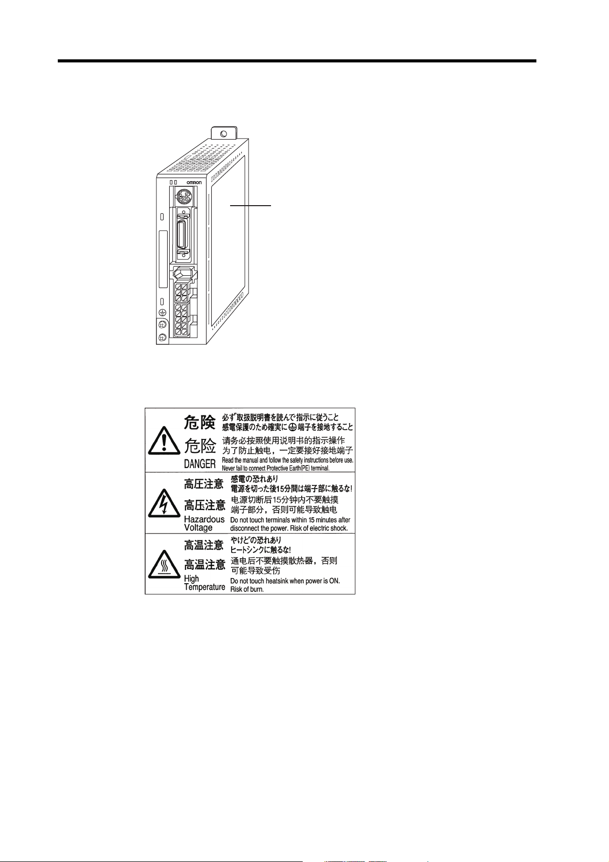
Warning Label Position
Warning labels are located on the product as shown in the following illustration.
Be sure to follow the instructions given there.
PWR
ALM
C
N
3
C
N
1
C
N
2
C
N
B
C
N
A
Warning label
(Example of R7D-BP01H)
Warning Label Contents
Disposing of the Product
Dispose of the product as industrial waste.
10
Page 13
Items to Check When Unpacking
Items to Check When Unpacking
Check the following items after removing the product from the package.
Has the correct product been delivered?
Has the product been damaged in shipping?
Accessories Provided with Product
Safety Precautions document × 1
No connectors or mounting screws are provided. They have to be prepared by the user.
Should you find any problems (missing parts, damage to the Servo Drive, etc.), please contact
your local sales representative or OMRON sales office.
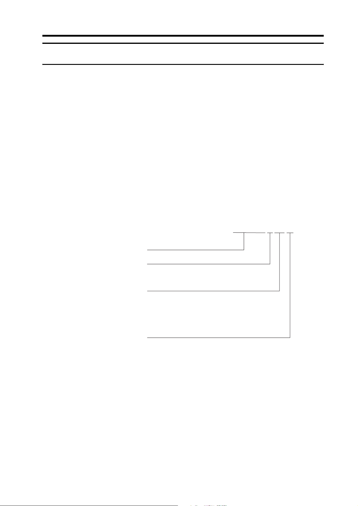
Understanding Model Numbers
Servo Drive Models
The model number provides information such as the Servo Drive type, the applicable
Servomotor capacity, and the power supply voltage.
SMARTSTEP 2
Servo Drive
Drive Type
P: Pulse-string input type
Applicable Servomotor
Capacity
A5: 50 W
01: 100 W
02: 200 W
04: 400 W
Power Supply Voltage
L: 100 VAC
H: Single/Three-phase 200 VAC
HH: Single-phase 200 VAC
Note Single phase: Haploid phase
R7D-BP01H
11
Page 14
Items to Check When Unpacking
Servomotor Models
The model number provides information such as the Servomotor type, Servomotor capacity, rated
rotation speed, and options.
G-Series Servomotor
Motor Type
None: Cylinder type
P: Flat type
Servomotor Capacity
050: 50 W
100: 100 W
200: 200 W
400: 400 W
Rated Rotation Speed
30: 3000 r/min
R88M-GP10030H-BOS2
Power Supply Voltage
H: 200 VAC
L: 100 VAC
Options
None: Straight shaft
B: With brake
O: With oil seal
S2: With key and tap
12
Page 15

About this Manual
This manual consists of the following chapters. Refer to this table and choose the required chapters
of the manual.
About this Manual
Overview
Chapter 1
Chapter 2
Chapter 3 Specifications
Chapter 4 System Design
Chapter 5 Operating Functions
Chapter 6 Operation
Chapter 7 Adjustment Functions
Chapter 8 Troubleshooting
Appendix
Features and System
Configuration
Standard Models and
Dimensions
Connection Examples
Describes the features and names of parts of the product as well
as the EC Directives and the UL standards.
Provides the model numbers, external and mounted dimensions
for Servo Drives, Servomotors, Decelerators, and peripheral devices.
Provides the general specifications, performance specifications,
connector specifications, and I/O circuit specifications for Servo
Drives and the general specifications and performance specifications for Servomotors, as well as specifications for accessories
such as encoders.
Describes the installation conditions for Servo Drives, Servomotors, and Decelerators, EMC conforming wiring methods, calculations of regenerative energy, and performance information on the
External Regeneration Resistor.
Describes the electronic gear function and other operating functions as well as the parameter setting procedure.
Describes operating procedures and how to use the Parameter
Unit.
Describes realtime autotuning function, manual tuning and other
procedures for gain adjustment.
Describes items to check for troubleshooting, error diagnoses using alarm displays and the countermeasures, error diagnoses
based on the operation status and the countermeasures, and periodic maintenance.
Provides examples of connection with OMRON PLCs and Position
Controllers.
13
Page 16

CONTENTS
Introduction .................................................................................. 1
Precautions for Safe Use............................................................. 5
Items to Check When Unpacking ................................................ 11
About this Manual ........................................................................ 13
Chapter 1 Features and System Configuration
1-1 Overview ................................................................................................. 1-1
1-2 System Configuration.............................................................................. 1-2
1-3 Names of Parts and Functions................................................................ 1-3
1-4 System Block Diagrams .......................................................................... 1-5
1-5 Applicable Standards .............................................................................. 1-6
Chapter 2 Standard Models and Dimensions
2-1 Standard Models ..................................................................................... 2-1
2-2 External and Mounted Dimensions ......................................................... 2-13
Chapter 3 Specifications
3-1 Servo Drive Specifications ...................................................................... 3-1
3-2 Servomotor Specifications ...................................................................... 3-16
3-3 Decelerator Specifications ...................................................................... 3-26
3-4 Cable and Connector Specifications ....................................................... 3-30
3-5 Servo Relay Units and Cable Specifications........................................... 3-53
3-6 Parameter Unit Specifications................................................................. 3-78
3-7 External Regeneration Resistors Specifications ..................................... 3-79
3-8 Reactor Specifications ............................................................................ 3-80
Chapter 4 System Design
4-1 Installation Conditions ............................................................................. 4-1
4-2 Wiring ...................................................................................................... 4-10
4-3 Wiring Conforming to EMC Directives..................................................... 4-18
4-4 Regenerative Energy Absorption ............................................................ 4-33
Chapter 5 Operating Functions
5-1 Position Control....................................................................................... 5-1
5-2 Internally Set Speed Control ................................................................... 5-4
5-3 Forward and Reverse Drive Prohibit ....................................................... 5-7
5-4 Encoder Dividing ..................................................................................... 5-8
5-5 Electronic Gear ....................................................................................... 5-9
5-6 Brake Interlock ........................................................................................ 5-11
5-7 Gain Switching ........................................................................................ 5-13
5-8 Torque Limit ............................................................................................ 5-15
5-9 Overrun Limit........................................................................................... 5-16
5-10 User Parameters ..................................................................................... 5-17
14
Page 17

CONTENTS
Chapter 6 Operation
6-1 Operational Procedure.............................................................................6-1
6-2 Preparing for Operation ...........................................................................6-2
6-3 Using the Parameter Unit ........................................................................ 6-4
6-4 Trial Operation .........................................................................................6-23
Chapter 7 Adjustment Functions
7-1 Gain Adjustment ......................................................................................7-1
7-2 Realtime Autotuning ................................................................................7-3
7-3 Autotuning................................................................................................7-8
7-4 Disabling the Automatic Gain Adjustment Function.................................7-13
7-5 Manual Tuning .........................................................................................7-15
Chapter 8 Troubleshooting
8-1 Error Processing ......................................................................................8-1
8-2 Alarm Table .............................................................................................8-3
8-3 Troubleshooting .......................................................................................8-5
8-4 Overload Characteristics (Electronic Thermal Function) .........................8-16
8-5 Periodic Maintenance ..............................................................................8-17
15
Page 18

Page 19

Chapter 1
Features and System
Configuration
1-1 Overview .............................................................1-1
Overview of the SMARTSTEP 2 Series...................................1-1
Features of the SMARTSTEP 2 Series.................................... 1-1
1-2 System Configuration........................................1-2
1-3 Names of Parts and Functions .........................1-3
Servo Drive Part Names .......................................................... 1-3
Servo Drive Functions.............................................................. 1-4
1-4 System Block Diagrams .................................... 1-5
1-5 Applicable Standards ........................................1-6
EC Directives ........................................................................... 1-6
UL/cUL Standards.................................................................... 1-6
Page 20

1-1 Overview
1Features and System Con figuration
1
Features and System Configuration
1-1 Overview
Overview of the SMARTSTEP 2 Series
The SMARTSTEP 2 Series is a series of pulse-string input type Servo Drives for position controlling
and it has been designed to function for low-capacity positioning systems. In spite of the compact
size, the SMARTSTEP 2 Series features realtime autotuning and adaptive filter functions that
automatically perform complicated gain adjustments. A notch filter can also be automatically set to
suppress machine vibration by reducing mechanical resonance during operation. The damping
control function of the SMARTSTEP 2 Series realizes stable stopping performance in a mechanism
which vibrates because of the low rigidity of the load.
Features of the SMARTSTEP 2 Series
The SMARTSTEP 2 Series has the following features.
Compact AC Servo Drives
Compared to the SMARTSTEP A Series, the SMARTSTEP 2 Series can reduce the installation
space by 48% and the installation size by 39% in terms of volume. The AC Servo Drives of the
SMARTSTEP 2 Series are equipped with newly developed functions for applications requiring more
precise positioning.
Suppressing Vibration of Low-rigidity Mechanisms during Acceleration/
Deceleration
The damping control function can suppress vibration of low-rigidity mechanisms or devices whose
ends tend to vibrate.
High-speed Positioning via Resonance Suppression Control
The realtime autotuning function automatically estimates the load inertia of the machine in realtime
and sets the optimal gain. The adaptive filter automatically suppresses vibration caused by
resonance.
Compatible with Command Pulse of 90° Phase Difference Inputs
In addition to conventional CW/CCW inputs (2 pulse inputs) and SIGN/PULS inputs (1 pulse input),
the SMARTSTEP 2 supports 90° phase difference inputs. This makes it possible to input encoder
output signals directly into the Servo Drive for simplified synchronization control.
A Wide Range of Pulse Setting Functions
A wide range of pulse setting functions, such as the command pulse multiplying, electronic gear,
and encoder dividing, enable you to perform pulse settings suitable for your device or system.
Simplified Speed Control with Internal Speed Settings
Four internal speed settings allow the speed to be easily switched by using external signals.
Encoder Dividing Output Function
The number of motor encoder pulses output by the Servo Drive can be freely set in the range of 1
to 2,500 pulses per rotation. A parameter can also be set to change the phase.
1-1
Page 21
1-2 System Configuration
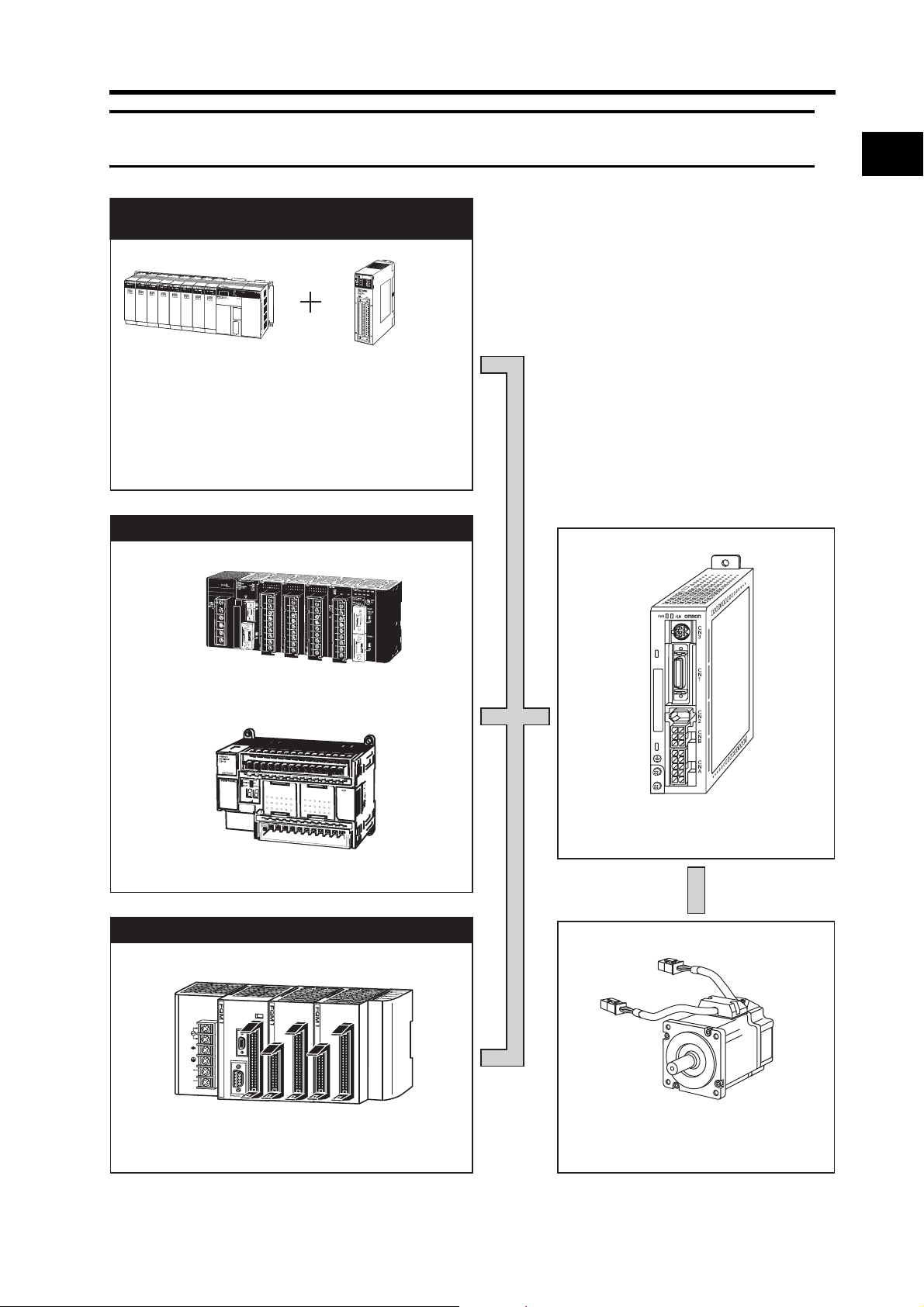
1-2 System Configuration
SYSMAC PLC + Position Control
Unit with pulse-string output
Pulse string
SYSMAC
CJ1/CS1/C-Series
Programmable Controller
SYSMAC PLC with pulse output functions
Position Control Unit
CJ1W-NC113/213/413
CJ1W-NC133/233/433
CS1W-NC113/213/413
CS1W-NC133/233/433
C200HW-NC113/213/413
1
Features and System Configuration
SYSMAC CJ1M
SYSMAC CP1H/CP1L
Flexible Motion Controller with Pulse I/O
L1
AC100
-240V
INPUT
L2/N
NC
NC
FQM1-MMP22
SMARTSTEP 2 Servo Drive
R7D-BP@
OMNUC G-Series Servomotor
R88M-G@/-GP@
1-2
Page 22
1-3 Names of Parts and Functions
1
Features and System Configuration
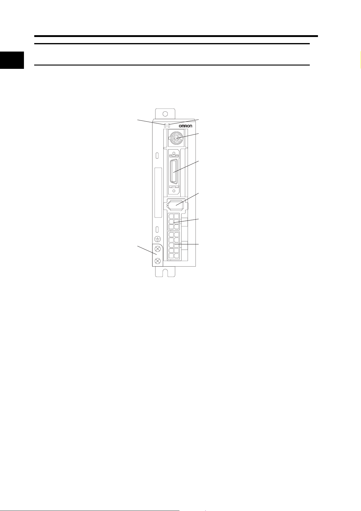
1-3 Names of Parts and Functions
Servo Drive Part Names
Alarm LED indicator (ALM)Power supply LED indicator
Communications connector (CN3)
C
N
3
Control I/O connector (CN1)
C
N
1
Encoder input connector (CN2)
C
N
2
C
Motor connector (CNB)
N
B
C
Main circuit connector (CNA)
N
A
FG terminals for
power supply and
Servomotor power
PWR
ALM
1-3
Page 23
Servo Drive Functions
1-3 Names of Parts and Functions
Power Supply LED Indicator (PWR)
LED Indicator Status
Lit green Main power is ON.
Flashing orange at
1-second intervals
Lit red An alarm has occurred.
A warning has occurred (i.e., an overload, excessive
regenerative energy, or fan speed error).
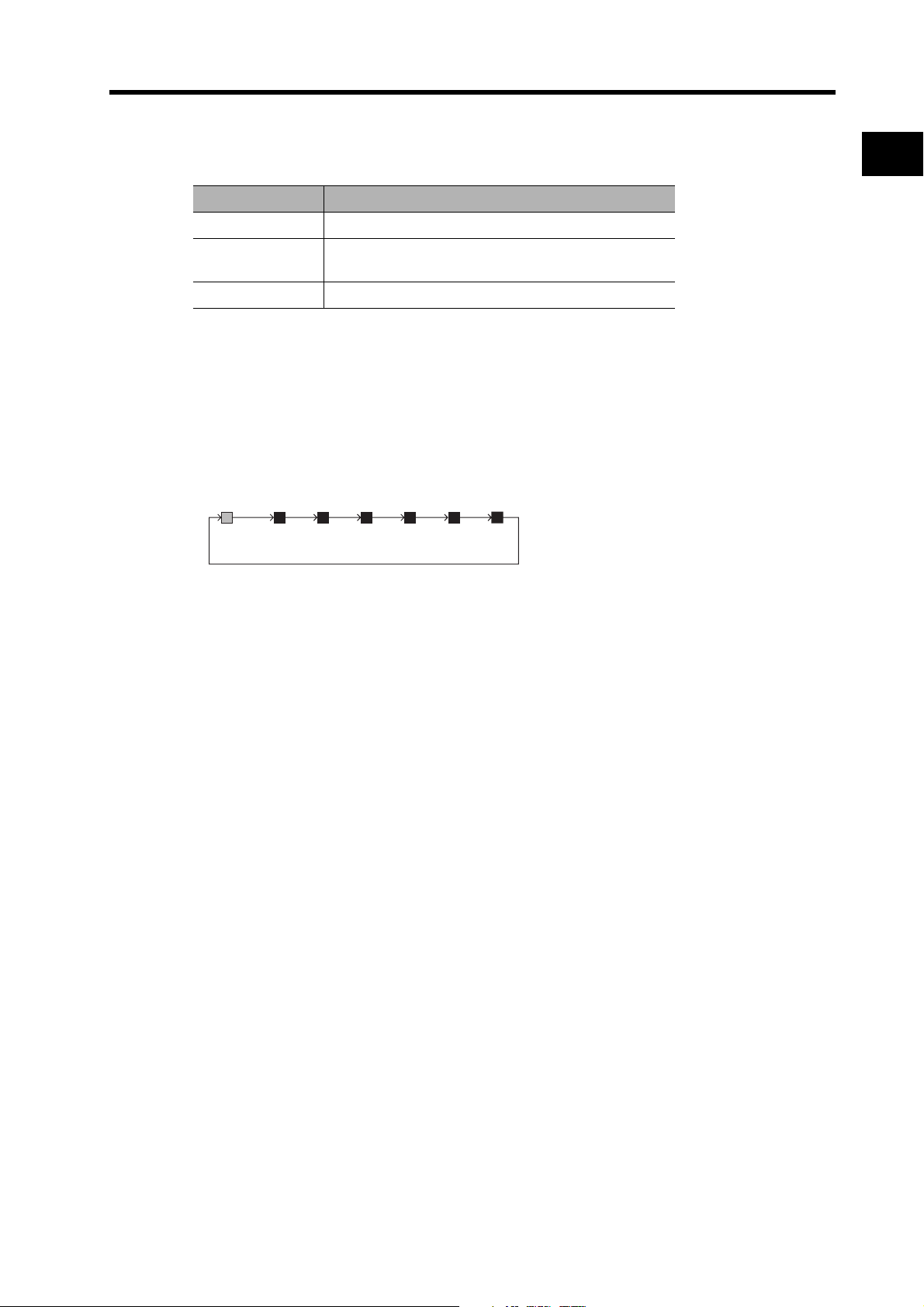
Alarm LED Indicator (ALM)
This indicator is lit when an alarm has occurred. The number of orange and red flashes indicate the
alarm code. For details on the alarm code, refer to Alarm List on page 8-4.
Example:
When an overload alarm (alarm code 16) has occurred and the Unit has stopped
the indicator will flash 1 time in orange and 6 times in red.
Orange: 10s digit, Red: 1s digit
0.5 s1 s
0.5 s 0.5 s 0.5 s 0.5 s
Orange
1 s
Red
0.5 s
Red
0.5 s
Red
0.5 s
0.5 s
Red
Red
0.5 s
Red
0.5 s
1
2 s later
Features and System Configuration
1-4
Page 24
1-4 System Block Diagrams
1
Features and System Configuration
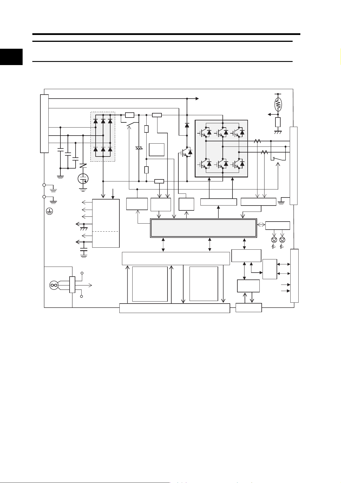
1-4 System Block Diagrams
GR
B1
L1
L2
L3
P
Voltage
detection
N
P
15 V
VCC1
VCC2
SW power supply
Main circuit control
Relay
drive
Overcurrent
detection
Regenerative
control
G1
Position, speed, and torque processor
+VCC
G2
Control power
supply
Control I/O photo isolation
FAN
5 V
Fan
alarm
G
Input signals
1.CW/CCW
2.ECRST
3.RUN 4.RESET
5.POT 6.NOT
7.GSEL/GESEL
CN1 control I/O connector
P
MPU & ASIC
Output signals
.Phases A, B, Z
1
2.INP
3.BKIR
4.ALM
5.WARN
Gate drive
Current detection
Photo
isolation
RS-232C
I/F
CN3 connector
VCC
OH
G1
Display circuit
RS485
I/F
+VCC
1
U
V
W
E
CN2 encoder signal connector
+S
−S
G
1-5
Page 25
1-5 Applicable Standards
1-5 Applicable Standards
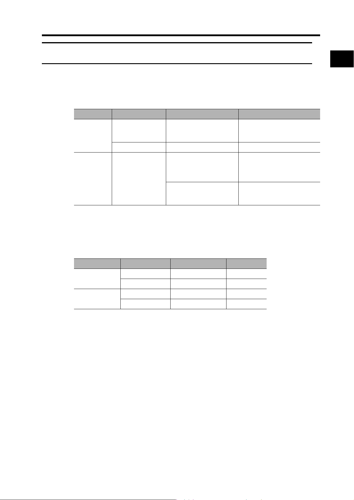
EC Directives
EC Directive Product Applicable standards Comments
Low Voltage
Directive
EMC
Directive
Note To conform to the EMC Directives, the Servomotor and Servo Drive must be installed under
the conditions described in 4-3 Wiring Conforming to EMC Directives.
AC Servo Drive EN 50178 Safety requirements for elec-
AC Servomotor IEC 60034-1 Rotating electric machines
AC Servo Drive and
AC Servomotor
EN 55011 class A
group1
EN 61000-6-2 Electromagnetic compatibility
1
tronic equipment for measure-
ment, control, or laboratory use
Radio disturbance limits and
measurement methods of in-
dustrial, scientific, and medical
radio-frequency equipment
(EMC): Immunity standard for
industrial environments
Features and System Configuration
UL/cUL Standards
Standard Product Applicable standards File number
UL Standard AC Servo Drive UL 508C E179149
CSA standard AC Servo Drive CSA22.2 No. 14 E179149
AC Servomotor UL1004-1 E331224
AC Servomotor CSA22.2 No. 100 E331224
1-6
Page 26

Page 27

Chapter 2
Standard Models and
Dimensions
2-1 Standard Models ................................................ 2-1
Servo Drives ............................................................................2-1
Servomotors............................................................................. 2-1
Parameter Unit.........................................................................2-2
Servo Drive-Servomotor Combinations ...................................2-2
Decelerators............................................................................. 2-4
Accessories and Cables ..........................................................2-8
2-2 External and Mounted Dimensions ................ 2-13
Servo Drives ..........................................................................2-13
Servomotors........................................................................... 2-15
Parameter Unit Dimensions ................................................... 2-18
Decelerator Dimensions......................................................... 2-19
External Regeneration Resistor Dimensions ......................... 2-27
Reactor Dimensions............................................................... 2-28
DIN Rail Mounting Unit Dimensions....................................... 2-29
Page 28
2-1 Standard Models
2Standard Models and Dimensions
2-1 Standard Models
2
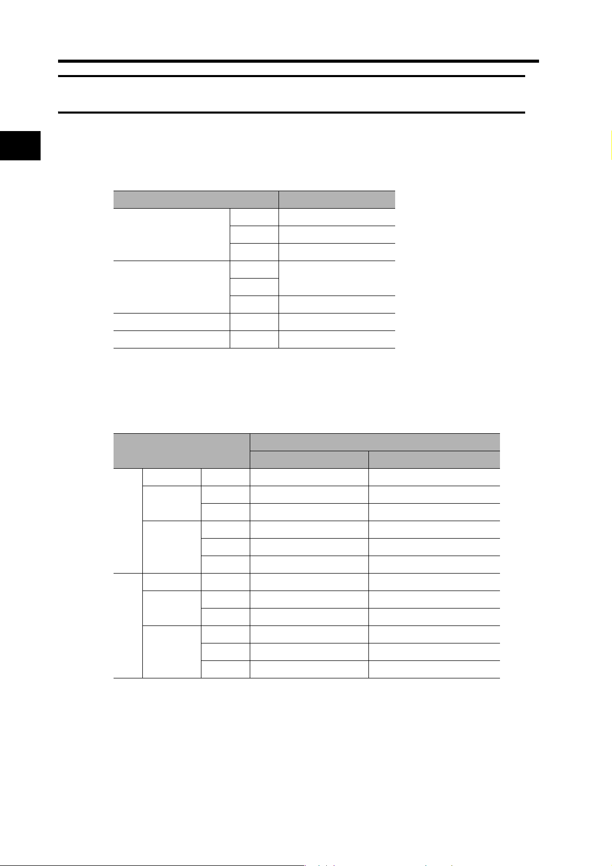
Servo Drives
Specifications Model
Single-phase 100 VAC 50 W R7D-BPA5L
100 W R7D-BP01L
200 W R7D-BP02L
Single-phase/three-phase
200 VAC
Single-phase 200 VAC 200 W R7D-BP02HH
Three-phase 200 VAC 200 W R7D-BP02H
50 W
R7D-BP01H
100 W
400 W R7D-BP04H
Servomotors
Standard Models and Dimensions
3,000-r/min Servomotors
Specifications
100/200 V 50 W R88M-G05030H R88M-G05030H-S2
100 V 100 W R88M-G10030L R88M-G10030L-S2
200 W R88M-G20030L R88M-G20030L-S2
200 V 100 W R88M-G10030H R88M-G10030H-S2
Without brake
100/200 V 50 W R88M-G05030H-B R88M-G05030H-BS2
100 V 100 W R88M-G10030L-B R88M-G10030L-BS2
200 V 100 W R88M-G10030H-B R88M-G10030H-BS2
With brake
200 W R88M-G20030H R88M-G20030H-S2
400 W R88M-G40030H R88M-G40030H-S2
200 W R88M-G20030L-B R88M-G20030L-BS2
200 W R88M-G20030H-B R88M-G20030H-BS2
400 W R88M-G40030H-B R88M-G40030H-BS2
Model
Straight shaft Straight shaft with key and tap
2-1
Note Models with oil seals are also available.
Page 29
3,000-r/min Flat Servomotors
2-1 Standard Models
Specifications
100 V 100W R88M-GP10030L R88M-GP10030L-S2
200 V 100W R88M-GP10030H R88M-GP10030H-S2
Without brake
100 V 100W R88M-GP10030L-B R88M-GP10030L-BS2
200 V 100W R88M-GP10030H-B R88M-GP10030H-BS2
With brake
Note Models with oil seals are also available.
Parameter Unit
Model
Straight shaft Straight shaft with key and tap
200W R88M-GP20030L R88M-GP20030L-S2
200W R88M-GP20030H R88M-GP20030H-S2
400W R88M-GP40030H R88M-GP40030H-S2
200W R88M-GP20030L-B R88M-GP20030L-BS2
200W R88M-GP20030H-B R88M-GP20030H-BS2
400W R88M-GP40030H-B R88M-GP40030H-BS2
Specifications Model
2
Parameter Unit R88A-PR02G
Servo Drive-Servomotor Combinations
Only the Servomotor and Servo Drive combinations listed here can be used. Do not use
other combinations.
Single-phase 100-VAC Combinations
3,000-r/min Servomotors
Rated
output
50 W R7D-BPA5L R88M-G05030H-@ R88M-G05030H-B@
100 W R7D-BP01L R88M-G10030L-@ R88M-G10030L-B@
200 W R7D-BP02L R88M-G20030L-@ R88M-G20030L-B@
3,000-r/min Flat Servomotors
Rated
output
100 W R7D-BP01L R88M-GP10030L-@ R88M-GP10030L-B@
200 W R7D-BP02L R88M-GP20030L-@ R88M-GP20030L-B@
Servo Drive Servomotor
Pulse-string input Without brake With brake
Servo Drive Servomotor
Pulse-string input Without brake With brake
Standard Models and Dimensions
2-2
Page 30
2-1 Standard Models
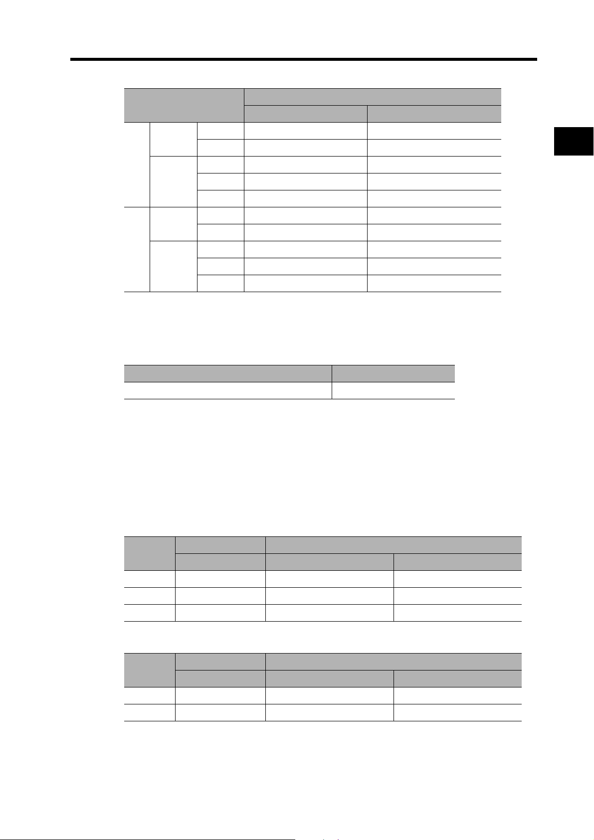
Single-phase 200-VAC Combinations
3,000-r/min Servomotors
Rated
output
2
50 W
100 W R88M-G10030H-@ R88M-G10030H-B@
200 W R7D-BP02HH R88M-G20030H-@ R88M-G20030H-B@
400 W R7D-BP04H R88M-G40030H-@ R88M-G40030H-B@
Servo Drive Servomotor
Pulse-string input Without brake With brake
R7D-BP01H
3,000-r/min Flat Servomotors
Rated
output
100 W R7D-BP01H R88M-GP10030H-@ R88M-GP10030H-B@
200 W R7D-BP02HH R88M-GP20030H-@ R88M-GP20030H-B@
400 W R7D-BP04H R88M-GP40030H-@ R88M-GP40030H-B@
Servo Drive Servomotor
Pulse-string input Without brake With brake
Three-phase 200-VAC Combinations
Standard Models and Dimensions
3,000-r/min Servomotors
Rated
output
Servo Drive Servomotor
Pulse-string input Without brake With brake
R88M-G05030H-@ R88M-G05030H-B@
50 W
100 W R88M-G10030H-@ R88M-G10030H-B@
200 W R7D-BP02H R88M-G20030H-@ R88M-G20030H-B@
400 W R7D-BP04H R88M-G40030H-@ R88M-G40030H-B@
R7D-BP01H
3,000-r/min Flat Servomotors
Rated
output
100 W R7D-BP01H R88M-GP10030H-@ R88M-GP10030H-B@
200 W R7D-BP02H R88M-GP20030H-@ R88M-GP20030H-B@
400 W R7D-BP04H R88M-GP40030H-@ R88M-GP40030H-B@
Servo Drive Servomotor
Pulse-string input Without brake With brake
R88M-G05030H-@ R88M-G05030H-B@
2-3
Page 31
Decelerators
Backlash = 3’ Max.
2-1 Standard Models
Decelerators for Cylindrical Servomotors
Specifications
Motor capacity Gear ratio
1/5 R88G-HPG11B05100B@
1/9 R88G-HPG11B09050B@
50 W
100 W
200 W
1/21 R88G-HPG14A21100B@
1/33 R88G-HPG14A33050B@
1/45 R88G-HPG14A45050B@
1/5 R88G-HPG11B05100B@
1/11 R88G-HPG14A11100B@
1/21 R88G-HPG14A21100B@
1/33 R88G-HPG20A33100B@
1/45 R88G-HPG20A45100B@
1/5 R88G-HPG14A05200B@
1/11 R88G-HPG14A11200B@
1/21 R88G-HPG20A21200B@
1/33 R88G-HPG20A33200B@
1/45 R88G-HPG20A45200B@
1/5 R88G-HPG14A50400B@
Model
2
Standard Models and Dimensions
1/11 R88G-HPG20A11400B@
400 W
Note 1. The standard models have a straight shaft.
Note 2. A model with a key and tap is indicated by adding “J” to the end of the model number (the
suffix shown in the box).
Example: R88G-HPG11B05100BJ
1/21 R88G-HPG20A21400B@
1/33 R88G-HPG32A33400B@
1/45 R88G-HPG32A45400B@
2-4
Page 32

2-1 Standard Models
Decelerator for Flat Servomotors
Specifications
Motor capacity Gear ratio
1/5 R88G-HPG11B05100PB@
2
100 W
200 W
400 W
1/11 R88G-HPG14A11100PB@
1/21 R88G-HPG14A21100PB@
1/33 R88G-HPG20A33100PB@
1/45 R88G-HPG20A45100PB@
1/5 R88G-HPG14A05200PB@
1/11 R88G-HPG20A11200PB@
1/21 R88G-HPG20A21200PB@
1/33 R88G-HPG20A33200PB@
1/45 R88G-HPG20A45200PB@
1/5 R88G-HPG20A05400PB@
1/11 R88G-HPG20A11400PB@
1/21 R88G-HPG20A21400PB@
1/33 R88G-HPG32A33400PB@
1/45 R88G-HPG32A45400PB@
Model
Note 1. The standard models have a straight shaft.
Standard Models and Dimensions
Note 2. A model with a key and tap is indicated by adding “J” to the end of the model number (the
suffix shown in the box).
Example: R88G-HPG11B05100PBJ
2-5
Page 33

Backlash = 15’ Max.
Decelerators for Cylindrical Servomotors
2-1 Standard Models
Specifications
Motor capacity Gear ratio
1/5 R88G-VRSF05B100CJ
1/9 R88G-VRSF09B100CJ
50 W
1/15 R88G-VRSF15B100CJ
1/25 R88G-VRSF25B100CJ
1/5 R88G-VRSF05B100CJ
1/9 R88G-VRSF09B100CJ
100 W
1/15 R88G-VRSF15B100CJ
1/25 R88G-VRSF25B100CJ
1/5 R88G-VRSF05B200CJ
1/9 R88G-VRSF09C200CJ
200 W
1/15 R88G-VRSF15C200CJ
1/25 R88G-VRSF25C200CJ
1/5 R88G-VRSF05C400CJ
1/9 R88G-VRSF09C400CJ
400 W
1/15 R88G-VRSF15C400CJ
1/25 R88G-VRSF25C400CJ
Model
2
Standard Models and Dimensions
Note 1. The standard models have a straight shaft with a key.
Note 2. The backlash is the value when a load of ±5% of the allowable output torque is applied to
the output shaft.
2-6
Page 34

2-1 Standard Models
Decelerators for Flat Servomotors
Specifications
Motor capacity Gear ratio
1/5 R88G-VRSF05B100PCJ
2
100 W
200 W
400 W
Note 1. The standard models have a straight shaft with a key.
Note 2. The backlash is the value when a load of ±5% of the allowable output torque is applied to
the output shaft.
1/9 R88G-VRSF09B100PCJ
1/15 R88G-VRSF15B100PCJ
1/25 R88G-VRSF25B100PCJ
1/5 R88G-VRSF05B200PCJ
1/9 R88G-VRSF09C200PCJ
1/15 R88G-VRSF15C200PCJ
1/25 R88G-VRSF25C200PCJ
1/5 R88G-VRSF05C400PCJ
1/9 R88G-VRSF09C400PCJ
1/15 R88G-VRSF15C400PCJ
1/25 R88G-VRSF25C400PCJ
Model
Standard Models and Dimensions
2-7
Page 35

Accessories and Cables
Encoder Cables (for CN2)
Standard Cables (connectors attached) 3 m R88A-CRGB003C
Robot Cables (connectors attached) 3 m R88A-CRGB003CR
2-1 Standard Models
Specifications Model
2
5 m R88A-CRGB005C
10 m R88A-CRGB010C
15 m R88A-CRGB015C
20 m R88A-CRGB020C
5 m R88A-CRGB005CR
10 m R88A-CRGB010CR
15 m R88A-CRGB015CR
20 m R88A-CRGB020CR
Servomotor Power Cables (for CNB)
Specifications Model
Standard Cables (connectors attached) 3 m R7A-CAB003S
Robot Cables (connectors attached) 3 m R7A-CAB003SR
Brake Cables
Specifications Model
Standard Cables 3 m R88A-CAGA003B
5 m R7A-CAB005S
10 m R7A-CAB010S
15 m R7A-CAB015S
20 m R7A-CAB020S
5 m R7A-CAB005SR
10 m R7A-CAB010SR
15 m R7A-CAB015SR
20 m R7A-CAB020SR
5 m R88A-CAGA005B
10 m R88A-CAGA010B
15 m R88A-CAGA015B
Standard Models and Dimensions
20 m R88A-CAGA020B
Robot Cables 3 m R88A-CAGA003BR
5 m R88A-CAGA005BR
10 m R88A-CAGA010BR
15 m R88A-CAGA015BR
20 m R88A-CAGA020BR
2-8
Page 36

2-1 Standard Models
Power Supply Cables
Specifications Model
Power Supply Input Cable for Single-Phase Power (connectors
attached)
2
Power Supply Input Cable for Three-Phase Power (connectors
attached)
External Regeneration Resistor Connection Cable 2 m R7A-CLB002RG
Personal Computer Monitor Cable
Personal Computer Monitor Cable 2 m R88A-CCG002P2
Connectors
Main Circuit Connector (CNA) R7A-CNB01P
Servomotor Connector (CNB) R7A-CNB01A
Control I/O Connector (CN1) R88A-CNW01C
Encoder Input Connector (CN2) R88A-CNW01R
Servomotor Connector for Encoder Cable R88A-CNG02R
Servomotor Connector for Servomotor Power Cable R88A-CNG01A
Brake Cable Connector R88A-CNG01B
Standard Models and Dimensions
2 m R7A-CLB002S2
2 m R7A-CLB002S3
Specifications Model
Specifications Model
2-9
Page 37

Servo Relay Units (for CN1)
Specifications Model
For CJ1W-NC133/-NC113
For CS1W-NC133/-NC113
For C200HW-NC113
For CJ1W-NC233/-NC433/-NC213/-NC413
For CS1W-NC233/-NC433/-NC213/-NC413
For C200HW-NC213/-NC413
Servo Relay Units
For CJ1M-CPU21
For CJ1M-CPU22
For CJ1M-CPU23
For FQM1-MMP22 XW2B-80J7-12A
For CQM1H-PLB21
For CQM1-CPU43-V1
Servo Relay Unit Cables for Servo Drives
Specifications Model
For Position Control Unit/CQM1
(XW2B-@J6-@B)
Servo Drive
Cables
For CJ1M
(XW2B-20J6-8A/XW2B-40J6-9A)
For FQM1-MMP22
(XW2B-80J7-12A)
2-1 Standard Models
XW2B-20J6-1B
2
XW2B-40J6-2B
XW2B-20J6-8A
XW2B-40J6-9A
(for 2 axes)
XW2B-20J6-3B
1 m XW2Z-100J-B29
2 m XW2Z-200J-B29
1 m XW2Z-100J-B32
2 m XW2Z-200J-B32
1 m XW2Z-100J-B30
2 m XW2Z-200J-B30
Standard Models and Dimensions
2-10
Page 38

2-1 Standard Models
Servo Relay Unit Cables for Position Control Units
Specifications Model
For CJ1W-NC133
2
For CJ1W-NC233/-NC433
For CS1W-NC133
For CS1W-NC233/-NC433
For CJ1W-NC113
For CJ1W-NC213/-NC413
Position Control
Unit Cables
Standard Models and Dimensions
For CS1W-NC113
For C200HW-NC113
For CS1W-NC213/-NC413
For C200HW-NC213/-NC413
For CJ1M-CPU21
For CJ1M-CPU22
For CJ1M-CPU23
For FQM1-MMP22
General-purpose
I/O Cables
0.5 m XW2Z-050J-A18
1 m XW2Z-100J-A18
0.5 m XW2Z-050J-A19
1 m XW2Z-100J-A19
0.5 m XW2Z-050J-A10
1 m XW2Z-100J-A10
0.5 m XW2Z-050J-A11
1 m XW2Z-100J-A11
0.5 m XW2Z-050J-A14
1 m XW2Z-100J-A14
0.5 m XW2Z-050J-A15
1 m XW2Z-100J-A15
0.5 m XW2Z-050J-A6
1 m XW2Z-100J-A6
0.5 m XW2Z-050J-A7
1 m XW2Z-100J-A7
0.5 m XW2Z-050J-A33
1 m XW2Z-100J-A33
0.5 m XW2Z-050J-A28
1 m XW2Z-100J-A28
2 m XW2Z-200J-A28
0.5 m XW2Z-050J-A30
Control Cables (for CN1)
Connector-Terminal Block Cables 1 m XW2Z-100J-B28
General-purpose Control Cables 1 m R7A-CPB001S
Special I/O Cables
For CQM1H-PLB21
For CQM1-CPU43-V1
Specifications Model
1 m XW2Z-100J-A30
2 m XW2Z-200J-A30
0.5 m XW2Z-050J-A3
1 m XW2Z-100J-A3
2 m XW2Z-200J-B28
2 m R7A-CPB002S
2-11
Page 39

Connector-Terminal Block Conversion Units
Specifications Model
M3 screws type XW2B-34G4
M3.5 screws type XW2B-34G5
M3 screws type XW2D-34G6
External Regeneration Resistors
Specifications Model
Regeneration capacity: 70 W, 47 Ω R88A-RR22047S
Regeneration capacity: 20 W, 100 Ω R88A-RR080100S
Regeneration capacity: 20 W, 50 Ω R88A-RR08050S
Reactors
Specifications Applicable Servo Drive Model
R7D-BPA5L 3G3AX-DL2002
Single-phase 100 V
R7D-BP01L 3G3AX-DL2004
R7D-BP02L 3G3AX-DL2007
2-1 Standard Models
2
Single-phase 200 V
Three-phase 200 V
DIN Rail Mounting Unit
DIN Rail Mounting Unit R7A-DIN01B
R7D-BP01H 3G3AX-DL2004
R7D-BP02HH 3G3AX-DL2004
R7D-BP04H 3G3AX-DL2007
R7D-BP01H 3G3AX-AL2025
R7D-BP02H 3G3AX-AL2025
R7D-BP04H 3G3AX-AL2025
Specifications Model
Standard Models and Dimensions
2-12
Page 40

2-2 External and Mounted Dimensions
2-2 External and Mounted Dimensions
2
Servo Drives
R7D-BPA5L/-BP01L/-BP01H/-BP02H (50 W/100 W/200 W)
35
15
20
5
5
130
120
Standard Models and Dimensions
140
5.2 dia.
ALMPWR
5.2
C
N
3
C
N
1
C
N
2
C
N
B
C
N
A
70
5.1
105
Mounting Hole
Dimensions
Two, M4
140
130±0.5 55
15 20
2-13
Page 41

2-2 External and Mounted Dimensions
R7D-BP02L/-BP02HH/-BP04H (200 W/400 W)
40
15
20
5
140
5
130
120
5.2 dia.
ALMPWR
C
N
3
C
N
1
C
N
2
C
N
B
Mounting Hole
Dimensions
Two, M4
55
140
130±0.5
2
5.2
C
N
A
5.1
70
105
15 25
Standard Models and Dimensions
2-14
Page 42

2-2 External and Mounted Dimensions
Servomotors
3,000-r/min 50-/100-W Servomotors
2
Standard Models and Dimensions
/-G05030H-B(S2)/-G10030L-B(S2)/-G10030H-B(S2)
Encoder
Connector
LL 25
230
R88M-G05030H 72 26.5
R88M-G05030H-B
R88M-G10030@
R88M-G10030@-B
Brake Connector
Motor Connector
200
LN
Model
*1
*2
*1, *2
R88M-G05030H(-S2)/-G10030L(-S2)/-G10030H(-S2)
36
8 dia., height: 6
LL LN
(mm) (mm)
102 26.5
92 46.5
122 46.5
40 × 40
30 dia., height: 7
32
Two, 4.3 dia.
46 dia.
(Dimensions of shaft end
with key and tap)
12.5
3
3, height: 9
1.8
M3
(depth: 6)
*1. This is the model number for the Servomotor with a brake.
*2. Put “L” or “H” in the place indicated by the box.
Note The standard models have a straight shaft. A model with a key and tap is indicated by
adding “S2” to the end of the model number.
2-15
Page 43

3,000-r/min 200-/400-W Servomotors
R88M-G20030L(-S2)/-G20030H(-S2)/-G40030H(-S2)
/-G20030L-B(S2)/-G20030H-B(S2)/-G40030H-B(S2)
2-2 External and Mounted Dimensions
(Dimensions of shaft end
Brake connector
Encoder
Servomotor connector
connector
LL 30
36.5
220
200
S dia., height: 6
50 dia., height: 7
Model
R88M-G20030@
R88M-G20030@-B
R88M-G40030H 99 14 22.5 5h9 5 3 M5 10
R88M-G40030H-B
*1
*1,*2
*2
LL S
(mm) (mm) (mm) (mm) (mm) (mm)
79.5 11 18 4h9 4 2.5 M4 8
116 11 18 4h9 4 2.5 M4 8
135.5 14 22.5 5h9 5 3 M5 10
with key and tap)
QK
Four,
4.5 dia.
Dimensions for models with key and tap
QK b h t1 M L
60 × 60
43
h
70 dia.
b
t1
M (depth: L)
*3
2
Standard Models and Dimensions
*1. Put “L” or “H” in the place indicated by the box.
*2 .This is the model number for the Servomotor with a brake.
*3. A model with a key and tap is indicated by adding “S2” to the end of the model number.
Note The standard models have a straight shaft.
2-16
Page 44

2-2 External and Mounted Dimensions
3,000-r/min 100-/200-/400-W Flat Servomotors
R88M-GP10030L(-S2)/-GP10030H(-S2)/-GP20030L(-S2)/-GP20030H(-S2)
/-GP40030H(-S2)
R88M-GP10030L-B(S2)/-GP10030H-B(S2)/-GP20030L-B(S2)/-GP20030H-B(S2)
2
Encoder
connector
/-GP40030H-B(S2)
Servomotor connector
LL LR
(7)
220
(7)
FG
200
Standard Models and Dimensions
Model
R88M-GP10030@
R88M-GP10030@-B
R88M-GP20030@
R88M-GP20030@-B
*1
*1, *2
*1
*1, *2
Break connector
S dia., height: 6
LL LR S D1 D2 C F G
(mm) (mm) (mm) (mm) (mm) (mm) (mm) (mm)
60.5 25 8 70 50 60 3 7
84.5 25 8 70 50 60 3 7
67.5 30 11 90 70 80 5 8
1003011907080 5 8
Four,
Z-dia.
KL1
D2 dia., height: 7
C × C
D1 dia.
(Dimensions of shaft end
with key and tap)
QK
h
b
t1
M (depth: L)
R88M-GP40030H 82.5 30 14 90 70 80 5 8
Model
*1
*1
*2
*1,*2
*1,*2
*2
1153014907080 5 8
KL1 Z
Dimensions for models with key and tap
QK b h t1 M L
(mm) (mm) (mm) (mm) (mm) (mm)
43 4.5 12.5 3h9 3 1.8 M3 6
43 4.5 12.5 3h9 3 1.8 M3 6
53 5.5 18 4h9 4 2.5 M4 8
53 5.5 18 4h9 4 2.5 M4 8
53 5.5 22.5 5h9 5 3.0 M5 10
*3
R88M-GP40030H-B
R88M-GP10030@
R88M-GP10030@-B
R88M-GP20030@
R88M-GP20030@-B
R88M-GP40030H 53 5.5 22.5 5h9 5 3.0 M5 10
R88M-GP40030H-B
*1. Put “L” or “H” in the place indicated by the box.
*2. This is the model number for the Servomotor with a brake.
*3. A model with a key and tap is indicated by adding “S2” to the end of the model number.
Note The standard models have a straight shaft.
2-17
Page 45

Parameter Unit Dimensions
R88A-PR02G
2-2 External and Mounted Dimensions
(62)
(1500)
(15)
(114)
Mini DIN 8-pin
MD connector
(24)
M3, depth: 5
(15)
2
Standard Models and Dimensions
2-18
Page 46

2-2 External and Mounted Dimensions
Decelerator Dimensions
Backlash = 3’ Max.
2
Decelerators for Cylindrical Servomotors
Model
(R88G-)
1/5
1/9
50 W
100 W
200 W
Standard Models and Dimensions
400 W
1/21
1/33
1/45
1/5
1/11
1/21
1/33
1/45
1/5
1/11
1/21
1/33
1/45
1/5
1/11
1/21
1/33
1/45
HPG11B05100B@
HPG11B09050B@
HPG14A21100B@
HPG14A33050B@
HPG14A45050B@
HPG11B05100B@
HPG14A11100B@
HPG14A21100B@
HPG20A33100B@
HPG20A45100B@
HPG14A05200B@
HPG14A11200B@
HPG20A21200B@
HPG20A33200B@
HPG20A45200B@
HPG14A05400B@
HPG20A11400B@
HPG20A21400B@
HPG32A33400B@
HPG32A45400B@
Dimensions (mm)
LM LR C1 C2 D1 D2 D3 D4 D5
39.5 42 40 40 × 40 46 46 40.0 39.5 29
39.5 42 40 40 × 40 46 46 40.0 39.5 29
64.0 58 60 60 × 60 70 46 56.0 55.5 40
64.0 58 60 60 × 60 70 46 56.0 55.5 40
64.0 58 60 60 × 60 70 46 56.0 55.5 40
39.5 42 40 40 × 40 46 46 40.0 39.5 29
64.0 58 60 60 × 60 70 46 56.0 55.5 40
64.0 58 60 60 × 60 70 46 56.0 55.5 40
66.5 80 90 55 dia. 105 46 85.0 84.0 59
66.5 80 90 55 dia. 105 46 85.0 84.0 59
64.0 58 60 60 × 60 70 70 56.0 55.5 40
64.0 58 60 60 × 60 70 70 56.0 55.5 40
71.0 80 90 89 dia. 105 70 85.0 84.0 59
71.0 80 90 89 dia. 105 70 85.0 84.0 59
71.0 80 90 89 dia. 105 70 85.0 84.0 59
64.0 58 60 60 × 60 70 70 56.0 55.5 40
71.0 80 90 89 dia. 105 70 85.0 84.0 59
71.0 80 90 89 dia. 105 70 85.0 84.0 59
104.0 133 120 122 dia. 135 70 115.0 114.0 84
104.0 133 120 122 dia. 135 70 115.0 114.0 84
Note 1. The standard models have a straight shaft. A model with a key and tap is indicated by adding “J” to the
end of the model number (the suffix shown in the box).
Note 2. The diameter of the motor shaft insertion hole is the same as the shaft diameter of the corresponding
motors.
Outline Drawings
C1 × C1
D1 dia.
Four, Z1 dia.
D3 dia., height: 7
D4 dia.
D5 dia.
E
S dia., height: 7
T
F1
F2LRG
LM
Set bolt (AT)
Four, Z2
D2 dia.
C2
2-19
Page 47

Dimensions (mm) Key and tap dimensions (mm)
E F1 F2 G S T Z1 Z2 AT
27 2.2 15 5 8 20 3.4 M4 M3
27 2.2 15 5 8 20 3.4 M4 M3
37 2.5 21 8 16 28 5.5 M4 M3
37 2.5 21 8 16 28 5.5 M4 M3
37 2.5 21 8 16 28 5.5 M4 M3
27 2.2 15 5 8 20 3.4 M4 M3
37 2.5 21 8 16 28 5.5 M4 M3
37 2.5 21 8 16 28 5.5 M4 M3
53 7.527102542 9.0M4 M4
53 7.527102542 9.0M4 M4
37 2.5 21 8 16 28 5.5 M4 M3
37 2.5 21 8 16 28 5.5 M4 M3
53 7.527102542 9.0M4 M4
53 7.527102542 9.0M4 M4
53 7.527102542 9.0M4 M4
37 2.5 21 8 16 28 5.5 M4 M3
53 7.527102542 9.0M4 M4
53 7.527102542 9.0M4 M4
98 12.5 35 13 40 82 11.0 M4 M4
98 12.5 35 13 40 82 11.0 M4 M4
*1
2-2 External and Mounted Dimensions
Weight
QK b h t1 M L
15 3 3 1.8 M3 6 0.29
15 3 3 1.8 M3 6 0.29
25553M4 81.04
25553M4 81.04
25553M4 81.04
15 3 3 1.8 M3 6 0.29
25553M4 81.04
25553M4 81.04
36874.0M612 2.4
36874.0M612 2.4
25553M4 81.02
25553M4 81.09
36874.0M612 2.9
36874.0M612 2.9
36874.0M612 2.9
25553M4 81.09
36874.0M612 2.9
36874.0M612 2.9
70 12 8 5.0 M10 20 7.5
70 12 8 5.0 M10 20 7.5
(kg)
2
Standard Models and Dimensions
*1. This is the set bolt.
Key and Tap Dimensions
QK
h
b
t1
M (depth: L)
2-20
Page 48

2-2 External and Mounted Dimensions
Decelerators for Flat Servomotors
Model
(R88G-)
1/5
2
100 W
200 W
400 W
1/11
1/21
1/33
1/45
1/5
1/11
1/21
1/33
1/45
1/5
1/11
1/21
1/33
1/45
HPG11B05100PB@
HPG14A11100PB@
HPG14A21100PB@
HPG20A33100PB@
HPG20A45100PB@
HPG14A05200PB@
HPG20A11200PB@
HPG20A21200PB@
HPG20A33200PB@
HPG20A45200PB@
HPG20A05400PB@
HPG20A11400PB@
HPG20A21400PB@
HPG32A33400PB@
HPG32A45400PB@
LM LR C1 C2 D1 D2 D3 D4 D5
39.5424060 × 60 46 70 40.0 39.5 29
64.0586060 × 60 70 70 56.0 55.5 40
64.0586060 × 60 70 70 56.0 55.5 40
71.0 80 90 89 dia. 105 70 85.0 84.0 59
71.0 80 90 89 dia. 105 70 85.0 84.0 59
65.0586080 × 80 70 90 56.0 55.5 40
78.0809080 × 80 105 90 85.0 84.0 59
78.0809080 × 80 105 90 85.0 84.0 59
78.0809080 × 80 105 90 85.0 84.0 59
78.0809080 × 80 105 90 85.0 84.0 59
78.0809080 × 80 105 90 85.0 84.0 59
78.0809080 × 80 105 90 85.0 84.0 59
78.0809080 × 80 105 90 85.0 84.0 59
104.0 133 120 122 dia. 135 90 115.0 114.0 84
104.0 133 120 122 dia. 135 90 115.0 114.0 84
Dimensions (mm)
Note 1. The standard models have a straight shaft. A model with a key and tap is indicated by adding “J” to the
Standard Models and Dimensions
end of the model number.
Note 2. The diameter of the motor shaft insertion hole is the same as the shaft diameter of the corresponding
motors.
Outline Drawings
C1 × C1
D1 dia.
D4 dia.
D5 dia.
D3 dia., height: 7
Four, Z1 dia.
S dia., height: 7
E
T
F1
F2LRG
LM
Set bolt (AT)
Four, Z2
D2 dia.
C2
2-21
Page 49

2-2 External and Mounted Dimensions
Dimensions (mm) Key and tap dimensions (mm)
E F1 F2 G S T Z1 Z2 AT*1QK b h t1 M L
27 2.2 15 5 8 20 3.4 M4 M3
37 2.5 21 8 16 28 5.5 M4 M3
37 2.5 21 8 16 28 5.5 M4 M3
53 7.527102542 9.0M4 M3
53 7.527102542 9.0M4 M3
37 2.5 21 8 16 28 5.5 M4 M4
53 7.527102542 9.0M5 M4
53 7.527102542 9.0M5 M4
53 7.527102542 9.0M5 M4
53 7.527102542 9.0M5 M4
53 7.527102542 9.0M5 M4
53 7.527102542 9.0M5 M4
53 7.527102542 9.0M5 M4
98 12.5 35 13 40 82 11.0 M5 M6
98 12.5 35 13 40 82 11.0 M5 M6
15 3 3 1.8 M3 6 0.34
25 5 5 3.0 M4 8 1.04
25 5 5 3.0 M4 8 1.04
36 8 7 4.0 M6 12 2.9
36 8 7 4.0 M6 12 2.9
25 5 5 3.0 M4 8 0.99
36 8 7 4.0 M6 12 3.1
36 8 7 4.0 M6 12 3.1
36 8 7 4.0 M6 12 3.1
36 8 7 4.0 M6 12 3.1
36 8 7 4.0 M6 12 3.1
36 8 7 4.0 M6 12 3.1
36 8 7 4.0 M6 12 3.1
70 12 8 5.0 M10 20 7.8
70 12 8 5.0 M10 20 7.8
Weight
(kg)
2
*1. This is the set bolt.
Key and Tap Dimensions
QK
h
b
t1
M (depth: L)
Standard Models and Dimensions
2-22
Page 50

2-2 External and Mounted Dimensions
Backlash = 15’ Max.
Decelerators for Cylindrical Servomotors
Model
2
50 W
100 W
200 W
400 W
Standard Models and Dimensions
(R88G-)
1/5 VRSF05B100CJ
1/9 VRSF09B100CJ
1/15 VRSF15B100CJ
1/25 VRSF25B100CJ
1/5 VRSF05B100CJ
1/9 VRSF09B100CJ
1/15 VRSF15B100CJ
1/25 VRSF25B100CJ
1/5 VRSF05B200CJ
1/9 VRSF09C200CJ
1/15 VRSF15C200CJ
1/25 VRSF25C200CJ
1/5 VRSF05C400CJ
1/9 VRSF09C400CJ
1/15 VRSF15C400CJ
1/25 VRSF25C400CJ
Dimensions (mm)
LM LR C1 C2 D1 D2 D3 D4 E3 F G
67.5 32 40 52 46 60 50 45 10 3 6
67.5 32 40 52 46 60 50 45 10 3 6
78.0 32 40 52 46 60 50 45 10 3 6
78.0 32 40 52 46 60 50 45 10 3 6
67.5 32 40 52 46 60 50 45 10 3 6
67.5 32 40 52 46 60 50 45 10 3 6
78.0 32 40 52 46 60 50 45 10 3 6
78.0 32 40 52 46 60 50 45 10 3 6
72.5 32 60 52 70 60 50 45 10 3 10
89.5 50 60 78 70 90 70 62 17 3 8
100.050607870 90 706217 3 8
100.050607870 90 706217 3 8
89.5 50 60 78 70 90 70 62 17 3 8
89.5 50 60 78 70 90 70 62 17 3 8
100.050607870 90 706217 3 8
100.050607870 90 706217 3 8
Note 1. The standard models have a straight shaft with a key.
Note 2. The diameter of the motor shaft insertion hole is the same as the shaft diameter of the corresponding
motors.
Outline Drawings
E3
D1 dia.
Four, Z1
C1 × C1
F
D4 dia.
S dia., height: 6
G
LM
T
LR
D3 dia., height: 7
Four, Z2 (effective depth: L)
D2 dia.
C2 × C2
2-23
Page 51

2-2 External and Mounted Dimensions
Dimensions (mm) Key dimensions (mm)
S T Z1 Z2 AT
12 20 M4 M5 M3 12 16 4 4 2.5
12 20 M4 M5 M3 12 16 4 4 2.5
12 20 M4 M5 M3 12 16 4 4 2.5
12 20 M4 M5 M3 12 16 4 4 2.5
12 20 M4 M5 M3 12 16 4 4 2.5
12 20 M4 M5 M3 12 16 4 4 2.5
12 20 M4 M5 M3 12 16 4 4 2.5
12 20 M4 M5 M3 12 16 4 4 2.5
12 20 M4 M5 M4 12 16 4 4 2.5
19 30 M4 M6 M4 20 22 6 6 3.5
19 30 M4 M6 M4 20 22 6 6 3.5
19 30 M4 M6 M4 20 22 6 6 3.5
19 30 M4 M6 M4 20 22 6 6 3.5
19 30 M4 M6 M4 20 22 6 6 3.5
19 30 M4 M6 M4 20 22 6 6 3.5
19 30 M4 M6 M4 20 22 6 6 3.5
*1
L QK b h t1
Weight
(kg)
0.55 VRSF05B100CJ 1/5
0.55 VRSF09B100CJ 1/9
0.70 VRSF15B100CJ 1/15
0.70 VRSF25B100CJ 1/25
0.55 VRSF05B100CJ 1/5
0.55 VRSF09B100CJ 1/9
0.70 VRSF15B100CJ 1/15
0.70 VRSF25B100CJ 1/25
0.72 VRSF05B200CJ 1/5
1.70 VRSF09C200CJ 1/9
2.10 VRSF15C200CJ 1/15
2.10 VRSF25C200CJ 1/25
1.70 VRSF05C400CJ 1/5
1.70 VRSF09C400CJ 1/9
2.10 VRSF15C400CJ 1/15
2.10 VRSF25C400CJ 1/25
Model
(R88G-)
2
50 W
100 W
200 W
400 W
Standard Models and Dimensions
*1. This is the set bolt.
Set bolt (AT)
Key Dimensions
QK
b
t1
h
2-24
Page 52

2-2 External and Mounted Dimensions
Decelerators for Flat Servomotors
Model
(R88G-)
1/5 VRSF05B100PCJ
2
100 W
200 W
400 W
1/9 VRSF09B100PCJ
1/15 VRSF15B100PCJ
1/25 VRSF25B100PCJ
1/5 VRSF05B200PCJ
1/9 VRSF09C200PCJ
1/15 VRSF15C200PCJ
1/25 VRSF25C200PCJ
1/5 VRSF05C400PCJ
1/9 VRSF09C400PCJ
1/15 VRSF15C400PCJ
1/25 VRSF25C400PCJ
LM LR C1 C2 D1 D2 D3 D4 E3 F G
67.5 32 60 52 70 60 50 45 10 3 8
67.5 32 60 52 70 60 50 45 10 3 8
78.0 32 60 52 70 60 50 45 10 3 8
78.0 32 60 52 70 60 50 45 10 3 8
72.5 32 80 52 90 60 50 45 10 3 12
89.5 50 80 78 90 90 70 62 17 3 12
100.0 50 80 78 90 90 70 62 17 3 12
100.0 50 80 78 90 90 70 62 17 3 12
89.5 50 80 78 90 90 70 62 17 3 12
89.5 50 80 78 90 90 70 62 17 3 12
100.0 50 80 78 90 90 70 62 17 3 12
100.0 50 80 78 90 90 70 62 17 3 12
Dimensions (mm)
Note 1. The standard models have a straight shaft with a key.
Note 2. The diameter of the motor shaft insertion hole is the same as the shaft diameter of the corresponding
motors.
Outline Drawings
Standard Models and Dimensions
Four, Z1
D1 dia.
C1 × C1
G
LM
E3
F
D4 dia.
S dia., height: 6
T
LR
D3 dia., height: 7
Four, Z2 (effective depth: L)
D2 dia.
C2 × C2
2-25
Page 53

2-2 External and Mounted Dimensions
Dimensions (mm) Key dimensions (mm)
S T Z1 Z2 AT
12 20 M4 M5 M3 12 16 4 4 2.5
12 20 M4 M5 M3 12 16 4 4 2.5
12 20 M4 M5 M3 12 16 4 4 2.5
12 20 M4 M5 M3 12 16 4 4 2.5
12 20 M5 M5 M4 12 16 4 4 2.5
19 30 M5 M6 M4 20 22 6 6 3.5
19 30 M5 M6 M4 20 22 6 6 3.5
19 30 M5 M6 M4 20 22 6 6 3.5
19 30 M5 M6 M4 20 22 6 6 3.5
19 30 M5 M6 M4 20 22 6 6 3.5
19 30 M5 M6 M4 20 22 6 6 3.5
19 30 M5 M6 M4 20 22 6 6 3.5
*1
L QK b h t1
*1. This is the set bolt.
Weight
(kg)
0.72 VRSF05B100PCJ 1/5
0.72 VRSF09B100PCJ 1/9
0.87 VRSF15B100PCJ 1/15
0.87 VRSF25B100PCJ 1/25
0.85 VRSF05B200PCJ 1/5
1.80 VRSF09C200PCJ 1/9
2.20 VRSF15C200PCJ 1/15
2.20 VRSF25C200PCJ 1/25
1.80 VRSF05C400PCJ 1/5
1.80 VRSF09C400PCJ 1/9
2.20 VRSF15C400PCJ 1/15
2.20 VRSF25C400PCJ 1/25
Model
(R88G-)
2
100 W
200 W
400 W
Set bolt (AT)
Key Dimensions
QK
Standard Models and Dimensions
b
t1
h
2-26
Page 54

2-2 External and Mounted Dimensions
External Regeneration Resistor Dimensions
External Regeneration Resistor
2
R88A-RR08050S/R88A-RR080100S
Thermal switch output
)
2
)
2
(0.75 mm
3 dia.
1.5 dia.
(0.3 mm
6
t1.2 104
20
R88A-RR22047S
Standard Models and Dimensions
)
2
1.5 dia.
(0.3 mm
500
Thermal switch output
)
2
3 dia.
(0.75 mm
122
130
4.2
4.2
28
48
43.5
62
6
t1.2 200
20
500
220
230
2-27
Page 55

Reactor Dimensions
3G3AX-DL2002/-DL2004
Ground terminal
(M4)
56
66
2-2 External and Mounted Dimensions
72
90
Two, M4
Four,
5.2 × 8
98
L
2
3G3AX-DL2007
Model
3G3AX-DL2002 85
3G3AX-DL2004 95
Ground terminal
(M4)
Dimension
(mm)
L
56
66
72
90
Two, M4
Four, 5.2 × 8
Standard Models and Dimensions
105
98
2-28
Page 56

2-2 External and Mounted Dimensions
3G3AX-AL2025
Six, M4
terminal screws
2
Ground terminal (M5)
Ro R So S To T
150
50±1
130
Four,
6 dia.
67±1
60 40
67±1
82
Connections
Ro R So S To T
92
DIN Rail Mounting Unit Dimensions
R7A-DIN01B
Standard Models and Dimensions
5130.5
140
(7)
*2
*1. Two mounting screws (M4, length: 8) are included.
*2. When the rail stopper is extended, this dimension becomes 10 mm.
20
35
Two, M4
mounting screws*1
(6)
Mounting panel
Rail stopper
(6)
2-29
Page 57

Chapter 3
Specifications
3-1 Servo Drive Specifications................................3-1
General Specifications .............................................................3-1
Characteristics ......................................................................... 3-2
Main Circuit and Servomotor Connector Specifications
(CNA and CNB) .......................................................................3-3
Control I/O Connector Specifications (CN1) ............................3-4
Control Input Circuits ...............................................................3-8
Control Input Details ................................................................3-9
Control Output Circuits........................................................... 3-12
Control Output Details............................................................ 3-13
Encoder Connector Specifications (CN2) ..............................3-15
3-2 Servomotor Specifications.............................. 3-16
General Specifications ...........................................................3-16
Characteristics ....................................................................... 3-17
Encoder Specifications ..........................................................3-25
3-3 Decelerator Specifications .............................. 3-26
Standard Models and Specifications...................................... 3-26
3-4 Cable and Connector Specifications.............. 3-30
Encoder Cable Specifications ................................................ 3-30
Servomotor Power Cable Specifications................................ 3-32
Power Cable Specifications ...................................................3-37
Communications Cable Specifications................................... 3-40
Connector Specifications ....................................................... 3-41
Control Cable Specifications..................................................3-45
3-5 Servo Relay Units and Cable
Specifications...................................................3-53
Servo Relay Units Specifications ........................................... 3-53
Servo Drive-Servo Relay Unit Cable Specifications ..............3-63
Position Control Unit-Servo Relay Unit Cable
Specifications.........................................................................3-66
3-6 Parameter Unit Specifications ........................ 3-78
3-7 External Regeneration Resistors
Specifications...................................................3-79
3-8 Reactor Specifications ....................................3-80
Page 58

3-1 Servo Drive Specifications
3Specifications
3-1 Servo Drive Specifications
Select the Servo Drive matching the Servomotor to be used.
(For details, refer to Servo Drive-Servomotor Combinations on page 2-2.)
3
Specifications
General Specifications
Item Specifications
Ambient operating temperature
Ambient operating humidity
Ambient storage temperature
Ambient storage humidity
Storage and operating
atmosphere
Vibration resistance 10 to 60 Hz; acceleration: 5.9 m/s
Impact resistance Acceleration of 19.6 m/s
Insulation resistance
Dielectric strength
Altitude 1,000 m above sea level max. (860 hp min.)
Protective structure Built into panel (IP10).
EC
International
standards
Direc-
tives
UL standards UL 508C
cUL standards cUL C22.2 No.14
EMC
Directive
Low
Voltage
Directive
0 to 55°C, 90% RH max. (with no condensation)
−20 to 65°C, 90% RH max. (with no condensation)
No corrosive gasses, no dust, no iron dust, no exposure to moisture
or cutting oil
2
(0.6 G) max.
2
max. 3 times each in X, Y, and Z directions.
Between power supply/power line terminals and frame ground:
0.5 MΩ. min. (at 500 VDC)
Between power supply/power line terminals and frame ground:
1,500 VAC for 1 min at 50/60 Hz
Between each control signal and frame ground: 500 VAC for 1 min
EN 55011 class A group 1
EN 61000-6-2
EN 50178
3-1
Note 1. The above items reflect individual evaluation testing. The results may differ under compound
conditions.
Note 2. Depending on the operating conditions, some Servo Drive parts will require maintenance.
Refer to Servo Drive Service Life on page 8-18 in the User’s Manual for details.
Note 3. The service life of the Servo Drive is 50,000 hours at an average ambient temperature of
40°C at 80% of the rated torque (excluding axial-flow fan).
WARNING
Never perform withstand-voltage or other megameter tests on the Servo
Drive.
Page 59

Characteristics
Control Specifications
Item
Continuous output current
(rms)
Momentary maximum output
current (rms)
Power supply capacity 0.16 KVA 0.25 KVA 0.42 KVA
3-1 Servo Drive Specifications
Servo Drive model
R7D-
BPA5L
1.0 A 1.6 A 2.5 A
3.3 A 5.1 A 7.5 A
R7D-
BP01L
R7D-
BP02L
3
Input power supply voltage
(main circuit)
Input power supply current
(rms) (main circuit)
Heat generated (main circuit) 12 W 16 W 22 W
Control method All-digital servo
Inverter method IGBT-driven PWM method
PWM frequency 12 kHz 6 kHz
Maximum response
frequency (command pulses)
Weight 0.35 kg 0.42 kg
Applicable motor capacity 50 W 100 W 200 W
Item
Continuous output current
(rms)
Momentary maximum output
current (rms)
Single-phase 100 to 115 VAC (85 to 127 V), 50/60 Hz
1.4 A 2.2 A 3.7 A
Line driver: 500 kpps, Open collector: 200 kpps
Servo Drive model
R7D-
BP01H
1.0 A 1.6 A 1.6 A 2.5 A
3.3 A 4.9 A 4.9 A 7.8 A
R7D-
BP02HH
R7D-
BP02H
R7D-
BP04H
Specifications
Power supply capacity
Input power supply voltage
(main circuit)
Input power supply current
(rms) (main circuit)
Heat generated (main circuit) 14 W 16 W 20 W 26W
Control method All-digital servo
Inverter method IGBT-driven PWM method
PWM frequency 12 kHz 6 kHz
Maximum response
frequency (command pulses)
Weight 0.35 kg 0.42 kg 0.35 kg 0.42 kg
Applicable motor capacity 100 W 200 W 200 W 400 W
*1. Values inside parentheses ( ) are for single-phase 200-V use.
0.27 KVA
(0.30 KVA)
0.7 A
(1.5 A)
*1
*1
Line driver: 500 kpps, Open collector: 200 kpps
0.35 KVA 0.42 KVA
Both single-phase and three-phase
200 to 240 VAC (170 to 264 V), 50/60 Hz
1.6 A 1.1 A
0.69 KVA
(0.77 KVA)
1.8 A
(3.5 A)
*1
*1
3-2
Page 60

3
Specifications
3-1 Servo Drive Specifications
Main Circuit and Servomotor Connector Specifications (CNA and CNB)
R7A-CNB01P Main Circuit Connector (CNA) Specifications
510
PWR
ALM
C
N
3
C
N
1
16
CNA Connector
Main Circuit Connector (CNA) Pin Arrangement
Symbol Pin No. Name Function
L1 10
L2 8
Main circuit power
supply input terminals
L3 6
P 5 External Regeneration
Resistor connection
B1 3
terminals
FG 1 Frame ground This is the ground terminal. Ground to 100 Ω or less.
For three-phase 200 V, connect to L1 (pin 10), L2
(pin 8), and L3 (pin 6).
For single-phase 100/200 V, connect to L1 (pin 10)
and L3 (pin 6).
If regenerative energy is high, connect an External
Regeneration Resistor.
C
N
2
C
N
B
C
N
A
R7A-CNB01A Servomotor Connector (CNB) Specifications
PWR
ALM
Servomotor Connector (CNB) Pin Arrangement
Symbol Pin No. Name Color Function
U1
V4 White
W6 Blue
3 Frame ground
Servomotor
connection terminals
36
C
N
3
C
N
1
14
C
N
2
C
N
B
C
N
A
CNB Connector
Red
Green/
Yellow
These are the output terminals to the Servomotor. Be careful to wire them correctly.
Connect the Servomotor FG terminals.
3-3
Page 61

3-1 Servo Drive Specifications
Control I/O Connector Specifications (CN1)
Control I/O Signal Connections and External Signal Processing
/ALM
Reverse
pulse
+CW
−CW
22
23
220 Ω
9
Alarm Output
Forward
pulse
12 to 24 VDC
RUN Command
Input
Alarm Reset
Input
Deviation Counter
Reset Input
Gain Switch
Input
Electronic Gear
Switch Input
Reverse Drive
Prohibit Input
+CCW
−CCW
24VIN
RUN
RESET 3
ECRST 4
GSEL 5
GESEL 6
NOT 7
24
25
1
2
220 Ω
4.7 kΩ
.
4.7 kΩ
4.7 kΩ
4.7 kΩ
4.7 kΩ
4.7 kΩ
4.7 kΩ
10
INP
Positioning
Completed
Output
BKIR
11
Brake Interlock
12 WARN
Warning Output
13
OGND
Z
21
Z-phase Output
(open collector output)
14
GND
15
+A
Encoder A-phase
16
18
17
19
20
Output
−A
+B
Encoder B-phase
Output
−B
+Z
Encoder Z-phase
Output
−Z
3
Maximum operating
voltage: 30 VDC
Maximum Output
Current: 50 mA DC
Specifications
Line driver output
Conforms to
EIA RS-422A
(Load resistance:
220 Ω min.)
Forward Drive
Prohibit Input
POT 8
FGShell, 26
Frame ground
3-4
Page 62

3-1 Servo Drive Specifications
Control I/O Signals
Control Inputs (CN1)
3
Specifications
Pin
No.
1 +24VIN
2 RUN
3 RESET Alarm Reset Input
4
5
Signal
name
ECRST/
VSEL2
GSEL/
VZERO/
TLSEL
Name Function/Interface
DC power supply
input for control
RUN Command
Input
Deviation Counter
Reset Input or
Internally Set Speed
Selection 2 Input
Gain Switch Input,
Zero Speed
Designation Input,
or Torque Limit
Switch Input
Power supply input terminal (12 to 24 VDC) for sequence
input (pin 1).
ON: Servo ON (Starts power to Servomotor.)
ON: Servo alarm status is reset.
Must be ON for 120 ms min.
Deviation Counter Reset Input in Position Control Mode
(when Pn02 is set to 0 or 2).
ON: Pulse commands prohibited and deviation counter
cleared. Must be ON for at least 2 ms.
Internally set speed selection 2 in Internal Speed Control
Mode (when Pn02 is set to 1).
ON: Internally Set Speed Selection 2 Input.
Gain Switch Input in Position Control Mode (when Pn02 is
set to 0 or 2) when Zero Speed Designation/Torque Limit
Switch (Pn06) is set to 0 or 1.
Zero speed designation input in Internal Speed Control
Mode (when Pn02 is set to 1).
OFF: Speed command is zero.
Input can also be disabled by the Zero Speed Designation/
Torque Limit Switch (Pn06) setting: Enabled: Pn06 = 1,
Disabled: Pn06 = 0
Torque limit selection in both Position Control Mode and
Internal Speed Control Mode when Zero Speed Designation/Torque Limit Switch (Pn06) is set to 2.
OFF: Torque limit 1 enabled. (Pn70, 5E, 63)
ON: Torque limit 2 enabled. (Pn71, 72, 73)
*1
Electronic Gear Switch Input in Position Control Mode
Electronic Gear
GESEL/
6
7NOT
8POT
*1. Some alarms cannot be cleared using this input. For details, refer to 8-2 Alarm Table.
*2. Do not input command pulses for 10 ms before or after switching the electronic gear.
VSEL1
Switch Input or
Internally Set Speed
Selection 1 Input
Reverse Drive
Prohibit Input
Forward Drive
Prohibit Input
(when Pn02 is set to 0 or 2).
OFF: Electronic Gear Ratio Numerator 1 (Pn46)
ON: Electronic Gear Ratio Numerator 2 (Pn47)
Internally set speed selection 1 in Internal Speed Control
Mode (when Pn02 is set to 1).
ON: Internally set speed selection 1 is input.
Reverse rotation overtravel input.
OFF: Prohibited, ON: Permitted
Forward rotation overtravel input.
OFF: Prohibited, ON: Permitted
*2
3-5
Page 63

3-1 Servo Drive Specifications
Pin
No.
22
23
24
25
Signal
name
+CW/
PULS/FA
−CW/
PULS/FA
+CCW/
SIGN/FB
−CCW/
SIGN/FB
Control Outputs (CN1)
Pin
Signal name Name Function/Interface
No.
9/ALM
10 INP/TGON
11 BKIR
Name Function/Interface
Reverse Pulses
Input, Feed Pulses
Input, or 90° Phase
Difference Pulses
(Phase A)
Forward Pulses,
Direction Signal, or
90° Phase
Difference Pulses
(Phase B)
Alarm Output When the Servo Drive generates an alarm, the output turns
Positioning
Completed
Output or
Servomotor
Rotation Speed
Detection
Output
Brake Interlock
Output
Input terminals for position command pulses.
Line-driver input:
Maximum response frequency: 500 kpps
Open-collector input:
Maximum response frequency: 200 kpps
Any of the following can be selected by using the Pn42
setting: forward and reverse pulses (CW/CCW); feed
pulse and direction signal (PULS/SIGN); 90° phase difference (phase A/B) signals (FA/FB).
*1
OFF.
Positioning completed output in Position Control Mode
(when Pn02 is set to 0 or 2).
ON: The residual pulses for the deviation counter are within
the setting for Positioning Completion Range (Pn60).
Motor rotation detection output in Internal Speed Control
Mode (when Pn02 is set to 1).
ON: The number of Servomotor rotations exceeds the value
set for Servomotor Rotation Detection Speed (Pn62).
Outputs the holding brake timing signals. Release the holding brake when this signal is ON.
3
Specifications
12 WARN Warning Output
13 OGND
14 GND
15 +A
16 −A
17 −B Encoder
18 +B
19 +Z Encoder
20 −Z
21 Z Phase-Z Output
*1. This is OFF for approximately 2 seconds after turning ON the power.
Output Ground
Common
Ground
Common
Encoder
Phase-A Output
Phase-B Output
Phase-Z Output
The signal selected in the Warning Output Selection (Pn09)
is output.
Ground common for sequence outputs (pins 9, 10, 11, and
12).
Common for Encoder output and phase-Z output (pin 21).
These signals output encoder pulses according to the
Encoder Dividing Ratio Setting (Pn44).
This is the line-driver output (equivalent to RS-422).
Outputs the phase Z for the Encoder (1 pulse/rotation).
This is the open-collector output.
Note An open-collector output interface is used for sequence outputs (maximum operating
voltage: 30 VDC; maximum output current: 50 mA).
3-6
Page 64

3-1 Servo Drive Specifications
Control I/O Signal (CN1) Pin Arrangement
3
Specifications
2
4
6
8
10
12
RUN
ECRST/
VSEL2
GESEL/
VSEL1
POT
INP/
TGON
WARN
RUN
Command
Input
Deviation
Counter Reset/
Internally Set
Speed
Selection 2
Electronic
Gear Switch/
Internally Set
Speed
Selection 1
Forward Drive
Prohibit Input
Positioning
Completed/
Servomotor
Rotation Speed
Detection
Warning
Output
1
3
5
7
9
11
13
+24VIN
RESET
GSEL/
VZERO/
TLSEL
NOT
/ALM
BKIR
OGND
12 to 24 VDC
power supply
input for
control
Alarm Reset
Input
Gain Switch/
Zero Speed
Designation/
Torque Limit
Switch
Reverse
Drive Prohibit
Alarm Output
Brake
Interlock
Output
Output
Ground
Common
15
17
19
21
23
25
+A
−B
+Z
Z
−CW/
−PULS/
−FA
−CCW/
−SIGN/
−FB
Encoder
Phase-A +
Output
Encoder
Phase-B −
Output
Encoder
Phase-Z +
Output
Phase-Z
Output
−
Reverse Pulses/
−
Feed Pulses/
−
Phase-A
−
Forward Pulses/
−
Forward Pulse/
Reverse Pulse/
−
Phase-B
14
16
18
20
22
24
26
GND
−A
+B
−Z
+CW/
+PULS/
+FA
+CCW/
+SIGN/
+FB
FG
Ground
Common
Encoder
Phase-A −
Output
Encoder
Phase-B +
Output
Encoder
Phase-Z −
Output
+ Reverse Pulses/
+ Feed Pulses/
+ Phase-A
+ Forward Pulses/
+ Forward Pulse/
Reverse Pulse/
+ Phase-B
Frame
ground
CN1 Connectors (26 Pins)
Soldered Connectors
Name Model Manufacturer
Servo Drive Connector 5178238-4 Tyco Electronics AMP
Cable plug 10126-3000PE
Cable case (shell kit) 10326-52A0-008
Sumitomo 3M
3-7
Page 65

Control Input Circuits
q
Position Command Pulse Inputs
Line Driver Input
3-1 Servo Drive Specifications
Controller
Applicable line driver:
AM26LS31A or e
Precautions
for Correct Use
uivalent
Open-collector Input
Controller
Vcc
R
Servo Drive
2.2 kΩ
220 Ω
The twisted-pair cable should not exceed 10 m in length.
Servo Drive
2.2 kΩ
220 Ω
Input current: 6.8 mA, 3 V
Input current: 7 to 15 mA
3
Specifications
Note Select a value for resistance R so that the input current will be from 7 to 15 mA. Refer to the
following table.
Precautions
for Correct Use
Control Inputs
External power supply:
12 VDC±5% to
24 VDC±5%
Power supply capacity:
50 mA min. (per Unit)
Signal Levels
ON level: 10 V min.
OFF level: 3 V max.
Vcc R
24 V 2 kΩ
12 V 1 kΩ
The twisted-pair cable should not exceed 2 m in length.
+24 VIN
To other input circuit
ground commons
RUN
1
2
4.7 kΩ
1.2 kΩ
To other input circuits
Photocoupler input
3-8
Page 66

3-1 Servo Drive Specifications
Control Input Details
Details on the input pins for the CN1 connector are described here.
RUN Command Input (RUN)
Pin 2: RUN Command Input (RUN)
Function
3
Alarm Reset Input
This input turns ON the power drive circuit for the main circuit of the Servo Drive. The Servomotor
cannot operate without the input of this signal (i.e., servo-OFF status).
The RUN Command Input is enabled approximately 2 seconds after the power supply is turned
ON.
After turning ON the RUN Command Input, wait for a minimum of 100 ms to lapse before inputting
pulses or a speed command.
Specifications
Deviation Counter Reset/Internally Set Speed Selection 2 Input
Pin 3: Alarm Reset Input (RESET)
Function
Pin 3 is the external reset signal input for Servo Drive alarms. (The alarms are reset when this
signal is input.)
Eliminate the cause of the alarm before resuming operation. To prevent danger, turn OFF the RUN
Command Input first, then input the alarm reset signal.
Resetting is performed after the Alarm Reset Input is kept ON for 120 ms or longer.
Some alarms cannot be cleared using the Alarm Reset Input. For details, refer to 8-2 Alarm Table.
Pin 4: Deviation Counter Reset/Internally Set Speed Selection 2 Input (ECRST/VSEL2)
Function: Deviation Counter Reset
Pin 4 is the Deviation Counter Reset Input (ECRST) in Position Control Mode (when Pn02 is set
to 0 or 2).
When the deviation counter reset signal turns ON, the value of the deviation counter will be reset
and the position loop will be disabled.
Input the reset signal for 2 ms minimum. The counter may not be reset if the signal is too short.
Function: Internally Set Speed Selection 2
Pin 4 is the Internally Set Speed Selection 2 Input (VSEL2) in Internal Speed Control Mode (when
Pn02 is set to 1).
Four speeds can be selected by using pin 4 in combination with the Internally Set Speed Selection
1 Input (VSEL1).
3-9
Page 67

3-1 Servo Drive Specifications
Gain Switch/Zero Speed Designation/Torque Limit Switch Input
Pin 5: Gain Switch/Zero Speed Designation/Torque Limit Switch Input (GSEL/VZERO/TLSEL)
Function: Gain Switch
Pin 5 is the Gain Switch Input (GSEL) when Pn02 is set to 0 or 2 (Position Control Mode) and the
Zero Speed Designation/Torque Limit Switch (Pn06) is set to anything other than 2.
The Gain Switch Input (GSEL) switches between PI and P operation, or between gain 1 and gain
2.
When the Gain Switch Input Operating Mode Selection (Pn30) is set to 0, this input switches
between PI and P operation. When Pn30 is set to 1 and the Gain Switch Setting (Pn31) is set to
2, this input switches between gain 1 and gain 2.
Gain 1 includes the Position Loop Gain (Pn10), Speed Loop Gain (Pn11), Speed Loop Integration
Time Constant (Pn12), Speed Feedback Filter Time Constant (Pn13), and Torque Command Filter
Time Constant (Pn14).
Gain 2 includes the Position Loop Gain 2 (Pn18), Speed Loop Gain 2 (Pn19), Speed Loop
Integration Time Constant 2 (Pn1A), Speed Feedback Filter Time Constant 2 (Pn1B), and Torque
Command Filter Time Constant 2 (Pn1C).
Function: Zero Speed Designation
Pin 5 is the Zero Speed Designation Input (VZERO) when Pn02 is set to 1 (Internal Speed Control
Mode) and the Zero Speed Designation/Torque Limit Switch (Pn06) is set to anything other than 2.
When Zero Speed Designation Input (VZERO) is OFF, the speed command is zero. Turn ON the
Zero Speed Designation Input (VZERO) for normal operation.
Zero Speed Designation Input (VZERO) is enabled when the Zero Speed Designation/Torque
Limit Switch (Pn06) is set to 1, and disabled when Pn06 is set to 0.
3
Specifications
Function: Torque Limit Switch
Pin 5 is the Torque Limit Switch Input (TLSEL) in both Position Control Mode and Internal Speed
Control Mode when the Zero Speed Designation/Torque Limit Switch (Pn06) is set to 2.
This input switches the Overspeed Detection Level, Torque Limit, and Deviation Counter Overflow
Level parameters.
When the input is OFF, torque limit 1 (Pn70, Pn5E, Pn63) is enabled, and when the input is ON,
torque limit 2 (Pn71, Pn72, Pn73) is enabled.
Electronic Gear Switch/Internally Set Speed Selection 1 Input
Pin 6: Electronic Gear Switch/Internally Set Speed Selection 1 Input (GESEL/VSEL1)
Function: Electronic Gear Switch
Pin 6 is the Electronic Gear Switch Input (GESEL) in Position Control Mode (when Pn02 is set to
0 or 2).
The numerator setting for the electronic gear can be switched between Electronic Gear Ratio
Numerator 1 and Electronic Gear Ratio Numerator 2.
When the input is turned OFF, Electronic Gear Ratio Numerator 1 (Pn46) is enabled, and when
the input is turned ON, Electronic Gear Ratio Numerator 2 (Pn47) is enabled.
It takes 1 to 5 ms to switch the electronic gear after the Gear Switch input changes. Therefore, do
not input a command pulse for 10-ms before and after switching.
3-10
Page 68

3-1 Servo Drive Specifications
Function: Internally Set Speed Selection 1
Pin 6 is the Internally Set Speed Selection 1 Input (VSEL1) in Internal Speed Control Mode (when
Pn02 is set to 1).
Four speeds can be selected by using pin 6 in combination with the Internally Set Speed Selection
2 Input (VSEL2).
Reverse Drive Prohibit/Forward Drive Prohibit Input
3
Specifications
Pin 7: Reverse Drive Prohibit Input (NOT)
Pin 8: Forward Drive Prohibit Input (POT)
Functions
These inputs prohibit forward and reverse operation (overtravel).
When an input is ON, operation is possible in that direction.
These inputs can be disabled using the setting of Drive Prohibit Input Selection (Pn04).
The motor will stop according to the setting of the Stop Selection for Drive Prohibition Input (Pn66).
Reverse Pulse/Forward Pulse, Feed Pulse/Direction Signal, 90° Phase Difference
Signal (Phase A/Phase B)
Pin 22: +Reverse Pulse (+CW), +Feed Pulse (+PULS), or +Phase A (+FA)
Pin 23: −Reverse Pulse (−CW), −Feed Pulse (−PULS), or −Phase A (−FA)
Pin 24: +Forward Pulse (+CCW), +Direction Signal (+SIGN), or +Phase B (+FB)
Pin 25: −Forward Pulse (−CCW), −Direction Signal (−SIGN), or −Phase B (−FB)
Functions
The functions of these signals depend on the setting of the Command Pulse Mode (Pn42).
Setting Command pulse mode Input pins Servomotor forward command Servomotor reverse command
t1 t1 t1 t1
22: +FA
0 or 2
1
3
If the photocoupler LED is turned ON, each signal will go high as shown above.
90° phase difference
signals
Reverse pulse/forward
pulse
Feed pulse/direction
signal
23: −FA
24: +FB
25: −FB
22: +CW
23: −CW
24: +CCW
25: −CCW
22: +PULS
23: PULS
24: SIGN
25: −SIGN
Phase A
Phase B
Line driver: t1 ≥ 2 µs
Open collector: t1 ≥ 5 µs
Low
t2 t2
Line driver: t2 ≥ 1 µs
Open collector: t2 ≥ 2.5 µs
t2
High
t2 t2 t2 t2
Line driver: t2 ≥ 1 µs
Open collector: t2 ≥ 2.5 µs
t1 t1t1 t1
t2t2t2
t2
Low
t2t2
Low
3-11
Page 69

Control Output Circuits
t
C
Position Feedback Output
3-1 Servo Drive Specifications
ControllerServo Drive
R = 120 to 220 Ω
+A15
+A
+5 V
Phase A
Output line driver
AM26C31 or
equivalent
Phase B
Phase Z
0 V
FG
Control/Alarm Outputs
Servo Drive
−A16
+B18
−B17
+Z19
−Z20
GND14
FGShell
To other output
circuits
Di
−A
+B
−B
+Z
−Z
GND
R
R
R
0 V
FG
Phase A
Phase B
Phase Z
0 V
Applicable line receiver
AM26C32 or equivalen
3
Specifications
X
External power supply
24 VDC ±1 V
Maximum operating voltage: 30 VDC
Maximum output current: 50 mA
X
Di
Di: Diode for preventing surge voltage
(Use high-speed diodes.)
Phase-Z Output (Open-collector Output)
Servo Drive
14
Z21
GND
Controller
Maximum operating voltage: 30 VD
Maximum output current: 50 mA
FG
3-12
Page 70

3-1 Servo Drive Specifications
Control Output Details
The details of the output pins for the CN1 connector are described as follows.
Control Output Sequence
3
Specifications
Power supply input
(L1 and L2)
Alarm Output (/ALM)
Positioning Completed
Output (INP)
Brake Interlock Output
(BKIR)
RUN Command Input
(RUN)
Alarm Output
Pin 9: Alarm Output (/ALM)
ON
OFF
ON
OFF
ON
OFF
ON
OFF
ON
OFF
Approx. 2 s
0 to 35 ms 2 ms
30 s max.
0 to 35 ms 2 ms
Function
The alarm output is turned OFF when the Servo Drive detects an error.
This output is OFF at startup, but turns ON when the initial processing of the Servo Drive has been
completed.
Positioning Completed Output/Servomotor Rotation Speed Detection Output
Pin 10: Positioning Completed Output/Servomotor Rotation Speed Detection Output (INP/TGON)
Function: Positioning Completed Output
Pin 10 is the Positioning Completed Output (INP) in Position Control Mode (when Pn02 is set to 0
or 2).
The INP signal turns ON when the number of accumulated pulses in the deviation counter is less
than the Positioning Completion Range (Pn60).
Function: Servomotor Rotation Speed Detection Output
Pin 10 is the Servomotor Rotation Speed Detection Output (TGON) in Internal Speed Control
Mode (when Pn02 is set to 1).
The TGON signal turns ON when the motor rotation speed exceeds the Rotation Speed for
Servomotor Rotation Detection (Pn62).
3-13
Page 71

Brake Interlock Output
Pin 11: Brake Interlock Output (BKIR)
Function
The external brake timing signal is output.
This output is turned ON to release the external brake.
3-1 Servo Drive Specifications
Warning Output
Pin 12: Warning Output (WARN)
Function
Pin 12 outputs the warning signal selected in the Warning Output Selection (Pn09).
Feedback Output
Pin 15: Encoder Phase A+ Output (+A)
Pin 16: Encoder Phase A− Output (−A)
Pin 17: Encoder Phase B− Output (−B)
Pin 18: Encoder Phase B+ Output (+B)
Pin 19: Encoder Phase Z+ Output (+Z)
Pin 20: Encoder Phase Z− Output (−Z)
Function
This signal outputs encoder pulses according to the Encoder Divider Setting (Pn44).
Line-driver output (equivalent to RS-422).
The output logic can be reversed with Encoder Output Direction Switch (Pn45).
Phase-Z Output
3
Specifications
Pin 21: Phase-Z Output (Z)
Pin 14: Ground Common (GND)
Function
Pin 21 is the open-collector output for the phase-Z signal.
The encoder phase Z is output.
One pulse is output for each rotation.
3-14
Page 72

3-1 Servo Drive Specifications
Encoder Connector Specifications (CN2)
Pin No. Signal name Name Function/Interface
3
Specifications
1 E5V Encoder power supply +5 V
2 E0V Encoder power supply GND
3NC
4NC
5 S+ Encoder + phase S I/O
6S− Encoder − phase S I/O
Shell FG Shield ground Cable shield ground
Connectors for CN2 (6 Pins)
Name Model Maker
Servo Drive Connector 53460-0629
Cable Connector 55100-0670
Power supply output for the encoder
5 V, 70 mA
Do not connect anything to these pins.
RS-485 line-driver I/O
Molex Japan Co.
3-15
Page 73
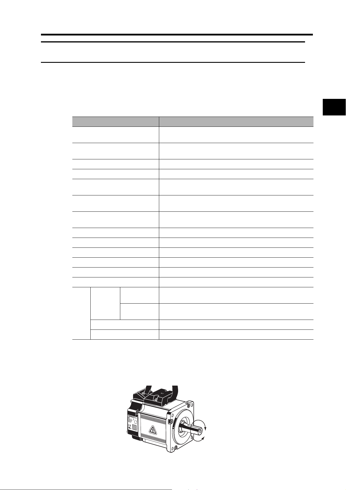
3-2 Servomotor Specifications
3-2 Servomotor Specifications
Select a Servomotor based on the mechanical system’s load conditions and the installation
environment. There are various options available on the Servomotors, such as models with brakes.
General Specifications
Item Specifications
Ambient operating temperature
Ambient operating humidity
Ambient storage temperature
Ambient storage humidity
Storage and operating atmosphere No corrosive gases
Vibration resistance 49 m/s2 max. in the X, Y, and Z directions
Impact resistance
Insulation resistance
Dielectric strength
Operating position All directions
Insulation grade Type B
Structure Totally-enclosed self-cooling
Protective structure IP65 (excluding through-shaft parts and lead wire ends)
Vibration grade V-15
Mounting method Flange-mounting
EMC
EC Directives
standards
UL standards UL 1004 File No. E179189
International
cUL standards cUL 22.2, No.100
Directive
Low Voltage
Directive
0 to 40°C, 85% RH max. (with no condensation)
−20 to 65°C, 85% RH max. (with no condensation)
2
Acceleration of 98 m/s
directions
Between the power line terminals and FG: 20 MΩ min. (at
500 VDC)
Between the power line terminals and FG: 1,500 VAC for 1 min at
50/60 Hz
EN 60034-1:2004
IEC 60034-5:2001
max. 3 times each in the X, Y, and Z
3
Specifications
Motor Rotation Directions
In this manual, the Servomotors rotation directions are defined as forward and reverse.
Viewed from the end of the motor’s output shaft, counterclockwise (CCW) rotation is forward and
clockwise (CW) rotation is reverse.
Reverse
Forward
3-16
Page 74

3-2 Servomotor Specifications
Characteristics
3,000-r/min Cylindrical Servomotors
3
Specifications
Rated output
Rated torque
Item Unit
*1
*1
W 50 100 200
N·m 0.16 0.32 0.64
R88M-
G05030H
R88M-
G10030L
Rated rotation speed r/min 3000
Max. rotation speed r/min 5000
Max. momentary torque
Rated current
*1
Max. momentary current
*1
*1
Rotor inertia kg·m
Applicable load inertia --- 30 times the rotor inertia max.
Power rate
Allowable radial load
Allowable thrust load
*1
*3
*3
N·m 0.48 0.95 1.78
A(rms) 1.1 1.7 2.5
A(rms) 3.4 5.1 7.6
2
2.5 × 10
−6
5.1 × 10
−6
*2
kW/s 10.4 20.1 30.3
N 68 68 245
N585898
Without brake kg 0.3 0.5 0.8
With brake kg 0.5 0.7 1.3
Weight
Radiation shield dimensions
(material)
Brake inertia kg·m
Excitation voltage
*4
Power consumption
(at 20°C)
Current consumption
(at 20°C)
--- 100 × 80 × t10 (Al) 130 × 120 × t12 (Al)
2
2.0 × 10
−7
2.0 × 10
−7
V 24 VDC ±10%
W779
A 0.30 0.30 0.36
Static friction torque N·m 0.29 min. 0.29 min. 1.27 min.
Attraction time
Release time
*5
*5
ms 35 max. 35 max. 50 max.
ms 20 max. 20 max. 15 max.
Backlash ±1°
Allowable work per
braking operation
Brake specifications
Allowable total work J 4.9 × 10
Allowable angular
acceleration
J 39.2 39.2 137
rad/s
3
2
30,000 max.
(Speed of 2,800 r/min or more must not be stopped in 10 ms or less)
4.9 × 10
3
Brake life --- 10,000,000 operations min.
Rating --- Continuous
Insulation grade --- Type F
R88M-
G20030L
1.4 × 10
1.8 × 10
44.1 × 10
−5
−6
3
3-17
Page 75

3-2 Servomotor Specifications
Rated output
Rated torque
Item Unit
*1
*1
W 50 100 200 400
N·m 0.16 0.32 0.64 1.3
R88M-
G05030H
R88M-
G10030H
R88M-
G20030H
Rated rotation speed r/min 3000
Max. rotation speed r/min 5000
Max. momentary torque
Rated current
*1
Max. momentary current
*1
*1
Rotor inertia kg·m
Applicable load inertia --- 30 times the rotor inertia max.
Power rate
Allowable radial load
Allowable thrust load
*1
*3
*3
N·m 0.48 0.95 1.78 3.60
A(rms)1.11.11.62.6
A(rms)3.43.44.97.9
2
2.5 × 10
−6
5.1 × 10
−6
1.4 × 10
−5
*2
kW/s 10.4 20.1 30.3 62.5
N 68 68 245 245
N58589898
Without brake kg 0.3 0.5 0.8 1.2
With brake kg 0.5 0.7 1.3 1.7
Weight
Radiation shield dimensions
(material)
Brake inertia kg·m
Excitation voltage
*4
Power consumption
(at 20°C)
Current consumption
(at 20°C)
--- 100 × 80 × t10 (Al) 130 × 120 × t12 (Al)
2
2.0 × 10
−7
2.0 × 10
−7
1.8 × 10
−6
V 24 VDC ±10%
W7799
A 0.30 0.30 0.36 0.36
Static friction torque N·m 0.29 min. 0.29 min. 1.27 min. 1.27 min.
Attraction time
Release time
*5
*5
ms 35 max. 35 max. 50 max. 50 max.
ms 20 max. 20 max. 15 max. 15 max.
Backlash ±1°
Allowable work per
braking operation
Brake specifications
Allowable total work J 4.9 × 10
Allowable angular
acceleration
J 39.2 39.2 137 196
rad/s
3
2
(Speed of 2,800 r/min or more must not be stopped in 10 ms or less)
4.9 × 10
3
30,000 max.
44.1 × 10
3
Brake life --- 10,000,000 operations min.
Rating --- Continuous
Insulation grade --- Type F
R88M-
G40030H
2.6 × 10
7.5 × 10
147 × 10
3
−5
Specifications
−6
3
*1. These are the values when the Servomotor is combined with a Servo Drive at room temperature. The maximum
momentary torque shown above indicates the standard value.
*2. For detailed information on the applicable load inertia, refer to Applicable Load Inertia on page 3-25.
*3. The allowable radial and thrust loads are the values determined for a service life of 20,000 hours at normal operating
temperatures. The values are also for the locations shown in the following diagram.
*4. The brakes are non-excitation operation type. They are released when excitation voltage is applied.
*5. The operation time is the measured value (reference value) with a varistor installed as a surge suppressor.
3-18
Page 76

3-2 Servomotor Specifications
Radial load
Center of shaft (LR/2)
3,000-r/min Flat Servomotors
Thrust load
3
Specifications
Rated output
Rated torque
Item Unit
*1
*1
W 100 200
N·m 0.32 0.64
R88M-
GP10030L
R88M-
GP20030L
Rated rotation speed r/min 3,000
Max. rotation speed r/min 5,000
Max. momentary torque
Rated current
*1
Max. momentary current
*1
*1
Rotor inertia kg·m
N·m 0.85 1.86
A(rms) 1.6 2.5
A(0-p) 6.9 10.5
2
9.0 × 10
−6
3.4 × 10
Applicable load inertia --- 20 times the rotor inertia max.
Power rate
Allowable radial load
Allowable thrust load
*1
*3
*3
kW/s 11.4 12.0
N 68 245
N58 98
Without brake kg 0.65 1.3
With brake kg 0.90 2.0
Weight
Radiation shield dimensions
(material)
Brake inertia kg·m
Excitation voltage
*4
Power consumption
(at 20°C)
Current consumption
(at 20°C)
--- 130 × 120 × t10 (Al) 170 × 160 × t12 (Al)
2
3.0 × 10
−6
9.0 × 10
V 24 VDC ±10%
W7 10
A 0.29 0.41
Static friction torque N·m 0.29 min. 1.27 min.
Attraction time
Release time
*5
*5
ms 50 max. 60 max.
ms 15 max. 15 max.
Backlash ±1°
Allowable work per
braking operation
Brake specifications
Allowable total work J 44.1 × 10
Allowable angular
acceleration
J 137 196
3
10,000 max.
rad/s
2
(Speed of 950 r/min or more must not be stopped
in 10 ms or less)
147 × 10
Brake life --- 10,000,000 operations min.
Rating --- Continuous
Insulation grade --- Type F
−5
*2
−6
3
3-19
Page 77

3-2 Servomotor Specifications
Rated output
Rated torque
Item Unit
*1
*1
W 100 200 400
N·m 0.32 0.64 1.3
R88M-
GP10030H
R88M-
GP20030H
Rated rotation speed r/min 3000
Max. rotation speed r/min 5000
Max. momentary torque
Rated current
*1
Max. momentary current
*1
*1
Rotor inertia kg·m
Applicable load inertia --- 20 times the rotor inertia max.
Power rate
Allowable radial load
Allowable thrust load
*1
*3
*3
N·m 0.90 1.82 3.60
A(rms) 1.0 1.6 4.4
A(0-p) 4.3 6.8 18.6
2
9.0 × 10
−6
3.4 × 10
−5
*2
kW/s 11.4 11.8 25.5
N 68 245 245
N589898
Without brake kg 0.7 1.3 1.8
With brake kg 0.9 2.0 2.5
Weight
Radiation shield dimensions
(material)
Brake inertia kg·m
Excitation voltage
*4
Power consumption
(at 20°C)
Current consumption
(at 20°C)
--- 130 × 120 × t10 (Al) 170 × 160 × t12 (Al)
2
3.0 × 10
−6
9.0 × 10
−6
V 24 VDC ±10%
W 7 10 10
A 0.29 0.41 0.41
Static friction torque N·m 0.29 min. 1.27 min. 1.27 min.
Attraction time
Release time
*5
*5
ms 50 max. 60 max. 60 max.
ms 15 max. 15 max. 15 max.
Backlash ±1°
Allowable work per
braking operation
Brake specifications
Allowable total work J 44.1 × 10
Allowable angular
acceleration
J 137 196 196
rad/s
3
2
147 × 10
10,000 max.
(Speed of 950 r/min or more must not be stopped in 10 ms or less)
3
Brake life --- 10,000,000 operations min.
Rating --- Continuous
Insulation grade --- Type F
R88M-
GP40030H
−5
6.4 × 10
−6
9.0 × 10
147 × 10
3
Specifications
3
*1. These are the values when the Servomotor is combined with a Servo Drive at room temperature. The maximum
momentary torque shown above indicates the standard value.
*2. For detailed information on the applicable load inertia, refer to Applicable Load Inertia on page 3-25.
*3. The allowable radial and thrust loads are the values determined for a service life of 20,000 hours at normal
operating temperatures. The values are also for the locations shown in the following diagram.
*4. The brakes are non-excitation operation type. They are released when excitation voltage is applied.
*5. The operation time is the measured value (reference value) with a varistor installed as a surge suppressor.
3-20
Page 78
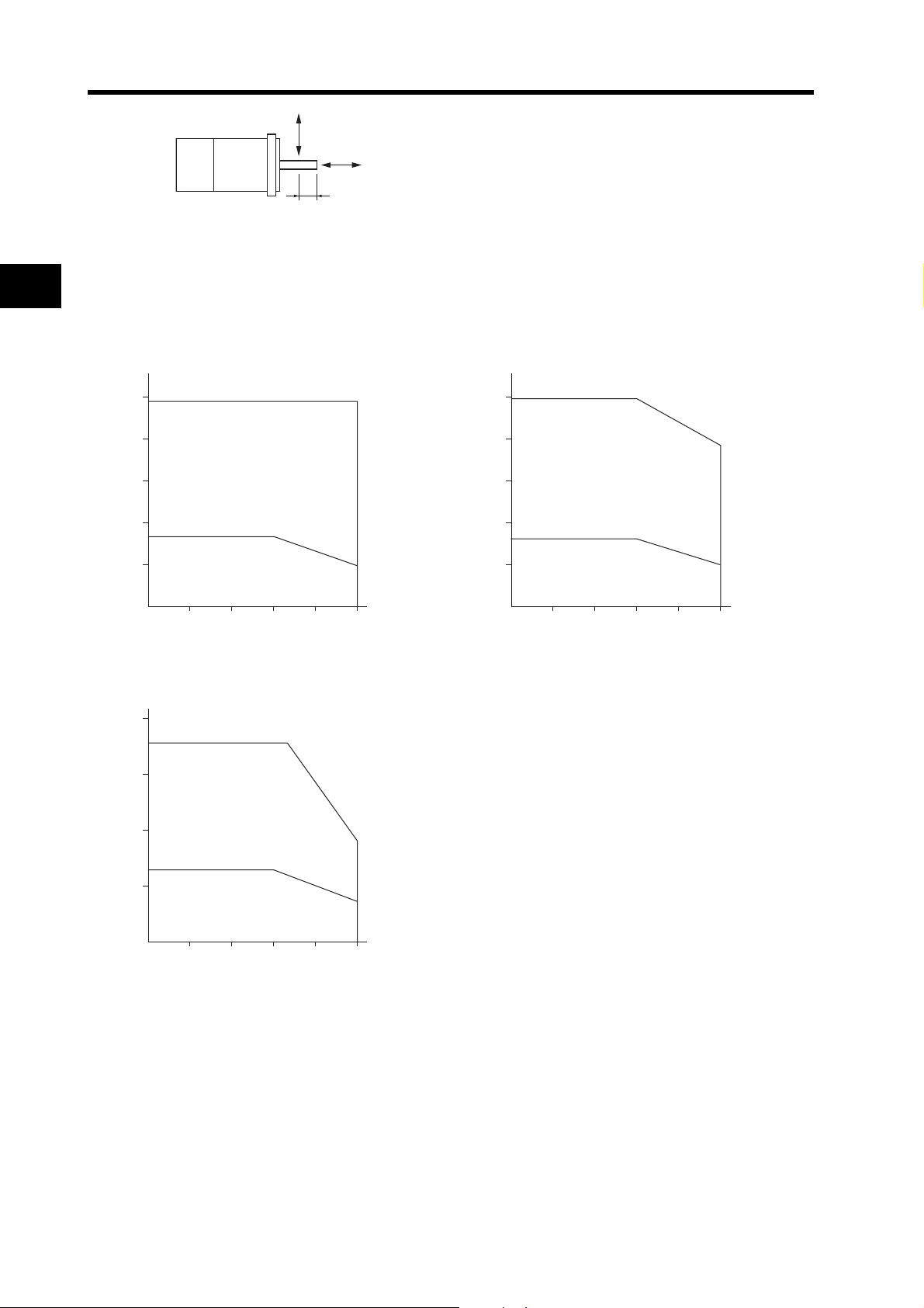
3-2 Servomotor Specifications
Radial load
Thrust load
Center of shaft (LR/2)
Torque and Rotation Speed Characteristics
3
Specifications
3,000-r/min Cylindrical Servomotors
The following graphs show the characteristics with a 3-m standard cable and a 100-VAC input.
R88M-G05030H R88M-G10030L
(N·m)
0.5
0.4
0.3
0.2
0.1
0
1000 2000 3000 4000 5000
R88M-G20030L
(N·m)
2.0
1.78
1.5
Repetitive usage
0.160.16
Continuous usage
1.78
(3300)
0.48
0.09
(r/min)
(N·m)
1.0
0.8
0.6
0.4
0.2
0.95
Repetitive usage
0.32
Continuous usage
0
1000 2000 3000 4000 5000
0.95
(3000)
0.77
0.32
0.20
(r/min)
3-21
1.0
0.5
Repetitive usage
0.640.64
Continuous usage
0
1000 2000 3000 4000 5000
0.90
0.36
(r/min)
Page 79

3-2 Servomotor Specifications
The following graphs show the characteristics with a 3-m standard cable and a 200-VAC input.
R88M-G10030H R88M-G20030H
(N·m)
1.0
0.8
0.6
0.4
0.2
0
1000 2000 3000 4000 5000
R88M-G40030H
(N·m)
4.0
3.60
3.0
Repetitive usage
2.0
Repetitive usage
0.320.32
Continuous usage
3.60
(3200)
0.95
0.19
2.1
(r/min)
(N·m)
2.0
1.5
1.0
0.5
1.82
Repetitive usage
0.64
Continuous usage
0
1000 2000 3000 4000 5000
0.64
1.82 (4300)
1.65
3
0.36
(r/min)
Specifications
1.31.3
1.0
Continuous usage
0
1000 2000 3000 4000 5000
0.88
(r/min)
3,000-r/min Flat Servomotors
The following graphs show the characteristics with a 3-m standard cable and a 100-VAC input.
R88M-GP10030L R88M-GP20030L
(N·m) (N·m)
2.0
1.0
0.8
0.6
0.4
0.2
0.85
0.85 (4100)
0.75
Repetitive usage
0.320.32
0.22
Continuous usage
1.86
1.5
Repetitive usage
1.0
0.64
0.5
Continuous usage
1.86
0.64
(3400)
0.7
0.32
0
1000 2000 3000 4000 5000
(r/min) (r/min)
0
1000 2000 3000 4000 5000
3-22
Page 80
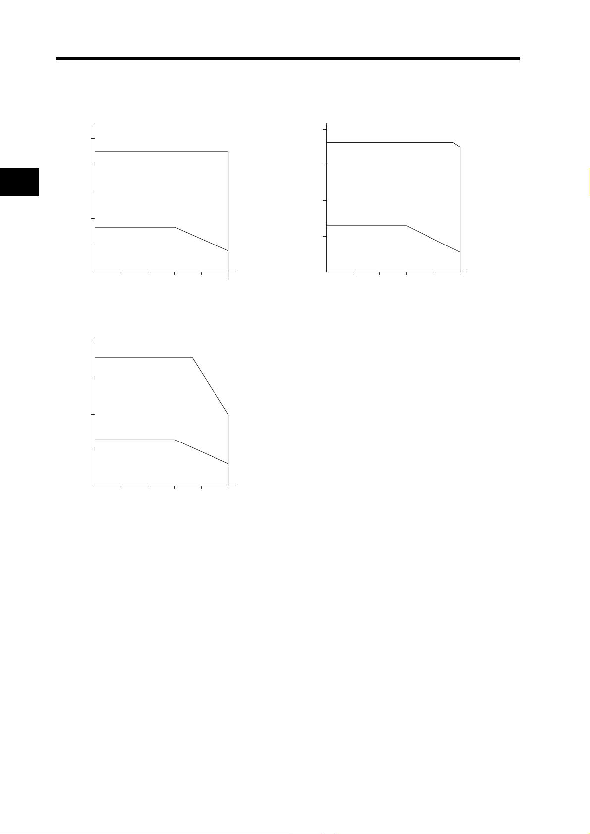
3-2 Servomotor Specifications
The following graphs show the characteristics with a 3-m standard cable and a 200-VAC input.
R88M-GP10030H R88M-GP20030H
3
Specifications
(N·m)
1.0
0.90
0.8
0.6
0.4
0.2
0
R88M-GP40030H
(N·m)
4.0
3.60
3.0
Repetitive usage
Continuous usage
1000 2000 3000 4000 5000
Repetitive usage
(N·m)
2.0
1.82
0.90
1.5
Repetitive usage
1.0
0.5
0.64
Continuous usage
0
1000 2000 3000 4000 5000
0.320.32
0.16
(r/min)
3.60
(3600)
0.64
1.82 (4700)
1.75
0.28
(r/min)
2.0
1.0
1.31.3
Continuous usage
0
1000 2000 3000 4000 5000
2.0
0.64
(r/min)
Temperature Characteristics of the Servomotor and Mechanical System
OMNUC G-Series Servomotors use rare earth magnets (neodymium-iron magnets).
The temperature coefficient for these magnets is approximately −0.13%/°C. As the temperature
drops, the Servomotor's maximum momentary torque increases, and as the temperature rises, the
Servomotor's maximum momentary torque decreases.
The maximum momentary torque rises by 4% at a normal temperature of 20°C compared to a
temperature of −10°C. Conversely, the maximum momentary torque decreases about 8% when
the magnet warms up to 80°C from the normal temperature of 20°C.
Generally, when the temperature drops in a mechanical system, the friction torque and the load
torque increase. For that reason, overloading may occur at low temperatures. In particular, in
systems that use a Decelerator, the load torque at low temperatures may be nearly twice as much
as the load torque at normal temperatures. Check whether overloading may occur at low
temperature startup. Also check to see whether abnormal Servomotor overheating or alarms occur
at high temperatures.
An increase in load friction torque seemingly increases load inertia. Therefore, even if the Servo
Drive gains are adjusted at a normal temperature, the Servomotor may not operate properly at low
temperatures. Check to see whether there is optimal operation even at low temperatures.
3-23
Page 81

3-2 Servomotor Specifications
Precautions
for Correct Use
50 W (Without Oil Seal)
Rated Torque Ratio (%)
100
80
60
40
20
0
10 20 30 40
100 W (Without Oil Seal)
Rated Torque Ratio (%)
100
80
60
Use Cylindrical Servomotors in the ranges shown in the following graphs.
Using outside of these ranges may cause the Servomotor to generate
heat, which could result in encoder malfunction.
50 W (With Oil Seal)
With brake
95%
Ambient temperature
With brake
95%
Rated Torque Ratio (%)
100
80
60
40
20
0
10 20 30 40
100 W (With Oil Seal)
Rated Torque Ratio (%)
100
80
60
Without brake
With brake
70%
60%
Ambient temperature
Without brake
With brake
75%
70%
3
Specifications
40
20
0
10 20 30 40
Ambient temperature
40
20
0
10 20 30 40
Ambient temperature
3-24
Page 82

3-2 Servomotor Specifications
200 W (With Oil Seal)
Rated Torque Ratio (%)
100
80
60
3
40
20
Without brake
With brake
80%
70%
Rated Torque Ratio (%)
100
Specifications
Applicable Load Inertia
400 W (Without Oil Seal)
80
60
40
20
0
10 20 30 40
The drivable load inertia ratio (load inertia/rotor inertia) depends on the configuration and rigidity
of the machine being driven. Machines with high rigidity can be operated with a large load inertia.
Select the appropriate Servomotor and confirm the applicable load inertia.
Frequently operating a dynamic brake with a large load inertia may burn the dynamic brake
resistor. Do not turn ON/OFF the Servomotor frequently with the dynamic brake enabled.
With brake
90%
Ambient temperature
0
10 20 30 40
400 W (With Oil Seal)
Rated Torque Ratio (%)
100
80
60
40
20
0
10 20 30 40
Ambient temperature
With brake
75%
Ambient temperature
Encoder Specifications
Item Specifications
Encoder system Optical encoder (incremental encoder)
No. of output pulses Phases A and B: 2,500 pulses/rotation, Phase Z: 1 pulse/rotation
Power supply voltage 5 V ±5%
Power supply current 180 mA (max.)
Output signals +S, −S
Output interface
3-25
EIA-RS-485 compliance
Bidirectional serial communications data
Page 83

3-3 Decelerator Specifications
3-3 Decelerator Specifications
The following Decelerators are available for use with OMNUC G-Series Servomotors. Select a
Decelerator matching the Servomotor capacity.
Standard Models and Specifications
Backlash = 3’ Max.
Decelerators for Cylindrical Servomotors
Rated
Model
(R88G-)
1/5 HPG11B05100B 600 0.50 63 1000 1.51 5.00
1/9 HPG11B09050B 333 1.12 78 555 3.36 3.00
50
1/21 HPG14A21100B 143 2.18 65 238 6.54 5.00
W
1/33 HPG14A33050B 91 3.73 71 151 11.2 4.40
1/45 HPG14A45050B 67 5.09 71 111 15.2 4.40
1/5 HPG11B05100B 600 1.28 80 1000 3.6 5.00
1/11 HPG14A11100B 273 2.63 75 454 7.80 6.00
100
1/21 HPG14A21100B 143 5.40 80 238 16.0 5.00
W
1/33 HPG20A33100B 91 6.91 65 151 20.5 6.50
1/45 HPG20A45100B 67 9.42 65 111 27.9 6.50
1/5 HPG14A05200B 600 2.49 78 1000 7.44 2.07
1/11 HPG14A11200B 273 6.01 85 454 17.9 1.93
200
1/21 HPG20A21200B 143 10.2 76 238 30.6 4.90
W
1/33 HPG20A33200B 91 17.0 81 151 50.8 4.50
1/45 HPG20A45200B 67 23.2 81 111 69.3 4.50
1/5 HPG14A05400B 600 5.66 87 1000 16.5 2.07
1/11 HPG20A11400B 273 11.7 82 454 34.2 5.70
400
1/21 HPG20A21400B 143 23.5 86 238 68.8 4.90
W
1/33 HPG32A33400B 91 34.7 81 151 101.7 6.20
1/45 HPG32A45400B 67 47.4 81 111 138.6 6.10
rota-
speed
r/min N·m % r/min N·m kg·m
tion
Rated
torque
Effi-
cien-
cy
Maxi-
mum
momen-
tary
rotation
speed
Maxi-
mum
momen-
tary
torque
Decelera-
tor
inertia
2
×10
×10
×10
×10
×10
×10
×10
×10
×10
×10
×10
×10
×10
×10
×10
×10
×10
×10
×10
×10
Allow-
radial
−7
−7
−6
−6
−6
−7
−6
−6
−5
−5
1006 3541 2.4
−5
−5
−5
−5
−5
1006 3541 2.9
−5
−5
−5
−5
1565 6240 7.5
−5
1718 6848 7.5
Allow-
able
load
135 538 0.29
161 642 0.29
340 1358 1.04
389 1555 1.04
able
thrust
load
N N kg
427 1707
135 538 0.29
280 1119 1.04
340 1358 1.04
916 3226 2.4
221 883 1.02
280 1119 1.09
800 2817 2.9
916 3226 2.9
221 883 1.09
659 2320 2.9
800 2547 2.9
3
Weight
Specifications
1.04
Note 1. The Decelerator inertia is the Servomotor shaft conversion value.
Note 2. The protective structure of Servomotors with Decelerators satisfies IP44.
Note 3. The allowable radial load is the value at the T/2 position.
Note 4. The standard models have a straight shaft. Models with a key and tap are indicated with “J” at the end
of the model number (the suffix in the box).
Note 5. If the R88G-HPG11B05100B(J) is cold-started, the efficiency will decrease because the viscosity of
the lubricant in the Decelerator will increase. If the operation is continued until the temperature of the
Decelerator increases, the viscosity of the lubricant will decrease and the efficiency will increase.
3-26
Page 84

3-3 Decelerator Specifications
Decelerator for Flat Servomotors
3
Specifications
Maxi-
cy
mum
momen-
tary
rotation
speed
1000
(900)
454
(409)
238
(214)
151
(136)
111
(100)
momen-
Rated
Model
(R88G-)
1/5 HPG11B05100PB 600 1.28 80 1000
1/11 HPG14A11100PB 273 2.63 75 454
100
1/21 HPG14A21100PB 143 5.40 80 238
W
1/33 HPG20A33100PB 91 6.91 65 151
1/45 HPG20A45100PB 67 9.42 65 111
1/5 HPG14A05200PB 600 2.49 78 1000 7.09 2.07
1/11 HPG20A11200PB 273 4.75 68 454 13.5 5.80
200
1/21 HPG20A21200PB 143 10.2 76 238 29.2 4.90
W
1/33 HPG20A33200PB 91 17.0 81 151 48.5 4.50
1/45 HPG20A45200PB 67 23.2 81 111 66.1 4.50
1/5 HPG20A05400PB 600 4.67 72
1/11 HPG20A11400PB 273 11.7 82
400
1/21 HPG20A21400PB 143 23.5 86
W
1/33 HPG32A33400PB 91 34.7 81
1/45 HPG32A45400PB 67 47.4 81
rota-
speed
r/min N·m % r/min N·m kg·m
tion
Rated
torque
Effi-
cien-
Maximum
tary
torque
3.6
(3.4)
7.39
(6.98)
15.2
(14.6)
19.4
(18.3)
26.5
(25.0)
12.9 7.10
32.4 5.80
65.2 4.90
96.2 2.80
131.2 2.80
Decelera-
5.00
6.00
5.00
4.50
4.50
tor
inertia
×10
×10
×10
×10
×10
×10
×10
×10
×10
×10
×10
×10
×10
×10
×10
Allow-
able
radial
load
2
−7
135 538 0.34
−6
280 1119 1.04
−6
340 1358 1.04
−5
916 3226 2.9
−5
1006 3541 2.9
−5
221 883 0.99
−5
659 2320 3.1
−5
800 2817 3.1
−5
916 3226 3.1
−5
1006 3541 3.1
−5
520 1832 3.1
−5
659 2320 3.1
−5
800 2817 3.1
−4
1565 6240 7.8
−4
1718 6848 7.8
Allow-
thrust
N N kg
able
load
Weight
Note 1. The Decelerator inertia is the Servomotor shaft conversion value.
Note 2. The protective structure of Servomotors with Decelerators satisfies IP44.
Note 3. The allowable radial load is the value at the T/2 position.
Note 4. The standard models have a straight shaft. Models with a key and tap are indicated with “J” at the end
of the model number (the suffix in the box).
Note 5. The values in parentheses ( ) are those when using a 100-V motor.
3-27
Page 85

Backlash = 15’ Max.
Decelerators for Cylindrical Servomotors
3-3 Decelerator Specifications
Maxi-
cy
mum
momen-
tary
rotation
speed
momen-
Rated
Model
(R88G-)
1/5 VRSF05B100CJ 600 0.52 65 1000 1.55 4.00
1/9 VRSF09B100CJ 333 0.93 65 556 2.79 3.50
50
W
1/15 VRSF15B100CJ 200 1.67 70 333 5.01 3.50
1/25 VRSF25B100CJ 120 2.78 70 200 8.34 3.25
1/5 VRSF05B100CJ 600 1.19 75 1000 3.57 4.00
1/9 VRSF09B100CJ 333 2.29 80 556 6.87 3.50
100
W
1/15 VRSF15B100CJ 200 3.81 80 333 11.4 3.50
1/25 VRSF25B100CJ 120 6.36 80 200 19.0 3.25
1/5 VRSF05B200CJ 600 2.70 85 1000 8.10 1.18
1/9 VRSF09C200CJ 333 3.77 66 556 11.3 2.75
200
W
1/15 VRSF15C200CJ 200 6.29 66 333 18.8 3.00
1/25 VRSF25C200CJ 120 11.1 70 200 33.3 2.88
1/5 VRSF05C400CJ 600 5.40 85 1000 16.2 3.63
1/9 VRSF09C400CJ 333 9.50 83 556 28.5 2.75
400
W
1/15 VRSF15C400CJ 200 15.8 83 333 47.4 3.00
1/25 VRSF25C400CJ 120 26.4 83 200 79.2 2.88
rota-
speed
r/min N·m % r/min N·m kg·m
tion
Rated
torque
Effi-
cien-
Maxi-
mum
tary
torque
Decelera-
tor
inertia
2
×10
×10
×10
×10
×10
×10
×10
×10
×10
×10
×10
×10
×10
×10
×10
×10
Allow-
able
radial
load
−6
392 196 0.55
−6
441 220 0.55
−6
588 294 0.70
−6
686 343 0.70
−6
392 196 0.55
−6
441 220 0.55
−6
588 294 0.70
−6
686 343 0.70
−5
392 196 0.72
−5
931 465 1.70
−5
1176 588 2.10
−5
1323 661 2.10
−5
784 392 1.70
−5
931 465 1.70
−5
1176 588 2.10
−5
1323 661 2.10
Allow-
able
thrust
load
N N kg
Weight
3
Specifications
Note 1. The Decelerator inertia is the Servomotor shaft conversion value.
Note 2. The protective structure of Servomotors with Decelerators satisfies IP44.
Note 3. The allowable radial load is the value at the T/2 position.
Note 4. The standard models have a straight shaft with a key.
3-28
Page 86

3-3 Decelerator Specifications
Decelerator for Flat Servomotors
3
Specifications
Maxi-
Rated
Model
(R88G-)
1/5 VRSF05B100PCJ 600 1.19 75 1000
1/9 VRSF09B100PCJ 333 2.29 80 556
100
W
1/15 VRSF15B100PCJ 200 3.81 80 333
1/25 VRSF25B100PCJ 120 6.36 80 200
1/5 VRSF05B200PCJ 600 2.70 85 1000 7.74 1.18
1/9 VRSF09C200PCJ 333 3.77 66 556 10.8 2.75
200
W
1/15 VRSF15C200PCJ 200 6.29 66 333 18.0 3.00
1/25 VRSF25C200PCJ 120 11.1 70 200 31.8 2.88
1/5 VRSF05C400PCJ 600 5.40 85
1/9 VRSF09C400PCJ 333 9.50 83
400
W
1/15 VRSF15C400PCJ 200 15.8 83
1/25 VRSF25C400PCJ 120 26.4 83
rota-
speed
r/min N·m % r/min N·m kg·m
tion
Rated
torque
Effi-
cien-
cy
mum
momen-
tary
rotation
speed
1000
(900)
556
(500)
333
(300)
200
(180)
Maxi-
mum
momen-
tary
torque
3.38
(3.19)
6.48
(6.12)
10.8
(10.2)
18.0
(17.0)
15.3 3.63
26.9 2.75
44.8 3.00
74.7 2.88
Decelera-
tor
inertia
2
×10
4.00
×10
3.50
×10
3.50
×10
3.25
×10
×10
×10
×10
×10
×10
×10
×10
Allow-
radial
−6
−6
−6
−6
−5
−5
−5
1176 588 2.20
−5
1323 661 2.20
−5
−5
−5
1176 588 2.20
−5
1323 661 2.20
Allow-
able
load
392 196 0.72
441 220 0.72
588 294 0.87
686 343 0.87
392 196 0.85
931 465 1.80
784 392 1.80
931 465 1.80
able
thrust
load
N N kg
Weight
Note 1. The Decelerator inertia is the Servomotor shaft conversion value.
Note 2. The protective structure of Servomotors with Decelerators satisfies IP44.
Note 3. The allowable radial load is the value at the T/2 position.
Note 4. The standard models have a straight shaft with a key.
Note 5. The values in parentheses ( ) are those when using a 100-V motor.
3-29
Page 87

3-4 Cable and Connector Specifications
3-4 Cable and Connector Specifications
Encoder Cable Specifications
These cables are used to connect the encoder between the Servo Drive and Servomotor. Encoder
Cables with connectors for CN2 are available.
3
Precautions
for Correct Use
Use robot cables for applications with moving parts.
Standard Cables for Encoders
Cable Models
Model Length (L)
R88A-CRGB003C 3 m
R88A-CRGB005C 5 m Approx. 0.3 kg
R88A-CRGB010C 10 m Approx. 0.6 kg
R88A-CRGB015C 15 m Approx. 0.9 kg
R88A-CRGB020C 20 m Approx. 1.2 kg
*1. The maximum distance between the Servo Drive and Servomotor is 20 m.
Connection Configuration and External Dimensions
Servo Drive end
R7D-BP@
*1
L
6.5 dia.
Outer diameter of sheath Weight
Approx. 0.2 kg
6.5 dia.
Servomotor end
R88M-G@
11.8
Specifications
4144
Wiring
Servo Drive Servomotor
No.
14
25
5
6
31
46
Shell
Servo Drive Connector
Connector pins:
50639-8028 (Molex Japan)
Connector case:
Crimp-type I/O Connector (Molex Japan)
Signal
E5V
E0V
S+
S−
NC
NC
FG
Red
Black
Orange
Orange
/White
AWG22
AWG22
AWG24
AWG24
No.
2
3
Servomotor Connector
Connector pins:
170365-1 (Tyco Electronics AMP KK)
Connector case:
172160-1 (Tyco Electronics AMP KK)
Signal
E5V
E0V
S+
S−
NC
FG
3-30
Page 88

3-4 Cable and Connector Specifications
Robot Cables for Encoders
Cable Models
Model Length (L)
*1
Outer diameter of sheath Weight
3
Specifications
R88A-CRGB003CR 3 m
R88A-CRGB005CR 5 m Approx. 0.4 kg
R88A-CRGB010CR 10 m Approx. 0.8 kg
7.5 dia.
R88A-CRGB015CR 15 m Approx. 1.1 kg
R88A-CRGB020CR 20 m Approx. 1.5 kg
*1. The maximum distance between the Servo Drive and Servomotor is 20 m.
Connection Configuration and External Dimensions
L
Servo Drive end
R7D-BP@
7.5 dia.
Wiring
Servo Drive
Servomotor end
11.8
4144
Servomotor
Approx. 0.2 kg
R88M-G@
No.
14
25
5
6
31
46
Shell
Servo Drive Connector
Connector pins:
50639-8028 (Molex Japan)
Connector case:
Crimp-type I/O Connector (Molex Japan)
Signal
E5V
E0V
S+
S−
NC
NC
FG
Blue
/Red
Blue
/Black
Pink
/Red
Pink
/Black
Orange
/Red
Orange
/Black
AWG24
AWG24
AWG24
AWG24
AWG24
AWG24
No.
Signal
E5V
E0V
2
3
S+
S−
NC
FG
Servomotor Connector
Connector pins:
170365-1 (Tyco Electronics AMP KK)
Connector case:
172160-1 (Tyco Electronics AMP KK)
3-31
Page 89

3-4 Cable and Connector Specifications
Servomotor Power Cable Specifications
These are the cables connecting between the Servo Drive and Servomotor.
Servomotor Power Cables with connectors for the CNB are available.
When using Cables for a Servomotor with a brake, a Brake Cable is also required. Brake cables are
also available as standard cables and robot cables.
Precautions
for Correct Use
Use robot cables for applications with moving parts.
Standard Cables for Servomotor Power (with CNB Connector)
Cable Models
Model Length (L)
R7A-CAB003S 3 m
R7A-CAB005S 5 m Approx. 0.3 kg
R7A-CAB010S 10 m Approx. 0.6 kg
R7A-CAB015S 15 m Approx. 0.9 kg
R7A-CAB020S 20 m Approx. 1.2 kg
*1. The maximum distance between the Servo Drive and Servomotor is 20 m.
Connection Configuration and External Dimensions
50 50L
Servo Drive end
R7D-BP@
*1
6.2 dia.
Outer diameter of sheath Weight
dia.
6.2
Servomotor end
12.0
10.0
44
3
Approx. 0.2 kg
Specifications
R88M-G@
Wiring
Servo Drive Servomotor
No.
1
4
6
3
2
5
Servo Drive Connector
Connector pins:
5556PBTL (Molex Japan)
Connector case:
5557-06R-210 (Molex Japan)
Signal
Phase-U
Phase-V
Phase-W
FG
Red
White
Blue
Green/Yellow
Cable: AWG20 × 4C UL2464
No.
1
2
3
4
Signal
Phase-U
Phase-V
Phase-W
FG
Servomotor Connector
Connector pins:
170366-1 or 170362-1
(Tyco Electronics AMP KK)
Connector case:
172159-1 (Tyco Electronics AMP KK)
3-32
Page 90

3-4 Cable and Connector Specifications
Robot Cables for Servomotor Power (with CNB Connector)
Cable Models
Model Length (L)
R7A-CAB003SR 3 m
R7A-CAB005SR 5 m Approx. 0.3 kg
*1
Outer diameter of sheath Weight
Approx. 0.2 kg
3
Specifications
R7A-CAB010SR 10 m Approx. 0.7 kg
R7A-CAB015SR 15 m Approx. 1.0 kg
R7A-CAB020SR 20 m Approx. 1.3 kg
*1. The maximum distance between the Servo Drive and Servomotor is 20 m.
Connection Configuration and External Dimensions
50 50L
Servo Drive end
R7D-BP@
6.9 dia.
Wiring
Servo Drive
No.
1
4
6
3
2
Signal
Phase-U Phase-U
Phase-V
Phase-W
FG FG
Red
White
Black
Green/Yellow
Cable: AWG20 × 4C UL2464
dia.
6.9
12.0
10.0
44
Servomotor
No.
1
2
3
4
Servomotor end
R88M-G@
Signal
Phase-V
Phase-W
5
Servo Drive Connector
Connector pins:
5556PBTL (Molex Japan)
Connector case:
5557-06R-210 (Molex Japan)
3-33
Servomotor Connector
Connector pins:
170366-1 or 170362-1
(Tyco Electronics AMP KK)
Connector case:
172159-1 (Tyco Electronics AMP KK)
Page 91

Standard Cables for Brakes
Cable Models
Model Length (L)
R88A-CAGA003B 3 m
R88A-CAGA005B 5 m Approx. 0.2 kg
3-4 Cable and Connector Specifications
*1
Outer diameter of sheath Weight
Approx. 0.1 kg
R88A-CAGA010B 10 m Approx. 0.4 kg
R88A-CAGA015B 15 m Approx. 0.6 kg
R88A-CAGA020B 20 m Approx. 0.8 kg
*1. The maximum distance between the Servo Drive and Servomotor is 20 m.
5.4
Connection Configuration and External Dimensions
50 50
Servo Drive end
R7D-BP@
L
5.4 dia.
Wiring
Servo Drive Servomotor
M4 crimp
terminal
Black
Brown
Cable: AWG20 × 2C UL2464
No.
A
B
Servomotor Connector
Connector pins:
170366-1 or 170362-1
(Tyco Electronics AMP KK)
Connector case:
172157-1
(Tyco Electronics AMP KK)
Signal
Brake
Brake
dia.
12.0
5.6
Servomotor end
10.0
R88M-G@
3
Specifications
3-34
Page 92

3-4 Cable and Connector Specifications
Robot Cables for Brakes
Cable Models
Model Length (L)
R88A-CAGA003BR 3 m
R88A-CAGA005BR 5 m Approx. 0.2 kg
*1
Outer diameter of sheath Weight
Approx. 0.1 kg
3
Specifications
R88A-CAGA010BR 10 m Approx. 0.4 kg
R88A-CAGA015BR 15 m Approx. 0.7 kg
R88A-CAGA020BR 20 m Approx. 0.9 kg
*1. The maximum distance between the Servo Drive and Servomotor is 20 m.
6.1
Connection Configuration and External Dimensions
50 50
Servo Drive end
R7D-BP@
L
6.1 dia.
Wiring
Servo Drive Servomotor
No.
M4 crimp
terminal
Black
White
Cable: AWG20 × 2C UL2464
A
B
Servomotor Connector
Connector pins:
170366-1 or 170362-1
(Tyco Electronics AMP KK)
Connector case:
172157-1
(Tyco Electronics AMP KK)
dia.
12.0
5.6
Signal
Brake
Brake
Servomotor end
10.0
R88M-G@
3-35
Page 93
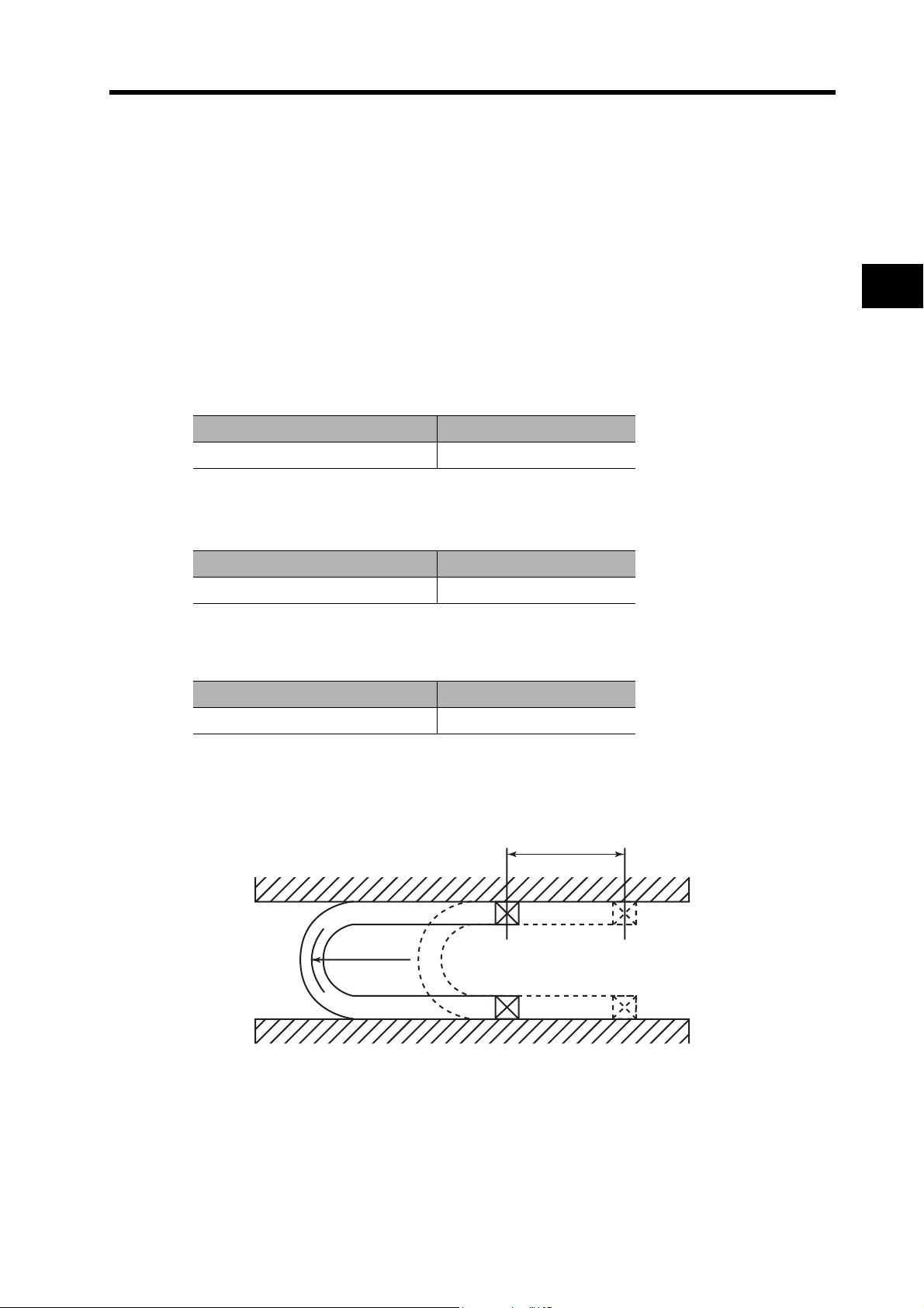
3-4 Cable and Connector Specifications
Resistant to Bending of Robot Cables
Use Robot Cable that can withstand at least 20 million bends to the minimum bending radius (R)
given below or larger.
Note 1. The service life data for resistant to bending is based on test data. Use it for reference only,
and provide sufficient allowance.
Note 2. This value is the number of bends when electricity is conducted through the conductors that
will not result in cracking or damage to an extent that would affect the functionality of the
sheath. Broken shield strands may occur.
Note 3. If a bending radius smaller than the minimum bending radius is used, it may result in
mechanical damage or ground fault damage due to insulation breakdown. If it is necessary
to use a bending radius smaller than the minimum bending radius, consult with your
OMRON representative.
Encoder Cables
Model Minimum bending radius (R)
R88A-CRGA@@@CR 45 mm
3
@@@: 003 to 020
Power Cables
Model Minimum bending radius (R)
R7A-CAB@@@SR 45 mm
@@@: 003 to 020
Brake Cables
Model Minimum bending radius (R)
R88A-CAGA@@@BR 45 mm
@@@: 003 to 020
Moving Bend Test
Specifications
Stroke:
750 mm
Bending
radius (R)
*1. Encoder cable: 30 to 50 m only
Stroke: 550 mm, 50 times/min
30 times/min
3-36
Page 94

3-4 Cable and Connector Specifications
Power Cable Specifications
This is the Cable that supplies power to the Servo Drive.
Power Cables are available in two forms: single-phase and three-phase. Select the Cable matching
the Servo Drive to be used.
When connecting an External Regeneration Resistor, use an External Regeneration Resistor
Cable.
3
Specifications
Single-phase Power Cable (with CNA Connector)
Cable Models
Model Length (L) Outer diameter of sheath Weight
R7A-CLB002S2
Connection Configuration and External Dimensions
Power supply end
Single-phase
100/200 VAC
Wiring
Power supply end Servo Drive
2 m 6.1 dia. Approx. 0.1 kg
50 502000
6.1 dia.
No.
1
Servo Drive end
R7D-BP@
Signal
FG
M4 crimp
terminal
Blue
Red
Cable: AWG18 × 2C UL2464
2
3
4
5
6L3
7
8
9
10 L1
B1
P
L2
Servo Drive Connector
Connector pins:
5556PBTL (Molex Japan)
Connector case:
5557-10R-210 (Molex Japan)
3-37
Page 95

3-4 Cable and Connector Specifications
Three-phase Power Cable (with CNA Connector)
Cable Models
Model Length (L) Outer diameter of sheath Weight
R7A-CLB002S3
2 m 6.4 dia. Approx. 0.1 kg
Connection Configuration and External Dimensions
50 502000
Power supply end
Three-phase
200 VAC
6.4 dia.
Wiring
Power supply end Servo Drive
No.
1
2
3
4
3
Servo Drive end
R7D-BP@
Specifications
Signal
FG
B1
M4 crimp
terminal
Blue
White
Red
Cable: AWG18 × 3C UL2464
5
6L3
7
8
9
10 L1
P
L2
Servo Drive Connector
Connector pins:
5556PBTL (Molex Japan)
Connector case:
5557-10R-210 (Molex Japan)
3-38
Page 96

3-4 Cable and Connector Specifications
External Regeneration Resistor Connection Cable (with Crimp Pins)
Cable Models
Model Length (L) Outer diameter of sheath Weight
3
Specifications
R7A-CLB002RG
2 m 6.1 dia. Approx. 0.1 kg
Connection Configuration and External Dimensions
50 502000
External Regeneration Resistor
end
R88A-RR22047S
R88A-RR080100S
R88A-RR08050S
6.1 dia.
Wiring
Insert into the P (pin 5) and B1 (pin 3) slots of the Main Circuit Connector (CNA).
10
L19(NC)8L27(NC)6L3
5
P
4
(NC)3B12(NC)1FG
Servo Drive end
R7D-BP@
3-39
Page 97

3-4 Cable and Connector Specifications
Communications Cable Specifications
Personal Computer Monitor Cable
Cable Models
Model Length (L) Outer diameter of sheath Weight
R88A-CCG002P2
2 m 4.2 dia. Approx. 0.1 kg
Connection Configuration and External Dimensions
ersonal computer end
Wiring
Personal computer
Signal
Shell Shell
PC Connector
17JE-13090-02 (D8A) (DDK Ltd.)
Precautions
for Correct Use
Cable: AWG28 x 3C UL20276
Communications with the Host Device
After confirming the startup of the Servo Drive, initiate communications
with the host device.
Note that irregular signals may be received from the host interface during
startup. For this reason, take appropriate initialization measures such as
clearing the receive buffer.
3
Servo Drive end
R7D-BP@
Specifications
Servo Drive
Signal
3-40
Page 98

3-4 Cable and Connector Specifications
Connector Specifications
Main Circuit Connector (R7A-CNB01P)
The Main Circuit Connector connects to the Servo Drive’s Main Circuit Connector (CNA).
Dimensions
3
Specifications
5.4
3
4.2
2.7 2.7
16.8
22.2
4.2
9.6
8.56.3
11.6
10.7
19.6
3.5
Connector pins:
5556PBTL (Molex Japan)
Connector case:
5557-10R-210 (Molex Japan)
3-41
Page 99

Servomotor Connector (R7A-CNB01A)
The Servomotor Connector connects to the Servo Drive’s Servomotor Connector (CNB).
Dimensions
3-4 Cable and Connector Specifications
5.4
3
4.2
4.2
2.7 2.7
8.4
13.8
8.56.3
9.6
11.6
3.5
Control I/O Connector (R88A-CNW01C)
This Connector connects to the Control I/O Connector (CN1) of the Servo Drive.
Use this Connector when preparing a control cable yourself.
Dimensions
39
10.7
19.6
Connector pins:
5556PBTL (Molex Japan)
Connector case:
5557-06R-210 (Molex Japan)
3
Specifications
t = 14
Connector plug:
37.2
10126-3000PE (Sumitomo 3M)
Connector case:
10326-52A0-008 (Sumitomo 3M)
3-42
Page 100

3
Specifications
3-4 Cable and Connector Specifications
Encoder Connectors
These Connectors are used for Encoder Cables.
Use them when preparing an encoder cable yourself.
R88A-CNW01R (CN2 Servo Drive Connector)
This connector is soldering type.
Use the following cable.
Applicable wire: AWG16 max.
Insulating cover outer diameter: 2.1 mm max.
Sheath outer diameter: 6.7±0.5 mm
Dimensions
Connector plug:
55100-0670 (Molex Japan Co.)
R88A-CNG02R (Servomotor Connector)
Use the following cable.
Applicable wire: AWG22 max.
Insulating cover outer diameter: 1.75 mm max.
8.4
2.8 4.2
11.8
9.8
±0.4
±0.15
)
4
(
±0.15
14
2.84.2
23.7
*1
±0.4
(
8.8
)
Connector housing: 172160-1 (Tyco Electronics AMP KK)
Contact socket: 170365-1 (Tyco Electronics AMP KK)
Applicable panel thickness: 0.8 to 2.0 mm
)
2.28
(
3.35
19.1
14.55
2.5 5.35
10.351.6
3-43
 Loading...