

Page 1

Cat. No. I158E-EN-02A
SCARA Robots
ZX-T Series
XG Series
R6Y - XGC/XGP series
INSTALLATION MANUAL
Page 2

Page 3

CONTENTS
Safety Instructions
1. Safety Informat ion S-1
2. Signal words used in this manual S-2
3. Warning labels S-3
3.1 Warning labels S-3
3.1.1 Warning label messages on robot and controller S-3
3.1.2 Supplied warning labels S-6
3.2 Warning symbols S-7
4. Major precautions for each stage of use S-8
4.1 Precautions for using robots and controllers S-8
4.2 Design S-9
4.2.1 Precautions for robots S-9
4.2.2 Precautions for robot controllers S-9
4.3 Moving and installation S-10
4.3.1 Precautions for robots S-10
4.3.2 Precautions for robot controllers S-11
4.4 Safety measures S-13
4.4.1 Safety measures S-13
4.4.2 Installing a safety enclosure S-14
4.5 Operation S-15
4.5.1 Trial operation S-15
4.5.2 Automatic operation S-17
4.5.3 Precautions during operation S-17
4.6 Inspection and maintenance S-19
4.6.1 Before inspection and maintenance work S-19
4.6.2 Precautions during service work S-20
4.7 Disposal S-21
XGC/XGP
Installation Manual
5.
Emergency action when a person is caught by robot S-22
6. Cautionsregardingstrongmagneticelds S-22
7. Using the robot safely S-23
7.1 Movement range S-23
7.2 Robot protective functions S-24
7.3 Residual risk S-25
7.4 Special training for industrial robot operation S-25
War r ant y 1
T- 1
Page 4

CONTENTS
Introduction
Before using the robot (Be sure to read the following notes.) i
Introduction iii
Chapter 1 Functions
1. Robot man ipul ator 1-1
1.1 Manipulator movement 1-1
1.2 Part names 1-2
2. Robot initialization number list 1-4
Chapter 2 Installation
1. Robot installation conditions 2-1
1.1 Sucking from the base rear side of the clean room model 2-1
1.2
Protection ratings for moisture and dust on dust/drip proof models 2-2
1.2.1 Plug 2-2
1.2.2 Air purge piping 2-3
1.2.3 Exhaust port 2-4
XGC/XGP
Installation Manual
2. Installat ion 2-5
2.1 Checking the product 2-5
2.2 Moving the robot 2-9
2.2.1 R6YXGLC(P)250, R6YXGLC(P)350, R6YXGLC(P)400, R6YXGLC(P)500, R6YXGLC(P)600 2-9
2.2.2
R6YXGP500, R6YXGP600, R6YXGHP600, R6YXGP700, R6YXGP800, R6YXGP900, R6YXGP1000 2-10
3. User wiring and user tubing 2-11
4. Limiting the movement range with X- and Y-axis mechanical stoppers 2-15
4.1 Installing the X-axis/Y-axis additional mechanical stoppers 2-18
4.1.1 R6YXGLC(P)250, R6YXGLC(P)350, R6YXGLC(P)400, R6YXGLC(P)500, R6YXGLC(P)600 2-18
4.1.2
R6YXGP500, R6YXGP600, R6YXGHP600, R6YXGP700, R6YXGP800, R6YXGP900, R6YXGP1000 2-20
5. Limiting the movement range with Z-axis mechanical stopper 2-21
6. Working envelope and mechanical stopper positions for maximum working envelope 2-21
7.
Installing the user wiring and tubing newly 2-22
T- 2
Page 5

CONTENTS
8. Passing the user wiring and tubing through the spline 2-23
9. Detaching or attaching the covers 2-24
9.1 R6YXGLC(P)250, R6YXGLC(P)350, R6YXGLC(P)400, R6YXGLC(P)500, R6YXGLC(P)600 2-24
9.2 R6 Y XGP50 0, R6 YXGP60 0, R6 YXGH P6 00, R6YXGP700, R6YXG P8 00, R6YXGP900, R6YXGP1000 2-29
10.Installingthetoolange 2-31
11. Permissible spline load 2-32
Chapter 3 Robot settings
1. Overview 3-1
2. Adjusting the origin 3-2
3. Standard coordinate setting using a standard coordinate setup jig 3-3
XGC/XGP
Installation Manual
3.1 R6YXGLC(P)250, R6YXGLC(P)350, R6YXGLC(P)400, R6YXGLC(P)500, R6YXGLC(P)600 3-3
3.2 R6 Y XGP50 0, R6YXGP60 0, R6 YXGH P6 00, R6YXGP700, R6YXGP800, R6 Y XGP 900, R6YXGP1000 3-4
Chapter 4 Periodic inspection
1. List of inspection items 4-1
Chapter 5 Harmonic drive replacement period
1. Overview 5-1
2. Replacement period 5-2
Chapter 6
1. Torque limit designated Z-axis pushing action 6-1
Torque limit designated Z-axis pushing action
Chapter7 Specications
1. Manipulator 7-1
1.1 Basicspecication 7-1
1.2 External view and dimensions 7-4
1.2.1 R6 YXGLC(P)250 7-4
1.2.2 R6YXGLC(P)350 7-6
1.2.3 R6Y XGLC(P) 400 7-8
1.2.4 R6Y XGL C( P)500 7-10
1.2.5 R6YXGLC(P)600 7-12
T- 3
Page 6

CONTENTS
1.2.6 R6Y XGP 50 0 7-14
1.2.7 R6 YXGP6 00 7-16
1.2.8 R6Y XGHP600 7-18
1.2.9 R6Y XGP 70 0 7-20
1.2.10 R6 YXGP8 00 7-22
1.2.11 R6YXG P9 00 7-24
1.2.12 R6Y XGP10 00 7-26
XGC/XGP
Installation Manual
T- 4
Page 7

Safety Instructions
Contents
1. Safety Information S-1
2. Signal words used in this manual S-2
3. Warning labels S-3
3.1 Warning labels S-3
3.1.1 Warning label messages on robot and controller S-3
3.1.2 Supplied warning labels S-6
3.2 Warning symbols S-7
4. Major precautions for each stage of use S-8
4.1 Precautions for using robots and controllers S-8
4.2 Design S-9
4.2.1 Precautions for robots S-9
4.2.2 Precautions for robot controllers S-9
4.3 Moving and installation S-10
4.3.1 Precautions for robots S-10
4.3.2 Precautions for robot controllers S-11
4.4 Safety measures S-13
4.4.1 Safety measures S-13
4.4.2 Installing a safety enclosure S-14
4.5 Operation S-15
4.5.1 Trial operation S-15
4.5.2 Automatic operation S-17
4.5.3 Precautions during operation S-17
4.6 Inspection and maintenance S-19
4.6.1 Before inspection and maintenance work S-19
4.6.2 Precautions during service work S-20
4.7 Disposal S-21
5.
Emergency action when a person is caught by robot S-22
6. Cautions regarding strong magnetic fields S-22
7. Using the robot safely S-23
7.1 Movement range S-23
7.2 Robot protective functions S-24
7.3 Residual risk S-25
7.4 Special training for industrial robot operation S-25
Page 8

Page 9

1. Safety Information
Industrial robots are highly programmable, mechanical devices that provide a large degree of freedom when performing
various manipulative tasks. To ensure safe and correct use of OMRON industrial robots and controllers, carefully read
and comply with the safety instructions and precautions in this "Safety Instructions" guide. Failure to take necessary
safety measures or incorrect handling may result in trouble or damage to the robot and controller, and also may cause
personal injury (to installation personnel, robot operator or service personnel) including fatal accidents.
Before using this product, read this manual and related manuals and take safety precautions to ensure correct handling.
The precautions listed in this manual relate to this product. To ensure safety of the user’s final system that includes
OMRON robots, please take appropriate safety measures as required by the user’s individual system.
To use OMRON robots and controllers safely and correctly, always comply with the safety rules and instructions:
• For specific safety information and standards, refer to the applicable local regulations and comply with the
instructions.
• Warning labels attached to the robots are written in English, Japanese, Chinese and Korean. This manual is available
in English or Japanese (or some parts in Chinese). Unless the robot operators or service personnel understand
these languages, do not permit them to handle the robot.
• Cautions regarding the official language of EU countries:
For equipment that will be installed in EU countries, the language used for the manuals, warning labels,
operation screen characters, and CE declarations is English only.
Warning labels only have pictograms or else include warning messages in English. In the latter case, messages
in Japanese or other languages might be added.
Safety Instructions
It is not possible to list all safety items in detail within the limited space of this manual. So please note that it is
essential that the user have a full knowledge of safety and also make correct judgments on safety procedures.
S-1
Page 10
2. Signal words used in this manual
Safety Instructions
This manual uses the following safety alert symbols and signal words to provide safety instructions that must be
observed and to describe handling precautions, prohibited actions, and compulsory actions. Make sure you understand
the meaning of each symbol and signal word and then read this manual.
DANGER
THIS INDICATES AN IMMEDIATELY HAZARDOUS SITUATION WHICH, IF NOT AVOIDED, WILL RESULT IN DEATH OR
SERIOUS INJURY.
WARNING
THIS INDICATES A POTENTIALLY HAZARDOUS SITUATION WHICH, IF NOT AVOIDED, COULD RESULT IN DEATH OR
SERIOUS INJURY.
CAUTION
This indicates a potentially hazardous situation which, if not avoided, could result in minor or moderate injury, or damage to the
equipment.
NOTE
Explains the key point in the operation in a simple and clear manner.
S-2
Page 11
3. Warning labels
Warning labels shown below are attached to the robot body and controller to alert the operator to potential hazards. To
ensure correct use, read the warning labels and comply with the instructions.
3.1 Warning labels
WARNING
IF WARNING LABELS ARE REMOVED OR DIFFICULT TO SEE, THEN THE NECESSARY PRECAUTIONS MAY NOT BE
TAKEN, RESULTING IN AN ACIDENT.
• DO NOT REMOVE, ALTER OR STAIN THE WARNING LABELS ON THE ROBOT BODY.
• DO NOT ALLOW WARNING LABELS TO BE HIDDEN BY DEVICES INSTALLED ON THE ROBOT BY THE USER.
• PROVIDE PROPER LIGHTING SO THAT THE SYMBOLS AND INSTRUCTIONS ON THE WARNING LABELS CAN BE
CLEARLY SEEN FROM OUTSIDE THE SAFETY ENCLOSURE.
3.1.1 Warning label messages on robot and controller
Word messages on the danger, warning and caution labels are concise and brief instructions. For more specific
instructions, read and follow the "Instructions on this label" described on the right of each label shown below.
See “7.1 Movement range” in “Safety instructions” for details on the robot’s movement range.
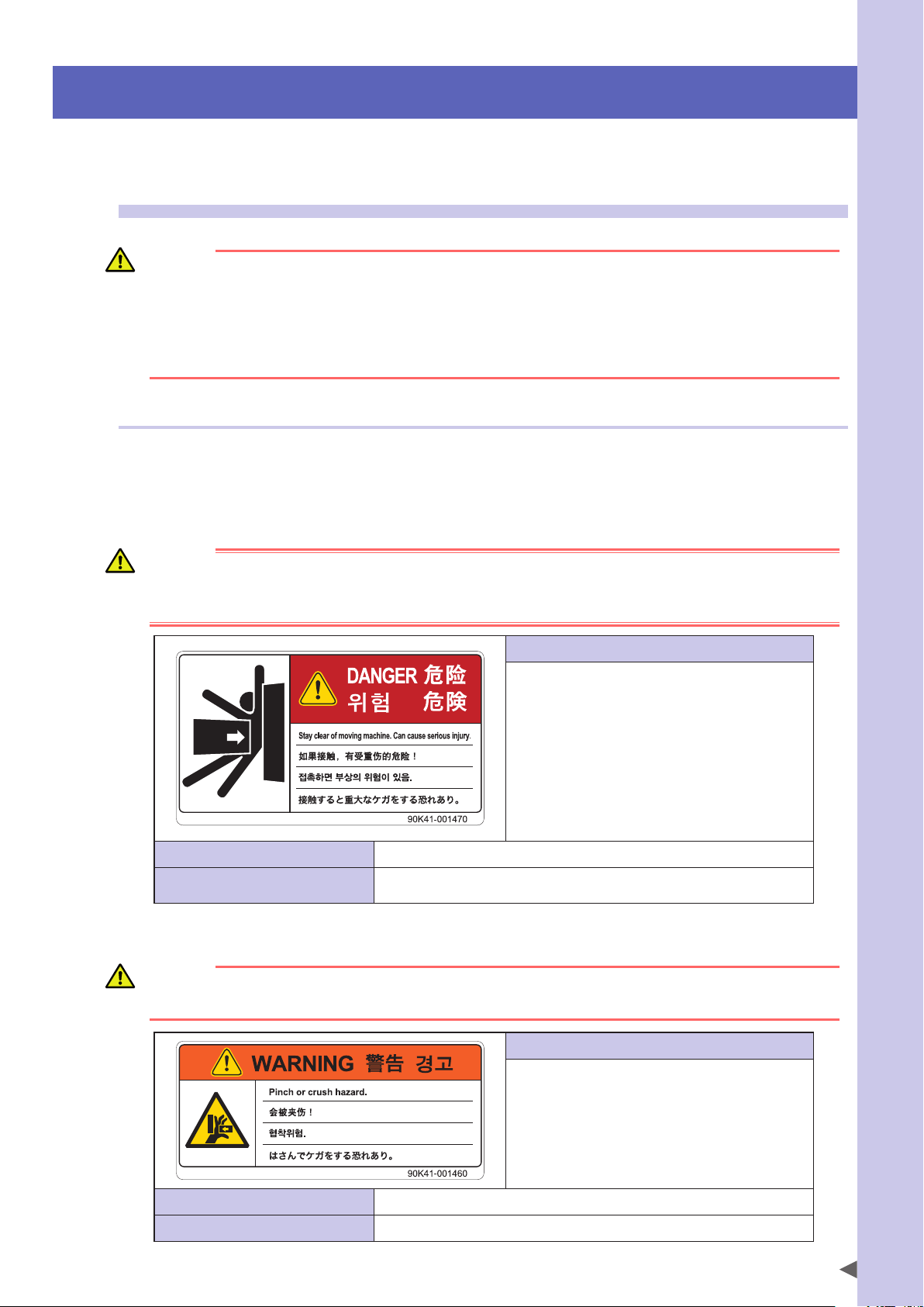
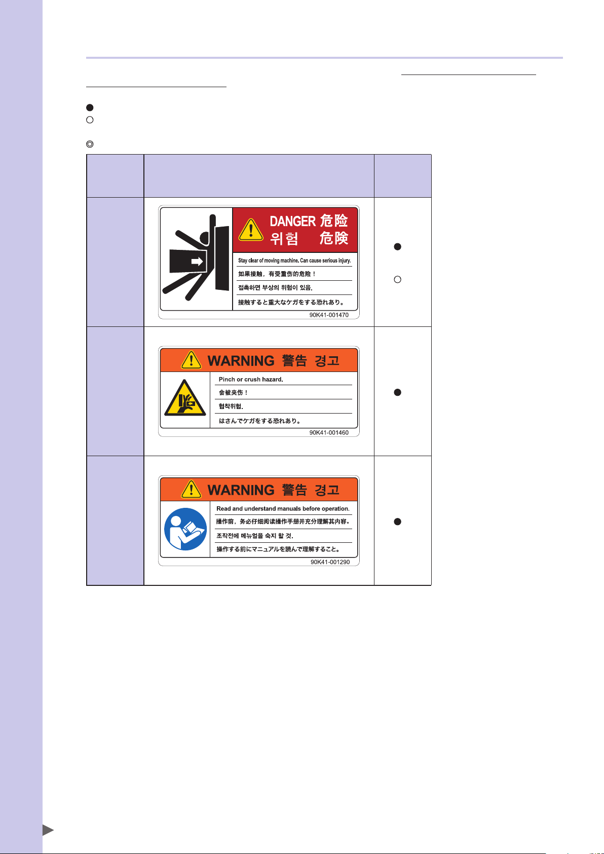
1. Warning label 1 (SCARA robots)
Safety Instructions
DANGER
SERIOUS INJURY MAY RESULT FROM CONTACT WITH A MOVING ROBOT.
• KEEP OUTSIDE OF THE ROBOT SAFETY ENCLOSURE DURING OPERATION.
• PRESS THE EMERGENCY STOP BUTTON BEFORE ENTERING THE SAFETY ENCLOSURE.
• Always install a safety enclosure to keep all persons away
from the robot movement range and prevent injury from
contacting the moving part of the robot.
Install an interlock that triggers emergency stop when the
•
door or gate of the safety enclosure is opened.
• The safety enclosure should be designed so that no one
can enter inside except from the door or gate equipped
with an interlock device.
• Warning label 1 that comes supplied with a robot should
be affixed to an easy-to-see location on the door or gate of
the safety enclosure.
Potential hazard to human body Serious injury may result from contact with a moving robot.
To avoid hazard
• Keep outside of the robot safety enclosure during operation.
• Press the emergency stop button before entering the safety enclosure.
2. Warning label 2 (SCARA robots)
WARNING
MOVING PARTS CAN PINCH OR CRUSH HANDS.
KEEP HANDS AWAY FROM THE MOVABLE PARTS OF THE ROBOT.
Instructions on this label
Instructions on this label
Use caution to prevent hands and fingers from being pinched
or crushed by the movable parts of the robot when
transporting or moving the robot or during teaching.
Potential hazard to human body Moving parts can pinch or crush hands.
To avoid hazard Keep hands away from the movable parts of the robot.
S-3
Page 12
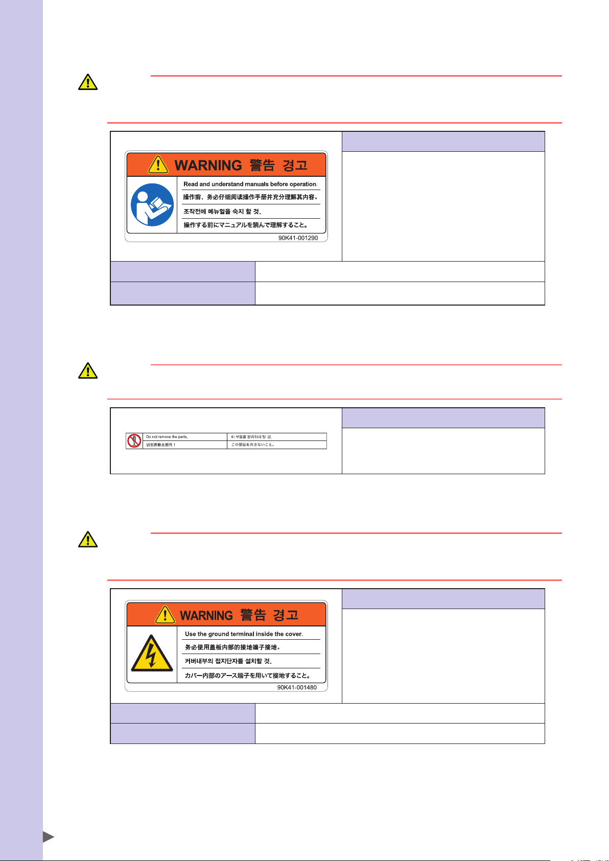
3. Warning label 3 (SCARA robots)
Safety Instructions
WARNING
IMPROPER INSTALLATION OR OPERATION MAY CAUSE SERIOUS INJURY.
BEFORE INSTALLING OR OPERATING THE ROBOT, READ THE MANUAL AND INSTRUCTIONS ON THE WARNING
LABELS AND UNDERSTAND THE CONTENTS.
Instructions on this label
• Be sure to read the warning label and this manual
carefully to make you completely understand the contents
before attempting installation and operation of the robot.
• Before starting the robot operation, even after you have
read through this manual, read again the corresponding
procedures and "Safety instructions" in this manual.
• Never install, adjust, inspect or service the robot in any
manner that does not comply with the instructions in this
manual.
Potential hazard to human body Improper installation or operation may cause serious injury.
To avoid hazard
Before installing or operating the robot, read the manual and instructions on the warning
labels and understand the contents.
4. Warning label 4 (SCARA robots)
CAUTION
Do not remove the parts on which Warning label 4 is attached.
Doing so may damage the ball screw.
5. Warning label 5 (Controller)
WARNING
GROUND THE CONTROLLER TO PREVENT ELECTRICAL SHOCK.
GROUND TERMINAL IS LOCATED INSIDE THIS COVER.
READ THE MANUAL FOR DETAILS.
Potential hazard to human body Electrical shock
Instructions on this label
The Z-axis ball screw will be damaged if the upper end
mechanical stopper on the Z-axis spline is removed or
moved. Never attempt to remove or move it.
Instructions on this label
• High voltage section inside
• To prevent electrical shock, always ground the robot using
the ground terminal located inside the cover.
S-4
To avoid hazard Ground the controller.
Page 13
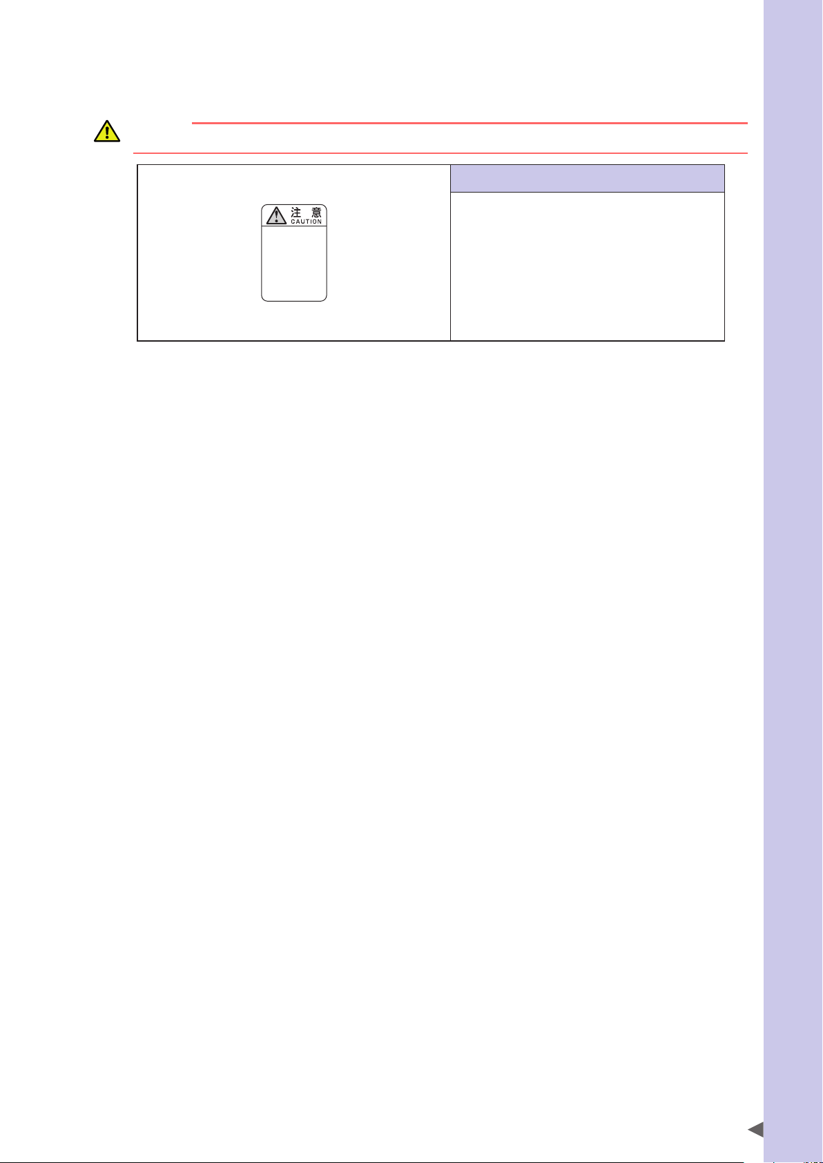
6. "Read instruction manual" label (Controller)*
* This label is attached to the front panel.
CAUTION
Refer to the manual.
取扱説明書参照
READ INSTRUCTION
MANUAL
Safety Instructions
Instructions on this label
This indicates important information that you must know and
is described in the manual.
Before using the controller, be sure to read the manual
thoroughly.
When adding external safety circuits or connecting a power
supply to the controller, read the manual carefully and make
checks before beginning the work.
Connectors have an orientation. Insert each connector in the
correct direction.
S-5
Page 14
3.1.2 Supplied warning labels
Safety Instructions
Some warning labels are not affixed to robots but included in the packing box. These warning labels should be
affixed to an easy-to-see location.
Warning label is attached to the robot body.
Warning label comes supplied with the robot and should be affixed to an easy-to-see location on the door or gate of the safety
enclosure.
Warning label comes supplied with the robot and should be affixed to an easy-to-see location.
SCARA
robots
1
*
Warning label
1
Warning label
2
Warning label
3
*1: See "Part names" in each SCARA robot manual for label positions.
1
*
1
*
S-6
Page 15
3.2 Warning symbols
!
Warning symbols shown below are indicated on the robots and controllers to alert the operator to potential hazards. To
use the OMRON robot safely and correctly always follow the instructions and cautions indicated by the symbols.
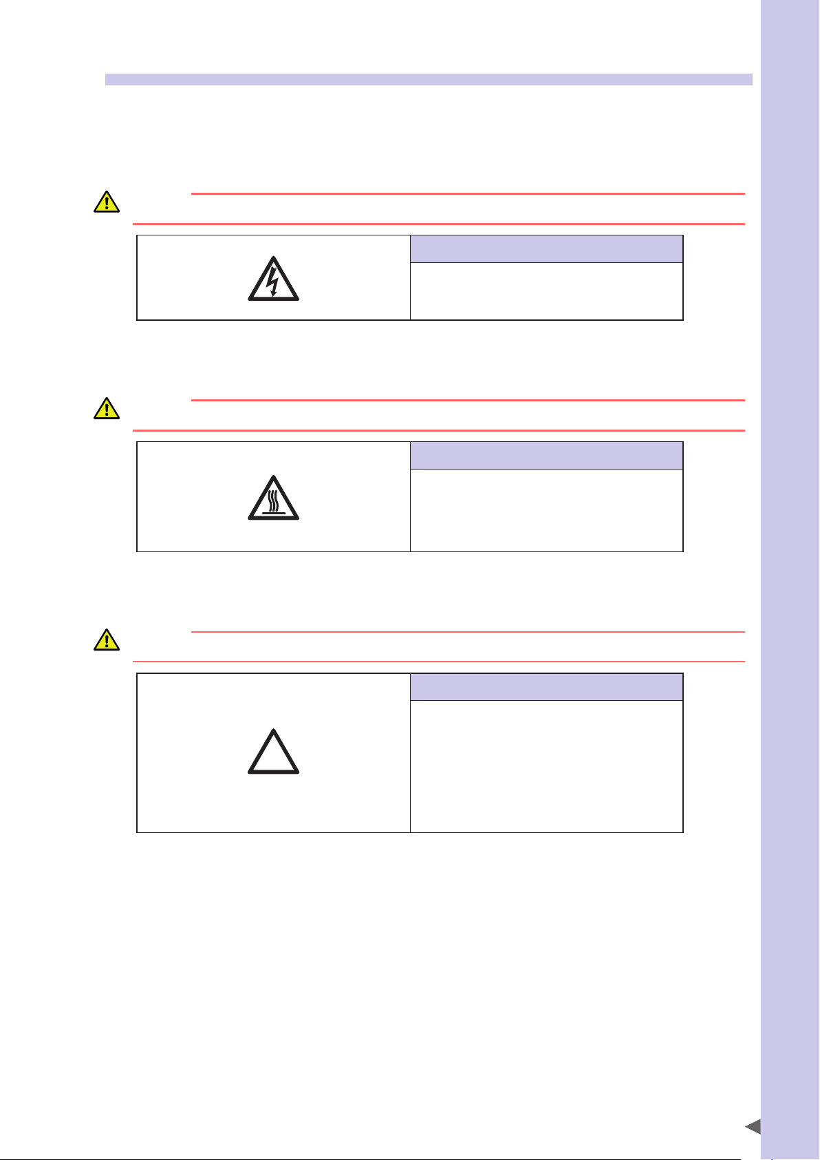
1. Electrical shock hazard symbol
WARNING
TOUCHING THE TERMINAL BLOCK OR CONNECTOR MAY CAUSE ELECTRICAL SHOCK, SO USE CAUTION.
Instructions by this symbol
This indicates a high voltage is present.
Touching the terminal block or connector may cause
electrical shock.
2. High temperature hazard symbol
WARNING
MOTORS, HEATSINKS, AND REGENERATIVE UNITS BECOME HOT, SO DO NOT TOUCH THEM.
Instructions by this symbol
This indicates the area around this symbol may become very
hot.
Motors, heatsinks, and regenerative units become hot during
and shortly after operation. To avoid burns be careful not to
touch those sections.
Safety Instructions
3. Caution symbol
CAUTION
Always read the manual carefully before using the controller.
Instructions by this symbol
This indicates important information that you must know and
is described in the manual.
Before using the controller, be sure to read the manual
thoroughly.
When adding external safety circuits or connecting a power
supply to the controller, read the manual carefully and make
checks before beginning the work.
Connectors must be attached while facing a certain direction,
so insert each connector in the correct direction.
S-7
Page 16

4. Major precautions for each stage of use
Safety Instructions
This section describes major precautions that must be observed when using robots and controllers. Be sure to carefully
read and comply with all of these precautions even if there is no alert symbol shown.
4.1 Precautions for using robots and controllers
General precautions for using robots and controllers are described below.
1. Applications where robots cannot be used
OMRON robots and robot controllers are designed as general-purpose industrial equipment and cannot be used for the following
applications.
DANGER
OMRON ROBOT CONTROLLERS AND ROBOTS ARE DESIGNED AS GENERAL-PURPOSE INDUSTRIAL EQUIPMENT AND
CANNOT BE USED FOR THE FOLLOWING APPLICATIONS.
• IN MEDICAL EQUIPMENT SYSTEMS WHICH ARE CRITICAL TO HUMAN LIFE
• IN SYSTEMS THAT SIGNIFICANTLY AFFECT SOCIETY AND THE GENERAL PUBLIC
• IN EQUIPMENT INTENDED TO CARRY OR TRANSPORT PEOPLE
• IN ENVIRONMENTS WHICH ARE SUBJECT TO VIBRATION SUCH AS ONBOARD SHIPS AND VEHICLES.
2. Qualification of operators/workers
Operators or persons who handle the robot such as for teaching, programming, movement check, inspection, adjustment, and
repair must receive appropriate training and also have the skills needed to perform the job correctly and safely. They must read the
manual carefully to understand its contents before attempting the robot operation or maintenance.
Tasks related to industrial robots (teaching, programming, movement check, inspection, adjustment, repair, etc.) must be
performed by qualified persons who meet requirements established by local regulations and standards for industrial robots.
WARNING
• THE ROBOT MUST BE OPERATED ONLY BY PERSONS WHO HAVE RECEIVED SAFETY AND OPERATION TRAINING.
OPERATION BY AN UNTRAINED PERSON IS EXTREMELY HAZARDOUS.
• ADJUSTMENT AND MAINTENANCE BY REMOVING A COVER REQUIRE SPECIALIZED TECHNICAL KNOWLEDGE
AND SKILLS, AND MAY ALSO INVOLVE HAZARDS IF ATTEMPTED BY AN UNSKILLED PERSON. THESE TASKS
MUST BE PERFORMED ONLY BY PERSONS WHO HAVE ENOUGH ABILITY AND QUALIFICATIONS IN ACCORDANCE
WITH LOCAL LAWS AND REGULATIONS. FOR DETAILED INFORMATION, PLEASE CONTACT YOUR DISTRIBUTOR
WHERE YOU PURCHASED THE PRODUCT.
S-8
Page 17
4.2 Design
4.2.1 Precautions for robots
1. Restricting the robot moving speed
WARNING
RESTRICTION ON THE ROBOT MOVING SPEED IS NOT A SAFETY-RELATED FUNCTION.
TO REDUCE THE RISK OF COLLISION BETWEEN THE ROBOT AND WORKERS, THE USER MUST TAKE THE
NECESSARY PROTECTIVE MEASURES SUCH AS ENABLE DEVICES ACCORDING TO RISK ASSESSMENT BY THE USER.
2. Restricting the movement range
See “7.1 Movement range” in “Safety instructions” for details on the robot’s movement range.
WARNING
SOFT LIMIT FUNCTION IS NOT A SAFETY-RELATED FUNCTION INTENDED TO PROTECT THE HUMAN BODY.
TO RESTRICT THE ROBOT MOVEMENT RANGE TO PROTECT THE HUMAN BODY, USE THE MECHANICAL STOPPERS
INSTALLED IN THE ROBOT (OR AVAILABLE AS OPTIONS).
CAUTION
If the robot moving at high speed collides with a mechanical stopper installed in the robot (or available as option), the robot may be
damaged.
3. Provide safety measures for end effector (gripper, etc.)
Safety Instructions
WARNING
• END EFFECTORS MUST BE DESIGNED AND MANUFACTURED SO THAT THEY CAUSE NO HAZARDS (SUCH AS A
LOOSE WORKPIECE OR LOAD) EVEN IF POWER (ELECTRICITY, AIR PRESSURE, ETC.) IS SHUT OFF OR POWER
FLUCTUATIONS OCCUR.
•
IF THE OBJECT GRIPPED BY THE END EFFECTOR MIGHT POSSIBLY FLY OFF OR DROP, THEN PROVIDE
APPROPRIATE SAFETY PROTECTION TAKING INTO ACCOUNT THE OBJECT SIZE, WEIGHT, TEMPERATURE, AND
CHEMICAL PROPERTIES.
4. Provide adequate lighting
Provide enough lighting to ensure safety during work.
5. Install an operation status light
WARNING
INSTALL A SIGNAL LIGHT (SIGNAL TOWER) AT AN EASY-TO-SEE POSITION SO THAT THE OPERATOR WILL BE AWARE
OF THE ROBOT STOP STATUS (TEMPORARILY STOPPED, EMERGENCY STOP, ERROR STOP, ETC.).
4.2.2 Precautions for robot controllers
1. Emergency stop input terminal
DANGER
EACH ROBOT CONTROLLER HAS AN EMERGENCY STOP INPUT TERMINAL TO TRIGGER EMERGENCY STOP. USING
THIS TERMINAL, INSTALL A SAFETY CIRCUIT SO THAT THE SYSTEM INCLUDING THE ROBOT CONTROLLER WILL
WORK SAFELY.
2. Maintain clearance
CAUTION
Do not bundle control lines or communication cables together or in close to the main power supply or power lines. Usually separate
these by at least 100mm. Failure to follow this instruction may cause malfunction due to noise.
S-9
Page 18
4.3 Moving and installation
Safety Instructions
4.3.1 Precautions for robots
■Installation environment
1. Do not use in strong magnetic fields
WARNING
DO NOT USE THE ROBOT NEAR EQUIPMENT OR IN LOCATIONS THAT GENERATE STRONG MAGNETIC FIELDS. THE
ROBOT MAY BREAK DOWN OR MALFUNCTION IF USED IN SUCH LOCATIONS.
2. Do not use in locations subject to possible electromagnetic interference, etc.
WARNING
DO NOT USE THE ROBOT IN LOCATIONS SUBJECT TO ELECTROMAGNETIC INTERFERENCE, ELECTROSTATIC
DISCHARGE OR RADIO FREQUENCY INTERFERENCE. THE ROBOT MAY MALFUNCTION IF USED IN SUCH LOCATIONS
CREATING HAZARDOUS SITUATIONS.
3. Do not use in locations exposed to flammable gases
WARNING
• OMRON ROBOTS ARE NOT DESIGNED TO BE EXPLOSION-PROOF.
• DO NOT USE THE ROBOTS IN LOCATIONS EXPOSED TO EXPLOSIVE OR INFLAMMABLE GASES, DUST PARTICLES
OR LIQUID. FAILURE TO FOLLOW THIS INSTRUCTION MAY CAUSE SERIOUS ACCIDENTS INVOLVING INJURY OR
DEATH, OR LEAD TO FIRE.
■Moving
1. Use caution to prevent pinching or crushing of hands or fingers
WARNING
MOVING PARTS CAN PINCH OR CRUSH HANDS OR FINGERS.
KEEP HANDS AWAY FROM THE MOVABLE PARTS OF THE ROBOT.
As instructed in Warning label 2, use caution to prevent hands or fingers from being pinched or crushed by movable parts when
transporting or moving the robot. For details on warning labels, see "3. Warning labels" in "Safety instructions."
2. Take safety measures when moving the robot
To ensure safety when moving a SCARA robot with an arm length of 500mm or more, use the eyebolts that come supplied with
the robot.
Refer to the Robot Manual for details.
■Installation
1. Protect electrical wiring and hydraulic/pneumatic hoses
Install a cover or similar item to protect the electrical wiring and hydraulic/pneumatic hoses from possible damage.
■Wiring
1. Protective measures against electrical shock
WARNING
ALWAYS GROUND THE ROBOT TO PREVENT ELECTRICAL SHOCK.
S-10
Page 19
■Adjustment
1. Adjustment that requires removing a cover
WARNING
ADJUSTMENT BY REMOVING A COVER REQUIRE SPECIALIZED TECHNICAL KNOWLEDGE AND SKILLS, AND MAY
ALSO INVOLVE HAZARDS IF ATEMPTED BY AN UNSKILLED PERSON. THESE TASKS MUST BE PERFORMED ONLY BY
PERSONS WHO HAVE ENOUGH ABILITY AND QUALIFICATIONS IN ACORDANCE WITH LOCAL LAWS AND
REGULATIONS. FOR DETAILED INFORMATION, PLEASE CONTACT YOUR DISTRIBUTOR WHERE YOU PURCHASED
THE PRODUCT.
4.3.2 Precautions for robot controllers
■Installation environment
1. Installation environment
WARNING
OMRON ROBOTS ARE NOT DESIGNED TO BE EXPLOSION-PROOF. DO NOT USE THE ROBOTS AND CONTROLLERS IN
LOCATIONS EXPOSED TO EXPLOSIVE OR INFLAMMABLE GASES, DUST PARTICLES OR LIQUID SUCH AS GASOLINE
AND SOLVENTS. FAILURE TO FOLLOW THIS INSTRUCTION MAY CAUSE SERIOUS ACCIDENTS INVOLVING INJURY
OR DEATH, AND LEAD TO FIRE.
WARNING
• USE THE ROBOT CONTROLLER IN LOCATIONS THAT SUPPORT THE ENVIRONMENTAL CONDITIONS SPECIFIED IN
THIS MANUAL. OPERATION OUTSIDE THE SPECIFIED ENVIRONMENTAL RANGE MAY CAUSE ELECTRICAL SHOCK,
FIRE, MALFUNCTION OR PRODUCT DAMAGE OR DETERIORATION.
• THE ROBOT CONTROLLER AND PROGRAMMING BOX MUST BE INSTALLED AT A LOCATION THAT IS OUTSIDE THE
ROBOT SAFETY ENCLOSURE YET WHERE IT IS EASY TO OPERATE AND VIEW ROBOT MOVEMENT.
• INSTALL THE ROBOT CONTROLLER IN LOCATIONS WITH ENOUGH SPACE TO PERFORM WORK (TEACHING,
INSPECTION, ETC.) SAFELY. LIMITED SPACE NOT ONLY MAKES IT DIFFICULT TO PERFORM WORK BUT CAN ALSO
CAUSE INJURY.
• INSTALL THE ROBOT CONTROLLER IN A STABLE, LEVEL LOCATION AND SECURE IT FIRMLY. AVOID INSTALLING
THE CONTROLLER UPSIDE DOWN OR IN A TILTED POSITION.
• PROVIDE SUFFICIENT CLEARANCE AROUND THE ROBOT CONTROLLER FOR GOOD VENTILATION. INSUFFICIENT
CLEARANCE MAY CAUSE MALFUNCTION, BREAKDOWN OR FIRE.
Safety Instructions
■Installation
To install the robot controller, observe the installation conditions and method described in the manual.
1. Installation
WARNING
SECURELY TIGHTEN THE SCREWS FOR THE L-SHAPED BRACKETS USED TO INSTALL THE ROBOT CONTROLLER. IF
NOT SECURELY TIGHTENED, THE SCREWS MAY COME LOOSE CAUSING THE CONTROLLER TO DROP.
2. Connections
WARNING
• ALWAYS SHUT OFF ALL PHASES OF THE POWER SUPPLY EXTERNALLY BEFORE STARTING INSTALLATION OR
WIRING WORK. FAILURE TO DO THIS MAY CAUSE ELECTRICAL SHOCK OR PRODUCT DAMAGE.
• NEVER DIRECTLY TOUCH CONDUCTIVE SECTIONS AND ELECTRONIC PARTS OTHER THAN THE CONNECTORS,
ROTARY SWITCHES, AND DIP SWITCHES ON THE OUTSIDE PANEL OF THE ROBOT CONTROLLER. TOUCHING
THEM MAY CAUSE ELECTRICAL SHOCK OR BREAKDOWN.
• SECURELY INSTALL EACH CABLE CONNECTOR INTO THE RECEPTACLES OR SOCKETS. POOR CONNECTIONS MAY
CAUSE THE CONTROLLER OR ROBOT TO MALFUNCTION.
S-11
Page 20
■Wiring
Safety Instructions
1. Connection to robot controller
The controller parameters are preset at the factory before shipping to match the robot model. Check the specified robot and
controller combination, and connect them in the correct combination.
Since the software detects abnormal operation such as motor overloads, the controller parameters must be set correctly to match
the motor type used in the robot connected to the controller.
2. Wiring safety points
WARNING
ALWAYS SHUT OFF ALL PHASES OF THE POWER SUPPLY EXTERNALLY BEFORE STARTING INSTALLATION OR
WIRING WORK. FAILURE TO DO THIS MAY CAUSE ELECTRICAL SHOCK OR PRODUCT DAMAGE.
CAUTION
• Makesurethatnoforeignmattersuchascuttingchipsorwirescrapsgetintotherobotcontroller.Malfunction,breakdownorre
may result if these penetrate inside.
• Do not apply excessive impacts or loads to the connectors when making cable connections. This might bend the connector pins or
damage the internal PC board.
• Whenusingferritecoresfornoiseelimination,besuretotthemontothepowercableasclosetotherobotcontrollerand/orthe
robot as possible, to prevent malfunction caused by noise.
3. Wiring method
WARNING
SECURELY INSTALL THE CONNECTORS INTO THE ROBOT CONTROLLER AND, WHEN WIRING THE CONNECTORS,
MAKE THE CRIMP, PRESS-CONTACT OR SOLDER CONNECTIONS CORRECTLY USING THE TOOL SPECIFIED BY THE
CONNECTOR MANUFACTURER.
CAUTION
When disconnecting the cable from the robot controller, detach by gripping the connector itself and not by tugging on the cable. Loosen
the screws on the connector (if fastened with the screws), and then disconnect the cable. Trying to detach by pulling on the cable itself
may damage the connector or cables, and poor cable contact will cause the controller or robot to malfunction.
4. Precautions for cable routing and installation
CAUTION
• Always store the cables connected to the robot controller in a conduit or clamp them securely in place. If the cables are not stored in
a conduit or properly clamped, excessive play or movement or mistakenly pulling on the cable may damage the connector or cables,
and poor cable contact will cause the controller or robot to malfunction.
• Do not modify the cables and do not place any heavy objects on them. Handle them carefully to avoid damage. Damaged cables may
cause malfunction or electrical shock.
• If the cables connected to the robot controller may possibly become damaged, then protect them with a cover, etc.
• Checkthatthecontrollinesandcommunicationcablesareroutedatagapsufcientlyawayfrommainpowersupplycircuitsand
power lines, etc. Bundling them together with power lines or close to power lines may cause faulty operation due to noise.
5. Protective measures against electrical shock
WARNING
BE SURE TO GROUND THE CONTROLLER USING THE GROUND TERMINAL ON THE POWER TERMINAL BLOCK. POOR
GROUNDING MAY CAUSE ELECTRICAL SHOCK.
S-12
Page 21
4.4 Safety measures
4.4.1 Safety measures
1. Referring to warning labels and manual
WARNING
• BEFORE STARTING INSTALLATION OR OPERATION OF THE ROBOT, BE SURE TO READ THE WARNING LABELS
AND THIS MANUAL, AND COMPLY WITH THE INSTRUCTIONS.
• NEVER ATTEMPT ANY REPAIR, PARTS REPLACEMENT AND MODIFICATION UNLESS DESCRIBED IN THIS MANUAL.
THESE TASKS REQUIRE SPECIALIZED TECHNICAL KNOWLEDGE AND SKILLS AND MAY ALSO INVOLVE
HAZARDS. PLEASE CONTACT YOUR DISTRIBUTOR FOR ADVICE.
NOTE
For details on warning labels, see "3. Warning labels" in "Safety instructions."
2. Draw up "work instructions" and make the operators/workers understand them
WARNING
DECIDE ON "WORK INSTRUCTIONS" IN CASES WHERE PERSONNEL MUST WORK WITHIN THE ROBOT SAFETY
ENCLOSURE TO PERFORM STARTUP OR MAINTENANCE WORK. MAKE SURE THE WORKERS COMPLETELY
UNDERSTAND THESE "WORK INSTRUCTIONS".
Decide on "work instructions" for the following items in cases where personnel must work within the robot safety enclosure to
perform teaching, maintenance or inspection tasks. Make sure the workers completely understand these "work instructions".
1. Robot operating procedures needed for tasks such as startup procedures and handling switches
2. Robot speeds used during tasks such as teaching
3. Methods for workers to signal each other when two or more workers perform tasks
4. Steps that the worker should take when a problem or emergency occurs
5. Steps to take after the robot has come to a stop when the emergency stop device was triggered, including checks for cancelling
the problem or error state and safety checks in order to restart the robot.
6. In cases other than above, the following actions should be taken as needed to prevent hazardous situations due to sudden or
unexpected robot operation or faulty robot operation as listed below.
• Place a display sign on the operator panel
• Ensure the safety of workers performing tasks within the robot safety enclosure
• Clearly specify position and posture during work
Specify a position and posture where worker can constantly check robot movements and immediately move to avoid
trouble if an error/problem occurs
• Take noise prevention measures
• Use methods for signaling operators of related equipment
• Use methods to decide that an error has occurred and identify the type of error
Implement the "work instructions" according to the type of robot, installation location, and type of work task.
When drawing up the "work instructions", make an effort to include opinions from the workers involved, equipment manufacturer
technicians, and workplace safety consultants, etc.
Safety Instructions
3. Take safety measures
DANGER
• NEVER ENTER THE ROBOT MOVEMENT RANGE WHILE THE ROBOT IS OPERATING OR THE MAIN POWER IS
TURNED ON. FAILURE TO FOLLOW THIS WARNING MAY CAUSE SERIOUS ACCIDENTS INVOLVING INJURY OR
DEATH. INSTALL A SAFETY ENCLOSURE OR A GATE INTERLOCK WITH AN AREA SENSOR TO KEEP ALL PERSONS
AWAY FROM THE ROBOT MOVEMENT RANGE.
• WHEN IT IS NECESSARY TO OPERATE THE ROBOT WHILE YOU ARE WITHIN THE ROBOT MOVEMENT RANGE
SUCH AS FOR TEACHING OR MAINTENANCE/INSPECTION TASKS, ALWAYS CARRY THE PROGRAMMING BOX
WITH YOU SO THAT YOU CAN IMMEDIATELY STOP THE ROBOT OPERATION IN CASE OF AN ABNORMAL OR
HAZARDOUS CONDITION. INSTALL AN ENABLE DEVICE IN THE EXTERNAL SAFETY CIRCUIT AS NEEDED. ALSO
SET THE ROBOT MOVING SPEED TO 3% OR LESS. FAILURE TO FOLLOW THESE INSTRUCTIONS MAY CAUSE
SERIOUS ACCIDENTS INVOLVING INJURY OR DEATH.
See “7.1 Movement range” in “Safety instructions” for details on the robot’s movement range.
S-13
Page 22

Safety Instructions
WARNING
• DURING STARTUP OR MAINTENANCE TASKS, DISPLAY A SIGN "WORK IN PROGRESS" ON THE PROGRAMMING
BOX AND OPERATION PANEL IN ORDER TO PREVENT ANYONE OTHER THAN THE PERSON FOR THAT TASK FROM
MISTAKENLY OPERATING THE START OR SELECTOR SWITCH. IF NEEDED, TAKE OTHER MEASURES SUCH AS
LOCKING THE COVER ON THE OPERATION PANEL.
• ALWAYS CONNECT THE ROBOT AND ROBOT CONTROLLER IN THE CORRECT COMBINATION. USING THEM IN AN
INCORRECT COMBINATION MAY CAUSE FIRE OR BREAKDOWN.
4. Install system
When configuring an automated system using a robot, hazardous situations are more likely to occur from the automated system
than the robot itself. So the system manufacturer should install the necessary safety measures required for the individual system.
The system manufacturer should provide a proper manual for safe, correct operation and servicing of the system.
WARNING
TO CHECK THE ROBOT CONTROLLER OPERATING STATUS, REFER TO THIS MANUAL AND TO RELATED MANUALS.
DESIGN AND INSTALL THE SYSTEM INCLUDING THE ROBOT CONTROLLER SO THAT IT WILL ALWAYS WORK
SAFELY.
5. Precautions for operation
WARNING
• DO NOT TOUCH ANY ELECTRICAL TERMINAL. DIRECTLY TOUCHING THESE TERMINALS MAY CAUSE
ELECTRICAL SHOCK, EQUIPMENT DAMAGE, AND MALFUNCTION.
• DO NOT TOUCH OR OPERATE THE ROBOT CONTROLLER OR PROGRAMMING BOX WITH WET HANDS. TOUCHING
OR OPERATING THEM WITH WET HANDS MAY RESULT IN ELECTRICAL SHOCK OR BREAKDOWN.
6. Do not disassemble and modify
WARNING
NEVER DISASSEMBLE AND MODIFY ANY PART IN THE ROBOT, CONTROLLER, AND PROGRAMMING BOX. DO NOT
OPEN ANY COVER. DOING SO MAY CAUSE ELECTRICAL SHOCK, BREAKDOWN, MALFUNCTION, INJURY, OR FIRE.
4.4.2 Installing a safety enclosure
Be sure to install a safety enclosure to keep anyone from entering within the movement range of the robot. The safety
enclosure will prevent the operator and other persons from coming in contact with moving parts of the robot and
suffering injury.
See “7.1 Movement range” in “Safety instructions” for details on the robot’s movement range.
DANGER
SERIOUS INJURY MAY RESULT FROM CONTACT WITH A MOVING ROBOT.
• KEEP OUTSIDE OF THE ROBOT SAFETY ENCLOSURE DURING OPERATION.
• PRESS THE EMERGENCY STOP BUTTON BEFORE ENTERING THE SAFETY ENCLOSURE.
WARNING
• INSTALL AN INTERLOCK THAT TRIGGERS EMERGENCY STOP WHEN THE DOOR OR GATE OF THE SAFETY
ENCLOSURE IS OPENED.
• THE SAFETY ENCLOSURE SHOULD BE DESIGNED SO THAT NO ONE CAN ENTER INSIDE EXCEPT FROM THE DOOR
OR GATE EQUIPPED WITH AN INTERLOCK DEVICE.
• WARNING LABEL 1 (SEE "3. WARNING LABELS" IN "SAFETY INSTRUCTIONS") THAT COMES SUPPLIED WITH A
ROBOT SHOULD BE AFFIXED TO AN EASY-TO-SEE LOCATION ON THE DOOR OR GATE OF THE SAFETY
ENCLOSURE.
S-14
Page 23
4.5 Operation
When operating a robot, ignoring safety measures and checks may lead to serious accidents. Always take the following
safety measures and checks to ensure safe operation.
DANGER
CHECK THE FOLLOWING POINTS BEFORE STARTING ROBOT OPERATION.
• NO ONE IS WITHIN THE ROBOT SAFETY ENCLOSURE.
• THE PROGRAMMING UNIT IS IN THE SPECIFIED LOCATION.
• THE ROBOT AND PERIPHERAL EQUIPMENT ARE IN GOOD CONDITION.
4.5.1 Trial operation
After installing, adjusting, inspecting, maintaining or repairing the robot, perform trial operation using the following
procedures.
1. If a safety enclosure has not yet been provided right after installing the robot:
Then rope off or chain off the movement range around the robot in place of the safety enclosure and observe the following points.
See “7.1 Movement range” in “Safety instructions” for details on the robot’s movement range.
DANGER
PLACE A "ROBOT IS MOVING - KEEP AWAY!" SIGN TO KEEP THE OPERATOR OR OTHER PERSONNEL FROM ENTERING
WITHIN THE MOVEMENT RANGE OF THE ROBOT.
Safety Instructions
WARNING
• USE STURDY, STABLE POSTS WHICH WILL NOT FALL OVER EASILY.
• THE ROPE OR CHAIN SHOULD BE EASILY VISIBLE TO EVERYONE AROUND THE ROBOT.
2. Check the following points before turning on the controller.
• Is the robot securely and correctly installed?
• Are the electrical connections to the robot wired correctly?
• Are items such as air pressure correctly supplied?
• Is the robot correctly connected to peripheral equipment?
• Have safety measures (safety enclosure, etc.) been taken?
• Does the installation environment meet the specified standards?
3. After the controller is turned on, check the following points from outside the safety enclosure.
• Does the robot start, stop and enter the selected operation mode as intended?
• Does each axis move as intended within the soft limits?
• Does the end effector move as intended?
• Are the correct signals being sent to the end effector and peripheral equipment?
• Does emergency stop function?
• Are teaching and playback functions normal?
• Are the safety enclosure and interlocks functioning as intended?
S-15
Page 24
4. Working inside safety enclosures
Safety Instructions
Before starting work within the safety enclosure, always confirm from outside the enclosure that each protective function is
operating correctly (see the previous section 2.3).
DANGER
NEVER ENTER WITHIN THE MOVEMENT RANGE WHILE WITHIN THE SAFETY ENCLOSURE.
See “7.1 Movement range” in “Safety instructions” for details on the robot’s movement range.
WARNING
WHEN WORK IS REQUIRED WITHIN THE SAFETY ENCLOSURE, PLACE A SIGN "WORK IN PROGRESS" IN ORDER TO
KEEP OTHER PERSONS FROM OPERATING THE CONTROLLER SWITCH OR OPERATION PANEL.
WARNING
WHEN WORK WITHIN THE SAFETY ENCLOSURE IS REQUIRED, ALWAYS TURN OFF THE CONTROLLER POWER
EXCEPT FOR THE FOLLOWING CASES:
Exception
Work with power turned on, but robot in emergency stop
Origin position setting SCARA robots
Standard coordinate setting SCARA robots
Soft limit settings SCARA robots
Follow the precautions and procedure described in "2. Adjusting the origin"
in Chapter 3.
Follow the precautions and procedure described in "4. Setting the standard
coordinates" in Chapter 3.
Follow the precautions and procedure described in "3. Setting the soft
limits" in Chapter 3.
Work with power turned on
Teaching SCARA robots Refer to "5. Teaching within safety enclosure" described below.
5. Teaching within the safety enclosure
When performing teaching within the safety enclosure, check or perform the following points from outside the safety enclosure.
DANGER
NEVER ENTER WITHIN THE MOVEMENT RANGE WHILE WITHIN THE SAFETY ENCLOSURE.
See “7.1 Movement range” in “Safety instructions” for details on the robot’s movement range.
WARNING
• MAKE A VISUAL CHECK TO ENSURE THAT NO HAZARDS ARE PRESENT WITHIN THE SAFETY ENCLOSURE.
• CHECK THAT THE PROGRAMMING BOX OR HANDY TERMINAL OPERATES CORRECTLY.
• CHECK THAT NO FAILURES ARE FOUND IN THE ROBOT.
• CHECK THAT EMERGENCY STOP WORKS CORRECTLY.
• SELECT TEACHING MODE AND DISABLE AUTOMATIC OPERATION.
S-16
Page 25
4.5.2 Automatic operation
Check the following points when operating the robot in AUTO mode. Observe the instructions below in cases where an
error occurs during automatic operation. Automatic operation described here includes all operations in AUTO mode.
1. Checkpoints before starting automatic operation
Check the following points before starting automatic operation
DANGER
• CHECK THAT NO ONE IS WITHIN THE SAFETY ENCLOSURE.
• CHECK THE SAFETY ENCLOSURE IS SECURELY INSTALLED WITH INTERLOCKS FUNCTIONAL.
WARNING
• CHECK THAT THE PROGRAMMING BOX / HANDY TERMINAL AND TOOLS ARE IN THEIR SPECIFIED LOCATIONS.
• CHECK THAT THE SIGNAL TOWER LAMPS OR OTHER ALARM DISPLAYS INSTALLED FOR THE SYSTEM ARE NOT
LIT OR FLASHING, INDICATING NO ERROR IS OCCURRING ON THE ROBOT AND PERIPHERAL DEVICES.
2. During automatic operation and when errors occur
After automatic operation starts, check the operation status and the signal tower to ensure that the robot is in automatic operation.
DANGER
NEVER ENTER THE SAFETY ENCLOSURE DURING AUTOMATIC OPERATION.
WARNING
IF AN ERROR OCCURS IN THE ROBOT OR PERIPHERAL EQUIPMENT, OBSERVE THE FOLLOWING PROCEDURE
BEFORE ENTERING THE SAFETY ENCLOSURE.
1) PRESS THE EMERGENCY STOP BUTTON TO SET THE ROBOT TO EMERGENCY STOP.
2) PLACE A SIGN ON THE START SWITCH, INDICATING THAT THE ROBOT IS BEING INSPECTED IN ORDER TO KEEP
OTHER PERSONS FROM RESTARTING THE ROBOT.
Safety Instructions
4.5.3 Precautions during operation
1. When the robot is damaged or an abnormal condition occurs
WARNING
• IF UNUSUAL ODORS, NOISE OR SMOKE OCCUR DURING OPERATION, IMMEDIATELY TURN OFF POWER TO
PREVENT POSSIBLE ELECTRICAL SHOCK, FIRE OR BREAKDOWN. STOP USING THE ROBOT AND CONTACT YOUR
DISTRIBUTOR.
• IF ANY OF THE FOLLOWING DAMAGE OR ABNORMAL CONDITIONS OCCURS THE ROBOT, THEN CONTINUING TO
OPERATE THE ROBOT IS DANGEROUS. IMMEDIATELY STOP USING THE ROBOT AND CONTACT YOUR
DISTRIBUTOR.
Damage or abnormal condition Type of danger
Damage to machine harness or robot cable Electrical shock, robot malfunction
Damage to robot exterior Damaged parts fly off during robot operation
Abnormal robot operation (position deviation, vibration, etc.) Robot malfunction
Z-axis (vertical axis) or brake malfunction Loads fall off
2. High temperature hazard
WARNING
• DO NOT TOUCH THE ROBOT CONTROLLER AND ROBOT DURING OPERATION. THE ROBOT CONTROLLER AND
ROBOT BODY ARE VERY HOT DURING OPERATION, SO BURNS MAY OCCUR IF THESE SECTIONS ARE TOUCHED.
• THE MOTOR AND SPEED REDUCTION GEAR CASING ARE VERY HOT SHORTLY AFTER OPERATION, SO BURNS MAY
OCCUR IF THESE ARE TOUCHED. BEFORE TOUCHING THOSE PARTS FOR INSPECTIONS OR SERVICING, TURN OFF
THE CONTROLLER, WAIT FOR A WHILE AND CHECK THAT THEIR TEMPERATURE HAS COOLED.
S-17
Page 26

3. Use caution when releasing the Z-axis (vertical axis) brake
Safety Instructions
WARNING
THE VERTICAL AXIS WILL SLIDE DOWNWARD WHEN THE BRAKE IS RELEASED, CAUSING A HAZARDOUS
SITUATION. TAKE ADEQUATE SAFETY MEASURES IN CONSIDERATION BY TAKING THE WEIGHT AND SHAPE INTO
ACCOUNT.
• BEFORE RELEASING THE BRAKE AFTER PRESSING THE EMERGENCY STOP BUTTON, PLACE A SUPPORT UNDER
THE VERTICAL AXIS SO THAT IT WILL NOT SLIDE DOWN.
• BE CAREFUL NOT TO LET YOUR BODY GET CAUGHT BETWEEN THE VERTICAL AXIS AND THE INSTALLATION
BASE WHEN PERFORMING TASKS (DIRECT TEACHING, ETC.) WITH THE BRAKE RELEASED.
4. Be careful of Z-axis movement when the controller is turned off or emergency stop is triggered
(air-driven Z-axis)
WARNING
THE Z-AXIS STARTS MOVING UPWARD WHEN POWER TO THE CONTROLLER OR PLC IS TURNED OFF, THE PROGRAM
IS RESET, EMERGENCY STOP IS TRIGGERED, OR AIR IS SUPPLIED TO THE SOLENOID VALVE FOR THE Z-AXIS AIR
CYLINDER.
• DO NOT LET HANDS OR FINGERS GET CAUGHT AND SQUEEZED BY ROBOT PARTS MOVING ALONG THE Z-AXIS.
• KEEP THE USUAL ROBOT POSITION IN MIND SO AS TO PREVENT THE Z-AXIS FROM HANGING UP OR BINDING ON
OBSTACLES DURING RAISING OF THE Z-AXIS EXCEPT IN CASE OF EMERGENCY STOP.
5. Take protective measures when the Z-axis interferes with peripheral equipment (air-driven Z-axis)
WARNING
WHEN THE Z-AXIS COMES TO A STOP DUE TO OBSTRUCTION FROM PERIPHERAL EQUIPMENT, THE Z-AXIS MAY
MOVE SUDDENLY AFTER THE OBSTRUCTION IS REMOVED, CAUSING INJURY SUCH AS PINCHED OR CRUSHED
HANDS.
• TURN OFF THE CONTROLLER AND REDUCE THE AIR PRESSURE BEFORE ATTEMPTING TO REMOVE THE
OBSTRUCTION.
• BEFORE REDUCING THE AIR PRESSURE, PLACE A SUPPORT UNDER THE Z-AXIS BECAUSE THE Z-AXIS WILL DROP
UNDER ITS OWN WEIGHT.
6. Be careful of Z-axis movement when air supply is stopped (air-driven Z-axis)
WARNING
THE Z-AXIS WILL SLIDE DOWNWARD WHEN THE AIR PRESSURE TO THE Z-AXIS AIR CYLINDER SOLENOID VALVE IS
REDUCED, CREATING A HAZARDOUS SITUATION.
TURN OFF THE CONTROLLER AND PLACE A SUPPORT UNDER THE Z-AXIS BEFORE CUTTING OFF THE AIR SUPPLY.
7. Make correct parameter settings
CAUTION
Therobotmustbeoperatedwiththecorrecttolerablemomentofinertiaandaccelerationcoefcientsthatmatchthemanipulatortip
mass and moment of inertia. Failure to follow this instruction will lead to a premature end to the drive unit service life, damage to robot
parts, or cause residual vibration during positioning.
8. If the X-axis, Y-axis or R-axis rotation angle is small
CAUTION
If the X-axis, Y-axis or R-axis rotation angle is set smaller than 5 degrees, then it will always move within the same position. This
restrictedpositionmakesitdifcultforanoillmtoformonthejointsupportbearing,andsomaypossiblydamagethebearing.Inthis
type of operation, add a range of motion so that the joint moves through 90 degrees or more, about 5 times a day.
S-18
Page 27

4.6 Inspection and maintenance
Always perform daily and periodic inspections and make a pre-operation check to ensure there are no problems with
the robot and related equipment. If a problem or abnormality is found, then promptly repair it or take other measures as
necessary.
Keep a record of periodic inspections or repairs and store this record for at least 3 years.
4.6.1 Before inspection and maintenance work
1. Do not attempt any work or operation unless described in this manual.
Never attempt any work or operation unless described in this manual.
If an abnormal condition occurs, please be sure to contact your distributor. Our service personnel will take appropriate action.
WARNING
NEVER ATTEMPT INSPECTION, MAINTENANCE, REPAIR, AND PART REPLACEMENT UNLESS DESCRIBED IN THIS
MANUAL. THESE TASKS REQUIRE SPECIALIZED TECHNICAL KNOWLEDGE AND SKILLS AND MAY ALSO INVOLVE
HAZARDS. PLEASE BE SURE TO CONTACT YOUR DISTRIBUTOR FOR ADVICE.
2. Precautions during repair and parts replacement
WARNING
WHEN IT IS NECESSARY TO REPAIR OR REPLACE PARTS OF THE ROBOT OR CONTROLLER, PLEASE BE SURE TO
CONTACT YOUR DISTRIBUTOR AND FOLLOW THE INSTRUCTIONS THEY PROVIDE. INSPECTION AND MAINTENANCE
OF THE ROBOT OR CONTROLLER BY AN UNSKILLED, UNTRAINED PERSON IS EXTREMELY HAZARDOUS.
Safety Instructions
Adjustment, maintenance and parts replacement require specialized technical knowledge and skills, and also may involve hazards.
These tasks must be performed only by persons who have enough ability and qualifications required by local laws and regulations.
WARNING
ADJUSTMENT AND MAINTENANCE BY REMOVING A COVER REQUIRE SPECIALIZED TECHNICAL KNOWLEDGE AND
SKILLS, AND MAY ALSO INVOLVE HAZARDS IF ATTEMPTED BY AN UNSKILLED PERSON. FOR DETAILED
INFORMATION, PLEASE CONTACT YOUR DISTRIBUTOR WHERE YOU PURCHASED THE PRODUCT.
3. Shut off all phases of power supply
WARNING
ALWAYS SHUT OFF ALL PHASES OF THE POWER SUPPLY EXTERNALLY BEFORE CLEANING THE ROBOT AND
CONTROLLER OR SECURELY TIGHTENING THE TERMINAL SCREWS ETC. FAILURE TO DO THIS MAY CAUSE
ELECTRICAL SHOCK OR PRODUCT DAMAGE OR MALFUNCTION.
4. Allow a waiting time after power is shut off (Allow time for temperature and voltage to drop)
WARNING
• WHEN PERFORMING MAINTENANCE OR INSPECTION OF THE ROBOT CONTROLLER UNDER YOUR DISTRIBUTOR'S
INSTRUCTIONS, WAIT AT LEAST THE TIME SPECIFIED FOR EACH CONTROLLER AFTER TURNING THE POWER OFF.
SOME COMPONENTS IN THE ROBOT CONTROLLER ARE VERY HOT OR STILL RETAIN A HIGH VOLTAGE SHORTLY
AFTER OPERATION, SO BURNS OR ELECTRICAL SHOCK MAY OCCUR IF THOSE PARTS ARE TOUCHED.
• THE MOTOR AND SPEED REDUCTION GEAR CASING ARE VERY HOT SHORTLY AFTER OPERATION, SO BURNS MAY
OCCUR IF THEY ARE TOUCHED. BEFORE TOUCHING THOSE PARTS FOR INSPECTIONS OR SERVICING, TURN OFF
THE CONTROLLER, WAIT FOR A WHILE AND CHECK THAT THE TEMPERATURE HAS COOLED.
5. Precautions during inspection of controller
WARNING
• WHEN YOU NEED TO TOUCH THE TERMINALS OR CONNECTORS ON THE OUTSIDE OF THE CONTROLLER DURING
INSPECTION, ALWAYS FIRST TURN OFF THE CONTROLLER POWER SWITCH AND ALSO THE POWER SOURCE IN
ORDER TO PREVENT POSSIBLE ELECTRICAL SHOCK.
• DO NOT DISASSEMBLE THE CONTROLLER. NEVER TOUCH ANY INTERNAL PARTS OF THE CONTROLLER. DOING
SO MAY CAUSE BREAKDOWN, MALFUNCTION, INJURY, OR FIRE.
S-19
Page 28
4.6.2 Precautions during service work
Safety Instructions
1. Be careful when removing the Z-axis motor (SCARA robots)
WARNING
THE Z-AXIS WILL SLIDE DOWNWARD WHEN THE Z-AXIS MOTOR IS REMOVED, CAUSING A HAZARDOUS SITUATION.
• TURN OFF THE CONTROLLER AND PLACE A SUPPORT UNDER THE Z-AXIS BEFORE REMOVING THE Z-AXIS
MOTOR.
• BE CAREFUL NOT TO LET YOUR BODY GET CAUGHT BY THE DRIVING UNIT OF THE Z-AXIS OR BETWEEN THE
Z-AXIS DRIVE UNIT AND THE INSTALLATION BASE.
2. Do not remove the Z-axis upper limit mechanical stopper
CAUTION
Warning label 4 is attached to each SCARA robot. (For details on warning labels, see "3. Warning labels" in "Safety instructions.")
Removing the upper limit mechanical stopper installed to the Z-axis spline or shifting its position will damage the Z-axis ball screw.
Never attempt to remove it.
3. Use caution when handling a robot that contains powerful magnets
WARNING
POWERFUL MAGNETS ARE INSTALLED INSIDE THE ROBOT. DO NOT DISASSEMBLE THE ROBOT SINCE THIS MAY
CAUSE INJURY. DEVICES THAT MAY MALFUNCTION DUE TO MAGNETIC FIELDS MUST BE KEPT AWAY FROM THIS
ROBOT.
See "6. Cautions regarding strong magnetic fields" in "Safety instructions" for detailed information on strong magnetic fields.
4. Use the following caution items when disassembling or replacing the pneumatic equipment.
WARNING
AIR OR PARTS MAY FLY OUTWARD IF PNEUMATIC EQUIPMENT IS DISASSEMBLED OR PARTS REPLACED WHILE AIR
IS STILL SUPPLIED.
• DO SERVICE WORK AFTER TURNING OFF THE CONTROLLER, REDUCING THE AIR PRESSURE, AND EXHAUSTING
THE RESIDUAL AIR FROM THE PNEUMATIC EQUIPMENT.
• BEFORE REDUCING THE AIR PRESSURE, PLACE A SUPPORT STAND UNDER THE Z-AXIS SINCE IT WILL DROP
UNDER ITS OWN WEIGHT.
5. Use caution to avoid contact with the controller cooling fan
WARNING
• TOUCHING THE ROTATING FAN MAY CAUSE INJURY.
• IF REMOVING THE FAN COVER, FIRST TURN OFF THE CONTROLLER AND MAKE SURE THE FAN HAS STOPPED.
6. Precautions for robot controllers
CAUTION
• Back up the robot controller internal data on an external storage device. The robot controller internal data
may be lost or deleted for unexpected reasons. Always make a backup of this data.
• Do not use thinner, benzene, or alcohol to wipe off the surface of the programming box. The surface sheet may be damaged or
printed letters or marks erased. Use a soft, dry cloth and gently wipe the surface.
• Do not use a hard or pointed object to press the keys on the programming box. Malfunction or breakdown may result if the keys are
damaged.Useyourngerstooperatethekeys.
• DonotinsertanySDmemorycardotherthanspeciedintotheSDmemorycardslotintheprogrammingbox.Malfunctionor
breakdown may result if the wrong memory card is inserted.
(programs, point data, etc.)
S-20
Page 29

4.7 Disposal
When disposing of robots and related items, handle them carefully as industrial wastes. Use the correct disposal method
in compliance with your local regulations, or entrust disposal to a licensed industrial waste disposal company.
1. Disposal of lithium batteries
When disposing of lithium batteries, use the correct disposal method in compliance with your local regulations, or entrust disposal
to a licensed industrial waste disposal company. We do not collect and dispose of the used batteries.
2. Disposal of packing boxes and materials
When disposing of packing boxes and materials, use the correct disposal method in compliance with your local regulations. We do
not collect and dispose of the used packing boxes and materials.
3. Strong magnet
WARNING
STRONG MAGNETS ARE INSTALLED IN THE ROBOT. BE CAREFUL WHEN DISPOSING OF THE ROBOT.
See "6. Cautions regarding strong magnetic fields" in "Safety instructions" for detailed information on strong magnetic fields.
Safety Instructions
S-21
Page 30

5.
Emergency action when a person is caught by robot
Safety Instructions
If a person should get caught between the robot and a mechanical part such as the installation base, then release the
axis.
■Emergency action
Release the axis while referring to the following section in the manual for the robot controller.
Controller Refer to:
YRC Section 1, "Freeing a person caught by the robot" in Chapter 1
YRCX
NOTE
Make a printout of the relevant page in the manual and post it a conspicuous location near the controller.
Section 1, "Emergency action when a person is caught by robot" in
Chapter 1
6. Cautions regarding strong magnetic fields
Some OMRON robots contain parts generating strong magnetic fields which may cause bodily injury, death, or device
malfunction. Always comply with the following instructions.
• Persons wearing ID cards, purses, or wristwatches must keep away from the robot.
• Do not bring tools close to the magnet inside the robot.
S-22
Page 31

7. Using the robot safely
7.1 Movement range
When a tool or workpiece is attached to the robot manipulator tip, the actual movement range enlarges from the
movement range of the robot itself (Figure A) to include the areas taken up by movement of the tool and workpiece
attached to the manipulator tip (Figure B).
The actual movement range expands even further if the tool or workpiece is offset from the manipulator tip.
The movement range here is defined as the range of robot motion including all areas through which the robot arms, the
tool and workpiece attached to the manipulator tip, and the solenoid valves attached to the robot arms move.
To make the robot motion easier to understand, the figures below only show the movement ranges of the tool
attachment section, tool, and workpiece.
Please note that during actual operation, the movement range includes all areas where the robot arms and any other
parts move along with the robot.
Movement range
Safety Instructions
Figure A: Movement range of robot itself
CAUTION
Tomaketherobotmotioneasiertounderstand,theaboveguresonlyshowthemovementrangesofthetoolattachmentsection,tool,
and workpiece. In actual operation, the movement range includes all areas where the robot arms and any other parts move along with
the robot.
Figure B: Movement range when tool and workpiece are attached
to manipulator tip
S-23
Page 32

7.2 Robot protective functions
Safety Instructions
Protective functions for OMRON robots are described below.
1. Overload detection
This function detects an overload applied to the motor and turns off the servo.
If an overload error occurs, take the following measures to avoid such errors:
1. Insert a timer in the program.
2. Reduce the acceleration.
2. Overheat detection
This function detects an abnormal temperature rise in the driver inside the controller and turns off the servo.
If an overheat error occurs, take the following measures to avoid the error:
1. Insert a timer in the program.
2. Reduce the acceleration.
3. Soft limits
Soft limits can be set on each axis to limit the working envelope in manual operation after return-to-origin and during automatic
operation. The working envelope is the area limited by soft limits.
WARNING
SOFT LIMIT FUNCTION IS NOT A SAFETY-RELATED FUNCTION INTENDED TO PROTECT THE HUMAN BODY.
TO RESTRICT THE ROBOT MOVEMENT RANGE TO PROTECT THE HUMAN BODY, USE THE MECHANICAL STOPPERS
INSTALLED IN THE ROBOT (OR AVAILABLE AS OPTIONS).
4. Mechanical stoppers
If the servo is turned off by emergency stop operation or protective function while the robot is moving, then these mechanical
stoppers prevent the axis from exceeding the movement range. The movement range is the area limited by the mechanical
stoppers.
• The X and Y axes have mechanical stoppers that are installed at both ends of the maximum movement range. Some
robot models have a standard feature that allows changing the mechanical stopper positions. On some other
SCARA robots
models, the mechanical stopper positions can also be changed by using option parts.
• The Z-axis has a mechanical stopper at the upper end and lower end. The stopper positions can be changed by
using option parts.
• No mechanical stopper is provided on the R-axis.
WARNING
AXIS MOVEMENT DOES NOT STOP IMMEDIATELY AFTER THE SERVO IS TURNED OFF BY EMERGENCY STOP OR
OTHER PROTECTIVE FUNCTIONS, SO USE CAUTION.
CAUTION
If the robot moving at high speed collides with a mechanical stopper installed in the robot (or available as option), the robot may be
damaged.
5. Z-axis (vertical axis) brake
An electromagnetic brake is installed on the Z-axis to prevent the Z-axis from sliding downward when the servo is OFF. This
brake is working when the controller is OFF or the Z-axis servo power is OFF even when the controller is ON. The Z-axis brake
can be released by the programming unit / handy terminal or by a command in the program when the controller is ON.
WARNING
THE VERTICAL AXIS WILL SLIDE DOWNWARD WHEN THE BRAKE IS RELEASED, CAUSING A HAZARDOUS
SITUATION. TAKE ADEQUATE SAFETY MEASURES IN CONSIDERATION BY TAKING THE WEIGHT AND SHAPE INTO
ACCOUNT.
• BEFORE RELEASING THE BRAKE AFTER PRESSING THE EMERGENCY STOP BUTTON, PLACE A SUPPORT UNDER
THE VERTICAL AXIS SO THAT IT WILL NOT SLIDE DOWN.
• BE CAREFUL NOT TO LET YOUR BODY GET CAUGHT BETWEEN THE VERTICAL AXIS AND THE INSTALLATION
BASE WHEN PERFORMING TASKS (DIRECT TEACHING, ETC.) WITH THE BRAKE RELEASED.
S-24
Page 33

7.3 Residual risk
To ensure safe and correct use of OMRON robots and controllers, System integrators and/or end users implement
machinery safety design that conforms to ISO12100.
Residual risks for OMRON robots and controllers are described in the DANGER or WARNING instructions provided
in each chapter and section. Read them carefully.
7.4 Special training for industrial robot operation
Operators or persons who handle the robot for tasks such as for teaching, programming, movement checks, inspections,
adjustments, and repairs must receive appropriate training and also have the skills needed to perform the job correctly
and safely. They must also read the manual carefully to understand its contents before attempting the robot operation or
maintenance.
Tasks related to industrial robots (teaching, programming, movement check, inspection, adjustment, repair, etc.) must
be performed by qualified persons who meet requirements established by local regulations and safety standards for
industrial robots.
Safety Instructions
Comparison of terms used in this manual with ISO
This manual ISO 10218-1 Note
Maximum movement range maximum space Area limited by mechanical stoppers.
Movement range restricted space Area limited by movable mechanical stoppers.
Working envelope operational space Area limited by software limits.
Within safety enclosure safeguarded space
See “7.1 Movement range” in “Safety instructions” for details on the robot’s movement range.
S-25
Page 34

Page 35

Warranty
The OMRON robot and/or related product you have purchased are warranted against the defects or malfunctions as
described below.
■Warranty description
If a failure or breakdown occurs due to defects in materials or workmanship in the genuine parts constituting this OMRON
robot and/or related product within the warranty period, then OMRON shall supply free of charge the necessary replacement/
repair parts.
■Warranty period
The warranty period ends 24 months after the date of manufacturing as shown on the products.
■Exceptions to the warranty
This warranty will not apply in the following cases:
1. Fatigue arising due to the passage of time, natural wear and tear occurring during operation (natural fading of painted or
planted surfaces, deterioration of parts subject to wear, etc.)
2. Minor natural phenomena that do not affect the capabilities of the robot and/or related product (noise from computers,
motors, etc.)
3. Programs, point data and other internal data were changed or created by the user.
Failures resulting from the following causes are not covered by warranty.
1. Damage due to earthquakes, storms, floods, thunderbolt, fire or any other natural or man-made disaster.
2. Troubles caused by procedures prohibited in this manual.
3. Modifications to the robot and/or related product not approved by OMRON or OMRON sales representative.
4. Use of any other than genuine parts and specified grease and lubricant.
5. Incorrect or inadequate maintenance and inspection.
6. Repairs by other than authorized dealers.
WARRANTY
OMRON's exclusive warranty is that the products are free from defects in materials and workmanship for a
period of one year (or other period if specified) from date of sale by OMRON.
OMRON MAKES NO WARRANTY OR REPRESENTATION, EXPRESS OR IMPLIED, REGARDING
NONINFRINGEMENT, MERCHANTABILITY, OR FITNESS FOR PARTICULAR PURPOSE OF THE
PRODUCTS. ANY BUYER OR USER ACKNOWLEDGES THAT THE BUYER OR USER ALONE HAS
DETERMINED THAT THE PRODUCTS WILL SUITABLY MEET THE REQUERIMENTS OF THEIR
INTENDED USE. OMRON DISCLAIMS ALL OTHER WARRANTIES, EXPRESS OR IMPLIED.
LIMITATIONS OF LIABILITY
OMRON SHALL NOT BE RESPONSIBLE FOR SPECIAL, INDIRECT OR CONSEQUENTIAL DAMAGES,
LOSS OF PROFITS OR COMERCIAL LOSS IN ANY WAY CONNECTED WITH THE PRODUCTS, WETHER
SUCH CLAIM IS BASED ON CONTRACT, WARRANTY, NEGLIGENCE OR STRICT LIABILITY.
In no event shall the responsibility of OMRON for any act exceed the individual price of the product on which
liability is asserted.
IN NO EVENT SHALL OMRON BE RESPONSIBLE FOR WARRANTY, REPAIR OR OTHER CLAIMS
REGARDING THE PRODUCTS UNLESS OMRON'S ANALYSIS CONFIRMS THAT THE PRODUCTS
WERE PROPERLY HANDLED, STORED, INSTALLED AND MAINTAINED AND NOT SUBJECT TO
CONTAMINATION, ABUSE, MISUSE OR INAPPROPIATE MODIFICATION OR REPAIR.
Page 36

Page 37

Introduction
Before using the robot (Be sure to read the following notes.)
Introduction iii
Contents
i
Page 38

Page 39

Before using the robot (Be sure to read the following notes.)
Introduction
Thank you for purchasing OMRON XGC/XGP series SCARA robot.
This manual describes only the points that are different from the standard models.
For details about other explanations, see the Installation Manual and Maintenance Manual for XG series standard
models.
1. If the Z-axis spline vibrates.
The Z-axis spline of the R6YXGLC(P)250, R6YXGLC(P)350, R6YXGLC(P)400, R6YXGLC(P)500 and R6YXGLC(P)600 tends
to vibrate in a Z-axis operation speed range of 20% to 40%. If the Z-axis spline vibrates, operate it beyond this operation speed
range.
2. If the machine harness projects toward the base rear side.
In the R6YXGLC(P)250, R6YXGLC(P)350, R6YXGLC(P)400, R6YXGLC(P)500, R6YXGLC(P)600, R6YXGP500, R6YXGP600,
R6YXGHP600, R6YXGP700, R6YXGP800, R6YXGP900 and R6YXGP1000 the machine harness may project toward the base
rear side according to the arm position.
The maximum projection amount is described in "1.2 External view and dimensions" in Chapter 7. So, refer to this section for
further information.
Projection of the machine harness toward the base rear side (Example: R6YXGLC(P)250)
117
839
809
↓F
10015056
Maximum 240
during arm rotation
Projection amount
54.5 ±2
95.5
689
661
614
283
264
234
173
133
120
(150)
Machine harness
632 ±10
Maximum 660 during arm rotation
510
428
51
43
90
User tool
70
installation
38
A
A
10 10
0
150
4
range
42
0
16h7
- 0.018
Z-axis upper end mechanical stopper position
Z-axis rises by 4mm during return-to-origin.
Z-axis lower end mechanical stopper position
4
57
48
246
221
202
167
0
CAUTION
Ifthereisaninterferenceobjectonthebaserearside,besuretokeepasufcientspace.
i
Page 40

3. Put timer during Z-axis operation.
Introduction
If the tip load attached to the spline tip of the R6YXGLC(P)250, R6YXGLC(P)350, R6YXGLC(P)400, R6YXGLC(P)500 or
R6YXGLC(P)600 exceeds 2kg, the Z-axis may be overloaded depending on the operation pattern.
In this case, put a timer during operation as shown in the Fig. below to prevent overload of the Z-axis. The reference timer values
are shown below. Furthermore, the maximum payload is 4kg. If the tip load exceeds this maximum payload, the Z-axis may be
overloaded easily. So, do not operate the robot with a tip load exceeding 4kg.
Putting timer during Z-axis operation
Upper end
Lower end
Total timer, 1.0 sec.
Only Z-axis operates
Timer, 0.5 sec.
All axes operate
Timer, 0.5 sec.
4. Z-axis additional mechanical stopper
The Z-axis additional mechanical stopper cannot be installed in the
R6YXGLC(P)500 and R6YXGLC(P)600
The following models have mechanical stoppers only for the "minus" direction (no "plus" direction stopper):
R6YXGP500, R6YXGP600, R6YXGHP600, R6YXGP700, R6YXGP800, R6YXGP900, R6YXGP1000
as they are equipped with bellows.
R6YXGLC(P)250, R6YXGLC(P)350, R6YXGLC(P)400,
5. Detach or attach the Y-axis arm cover.
On the R6YXGLC(P)250, R6YXGLC(P)350, R6YXGLC(P)400, R6YXGLC(P)500, R6YXGLC(P)600 models, the Y-axis arm
cover can be detached/attached only when the Z-axis is at its DOWN end position. For details, see Chapter 2 "9. Detaching or
attaching the covers".
ii
Page 41

Introduction
This manual describes OMRON industrial robots XGC series clean room models (R6YXGLC250 to R6YXGLC600)
and XGP series dust/drip proof models (R6YXLGP250 to R6YXGP1000).
This manual describes the safety measures, handling, adjustment and maintenance of XGC/XGP series robots for
correct, safe and effective use. Be sure to read this manual carefully before installing the robot. Even after you have
read this manual, keep it in a safe and convenient place for future reference. This manual should be used with the robot
and considered an integral part of it. When the robot is moved, transferred or sold, send this manual to the new user
along with the robot. Be sure to explain to the new user the need to read through this manual.
For explanations not described in this manual, see the Installation Manual and Maintenance Manual for XG series.
Additionally, for details about safety instructions, see also these manuals.
If you have any questions, contact your distributor.
For details about actual robot operation and programming, refer to the "OMRON Robot Controller User's Manual".
WARNING
THE ADJUSTMENT AND MAINTENANCE WORK WITH THE COVER REMOVED NEEDS THE SPECIAL KNOWLEDGE AND
SKILL. IF UNSKILLED WORK PERSON PERFORMS SUCH WORK, THIS MAY INVOLVE RISK.
THESE TASKS MUST BE PERFORMED ONLY BY PERSONS WHO HAVE ENOUGH ABILITY AND QUALIFICATIONS IN
ACCORDANCE WITH LOCAL LAWS AND REGULATIONS, BY REFERRING TO THE SEPARATE MAINTENANCE MANUAL.
FOR DETAILED INFORMATION, PLEASE CONTACT YOUR DISTRIBUTOR WHERE YOU PURCHASED THE PRODUCT.
Introduction
iii
Page 42

Page 43

Chapter 1 Functions
1. Robot manipulator 1-1
1.1 Manipulator movement 1-1
1.2 Part names 1-2
2. Robot initialization number list 1-4
Contents
Page 44

Page 45

1. Robot manipulator
This chapter describes only the points that are different from the standard models.
For details about other explanations, see the Installation Manual for XG series standard models.
1
1.1 Manipulator movement
The XG series robots are available in 4-axis models having an X/Y-axis arm (equivalent to human arm) and a Z/R-axis
(equivalent to human wrist). With these 4 axes, the XG series robots can move as shown in the Fig. below. By attaching
different types of end effector (gripper) to the end of the arm, a wide range of tasks can be performed with high
precision at high speeds. The (+) and (-) signs show the direction of axis movement when the jog keys on the
programming box are pressed (standard setting at the factory).
Manipulator movement
Functions
Y-axis arm
Z-axis
(+)
X-axis arm
Y-axis
(-)
(-)
(-)
(+)
R-axis
(-)
(+)
X-axis
(+)
1-1
Page 46

1
Functions
1.2 Part names
R6YXGLC(P)250, R6YXGLC(P)350, R6YXGLC(P)400, R6YXGLC(P)500, R6YXGLC(P)600
Connector for user wiring
(No. 1 to 10 usable)
User tubing 3 ( 4 blue)
User tubing 4 ( 4
white
)
Y-axis arm
R-axis speed
reduction gear
Warning label 1
Warning label 2
Warning label 3
End effector
attachment
Tool flange mount type
User tubing 1
R-axis motor
Bellows
Warning label 4
End effector
attachment
(
4 black
)
Z-axis spline
Standard type
Bellows
Ball screw
Y-axis
mechanical
stopper
X-axis motor
User tubing 2
Y-axis motor
Z-axis motor
Y-axis speed
reduction gear
(
4 red
)
Machine harness
Suction air joint (XGC)
Plug (XGP)
X-axis arm
X-axis speed
reduction gear
X-axis mechanical stopper
Serial label
User tubing 1 (
User tubing 2 (
M4 ground terminal
User tubing 3 (
User tubing 4 (
Connector for user wiring
(No. 1 to 10 usable)
4 black)
4 blue)
4 white)
4 red)
1-2
Tapped hole for user
Page 47

R6YXGP500, R6YXGP600, R6YXGHP600, R6YXGP700, R6YXGP800, R6YXGP900, R6YXGP1000
R-axis motor
Y-axis arm
R-axis speed
reduction gear
Z-axis motor
Bellows
Tool flange
Connector for user wiring
(No. 1 to 20 usable)
User tubing
1 (
6 black)
User tubing
2 (
6 red)
Y-axis mechanical
stopper
Ball screw
X-axis mechanical
stopper
User tubing 3 (
X-axis arm
Y-axis motor
Y-axis speed
reduction gear
X-axis motor
6 blue)
Machine harness
Y-axis speed
reduction gear
Air release tubing (
User tubing 1 (
X axis joint air purge port
6)
(
Y axis joint air purge port
(
6)
User tubing 2 (
User tubing 3 (
38)
6 black)
6 red)
6 blue)
Connector for user wiring
(No. 1 to 20 usable)
1
Functions
Tapped hole for user
1-3
Page 48

2. Robot initialization number list
The XGC/XGP series robots are initialized for optimum setting (default setting) according to the robot model prior to
1
shipping. The robot controllers do not have to be reinitialized during normal operation. However, if for some reason the
controller must be reinitialized, proceed while referring to the list below.
Functions
CAUTION
• Absolute reset must be performed after reinitializing the controller. Before reinitializing the controller, read the descriptions stated in
"2. Adjusting the origin” in Chapter 3 of the Installation Manual for XG series standard models and make sure you thoroughly
understand the procedure.
• When the controller is initialized, the "ARM LENGTH" and "OFFSET PULSE" settings in the axis parameters will be erased,
making the standard coordinate settings invalid. (For details about standard coordinates, see "4. Setting the standard coordinates" in
Chapter 3 of the Installation Manual for XG series standard models.) If you do not want to change the origin position by initializing,
make a note of the "ARM LENGTH" and "OFFSET PULSE" settings before initializing, and re-enter their settings after initialization
is complete.
Robot initialization number Model name
2300 R6YXGLC250, R6YXGLP250
2301 R6YXGLC350, R6YXGLP350
2302 R6YXGLC400, R6YXGLP400
2303 R6YXGLC500, R6YXGLP500
2304 R6YXGLC600, R6YXGLP600
2400 R6YXGP500 200
2401 R6YXGP500 300
2402 R6YXGP600 200
2403 R6YXGP600 300
2404 R6YXGHP600 200
2405 R6YXGHP600 400
2406 R6YXGP700 200
2407 R6YXGP700 400
2408 R6YXGP800 200
2409 R6YXGP800 400
2410 R6YXGP900 200
2411 R6YXGP900 400
2412 R6YXGP1000 200
2413 R6YXGP1000 400
1-4
Page 49

Chapter 2 Installation
1. Robot installation conditions 2-1
1.1 Sucking from the base rear side of the clean room model 2-1
1.2
Protection ratings for moisture and dust on dust/drip proof models 2-2
1.2.1 Plug 2-2
1.2.2 Air purge piping 2-3
1.2.3 Exhaust port 2-4
2. Installation 2-5
2.1 Checking the product 2-5
2.2 Moving the robot 2-9
2.2.1 R6YXGLC(P)250, R6YXGLC(P)350, R6YXGLC(P)400, R6YXGLC(P)500, R6YXGLC(P)600 2-9
2.2.2
R6YXGP500, R6YXGP600, R6YXGHP600, R6YXGP700, R6YXGP800, R6YXGP900, R6YXGP1000 2-10
Contents
3. User wiring and user tubing 2-11
4. Limiting the movement range
with X- and Y-axis mechanical stoppers 2-15
4.1 Installing the X-axis/Y-axis additional mechanical stoppers 2-18
4.1.1 R6YXGLC(P)250, R6YXGLC(P)350, R6YXGLC(P)400, R6YXGLC(P)500, R6YXGLC(P)600 2-18
4.1.2
R6YXGP500, R6YXGP600, R6YXGHP600, R6YXGP700, R6YXGP800, R6YXGP900, R6YXGP1000 2-20
5. Limiting the movement range
with Z-axis mechanical stopper 2-21
6. Working envelope and mechanical stopper
positions for maximum working envelope 2-21
7.
Installing the user wiring and tubing newly 2-22
8. Passing the user wiring and tubing through the spline 2-23
9. Detaching or attaching the covers 2-24
9.1 R6YXGLC(P)250, R6YXGLC(P)350, R6YXGLC(P)400, R6YXGLC(P)500,
R6YXGLC(P)600 2-24
9.2 R6YXGP500, R6YXGP600, R6YXGHP600, R6YXGP700, R6YXGP800,
R6YXGP900, R6YXGP1000 2-29
10. Installing the tool flange 2-31
11. Permissible spline load 2-32
Page 50

Page 51

1. Robot installation conditions
The installation conditions for the clean room models are identical to the standard models.
The installation conditions for the dust/drip proof models are identical to the standard models except for the moisture
and dust conditions.
NOTE
This chapter describes only the points that are different from the standard models.
For details about other explanations, see the Installation Manual for XG series standard models.
2
1.1 Sucking from the base rear side of the clean room model
Suck from the suction air joint on the base rear side at a suction air flow of 30N /min. as shown in the Fig. below.
If the Z-axis bellows become dented when sucking, reduce the suction air flow.
Suction air joint
Clean room model
Suction air joint
12
Installation
2-1
Page 52

2
IP 6 5
Water may penetrate inside the robot if the water pressure is higher than this level.
Installation
1.2
The protection ratings for moisture and dust on the R6YXGLP250, R6YXGLP350, R6YXGLP400, R6YXGLP500,
R6YXGLP600, R6YXGP500, R6YXGP600, R6YXGHP600, R6YXGP700, R6YXGP800, R6YXGP900 and
R6YXGP1000 dust/drip proof models are equivalent to IP65.
Protection ratings for moisture and dust on dust/drip proof models
WARNING
• DO NOT IMMERSE AND USE THE ROBOT OR ANY PART OF THE ROBOT IN WATER. OTHERWISE, WATER MAY
PENETRATE INSIDE THE ROBOT.
• DO NOT USE THE ROBOT IN AN ENVIRONMENT EXCEEDING THE LISTED LEVELS OF PROTECTION FOR DUST AND
MOISTURE. OTHERWISE, WATER OR DUST MAY PENETRATE INSIDE THE ROBOT.
• DO NOT SPLASH THE JET FLOW ONTO THE BELLOWS DIRECTLY. FOR DETAILS ABOUT DRIP PROOF
PERFORMANCE FOR FLUID OTHER THAN WATER, CONTACT YOUR DISTRIBUTOR.
Degree of protection versus water penetration : 5
At level 5, water injected from an optional angle does not exert a harmful effect.
Water injection pressure per the standards is 30kPa (30kN/m
Injection speed is 12.5 liters per minute, at a time interval of 3 minutes.
Degree of protection versus solid debris : 6
2
, 0.3kgf/cm2)
1.2.1 Plug
On the R6YXGLP250, R6YXGLP350, R6YXGLP400, R6YXGLP500, R6YXGLP600 models, the accessory plug must
be used at base's rear-side
CAUTION
Install the accessory plug when the joint is not used. Failing to plug this hole can result in dust, etc., collecting there.
Using the plug
R6YXGLP250, R6YXGLP350, R6YXGLP400, R6YXGLP500, R6YXGLP600
12 joint. (See the Fig. below.)
Install the accessory plug here
2-2
Page 53

1.2.2 Air purge piping
WARNING
BE SURE TO TURN THE CONTROLLER POWER AND THE AIR SUPPLY OFF BEFORE PERFORMING PIPING WORK.
The R6YXGP500, R6YXGP600, R6YXGHP600, R6YXGP700, R6YXGP800, R6YXGP900, R6YXGP1000 models are
equipped with an air supply port (for air purging) at the X and Y axis joint areas on the rear face of the base. This air
purging keeps dust out of the joint areas. The specifications are given below.
Maximum pressure 0.58MPa (6Kgf/cm2)
2
Outer diameter × inner diameter
Fluid Drycleanairnotcontainingdeterioratedcompressoroil;filtration40μmorless
Be sure to connect the air supply and use the air purge function. Failing to do so may allow water and dust to enter the
joint areas in some environments. Adjust the air to a pressure which suitable for keeping out water and dust. Use the air
flow controller on the base's rear face to adjust the air flowrate.
WARNING
INSTALL THE AIR PURGE TUBING SO IT WILL NOT BECOME AN OBSTRUCTION THAT MIGHT CAUSE INJURIES IF
PEOPLE STUMBLE ON IT AND FALL.
CAUTION
Install the air purge tubing so it will not obstruct robot movement.
Air purge piping
R6YXGP500, R6YXGP600, R6YXGHP600, R6YXGP700, R6YXGP800, R6YXGP900, R6YXGP1000
6mm × 4mm
Installation
For air purging at X and Y axis joints ( 6) (2 locations)
2-3
Page 54

2
1.2.3 Exhaust port
WARNING
BE SURE TO TURN THE CONTROLLER POWER OFF BEFORE PERFORMING PIPING WORK.
The R6YXGP500, R6YXGP600, R6YXGHP600, R6YXGP700, R6YXGP800, R6YXGP900, R6YXGP1000 models are
equipped with a
blocked exhaust port will prevent proper bellows action, possibly damaging the bellows.
When installed in an area where there is a risk of water and dust entering the exhaust port, install a pipe which extends
from the exhaust port to an area which is free of water and dust.
38 exhaust port on rear face of the base. This provides the air path for the Z-axis bellows action. A
Installation
WARNING
INSTALL THE EXHAUST TUBING SO THEY WILL NOT BECOME AN OBSTRUCTION THAT MIGHT CAUSE INJURIES IF
PEOPLE STUMBLE ON IT AND FALL.
CAUTION
Install the exhaust tubing so they will not obstruct robot movement.
Exhaust port
R6YXGP500, R6YXGP600, R6YXGHP600, R6YXGP700, R6YXGP800, R6YXGP900, R6YXGP1000
Exhaust port ( 38)
2-4
Page 55

2. Installation
2.1 Checking the product
After unpacking, check the product configuration and conditions.
The following configurations are typical examples, so please check that the product is as specified in your order.
CAUTION
If there is any damage due to transportation or insufcient parts, please notify your distributor immediately.
● Controller : YRCX
Robot : R6YXGLC(P)250, R6YXGLC(P)350, R6YXGLC(P)400, R6YXGLC(P)500, R6YXGLC(P)600
3URGXFWFRQILJXUDWLRQV
6WDQGDUG
5RERWPDQLSXODWRU
2
Installation
8VHU·V0DQXDO
<5&;FRQWUROOHU
2SWLRQ
<5&;
:DUQLQJODEHOð
0RXQWLQJEUDFNHWð
&RQQHFWRUIRUXVHUZLULQJð
2ULJLQSRVLWLRQVWLFNHUV
6WDQGDUGFRRUGLQDWH
VHWWLQJMLJRSWLRQ
$%
;<
=5
3%(;SURJUDPPLQJER[HWF
2-5
Page 56

● Controller : YRCX
Robot : R6YXGP500, R6YXGP600, R6YXGHP600, R6YXGP700, R6YXGP800, R6YXGP900,
R6YXGP1000
3URGXFWFRQILJXUDWLRQV
6WDQGDUG
2
Installation
5RERWPDQLSXODWRU
<5&;FRQWUROOHU
8VHU·V0DQXDO
:DUQLQJODEHOð
&RQQHFWRUIRUXVHUZLULQJð
2ULJLQSRVLWLRQVWLFNHUV
6WDQGDUGFRRUGLQDWH
VHWWLQJMLJRSWLRQ
$%
;<
=5
2SWLRQ
<5&;
3%(;SURJUDPPLQJER[HWF
2-6
Page 57

● Controller : YRC
Robot : R6YXGLC(P)250, R6YXGLC(P)350, R6YXGLC(P)400, R6YXGLC(P)500, R6YXGLC(P)600
Product configurations
Standard
Robot manipulator
User’s Manual
Warning label (×1)
Mounting bracket (×2)
Connector for user wiring (×2)
2
Installation
YRC controller
Option
OR
MOT
XM
BA
YM
BA
ZM
RM
T.E-S
EX
PB programming box
Origin position stickers
A B
X Y
.3
YRC
P
O
P.1
O
PB
PWR
V
SR
ERR
ROB
I/O
Y
X
SEL
T
T
Y
X
COM
ROB
.4
P
I/O
P
.2 O
P
O
N
ZR
T
ZR
P
O
T
13
ACIN
STD.DIO
L
T
N
L1
SAFETY
N1
14
Standard coordinate
setting jig (option)
Z R
2-7
Page 58

2
Installation
● Controller : YRC
Robot :
R6YXGP500, R6YXGP600, R6YXGHP600, R6YXGP700, R6YXGP800, R6YXGP900, R6YXGP1000
Product configurations
Standard
Robot manipulator
YRC controller
User’s Manual
Warning label (×1)
Connector for user wiring (×2)
Origin position stickers
A B
X Y
Z R
Option
OR
MOT
PWR
V
SR
ERR
ROB
I/O
XM
Y
X
T
T
BA
YM
Y
X
ROB
I/O
ZR
T
T
BA
ZM
ZR
SAFETY
RM
P
O
T
14
T.E-S
13
EX
PB programming box
YRC
.3
P
O
P.1
O
PB
SEL
COM
.4
P
P
.2 O
P
O
N
ACIN
STD.DIO
L
N
L1
N1
Standard coordinate
setting jig (option)
2-8
Page 59

2.2 Moving the robot
WARNING
SERIOUS INJURY MAY OCCUR IF THE ROBOT FALLS AND PINS SOMEONE UNDER IT.
• DO NOT ALLOW ANY PART OF YOUR BODY TO ENTER THE AREA BENEATH THE ROBOT DURING WORK.
• ALWAYS WEAR A HELMET, SAFETY SHOES AND GLOVES DURING WORK.
2.2.1 R6YXGLC(P)250, R6YXGLC(P)350, R6YXGLC(P)400, R6YXGLC(P)500,
R6YXGLC(P)600
To check the mass of each robot, refer to "1.1 Basic specifications" in Chapter 7.
1
Fold the arms while referring to the Fig. below.
Moving the robot
2
Installation
Support
Robot cable
Robot main body
Support
2
3
Place the robot on the base.
One work person holds the support of the robot main body with both hands and other work person holds the robot cable to
place the robot on the base.
Temporarily secure the robot by tightening the bolts.
2-9
Page 60

4
Secure the robot main body firmly.
Secure the robot main body firmly with the four hex socket head bolts as shown in the Fig. below.
WARNING
WHEN INSTALLING THE ROBOT, BE SURE TO USE THE SPECIFIED SIZE AND QUANTITY OF BOLTS THAT MATCH THE
DEPTH OF TAPPED HOLES IN THE INSTALLATION BASE, AND SECURELY TIGHTEN THE BOLTS TO THE CORRECT
TORQUE. IF THE BOLTS ARE NOT TIGHTENED CORRECTLY, THE ROBOT MIGHT FALL OVER DURING OPERATION
CAUSING A SERIOUS ACCIDENT.
2
Installation
Tightening torque
Robot Model Bolts Used Tightening torque
R6YXGLC(P)250, R6YXGLC(P)350, R6YXGLC(P)400, R6YXGLC(P)500,
R6YXGLC(P)600
Depth of tapped holes in installation base:
Iron installation base : Bolt diameter × 1.5 or more
Aluminum installation base : Bolt diameter × 3.0 or more
Recommended bolt : JIS B 1176 hex socket head bolt, or equivalent
Strength class JIS B 1051 12.9, or equivalent
Installing the robot
M8 37Nm (380kgfcm)
Hex socket head bolt
Installation base
2.2.2
R6YXGP500, R6YXGP600, R6YXGHP600, R6YXGP700, R6YXGP800, R6YXGP900,
R6YXGP1000
For details regarding the transport (moving) and installation of the R6YXGP500, R6YXGP600, R6YXGHP600,
R6YXGP700, R6YXGP800, R6YXGP900, R6YXGP1000 models, refer to the standard specification XG Installation
Manual, Chapter 2 "2. Installation".
2-10
Page 61

3. User wiring and user tubing
WARNING
ALWAYS TURN OFF THE CONTROLLER AND SHUT OFF AIR SUPPLY BEFORE ATTEMPTING WIRING AND PIPING
WORK. IF AIR OR POWER IS SUPPLIED DURING THIS WORK, THE MANIPULATOR MAY MOVE ERRONEOUSLY
CAUSING A HAZARDOUS SITUATION.
The XGC/XGP series robots are equipped with user wires and air tubes in the machine harness. The table below shows
the number of wires and air tubes available for each robot model.
Robot Model User wiring User tubing
R6YXGLC(P)250, R6YXGLC(P)350, R6YXGLC(P)400, R6YXGLC(P)500, R6YXGLC(P)600 10 wires
R6YXGP500, R6YXGP600, R6YXGHP600, R6YXGP700, R6YXGP800, R6YXGP900, R6YXGP1000 20 wires
* Robot models for custom specifications may have different wiring or tubing.
4, 4 tubes
6, 3 tubes
The specifications of the user wires and air tubes are shown below. Always observe the specifications.
User Wiring
Rated voltage 30V
Allowable current 1.5A
Nominal cross-section area of conductor 0.2mm
Shield Ye s
2
User Tubing
Maximum pressure 0.58MPa (6Kgf/cm2)
Outer diameter × inner diameter
Fluid
4mm × 2.5mm
6mm × 4mm
Dry clean air not containing deteriorated compressor oil;
filtration40μmorless
2
Installation
Connector for the user wiring and joint for the user tubing are provided on each of the arm and base sides. For details
about locations, see "1.2 External view and dimensions" in Chapter 7.
If the connector for the user wiring and the joint for the user tubing of the R6YXGLC(P)250, R6YXGLC(P)350,
R6YXGLC(P)400, R6YXGLC(P)500, R6YXGLC(P)600, R6YXGP500, R6YXGP600, R6YXGHP600, R6YXGP700,
R6YXGP800, R6YXGP900 or R6YXGP1000 are not used, attach the cap and plug, respectively. Otherwise, moisture
or dust may penetrate inside the robot. (See the Fig. below.)
Plug and cap
Cap
Plug
Plug
Y-axis arm side Base side
Cap
2-11
Page 62

2
Installation
■Signal wiring connections in the machine harness
• R6YXGLC(P)250, R6YXGLC(P)350, R6YXGLC(P)400, R6YXGLC(P)500, R6YXGLC(P)600
Connector pins 1 to 10 can be used.
Signal Connector No. Connection No. Connector Color
1
2 2 Red
3 3 Orange
4 4 Blue
5 5 Violet
6 6 Grey
User signal line
Flame Ground 1 FG Grey
I O
(Arm side)
7 7 White
8 8 Brown
9 9 Red
10 10 Orange
11 11
12 12
13 13
14 14
15 15 Grey
1
Brown
I O
(Base side)
* Robots models with non-standard specifications may have different wiring colors.
• R6YXGP500, R6YXGP600, R6YXGHP600, R6YXGP700, R6YXGP800, R6YXGP900, R6YXGP1000
Connectors 1 to 20 can be used for user signal wires. A shielded cable is connected to connector 24, and it cannot be used as a
signal wire.
Signal Connector No. Connection No. Connector Color
User signal line
I O
(Arm side)
1
2 2 Orange
3 3 Green
4 4 Brown
5 5 Gray
6 6 Red
7 7 Black
8 8 Yellow
9 9 Pink
10 10 Violet
11 11 White
12 12 Blue/Red
13 13 Orange/White
14 14 Green/White
15 15 Brown/White
16 16 Gray/White
17 17 Red/White
18 18 Black/White
19 19 Yellow/Black
20 20 Pink/Black
1
I O
(Base side)
Blue
2-12
Flame Ground 24 24 Orange/White
Flame Ground 1 FG Green
Page 63

The following describes how to make the wiring to the connector supplied with the robot.
Solder the user signal wires to the connector as shown in Fig. below and assemble the connector. Then, connect it to the user
wiring connector. Tighten each connector screw to its specified torque. If the outer diameter of the cable is small, use tape or an
equivalent item to thicken the cable clamp. Otherwise, moisture and dust may penetrate inside the robot.
Wiring
Setscrew B
User wiring
Setscrew A
Solder
End hood
Clamp nut
• Screw tightening torque
Position Torque value (kgf • cm)
End hood 10 to 15
2
Installation
Clamp nut 15 to 20
Setscrews A and B 2 to 3
• Cable outer diameter
Model Cable outer diameter (mm)
R6YXGLC(P)250, R6YXGLC(P)350, R6YXGLC(P)400, R6YXGLC(P)500, R6YXGLC(P)600
R6YXGP500, R6YXGP600, R6YXGHP600, R6YXGP700, R6YXGP800, R6YXGP900, R6YXGP1000
WARNING
• SECURE THE CONNECTOR FOR THE USER WIRING (SUPPLIED) FIRMLY WITH THE MOUNTING BRACKET
(SUPPLIED). IF THIS CONNECTOR COMES OFF, THIS MAY CAUSE THE ROBOT TO MALFUNCTION. (SEE THE FIG.
BELOW.)
• TAKE APPROPRIATE MEASURES SO THAT THE WIRING OR TUBING PREPARED BY THE USER THAT HAS BEEN
INSTALLED USING THE CONNECTOR FOR THE USER WIRING OR THE JOINT FOR THE USER TUBING DOES NOT
INTERFERE WITH THE ROBOT, ENTANGLE AROUND THE ROBOT, OR FLAP AROUND DURING ROBOT OPERATION.
OTHERWISE, THE WIRING OR TUBING IS DAMAGED, CAUSING MALFUNCTION.
• LAY OUT THE WIRING OR TUBING PREPARED BY THE USER THAT HAS BEEN INSTALLED USING THE CONNECTOR
FOR THE USER WIRING OR THE JOINT FOR THE USER TUBING SO THAT IT DOES NOT HINDER THE MOVEMENT OF
WORK PERSONNEL. OTHERWISE, WORK PERSONNEL MAY STUMBLE OVER THE WIRING OR TUBING, CAUSING
FALLING OR PERSONAL INJURY.
CAUTION
• For the connector for the user wiring supplied with the robot, pin contacts are connected to the connector on the arm side while
socket contacts are connected to the connector on the base side. Pay special attention to this instruction when performing the
soldering.
• Be sure to use the connector for the user wiring supplied with the robot. If other connector is used, contact fault may occur.
13.1 to 15.0
16.1 to 18.0
2-13
Page 64

Connector for user wiring (Y-axis arm side)
2
Installation
Cap
Bolt M3 x 6
(Stainless)
Plug
Connector for user wiring (base side)
Cap
Bolt M3 x 6
(Stainless)
Connector for user wiring
Bolt
(Use the bolt shown in the Fig. on the left.)
Mounting bracket
Bolt
(Use the bolt shown in
the Fig. on the left.)
Mounting bracket
Plug
Connector for user wiring
• Connector for user wiring supplied with the robot at shipment
R6YXGLC(P)250, R6YXGLC(P)350, R6YXGLC(P)400, R6YXGLC(P)500, R6YXGLC(P)600
Part Name OMRON Model No. Model No. Quantity
User wiring connector at base side KDM-M4872-000 NJW-24-16-PF-15 (Nanaboshi Electric Mfg.Co.,Ltd.) 1
User wiring connector at arm side KDM-M4871-000 NJW-24-16-PM-15 (Nanaboshi Electric Mfg.Co.,Ltd.) 1
Cap KDM-M4839-000 NJW-24-RCA (Nanaboshi Electric Mfg.Co.,Ltd.) 2
R6YXGP500, R6YXGP600, R6YXGHP600, R6YXGP700, R6YXGP800, R6YXGP900, R6YXGP1000
Part Name OMRON Model No. Model No. Quantity
User wiring connector at base side KDP-M4872-000 NJW-28-24-PF-18 (Nanaboshi Electric Mfg.Co.,Ltd.) 1
Arm side D-sub connector KDP-M4871-000 NJW-28-24-PM-18 (Nanaboshi Electric Mfg.Co.,Ltd.) 1
To check the operation and signal transmission between the end effector and the controller or peripheral equipment after
making connections, refer to the section "4.5.1 Trial Operation" in Chapter "Safety Instructions" of this manual.
2-14
Page 65

4. Limiting the movement range with X- and Y-axis mechanical stoppers
WARNING
ALWAYS TURN OFF THE CONTROLLER BEFORE CHANGING THE MOVEMENT RANGE WITH MECHANICAL STOPPERS.
CAUTION
When the mechanical stopper positions are changed, the soft limits must be set to a point inside the mechanical stopper positions. For
details about soft limits, see "3. Setting the soft limits" in Chapter 3 of the Installation Manual for XG standard model.
If the working envelope during robot work is smaller than the maximum working envelope range or if the robot
interferes with peripheral units, the movement range is limited. (When the robot is shipped from factory, the movement
range is set to the maximum level.)
The movement range can be limited by shifting the X-axis and Y-axis mechanical stopper positions. Follow the steps
below to limit the movement range.
The following shows the mechanical stopper positions and movement range.
Mechanical stopper position and maximum movement position
R6YXGLC(P)250, R6YXGLC(P)350, R6YXGLC(P)400, R6YXGLC(P)500, R6YXGLC(P)600
131°
119°
2
Installation
X-axis standard stopper position
136°
Y-axis standard stopper position
(R6YXGLC(P)250, R6YXGLC(P)350)
146°
X-axis additional stopper position
108°
Y-axis additional stopper position
(R6YXGLC(P)250, R6YXGLC(P)350)
108°
Y-axis standard stopper position
(R6YXGLC(P)400, R6YXGLC(P)500, R6YXGLC(P)600)
Y-axis additional stopper position
(R6YXGLC(P)400, R6YXGLC(P)500, R6YXGLC(P)600)
2-15
Page 66

2
Installation
Stopper position in plus direction
R6YXGP500, R6YXGP600, R6YXGHP600, R6YXGP700, R6YXGP800, R6YXGP900, R6YXGP1000
112°(121°)
147°(152°)
36°(43°)
92°(87°)
132°
12°
Stopper position in minus direction
R6YXGP500, R6YXGP600, R6YXGHP600, R6YXGP700, R6YXGP800, R6YXGP900, R6YXGP1000
102°(114°)
147°(152°)
12°
36°(43°)
92°(87°)
As option parts are ordered, and then they are installed, the movement ranges of the X-axis and Y-axis can be narrowed.
The movement range of the X-axis can be narrowed by moving only the existing stopper.
132°
2-16
NOTE
Note that the stopper position may slightly deviate due to the part machining accuracy and mounting position.
Page 67

After changing the mechanical stopper positions, set the soft limits to the values shown below.
■Soft limits
• R6YXGLC(P)250, R6YXGLC(P)350, R6YXGLC(P)400, R6YXGLC(P)500, R6YXGLC(P)600
Standard stopper Additional stopper
Stopper position in X-axis plus or minus direction 131° 119°
Maximum movement position in X-axis plus or
minus direction
Stopper position in Y-axis plus or minus direction
Maximum movement position in Y-axis plus or
minus direction
136° (R6YXGLC(P)250, R6YXGLC(P)350)
146° (R6YXGLC(P)400, R6YXGLC(P)500, R6YXGLC(P)600)
134° (R6YXGLC(P)250, R6YXGLC(P)350)
144° (R6YXGLC(P)400, R6YXGLC(P)500, R6YXGLC(P)600)
• R6YXGP500, R6YXGP600
X-axis stopper position Soft limit (pulses) Working envelope
±12° ±32768 ±9°
±36° ±120150 ±33°
±92° ±324040 ±89°
±132° (maximum working envelope position) ±473315 ±130°
• R6YXGHP600, R6YXGP700, R6YXGP800, R6YXGP900, R6YXGP1000
129° 117°
108°
106°
2
Installation
X-axis stopper position Soft limit (pulses) Working envelope
±12° ±32768 ±9°
±43° ±145635 ±40°
±87° ±305834 ±84°
±132° (maximum working envelope position) ±473315 ±130°
• R6YXGP500, R6YXGP600
Y-axis stopper position Soft limit (pulses) Working envelope
±147° (maximum working envelope position) ±527928 ±145°
+112° +396857 +109°
-102° -360448 -99°
• R6YXGHP600, R6YXGP700, R6YXGP800, R6YXGP900, R6YXGP1000
Y-axis stopper position Soft limit (pulses) Working envelope
±152° (maximum working envelope position) ±546133 ±150°
+121° +429264 +118°
-114° -415061 -111°
■Soft limits after setting additional stopper
• R6YXGLC(P)250, R6YXGLC(P)350, R6YXGLC(P)400, R6YXGLC(P)500, R6YXGLC(P)600
Soft limit (pulses) Working envelope
Working envelope in X-axis plus direction 425984 117°
Working envelope in X-axis minus direction -425984 -117°
Working envelope in Y-axis plus direction 385934 106°
Working envelope in Y-axis minus direction -385934 -106°
2-17
Page 68

4.1 Installing the X-axis/Y-axis additional mechanical stoppers
4.1.1 R6YXGLC(P)250, R6YXGLC(P)350, R6YXGLC(P)400, R6YXGLC(P)500,
R6YXGLC(P)600
Follow the steps below to install the X-axis/Y-axis additional mechanical stoppers.
Install the X-axis additional mechanical stopper by moving only the existing stopper.
Use the optional bolts and nuts listed below to install the Y-axis additional mechanical stopper.
2
Installation
No. Part No. Q'ty Remarks
1 KCY-M2197-000 1 Stopper damper
Additional mechanical stopper parts in either one direction
of Y-axis plus or minus direction or both directions (*1)
*1 : Only one set of parts shown above is used even when the stopper is added in either plus or minus direction or both directions. (When
adding the stopper in both directions, the existing stopper is also used after moving it.)
2 90990-01J067 1 Bolt
3 90189-00J106 1 Nut
4 90990-36J010 3 Seal washer
■Torque wrench, etc.
CAUTION
Use torque screwdrivers and torque wrenches which have been accurately calibrated.
Name Model No. Manufacturer Remarks
A Torque wrench N670SPK 17
The X-axis and Y-axis mechanical stoppers can be individually installed in the X-axis and Y-axis plus and minus
directions.
The following describes how to install the mechanical stopper using the stopper in the X-axis and Y-axis plus direction
as an example. (The stopper in the minus direction can also be installed in the same manner.)
CAUTION
When adding the stopper in one direction of the Y-axis, do not remove the standard stopper. If this stopper is removed, the stopper on
the opposite side is lost.
KANON
Nakamura Mfg. Co., Ltd.
Width across flats: 17mm.
Tightening torque: 42Nm (428kgf/cm)
1
2
Turn off the controller.
Place a sign indicating the robot is
Step 4
Removing the tapped-hole plug bolts and seal washer
Seal washer
being adjusted.
Place a sign indicating the robot is being adjusted, to
keep others from touching the controller switch.
3
4
Enter the safety enclosure.
Bolt
Remove the bolts, seal washers, and
Washer
washers.
Remove the tapped-hole plug bolts, seal washers, and
washers. Additionally, remove the stopper from the
plus side of the X-axis.
5
Sandwich the damper among the bolt,
Step 5
nut, and seal washer, and secure the
Installing the damper
Do not remove the standard stopper.
Seal washer (4)
Nut (3) tool A
Washer
parts.
1. Sandwich the damper (1) among the bolt (2), nut
(3), and seal washer (4). At this time, use the bolt
and nut listed in the Table on the previous page.
2. Secure the parts to the arm by tightening the nut
to the specified torque (42Nm (428kgfcm)).
Stopper damper (1)
Bolt (2)
Bolt
2-18
For the X-axis stopper, install the
additional mechanical stopper by
changing only the stopper position.
Page 69

CAUTION
When adding the stopper in one direction of the Y-axis, do
not remove the standard stopper. If this stopper is removed,
the stopper on the opposite side is lost.
6
7
8
9
10
Install the bolt and washer in the
blank tapped hole in the standard
stopper.
To protect the blank tapered hole in the standard
stopper, tighten the bolt and washer to the specified
torque (16Nm (163kgfcm)).
CAUTION
Be sure to put the seal washer (4). Otherwise, the dust/drip
proof performance or the degree of cleanliness may lower.
Check that the movement range is
limited.
Go out of the safety enclosure.
Turn on the controller.
Check that no one is inside the safety enclosure, and
then turn on the controller.
Set the soft limits in the X-axis and
Y-axis plus directions.
When the stopper is installed in the minus direction,
set the soft limits in the minus direction.
Step 6
Y-axis standard stopper
Y-axis plus direction additional stopper
Installing the bolt in the standard stopper
Stopper after changing
the X-axis plus direction position
2
Installation
11
CAUTION
Whether or not the X-axis stops at a position before the
stopper limited by the soft limit must be checked from the
outside of the safety enclosure.
Check that the X-axis and Y-axis stop
firmly.
Whether or not the X-axis stops at a position before
the stopper limited by the maximum soft limit must
be checked from the outside of the safety enclosure.
NOTE
The X-axis may not stop at a position before the stopper due
to the stopper part accuracy or position. If this happens,
decrease the value while referring to the Table "n Soft limits"
described previously.
2-19
Page 70

■Installing the additional stoppers in both the plus and minus directions
Install the additional stoppers in both the plus and minus directions while referring to the Fig. below.
Installing the additional stoppers in both the plus and minus directions
2
Installation
4.1.2
Use the bolt and seal washer
to protect the tapped hole.
Y-axis minus direction additional stopper
(Move the standard stopper to this position
and secure it.)
R6YXGP500, R6YXGP600, R6YXGHP600, R6YXGP700, R6YXGP800, R6YXGP900,
*1
Y-axis plus direction additional stopper
Use the bolt and washer to
protect the tapped hole.
X-axis plus direction additional stopper *2
X-axis minus direction additional stopper
*2
*1 Bolt tightening torque: 16Nm (163kgfcm)
*2 Bolt tightening torque: Nut tool A
*2
*1
*2
R6YXGP1000
For the R6YXGP500, R6YXGP600, R6YXGHP600, R6YXGP700, R6YXGP800, R6YXGP900 and R6YXGP1000
models, refer to the standard specification XG Installation Manual, Chapter 2 "7. Limiting the movement range with
X-axis and Y-axis mechanical stoppers".
2-20
Page 71

5. Limiting the movement range with Z-axis mechanical stopper
The Z-axis additional mechanical stopper cannot be installed in the R6YXGLC(P)250, R6YXGLC(P)350,
R6YXGLC(P)400, R6YXGLC(P)500 and R6YXGLC(P)600 as they are equipped with bellows.
Because the R6YXGP500, R6YXGP600, R6YXGHP600, R6YXGP700, R6YXGP800, R6YXGP900 and R6YXGP1000
models are equipped with bellows, they have a Z-axis additional mechanical stopper for the "minus" direction only (no
stopper for the "plus" direction).
For the installation procedure, refer to the standard specification XG Installation Manual, Chapter 2 "8. Limiting the
movement range with Z-axis mechanical stopper".
6. Working envelope and mechanical stopper positions for maximum working envelope
The movement ranges for each robot, and the mechanical stopper positions which allow the maximum movement
range are shown in Chapter 7 "1.2 External view and dimensions". For cautionary information, refer to the standard
specification XG Installation Manual.
For the R6YXGLC(P)250, R6YXGLC(P)350, R6YXGLC(P)400, R6YXGLC(P)500, R6YXGLC(P)600, R6YXGP500,
R6YXGP600, R6YXGHP600, R6YXGP700, R6YXGP800, R6YXGP900 and R6YXGP1000, operate the robot carefully
since there are positions where the base flange or robot cable interferes with the spline, bellows, or tool flange even
within the working envelope.
2
Installation
2-21
Page 72

7.
2
Installation
Installing the user wiring and tubing newly
Use the user wiring and tubing in the machine harness as much as possible by considering the durability of the machine
harness.
If the user wiring and tubing incorporated into the machine are insufficient, add new user wiring and tubing using cable
ties.
The following shows the outside diameters and quantities that can be added by considering the durability of the
machine harness.
Installing the user wiring and tubing newly
Clamp the user wiring and tubing with minimal cable tie quantity
so that the additional signal lines and tubes do not deviate.
If the clamp is too strong, the machine harness may have faulty wiring.
Machine harness
d
Air tube
Signal line
Robot model
R6YXGLC(P)250, R6YXGLC(P)350, R6YXGLC(P)400,
R6YXGLC(P)500, R6YXGLC(P)600
R6YXGP500, R6YXGP600, R6YXGHP600, R6YXGP700,
R6YXGP800, R6YXGP900, R6YXGP1000
Cable tie
D
Signal line outside diameter
D (mm) × quantity
6 × 1 pc. 4 × 3 pcs.
10 × 1 pc. 6 × 3 pcs.
Tube outside diameter
d (mm) × quantity
2-22
Page 73

8. Passing the user wiring and tubing through the spline
In the R6YXGLC(P)250, R6YXGLC(P)350, R6YXGLC(P)400, R6YXGLC(P)500 and R6YXGLC(P)600, the user
wiring and tubing can be passed through the spline.
The following Fig. shows a reference example.
The wiring at the top end of the spline can be detached or attached easily when replacing the spline, R-axis speed
reduction unit or R-axis motor. Use an appropriate connector that passes through the spline with an inside diameter of
11.
Example of how to pass the wiring and tubing
Clamp using nylon clamp, etc.
Stay
Clamp using nylon clamp, etc.
Stay
User wiring
User tubing
2
Installation
Junkosha’s mechatro flat tube
MF1-06-working length (cm)-10 × 0.1
0.1sq wire materials (10 pcs.) are
included in the air tube
(outside diameter 6 × inside diameter 4 air tube)
11
Outside diameter 4
×
inside diameter 2.5
Air tube
Clamp on the hand side.
M3 bolt
Z-axis moves up
Z-axis moves down
2-23
Page 74

9. Detaching or attaching the covers
9.1 R6YXGLC(P)250, R6YXGLC(P)350, R6YXGLC(P)400, R6YXGLC(P)500,
R6YXGLC(P)600
To detach the covers, remove the bolts and screws.
2
Installation
It is recommended to replace the O-rings and seals shown below with new ones.
No. Part name Part number Q’ty
1 O-ring 90200-01J350 2
2 O-ring 90990-17J025 1
3 Seal washer 90990-36J008 4
4 Seal KDM-M1328-000 1
5 Seal KDM-M1329-000 1
6 Seal
7 Seal
8 Seal washer 90990-36J008 4
9 Seal KDM-M1315-000 2
WARNING
WHEN THE COVERS HAVE BEEN REMOVED FOR THE MAINTENANCE WORK, BE SURE TO RETURN THE COVERS TO
THEIR ORIGINAL POSITIONS USING THE SCREWS AND BOLTS THAT HAVE SECURED THEM. IF ANY SCREW IS LOST,
BE SURE TO SECURE THE COVERS USING THE SPECIFIED SCREWS AND QUANTITIES WHILE REFERRING TO THE FIG.
BELOW.
IF THE COVERS ARE NOT SECURED FIRMLY, NOISE MAY OCCUR, THE COVER MAY DROP AND FLY OUT, YOUR HAND
MAY BE ENTANGLED IN THE DRIVE UNIT DURING TEACHING, OR YOUR HAND MAY BE IN CONTACT THE HOT
DRIVE UNIT, CAUSING BURN. TO PREVENT SUCH TROUBLES, STRICTLY OBSERVE THIS INSTRUCTION.
CAUTION
• The Y-axis arm cover cannot be detached or attached unless the Z-axis is moved down to its lower end.
• If any seal loses its strength when detaching the cover, it is recommended to replace it with a new one. If not replaced with a new
one, the dust/drip proof performance or the degree of cleanliness may lower.
• Somesealsareafxed.Whenremovingsuchseal,peelofftheadhesiveagentandreplacethesealwithanewone.
KDM-M1567-000 (R6YXGLC(P)250, R6YXGLC(P)350, R6YXGLC(P)400)
1
KDM-M1567-100 (R6YXGLC(P)500, R6YXGLC(P)600)
KDM-M1568-000 (R6YXGLC(P)250, R6YXGLC(P)350, R6YXGLC(P)400)
1
KDM-M1568-100 (R6YXGLC(P)500, R6YXGLC(P)600)
■Y-axis arm cover
1
2
3
2-24
Turn on the controller.
Check that no one is inside the safety enclosure, and
then turn on the controller.
Press the emergency stop button.
Press the emergency stop button on the PBEX/PB to
put the robot in the emergency stop status.
Place a sign indicating the robot is
being adjusted.
Place a sign indicating the robot is being adjusted, to
keep others from operating the controller or operation
panel.
Page 75

4
Enter the safety enclosure while
Step 5-6
holding the PBEX/PB.
5
Disconnect the user wiring and
tubing from the spline.
Disconnect all of the user wiring and tubing that have
passed through the spline from the spline.
6
7
Loosen the screw of the clamp.
Remove the bellows and remove the
O-ring.
Disconnecting the user wiring and tubing
Screw
Clamp
Bellows
Screw
Clamp
2
Installation
8
Remove the rolling mechanism part
and O-ring.
Step 7
Removing the bellows
9
10
To prevent the Z-axis from dropping,
be sure to prop the spline or end
effector with a support stand.
Release the Z-axis brake.
Make sure that dropping of the Z-axis is prevented.
Then, carefully move down the Z-axis to a position
close to the lower end of the Z-axis.
NOTE
For details about how to release the Z-axis brake, see the
"OMRON Robot Controller User's Manual".
O-ring (1)
Step 8
Rolling mechanism part
O-ring (2)
Removing the rolling mechanism part
Hex socket head bolt
M3, length 10, 4 pcs.
Step 10
Releasing the Z-axis brake
2-25
Page 76

11
12
Turn off the controller.
Remove the mounting bracket,
disconnect the connector for the user
wiring, and remove the plate, seal (4)
(5), and seal washer (3).
Step 12
Mounting bracket
Disconnecting the connector for the user wiring
and removing the plate, seal, and seal washer
Connector for user wiring
Hex socket head bolt
M3, length 6, stainless, 2 pcs.
2
Installation
13
Remove the cover, seal (6), and seal
(7).
Since the seal (7) is affixed to the Y-axis arm, peel
off the adhesive agent completely.
CAUTION
When detaching or attaching the cover, it may be in contact
with the boss inside the cover or the stay. So, install the
cover while widening it slightly or shifting it.
Step 13
Y-axis arm
Y-axis arm cover clamping bolt
Hex socket head bolt
M3, length 18, stainless, 4 pcs.
Seal washer (3)
Plate
Seal (4)
Seal (5)
Removing the cover and seal
Stay
Boss (inside)
Cover
Seal (6)
Seal (7)
(Adhesion surface
is located at the
lower portion.)
Seal washer (8)
Y-axis arm cover clamping screw
Binding head screw M3, length 12, 4 pcs.
2-26
Page 77

14
Place the cover on the base side.
Step 14
Placing the cover
15
Reattach the cover in the reverse
order of detachment.
It is recommended to replace the O-rings and seals
with new ones. If these parts are not replaced or
reattached, the dust/drip proof performance or the
degree of cleanliness may lower.
For details about the bellows clamp position, see the
Fig. on the right.
Step 15
Clamp
Rubber
Place the cover so that
it is not damaged
2
Installation
The bellows end face is flush
with the clamp ring end face
3
Clamp ring
Bellows end face
Reattach the clamp
so that the projection
part of the clamp shown
in the Photo is located
in the clearance of the
black rubber.
Rubber
12
* Install the bellows and clamp at the positions
shown in the Fig. above
(Tolerance: ±0.5 mm)
Rubber
Clamp ring
1.5
Almost this orientation
2-27
Page 78

2
Installation
■Base cover
It is recommended to replace the seals with new ones. If these parts are not replaced or reattached, the dust/drip proof performance
or the degree of cleanliness may lower.
Removing the base front cover
Base front cover
Seal (9)
Removing the base rear cover
Base front cover clamping bolt
Hex socket head bolt M4, length 12, stainless, 4 pcs.
Base rear cover
Seal (9)
2-28
Base rear cover clamping bolt
Hex socket head bolt M4, length 18, stainless, 4 pcs.
Page 79

9.2 R6YXGP500, R6YXGP600, R6YXGHP600, R6YXGP700, R6YXGP800, R6YXGP900, R6YXGP1000
To detach the covers, remove the bolts and screws shown in the Fig. below.
WARNING
WHEN THE COVERS HAVE BEEN REMOVED FOR THE MAINTENANCE WORK, BE SURE TO RETURN THE COVERS TO
THEIR ORIGINAL POSITIONS USING THE SCREWS AND BOLTS THAT HAVE SECURED THEM.
IF ANY SCREW IS LOST, USE THE SPECIFIED SCREWS AND QUANTITIES TO SECURE THE COVERS WHILE REFERING
TO THE FIG. BELOW.
IF THE COVERS ARE NOT SECURED FIRMLY, NOISE MAY OCUR, THE COVER MAY DROP AND FLY OUT, YOUR HAND
MAY BE ENTANGLED IN THE DRIVE UNIT DURING TEACHING, OR YOUR HAND MAY BE IN CONTACT THE HOT
DRIVE UNIT, CAUSING BURN. TO PREVENT SUCH TROUBLES, STRICTLY OBSERVE THIS CAUTION.
CAUTION
• The Y-axis arm cover cannot be detached or attached unless the Z-axis is moved down to its lower end.
• If any seal loses its strength when detaching the cover, it is recommended to replace it with a new one. If not replaced with a new
one, the dust/drip proof performance or the degree of cleanliness may lower.
• Somesealsareafxed.Whenremovingsuchseal,peelofftheadhesiveagentandreplacethesealwithanewone.
R6YXGP500, R6YXGP600
Y-axis arm cover rear plate securing screws & seal washers
Hex socket head bolt M3×8 stainless
Seal washer
Y-axis arm cover
2
Installation
Y-axis arm cover securing screws (front side)
Hex socket head bolt M3×20 stainless
Seal washer
Base front cover securing screws
Hex socket head bolt M4×8 stainless
Base front cover
Seal
Y-axis arm cover side-face securing screws
Hex socket head bolt M3×8 stainless
Seal washer
Base rear cover securing screws
Hex socket head bolt M4×25 stainless
Base rear cover
Seal
2-29
Page 80

2
Installation
R6YXGHP600, R6YXGP700, R6YXGP800, R6YXGP900, R6YXGP1000
Y-axis arm cover rear plate securing screws & seal washers
Hex socket head bolt M3×8 stainless
Y-axis arm cover
Y-axis arm cover securing screws (front side)
Z200 : Hex socket head bolt
M3×20 stainless
Z400 : Hex socket head bolt
M3×50 stainless
Common: seal washers
Seal washer
Y-axis arm cover side-face securing screws
Hex socket head bolt M3×8 stainless
Seal washer
Base rear cover securing screws
Hex socket head bolt M4×20 stainless
Base front cover securing screws
Hex socket head bolt M4×10 stainless
Base front cover seal
Base rear cover
Seal
2-30
Page 81

10. Installing the tool flange
A tool flange can be installed later on the R6YXGLC(P)250, R6YXGLC(P)350, R6YXGLC(P)400, R6YXGLC(P)500
and R6YXGLC(P)600 models.
The following option parts are needed.
No. Part No. Q'ty Remarks
1 KCY-M1790-000 1 Tool flange
2 91312-05014 2 Bolt
3 92A08-05308 1 Set screw
1
Turn off the controller.
2
Installation
2
Place a sign indicating the robot is
being adjusted.
Place a sign indicating the robot is being adjusted, to
keep others from operating the controller and
operation panel.
3
4
5
6
7
Enter the safety enclosure.
Install the tool flange.
Align the orientation of the tapped hole for the tool
flange set screw with that of the width across flat
part of the spline, and then insert the tool flange all
the way inside.
Install the tool flange with the bolt (2).
Secure the tool flange after it has been inserted all
the way inside.
• Tightening torque: 9Nm (92kgfcm)
Apply the grease to the bolt thinly to make the
tightening torque stable.
Tighten the set screw (3).
• Tightening torque: 3.5Nm (36kgfcm)
Apply Loctite 262 (Henkel Japan) to the set screw.
Go out of the safety enclosure.
Step 4-6
Degrease these
portions.
Installing the tool flange
Tool flange (1)
Width across flat part
Bolt (2)
Set screw (3)
2-31
Page 82

11. Permissible spline load
Due to the strength factors of the spline, and the X, Y, Z, R axes, do not apply loads which exceed those shown below
during an all-axis servo hold status, or during ultra-slow-speed operations.
"F
" includes the load of the tip load's weight.
2
Permissible spline loads
2
Installation
F
(N)
F1(kgf)
1
120
12
100
10
80
8
60
6
40
4
20
2
0
0
0 50
F
(N)
F
(kgf)
1
1
120
12
100
10
F
1
R6YXGLC(P)250
R6YXGLC(P)400
R
R (mm)
Z=0~80mm
Z=100mm
Z=150mm
100 150
F
2
F
2
R
F
120
100
F
120
100
(N)
F
(kgf)
1
1
12
10
8
80
6
60
4
40
2
20
0
0
(N)
F
(kgf)
1
1
12
10
0 50
R6YXGLC(P)350
Z=0~140mm
Z=150mm
100 150
R (mm)
R6YXGLC(P)500
2-32
80
8
60
6
40
4
20
2
0
0
0 50
R (mm)
100 150
8
80
6
60
4
40
2
20
0
0
0 50
R (mm)
100 150
Page 83

F
120
1
(N)
R6YXGLC(P)250, R6YXGLC(P)350,
F
(kgf)
1
12
R6YXGLC(P)600
F
120
(N)
(kgf)
F
1
1
12
R6YXGLC(P)400, R6YXGLC(P)500,
R6YXGLC(P)600
100
10
80
8
60
6
40
4
20
2
0
0
0 50
* The vertical distance from the Z-axis origin position to the load must not exceed 150mm.
F
(N)
(kgf)
F
1
1
10
100
8
80
6
60
4
40
R (mm)
R6YXGP500
100 150
Z=0~230mm
Z=300mm
Z=350mm
F
100
100
80
60
40
10
8
80
6
60
4
40
2
20
0
0
(N)
(kgf)
F
1
1
10
8
6
4
0 50
R (mm)
R6YXGP600
100 150
Z=0~220mm
Z=300mm
Z=350mm
2
Installation
2
20
0
0
0
* The vertical distance from the Z-axis origin position to the load must not exceed 300mm.
100 200
R (mm)
F
140
120
100
20
2
80
60
40
20
0
(N)
0
2
0
0
(kgf)
F
2
14
12
10
8
6
4
2
0
0
R6YXGP500, R6YXGP600
100 200
R (mm)
100 200
R (mm)
2-33
Page 84

2
Installation
F
150
100
(N)
(kgf)
F
1
1
15
10
50
5
0
0
0
R6YXGHP600
100 300200
R (mm)
Z=0~270mm
Z=360mm
Z=450mm
F
150
100
(N)
(kgf)
F
1
1
15
10
50
5
0
0
0
R6YXGP700
100 300200
R (mm)
Z=0~270mm
Z=360mm
Z=450mm
* The vertical distance from the Z-axis origin position to the load must not exceed 400mm.
F
150
100
(N)
F
(kgf)
1
1
15
10
R6YXGP800
Z=0~300mm
Z=370mm
Z=450mm
F
300
250
200
150
100
F
150
100
(N)
(kgf)
F
2
2
30
25
20
15
10
50
5
0
0
0
(N)
(kgf)
F
1
1
15
10
R6YXGHP600, R6YXGP700
100 300200
R (mm)
R6YXGP900
Z=0~350mm
Z=400mm
Z=450mm
50
5
0
0
0
F
(N)
(kgf)
F
1
1
10
100
5
50
0
0
0
* The vertical distance from the Z-axis origin position to the load must not exceed 400mm.
100 300200
R (mm)
R6YXGP1000
100 300200
R (mm)
Z=0~400mm
Z=450mm
F
2
300
250
200
150
100
50
(N)
50
5
0
0
0
R6YXGP800, R6YXGP900, R6YXGP1000
(kgf)
F
2
30
25
20
15
10
5
0
0
0
100 300200
R (mm)
100 300200
R (mm)
2-34
Page 85

Chapter 3 Robot settings
1. Overview 3-1
2. Adjusting the origin 3-2
3. Standard coordinate setting using a
standard coordinate setup jig 3-3
3.1 R6YXGLC(P)250, R6YXGLC(P)350, R6YXGLC(P)400, R6YXGLC(P)500,
R6YXGLC(P)600 3-3
3.2 R6YXGP500, R6YXGP600, R6YXGHP600, R6YXGP700, R6YXGP800,
R6YXGP900, R6YXGP1000 3-4
Contents
Page 86

Page 87

1. Overview
Various settings have been completely made at the factory or by your distributor before shipment, including the origin
position setting. If the operating conditions are changed and the robot needs to be set again, then follow the procedures
described in this chapter.
The following describes the safety precautions to be observed when making various settings.
CAUTION
• Read and understand the contents of this chapter completely before attempting to set the robot.
• Place a conspicuous sign indicating the robot is being adjusted, to prevent others from touching the controller switch, programming
box or operation panel.
• If a safety enclosure has not yet been provided right after installation of the robot, rope off or chain off the movement area around the
manipulator in place of a safety enclosure, and observe the following points.
1. Use stable posts which will not fall over easily.
2. The rope or chain should be easily visible by everyone around the robot.
3. Place a conspicuous sign prohibiting the operator or other personnel from entering the movement area of the manipulator.
• To check the operation after the settings have been made, refer to the section "4.5.1 Trial Operation" in Chapter "Safety Instructions"
of this manual.
This chapter describes only the points that are different from the standard models.
For details about other explanations, see the Installation Manual for XG series standard models.
3
Robot settings
3-1
Page 88

2. Adjusting the origin
This section describes only the origin adjustment points that are different from the standard models.
For details about other explanations, see the Installation Manual for XG series standard models.
■Adjusting the origin of the R6YXGLC(P)250, R6YXGLC(P)350, R6YXGLC(P)400, R6YXGLC(P)500, or
R6YXGLC(P)600
• Since the joints of the X-, Y-, and R-axis are covered, it is difficult to understand the clearance between the sensor and dog.
After the return-to-origin has performed in the same manner as the standard model, carefully adjust the machine reference so
that the origin does not deviate even when you touch the arm, etc. accidentally during work.
After the machine reference has been adjusted, turn the joint to check that the sensor does not collide with the dog.
3
Robot settings
• Since the joints are covered, the origin positions of the X-axis and Y-axis cannot be changed.
• The R-axis sensor uses a compact sensor. So, carefully check that the tightening torque of the hex nut is as small as 1Nm
(10kgfcm). If tightened to a torque larger than this level, the sensor may break.
R-axis origin sensor and hex nut
R-axis origin sensor
Hex nut*
* KANON (Nakamura Mfg. Co., Ltd.), torque wrench N30SPK 8
Tightening torque1Nm (10kgfcm)
3-2
Page 89

3. Standard coordinate setting using a standard coordinate setup jig
Use a standard coordinate setup jig (option) to set the standard coordinates more accurately.
The following describes how to set the standard coordinates using the standard coordinate setup jig.
3.1 R6YXGLC(P)250, R6YXGLC(P)350, R6YXGLC(P)400,
R6YXGLC(P)500, R6YXGLC(P)600
Standard coordinate setup jig (option)
Part No. Name Q'ty
3
1 KDM-M1577-000 Pin 1
2 91317-03065 Bolt 1
1
2
Turn on the controller.
Check that no one is inside the safety enclosure, and
then turn on the controller.
Put the robot in the emergency stop
status.
Press the emergency stop button on the PBEX/PB to
put the robot in the emergency stop status.
NOTE
For details about emergency stop and how to cancel the
emergency stop, see the "OMRON Robot Controller User's
Manual".
3
Place a sign indicating the robot is
being adjusted.
Place a sign indicating the robot is being adjusted, to
keep others from operating the controller or operation
panel.
4
Enter the safety enclosure while
holding the PBEX/PB.
5
Remove the plug bolt and seal washer.
Put the robot in the posture with the positional
relationship between the Y-axis arm and the X-axis
arm as shown in the Fig. on the right, and then
remove the plug bolt and seal washer.
Step 5
Seal washer
Robot settings
Removing the plug bolt
Enlarged hole
Plug bolt
Hole
6
7
Insert the pin (1).
1. Put the robot in the arm posture allowing
insertion of the pin, and make the X-axis arm
almost aligned with the Y-axis.
2. Adjust the arm positions so that the pin can be
inserted into the enlarged hole in the Y-axis arm
and the hole in the X-axis arm without jamming,
and then insert the pin into the holes.
Secure the pin (1) with the bolt (2).
Lightly tighten the bolt so that the pin does not move.
Step 6-8
Pin (1)
Y-axis position pulse value
Bolt (2)
3-3
Page 90

8
Make a note of the Y-axis position
pulse value.
1. Enter "MANUAL>POINT" mode.
2. Lightly apply a clockwise torque to the Y-axis
while holding the X-axis arm.
3. Make a note of the Y-axis position pulse value
displayed on [POS] when the torque is unloaded.
4. Lightly apply a counterclockwise torque to the
Y-axis while holding the X-axis arm.
5. Make a note of the Y-axis position pulse value
displayed on [POS] when the torque is unloaded.
9
3
Robot settings
10
Determine the + direction of the
X-axis.
Move the X-axis arm in the direction that you want
to set as the + direction of the X-axis. At this time,
make a note of the X-axis position pulse value
displayed on [POS].
Enter the "11. Arm length [mm]"
values.
Enter the following values in M1 and M2 for "11.
Arm length [mm]" of axis parameters.
R6YXGLC(P)250
R6YXGLC(P)350
R6YXGLC(P)400
R6YXGLC(P)500
R6YXGLC(P)600
11
12
Enter the "12. Offset pulse" values.
Enter the values shown on the right in "12. Offset
pulse" of axis parameters.
Reattach the plug bolt and seal
washer.
1. Remove the pin and bolt.
2. Reattach the plug bolt and seal washer.
M1 (X-axis arm length) M2 (Y-axis arm length)
100.00 150.00
200.00 150.00
250.00 150.00
250.00 250.00
350.00 250.00
Step 9
+Y direction
Step 11
M1= X-axis position pulse value you have made a note of in step 9
Y-axis position pulse value you have
made a note of in step 8 (clockwise)
M2=
X-axis + direction
Entering the “12. Offset pulse” values
Y-axis position pulse value you have
+
made a note of in step 8 (counterclockwise)
2
Note: Round off the decimal part of the M2 value.
+X direction
3.2 R6YXGP500, R6YXGP600, R6YXGHP600, R6YXGP700, R6YXGP800, R6YXGP900, R6YXGP1000
Regarding the R6YXGP500, R6YXGP600, R6YXGHP600, R6YXGP700, R6YXGP800, R6YXGP900, R6YXGP1000
models, refer to the standard specification XG Installation Manual, Chapter 3 "4. Setting the standard coordinates".
3-4
Page 91

Chapter 4 Periodic inspection
Contents
1. List of inspection items 4-1
Page 92

Page 93

1. List of inspection items
WARNING
ONLY QUALIFIED ENGINEERS WHO HAVE RECEIVED THE ROBOT TRAINING COURSE CONDUCTED BY YOUR
DISTRIBUTOR ARE ALLOWED TO INSPECT THE ITEMS NEEDING THE COVER REMOVAL WORK WHILE REFERRING
TO THE SEPARATE MAINTENANCE MANUAL FOR XG SERIES.
: Conduct. : Conduct if trouble is found as a result of inspection. : Contact your distributor.
Location Contents Daily 6-month Cleaning
■ Inspection with the controller turned off
Machine harness
Robot cable
Bellows • Check for breakage.
Cables prepared by user • Check for scratch, dent, or excessive bend.
Regulator
Joint
Air tube
Solenoid valve
Air cylinder
Exterior of robot • Check for damage.
Major bolts and screws of robot
main body (those exposed to the
outside)
Controller
Application of grease to Z-axis
spline and Z-axis ball screw (*3)
Z-axis ball screw and ball spline
• Check for scratch, dent, or excessive bend.
• Check for damage.
• Check that the air pressure level is correct.
• Check for air leak.
• Check that the drain is discharged.
• Check the air filter for contamination or damage.
• Check for looseness. (*1)
• Check the terminal on the outside of the controller
for looseness.
•
Check the connection connector for looseness. (*2)
• Remove the old grease with a cloth rag and apply the
grease.
R6YXG(L)C: LG2(NSK)
R6YXG(L)P: Alvania grease S2 (Showa Shell)
• Check for play.
Adjustment
Replacement
4
Periodic inspection
■ Inspection with the controller turned on
• Check that the safeguard enclosure is located at its
specified position.
Safeguard enclosure
Emergency stop switch
Robot operation • Check for unusual operation, vibration, or noise.
Functional check of Z-axis brake
(*4)
Air cooling fan on the rear of the
controller
• Check that the emergency stop turns on when the
safeguard enclosure is open.
• Check that the warning label is affixed to the
entrance.
• Check that the emergency stop turns on when
pressed.
• Drop amount from the Z-axis rest state is 3mm or
less.
• Check that the fan rotates.
• Check for object blocking the fan.
• Check for noise during rotation. (*5)
• Check the fan cover for contamination.
*1: If any bolt or screw is loose, retighten it. (For details about tightening torque, see the table below.)
*2: For details, see "4. Robot cable connection" in Chapter 2.
*3: For detail about how to apply the grease, see the separate Maintenance Manual.
*4: When the emergency stop switch is pressed outside the safeguard enclosure or when the controller power is turned off,
visually inspect the Z-axis brake.
4-1
Page 94

*5: If any object is found through the visual inspection, remove it. If noise is heard even when no object is found, contact your
distributor.
Bolt tightening torque
4
Periodic inspection
Bolt size Tightening torque (kgfcm) Tightening torque (Nm)
M3 button head bolt 14 1.4
M4 set screw 20 2.0
M3 20 2.0
M4 46 4.5
M5 92 9.0
M6 156 15.3
M8 380 37
M10 459 45.0
M12 1310 128
M14 2090 205
4-2
Page 95

Chapter 5 Harmonic drive replacement period
Contents
1. Overview 5-1
2. Replacement period 5-2
Page 96

Page 97

1. Overview
The XG series robots listed below use a harmonic drive as the speed reduction gear for the X, Y and R axes. Harmonic
drives need to be replaced after specified operation hours have elapsed. Use the guideline explained below to determine
the replacement period and replace the harmonic drive periodically. Since the XG series robots listed below use longlife harmonic grease, it is not necessary to replace the harmonic grease.
WARNING
ONLY AUTHORIZED ENGINEERS WHO RECEIVED THE ROBOT TRAINING COURSE CONDUCED BY YOUR
DISTRIBUTOR MUST REPLACE THE HARMONIC DRIVE WHILE REFERRING TO THE SEPARATE XG SERIES
MAINTENANCE MANUAL.
Applicable models: R6YXGLC250, R6YXGLC350, R6YXGLC400, R6YXGLC500, R6YXGLC600
R6YXGLP250, R6YXGLP350, R6YXGLP400, R6YXGLP500, R6YXGLP600
R6YXGP500, R6YXGP600, R6YXGHP600, R6YXGP700, R6YXGP800, R6YXGP900,
R6YXGP1000
5
Harmonic drive replacement period
5-1
Page 98

2. Replacement period
5
Harmonic drive replacement period
The harmonic drive replacement period is determined by the total number of turns of the wave generator used in the
harmonic drive. It is recommended to replace the harmonic drive when the total number of turns has reached 8.4×10
(at ambient operating temperatures of 0°C to +40°C). This means that the replacement period will differ depending on
the following operating conditions. If the robot operation duty ratio is high or the robot is operated in environments at
higher temperatures, the harmonic drive should be replaced earlier.
Replacement period = 8.4×10
where n : Number of axis movements per minute
θ : Averageturnperaxismovement
N : Speed reduction ratio
h : Operation time per day
D : Operation days per year
For example, when the robot is used under the following conditions, the replacement period for the X-axis
harmonic drive of the R6YXG500 can be calculated as follows.
n : 10
θ : 0.25
N : 80
h : 24 hours per day
D : 240 days per year
Replacement period = 8.4×10
= 8.4×10
= 12.2 years
8
/(n×60×h×D×N×θ)years
8
/(n×60×h×D×N×θ)
8
/(10×60×24×240×80×0.25)
8
Harmonic drive speed reduction ratio
Robot model X-axis Y-axis R-axis
R6YXGLC(P)250, R6YXGLC(P)350, R6YXGLC(P)400, R6YXGLC(P)500,
R6YXGLC(P)600, R6YXGHP600, R6YXGP700, R6YXGP800, R6YXGP900,
R6YXGP1000
R6YXGP500, R6YXGP600 80 80 30
80 80 50
5-2
Page 99

Chapter 6
Torque limit designated Z-axis pushing action
Contents
1. Torque limit designated Z-axis pushing action 6-1
Page 100

 Loading...