

Page 1

Cat. No. W452-E1-03
NSJ Controllers
OPERATION MANUAL
Page 2

SYSMAC One NSJ Series
NSJ5-TQ@@(B)-G5D, NSJ5-SQ@@(B)-G5D,
NSJ8-TV@@(B)-G5D, NSJ10-TV@@(B)-G5D,
NSJ12-TS@@(B)-G5D, NSJ5-TQ@@(B)-M3D,
NSJ5-SQ@@(B)-M3D, NSJ8-TV@@(B)-M3D,
NSJW-ETN21, NSJW-CLK21-V1, NSJW-IC101
NSJ Controllers
Operation Manual
Revised March 2008
Page 3

iv
Page 4

Notice:
r
f
OMRON products are manufactured for use according to proper procedures
by a qualified operator and only for the purposes described in this manual.
The following conventions are used to indicate and classify precautions in this
manual. Always heed the information provided with them. Failure to heed precautions can result in injury to people or damage to property.
!DANGER Indicates an imminently hazardous situation which, if not avoided, will result in death or
serious injury. Additionally, there may be severe property damage.
!WARNING Indicates a potentially hazardous situation which, if not avoided, could result in death or
serious injury. Additionally, there may be severe property damage.
!Caution Indicates a potentially hazardous situation which, if not avoided, may result in minor or
moderate injury, or property damage.
OMRON Product References
All OMRON products are capitalized in this manual. The word “Unit” is also
capitalized when it refers to an OMRON product, regardless of whether or not
it appears in the proper name of the product.
The abbreviation “Ch,” which appears in some displays and on some OMRON
products, often means “word” and is abbreviated “Wd” in documentation in
this sense.
The abbreviation “PLC” means Programmable Controller. “PC” is used, however, in some Programming Device displays to mean Programmable Controller.
Visual Aids
OMRON, 2005
All rights reserved. No part of this publication may be reproduced, stored in a retrieval system, or transmitted, in any form, o
by any means, mechanical, electronic, photocopying, recording, or otherwise, without the prior written permission o
OMRON.
No patent liability is assumed with respect to the use of the information contained herein. Moreover, because OMRON is constantly striving to improve its high-quality products, the information contained in this manual is subject to change without
notice. Every precaution has been taken in the preparation of this manual. Nevertheless, OMRON assumes no responsibility
for errors or omissions. Neither is any liability assumed for damages resulting from the use of the information contained in
this publication.
The following headings appear in the left column of the manual to help you
locate different types of information.
Note Indicates information of particular interest for efficient and convenient opera-
tion of the product.
1,2,3... 1. Indicates lists of one sort or another, such as procedures, checklists, etc.
v
Page 5

Unit Versions of NSJ-series NSJ Controllers
Unit Versions A “unit version” has been introduced to manage NSJ Controllers in the NSJ
Series according to differences in functionality accompanying product
upgrades.
Notation of Unit Versions
on Products
NSJ-series NSJ Controller
Confirming Unit Versions
with Support Software
The unit version is given to above the lot number on the nameplate of the
products for which unit versions are being managed, as shown below. The
Controller Section of the NSJ Controllers has the same architecture as a CJseries CJ1-H CPU Unit with unit version 3.0. The unit version of NSJ Controllers thus starts from unit version 3.0.
Unit version
Product nameplate
Example for Unit version 3.0
NSJ8-TV01-G5D
NSJ CONTROLLER
OMRON Corporation
Ver.3.0
Lot No. 01Y05
MADE IN JAPAN
Lot No. (01 November 2005)
The CX-Programmer can be used to confirm the unit version using one of the
following methods.
• Using the PLC Information
• Using the Unit Manufacturing Information (This method can be used for
Special I/O Units and CPU Bus Units as well.)
Note CX-Programmer version 6.1 or lower cannot go online with NSJ@-@@@@(B)-
G5D Controllers. CX-Programmer version 7.0 or lower cannot go online with
NSJ@-@@@@(B)-M3D Controllers.
PLC Information
• If you know the device type and CPU type, select them in the Change
PLC Dialog Box, go online, and select PLC - Edit - Information from the
menus.
• If you don't know the device type and CPU type, but are connected
directly to the Unit on a serial line, select PLC - Auto Online to go online,
and then select PLC - Edit - Information from the menus.
In either case, the following PLC Information Dialog Box will be displayed.
Unit version
▲
vi
Page 6

Use the above display to confirm the unit version of the NSJ Controller.
Unit Manufacturing Information
In the IO Table Window, right-click and select Unit Manufacturing information - CPU Unit.
The following Unit Manufacturing information Dialog Box will be displayed.
Use the above display to confirm the unit version of the NSJ Controller connected online.
System Menu on the Display Section
The unit version can be confirmed using the System Menu on the Display
Section.
1,2,3... 1. Simultaneously press two of the touch panel’s four corners. The System
Menu will be displayed.
vii
Page 7

2. Press the Special Screen Button. The following screen will be displayed.
3. Press the System Version Button. The unit version of the Controller Section and the system version of the Display Section will be displayed.
viii
Page 8

TABLE OF CONTENTS
PRECAUTIONS . . . . . . . . . . . . . . . . . . . . . . . . . . . . . . . . . . . xix
1 Intended Audience. . . . . . . . . . . . . . . . . . . . . . . . . . . . . . . . . . . . . . . . . . . . . . . . . . . . . . . . . xx
2 General Precautions. . . . . . . . . . . . . . . . . . . . . . . . . . . . . . . . . . . . . . . . . . . . . . . . . . . . . . . . xx
3 Safety Precautions . . . . . . . . . . . . . . . . . . . . . . . . . . . . . . . . . . . . . . . . . . . . . . . . . . . . . . . . . xx
4 Operating Environment Precautions . . . . . . . . . . . . . . . . . . . . . . . . . . . . . . . . . . . . . . . . . . . xxiii
5 Application Precautions. . . . . . . . . . . . . . . . . . . . . . . . . . . . . . . . . . . . . . . . . . . . . . . . . . . . .xxiii
6 Conformance to EC Directives . . . . . . . . . . . . . . . . . . . . . . . . . . . . . . . . . . . . . . . . . . . . . . . xxix
SECTION 1
Overview . . . . . . . . . . . . . . . . . . . . . . . . . . . . . . . . . . . . . . . . . 1
1-1 Overview . . . . . . . . . . . . . . . . . . . . . . . . . . . . . . . . . . . . . . . . . . . . . . . . . . . . . . . . . . . . . . . . 2
1-2 Differences between the NSJ Controller and Previous Products. . . . . . . . . . . . . . . . . . . . . . 20
1-3 Internal Operation of NSJ Controllers. . . . . . . . . . . . . . . . . . . . . . . . . . . . . . . . . . . . . . . . . . 22
1-4 Application Precautions. . . . . . . . . . . . . . . . . . . . . . . . . . . . . . . . . . . . . . . . . . . . . . . . . . . . . 23
SECTION 2
Basic Operating Procedures . . . . . . . . . . . . . . . . . . . . . . . . . 27
2-1 Overall Operating Procedure. . . . . . . . . . . . . . . . . . . . . . . . . . . . . . . . . . . . . . . . . . . . . . . . . 28
2-2 Installing the USB Driver . . . . . . . . . . . . . . . . . . . . . . . . . . . . . . . . . . . . . . . . . . . . . . . . . . . 28
2-3 Operating Procedure for the Controller Section . . . . . . . . . . . . . . . . . . . . . . . . . . . . . . . . . . 35
2-4 Operating Procedure for the Display Section . . . . . . . . . . . . . . . . . . . . . . . . . . . . . . . . . . . . 36
SECTION 3
Specifications and System Configurations . . . . . . . . . . . . . . 39
3-1 Specifications. . . . . . . . . . . . . . . . . . . . . . . . . . . . . . . . . . . . . . . . . . . . . . . . . . . . . . . . . . . . . 40
3-2 System Configuration . . . . . . . . . . . . . . . . . . . . . . . . . . . . . . . . . . . . . . . . . . . . . . . . . . . . . . 62
SECTION 4
Nomenclature, Functions, and Dimensions . . . . . . . . . . . . . 71
4-1 Nomenclature and Functions. . . . . . . . . . . . . . . . . . . . . . . . . . . . . . . . . . . . . . . . . . . . . . . . . 72
4-2 Dimensions . . . . . . . . . . . . . . . . . . . . . . . . . . . . . . . . . . . . . . . . . . . . . . . . . . . . . . . . . . . . . . 85
SECTION 5
Installation and Wiring . . . . . . . . . . . . . . . . . . . . . . . . . . . . . 89
5-1 Installation . . . . . . . . . . . . . . . . . . . . . . . . . . . . . . . . . . . . . . . . . . . . . . . . . . . . . . . . . . . . . . . 90
5-2 Wiring . . . . . . . . . . . . . . . . . . . . . . . . . . . . . . . . . . . . . . . . . . . . . . . . . . . . . . . . . . . . . . . . . . 92
5-3 Mounting and Wiring Expansion Units . . . . . . . . . . . . . . . . . . . . . . . . . . . . . . . . . . . . . . . . . 99
SECTION 6
PLC Setup and I/O Allocations . . . . . . . . . . . . . . . . . . . . . . . 109
6-1 PLC Setup . . . . . . . . . . . . . . . . . . . . . . . . . . . . . . . . . . . . . . . . . . . . . . . . . . . . . . . . . . . . . . . 110
6-2 I/O Allocations. . . . . . . . . . . . . . . . . . . . . . . . . . . . . . . . . . . . . . . . . . . . . . . . . . . . . . . . . . . . 110
6-3 I/O Memory . . . . . . . . . . . . . . . . . . . . . . . . . . . . . . . . . . . . . . . . . . . . . . . . . . . . . . . . . . . . . . 110
ix
Page 9

TABLE OF CONTENTS
SECTION 7
Operation of the Controller Section . . . . . . . . . . . . . . . . . . . 117
7-1 Power OFF Operation . . . . . . . . . . . . . . . . . . . . . . . . . . . . . . . . . . . . . . . . . . . . . . . . . . . . . . 118
7-2 Cycle Time. . . . . . . . . . . . . . . . . . . . . . . . . . . . . . . . . . . . . . . . . . . . . . . . . . . . . . . . . . . . . . . 122
SECTION 8
System Menu Operations . . . . . . . . . . . . . . . . . . . . . . . . . . . . 123
8-1 Operating Modes and System Menu . . . . . . . . . . . . . . . . . . . . . . . . . . . . . . . . . . . . . . . . . . . 125
8-2 Initializing and Saving Data and Removing the Memory Card. . . . . . . . . . . . . . . . . . . . . . . 130
8-3 PT Settings. . . . . . . . . . . . . . . . . . . . . . . . . . . . . . . . . . . . . . . . . . . . . . . . . . . . . . . . . . . . . . . 140
8-4 Project Settings . . . . . . . . . . . . . . . . . . . . . . . . . . . . . . . . . . . . . . . . . . . . . . . . . . . . . . . . . . . 147
8-5 Setting Passwords . . . . . . . . . . . . . . . . . . . . . . . . . . . . . . . . . . . . . . . . . . . . . . . . . . . . . . . . . 150
8-6 Communications Settings . . . . . . . . . . . . . . . . . . . . . . . . . . . . . . . . . . . . . . . . . . . . . . . . . . .152
8-7 Screen Data Check. . . . . . . . . . . . . . . . . . . . . . . . . . . . . . . . . . . . . . . . . . . . . . . . . . . . . . . . . 159
8-8 Special Screens . . . . . . . . . . . . . . . . . . . . . . . . . . . . . . . . . . . . . . . . . . . . . . . . . . . . . . . . . . . 160
8-9 Hardware Check . . . . . . . . . . . . . . . . . . . . . . . . . . . . . . . . . . . . . . . . . . . . . . . . . . . . . . . . . . 171
SECTION 9
Ladder Monitor. . . . . . . . . . . . . . . . . . . . . . . . . . . . . . . . . . . . 173
9-1 Using the Ladder Monitor . . . . . . . . . . . . . . . . . . . . . . . . . . . . . . . . . . . . . . . . . . . . . . . . . . .174
9-2 Starting the Ladder Monitor . . . . . . . . . . . . . . . . . . . . . . . . . . . . . . . . . . . . . . . . . . . . . . . . .174
9-3 Exiting Ladder Monitor. . . . . . . . . . . . . . . . . . . . . . . . . . . . . . . . . . . . . . . . . . . . . . . . . . . . . 178
SECTION 10
Error Processing and Troubleshooting. . . . . . . . . . . . . . . . . 179
10-1 Troubleshooting and Maintenance. . . . . . . . . . . . . . . . . . . . . . . . . . . . . . . . . . . . . . . . . . . . . 180
10-2 NSJ Troubleshooter Function . . . . . . . . . . . . . . . . . . . . . . . . . . . . . . . . . . . . . . . . . . . . . . . . 185
SECTION 11
Maintenance and Inspections . . . . . . . . . . . . . . . . . . . . . . . . 193
11-1 Backup Function . . . . . . . . . . . . . . . . . . . . . . . . . . . . . . . . . . . . . . . . . . . . . . . . . . . . . . . . . . 194
11-2 Inspections and Cleaning. . . . . . . . . . . . . . . . . . . . . . . . . . . . . . . . . . . . . . . . . . . . . . . . . . . . 200
11-3 Maintenance and Replacement Methods. . . . . . . . . . . . . . . . . . . . . . . . . . . . . . . . . . . . . . . . 203
Appendices
A Replacing the System Program . . . . . . . . . . . . . . . . . . . . . . . . . . . . . . . . . . . . . . . . . . . . . . . 207
B System Memory List . . . . . . . . . . . . . . . . . . . . . . . . . . . . . . . . . . . . . . . . . . . . . . . . . . . . . .213
Revision History . . . . . . . . . . . . . . . . . . . . . . . . . . . . . . . . . . . 217
x
Page 10

About this Manual:
This manual describes the installation and operation of the NSJ-series NSJ Controllers and includes
the sections described on the following page. The following NSJ Controllers are available:
NSJ5-TQ@@(B)-G5D
NSJ5-SQ@@(B)-G5D
NSJ8-TV@@(B)-G5D
NSJ10-TV@@(B)-G5D
NSJ12-TS@@(B)-G5D
NSJ5-TQ@@(B)-M3D
NSJ5-SQ@@(B)-M3D
NSJ8-TV@@(B)-M3D
Refer to 1-1-1 The NSJ Series for basic information on the configuration of an NSJ Controller and Programming Software used for an NSJ Controller.
Please read this manual and all related manuals listed in the following tables and be sure you understand information provided before attempting to install or use an NSJ Controller.
Controller Section
CJ Series PLC Operation Manual W393
CS/CJ Series PLC Programming Manual W394
CS/CJ Series PLC Communications Commands Reference Manual W340
CS/CJ Series PLC Instructions Reference Manual W342
Built-in DeviceNet Section CS/CJ Series DeviceNet Unit Operation Manual W380
DeviceNet Operation Manual W267
Manual Cat. No.
Display Section
Manual Cat. No.
NS-Series Setup Manual V083
NS-Series Programming Manual V073
Support Software
Manual Cat. No.
CX-One Ver. 2.@ Setup Manual W463
CX-Programmer Ver. 7.@ Operation Manual W446
CX-Integrator Ver. 2.@ Operation Manual W464
CX-Programmer Ver. 7.@ Operation Manual: Function Blocks W447
CX-Designer Operation Manual V088
DeviceNet Configurator (Ver. 2.@) Operation Manual W382
Expansion Units
Manual Cat. No.
Controller Link Unit Operation Manual W309
CS/CJ Series Ethernet Unit Operation Manual:
Ethernet Units Construction of Networks Operation Manual
CS/CJ Series Ethernet Unit Operation Manual:
Ethernet Units Construction of Applications Operation Manual
W420
W421
xi
Page 11

Related Manuals
Name Cat. No. Contents
SYSMAC One NSJ Series
NSJ5-TQ@@(B)-G5D, NSJ5-SQ@@(B)-G5D,
NSJ8-TV@@(B)-G5D, NSJ10-TV@@(B)-G5D,
NSJ12-TS@@(B)-G5D, NSJ5-TQ@@(B)-M3D,
NSJ5-SQ@@(B)-M3D, NSJ8-TV@@(B)-M3D,
NSJW-ETN21, NSJW-CLK21-V1, NSJW-IC101
NSJ Controllers Operation Manual
SYSMAC CJ Series
CJ1G-CPU@@, CJ1M-CPU@@, CJ1G-CPU@@P,
CJ1G/H-CPU@@H, CJ1H-CPU@@H-R
Programmable Controllers Operation Manual
SYSMAC CS/CJ Series
CS1G/H-CPU@@-EV1, CS1G/H-CPU@@H,
CS1D-CPU@@H, CS1D-CPU@@S, CJ1GCPU@@, CJ1M-CPU@@, CJ1G-CPU@@P,
CJ1G/H-CPU@@H, CJ1H-CPU@@H-R, NSJ@-
@@@@(B)-G5D, NSJ@-@@@@(B)-M3D
Programmable Controllers Programming Manual
SYSMAC CS/CJ Series
CS1G/H-CPU@@-EV1, CS1G/H-CPU@@H,
CS1D-CPU@@H, CS1D-CPU@@S, CJ1GCPU@@, CJ1M-CPU@@, CJ1G-CPU@@P,
CJ1G/H-CPU@@H, CJ1H-CPU@@H-R, NSJ@-
@@@@(B)-G5D, NSJ@-@@@@(B)-M3D
Programmable Controllers Instructions Reference Manual
SYSMAC CS/CJ Series
CS1G/H-CPU@@-EV1, CS1G/H-CPU@@H,
CS1D-CPU@@H, CS1D-CPU@@S, CJ1GCPU@@, CJ1M-CPU@@, CJ1G-CPU@@P,
CJ1G/H-CPU@@H, CJ1H-CPU@@H-R, CP1HX@@@@-@, CP1H-XA@@@@-@, CP1HY@@@@-@, NSJ@-@@@@(B)-G5D, NSJ@@@@@(B)-M3D, CS1W-SCB21-V1/41-V1,
CS1W-SCU21-V1, CJ1W-SCU21-V1/41-V1
Communications Commands Reference Manual
NS Series
NS5-SQ0@(B)-V1/V2, NS5-TQ0@(B)-V2,
NS5-MQ0@(B)-V2, NS8-TV@@(B)-V1/V2,
NS10-TV0@(B)-V1/V2, NS12-TS0@(B)-V1/V2
Programmable Terminals Setup Manual
NS Series
NS5-SQ0@(B)-V1/V2, NS5-TQ0@(B)-V2,
NS5-MQ0@(B)-V2, NS8-TV@@(B)-V1/V2,
NS10-TV0@(B)-V1/V2, NS12-TS0@(B)-V1/V2
Programmable Terminals Programming Manual
W452
(this
manual)
W393 Provides an outline of, and describes the design, installa-
W394 Describes programming, tasks, file memory, and other func-
W340 Describes the ladder diagram programming instructions
W342 Describes the C-series (Host Link) and FINS communica-
V083 Provides an outline of, and describes the design, installa-
V073 Describes the functions of NS-series PTs, including screen
Provides an outline of, and describes the design, installation, maintenance, and other basic operations for the NSJseries NSJ Controllers. Information is also included on features, system configuration, wiring, I/O memory allocations,
and troubleshooting.
Use together with the CJ-series Programmable Controllers
Operation Manual (W393), CS/CJ-series Programmable
Controllers Programming Manual (W394), and NS-Series
Programmable Terminals Setup Manual (V083).
tion, maintenance, and other basic operations for the CJseries PLCs. Information is also included on features, system configuration, wiring, I/O memory allocations, and troubleshooting.
Use together with the CS/CJ-series Programmable Control-
lers Programming Manual (W394).
tions for the CS-series, CJ-series, and NSJ-series PLCs.
Use together with the Programmable Controllers Operation
Manual (W339 for CS-series PLCs and W393 for CJ-series
PLCs).
supported by CS-series, CJ-series, and NSJ-series PLCs.
Use together with the Programmable Controllers Operation
Manual (W339 for CS-series PLCs and W393 for CJ-series
PLCs), and Programmable Controllers Programming Man-
ual (W394).
tions commands used with CS-series, CJ-series, CP-series,
and NSJ-series PLCs.
This manual describes only communications commands
addressed to the CPU Unit without regard to the communications path. (Communications are possible via the serial
ports on the CPU Unit, ports on Serial Communications
Boards/Units, Communications Units, etc.) Refer to the
operation manual for the relevant Unit for commands
addressed to Special I/O Units and CPU Bus Units.
tion, maintenance, and other basic operations for the NSseries PTs. Information is also included on connecting to
hosts and Programming Devices, and settings required for
communications and PT operation.
configurations, object functions, and host communications
for the PT.
xii
Page 12

Name Cat. No. Contents
CS/CJ-series
CS1W-DRM21(-V1) and CJ1W-DRM21
DeviceNet Units Operation Manual
DeviceNet Operation Manual W267 Provides DeviceNet communications specifications and wir-
DeviceNet DRT2 Series Slaves
Operation Manual
DeviceNet DRT1 Series Slaves
Operation Manual
DeviceNet MULTIPLE I/O TERMINAL
Operation Manual
CS/CJ Series
CS1W-CLK23/CLK21-V1, CJ1W-CLK23/CLK21V1, C200HW-CLK21, CVM1-CLK21, CQM1HCLK21
(CS1W-RPT01/02/03 Repeater Units)
Controller Link Units Operation Manual
CS1W-ETN21, CJ1W-ETN21 Ethernet Units
Operation Manual
Construction of Networks
CS1W-ETN21, CJ1W-ETN21 Ethernet Units
Operation Manual
Construction of Applications
SYSMAC WS02-CXPC1-E-V61
CX-Programmer Ver. 7.0
Operation Manual
CX-Integrator CS/CJ/CP/NSJ-series Network
Configurator Operation Manual
CXONE-AL@@C-EV@/AL@@D-EV@
CX-One Ver. 2.0 Setup Manual
SYSMAC WS02-CXPC1-E-V7
CX-Programmer Ver. 7.@
Operation Manual: Function Blocks
SYSMAC CX-Designer Ver. 1.0
NS-CXDC1-V1
Operation Manual
DeviceNet Configurator Ver. 2.@
Operation Manual
W380 Provides information on the DeviceNet Section of an NSJ
Controller, including descriptions of functions, settings
required for operation, and maintenance.
ing methods.
W404 Describes DeviceNet DRT2-series Smart Slaves.
W347 Describes DeviceNet DRT1-series Smart Slaves.
W348 Describes MULTIPLE I/O TERMINALs, which are one type
of DeviceNet Slave.
W309 Describes the functions, settings required for operation, and
maintenance of Controller Link Units. Controller Link Units
are used to connect to a Controller Link Network.
W420 Provides information on operating and installing 100Base-
TX Ethernet Units, including details on basic settings and
FINS communications.
Refer to the Communications Commands Reference Man-
ual (W342) for details on FINS commands that can be sent
to CS-series and CJ-series CPU Units when using the FINS
communications service.
W421 Provides information on constructing host applications for
100Base-TX Ethernet Units, including functions for sending/receiving mail, socket service, automatic clock adjustment, FTP server functions, and FINS communications.
W446 Provides information on how to use the CX-Programmer, a
Windows-based programming device.
Use together with the Programmable Controllers Operation
Manual (W339 for CS-series PLCs and W393 for CJ-series
PLCs), CS/CJ-series Programmable Controllers Program-
ming Manual (W394) and the CS/CJ-series Programmable
Controllers Instructions Reference Manual (W340) to per-
form programming.
W464 Describes CX-Integrator operating methods, e.g., for setting
up and monitoring networks including data link settings,
routing table settings, and Communications Unit settings.
W463 Describes the installation and overview of CX-One FA Inte-
grated Tool Package.
W447 Describes specifications and operation methods related to
function blocks. This information is required only when using
function blocks.
V088 Describes how to install and use the CX-Designer, including
screen data creation methods, screen data transfer methods, and system settings.
W382 Describes the operating procedures of the DeviceNet Con-
figurator.
xiii
Page 13

This manual contains the following sections.
Section 1 introduces the NSJ-series NSJ Controllers and describes differences between the NSJ
Controllers and previous OMRON product. Application precautions are also provided.
Section 2 provides the basic operating procedures required to use the NSJ-series NSJ Controller.
Section 3 provides the specifications of the NSJ-series NSJ Controller and describes the system con-
figurations in which it is used.
Section 4 gives the names of the parts of the NSJ Controller, describes the function of each part, and
provides NSJ Controller Dimensions.
Section 5 describes how to install and wire the NSJ-series NSJ Controller.
Section 6 section provides information on functionality added to the PLC Setup, I/O Allocations, and
I/O Memory of the NSJ Controllers in comparison to the functionality of CJ-series PLCs. Refer to the
CJ Series PLC Operation Manual (W393) for all information not given here.
Section 7 describes the operation of the Controller Section.
Section 8 describes the methods for operating the System Menu.
Section 9 describes error processing and troubleshooting procedures needed to keep the NSJ Con-
troller operating properly.
Section 10 provides inspection and maintenance information.
The Appendices provide list of system memory in the Display Section and system program replacement procedures for the Display Section.
xiv
Page 14

Read and Understand this Manual
Please read and understand this manual before using the product. Please consult your OMRON
representative if you have any questions or comments.
Warranty and Limitations of Liability
WARRANTY
OMRON's exclusive warranty is that the products are free from defects in materials and workmanship for a
period of one year (or other period if specified) from date of sale by OMRON.
OMRON MAKES NO WARRANTY OR REPRESENTATION, EXPRESS OR IMPLIED, REGARDING NONINFRINGEMENT, MERCHANTABILITY, OR FITNESS FOR PARTICULAR PURPOSE OF THE
PRODUCTS. ANY BUYER OR USER ACKNOWLEDGES THAT THE BUYER OR USER ALONE HAS
DETERMINED THAT THE PRODUCTS WILL SUITABLY MEET THE REQUIREMENTS OF THEIR
INTENDED USE. OMRON DISCLAIMS ALL OTHER WARRANTIES, EXPRESS OR IMPLIED.
LIMITATIONS OF LIABILITY
OMRON SHALL NOT BE RESPONSIBLE FOR SPECIAL, INDIRECT, OR CONSEQUENTIAL DAMAGES,
LOSS OF PROFITS OR COMMERCIAL LOSS IN ANY WAY CONNECTED WITH THE PRODUCTS,
WHETHER SUCH CLAIM IS BASED ON CONTRACT, WARRANTY, NEGLIGENCE, OR STRICT
LIABILITY.
In no event shall the responsibility of OMRON for any act exceed the individual price of the product on which
liability is asserted.
IN NO EVENT SHALL OMRON BE RESPONSIBLE FOR WARRANTY, REPAIR, OR OTHER CLAIMS
REGARDING THE PRODUCTS UNLESS OMRON'S ANALYSIS CONFIRMS THAT THE PRODUCTS
WERE PROPERLY HANDLED, STORED, INSTALLED, AND MAINTAINED AND NOT SUBJECT TO
CONTAMINATION, ABUSE, MISUSE, OR INAPPROPRIATE MODIFICATION OR REPAIR.
xv
Page 15

Application Considerations
SUITABILITY FOR USE
OMRON shall not be responsible for conformity with any standards, codes, or regulations that apply to the
combination of products in the customer's application or use of the products.
At the customer's request, OMRON will provide applicable third party certification documents identifying
ratings and limitations of use that apply to the products. This information by itself is not sufficient for a
complete determination of the suitability of the products in combination with the end product, machine,
system, or other application or use.
The following are some examples of applications for which particular attention must be given. This is not
intended to be an exhaustive list of all possible uses of the products, nor is it intended to imply that the uses
listed may be suitable for the products:
• Outdoor use, uses involving potential chemical contamination or electrical interference, or conditions or
uses not described in this manual.
• Nuclear energy control systems, combustion systems, railroad systems, aviation systems, medical
equipment, amusement machines, vehicles, safety equipment, and installations subject to separate
industry or government regulations.
• Systems, machines, and equipment that could present a risk to life or property.
Please know and observe all prohibitions of use applicable to the products.
NEVER USE THE PRODUCTS FOR AN APPLICATION INVOLVING SERIOUS RISK TO LIFE OR
PROPERTY WITHOUT ENSURING THAT THE SYSTEM AS A WHOLE HAS BEEN DESIGNED TO
ADDRESS THE RISKS, AND THAT THE OMRON PRODUCTS ARE PROPERLY RATED AND
INSTALLED FOR THE INTENDED USE WITHIN THE OVERALL EQUIPMENT OR SYSTEM.
PROGRAMMABLE PRODUCTS
OMRON shall not be responsible for the user's programming of a programmable product, or any
consequence thereof.
xvi
Page 16

Disclaimers
CHANGE IN SPECIFICATIONS
Product specifications and accessories may be changed at any time based on improvements and other
reasons.
It is our practice to change model numbers when published ratings or features are changed, or when
significant construction changes are made. However, some specifications of the products may be changed
without any notice. When in doubt, special model numbers may be assigned to fix or establish key
specifications for your application on your request. Please consult with your OMRON representative at any
time to confirm actual specifications of purchased products.
DIMENSIONS AND WEIGHTS
Dimensions and weights are nominal and are not to be used for manufacturing purposes, even when
tolerances are shown.
PERFORMANCE DATA
Performance data given in this manual is provided as a guide for the user in determining suitability and does
not constitute a warranty. It may represent the result of OMRON's test conditions, and the users must
correlate it to actual application requirements. Actual performance is subject to the OMRON Warranty and
Limitations of Liability.
ERRORS AND OMISSIONS
The information in this manual has been carefully checked and is believed to be accurate; however, no
responsibility is assumed for clerical, typographical, or proofreading errors, or omissions.
xvii
Page 17

xviii
Page 18

PRECAUTIONS
This section provides general precautions for using the NSJ-series NSJ Controllers and related devices.
The information contained in this section is important for the safe and reliable application of NSJ Controllers. You
must read this section and understand the information contained before attempting to set up or operate an NSJ
Controller.
1 Intended Audience . . . . . . . . . . . . . . . . . . . . . . . . . . . . . . . . . . . . . . . . . . . . . xx
2 General Precautions . . . . . . . . . . . . . . . . . . . . . . . . . . . . . . . . . . . . . . . . . . . . xx
3 Safety Precautions. . . . . . . . . . . . . . . . . . . . . . . . . . . . . . . . . . . . . . . . . . . . . . xx
4 Operating Environment Precautions . . . . . . . . . . . . . . . . . . . . . . . . . . . . . . . . xxiii
5 Application Precautions . . . . . . . . . . . . . . . . . . . . . . . . . . . . . . . . . . . . . . . . . xxiii
6 Conformance to EC Directives . . . . . . . . . . . . . . . . . . . . . . . . . . . . . . . . . . . . xxix
6-1 Applicable Directives . . . . . . . . . . . . . . . . . . . . . . . . . . . . . . . . . . . . xxix
6-2 Concepts . . . . . . . . . . . . . . . . . . . . . . . . . . . . . . . . . . . . . . . . . . . . . . xxix
6-3 Conformance to EC Directives . . . . . . . . . . . . . . . . . . . . . . . . . . . . . xxx
6-4 Relay Output Noise Reduction Methods . . . . . . . . . . . . . . . . . . . . . xxx
xix
Page 19

Intended Audience 1
1 Intended Audience
This manual is intended for the following personnel, who must also have
knowledge of electrical systems (an electrical engineer or the equivalent).
• Personnel in charge of installing FA systems.
• Personnel in charge of designing FA systems.
• Personnel in charge of managing FA systems and facilities.
2 General Precautions
The user must operate the product according to the performance specifications described in the operation manuals.
Before using the product under conditions which are not described in the
manual or applying the product to nuclear control systems, railroad systems,
aviation systems, vehicles, combustion systems, medical equipment, amusement machines, safety equipment, and other systems, machines, and equipment that may have a serious influence on lives and property if used
improperly, consult your OMRON representative.
Make sure that the ratings and performance characteristics of the product are
sufficient for the systems, machines, and equipment, and be sure to provide
the systems, machines, and equipment with double safety mechanisms.
This manual provides information for programming and operating the NSJ
Controller. Be sure to read this manual before attempting to use the NSJ Controller and keep this manual close at hand for reference during operation.
!WARNING It is extremely important that the NSJ Controller be used for the specified pur-
pose and under the specified conditions, especially in applications that can
directly or indirectly affect human life. You must consult with your OMRON
representative before applying an NSJ Controller to the above-mentioned
applications.
3 Safety Precautions
!WARNING Do not attempt to take any Unit apart while the power is being supplied. Doing
so may result in electric shock.
!WARNING Do not touch any of the terminals while the power is being supplied. Doing so
may result in electric shock.
!WARNING Do not use the touch switch input functions of the Display Section for applica-
tions where danger to human life or serious property damage is possible, or
for emergency switch applications.
!WARNING Provide safety measures in external circuits (i.e., not in the Programmable
Controller), including the following items, to ensure safety in the system if an
abnormality occurs due to malfunction of the NSJ Controller or another external factor affecting the NSJ Controller operation. Not doing so may result in
serious accidents.
xx
• Emergency stop circuits, interlock circuits, limit circuits, and similar safety
measures must be provided in external control circuits.
Page 20

Safety Precautions 3
• The NSJ Controller will turn OFF all outputs when its self-diagnosis function detects any error or when a severe failure alarm (FALS) instruction is
executed. As a countermeasure for such errors, external safety measures
must be provided to ensure safety in the system.
• The NSJ Controller outputs may remain ON or OFF due to deposition or
burning of the output relays or destruction of the output transistors. As a
countermeasure for such problems, external safety measures must be
provided to ensure safety in the system.
!WARNING Confirm safety before transferring data files stored in the file memory (Mem-
ory Card or EM file memory) to the I/O area (CIO) of the Controller Section
using a Programming Device. Otherwise, the devices connected to Output
Units may malfunction regardless of the operation mode of the Controller Section.
!WARNING Fail-safe measures must be taken by the customer to ensure safety in the
event of incorrect, missing, or abnormal signals caused by broken signal lines,
momentary power interruptions, or other causes. Serious accidents may
result from abnormal operation if proper measures are not provided.
!WARNING The NSJ Controller refreshes I/O even when the program is stopped (i.e.,
even in PROGRAM mode). Confirm safety thoroughly in advance before
changing the status of any part of memory allocated to Output Units, Special
I/O Units, or CPU Bus Units. Any changes to the data allocated to any Unit
may result in unexpected operation of the loads connected to the Unit. Any of
the following operations may result in changes to memory status.
• Transferring I/O memory data to the Controller Section from a Programming Device.
• Changing present values in memory from a Programming Device.
• Force-setting/-resetting bits from a Programming Device.
• Transferring I/O memory files from a Memory Card or EM file memory to
the Controller Section.
• Transferring I/O memory from a host computer or from another node on a
network.
!Caution Execute online edit only after confirming that no adverse effects will be
caused by extending the cycle time. Otherwise, the input signals may not be
readable.
!Caution Confirm safety at the destination node before transferring a program to
another node or changing contents of the I/O memory area. Doing either of
these without confirming safety may result in injury.
!Caution When setting Units using the IORD or IOWR instructions, check the operation
of the ladder program and data completely before using them in actual operation. Incorrect settings may cause the Unit to stop operating or may result in
unexpected operation of connected devices.
xxi
Page 21

Safety Precautions 3
!Caution The NSJ Controller automatically backs up the user program and parameter
data to flash memory when these are written to the Controller Section. I/O
memory (including the DM, EM, and HR Areas), however, is not written to
flash memory. The DM, EM, and HR Areas can be held during power interruptions with a battery. If there is a battery error, the contents of these areas may
not be accurate after a power interruption. If the contents of the DM, EM, and
HR Areas are used to control external outputs, prevent inappropriate outputs
from being made whenever the Battery Error Flag (A40204) is ON. Areas
such as the DM, EM, and HR Areas, the contents of which can be held during
power interrupts, is backed up by a battery. If a battery error occurs, the contents of the areas that are set to be held may not be accurate even though a
memory error will not occur to stop operation. If necessary for the safety of the
system, take appropriate measures in the ladder program whenever the Battery Error Flag (A40204) turns ON, such as resetting the data in these areas.
!Caution When installing the NSJ Controller on the door of a control panel or any other
moving object, be sure that all cables are long enough so that excessive force
is not applied to cables and connectors.
!Caution Tighten the power supply terminal block screws to the torque specified in this
manual. Loose screws may result in fire or malfunction.
!Caution Wire the polarity of the power supply correctly when using a DC power supply.
Reversing the polarity may cause abnormal operation.
!Caution Do not touch a Power Supply Unit while power is being supplied or immedi-
ately after turning OFF the power supply. The Unit may be hot and may cause
burns.
!Caution When connecting a Programming Device or other personal computer to a NSJ
Controller to which a non-insulated Power Supply Unit (e.g., CJ1W-PD022) is
mounted, either ground the 0 V side of the external power supply or do not
ground the external power supply at all ground. A short-circuit will occur in the
external power supply if incorrect grounding methods are used. Never ground
the 24 V side, as shown below.
Wiring in Which the 24-V Power Supply Will Short
FG
Non-insulated
DC power supply
24 V
0 V
Expansion Rack
CJ1W-SCU
or other Unit
Peripheral
cable
Peripheral device (e.g.,
personal computer)
0 V
xxii
Page 22

Operating Environment Precautions 4
4 Operating Environment Precautions
!Caution Do not operate the control system in the following locations:
• Locations subject to drastic temperature changes or condensation.
• Locations subject to temperatures or humidity outside the range specified
in the specifications.
• Locations subject to high humidity and the possibility of condensation.
• Locations subject to exposure to chemicals.
• Locations subject to exposure to oil.
• Locations subject to corrosive or flammable gases.
• Locations subject to shock or vibration.
• Locations outdoors subject to direct rain or wind.
• Locations subject to strong ultraviolet light.
!Caution Take appropriate and sufficient countermeasures when installing systems in
the following locations:
• Locations subject to static electricity or other forms of noise.
• Locations subject to strong electromagnetic fields.
• Locations close to power lines.
• Locations subject to possible exposure to radioactivity.
!Caution The operating environment of the NSJ Controller can have a large effect on
the longevity and reliability of the system. Improper operating environments
can lead to malfunction, failure, and other unforeseeable problems with the
NSJ Controller. Be sure that the operating environment is within the specified
conditions at installation and remains within the specified conditions during
the life of the system.
5 Application Precautions
!WARNING Always heed these precautions. Failure to abide by the following precautions
could lead to serious or possibly fatal injury.
• Always connect to a ground of 100
connecting to a ground of 100
• Always turn OFF the power supply to the NSJ Controller before attempting any of the following. Not turning OFF the power supply may result in
malfunction or electric shock.
• Mounting or dismounting Power Supply Units, I/O Units, or any other
Units.
• Assembling the Units or Racks.
• Setting DIP switches or rotary switches.
• Connecting cables or wiring the system.
• Connecting or disconnecting the connectors.
Ω or less when installing the Units. Not
Ω or less may result in electric shock.
xxiii
Page 23

Application Precautions 5
!Caution Failure to abide by the following precautions could lead to faulty operation of
the NSJ Controller or the system, or could damage the NSJ Controller. Always
heed these precautions.
• When opening the package, check the external appearance of the NSJ
Controller to be sure that it has not been damaged. Also, shake the NSJ
Controller gently to check for abnormal sounds.
• Do not attempt to disassemble, repair, or modify any Units.
• Do not drop the product or subject it to excessive vibration or shock.
• Install external breakers and take other safety measures against short-circuiting in external wiring.
• Take appropriate measures to ensure that the specified power with the
rated voltage and frequency is supplied. Be particularly careful in places
where the power supply is unstable.
• Do not apply a force greater than 100 N on the terminal block when tightening the terminals.
• Do not perform withstand voltage tests on the NSJ Controller.
• The allowable thickness of the panel for mounting is between 1.6 and
4.8 mm. Secure the mounting bracket with a uniform tightening torque of
between 0.5 and 0.6 N to keep the NSJ Controller waterproof and dustproof. The front sheet may become distorted if the tightening torque is
more than the specified limit or not uniform. Always use a panel that is
clean, undistorted, and strong enough to adequately withstand mounting
the NSJ Controller.
• Do not allow metal particles to enter the NSJ Controller while work is
being performed on the panel.
• Do not connect an AC power supply to the power terminals on the NSJ
Controller.
• Use a DC power supply with low voltage fluctuation.
• Connect power to the power terminal block using twisted-pair power lines
with a cross-sectional area of at least 2 mm
crimp terminals. The correct tightening torque for the terminal block is
0.8 N.
• To conform to the Low Voltage Directive in the EC Directives, use a power
supply with reinforced insulation for Expansion Racks.
• Do not pull on the cables or bend the cables beyond their natural limit.
Doing either of these may break the cables.
• Do not place objects on top of the cables or other wiring lines. Doing so
may break the cables.
• Before touching a Unit, be sure to first touch a grounded metallic object in
order to discharge any static build-up. Not doing so may result in malfunction or damage.
• When transporting or storing circuit boards, cover them in antistatic material to protect LSIs, ICs, and other components from static electricity and
maintain the proper storage temperature.
• Do not touch circuit boards or the components mounted to them with your
bare hands. There are sharp leads and other parts on the boards that
may cause injury if handled improperly.
• Mount Units only after checking terminal blocks and connectors completely.
2
and always using M3.5
xxiv
Page 24

Application Precautions 5
• Be sure that the terminal blocks, expansion cables, and other items with
locking devices are properly locked into place. Improper locking may
result in malfunction.
• Be sure that all the terminal screws, and cable connector screws are tightened to the torque specified in the relevant manuals. Incorrect tightening
torque may result in malfunction.
• Wire all connections correctly.
• Use crimp terminals for wiring. Do not connect bare stranded wires
directly to terminals. Connection of bare stranded wires may result in
burning.
• Check switch settings, the contents of the DM Area, and other preparations before starting operation. Starting operation without the proper settings or data may result in an unexpected operation.
• Always use the power supply voltages specified in this operation manuals.
An incorrect voltage may result in malfunction or burning.
• Double-check all wiring and switch settings before turning ON the power
supply.
• When assembling and wiring connectors, check all pin numbers carefully
and wire them correctly.
• Perform all wiring according to the methods given in this and other relative
manuals.
• Always use the special cables listed in this manual or make cables
according to manual specifications. Using commercially available cables
may damage the external devices or the NSJ Controller.
• Confirm the safety of the system before turning ON or OFF the power
supply or before pressing the reset button.
• Always reset the power supply after changing switch settings.
• Leave the label attached to an I/O Unit when wiring it. Removing the label
may result in malfunction if foreign matter enters the Unit.
• Remove the label after the completion of wiring to ensure proper heat dissipation. Leaving the label attached may result in malfunction.
• Do not apply voltages to the Input Units in excess of the rated input voltage. Excess voltages may result in burning.
• Do not apply voltages or connect loads to the Output Units in excess of
the maximum switching capacity. Excess voltage or loads may result in
burning.
• The user program and parameter area data is backed up in the internal
flash memory. The BKUP indicator will light on the NSJ Controller when
the backup operation is in progress. Do not turn OFF the power supply to
the NSJ Controller when the BKUP indicator is lit. The data will not be
backed up if power is turned OFF.
• Start actual system application only after sufficiently checking screen
data, macros, and the operation of the program in the Controller Section.
• When replacing the NSJ Controller, resume operation only after transferring to the new Display Section and Controller Section all data required for
resuming operation. Not doing so may result in an unexpected operation.
• When using a program for which errors in the Display Section would affect
control operations, monitor for errors in the status area of the Display Section and make sure that operation functions on the safe side if an error
occurs.
xxv
Page 25

Application Precautions 5
• Do not perform the following operations while the uploading or downloading screen data or system programs. The screen data or system program
may be corrupted.
• Turning OFF the power supply to the NSJ Controller
• Pressing the reset switch on the Display Section
• Confirm that no adverse effect will occur in the system before attempting
any of the following. Not doing so may result in unexpected operation.
• Changing the operating mode of the NSJ Controller (including the setting of the startup operating mode).
• Force-setting/force-resetting any bit in memory.
• Changing the present value of any word or any set value in memory.
• Use the CX-Programmer (programming software that runs on Windows) if
you need to program more than one task.
• When creating an AUTOEXEC.IOM file from a Programming Device (CXProgrammer) to automatically transfer data at startup, set the first write
address to D20000 and be sure that the size of data written does not
exceed the size of the DM Area. When the data file is read from the Memory Card at startup, data will be written to the Controller Section starting
at D20000 even if another address was set when the AUTOEXEC.IOM file
was created. Also, if the DM Area is exceeded (which is possible when
the CX-Programmer is used), the remaining data will be written to the EM
Area.
• Always turn ON power to the NSJ Controller before turning ON power to
the control system. If the NSJ Controller power supply is turned ON after
the control power supply, temporary errors may result in control system
signals because the output terminals on DC Output Units and other Units
will momentarily turn ON when power is turned ON to the NSJ Controller.
• Fail-safe measures must be taken by the customer external to the NSJ
Controller to ensure safety in the event that outputs from Output Units
remain ON as a result of internal circuit failures, which can occur in relays,
transistors, and other elements.
• If the I/O Hold Bit is turned ON, the outputs from the NSJ Controller will
not be turned OFF and will maintain their previous status when the NSJ
Controller is switched from RUN or MONITOR mode to PROGRAM mode.
Make sure that the external loads will not produce dangerous conditions
when this occurs. (When operation stops for a fatal error, including those
produced with the FALS(007) instruction, all outputs from Output Unit will
be turned OFF and only the internal output status will be maintained.)
• The contents of the DM, EM, and HR Areas in the Controller Section are
backed up by a Battery. If the Battery voltage drops, this data may be lost.
Provide countermeasures in the program using the Battery Error Flag
(A40204) to re-initialize data or take other actions if the Battery voltage
drops.
• Do not perform the following operations while a Memory Card is being
accessed. In the worst case, the Memory Card may be rendered unusable.
• Turning OFF the power supply to the NSJ Controller
• Pressing the reset switch on the Display Section
• Always following the specified procedure when removing the Memory
Card. In the worst case, the Memory Card may be rendered unusable if it
is removed while being accessed.
xxvi
Page 26

Application Precautions 5
• Unexpected operation may result if inappropriate data link tables or
parameters are set. Even if appropriate data link tables and parameters
have been set, confirm that the controlled system will not be adversely
affected before starting or stopping data links.
• CPU Bus Units will be restarted when routing tables are transferred from
a Programming Device to the NSJ Controller. Restarting these Units is
required to read and enable the new routing tables. Confirm that the system will not be adversely affected before allowing the CPU Bus Units to
be reset.
• Do not connect an USB connector to any device that is not applicable.
• Before connecting an USB connector to a device, make sure that the
device is free of damage.
• Do not press the touch switch with a force greater than 30 N.
• Confirm the safety of the system before pressing touch switches.
• Do not accidentally press touch switches when the backlight is not lit or
when the display does not appear.
• Signals from the touch switches may not be input if the switches are
pressed consecutively at high speed. Confirm each input before proceeding to the next one.
• Before initializing screen data, confirm that existing data is backed up at
the NS-Designer.
• When changing the password with the system menu, do not reset or turn
OFF the power supply until writing is finished (i.e., until the Write Button
returns to its original condition). It may become impossible to manipulate
screens if the password is not set correctly.
• When using the device monitor, confirm the safety of the system before
performing the following operations.
• Changing monitor data
• Changing operation modes
• Forced setting or resetting
• Changing present values or set values
• To ensure safety, always set upper and lower limits when using the
numeral input function.
• Do not use benzene, paint thinner, or other volatile solvents, and do not
use chemically treated cloths.
• use chemically treated cloths.
• When connecting pin 6 (+5 V power supply line) of serial port A or B (RS232C ports on the Display Section) to any external device, make sure that
the current capacity of the connected device is 250 mA max.
• Do not connect pin 6 (+5 V power supply line) of serial port C (RS-232C
ports on the Controller Section) to any external device except the CJ1WCIF11 RS-422A Adapter or NT-AL001 RS-232C/RS-422A Adapter. Doing
so may damage the external device or NSJ Controller.
• When replacing parts, be sure to confirm that the rating of a new part is
correct. Not doing so may result in malfunction or burning.
• When backing up the system, use the correct Memory Card slot, as
shown in the following table.
Purpose Slot
Backing up the Controller Section MC (CONTROLLER)
Backing up the Display Section MC (DISPLAY)
xxvii
Page 27
Application Precautions 5
• A DeviceNet multidrop connector cannot be connected to serial port B on
the NSJ5-@@@@-@@@. Do not use it. DeviceNet multidrop connectors
cannot be used with the NSJ8/10/12-@@@@-@@@.
• Use only an insulated power source for DeviceNet communications.
• Always tighten the connector screws when connecting communications
connectors.
• Observe the following precautions when using the built-in DeviceNet Section.
• Enable the scan list to before operating the system.
• When adding a new node to the network, make sure that the baud rate
is the same as other nodes.
• Use specified communications cables.
• Do not extend connection distances beyond the ranges given in the specifications.
• Do not short the battery terminals or charge, disassemble, heat, or incinerate the battery. Do not subject the battery to strong shocks. Doing any
of these may result in leakage, rupture, heat generation, or ignition of the
battery. Dispose of any battery that has been dropped on the floor or otherwise subjected to excessive shock. Batteries that have been subjected
to shock may leak if they are used.
• UL standards required that batteries be replaced only by experienced
technicians. Do not allow unqualified persons to replace batteries.
• The backlight used in the NSJ Controller contain mercury. Dispose of the
NSJ Controller and any Batteries that are no longer required according to
all local laws and ordinances.
• When mounting a Battery, be sure that the correct model is being used.
• The life of the Battery will be shortened if the NSJ Controller is left for a
period of time without power supplied and then a Battery is mounted without supplying power.
• To ensure that memory is not corrupted, always turn ON the power supply
to the NSJ Controller for at least 5 minutes before replacing the Battery
and then complete replacing the Battery within 5 minutes after turning
OFF the power supply.
• The following precautions apply to Power Supply Units with Replacement
Notification.
• When the LED display on the front of the Power Supply Unit starts to
alternately display “0.0” and “A02” or the alarm output automatically
turns OFF, replace the Power Supply Unit within 6 months.
• Separate the alarm output cables from power lines and high-voltage
lines.
• Do not apply a voltage or connect a load to the alarm output that exceeds the rated voltage or load.
• Maintain an ambient storage temperature of
of 25% to 70% when storing the product for longer than 3 months to
keep the replacement notification function in optimum working condition.
−20 to 30°C and humidity
xxviii
Page 28

Conformance to EC Directives 6
• Always use the standard installation method. A nonstandard installation will decrease heat dissipation, delay the replacement notification
signal, and may degrade or damage the internal elements.
• Design the system so that the power supply capacity of the Power Supply
Unit is not exceeded.
• Do not touch the terminals on the Power Supply Unit immediately after
turning OFF the power supply. Electric shock may occur due to the residual voltage.
6 Conformance to EC Directives
6-1 Applicable Directives
•EMC Directives
6-2 Concepts
EMC Directives
OMRON devices conform to the related EMC standards so that they can be
more easily built into other devices or the overall machine. The actual products have been checked for conformity to EMC standards (see the following
note). Whether the products conform to the standards in the system used by
the customer, however, must be checked by the customer.
EMC-related performance of the OMRON devices that comply with EC Directives will vary depending on the configuration, wiring, and other conditions of
the equipment or control panel on which the OMRON devices are installed.
The customer must, therefore, perform the final check to confirm that devices
and the overall machine conform to EMC standards.
Note Applicable EMC (Electromagnetic Compatibility) standards are as follows:
EN 61131-2
xxix
Page 29

Conformance to EC Directives 6
6-3 Conformance to EC Directives
The NSJ Controllers comply with EC Directives. To ensure that the machine
or device in which the NSJ Controller is used complies with EC Directives, the
NSJ Controller must be installed as follows:
1,2,3... 1. The NSJ Controller must be installed within a control panel.
2. You must use reinforced insulation or double insulation for the DC power
supplies used for the NSJ Controller, Expansion Racks, and I/O power
supplies. The DC power supply for the NSJ Controller and Expansion
Racks must have an output hold time of 10 ms min.
3. NSJ Controllers also conform to EMI Standard (EN61131-2). Radiated
emission characteristics (10-m regulations) may vary depending on the
configuration of the control panel used, other devices connected to the
control panel, wiring, and other conditions. You must therefore confirm that
the overall machine or equipment complies with EC Directives.
4. This is a class A product. In residential areas it may cause radio interference, in which case the user may be required to take adequate measures
to reduce interference.
6-4 Relay Output Noise Reduction Methods
Countermeasures
The NSJ Controllers conforms to the Common Emission Standards
(EN61000-6-4) of the EMC Directives. However, noise generated by relay output switching may not satisfy these Standards. In such a case, a noise filter
must be connected to the load side or other appropriate countermeasures
must be provided external to the NSJ Controller.
Countermeasures taken to satisfy the standards vary depending on the
devices on the load side, wiring, configuration of machines, etc. Following are
examples of countermeasures for reducing the generated noise.
(Refer to EN61000-6-4 for more details.)
Countermeasures are not required if the frequency of load switching for the
whole system with the NSJ Controller included is less than 5 times per
minute.
Countermeasures are required if the frequency of load switching for the whole
system with the NSJ Controller included is more than 5 times per minute.
xxx
Page 30
Conformance to EC Directives 6
a
v
r
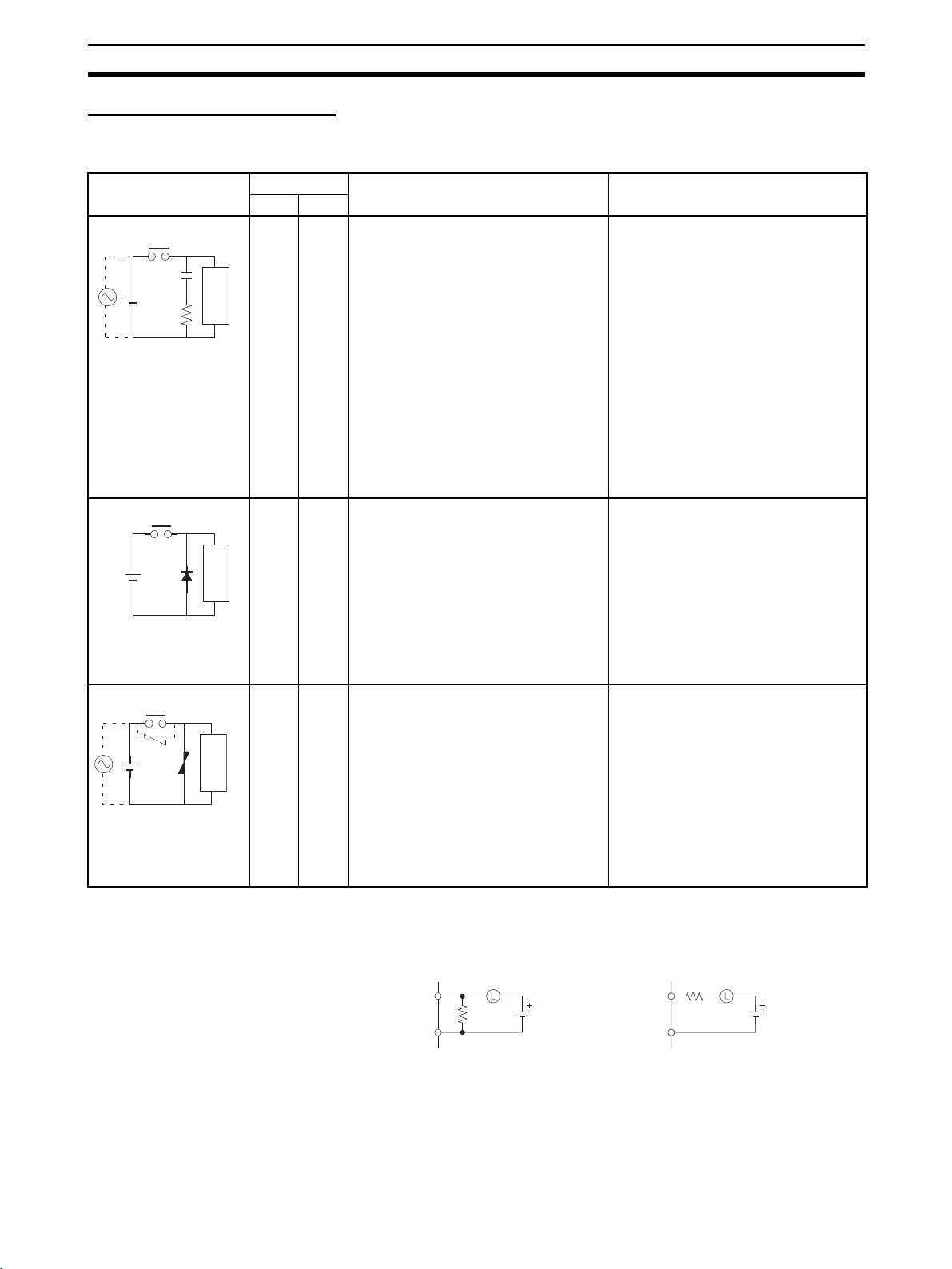
Countermeasure Examples
When switching an inductive load, connect an surge protector, diodes, etc., in
parallel with the load or contact as shown below.
Circuit Current Characteristic Required element
AC DC
CR method
Power
supply
Diode method
Power
supply
Varistor method
Power
supply
Yes Yes If the load is a relay or solenoid, there is
a time lag between the moment the circuit is opened and the moment the load
is reset.
If the supply voltage is 24 or 48 V, insert
Inductive
load
the surge protector in parallel with the
load. If the supply voltage is 100 to
200 V, insert the surge protector
between the contacts.
No Yes The diode connected in parallel with
the load changes energy accumulated
by the coil into a current, which then
flows into the coil so that the current will
be converted into Joule heat by the
Inductive
load
resistance of the inductive load.
This time lag, between the moment the
circuit is opened and the moment the
load is reset, caused by this method is
longer than that caused by the CR
method.
Yes Yes The varistor method prevents the impo-
sition of high voltage between the contacts by using the constant voltage
characteristic of the varistor. There is
time lag between the moment the cir-
Inductive
load
cuit is opened and the moment the load
is reset.
If the supply voltage is 24 or 48 V, insert
the varistor in parallel with the load. If
the supply voltage is 100 to 200 V,
insert the varistor between the contacts.
The capacitance of the capacitor must
be 1 to 0.5 µF per contact current of
1 A and resistance of the resistor must
be 0.5 to 1 Ω per contact voltage of 1 V.
These values, however, vary with the
load and the characteristics of the
relay. Decide these values from experiments, and take into consideration that
the capacitance suppresses spark discharge when the contacts are separated and the resistance limits the
current that flows into the load when
the circuit is closed again.
The dielectric strength of the capacitor
must be 200 to 300 V. If the circuit is an
AC circuit, use a capacitor with no
polarity.
The reversed dielectric strength value
of the diode must be at least 10 times
as large as the circuit voltage value.
The forward current of the diode must
be the same as or larger than the load
current.
The reversed dielectric strength value
of the diode may be two to three times
larger than the supply voltage if the
surge protector is applied to electronic
circuits with low circuit voltages.
---
When switching a load with a high inrush current such as an incandescent
lamp, suppress the inrush current as shown below.
Countermeasure 1 Countermeasure 2
OUT
R
COM
Providing a dark current of
pprox. one-third of the rated
alue through an incandescent
lamp
OUT
COM
Providing a limiting resisto
R
xxxi
Page 31

Conformance to EC Directives 6
xxxii
Page 32

SECTION 1
Overview
This section introduces the NSJ-series NSJ Controllers and describes differences between the NSJ Controllers and previous
OMRON products. Application precautions are also provided.
1-1 Overview. . . . . . . . . . . . . . . . . . . . . . . . . . . . . . . . . . . . . . . . . . . . . . . . . . . . . 2
1-1-1 The NSJ Series . . . . . . . . . . . . . . . . . . . . . . . . . . . . . . . . . . . . . . . . . 2
1-1-2 Features. . . . . . . . . . . . . . . . . . . . . . . . . . . . . . . . . . . . . . . . . . . . . . . 4
1-1-3 Types of NSJ Controllers . . . . . . . . . . . . . . . . . . . . . . . . . . . . . . . . . 5
1-1-4 Differences in Display Section System Versions . . . . . . . . . . . . . . . 6
1-1-5 System Configuration. . . . . . . . . . . . . . . . . . . . . . . . . . . . . . . . . . . . 8
1-1-6 Connecting a Programming Device . . . . . . . . . . . . . . . . . . . . . . . . . 11
1-2 Differences between the NSJ Controller and Previous Products . . . . . . . . . . 20
1-2-1 Differences between Controller Sections and CJ1G-CPU45H for
All Models of NSJ Controllers . . . . . . . . . . . . . . . . . . . . . . . . . . . . . 20
1-2-2 Differences between NSJ@-@@@@(B)-M3D Controller Sections
1-2-3 Differences between Display Section and NS-series PT . . . . . . . . . 21
1-2-4 Comparison of Ethernet Functionality for NSJ Controllers . . . . . . . 22
1-3 Internal Operation of NSJ Controllers . . . . . . . . . . . . . . . . . . . . . . . . . . . . . . 22
1-4 Application Precautions . . . . . . . . . . . . . . . . . . . . . . . . . . . . . . . . . . . . . . . . . 23
and CJ1G-CPU45H . . . . . . . . . . . . . . . . . . . . . . . . . . . . . . . . . . . . . 21
1
Page 33

Overview Section 1-1
1-1 Overview
1-1-1 The NSJ Series
NSJ-series NSJ Controllers are Programmable Controllers (PLCs) with user
interface display panels called Programmable Terminals (PTs) attached to
them. They combine the high-speed, high-capacity, multifunctional capabilities of a PLC with the interfacing capabilities of a PT.
The PLC portion of an NSJ Controller is called the Controller Section and
uses the same architecture as a CJ-series CJ1G-CPU45H CPU Unit with unit
version 3.0. DeviceNet master functionality is also built-in as a standard feature. Refer to the CJ Series Operation Manual (Cat. No. W393) for a description of the features. Refer to 1-2 Differences between the NSJ Controller and
Previous Products for a list of the differences between the Controller Section
of a NSJ Controller and a CJ1G-CPU45H CPU Unit with unit version 3.0.
The PT portion of an NSJ Controller is called the Display Section and uses
the same architecture as an NS-V2-series PT. Refer to 1-2 Differences
between the NSJ Controller and Previous Products for a list of the differences
between the Display Section of a NSJ Controller and an NS-V2-series PT.
Display Section
Same architecture as
an NS-series PT.
Controller Section
Same architecture as
a CJ-series CPU Unit.
RU
N
DeviceNet Master
Expansion Unit
I/O Control Unit (for connecting
Expansion Racks)
NSJ Controller Link Unit
NSJ Ethernet Unit
Note The Controller Section and Display Section form a one-piece unit and cannot
be separated from each other.
One of the following NSJ Expansion Units can be used with an NSJ Controller: NSJ Controller Link Unit, NSJ Ethernet Unit, or NSJ I/O Control Unit.
Using an NSJ I/O Control Unit enables connecting CJ-series Expansion
Racks.
2
Page 34

Overview Section 1-1
Basic NSJ Control
Configuration
An NSJ Controller consists of a Controller Section that is equivalent to a CJseries CJ1G-CPU45H CPU Unit with unit version 3.0 and a Display Section
that is equivalent to an NS-V2-series PT. The three NSJ Expansion Unit (NSJ
Controller Link Unit, NSJ Ethernet Unit, and NSJ I/O Control Unit) are equivalent to the CJ-series Units listed in the following table. Refer to 1-2 Differences
between the NSJ Controller and Previous Products for a list of the differences
between the Controller Section and Display Section of an NSJ Controller and
the original PLC and PT.
Name Model Configuration
Controller Section Display Section
Equivalent Unit Functional
NSJ Controller NSJ5-TQ@@(B)-G5D
NSJ5-SQ@@(B)-G5D
NSJ8-TV@@(B)-G5D NS8-TV@@(B)-V2
NSJ10-TV@@(B)-G5D NS10-TV@@(B)-V2
NSJ12-TS@@(B)-G5D NS12-TS@@(B)-V2
NSJ5-TQ@@(B)-M3D
(See note.)
NSJ5-SQ@@(B)-M3D
(See note.)
NSJ8-TV@@(B)-M3D
(See note.)
Built-in DeviceNet Section --- CJ1W-DRM21 --- --- --NSJ Controller Link Unit NSJW-CLK21-V1 CJ1W-CLK21-V1 Ver. 1.2 --- --NSJ Ethernet Unit NSJW-ETN21 CJ1W-ETN21 Ver. 1.4 --- --NSJ I/O Control Unit NSJW-IC101 CJ1W-IC101 --- --- ---
CJ1G-CPU45H
(See note.)
unit version
Ver. 3.0 NS5-TQ@@(B)-V2
Equivalent PT Functional
NS5-SQ@@(B)-V2
NS5-TQ@@(B)-V2
NS5-SQ@@(B)-V2
NS8-TV@@(B)-V2
version
Ver. 6.5 or
Ver. 6 . 6
Ver. 6 . 6
Note The NSJ@-@@@@(B)-M3D Controller Section differs from the CJ-series
CJ1G-CPU45H for the items listed in the following table.
Item CJ-series CJ1G-CPU45H
I/O capacity 1,280 points 640 points
Program capacity 60 Ksteps 20 Ksteps
Expansion Racks 3 max. 1 max.
EM Area 32 Kwords x 3 banks
E0_00000 to E2_32767
Function blocks Definitions 1,024 max. 128 max.
Instances 2,048 max. 256 max.
Flash memory FB program memory 1,024 Kbytes 256 Kbytes
Variable tables 128 Kbytes 64 Kbytes
None
@-@@@@(B)-M3D
NSJ
Controller Section
Programming Software Use CX-One version 1.1 or higher for NSJ@-@@@@(B)-G5D Controllers, and
use CX-One version 2.0 or higher for NSJ@-@@@@(B)-M3D Controllers.
Controller Section
Use CX-One version 1.1 or higher (CX-Programmer version 6.1 or higher and
CX-Integrator) for the Controller Section in an NSJ@-@@@@(B)-G5D Controller, and use CX-One version 2.0 or higher (CX-Programmer version 7.0 or
higher and CX-Integrator) for the Controller Section in an NSJ@-@@@@(B)-
M3D Controller.
Set the Device type in the CX-Programmer to NSJ. Use the following proce-
dure from the CX-Programmer.
3
Page 35

Overview Section 1-1
1,2,3... 1. Select File - New.
2. Select NSJ in the Change PLC Dialog Box.
Display Section
Use CX-One version 1.1 or higher (CX-Designer version 1.0 or higher) for the
Display Section in an NSJ@-@@@@(B)-G5D Controller, and use CX-One version 2.0 or higher (CX-Designer version 2.0 or higher) for the Display Section
in an NSJ@-@@@@(B)-M3D Controller.
Set the PT model in the CX-Designer to NSJ. Use the following procedure
from the CX-Designer.
1,2,3... 1. Select File - New Project.
2. Select NSJ for the Model in the New Project Dialog Box.
3. A host called “Controller” is used for the Controller Section in the NSJ Controller. When setting addresses in the Controller Section, set the host to
“Controller.”
1-1-2 Features
Complete Setup,
Programming, and
Monitoring Support with
the CX-One
Access All Functionality
through a Single Port
High-speed Controller
Section
32,768-color (Maximum)
Displays
Reduced Labor
Requirements
Reduced Space
Requirements
The CX-One Unified Development Environment provides all required functions, including those to program, debug, and operate the Controller Section,
create and transfer screens to the Display Section, and set up DeviceNet
communications. (Use CX-One version 2.0 or higher for the NSJ@-@@@@(B)-
M3D and CX-One version 1.1 or higher for all other NSJ Controllers.)
The CX-One (including CX-Programmer, CX-Integrator, and CX-Designer)
connects to either the USB port or one of the RS-232C ports (i.e., ports A and
B on the Display Section). All operations, such as programming the Controller
Section and transferring screens to the Display Section, can be achieved
through a single port. (Use CX-One version 2.0 or higher for the NSJ@-
@@@@(B)-M3D and CX-One version 1.1 or higher for all other NSJ Controllers.)
Instruction execution times (basic instructions from 0.04
instructions from 0.06
equivalent to those of a CJ1G-CPU45H CPU Unit with unit version 3.0.
The high-quality display capabilities of the Display Section are equivalent to
those of an NS-V2 PT.
When using a separate PLC and PT, the PLC and PT must be connected with
a cable and communications settings must be made in each. With the NSJ
Controllers, all of these connection and setting procedures are not required,
saving valuable installation and setup time.
NSJ Controllers can use DeviceNet for I/O to achieve a depth of only 73.3 mm
for the NSJ8/NSJ10/NSJ12 and only 79 mm for the NSJ5 (without an Expansion Unit). No additional space is required for the PLC to reduce space
requirements for installation.
µs) and other high-speed processing capabilities are
µs and special
I/O Control via DeviceNet The NSJ Controllers include master functionality for the DeviceNet open field
network. I/O can thus be controlled using a DeviceNet network within the
restrictions of the network communications cycle.
Mount an Expansion Unit One Expansion Unit can be connected to add CJ-series Expansion Racks, a
Controller Link port, or an Ethernet port.
4
Page 36

Overview Section 1-1
• Connect CJ-series Expansion Racks to use any required CJ-series Units.
An NSJ I/O Control Unit can be mounted to the back of the NSJ Controller
to connect up to three CJ-series Expansion Racks with a total of up to 30
CJ-series Units (10 Units per Rack). Any of the CJ-series Basic I/O Units,
Special I/O Units, and CPU Bus Units can be mounted to the CJ-series
Expansion Racks.
• If an NSJ I/O Control Unit is not mounted, either an NSJ Controller Link
Unit can be mounted to add a Controller Link port or an NSJ Ethernet Unit
can be mounted to add an Ethernet port. This enables either connecting
to a host via Ethernet or connecting to the pier-to-pier Controller Link network. Seamless communications are possible to integrate information
with the host or with other production lines.
Ladder Monitoring
Function (Display Section
System Version 6.6 or
Later, Except for NSJ5)
Special NSJ
Troubleshooting Features
Using the ladder monitoring function makes it possible to monitor the execution status of programs in the Controller Section or in other PLCs without having to use a Programming Device, such as a CX-Programmer or Programming
Console.
Special screens are provided on the Display Section that enable monitoring
the Controller Section or DeviceNet master functionality of the NSJ Controller.
Error information and countermeasures can be displayed. The alarm monitoring function of the Display Section can also be used to automatically switch to
the special screens when an alarm occurs.
Easy Backup of Controller
Section Using Display
Section Menus
The System Menu of the Display Section can be used to back up Controller
Section data onto a Memory Card.
1-1-3 Types of NSJ Controllers
There are two types of NSJ Controllers, as follows:
•NSJ@-@@@@(B)-G5D
•NSJ@-@@@@(B)-M3D
Differences between
Types of Controllers
The following points are different in the Controller Sections of NSJ@@@@@(B)-G5D and NSJ@-@@@@(B)-M3D Controllers. (The Display Sec-
tions are identical.)
I/O capacity 1,280 points 640 points
Program capacity 60 Ksteps 20 Ksteps
Data memory capacity 128 Kwords (DM
LD instruction processing speed 0.04 µs (Same as CJ1G-CPU45H)
Expansion Racks 3 max. 1 max.
Function
blocks
Built-in file
memory
Model
Definitions 1,024 max. 128 max.
Instances 2,048 max. 256 max.
FB program mem-
ory
Variable tables 128 Kbytes 64 Kbytes
@-@@@@(B)-
NSJ
G5D Controller
Section
Area: 32 Kwords, EM
Area: 32 Kwords x 3
banks)
1,024 Kbytes 256 Kbytes
NSJ@-@@@@(B)-
M3D Controller
Section
32 Kwords (DM Area:
32 Kwords, EM Area:
None)
5
Page 37

Overview Section 1-1
Selecting the Device
Type in the CXProgrammer Change
PLC Dialog Box
Using the CX-Programmer, either of the following can be selected as the
Device type in the Change PLC Dialog Box.
NSJ Controller type Selected device type Selected CPU type
NSJ
@-@@@@(B)-
G5D
@-@@@@(B)-
NSJ
M3D
NSJ G5D
M3D
1-1-4 Differences in Display Section System Versions
Item Previous versions New version
CX-Designer Version 1.0 (NS-CXDC1-V1) Version 2.0 (NS-CXDC1-V2)
System version of Display
Section
Integrated Simulation The only function available was simulated
Symbol programming without
addresses
Data security The following two types of data transfers
User security Any of five levels of passwords could be set
Consecutive line drawing Not available. Data in memory is treated as X and Y coor-
Version 6.5 Version 6.6
testing of Display Section screen operations on a personal computer.
Symbol names, addresses, and comments
were entered in symbol tables. Then the
required symbols were selected from the
symbol tables when creating screens.
are possible between CX-Designer (running on a personal computer) and the Display Section:
•Data transfers with the Display Section.
•With data transfers using a Memory Card,
data can be uploaded and downloaded by
any user.
for each functional object. A dialog box asking for the password was displayed each
time an attempt was made to use a functional object for which a password had
been set, and the object could not be used
unless the password was input.
Using a personal computer, a virtual Display Section can be connected to a virtual
Controller Section (CX-Simulator) to simulate NSJ Controller operation. This makes it
possible to reduce the total time involved in
debugging.
Symbol names and comments can be input
for symbol tables with no addresses. This
allows screens to be created using symbol
names without inputting addresses. Entering symbols in screen designs without
addresses makes it possible to reduce the
total time involved in design.
A password can now be set for creating
data. When data with a set password is
transferred to the Display Section, the
password is then required in order to
upload the data. This prevents users who
do not know the password from obtaining
that data from the Display Section. In addition, a password can be required to transfer
data to the Display Section. This prevents
data from being accidentally overwritten.
With the new version, once a user inputs
the password to use a functional object for
which a password has been set, a password does not have to be input again as
long as the user continues using only functional objects for which the same or lower
level passwords have been set. (Functional
objects with a higher-level passwords cannot be manipulated. A warning message
will be displayed if an attempt is made.)
This makes it possible to create applications that permit only the necessary operations by users who have entered a
password, and thus helps prevent faulty
operations.
dinates, and straight lines are drawn
between the applicable coordinates to create consecutive line drawing. This makes it
possible to handle applications involving
the drawing of various graphics in twodimensional space that could not be drawn
using the existing graph components.
6
Page 38

Overview Section 1-1
Item Previous versions New version
Improvements in broken-line
graph
Ladder Monitor Not supported. Built-in (except for NSJ5 Controllers)
Symbol table transfers when
transferring screen data
Holding log and alarm information when transferring screen
data
PLC data trace reading Not supported. (This was a function of the
Addition of European fonts With the built-in raster fonts in the Display
Japanese file names Two-byte characters could not be used for
SAP (Smart Active Parts) −−− SAP has been added for the EJ1 Modular
Automatically using symbol
names and I/O comments for
labels and alarm messages
Number of monitor points: 256 max. •Number of monitor points: 1,000 max.
•Batch reading
•Graph overwriting
•Indirect specification of starting display
position
•Indirect specification of displaying/hiding
graph lines
•Indirect specification of displaying/hiding
scale lines
Symbol tables set using the CX-Designer
could be managed only by the CXDesigner, and symbol data was lost when
data was uploaded from the NS-series Display Section.
All of the log and alarm information in the
Display Section was initialized when screen
data was downloaded.
CX-Programmer.)
Sections, Russian and Greek characters
were full-width and not all characters were
available.
project file names.
−−− The symbol names and I/O comments for
When screen data is downloaded from the
CX-Designer, the symbol tables are downloaded together with it. Likewise, when
screen data is uploaded, the symbol tables
are uploaded too.
It is now possible to select whether log and
alarm information is to be initialized when
screen data is downloaded.
Trace results from data traces (which is a
Controller Section function) can now be
read by the Display Section and displayed
in time chart format. (CSV files cannot be
saved.) This makes it possible to isolate the
causes of errors that occur on-site without
the CX-Programmer.
All Russian and Greek characters are now
available, and all characters are half-width.
Two-byte characters can now be used for
project file names.
Temperature Controller, G3ZA Multi-channel Power Controller, and Troubleshooters.
the set communications addresses can be
automatically used as the alarm messages
and label text strings for functional objects.
7
Page 39

Overview Section 1-1
r
1-1-5 System Configuration
Configuration with No
Expansion Unit
A Programming Device (e.g., CX-Programmer or CX-Designer) can be connected to the USB port or serial port A or B, which are on the Display Section.
The serial ports on the Display Section have the same functionality as the
ports on an NS-series PT. They can also be connected to a barcode reader,
temperature controller, or other external device when a Programming Device
is not connected.
Serial port C, which is on the Controller Section, has the same functionality as
the RS-232C port on a CJ1-H CPU Unit with unit version 3.0. It can be connected using Host Link, NT Link, no-protocol, or Serial Gateway (CompoWay/
F devices) protocols. Device master functionality is provided as a standard
feature, so I/O can be controlled using a DeviceNet network within the restrictions of the network communications cycle.
RUN
Support Software
Controller Section: CX-Programmer
Display Section: CX-Designer
DeviceNet
USB cable
or
or
RS-232C cable
Slaves
Barcode reader
Temperature controlle
Serial Gateway, etc.
8
Page 40

Overview Section 1-1
Mounting an Expansion
Unit
One Expansion Unit can be mounted to add CJ-series Expansion Racks, a
Controller Link port, or an Ethernet port.
Mounting an NSJ I/O Control Unit
For the NSJ@-@@@@(B)-M3D, an NSJ I/O Control Unit can be used to connect up to three CJ-series Expansion Racks with a total of up to 30 CJ-series
Units (10 Units per Rack). For all other NSJ Controllers, an NSJ I/O Control
Unit can be used to connect one CJ-series Expansion Rack with up to 10 CJseries Units.
Any of the CJ-series Basic I/O Units, Special I/O Units, and CPU Bus Units
can be mounted to an Expansion Rack.
I/O Control Unit
NSJW-IC101
CJ1W-II101 I/O Interface Unit
Power Supply
Unit
Up to 10 Units
CS1W-CN1@@@
I/O Connecting Cables
Power Supply
Units
CJ1W-II101 I/O Interface Unit
CJ1W-II101 I/O Interface Unit
CJ-series Basic I/O Units
CJ-series Special I/O Units
CJ-series CPU Bus Units
Up to 10 Units
Up to 10 Units
NSJ@-@@@@(B)-G5D
Up to 3 Racks
(3 x 10 Units max.)
NSJ@-@@@@(B)-M3D
Up to 1 Rack
(10 Units max.)
9
Page 41

Overview Section 1-1
Mounting an NSJ Controller Link Unit
Mounting an NSJ Controller Link Unit enables data links (program-free shared
data) between the NSJ Controller, other NSJ Controllers, and PLCs, as well
as as-needed message communications (FINS) between the NSJ Controller,
other NSJ Controllers, and PLCs. Data links and message communications
are also possible with computers connected to the Controller Link network.
NSJW-CLK21-V1
Controller Link Unit
R
U
N
R
U
N
Mounting an NSJ Ethernet Unit
Mounting an NSJ Ethernet Unit enables as-needed message communications
(FINS) between the NSJ Controller, host computers, other NSJ Controllers,
and PLCs connected to the Ethernet network. FTP commands can be sent
from host computers on the Ethernet network to read and write files in Memory Cards in the Controller Section of the NSJ Controller (see note). UDP or
TCP protocol can be used to send and receive any required data to provide
greater compatibility with higher-layer information networks.
NSJW-CLK21-V1
Controller Link Unit
CS/CJ-series PLC
Wired Controller Link Unit
NSJW-ETN21 Ethernet Unit
FINS communications
FTP server
Email communications
R
U
N
SMTP client
CS/CJ-series PLC
P
C
9
8
0
1
BX
N
E
C
Ethernet 100Base-TX
Note Only a Memory Card mounted in the Controller Section can be read with FTP
command when an NSJ Ethernet Unit is mounted. Files in the Memory Card
in the Display Section (e.g., screen data files) cannot be accessed.
10
Page 42

Overview Section 1-1
B
1-1-6 Connecting a Programming Device
Basic Connection
Connecting to the USB
Port
Connecting to an RS-232C
Port (Serial Port A or B)
Connect the Programming Device to the USB slave connector on the Display
Section using an off-the-shelf USB Cable. The connector on the Display Unit
is a type B USB connector.
RUN
USB
Off-the-shelf USB cable
USB port
CX-Programmer
Device type: NSJ
Network type: US
CX-Designer
Model: NSJ
Protocol: USB
Connect the Programming Device to serial port A or B using an XW2Z-200SCV/500S-CV RS-232C Cable.
R
U
N
RS-232C
P
C
-9
8
0
1
BX
N
E
C
CX-Programmer
Device type: NSJ
Network type: Toolbus
CX-Designer
Model: NSJ
Protocol: Serial
Connecting to the
Ethernet Port
XW2Z-200S-CV/500S-CV
RS-232C Cable
RS-232C port
(serial port A or B)
Connect the Programming Device to the Ethernet connector on an NSJ Controller with a built-in Ethernet port.
CX-Programmer
Device type: NSJ
Network type: Ethernet
Destination network address:
Ethernet network address of the NSJ Controller
Destination node address:
Ethernet node address of the NSJ Controller
CX-Designer
Model: NSJ
Protocol: Ethernet
Network address:
Ethernet network address of the NSJ Controller
Node address:
Ethernet node address of the NSJ Controller
Ethernet
R
U
N
Ethernet port
11
Page 43

Overview Section 1-1
System Configuration and Programming Device Connection
This section describes Programming Device connections in relation to the
type of system configuration in which the NSJ Controller is being used.
Only a built-in Ethernet port can be used to transfer screens to the Display
Section of an NSJ Controller using a network connection. Network transfers of
screen data are not possible through an NSJ Ethernet Unit or NSJ Controller
Link Unit.
NSJ Controllers without an Expansion Unit
Computer
Computer
USB or
Toolbus
connection
Connection to
Ethernet port on
Display Section
NSJ
Controller
DeviceNet
NSJ
Controller
DeviceNet
The Ethernet network address and node address must be set in the communications setting on the Comm Tab Page of the System Menu to enable using
the built-in Ethernet port of the NSJ Controller.
Programming Device
connection
USB Supported Supported Supported
Toolbus (serial port A or B) Supported Supported Supported
Built-in Ethernet port Supported Supported Supported
Operating the Controller Section
(setting I/O tables, transferring programs,
monitoring, etc.)
Setting up
DeviceNet
Transferring screens to
the Display Section
12
Note If communications become impossible between the Controller Section and
Display Section, CX-Programmer version 7.0 or later can be connected to
serial port C to read Controller Section data. Transferring screens to the Display Section and network operations, however, are not possible while connected to serial port C. Normally keep the CX-Programmer connected to the
USB or peripheral port (serial port A or B) or to the built-in Ethernet port.
Page 44

Overview Section 1-1
NSJ Controllers Connected via the Built-in Ethernet Port on the Display Section
Hub
Connection to built-in Ethernet port on Display Section
Computer
Ethernet
connection
Computer
USB or
Toolbus
connection
Hub
NSJ
Controller
DeviceNet
Connection to built-in Ethernet port on Display Section
NSJ
Controller
DeviceNet
NSJ
Controller
NSJ
Controller
NSJ
Controller
DeviceNet DeviceNet
NSJ
Controller
DeviceNet DeviceNet
The Ethernet network address and node address must be set in the communications setting on the Comm Tab Page of the System Menu to enable using
the built-in Ethernet port of the NSJ Controller. The NSJ Controllers must all
be set to the same network address.
Programming
Device
connection
Operating the
Controller Section
(setting I/O tables,
transferring
programs,
monitoring, etc.)
USB Supported Supported Supported Supported Supported Supported
Toolbus (serial
Supported Supported Supported Supported Supported Supported
port A or B)
Built-in Ether-
Supported Supported Supported Supported Supported Supported
net port
Local NSJ Controller
(directly connected to computer)
Setting up
DeviceNet
Transferring
screens to the
Display Section
Remote NSJ Controller
(connected via network)
Operating the
Controller Section
(setting I/O tables,
transferring
programs,
monitoring, etc.)
Setting up
DeviceNet
Transferring
screens to the
Display Section
13
Page 45

Overview Section 1-1
NSJ Controllers Connected via NSJ Ethernet Units or NSJ Controller Link Units
Computer
NSJ
Controller
NSJ
Controller
NSJ
Controller
USB connection,
Toolbus connection,
or connection to
built-in Ethernet port
on Display Section
Computer
USB connection,
Toolbus connection,
or connection to
built-in Ethernet port
on Display Section
NSJ
Controller
Controller Link
DeviceNet
Hub
DeviceNet
NSJ
Controller
DeviceNet DeviceNet
NSJ
Controller
Ethernet
DeviceNet DeviceNet
If Ethernet ports are used, the Ethernet network address and node address
must be set in the communications setting on the Comm Tab Page of the System Menu to enable using the built-in Ethernet port of the NSJ Controller. The
NSJ Controllers must all be set to the same network address. Routing tables
must also be set in all of the NSJ Controllers. Refer to Routing Table Setting
Example on page 16 for a setting example.
Programming
Device
connection
USB Supported Supported Supported Supported Supported Supported Not sup-
Toolbus (serial
port A or B)
Built-in Ethernet port
Setting
up
Controller
Link data
links
Operating the
Controller
Section (setting
I/O tables,
transferring
programs,
monitoring,
Local NSJ Controller
(directly connected to computer)
Setting up
DeviceNet
Transferring
screens to
the Display
Section
etc.)
Remote NSJ Controller
(connected via network)
Operating the
Controller
Section (setting
I/O tables,
transferring
programs,
monitoring,
etc.)
Setting up
DeviceNet
Transferring
screens to
the Display
Section
ported
Supported Supported Supported Supported Supported Supported Not sup-
ported
Supported Supported Supported Supported Supported Supported Not sup-
ported
14
Page 46

Overview Section 1-1
NSJ Controllers Connected via NSJ Ethernet Units or NSJ Controller Link Units and Connected to a
CS/CJ-series PLC
Computer
NSJ
Controller
NSJ
Controller
CS/CJ-series
PLC
Computer
USB connection,
Toolbus connection,
or connection to
built-in Ethernet port
on Display Section
Computer
USB connection,
Toolbus connection,
or connection to
built-in Ethernet port
on Display Section
A Programming Device connected to the USB port, a Toolbus port (serial port
A or B), or the built-in Ethernet port of the NSJ Controller can access and perform operations for a CS/CJ-series PLC on the same network.
A Programming Device connected to the peripheral port or Host Link port of
the NSJ Controller can perform operations, set up DeviceNet, and set up Controller Link data links for the Controller Sections of the NSJ Controllers, but it
cannot transfer screen data to the Display Sections of the NSJ Controllers.
To transfer screen data to the Display Section of an NSJ Controller, connect
the Programming Device to the USB port, a Toolbus port (serial port A or B),
or the built-in Ethernet port of the NSJ Controller.
Routing tables must also be set in all of the NSJ Controllers. Refer to Routing
Table Setting Example on page 16 for a setting example.
NSJ
Controller
Controller Link
DeviceNet
Hub
DeviceNet
NSJ
Controller
DeviceNet
Ethernet
DeviceNet
CS/CJ-series
PLC
Toolbus
connection
Computer
Toolbus
connection
Note When a CS/CJ-series PLC is operated via the network from Support Software
connected to the built-in Ethernet port of an NSJ Controller, the Frame Length
under the Network Settings in the Change PLC Type Dialog Box must be
changed from the default setting of 2000 to 1004 or less. Communications
cannot be executed normally if the frame length is set to 1005 or greater
because the maximum frame length of the inner bus in the NSJ Controller is
1004.
15
Page 47

Overview Section 1-1
Routing Table Setting
Example
Routing tables must also be set in all of the NSJ Controllers when using communications applications across a network or when setting an NSJ Controller
across a network. Routing tables are not required when using stand-along
NSJ Controllers or when not making NSJ Controller settings across a network.
The routing tables for the following configuration are described in this section
as an example. Routing tables are set using the CX-Integrator. Connect the
Programming Device to each NSJ Controller and transfer the routing table
created for each one.
Hub
Ethernet
connection
Computer
Network 1
NSJ
Controller 1
Node 1
NSJ
Controller 2
Node 2
Controller Link (network 2)
DeviceNet
(network 3)
DeviceNet
(network 4)
NSJ
Controller 3
Node 3
DeviceNet
(network 5)
16
The following unit numbers are used by the NSJ Controller.
Unit number of Built-in DeviceNet: 0
Unit number of NSJ Controller Link Unit
Page 48

Overview Section 1-1
■ Routing Tables for NSJ Controller 1
Local Network Table
Unit number Local network address
0 (built-in DeviceNet) 3
1 (NSJ Controller Link Unit) 2
228 (built-in Ethernet port) 1
Relay Network Table
Destination network
address
422
523
Network Address Setting for the Built-in Ethernet Port on the Display
Section of the NSJ Controller
The network address for the built-in Ethernet port is set using the communications settings on the Comm Tab Page on the System Menu of the Display
Section of the NSJ Controller. Set the network address to 1 (and set the IP
address and subnet mask). The address set here (1) is the same as the value
set in the local routing tables given above (228: built-in Ethernet port).
Relay network address Relay node address
Note Set the same network address for the built-in Ethernet on the System Menu of
the Display Section and in the routing tables of the Controller Section.
■ Routing Tables for NSJ Controller 2
Local Network Table
Unit number Local network address
0 (built-in DeviceNet) 4
1 (NSJ Controller Link Unit) 2
Relay Network Table
Destination network
address
121
321
523
■ Routing Tables for NSJ Controller 3
Relay network address Relay node address
Local Network Table
Unit number Local network address
0 (built-in DeviceNet) 5
1 (NSJ Controller Link Unit) 2
Relay Network Table
Destination network
address
121
321
422
Relay network address Relay node address
Note (1) When routing tables are transferred to the NSJ Controller from a Pro-
gramming Device, the built-in DeviceNet Section, Expansion Unit, and
Display Section of the NSJ Controller will be reset to enable using the
17
Page 49

Overview Section 1-1
new routing tables. Always confirm that resetting these parts of the NSJ
Controller will not adversely affect the system before transferring the routing tables.
(2) A communications error will occur when a Programming Device is con-
nected to the NSJ Controller and the Display Section is reset as a result
of transferring the routing tables. After the Display Section is restarted, it
may be necessary to connect/disconnect the Programming Device’s online connection.
Routing Table Precautions
■ Setting the Network Address for the Built-in Ethernet Port
To set the network address for the built-in Ethernet port on the NSJ Controller,
start the routing table setting tool from the CX Integrator and enter the network address for the built-in Ethernet port for port 1 of Unit 225 (Inner Board).
18
Click the Table V iew Tab, and the network address will be set for unit number
228. When setting the routing tables directly on the Table View Tab Page, set
the unit number to 228.
■ Using the NSJ Controller without Routing Tables
The NSJ Controller can be used without setting routing tables in the following
cases.
Page 50

Overview Section 1-1
Stand-alone NSJ Controllers
• Routing tables do not need to be set when the Programming Device is
connected to the USB port or Toolbus port (serial port A or B) on an NSJ
Controller.
• If the Programming Device is connected to the built-in Ethernet port on
the NSJ Controller, set the network address of the built-in Ethernet port
from the System Menu of the Display Section. Routing tables do not need
to be set.
Networked NSJ Controllers Not Using Communications Applications and
and for Which Settings Are Not Performed via the Network
To set up the NSJ Controllers, connect the Programming Device to the USB
port or Toolbus port (serial port A or B) on each NSJ Controller.
NSJ Controllers Networked with NSJ Ethernet Units or NSJ Controller
Link Units with a Programming Device Connected to the USB Port or
Toolbus Port (Serial Port A or B) on an NSJ Controller
Routing tables must be set in NSJ Controllers if more than one Communications Unit (including the built-in DeviceNet master of the NSJ Controller or
Communications Units on Expansion Racks connected via an NSJ I/O Control
Unit) is used. Routing tables do not need to be set, however, if the unit number of the built-in DeviceNet master is set to a smaller number than the unit
number of the NSJ Ethernet Unit or NSJ Controller Link Unit. Controller Link
data links can be set by setting the network address to 0 from the Programming Device.
19
Page 51

Differences between the NSJ Controller and Previous Products Section 1-2
1-2 Differences between the NSJ Controller and Previous
Products
This section describes the differences between the Controller Section of the
NSJ Controller and a CJ-series CJ1G-CPU45H CPU Unit and between the
Display Section of the NSJ Controller and an NS-series PT.
1-2-1 Differences between Controller Sections and CJ1G-CPU45H for
All Models of NSJ Controllers
Item CJ1G-CPU45H Controller Section
Power supply A Power Supply Unit is
required.
DeviceNet Unit A DeviceNet Unit must be
mounted separately as a CPU
Bus Unit.
CJ-series Basic I/O
Units, Special I/O
Units, and CPU Bus
Units
Peripheral port A peripheral port is provided. There is no peripheral port, but a USB port is provided instead. A
PLC Setup --- Operation Startup Condition Settings are provided.
Easy backup function
Auxiliary Area bit
allocations
Inner Board Area
allocations
Power interruption
detection delay
CJ-series Units can be
mounted.
The easy backup function is
controlled using DIP switch
settings.
--- The following bits have been added to the Auxiliary Area.
--- A Display Section Status Area has been added.
0 to 10 ms (Set by user;
default: 0 ms)
A Power Supply Unit is not required. (An external 24-V DC power
supply is connected to provide power to both the Display Section
and Controller Section.)
DeviceNet master functionality is built in. The functionality is equivalent to that of the CJ1W-DRM21.
• NSJ Expansion Units can be used instead of CJ-series Ethernet
or Controller Link Units (NSJW-ETN21 NSJ Ethernet Unit and
NSJW-CLK21-V1 NSJ Controller Link Unit).
• An NSJ I/O Control Unit (NSJW-IC101) can be mounted to
enable mounting CJ-series Basic I/O Units, Special I/O Units, and
CPU Bus Units to CJ-series Expansion Racks.
Programming Console cannot be connected.
Operation startup settings can be made after the Display Section
starts up.
DIP switch settings can be used, but the backup and comparison
features of the easy backup function can also be controlled from
the System Menu of the Display Section. Data cannot be restored
from the Display Section.
• A35500: Display Section Initializing Flag
• A39500: Fatal Error Flag
• A39501: Non-fatal Error Flag
• A40112: Display Section Fatal Error Flag
• A40108: Display Section Non-fatal Error Flag
• A42400 to A42403: Display Section Fatal Error Details
• A42404 to A42415: Display Section Non-fatal Error Details
• A60800: Display Section Restart Bit
• A34312: Verification Mismatch Flag
• CIO 1900: Display Section Mode Status
• CIO 1901: Display Section Screen Transfer Status
• CIO 1902: Display Section Error Status
Always 0 ms
20
Page 52

Differences between the NSJ Controller and Previous Products Section 1-2
1-2-2 Differences between NSJ@-@@@@(B)-M3D Controller Sections
and CJ1G-CPU45H
Item CJ-series CJ1G-CPU45H NSJ Controller Section
I/O capacity 1,280 points 640 points
Program capacity 60 Ksteps 20 Ksteps
Expansion Racks 3 max. 1 max.
EM Area 32 Kwords x 3 banks
E0_00000 to E2_32767
Function blocks Definitions 1,024 max. 128 max.
Instances 2,048 max. 256 max.
Flash memory FB program memory 1,024 Kbytes 256 Kbytes
Variable tables 128 Kbytes 64 Kbytes
None
1-2-3 Differences between Display Section and NS-series PT
Item NS-series PT Display Section
PLC/DeviceNet troubleshooting functions
Clock CPU Unit and PT cannot
Ladder monitor function
PT Programming Console
function
Device monitoring function Supported Supported
Built-in serial ports (serial
ports A and B)
Built-in Ethernet port The Controller Section can be accessed from a Programming
Display Section system
version 6.5
Display Section system
version 6.6
Display Section system
version 6.5
Display Section system
version 6.6
Not supported Supported (built-in)
• Controller Section and DeviceNet troubleshooting can be
selected from the System Memory of the Display Section.
• The alarm function of the Display Section can be registered
to display the Controller Section/DeviceNet Troubleshooting
Screen when an alarm occurs.
• Command buttons can be created to switch the screen to the
Controller Section /DeviceNet Troubleshooting Screen.
The Display Section is synchronized to the Controller Section.
be synchronized.
Supported (Copied to
Memory Card)
(See note 1.)
Built-in
(See notes 1 and 2.)
Supported (Copied to
Memory Card)
Supported (See note 3.) Supported (See note 4.)
The ports cannot be
used to access the CPU
Unit without setting routing tables.
The clock in the Controller Section can be set from the System Menu of the Display Section.
Not supported
Built-in (See note 1.)
Not supported
The Controller Section can be accessed from a Programming
Device (CX-Programmer or CX-Integrator).
Device (CX-Programmer or CX-Integrator).
(1) Ladder monitoring cannot be performed with the NS5 or NSJ5.
(2) With version-1 Controllers (-V1), copy the program to a Memory Card to
use ladder monitoring.
(3) The Programming Console function is built into the NS12/10/8-V2 Con-
trollers. With other Controllers, copy the program to a Memory Card to
use the Programming Console function.
(4) The Programming Console function cannot be used with a built-in Con-
troller Section. It can be used only through a NT Link (serial port A or B)
when connected to another PLC. Also the program must be copied to a
Memory Card to use the Programming Console function.
21
Page 53

Internal Operation of NSJ Controllers Section 1-3
1-2-4 Comparison of Ethernet Functionality for NSJ Controllers
Item Built-in Ethernet ports NSJ Ethernet Unit
Displaying and Setting Data
for Another Host (PLC)
Connection to a host computer Programming Device connections:
Sending and receiving Email Not supported Supported
Communications by executing
ladder program instructions
Data can be displayed and set for other
hosts on the Ethernet network. For example, it is possible to display and set at one
NSJ Controller the data of another NSJ
Controller or PLC.
Ethernet can be used for CX-One (CX-Programmer, CX-Designer, etc.). Screen data
and ladder programs can be transferred
from the host computer.
Accessing Display Section Memory Cards:
Ethernet can be used for accessing special
tools from the host computer or accessing
Display Section Memory Cards by FTP. For
example, Display Section recipe data,
alarms, and data log files can be acquired
from the host computer.
Accessing the host from host applications:
The Controller Section of an NSJ Controller
can be accessed from the host computer
using FINS communications. For example,
NSJ Controller DM can be read and written
from applications on the host computer.
(UDP only)
Not supported Socket service communications by execut-
The same functions are supported as
described to the left for the built-in Ethernet
port.
The same functions are supported as
described to the left for the built-in Ethernet
port (except that Display Section Memory
Cards cannot be accessed).
In addition, the following functions are supported:
Accessing Controller Section Memory
Cards
Clock-setting using SNTP function
TCP/IP compatibility
ing the CMND instruction
SEND and RECV instructions
Screen data can be transferred between NSJ Controllers using the CXDesigner across networks only if the NSJ Controllers are connected by the
built-in Ethernet ports on the NSJ controller.
1-3 Internal Operation of NSJ Controllers
The internal operation of the NSJ Controller is described in this section.
• The Controller Section and Display Section exchange data using the
Inner bus.
• The DeviceNet master function as well as the NSJ Controller Link Unit or
NSJ Ethernet Unit (Expansion Units) are handled as CJ-series CPU Bus
Units. CIO Area and DM Area words are allocated to these according the
unit numbers.
22
Page 54

Application Precautions Section 1-4
• CJ-series Expansion Racks can be connected by mounting an NSJ I/O
Control Unit. This enables mounting CJ-series Units.
Controller Section Display Section
Equivalent to
a CJ1G-CPU45H
CPU Unit with
unit version 3.0.
DeviceNet master function
Expansion Unit
· NSJ Controller Link Unit
· NSJ Ethernet Unit
· NSJ I/O Control Unit
NSJ Controller
Equivalent to
an NS-series PT
(See
with version 6.5
note.)
or 6.6.
Note: Inner bus used.
Handled as CJ-series
CPU Bus Units
CJ-series Expansion Rack
CJ-series Expansion Rack
CJ-series Expansion Rack
1-4 Application Precautions
• For the Programming Device, use CX-One version 2.0 or higher for the
NSJ@-@@@@(B)-M3D and use CX-One version 1.1 or higher for the NSJ
Controller. CX-One version 1.0 or lower does not support NSJ Controllers.
• NS-Designer version 6.2 or lower cannot be used to create screen data or
to transfer screen data to the Display Section of the NSJ Controller. Use
the CX-Designer bundled in CX-One version 1.1 or higher.
• The NSJ Controller does not have a peripheral port. Connect the Programming Device to the USB port or one of the serial ports (port A or B).
• More than one Support Software package (e.g., the CX-Programmer and
CX-Designer) can be connected to the NSJ Controller at the same time.
Online operations will be interrupted while screen data is being transferred using the CX-Designer, but will be enabled again once the transfer
has been completed.
• The Display Section will be reset after screen data has been transferred.
If other applications are connected online with the NSJ Controller, communications errors will occur until the Display Section has started up
again. With the USB port, the online connection will be automatically
restored. With a Toolbus connection (serial port A or B), the connection
will not be automatically restored and the connection must be made again
manually.
23
Page 55

Application Precautions Section 1-4
• Serial port C (on the Controller Section) has the same functionality as the
RS-232C port on a CJ1-H CPU Unit with unit version 3.0 except that a
Programming Device cannot be connected to serial port C. Connect the
Programming Device to the USB port or one of the serial ports (port A or
B).
• There is no peripheral port and a Programming Console thus cannot be
connected. Use the device monitoring function on the System Menu of the
Display Section for simple present value monitoring, present value setting, and similar operations.
• Set the same network address for the built-in Ethernet on the System
Menu of the Display Section and in the routing tables of the Controller
Section.
• When routing tables are transferred to the NSJ Controller from a Programming Device, the built-in DeviceNet Section, Expansion Unit, and
Display Section of the NSJ Controller will be reset to enable using the new
routing tables. Always confirm that resetting these parts of the NSJ Controller will not adversely affect the system before transferring the routing
tables.
• A communications error will occur when a Programming Device is connected to the NSJ Controller and the Display Section is reset as a result
of transferring the routing tables. After the Display Section is restarted, it
may be necessary to connect/disconnect the Programming Device's
online connection.
• An NS-AL002 RS-232C/RS-422A Conversion Unit cannot be connected
to serial port C. If the NS-AL002 is connected to serial port A on the
NSJ5-@@@@-@@@, it will not be physically possible to connect serial port
C. If the NS-AL002 is connected to serial port A or B on the NSJ8/10/12@@@@-@@@, serial port C cannot be used.
• Memory Cards are formatted before they are shipped. The user does not
have to format them before use. To reformat a Memory Card after use,
always use the CX-Programmer and format it in the Memory Card slot of
the Controller Section (MC (CONTROLLER) slot). The NSJ Controller
may not recognize a Memory Card that was formatted on a personal computer. A Memory Card formatted on a personal computer may not be
usable with the NSJ Controller even after reformatting the Memory Card
in the NSJ Controller.
• Applications started with the external application startup function of the
Display Section of the NSJ Controller cannot use the Programming Console function for the Controller Section. These can be used only for PLCs
connected to serial port A or B of the NSJ Controller.
• Always use RecoverUpdata_6_5 NSJ_HSH or a higher version (“6_5” is
shown as version V6.5) when using the recovery/update function for the
Display Section of the NSJ Controller. Data older than version 6.5 cannot
be used with the Display Section of the NSJ Controller.
• A DeviceNet multidrop connector cannot be connected to serial port B on
the NSJ5-@@@@-@@@. Do not use it. DeviceNet multidrop connectors
cannot be used with the NSJ8/10/12-@@@@-@@@.
24
Page 56

Application Precautions Section 1-4
• As shown in the following diagrams, corresponding terminals of the NSJ
Controller Link Unit are internally connected. If the communications connector is separated from a Unit, the communications line will be broken
and communications will be disabled. Use a Repeater Unit if it is necessary to add or delete nodes during operation.
CLK Unit
CLK Unit
CLK Unit
DB L
DB H
CLK Unit: Controller Link Unit
DB L
DB H
Repeater Unit
DB L
DB H
25
Page 57

Application Precautions Section 1-4
26
Page 58

Basic Operating Procedures
This section provides the basic operating procedures required to use the NSJ-series NSJ Controller.
2-1 Overall Operating Procedure. . . . . . . . . . . . . . . . . . . . . . . . . . . . . . . . . . . . . . 28
2-2 Installing the USB Driver . . . . . . . . . . . . . . . . . . . . . . . . . . . . . . . . . . . . . . . . 28
2-3 Operating Procedure for the Controller Section . . . . . . . . . . . . . . . . . . . . . . . 35
2-4 Operating Procedure for the Display Section . . . . . . . . . . . . . . . . . . . . . . . . . 36
SECTION 2
27
Page 59

Overall Operating Procedure Section 2-1
2-1 Overall Operating Procedure
The overall procedure required setup an NSJ Controller is given below.
1. Install and Wire the NSJ Controller
(including connecting a computer, see note).
2. Set the Switches.
· Set the DIP switches on the Controller Section and Display Section
· Set the rotary switch on the DeviceNet Section (i.e., the unit
number as a CPU Bus Unit and the DeviceNet node address).
Set the following if an NSJ Controller Link Unit or NSJ Ethernet
Unit is mounted: Unit number as a CPU Bus Unit and the
Controller Link or Ethernet node address.
3. Turn ON the Power Supply.
• Turn ON the NSJ Controller for the first time, select the language,
and set the time.
• If the DeviceNet Section is being used, turn ON the
communications power supply and the slave power supplies before
turning On power to the NSJ Controller.
2-2 Installing the USB Driver
2-3 Operating Procedure for Controller Section
2-4 Operating Procedure for Display Section
5. Start Operation.
(If the System Menu is displayed on the NSJ Controller, press
the Exit Button.)
6. Register and Start the NSJ Troubleshooter.
• Register the alarm function on the Display Section to
display the Troubleshooter Screen when an alarm occurs.
• Start the Troubleshooter from the System Menu.
SECTION 5 Installation
and Wiring and
Connecting Programming
Devices in 3-2 System
Configuration
4-1-2 Functions of Parts
3-2 Starting the PT in
Cat. No. V083
6-10 Starting Operations in
Cat. No. V083
10-2 NSJ Troubleshooter
Function
Note Here, the procedure is shown for connecting the computer and NSJ Controller
with a USB cable.
2-2 Installing the USB Driver
Install the USB driver in the personal computer. After installation, data can be
transferred between the personal computer and NSJ Controller via USB.
Applicable Operating
Systems
Operation Procedure Windows 2000 and Windows XP
1,2,3... 1. Start Windows 2000 or Windows XP.
28
Windows 98SE, Windows Me, Windows 2000, and Windows XP
2. Connect the personal computer to the USB slave connector using the USB
cable. The following Found New Hardware Wizard will be displayed.
Page 60

Installing the USB Driver Section 2-2
3. For Windows 2000, select Display a list of the known drivers for this device
so that I can choose a specific driver and click the Next Button. For Win-
dows XP, select Install from a list or specific location (Advanced) and click
the Next Button.
4. The dialog box shown below will be displayed. Confirm that Search for the
best driver for my device (Recommended) is selected. Select the Include this location in the search option, click the Browse Button and
specify the following CX-Server installation directory folder:
\USB
Then click the Next Button.
29
Page 61

Installing the USB Driver Section 2-2
5. The dialog box shown below will be displayed. Click the Continue Anyway
Button.
6. When installation is completed, the following dialog box will be displayed.
Click the Finish Button.
30
Page 62

Installing the USB Driver Section 2-2
Windows 98SE and Windows Me
1,2,3... 1. Start Windows 98SE or Windows Me.
2. Connect the personal computer to the USB slave connector using the USB
cable. The following Add New Hardware Wizard will be displayed. Click the
Next Button.
3. The following dialog box will be displayed. Select Search for the best driv-
er for your device (Recommended). Click the Next Button.
31
Page 63

Installing the USB Driver Section 2-2
4. Select Specify a location only and then click the Browse Button and
specify the following directory.
CX-Server installation directory
\USB
5. Click the Next Button.
32
6. Click the Next Button to start installation.
When installation is completed, the following dialog box will be displayed.
Click the Finish Button.
Page 64

Installing the USB Driver Section 2-2
7. The Add New Hardware Wizard will be displayed again. Click the Next Button.
8. The following dialog box will be displayed. Check that Search for the best
driver for your device (Recommended) is selected, and then click the
Next Button.
9. Select Specify a location only and then click the Browse Button and
specify the following directory.
CX-Server installation directory
\USB
33
Page 65

Installing the USB Driver Section 2-2
10. Click the Next Button.
11. Click the Next Button to start installation.
When installation is completed, the following dialog box will be displayed.
Click the Finish Button.
34
Page 66

Operating Procedure for the Controller Section Section 2-3
2-3 Operating Procedure for the Controller Section
1. Start the CX-Programmer.
Select Programs - OMRON - CX-One - CX-Programmer -
CX-Programmer (assuming that the CX-Programmer was installed in the
CX-Programmer group) or right-click the NSJ Controller in the Network
Configuration Window of the CX-Integrator and select Start Special
Application - Start Only from the pop-up menu.
2. Create a New Project.
Select File - New.
Input the following in the Change PLC Dialog Box.
• Device Name
• Select NSJ in the Device Type Field.
• Select USB in the Network Type Field.
3. Connect Online and Create I/O Tables.
Right-click the NSJ Controller in the I/O tables and select Start Special
Application - Start Only to start the CX-Designer. (See note.)
Set the following as required.
• Routing tables
• Built-in DeviceNet Section (Right-click DeviceNet in the I/O tables.)
• NSJ Controller Link (Right-click Controller Link in the I/O tables.)
CX-Programmer Operation Manual (Cat. No.
W446)
CX-Programmer Operation Manual (Cat. No.
W446)
CX-Programmer Operation Manual (Cat. No.
W446)
Section 3 Routing
Tables, Section 4 Data
Links for Controller
Link and SYSMAC
LINK, and Section 6
DeviceNet in CX-Integrator Operation Manual (Cat. No. W464)
2-4 Operating Procedure for Display Section
4. Set and Transfer the PLC Setup (as required).
5. Create, Transfer, and Monitor the Program.
6. Change the Operating Mode to MONITOR or RUN.
CX-Programmer Operation Manual (Cat. No.
W446)
CX-Programmer Operation Manual (Cat. No.
W446)
Note The CX-Designer can be started from the I/O tables in the CX-Programmer if
the CX-Programmer is installed as part of the CX-One.
35
Page 67

Operating Procedure for the Display Section Section 2-4
2-4 Operating Procedure for the Display Section
The following procedure outlines how to create screens and transfer them to
the Display Section using the CX-Designer. Refer to the following manuals for
details: CX-Designer Operation Manual (V088), CX-Designer Help, NS-series
PT Setup Manual (V083), and NS-series PT Programming Manual (V073).
1. Start the CX-Designer.
Select Programs - OMRON - CX-One - CX-Designer -
CX-Designer Ver. @.
2-3 Operating Procedure for Controller Section
2.
Create a New Project.
Select File - New Project.
Set the PT model to NSJ (system version 6.5 or higher)
and set the file name in the New Project Dialog Box.
Specify the screen number for the new screen in the New Screen Dialog Box.
3.
Make the Project Communications Settings and Register the Host.
Select Communication Setting on the project workspace System Tab
Page.
Alternatively, select PT - Communication Setting.
Set whether to use Serial Port A, Serial Port B, or Ethernet in the
Communication Setting Dialog Box and set the communications conditions.
Click the Add Host Button in the Communication
Setting Dialog Box and select the Controller as the host name.
If necessary, set the host name, host type, network address, and
node address.
Note: Up to 98 hosts can be registered in addition to ports A and B.
3-1 Starting and Exiting
CX-Designer in
Cat. No. V088
36
Copy symbols from the CX-Programmer Symbol
Table as required.
4.
Make Project System Settings.
Select System Setting on the project workspace System Tab Page.
Alternatively, select PT - System Setting.
The address allocation settings for system memory and the screen number to be
displayed at startup are set on the Initial Tab Page in the System Setting Dialog Box.
Set the project properties as required. Make settings such as language
selection and label settings when using the switch label function.
Select Project Properties on the project workspace System Tab Page.
Alternatively, select PT - Project properties.
Page 68

Operating Procedure for the Display Section Section 2-4
Note The settings made in the System Setting Dialog Box will overwrite the settings
made from the System Menu of the Display Section when screens are transferred.
Set the screen properties as required. Set the screen title, size,
pop-up screen setting, background and other settings.
Select PT - Screen/sheet properties.
7.
Create a New Screen.
Select File - New Screen.
8.
Create Functional Objects.
Select the functional object from the toolbar. Move the cursor to the screen
and drag the cursor from the start point to the end point of the functional object.
Select the functional object just placed on the screen and make address and
other settings from the property list. (Select the host name and set the address.
The address can also be set by selecting a symbol from the symbol table.)
Also set the properties for that functional object.
9.
Save the Screen. Select File - Save Screen/Sheet.
10.
Save the Project. Select File - Save All.
11.
Print data as required. Select File - Print.
12. Check operation using the screen data on the CX-Designer if required.
Select Tools - Test.
13. Transfer the screen data to the NSJ Controller.
Select the communications method.
Select PT - Transfer - Transfer Setting.
Transfer the screen data.
Select PT - Transfer - Transfer [Computer → PT].
14. Restart the Display Section Automatically.
(Automatically restarting the Display Section can be set when transferring
screen data.)
4-13 Integrated
Simulation for the
Entire System in
Cat. No. V088
37
Page 69

Operating Procedure for the Display Section Section 2-4
38
Page 70

SECTION 3
Specifications and System Configurations
This section provides the specifications of the NSJ-series NSJ Controller and describes the system configurations in which
it is used.
3-1 Specifications . . . . . . . . . . . . . . . . . . . . . . . . . . . . . . . . . . . . . . . . . . . . . . . . . 40
3-1-1 General Specifications . . . . . . . . . . . . . . . . . . . . . . . . . . . . . . . . . . . 40
3-1-2 Performance Specifications . . . . . . . . . . . . . . . . . . . . . . . . . . . . . . . 44
3-2 System Configuration . . . . . . . . . . . . . . . . . . . . . . . . . . . . . . . . . . . . . . . . . . . 62
3-2-1 Basic System Configuration . . . . . . . . . . . . . . . . . . . . . . . . . . . . . . . 62
3-2-2 Expanded System Configurations. . . . . . . . . . . . . . . . . . . . . . . . . . . 68
39
Page 71

Specifications Section 3-1
0
0
0
0
3-1 Specifications
3-1-1 General Specifications
NSJ Controller
Item Specifications
Model NSJ12-TS0@-G5D NSJ10-TV0@-G5D NSJ8-TV0@-G5D
NSJ8-TV0@-M3D
Supply voltage 24 V DC
Allowable supply voltage range 20.4 to 27.6 V DC (24 V DC ±15%)
Power consumption 30 W max. SQ0@: 21 W max.
Current consumption Controller Section, internal 5 V: 500 mA max.
DeviceNet Section, internal 5 V: 200 mA max.
DeviceNet Section, external 24 V: 18 mA max.
Inrush current (See note 1.) At 24 V DC: 10 A max. (for cold start) for 20 ms max.
Ambient operating temperature
(depending on angle of display
surface off horizontal)
60° to 90°: 0 to 50°C
30° to 60°: 0 to 45°C
0° to 30°: Use prohibited.
Ambient storage temperature −20 to 60°C
Ambient operating humidity 0° to 40°C: 35% to 85% (with no condensation)
40° to 50°C: 35% to 60% (with no condensation)
Ambient operating environment Must be no corrosive gases.
Insulation resistance 20 MΩ (at 100 V DC) between DC power supply terminals in power supply terminal
section and functional ground terminal
Dielectric strength 800 V DC for 1 minute between DC power supply terminals in power supply terminal
section and functional ground terminal with leakage current of 10 mA max.
Noise immunity 2 kV on power supply line (conforming to IEC61000-4-4)
Vibration resistance (during
operation)
Shock resistance (during operation)
External
dimensions
(See note 3.)
Without Expansion Unit
With Expansion
Unit
Panel cutout dimensions
10 to 57 Hz, 0.075-mm amplitude, 57 to 150 Hz, acceleration: 9.8 m/s
directions for 80 minutes
2
147 m/s
3 times each in X, Y, and Z directions
315 x 241 x 73.3 mm (W × H × D) 232 x 177 x 73.3
mm (W × H × D)
315 x 241 x 89.3 mm (W × H × D) 232 x 177 x 89.3
mm (W × H × D)
Width: 302 mm
Height: 228 mm
+1
0
+1
0
Panel thickness: 1.6 to 4.8 mm
Width: 220.5 mm
Height: 165.5
mm Panel thickness:
+0.5
0
+0.5
0
1.6 to 4.8 mm
Grounding Ground to 100 Ω or less.
Weight 2.7 kg max. 2.5 kg max. 2.0 kg max. 1.1 kg max.
Enclosure Front surface operating section: Equivalent to IP65 oil-proof type, NEMA4 (See note
4.)
Battery life 5 years (at 25°C) The SRAM and RTC will be backed up for 5 days after the battery
runs low (i.e., after the indicator lights orange). The SRAM and RTC will be backed
up by a super capacitor for 5 minutes after removing the old battery (i.e., after turning
ON power after 5 minutes).
International standards cULus and EC Directives
NSJ5-TQ0@-G5D
NSJ5-SQ0@-G5D
NSJ5-TQ0@-M3D
NSJ5-SQ0@-M3D
TQ0@: 22 W max.
30° to 90°: 0 to
50°C
0° to 30°: 0 to 40°C
2
in X, Y, and Z
195 x 142 x 79 mm
(W × H × D)
195 x 142 x 95 mm
(W × H × D)
Width: 184 mm
Height: 131 mm
+0.5
0
+0.5
0
Panel thickness:
1.6 to 4.8 mm
Note (1) A delay circuit that charges a capacitor is used to limit the inrush current.
If a hot start is performed when the power supply has been OFF only a
short period of time, the capacitor will still be charged and the inrush current specified above will be exceeded by up to approximately five times
40
Page 72

Specifications Section 3-1
the specified value. When selecting fuses or breakers for external circuits,
allow sufficient margin in shut-off performance.
(2) Display angles off horizontal are as follows:
90°
NSJ Controller Link
Unit
NSJ Ethernet Unit
NSJ I/O Control Unit
Display surface
30°
0° (horizontal)
(3) Refer to 4-2-1 Dimensions for details.
(4) May not be applicable in locations with long-term exposure to oil.
Item Specifications
Model NSJW-CLK21-V1
Current consumption 300 mA
Weight 100 g max.
Other specifications conform to those of the NSJ Controller.
Item Specifications
Model NSJW-ETN21
Current consumption 370 mA
Weight 100 g max.
Other specifications conform to those of the NSJ Controller.
Item Specifications
Model NSJW-IC101
Current consumption 20 mA
Weight 100 g max.
Other specifications conform to those of the NSJ Controller.
41
Page 73

Specifications Section 3-1
Power Supply Unit (when Connecting CJ-series Racks)
Item Specifications
Power Supply Unit CJ1W-PA205R CJ1W-PA205C CJ1W-PA202 CJ1W-PD025 CJ1W-PD022
Supply voltage 100 to 240 V AC (wide-range), 50/60 Hz 24 V DC
Operating voltage
and frequency
ranges
Power consumption
Inrush current
(See note 1.)
Output capacity 5.0 A, 5 V DC 2.8 A, 5 V DC 5.0 A, 5 V DC 2.0 A, 5 V DC
Output terminal
(service supply)
Replacement notification function
Insulation resistance
Dielectric strength
(See note 4.)
Noise immunity 2 kV on power supply line (conforming to IEC61000-4-4)
85 to 264 V AC, 47 to 63 Hz 19.2 to 28.8 V DC 21.6 to 26.4 V DC
100 VA max. 50 VA max. 50 W max. 35 W max.
At 100 to 120 V AC:
15 A/8 ms max. for cold start at room
temperature
At 200 to 240 V AC:
30 A/8 ms max. for cold start at room
temperature
0.8 A, 24 V DC 0.4 A, 24 V DC 0.8 A, 24 V DC 0.4 A, 24 V DC
Total: 25 W max. Total: 14 W max. Total: 25 W max. Total: 19.6 W max.
Not provided
Not provided. Provided.
Alarm output
(open-collector
output)
30 V DC max.,
50 mA max.
20 MΩ min. (at
500 V DC)
between AC external and GR terminals
(See note 3.)
2,300 V AC
50/60 Hz for 1 min
between AC external and GR terminals (See note 3.)
Leakage current:
10 mA max.
1,000 V AC 50/60 Hz for 1 min between DC external and GR terminals (See note
3.), Leakage current: 10 mA max.
20 MΩ min. (at
500 V DC)
between all external terminals and
GR terminal, and
between all alarm
output terminals.
20 MΩ min. (at
250 V DC)
between all alarm
output terminals
and GR terminal.
2,300 V AC,
50/60 Hz for 1
minute between
AC external terminals and GR terminal with a
leakage current of
10 mA max.
1,000 V AC,
50/60 Hz for 1
minute between all
alarm output terminals with a leakage current of
10 mA max.
At 100 to 120 V AC:
20 A/8 ms max. for
cold start at room
temperature
At 200 to 240 V AC:
40 A/8 ms max. for
cold start at room
temperature
Not provided.
20 MΩ min. (at
500 V DC)
between AC external and GR terminals
(See note 3.)
2,300 V AC
50/60 Hz for 1 min
between AC external terminals and
GR terminal with a
leakage current of
10 mA max. (See
note 3.)
At 24 V DC:
30 A/20 ms max. for cold start at room
temperature
20 MΩ min. (at
500 V DC)
between DC external and GR terminals (See note 3.)
1,000 V AC
50/60 Hz for 1
min between DC
external terminals
and GR terminal
with a leakage
current of 10 mA
max. (See note 3.)
--- (See note 6.)
--- (See note 6.)
42
Page 74

Specifications Section 3-1
Item Specifications
Vibration resistance
Shock resistance
Ambient operating
temperature
Ambient operating
humidity
Atmosphere Must be free from corrosive gases.
Ambient storage
temperature
Grounding Ground to less than 100 Ω
Enclosure Mounted in a panel.
Weight All Racks are each 5 kg max.
Safety measures Conforms to cULus and EC Directives.
10 to 57 Hz, 0.075-mm amplitude, 57 to 150 Hz, acceleration: 9.8 m/s
80 minutes (Time coefficient: 8 minutes × coefficient factor 10 = total time 80 min.)
2
147 m/s
0 to 55°C
10% to 90% (with
no condensation)
–20 to 75°C
(excluding battery)
3 times each in X, Y, and Z directions (Relay Output Unit: 100 m/s2)
10% to 90% (with
no condensation)
(See note 5.)
–20 to 75°C (See
note 5.)
Note 1. The inrush current is given for a cold start at room temperature for AC Pow-
er Supply Units and for a cold start for DC Power Supply Units. The inrush
control circuit uses a thermistor element with a low-temperature current
control characteristic. If the ambient temperature is high or the NSJ Controller is hot-started, the thermistor will not be sufficiently cool, and the inrush currents given in the table may be exceeded by up to twice the given
values. When selecting fuses or breakers for external circuits, allow sufficient margin in shut-off performance.
A delay circuit that charges a capacitor is used to limit the inrush current in
DC Power Supply Units. If a hot start is performed when the power supply
has been OFF only a short period of time, the capacitor will still be charged
and the inrush current specified above will be exceeded by up to approximately twice the specified value.
2. Disconnect the Power Supply Unit’s LG terminal from the GR terminal
when testing insulation and dielectric strength. Testing the insulation and
dielectric strength with the LG terminal and the GR terminals connected
will damage internal circuits in the NSJ Controller.
3. Change the applied voltage gradually using the adjuster on the Tester. If
the full dielectric strength voltage is applied or turned OFF using the switch
on the Tester, the generated impulse voltage may damage the Power Supply Unit.
4. Maintain an ambient storage temperature of
humidity of 25% to 70% when storing the Unit for longer than 3 months to
keep the replacement notification function in optimum working condition.
5. CJ1W-PD022 is not insulated between the primary DC power and secondary DC power.
10% to 90% (with no condensation)
–20 to 75°C (excluding battery)
2
in X, Y, and Z directions for
−25 to 30°C and an ambient
43
Page 75

Specifications Section 3-1
3-1-2 Performance Specifications
Controller Section
Model I/O bits User
NSJ5-TQ00-G5D
NSJ5-TQ00B-G5D
NSJ5-TQ01-G5D
NSJ5-TQ01B-G5D
NSJ5-SQ00-G5D
NSJ5-SQ00B-G5D
NSJ5-SQ01-G5D
NSJ5-SQ01B-G5D
NSJ8-TV00-G5D
NSJ8-TV00B-G5D
NSJ8-TV01-G5D
NSJ8-TV01B-G5D
NSJ10-TV00-G5D
NSJ10-TV00B-G5D
NSJ10-TV01-G5D
NSJ10-TV01B-G5D
NSJ12-TS00-G5D
NSJ12-TS00B-G5D
NSJ12-TS01-G5D
NSJ12-TS01B-G5D
NSJ5-TQ00-M3D
NSJ5-TQ00B-M3D
NSJ5-TQ01-M3D
NSJ5-TQ01B-M3D
NSJ5-SQ00-M3D
NSJ5-SQ00B-M3D
NSJ5-SQ01-M3D
NSJ5-SQ01B-M3D
NSJ8-TV00-M3D
NSJ8-TV00B-M3D
NSJ8-TV01-M3D
NSJ8-TV01B-M3D
1,280 60
640 20
pro-
gram
mem-
ory
(See
note.)
Ksteps
Ksteps
Data
Mem-
ory
32
Kwords
Extend
ed Data
Mem-
ory
32
Kwords
x 3
banks
E0_000
00 to
E2_327
67
None 128 256 256
Function blocks Flash memory
Max.
No. of
defini-
tions
1,024 2,048 1,024
Max.
No. of
in-
stances
FB pro-
gram
mem-
Kbytes
Kbytes
ory
Com-
ment
file
64
Kbytes
Pro-
gram
index
file
64
Kbytes
Sym-
bol
table
128
Kbytes
64
Kbytes
44
Note The number of steps in a program is not the same as the number of instruc-
tions. Each instruction requires from 1 to 7 steps. For example, LD and OUT
require 1 step each, but MOV(021) requires 3 steps. The program capacity
indicates the total number of steps for all instructions in the program. Refer to
10-4 Instruction Execution Times and Number of Steps in the CJ Series Setup
Manual for the number of steps required for each instruction.
Page 76

Specifications Section 3-1
Display Section
Model Display panel (See note 5.) Backlight (See note 1.)
Display
device
NSJ5-TQ00-G5D High-defiNSJ5-TQ00B-G5D
NSJ5-TQ01-G5D
NSJ5-TQ01B-G5D
NSJ5-TQ00-M3D
NSJ5-TQ00B-M3D
NSJ5-TQ01-M3D
NSJ5-TQ01B-M3D
NSJ5-SQ00-G5D Color STN
NSJ5-SQ00B-G5D
NSJ5-SQ01-G5D
NSJ5-SQ01B-G5D
NSJ5-SQ00-M3D
NSJ5-SQ00B-M3D
NSJ5-SQ01-M3D
NSJ5-SQ01B-M3D
NSJ8-TV00-G5D High-defiNSJ8-TV00B-G5D
NSJ8-TV01-G5D
NSJ8-TV01B-G5D
NSJ8-TV00-M3D
NSJ8-TV00B-M3D
NSJ8-TV01-M3D
NSJ8-TV01B-M3D
NSJ10-TV00-G5D 215.2 ×
NSJ10-TV00B-G5D
NSJ10-TV01-G5D
NSJ10-TV01B-G5D
NSJ12-TS00-G5D 246.0 ×
NSJ12-TS00B-G5D
NSJ12-TS01-G5D
NSJ12-TS01B-G5D
nition TFT
color LCD
LCD
nition TFT
color LCD
Effective
area
117.2 ×
88.4 mm
(W × H)
(5.7
inches)
115.2 ×
86.4 mm
(W × H)
(5.7
inches)
170.9 ×
128.2 mm
(W × H)
(8.4
inches)
162.4 mm
(W × H)
(10.4
inches)
184.5 mm
(W × H)
(12.1
inches)
Number
of dots
320 × 240
(QVGA)
640 × 480
(VGA)
800 × 600
(QVGA)
Display
color
256 colors
(32,768
colors for
BMP/JPE
G images)
256 colors
(4,096 colors for
BMP/JPE
G images)
256 colors
(32,768
colors for
BMP/JPE
G images)
View
angle
Left/right
±70°, Top
70°, Bottom 50°
Left/right
±50°, Top
45°, Bottom 50°
Left/right
±65°, Top
50°, Bottom 60°
Left/right
±60°, Top
35°, Bottom 65°
Left/right
±60°, Top
45°, Bottom 75°
Life
expect-
ancy (See
note 2.)
75,000
hours min.
75,000
hours min.
50,000
hours min.
50,000
hours min.
50,000
hours min.
Bright-
ness
adjust-
ment (See
note 3.)
There are
3 levels of
adjustment by
operating
the touch
panel.
Backlight
error
detection
(See note
4.)
Error is
detected
automatically, and
the RUN
indicator
flashes
green for
notification.
Note (1) Contact your nearest OMRON representative to replace the backlight.
(2) This is the estimated time before brightness is reduced by half at room
temperature and humidity. It is not a guaranteed value. The life expectancy will be drastically shortened if the NSJ Controller is used at low temperatures. For example, use at temperatures of 0°C will reduce the life
expectancy to approximately 10,000 hours (reference value).
(3) The brightness cannot be adjusted much.
(4) This function does not detect service life expectancy. It detects when the
backlight is not lit due to a disconnection or other errors. Backlight error
detection indicates that all backlights (2) are OFF.
45
Page 77

Specifications Section 3-1
(5) There are sometimes faulty pixels in the touch panel of the Display Sec-
tion, but this does not indicate an error as long as the number of bright or
dark pixels does not exceed the following limits.
Model Limit
NSJ12-TS0@(B)-@@@
NSJ10-TV0@(B)-@@@
NSJ8-TV0@(B)-@@@
NSJ5-@Q0@(B)-@@@ 4 total defects max. of the following size with no more
10 bright or dark pixels max. with no more than 3
contiguous defective pixels.
than one per 20-mm square:
0.2 mm < (short dia. + long dia.)/2 ≤ 0.55 mm
46
Page 78

Specifications Section 3-1
Other Display Section Specifications
Model Touch panel (matrix type) Stan-
Method Number of
NSJ5-TQ00-M3D Resistive
NSJ5-TQ00-G5D
NSJ5-TQ00B-M3D Black
NSJ5-TQ00B-G5D
NSJ5-TQ01-M3D 10/100
NSJ5-TQ01-G5D
NSJ5-TQ01B-M3D Black
NSJ5-TQ01B-G5D
NSJ5-SQ00-M3D None Ivory
NSJ5-SQ00-G5D
NSJ5-SQ00B-M3D Black
NSJ5-SQ00B-G5D
NSJ5-SQ01-M3D 10/100
NSJ5-SQ01-G5D
NSJ5-SQ01B-M3D Black
NSJ5-SQ01B-G5D
NSJ8-TV00-M3D 768 (32
NSJ8-TV00-G5D
NSJ8-TV00B-M3D Black
NSJ8-TV00B-G5D
NSJ8-TV01-M3D 10/100
NSJ8-TV01-G5D
NSJ8-TV01B-M3D Black
NSJ8-TV01B-G5D
NSJ10-TV00-G5D 1,200 (40
NSJ10-TV00B-G5D Black
NSJ10-TV01-G5D 10/100
NSJ10-TV01B-G5D Black
NSJ12-TS00-G5D 1,900 (50
NSJ12-TS00B-G5D Black
NSJ12-TS01-G5D 10/100
NSJ12-TS01B-G5D Black
membrane
switches
300 (20
horizontal
15 vertical)
× 16
16
dots for
each switch
horizontal
24 vertical)
20
× 20
dots for
each switch
horizontal
30 vertical)
× 16
16
dots for
each switch
horizontal
58 vertical)
× 16
16
dots for
each switch
Input Service
Pressure-
×
sensitive
×
×
×
life
1,000,000
touch
operations.
dard
screen
data
capacity
20 MB 1 port 3 ports
60 MB None 1 port Ivory
Built-in
USB
slave
port
Built-in
RS-232C
port
(Display
Section:
A and B,
Controller Section: C
Built-in
Ether-
None None Japa-
Base-T
Base-T
Base-T
None Ivory
Base-T
None Ivory
Base-T
net
Built-in
USB
printer
port
Lan-
guage
nese
and
English
Frame
color
Ivory
Ivory
Ivory
Ivory
Ivory
Ivory
Built-in Serial Ports
Built-in Ethernet Port
Port Description
USB slave port (for
Programming Device
Can be connected to a computer running the CX-Programmer
or CX-Designer. Set the network type to “USB.”
connection)
Serial port C (on
Controller Section)
Serial ports A and B
(on Display Section)
Serial communications modes: Toolbus, Host Link, Non-protocol, NT Link, or Serial Gateway
Serial communications modes: Toolbus, Host Link, Non-protocol (barcode reader only), NT Link, or CompoWay/F (Temperature Controller.)
Port Description
Built-in Ethernet port • FINS message communications (send and receive)
• FTP server (Accesses Memory Card in Display Section.)
47
Page 79

Specifications Section 3-1
Common Specifications
Controller Section
Item Specifications Reference
Control method Stored program ---
I/O control method Cyclic scan and immediate processing are both possible. ---
Programming Ladder diagram ---
CPU processing mode Normal Mode, Parallel Processing Mode with Asynchronous Memory
Access, Parallel Processing Mode with Synchronous Memory Access,
or Peripheral Servicing Priority Mode
Instruction length 1 to 7 steps per instruction CJ Series Operation
Ladder instructions Approx. 400 (3-digit function codes) ---
Execution time Basic instructions: 0.04 µs min.
Special instructions: 0.06 µs min.
Overhead time
Mounting method Mounted using Panel Mounting Bracket. This manual: 5-1-3
Mountable Expansion
Units
Number of Expansion
Racks
Connectable Units Per Expansion Rack: 10 Units including Basic I/O Units, Special I/O
Number of tasks 288 (cyclic tasks: 32, interrupt tasks: 256)
Normal mode: 0.3 ms min.
Parallel processing: 0.3 ms min.
One of the following Units can be mounted.
NSJ I/O Control Unit (NSJW-IC101)
NSJ Controller Link Unit (NSJW-CLK21-V1)
NSJ Ethernet Unit (NSJW-ETN21)
One CJ-series Expansion Rack can be connected to the NSJ@-
@@@@-M3D and up to three CJ-series Expansion Racks can be connected to all other NSJ Controllers by mounting an NSJ I/O Control
Unit (NSJW-IC101).
Each Expansion Rack requires an CJ-series I/O Interface Unit (CJ1WII101) and a Power Supply Unit.
Units, and CPU Bus Units.
NSJ@-@@@@-G5D: Total per NSJ Controller: 10 Units on each of 3
Expansion Racks = 30 Units total
NSJ@-@@@@-M3D: Total per NSJ Controller: 10 Units on one Expansion Rack = 10 Units total
Interrupt tasks can be defined as cyclic tasks called “extra cyclic
tasks.” Including these, up to 288 cyclic tasks can be used.
Note 1 Cyclic tasks are executed each cycle and are controlled with
TKON(820) and TKOF(821) instructions.
Note 2 The following 3 types of interrupt tasks are supported.
Power OFF interrupt tasks: 1 max.
Scheduled interrupt tasks: 2 max.
External interrupt tasks: 256 max.
---
Manual (W393): 10-5
Instruction Execution
Times and Number of
Steps
CJ Series Operation
Manual (W393): 10-5
Instruction Execution
Times and Number of
Steps
---
Mounting the NSJ Controller to the Control
Panel
This manual: 3-2 System Configuration
CJ Series Operation
Manual (W393): 2-3-3
CJ-series Expansion
Racks
CJ Series Operation
Manual (W393): 2-3-3
CJ-series Expansion
Racks
CS/CJ Series Programming Manual (W394):
1-3 Programs and
Ta s k s and
SECTION 4: Tasks
48
Page 80

Specifications Section 3-1
Item Specifications Reference
Interrupt types Scheduled Interrupts:
Calling subroutines
from more than one
task
Function blocks Languages in function block definitions: ladder programming, struc-
CIO
I/O Area 2,560 (160 words): CIO 000000 to CIO 015915 (80 words
(Core
I/O)
Area
Link Area 3,200 (200 words): CIO 10000 to CIO 119915 (words CIO
CPU Bus Unit
Area
Inner Board
Area
Special I/O Unit
Area
Interrupts generated at a time scheduled by the Controller Section’s
built-in timer. (See note. 1)
Power OFF Interrupts (See note 2.):
Interrupts executed when the Controller Section’s power is turned
OFF.
External I/O Interrupts:
Interrupts from the Special I/O Units or CPU Bus Units.
Note 1 Scheduled interrupt time interval is either 1 ms to 9,999 ms
Note 2 Not supported when the CJ1W-PD022 Power Supply Unit is
Supported (called “global subroutines”). CS/CJ Series Program-
tured text
from CIO 0000 to CIO 0159)
The setting of the first word can be changed from the
default (CIO 0000) so that CIO 0000 to CIO 0999 can be
used.
I/O bits are allocated to Basic I/O Units.
1000 to CIO 1199)
6,400 (400 words): CIO 150000 to CIO 189915 (words CIO
1500 to CIO 1899)
CPU Bus Unit bits store the operating status of CPU Bus
Units (25 words per Unit, 16 Units max.).
1,600 (100 words): CIO 190000 to CIO 199915 (words CIO
1900 to CIO 1999)
Inner Board bits are allocated to storing Display Section
Status
15,360 (960 words): CIO 200000 to CIO 295915 (words
CIO 2000 to CIO 2959)
Special I/O Unit bits are allocated to Special I/O Units (10
words per Unit, 96 Units max.).
or 10 ms to 99,990 ms, in units of 1 ms or 10 ms.
mounted.
The CIO
Area can
be used
as work
bits if the
bits are
not used
as shown
here.
CS/CJ Series Programming Manual (W394):
4-3 Interrupt Tasks
ming Manual (W394):
4-2-5 Global Subroutines
CX-Programmer Ver.
6.@ CS1-H, CJ1-H,
CJ1M CPU Units Operation Manual Function
Blocks (W438)
CJ Series Operation
Manual (W393):9-3 I/O
Area
CJ Series Operation
Manual (W393):9-4
Data Link Area and 2-53 Communications Network System
Controller Link Unit
Operation Manual
(W309)
CJ Series Operation
Manual (W393):9-5
CPU Bus Unit Area
Operation Manual for
each CPU Bus Unit
---
CJ Series Operation
Manual (W393):9-6
Special I/O Unit Area
Operation Manual for
each Special I/O Unit
49
Page 81

Specifications Section 3-1
Item Specifications Reference
CIO
DeviceNet Area 9,600 (600 words): CIO 320000 to CIO 379915 (words CIO
(Core
I/O)
Area
3200 to CIO 3799)
DeviceNet bits are allocated to Slaves for DeviceNet Sec-
tion remote I/O communications when the master is used
with fixed allocations.
Fixed allocation
setting 1
Fixed allocation
setting 2
Fixed allocation
setting 3
The following words are allocated in the master when the
DeviceNet Section is used as a slave with fixed allocations.
Outputs: CIO 3200 to CIO 3263
Inputs: CIO 3300 to CIO 3363
Outputs: CIO 3400 to CIO 3463
Inputs: CIO 3500 to CIO 3563
Outputs: CIO 3600 to CIO 3663
Inputs: CIO 3700 to CIO 3763
The CIO
Area can
be used
as work
bits if the
bits are
not used
as shown
here.
DeviceNet Unit Operation Manual (W380)
CJ Series Operation
Manual (W393): 9-7
DeviceNet Area
Fixed allocation
setting 1
Fixed allocation
setting 2
Fixed allocation
setting 3
Internal I/O
Area
Wor k Area 8,192 bits (512 words): W00000 to W51115 (W000 to W511)
Holding Area 8,192 bits (512 words): H00000 to H51115 (H000 to H511)
Auxiliary Area Read-only: 7,168 bits (448 words): A00000 to A44715 (words A000 to
Temporary Area 16 bits (TR0 to TR15)
Timer Area 4,096: T0000 to T4095 (used for timers only) CJ Series Operation
4,800 (300 words): CIO 120000 to CIO 149915 (words CIO 1200 to
CIO 1499)
37,504 (2,344 words): CIO 380000 to CIO 614315 (words CIO 3800 to
CIO 6143)
These bits in the CIO Area are used as work bits in programming to
control program execution. They cannot be used for external I/O.
Controls the programs only. (I/O from external I/O terminals is not possible.)
Note When using work bits in programming, use the bits in the Work
Area first before using bits from other areas.
Holding bits are used to control the execution of the program, and
maintain their ON/OFF status when the NSJ Controller is turned OFF
or the operating mode is changed.
Note The Function Block Holding Area words are allocated from
H512 to H1535. These words can be used only for the function
block instance area (internally allocated variable area).
A447)
Read/write: 8,192 bits (512 words): A44800 to A95915 (words A448 to
A959)
Auxiliary bits are allocated specific functions.
Temporary bits are used to temporarily store the ON/OFF execution
conditions at program branches.
Outputs: CIO 3370 (Master to Slave)
Inputs: CIO 3270 (Slave to Master)
Outputs: CIO 3570 (Master to Slave)
Inputs: CIO 3470 (Slave to Master)
Outputs: CIO 3770 (Master to Slave)
Inputs: CIO 3670 (Slave to Master)
CJ Series Operation
Manual (W393): 9-2-2
Overview of the Data
Areas
CJ Series Operation
Manual (W393): 9-2-2
Overview of the Data
Areas and 9-7 Serial
PLC Link Area
CJ Series Operation
Manual (W393): 9-2-2
Overview of the Data
Areas and 9-10 Holding
Area
CJ Series Operation
Manual (W393): 9-2-2
Overview of the Data
Areas and 9-11
Auxiliary Area
CJ Series Operation
Manual (W393): 9-2-2
Overview of the Data
Areas and 9-12 TR
(Temporary Relay) Area
Manual (W393): 9-2-2
Overview of the Data
Areas and 9-13 Timer
Area
50
Page 82

Specifications Section 3-1
Item Specifications Reference
Counter Area 4,096: C0000 to C4095 (used for counters only) CJ Series Operation
DM Area 32 Kwords: D00000 to D32767
Used as a general-purpose data area for reading and writing data in
word units (16 bits). Words in the DM Area maintain their status when
the NSJ Controller is turned OFF or the operating mode is changed.
Internal Special I/O Unit DM Area: D20000 to D29599 (100 words ×
96 Units)
Used to set parameters for Special I/O Units.
CPU Bus Unit DM Area: D30000 to D31599 (100 words × 16 Units)
Used to set parameters for CPU Bus Units.
EM Area NSJ@-@@@@-G5D
32 Kwords per bank, 3 banks max.: E0_00000 to E2_32767 max.
Used as a general-purpose data area for reading and writing data in
word units (16 bits). Words in the EM Area maintain their status when
the NSJ Controller is turned OFF or the operating mode is changed.
The EM Area is divided into banks, and the addresses can be set by
either of the following methods.
Changing the current bank using the EMBC(281) instruction and setting addresses for the current bank.
Setting bank numbers and addresses directly.
EM data can be stored in files by specifying the number of the first
bank.
Manual (W393): 9-2-2
Overview of the Data
Areas and 9-14
Counter Area
CJ Series Operation
Manual (W393): 9-2-2
Overview of the Data
Areas and 9-15 Data
Memory (DM) Area
CJ Series Operation
Manual (W393): 9-2-2
Overview of the Data
Areas and 9-16
Extended Data Memory
(EM) Area
NSJ@-@@@@-M3D
Not supported.
Index Registers IR0 to IR15
Store actual memory addresses for indirect addressing. Index registers can be used independently in each task. One register is 32 bits (2
words).
Task Flag Area 32 (TK0000 to TK0031)
Task Flags are read-only flags that are ON when the corresponding
cyclic task is executable and OFF when the corresponding task is not
executable or in standby status.
Trace Memory 4,000 words (trace data: 31 bits, 6 words) CS/CJ Series Program-
File Memory Memory Cards: OMRON Memory Cards can be used (MS-DOS for-
mat).
EM file memory: Part of the EM Area can be converted to file memory
(MS-DOS format).
The NSJ@-@@@@-M3D does not support the use of EM file memory.
CJ Series Operation
Manual (W393): 9-17
Index Registers
CS/CJ Series Programming Manual (W394):
6-2 Index Registers
CJ Series Operation
Manual (W393): 9-19
Ta s k F l a g s
CS/CJ Series Programming Manual (W393):
4-2-3 Flags Related to
Cyclic Tasks
ming Manual (W394):
7-2-4 Tracing Data
CS/CJ Series Programming Manual (W394):
SECTION 5: File Memory Functions
51
Page 83

Specifications Section 3-1
Function Specifications
Item Specifications Reference
Constant cycle time 1 to 32,000 ms (Unit: 1 ms)
When a Parallel Processing Mode is used, the cycle time for
executing instructions is constant.
Cycle time monitoring Possible (Unit stops operating if the cycle is too long): 10 to
I/O refreshing Cyclic refreshing, immediate refreshing, refreshing by
Timing of special refreshing
for CPU Bus Units
I/O memory holding when
changing operating modes
Load OFF All outputs on Output Units can be turned OFF when the
Timer/Counter PV refresh
method
Input response time setting Time constants can be set for inputs from CJ-series Basic I/O
40,000 ms (Unit: 10 ms)
When a Parallel Processing Mode is used, the instruction
execution cycle is monitored. Controller Section operation
will stop if the peripheral servicing cycle time exceeds 2 s
(fixed).
IORF(097).
IORF(097) refreshes I/O bits allocated to Basic I/O Units and
Special I/O Units.
The CPU BUS UNIT I/O REFRESH (DLNK(226)) instruction
can be used to refresh bits allocated to CPU Bus Units in the
CIO and DM Areas.
Data links for Controller Link, remote I/O for DeviceNet, and
other special refreshing for CPU Bus Units is performed during the I/O refresh period and when the CPU BUS UNIT I/O
REFRESH (DLNK(226)) instruction is executed.
Depends on the ON/OFF status of the IOM Hold Bit in the
Auxiliary Area.
Controller Section is operating in RUN, MONITOR, or PROGRAM mode.
BCD or binary (CX-Programmer Ver. 3.0 or higher). CS/CJ Series Program-
Units. The time constant can be increased to reduce the
influence of noise and chattering or it can be decreased to
detect shorter pulses on the inputs.
CJ Series Operation
Manual (W393): 10-4
Computing the Cycle
Time
CS/CJ Series Programming Manual (W394):
6-1-1 Minimum Cycle
Time
CJ Series Operation
Manual (W393): 10-4
Computing the Cycle
Time
CS/CJ Series Programming Manual (W394):
6-1-2 Maximum Cycle
Time (Watch Cycle
Time) and 6-1-3 Cycle
Time Monitoring
CJ Series Operation
Manual (W393): 10-4
Computing the Cycle
Time
CS/CJ Series Programming Manual (W394):
6-1-6 I/O Refresh Methods
CJ Series Operation
Manual (W393): 10-4
Computing the Cycle
Time
CJ Series Operation
Manual (W393): SECTION 9 Memory Areas
and 9-2-3 Data Area
Properties
CS/CJ Series Programming Manual (W394):
6-4-1 Hot Start/Cold
Start Function
CS/CJ Series Programming Manual (W394):
6-5-2 Load OFF Function and 7-2-3 Online
Editing
ming Manual (W394):
6-4 Changing the
Timer/Counter PV
Refresh Mode
CJ Series Operation
Manual (W393): 10-4-6
I/O Response Time
CS/CJ Series Programming Manual (W394):
6-6-1 I/O Response
Time Settings
52
Page 84

Specifications Section 3-1
Item Specifications Reference
Mode setting at startup Possibl e CJ Series Operation
Flash memory The user program and parameter area data (e.g., PLC
Memory Card functions (Controller Section)
Filing (Controller Section) Memory Card data and the EM (Extended Data Memory)
Debugging Force-set/reset, differential monitoring, data tracing (sched-
Online editing User programs can be overwritten in program-block units
Program protection Overwrite protection: Set using DIP switch or via password
Setup) are always backed up automatically in flash memory.
(automatic backup and restore.)
When downloading projects from CX-Programmer Ver. 5.0 or
higher, symbol table files (including CX-Programmer symbol
names, I/O comments), comment files (CX-Programmer rung
comments, other comments), and program index files (CXProgrammer section names, section comments, or program
comments) are stored in comment memory within the flash
memory.
Automatically reading programs (autoboot) from the
Memory Card when the
power is turned ON.
Program replacement during
Controller Section operation
Format in which data is
stored in Memory Card
Functions for which Memory
Card read/write is supported
Area can be handled as files.
uled, each cycle, or when instruction is executed), storing
location generating error when a program error occurs.
when the Controller Section is in MONITOR or PROGRAM
mode. This function is not supported for block programming
areas. With the CX-Programmer, more than one program
block can be edited at the same time.
from Programming Device.
Copy protection: Password set using CX-Programmer.
Possible CJ Series Operation
Possible CS/CJ Series Program-
User program: Program file
format
PLC Setup and other parameters: Data file format
I/O memory: Data file format
(binary format), text format,
or CSV format
User program instructions,
Programming Devices (e.g.,
CX-Programmer), Host Link
computers, AR Area control
bits, easy backup operation
Manual (W393): 7-1-2
PLC Setup Settings
CS/CJ Series Programming Manual (W394):
1-2 Operating Modes
and 1-2-3 Startup Mode
---
Manual (W393): 3-2
File Memory
CS/CJ Series Programming Manual (W394):
SECTION 5 File Memory Functions, 5-1-3
Files, and 5-2-2 CMND
Instruction
ming Manual (W394):
5-2-3 Using Instruction
in User Program
CS/CJ Series Programming Manual (W394):
5-1 File Memory
CS/CJ Series Programming Manual (W394):
5-2 File Memory Operations
This manual: 11-1
Backup Function
CS/CJ Series Program-
ming Manual (W394):
SECTION 5 File Memory Functions
CS/CJ Series Programming Manual (W394):
7-2 Trial Operation and
Debugging
CS/CJ Series Programming Manual (W394):
1-2 Operating Modes
and 7-2-3 Online Editing
CS/CJ Series Programming Manual (W394):
6-4-6 Program Protection
53
Page 85

Specifications Section 3-1
Item Specifications Reference
Error check User-defined errors (i.e., user can define fatal errors and
Error log Up to 20 errors are stored in the error log. Information
Clock Provided on all models.
Power OFF detection time 2 ms CJ Series Operation
Power OFF detection delay
time
Memory protection Held Areas: Holding bits, contents of Data Memory and
Sending commands to a Host
Link computer
Remote programming and
monitoring
Eight-level communications Host Link communications can be used for remote program-
Storing comments in Controller Section
non-fatal errors)
The FPD(269) instruction can be used to check the execution
time and logic of each programming block.
FAL and FALS instructions can be used to simulate errors.
includes the error code, error details, and the time the error
occurred.
The Controller Section can be set so that user-defined FAL
errors are not stored in the error log.
Accuracy: Ambient temperature Monthly error
25°C −1.5 min to +1.5 min
Note The accuracy will vary with the temperature.
Note Used to store the time when power is turned ON and
when errors occur.
0 ms (fixed) CS/CJ Series Program-
Extended Data Memory, and status of the counter Completion Flags and present values.
Note If the IOM Hold Bit in the Auxiliary Area is turned ON,
and the PLC Setup is set to maintain the IOM Hold Bit
status when power to the NSJ Controller is turned ON,
the contents of the CIO Area, the Work Area, part of
the Auxiliary Area, timer Completion Flag and PVs,
Index Registers, and the Data Registers will be saved.
FINS commands can be sent to a computer connected via
the Host Link System by executing Network Communications
Instructions from the Controller Section.
Host Link communications can be used for remote programming and remote monitoring through a Controller Link System or Ethernet network.
ming and remote monitoring from devices on networks up to
eight levels away (Controller Link Network or Ethernet Network).
I/O comments can be stored as symbol table files in the
Memory Card in the Controller Section, EM file memory, or
comment memory (see note).
Note Comment memory is supported for CX-Programmer
version 5.0 or higher.
CJ Series Operation
Manual (W393): 11-2-5
Error Messages
CS/CJ Series Programming Manual (W394):
6-5 Diagnostic Functions and 6-5-3 Failure
Alarm Functions
CS/CJ Series Programming Manual (W394):
6-4-1 Error Log
CS/CJ Series
Programming Manual
(W394): 6-4-5 Clock
Functions
Manual (W393): 10-3
Power OFF Operation
ming Manual (W394):
6-4-4 Power OFF
Detection Delay Time
CJ Series Operation
Manual (W393): 9-2-3
Data Area Properties
CJ Series Operation
Manual (W393): 2-5-2
Systems
CJ Series Operation
Manual (W393): 2-5-3
Communications Network System
CS/CJ Series Programming Manual (W394):
6-4-7 Remote Programming and Monitoring
CJ Series Operation
Manual (W393): 2-5-2
Systems
I/O comments: CX-Programmer Ver. 5.0 Operation Manual (W437)
Storing comments in
CPU Unit: CS/CJ
Series Programming
Manual (W394)
54
Page 86

Specifications Section 3-1
Item Specifications Reference
Program check Program checks are performed at the beginning of operation
for items such as no END instruction and instruction errors.
CX-Programmer can also be used to check programs.
Control output signals RUN output: The internal contacts will turn ON (close) while
the Controller Section is operating (CJ1W-PA205R).
Battery life Refer to 11-3 Maintenance and Replacement Methods.
Battery Set: CJ1W-BAT01
Self-diagnostics Controller Section errors (watchdog timer), I/O bus errors,
memory errors, and battery errors.
Other functions Storage of number of times power has been interrupted.
(Stored in A514.)
CS/CJ Series Programming Manual (W394):
2-3 Checking Programs
CS/CJ Series Programming Manual (W394):
6-4-3 RUN Output
This manual: 11-3-2
Battery Replacement
CJ Series Operation
Manual (W393): 11-2-5
Error Messages
This manual: 6-1 PLC
Setup and 10-2 NSJ
Troubleshooter Function
CJ Series Operation
Manual (W393): 10-3
Power OFF Operation
55
Page 87

Specifications Section 3-1
Display Section Display Specifications
Item Specification
Functional objects A total of 1,024 functional and fixed objects in frames or tables can be created for each
ON/OFF Buttons • Button shape
Word Buttons • Button type
Command Buttons • Button operation
Bit lamps • Lamp type:
Word lamps • Lamp type:
screen. There are some functional objects, however, for which it is not possible to create
more than one functional object for the same screen.
Rectangle, circle, 2-light rectangle, select shape.
• Button operation
Momentary, alternate, SET, RESET.
Rectangle, select shape.
• Button operation
Set value, increase/reduce value, display pop-up menu.
• Numeral specifications
Word, 2-word, real number
Screen switching, key buttons, pop-up screen control, system menu display, buzzer stop, no
processing, video control-video capture, video control-contrast adjustment, video controlvision sensor console output, data control block, canceling authentication
Single-line circle, single-line rectangle, double-line circle, double-line rectangle, specify
shape.
Single-line circle, single-line rectangle, double-line circle, double-line rectangle, specify
shape.
• Color change
Up to 10 colors.
Numeral display and
input objects
String display and
input objects
Text objects • Fixed string display or indirect specification. (With indirect specification, either multibyte
• Number of display digits
Up to 25. Integer part: Up to 15 digits
Decimal fraction part: Up to 10 digits.
(Decimal fraction display is available only when decimal display format has been selected
and gradations have been set or when Real number has been selected for the storage format.)
• Input method
Keypad or Command Button.
• Character display format
ASCII code (Shift JIS), Unicode.
• Number of characters
Up to 256.
• Input method
Keypad, Command Button, bar code reader.
code or Unicode can be selected.)
• Number of characters
Up to 256.
• Reference file format
File name (8 characters) + .TXT
56
Page 88

Specifications Section 3-1
Item Specification
List selection
objects
Thumbwheel
switches
Analog meters • Display direction
Level display
objects
Broken-line graphs • Number of graph points per broken line
Bitmaps • Displayable file formats
Alarm/Event display
objects
Alarm/Event summary and history
objects
Date objects • Date displayed on Display Section (year, month, day)
Time objects • Time displayed on Display Section (hour, minute, seconds) (Synchronized to Controller
• Reference file format
File name (up to 8 characters) +.LST
• Operations at list selection
Display/no display of selected bar.
Store selected line number to specified address.
Store selected line character string to specified address.
• Character display format
ASCII code (Shift JIS), Unicode.
• Number of characters per line
Up to 256.
• Maximum number of display lines
1,024.
• Number of displayable digits
Integer part: Up to 15 digits
Decimal fraction part: Up to 10 digits.
(Decimal fraction input is enabled only when the display format is set to decimal and scaling
is set, or when real number storage is set.)
• Input method
+ and − Buttons.
Up, down, left, right.
• Incremental direction
Clockwise, counterclockwise.
• Shape
Quarter circle, half circle, circle.
•Display format
Colored, needle.
• Display direction
From bottom to top, top to bottom, right to left, left to right
• Coloring
3 levels
Up to 1,000
• Number of displayable graph lines per broken-line graph
Up to 256
• Number of groups per project
Up to 16
• Number of graph lines per group
Up to 256
• Data saved in history
Up to 300,000 bytes
BMP, JPEG (RLE and progressive jpeg are not supported.)
•Display format
Fixed character, flowing text
• Maximum number of display objects
5,000
• Display data
Current alarms/events, alarm/event history.
• Maximum number of display objects
2,048 (for histories).
• Display format: 45 types.
Section clock.)
• Display format: 8 types.
57
Page 89

Specifications Section 3-1
Item Specification
Data log graphs • Number of log points
Data Block Table • Maximum number of records
Consecutive line
drawing
Graphic display (fixed) • Displayed at any position.
Frames • Up to 10 can be created per screen.
Tables • Number of tables
Libraries • Up to 4,096 libraries can be registered.
User screens • Up to 4,000 screens, including base and pop-up screens, can be created per project.
Sheets • Up to 32 sheets can be created per project.
Number of label switches • Up to 16.
Background screen files • Displayable file formats
Background colors 256.
Project registration method Transfer from CX-Designer to Display Section using one of the following menu commands.
1 to 50,000
• Number of data logs per project
Up to 100 groups
• Number of logging points per project
Up to 160,000 (NS5: 120,000 points)
• Number of addresses that can be recorded to 1 group
Up to 16
• Number of addresses for standard logging
Up to 50
• Number of always logging points
50,000 max.
Up to 1,000 lines
• Maximum number of fields
Up to 500 columns
• Data Quantity for 1 Data Block
102,400 bytes
Maximum number of coordinates
Up to 128
Rectangle, circle, ellipse, line, polyline, polygon, sector, arc.
• Up to 256 functional objects can be created per frame page.
However, a limit of 1,024 objects per screen applies, and this may restrict the number of
objects per frame page.
Any number of tables can be created, as long as the total number of objects per screen
does not exceed 1,024.
• Horizontal
Up to 30 columns
•Vertical
Up to 40 lines
• Number of functional objects per table
Up to 256
• Up to 3 pop-up screens can be overlapped.
• Up to 10 sheets can be set for layered display on standard screens.
• Up to 1,024 functional and fixed objects, including those inside frames and tables, can be
created per sheet.
BMP, JPEG (RLE-format bmp files and progressive jpeg are not supported.)
• PT - Transfer - Transfer [Computer->PT]
• PT - Transfer - Quick Transfer [Computer->PT]
• PT - Transfer - Transfer Tool
58
Note Refer to Appendix 1 Specifications in the NS-Series PT Programming Manual
(V073) for other display element specifications and special features.
Page 90

Specifications Section 3-1
DeviceNet Section Communications Specifications
Item Specifications
Communications protocol DeviceNet
DeviceNet master/slave Can function as master or slave.
Connection forms (See
note 1.)
Terminating resistance SW4 (TER) is used to connect/disconnect terminating resistance. The TER indicator lights
Baud rate 500 kbps, 250 kbps, or 125 kbps (Set via DIP switch.)
Communications distances Baud rate Network length Branch line length Total branch line
Max. number of Slaves 63 Slaves
Error control CRC error check, node address redundancy check, scan list verification
Cable Special 5-wire cable (2 signal lines, 2 power lines, 1 shield line)
Combination of multi-drop and T-branch connections (for trunk or branch lines)
when terminating resistance is connected.
length
500 kbps 100 m max. 6 m max. 39 m max.
250 kbps 250 m max. (See note 2.) 6 m max. 78 m max.
125 kbps 500 m max. (See note 2.) 6 m max. 156 m max.
Note (1) Terminating resistance is required at both ends of the trunk line.
(2) Keep the maximum network length to 100 m or less when using Thin Ca-
bles.
59
Page 91

Specifications Section 3-1
Wired Controller Link Communications Specifications
Items Specifications
Communications method N:N token bus
Code Manchester code
Modulation Baseband code
Synchronization Flag synchronization (conforms to HDLC frames)
Transmission path form Multi-drop bus
Baud rate and maximum
transmission distance
Media Specified shielded twisted-pair cable
Node connection method NSJ Controller Link Unit: Connected via a special connector (included)
Maximum number of nodes 32 or 62 nodes (See note 2.)
Communications functions Data links and message service
Number of data link words
Data link areas Bit-access areas (IR, AR, LR, CIO), DM Area (DM), and extended DM Area (EM)
Message length 2,012 bytes max. (including the header)
RAS functions Polling node backup function
The maximum transmission distance varies with the baud rate as follows:
2 Mbps: 500 m
1 Mbps: 800 m
500 Kbps: 1 km
Number of signal lines: 2, shield line: 1
PLC: Connected to a terminal block
IBM PC/AT or compatible: Connected via a special connector (included)
Transmission area per node: 1,000 words max.
Data link area (send/receive words) per node
NSJ Controller: 20,000 words
CS/CJ Series: 20,000 words max. (unit Ver. 1.2 or later)
12,000 words max. (pre-Ver. 1.2)
C200HX/HG/HE, CVM1/CV, CQM1H: 8,000 words max.
Personal computer: 32,000 or 62,000 words max. (See note 2.)
Self-diagnosis function (hardware checking at startup)
Echoback test and broadcast test (using the FINS command)
Watchdog timer
Error log function
60
Note (1) At least one Repeater Unit (CS1W-RPT01) is required to construct net-
works that uses a node address higher than 32. The following Controller
Link Units/Support Boards must also be used, and the Wired Network 62
Node Enable Bit of the DM Parameter Area software switch of all nodes
must be turned ON (62 nodes max.).
CS1W-CLK21-V1, CJ1W-CLK21-V1, 3G8F7-CLK21-V1, and
NSJW-CLK21-V1
(2) The limit of 62,000 data link words applies to configurations of 62 nodes.
Refer to the Controller Link Unit Operation Manual (W309) for other specifications.
Page 92

Specifications Section 3-1
Ethernet Communications Specifications (Expansion Unit)
Item Specifications
Type 100Base-TX (Can be used as 10Base-T)
Media access method CSMA/CD
Modulation method Baseband
Transmission paths Star form
Baud rate 100 Mbit/s (100Base-TX) 10 Mbit/s (10Base-T)
Transmission media Unshielded twisted-pair (UTP) cable
Categories: 5, 5e
Shielded twisted-pair (STP) cable
Categories: 100 Ω at 5, 5e
Transmission distance 100 m (distance between hub and node)
Number of cascade connections 2 4
Functions • FINS communications service
• Socket service (UDP/TCP)
•FTP server
• Email send/receive
• Automatic clock adjustment
Refer to the Ethernet Units Construction of Networks Operation Manual
(W420) and the Ethernet Units Construction of Applications Operation Manual
(W421) for other specifications.
Unshielded twisted-pair (UTP) cable
Categories: 3, 4, 5, 5e
Shielded twisted-pair (STP) cable
Categories: 100 Ω at 3, 4, 5, 5e
61
Page 93

System Configuration Section 3-2
3-2 System Configuration
3-2-1 Basic System Configuration
Systems without
Expansion Unit
Programming Device
Controller Section: CX-Programmer
Display Section: CX-Designer
The basic system configuration when an Expansion Unit is not used is shown
below.
Display Section
Memory Card
Controller Section
Memory Card
OR
Serial port A (Display Section)
Serial port B (Controller Section)
Serial port C (Display Section)
DeviceNet communications connector
USB connector
DeviceNet
USB cable
OR
Slaves
Barcode reader (non-protocol)
Temperature Controller (CompoWay/F)
RS-232C cable
Serial gateway, etc.
A Programming Device can be connected to the USB port, serial port A, or
serial port B (Display Section). The functionality of serial ports A and B are the
same as the ports on an NS-V2-series PT. If a Programming Device is not
connected, a barcode reader, temperature controller, or other device can be
connected.
Serial port C (Controller Section, RS-232C) has the same functionality as the
RS-232C port on a CJ1-H CPU Unit with unit version 3.0. It can be used for a
Host Link, NT Link, non-procedural, or serial gateway (CompoWay/F) connection.
The Controller Section provides DeviceNet master functionality as a standard
feature. I/O can be controlled and message communications performed using
DeviceNet within the limitations of the DeviceNet communications cycle.
Memory Cards are optional for both the Controller Section and Display Section.
The user must provide a 24-V DC power supply.
DeviceNet DeviceNet is a multi-vendor network consisting of multi-bit control and infor-
mation systems and conforms to the Open Field DeviceNet specification.
Using the DeviceNet master functionality enables remote I/O communications
between the NSJ Controller and the slaves on the network. Remote I/O communications enable large-capacity I/O and user-set allocations. Analog I/O
Terminals and other devices are used for the slaves. Message communica-
62
Page 94

System Configuration Section 3-2
tions are possible between NSJ Controllers and between the NSJ Controller
and DeviceNet devices manufactured by other companies.
NSJ Controller
Remote I/O
DeviceNet master
Message
DeviceNet
slaves
DeviceNet Master Unit
The DeviceNet functionality built into the NSJ Controller is equivalent to the
functionality of the CJ-series DeviceNet Unit (CJ1W-DRM21). Refer to the following manuals for communications specifications, wiring methods, and functional details.
• DeviceNet Operation Manual (W267)
• CS/CJ Series DeviceNet Unit Operation Manual (W380)
System
Configurations with
an Expansion Unit
One of the NSJ Expansion Units can be mounted to enable connecting CJseries Expansion Racks, to add a Controller Link port, or to add an Ethernet
port. Refer to SECTION 5 Installation and Wiring for mounting methods.
NSJ I/O Control Unit An NSJ I/O Control Unit (NSJW-IC101) can be mounted to enable connecting
one CJ-series Expansion Rack to the NSJ@-@@@@-M3D or up to three CJseries Expansion Racks to any other NSJ Controller. Up to 10 CJ-series I/O
Units (Basic I/O Units, Special I/O Units, or CPU Bus Units) can be mounted
to each Expansion Rack. The maximum number of I/O Units that can be connected in one NSJ Controller is thus 10 for the NSJ@-@@@@-M3D and 30 for
any other NSJ Controller. Each Expansion Rack must have a Power Supply
Unit and I/O Interface Unit (CJ1W-II101).
The maximum cable length for connecting all of the Expansion Racks is 12 m.
CS/CJ-series I/O Connecting Cable
(See note 2.)
30 cm, 70 cm, 2 m, 3 m, 5 m, 10 m, 12 m
Total cable
length:
12 m max.
NSJ@-@@@@-G5D
Expansion Racks: 3 max.
NSJ@-@@@@-M3D
Expansion Racks: 1 max.
NSJ I/O Control Unit (NSJW-IC101)
CS/CJ-series I/O
Connecting Cable
(See note 2.)
30 cm, 70 cm,
2 m, 3 m, 5 m,
10 m, 12 m
Power Supply
Unit
Power Supply
Unit
10 Units max.
I/O Interface Unit (CJ1W-II101, See note 1.)
I/O Interface Unit (CJ1W-II101, See note 1.)
10 Units max.
End Cover
CJ-series
Expansion
Rack
CJ-series
Expansion
Rack
CS/CJ-series I/O Connecting Cables
Cable
CS1W-CN313
CS1W-CN713
CS1W-CN223
CS1W-CN323
CS1W-CN523
CS1W-CN133
CS1W-CN133B2
Length
0.3 m
0.7 m
2 m
3 m
5 m
10 m
12 m
Note (1) Connect the I/O Interface Unit to the right of the Power Supply Unit.
63
Page 95

System Configuration Section 3-2
(2) The total length of I/O Connecting Cable between the NSJ Controller and
first Expansion Rack and between Expansion Racks must be 12 m or
less.
(3) Connect the I/O Interface Unit directly to the right of the Power Supply
Unit. Proper operation may not be possible if it is connected any other location.
NSJ Controller Link Unit An NSJ Controller Link Unit (NSJW-CLK21-V1) can be mounted to enable
using data links between NSJ Controllers and between NSJ Controllers and
PLCs, so that data can be shared without programming, and FINS message
communications between NSJ Controllers and between NSJ Controllers and
PLCs, which enable separate control and data transfer when required. Data
links and message communications are also possible between NSJ Controllers and personal computers. Data links enable large-capacity and user-set
allocations. FINS message communications also allow large-capacity data
transfer.
NSJ Controller
Controller Link Unit
Messages
Controller Link
Data links
Controller Link Unit
Controller Link
Support
Board
User-set
allocations
The functionality of the NSJ Controller Link Unit (NSJW-CLK21-V1) is equivalent to the functionality of the CJ-series Controller Link Unit (CJ1W-CLK21V1, unit version 1.2).
NSJ Ethernet Unit An NSJ Ethernet Unit (NSJW-ETN21) can be mounted to enable using FINS
message communications between NSJ Controllers, between NSJ Controllers and PLCs, and between NSJ Controllers and host computers. By executing FTP commands for the NSJ Controller from a host computer connected to
the Ethernet, the contents of the files on the Memory Card installed in the
Controller Section can be read or written (transferred). Data can be sent and
received using UDP and TCP protocols by sending/receiving data using
SEND and RECV instructions or by using a socket service with CMND
instructions. These functions enable a greater compatibility with information
networks.
64
Host computer
FTP command
Ethernet
FINS
NSJ Controller
FINS
Ethernet Unit
Ethernet Unit
The functionality of the NSJ Ethernet Unit (NSJW-ETN21) is equivalent to the
functionality of the CJ-series Ethernet Unit (CJ1W-ETN21, unit version 1.4).
Page 96

System Configuration Section 3-2
Products Used in the System Configuration
Name Model Specifications
NSJ-series NSJ Controller NSJ@-@@@@-
Memory Cards (for Controller Section or Display Section, optional)
Programming
Device Connecting
Cables
Battery Set CJ1W-BAT01 --Expansion Units NSJ I/O Con-
USB port --- Use an off-the-shelf USB cable with a type B connector and a
RS-232C port XW2Z-200S-CV DOS D-sub 9-pin connector, cable length: 2.0 m. A connector
Ethernet port --- Use an off-the-shelf 10Base-T or 100Base-T cable.
trol Unit
NSJ Control-
ler Link Unit
NSJ Ethernet
Unit
G5D
NSJ@-@@@@-
M3D
HMC-EF372 Flash memory, 30 MB
HMC-EF672 Flash memory, 64 MB
HMC-AP001 Memory Card Adapter
XW2Z-500S-CV DOS D-sub 9-pin connector, cable length: 5.0 m. A connector
NSJW-IC101 Enables connecting CJ-series Expansion Racks. Provides the
NSJW-CLK21-V1 Adds a Controller Link port. Provides the same functionality as a
NSJW-ETN21 Adds an Ethernet port. Provides the same functionality as a CJ-
I/O capacity: 1,280 points, Program capacity: 60K steps, data
memory capacity: 128 Kwords (DM Area: 32 Kwords, EM Area:
32 Kwords × 3 banks)
I/O capacity: 640 points, Program capacity: 20K steps, data
memory capacity: 32 Kwords (DM Area: 32 Kwords, EM Area:
None)
cable length of 5 m or less.
with ESD countermeasures is used.
with ESD countermeasures is used.
same functionality as a CJ-series I/O Control Unit (CJ1W-IC101).
CJ-series Controller Link Unit (CJ1W-CLK21-V1).
series Ethernet Unit (CJ1W-ETN21).
Note The following products are used when mounting an NSJ I/O Control Unit to
the NSJ Controller and connecting CJ-series Expansion Racks.
Name Model Specifications
NSJ I/O
Control Unit
I/O Interface
Unit
CS/CJseries I/O
Connecting
Cables
CJ-series
Power Supply Units
NSJW-IC101 Enables connecting CJ-series Expansion Racks to
CJ1W-II101 One I/O Interface Unit is required on each CJ-
CS1W-CN313 Connect an I/O Control Unit (NSJW-IC101)
CS1W-CN713 0.7 m
CS1W-CN223 2 m
CS1W-CN323 3 m
CS1W-CN523 5 m
CS1W-CN133 10 m
CS1W-CN133B2 12 m
CJ1W-PA205R 100 to 240 V AC (with RUN output), output capac-
CJ1W-PA205C 100 to 240 V AC (with replacement notification),
CJ1W-PA202 100 to 240 V AC, output capacity: 2.8 A at 5 V DC,
CJ1W-PD025 24 V DC, output capacity: 5 A at 5 V DC,
CJ1W-PD022 24 V DC (not insulated), output capacity:
the NSJ Controller. (Connected to an I/O Interface
Unit (CJ1W-II101) on a CJ-series Expansion Rack
using a CS/CJ-series I/O Connecting Cables.)
series Expansion Rack. One End Cover is included.
(Connected to the previous I/O Interface Unit or the
NSJ I/O Control Unit using a CS/CJ-series I/O Connecting Cable.)
0.3 m
to an I/O Interface Unit (CJ1W-II101) or
connect two I/O Interface Units.
ity: 5 A at 5 V DC, 0.8 A at 24 V DC
output capacity: 4.6 A at 5 V DC, 0.8 A at 24 V DC
0.4 A at 24 V DC
0.8 A at 24 V DC
2.0 A at 5 V DC, 0.4 A at 24 V DC
65
Page 97

System Configuration Section 3-2
Name Model Specifications
End Cover CJ1W-TER01 An End Cover must be attached to the right end of a
DIN Tracks PFP-50N Length: 50 cm, height: 7.3 mm
PFP-100N Length: 1 m, height: 7.3 mm
PFP-100N2 Length: 1 m, height:16 mm
PFP-M Stopper. Stoppers must be connected to the left
Optional Products for the Display Section
Model Description
NS12-KBA04 Anti-reflection Sheets for NS12/NS10
NS7-KBA04 Anti-reflection Sheets for NS8
NT30-KBA04 Anti-reflection Sheets for NS5
NS12-KBA05 Opaque White Protective Cover for NS12 and NS10 (anti-
reflection coating)
NS7-KBA05 Opaque White Protective Cover for NS8 (anti-reflection coat-
ing)
NT31C-KBA05 Opaque White Protective Cover for NS5 (anti-reflection coat-
ing)
NS12-KBA05N Transparent Protective Cover for NS12 and NS10
NS7-KBA05N Transparent Protective Cover for NS8
NT31C-KBA05N Transparent Protective Cover for NS5
NT30-KBA01 Chemical-resistant Cover
CJ-series Expansion Rack. A fatal error will occur if
an End Cover is not attached.
Note One End Cover is provided with each I/O
Interface Unit.
and right ends of the Rack to prevent it from moving. Two Stoppers are included with the I/O Interface Unit.
Use the suitable NS5, NS8, NS10, and NS12 options for the size of the Display Section on the NSJ Controller.
Connecting Programming Devices
USB Port Use an off-the-shelf USB cable to connect to the USB slave connector on the
Display Section. The Display Section has a type B USB connector.
CX-Programmer
Device type: NSJ
Network type: USB
CX-Designer
Model: NSJ
Communications: USB
USB slave connector
Off-the-shelf USB cable
Note The USB driver must be installed in the computer. Refer to 2-2 Installing the
USB Driver for details.
66
Page 98

System Configuration Section 3-2
r
Serial Port A or B on
Display Section (RS-232C)
Use one of the following Connecting Cables.
• XW2Z-200S-CV
• XW2Z-500S-CV
CX-Programmer
Device type: NSJ
Network type: Toolbus
CX-Designer
Model: NSJ
Communications: Serial
RS-232C Cable:
XW2Z-200S-CV/500S-CV
Serial port A or B
(RS-232C)
Ethernet Port The Programming Device can be connected to the Ethernet Port on any NSJ
Controller model with a built-in Ethernet port.
CX-Programmer
Device type: NSJ
Network type: Ethernet
Destination network address:
Network address of desired NSJ Controller
Destination node address:
Node address of desired NSJ Controller
CX-Designer
Model: NSJ
Communications: Ethernet
Destination network address:
Ethernet
connector
Network address of desired NSJ Controller
Destination node address:
Node address of desired NSJ Controller
Accessing Ethernet
Nodes with a USB
Connections
A Programming Device connected to the USB port on an NSJ Controller can
be used to access and control other NSJ Controllers on the Ethernet network
by setting the Ethernet node address of the desired NSJ Controller.
Destination network address: Network address of desired NSJ Controller
Destination node address: Node address of desired NSJ Controller
USB slave connector
Off-the-shelf USB cable
Ethernet connector
Ethernet cable
Ethernet cable
Ethernet connecto
67
Page 99

System Configuration Section 3-2
Support Software
NSJ Controller OS Name Model Remarks
NSJ@-@@@@-G5D Windows CX-One Ver. 1.1 or higher CXONE-AL@@C-E Provided on CD-ROM.
NSJ@-@@@@-M3D Windows CX-One Ver. 2.0 or higher CXONE-AL@@C-E Provided on CD-ROM.
3-2-2 Expanded System Configurations
Serial
Communications
Serial ports A and B on the Display Section and serial port C on the Controller
Section can be used in various ways, as described in this section.
Barcode Readers Information from a barcode reader can be input to the Display Section without
going through the Controller Section by connecting the barcode reader to
serial port A or B on the Display Section.
Serial
port
A or B
(RS-232C)
No-protocol
RS-232C cable
Barcode reader
If data input via no-protocol communications must be processed using the
ladder program in the Controller Section, serial port C on the Controller Section is used.
No-protocol communications with barcode reader or other external
device using ladder programming in the Controller Section
68
Serial port C
(Controller
Section,
RS-232C)
Barcode
reader
RS-232C cable
No-protocol
General-purpose
device
Page 100

System Configuration Section 3-2
p
Temperature Controllers If Smart Active Parts (SAP) are to be used with direct connections to OMRON
Temperature Controllers, serial port A or B on the Display Section is used.
The Display Section internally sends FINS messages to the Temperature
Controllers.
Smart Active Part (SAP)
Serial
port
A or B
(RS-232C)
OMRON Tem
CJ1W-CIF11
RS-485
erature Controllers
If objects from the Smart FB Library are used to read or write data to OMRON
Temperature Controllers using the ladder program in the Controller Section,
serial port C on the Controller Section is used. The Controller Section send
FINS message through the serial port on the Controller Section. If the serial
gateway is used for the serial port on the Controller section, CompoWay/F can
be used to access any of the OMRON Temperature Controllers connected
serially.
Objects from the Smart FB Library are used in the ladder program in
the Controller Section to read and write Temperature Controller Data.
Serial gateway
CJ1W-CIF11
Serial port C
(Controller
Section,
RS-232C)
CompoWay/F
OMRON Temperature Controllers
RS-485
69
 Loading...