

Page 1

Cat. No. V090-E1-07
NSH5 Series
NSH5-SQR00B-V2
NSH5-SQG00B-V2
NSH5-SQR10B-V2
NSH5-SQG10B-V2
Hand-held
Programmable Terminal
OPERATION MANUAL
Page 2

NSH5 Series NSH5-SQR00B-V2 NSH5-SQG00B-V2 NSH5-SQR10B-V2 NSH5-SQG10B-V2 Hand-held Programmable Terminal
Operation Manual
Revised June 2008
Page 3

iv
Page 4

Notice:
OMRON products are manufactured for use according to proper procedures by a qualified operator
and only for the purposes described in this manual.
The following conventions are used to indicate and classify precautions in this manual. Always heed
the information provided with them. Failure to heed precautions can result in injury to people or damage to property.
!DANGER Indicates an imminently hazardous situation which, if not avoided, will result in death or
serious injury. Additionally, there may be severe property damage.
!WARNING Indicates a potentially hazardous situation which, if not avoided, could result in death or
serious injury. Additionally, there may be severe property damage.
!Caution Indicates a potentially hazardous situation which, if not avoided, may result in minor or
moderate injury, or property damage.
OMRON Product References
All OMRON products are capitalized in this manual. The word “Unit” is also capitalized when it refers to
an OMRON product, regardless of whether or not it appears in the proper name of the product.
The abbreviation “Ch,” which appears in some displays and on some OMRON products, often means
“word” and is abbreviated “Wd” in documentation in this sense.
The abbreviation “PLC” means Programmable Controller. “PC” is used, however, in some Programming Device displays to mean Programmable Controller.
Visual Aids
The following headings appear in the left column of the manual to help you locate different types of
information.
Important
The LCD panel is created using extremely advanced technology, but there may still be some defective
pixels, such as pixels that will not light or that are lit continuously. These are characteristic of LCDs and
do not indicate a fault. Although manufacturing processes are managed to eliminate defective pixels as
much as possible, eliminating all of them is not possible using currently available technology.
The display device may be changed to make improvements without prior notice.
Trademarks
Windows is a registered trademark of Microsoft Corporation in the United States and other countries.
Other brand and product names are trademarks or registered trademarks of their respective owners.
Note Indicates information of particular interest for efficient and convenient opera-
tion of the product.
1,2,3... 1. Indicates lists of one sort or another, such as procedures, checklists, etc.
v
Page 5

OMRON, 2005
r
f
All rights reserved. No part of this publication may be reproduced, stored in a retrieval system, or transmitted, in any form, o
by any means, mechanical, electronic, photocopying, recording, or otherwise, without the prior written permission o
OMRON.
No patent liability is assumed with respect to the use of the information contained herein. Moreover, because OMRON is constantly striving to improve its high-quality products, the information contained in this manual is subject to change without
notice. Every precaution has been taken in the preparation of this manual. Nevertheless, OMRON assumes no responsibility
for errors or omissions. Neither is any liability assumed for damages resulting from the use of the information contained in
this publication.
vi
Page 6

TABLE OF CONTENTS
PRECAUTIONS . . . . . . . . . . . . . . . . . . . . . . . . . . . . . . . . . . . xvii
1 Intended Audience. . . . . . . . . . . . . . . . . . . . . . . . . . . . . . . . . . . . . . . . . . . . . . . . . . . . . . . . . xviii
2 General Precautions. . . . . . . . . . . . . . . . . . . . . . . . . . . . . . . . . . . . . . . . . . . . . . . . . . . . . . . . xviii
3 Safety Precautions . . . . . . . . . . . . . . . . . . . . . . . . . . . . . . . . . . . . . . . . . . . . . . . . . . . . . . . . . xviii
4 Precautions for Safe Use . . . . . . . . . . . . . . . . . . . . . . . . . . . . . . . . . . . . . . . . . . . . . . . . . . . .xix
5 Operating Environment Precautions . . . . . . . . . . . . . . . . . . . . . . . . . . . . . . . . . . . . . . . . . . . xxi
6 EC Directives. . . . . . . . . . . . . . . . . . . . . . . . . . . . . . . . . . . . . . . . . . . . . . . . . . . . . . . . . . . . . xxii
SECTION 1
Introduction. . . . . . . . . . . . . . . . . . . . . . . . . . . . . . . . . . . . . . . 1
1-1 Overview . . . . . . . . . . . . . . . . . . . . . . . . . . . . . . . . . . . . . . . . . . . . . . . . . . . . . . . . . . . . . . . . 2
1-2 Nomenclature and Functions . . . . . . . . . . . . . . . . . . . . . . . . . . . . . . . . . . . . . . . . . . . . . . . . . 8
1-3 Special Cable Specifications . . . . . . . . . . . . . . . . . . . . . . . . . . . . . . . . . . . . . . . . . . . . . . . . .10
SECTION 2
Grounding and Connections . . . . . . . . . . . . . . . . . . . . . . . . . 23
2-1 Installation Environment . . . . . . . . . . . . . . . . . . . . . . . . . . . . . . . . . . . . . . . . . . . . . . . . . . . . 24
2-2 Power Supply and FG Wiring . . . . . . . . . . . . . . . . . . . . . . . . . . . . . . . . . . . . . . . . . . . . . . . . 24
2-3 Connecting the Special Cable . . . . . . . . . . . . . . . . . . . . . . . . . . . . . . . . . . . . . . . . . . . . . . . . 26
2-4 Attaching the Hand Strap. . . . . . . . . . . . . . . . . . . . . . . . . . . . . . . . . . . . . . . . . . . . . . . . . . . . 31
2-5 Installing the Mounting Bracket . . . . . . . . . . . . . . . . . . . . . . . . . . . . . . . . . . . . . . . . . . . . . . 31
SECTION 3
Functions . . . . . . . . . . . . . . . . . . . . . . . . . . . . . . . . . . . . . . . . . 33
3-1 Creating Screen Projects . . . . . . . . . . . . . . . . . . . . . . . . . . . . . . . . . . . . . . . . . . . . . . . . . . . . 34
3-2 Emergency Stop Switch. . . . . . . . . . . . . . . . . . . . . . . . . . . . . . . . . . . . . . . . . . . . . . . . . . . . .34
3-3 Enabling Switch. . . . . . . . . . . . . . . . . . . . . . . . . . . . . . . . . . . . . . . . . . . . . . . . . . . . . . . . . . . 36
3-4 Function Switches . . . . . . . . . . . . . . . . . . . . . . . . . . . . . . . . . . . . . . . . . . . . . . . . . . . . . . . . . 37
3-5 Memory Cards . . . . . . . . . . . . . . . . . . . . . . . . . . . . . . . . . . . . . . . . . . . . . . . . . . . . . . . . . . . . 38
3-6 USB Port . . . . . . . . . . . . . . . . . . . . . . . . . . . . . . . . . . . . . . . . . . . . . . . . . . . . . . . . . . . . . . . . 44
3-7 Usable Host Connection Methods . . . . . . . . . . . . . . . . . . . . . . . . . . . . . . . . . . . . . . . . . . . . . 44
3-8 Station Detection Function . . . . . . . . . . . . . . . . . . . . . . . . . . . . . . . . . . . . . . . . . . . . . . . . . .45
SECTION 4
Connecting to the Removable Box . . . . . . . . . . . . . . . . . . . . 47
4-1 Overview of Removable Box. . . . . . . . . . . . . . . . . . . . . . . . . . . . . . . . . . . . . . . . . . . . . . . . . 48
4-2 Nomenclature and Functions . . . . . . . . . . . . . . . . . . . . . . . . . . . . . . . . . . . . . . . . . . . . . . . . . 48
4-3 Switch Settings . . . . . . . . . . . . . . . . . . . . . . . . . . . . . . . . . . . . . . . . . . . . . . . . . . . . . . . . . . . 52
4-4 Installation . . . . . . . . . . . . . . . . . . . . . . . . . . . . . . . . . . . . . . . . . . . . . . . . . . . . . . . . . . . . . . . 53
4-5 Connection Method . . . . . . . . . . . . . . . . . . . . . . . . . . . . . . . . . . . . . . . . . . . . . . . . . . . . . . . . 55
vii
Page 7

TABLE OF CONTENTS
SECTION 5
Inspection and Maintenance . . . . . . . . . . . . . . . . . . . . . . . . . 61
5-1 Maintenance. . . . . . . . . . . . . . . . . . . . . . . . . . . . . . . . . . . . . . . . . . . . . . . . . . . . . . . . . . . . . . 62
5-2 Inspection and Cleaning . . . . . . . . . . . . . . . . . . . . . . . . . . . . . . . . . . . . . . . . . . . . . . . . . . . . 63
5-3 Error Message Tables . . . . . . . . . . . . . . . . . . . . . . . . . . . . . . . . . . . . . . . . . . . . . . . . . . . . . . 65
5-4 Precautions When Replacing the PT . . . . . . . . . . . . . . . . . . . . . . . . . . . . . . . . . . . . . . . . . . . 65
Appendices
A General Specifications . . . . . . . . . . . . . . . . . . . . . . . . . . . . . . . . . . . . . . . . . . . . . . . . . . . . . 67
B Dimensions . . . . . . . . . . . . . . . . . . . . . . . . . . . . . . . . . . . . . . . . . . . . . . . . . . . . . . . . . . . . . . 73
C Types of Memory . . . . . . . . . . . . . . . . . . . . . . . . . . . . . . . . . . . . . . . . . . . . . . . . . . . . . . . . . 75
D Comparison of Functions with NS-Designer . . . . . . . . . . . . . . . . . . . . . . . . . . . . . . . . . . . . 77
E Recommended Enabling Circuits . . . . . . . . . . . . . . . . . . . . . . . . . . . . . . . . . . . . . . . . . . . . . 81
F Removable Box Application Examples . . . . . . . . . . . . . . . . . . . . . . . . . . . . . . . . . . . . . . . . 87
Revision History . . . . . . . . . . . . . . . . . . . . . . . . . . . . . . . . . . . 97
viii
Page 8

About this Manual:
This manual describes the installation and operation of the NSH5 Programmable Terminal and
includes the sections described below.
The NSH5 Programmable Terminal is a Hand-held Programmable Terminal manufactured by OMRON
that provides a touch panel and safety switches.
Please read this manual carefully and be sure you understand the information provided before
attempting to install or operate the NSH5 Programmable Terminal.
Use this manual together with the NS-series PT manual, and be sure to read the precautions provided
in the following section.
Precautions provides general precautions for using the NSH5 Programmable Terminal and related
devices.
Section 1 describes the features, nomenclature, and functions of the NSH5 Programmable Terminal
for first-time users.
Section 2 describes wiring and grounding the power supply and how to connect the NSH5 Programmable Terminal using the Special Cable.
Section 3 describes the functions that have been expanded or newly added to the NSH5 Programmable Terminal.
Section 4 describes the Removable Box, which is connected to the NSH5.
Section 5 describes inspection and maintenance and the contents of error messages for the NSH5
Programmable Terminal.
The Appendices provide specifications, dimensions, memory reference tables, and recommended
enabling circuits
!WARNING Failure to read and understand the information provided in this manual may result in per-
sonal injury or death, damage to the product, or product failure. Please read each section
in its entirety and be sure you understand the information provided in the section and
related sections before attempting any of the procedures or operations given.
ix
Page 9

Related Manuals
Related manuals are listed below.
The @ symbol at the end of the catalog number is the revision code.
Operating the CX-Designer
• CX-Designer Operation Manual (V088-E1-@)
This manual describes the installation method, basic operating procedures,
and the user interface of the CX-Designer. Typical features and applications
methods are also described. Operating methods, procedures, and settings for
the CX-Designer can be displayed on the screen using online help. Online
help can be referred to for normal operations.
Refer to the following manuals for detailed information of the operation of NSseries PTs.
Checking NS-series PT Functions, Applications, and Troubleshooting
• NS-series Programmable Terminal Programming Manual (V073-E1-@)
This manual describes functions and applications of NS-series PTs. Also
included are descriptions of remedies for faults that occur in NS-series PTs.
Checking NS-series PT Functions, Operation, and Restrictions
• NS-series Programmable Terminal Programming Manual (V083-E1-@)
This manual is for NS V1/V2-series PTs (NS12-V1, NS10-V1, NS8-
V1, NS5-V1, NS5-V2).
The manual describes installation, connections, general specifications, and
hardware for NS-series PTs.
• NS-series Programmable Terminal Setup Manual (V072-E1-@)
This manual is for NS-series PTs (NS12, NS10, NS7).
Checking PLC Functions and Operation
• Relevant PLC User’s Manual
When information on PLC operation and functions is required, refer to the
user’s manuals for the relevant PLC, Special I/O Unit, CPU Bus Unit, or Communications Unit.
x
Page 10

Terminology
Terminology
NSH5 Indicates products in the OMRON NSH5 Series of Programmable
PLC Indicates an OMRON Programmable Controller.
Host Indicates the PLC or IBM PC/AT or compatible computer functioning
CX-Designer Indicates the OMRON CX-Designer (NS-CXDC1-V@). The CX-
CS1G-CPU@@-V1 Boxes in model numbers indicate variable characters.
The following terminology is used in this manual.
Te r mi n a ls .
as the control device and interfaced with the NS-series PT.
Designer is a Support Software application used to create screen
data for NS-series PTs.
For example, “CS1G-CPU@@-EV1” indicates the following models:
CS1G-CPU42-EV1, CS1G-CPU43-EV1, CS1G-CPU44-EV1,
and CS1G-CPU45-EV1.
xi
Page 11

xii
Page 12

Read and Understand this Manual
Please read and understand this manual before using the product. Please consult your OMRON
representative if you have any questions or comments.
Warranty and Limitations of Liability
WARRANTY
OMRON's exclusive warranty is that the products are free from defects in materials and workmanship for a
period of one year (or other period if specified) from date of sale by OMRON.
OMRON MAKES NO WARRANTY OR REPRESENTATION, EXPRESS OR IMPLIED, REGARDING NONINFRINGEMENT, MERCHANTABILITY, OR FITNESS FOR PARTICULAR PURPOSE OF THE
PRODUCTS. ANY BUYER OR USER ACKNOWLEDGES THAT THE BUYER OR USER ALONE HAS
DETERMINED THAT THE PRODUCTS WILL SUITABLY MEET THE REQUIREMENTS OF THEIR
INTENDED USE. OMRON DISCLAIMS ALL OTHER WARRANTIES, EXPRESS OR IMPLIED.
LIMITATIONS OF LIABILITY
OMRON SHALL NOT BE RESPONSIBLE FOR SPECIAL, INDIRECT, OR CONSEQUENTIAL DAMAGES,
LOSS OF PROFITS OR COMMERCIAL LOSS IN ANY WAY CONNECTED WITH THE PRODUCTS,
WHETHER SUCH CLAIM IS BASED ON CONTRACT, WARRANTY, NEGLIGENCE, OR STRICT
LIABILITY.
In no event shall the responsibility of OMRON for any act exceed the individual price of the product on which
liability is asserted.
IN NO EVENT SHALL OMRON BE RESPONSIBLE FOR WARRANTY, REPAIR, OR OTHER CLAIMS
REGARDING THE PRODUCTS UNLESS OMRON'S ANALYSIS CONFIRMS THAT THE PRODUCTS
WERE PROPERLY HANDLED, STORED, INSTALLED, AND MAINTAINED AND NOT SUBJECT TO
CONTAMINATION, ABUSE, MISUSE, OR INAPPROPRIATE MODIFICATION OR REPAIR.
xiii
Page 13

Application Considerations
SUITABILITY FOR USE
OMRON shall not be responsible for conformity with any standards, codes, or regulations that apply to the
combination of products in the customer's application or use of the products.
At the customer's request, OMRON will provide applicable third party certification documents identifying
ratings and limitations of use that apply to the products. This information by itself is not sufficient for a
complete determination of the suitability of the products in combination with the end product, machine,
system, or other application or use.
The following are some examples of applications for which particular attention must be given. This is not
intended to be an exhaustive list of all possible uses of the products, nor is it intended to imply that the uses
listed may be suitable for the products:
• Outdoor use, uses involving potential chemical contamination or electrical interference, or conditions or
uses not described in this manual.
• Nuclear energy control systems, combustion systems, railroad systems, aviation systems, medical
equipment, amusement machines, vehicles, safety equipment, and installations subject to separate
industry or government regulations.
• Systems, machines, and equipment that could present a risk to life or property.
Please know and observe all prohibitions of use applicable to the products.
NEVER USE THE PRODUCTS FOR AN APPLICATION INVOLVING SERIOUS RISK TO LIFE OR
PROPERTY WITHOUT ENSURING THAT THE SYSTEM AS A WHOLE HAS BEEN DESIGNED TO
ADDRESS THE RISKS, AND THAT THE OMRON PRODUCTS ARE PROPERLY RATED AND INSTALLED
FOR THE INTENDED USE WITHIN THE OVERALL EQUIPMENT OR SYSTEM.
PROGRAMMABLE PRODUCTS
OMRON shall not be responsible for the user's programming of a programmable product, or any
consequence thereof.
xiv
Page 14

Disclaimers
CHANGE IN SPECIFICATIONS
Product specifications and accessories may be changed at any time based on improvements and other
reasons.
It is our practice to change model numbers when published ratings or features are changed, or when
significant construction changes are made. However, some specifications of the products may be changed
without any notice. When in doubt, special model numbers may be assigned to fix or establish key
specifications for your application on your request. Please consult with your OMRON representative at any
time to confirm actual specifications of purchased products.
DIMENSIONS AND WEIGHTS
Dimensions and weights are nominal and are not to be used for manufacturing purposes, even when
tolerances are shown.
PERFORMANCE DATA
Performance data given in this manual is provided as a guide for the user in determining suitability and does
not constitute a warranty. It may represent the result of OMRON's test conditions, and the users must
correlate it to actual application requirements. Actual performance is subject to the OMRON Warranty and
Limitations of Liability.
ERRORS AND OMISSIONS
The information in this manual has been carefully checked and is believed to be accurate; however, no
responsibility is assumed for clerical, typographical, or proofreading errors, or omissions.
xv
Page 15

xvi
Page 16

PRECAUTIONS
This section provides general precautions for using the NSH5-series Programmable Terminal (PT).
The information contained in this section is important for the safe and reliable application of the PT. You must read
this section and understand the information contained before attempting to set up or operate an NSH5-series PT.
1 Intended Audience . . . . . . . . . . . . . . . . . . . . . . . . . . . . . . . . . . . . . . . . . . . . . xviii
2 General Precautions . . . . . . . . . . . . . . . . . . . . . . . . . . . . . . . . . . . . . . . . . . . . xviii
3 Safety Precautions. . . . . . . . . . . . . . . . . . . . . . . . . . . . . . . . . . . . . . . . . . . . . . xviii
4 Precautions for Safe Use. . . . . . . . . . . . . . . . . . . . . . . . . . . . . . . . . . . . . . . . . xix
5 Operating Environment Precautions . . . . . . . . . . . . . . . . . . . . . . . . . . . . . . . . xxi
6 EC Directives . . . . . . . . . . . . . . . . . . . . . . . . . . . . . . . . . . . . . . . . . . . . . . . . . xxii
xvii
Page 17

Intended Audience 1
1 Intended Audience
This manual is intended for the following personnel, who must also have
knowledge of electrical systems (an electrical engineer or the equivalent).
• Personnel in charge of introducing FA systems into production facilities.
• Personnel in charge of designing FA systems.
• Personnel in charge of installing and connecting FA systems.
• Personnel in charge of managing FA systems and facilities.
2 General Precautions
The user must operate the product according to the performance specifications described in the operation manuals.
Before using the product under conditions which are not described in the
manual or applying the product to nuclear control systems, railroad systems,
aviation systems, vehicles, combustion systems, medical equipment, amusement machines, safety equipment, and other systems, machines and equipment that may have a serious influence on lives and property if used
improperly, consult your OMRON representative.
Make sure that the ratings and performance characteristics of the product are
sufficient for the systems, machines, and equipment, and be sure to provide
the systems, machines, and equipment with double safety mechanisms.
This manual provides information for using the PT. Be sure to read this manual before attempting to use the software and keep this manual close at hand
for reference during operation.
!WARNING It is extremely important that PTs and related devices be used for the speci-
fied purpose and under the specified conditions, especially in applications that
can directly or indirectly affect human life. You must consult with your OMRON
representative before applying PTs to the above-mentioned applications.
3 Safety Precautions
Read these safety precautions carefully and make sure you understand them
before using the PT so that you can use it safely and correctly.
Do not attempt to take the PT apart and do not touch any internal parts
while the power is being supplied. Doing either of these may result in
electrical shock.
WARNING
!
xviii
Page 18

Precautions for Safe Use 4
WARNING
!
• Always ensure that personnel in charge properly perform installation, inspection,
and maintenance for the PT. “Personnel in charge” refers to individuals qualified and
responsible for ensuring safety during machine design, installation, operation, maintenance, and disposal.
• Ensure that installation and post-installation checks are performed by personnel in
charge who possess a thorough understanding of the machinery to be installed.
• Do not attempt to disassemble, repair, or modify the PT. Doing so may impair the
safety functions.
• Always connect the stop/emergency stop switch and enabling switch to safety circuits. Serious accidents may occur if connection is made to a PLC and there is a
malfunction. When using the function switches or switches on the touch panel, do
not create switches that may cause injury or damage property. Install a monitoring
circuit or other device in output signals that may result in serious accidents. Construct the system so that switching of important operations is performed in devices
outside the PT.
• For devices and components connected to the PT that affect safety, use appropriate
products meeting the required safety level and safety category. System safety and
the appropriate safety category must be evaluated for the entire system. Consult a
certified third-party organization to determine the appropriate safety category.
• It is the user’s responsibility to ensure that system safety adheres to relevant standards.
• Connect the emergency stop switch, and enabling switch on the PT so that they
function according to stop category 0 or 1 described in IEC/EN 60204-1.
• Do not operate the PT on the floor or on a tabletop.
• There are two types of switches on the PT, a red one for use as an emergency stop
switch, and a gray one for use as a stop switch. Use each of these for its intended
purpose. When using a PT with a red emergency stop switch, attach the cable from
the system securely so it cannot be easily disconnected. When using a PT with a
gray stop switch in an application where the PT is detached from the system, make
sure that the emergency stop switch and the stop switch can be clearly distinguished.
4 Precautions for Safe Use
• When unpacking the PT and peripheral devices, check that they are not
damaged. Lightly shake the products to confirm that no abnormal sound
is made.
• Use a power supply with the following specifications for the PT, and for
supplying power to the emergency stop switch, enabling switch, function
switches, and station detection.
• For compliance with the EC Directives (Low Voltage Directive), use a
power supply with reinforced insulation. Reinforced insulation refers to
a single insulation method that is capable of providing the same level
of protection against electric shock as double insulation.
• Do not connect the power supply terminals to an AC power source.
• Do not perform a dielectric strength test.
• Insert a 3-A fuse immediately after the secondary output from the power supply.
• Use a DC power supply with minimal voltage fluctuation.
Rated power supply voltage: 24 VDC (Allowable range: 20.4 to
27.6 VDC), Capacity: 10 W min.
xix
Page 19

Precautions for Safe Use 4
• Always use a Class 2 power supply for compliance with UL standards.
A Class 2 power supply refers to one in which the current and voltage
levels of the product’s secondary output are both limited (100 VA
max.), and which has undergone and passed the necessary tests for
UL certification.
• Properly ground the PT to prevent malfunction due to noise.
• Never touch the electronic components or patterns on product boards
with your bare hands. Touch grounded metal to discharge any static electricity before handling the PT.
• When connecting the cable to the PT, make sure to secure the cable and
the PT. Do not pull on the cable with a force greater than 60 N.
• Thoroughly check the wiring before supplying power.
• Turn OFF the power supply to the PT before connecting or disconnecting
the cable.
• Be sure to tighten the connector screws after connecting the cable.
• The entire system may fail to operate depending on how the power supply
is turned ON or OFF. Follow specified procedures for turning the power
supply ON and OFF.
• Thoroughly confirm operation of screen data, macros, and host programming before starting actual use.
• Do not perform the following operations while the Memory Card is being
accessed.
Turning OFF the power supply to the PT
Removing the Memory Card
Always follow specified procedures for removing the Memory Card.
• To ensure system safety, incorporate programming at the host to periodically accesses a RUN signal to confirm that the PT is operating properly.
• Press touch switches with a force of 30 N max.
• Confirm system safety before pressing touch switches.
• Use caution when pressing touch switches if there is no display shown or
if the touch switch backlight is not lit.
• The inputs may not be read properly if touch switches are pressed in rapid
succession. Confirm one input before proceeding with the next.
• Confirm that the created screen data is backed up in the CX-Designer
before initializing the screen data.
• When changing the password in the System Menu, do not reset the PT or
turn OFF the power supply until the write operation has been performed
(i.e., until the Write Button returns to normal). The screen may not function if the password is not properly saved.
• When using the device monitor function, thoroughly confirm system safety
before performing the following operations.
• Changing present values for monitor data, timers, or counters
• Changing the operating mode
• Force-setting/resetting bits
• Changing settings for timers or counters
• Never use volatile solvents, such as paint thinner or benzene, or chemical
wipes for cleaning.
• Do not attempt to disassemble, repair, or modify the PT.
xx
Page 20

Operating Environment Precautions 5
• When disposing of batteries, comply with all local ordinances that apply to
disposal.
• Do not connect a USB connector to any device that is not applicable.
• Before connecting a USB connector to a device, check the external
appearance of the device and make sure that the device is free from damage.
• When mounting the battery, be sure to use the correct battery and mount
it correctly.
• Dispose of the product and batteries according to local ordinances as they apply. Have qualified specialists properly dispose of used batteries as industrial waste.
• The backlight in the PT contains mercury. Do not dispose of the PT
together with other waste to be sent to a disposal site. Dispose of the PT
according to local ordinances as they apply.
• Do not turn OFF the power supply to the PT while downloading or uploading screen data or system programming. The screen data and system
programming may become corrupted.
• Secure the PT’s cable at the control panel when connecting it to the control panel.
• Be sure not to trip over the cable when moving around while holding the
PT.
• This is a class A product. In residential areas it may cause radio interference, in which case the user may be required to take adequate measures
to reduce interference.
5 Operating Environment Precautions
!Caution Do not install the control system in the following locations.
• Locations subject to severe changes in temperature
• Locations subject to temperatures or humidity outside the range specified
in the specifications
• Locations subject to condensation as a result of severe changes in temperature
• Locations subject water, oil, or chemical spray
• Locations subject to corrosive or flammable gases
• Locations subject to shock or vibration
• Locations outdoors directly subject to wind or rain
• Locations subject to strong ultraviolet light
xxi
Page 21

EC Directives 6
!Caution Take appropriate and sufficient countermeasures when using systems in the
following locations:
• Locations subject to static electricity or other forms of noise
• Locations subject to strong electromagnetic fields
• Locations close to power lines
• Locations subject to possible exposure to radioactivity
6 EC Directives
Conforming Directive
The NSH5-series PTs conform to the EMC Directive.
EMC Directive Conformance
OMRON products are designed as electrical devices for use built into other
devices or the overall machine. As individual devices, they comply with the
related EMC standards (see note) so that they can more easily be built into
other devices or the overall machine. The actual products have been checked
for conformity to EMC standards. Whether they conform to the standards in
the system used by the customer, however, must be checked by the customer.
EMC-related performance of the OMRON devices will vary depending on the
configuration, wiring, and other conditions of the equipment or control panel
on which the OMRON devices are installed. The customer must, therefore,
perform the final check to confirm that devices and the overall machine conform to EMC standards.
Note Applicable EMC (Electromagnetic Compatibility) standards are as follows:
EMS (Electromagnetic Susceptibility): EN 61131-2
EMI (Electromagnetic Interference): EN 61131-2 (Radiated emission:
Complying with EC Directives
NSH5-series PTs comply with EC Directives. Observe the following precautions to ensure that the customer’s device and the overall machine also comply with EC Directives.
1,2,3... 1. Use reinforced insulation or double insulation for the DC power supply to
2. The PT conforms to the EN 61131-2, but the radiated emission character-
10-m regulations)
the PT. Ensure that a stable power output can be provided even if a 10-ms
interruption occurs at the input.
istics (10-m regulations) may vary depending on the configuration of the
control panel used, other devices connected to the control panel, wiring,
and other conditions. You must therefore confirm that the overall machine
or equipment complies with EC Directives.
xxii
Page 22

SECTION 1
Introduction
This section describes the features, nomenclature, and functions of the NSH5 Programmable Terminal for first-time users.
1-1 Overview . . . . . . . . . . . . . . . . . . . . . . . . . . . . . . . . . . . . . . . . . . . . . . . . . . . . . 2
1-1-1 What Is the NSH5 Programmable Terminal? . . . . . . . . . . . . . . . . . . 2
1-1-2 NSH5 Models . . . . . . . . . . . . . . . . . . . . . . . . . . . . . . . . . . . . . . . . . . 2
1-1-3 NSH5 Features . . . . . . . . . . . . . . . . . . . . . . . . . . . . . . . . . . . . . . . . . 3
1-1-4 Product Specifications . . . . . . . . . . . . . . . . . . . . . . . . . . . . . . . . . . . 4
1-1-5 Applications . . . . . . . . . . . . . . . . . . . . . . . . . . . . . . . . . . . . . . . . . . . 4
1-1-6 Switch Output Configuration . . . . . . . . . . . . . . . . . . . . . . . . . . . . . . 5
1-1-7 External Connections . . . . . . . . . . . . . . . . . . . . . . . . . . . . . . . . . . . . 5
1-1-8 Safety Standards . . . . . . . . . . . . . . . . . . . . . . . . . . . . . . . . . . . . . . . . 6
1-2 Nomenclature and Functions . . . . . . . . . . . . . . . . . . . . . . . . . . . . . . . . . . . . . 8
1-2-1 Front . . . . . . . . . . . . . . . . . . . . . . . . . . . . . . . . . . . . . . . . . . . . . . . . . 8
1-2-2 Back . . . . . . . . . . . . . . . . . . . . . . . . . . . . . . . . . . . . . . . . . . . . . . . . . 8
1-2-3 Top . . . . . . . . . . . . . . . . . . . . . . . . . . . . . . . . . . . . . . . . . . . . . . . . . . 9
1-3 Special Cable Specifications . . . . . . . . . . . . . . . . . . . . . . . . . . . . . . . . . . . . . . 10
1-3-1 Special Cable Models . . . . . . . . . . . . . . . . . . . . . . . . . . . . . . . . . . . . 10
1-3-2 UL-standard Cable . . . . . . . . . . . . . . . . . . . . . . . . . . . . . . . . . . . . . . 10
1-3-3 Loose-wire/D-Sub Cable . . . . . . . . . . . . . . . . . . . . . . . . . . . . . . . . . 15
1-3-4 Removable Box Cable . . . . . . . . . . . . . . . . . . . . . . . . . . . . . . . . . . . 19
1-3-5 External Wiring Diagram . . . . . . . . . . . . . . . . . . . . . . . . . . . . . . . . . 21
1-3-6 Interface Specifications. . . . . . . . . . . . . . . . . . . . . . . . . . . . . . . . . . . 21
1
Page 23

Overview Section 1-1
1-1 Overview
1-1-1 What Is the NSH5 Programmable Terminal?
The NSH5 is an NSH5-series Hand-held Programmable Terminal that provides both a touch panel and safety switches.
R
E
S
E
T
T
E
S
E
R
R
E
S
E
RUN
F6
F7
F8
F9
F10
Touch Panel The touch panel is the same as the one for NS5-series Programmable Termi-
nals with touch panels. Connecting to an OMRON PLC by RS-232C or RS422A does not require a program. Function switches are also provided.
Safety Switches An emergency stop switch and an enabling switch are provided. Be sure to
externally connect them to safety circuits.
Use safety circuits that are capable of detecting shorts in the emergency stop
switch and enable switch.
T
F1
F2
F3
NSH5
F4
F5
Touch panel
Safety switches
1-1-2 NSH5 Models
There are two NSH5 models, one equipped with a red switch and the other
with a gray switch. The switching function is the same for both.
NSH5-SQR@0B-V2 (equipped with a red switch for use as an emergency
•
stop switch)
This switch
and used on a control panel in a way that it cannot be detached.
functions as the emergency stop switch so the PT must be mounted
• NSH5-SQG@0B-V2 (equipped with a gray switch for use as a stop
switch)
or mounted condition.
This functions as the stop switch and can be used in either the hand-held
2
Page 24
Overview Section 1-1
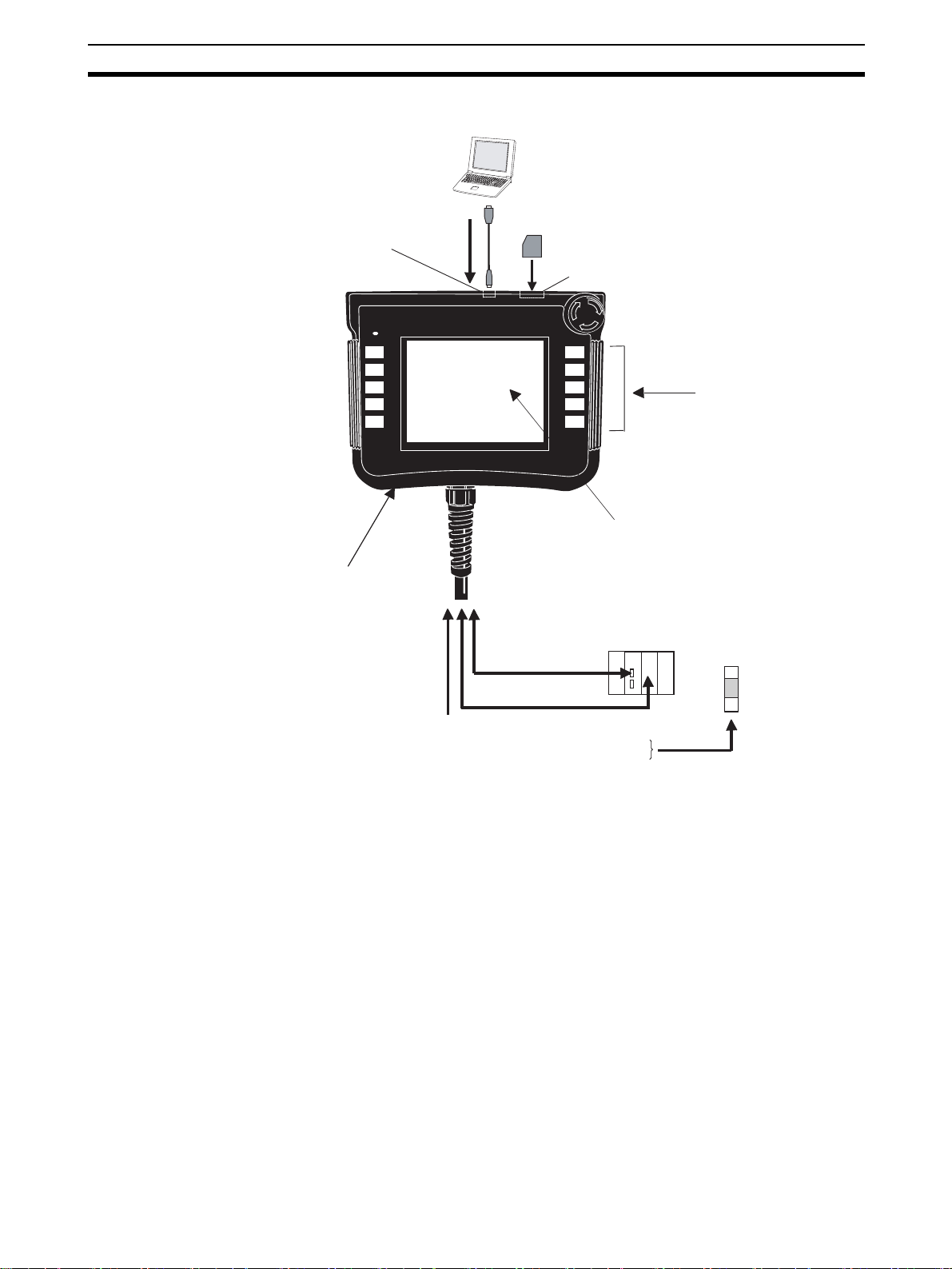
1-1-3 NSH5 Features
Computer running CX-Designer
Memory Card (Compact Flash)
USB port
RUN
F10
Screen
transfer
Memory Card slot
R
E
S
E
T
T
E
S
E
R
R
E
S
E
T
F6
F7
F8
F9
F1
F2
F3
F4
F5
Function switches (10)
Color STN LCD
Enabling switch (on back)
CS/CJ-series PLC
Safety circuits
24-VDC
power supply
Serial connection
(RS-422A/RS-232C)
1:N NT Link
External switch outputs
Function switches (F1, F2, F6, and F7)
Stop/emergency stop switch
Enabling switch
• Equipped with both a stop/emergency stop switch and an enabling switch
There are two switches provided for stopping machine operation while
using the touch panel. The stop/emergency stop switch is for stopping
operation intentionally, and the enabling switch is for stopping machine
operation without taking conscious action.
The emergency stop switch (DPST-NC contact + NO bit) is allocated one
bit in the internal memory or in the host (PLC) memory and is hard-wired
to two external outputs. It has a direct opening mechanism.
The enabling switch (3-position DPST-NO) is hard-wired to an output. It
has a direct opening mechanism, an easily confirmed click, and a rubber
cover.
• Ten function switches (SPST-NO) are provided. They can be used for
operations such as inching. Six of the function switches can be allocated
bits in internal memory or host (PLC) memory, and four of the function
switches can be output via hard-wired external outputs.
• Program-free connection is possible to an OMRON PLC via RS-232C or
RS-422A.
• A 5.7-inch STN display with 256 colors (bit maps: 4,096 colors) is provided.
3
Page 25

Overview Section 1-1
• The external end of the Special Cable (3 m, 10 m) has both a 9-pin D-Sub
male connector, and loose wires for the stop/emergency stop switch,
enabling switch, and function switches.
• Screen transfers are enabled by connecting a computer running CXDesigner to the USB port (standard feature).
• Project data can be shared with panel-mounted NS-series Programmable
Terminals.
• The Smart Active Parts library for NS-series PTs can be used.
• A Memory Card can be mounted to save screen data, data logs, operation logs, error logs, and recipes.
• The PT is waterproof to a IP65 degree of protection. (See note 1.)
• The PT withstands shock from dropping it from one meter (JIS B 3502
and IEC 61131-2). (See note 2.)
• The PT features a lightweight 1-kg hand-held design.
• The removable box is automatically detected when it’s connected.
The box number is set using the DIP switch on the removable box.
When the PT is connected, the box number is automatically detected
and the screens corresponding to the box number are automatically
displayed on the PT. At the same time, the PLC can be notified of the
box number.
Note (1) Conformance is evaluated under applicable test conditions, and it may
not be possible to use the PT in every environment. When used over a
long period of time, the drip-proof packing may become damaged or dirty
and lose its effectiveness.
(2) Conformance is evaluated under applicable test conditions, and it may
not be possible to use the PT in every environment.
1-1-4 Product Specifications
Model Specifications
NSH5-SQR00B-V2
NSH5-SQG00B-V2
NSH5-SQR10B-V2
NSH5-SQG10B-V2
5.7-inch color STN LCD
• Dots: 320 x 240
• Colors: 256 (bit maps: 4,096)
• Screen capacity
NSH5-SQ@10B-V2: 60 MB
NSH5-SQ@00B-V2: 20 MB
• 1 USB port (for transferring screen from the CX-Designer)
Commercially available USB cable can be connected.
• Memory Card: Can be mounted.
• Serial communications: Either RS-232C or RS-422A,
depending on the Special Cable used. The serial communications mode is 1:N NT Link.
• 1 stop/emergency stop switch (
DPST-NC contact + NO
bit)
• 1 enabling output (DPST-NO)
• 10 function outputs
1-1-5 Applications
4
• Setting parameters and monitoring operation when starting up equipment
or switching processes
• Setting parameters and monitoring operation when an error occurs
Page 26
Overview Section 1-1
• Setting parameters and monitoring operation anywhere in expansive facilities
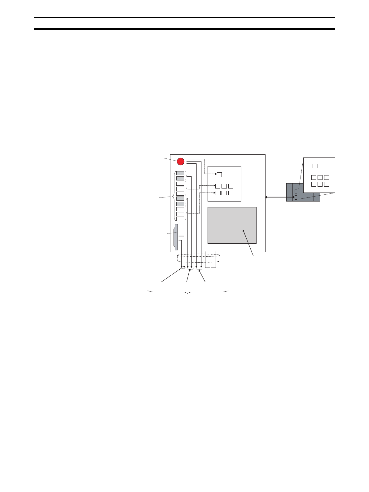
1-1-6 Switch Output Configuration
The stop/emergency stop switch uses DPST-NC contact + NO bit. Of these,
DPST-NC contacts are used for external hardware outputs. The remaining NO
bit can be allocated any bit in the internal memory or in the host (PLC) memory.
Six function switches can be allocated any bits in the internal memory or in
the host (PLC) memory. Four of the function switches can be output to external contact outputs.
The enabling switch (DPST-NO) can also be output to external contact outputs.
Stop/emergency stop switch
(DPST-NC contact + NO bit)
10 function switches
Enabling switch
(DPST-NO)
Enabling switch outputs
(DPST-NO)
The hard-wired outputs operate even when the PT power supply is OFF.
1-1-7 External Connections
Use a Special Cable (NSH5-232/422-CW-@@M, UL type: NSH5-232/422UL-
@@M), loose-wires and D-Sub connector on one end) to connect the signals
as follows:
• Emergency stop switch/stop switch
When using as a safety system, connect to safety components. (Do not
connect to the PLC.)
• Enabling switch
When using as a safety system, connect to safety components. (Do not
connect to the PLC.)
• Serial communications (RS-232C or RS-422A)
Connect to the serial port of the PLC.
• Function switches
Connect to an DC Input Unit of the PLC.
External
output
F1
F2
F3
F4
F5
F6
F7
F8
F9
F10
4 function
switch outputs
NSH5
Allocation
Internal memory
Stop/emergency stop switch
Allocation
24-VDC power supply
Stop/emergency stop
switch outputs (DPST-NC)
F3F4F8F5
F9
F10
Color STN LCD
or
RS-232C
or RS-422A
Host (PLC) memory
Stop/emergency stop switch
F3 F4
F5
F8
F9
F10
5
Page 27
Overview Section 1-1
y
R
E
S
E
T
T
E
S
E
R
R
E
S
E
RUN
F6
F7
F8
F9
F10
T
F1
F2
F3
F4
F5
Special Cable (3 or 10 m)
• RS-232C: NSH5-232@@-@@M
• RS-422A: NSH5-422@@-@@M
9-pin D-sub (male)
CS/CJ-series PLC
Safety circuits
Note (1) When used in a safety control system, the stop/emergency stop switch
and enabling switch must be connected to a safety circuit.
(2) Do not use the function switches or the touch switches on the touch panel
as emergency stop switches in situations involving potential risk to human life or serious damage.
(3) Use safety circuits that are capable of detecting shorts in the stop/emer-
gency stop switch and enable switch.
1-1-8 Safety Standards
Overview of Standards General Standards
EN 954-1
Safety-related Parts of Control Systems
Part 1: General Principles for Design
ISO Standards: ISO 13849-1; JIS Standards: JIS B 9705-1
Summary
This standard applies to design procedures for parts in control systems that
involve safety.
Function
switch outputs
Loose wires (21)
24-VDC power suppl
Safety switch
outputs
Main Point
The levels for machines are determined by taking into consideration the
degree of anticipated damage (from light to heavy) and the rate of occurrence
(from rare to frequent). The danger level is classified into five categories, and
for each category the safety functions that should be provided for control parts
are specified.
EN 60204-1
Electrical Equipment of Machines
Part 1: Specification for General Requirements
IEC Standards: IEC 60204-1; JIS Standards: JIS B 9960-1
Summary
This standard applies to electrical devices in which the power supply nominal
voltage between lines is less than 1,000 V (for AC) or 1,500 V (for DC), and
the nominal frequency is less than 200 Hz.
6
Page 28

Overview Section 1-1
Main Point
The standard covers all of the elements required in electrical devices, such as
control circuits, functions, and devices for electrical and electronic equipment,
safety measures, and technical materials related for installation, operation,
and maintenance.
Standard Related to Safety Switches
EN 60947-5-1
Low-voltage Switching Gear and Control Gear
Part 5: Control Circuit Devices and Switching Elements
Section 1: Electromechanical Control Circuit Devices
IEC Standards: IEC 60947-5-1; JIS Standards: JIS C 8201-5-1
Summary
This standard applies to switching elements and control circuit devices created for purposes such as control of switching control equipment, signals, and
interlock.
Main Points
Section 1: General Requirements
Section 2: Special Requirements for Indicator Lights
Section 3: Special Requirements for Direct Opening Operations
The standards cover topics such as switching capacity, temperature rise, ter-
minal strength, protective construction, and direct opening operations.
Standards Applicable to
the NSH5
Standard Regarding Emergency Stop Equipment
EN 418
Emergency Stop Equipment
Functional Aspects: Principles for Design
ISO Standards: ISO 13850; JIS Standards: JIS B 9703
Summary
This standard prescribes the design principles for emergency stop equipment.
Main Points
A direct opening mechanism must be provided.
A self-holding mechanism must be provided.
The stopping device must be in a form that is easy to operate, such as a pro-
truding pushbutton, a wire, or a rope.
The stopping device must be red with a yellow background.
The following safety standards apply to the NSH5 PT.
• Based on EN 60204-1
• Complies with EN 954-1
EN 60204-1 Safety Standard
IEC204-1 (EN60204-1: Electrical Safety Standard for Machinery) stipulates
that an emergency stop switch must be red, and a stop switch must be gray or
black. When detaching and using the PT separate from the system, always
use a PT with a gray switch.
In the EN60204-1safety standard, emergency stop and emergency shutdown
are defined as emergency switches.
Emergency stop Stop category 0 or 1
Emergency shutdown Stop category 0 only
7
Page 29
Nomenclature and Functions Section 1-2
It is stipulated in EN 60204-1 that the pushbutton for an emergency stop must
be red and the background yellow. In SEMI-S2 as well, the background for an
emergency shutdown pushbutton must be yellow.
To comply with these standards, a yellow seal is included with the product to
affix around the emergency stop switch.
EN 954-1 General Design Principles
Redundant conformity is provided with an enabling switch and an emergency
stop switch. The emergency stop switch is a three-pole switch (3PST-NC),
with a DPST-NC contact structure and a SPST-NC contact structure for an
emergency stop notification signal.
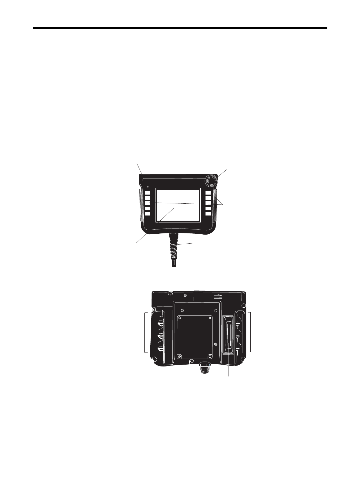
1-2 Nomenclature and Functions
1-2-1 Front
LED indicator
Stop/emergency stop switch
R
E
S
E
T
T
E
S
E
R
R
E
S
E
RUN
F6
F7
F8
F9
F10
T
F1
F2
F3
F4
F5
Function switches
F1, F2, F6, and F7 are hard-wired outputs.
F3, F4, F5, F8, F9, and F10 are software
(communications) outputs.
1-2-2 Back
5.7-in. STN
Hand holds
Cable
Loose wires and RS-232C cable (3 or 10 m)
Loose wires and RS-422A cable (10 m)
Hand holds
Enabling switch
8
Page 30

Nomenclature and Functions Section 1-2
t
1-2-3 Top
Memory Card slot
USB por
Display Section Effective display area: 5.7 inches
Liquid crystal: Color STN LCD with backlight
Number of dots: 320 × 240
Number of display colors: 256 (BMP/JPG images: 4,096)
RUN Indicator The NSH5 status indicator is described in the following table.
Color
RUN
Indicator
Lit Normal operation • Checking file system
Flashing • Memory Card transfer
• Backlight error discov-
Not lit • Power is not being supplied.
• A fuse is burned out.
• A system program is damaged and cannot boot.
Green Orange Red
at startup.
• Normal operation
with battery voltage
low or battery disconnected.
completed normally.
ered after startup.
Memory Card transfer
in progress.
Error occurred at
startup.
Error occurred during Memory Card
transfer.
Switch Section OMRON A165E-S-03U Stop/Emergency Stop Switch
DPST-NC contact: External output
Rated voltage: 24 V
Maximum rated current: 100 mA (minimum applicable load: 1 mA at 5 VDC)
NO bit: Allocated in internal memory or host (PLC)
OMRON A4E-B200VA Enabling Switch
DPST-NO contact: External output
Rated voltage: 24 V
Maximum rated current: 100 mA (minimum applicable load: 4 mA at 24 VDC)
3-position switch
Operating patterns:
Operation: OFF to ON to OFF
Reset: OFF to ON, momentary 3-position operation
9
Page 31

Special Cable Specifications Section 1-3
Function Switches
F1, F2, F6, and F7: External outputs
Rated voltage: 24 V
Maximum rated current: 50 mA
F3, F4, F5, F8, F9, and F10: Allocated bits in internal memory or host (PLC)
Memory Card Section A Memory Card is mounted here.
Model Capacity Memory type
HMC-EF183 128 MB Flash memory
HMC-EF283 256 MB Flash memory
HMC-EF583 512 MB Flash memory
Screen data, data logs, operation logs, error logs, and recipes can be saved.
USB Port The USB port is connected to a computer using a commercially available USB
cable, and used to transfer screens.
Serial Communications
Port
The serial port is used for RS-232C or RS-422A communications through the
Special Cable.
Serial communication mode: NT link (1:N mode)
Special Cable Connectors
(Inside Back Cover)
CN1: 24-VDC power supply inputs
CN2: Serial interface.
CN3: External outputs.
1-3 Special Cable Specifications
1-3-1 Special Cable Models
Loose-wire/D-Sub, UL-standard, and Removable Box Cables are available.
Cables are provided for both RS-232C and RS-422A depending on the serial
communications protocol.
Cable type Communications
Loose-wire/
D-Sub
UL-standard Loose wires +
Removable
Box
connector
9-pin D-Sub +
Loose wires
9-pin D-Sub +
Loose wires
relay cable
Loose wires
37-pin D-Sub
Serial
communications
RS-232C NSH5-232CW-3M 3 m
RS-422A NSH5-422CW-10M 10 m
RS-232C NSH5-232UL-3M 3 m
RS-422A NSH5-422UL-10M 10 m
RS-232C NSH5-232CN-3M 3 m
Model Length
NSH5-232CW-10M 10 m
NSH5-232UL-10M 10 m
NSH5-232CN-10M 10 m
Note
Always use a UL-standard Cables for applications requiring UL certification.
1-3-2 UL-standard Cable
Wiring Hard-wired Signals The function keys and the emergency stop switch are directly connected via
the connecting cable to the PLC or device I/O terminals.
10
Page 32

Special Cable Specifications Section 1-3
r
Wiring the Serial
Communication Line
Cable Dimensions
Depending on the type of cable, there are two types of serial communications
wiring: RS-232C connector and RS-422A connector. The RS-232C type
comes equipped with a relay cable. This type can connected to the RS-232C
port of the OMRON SYSMAC CS/CJ series PLC. The RS-422A type has a
loose-wire connector, and the signal must be converted by the
Conversion Unit, then connected to the
RS-232C port of the OMRON SYS-
MAC CS/CJ series PLC.
NSH5-232UL-3M/10M
•
16
15
CN5
(30)
•
20
19
CN8
Loopback connector
CN1
•
1
2
CN2
•
3
4
CN3
•
5
6
7L30 dia.
232C Relay cable
•
21
22
(30)
23
±30
1,000
80±10
7L30 dia.
70±10
When connecting to an OMRON PLC, the control signals must be looped back.
Connect loopback connectors to CN8 and CN7.
CN6
•
1817
(30)
26
8
7
9
NSH5....
10
•
12
11
L
300±10
200±10
25
7L30 dia.
CJ1W-CIF11
24
CN4
•
13
14
CN7
•
21
22
Loopback connecto
•
19
20
P4/7
No. Circuit
Product name Model Maker
Quantity
Unit
symbol
1 CN1 Housing DF3-3S-2C HRS 1 Piece
2 CN1 Crimp terminal DF3-2428SCFC HRS 3 Piece
3 CN2 Housing SHDR-20V-S-B JST 1 Piece
4 CN2 Crimp terminal SSH-003GA-P0.2 JST 8 Piece
5 CN3 Housing DF11-18DS-2C HRS 1 Piece
6 CN3 Crimp terminal DF11-2428SCFA HRS 18 Piece
7 Heat-shrinkable
tube
SUMITUBE FS (Z), 14-mm dia.,
black
Sumitomo 0.06 m
8 Packing GMP-20 LAPP 1 Piece
9 Housing BS-M20 × 1.5 LAPP 1 Piece
10 Cable 2464 composite, 27-conductor,
shield
BANDO
ELECTRIC
Lm
WIRE
11 Housing ST-PG16 LAPP 1 Piece
12 Lock nut GMK-16 LAPP 1 Piece
13 CN4 Housing SMR-04V-N JST 1 Piece
14 CN4 Crimp terminal SYM-001T-p0.6 JST 4 Piece
15 CN5 Housing SMP-04V-NC JST 1 Piece
16 CN5 Crimp terminal SHF-001T-0.8BS JST 4 Piece
11
Page 33

Special Cable Specifications Section 1-3
4
No. Circuit
Product name Model Maker
Quantity
Unit
symbol
17 CN6 D-Sub 9-pin plug XM2A-0901 OMRON 1 Piece
18 CN6 D-Sub 9-pin hood XM2S-0911 OMRON 1 Piece
19 CN7 Housing SMR-02V-N JST 2 Piece
20 CN7 Crimp terminal SYM-001T-p0.6 JST 4 Piece
21 CN8 Housing SMP-02V-NC JST 2 Piece
22 CN8 Crimp terminal SYM-001T-p0.6 JST 4 Piece
23 Cable BIOS-A-2805P BANDO
1m
ELECTRIC
WIRE
24 Crimp terminal 0.5-3.7A JST 21 Piece
25 Heat-shrinkable
cable
SUMITUBE F (Z), 2-mm dia.,
white
Sumitomo m
26 Label NSH5-232UL-10M·LOT No. 1Piece
NSH5-422UL-10M
CN1
•
1
2
•
3
Shorted by
connector
•
5
6
CN2
4
CN3
7L30 dia.
(30)
15
80±10
(30)
8
7
9
16
NSH5....
10
•
12
11
(30)
7
300±10
CN
13
14
No. Circuit
70±10
Product name Model Maker
L
Quantity
Unit
symbol
1 CN1 Housing DF3-3S-2C HRS 1 Piece
2 CN1 Crimp terminal DF3-2428SCFC HRS 3 Piece
3 CN2 Housing SHDR-20V-S-B JST 1 Piece
4 CN2 Crimp terminal SSH-003GA-P0.2 JST 8 Piece
5 CN3 Housing DF11-18DS-2C HRS 1 Piece
6 CN3 Crimp terminal DF11-2428SCFA HRS 18 Piece
7 Heat-shrinkable
tube
SUMITUBE F2 (Z), 14-mm dia.,
black
Sumitomo 0.06 m
8 Packing GMP-20 LAPP 1 Piece
9 Housing BS-M20 × 1.5 LAPP 1 Piece
10 Cable 2464 composite, 27-conductor,
shield
BANDO
ELECTRIC
Lm
WIRE
11 Housing ST-PG16 LAPP 1 Piece
12 Lock nut GMK-16 LAPP 1 Piece
13 Crimp terminal 0.5-3.7A JST 29 Piece
14 Heat-shrinkable
cable
15 Cable UL1061# 28 black Piece
16 Label NSH5-232UL-10M·LOT No. 1Piece
SUMITUBE F (Z), 2-mm dia.,
white
Sumitomo m
12
Page 34

Special Cable Specifications Section 1-3
RS-232C Wiring
CN1
Signal
FG
1
2
0 V
3
24 V
CN3
1
F1
2
F2
3
F6
F7
4
5
SWCOM
6
EMG1A1
7
EMG1A2
8
EMG2A1
EMG2A2
9
10
ENB1A1
ENB1A2
11
12
ENB2A1
13
ENB2A2
0 V (SG) 0 V (SG)
14
15
16
17
18
S4
S3
S2
S1
CN2 CN4
Pin No. Signal
1
SD
2
RD
3
RS
4
CS
5
NC
6
0 V (SG)
7
NC
8
NC
9
SDB+
10
SDA-
11
RDB+
12
RDA-
13
RSB+
14
RSA-
15
16
17
18
19
20
FG
NC
NC
NC
NC
NC
Pin No.
Pin No. SignalPin No. Signal Wire size
Forked
terminal
Forked
terminal
Forked
terminal
Forked
terminal
Forked
terminal
Forked
terminal
Forked
terminal
Forked
terminal
Forked
terminal
Forked
terminal
Forked
terminal
Forked
terminal
Forked
terminal
Forked
terminal
Forked
terminal
Forked
terminal
Forked
terminal
Forked
terminal
Forked
terminal
Forked
terminal
Forked
terminal
SignalPin No.
24 V
SWCOM
EMG1A1
EMG1A2
EMG2A1
EMG2A2
ENB1A1
ENB1A2
ENB2A1
ENB2A2
FG
0 V
F1
F2
F6
F7
S4
S3
S2
S1
Wire size
Outer shield
AWG2 4
AWG2 4
AWG2 8
AWG2 8
AWG2 8
AWG2 8
AWG2 8
AWG2 8
AWG2 8
AWG2 8
AWG2 8
AWG2 8
AWG2 8
AWG2 8
AWG2 8
AWG2 8
AWG2 8
AWG2 8
AWG2 8
AWG2 8
Pin No.
1
2
3
4
CN7
Pin No.
1
2
13
Page 35

Special Cable Specifications Section 1-3
CN6CN5
RD
SD
SG
FG
Wire size
AWG2 8
AWG2 8
AWG2 8
AWG2 8
Pin No. Signal
1
2
3
4
UL1061, #28, black
Pin No.
3
2
9
Case
RS-422A Wiring
CN1
CN3
CN8
Pin No.
1
2
CN4
FG
1
2
0 V
3
24 V
CN4
1
2
3
4
5
6
7
8
9
10
11
12
13
14
15
16
17
18
F1
F2
F6
F7
SWCOM
EMG1A1
EMG1A2
EMG2A1
EMG2A2
ENB1A1
ENB1A2
ENB2A1
ENB2A2
0 V (SG) 0 V (SG)
S4
S3
S2
S1
3
NC
4
5
CS
7
NC
Pin No.Signal Wire sizePin No. Signal
Forked
terminal
Forked
terminal
FG
0 V
24 V
Pin No.Signal Wire sizePin No. Signal
Forked
terminal
Forked
terminal
Forked
terminal
Forked
terminal
Forked
terminal
Forked
terminal
Forked
terminal
Forked
terminal
Forked
terminal
Forked
terminal
Forked
terminal
Forked
terminal
Forked
terminal
Forked
terminal
Forked
terminal
Forked
terminal
Forked
terminal
Forked
terminal
F1
F2
F6
F7
SWCOM
EMG1A1
EMG1A2
EMG2A1
EMG2A2
ENB1A1
ENB1A2
ENB2A1
ENB2A2
S4
S3
S2
S1
---
---RS
---
---
Outer shield
AWG2 4
AWG2 4
AWG2 8
AWG2 8
AWG2 8
AWG2 8
AWG2 8
AWG2 8
AWG2 8
AWG2 8
AWG2 8
AWG2 8
AWG2 8
AWG2 8
AWG2 8
AWG2 8
AWG2 8
AWG2 8
AWG2 8
AWG2 8
14
Page 36

Special Cable Specifications Section 1-3
1-3-3 Loose-wire/D-Sub Cable
Wiring Hard-wired Signals
The function keys and the emergency stop switch are directly connected via
the connecting cable to the PLC or device I/O terminals.
CN2
Pin No. Signal
1
2
3
4
5
6
0 V (SG)
7
Loop_Close
8
Loop_Close
9
SDB+
10
SDA−
11
RDB+
12
RDA−
13
RSB+
14
RSA−
15
16
17
18
19
20
SD
RD
RS
CS
NC
FG
NC
NC
NC
NC
NC
CN4
Pin No. Signal
Forked
0 V (SG)
terminal
7
8
Forked
terminal
Forked
terminal
Forked
terminal
Forked
terminal
Forked
terminal
Forked
terminal
Forked
terminal
3
4
5
7
--- ---
--- ---
SDB+
SDA−
RDB+
RDA−
RSB+
RSA−
Inner shield
FG
--- ---
--- ---
--- ---
--- ---
Wire size
AWG2 8
AWG2 8
AWG2 8
AWG2 8
AWG2 8
AWG2 8
AWG2 8
Cable Dimensions
Wiring the Serial Communications Line
Depending on the type of cable, there are two types of serial communications
wiring: RS-232C connector and RS-422A connector. For RS-232C or RS422A connector, the connector is a 9-pin male D-Sub connector and can be
directly connected to the RS-232C or RS-422A port of an OMRON SYSMAC
CS/CJ-series PLC.
A conversion cable must be prepared in order to connect to any other host.
+15
+5
80
CN1
AB
CN2
CN
CD
CN3
EF
1
3
0
I
G
35
+5
70
0
H
+300
10,000
−300
J
No. Product name Model Maker Quantity
A Pressure-welded
DF3-3S-2R26(01) HRS 1
socket
B Socket crimp ter-
DF3-2428SCC HRS 3
minal
300
G
+10
35
100
0
0
L
No.5
No.10
No.1
K
CN4
No.6
15
Page 37

Special Cable Specifications Section 1-3
No. Product name Model Maker Quantity
C Housing SHDR-10V-S-B-LF-SN J.S.T. Mfg. Co. 1
D Contact SSH-003GA-P0.2-LF-SN J.S.T. Mfg. Co. 8
E Crimp socket DF11-18DS-2C HRS 1
RS-232C Wiring
F Socket crimp ter-
minal
G Heat-shrinkable
tube
H Packing GPM20 LAPP KABLE 1
I Housing (black) BS-M20 × 1.5 LAPP KABLE 1
J Cable UL20233-SLB (black)
K Forked terminal --- --- 21
L 9-pin D-Sub plug XM2A-09 OMRON 1
M 9-pin D-Sub hood XM2S-09 OMRON 1
CN1
Pin No. Signal
1
2
FG
0 V
3 24 V
CN3
Pin No. Signal Pin No. Signal Wire size
1
2
3
4
5
6
7
8
9
10
11
12
13
14
15
16
17
18
F1
F2
F6
F7
SWCOM
EMG1A1
EMG1A2
EMG2A1
EMG2A2
ENB1A1
ENB1A2
ENB2A1
ENB2A2
0 V (SG)
S4
S3
S2
S1
DF11-2428SCA HRS 18
Sumi-tube Sumitomo 1
LAPP KABLE 1
2Cx#24+4Px#28+26Cx#
28
Pin No. Signal Wire size
Forked terminal
Forked terminal
Forked terminal
Forked terminal
Forked terminal
Forked terminal
Forked terminal
Forked terminal
Forked terminal
Forked terminal
Forked terminal
Forked terminal
Forked terminal
Forked terminal
Forked terminal
Forked terminal
Forked terminal
Forked terminal
Forked terminal
Forked terminal
Forked terminal
FG
0 V
24 V
F1
F2
F6
F7
SWCOM
EMG1A1
EMG1A2
EMG2A1
EMG2A2
ENB1A1
ENB1A2
ENB2A1
ENB2A2
0 V (SG)
S4
S3
S2
S1
Shield
AWG24
AWG24
AWG28
AWG28
AWG28
AWG28
AWG28
AWG28
AWG28
AWG28
AWG28
AWG28
AWG28
AWG28
AWG28
AWG28
AWG28
AWG28
AWG28
AWG28
16
Page 38

Special Cable Specifications Section 1-3
RS-422A Wiring
CN2
Pin No. Signal
1
2
3
4
5
6
7
8
9
10
11
12
13
14
15
16
17
18
19
20
SD
RD
RS
CS
NC
0 V (SG)
Loop_Open
Loop_Open
SDB+
SDA−
RDB+
RDA−
RSB+
RSA−
FG
NC
NC
NC
NC
NC
CN4 (9-pin D-Sub)
Pin No. Signal Wire size
3
2
4
5
9
Hood
1
6
7
8
RD
SD
RS
CS
SG (0 V)
FG
NC
NC
NC
NC
AWG28
AWG28
AWG28
AWG28
AWG28
Shield
CN1
Pin No. Signal Pin No. Signal Wire size
1
2
FG
0 V
3 24 V
Forked terminal
Forked terminal
Forked terminal
FG
0 V
24 V
Shield
AWG24
AWG24
CN3
Pin No. Signal Pin No. Signal Wire size
F1
F2
F6
F7
SWCOM
EMG1A1
EMG1A2
EMG2A1
EMG2A2
ENB1A1
ENB1A2
ENB2A1
ENB2A2
0 V (SG)
S4
S3
S2
S1
AWG28
AWG28
AWG28
AWG28
AWG28
AWG28
AWG28
AWG28
AWG28
AWG28
AWG28
AWG28
AWG28
AWG28
AWG28
AWG28
AWG28
AWG28
10
11
12
13
14
15
16
17
18
1
2
3
4
5
6
7
8
9
F1
F2
F6
F7
SWCOM
EMG1A1
EMG1A2
EMG2A1
EMG2A2
ENB1A1
ENB1A2
ENB2A1
ENB2A2
0 V (SG)
S4
S3
S2
S1
Forked terminal
Forked terminal
Forked terminal
Forked terminal
Forked terminal
Forked terminal
Forked terminal
Forked terminal
Forked terminal
Forked terminal
Forked terminal
Forked terminal
Forked terminal
Forked terminal
Forked terminal
Forked terminal
Forked terminal
Forked terminal
17
Page 39

Special Cable Specifications Section 1-3
CN2
Pin No. Signal
1
2
3
4
5
6
7
8
9
10
11
12
13
14
15
16
17
18
19
20
SD
RD
RS
CS
NC
0 V (SG)
Loop_Close
Loop_Close
SDB+
SDA−
RDB+
RDA−
RSB+
RSA−
FG
NC
NC
NC
NC
NC
CN4 (9-pin D-Sub)
Pin No. Signal
SG (0 V)
9
8
6
2
1
Hood
3
4
5
7
SDB+
SDA−
RDB+
RDA−
FG
NC
NC
NC
NC
Wire size
AWG28
AWG28
AWG28
AWG28
AWG28
Shield
18
Page 40

Special Cable Specifications Section 1-3
4
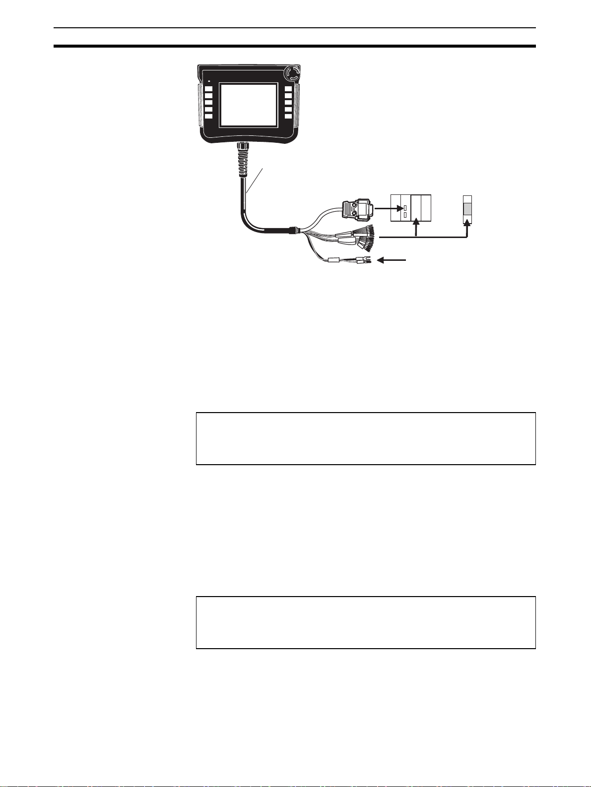
1-3-4 Removable Box Cable
Wiring Hard-wired Signals
The function keys and the emergency stop switch are connected through the
Removable Box connected via the Removable Box Cable and output to safety
circuits or other circuits connected to the hard-wired terminal block.
Wiring the Serial Communications Line
There is only one type of RS-232C connector. It is a 37-pin male D-Sub connector and can be directly connected to the RS-232C port on the NSH5AL001 Removable Box.
Cable Dimensions
NSH5-232CN-3M/10M
CN1
1
CN2
3
CN3
5
•
2
•
4
(30)
•
6
80±10
7L30 dia.
70±10
(30)
14
8
7
9
L
10
NSH5....
10±5
7
11
••
12 15
CN
No. Circuit
Product name Model Maker
Quantity
Unit
symbol
1 CN1 Housing DF3-3S-2C HRS 1 Pieces
2 CN1 Crimp Terminal DF3-2428SCFC HRS 3 Pieces
3 CN2 Housing SHDR-20V-S-B JST 1 Pieces
4 CN2 Crimp Terminal SSH-003GA-P0.2 JST 8 Pieces
5 CN3 Housing DF11-18DS-2C HRS 1 Pieces
6 CN3 Crimp Terminal DF11-2428SCFA HRS 18 Pieces
7 Heat-shrinkable
Tu be
SUMITUBE F2 (Z), 14-mm dia.,
black
Sumitomo 0.06 m
8 Packing GMP-20 LAPP 1 Pieces
9 Housing BS-M20 × 1.5 LAPP 1 Pieces
10 Cable 2464 composite, 27-conductor,
shield
Bando Electric Wire
Lm
11 CN4 D-SUB37P Plug XM2A3701 OMRON 1 Pieces
12 CN4 D-SUB37P Hood XM2A3711 OMRON 1 Pieces
13 Cable UL1061AWG28 yellow Kyowa Elec-
0.06 m
tronic
Instruments
14 Label NSH5-232CN-3M·LOT No. 1Pieces
15 Jack Screw XM2Z-0071 OMRON 2 Pieces
19
Page 41

Special Cable Specifications Section 1-3
RS-232C Wiring
CN1
Pin No.
1
2
3
Signal
FG
0 V
24 V
CN4
Pin No. Signal Wire size
37
18
19
FG
0 V
24 V
Outer shield
AWG24
AWG24
CN3
Pin No. Signal
1
F1
2
F2
3
F6
4
F7
5
SWCOM
6
EMG1A1
7
EMG1A2
8
EMG2A1
9
EMG2A2
10
ENB1A1
11
ENB1A2
12
ENB2A1
ENB2A2
13
14
0 V (SG)
15
16
17
18
S4
S3
S2
S1
CN2
Pin No. Signal
1
2
3
4
5
0 V (SG)
6
7
8
9
10
11
12
13
14
15
16
17
18
19
20
SD
RD
RS
CS
FG
CN4
Pin No. Signal Wire size
11
30
10
29
9
15
34
16
35
13
32
14
33
3
21
20
2
1
4
22
F1
F2
F6
F7
SWCOM
EMG1A1
EMG1A2
EMG2A1
EMG2A2
ENB1A1
ENB1A2
ENB2A1
ENB2A2
0 V (SG)
S4
S3
S2
S1
CONECT1
CONECT2
AWG28
AWG28
AWG28
AWG28
AWG28
AWG28
AWG28
AWG28
AWG28
AWG28
AWG28
AWG28
AWG28
AWG28
AWG28
AWG28
AWG28
AWG28
CN4
Pin No. Signal Wire size
Hood
SD
7
RD
6
RS
25
CS
26
0 V (SG)
24
Inner shield
FG
20
Page 42
Special Cable Specifications Section 1-3
3
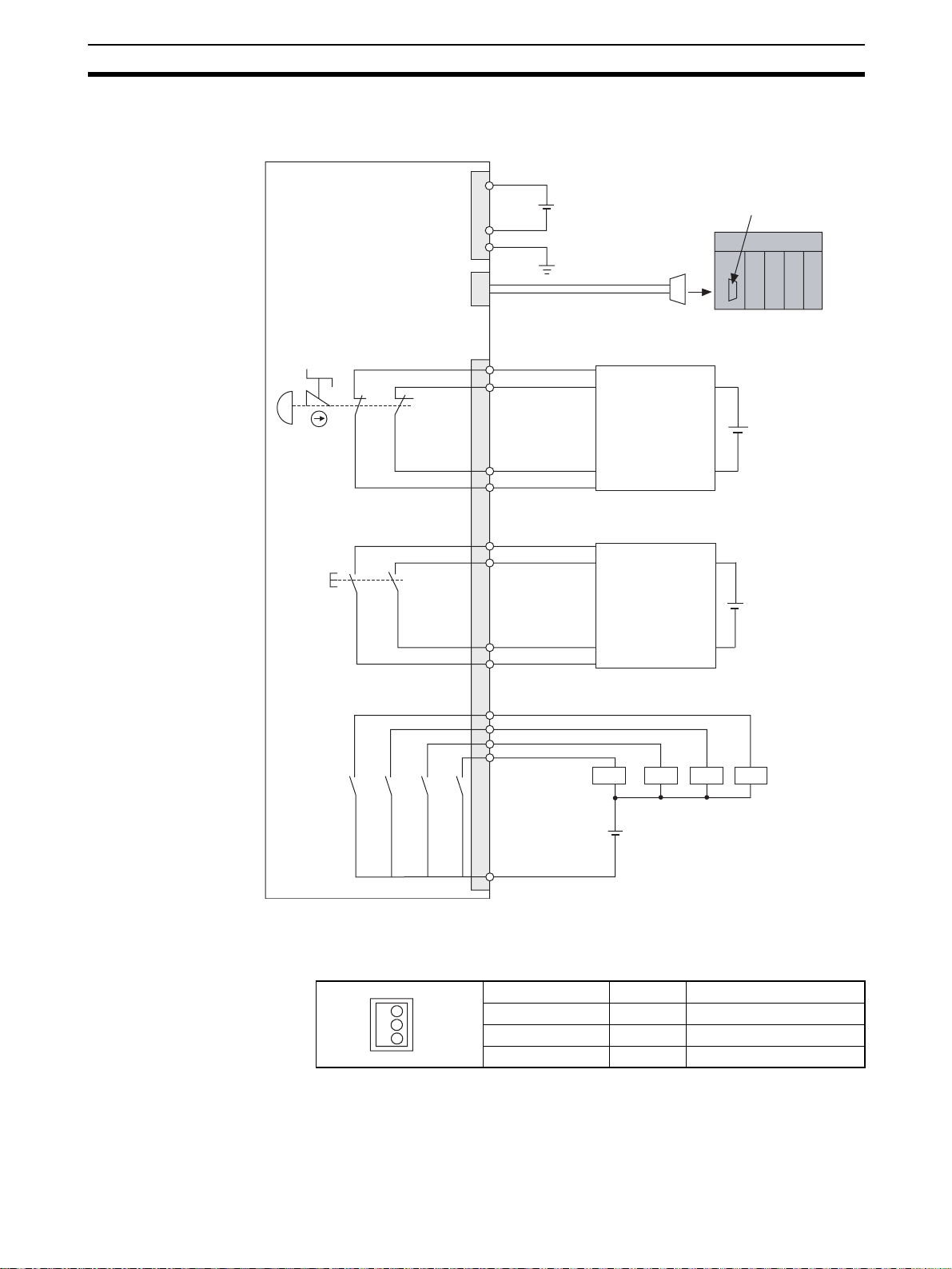
1-3-5 External Wiring Diagram
NSH5
24 V
Emergency stop switch
DPST-NC
CN1
For 24-VDC power
supply input
CN2
For serial interface
CN3
For external outputs
0 V
FG
RS-232C: SD: Pin 2; RD: Pin 3, pins 4 and 5 short-circuited; FG: Connector hood
RS-422A: SDA(+): 1; SDB(+): 2; RDA(-): Pin 6; RDB(+): Pin 8; FG: Connector hood
EMG1A1
EMG2A1
24 VDC
Serial port on PLC
EMG2EMG1
Enabling switch
DPST-NO
Function switches
Four NO contacts to external devices
ENB1
ENB2
F1F2F2F6F6F7F7
Safety circuit
EMG2A2
EMG1A2
ENB2A1
ENB2A1
Safety circuit
ENB2A2
ENB1A2
F1
PLC PLC PLC PLC
SW COM
1-3-6 Interface Specifications
24-VDC Interface (CN1)
Pin No. Signal Contents
2
1 FG Frame ground
2 0 V 0-V power supply input
3 24 VDC +24-V power supply input
21
Page 43

Special Cable Specifications Section 1-3
Serial Interface RS-232C/
422A (CN2)
20
2
Pin No. Signal Contents
1 SD Send Data
2 RD Receive Data
3 RS Request Send
4 CS Clear to Send
5 NC Not connected
60 V (SG)0 V
7 Loop Close Loop Close
8 Loop Close Loop Close
19
9 SDB+ Send Data B
10 SDA− Send Data A
11 RDB+ Receive Data B
1
12 RDA− Receive Data A
13 RSB+ Not connected
14 RSA− Not connected
15 FG Hood
16 NC Not connected
17 NC Not connected
18 NC Not connected
19 NC Not connected
20 NC Not connected
External Output Interface
(CN3)
Note For details on station numbers, refer to 3-8 Station Detection Function.
Pin No. Signal Contents
1 F1 Function switch F1
2 F2 Function switch F2
3 F6 Function switch F6
4 F7 Function switch F7
5 SWCOM Function switch common
6 EMG1 A1 Stop/emergency stop switch line 1
12
7 EMG1 A2 Stop/emergency stop switch line 1
8 EMG2 A1 Stop/emergency stop switch line 2
9 EMG2 A2 Stop/emergency stop switch line 2
10 ENB1 A1 Enabling switch line 1
18
17
11 ENB1 A2 Enabling switch line 1
12 ENB2 A1 Enabling switch line 2
13 ENB2 A2 Enabling switch line 2
14 0 V (SG) Station ID line 0 V
15 S4 Station ID line 4
16 S3 Station ID line 3
17 S2 Station ID line 2
18 S1 Station ID line 1
22
Page 44

SECTION 2
Grounding and Connections
This section describes wiring and grounding the power supply and how to connect the NSH5 Programmable Terminal using
the Special Cable.
2-1 Installation Environment. . . . . . . . . . . . . . . . . . . . . . . . . . . . . . . . . . . . . . . . . 24
2-2 Power Supply and FG Wiring . . . . . . . . . . . . . . . . . . . . . . . . . . . . . . . . . . . . . 24
2-2-1 Power Supply Wiring . . . . . . . . . . . . . . . . . . . . . . . . . . . . . . . . . . . . 24
2-2-2 FG Wiring. . . . . . . . . . . . . . . . . . . . . . . . . . . . . . . . . . . . . . . . . . . . . 25
2-3 Connecting the Special Cable . . . . . . . . . . . . . . . . . . . . . . . . . . . . . . . . . . . . . 26
2-4 Attaching the Hand Strap . . . . . . . . . . . . . . . . . . . . . . . . . . . . . . . . . . . . . . . . 31
2-5 Installing the Mounting Bracket . . . . . . . . . . . . . . . . . . . . . . . . . . . . . . . . . . . 31
23
Page 45

Installation Environment Section 2-1
2-1 Installation Environment
Observe the following precautions when installing an NSH5 Programmable
Terminal.
Precautions Do not install the PT in the following locations.
• Locations subject to severe changes in temperature
• Locations subject to temperatures or humidity outside the range specified
in the specifications
• Locations subject to condensation as a result of severe changes in temperature
• Locations subject water, oil, or chemical spray
• Locations subject to corrosive or flammable gases
• Locations subject to shock or vibration
• Locations outdoors directly subject to wind or rain
• Locations subject to strong ultraviolet light
Take appropriate and sufficient countermeasures when installing systems in
the following locations.
• Locations subject to static electricity or other forms of noise
• Locations subject to strong electromagnetic fields
• Locations close to power lines
• Locations subject to possible exposure to radioactivity
Note Before unpacking the PT or Peripheral Devices, look the product over and
check for any damage. Gently shake the product and listen for any abnormal
sounds.
2-2 Power Supply and FG Wiring
2-2-1 Power Supply Wiring
Connect a 24-VDC power supply to the power supply input terminals. The following table shows the specifications for the power supply that can be connected. Determine the power supply specifications so that the power supply
capacity is satisfied.
Item Specifications
Power supply voltage 24 VDC
Allowable power supply voltage
fluctuation range
Power supply capacity 10 W min.
Wire the power supply input terminals to the 24-VDC power supply as shown
below.
24 VDC
(Functional ground)
20.4 to 27.6 VDC (24 VDC
±15%)
24
24-VDC interface at NSH5
Note (1) Do not connect an AC power supply to the power supply terminals.
Page 46

Power Supply and FG Wiring Section 2-2
(2) Use a DC power supply with little voltage fluctuation.
(3) Do not perform a dielectric strength test.
(4) To comply with the Low-voltage Directive in the EC Directives, use a pow-
er supply with reinforced insulation. Reinforced insulation is a single insulation method that can protect against electrical shock to the same
degree as double insulation.
Recommended model: S82K-03024 (manufactured by OMRON)
(5) Insert a 3-A fuse immediately after the secondary output from the power
supply.
(6) To comply with UL-recognized standards, always use a Class 2 power supply. A
Class 2 power supply refers to one in which the current and voltage levels
of the product’s secondary output are both limited (100 VA max.), and
which has undergone and passed the necessary tests for UL certification.
2-2-2 FG Wiring
The cable connected to the PT has a functional ground terminal (FG)
Wire them according to the conditions described below.
1,2,3... 1. If there is a ground potential difference between the NSH5 and the host,
install them as shown in the following diagram.
Do not ground the PT if there is a distance between the PT and the ground
and one-point grounding is difficult.
2. If the PT is installed in the same panel as a source of noise, such as a motor or an inverter, do not ground the PT.
NSH5
Host
One-point grounding
Note Be sure to ground correctly to prevent malfunctioning due to noise.
25
Page 47
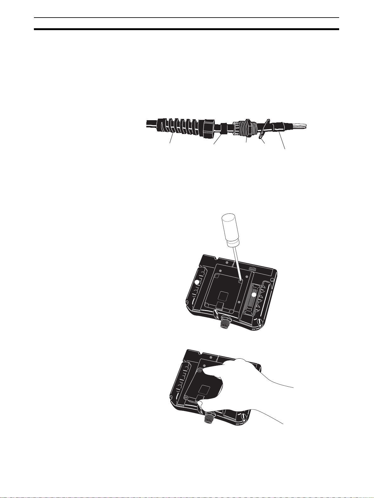
Connecting the Special Cable Section 2-3
2-3 Connecting the Special Cable
This section describes how to connect the Special Cable to the PT.
Check before Connecting
1,2,3... 1. Waterproof cable clamps are attached to both ends of the Special Cable.
The cable has inner and outer waterproof packing. The packing is important to maintain the cables waterproof capabilities, so be sure it is not lost
or damaged.
NSH5 PT Cable Clamp
Connection Procedure
1,2,3... 1. Using a screwdriver, loosen the four screws on the PT back cover.
Cable attachment
cap
Cable
packing
Unit lock
housing
Packing
Heat-shrinking
tube
2. Be sure the cable clamp housing is not damaged or dirty before inserting
it into the PT. If the housing is damaged, have it repaired to retain the waterproof capabilities.
26
2. After the screws have been removed, grasp the cover by the hand holds
and lift it out.
Page 48

Connecting the Special Cable Section 2-3
3. When the cover has been removed and the back of the PT is open, the
I/O connector and interface on the board in the PT can be seen.
ON
DIP Switch
DIP switch pins are ON
when set to the right.
Battery interface
Serial interface
External output interface
24-VDC interface
4. Using your hand, lightly tighten the waterproof packing while it is attached
to the housing. Then use a wrench to tighten the waterproof packing to a
force of 4.0 to 6.0 N·m to secure it in place.
5. Insert the cable into the PT until the heat-shrinking tube is visible on the
inside.
Heat-shrinking tube
6. Insert the cable packing into the inside of the cable clamp housing and
lightly tighten the cap by hand.
Cable packing
27
Page 49

Connecting the Special Cable Section 2-3
Insert the Special
Cable into the PT.
7. Tighten the cap with a wrench to a force of 2.0 to 3.0 N·m to ensure that
the cable will not easily come loose if pulled.
Note Inspect the cable periodically to see if it has become loose.
8. Connect each connector as shown below.
1
O
N
2
3
4
28
Page 50

Connecting the Special Cable Section 2-3
Be sure to correctly connect the connectors as shown in the following diagram.
Serial interface: White, 20-pin connector
24-VDC power supply interface: Black, 3-pin connector
External output interface: Black, 18-pin connector
Serial interface
External output interface
24-VDC interface
9. When using RS-422A communications, turn ON DIP switch pin 1 (terminating resistance ON) only when the PT is wired as the end communications node.
Note DIP switch pin 1 connects and disconnect the terminating resistance. Always
leave pins 2 to 4 turned OFF (default setting).
10. Replace the cover, insert the four mounting screws, and tighten them to a
force of 0.4 N·m.
29
Page 51

Connecting the Special Cable Section 2-3
Mounting to a Control
Panel
1,2,3... 1. When using a UL-standard cable, it is necessary to cut a hole in the control
A UL-standard cable connection example is given below.
panel to secure the cable clamp.
Cable Clamp Mounting Hole Dimension
23±0.2 mm
2. Feed the UL-standard cable through the hole, then secure the cable clamp
to the control panel from the inside using the lock nut. When using the
NSH5-232UL-3M/10M, always connect the relay cable, which is equipped
with an RS-232C connector, after feeding the UL-standard cable through
the hole in the wall of the control panel. Tighten the lock nut to a force of
2.0 to 3.0 N·m.
Cable
Cap
packing
Housing
Lock nut
Cut a cable clamp mounting hole in
the control panel, using the cable
diameter as a guide, then feed the
Control panel
Adjust the cable length,
place the rubber cable packing
inside the housing, and then tighten
the cap to secure the cable.
cable through the hole.
Relay cable (included)
*Connect the relay cable after first feeding
the UL-standard cable through the control panel wall.
Insert the cable clamp housing into the
mounting hole in the control panel and
secure it in place with the lock nut from the inside.
Tighten the lock nut to a torque of 4.0 to 5.0 N·m.
30
Page 52

Attaching the Hand Strap Section 2-4
2-4 Attaching the Hand Strap
1,2,3... 1. There are two holes on the left side of the PT for attaching the hand strap.
Pass both ends of the hand strap through the holes.
1
F
F2
3
F
4
F
5
F
N
U
Pass both ends of the hand strap
through the two holes.
2. Pull the two ends of the hand strap together in the middle, and attach them
using the Velcro strip.
N
U
R
6
F
7
F
R
6
F
F7
F8
F9
F10
1
F
F2
3
F
F4
F5
8
F
9
F
0
1
F
2-5 Installing the Mounting Bracket
1,2,3... 1. As shown below, there are two holes for installing the mounting bracket.
Mounting bracket holes
31
Page 53

Installing the Mounting Bracket Section 2-5
2. Secure the mounting bracket to the PT with the two screws.
Mounting bracket
Note Tighten the screws to a force of 0.9 N.
3. Attach a screw or other support to the wall first and then hook the mounting
bracket on it to install NSH5.
Screw or other support
(Provided by the customer)
Diameter: 5 mm
Diameter: 10 mm
Mounting bracket
Mounting the Visor The emergency stop switch or the stop switch could be inadvertently turned
ON if the PT falls forward when used in a non-mounted condition. The Visor
prevents this type of error from occurring. Mount it as shown below, using
screws on the top and rear surfaces.
Note Tighten the screws to a force of 0.9 N.
32
Page 54

SECTION 3
Functions
This section describes the functions that have been expanded or newly added to the NSH5 Programmable Terminal.
3-1 Creating Screen Projects . . . . . . . . . . . . . . . . . . . . . . . . . . . . . . . . . . . . . . . . . 34
3-2 Emergency Stop Switch . . . . . . . . . . . . . . . . . . . . . . . . . . . . . . . . . . . . . . . . . 34
3-3 Enabling Switch . . . . . . . . . . . . . . . . . . . . . . . . . . . . . . . . . . . . . . . . . . . . . . . 36
3-3-1 Overview. . . . . . . . . . . . . . . . . . . . . . . . . . . . . . . . . . . . . . . . . . . . . . 36
3-4 Function Switches . . . . . . . . . . . . . . . . . . . . . . . . . . . . . . . . . . . . . . . . . . . . . . 37
3-4-1 Overview. . . . . . . . . . . . . . . . . . . . . . . . . . . . . . . . . . . . . . . . . . . . . . 37
3-5 Memory Cards. . . . . . . . . . . . . . . . . . . . . . . . . . . . . . . . . . . . . . . . . . . . . . . . . 38
3-5-1 Memory Card Applications . . . . . . . . . . . . . . . . . . . . . . . . . . . . . . . 38
3-5-2 Mounting and Removing Memory Cards . . . . . . . . . . . . . . . . . . . . . 39
3-5-3 Replacing the System Program. . . . . . . . . . . . . . . . . . . . . . . . . . . . . 40
3-5-4 Transferring Data with Memory Cards. . . . . . . . . . . . . . . . . . . . . . . 41
3-6 USB Port . . . . . . . . . . . . . . . . . . . . . . . . . . . . . . . . . . . . . . . . . . . . . . . . . . . . . 44
3-6-1 Connecting to the USB Port . . . . . . . . . . . . . . . . . . . . . . . . . . . . . . . 44
3-7 Usable Host Connection Methods. . . . . . . . . . . . . . . . . . . . . . . . . . . . . . . . . . 44
3-8 Station Detection Function . . . . . . . . . . . . . . . . . . . . . . . . . . . . . . . . . . . . . . . 45
33
Page 55

Creating Screen Projects Section 3-1
t
3-1 Creating Screen Projects
Settings are required from the CX-Designer to use function keys with software
notification (F3 to F5 and F8 to F10) or to obtain removable box station numbers. The settings for these functions are enabled when NSH5 screen
projects are created using CX-Designer. To create new projects using CXDesigner, select the NSH5-SQ0@-V2 or the NSH5-SQ1@-V2 as the PT
model.
An NSH5 screen project can be created using screen data created for an earlier PT. With the original screen project opened, it can be converted to an
NSH5 screen project by selecting Tool - Convert - Model from the menu, and
then selecting the NSH5-SQ0@-V2 or the NSH5-SQ1@-V2.
3-2 Emergency Stop Switch
The emergency stop switch can be used by workers to immediately stop the
machine when an error occurs during operation or when a hazardous situation arises. The emergency stop switch has a DPST-NC contact structure for
an external safety circuit. At the same time, a software condition (NO bit) can
be used for internal or host notification, making the overall combined emergency stop switch a DPST-NC contact + NO bit switch.
Hard-wired DPST-NC contact
DPST-NC contact + NO bi
Software NO bit
Note Use the software contact to monitor the emergency stop switch.
When the emergency stop switch is pressed to the lock position, as shown
below, it will be turned OFF and locked. This prevents the switch from being
turned OFF by being accidentally bumped, i.e., it will not operate unless it is
pressed all the way to the lock position. An emergency stop can thus be executed only through a clear and intentional action. The lock is cleared by turning the button clockwise (in the direction of the RESET arrows).
Lock position
Note (1) When detaching and using the PT in a hand-held condition, use the
NSH5-SQG@0B-V2 (with grey switch). This functions as the stop switch and can
be used in either the hand-held or mounted condition. When using the NSH5SQR@0B-V2 (with red switch), it functions as the emergency stop switch so the
PT must be mounted and used on a control panel in a way that it cannot be detached. Both gray and red switches have the same switching function.
(2) The emergency stop must be enabled in all modes, and it must take high-
est priority over any other control operations. (ISO 13850, Item 4-1;
IEC 60204-1, Item 9-2)
(3) An emergency stop switch must be located near each control panel or
other operation site, and it must be accessible for rapid use in case of
emergency. (ISO 12100-2, Item 3-7; ISO 13850, Item 4-4; and IEC
60204-1, Item 10-7)
34
Page 56

Emergency Stop Switch Section 3-2
(4) To ensure a secure stop, the stop category must be 0 or 1. (ISO 13850,
Item 4-4; IEC 60204-1, Item 9-2)
External Connection
Diagram
Internal Memory or Host
(PLC) Memory Allocation
The status of the emergency stop switch’s DPST-NC contact is output externally by hard-wired outputs via the Special Cable.
Emergency stop switch
DPST-NC
NSH5
EMG1 EMG2
EMG1A1
EMG2A1
EMG2A2
EMG1A2
Special Cable
Safety circuit
The emergency stop switch can be allocated any bit address in the internal
memory or host (PLC) memory, and the ON/OFF status can be monitored at
the allocated address.
To specify the address in internal memory or host (PLC) memory that is to be
allocated to the emergency stop switch, first select PT - System Setting in
CX-Designer and then click the NS Handy Terminal Tab. In the Key Status
Monitor Address Field, click the Set(1) Button for Emergency Stop (A), and
specify the address to allocate.
Allocate an address in internal
memory or host memory to the
emergency stop switch.
The following points apply to the emergency stop switch allocation.
• Only bit addresses can be set.
• Addresses can be set in either internal memory or host memory.
• System memory $SB cannot be allocated.
• No address is allocated for the default setting.
The NS Handy Terminal Tab can be selected only when the PT model is set
to the NSH5. It cannot be selected for any other PT model.
35
Page 57
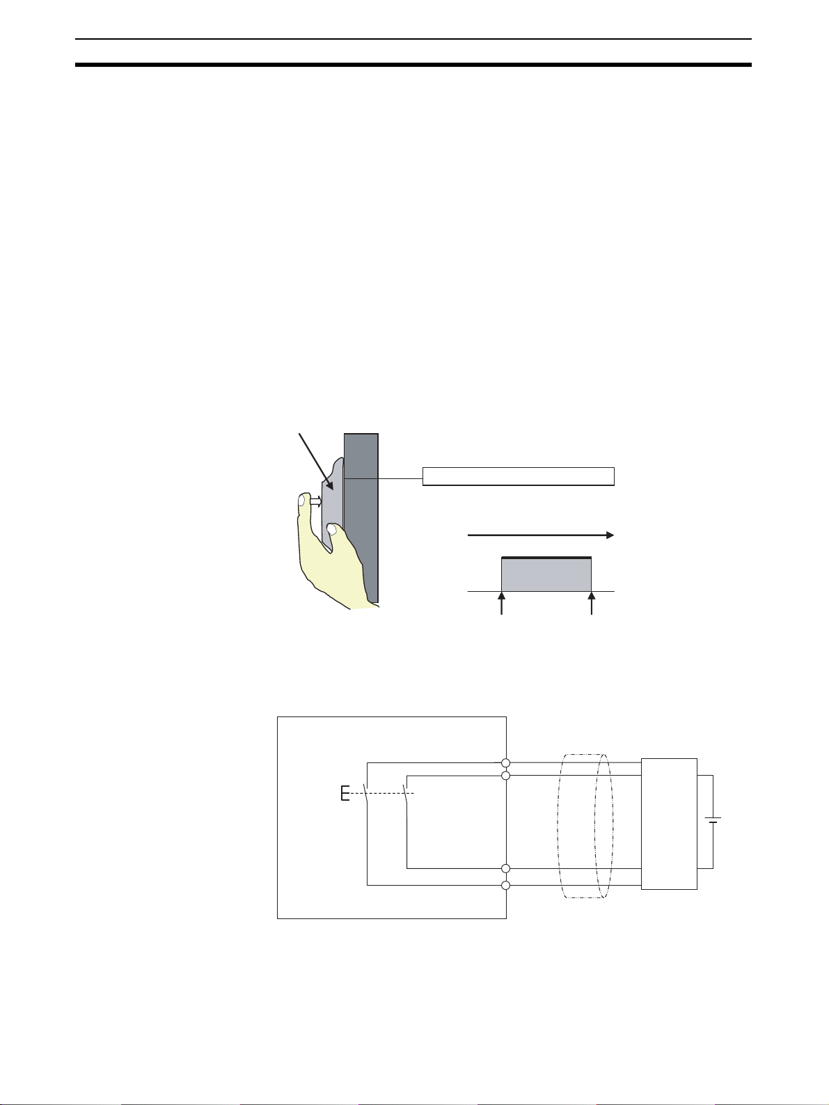
Enabling Switch Section 3-3
3-3 Enabling Switch
3-3-1 Overview
In contrast to the emergency stop switch, which lets a worker intentionally
stop the machine in case of an emergency, the enabling switch makes it easier to avoid danger with no conscious decision by a worker. When work is
required in hazardous areas, e.g, during maintenance, devices with enabling
switches provide an important safety measure by preventing unexpected
operations from occurring while work is underway in the those areas.
Manual operation of devices is permitted while the enabling switch is lightly
pressed. At soon as a hazardous situation arises, however, operation is
stopped if the worker instinctively either lets go of the enabling switch or
grasps it more tightly.
Some standards, such as the ANSI/RIA R15.06 and CSA/Z434-03 Industrial
Robot Standards and the ANSI/B11.19 Machine Tool Standards, require the
use of enabling switches. In EN 60204-1, enabling switches are not required
but are recommended as auxiliary devices.
External Connection
Diagram
Enabling switch
Hard-wired DPST-NO contact (3-position)
Pressure
ON
OFF
Ordinary pressure:
Turns ON
Pressed in:
Turns OFF
The status of the enabling switch’s DPST-NO contact is output externally
using a hard-wired output from the Special Cable.
Enabling switch
DPST-NO
NSH5
ENB1 ENB2
ENB1A1
ENB2A1
Special Cable
Safety
circuit
36
ENB2A2
ENB1A2
Page 58

Function Switches Section 3-4
3-4 Function Switches
3-4-1 Overview
The NSH5 has ten function switches, and the status of these switches can be
sent to hard-wired outputs or to internal memory or host (PLC) memory.
F6
F7
F1
F2
Hard-wired outputs
External Connection
Diagram
F8
F9
F3
F4
F5 F10
Software NO conditions
The status of function switches F1, F2, F6, and F7 is output externally by
hard-wired outputs via the Special Cable. The status of the six remaining
switches (F3, F4, F5, F8, F9, and F10) are output to internal memory or host
(PLC) memory.
The status of function switches F1, F2, F6, and F7 are output externally by
hard-wired outputs via the Special Cable.
Function switches
Four NO contacts output to external devices
NSH5
Special Cable
F1
F2
F6
F7
F6
F2
F1
F7
SW COM
PLC
PLC
PLC PLC
Internal Memory or Host
(PLC) Memory Allocation
NSH5 function switches F3 to F5 and F8 to F10 can be allocated any bit
addresses in the internal memory or host (PLC) memory, and their ON/OFF
status can be monitored at the allocated address.
To specify the address in internal memory or host (PLC) memory that is to be
allocated to a function switch, first select PT - System Setting in CX-Designer
and then click the NS Handy Terminal Tab. In the Key Status Monitor
Address Field, click the appropriate Set Button, and specify the address that
is to be allocated.
37
Page 59

Memory Cards Section 3-5
Allocate addresses in internal
memory or host memory to
function switches F3 to F5 and
F8 to F10.
The following points apply to the function switch allocations.
• Only bit addresses can be set.
• Addresses can be set in either internal memory or host memory.
• System memory $SB cannot be allocated.
• No address is allocated for the default setting.
The NS Handy Terminal Tab can be selected only when the PT model is set
to the NSH5. It cannot be selected for any other PT model.
3-5 Memory Cards
Memory Cards are used for storing and transferring screen data, log data,
and system programs. This section provides an overview of Memory Card
functions. Refer to the NS-Designer Operation Manual (Cat. No. V074-E1) for
details on Support Software transferring methods.
3-5-1 Memory Card Applications
Memory Cards can be used at the PT itself. Log files can be saved to a Memory Card as CSV files. There are four kinds of log files, as shown in the following table.
Alarm/event
history
Data log Stores trend data.
Operation log Stores screen operation log data.
Error log Stores error log data for when macros are executed.
Log data is normally saved in internal memory that is backed up in the PT, but
can also be saved in CSV file format. When log data is saved as a CSV file, it
is stored on the Memory Card. The CSV files containing log data are saved in
the log folder created in the Memory Card.
The following data can be transferred using a Memory Card.
• System programs (programs required for operating the PT, such as for
communications and fonts)
Stores alarm/event history data that has been registered by CXDesigner.
38
Page 60

Memory Cards Section 3-5
• Screen data (data used in the PT display)
The transfer method is manual transfer (i.e., the data to be transferred
and the transfer direction are selected manually), and operations are
specified from the System Menu.
Note There are four recommended Memory Card models, each of which, has a dif-
ferent capacity.
Model Capacity Memory type
HMC-EF183 128 MB Flash memory
HMC-EF283 256 MB Flash memory
HMC-EF583 512 MB Flash memory
A Memory Card can be overwritten approximately 100,000 times. When using
a PC card socket in devices such as notebook computers, use an HMCAP001 Memory Card Adapter.
Note Use the Memory Cards recommended by OMRON. Operation may not be cor-
rect if other memory cards are used.
3-5-2 Mounting and Removing Memory Cards
Mounting a Memory Card
1,2,3... 1. As shown below, to mount the Memory Card to the Memory Card interface
first loosen the two screws securing the cover on the top of the PT.
39
Page 61

Memory Cards Section 3-5
2. After the screws have been removed, open the cover by pulling it up and
forward with a finger.
3. Insert the Memory Card all the way in. (As this is done, the eject button will
pop out.)
Note Tighten the cover to a force of 0.9 N.
Removing a Memory Card Press the eject button to remove the Memory Card. To prevent the Memory
Card from popping out and falling, hold the Memory Card with your index finger while pushing the eject button with your middle finger.
3-5-3 Replacing the System Program
The system program in the PT can be replaced or upgraded to a higher version. There are two methods that can be used to replace the system program.
• Using a recovery/upgrade program
• Transferring system program data
Note (1) The system program must be version 8.0 or higher to be installed.
(2) Consult your OMRON representative if a system program of a version
lower than 8.0 is to be installed.
(3) Use the recovery/update program to install the system program.
Using a Recovery/
Upgrade Program
Use the following procedure to replace the system program if the system program becomes corrupted and the PT will not start or to upgrade the system
program in the PT.
40
Page 62

Memory Cards Section 3-5
1,2,3... 1. Copy all of the files and folders in the RecoverUpdate_@_@ folder inside
the CX-Designer installation folder (default: C:\ProgramFiles\Omron\CXOne\CX-Designer) to a Memory Card. This program can be selected when
installing the CX-Designer.
(“@_@” will be replaced by numbers indicating the system program version. For example “RecoverUpdate_7_0” is the file for version 7.0.)
2. Insert the Memory Card into the PT and turn ON the power supply. The recovery/update program will start automatically.
3. The indicator will flash green when the download has been completed normally.
Note (1) For details on the recovery/update program, select Start - Program -
OMRON - CX-One - CX-Designer - How to recover the system prog
Ver. 7.0.
(2) Refer to information on the procedure for recovery and update and to the
Setup Manual for troubleshooting information if an error is displayed
when you use the recovery/update program.
Transferring System
Program Data
The System Program is stored under the CX-Designer's install folder (default
location is C:\Program Files\Omron\CX-One\CX-Designer) in folders that are
created for each type and version, as follows:
\SystemBackup\NSH5\V@_@\bank1: NSH5 system program
(“@_@” will be replaced by numbers indicating the system program version.
For example “RecoverUpdate_7_0” is the file for version 7.0.)
To replace a system program, use Windows Explorer or another method to
copy each of the folders for the required system program under \bank1 to the
route directory of the Memory Card.
For details on methods for transferring data from the Memory Card to the PT,
refer to 3-5-4 Transferring Data with Memory Cards.
The system backup folder can be created only if CX-Designer is installed from
the stand-alone CD-ROM. If the CX-Designer is installed from CX-One, reinstall the system program by following the procedure for using a recovery/
update program described above.
3-5-4 Transferring Data with Memory Cards
Using a Memory Card with the PT allows system programs (programs
required for operating the PT, such as programs for communications and
fonts) and screen data to be transferred to and from the PT.
There are several types of data transfers, including manual transfers (in which
the data to be transferred and the direction of transfer are selected manually),
downloads (in which data is transferred automatically from the Memory Card
to the PT), uploads (in which data is transferred automatically from the PT to
the Memory Card), and bank specifications (four banks max.). The transfer
method is specified using the System Menu.
Note (1) Before transferring data, check to be sure that the system programs and
screen data types match those in the PT.
(2) Do not perform the following operations while accessing the Memory
Card. The data may be damaged and the Memory Card may need to be
formatted.
• Turning OFF the power to the PT.
• Removing the Memory Card.
41
Page 63

Memory Cards Section 3-5
Always follow the correct procedure for removing a Memory Card.
If the PT system has been damaged due to the power being turned OFF while
a file is being written, it may not be possible to use normal downloading to
replace a system program. If this situation occurs, refer to Troubleshooting
below.
Manual Transfer Use screen operations to select the transfer direction (download, upload),
contents (project, project & system program, or system program), and banks.
Use the following procedure to manually transfer data.
1,2,3... 1. Turn ON the power to the PT.
2. Insert the Memory Card into the PT.
3. Simultaneously press two of the four corners of the PT touch panel to display the System Menu Screen.
4. Display the Special Screen Tab Page under system settings, and execute
Memory Card transfer on page 2-2 of the screen.
5. Select the display language. The following screen will be displayed at the
PT if English is the language selected.
6. Specify the transfer direction (download, upload), contents (project, project
& system program, or system program), and bank. The IPP file name and
system version that are stored in both the specified bank of the Memory
Card and the PT will be displayed in the Project File and System Version
fields.
7. Check the contents, and the press the Go! Button. A message asking for
confirmation of the transfer will be displayed.
8. Press the Yes Button to execute the specified data transfer operation.
When data is downloaded, the screen data previously stored in the PT will
be deleted.
9. A warning message will be displayed if the PT model, system program,
screen data version, or language for the language stored in the PT are different from that for the data stored in the Memory Card. Press the Ye s Button to continue the data transfer.
10. While the data is being transferred, an uploading or downloading screen
will be displayed. A screen indicating that the transfer has been completed
will be displayed when the data transfer is finished. (If an error occurs, a
transfer error screen will be displayed. If that occurs, refer to Troubleshoot-
ing below.)
11. The indicator will flash green when the data transfer has been completed.
At this point the Memory Card can be removed.
12. Press the Reset Button to reset the PT.
If the wrong data is downloaded, execute the transfer operation again.
42
Page 64

Memory Cards Section 3-5
The system settings (set in the System Setting using the CX-Designer) are
not changed for the upload operation.
Troubleshooting If an error occurs while data is being transferred, a transfer error screen will be
displayed. Check the following items for the messages that are displayed.
Error message Items to check
Memory Card Error
Could not recognize the Memory
Card. Check the Memory Card
and reset the PT.
Project Transmission Error
Transmission failed. Check the
Memory Card and reset the PT.
System Transmission Error
Transmission failed. Check the
Memory Card and reset the PT.
Project Transmission Error
The project cannot be transferred
because it does not match.
System Transmission Error
The system cannot be transferred
because the hardware does not
match.
Cannot find source data. Continue
downloading/uploading?
Is a Memory Card inserted into the PT?
Is the Memory Card damaged?
Was the Memory Card removed during data
transfer?
Is there insufficient free space on the Memory
Card?
Is the Memory Card damaged?
Does the screen volume exceed the memory
capacity of the PT?
Do the NS-series, NSH5-series, and NSJ-series
projects, systems, and PT models match for the
transmission source and destination?
Does the transfer source directory or file exist?
(Note: If the Yes Button is pressed and data is
transferred, the previous data at the transfer destination will be deleted.)
After checking the message, reset the PT and transfer the data again. If the
PT system has been damaged due to the power being turned OFF while a file
is being written, it may not be possible to use normal downloading to replace a
system program.
If the system program cannot be replaced or has been corrupted, and the PT
will not start, refer to 3-5-3 Replacing the System Program and replace the
system program using the information provided there.
43
Page 65

USB Port Section 3-6
3-6 USB Port
The USB port can be used to transfer screens created by the CX-Designer.
For details, refer to the NS Series Setup Manual (Cat. No. V083-E1).
3-6-1 Connecting to the USB Port
Open the cover on top of the PT, as shown in the following diagram, and connect a commercially available USB cable to the USB port. (For details on
opening the cover, refer to 3-5 Memory Cards.)
3-7 Usable Host Connection Methods
The NSH5 has one serial port corresponding to serial port A in the NS Series,
for connecting to the PLC. Unlike with the NS Series, it is not possible to connect using serial port B, the Ethernet port, or Controller Link. When using CXDesigner to set the connection method, do not set any communications ports
other than serial port A.
The communications methods shown in the following table can be set, using
the serial port.
Host connection method Usability
1:N NT Link OK (See note 1.)
1:1 NT Link OK
Host Link OK
Note (1) Only one NSH5 can be connected to any one communications port on the
PLC. More than one PT cannot be connected at the same time.
(2) Only PT memory can be allocated as the notification destination for the
emergency stop switch and function switches F3 to F5 and F8 to F10.
Host allocations are not possible.
The PT can also communicate with the following products:
• Mitsubishi FX-series, A-series, and Q-series PLCs
• SIEMENS S7-300-series PLCs
• Yaskawa MP-series Machine Controllers
• Yaskawa Varispeed F7-series and VS mini V7-series Inverters
• Rockwell Automation (Allen-Bradley) SLC500, MicroLogix, PLC-5, CompactLogix, and ControlLogix Controllers
• Products supporting Modbus RTU
(Host Link OK with restrictions) (See note 2.)
44
Page 66

Station Detection Function Section 3-8
Refer to the Host Connection Manual (Multivendor Connection) for connection
methods.
3-8 Station Detection Function
The station detection function allows the NSH5 to read the box number
switches (4-bit switches) for removable boxes. Thus, when a removable box is
connected, the NSH5 is able to detect it.
By automatically displaying station screens, and by giving notification of which
station the PLC is currently in, the stations that can be operated can be limited. To ensure safety, other forms of operation are disabled.
Internal Memory
Allocation
The PT’s station detection function can be allocated any address in the internal memory, and the ON/OFF status can be monitored at the allocated
address.
To specify the address in internal memory that is to be allocated for the station
status monitor address, first select PT - System Setting in CX-Designer version 6.5 or higher, and then click the NS Handy Terminal Tab. In the Station
Status Monitor Address Field, click the appropriate Set Button, and specify
the address that is to be allocated.
When removable boxes are used, the station numbers for the removable
boxes are acquired and notification is provided to one word in either $W or
$HW in PT memory. If function key status cannot be obtained due to a problem, such as a hardware error, or when a status error flag for an error, such as
a communications error, is generated, notification is provided to the same
word.
Bit allocations within the word is as follows:
Bit Name Status
Bit 15 Board Error Bit ON: Error
Bit 14 Host Communications Error Bit
Bit 13 Reserved --Bit 12 Reserved --Bit 11 Reserved --Bit 10 Reserved --Bit 9 Reserved --Bit 8 Reserved --Bit 7 Reserved --Bit 6 Reserved --Bit 5 Reserved --Bit 4 Reserved --Bit 3 S4 (Station ID line 4 signal status) 0: Not connected
Bit 2 S3 (Station ID line 3 signal status)
Bit 1 S2 (Station ID line 2 signal status)
Bit 0 S1 (Station ID line 1 signal status)
OFF: Normal
1 to 15 (binary format):
Station number
Any number from 1 to 15 can be set for a station box. For station number
switches, wire station ID line signals S1 to S4 in relation to the station numbers as shown in the following table.
Not
connected
S4 0 000000011111111
S3 0 000111100001111
123456789101112131415
Station number
45
Page 67

Station Detection Function Section 3-8
Not
connected
S2 0 011001100110011
S1 0 101010101010101
123456789101112131415
Station number
1: Signal level ON, 0: Signal level OFF
Internal memory allocation for
station detection function
The following points apply to the allocation for the station detection function.
• Only word addresses can be set.
• Addresses can be set in either internal memory only.
• System memory $SW cannot be allocated.
• No word address is allocated in the default setting.
The NS Handy Terminal Tab can be selected only when the PT model is set
to the NSH5. It cannot be selected for any other PT model.
46
Page 68

Connecting to the Removable Box
This chapter describes the Removable Box, which is connected to the NSH5.
4-1 Overview of Removable Box . . . . . . . . . . . . . . . . . . . . . . . . . . . . . . . . . . . . . 48
4-2 Nomenclature and Functions . . . . . . . . . . . . . . . . . . . . . . . . . . . . . . . . . . . . . 48
4-3 Switch Settings . . . . . . . . . . . . . . . . . . . . . . . . . . . . . . . . . . . . . . . . . . . . . . . . 52
4-4 Installation. . . . . . . . . . . . . . . . . . . . . . . . . . . . . . . . . . . . . . . . . . . . . . . . . . . . 53
4-5 Connection Method. . . . . . . . . . . . . . . . . . . . . . . . . . . . . . . . . . . . . . . . . . . . . 55
SECTION 4
47
Page 69

Overview of Removable Box Section 4-1
4-1 Overview of Removable Box
An NSH5-AL001 Removable Box can be connected between the NSH5SQG@0B-V2 PT (the model with a gray stop switch) and the host PLC to
enable easily attaching and detaching the NSH5 without affecting the wiring to
the PLC or safety circuits. The Removable Box also enables converting
between RS-232C and RS-422A.
The Removable Box is equipped with a rotary switch to set the station number
used to identify the Removable Box and a DIP switch for setting RS-422A
communications conditions.
System Configuration The NSH5 PT is connected to a PLC through the Removable Box. Always use
an NSH5-232CN-3M/10M Special Cable to connect the NSH5 PT to the
Removable Box.
NSH5-SQG@0B-V2
RUN
F6
F7
F8
F9
F10
R
E
S
E
T
T
E
S
E
R
R
E
S
E
T
F1
F2
F3
F4
F5
Removable Box
NSH5-AL001
External Switch
Output
Safety circuit
CS/CJ-series PLC
RS-232C
Connected via NSH5-232CN-3M/10M Special Cable.
Note (1) Always turn OFF the key switch before connecting or disconnecting the
Cable using the Removable Box.
(2) Always use the Removable Box connected to the NSH5-SQG@0B-V2 PT
(the model with a gray emergency switch).
4-2 Nomenclature and Functions
This section describes names and function of the components of the Removable Box.
Hard-wired Terminal Block
Connects hard-wired output signals.
Key Switch
Used to turn the power ON and OFF.
RS-232C Connector
Connected to the Special Cable
(NSH5-232CN-3M/10M)
RS-422A
DIP Switch
Used to set RS-422A communications conditions.
Rotary Switch
Used to set the station number.
RS-422A Terminal Block
Connects to RS-422A cable.
48
Hooks
Used to mount the Removable Box to DIN Track.
Terminal block and connector pin arrangement details are shown below.
Page 70

Nomenclature and Functions Section 4-2
RS-422A Connector
Pin No. Signal Contents
1 RDB+ Receive Data B
2RDA− Receive Data a
3 SDB+ Send Data B
4SDA− Send Data A
5RSA− Request Send A
6 RSB+ Request Send B
7SG0 V
8 FG Frame ground
Pin No. Signal Contents
1 S1 Station ID line 1
2 S2 Station ID line 2
3 0 V (SG) Station ID line 0 V
4 CONECT1 Cable Connection Confirmation Line
5 NC Not connected
6 RD Receive Data
7 SD Send Data
8 NC Not connected
9 SWCOM Function switch common
10 F6 Function switch F6
11 F1 Function switch F1
12 NC Not connected
13 ENB1A1 Enabling switch line 1
14 ENB2A1 Enabling switch line 2
15 EMG1A1 Stop switch line 1
16 EMG2A1 Stop switch line 2
17 NC Not connected
18 0 V 0-V Power Supply Input
19 24 V +24-V Power Supply Input
20 S3 Station ID line 3
21 S4 Station ID line 4
22 CONECT2 Cable Connection Confirmation Line
23 NC Not connected
24 0 V (SG) Secondary Ground
25 RS Request Send
26 CS Clear to Send
27 NC Not connected
28 NC Not connected
29 F7 Function switch F7
30 F2 Function switch F2
31 NC Not connected
32 ENB1A2 Enabling switch line 1
33 ENB2A2 Enabling switch line 2
34 EMG1A2 Stop switch line 1
35 EMG2A2 Stop switch line 2
36 NC Not connected
37 FG Frame ground
RS-232C Connector
1
1
2
2
3
3
4
4
5
5
6
6
7
7
8
8
1
1
2
2
3
3
4
4
5
5
6
6
7
7
8
8
9
9
10
10
11
11
12
12
13
13
14
14
15
15
16
16
17
17
18
18
19
19
20
20
21
21
22
22
23
23
24
24
25
25
26
26
27
27
28
28
29
29
30
30
31
31
32
32
33
33
34
34
35
35
36
36
37
37
49
Page 71

Nomenclature and Functions Section 4-2
Hard-wired Terminal Block Be sure the wires connected to the hard-wired output terminals have a total
length of no more than 3 meters.
Pin No. Signal Contents
1 NC Not connected
2 NC Not connected
3 CONECT1 Cable Connection Confirmation Line
1
11
11
13
13
15
15
17
17
19
19
21
21
1
3
3
5
5
7
7
9
9
4 CONECT2 Cable Connection Confirmation Line
2
2
5 F1 Function switch F1
4
4
6 F2 Function switch F2
7 F6 Function switch F6
6
6
8 F7 Function switch F7
8
8
9 SWCOM Function switch common
10
10
10 ENB1A1 Enabling switch line 1
11 ENB1A2 Enabling switch line 1
12
12
12 ENB2A1 Enabling switch line 2
14
14
13 ENB2A2 Enabling switch line 2
14 EMG1A1 Stop switch line 1
16
16
15 EMG1A2 Stop switch line 1
18
18
16 EMG2A1 Stop switch line 2
20
20
17 EMG2A2 Stop switch line 2
18 ENB-CH1 Key Switch Confirmation Signal Line
22
22
19 ENB-CH2 Key Switch Confirmation Signal Line
20 24 V +24-V power supply input
21 0 V 0-V power supply input
22 FG Frame ground
CONECT1/2: These signal lines are used to confirm that the NSH5 Cable is
connected to the Removable Box. Attaching the connector will
short the CONECT1 and CONECT2 pins. When using a PLC
I/O Unit, use these signal lines to confirm the connection.
ENB-CH1/2: These signal lines are used to confirm the key switch condition
when using the NSH5 in Teaching Mode. If the key switch is
turned ON, the internal relay is turned ON, which will short the
ENB-CH1 and ENB-CH2 pins. (The key ON/OFF position can
be checked using external contacts.) Use these signal lines
when using the enabling switch as described in Appendix E
Recommended Enabling Circuits.
24 VDC/0 VDC: Power to the NSH5 is supplied from the NSH5-AL001.
EMG1A1/EMG1A2
EMG2A1/EMG2A2
When the power is OFF, the internal relay (NC) is turned ON, placing the stop
switch line in loopback status.
When the power is ON, the internal relay (NC) is turned OFF, and the stop
switch line is connected to the NSH5.
50
Page 72

Nomenclature and Functions Section 4-2
2
RS-232C connector
RD
SD
RS
CS
0 V (SG)
24 V
0 V
FG
S1
S2
S3
S4
0 V (SG)
CONECT1
CONECT2
Isolation from
24 VDC to 5 VDC
1
2
3
4
Rotary switch
Isolation between
RS-232 and RS-422A
+
Relay
−
Terminating
resistance switch
Key switch
(NO)
Relay (NO)
RS-422A connector
Hard-wired terminal
block
Fuse
SDA−
SDB+
RDA−
RDA+
RSA−
RSA+
SG
FG
24 V
0 V
FG
ENB-CH1
ENB-CH2
CONECT1
CONECT
EMG1A1
EMG1A1
Relay (NC)
EMG1A2
EMG2A1
EMG2A2
ENB1A1
ENB1A2
ENB2A1
ENB2A2
F1
F2
F6
F7
SWCOM
Relay (NC)
EMG1A2
EMG2A1
EMG2A2
ENB1A1
ENB1A2
ENB2A1
ENB2A2
F1
F2
F6
F7
SWCOM
Note CONNECT1 and CONNECT 2 are shorted in the NSH5 Cable (NSH5-232CN-
3M/10M).
51
Page 73

Switch Settings Section 4-3
4-3 Switch Settings
Key Switch Power to the Removable Box is turned ON and OFF with the key switch.
The power is OFF when the key is in the vertical position. (Refer to the
diagram below.)
The key can be removed when the power is turned OFF.
OFF
ON
OFF
ON
Note Always turn OFF the key switch before connecting or disconnecting the Cable
using the Removable Box.
DIP Switch The DIP switch is used to set RS-422A communications conditions. Set the
DIP switch before connecting the cable to the Removable Box.
ON
ON
ON
ON
234
1
1
OFF
OFF
Pin No. Description ON OFF
1 Built-in terminating
2, 3 Do not change these
4 RS-422A transmission
4
Factory setting: SW1 is ON
resistance setting
settings.
mode setting
Terminating resistance
is connected.
--- ---
RS-232C CS control Always send
Terminating resistance
is not connected.
52
Note When using a single NSH5 PT, turn OFF pin 4 (always send). When using
more than one NSH5 PT, turn ON pin 4 (RS-232C CS control).
In station detection mode, use the rotary switch to set a station number
between 1 and 15 for the Removable Box. Set this switch before connecting
any cables to the Removable Box. (Station number 0 means that the Removable Box is not connected.) For details on the station detection function, refer
to 3-8 Station Detection Function.
0
0
1
1
F
F
2
2
E
E
D
D
C
C
B
B
Station number 0123456789101112131415
Rotary switch 0123456789AbCDEF
3
3
4
4
5
5
6
6
A
A
7
7
8
8
9
9
Factory setting
Note Always turn OFF the Removable Box's key switch before setting the DIP
switch or the rotary switch.
Page 74

Installation Section 4-4
4-4 Installation
Dimensions
39.5
120
(143.5)
65.5
23 92.5
6
66.5
23.5
15.95
44.8
23.6
41.5
6.1
20.05
42.5
86
94
100
50
The Removable Box can be installed using any of the following three methods.
Mounting to a Panel To mount the Removable Box on a panel, use the mounting brackets and tool
(Phillips screwdriver) that are included in the package.
Note (1) Do not allow metal particles to enter the Removable Box while work is be-
ing done on the panel.
(2) The mounting panel must be between 1.6 and 4.8 mm thick.
(3) Secure the mounting brackets with a uniform tightening torque of 0.5 to
0.6 N·m. Use a panel that is clean, undistorted, and strong enough to ad-
equately support the Removable Box.
(4) Do not use the Removable Box in environments that require water resis-
tance or oil resistance.
1. Refer to the cutout dimensions in the following diagram and cut out a hole
for embedding the Removable Box, Then insert the Removable Box from
the front side of the panel.
60.5
+0.
+0.5
61.5
61.5
0
+0.5
95
95
0
53
Page 75
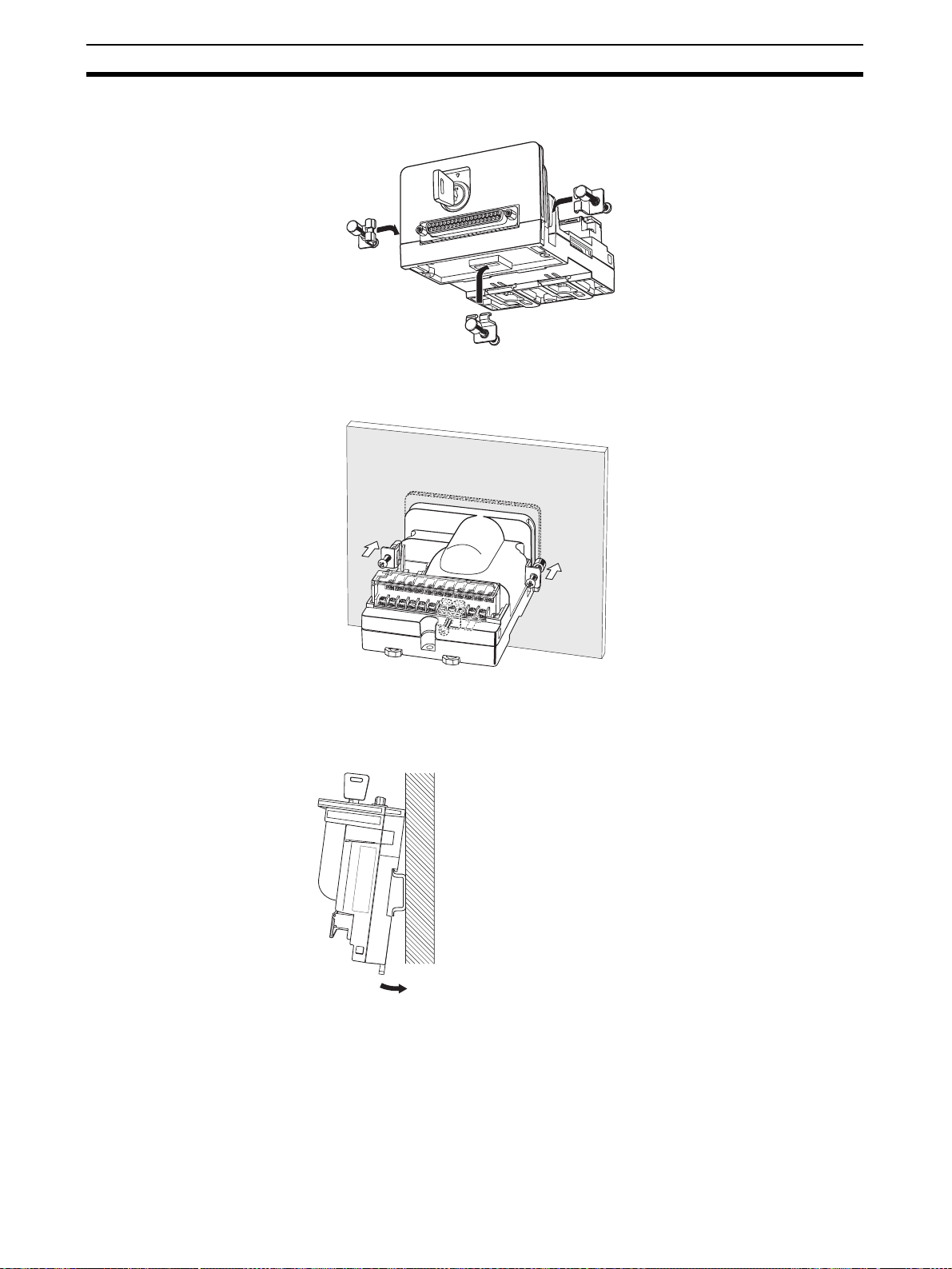
Installation Section 4-4
2. As shown in the following diagram, attach the mounting brackets to the Removable Box mounting holes or slots (3 places).
3. From the back of the panel, hold the Removable Box to pull the mounting
brackets toward you and tighten the mounting bracket screws to secure the
Removable Box.
Mounting to a DIN Track Catch the upper hook on the back of the Removable Box on the DIN Track,
and push in the direction of the arrow and secure the Removable Box with the
bottom latch. Attach End Plates to the right and left of the Removable Box so
that it does not shift in either direction.
Note When mounting the Removable Box on a DIN Track, be sure to secure the
cable so that no load is placed on the connector. The Removable Box or DIN
Track may be damaged if the cable places a load on the connector.
54
Page 76

Connection Method Section 4-5
Removing from a DIN
Track
Remove the End Plates, and then insert a screwdriver in the hooks on the
base of the Removable Box and pull down.
Mounting to a Panel Referring to the dimensions in the following diagram, cut three holes in a
panel with a minimum thickness of 2 mm. Secure the Removable Box to the
panel with screws using the screw (4M × 14) mounting holes on the Removable Box.
92.5±0.3
3-M
Mounting holes.
Note To ensure that the Removable Box is mounted securely, use a panel with a
thickness of at least 2 mm.
4-5 Connection Method
The Removable Box is connected between the NSH5 PT and a PLC.
Precautions Prior to
Wiring
Check the following items prior to wiring.
• Signal Lines
Make sure that the PLC's I/O are correct.
• NSH5 Special Cable Connector
Make sure that the NSH5 Special Cable connector screws and the
Removable Box are securely locked.
• Hard-wired Terminal Block
The hard-wired terminal block is removable. Make sure it is securely connected and that all screws are tight.
• RS-422A Terminal Block
Make sure that all I/O lines between the PLC and the Removable Box are
correct.
• NSH5 Unit Number Setting
When using more than one NSH5 PT, make sure in advance that no unit
numbers are used more than once. If duplicate numbers exist, a communications error will occur.
86±0.3
Recommended mounting dimensions
55
Page 77

Connection Method Section 4-5
RS-422A Wiring
RS-422A Terminal Block on
Removable Box
Name
Functional ground
SDB
RS-422A
Connector
SDA
RDB
RDA
Pin No.
8
3
4
1
2
(See note 1.)
(See
note 2.)
PLC
Pin No.
Name
Shield ground terminal
SD+
SD−
RD+
RD−
RS-422A
Connector
(8-pin terminal block)
Use twisted-pair wires for SDB and SDA, and for RDB and RDA.
Shield
Note (1) Ground the shield only to the host (PLC) to prevent malfunctions due to
ground potential differences.
(2) Recommended cables: TKVVBS4P-03 (100 m Tachii Electric Wire) or
AWG22 shielded cable.
Ground and Shield Wiring Perform the following connections, shield wiring, and grounding in any com-
munications system using the Removable Box. Incorrect connections may
cause a host communications error.
• Connecting the Removable Box D-Sub Connector
Be sure to fasten the screws on both sides of the D-Sub connector. If
these screws are not fastened, the NSH5 PT's functional ground terminal
and the Removable Box's FG will not be connected.
• Ground Line Wiring
The Removable Box is equipped with a functional ground ( ).
1. Normally, ground the Removable Box as shown in Figure A on the fol-
lowing page.
• Connect the ground terminals on all Units and the functional ground,
and ground the line at one location to 100
Ω or less.
• Short the PLC's LG terminal and the GR terminal.
• The ground wire must be 2 mm
2
or larger.
• For detailed grounding instructions, refer to the operation manual for
the Communications Unit.
2. If a source of noise, such as a motor or inverter, is grounded to the same
panel, do not ground the Removable Box's functional ground terminal
( ), as shown in the Figure B.
• RS-422A Cable Shield Wiring
Be sure to connect the shield on the RS-422A cable. If the shield is not
connected, a host communications error may occur.
When connecting the ground terminals on all Units and the functional
ground, and grounding the line at one location to 100
Ω or less, connect
the shield only at one end of each line, as shown in Figure A.
If the Removable Box's functional ground terminal is not grounded, connect the shield at both ends of each line, as shown in Figure B.
If a CJ1W-CIF11 is also connected in the system, connect the lines and
shield as shown in Figure B.
56
Page 78

Connection Method Section 4-5
Figure A
CPU Rack
Power
CPU
Supply
or
Unit
Com Unit
LG
RG
CPU Rack
Figure B
CPU
or
Com Unit
Power
Supply
Unit
RG
LG
NSH5-AL001
Terminal block
FG
RS422A
FG
Terminal block
FG
RS422A
FG
NSH5-AL001
Terminal block
FG
RS422A
FG
RS422A
NSH5-AL001
NSH5-AL001
Terminal block
FG
FG
NSH5-232CN-3M, 10M
NSH5-232CN-3M, 10M
NSH5-232CN-3M, 10M
NSH5-232CN-3M, 10M
NSH
PT
NSH
PT
NSH
PT
NSH
PT
NSH5-AL001
Terminal block
FG
RS422A
FG
NSH5-AL001
Terminal block
FG
RS422A
FG
NSH5-232CN-3M, 10M
NSH5-232CN-3M, 10M
NSH
PT
NSH
PT
57
Page 79

Connection Method Section 4-5
Connection Formats • Connection via a NSH5-AL001 Removable Box
NSH5-SQG@0B-V2
R
E
S
E
T
T
E
S
E
R
R
E
S
E
RUN
F6
F7
F8
F9
F10
T
F1
F2
F3
F4
F5
NSH5-AL001
CS/CJ-series PLC
RS-232C
RS-422A
Special Cable (NSH5-232CN-3M/10M)
• 1:N Connections via NSH5-AL001 Removable Box
The total communications distance can be up to a 500 m.
NSH5-SQG@0B-V2
RUN
F6
F7
F8
F9
F10
RS-232C
NSH5-AL001
NSH5-SQG@0B-V2 NSH5-SQG@0B-V2
R
E
S
E
T
T
E
S
E
R
R
E
S
E
T
RUN
F1
F6
F2
F7
F3
F8
F4
F9
F5
F10
R
E
S
E
T
T
E
S
E
R
R
E
S
E
T
F1
F2
F3
F4
F5
RS-232C
NSH5-AL001
RS-422A
RUN
F6
F7
F8
F9
F10
RS-232C
R
E
S
E
T
T
E
S
E
R
R
E
S
E
T
F1
F2
F3
F4
F5
NSH5-AL001
CS/C-series PLC
58
Page 80

Connection Method Section 4-5
• 1:N Connections Including a Conversion Unit Other Than the NSH5AL001
NSH5-SQG@0B-V2
R
E
S
E
T
T
E
S
E
R
R
E
S
E
RUN
F6
F7
F8
F9
F10
RS-232C
T
F1
F2
F3
F4
F5
NSH5-AL001
CS/CJ-series PLC
NT-AL001
RS-422A
RS-232C
Note (1) When the CJ1W-CIF11 is included in the connections, the maximum
communications distance is 50 m. When the CJ1W-CIF11 is not included
in the connections, the maximum communications distance is 500 m.
(2) If ground potential differences or noise is a concern, the insulated NT-
AL001 RS-232C/422A Conversion Unit is recommended for all connections.
59
Page 81

Connection Method Section 4-5
60
Page 82

SECTION 5
Inspection and Maintenance
This section describes inspection and maintenance and the contents of error messages for the NSH5 Programmable
Termi nal.
5-1 Maintenance . . . . . . . . . . . . . . . . . . . . . . . . . . . . . . . . . . . . . . . . . . . . . . . . . . 62
5-2 Inspection and Cleaning . . . . . . . . . . . . . . . . . . . . . . . . . . . . . . . . . . . . . . . . . 63
5-3 Error Message Tables . . . . . . . . . . . . . . . . . . . . . . . . . . . . . . . . . . . . . . . . . . . 65
5-4 Precautions When Replacing the PT. . . . . . . . . . . . . . . . . . . . . . . . . . . . . . . . 65
61
Page 83

Maintenance Section 5-1
5-1 Maintenance
Perform maintenance operations to keep the NSH5-series PT in optimum
condition.
!WARNING Do not disassemble the PT or touch the inside of the PT while the power is
turned ON. Doing so may result in electrical shock.
Backing Up Project Data Be sure to back up project data and store it in a secure location, in case the
PT should have to be sent out for repairs or be replaced.
Keeping a Spare PT It is recommended that a spare PT be kept on hand, in order to enable faster
system recovery in case the original PT should be damaged or the screen
cannot be read due to reaching the end of the backlight service.
Replacing the Backlight If the brightness of the backlight is diminished and the screen becomes diffi-
cult to read, the backlight must be replaced. A backlight cannot be replaced by
the user. If this situation occurs, please contact an OMRON representative.
Ordinarily a backlight would need to be replaced after approximately 75,000
hours at normal temperature and humidity. The service life is shortened in an
extremely cold environment. Replace the backlight if the brightness diminishes and the screen becomes difficult to read.
Replacing the Battery Screen data such as calendars, clocks, and log data are backed up by a lith-
ium battery. The battery service life is approximately five years when used in
an environment with a temperature of 25
of use is higher than this, the battery life will be shortened. Change the battery
at suitable intervals in accordance with the operating environment.
It is recommended that a spare battery be kept on hand so that the battery
can be quickly replaced when necessary.
Replacement Battery
The replacement battery shown below is a lithium battery for backing up the
memory contents.
Model Specifications
CJ1W-BAT01 Replacement battery for the NSH5
Replacement Criteria
Replace the battery under the following conditions.
• When five years have elapsed since a new battery was last installed
• Within five days of when the RUN indicator turns orange
Note (1) Never use a battery that has been subjected to any strong impact, such
as being dropped on the floor, as the battery may lead fluid.
(2) Before installing a battery, check the battery type and be sure to install it
correctly.
°C. If the temperature at the location
62
Page 84

Inspection and Cleaning Section 5-2
Replacement Procedure
Use the following procedure to replace the battery.
1,2,3... 1. Remove the back cover from the PT. The battery is located as shown in the
diagram below. (For details on removing the back cover, refer to 2-3 Con-
necting the Special Cable.)
2. To replace the battery, remove the connector as shown below.
1
O
N
2
3
4
Note Replace the battery within five minutes of disconnecting it.
5-2 Inspection and Cleaning
Clean and inspect the NSH5-series PT regularly to ensure that it is always
used under optimum conditions.
Cleaning If the display gets dirty, the screen becomes difficult to read. Clean the screen
periodically as follows:
• Wipe the display daily with a dry, soft cloth. If the soil is particularly heavy,
attempting to remove it by wiping with a dry cloth may damage the front
sheet of the PT. In that case, wipe it with a damp cloth.
• If the soiling cannot be wiped off with a dry cloth, wet the cloth with diluted
neutral detergent (2%) and wring it out well before using it.
• If rubber or vinyl products, tape, etc., are left stuck to the display for long
periods, they will cause staining. If such items are stuck to the display,
remove them during cleaning.
Note Never use chemical dusters or volatile solvents such as benzenes or thinners.
Inspection Interval In normal environments, inspect the PT at intervals of six months to one year.
If the PT is used in an environment that is extremely hot and humid, or very
dusty, shorten the inspection interval.
63
Page 85

Inspection and Cleaning Section 5-2
Items to Inspect Inspect the following items to determine whether there is any divergence from
the stated criteria. If there is, either improve the surrounding environment so
that the values fall within the stated range, or adjust the PT by, for example, retightening screws.
Inspected
item
Power supply
voltage
Ambient environmental conditions
Mounting conditions
Consumable
parts
Inspection details Criteria Method
Fluctuation in power
supply terminal voltage
Ambient temperature
Ambient humidity 35% to 85% Hygrometer
Presence of dust There must be no
Presence of oil There must be no oil
Looseness of mounting brackets
Connecting cable
connections
Looseness of screws
in external wiring
Conditions of external connecting cables
Brightness of backlight
Battery
Allowable voltage
fluctuation range
(24 VDC
0 to 40
accumulated dust.
penetrating between
the front-panel sheet
and the plastic.
Must be tightened to
the specified torque.
Must be fully inserted
and locked, with no
looseness.
There must be no
looseness.
Must not be starting
to break or have
other faults.
Must be sufficiently
bright.
Backlight service life:
50,000 hours at 25
5 years (at 25°C)
±15%)
°C
Te st e r
Thermometer
Visual
Visual
Phillips screwdriver
Visual
Phillips screwdriver
Visual, tester
Visual
°C
Replacement every
five years
Note (1) Do not disassemble for repairs or modification.
(2) Disposal of batteries may be regulated by local authorities. Dispose of
them in accordance with the applicable laws and regulations.
64
Page 86

Error Message Tables Section 5-3
5-3 Error Message Tables
When a Project Is Newly
Created
During System Setup
Error message Contents Countermeasure
The combination of
the selected PT
model and system
version is invalid.
Error message Contents Countermeasure
There is an error in
the communications
address input format.
$SB cannot be specified.
$SW cannot be
specified.
Specify a PT memory address.
The combination of
the selected PT
model and system
version is invalid.
An attempt was made to
select a version not supported
by NSH5-SQ
An illegal address or other
than a bit address has been
set for the key status monitor
address (emergency stop,
function switches F3, F4, F5,
F8, F9, F10).
An illegal address or other
than a word address has been
set for the station status monitor address.
$SB was specified for the station status monitor address.
$SW was specified for the station status monitor address.
An address not in the PT
memory was specified for the
station status monitor
address.
An attempt was made to convert a project that is being
edited to a PT model that is
not supported.
@-V2.
Select a version to match the
PT.
Check the key status monitor
address and correct the
address that was set.
Check the station status monitor address and correct the
address that was set.
Set an address other than
$SB.
Set an address other than
$SW.
Check the station status monitor address and set an
address in the PT memory.
Select a version that matches
the PT model.
5-4 Precautions When Replacing the PT
If a fault is discovered in the inspection and the PT must be replaced, observe
the following precautions.
• Before replacing the PT, back up all of the PT’s project data. If the PT is
repaired by OMRON, the project data may be deleted.
• Before replacing the PT, be sure to turn OFF the power supply.
• After replacing the PT, check to be sure that there are no errors in the new
PT.
If the PT is to be returned to OMRON for repair, attach a document to the PT
describing the problem in as much detail as possible, and send the PT to an
OMRON representative listed at the end of the manual.
65
Page 87

Precautions When Replacing the PT Section 5-4
66
Page 88

Appendix A
General Specifications
General Specifications
Item Specifications
Rated power supply voltage 24 VDC
Allowable power supply voltage range
Power consumption 10 W max.
Ambient operating temperature
(See note 1.)
Ambient storage temperature
(See note 1.)
Ambient operating humidity 35% to 85% max. (with no condensation)
Ambient operating environment No corrosive gases
Noise resistance Conforming to IEC 61000-4-4: 2 kV (power supply line)
Vibration resistance (during operation) 10 to 57 Hz with double amplitude of 0.075 mm, 57 to 150 Hz with acceleration of
Shock resistance (during operation)
Drop test (See note 2.) Dropped from 1 m. Conforming to JIS B 3502/IEC61131-2.
External dimensions 223 × 179 × 70.5 mm (W × L × H)
Weight 1.1 kg max.
Enclosure rating (See note 3.) IP65
Ground
Battery life
Applicable standards EC Directives and
20.4 to 27.6 VDC (24 VDC
°C
0 to 40
−20 to 60
9.8 m/s
147 m/s
100
Battery life: 5 years (25
Low battery: Replace within five days of the indicator turning orange. SRAM, RTC
backup possible.
The SRAM and RTC can be backed up by a super capacitor for five minutes after
the old battery is removed (after the power has been turned ON for five minutes).
°C
2
thirty minutes each in X, Y, and Z directions
2
three times each in X, Y, and Z directions
Ω or less
UL508
±15%)
°C)
Note (1) Use the PT within the ambient operating and storage temperature ranges shown below.
Storage
Wet-bulb temperature (°C)
Humidity (%)
Temperature (°C)
Operation
(2) Conformance is evaluated under applicable test conditions, and it may not be possible to use the
PT in every environment.
(3) Conformance is evaluated under applicable test conditions, and it may not be possible to use the
PT in every environment. When used over a long period of time, the drip-proof packing may become
damaged or dirty and lose its effectiveness.
67
Page 89

General Specifications Appendix A
Display Specifications
Item Specifications
Display panel Display device Color STN LCD (with backlight)
Number of dots 320 horizontal × 240 vertical dots
Display colors 256 colors (4,096 colors for BMP/JPG images)
Effective display area 115.18 horizontal mm × 86.38 mm vertical (5.7 inches)
View angle
Contrast adjustment 100 levels
Backlight
(See note 4.)
Front-panel indicator RUN Lit green: PT is operating normally.
Service life 75,000 hours min. (See note 1.)
User replacement Not possible.
Brightness adjustment There are three levels of adjustment by operating the touch panel.
Automatic backlight-OFF
function
Backlight error detection Error is detected automatically at startup, and the RUN indicator
Left/right
(See note 2.)
Screen-saver function: 1 to 255 min, in units of 1 min, turned
ON/OFF by system memory operation.
flashes green as notification. (See note 3.)
Flashing green: The Memory Card transfer has ended normally or
a backlight error was detected immediately after the power was
turned ON.
Lit orange: Immediately after power is turned ON, indicates file
system check in progress, battery low, or disconnected and operating normally.
Flashing orange: Memory Card transfer in progress.
Lit red: Memory Card transfer has ended abnormally.
±50°; down 50°; up 45°
Note (1) This is the estimated time until brightness is reduced by half at room temperature and humidity. It is
only a reference value. The service life will be drastically shortened if the PT is used at low temperatures. For example, using the PT at 0
°C will reduce the service life to approximately 10,000 hours
(reference value).
(2) The brightness cannot be greatly adjusted.
(3) This function does not detect the end of service life. It detects when the backlight is not lit due to a
disconnection or other error. Backlight error detection indicates that all backlights are OFF.
(4) Contact your nearest OMRON representative to replace the backlight.
(5) There may be some defective pixels in the display. This is not a fault as long as the numbers of de-
fective light and dark pixels fall within the following standard range.
Model Standard range
NSH5-SQR00B-V2
NSH5-SQG00B-V2
NSH5-SQR10B-V2
NSH5-SQG10B-V2
Number of light and dark pixels:
4 or fewer defects the size of 0.2 < (minor axis + major axis)
≤ 0.55 mm (within 1 per 20 mm)
68
Page 90

General Specifications Appendix A
Operating Area Specifications
Item Specifications
Touch panel (matrix type) Method Resistive membrane
Number of switches 300 (20 horizontal × 15 vertical), 1 switch: 16 × 16 dots
Inputs Pressure-sensitive
Service life 1,000,000 touch operations, min.
Enabling switch Mechanical durability OFF to ON: 1,000,000 min.
OFF to ON to OFF (direct circuit breaking): 100,000 min.
Electrical durability 100,000 min.
Stop/emergency stop
switch
Mechanical durability 100,000 min.
Electrical durability 100,000 min.
User Memory Specifications
Item Specifications
Standard screen data capacity NSH5-SQ@10B-V2: 60 MB (No expansion structure)
NSH5-SQ@00B-V2: 20 MB (No expansion structure)
USB Interface Specifications
Item Specifications
Slave Applicable standards USB version 1
Baud rate Full speed: 12 Mbps
Low speed: 1.2 Mbps
Number of ports 1 port
Support transfer modes Controlled transfer, batch transfer, interrupt transfer
Power consumption 1 mA (for host connection detection circuit)
External Output Interface Specifications
Item Specifications
Function switches SPST-NO
Rated voltage: 24 V
Max. rated current: 50 mA
Emergency stop switch DPST-NC contact + NO bit
Rated voltage: 24 V
Max. rated current: 100 mA
Min. applicable load: 1 mA at 5 VDC
Enabling switch DPST-NO
Rated voltage: 24 V
Max. rated current: 100 mA
Min. applicable load: 4 mA at 24 VDC
69
Page 91

General Specifications Appendix A
DIP Switch Settings
Pin No. Description ON OFF
SW1 Built-in terminating
resistance setting
SW2 --- Always OFF
SW3 --- Always OFF
SW4 --- Always OFF
Terminating resistance
is connected.
Terminating resistance
is not connected.
Removable Box Specifications
Item Specifications
Rated power supply voltage 24 VDC
Allowable power supply voltage range 20.4 to 27.6 VDC (24 VDC ±15%)
Power consumption 10 W max.
Ambient operating temperature 0 to 55°C
Ambient storage temperature −20 to 70°C
Ambient operating humidity 10% to 90% (with no condensation)
Ambient operating environment No corrosive gases
Noise resistance Conforms to IEC 61000-4-4: 2 kV (power supply line).
Vibration resistance (during operation) 5 to 9.1 Hz with 4.5-mm single amplitude, 9.1 to 150 Hz with acceleration of
Insulation resistance 20 MΩ between all RS-422A signals and functional ground
Dielectric strength 720 VDC for 1 min between all RS-422A signals and functional ground, leakage
Shock resistance (during operation) 147 m/s
Durability of internal relays
(See note 2.)
Weight 300 g max.
Degree of protection None (See note 1.)
Ground 100 Ω or less
Applicable standards EC Directives, no UL certification
14.7 m/s2 for 60 minutes each in X, Y, and Z directions
current: 5 mA max.
Mechanical: 10 million operations (at switching frequency of 36,000 operations/h)
Electrical: 100,000 operations min. (at rated load with switching frequency of
1,800 operations/h)
2
three times each in X, Y, and Z directions
Note (1) Do not use the Removable Box in environments that require water resistance or oil resistance.
(2) The durability is for an ambient temperature of 15 to 35°C and an ambient humidity of 25% to 75%.
70
Page 92

General Specifications Appendix A
Terminal Block Specifications
Item Specifications
Rated voltage 250 VAC
Rated current 10 A (Use wires that are 1.25 mm2 or larger.)
No. of terminals 22
RS-232C Specifications
Item Specifications
Communications standard EIA RS-232C
Communications distance 10 m max.
Connector 37-pin D-sub connector
RS-422A Specifications
Item Specifications
Communications standard EIA RS-422A
Communications distance 500 m max.
Connector 8-pin
71
Page 93

General Specifications Appendix A
72
Page 94

176
Appendix B
Dimensions
223
Four, M4
75
16.5
70.5
50
75
73
Page 95

Dimensions Appendix B
Mounting Bracket Dimensions (Unit: mm)
90 24
6.8
927
37
53
21.4
75
Two, 4.4-dia. holes
Visor Dimensions
28
46.5
Two, M4 holes
Two, 4.6 dia.
R3.4
12 dia.
75
144
32
4.6 dia.
45.7
13
52.3
82.9
28.6
74
Page 96

Appendix C
Types of Memory
Function Switch and Emergency Stop Switch Notification
Destinations
PT Memory
Symbol PT Memory Allocation
$B Internal bit memory Yes
$W Internal word memory --$HB Internal holding bit memory Yes
$HW Internal holding word memory --$SB System bit memory --$SW System word memory ---
Host (PLC) Memory
Symbol C-series PLC Allocation CVM1/CV-
series PLC
None IR Area Yes CIO Area Yes CIO Area Yes
H Holding Area Yes --- --- Holding Area Yes
A Auxiliary Area Yes Auxiliary Area No Auxiliary Area Yes
L Link Area Yes --- --- Link Area Yes
T Timer PV No Timer PV No Timer PV No
TU --- --- --- --- Timer Comple-
C Counter PV No Counter PV No Counter PV No
CU --- --- --- --- Counter Com-
W --- --- --- --- Work Area Yes
TK --- --- --- --- Task Flag No
D DM Area No DM Area No DM Area Yes
E EM Area --- EM Area No EM Area Yes
E0_ --- --- --- --- EM Bank Yes
E18_ --- --- --- --- EM Bank Yes
Allocation CS-CJ-series
PLC
No
tion Flag
No
pletion Flag
Station Status Monitor Address Allocation Destinations
PT Memory
Symbol PT Memory Allocation
$W Internal word memory Yes
$HW Internal holding word memory Yes
$SW System word memory ---
Allocation
75
Page 97

Types of Memory Appendix C
76
Page 98

Appendix D
Comparison of Functions with NS-Designer
The following tables show the CX-Designer menus, commands, and functions that correspond to NS-Designer
menus.
Menu CX-Designer menu/function NS-Designer menu
File File - New Project New Project
File - Open Project Open Project
File - Save Project Save Project
File - Save Project As Save Project As
--- Template
--- Project Maintenance
File - New Screen New Screen
File - Open Screen Open Screen
--- Close Screen
File - Save Screen/Sheet Save Screen
File - Save All Save All
Project Workspace - Screen/Sheet Tab Page Open Sheet
File - Apply Sheet Apply Sheet
File - Import CSV File Import CSV File
File - Export CSV File Export CSV File
PT - Transfer Transfer Data
File - Print Print
File - Recent Projects Recent Projects
File - Exit Exit
Edit Edit - Undo Undo
Edit - Redo Redo
Edit - Cut Cut
Edit - Copy Copy
Edit - Paste Paste
Edit - Repeat Offset Paste
Edit - Delete Delete
Edit - Find Find
Edit - Replace Replace
Edit - Select All Select All
Edit - Repeat Repeat
command
77
Page 99

Comparison of Functions with NS-Designer Appendix D
Menu CX-Designer menu/function NS-Designer menu
View View - Toolbar Toolbar
View - Status Bar Status Bar
View - Previous Label
View - Next Label
View - Previous Screen Previous Screen
View - Next Screen Next Screen
View - Previous Frame Page Previous Frame Page
View - Next Frame Page Next Frame Page
View - Simulate ON/OFF Simulate ON/OFF
View - Show ID Show ID
View - Show Address - Show Address Show Address
Output Window - Data Check Results Tab Page Show Error Object
View - Show Sheet Object Show Sheet Object
View - Show Touch Points Show Touch Points
View - Zoom Zoom
View - Refresh Refresh
Functional Object Functional Object - ON/OFF Button ON/OFF Button
Functional Object - Word Button Word Button
Functional Object - Command Button Command Button
Functional Object - Bit Lamp Bit Lamp
Functional Object - Word Lamp Word Lamp
Functional Object - Label Label
Functional Object - Numeral Display & Input Numeral Display & Input
Functional Object - String Display & Input String Display & Input
Functional Object - List Selection List Selection
Functional Object - Thumbwheel Switch Thumbwheel Switch
Functional Object - Analog Meter Analog Meter
Functional Object - Level Meter Level Meter
Functional Object - Broken-line Graph Broken-line Graph
Functional Object - Bitmap Bitmap
Functional Object - Alarm/Event Display Alarm/Event Display
Functional Object - Alarm/Event Summary & History Alarm/Event Summary & His-
Functional Object - Date Date
Functional Object - Time Time
Functional Object - Data Log Graph Data Log Graph
Functional Object - Data Log Table Data Log Table
Functional Object - Video Display Video Display
Functional Object - Frame Frame
Functional Object - Table Table
Functional Object - Temporary Input Temporary Input
Fixed Object Fixed Object - Rectangle Rectangle
Fixed Object - Circle/Oval Circle/Oval
Fixed Object - Straight Line Straight Line
Fixed Object - Polyline Polyline
Fixed Object - Polygon Polygon
Fixed Object - Sector Sector
Fixed Object - Arc Arc
Switch Label
tory
command
78
Page 100

Comparison of Functions with NS-Designer Appendix D
Menu CX-Designer menu/function NS-Designer menu
Settings PT - Object Properties Object Properties
PT - Edit Label Edit Label
Edit - Edit Properties Change Settings at Once
PT - Flicker Flicker
PT - Password Password
PT - Unit/Scale Unit/Scale Setting
PT - Alarm/Event Setting Alarm/Event Setting
PT - Data Log Setting Data Log Setting
PT - Data Block Setting Data Block Setting
PT - Change Input Order Change Input Order
PT - Project Properties Project Properties
PT - Screen/Sheet Properties Screen Properties
PT - System Setting
PT - Communication Setting
Tool - Reset Defined Default Reset Defined Default
Tool - Convert Convert
PT - Communication Setting Register Hosts
Layout Edit - Align/Distribute Align/Distribute
Edit - Make Same Size Make Same Size
Edit - Order Order
Edit - Nudge Nudge
Edit - Rotate/Flip Rotate/Flip
Edit - Edit Node Modify
Edit - Group - Group Group
Edit - Group - Ungroup Ungroup
View - Grid Grid
Tool Project Workspace - Screen/Sheet Tab Page Screen Maintenance
Project Workspace - Screen/Sheet Tab Page Sheet Maintenance
Tool - Validation Error Check
Output Window - Data Check Results Tab Page Validation Result
Edit - Edit Properties Functional Object List
View - Window - Select Object List Up Functional Objects
View - Window - Address in Use List List Up Addresses Used
Find - Address Cross Reference Address Cross Reference
--- Edit Background Bitmap
Tool - Library Register Library
Tool - Library Use Library
Too l - Te s t Tes t
Tool - Resource Report Resource Report
Tool - Options Option
Window Window - Cascade Cascade
Window - Tile Tile
Window - Arrange Icons Arrange Icons
Help Help - Contents Contents
Help - Search Topic Search Topic
Help - About CX-Designer About NS-Designer
System Setting
Used
command
79
 Loading...