

Page 1

NQ-Series HMI
GETTING STARTED GUIDE
Cat. No. V07-EN-01
NQ3-TQ0B
NQ3-MQ0B
NQ5-SQ0B
NQ5-MQ0B
Page 2

Page 3

Notice
OMRON products are manufactured for use by a trained operator and only for
the purposes described in this manual.
The following conventions are used to classify and explain the precautions in
this manual. Always heed the information provided with them.
!WARNING Indicates information that, if not heeded, could possibly result in serious injury or loss of
life.
!Caution Indicates information that, if not heeded, could possibly result in minor or relatively
serious injury, damage to the product or faulty operation.
OMRON product references
In this manual the first letter of the name of each OMRON product is
capitalized.
Visual aids
The following heading appears in the left column of the manual to help you
locate different types of information.
Note Indicates information of particular interest for efficient and convenient
operation of the product.
1,2,3... Indicates various lists such as procedures, checklists etc.
Trademarks and copyrights
All product names, company names, logos or other designations mentioned
herein are trademarks of their respective owners.
Copyright
Copyright © 2009 OMRON
All rights reserved. No part of this publication may be reproduced, stored in a
retrieval system, or transmitted, in any form, or by any means, mechanical,
electronic, photocopying, recording, or otherwise, without the prior written
permission of OMRON.
No patent liability is assumed with respect to the use of the information
contained herein. Moreover, because OMRON is constantly striving to improve
its high-quality products, the information contained in this manual is subject to
change without notice. Every precaution has been taken in the preparation of
this manual. Nevertheless, OMRON assumes no responsibility for errors or
omissions. Neither is any liability assumed for damages resulting from the use
of the information contained in this publication.
Page 4

SECTION 1
Precautions vi
1-1 Intended audience...................................................................................................................................vii
1-2 General precautions ................................................................................................................................vii
1-3 Safety precautions.................................................................................................................................. viii
1-4 Operating environment precautions ........................................................................................................ ix
1-5 Application precautions ............................................................................................................................ x
1-6 Handling, storage and disposal ...............................................................................................................xii
1-7 Conformance to EC Directives ................................................................................................................xii
SECTION 2
Introduction 1
2-1 About this manual..................................................................................................................................... 2
2-2 NQ-Series models .................................................................................................................................... 2
2-3 Specifications for all models..................................................................................................................... 3
2-4 Specifications per model .......................................................................................................................... 5
SECTION 3
Installation and wiring 7
3-1 Installation notes ...................................................................................................................................... 8
3-2 Mounting................................................................................................................................................... 9
3-3 Wiring ..................................................................................................................................................... 12
3-4 Multi-drop networks ................................................................................................................................ 15
SECTION 4
Creating applications 17
4-1 Preparing for programming .................................................................................................................... 18
4-2 Using NQ-Designer ................................................................................................................................ 21
4-3 Example application ............................................................................................................................... 33
SECTION 5
Transferring programs 49
5-1 Downloading........................................................................................................................................... 50
5-2 Uploading ............................................................................................................................................... 52
5-3 USB host functionality ............................................................................................................................ 55
SECTION 6
Simulation and debugging 61
6-1 Simulation............................................................................................................................................... 62
6-2 Debugging .............................................................................................................................................. 63
Page 5

Section
SECTION 7
Maintenance 65
7-1 Erasing keys .......................................................................................................................................... 66
7-2 Touch screen calibration........................................................................................................................ 67
7-3 Troubleshooting ..................................................................................................................................... 68
7-4 NQ-Series diagnostics ........................................................................................................................... 69
Appendix A 75
A-1 OMRON to NQ-Series configurations .................................................................................................... 75
A-2 OMRON communication cables............................................................................................................. 82
A-3 Non-Omron devices to NQ-Series configurations .................................................................................. 88
A-4 Non-Omron devices communication cables ........................................................................................ 120
Revision history 131
Page 6

Page 7

Section
vi
SECTION 1
Precautions
This section provides general precautions for using the NQ-Series Operator
Interfaces (OIs), Programmable Logic Controllers (PLCs) and related devices.
The information contained in this section is important for the safe and
reliable operation of the NQ-Series terminal. You must read this section
and understand the information contained before attempting to set up or
operate an NQ-Series terminal.
SECTION 1
Precautions vi
1-1 Intended audience................................................ .... ... .....................vii
1-2 General precautions.........................................................................vii
1-3 Safety precautions................................ ... .... ... ..................................viii
1-4 Operating environment precautions..................... .... ... .....................ix
1-5 Application precautions....................................................................x
1-6 Handling, storage and disposal........................................................xii
1-7 Conformance to EC Directives.........................................................xii
Page 8

Intended audience Section 1-1
vii
1-1 Intended audience
This manual is intended for the following personnel, who must also have
knowledge of electrical systems (an electrical engineer or the equivalent).
• Personnel in charge of installing FA systems.
• Personnel in charge of designing FA systems.
• Personnel in charge of managing FA systems and facilities.
1-2 General precautions
The user must operate the product according to the performance
specifications described in the operation manual.
Before using the product under conditions which are not described in the
manual or applying the product to nuclear control systems, railroad systems,
aviation systems, vehicles, combustion systems, medical equipment,
amusement machines, safety equipment, and other systems, machines, and
equipment that may have a serious influence on lives and property if used
improperly, consult your OMRON representative.
Make sure that the ratings and performance characteristics of the product are
sufficient for the systems, machines, and equipment, and be sure to provide
the systems, machines, and equipment with double safety mechanisms.
This manual provides information for installing and operating the OMRON NQSeries HMI (referred to as “HMI”). Be sure to read this manual before
attempting to use the HMI and keep this manual close at hand for reference
during operation.
• The HMI is a general purpose product. It is a system component and is used in conjunction with other items of industrial equipment such as PLC's. Loop Controllers,
Adjustable Speed Drives, etc.
• A detailed system analysis and job safety analysis should be performed by the system designer or system integrator before including the HMI unit in any new or existing system. Consult your OMRON representative for options availability and for
application specific system integration information if required.
• The product may be used to control an adjustable speed drive connected to high
voltage sources and rotating machinery that is inherently dangerous if not operated
safely. Interlock all energy sources, hazardous locations, and guards in order to
restrict the exposure of personnel to hazards. The adjustable speed drive may start
the motor without warning. Signs on the equipment installation must be posted to
this effect. A familiarity with auto-restart settings is a requirement when controlling
adjustable speed drives. Failure of external or ancillary components may cause
intermittent system operation, i.e., the system may start the motor without warning
or may not stop on command. Improperly designed or improperly installed system
interlocks and permissives may render a motor unable to start or stop on command.
Page 9

Safety precautions Section 1-3
viii
1-3 Safety precautions
!WARNING Do not attempt to take any HMI apart or touch any internal parts while the
power is being supplied. Doing so may result in electric shock.
!WARNING Do not attempt to disassemble, repair, or modify any HMI. Any attempt to do so may
result in malfunction, fire, or electric shock.
!WARNING Provide safety measures in external circuits, i.e., not in the HMI, in order to ensure
safety in the system if an abnormality occurs due to malfunction of the HMI or another
external factor affecting the HMI operation. Not doing so may result in serious
accidents.
• Emergency stop circuits, interlock circuits, limit circuits, and similar safety measures
must be provided in external control circuits.
!WARNING Never short-circuit the positive and negative terminals of the batteries, charge
the batteries, disassemble them, d eform them by applying pressure , or throw
them into a fire. The batteries may explode, combust or leak liquid.
!WARNING Fail-safe measures must be taken by the customer to ensure safety in the
event of incorrect, missing, or abnormal signals caused by broken signal lines,
momentary power interruptions, or ot her causes. Not doing so may result in
serious accidents.
!WARNING The HMI will turn OFF when its self-diagnosis function detects any error. As a
countermeasure for such errors, external safe ty measures must be provided to
ensure safety in the system.
!WARNING Do not touch any of the terminals or terminal blocks while the power is b eing supplied.
Doing so may result in electric shock.
!Caution Pay careful attention to the polaritie s (+/-) when wiring the DC power supp ly. A wrong
connection may cause malfunction of the system.
!Caution Confirm safety at the destination HMI before transferring a program or settings to
another HMI. Doing this without confirming safety may result in injury.
!Caution Tighten the screws on the terminal block of the Power Supply connector to the torque
specified in the operation manual. The loose screws may result in burning or
malfunction.
Page 10

Operating environment precautions Section 1-4
ix
1-4 Operating environment precautions
!Caution Do not operate the control system in the following locations. Doing so may result in
malfunction, electric shock or burning:
• Locations subject to direct sunlight.
• Locations subject to temperatures or humiditi es outside the range specified in the
specifications.
• Locations subject to condensation as the result of severe changes in temperature.
• Locations subject to corrosive or flammable gases.
• Locations subject to dust (especially iron dust) or salts.
• Locations subject to exposure to water, oil, or chemicals.
• Locations subject to shock or vibration.
!Caution
Take appropriate and sufficient countermeasures when installing systems in the
following locations. Doing so may result in malfunction:
• Locations subject to static electricity or other forms of electric noise.
• Locations subject to strong electromagnetic fields.
• Locations subject to possible exposure to radioactivity.
• Locations close to power supplies.
!Caution The operating environment of the HMI System can have a large effect on the longevity
and reliability of the system. Improper operating environments can lead to malfunction,
failure and other unforeseeable problems with the system. Make sure that the operating
environment is within the specified conditions at installation and remains within the
specified conditions during the life of the system. Follow all installation instructions and
precautions provided in this operation manual.
Page 11

Application precautions Section 1-5
x
1-5 Application precautions
!WARNING Failure to abide by the following precautions could lead to serious or possibly fatal
injury. Always read these precautions.
• Always connect to a ground of 100 Ohm or less when installing the HMI.
Not doing so may result in electric shock. Always connect to a ground of
100 Ohm or less when short-circuiting the functional ground and line
ground terminals of the Power Supply Unit, in particular.
• Always turn OFF the power supply to the HMI before attempting any of the
following. Not turning OFF the power supply may result in malfunction or
electric shock.
- Mounting or dismounting Power Supply units and Control Units
- Assembling option boards on HMI
- Replace the battery
- Setting switches
- Connecting or wiring the cables
- Connecting or disconnecting the connectors
• Check the user program for proper execution before actually running it on
the HMI. Not checking the program may result in an unexpected operation.
!Caution
Failure to abide by the following precautions could lead to faulty operation of the HMI or
the system, or could damage the HMI. Always read these precautions.
• Install external breakers and take other safety measures against shortcircuiting in external wiring. Not observing this may result in burning.
• Be sure that all the terminal screws and cable connector screws are
tightened to the torque specified in the relevant manuals. Incorrect
tightening torque may result in malfunction.
• Mount the HMI only after checking the connectors and terminal blocks
completely.
• Before touching the HMI, be sure to first touch a grounded metallic object in
order to discharge any static built-up. Not doing so may result in
malfunction or damage.
• Be sure that the terminal blocks, connec tors, and other items with locking
devices are properly locked into place. Improper locking may result in
malfunction.
• Wire correctly according to the specified procedures.
• Always use the power supply voltage specified in the operation manuals.
An Incorrect voltage may result in malfunction or burning.
• Do not connect an AC power supply to the NQ-series HMI power termin als,
an incorrect power supply may result in burning.
• Take appropriate measures to ensure that the specified power with the
rated voltage and frequency is supplied. Be particularly careful in places
where the power supply is unstable. An incorrect power supply may result
in malfunction.
• Use crimp terminals for wiring. Do not connect bare stranded wires directly
to terminals. Connection of bare stranded wires may result in burning.
• Disconnect the functional ground terminal when performing withstand
voltage tests. Not disconnecting the functional ground terminal may result
in burning.
• Wire correctly and double-check all the wiring or the setting switches
before turning ON the power supply. Incorrect wiring may result in burning.
• Check that the switches and settings are properly set before starting
operation.
Page 12

Application precautions Section 1-5
xi
• Resume operation only after transferring to the new HMI the contents of
the all settings, programs, parameters, and data required for resuming
operation. Not doing so may result in an unexpected operation.
• Do not pull on the cables or bend the cables beyond their natural limit.
Doing either of these may break the cables.
• Do not place objects on top of the cables. Doing so may break the cables.
• Use the dedicated connecting cables specified in operation manuals to
connect the HMI. Using commercially available RS-232C computer cables
may cause failures in external devices or the NQ-series HMI.
• When replacing parts, be sure to confirm that the rating of a new part is
correct. Not doing so may result in malfunction or burning.
• When transporting or storing the product, cover the PCBs with electrically
conductive materials to prevent LSls and ICs from being d amaged b y static
electricity, and also keep the product within the specified storage
temperature range.
• Do not touch the mounted parts or the rear surface of PCBs because PCBs
have sharp edges such as electrical leads .
• Make sure that parameters are set co rrectly. Incorrect parameter settings
may result in unexpected operations. Make sure that equipment will not be
adversely affected by the parameter settings b efore st arting or stop ping the
HMI.
• Do not press the touch switch with a sharp pointer or pencil, doing so may
result in malfunction or damage.
• Do not press the touch switch with a force greater than 30N, doing so may
result in malfunction or damage.
• Always following the specified procedure when removing the USB-stick.
Removing the USB-stick while it is being accessed may render the USBstick unusable.
• Please make sure to have a backup of the data already present on the
USB-stick before connecting it with NQ-series HMI. Not doing so may
result in lost of data.
• Do not let metal particles enter the HMI when preparing the panel.
• Do not use benzene, paint thinner, or other volatile solvents and do not use
chemically treated cloths.
• Carefully unpack the equipment and check for parts that were damaged
from shipping, missing parts, or concealed damage. If any discrepancies
are discovered, it should be noted with the carrier prior to accepting the
shipment, if possible. File a claim with the carrier if necessary and
immediately notify your OMRON representative.
• Do not install or energize equipment that has been damaged. Damaged
equipment may fail during operation resulting in further equipment damage
or personal injury.
Page 13

Handling, storage and disposal Section 1-6
xii
1-6 Handling, storage and disposal
• Use proper lifting techniques when moving the HMI; including properly
sizing up the load, and getting assistance if required.
• Store in a well-ventilated covered location and preferably in the original
packaging if the HMI will not be used upon receipt.
• Store in a cool, clean, and dry location. Avoid storage locations with
extreme temperatures, rapid temperature changes, high humidity,
moisture, dust, corrosive gases, or metal particles.
• Do not store the HMI in places that are exposed to outside weather
conditions (i.e., wind, rain, snow, etc.).
• Never dispose electrical components via incineration. Contact your state
environmental agency for details on disposal of electrical components,
batteries and packaging in your area.
1-7 Conformance to EC Directives
1-7-1 Applicable directives
• EMC (ElectroMagnetic Compatibility) Directives
• Low-voltage directive
1-7-2 Concepts
OMRON units complying with EC Directives also conform to related product
standards making them easier to incorporate in other units or machines. The
actual products have been checked for conformity to product standards.
Whether the products conform to the standards in the system used by the
customer, however, must be checked by the customer.
Product related performance of OMRON units complying with EC Directives
will vary depending on the configuration, wiring, and other conditions of the
equipment or control panel in which OMRON devices are installed. The
customer must, therefore, perf orm final checks to confirm that units and the
overall system conforms to product standards.
A Declaration of Conformity for the NQ-Series can be requested at your
nearest OMRON representative.
1-7-3 Conformance to EC Directives
NQ-Series should be installed as follows, for the complete configuration to
meet the EC directives:
1 The units are designed for installation in panels. All units must be installed
in control panels.
2 Use reinforced insulation or double insulation for the DC power supplies
used for the communication power supply, internal circuit power supply,
and the I/O power supplies.
3 The NQ-Series meets the generic emission standard. However as EMC
performance can vary in the final installation, additional measures may be
required to meet the standards. It should therefore be verified that the
overall machine or device also meets the relevant standards. You must
therefore confirm that EC directives are met for the overall machine or
device, particularly for the radiated emission requirement (10 m).
4 This is a class A product. It may cause radio interference in residential
areas, in which case the user ma y be requ ired to take adequat e meas ures
to reduce interference.
Page 14

Conformance to EC Directives Section 1-7
xiii
Page 15

Section
1
SECTION 2
Introduction
This section introduces the NQ-Series models and the specifications of the
models.
SECTION 2
Introduction 1
2-1 About this manual.................................... .... ... ..................................2
2-2 NQ-Series models.................................................... ... ... ..................2
2-3 Specifications for all models ........................................ ... ..................3
2-4 Specifications per model..................................................................5
Page 16
About this manual Section 2-1
2
2-1 About this manual
This manual describes the installation and operation of the NQ-Series. The
NQ-Series products are versatile Human Machine Interfaces (HMI) .
Please read this manual carefully and be sure to understand the information
provided before installing or operating the NQ-Series.
The program provided in this manual is given strictly as an example. When
implementing an actual system, check the specifications, performance and
safety instructions.
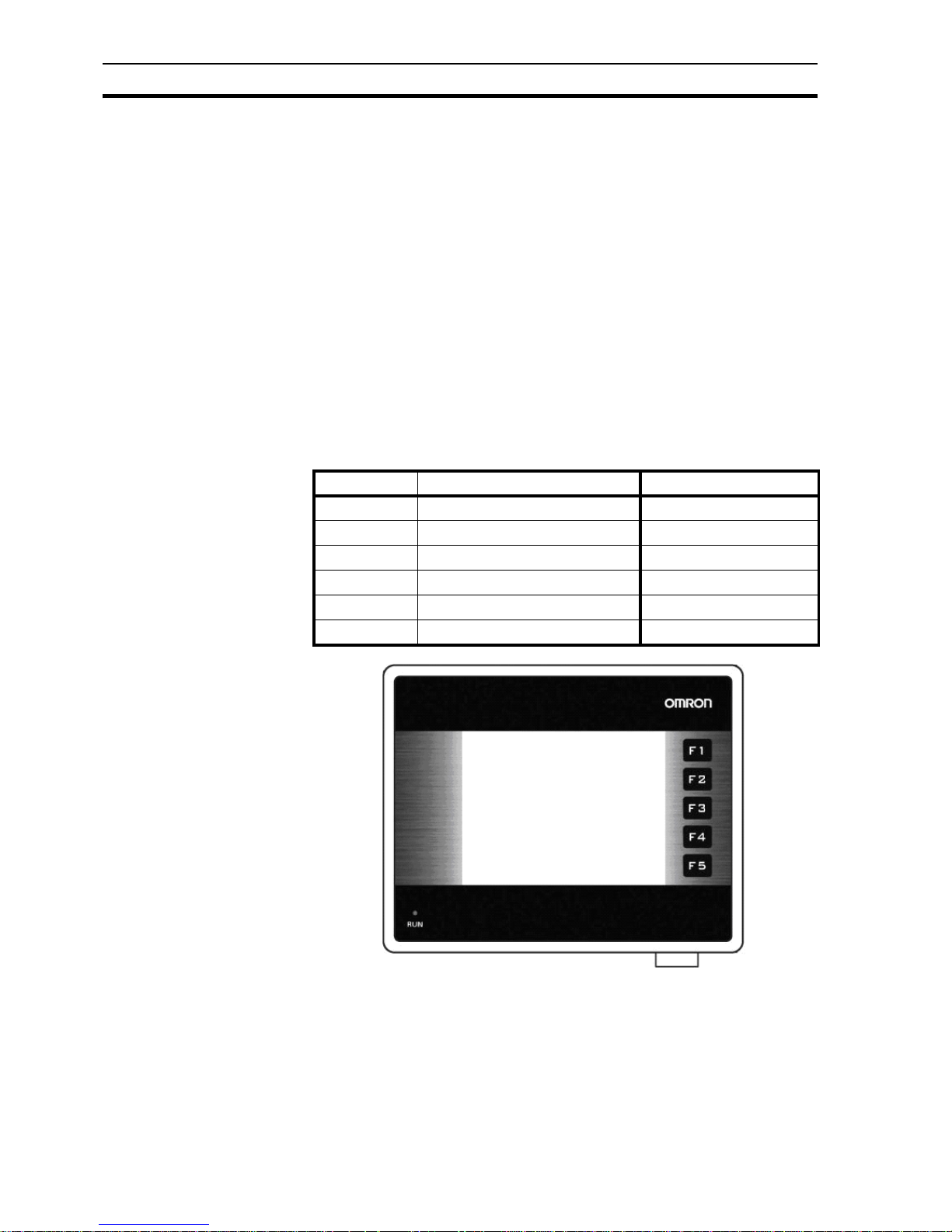
2-2 NQ-Series models
The NQ-Series are Human Machine Interfaces (HMIs) in three different
display sizes and two orientation models. Models included in the NQ-Series
are shown in Table 2.1: NQ-Series models. All models need +24 V
DC
power
from an external power supply.
/i
Table 2.1: NQ-Series models
Figure 2.1: Front view of a NQ-Series with 5 function keys
Model Description Orientation
NQ5-MQ000B 5.7” Monochrome STN blue mode Landscape
NQ5-MQ001B 5.7” Monochrome STN blue mode Portrait
NQ5-SQ000B 5.7” STN Colour Landscape
NQ5-SQ001B 5.7” STN Colour Portrait
NQ3-TQ000B 3.5” TFT Colour Landscape
NQ3-MQ000B 3.8” Monochrome STN blue mode Landscape
Page 17

Specifications for all models Section 2-3
3
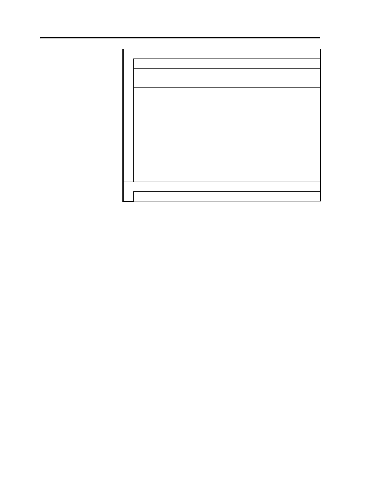
2-3 Specifications for all models
/i
Table 2.2: Common specifications for NQ-Series
Power supply
Input voltage 24 V
DC
Tolerance on input voltage +/− 15%
Display
Resolution (H * V) landscape models 320 * 240 pixels
Resolution (H * V) portrait models 240 * 320 pixels
Backlight life Min. 50000 hours at 25°C
Backlight saver Yes
Backlight dimming (NQ3) Using touch screen / Function Keys
Touch screen
Type 4-wire analogue resistive
Light transparency Min. 80%
Life Min. 5 million touches
Number of LEDs 1
Communication interfaces
RS-232/422/485 Yes
USB device Yes
USB host Yes
Processor 32-bit RISC (ARM)
Real-Time Clock (RTC) Yes (date and time)
Memory
Data register 1000
Retentive register 1400
System register 128
System coil 100
Internal coil 5000
Internal register 313
Battery
Type 3 V coin battery, with holder
Battery back-up Min. 5 years for RTC
Mounting
Method Panel mounting
Enclosure rating Front panel: IP65
Page 18
Specifications for all models Section 2-3
4
Environment
Ambient operating temperature 0 °C to 50 °C
Operating environment No corrosive gasses
Storage temperature -20 °C to 60 °C
Humidity 10% to 90%
1
relative humidity
(Noncondensing)
10% to 85%
2
relative humidity
(Noncondensing)
Noise immunity Conforms to IEC61000-4-4,
2 KV (power lines)
Vibration resistance (during operation) 5 to 8.4 Hz with 3.5 mm single amplitude
and 8.4 to 150 HZ with 9.8 m/s
2
acceleration 10 times in each of X, Y and Z directions
Shock resistance (during operation) 147 m/s
2
3 times in each of X, Y and Z
directions
International standards
Directives CE, cULus
1. At 25 °C ambient temperature.
2. 85% at 40 °C ambient temperature. Above 40 °C the equivalent absolute humidity is less than 85%.
Page 19
Specifications per model Section 2-4
5
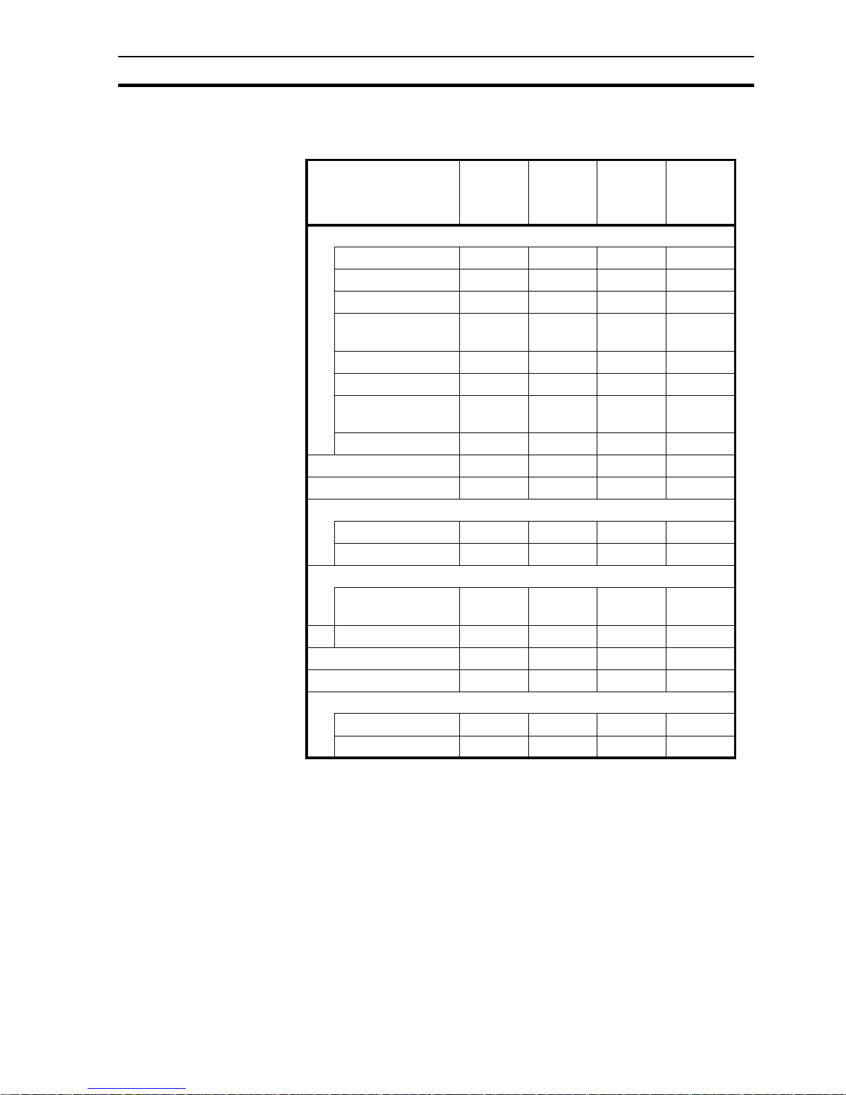
2-4 Specifications per model
/i
Table 2.3: Specifications per NQ-Series model
Model NQ5-
MQ000B/
NQ5MQ001B
NQ5SQ000B/
NQ5SQ001B
NQ3TQ000B
NQ3MQ000B
Display
Display size 5.7 “ 5.7 “ 3.5 “ 3.8 “
Display type STN STN TFT STN
Monochrome/colour Mono Colour Colour Mono
Colours supported 16
gradations
256
colours
1
1. 4096 colours for bitmaps
256
colours
2
2. 32000 colours for bitmaps
16
gradations
Brightness (Cd/m2) Min. 200 Min. 200 Min. 200 Min. 160
Contrast ratio 4 55 300 3
Contrast adjustment
using touch screen
Yes Yes No Yes
Backlight types CCFL CCFL LED LED
Touch screen size 5.7 “ 5.7 “ 3.5 “ 3.8 “
Function keys 6655
Memory
Total (MB) 8884
Program (MB) 6.7 6.7 6.7 2.6
Communication interfaces
RS-232/485/422 port
(Com 1)
Yes Yes Yes Yes
RS-232 port (Com 2) Yes Y es NA NA
Power rating (W) 10101010
Weight 0.7 kg max. 0.7 kg max. 0.3 kg max. 0.3 kg max.
External dimensions
Width * Height (mm) 195 * 142 195 * 142 128 * 102 128 * 102
Thickness (mm) 50 50 44.5 44.5
Page 20

Specifications per model Section 2-4
6
Page 21

Section
7
SECTION 3
Installation and wiring
This section describes how to install the NQ-Series and how to wire the HMI.
SECTION 3
Installation and wiring 7
3-1 Installation notes .............................................................................. 8
3-2 Mounting .......................................................................................... 9
3-3 Wiring ............................................................................................... 12
3-4 Multi-drop networks .......................................................................... 15
Page 22

Installation notes Section 3-1
8
3-1 Installation notes
For improved reliability and maximized functionality, take the following
information into consideration when installing a NQ-Series HMI.
3-1-1 Location
Do not install the NQ-Series in the following locations:
• Areas subject to explosion hazards due to flammable gasses, vapours and
dusts.
• Areas subject to dramatic temperature changes. Temperature changes can
cause condensation of water in the device.
• Areas with an ambient temperature lower than 0 °C or higher than 50 °C.
• Areas subject to shock or vibration.
3-1-2 Temperature control
• Provide adequate space for air flow.
• Do not install the NQ-Series above equipment that generates significant
heat.
• If the ambient temperature exceeds 50 °C, install a cooling fan or air
conditioner.
3-1-3 Accessibility
• For safety during operation and maintenance, mount the NQ-Series as far
as possible from high-voltage equipment and power machinery.
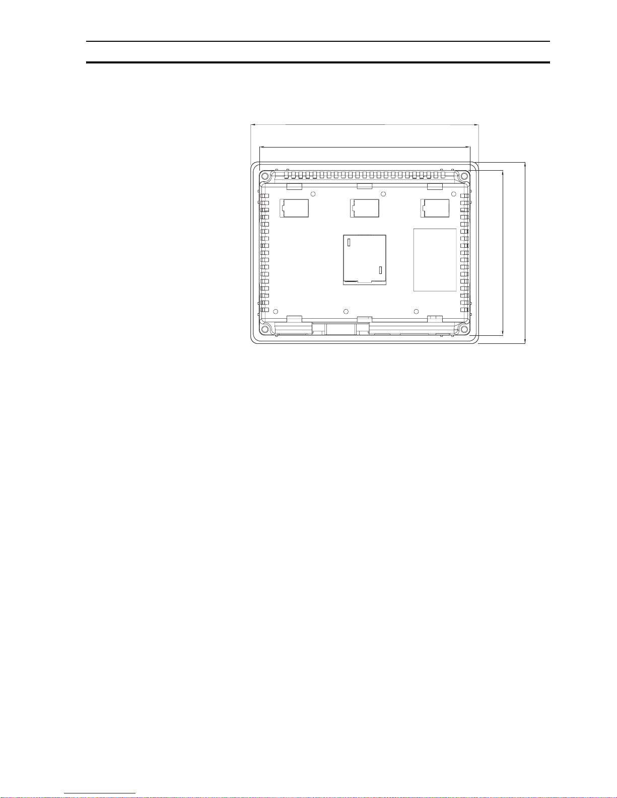
3-1-4 Panel cut-out
Before the NQ-Series can be mounted, a rectangular cut-out must be made in
the panel in which the NQ-Series will be mounted. Table 3.1: Dimensions of
NQ-Series and required panel cut-out shows the dimensions and tolerances of
the NQ-Series, the panel and the required cut-out.
/i
Table 3.1: Dimensions of NQ-Series and required panel cut-out
Above external dimensions and cut-outs are for landscape models.
For portrait models exchange the W and H sizes. For portrait models the
cables will be mounted to the left side of the NQ-Series (view from front).
NQ5- NQ3-
Display size 5.7 “ 3.5 “ and 3.8 “
External dimensions: W
ext
195 mm 128 mm
H
ext
142 mm 102 mm
Panel cut-out: W
cut-out
184.00 mm 119.00 mm
H
cut-out
131.00 mm 93.00 mm
Panel cut-out tolerance +0.50 mm +0.50 mm
Panel thickness Max. 6.0 mm Max. 6.0 mm
Page 23
Mounting Section 3-2
9
Figure 3.1: Dimensions of NQ-Series and required panel cut-out (landscape).
3-2 Mounting
The NQ-Series has been developed for panel mounting.
Delivered mounting set with each NQ-Series contains:
• 4 mounting clamps
• A green power connector
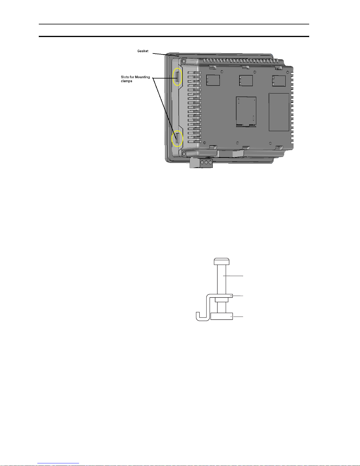
• A sealing gasket (already mounted on the NQ)
Use the delivered mounting set for proper installation. After the preparation of
the panel, the NQ-Series can be mounted using the supplied clamps. The NQSeries comes with a gasket pre-installed behind the bezel, as shown in Figure
3.2: NQ-Series with gasket and mounting clamp slots.
H
ext
H
cut-out
W
ext
W
cut-out
Page 24
Mounting Section 3-2
10
Figure 3.2: NQ-Series with gasket and mounting clamp slots
Mount the NQ-Series as follows.
1 Locate the four mounting clamp slots in the case of the NQ-Series. The
NQ3 models have their slots located at the side surfaces of the case (as
shown in Figure 3.2: NQ-Series with gasket and mounting clamp slots. The
slots of the NQ5 models are located at the top and bottom surfaces of the
case.
2 Keep the four mounting sets at hand. Each set consists of a screw (1), a
clamp (2) and a cap (3) as shown in Figure 3.3: Mounting hardware set.
Figure 3.3: Mounting hardware set
3 Insert the case into the cut-out in the panel, from the front side of the panel.
4 Insert a clamp into a mounting clamp slot on the case and tighten the screw
slightly as shown in Figure 3.4: Case being fixed in panel.
1
2
3
Page 25

Mounting Section 3-2
11
Figure 3.4: Case being fixed in panel
5 Repeat previous step for the other three clamps.
6 Hold the NQ-Series straight and tighten all four screws evenly to a torque
between 0.5 Nm and 0.6 Nm.
Page 26
Wiring Section 3-3
12
3-3 Wiring
NQ-Series models have, besides one power connector, a number of
communication ports. Please refer to Table 2.2: Common specifications for
NQ-Series and Table 2.3: Specifications per NQ-Series model for the
availability of these ports on each of the NQ-Series models.
!Caution
If wiring is to be exposed to lightning or surges, use appropriate surge suppression
devices. Keep AC, high energy and rapidly switching DC wiring separate from signal
wires.
!WARNING Connecting high voltages or AC power mains to the DC input will make the NQ Series
unusable and may create an electrical shock hazard to personnel. Such a failure or
shock could result in serious personal injury, loss of life and/or equipment damage. DC
voltage sources should provide proper isolation from main AC power and similar
hazards.
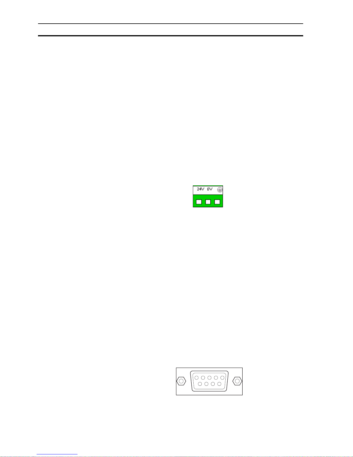
3-3-1 Power connector
All NQ-Series models have a 3-pin, Green coloured, power connector with pin
layout as shown in Figure 3.5: Power connector. Wire the inputs of the power
connector according to the pin layout, from left to right: +24 V
DC
(DC+), 0 V
(DC−) and Earth.
Figure 3.5: Power connector
3-3-2 Communication ports
The serial communication ports have two functions:
1 To connect to programming devices during configuration.
2 To communicate with a PLC and other devices in operating mode.
NQ-Series communication ports support various types of (serial)
communication.
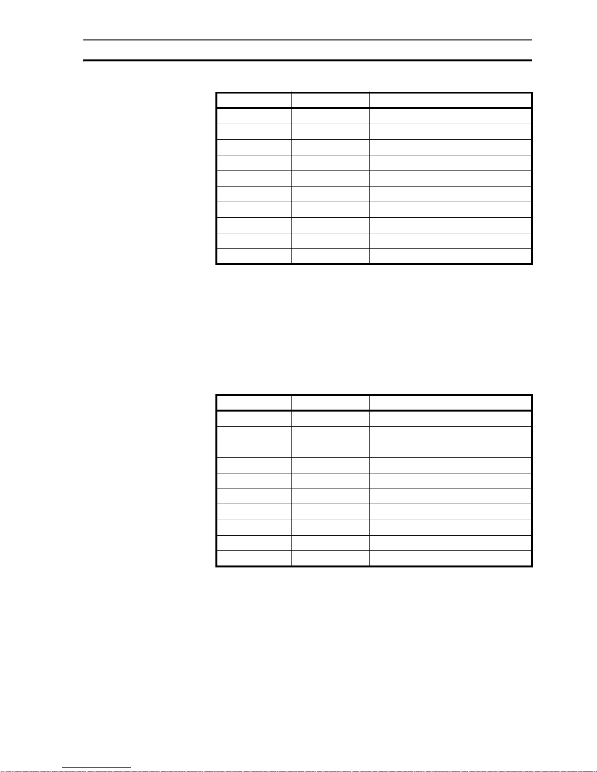
3-3-2-1 COM1 port
COM1 is an integrated RS-232 and RS-485/RS-422 communication port. It
communicates with external peripherals devices at baud rates of 4800 kbps to
187.5 kbps with none, even or odd parity.
RS-485/RS-422 can be used in multi-drop (networks with more than one NQSeries or PLC) communication networks.
The connector is a standard D-type 9-pin female connector (see Figure 3.6: 9pin sub-D connector) with pin layout as shown in Table 3.2: Pin layout of port
COM1.
Figure 3.6: 9-pin sub-D connector
/i
Page 27
Wiring Section 3-3
13
Table 3.2: Pin layout of port COM1
3-3-2-2 COM2 port
COM2 is a RS-232 communication port. It communicates with external
peripherals at baud rates of 4800 kbps to 115.2 kbps with None, Even or Odd
parity.
The connector is a standard D-type 9-pin female connector (see Figure 3.6: 9pin sub-D connector) with pin layout as shown in Table 3.3: Pin layout of port
COM2.
/i
Table 3.3: Pin layout of port COM2
Pin number Pin name Description
1 TX+ RS-422 transmit +
2 TXD RS-232 transmit
3 RXD RS-232 receive
4 RX+ RS-422 receive +
5 GND Signal Ground
6 NC Not connected
7 NC Not connected
8 TX− RS-422 transmit -
9 RX− RS-422 receive -
shell shield
Pin number Pin name Description
1 NC Not connected
2 TXD RS-232 transmit
3 RXD RS-232 receive
4 NC Not connected
5 GND Signal Ground
6 NC Not connected
7 NC Not connected
8 NC Not connected
9 NC Not connected
shell shield
Page 28
Wiring Section 3-3
14
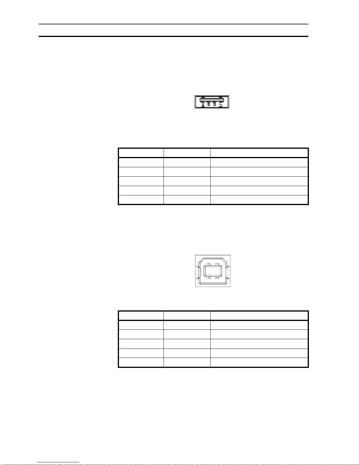
3-3-2-3 USB host port
The USB host port is compliant with the USB 2.0 specification. The USB host
port supports USB memory stick devices. The USB sticks can be used for data
logging and program upload/download, and carrying print files in CSV format.
The connector is a standard USB type A female connector as shown in Figure
3.7: USB host connector.
Figure 3.7: USB host connector
Pinning of the USB host port is described in the table below.
/i
Table 3.4: Pin layout of USB host port
3-3-2-4 USB device port
The USB device port is compliant with the USB 2.0 specification for selfpowered devices.
The connector is a standard USB type B female connector as shown in Figure
3.8: USB device connector.
Figure 3.8: USB device connector
/i
Table 3.5: Pin layout of USB device port
Pin number Pin name Description
1 VBUS +5V
2 D- Data -
3 D+ Data +
4 GND Signal ground
shell shield
Pin number Pin name Description
1 VBUS +5V
2 D- Data -
3 D+ Data +
4 GND Circuit ground
shell shield
Page 29
Multi-drop networks Section 3-4
15
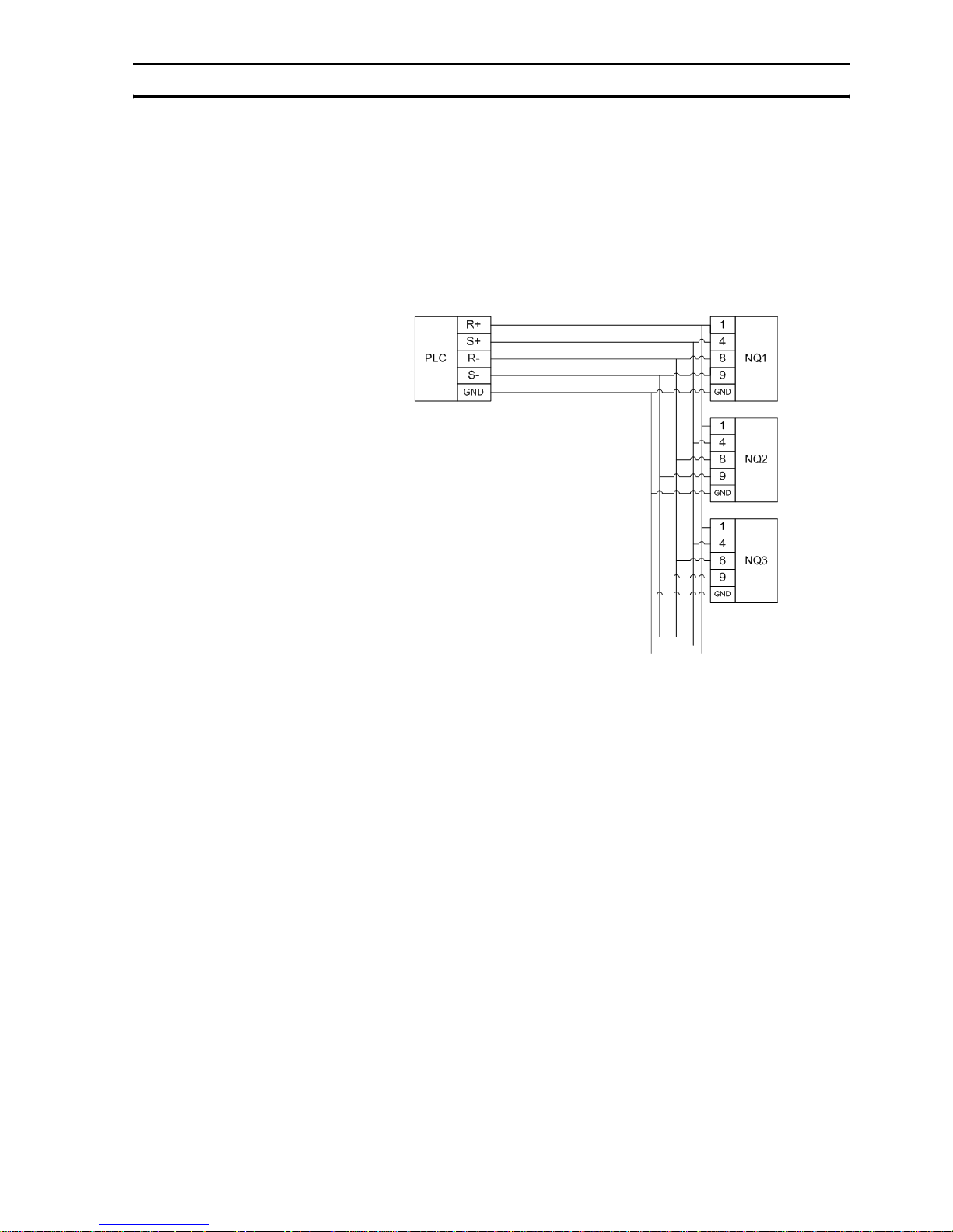
3-4 Multi-drop networks
Several NQ-Series can be set up in a network. The following wiring diagrams
show the correct connections:
• RS-422 interface
• RS-485 interface
3-4-1 RS-422 network
The following wiring diagram is applicable for a RS-422 network (4-wire).
Figure 3.9: RS-422 network
Page 30
Multi-drop networks Section 3-4
16
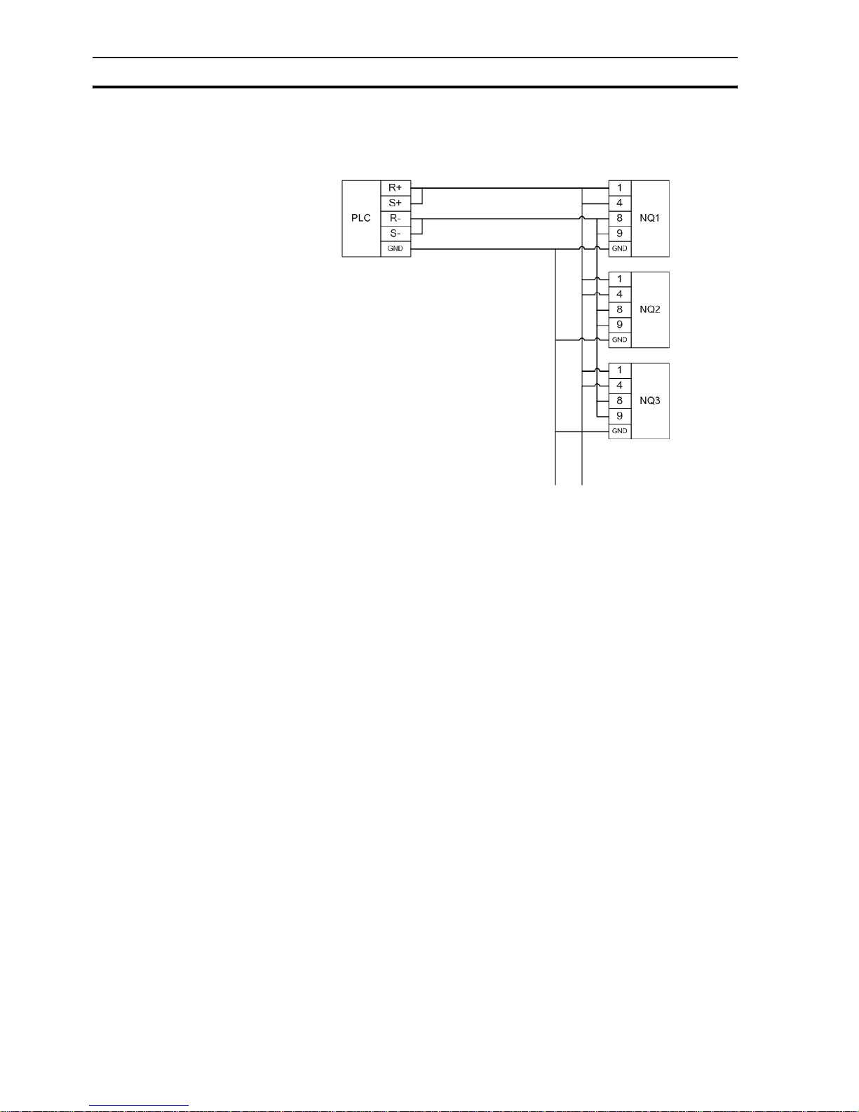
3-4-2 RS-485 network
The following wiring diagram is applicable for a RS-485 network (2-wire).
Figure 3.10: RS-485 network
3-4-3 Network termination
The two ends of a multi-drop network have to be terminated. For the correct
termination of the last NQ-Series in the network, a resistor (120 Ohm) needs
to be applied between R+ (pin 4) and R- (pin 9) on DSUB9 (Male) cable
connector for correct termination.
Page 31

Section
17
SECTION 4
Creating applications
This section describes how to create programs for the NQ-Series.
SECTION 4
Creating applications 17
4-1 Preparing for programming .............................................................. 18
4-2 Using NQ-Designer .......................................................................... 21
4-3 Example application .........................................................................33
Page 32
Preparing for programming Section 4-1
18
4-1 Preparing for programming
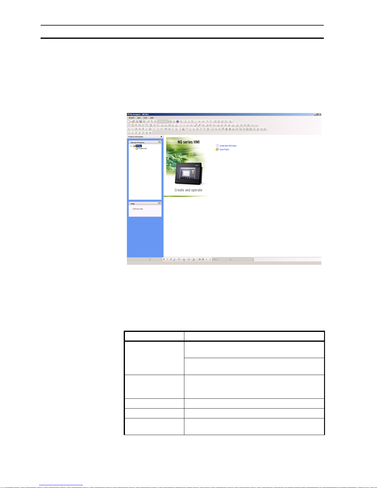
4-1-1 NQ-Designer
NQ-Designer is used to create and modify user interfaces for the NQ-Series.
The user interface is created in the software and downloaded to the device.
Existing user interfaces can be uploaded to the software and be modified as
required. The software can also be used in a simulation mode to test the
program without downloading the program to the NQ-Series.
Figure 4.1: NQ-Designer
4-1-2 System requirements
The following basic PC hardware configuration is needed to install and use
NQ-Designer.
4-1-2-1 Microsoft® Windows® XP configuration
/i
Table 4.1: Windows XP configuration
Device Recommendations
Processor Minimum: 600 MHz Pentium processor or
equivalent processor
Recommended: 800 MHz Pentium processor or
equivalent processor
Operating System Windows® 2000 with SP4,
Microsoft® Windows® XP Professional
Microsoft® Windows® XP Home Edition with SP2
System RAM Minimum: 128 MB
Recommended: 256 MB/512 MB
Hard Disk Space 800 MB
(including 200 MB for the .NET Framework Redistributable)
Page 33

Preparing for programming Section 4-1
19
4-1-2-2 Microsoft® Windows® Vista configuration
/i
Table 4.2: Windows Vista configuration
4-1-3 Installing the software
To install NQ-Designer run setup.exe from the installation disc and follow the
installation instructions.
4-1-4 Connecting the NQ-Series power supply
Connect a 24 VDC power supply to the NQ-Series.
4-1-5 Connecting the NQ-Series to a PC
The NQ-Series can be connected to a PC with the following programming
cables:
• Serial cable (NT2S-CN002)
• USB cable (CP1W-CN221)
Refer to Appendix A-2 and A-4 for more information on cables.
4-1-5-1 Serial cable
The serial cable can be used directly after connecting the cable.
Display Minimum: 800 x 600 with 256 colours
Recommended: 1024 x 768 with 16 bit colour quality
Serial Port Serial port or USB port
Mouse Microsoft® Mouse or compatible pointing device
Keyboard Required
Device Recommendations
Device Recommendations
Processor Minimum: 800 MHz Pentium processor or
equivalent processor
Recommended: 1 GHz Pentium processor or
equivalent processor
Operating System Microsoft® Windows® Vista Home
Microsoft® Windows® Vista Business Edition
System RAM Minimum: 512 MB
Recommended: 1 GB
Hard Disk Space 800 MB
(including 200 MB for the .NET Framework Redistributable)
Display Minimum: 800 x 600 with 256 colours
Recommended: 1024 x 768 with 16 bit colour quality
Serial Port Serial port or USB port
Mouse Microsoft® Mouse or compatible pointing device
Keyboard Required
Page 34

Preparing for programming Section 4-1
20
4-1-5-2 USB cable
In order to use a USB cable the USB driver needs to be installed on the PC
operating system. Perform the following steps to install the USB driver.
1 Connect the USB cable to the PC and NQ-Series.
2 When the PC detects the NQ-Series the following message is displayed:
Found New Hardware: HMI USB Device.
On the dialog select Found New Hardware Wizard, No, not this time
and click Next (It depends on the environment whether the message is
displayed or not.).
3Select Install from a list of specific location and click Next.
4 Ensure that Include this location in the search is checked and browse to
the following location:
C:\Program Files\OMRON\NQ-Designer\USBDrivers\
5Click Next to install the USB driver.
6 If the Hardware Installation dialog is displayed, click Continue Anyway.
7Click Finish to complete the installation.
A correct installed driver will show a message on the NQ-Series’ screen: USB
device status: Connected (This message is only shown when no firmware is
downloaded in the NQ).
Page 35

Using NQ-Designer Section 4-2
21
4-2 Using NQ-Designer
4-2-1 Starting NQ-Designer
Select Start, Programs or All Programs, Omron and click on NQ-Designer
to start the program.
4-2-2 NQ-Designer program window
Opening a project or creating a new project will show the below programming
window on your Personal Computer.
Figure 4.2: NQ-Designer program window
4-2-2-1 Title bar
The title bar displays the name of the program and the selected part of the
project.
4-2-2-2 Menu bar
The menu bar contains the program commands.
4-2-2-3 Toolbars
The toolbars contain shortcuts to all program functions.
To display the tool tips hover over the icons in the toolbars.
On the View menu click Too lba rs to hide or show a toolbar. The toolbars
supporting drag and drop functionality.
4-2-2-4 Project panel
The project panel shows the structure of the program. From the project
structure the project is managed and the project parts are set and configured.
On the View menu click Projects Information to hide or show the project
panel.
Page 36

Using NQ-Designer Section 4-2
22
Project list
The Project list contains all saved projects. The project file extension is .NQP.
Creating or opening a project will show the root folders described below.
Screens
The Screens folder contains one base screen and four predefined keypad
screens that can be used in the project. For every screen the following parts
can be configured:
• Layout: graphical representation of the screen
• Keys: function keys used in this screen
• Tasks: assigned tasks to the screen
• Password: a password can be assigned to pages that must be entered
before the page can be accessed.
Keypad screens and screens numbered 65000 and higher are assigned as
pop up screens. If a new popup screen is added to the project the screen will
be located here.
Functions that can not be assigned to pop up screens are:
• Goto next screen
• Goto previous screen
• Open popup screen (it is not allowed to chain pop up screens)
• Data entry objects
• All objects configured to PLC tags
• Password protection
Tem p l a t es
The Tem p l a te s folder contains the created template screens. Template
screens are screens that can be added to a base screen. Template screens
are always placed behind the base screen. These screens usually contain
keys, buttons or background images that are used frequently in the project.
Following objects can not be assigned or are conditional to template screens:
• Data Entry on PLC tags
• Keypads placed on template screens act on numerical input of the base
screen
• Screen tasks ( Before showing, while showing, after hiding tasks)
• Key specific tasks
• Objects related to PLC tags
• Passwords
Using templates will also positively influence the usage of the memory and
reduce the programming time. (You re-use screens that you have
programmed before and assign them to different base screens).
To add a template proceed as follows:
• Click on ADD Templates ( ).
Page 37

Using NQ-Designer Section 4-2
23
Global Keys
The Global Keys folder can be used to assign tasks to global keys. Global
keys are running cyclic for the whole project. The following tasks are available:
• Press Task (tasks executed while pressing the key)
• Pressed Tasks, (tasks executed while holding the key)
• Released Tasks (tasks executed while releasing the key)
Please note that when key tasks are assigned to screen keys the global keys
will not be executed, e.g. global key F1 = add 1 to D000, and screen key F1 =
subtract 1 from D000 then subtract 1 is active for this screen when pressing
F1.
Tasks
On the Tasks dialog the Power On tasks and Global tasks can be configured.
The Power On tasks are executed once the NQ-Series starts up. The Global
tasks are executed every cycle of the program. The task list can contain more
than one command.
Global tasks that most common used are:
• Switch SCREEN from TAG (used when the PLC is responsible for screen
switching).
• Copy RTC to PLC (this copies the NQ-Series’ RTC data to assigned PLC
tags (7 sequential tags)).
If the program contains many global tasks it can influence the performance of
the NQ-Series.
Tag s
The folder Tags shows all tags that can be used in the project. The folder
contains the following tags: system tags (default set), internal tags (NQ tags)
and PLC tags created by users.
Tags represent the addresses (bit, byte, word, double word registers) that will
be used in a project.
Page 38

Using NQ-Designer Section 4-2
24
To add a tag proceed as follows.
•Click Tag ( )in the toolbar and click Add....
Figure 4.3: Tag information
• Enter Tag Name.
•Select Register/Coil Type.
•Select Tag Typ e .
•Select Auto Add to create a number of tags in sequence increasing by
word or by bit depending on tag choice. ( names can be edited afterwards)
•Select 2-Bytes (1-word).
Default system tags
The following tables contain the default system tags. Do not attempt to modify
or delete the system tags. This could affect the functionality of the NQ-Serie.
On the toolbar you find a button ( ) that allows you to display all tags or
user created tags shown in your tag list.
/i
Table 4.3: Default system tags (words)
Register Tag name Read/Write Description
S0001 Language Read/Write Writing a value will change
languages in multi language
supported objects (texts).
S0002 Flash memory status Read Shows percentage used of
logger memory.
S0004 Number of historical
alarms
Read Shows number of alarms
stored in history.
S0005 Screen trigger register Read/Write Shows active screen.
Change screen by writing a
valid screen number in the
register.
S0006 Screen saver time Read/Write The screen saver time (Sec)
can be changed during
operation.
Page 39

Using NQ-Designer Section 4-2
25
/i
Table 4.4: Default system tags (Bit)
S0010 RTC day Read RTC day in integer format
S0011 RTC month Read RTC month in integer format
S0012 RTC year Read RTC year in integer format
S0013 RTC hour Read RTC hour in integer format
S0014 RTC min Read RTC minute in integer format
S0015 RTC sec Read RTC second in integer format
S0016 RTC day of the week Read RTC day of week in integer
format
S0017 Scan time register Read Shows time required to
execute screen, screen task
and global task in millisecond.
Use ####.## format for
display.
S0018 Communication recover
time[s] for port1
Read/Write Shows time in seconds to
recover the communication
with failed nodes for port1. The
default value is 60 sec.
S0020 Driver scan time register
for port1
Read Shows time required to
execute screen blocks in
milliseconds. Use ####.##
format for display.
S0023 Popup screen trigger
register
Read/Write Holds the screen number for
the pop-screen that will be
shown when bit s20 bit is set.
S0116 Fact_Appln_1 Read/Write Reserved
S0117 Fact_Appln_2 Read/Write Reserved
S0118 Fact_Appln_3 Read/Write Reserved
S0119 Fact_Appln_4 Read/Write Reserved
S0120 Fact_Appln_5 Read/Write Reserved
S0121 Contrast control
(Retentive register)
Read/Write This retentive register used for
setting the contrast of the NQSeries.
S0122 Brightness control
(Retentive register)
Read/Write This retentive register used for
setting the brightness of the
NQ-Series.
S0123 Fact_Appln_6 Read/Write Reserved
S0124 Fact_Appln_7 Read/Write Reserved
S0125 Fact_Appln_8 Read/Write Reserved
Register Tag name Read/Write Description
S0003_00 Logger memory full status Read 1: full memory
S0003_01 Logger memory clear
status
Read 1: memory clear is
being executed
Register Tag name Read/Write Description
Page 40

Using NQ-Designer Section 4-2
26
S0003_02 RTC fail Read RTC fail (contents of
registers not within
defined ranges e.g.
minutes>60 )
S0003_14 Comm1 status Read 0: communication error
1: communication OK
S0003_15 Comm2 status Read 0: communication error
1: communication OK
s0003 Minute change pulse Read 1 for every change in
minute for one scan
cycle
s0004 Hour change pulse Read 1 for every change in
hour for one scan cycle
s0005 Date change pulse Read 1 for every change in
date for one scan cycle
s0006 Month change pulse Read 1 for every change in
month for one scan
cycle
s0007 Year change pulse Read 1 for every change in
year for one scan cycle
s0008 Screen saver control Read/Write 0: disable screen saver
1: enable screen saver
This bit can be changed
in during operation
s0009 Beeper on/off Read/Write 0: disable beeper
1: enable beeper
This bit can be changed
during operation.
s0010 Battery status Read 0: battery voltage is OK
1: low battery
(below 2.2 V)
s0012 Update the historical trend Read/Write Update the historical
trend window when set
to 1
s0014 Acknowledge all alarms Read 0: all alarms are
acknowledged
1: all alarms are not
acknowledged in the
real and historical
alarms
s0016 Valid key beeper Read/Write 0: disable valid Function
key beeper
1: enable valid Function
key beeper
This bit can be changed
during operation
Register Tag name Read/Write Description
Page 41

Using NQ-Designer Section 4-2
27
s0017 Invalid key beeper Read/Write 0: disable valid screen
beeper
1: enable valid screen
beeper.
When set to 0 the NQSeries will only generate
a beep when an input
area is pressed.
This bit can be changed
during operation
s0019 Invalid date entry Read 0: valid date
1: invalid date (range
not within defined
ranges e.g. month > 12)
s0020 Popup screen control coil Read/Write Triggers the popup
screen number stored in
S0023
s0021 Communication recover
enable bit: port1
Read/Write If this bit is set
communication with the
failed nodes is detected
after scan time S0018
for port1 (on by default)
s0028 Bittask datalogger-logger
group1 bit
Read/Write User can start/stop
logging in bit task mode
for group1 by using this
bit.
1: Start logging
0: Stop logging
s0029 Bittask datalogger-logger
group2 bit
Read/Write User can start/stop
logging in bit task mode
for group2 by using this
bit.
1: Start logging
0: Stop logging
s0030 Bittask datalogger-logger
group3 bit
Read/Write User can start/stop
logging in bit task mode
for group3 by using this
bit.
1: Start logging
0: Stop logging
s0031 Bittask datalogger-logger
group4 bit
Read/Write User can start/stop
logging in bit task mode
for group4 by using this
bit.
1: Start logging
0: Stop logging
s0032 Lock data entry Read/Write User can lock/unlock
the data entry (keypad
entry).
0: data entry unlock
1: data entry lock
Register Tag name Read/Write Description
Page 42

Using NQ-Designer Section 4-2
28
Nodes
The Nodes folder contains the information of your network: the name of the
panel and PLCs, node addresses in the network (listed under COM1 or
COM2), protocol used on the COM port. COM1 and COM2 can have different
protocols.
In this folder you can also add a node to your network.
•Click Nodes ( ).
• Right-Click on screen.
• Select add Node.
4-2-2-5 Alarms
In the alarm folder alarms can be assigned and configured.
For alarms there can be chosen of two formats to configure.
• 16 Random words
For each TAG (word) 16 alarms can be configured / assigned in the alarm
folder.
A total of 16 different words ( = 256 alarms) can be configured / assigned.
• 16 consecutive words
This function is enabled after 16 consecutive Word tags have been created
in the tag database. If this method is chosen all 256 lines will be created in
your alarm screen.
s0033 Start data entry only
through enter key
Read/Write User can choose the
mode of data entry
using this bit.
0: allow data entry
through enter key or
numeric key
1: allow data entry only
by pressing enter key
first
s0035 Ignore real and historical
alarms
Read/Write 0: Monitor all alarms
1: Ignore all real and
historical alarms
s0036 Run LED on/off Read/Write 0: Run Led is On
1: Run Led is Off
s0037 Allow USB host operation Read/Write 0: USB host operation
not allowed
1: USB host operation
allowed.
Register Tag name Read/Write Description
Page 43

Using NQ-Designer Section 4-2
29
Attached image shows a screenshot of the alarm screen.
Figure 4.4: Alarm project configuration properties
Above image shows the window that is shown when opening the alarm folder.
From top to bottom you see:
• Alarm type: 16 random words (this is the selection made in the alarms tab
starting the project)
• Also action, If alarm memory is full, this is also selected in the alarm tab,
and the action that is performed.
• Acknowledge alarms on selection, this means that for each alarm an
acknowledge bit must be selected.
If any of the selections made above is incorrect, press button Change
properties.
Note that this will erase any alarm assignments already created.
For assigning the alarm register that will be used to trigger alarms a tag has to
be created in tag list.
Example:
HR000 is the alarm register used in the PLC program. Create a tag with
HR000 in your tag list. Select this created tag and assign the alarm register.
Upon assigning you will see that the first 16 lines are now identified as alarms.
Bit HR000.00 as alarm 0 (Motor stopped), bit HR000.01 as alarm 1 (Fuse
blown), etc.
Clicking on alarm 0 first line allows you to enter the alarm text, acknowledge
(Y/N) and which bit should be used to perform ACK, severity, real time alarm
or Historical alarm.
When all of these settings are made you click button ACCEPT. You see now
all text turns blue and alarm sign has changed to YES.
With this method you can assign all alarms used in your project.
Page 44

Using NQ-Designer Section 4-2
30
Important buttons are explained below for assigning alarms.
Figure 4.5: Alarm buttons
• Update will update the change you have applied to the alarms
• Delete will delete the alarm line you have selected.
• Reset all alarms will reset all settings in alarms. All will be cleared including
the selected register for alarms
• Export will export all text used in alarms to CSV for creation of
Multilanguage application.
• Import will import the modified CSV file for multilanguage in the project.
4-2-2-6 Data Logger
The data logger allows users to log data (tags) in the NQ-Series over time.
The data logger folder contains the set-up/configuration for data logging and
data logging printing.
Figure 4.6: Data logger
Page 45

Using NQ-Designer Section 4-2
31
The memory size reserved for logging data in the terminal can be selected.
Several ranges can be selected from 256Kb to 2048Kb.
For logging the data type (word / double word) can be selected. Upon this
selection the tags available for logging will then be filtered to what can be
chosen for logging.
The data logger allows a user to define 4 different groups. Each group can
contain of 30 tags that can be logged. For each group a logging mode can be
defined.
The datalogger can handle 6 different logging modes.
• Power up
Each tag defined in this group will be logged when terminal is powered and
application is running. The logging frequency for this group can be set.
• Start / Stop time
User can define on which part of the day the logging must occur. Also with
this option the logging frequency can be programmed for the whole group
when choosing this mode.
•Key task
User can assign keys / buttons to start and stop logging. The commands
can be found under "Keys specific Task" selection.
• Logging with run time frequency
This mode can only be used for group 1 and is intended for datalog printing
only. When selected this option each tag will be logged with a selectable
interval of minimum 30 minutes.
•Bit task
User can use the system bits s28 (group1) to s31 (group4) to start or stop
logging. If system bit is set to 1 logging starts.
•Event based
User can select an internal bit for logging. There are 3 options to select. :
Positive edge, Negative edge, Both edges. When selecting each of these
options the logging will start / stop on the selected conditions.
4-2-2-7 Languages
The Languages dialog shows the supported languages and manages the
languages supported by the project. To support a language the language
needs to be added to the program. NQ-Designer supports a total of 9
languages. The default language of the program is the default language of the
operating system.
Figure 4.7: Languages
To add a language proceed as follows.
• Select the language from the Supported Languages list and click Add.
• Check the checkbox to enable keyboard layout for the selected language.
Page 46

Using NQ-Designer Section 4-2
32
In the language folder you will see S0001 displayed. In front of each added
language a value is shown. If the value in register S0001 is set to the value
shown in front of the added language the project will then be displayed in the
selected language.
First language shown in the language folder is the default language of your
Windows operating system. Languages can be added or removed from this
folder.
If you use the import/export tool for entering multiple languages you do not
need to enable the keyboards in this folder. A keyboard can be enabled if you
add the language to your Windows operating system. Languages can always
be added to the program in a later stage.
Creating a multi language application import / export functionality for
translation you will always have to export and import 2 different files.
Text objects (Import / export text objects in Toolbar) AND Alarm objects (in
alarm folder).
4-2-2-8 Workspace
The workspace is used to create and edit the projects. The properties panel
displays the properties of the settings. The properties can be changed by
clicking the properties’ value.
4-2-2-9 Status bar
The status bar contains additional information regarding scratch pad area and
the screen area coordinates. The scratch pad area is the total screen area
available for programming.
4-2-2-10 Properties window
The properties window shows the properties of the selected object. Properties
that can be changed by user are displayed in bold.
4-2-3 Using the help function
The help function is displayed by clicking Software help or Contents on the
Help menu.
Page 47

Example application Section 4-3
33
4-3 Example application
4-3-1 Project settings
1 Start NQ-Designer.
2 Click Create New Project or click Create New NQ Project on the Project
menu under New.
Figure 4.8: Select model
Page 48

Example application Section 4-3
34
3Select NQ3 in product pulldown list. Select NQ3-TQ000B as model type.
Click OK.
Figure 4.9: Project information
4 Enter the following project data:
• Project title: Example
Page 49

Example application Section 4-3
35
5 Click COM1 tab.
Figure 4.10: COM1
6 Enter the following communication settings:
• Protocol: Omron NT Link
• Model: CP1L
• Baud Rate: 115.2K
•Data Bits: 8
•Parity: Odd
•Stop Bits: 1
7 Click Add Node.
8 Click Alarm tab.
Page 50

Example application Section 4-3
36
Figure 4.11: Alarm
9 Enter the following alarm settings:
• 16 random words: Each bit of each random assigned word is an alarm
Page 51

Example application Section 4-3
37
10 Click Settings tab.
Figure 4.12: Settings
11 Enter the following settings:
• Screen Saver Enabled
12 Click OK.
Figure 4.13: NQ-Designer screen
Refer to 4-2-2-4 Project panel for information on the project panel content.
Page 52

Example application Section 4-3
38
4-3-2 Screen functionality
NQ-Designer automatically generates 5 screens:
• 1 base screen for programming
• 4 predefined keypad screens (pop-up screens)
The properties window can be used to change the properties. Properties
displayed in bold can be changed. The most important properties are as
follows:
• Tasks List
• Use Template
Proceed as follows:
1 Double-click Screens. Click Screen1.
2Click ... from Tasks List in the property panel.
3 Select task from pulldown menu.
For each screen you can define if actions should be made before , during
or after closing the screen
4-3-3 Multilingual text objects
Multilingual text objects are used to display texts. This object should be used
when programming a multilingual application. The most important properties
are as follows:
• Visibility Animation
• Font
•Flash
• Text Colour
Page 53

Example application Section 4-3
39
Proceed as follows:
1 Click Multilingual Text ( ).
2 Draw the multilingual text object on Screen1.
3 Press the space bar. This will open a field in the Status Bar of NQ-
Designer. This will allow you to enter text immediately.
Figure 4.14: Multilingual text objects
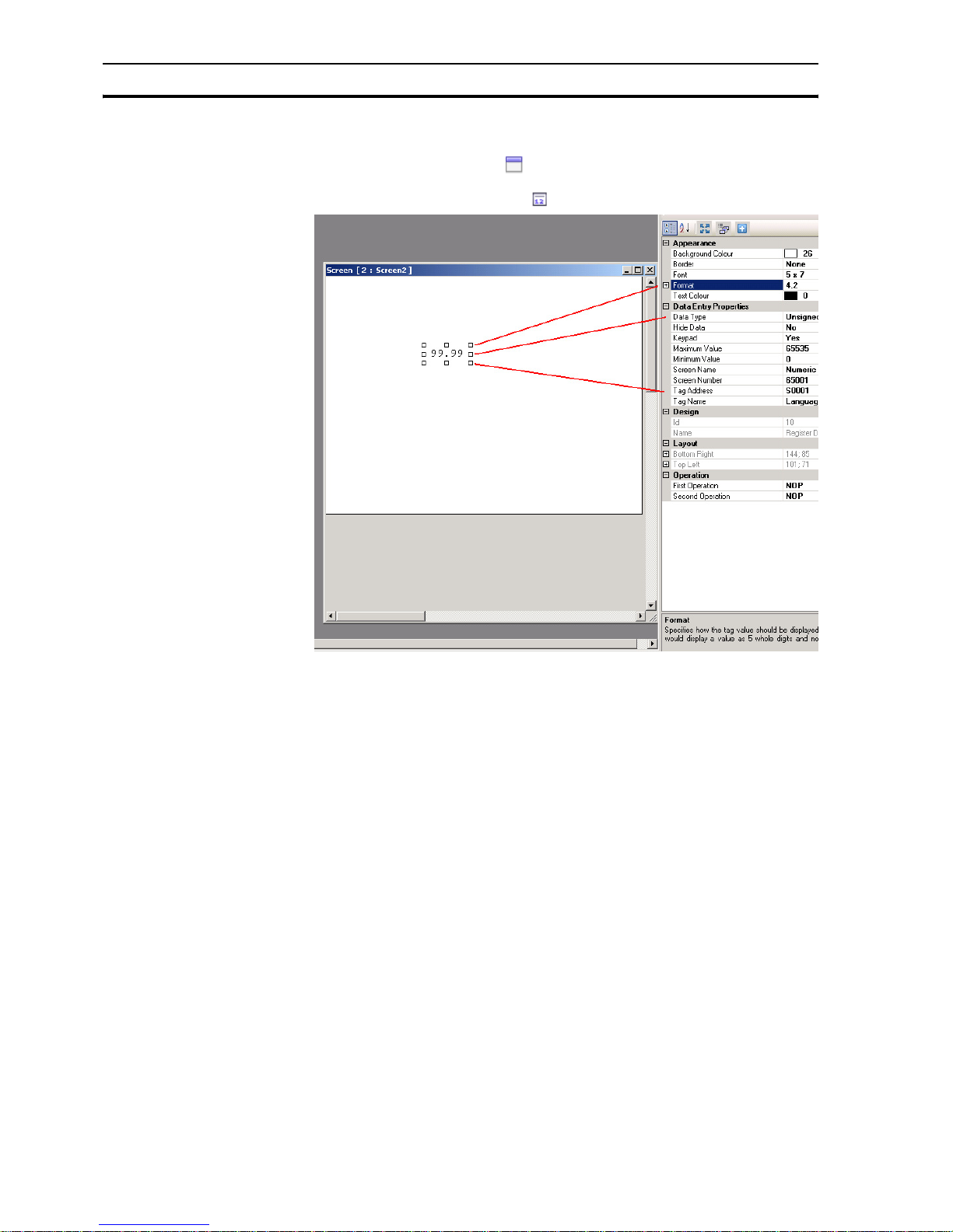
4-3-4 Data entry objects
Data entry objects will use a keypad to change data. In the property box a
popup screen ( keypad screen is automatically assigned with respect to format
used). If the user wants to add a keypad to base screen to change an input,
the setting keypad should be set to NO in the numerical input configuration
Data entry objects are used to enter:
• numerical data
•bit data
The most important properties for numerical data are as follows:
• Tag Address (register)
• Tag Name
• Data Type (unsigned, hex, binary, etc.)
• Format (4,2) total 4 digit of which are 2 behind the delimiter (**,**)
The most important properties for bit data are as follows:
•Off Text
•On Text
•Keypad
Page 54
Example application Section 4-3
40
Proceed as follows:
1 Right-click on Screens folder in project panel.
2Click New Base Screen ( ).
3 Click on Screen2.
4Click Numerical Data Entry ( ).
Figure 4.15: Data entry objects
Note Right lower field shows explanation of field selected in property box.
4-3-5 Display data objects
Display data objects are used to display:
• numerical data
• message data
•bit data
The most important properties for numerical data are as follows:
• Tag Address
• Tag Name
• Data Type
The most important properties for message data are as follows:
• Ranges
•On Text
• Tag Address
• Colour/Flash/Visibility Animation
The most important properties for bit data are as follows:
•Off Text
•On Text
• Tag Address
• Colour/Flash/Visibility Animation
Page 55

Example application Section 4-3
41
Proceed as follows:
1 Right-click on Screens folder in project panel.
2 Select New Base Screen ( )
3 Click on Screen3.
4 Click Numerical Data Display ( ).
5 Click on Screen3.
6 Click Message Data Display ( ).
7 Click 1 from Ranges in the property panel.
Figure 4.16: Display data objects
8 Click Add. (ranges can be modified to desired values)
Figure 4.17: Register text range
Page 56

Example application Section 4-3
42
4-3-6 Buttons
Buttons are used to assign tasks. The following buttons are available:
• Pre
defined buttons (
)
Buttons to which predefined single tasks can be assigned..
• Advanced bit button ( )
Free configurable bit buttons with feedback option. The following behaviour
can be programmed: press (rising edge), pressed (high) and released
(falling edge).
• Word button ( )
Buttons that can be configured on 32 states referenced to the value of the
used tag defined for each state. Different tasks and messages can be
assigned to each state of a word button.
The most important properties for buttons, advanced bit buttons and word
buttons are as follows:
• Button Style
•On Text
•On Text Colour
Proceed as follows:
1 Click on Screen3.
2Click Word Button ( ).
(Pressing the space bar will allow you to enter text directly.)
3Click Collection from State Properties in the property panel.
4Click Add State.
Figure 4.18: Word button
5Click ... from Tasks List in the property panel.
6Click Add.
Page 57

Example application Section 4-3
43
Figure 4.19: State properties
7 Click OK.
8 Click OK.
4-3-7 Lamp objects
The following lamp objects can be used:
• Bit lamp ( )
Bit lamp objects are used to display the on and off state of a coil type tag.
• Word lamp ( )
Word lamp objects are used to display multiple states (max. 32) depending
of the value of the assigned address.
The most important properties for bit lamp objects are as follows:
• Tag Address
• Style (generic, images, etc.)
• On Text Colour
The most important properties for word lamp objects are as follows:
• Tag Address
• State Properties
Proceed as follows:
1 Click Screen3.
2 Click Word Lamp ( ).
3 Click on Screen3.
4 Click ... from State Properties in the property panel.
Page 58

Example application Section 4-3
44
5Click Add State.
6Click OK.
Figure 4.20: Lamp objects
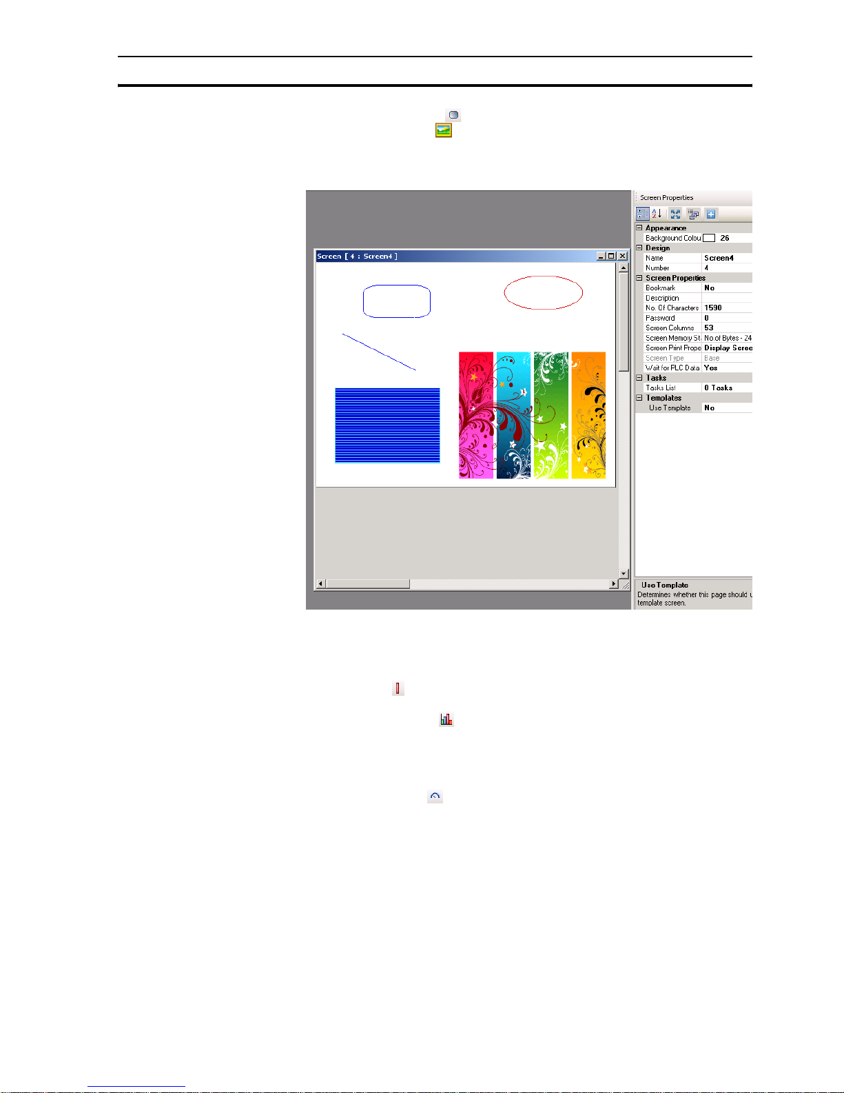
4-3-8 Graphical objects
The following graphical objects can be used to draw objects and place pictures
on the screen:
• Line ( )
•Rectangle ( )
• Ellipse ( )
Page 59
Example application Section 4-3
45
• Rounded rectangle ( )
• Advanced picture ( )
All imported pictures are converted to BMP before downloading the
pictures to the NQ-Series. This means that GIF and JPEG pictures will be
converted to BMP resulting in a bigger memory use.
4.21: Graphical objects
4-3-9 Wizards
The following wizards can be used to add functionalities:
• Bar graph ( )
To display a value by means of a bar.
• Multiple bar graph ( )
To display values by means of max. 4 bars in one graphic. Each bar can be
defined with different min. and max. values and assigned to different
addresses. See image attached with multiple bar graph properties
selected.
• Analogue meter ( )
To display a value by means of a meter.
Page 60

Example application Section 4-3
46
• Trend ( )
To display a value over a period of time in a diagram.
• Historical Trend ( )
To display the trend of logged data. This command can only be used if a
tag is logged in data logging. A maximum of 4 logged tags can be shown in
the historical trend.
Figure 4.22: Wizards
4-3-10 Alarms
Alarm windows are created for displaying alarms on screen. The most
important properties for alarms are as follows:
• Alarm Type (real time or historical)
• Select Display Fields ( what is shown and order)
Proceed as follows:
1Click Screen.
2Click Alarm ( ).
To define the alarm see Alarms in 4-2-2-4 Project panel.
3Click Collection from Select Display Fields in the property panel.
4Select On-Time and Off-time and click Add. The order of data shown in
the window can be configured here.
Page 61

Example application Section 4-3
47
Figure 4.23: Alarms
5 Click OK.
The tool bar contains four predefined alarm buttons: two buttons for navigation
and two buttons to acknowledge ( ). The acknowledge button
acknowledges the first alarm shown in the alarm window. The navigation
buttons are used to navigate through the alarm window.
4-3-11 Keypad
Keypads can be used on a popup screen or on the base screen. If used on a
popup screen the keypad will behave exactly the same as the predefined
keypads in NQ-Designer.
If the keypads are placed on a base screen where also an input is placed
(select No keypad in the property box), the keypad will change the data of this
input. If a keypad is placed on a base screen with more input fields it will
change all input fields on that screen one by one. To enable the keypad on a
base screen press ENT or one of the numeric keys. The first numerical input
will start to flicker. Now you can start entering the data.
Page 62

Example application Section 4-3
48
The following keypad can be used:
• Keypad ( )
This keypad is a numeric keypad that provides different styles of displaying
keypads.
• ASCII keypad ( )
This keypad is an ASCII keypad. There are two keypad styles:
ASCII (Style 1) and ASCII numeric (Style 2).
• Custom keypad ( )
This keypad can be selected to create a custom numeric or ASCII keypad.
The format can be freely chosen. This means merging keys, number of
keys. Assignments for keys can be chosen in the property box.
Page 63

Section
49
SECTION 5
Transferring programs
This section describes how to transfer NQ-Designer programs to NQ-Series
models.
SECTION 5
Transferring programs 49
5-1 Downloading..................................................................................... 50
5-2 Uploading ......................................................................................... 52
5-3 USB host functionality ...................................................................... 55
Page 64

Downloading Section 5-1
50
5-1 Downloading
A project can be downloaded from NQ-Designer to the NQ-Series. A project
always consists at least of an Application and Firmware.
5-1-1 Downloading options
The following options can be selected:
• Application
•Firmware
• Font
5-1-1-1 Application option
If this option is selected, only the application will be downloaded to the NQSeries.
5-1-1-2 Firmware option
If this option is selected the firmware will be downloaded to the NQ-Series.
This option is necessary if:
• The firmware is downloaded to the NQ-Series for the first time.
• A PLC is either added or deleted in the network configuration.
• The firmware is updated with a newer version.
• Applications that are created in an older NQ-Designer version are
downloaded to the NQ-Series.
5-1-1-3 Font option
If this option is selected the fonts will be downloaded to the NQ-Series.
This option is necessary if the default fonts have been modified.
Page 65

Downloading Section 5-1
51
5-1-2 Downloading applications
To download an application proceed as follows.
1 Click Download ( ).
Figure 5.1: Download communication
2 Select the required options and settings.(USB, application (project), FW,
Font).
3 Click Download.
The download screen shows a progression bar. When the download is
finished a message “Download completed” will be shown on screen.
5-1-3 Download errors
The following errors can occur during downloading applications:
• Product mismatch
• NQ-Series is not responding
• Port is either busy or does not exist
A product mismatch error occurs if an application is not compatible with the
NQ-Series attached.
If the NQ-Series is not responding this indicates that no communication has
been established between the PC and the NQ-Series. Please check the
following:
• The NQ-Series is connected to the PC.
• The NQ-Series is connected to the selected port (serial or USB).
• The port is working properly.
• The NQ-Series is not powered down.
Page 66

Uploading Section 5-2
52
5-2 Uploading
An existing application can be uploaded from the NQ-Series to NQ-Designer.
During the upload process the communication to the PLC is disconnected.
After the Upload has finished the NQ-Series will restart.
5-2-1 Uploading options
The following options can be selected:
• Application
• Logged Data
• Historical alarm data
5-2-1-1 Application option
If this option is selected, only the application will be uploaded from the NQSeries to NQ-Designer.
Tag names and screen names are only uploaded if Downloading Tag names
is selected on the Settings tab on the Project Configuration dialog. If this
option is not selected the tag names and screen names are uploaded with
default names.
Figure 5.2: Project configuration
5-2-1-2 Logged Data option
If this option is selected, only the logged data will be uploaded from the NQSeries. This option must be selected in combination with the Application
option. The logged data is displayed in CSV format.
Page 67

Uploading Section 5-2
53
To display the logged data click Display Logged Data... on the Tools menu.
5-2-1-3 Historical alarm data option
If this option is selected, only the Historical alarm data will be uploaded from
the NQ-Series. This option must be selected in combination with the
Application option. The logged data is displayed in CSV format.
To display the historical alarm data click Display Historical alarm Data... on
the Tool s menu.
Page 68

Uploading Section 5-2
54
5-2-2 Uploading programs
To upload a program from the NQ-Series proceed as follows.
1Click Upload ( ).
Figure 5.3: Upload communication
2 Select the required options and settings.
3Click Upload.
5-2-3 Uploading errors
The following errors can occur during uploading programs:
• NQ-Series is not responding
• Port is either busy or does not exist
If the NQ-Series is not responding this indicates that no communication has
been established between the PC and the NQ-Series. Please check the
following:
• The NQ-Series is connected to the PC.
• The NQ-Series is connected to the selected port (serial or USB).
• The port is working properly.
• The NQ-Series is not powered down.
Page 69

USB host functionality Section 5-3
55
5-3 USB host functionality
The USB host port can be used to perform a download or an upload of an
application to or from an USB stick. This enables the user to update the NQSeries or download logging data without the use of a Personal computer.
The NQ-Series only supports USB sticks that are formatted FAT or FAT32.
The following USB sticks are supported.
/i
Table 5.1: Supported USB sticks
Note
Make sure to backup all data on the USB stick before connecting it with the
NQ-Series.
To establish a connection between the USB stick and the NQ-Series proceed
as follows:
1 Place the USB stick in the USB host port.
2An empty NQ-Series (no application or no firmware) will automatically start
the USB Host function when the NQ-Series detects an USB stick.
3 When running an application setting system bit s037 to 1 will start USB
host function provided the USB stick is connected.
4
Figure 5.4: USB host functionality confirmation
5 Click YES to continue.
Brand Product Capacity (GB)
Transcend
JF V30
1
Transcend JF V30 2
Transcend JF V30 4
Transcend JF V30 8
SanDisk Cruzer Micro 2
SanDisk Cruzer Micro 4
Kingston DataTraveler 4
PNY Micro Attache 4
Sony Micro Vault 2
Page 70

USB host functionality Section 5-3
56
Figure 5.5: Enumerating memory stick
6Click Download or Upload.
Figure 5.6: Confirm operation
Page 71

USB host functionality Section 5-3
57
5-3-1 Downloading from USB stick to NQ-Series
In order to correctly download an application from the USB stick to the NQSeries the following files must be present in the project folder (NQxxQxxx, e.g.
NQ3TQ000 for NQ3-TQ000B HMI.
• Application file (NQx-xQxxx-B_APP.NQP)
• Firmware file (NQx-xQxxx-B_FW.ABS)
• Font file (NQ_FONT_File.BIN)
This folder and contents can be found in the saved project location on your
Personal Computer.
The following data can be downloaded to the NQ-Series.
• Application
•Firmware
•Fonts
1 Connect the USB stick to the NQ-Series.
2 Click Download.
Figure 5.7: Download options
Page 72

USB host functionality Section 5-3
58
3Click APPLICATION to erase the old application and download the new
application from the USB stick to the NQ-Series.
Figure 5.8: Confirm operation
4 The following message is displayed after downloading.
Figure 5.9: Download completed
Click OK to finish.
Now you can repeat step 3 and 4 for firmware and fonts.
Page 73

USB host functionality Section 5-3
59
5-3-2 Uploading from NQ-Series to USB stick
The following data can be uploaded from the NQ-Series to the USB Stick
• Application
•Firmware
• Application + logged data
• Application + Historical alarm data
•Fonts
1 Connect the USB stick to the NQ.
2 Click Upload.
Figure 5.10: Confirm operation
3 Click APPLICATION to upload the new application from the NQ-Series to
the USB stick.
Figure 5.11: Upload option
Page 74

USB host functionality Section 5-3
60
4 The following message is displayed after uploading.
Figure 5.12: Upload completed
Click OK to finish.
Repeat step 3 and 4 if you need to upload any of the other options also
need to be uploaded to the USB stick.
Page 75

Section
61
SECTION 6
Simulation and debugging
This section describes how to simulate NQ-Series programs and debug
programs.
SECTION 6
Simulation and debugging 61
6-1 Simulation......................................................................................... 62
6-2 Debugging ........................................................................................63
Page 76
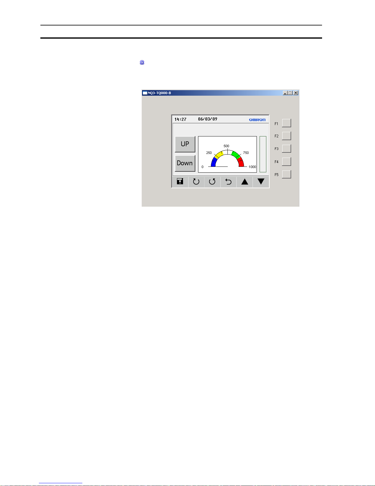
Simulation Section 6-1
62
6-1 Simulation
Click ( ) to start simulation.
With the simulation function you can simulate your project on your Personal
Computer.
Figure 6.1: Simulation
Not supported in simulation is:
• PLC communication (PLC tags are not handled and remain 0)
• Set RTC ( RTC viewing is supported, PC clock is displayed)
• Data logging
• Historical Trends
•Historical alarms
Page 77

Debugging Section 6-2
63
6-2 Debugging
For debugging your NQ-Series you can use an internal program inside the
NQ-Series.
The debugging program (FWHT) allows you to test all HW sections within your
NQ-Series.
To start FWHT, please look at 7-4-1 FHWT.
Page 78

Debugging Section 6-2
64
Page 79

Section
65
SECTION 7
Maintenance
This section describes the maintenance and factory application of the NQSeries.
SECTION 7
Maintenance 65
7-1 Erasing keys.....................................................................................66
7-2 Touch screen calibration ..................................................................67
7-3 Troubleshooting................................................................................ 68
7-4 NQ-Series diagnostics...................................................................... 69
Page 80

Erasing keys Section 7-1
66
7-1 Erasing keys
If necessary, It is possible to erase an application or firmware in the NQSeries. The corners of the touch screen are used for erasing.
Figure 7.1: Erasing keys
1 Erase firmware
2 Erase application
3Confirm
4 Starting FWHT and system set-up
To erase an application proceed as follows.
• Press the top right corner of the touch screen for 2 seconds during poweron.
• The following message is displayed: Application Erase Mode... Press at
Bottom Right corner to confirm. Press the bottom right button to confirm.
• After erasing the program the following message is displayed: No setup
loaded. Download application.
To erase the firmware proceed as follows.
• Press the top left corner of the touch screen for 2 seconds during poweron.
• The following message is displayed: Firmware Erase Mode... Press at
Bottom Right corner to confirm. Press the bottom right button to confirm.
• After erasing the firmware the following message is displayed: No
firmware.... Download firmware.
If the NQ-Series does not function correctly, erase the application and
download a demo program. If the NQ-Series functions correctly, it is possible
the previous application was incorrect.
Page 81

Touch screen calibration Section 7-2
67
7-2 Touch screen calibration
The touch screen is already calibrated. The calibration data is stored in the
flash memory of the NQ-Series. Touch screen calibration is necessary if the
user encounters the following problems:
• Any press inside a defined object boundary does not result in the expected
action.
• An undefined area performs a task of some other defined object.
To calibrate the touch screen proceed as follows.
For accurate calibration use a stylus or wooden pencil.
• Press the centre of the touch screen for more than 2 seconds during
power-up.
• A cross is displayed at the bottom in the left corner. This cross remains on
the touch screen for approximately 4 seconds. If the centre of the cross is
not pressed at this moment, the NQ-Series resumes to normal operation.
Touch the centre of the cross with a pointed object (stylus). Keep pressing
until the NQ-Series reports valid point.
• The next screen is displayed with a cross at the top right corner of the
touch screen. This cross remains on the touch screen for approximately 4
seconds. If the centre of the cross is not pressed at this moment, the NQSeries resumes to normal operation. Touch the centre of the cross with a
pointed object (stylus). Keep pressing until the NQ-Series reports valid
point.
• A successfull calibration always results in a message Calibration
completed....restarting!!! on screen.
Page 82

Troubleshooting Section 7-3
68
7-3 Troubleshooting
Problems and errors are shown in two ways:
• With blue Run LED
• With self-diagnostic messages
7-3-1 Run LED
The Run LED on the touch screen is used to show the status, problems, and/
or errors in the NQ-Series.
If the Run LED is on, the NQ-Series is functioning correctly and an application
is downloaded into the NQ-Series. If the Run LED is off and stays off, even
after touching the screen, the power to the NQ-Series is not correct. Check the
cable connections and/or power supply.
/i
Table 7.1: Run LED status
LED Backlight Action Status/Solution
OFF OFF Press the touch screen. The back
light does not come on.
Failure in the power supply.
Check the power supply
and connections.
OFF ON Check the LED bit 36. The LED bit
s36 is turned off.
The LED status bit s36 is
turned off. Turn the LED
status bit s36 on.
ON OFF Press the touch screen. The back
light comes on.
The NQ-Series is in screen
saver mode.
ON ON - The NQ-Series is working
correctly.
ON
(flashing
slow)
ON - The NQ-Series is working
correctly and is
downloading or uploading.
ON
(flashing
fast)
ON - The NQ-Series is working
correctly and can not
establish a connection to
PLC.
Page 83

NQ-Series diagnostics Section 7-4
69
7-4 NQ-Series diagnostics
The NQ-Series’ firmware contains a special application to test the NQ-Series’
functions and to set the NQ-Series.
The following tools can be used for standalone NQ-Series diagnostic.
Figure 7.2:Loopback connector RS-232/RS-485/RS-422 for testing the serial ports
To access the special application proceed as follows.
1 Download a firmware and an application in the the NQ-Series. (This can be
an empty project.)
2 Press (5 seconds) lower left corner of touch screen during power up of the
NQ-Series. Wait for approximately 5 seconds until the following screen is
displayed.
Figure 7.3: Mode selection menu
3 Choose the application FHWT or System Setup.
4Press Exit to exit the factory application.
Page 84

NQ-Series diagnostics Section 7-4
70
7-4-1 FHWT
The FHWT (Hardware Test) mode is used to test the HW of the NQ-Series.
Examples are LCD test, Function key test, Communication port test, etc.
Figure 7.4: FHWT page 1
Figure 7.5: FHWT page 2
/i
Page 85

NQ-Series diagnostics Section 7-4
71
Table 7.2: FHWT mode tests
Pressing the above buttons on screen will start specific tests as indicated on
the buttons. If needed follow the instruction shown on screen.
Test Description
LCD To test the LCD.
Touch Screen To test the touch screen.
Flash To test the flash.
SRAM To test the SRAM.
EEPROM To test the EEPROM.
RTC To test the function of RTC.
Function keys To test Function keys.
Brightness To test the brightness of the screen.
Contrast To test the contrast of the screen (NQ5)
RS-232 Com1 To test the RS-232 on Com1.
RS-485 Com1 To test the RS-485 on Com1.
RS-232 Com2 To test the RS-232 on Com2 (NQ5).
USB To test the USB ports.
Expansion Port Reserved.
Buzzer To test the beeper.
Save Result Reserved.
Display Result Reserved.
Send Result to PL Reserved.
Page 86
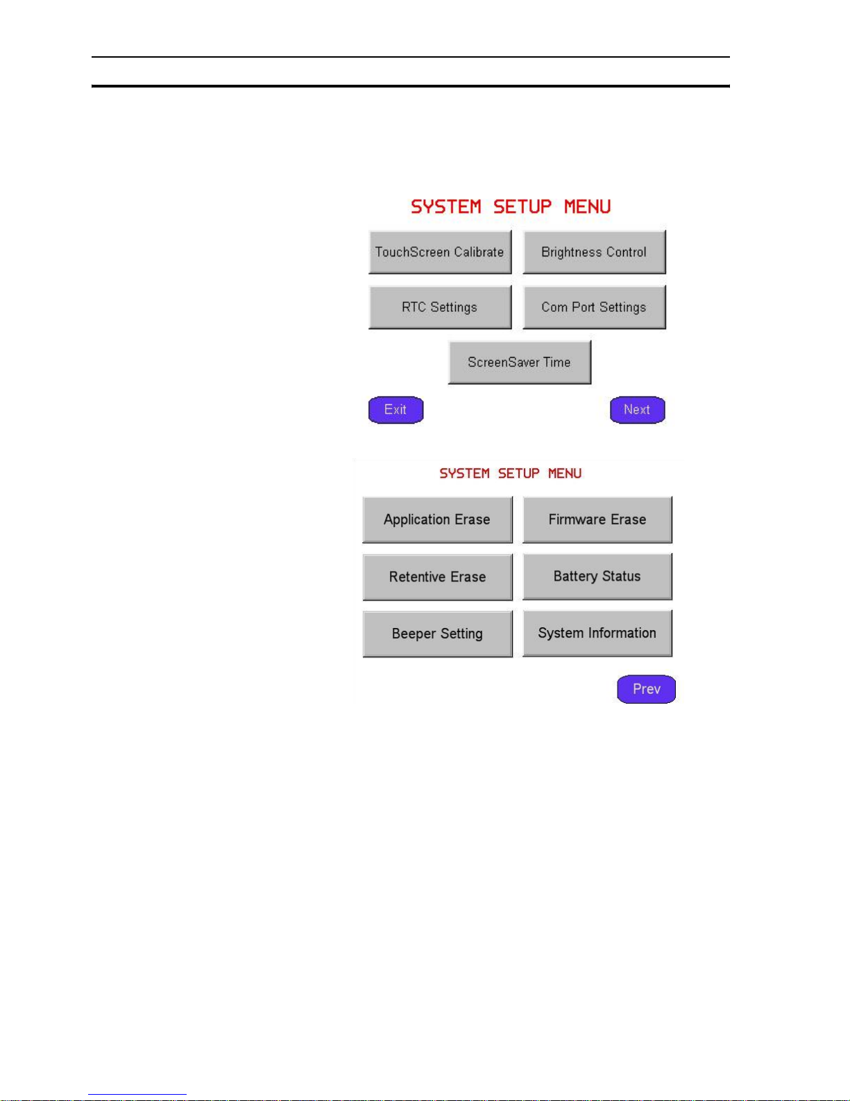
NQ-Series diagnostics Section 7-4
72
7-4-2 System set-up
System set-up menu can be used to set the NQ-Series. In this special
application you can quickly set the RTC time, communcation ports, clear the
retentive registers, etc.
Figure 7.6: System set-up menu page 1
Figure 7.7: System set-up menu page 2
/i
Page 87

NQ-Series diagnostics Section 7-4
73
Table 7.3: System set-up settings
Pressing the buttons on one of the 2 set-up screens will take you to the
specific set-up procedures for the specific settings.
Setting Description
TouchScreen Calibrate To calibrate the touch screen. Refer also to 7-2 Touch
screen calibration.
Brightness Control To set the brightness of the screen.
Contrast Control To set the constrast of the screen (NQ5)
RTC Settings To set the RTC.
Com Port Settings To set the com port.
ScreenSaver Time To set the screensaver time.
Application Erase To erase the application.
Note that if you perform this
action you can not continue with NQ-Series diagnostics.
Firmware Erase To erase the firmware. Note that if you perform this
action you can not continue with NQ-Series diagnostics.
Beeper Setting To set the beeper.
Battery Status To view the battery status.
Clear retentive registers To clear all retentive registers.
System Information To view the system information.
Page 88

NQ-Series diagnostics Section 7-4
74
Page 89

75
Appendix A
A-1 OMRON to NQ-Series configurations
A-1-1 NQ with OMRON Host Link Driver to OMRON CP1L PLC
To perform a successful communication proceed as follows.
1 Create a new project in NQ-Designer.
2 Add a Hostlink Node and settings as below and click Add...
3 Set all data as shown in the screenshot.
4 Create PLC tag with address DM0000.
5Add a Numerical Data Entry object with tag address DM0000 to screen1.
6 Download the application and firmware to the NQ-Series.
7 Open CX-Programmer.
8 Create a new project.
9 Select CP1L and click OK.
10 Double-click Settings in the project panel.
11 C l i ck Serial Port 1 tab.
Page 90

76
12 Set all data as shown in the screenshot.
13 Download the application into the PLC.
14 Click Windows in View menu and select Watch.
15 Enter D0 in the first line in the Watch window.
16 Change Channel type to unit.
17 Connect the cable to the NQ-Series and PLC. Ensure the label on the cable corresponds with the NQ-Series
and PLC (cable connectors are both male). Refer to A-2-2 NQ to PLC (NQCN222 / NQCN521).
18 Check the blue LED. If the blue LED is steady on, a correct connection has been established.
19 Enter 345 on the NQ-Series screen. If the connection has been correctly established the same value is
shown in the Watch window of CX-Programmer.
Note
The following messages are displayed on the NQ-Series’ screen if problems occur:
• !!! no connection
• ??? connection established, address unknown
Page 91

77
A-1-2 NQ with OMRON NT Link to OMRON CP1L PLC
To perform a successful communication proceed as follows.
1 Create a new project in NQ-Designer.
2 Add a NTlink Node and settings as below and click Add...
3 Set all data as shown in the screenshot.
4 Create PLC tag with address DM0000.
5Add a Numerical Data Entry object with tag address DM0000 to screen1.
6 Download the application and firmware to the NQ-Series.
7 Open CX-Programmer.
8 Create a new project.
9 Select CP1L and click OK.
10 Double-click Settings in the project panel.
11 C l i ck Serial Port 1 tab.
Page 92

78
12 Set all data as shown in the screenshot.
13 Download the application into the PLC.
14 Click Windows in View menu and select Watch.
15 Enter D0 in the first line in the Watch window.
16 Change Datatype to Uint
17 Connect the cable to the NQ-Series and PLC. Ensure the label on the cable corresponds with the NQ-Series
and PLC (cable connectors are both male). Refer to A-2-2 NQ to PLC (NQCN222 / NQCN521).
18 Check the blue LED. If the blue LED is steady on, a correct connection has been established.
19 Enter 89 in the NQ-Series’ screen. If the connection has been correctly established the same value is shown
in the Watch window of CX-Programmer.
Note
The following messages are displayed on the NQ-Series’ screen if problems occur:
• !!! no connection
• ??? connection established, address unknown
Page 93

79
A-1-3 NQ to OMRON Memobus inverter
To perform a successful communication between NQ-Series combined with OMRON Memobus inverter
proceed as follows. The example shown is applicable for V1000. The addresses and parameter settings can
vary depending on the choice of the Memobus inverter (not V1000).
1 Create a new project in NQ-Designer.
2 Right-click the Nodes folder and click Add...
3 Set all data as shown in the screenshot.
4 Create a tag with address HR401061
5 Add a display data numeric object with tag address HR401061 on screen1
6 Download the application and firmware to the NQ-Series.
7 Press down button on the inverter until PAr is shown on the inverter’s display.
8 Press enter.
9 Set the following parameters:
• B1-01=2
• H5-01 = 1 (node 1)
• H5-02 = 3 (9600 bps)
• H5-03 = 1 (even parity)
• Stop bit and Data Length are fixed as 1 and 8 respectively (refer to manual).
• H5-07 = 1 (RS-422 connection).
10 Switch off the inverter.
11 Create a cable. Refer to A-2-4 NQ to inverter (V1000, RS-422 connection)
.
12 Connect the cable to the NQ-Series and inverter.
13 Switch on the inverter.
14 If the connection has been correctly established the node number shown on the NQ-Series.
Page 94

80
Note
• H5-07 = 0 (RS-485 connection): Create the applicable cable. Refer to (V1000 RS-485 connection) A-2-5.
• NQ-Series establishes a connection to the inverter by exchanging a default address HR400001. If this
address is not available in the used inverter, the connection will not be established. To establish the
connection proceed as follows.
1 Click in the Nodes folder and right-click the Node1 inverter.
2Click Edit.
3Click PLC Specific Setting.
4
5 Change Default communication register address to an available address in the inverter.
6Click OK.
7 Download the application to the NQ-Series.
• The following messages are displayed on the NQ-Series’ screen if problems occur:
• !!! no connection
• ??? connection established, address unknown
Page 95

81
A-1-4 NQ to CelciuX° (EJ1N) Temperature Controller (ModBus
RTU)
To perform a successful communication proceed as follows. The example shown is applicable for EJ1.
1 Create a new project in NQ-Designer.
2 Right-click the Nodes folder and click Add...
3 Set all data as shown in the screenshot.
4 Create a tag with address Holding register 513. (400513).
5Add a Numerical Data Entry object with tag address 400513 on screen1
6 Download the application and firmware to the NQ-Series.
7 Set Unit number to 1 on EJ1( rotary switch).
8 Set the following dipswitches on TC module:
• SW2 dipswitch 3 to ON
• SW2 dipswitch 4 to OFF
• SW2 dipswitch 5 to OFF
9 Switch on the EJ1 temperature controller.
10 Create a cable. Refer to A-2-6 NQ to CelciuX° (EJ1N) temperature controllers (RS-485 connection).
11 Connect the cable to the NQ-Series and EJ1C-EDUA-NFLK
12 Displayed on your screen will be now the “ Channel 1 Process Value)
13 Correct data can be monitored by connecting CX-Thermo to your EJ1.
Note
The following messages are displayed on the NQ-Series’ screen if problems occur:
• !!! no connection
• ??? connection established, address unknown
Page 96

82
A-2 OMRON communication cables
A-2-1 Cable references
The following tables provide an overview of the available cables from OMRON. The table shows which PLC can
be used with the cable. OMRON provides three types of cables:
• Cables for PLCs with serial ports (DSUB9 to DSUB9)
• Cables for PLCs for mini-peripheral ports (DSUB9 to mini-peripheral)
• Programming cables
/i
Table A.1: DSUB9 to DSUB9
/i
Table A.2: Mini-peripheral to DSUB9
/i
Table A.3: Programming cables
PLC Cable Note
CP1L
CP1H
CJ1
CS1
CPM2*
CQM1H
NQ-CN222
NQ-CN521
2 meter cable
5 meter cable
PLC Cable Note
CJ1
CS1
CPM2C
CQM1H
NQ-CN221 2 meter cable
Cable Note
CP1WCN221 USB cable (1.8 meter)
NT2SCN002 Serial cable (2 meter)
Page 97

83
A-2-2 NQ to PLC (NQCN222 / NQCN521)
/i
DB9 MALE PINOUTS (PLC) DB9 MALE PINOUTS (NQ)
Signals Pin number Pin number Signals
11
TXD 2 2 TXD
RXD 3 3 RXD
RTS 4 4
CTS 5 5 SG
66
77
88
SG 9 9
Shield wire to DB9 body Shield wire to DB9 body
Page 98

84
A-2-3 NQ to PC
/i
DB9 FEMALE PINOUTS (PC) DB9 MALE PINOUTS (NQ)
Signals Pin number Pin number Signals
11
RXD 2 2 TXD
TXD 3 3 RXD
44
SG 5 5 SG
66
77
88
99
Shield wire to DB9 body Shield wire to DB9 body
Page 99

85
A-2-4 NQ to inverter (V1000, RS-422 connection)
/i
FREE END DB9 MALE PINOUTS (NQ)
Signals Pin number Signals
(R+) RX+ 1 TX+
(R-) RX- 2
S+ (TX+) 3
S- (TX-) 4 RX+
IG 5 SG
6
7
8TX-
9RX-
shield wire to ground shield wire to body
Page 100
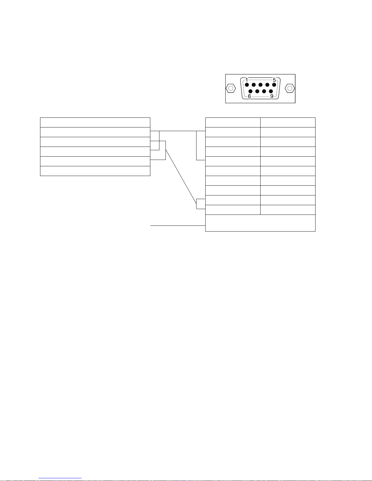
86
A-2-5 NQ to inverter (V1000, RS-485 connection)
/i
FREE END DB9 MALE PINOUTS (NQ)
Signals Pin number Signals
(R+) RX+ 1 TX+
(R-) RX- 2
S+ (TX+) 3
S- (TX-) 4 RX+
IG 5 SG
6
7
8TX-
9RX-
shield wire to ground Shield wire to DB9 body
 Loading...