

Page 1
Machine Automation Controller
NJ-series
Robot Integrated CPU Unit
User’s Manual
NJ501-R500
NJ501-R400
NJ501-R300
CPU Unit
O037-E1-01
Page 2

NOTE
All rights reserved. No part of this publication may be reproduced, stored in a retrieval system, or transmitted, in
any form, or by any means, mechanical, electronic, photocopying, recording, or otherwise, without the prior
written permission of OMRON.
No patent liability is assumed with respect to the use of the information contained herein. Moreover, because
OMRON is constantly striving to improve its high-quality products, the information contained in this manual is
subject to change without notice. Every precaution has been taken in the preparation of this manual. Nevertheless, OMRON assumes no responsibility for errors or omissions. Neither is any liability assumed for damages
resulting from the use of the information contained in this publication.
Trademarks
• Sysmac and SYSMAC are trademarks or registered trademarks of OMRON Corporation in Japan and other
countries for OMRON factory automation products.
• Microsoft, Windows, Excel, and Visual Basic are either registered trademarks or trademarks of Microsoft Corporation in the United States and other countries.
• EtherCAT® is registered trademark and patented technology, licensed by Beckhoff Automation GmbH, Germany.
• ODVA, CIP, CompoNet, DeviceNet, and EtherNet/IP are trademarks of ODVA.
• The SD and SDHC logos are trademarks of SD-3C, LLC.
Other company names and product names in this document are the trademarks or registered trademarks of their
respective companies.
Copyrights
• Microsoft product screen shots reprinted with permission from Microsoft Corporation.
• This product incorporates certain third party software. The license and copyright information associated with this
software is available at http://www.fa.omron.co.jp/nj_info_e/.
Page 3

Introduction
Thank you for purchasing an NJ-series Robot Integrated CPU Unit.
This manual contains information that is necessary to use the robot control function of the NJ-series
CPU Unit. Please read this manual and make sure you understand the functionality and performance
of the NJ-series CPU Unit before you attempt to use it in a control system.
Keep this manual in a safe place where it will be available for reference during operation.
This manual describes the functions added to the NJ501-R£££ CPU Unit.
Refer to the NJ/NX-series CPU Unit Software User’s Manual (Cat. No. W501) for information on the
common functions for the NJ501-££££ CPU Unit.
Intended Audience
This manual is intended for the following personnel, who must also have knowledge of electrical sys-
tems (an electrical engineer or the equivalent).
Personnel in charge of introducing F
•
• Personnel in charge of designing FA systems.
• Personnel in charge of installing and maintaining FA systems.
• Personnel in charge of managing FA systems and facilities.
Also, this manual is intended for the personnel, who understand the following contents.
• Personnel who understand the programming language specifications in international standard IEC
61131-3 or Japanese standard JIS B 3503, for programming.
• Personnel in charge of working with a robot and well knowing how to handle the robot.
Introduction
A systems.
Applicable Products
This manual covers the following products.
NJ-series Robot Integrated CPU Unit
•
NJ501-R500
NJ501-R400
NJ501-R300
NJ-series Robot Integrated CPU Unit User's Manual (O037)
1
Page 4
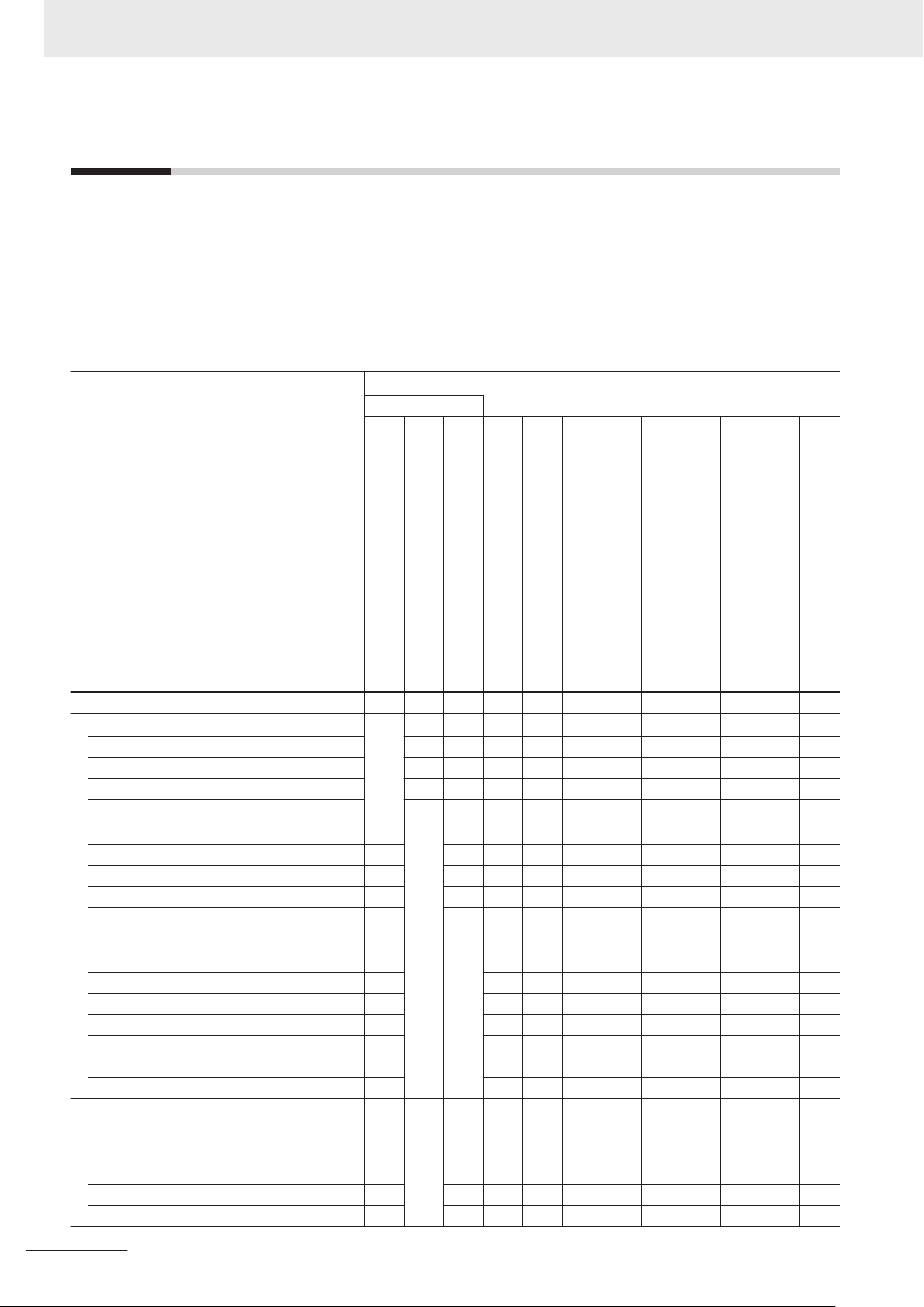
Relevant Manuals
Relevant Manuals
The following table provides the relevant manuals for the NJ-series CPU Units. Read all of the man-
uals that are relevant to your system configuration and application before you use the NJ-series CPU
Unit.
Most operations are performed from the Sysmac Studio Automation Software. Refer to the Sysmac
Studio Version 1 Operation Manual (Cat. No. W504) and the Sysmac Studio Robot Integrated System
Building Function with Robot Integrated CPU Unit Operation Manual (Cat. No. W595) for information
on the Sysmac Studio.
Basic information
NJ-series CPU Unit
Hardware User’s Manual
NJ/NX-series CPU Unit
Software User
Instructions Reference Manual
NJ/NX-series
NJ/NX-series CPU Unit
Motion Control User
NJ/NX-series
Motion Control Instructions Reference Manual
Manual
NJ/NX-series CPU Unit
Built-in EtherNet/IP Port User’
NJ/NX-series CPU Unit
Built-in EtherCA
NJ-series Robot Integrated CPU Unit
User
eV+3 User’s Manual
eV+3 Keyword Reference Manual
NJ-series NJ Robotics CPU Unit
User
NJ/NX-series
Troubleshooting Manual
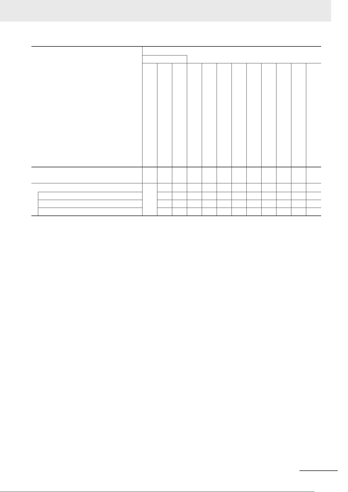
Purpose of use
Introduction to NJ-series Controllers
Setting devices and hardware
Using motion control
Using EtherCAT
Using EtherNet/IP
Using robot control for OMRON robots
Software settings
Using motion control
Using EtherCAT
Using EtherNet/IP
Using robot control for OMRON robots
Using robot control with NJ Robotics function
Writing the user program
Using motion control
Using EtherCAT
Using EtherNet/IP
Using robot control for OMRON robots
Using robot control with NJ Robotics function
Programming error processing
Testing operation and debugging
Using motion control
Using EtherCAT
Using EtherNet/IP
Using robot control for OMRON robots
Using robot control with NJ Robotics function
¡
¡
’
s Manual
¡
¡ ¡
¡
’s Manual
¡
¡
¡ ¡
¡
T Port User
’s Manual
s Manual
¡
¡
¡
¡
¡
¡
¡
¡
’
s Manual
¡
¡ ¡ ¡
¡ ¡ ¡
¡ ¡ ¡ ¡
¡ ¡ ¡
’
s Manual
¡
¡
¡
2
NJ-series Robot Integrated CPU Unit User's Manual (O037)
Page 5
Purpose of use
Basic information
NJ-series CPU Unit
Hardware User’s Manual
NJ/NX-series CPU Unit
Software User
Instructions Reference Manual
’
s Manual
NJ/NX-series
NJ/NX-series CPU Unit
Motion Control User
’
s Manual
NJ/NX-series
Motion Control Instructions Reference Manual
Relevant Manuals
Manual
NJ/NX-series CPU Unit
Built-in EtherCA
T Port User
’s Manual
NJ/NX-series CPU Unit
Built-in EtherNet/IP Port User
’
s Manual
NJ-series Robot Integrated CPU Unit
User’
s Manual
eV+3 User’s Manual
eV+3 Keyword Reference Manual
NJ-series NJ Robotics CPU Unit
User
’
s Manual
NJ/NX-series
T
roubleshooting Manual
Learning about error management functions and
corrections
Maintenance
*1. Refer to the NJ/NX-series Troubleshooting Manual (Cat. No. W503) for the error management concepts and the error items. However
*1
Using motion control
Using EtherCAT
Using EtherNet/IP
refer to the manuals that are indicated with triangles for details on errors corresponding to the products with the manuals that are indicated with triangles.
¡
¡
¡
r r r r ¡
¡
,
NJ-series Robot Integrated CPU Unit User's Manual (O037)
3
Page 6
4-9
4
Installation and Wiring
NJ-series CPU Unit Hardware User’s Manual (W500)
s
t
i
n
U
gnitn
u
oM
3-4
4
s
t
ne
no
p
m
o
C
rel
l
o
r
t
n
oC
g
n
i
tc
e
n
noC
1
-
3-
4
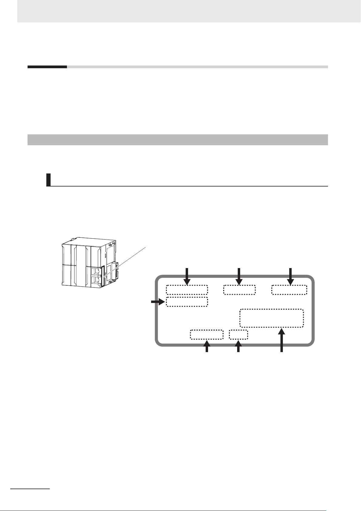
4-3 Mounting Units
The Units that make up an NJ-series Controller can be connected simply by pressing the Units together
and locking the sliders by moving them toward the back of the Units. The End Cover is connected in the
same way to the Unit on the far right side of the Controller.
1 Join the Units so that the connectors fit exactly.
2 The yellow sliders at the top and bottom of each Unit lock the Units together. Move the sliders
toward the back of the Units as shown below until they click into place.
Precautions for Correct UsePrecautions for Correct Use
4-3-1 Connecting Controller Components
Connector
Hook
Hook holes
Slider
Lock
Release
Move the sliders toward the back
until they lock into place.
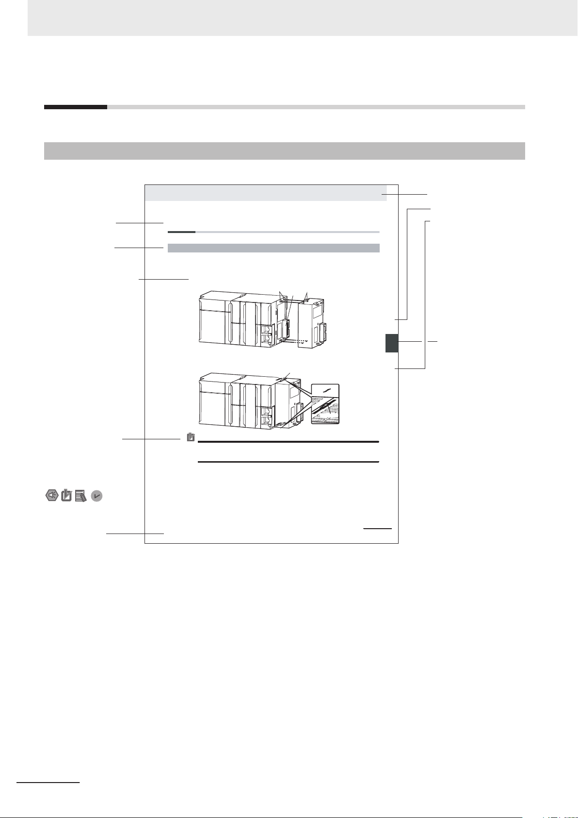
Level 1 heading
Level 2 heading
Level 3 heading
Level 2 heading
A step in a procedure
Manual name
Special information
Level 3 heading
Page tab
Gives the current
headings.
Indicates a procedure.
Icons indicate
precautions, additional
information, or reference
information.
Gives the number
of the main section.
This illustration is provided only as a sample. It may not literally appear in this manual.
Th
e sliders on the tops and bottoms of the Power Supply Unit, CPU Unit, I/O Units, Special I/O
Units, and CPU Bus Units must be completely locked (until they click into place) after connecting
the adjacent Unit connectors.
Manual Structure
Manual Structure
Page Structure
The following page structure is used in this manual.
4
NJ-series Robot Integrated CPU Unit User's Manual (O037)
Page 7

Special Information
Special information in this manual is classified as follows:
Precautions for Safe Use
Precautions on what to do and what not to do to ensure safe usage of the product.
Precautions for Correct Use
Precautions on what to do and what not to do to ensure proper operation and performance.
Additional Information
Additional information to read as required.
This information is provided to increase understanding or make operation easier.
Manual Structure
Version Information
Information on dif
and for dif
ferent versions of the Sysmac Studio is given.
ferences in specifications and functionality for Controller with different unit versions
Precaution on Terminology
In this manual, "download" refers to transferring data from the Sysmac Studio to the physical Control-
ler and "upload
For the Sysmac Studio, "synchronization
"synchronize" means to automatically compare the data for the Sysmac Studio on the computer with
the data in the physical Controller and transfer the data in the direction that is specified by the user.
" refers to transferring data from the physical Controller to the Sysmac Studio.
" is used to both "upload" and "download" data. Here,
NJ-series Robot Integrated CPU Unit User's Manual (O037)
5
Page 8

Manual Structure
6
NJ-series Robot Integrated CPU Unit User's Manual (O037)
Page 9
Sections in this Manual
1
10
2
11
3
4
5
6
7
8
9
1
10
2
11
3 A
I
4
5
6
7
8
9
Introduction to Robot
Integrated CPU Unit
Robot Control System
Configuration and Functions
Robot Control Parameters
Program Design of
Robot Control
A
Robot Control Instructions
Robot Control Function
Common Command Instructions
Variables and Instructions
Robot Command Instructions
13
System Control
Instructions
Troubleshooting
Appendices
I
Index
Sections in this Manual
NJ-series Robot Integrated CPU Unit User's Manual (O037)
7
Page 10

CONTENTS
CONTENTS
Introduction .............................................................................................................. 1
Intended Audience...........................................................................................................................................1
Applicable Products
Relevant Manuals..................................................................................................... 2
Manual Structure...................................................................................................... 4
Page Structure.................................................................................................................................................4
Special Information .......................................................................................................................................... 5
Precaution on Terminology ..............................................................................................................................5
Sections in this Manual ........................................................................................... 7
Terms and Conditions Agreement........................................................................ 13
Warranty, Limitations of Liability ....................................................................................................................13
Application Considerations ............................................................................................................................14
Disclaimers ....................................................................................................................................................14
.........................................................................................................................................1
Safety Precautions................................................................................................. 16
Definition of Precautionary Information.......................................................................................................... 16
Symbols ......................................................................................................................................................... 16
WARNING......................................................................................................................................................17
Cautions......................................................................................................................................................... 17
Precautions for Safe Use ...................................................................................... 19
Precautions for Correct Use ................................................................................. 20
Regulations and Standards .................................................................................. 21
Versions.................................................................................................................. 22
Checking Versions.........................................................................................................................................22
Related Manuals..................................................................................................... 24
Terminology............................................................................................................ 27
Revision History..................................................................................................... 28
Section 1 Introduction to Robot Integrated CPU Unit
1-1 Features ..................................................................................................................................1-2
1-2 System Configuration
1-3 Specifications.........................................................................................................................1-6
1-3-1 General Specifications ................................................................................................................1-6
1-3-2 Performance Specifications ........................................................................................................1-6
1-3-3 Function Specifications ...............................................................................................................1-6
1-3-4 V+ Program Specifications..........................................................................................................1-8
1-4 Basic Procedure of Operation ..............................................................................................1-9
8
............................................................................................................1-4
NJ-series Robot Integrated CPU Unit User's Manual (O037)
Page 11

CONTENTS
Section 2 Robot Control System Configuration and Functions
2-1 Internal Configuration for the Robot Integrated CPU Unit.................................................2-2
2-2 Relationship between
2-3 Relationship between Robot Integrated CPU Unit and IPC Application Controller ........2-6
2-4 System-defined Variables for Robot Control ......................................................................2-8
2-4-1 Overview of System-defined Variables for Robot Control ...........................................................2-8
2-4-2 System of System-defined Variables for Robot Control ..............................................................2-8
2-4-3 Attributes of System-defined Variables for Robot Control ......................................................... 2-11
2-5 Tasks ..................................................................................................................................... 2-12
2-5-1 Tasks and Services for Robot Integrated CPU Unit ..................................................................2-12
2-5-2 Basic Operation of Tasks ..........................................................................................................2-12
2-5-3 Relationship between V+ Task and I/O Refreshing...................................................................2-14
2-6 EtherCAT Communications and Robot Control................................................................2-15
2-7 SD Memory Card Operations .............................................................................................. 2-17
2-7-1 Included SD Memory Card Functions .......................................................................................2-18
2-7-2 Exclusive Control of File Access in the SD Memory Card ........................................................2-20
2-8 Memory Management ..........................................................................................................2-22
2-8-1 Data and File Locations ............................................................................................................2-22
2-8-2 Clear All Memory.......................................................................................................................2-22
2-9 Backup and Restore Operations ........................................................................................2-24
2-9-1 Backup and Restore Operations for Robot Integrated CPU Unit ..............................................2-24
2-9-2 Backup and Restore Operations for OMRON Robot ................................................................2-27
2-10 Security.................................................................................................................................2-29
2-10-1 Robot System Operation Authority............................................................................................2-29
2-10-2 CPU Unit Write Protection.........................................................................................................2-29
Robot Integrated CPU Unit and Robot...........................................2-3
Section 3 Robot Control Parameters
3-1 Introduction to Robot Control Parameters..........................................................................3-2
3-1-1 Data Flow for Robot Control Parameters
3-1-2 Relationship between V+ Program and Robot Control Parameters............................................3-3
....................................................................................3-2
3-2 Robot Common Parameters .................................................................................................3-4
3-2-1 Robot Common Parameters .......................................................................................................3-4
3-2-2 I/O Control Settings.....................................................................................................................3-4
3-3 Robot Setting Parameters.....................................................................................................3-7
3-3-1 Robot Setting Parameters...........................................................................................................3-7
3-3-2 Robot Basic Settings...................................................................................................................3-7
Section 4 Program Design of Robot Control
4-1 Introduction ............................................................................................................................4-2
4-2 Sequence Control Program ..................................................................................................4-3
4-2-1 Robot Control Instructions...........................................................................................................4-3
4-2-2 Timing Charts for Robot Control Instructions ..............................................................................4-3
4-2-3 System-defined Variables for Robot Control ...............................................................................4-6
4-2-4 Execution Control for V+ Program ..............................................................................................4-6
4-2-5 Shared Variables with V+ Program .............................................................................................4-7
4-2-6 Using Shared Variables with V+ Programs ...............................................................................4-11
4-3 V+ Program...........................................................................................................................4-14
4-3-1 Overview of V+ Programs .........................................................................................................4-14
4-3-2 Control of V+ Tasks...................................................................................................................4-14
4-3-3 I/O Control Settings for V+ Program .........................................................................................4-14
NJ-series Robot Integrated CPU Unit User's Manual (O037)
9
Page 12

CONTENTS
4-4 Debugging Program ............................................................................................................4-16
4-4-1 Of
4-4-2 Transferring Settings and Programs .........................................................................................4-17
4-4-3 Online Debugging .....................................................................................................................4-17
fline Debugging......................................................................................................................4-16
4-5 States and State Transition.................................................................................................4-19
4-5-1 States of the Robot Integrated CPU Unit ..................................................................................4-19
4-5-2 States of the OMRON Robots...................................................................................................4-20
4-5-3 Changing the Operating Mode ..................................................................................................4-23
4-5-4 Operation of Events ..................................................................................................................4-24
Section 5 Robot Control Function
5-1 Robot Control Common Function ........................................................................................ 5-2
5-2 Latching
5-2-1 Robot Position Latching ..............................................................................................................5-5
5-2-2 Robot Built-in Encoder Latching..................................................................................................5-6
5-3 Coordinate System Integration with NJ Robotics Function .............................................5-8
5-4 Changing Recipe..................................................................................................................5-10
..................................................................................................................................5-5
Section 6 Robot Control Instructions
6-1 Overview of Robot Control Instructions..............................................................................6-2
6-1-1 T
6-1-2 Execution and Status of Robot Control Instructions....................................................................6-2
6-1-3 Error Processing .........................................................................................................................6-2
6-1-4 Changing Input Variables during Execution of Robot Control Instructions (Instruction
6-1-5 Multi-execution of Instructions with BufferMode..........................................................................6-3
ypes of Robot Control Instructions ............................................................................................6-2
Re-execution)..............................................................................................................................6-3
6-2 Basic Understanding of Robot Control Instructions..........................................................6-6
6-2-1 Names of Robot Control Instructions ..........................................................................................6-6
6-2-2 Languages of Robot Control Instructions ...................................................................................6-6
6-2-3 Locations of Robot Control Instructions ......................................................................................6-6
6-2-4 OMRON Robot Specification Method in Sequence Control Program .......................................6-10
6-2-5 Multi-execution of Robot Control Instructions ...........................................................................6-10
6-2-6 Executing Robot Control Instructions to Uncreated Robots...................................................... 6-11
Section 7 Variables and Instructions
7-1 System-defined variables for Robot Control.......................................................................7-2
7-1-1 Robot Control Common Variable.................................................................................................7-2
7-1-2 Robot Variables ...........................................................................................................................7-3
7-1-3 Robot I/O Variables .....................................................................................................................7-7
7-2 Instructions ............................................................................................................................7-9
7-2-1 Common Commands ..................................................................................................................7-9
7-2-2 Robot Commands .......................................................................................................................7-9
7-2-3 System Control Instructions ......................................................................................................7-10
Section 8 Common Command Instructions
RC_ExecVpPrgTask ......................................................................................................................... 8-2
Variables
Function ........................................................................................................................................................8-3
RC_AbortVpPrgTask........................................................................................................................8-6
Variables.......................................................................................................................................................8-6
10
.......................................................................................................................................................8-2
NJ-series Robot Integrated CPU Unit User's Manual (O037)
Page 13

Function ........................................................................................................................................................8-7
RC_GetVpPrgTaskStatus
Variables .......................................................................................................................................................8-8
Function ........................................................................................................................................................8-9
................................................................................................................8-8
RC_ConvertCoordSystem ............................................................................................................. 8-11
Variables .....................................................................................................................................................8-11
Function ......................................................................................................................................................8-12
Section 9 Robot Command Instructions
RC_EnablePower .............................................................................................................................9-2
Variables
Function ........................................................................................................................................................9-3
RC_DisablePower ............................................................................................................................9-5
Variables.......................................................................................................................................................9-5
Function ........................................................................................................................................................9-6
RC_Calibrate.....................................................................................................................................9-8
Variables.......................................................................................................................................................9-8
Function ........................................................................................................................................................9-9
RC_AttachRobot ............................................................................................................................9-10
Variables.....................................................................................................................................................9-10
Function ...................................................................................................................................................... 9-11
Precautions for Correct Use .......................................................................................................................9-12
RC_DetachRobot............................................................................................................................9-13
Variables.....................................................................................................................................................9-13
Function ......................................................................................................................................................9-14
RC_SetToolTransform ...................................................................................................................9-15
Variables.....................................................................................................................................................9-15
Function ......................................................................................................................................................9-16
Precautions for Correct Use .......................................................................................................................9-18
RC_MoveDirect...............................................................................................................................9-20
Variables.....................................................................................................................................................9-20
Function ......................................................................................................................................................9-23
RC_MoveLinear ..............................................................................................................................9-27
Variables.....................................................................................................................................................9-27
Function ......................................................................................................................................................9-30
RC_Stop ..........................................................................................................................................9-33
Variables.....................................................................................................................................................9-33
Function ......................................................................................................................................................9-34
RC_Reset ........................................................................................................................................9-36
Variables.....................................................................................................................................................9-36
Function ......................................................................................................................................................9-37
.......................................................................................................................................................9-2
CONTENTS
Section 10 System Control Instructions
ResetRCError .................................................................................................................................10-2
Variables
Function ......................................................................................................................................................10-3
GetRCError .....................................................................................................................................10-4
Variables.....................................................................................................................................................10-4
Function ......................................................................................................................................................10-4
NJ-series Robot Integrated CPU Unit User's Manual (O037)
.....................................................................................................................................................10-2
11
Page 14

CONTENTS
Section 11 Troubleshooting
11-1 Errors .................................................................................................................................... 11-2
11-1-1
11-1-2 Error Sources ........................................................................................................................... 11-2
11-1-3 Error Levels...............................................................................................................................11-3
11-1-4 Robot Control Function Module Errors by Source ....................................................................11-3
11-1-5 Errors Related to EtherCAT Communications and EtherCAT Slaves .......................................11-5
11-1-6 OMRON Robot Events .............................................................................................................11-5
11-2 Identifying and Resetting Errors ........................................................................................ 11-7
11-2-1 How to Check for Errors............................................................................................................ 11-7
11-2-2 How to Reset Errors..................................................................................................................11-8
11-3 Error Table ............................................................................................................................ 11-9
11-3-1 How to Read Error Tables ......................................................................................................... 11-9
11-3-2 Error Tables............................................................................................................................... 11-9
11-4 Error Descriptions .............................................................................................................11-21
11-4-1 How to Read Error Descriptions.............................................................................................. 11-21
11-4-2 Error Descriptions ...................................................................................................................11-22
Sources of Errors Related to the Robot Control Function Module ............................................ 11-2
Appendices
A-1 Differences in Functions between Robot Integrated CPU Unit and NJ-series CPU UnitA-2
A-2 Guideline for System Service Execution T
Index
ime Ratio......................................................... A-3
12
NJ-series Robot Integrated CPU Unit User's Manual (O037)
Page 15

Terms and Conditions Agreement
Terms and Conditions Agreement
Warranty, Limitations of Liability
Warranties
Exclusive Warranty
Omron’s exclusive warranty is that the Products will be free from defects in materials and work-
manship for a period of twelve months from the date of sale by Omron (or such other period ex-
pressed in writing by Omron). Omron disclaims all other warranties, express or implied.
Limitations
OMRON MAKES NO WARRANTY OR REPRESENTATION, EXPRESS OR IMPLIED, ABOUT
NON-INFRINGEMENT, MERCHANTABILITY OR FITNESS FOR A PARTICULAR PURPOSE OF
THE PRODUCTS. BUYER ACKNOWLEDGES THAT IT ALONE HAS DETERMINED THAT THE
PRODUCTS WILL SUITABLY MEET THE REQUIREMENTS OF THEIR INTENDED USE.
Omron further disclaims all warranties and responsibility of any type for claims or expenses based
on infringement by the Products or otherwise of any intellectual property right.
Buyer Remedy
Omron’s sole obligation hereunder shall be, at Omron’s election, to (i) replace (in the form originally
shipped with Buyer responsible for labor charges for removal or replacement thereof) the non-com-
plying Product, (ii) repair the non-complying Product, or (iii) repay or credit Buyer an amount equal
to the purchase price of the non-complying Product; provided that in no event shall Omron be re-
sponsible for warranty, repair, indemnity or any other claims or expenses regarding the Products
unless Omron’s analysis confirms that the Products were properly handled, stored, installed and
maintained and not subject to contamination, abuse, misuse or inappropriate modification. Return
of any Products by Buyer must be approved in writing by Omron before shipment. Omron Compa-
nies shall not be liable for the suitability or unsuitability or the results from the use of Products in
combination with any electrical or electronic components, circuits, system assemblies or any other
materials or substances or environments. Any advice, recommendations or information given orally
or in writing, are not to be construed as an amendment or addition to the above warranty.
See http://www.omron.com/global/ or contact your Omron representative for published information.
Limitation on Liability; Etc
OMRON COMPANIES SHALL NOT BE LIABLE FOR SPECIAL, INDIRECT, INCIDENTAL, OR CON-
SEQUENTIAL DAMAGES, LOSS OF PROFITS OR PRODUCTION OR COMMERCIAL LOSS IN ANY
NJ-series Robot Integrated CPU Unit User's Manual (O037)
13
Page 16

Terms and Conditions Agreement
WAY CONNECTED WITH THE PRODUCTS, WHETHER SUCH CLAIM IS BASED IN CONTRACT,
WARRANTY
Further, in no event shall liability of Omron Companies exceed the individual price of the Product on
which liability is asserted.
, NEGLIGENCE OR STRICT LIABILITY.
Application Considerations
Suitability of Use
Omron Companies shall not be responsible for conformity with any standards, codes or regulations
which apply to the combination of the Product in the Buyer’
er’s request, Omron will provide applicable third party certification documents identifying ratings and
limitations of use which apply to the Product. This information by itself is not sufficient for a complete
determination of the suitability of the Product in combination with the end product, machine, system, or
other application or use. Buyer shall be solely responsible for determining appropriateness of the par-
ticular Product with respect to Buyer’s application, product or system. Buyer shall take application re-
sponsibility in all cases.
s application or use of the Product. At Buy-
NEVER USE THE PRODUCT FOR AN APPLICATION INVOLVING SERIOUS RISK TO LIFE OR
PROPERTY OR IN LARGE QUANTITIES WITHOUT ENSURING THAT THE SYSTEM AS A WHOLE
HAS BEEN DESIGNED TO ADDRESS THE RISKS, AND THAT THE OMRON PRODUCT(S) IS
PROPERLY RATED AND INSTALLED FOR THE INTENDED USE WITHIN THE OVERALL EQUIP-
MENT OR SYSTEM.
Programmable Products
Omron Companies shall not be responsible for the user’s programming of a programmable Product, or
any consequence thereof.
Disclaimers
Performance Data
Data presented in Omron Company websites, catalogs and other materials is provided as a guide for
the user in determining suitability and does not constitute a warranty. It may represent the result of
Omron’
formance is subject to the Omron’s Warranty and Limitations of Liability.
s test conditions, and the user must correlate it to actual application requirements. Actual per-
14
Change in Specifications
Product specifications and accessories may be changed at any time based on improvements and oth-
er reasons. It is our practice to change part numbers when published ratings or features are changed,
or when significant construction changes are made. However, some specifications of the Product may
NJ-series Robot Integrated CPU Unit User's Manual (O037)
Page 17

Terms and Conditions Agreement
be changed without any notice. When in doubt, special part numbers may be assigned to fix or estab-
lish key specifications for your application. Please consult with your Omron’s representative at any
time to confirm actual specifications of purchased Product.
Errors and Omissions
Information presented by Omron Companies has been checked and is believed to be accurate; how-
ever, no responsibility is assumed for clerical, typographical or proofreading errors or omissions.
NJ-series Robot Integrated CPU Unit User's Manual (O037)
15
Page 18
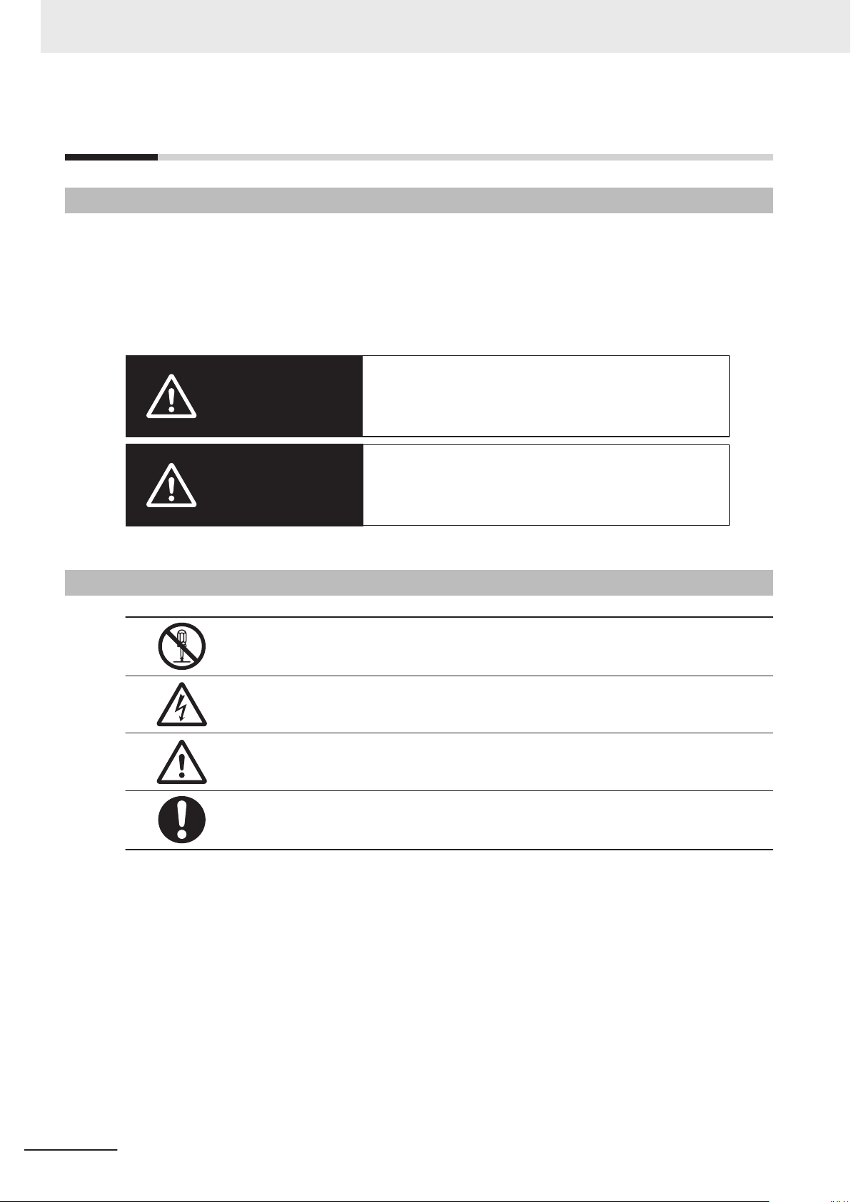
Indicates a potentially hazardous situation which, if
not avoided, could result in death or serious injury.
Additionally, there may be severe property
damage.
Indicates a potentially hazardous situation which, if
not avoided, may result in minor or moderate
injury, or property damage.
WARNING
C
aution
Safety Precautions
Safety Precautions
Definition of Precautionary Information
The following notation is used in this manual to provide precautions required to ensure safe usage of
the NJ-series Robot Integrated CPU Unit.
The safety precautions that are provided are extremely important for safety. Always read and heed the
information provided in all safety precautions.
The following notation is used.
Symbols
The circle and slash symbol indicates operations that you must not do.
The specific operation is shown in the circle and explained in text.
This example indicates that disassembly is prohibited.
The triangle symbol indicates precautions (including warnings).
The specific operation is shown in the triangle and explained in text.
This example indicates a precaution for electric shock.
The triangle symbol indicates precautions (including warnings).
The specific operation is shown in the triangle and explained in text.
This example indicates a general precaution.
The filled circle symbol indicates operations that you must do.
The specific operation is shown in the circle and explained in text.
This example shows a general precaution for something that you must do.
16
NJ-series Robot Integrated CPU Unit User's Manual (O037)
Page 19
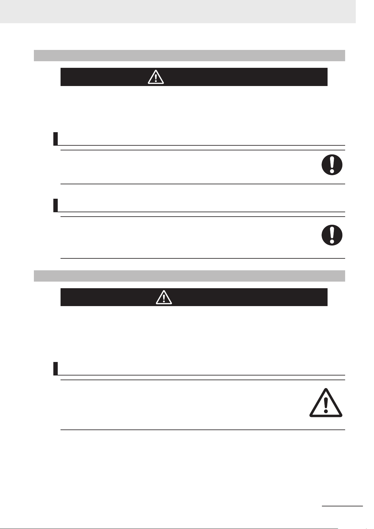
WARNING
WARNING
Caution
Refer to the following manuals for warnings.
• NJ-series CPU Unit Hardware User’
Designing Systems
When you build a robot system including this CPU Unit and OMRON robots, be sure to comply with
laws and regulations relating to the safety of industrial robot application in a country or region where
the robots are used to design and operate the system.
Refer to the Robot Safety Guide (Cat. No. I590) for details.
Safety Precautions
s Manual (Cat. No. W500)
Operation
If you change the operating mode of this CPU Unit from RUN Mode to PROGRAM Mode, the sequence control program stops, but the current V+ program continues. If necessary, monitor the operating mode of the CPU Unit from the V+ program and stop the V+ program.
Always confirm safety when you change the operating mode of the CPU Unit during execution of the
V+ program. If you cannot confirm safety, stop the V+ program and then change the operating mode.
Cautions
Refer to the following manuals for cautions.
• NJ-series CPU Unit Hardware User’
• NJ-series NJ Robotics CPU Unit User's Manual (Cat. No. W539)
Designing Programs
There are different methods to attach a robot from the sequence control program and the V+
program. In addition, when a robot is attached from a program, the robot cannot be attached
from another program without detaching the robot.
If the same OMRON robot is controlled by switching the sequence control program or the V+
program respectively, make sure to detach the robot from the program that the robot is attached,
and then change the control program to attach the robot.
s Manual (Cat. No. W500)
NJ-series Robot Integrated CPU Unit User's Manual (O037)
17
Page 20
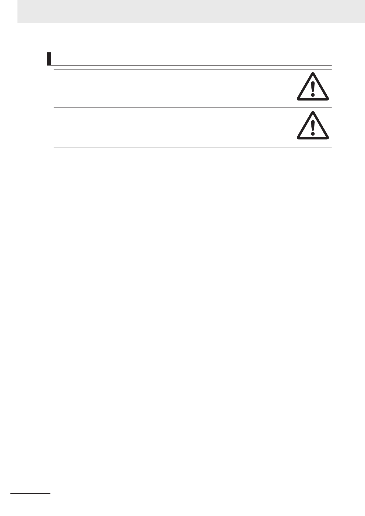
Safety Precautions
Operation
Do not remove the SD Memory Card during operation when you use the robot control function
with this product.
Doing so causes the robot control function to stop due to an error.
The V+ program files and the robot setting files in the SD Memory Card are required for the operation of the Robot Control Function Module. Do not edit or delete the files if you are not sure
that the operation is not affected even when the files are edited and deleted.
Always confirm how the file operations af
SD Memory Card.
fect the control before you perform file operations in the
18
NJ-series Robot Integrated CPU Unit User's Manual (O037)
Page 21

Precautions for Safe Use
Refer to the following manuals for precautions for safe use.
• NJ-series CPU Unit Hardware User’s Manual (Cat. No. W500)
Motion Control
• The coordinate system used by the Robot Control Function Module have different specifications
from the coordinate system used by the NJ Robotics function.
If you use both functions simultaneously, use the RC_ConvertCoordSystem instruction to set the
same coordinate system before performing the robot control.
Precautions for Safe Use
NJ-series Robot Integrated CPU Unit User's Manual (O037)
19
Page 22

Precautions for Correct Use
Precautions for Correct Use
Refer to the following manuals for precautions for correct use.
• NJ-series CPU Unit Hardware User’s Manual (Cat. No. W500)
Designing Programs
• If you create the program to use with the sequence control program and the V+ program, design the
interlocks between the programs with shared variables.
20
NJ-series Robot Integrated CPU Unit User's Manual (O037)
Page 23

Regulations and Standards
Refer to the following manuals for regulations and standards.
• NJ-series CPU Unit Hardware User’s Manual (Cat. No. W500)
Additional Information
The Robot Integrated CPU Unit is not a robot control device that is defined in ISO 10208-1.
Therefore, the Robot Integrated CPU Unit does not comply with the robot regulations and
standards.
Refer to the OMRON robot manuals for information on the OMRON robot itself.
Regulations and Standards
NJ-series Robot Integrated CPU Unit User's Manual (O037)
21
Page 24
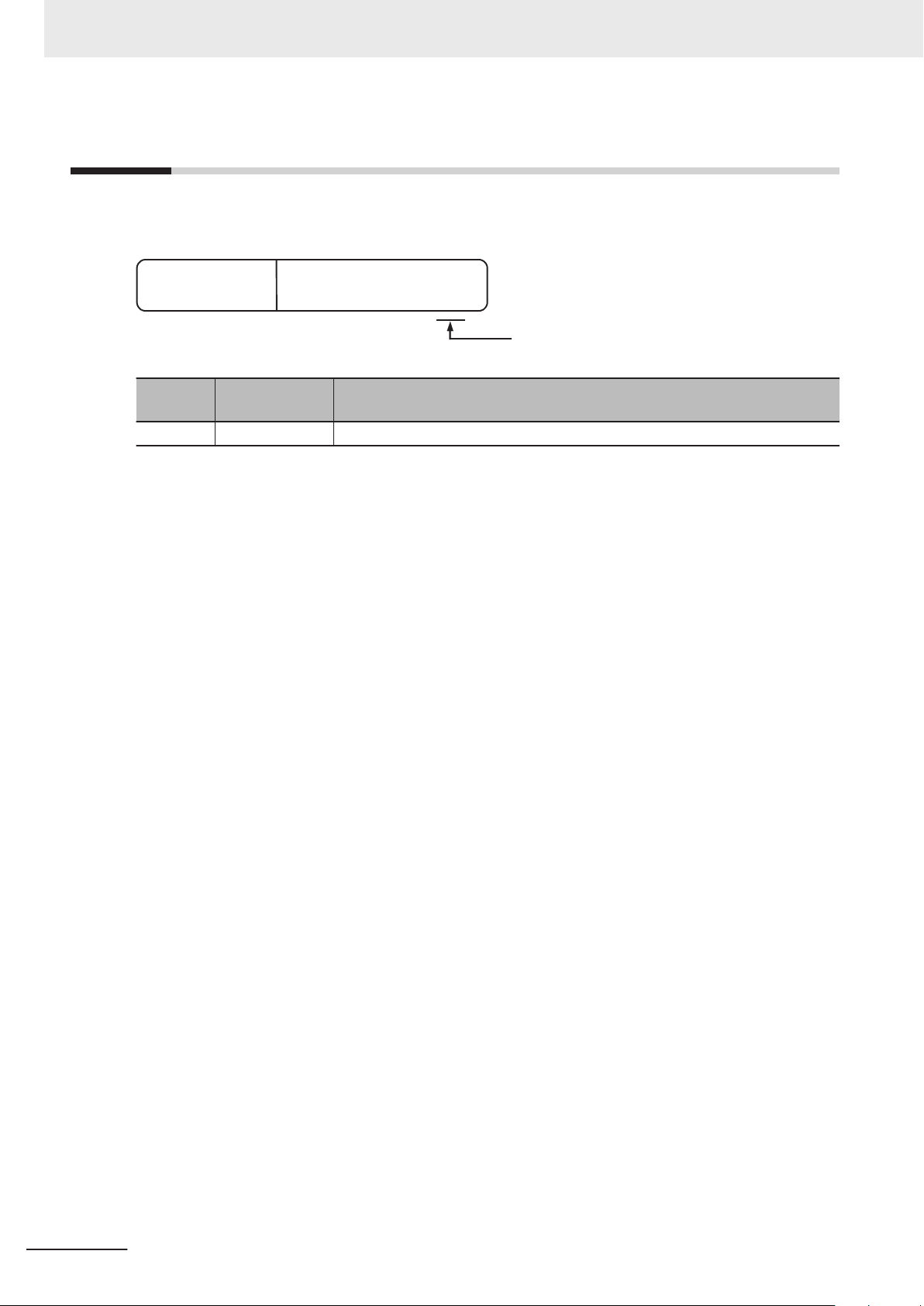
ID information indication
NJ501
- Ver.1.
££
PORT1 MAC ADDRESS:
££££££££££££
PORT2 MAC ADDRESS:
££££££££££££
Lot No. DDMYY
£
xxxx
Unit model
Lot number Serial number MAC address
Unit version
HW Rev.
£
RC Ver.1.
££
Hardware revision
R300
Robot Control Function
Module version
Versions
Versions
Hardware revisions and unit versions are used to manage the hardware and software in NJ-series
Units and EtherCAT slaves. The hardware revision or unit version is updated each time there is a
change in hardware or software specifications. Even when two Units or EtherCAT slaves have the
same model number, they will have functional or performance differences if they have different hard-
ware revisions or unit versions.
Checking Versions
You can check versions on the ID information indications or with the Sysmac Studio.
Checking Unit Versions on ID Information Indications
The unit version is given on the ID information indication on the side of the product.
NJ501-R£00
The ID information on the NJ-series NJ501-R300 CPU Unit is shown below.
Note
The hardware revision is not displayed for the Unit that the hardware revision is in blank.
22
NJ-series Robot Integrated CPU Unit User's Manual (O037)
Page 25
Versions
Checking Unit Versions with the Sysmac Studio
You can use the Sysmac Studio to check unit versions.
Checking the Unit Version of an NJ-series CPU Unit
You can use the Production Information while the Sysmac Studio is online to check the unit version
of a Unit. You can do this for the CPU Unit, CJ-series Special I/O Units, and CJ-series CPU Bus
Units. Y
ou cannot check the unit versions of CJ-series Basic I/O Units with the Sysmac Studio.
1 Double-click CPU Rack under Configurations and Setup - CPU/Expansion Racks
Multiview Explorer. Or, right-click CPU Rack under Configurations and Setup - CPU/
Expansion Racks in the Multiview Explorer and select Edit from the menu.
The Unit Editor is displayed.
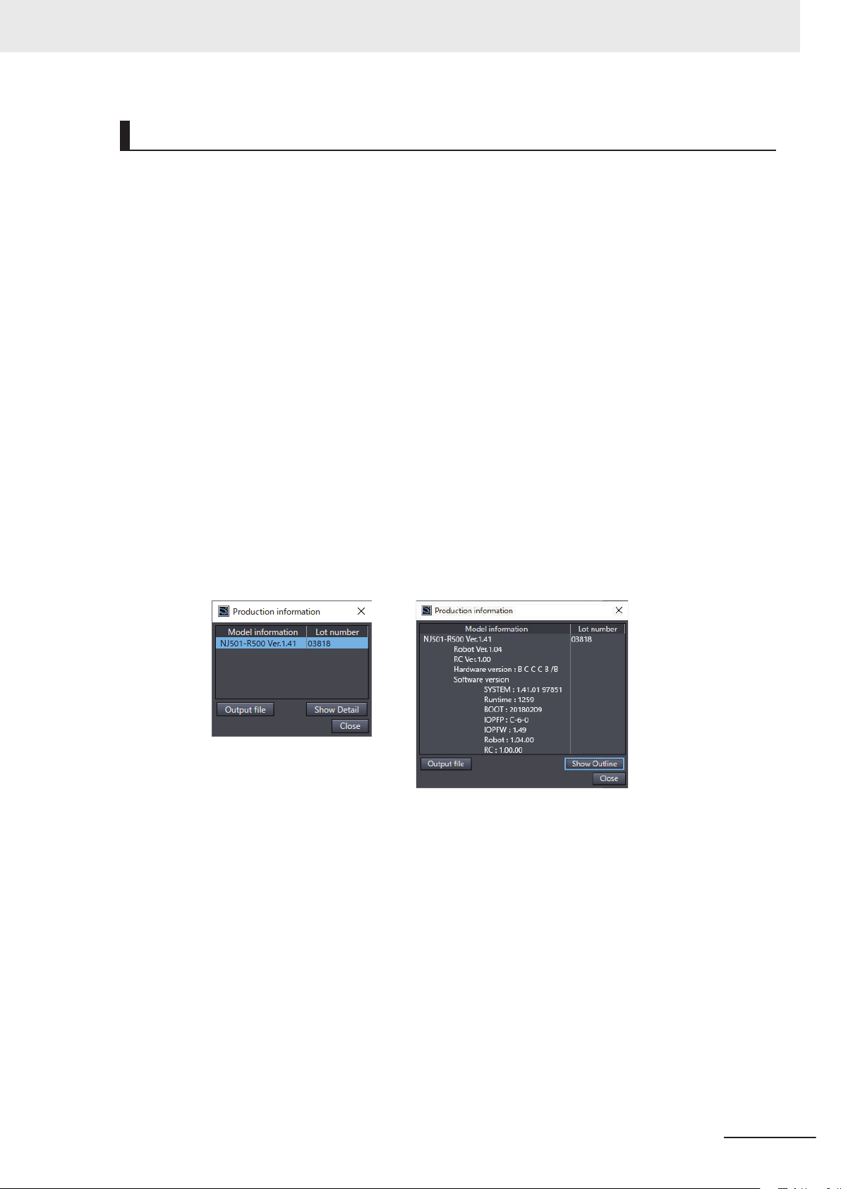
2 Right-click any open space in the Unit Editor and select Production Information.
The Production Information Dialog Box is displayed.
Changing Information Displayed in Production Information Dialog Box
1 Click the Show Detail or Show Outline Button at the lower right of the Production
Information Dialog Box.
The view will change between the production information details and outline.
in the
Outline View Detailed View
The information that is displayed is different for the Outline View and Detail View. The Detail
V
iew displays the unit version, hardware revision, and various versions. The Outline View dis-
plays only the unit version.
Note
The hardware revision is separated by “/” and displayed on the right of the hardware version. The
hardware revision is not displayed for the Unit that the hardware revision is in blank.
NJ-series Robot Integrated CPU Unit User's Manual (O037)
23
Page 26

Related Manuals
Related Manuals
The following are the manuals related to this manual. Use these manuals for reference.
Manual name Cat. No. Model numbers Application Description
NJ-series CPU Unit
Hardware User's Manual
NJ/NX-series CPU Unit
Software User’
NJ/NX-series Instructions
Reference Manual
NJ/NX-series CPU Unit
Motion Control User’
NJ/NX-series
Motion Control Instructions
Reference Manual
NJ/NX-series
CPU Unit
Built-in EtherCA
User
’s Manual
NJ/NX-series
CPU Unit
Built-in EtherNet/IP™ Port
s Manual
User’
NJ-series
Robot Integrated CPU Unit
s Manual
’
User
s Manual
s Manual
T® Port
W500
W501
W502
W507
W508
W505
W506
O037
NJ501-££££
NJ301-££££
NJ101-££££
NX701-££££
NX102-££££
NX1P2-££££
NJ501-££££
NJ301-££££
NJ101-££££
NX701-££££
NX102-££££
NX1P2-££££
NJ501-££££
NJ301-££££
NJ101-££££
NX701-££££
NX102-££££
NX1P2-££££
NJ501-££££
NJ301-££££
NJ101-££££
NX701-££££
NX102-££££
NX1P2-££££
NJ501-££££
NJ301-££££
NJ101-££££
NX701-££££
NX102-££££
NX1P2-££££
NJ501-££££
NJ301-££££
NJ101-££££
NX701-££££
NX102-££££
NX1P2-££££
NJ501-££££
NJ301-££££
NJ101-££££
NJ501-R£££
Learning the basic
specifications of the
NJ-series CPU Units,
including introductory
information, designing, installation, and
maintenance.
Mainly hardware information is provided.
Learning how to program and set up an
NJ/NX-series CPU
Unit.
Mainly software information is provided.
Learning detailed
specifications on the
basic instructions of
an NJ/NX-series
CPU Unit.
Learning about motion control settings
and programming
concepts.
Learning about the
specifications of the
motion control instructions.
Using the built-in
T port on an
EtherCA
NJ/NX-series CPU
Unit.
Using the built-in
EtherNet/IP port on
an NJ/NX-series
CPU Unit.
Using the NJ-series
Robot Integrated
CPU Unit.
An introduction to the entire NJ-series
system is provided along with the following information on the CPU Unit.
• Features and system configuration
• Introduction
• Part names and functions
• General specifications
• Installation and wiring
• Maintenance and inspection
The following information is provided on a
Controller built with an NJ/NX-series CPU
Unit.
• CPU Unit operation
• CPU Unit features
• Initial settings
• Programming based on IEC 61131-3
language specifications
The instructions in the instruction set (IEC
131-3 specifications) are described.
61
The settings and operation of the CPU
Unit and programming concepts for motion control are described.
The motion control instructions are described.
Information on the built-in EtherCAT port
is provided.
This manual provides an introduction and
provides information on the configuration,
features, and setup.
Information on the built-in EtherNet/IP port
is provided.
Information is provided on the basic setup,
tag data links, and other features.
Describes the settings and operation of
the CPU Unit and programming concepts
for OMRON robot control.
24
NJ-series Robot Integrated CPU Unit User's Manual (O037)
Page 27

Manual name Cat. No. Model numbers Application Description
Sysmac Studio
Robot Integrated System
Building Function with Robot
Integrated CPU Unit Operation Manual
Sysmac Studio
Robot Integrated System
Building Function with IPC
Application Controller Operation Manual
Sysmac Studio
3D Simulation Function Operation Manual
eV+3
s Manual
’
User
eV+3
Keyword Reference Manual
eCobra 600 and 800 Robot
with EtherCAT User
Viper 650 and 850 Robot with
EtherCAT User
Robot Safety Guide I590
eaching Pendant
T
T20
s Manual
User’
IPC Application Controller
s Manual
User’
NJ-series
NJ Robotics CPU Unit
s Manual
User’
NJ/NX-series
Troubleshooting Manual
Sysmac Studio Version 1
Operation Manual
NX-series
Position Interface Units
s Manual
User’
’s Guide
’s Guide
W595
W621
W618
I651
I652
I653
I654
I601 10046-010 Operating the OM-
I632 AC1-152000 Using the IPC Appli-
W539
W503
W504 SYSMAC
W524
SYSMAC-SE2£££
SYSMACSE200D-64
SYSMAC-SE2£££
SYSMACSE200D-64
SYSMAC-SE2
SYSMAC-SA4££
£-64
NJ501-R£££
NJ501-R£££
RL4-£££££££
RL6-£££££££
RL4-£££££££
RL6-£££££££
NJ501-4£££
NJ501-R£££
NX701-££££
NX102-££££
NX1P2NJ501-££££
NJ301-££££
NJ101-££££
-SE2£££
NX-EC0£££
NX-ECS£££
NX-PG0£££
£££
££££
Learning about the
operating procedures
and functions of the
Sysmac Studio to
configure Robot Integrated System using
Robot Integrated
CPU Unit.
Learning about the
operating procedures
and functions of the
Sysmac Studio to
configure Robot Integrated System using
IPC Application Con-
.
troller
Learning about an
outline of the 3D simulation function of the
Sysmac Studio and
how to use the function.
Operating the OMRON robot with the V
+ program.
Operating the OMRON robot with the V
+ program.
Using the eCobra. Describes the eCobra.
Using the Viper. Describes the Viper.
Learning how to use
the OMRON robot
safely.
RON robot with a
teaching pendant.
cation Controller.
Controlling robots
with NJ-series CPU
Units.
Learning about the
errors that may be
detected in an
NJ/NX-series Con-
.
troller
Learning about the
operating procedures
and functions of the
Sysmac Studio.
Learning how to use
NX-series Position
Interface Units.
Describes the operating procedures of the
Sysmac Studio for Robot Integrated CPU
Unit.
Describes the operating procedures of the
Sysmac Studio for IPC Application Controller.
Describes an outline, execution procedures, and operating procedures for the
3D simulation function of the Sysmac Studio.
Describes the V+ language to control the
OMRON robots.
Describes V+ keywords that are used in
the V+ language.
Describes how to use the OMRON robot
safely.
Describes the setup, operation, and user
maintenance for the Teaching Pendant
T20.
Describes the IPC Application Controller.
Describes the functionality to control robots.
Concepts on managing errors that may be
detected in an NJ/NX-series Controller
and information on individual errors are
described.
Describes the operating procedures of the
Sysmac Studio.
The hardware, setup, and functions for the
NX-series Incremental Encoder Input
Units, SSI Input Units, and Pulse Output
Unit are described.
Related Manuals
NJ-series Robot Integrated CPU Unit User's Manual (O037)
25
Page 28

Related Manuals
Manual name Cat. No. Model numbers Application Description
AC Servomotors/Servo Drives
1S-series with
Built-in EtherCA
cations User's Manual
AC Servomotors/Servo Drives
G5 Series with
Built-in EtherCAT® Communications User's Manual
T® Communi-
I586
I621
I576
I577
R88M-1£
R88D-1SN£
R88M-1AL£/ -1AM£
R88D-1SAN£-ECT
R88M-K
R88D-KN£-ECT
R88L-EC-£
R88D-KN£-ECT-L
-ECT
£
Learning how to use
the Servomotors/
Servo Drives with
built-in EtherCAT
Communications.
Learning how to use
the AC Servomotors/
Servo Drives with
built-in EtherCAT
Communications.
Describes the hardware, setup methods
and functions of the Servomotors/Servo
Drives with built-in EtherCAT Communications.
Describes the hardware, setup methods
and functions of the AC Servomotors/
Servo Drives with built-in EtherCAT Communications.
The Linear Motor Type models and dedicated models for position control are available in G5-series.
26
NJ-series Robot Integrated CPU Unit User's Manual (O037)
Page 29

Terminology
This section describes the terms that are used in this manual.
Term Description
continuous-path motion
IEC 61131-3 language
robots controllable
by NJ Robotics function
TCP A tip (Tool Center Point) defined in each OMRON robot.
V+ keyword A generic term for instructions that are used during a V+ program and monitoring com-
V+ language
V+ task A task that can execute a V+ program.
V+ program A control program written in the V+ language.
OMRON robot Specifies the OMRON robot controllable from the Robot Integrated CPU Unit.
shared variable
sequence control
program
hardware servo A servo system built into the robot amplifier.
user program A generic term for the collection of programs written in the ladder diagram, ST, and V+
recipe A set of product type data in the customer’s system.
recipe change Specifies that the product data and information (recipe) related to the production process
Robot Control Function Module
robot control instructions
Robot Integrated
CPU Unit
Terminology
A motion to move continuous operations smoothly without stopping motion of the OMRON robot.
A programming language to write a sequence control program.
Specify the controllable robots by the data processing for robot in the Motion Control
Function Module of the NJ-series CPU Unit.
The controllable robot consists of the 1S-series or G5-series Servomotor/Servo Drive
with built-in EtherCA
tomer.
The target position or path can be specified based on the TCP.
mand.
A programming language for OMRON robot control.
The robot consists of the robot amplifier and the robot arm connected to the robot ampli-
.
fier
A variable that can be shared between the sequence control program and V+ program.
A control program written in IEC 61131-3 language including the motion control.
languages.
are changed.
The target recipe for the Robot Integrated CPU Unit is a property from the present values of variables and a vision sensor
A software to perform robot control that is installed in the Robot Integrated CPU Unit.
FB instructions written in the sequence control program to control the OMRON robots.
They include an instruction to directly control the OMRON robots and an instruction to
execute or abort V+ programs assigned to the V+ tasks.
A CPU Unit that supports control function for the OMRON robot with the NJ-series CPU
Unit.
T communications and the robot arm that is prepared by the cus-
.
NJ-series Robot Integrated CPU Unit User's Manual (O037)
27
Page 30
O037-E1-01
R
evision code
Cat. No.
Revision History
Revision History
A manual revision code appears as a suffix to the catalog number on the front and back covers of the
manual.
Revision
code
01 August 2020 Original production
Date Revised content
28
NJ-series Robot Integrated CPU Unit User's Manual (O037)
Page 31

1
Introduction to Robot Integrated
CPU Unit
This section describes the features, basic system configuration, specifications, and
overall operating procedure of an NJ-series Robot Integrated CPU Unit
1-1 Features ..........................................................................................................1-2
1-2 System Configuration.................................................................................... 1-4
1-3 Specifications................................................................................................. 1-6
1-3-1 General Specifications .................................................................................... 1-6
1-3-2 Performance Specifications............................................................................. 1-6
1-3-3 Function Specifications ................................................................................... 1-6
1-3-4 V+ Program Specifications.............................................................................. 1-8
1-4 Basic Procedure of Operation ...................................................................... 1-9
.
1
NJ-series Robot Integrated CPU Unit User's Manual (O037)
1-1
Page 32
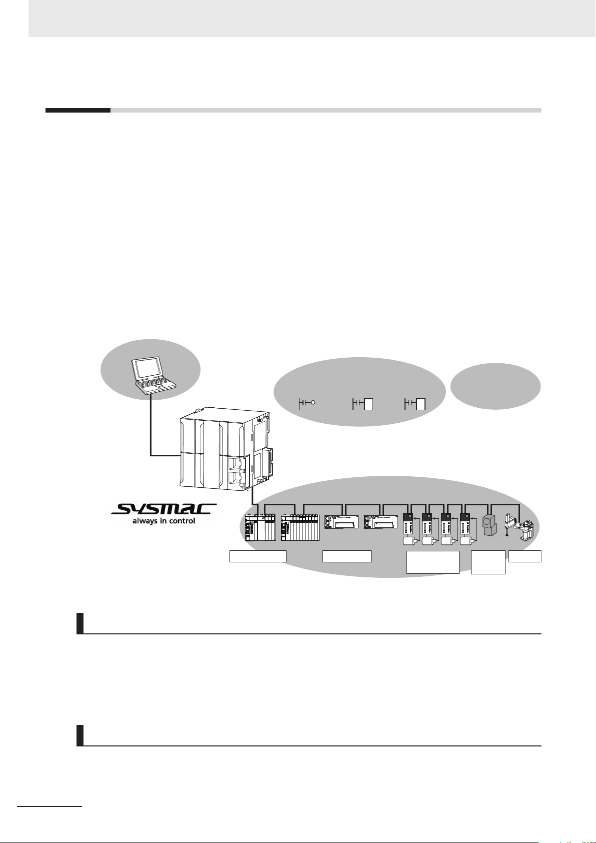
Motion controlSequence control
NJ-series
Robot Integrated
CPU Unit
IEC programming
Safety devices
Machine
vision
Servo Drives
and Inverters
I/O controls
EtherCAT control network
Sysmac Studio
Automation Software
Robots
V+ program
Robot control V+ language
1 Introduction to Robot Integrated CPU Unit
1-1
Features
The NJ-series Robot Integrated CPU Units are next-generation machine automation controllers that
provide the functionality and high-speed performance that are required for machine control. They pro-
vide the safety, reliability, and maintainability that are required of industrial controllers. The NJ-series
Controllers provide the functionality of previous OMRON PLCs, and they also provide the functionality
that is required for robot control. Synchronized control of I/O devices on high-speed EtherCAT can be
applied to robots, safety devices, vision systems, motion equipment, discrete I/O, and more.
OMRON offers the new Sysmac Series of control devices designed with unified communications spec-
ifications and user interface specifications.
The NJ-series Robot Integrated CPU Units are part of the Sysmac Series. You can use them together
with EtherCAT slaves, other Sysmac products, and the Sysmac Studio Automation Software to ach-
ieve optimum functionality and ease of operation. With a system that is created from Sysmac products,
you can connect components and commission the system through unified concepts and usability.
The Robot Control Function Module (sometimes abbreviated to “RC Function Module”) is a software
function module that is built into the Robot Integrated CPU Unit
The RC Function Module can perform robot control for up to 8 OMRON robots through the built-in
EtherCAT port on the Robot Integrated CPU Unit.
The OMRON robots are controlled with robot control instructions in the sequence control program.
1-2
Robot Control Function Module
Sequence Control Program
NJ-series Robot Integrated CPU Unit User's Manual (O037)
.
Page 33

1 Introduction to Robot Integrated CPU Unit
The sequence control program includes function blocks that are operated directly to the OMRON ro-
bots such as the robot joint interpolation, robot linear interpolation, stopping a robot, and other opera-
tions. The program also includes function blocks that controls V+ programs such as executing V+
tasks, aborting V+ tasks, and other operations.
V+ Program
The OMRON robots are controlled using V+ programs. The V+ programs are written in the V+ lan-
guage that is a special language for the robot control. You can easily realize various operation of the
OMRON robot using V+ programs.
In addition, the V+ program can use the interlock with a sequence control program (ladder diagram
and ST language) using shared variables.
Integrated Sequence Control and Motion Control
1-1 Features
1
A CPU Unit can perform both sequence control and motion control. You can simultaneously achieve
both sequence control and multi-axes synchronized control. Sequence control, motion control, and I/O
refreshing are all executed in the same control period.
The same control period is also used for the process data communications cycle for EtherCAT
enables precise sequence and motion control in a fixed period with very little deviation.
. This
Programming Languages Based on the IEC 61131-3 International
Standard
The Controllers support language specifications that are based on IEC 61131-3. To these, OMRON
has added our own improvements. Motion control instructions that are based on PLCopen® standards
and an instruction set (POUs) that follows IEC rules are provided.
Kinematics Function Supported
The kinematics function (NJ Robotics function) can perform data processing for robot in the Motion
Control Function Module (sometimes abbreviated to “MC Function Module”) to control robots that use
parallel link mechanism, Cartesian robots, and SCARA robots that are prepared by the customer.
Refer to the
matics function.
Note that the "kinematics function" is written as the "NJ Robotics function" in this manual.
NJ-series NJ Robotics CPU Unit User's Manual (Cat. No. W539) for details on the kine-
Data Transmission Using EtherCAT Communications
The OMRON robots are connected with EtherCAT communications to enable exchange of all control
information with high-speed data communications.
In addition, cyclic communications are performed with OMRON robots, Servo Drives and other devices
with EtherCAT communications, and the performance for the entire equipment is maximized
NJ-series Robot Integrated CPU Unit User's Manual (O037)
1-3
Page 34

Robots controllable by NJ Robotics function
FH-series Vision
Systems
Camera
Safety
devices
EtherNet/IP
EtherCAT
Sysmac Studio
NA-series
PT
T20 Pendant
(with built-in EtherCAT
communications)
Slave
Terminal
IPC Application
Controller
Vision sensor
OMRON
robot
Robot Integrated CPU Unit
NJ501-R£££
Encoder,
digital I/O
Front
panel
I/O control
external devices
1S-series Servo Drives
G5-series Servo Drives
USB
1 Introduction to Robot Integrated CPU Unit
1-2
System Configuration
This section describes the system configuration and components related to the Robot Integrated CPU
Unit.
1-4
The function of each component in the system is given below.
Component Function in the system
EtherCAT Controls for Servo Drives and OMRON robots through the EtherCAT master port that is
built into the Robot Integrated CPU Unit. It enables precise control in a fixed period with
very little deviation.
OMRON robot
T20 Pendant
Sysmac Studio An integrated development software for use with the Robot Integrated CPU Unit that al-
NA-series PT Displays various information and performs operation as required.
IPC Application
Controller
1S-series Servo
Drives
G5-series Servo
Drives
Robots controllable by NJ Robotics
function
Consists of the robot amplifier and the robot arm connected to the robot amplifier.
It connects with a Robot Integrated CPU Unit through EtherCA
It has digital I/O ports to enable control for the external devices.
*1
A teaching pendant for the OMRON robot. It connects to the OMRON robot and performs
a test run for the OMRON robot or teaching.
lows you to create programming and make device settings.
It is used when you instruct a recipe change to the
A Controller to manage a recipe and more than one OMRON robot controlled by the Robot
Integrated CPU Unit. It can perform image processing by connecting a vision sensor
Servo Drives with built-in EtherCAT communications.
Robots that can be controlled from the Robot Integrated CPU Unit that controls Servomotors/Servo Drives with built-in EtherCAT communications.
NJ-series Robot Integrated CPU Unit User's Manual (O037)
Robot Integrated CPU Unit
T communications.
.
.
Page 35

1 Introduction to Robot Integrated CPU Unit
Component Function in the system
Slave Terminal
FH-series Vision
Systems
Front panel Changes the operating mode of OMRON robot and executes a emergency stop.
I/O control external devices
Safety devices Safety devices such as a Safety Controller, safety sensor, and safety relay.
*1. Refer to the T20 Pendant User’
Precautions for Correct Use
• Always insert the included SD Memory Card when you use the robot control function with the
Robot Integrated CPU Unit.
Do not remove the SD Memory Card while power is supplied when you use the robot control
•
function with the Robot Integrated CPU Unit.
Doing so causes the robot control function to stop due to an error.
• The robot setting files and V+ program files in the SD Memory Card are required for the operation of the Robot Control Function Module.
Be careful not to overwrite or delete the robot setting files and V+ program files.
Consists of the NX-ECC20£ Communications Coupler Unit and NX Units that are connected to EtherCA
Unit through EtherCA
Various Units such as digital I/O, analog I/O are covered, therefore, you can use the NX
Units depending on the system demand.
Vision systems connected to the EtherCAT communications.
External devices to control from I/O ports of the NX Units or the robot.
They include a photoelectric sensor
T communications. It exchanges I/O data with a Robot Integrated CPU
T communications.
, an air cylinder
s Guide (Cat. No. I601) for details.
, a robot hand, and other devices.
1-2 System Configuration
1
NJ-series Robot Integrated CPU Unit User's Manual (O037)
1-5
Page 36

1 Introduction to Robot Integrated CPU Unit
1-3
1-3-1
1-3-2
Specifications
This section describes the general specifications, performance specifications, and function specifica-
tions for the Robot Integrated CPU Unit.
General Specifications
General specifications conform to the general specifications of the CPU Unit.
Refer to the NJ-series CPU Unit Hardware User’s Manual (Cat. No. W500) for details.
Performance Specifications
Performance specifications conform to the performance specifications of the NJ-series Controllers.
Refer to the NJ-series CPU Unit Hardware User’s Manual (Cat. No. W500) for details.
The performance specifications for the Robot Integrated CPU Unit are described below.
Item
Maximum number of controlled axes
Maximum number of controllable OMRON robots
Maximum number of robots controllable by NJ Robotics function
*1. This is the total for all axis types in Motion Control Function Module. Refer to the NJ/NX-series CPU Unit
Motion Control User’
This includes the number of axes used for the robots that are controlled with the NJ Robotics function.
*2. When the number of connected devices increases, the number of devices that can be connected to Ether-
CAT network is limited due to the restrictions for process data size of EtherCAT communications.
*3. The number of robots controllable by NJ Robotics function varies depending on the number of controlled
axes that you use. The number of controlled axes depends on the robot type. Refer to the NJ-series NJ
Robotics CPU Unit User's Manual (Cat. No. W539) for details.
s Manual (Cat. No. W507) for details on axis types.
*1
*2
R500 R400 R300
64 axes 32 axes 16 axes
*3
*2
NJ501-
8 max.
8 max.
1-3-3
Function Specifications
This section describes the functions that are specific to the NJ-series Robot Integrated CPU Units.
Basic Function
Category Function Specification Reference
Tasks Task management Adds V+ tasks along with the function supported by the NJ-series
CPU Units.
Programming
1-6
V+ program execution Executes the V+ program. page 1-8
Shared variables for sequence control program
and V+ program
V+ task control from sequence control program
Shares variables between the sequence control program and the V+
program.
Controls V+ tasks such as execution, end, and other operations
from the sequence control program.
NJ-series Robot Integrated CPU Unit User's Manual (O037)
page 2-12
page 4-7
page 4-6
Page 37

1 Introduction to Robot Integrated CPU Unit
Category Function Specification Reference
System-defined variables for robot control
I/O controls Read and write data for the digital I/O of the EtherCAT slave devices
Motion
control
Troubleshooting
Security Robot System Operation
SD Memory Card
Memory
management
Backup Backing up and restoring
Control with NJ Robotics
function
Event log Manages the event log for the OMRON robot along with the function
Error management Manages the OMRON robot errors along with the function supported
Error reset Clears the OMRON robot errors along with the function supported
Authority
CPU Unit write-protection
File explorer Uses the V+ File Browser in the Sysmac Studio to access V+ pro-
Clear All Memory Includes robot setting files and V+ programs along with the function
data for the Robot Integrated CPU Unit
Backing up and restoring
data for the OMRON robot
Can use the variables for monitoring the state of the RC Function
Module or each OMRON robot and variables for reading and writing
the built-in I/O in the each OMRON robot.
connected with EtherCA
CA
T Coupler Unit from the V+ program.
Controls Servomotors/Servo Drives connected with the EtherCAT
communications to control robots.
The function can realize the robot operation, single-axis operation,
and synchronized operation with the Motion Control Function Module.
supported by the NJ-series CPU Units.
by the NJ-series CPU Units.
by the NJ-series CPU Units.
Adds functions along with the function supported by the NJ-series
CPU Units.
grams and other data in the Robot Integrated CPU Unit.
supported by the NJ-series CPU Units.
Includes robot setting files and V+ programs along with the function
supported by the NJ-series CPU Units.
Backs up or restores data related to the OMRON robot. page 2-27
T communications or NX Units on the Ether-
page 2-8
page 3-4
page 2-4
page 11-1
page 2-29
page 2-29
page 2-17
page 2-22
page 2-24
1-3 Specifications
1
1-3-3 Function Specifications
Function for Robot Control Function Module
Catego-
ry
Robot
control
NJ-series Robot Integrated CPU Unit User's Manual (O037)
Control program for OMRON robot
Latching Robot position latch-
Function Specification Reference
Controls the OMRON robots with the sequence control program and V+ program.
Inputs an external trigger signal to the latch input of the OM-
ing
Robot built-in encoder latching
RON robot to output the current position.
Uses the latch function of the robot built-in encoder counter to
identify the encoder counter value at imaging by a vision sensor.
page 5-2
page 5-5
page 5-
6
1-7
Page 38

1 Introduction to Robot Integrated CPU Unit
Additional Information
Refer to the Sysmac Studio Robot Integrated System Building Function with Robot Integrated
CPU Unit Operation Manual (Cat. No. W595) for information on the debugging that is specific to
the Robot Control Function Module.
Refer to the Sysmac Studio Version 1 Operation Manual (Cat. No. W504) for information on the
debugging that is common to the NJ-series CPU Unit.
IPC Application Controller Cooperation Function
Function Specification Reference
Image processing with a vision sensor
Conveyor tracking Synchronizes the OMRON robot and the belt conveyor using the encoder
Recipe change from CPU
Unit
Detects and inspects a workpiece using a vision sensor. page 2-6
that is mounted to the belt conveyor
Requests a recipe change from the Robot Integrated CPU Unit to the IPC
Application Controller.
.
page 2-
page 2-
7
7
1-3-4
V+ Program Specifications
Refer to the eV+3 User's Manual (Cat. No. I651) and the eV+3 Keyword Reference Manual (Cat. No.
I652) for information on the V+ program specifications.
Precautions for Correct Use
The V+ keywords using for a hardware that does not support in the Robot Integrated CPU Unit,
such as DeviceNet, graphics, and IEEE1394, are not supported.
1-8
NJ-series Robot Integrated CPU Unit User's Manual (O037)
Page 39
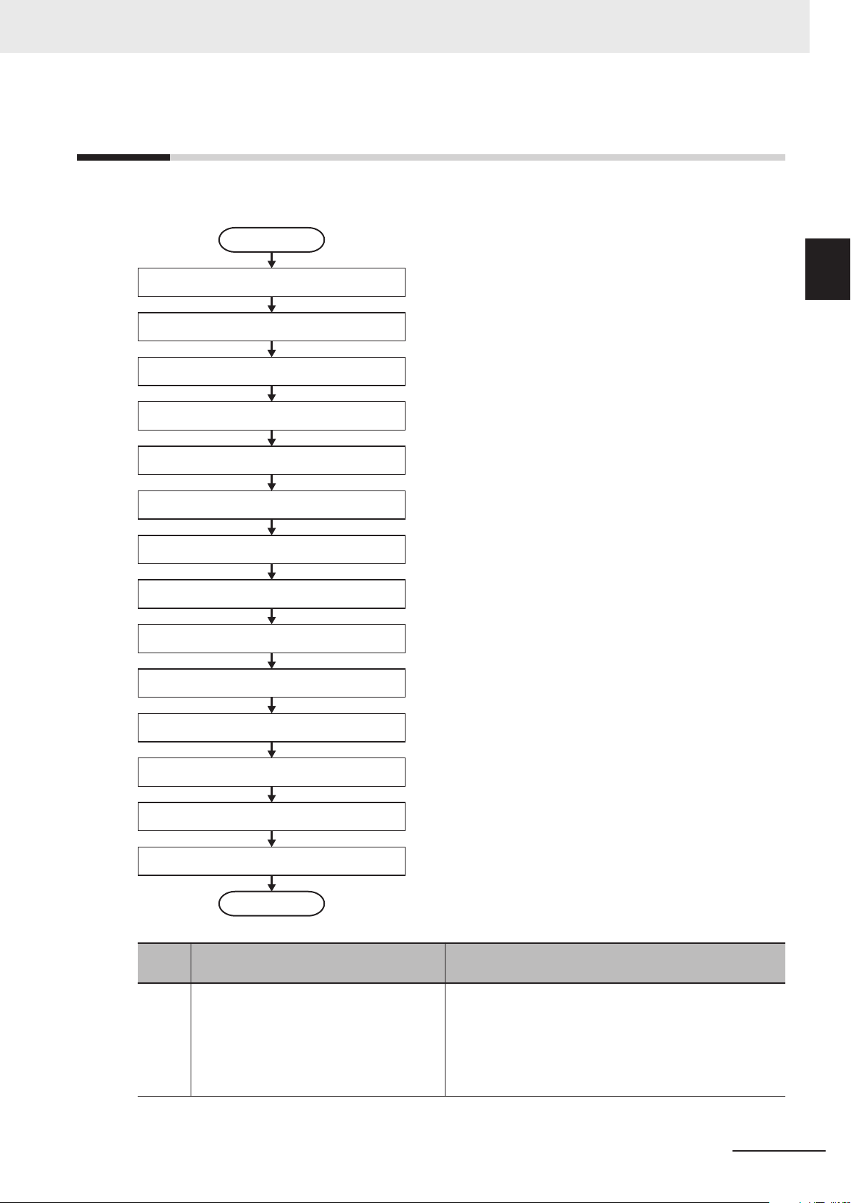
Create a project
*3
EtherCAT settings
*5
Transfer the settings and program
*11
Operation check on Controller
*12
Operation
*13
Maintenance and inspection
*14
Start
End
OMRON robot settings
*6
Hardware settings
*1
Installation and wiring
*2
Controller Setup
*4
I/O settings
*7
Programming
*8
Teaching in the simulation operation
*9
Offline debugging
*8
1 Introduction to Robot Integrated CPU Unit
1-4 Basic Procedure of Opera-
1-4
Basic Procedure of Operation
This section describes an example of the procedure to realize applications using the OMRON robots.
tion
1
Sym-
bol
*1 Make the settings for the hardware
switches on the devices and other settings.
If you operate a robot in the simulation operation, you can make the hardware settings later
Description Reference
Manuals for the OMRON robots that you use and the
EtherCAT slaves
.
NJ-series Robot Integrated CPU Unit User's Manual (O037)
1-9
Page 40

1 Introduction to Robot Integrated CPU Unit
Sym-
bol
*2 Install the devices. Wire the network and
the I/O.
If you operate a robot in the simulation operation, you can perform installation and
wiring later.
*3 Create a new project for the Robot Inte-
grated CPU Unit in the Sysmac Studio.
*4 Make the settings for the Robot Integrated
CPU Unit.
*5
*6 Make the robot control parameter settings. 3-3 Robot Setting Parameters on page
*7 Make the setting to control I/O from the
*8
Add the EtherCAT slaves including the
OMRON robots on the EtherCAT
make the settings.
user program.
Write the user program for OMRON robots
and peripheral devices with the sequence
control program and the V+ program.
Description Reference
• NJ-series CPU Unit Hardware User’
W500)
• Manuals for the OMRON robots that you use
Sysmac Studio Version 1 Operation Manual (Cat. No.
W504)
12
, and
2-5 Tasks on page 2-
2-6 EtherCAT Communications and Robot Control on
page 2-15
3-2 Robot Common Parameters on page 3-4
• Section 4 Program Design of Robot Control
4-1
• Section 5 Robot Control Function on page 5-1
• Section 6 Robot Control Instructions on page 6-1
• Section 7 Variables and Instructions on page 7-1
• Section 8 Common Command Instructions on page
8-1
• Section 9 Robot Command Instructions on page
9-1
• Section 10 System Control Instructions on page
10-1
*9 Perform teaching in the simulation opera-
tion.
• Sysmac Studio 3D Simulation Function Operation
Manual (Cat. No. W618)
• Sysmac Studio Robot Integrated System Build-
ing Function with Robot Integrated CPU Unit Operation
Manual (Cat. No. W595)
*10 Verify operation in the simulation opera-
tion. Make changes as required.
• 4-4-1 Offline Debugging on page
4-16
• Sysmac Studio 3D Simulation Function Operation
Manual (Cat. No. W618)
• Sysmac Studio Robot Integrated System Build-
ing Function with Robot Integrated CPU Unit Operation
Manual (Cat. No. W595)
*11 Transfer the settings and program from
the Sysmac Studio to the Robot Integrated CPU Unit and the EtherCAT slaves.
*12 Check the operations for the program and
the teaching position on the physical Controller. Make changes as required.
*13 Operate the Controller and the machine. ---
*14 Perform the troubleshooting for the error,
periodic inspections, and maintenance.
Sysmac Studio Robot Integrated System Building Function with Robot Integrated CPU Unit Operation Manual
(Cat. No. W595)
• 4-4-3 Online Debugging on page 4-17
• Sysmac Studio Robot Integrated System Build-
ing Function with Robot Integrated CPU Unit Operation
Manual (Cat. No. W595)
• T20 Pendant User’
• Section 11 Troubleshooting
s Guide (Cat. No. I601)
on page 11-1
• 2-9 Backup and Restore Operations on page 2-24
• NJ/NX-series Troubleshooting Manual (Cat. No. W503)
s Manual (Cat. No.
3-7
on page
1-10
NJ-series Robot Integrated CPU Unit User's Manual (O037)
Page 41

1 Introduction to Robot Integrated CPU Unit
Additional Information
Refer to the following manuals for information on the NJ-series common procedure and the procedure and connection with peripheral devices other than the OMRON robot.
• NJ-series CPU Unit Hardware User
• NJ/NX-series CPU Unit Software User’s Manual (Cat. No. W501)
• NJ/NX-series CPU Unit Motion Control User’s Manual (Cat. No. W507)
• NJ-series NJ Robotics CPU Unit User's Manual (Cat. No. W539)
’s Manual (Cat. No. W500)
1-4 Basic Procedure of Opera-
tion
1
NJ-series Robot Integrated CPU Unit User's Manual (O037)
1-11
Page 42

1 Introduction to Robot Integrated CPU Unit
1-12
NJ-series Robot Integrated CPU Unit User's Manual (O037)
Page 43

2
Robot Control System Configuration and Functions
This section outlines the internal structure of the Robot Integrated CPU Unit and describes the configuration and functions of the Robot Control Function Module.
2-1 Internal Configuration for the
2-2 Relationship between Robot Integrated CPU Unit and Robot ................... 2-3
2-3 Relationship between Robot Integrated CPU Unit and IPC Appli-
cation Controller.............................................................................................. 2-6
2-4 System-defined Variables for Robot Control............................................... 2-8
2-4-1 Overview of System-defined Variables for Robot Control ............................... 2-8
2-4-2 System of System-defined Variables for Robot Control .................................. 2-8
2-4-3 Attributes of System-defined Variables for Robot Control ..............................2-11
2-5 Tasks .............................................................................................................2-12
2-5-1 Tasks and Services for Robot Integrated CPU Unit ...................................... 2-12
2-5-2 Basic Operation of Tasks............................................................................... 2-12
2-5-3 Relationship between V+ Task and I/O Refreshing....................................... 2-14
2-6 EtherCAT Communications and Robot Control ........................................ 2-15
2-7 SD Memory Card Operations ......................................................................2-17
2-7-1 Included SD Memory Card Functions ........................................................... 2-18
2-7-2 Exclusive Control of File Access in the SD Memory Card............................. 2-20
2-8 Memory Management .................................................................................. 2-22
2-8-1 Data and File Locations................................................................................. 2-22
2-8-2 Clear All Memory........................................................................................... 2-22
2-9 Backup and Restore Operations ................................................................ 2-24
2-9-1 Backup and Restore Operations for Robot Integrated CPU Unit .................. 2-24
2-9-2 Backup and Restore Operations for OMRON Robot..................................... 2-27
2-10 Security .........................................................................................................2-29
2-10-1 Robot System Operation Authority................................................................ 2-29
2-10-2 CPU Unit Write Protection............................................................................. 2-29
Robot Integrated CPU Unit ......................... 2-2
2
NJ-series Robot Integrated CPU Unit User's Manual (O037)
2-1
Page 44

Robot Control
Function Module
PLC Function Module
O
S
Motion Control
Function Module
EtherCAT Master
Function Module
Other function
modules
*
1
2 Robot Control System Configuration and Functions
2-1
Internal Configuration for the Robot Integrated CPU Unit
This section provides information about the internal mechanisms of the NJ-series Robot Integrated
CPU Unit.
The Robot Integrated CPU Unit has the following software configuration.
The Robot Control Function Module is a software module that performs robot control for the OMRON
robots.
*1. Refer to the NJ/NX-series CPU Unit Software User’s Manual (Cat. No. W501) for information on other function
modules.
The PLC Function Module resides on the OS, and each function module is executed. A description of
each function module is given in the following table.
Function module
PLC Function
Module
Robot Control
Function Mod-
*1
ule
Motion Control
Function Module
*2
EtherCA
Function Module
*1. The Robot Control Function Module is sometimes abbreviated to "RC Function Module".
*2. The Motion Control Function Module is sometimes abbreviated to "MC Function Module".
T Master
Abbreviation
PLC This module manages overall scheduling, executes the user program, sends
commands to the Robot Control Function Module, and provides interfaces to
USB and the SD Memory Card.
RC This module performs robot control for the OMRON robot according to the com-
mands from robot control instructions that are executed in the user program and
the commands from V+ programs. It sends data to the EtherCA
tion Module.
MC
ECAT This module communicates with the EtherCAT slaves as the EtherCAT master.
This module performs motion control according to the commands from motion
control instructions that are executed in the user program. It sends data to the
EtherCAT Master Function Module.
It is used for the robot control with the NJ Robotics function and the motion control for a transfer equipment and a press machine.
Description
T Master Func-
2-2
NJ-series Robot Integrated CPU Unit User's Manual (O037)
Page 45

EtherCAT Master
Function Module
Robot Integrated CPU Unit
EtherCAT
communications
EtherCAT
communications
M
E
Motion control
instruction
Servo Drive
Command
interpretation
Data
processing
Data
processing
for robot
Communications
processing
Communications
processing
Command
interpretation
Status
Control
Position
control
Velocity
control
Toque
control
Configure a feedback system.
Not configure a feedback system.
Actual value
OMRON robot
Sequence
control program
RC Function
Module
Robot control
instruction
V+ program
*1
Command
interpretation
MC Function
Module
command
value
Robot amplifier
Communications
processing
Path calculation
Servo control
Status
monitoring
Robot arm
2 Robot Control System Configuration and Functions
2-2 Relationship between Robot Integrated
2-2
Relationship between Robot Integrated CPU Unit and Robot
The Robot Integrated CPU Unit supports the RC Function Module and the MC Function Module.
• The RC Function Module can control the OMRON robot through the built-in EtherCAT port from the
robot control instructions and V+ programs.
• The MC Function Module can perform motion control through the built-in EtherCAT port on the CPU
Unit. Cyclic communications are performed with Servo Drives and other devices that are connected
to the EtherCAT port to enable high-speed and high-precision machine control.
In addition, the NJ Robotics function can perform data processing for robot in the MC Function Mod-
ule to control robots that use parallel link mechanism, Cartesian robots, and SCARA robots that are
prepared by the customer.
A Robot Integrated CPU Unit can control the OMRON robot and the robots that are prepared by the
customer.
(¡: Controllable, Ï: Not controllable)
Robot to control
OMRON robot
Robots controlled by NJ Robotics func-
*2
tion
*1. Refer to Controllable OMRON Robots on page 2-4 for information on the OMRON robot.
*2. Refer to Robot Types Controllable by NJ Robotics Function on page 2-5 for information on the robot con-
trollable by the NJ-Robotics function.
*1
Robot control in-
struction
¡ ¡ Ï
Ï Ï ¡
V+ program
Motion control in-
struction
CPU Unit and Robot
2
*1. The V+ program using the RC Function Module and robot setting files are saved in an SD Memory Card.
NJ-series Robot Integrated CPU Unit User's Manual (O037)
2-3
Page 46

2 Robot Control System Configuration and Functions
Refer to 2-7-1 Included SD Memory Card Functions on page 2-
18 for details.
Robot Control Function Module
A program that controls the OMRON robot is written with robot control instructions and V+ programs.
• The sequence control program can control OMRON robots with robot control instructions only. The
program can also control the OMRON robot by starting and stopping the V+ tasks with the robot
control instructions.
Y
ou can use robot variables if the current position and status of the OMRON robot are monitored in
the sequence control program.
In the same way, the robot built-in I/O of OMRON robots perform the control with robot I/O variables
in the sequence control program.
• In the V+ program, the RC Function Module analyzes the V+ program line by line and sends instruc-
tions (V+ keywords) and command values to the OMRON robot connected to the EtherCAT.
After receipt of an instruction (V+ keyword) or a command value, the OMRON robot performs path
calculation and controls the robot arm.
The present value and status of the OMRON robot are sent through the EtherCAT to the RC Func-
tion Module.
Controllable OMRON Robots
The following OMRON robots that support EtherCAT communications can be controlled.
*1
OMRON robot
SCARA robot
Articulated robot
*1. Refer to the OMRON robot manuals for information on the specifications of the OMRON robot.
*2. Only the models that support EtherCAT communications are available.
Product name Model
eCobra
*2
Viper
*2
RL4-£££££££
RL6-£££££££
Motion Control Function Module
The MC Function Module interprets commands, performs data processing based on the commands
from the sequence control program in the CPU Unit, and performs Servo Drive control.
The NJ Robotics function performs data processing for robot in the MC Function Module and controls
Servomotors/Servo Drives with built-in EtherCAT communications to perform robot control.
• When motion control instructions are executed in the sequence control program, the MC Function
Module interprets the resulting commands.
• The MC Function Module then performs motion control processing at a fixed period based on the
results of the command interpretation. It generates command values to send to the Servo Drive. The
following command values are generated: target position, target velocity, and target torque.
• The command values are sent by using PDO communications during each process data communi-
cations cycle of EtherCAT communications.
• The Servo Drive performs position loop control, velocity loop control, and torque loop control based
on the command values received during each process data communications cycle of EtherCAT
communications.
• The encoder's current value and the Servo Drive status are sent to the CPU Unit during each proc-
ess data communications cycle of EtherCAT communications.
2-4
NJ-series Robot Integrated CPU Unit User's Manual (O037)
Page 47

2 Robot Control System Configuration and Functions
Additional Information
• Motion control processing and process data communications in EtherCAT communications
are performed during the same time period.
• The MC Function Module controls the Servo Drive, which contains the position control loop,
velocity control loop, and torque control loop.
•
Refer to the NX-series Position Interface Units User’s Manual (Cat. No. W524) for information
on the configuration to use the NX-series Position Interface Units.
Robot Types Controllable by NJ Robotics Function
The robot types that can be controlled by NJ Robotics function are as follows: Delta3, Delta3R,
Delta2, Cartesian 3D, Cartesian 3D Gantry, Cartesian 2D, Cartesian 2D Gantry
pansion1, SCARA RRP, SCARA RRP+R, SCARA PRR, and SCARA PRR+R
Refer to the NJ-series NJ Robotics CPU Unit User's Manual (Cat. No. W539) for details on robot
types.
Motion Control Instructions for NJ Robotics Function
In addition to the motion control instructions that you can use with an NJ501-1£££ Unit, you can
use the following motion control instructions with the NJ Robotics function.
The motion control instructions for the NJ Robotics function are classified as the instructions for ax-
es group commands.
, H-Bot, T-Bot, Ex-
2-2 Relationship between Robot Integrated
CPU Unit and Robot
2
Classification
Instructions for axes group commands
Instruction Name
MC_SetKinTransform Set Kinematics Transformation
MC_DefineCoordSystem Define Coordinate
MC_DefineToolTransform Define Tool Coordinate
MC_GroupMon Group Monitor
MC_MoveTimeAbsolute Time-specified Absolute Positioning
MC_SyncLinearConveyor Start Conveyor Synchronization
MC_SyncOut End Synchronization
MC_InverseKin Inverse Kinematics
MC_RobotJog Axes Group Jog
MC_MoveDirectAbsolute Joint Interpolated Point-to Point Movement
Motion control instruction
Refer to the NJ-series NJ Robotics CPU Unit User's Manual (Cat. No. W539) for information on the
motion control instructions for NJ Robotics functions.
Refer to the NJ/NX-series Motion Control Instructions Reference Manual (Cat. No. W508) for infor-
mation on the motion control instructions that can be used for the NJ501-1£££.
NJ-series Robot Integrated CPU Unit User's Manual (O037)
2-5
Page 48

EtherCAT Master
Function Module
Robot Integrated CPU Unit
EtherCAT
communications
Communications
processing
Actual value
OMRON robot
Sequence
control program
RC Function
Module
Robot control
instruction
V+ program
Command
interpretation
command
value
Robot amplifier
Communications
processing
Path calculation
Servo control
Status
monitoring
Robot arm
IPC Application Controller
Ethernet
communications
User Application Application Manager
Robot
Vision
Manager
Process
Manager
Recipe
Manager
2 Robot Control System Configuration and Functions
2-3
Relationship between Robot Integrated CPU Unit and IPC Application Controller
This section describes the cooperation of the Robot Integrated CPU Unit and a software that is instal-
led in the IPC Application Controller.
Refer to the Sysmac Studio Robot Integrated System Building Function with IPC Application Controller
Operation Manual (Cat. No. W621) for information on the software that is installed in the IPC Applica-
tion Controller.
Image Processing with Vision Sensor
You can detect and inspect a workpiece with the vision sensor connected to the IPC Application Con-
troller.
The image processing uses the Robot V
2-6
Refer to the Sysmac Studio Robot Integrated System Building Function with IPC Application Controller
Operation Manual (Cat. No. W621) for details.
ision Manager function in the IPC Application Controller.
NJ-series Robot Integrated CPU Unit User's Manual (O037)
Page 49

Vision data
IPC Application Controller
EtherCAT
Ethernet
Robot Integrated CPU Unit
NJ501-R£££
Belt position
Belt conveyor
*1
*2
*3
*4
*5
2 Robot Control System Configuration and Functions
Conveyor Tracking
You can make the operation of OMRON robot follow the operation of belt conveyor using the encoder
that is mounted to the belt conveyor to configure applications for conveyor tracking.
2-3 Relationship between Robot Integrated
CPU Unit and IPC Application Controller
2
*1. Robot path (conveyor tracking)
*2. Workpiece position detected by the image processing
*3. Input a shutter signal as a latch signal
*4. Pulse of encoder mounted to the belt conveyor
*5. Latched belt position
The conveyor tracking uses the Pack Manager function and Process Manager function in the IPC Ap-
plication Controller.
Refer to the
Sysmac Studio Robot Integrated System Building Function with IPC Application Controller
Operation Manual (Cat. No. W621) for details.
Request for Recipe Change
You can request a recipe change from the Robot Integrated CPU Unit to the IPC Application Control-
ler
.
The recipe change uses the Recipe Manager function and Robot V
Application Controller.
Refer to 5-4 Changing Recipe on page 5-10 for information on how to create the user program to
request a recipe change.
ision Manager function in the IPC
NJ-series Robot Integrated CPU Unit User's Manual (O037)
2-7
Page 50

2 Robot Control System Configuration and Functions
2-4
2-4-1
System-defined Variables for Robot Control
This section describes the system-defined variables for robot control that belong to the RC Function
Module.
In a Robot Integrated CPU Unit, in the same way for an NJ-series CPU Unit, you use variables in the
sequence control program to access I/O and memory in the CPU Unit.
You also use the "system-defined variables for robot control" to access the state of OMRON robot and
Robot built-in I/O.
Overview of System-defined Variables for Robot Control
System-defined variables are provided in advance in an NJ-series Controller. The variables and all at-
tributes are defined by the system. They have specific functions. You cannot change the variable
names or any other attributes.
Of these, system-defined variables that belong to the RC Function Module are called "system-defined
variables for robot control".
Of these, system-defined variables that belong to current errors (events) in the RC Function Module
are called "error status variables".
Refer to 7-1 System-defined variables for Robot Control on page 7-2 for details on the list of sys-
tem-defined variables for robot control.
Refer to Error Status Variables on page 11-7 for information on the error status variables.
Level 1 Level 2 Level 3 Description
System-defined
variables
Refer to the NJ/NX-series CPU Unit Software User’
tem-defined variables for an NJ-series Controller.
System-defined variables for robot control
Error status variables Robot Control Error
Robot control common variable
Robot variables Monitor the status of each OMRON robot.
Robot I/O variables Read and write the robot built-in I/O of
Status
Robot Control Common Error Status
Robot Error Status Gives the collective error status of all error
s Manual (Cat. No. W501) for details on the sys-
Monitor the common status of the RC
Function Module.
each OMRON robot.
Gives the collective error status of all error
status for the RC Function Module.
Gives the collective error status of all errors that occur for common processing in
the RC Function Module.
status for each OMRON robot.
2-4-2
2-8
System of System-defined Variables for Robot Control
System-defined variables for robot control consist of information representing the status of the RC
Function Module, control command to the OMRON robots connected to EtherCAT communications,
status information, and the portion of the robot control parameter settings used to perform robot con-
trol.
NJ-series Robot Integrated CPU Unit User's Manual (O037)
Page 51

ID211
0
1
3
2
4
5
7
6
8
9
11
10
12
13
14
15
D
C24V
7mA
C
OM
MACH
No
.
AD042
RUN
ERC
ERH
B1 A1
x10
1
x1
0
0
0
9
8
7
6
5
4
3
2
1
0
9
8
7
6
5
4
3
2
1
0 1 2 3 4 5 6 7
8
9
10 11 12 13 14 15
CPU Unit
Main memory
Sequence
control program
System-defined
variable for
robot control
OMRON
robot
Status
Robot built-in
I/O
Read
Robot variables
RC Function
Module
Robot control
common variable
Robot I/O
variables
Sysmac Studio
EtherCA
T
communi
cations
Write
2 Robot Control System Configuration and Functions
You can access system-defined variables for robot control from the sequence control program, and
read and write them from the Sysmac Studio.
Among the values of system-defined variables for robot control, the TCPActPos
TCP for OMRON Robot) and JointActPos (Actual Position of Each Joint of OMRON Robot) robot vari-
ables retain the previous values even if EtherCAT communications have been disconnected or not es-
tablished.
(Actual Position of
2-4 System-defined Variables for Robot Con-
Precautions for Correct Use
Access the _EC_PDSlavTbl (Process Data Communicating Slave Table) system-defined variable and check that the process data of the slave is enabled (operational) before the robot variables that are not
TCPActPos (Actual Position of TCP for OMRON Robot) and JointActPos (Actual Position of Each Joint of OMRON Robot) and robot I/ I/O variables are used.
Refer to the NJ/NX-series CPU Unit Built-in EtherCAT Port User’s Manual (Cat. No. W505) for
information on the _EC_PDSlavTbl (Process Data Communicating Slave Table) system-defined
variable.
trol
2
2-4-2 System of System-defined Variables for Robot Control
The system-defined variables for robot control are updated every primary period.
Information from the OMRON robots, which is obtained via EtherCAT communications, is reflected in
the system-defined variables for robot control within the control period and can be accessed when the
user program is executed.
Robot Control Common Variable
The robot control common variable can monitor the common status of the RC Function Module.
The robot control common variable is a system-defined variable. The variable name _RC_COM is
used for the robot control common variable. The data type is _sRC_COMMON_REF, which is a struc-
ture.
Refer to 7-1-1 Robot Control Common Variable on page 7-2 for details on the robot control common
variable.
Robot Variables
The robot variables can monitor the current position and state of the OMRON robot.
NJ-series Robot Integrated CPU Unit User's Manual (O037)
2-9
Page 52

2 Robot Control System Configuration and Functions
The robot variable is a system-defined variable. The variable names _RC_RBT[0..7] are used for the
robot variables. The data type is _sRC_RBT_REF, which is a structure.
Y
ou can use robot variables to access status and position of OMRON robots from the sequence con-
trol program.
Each robot variable has two variable names: One is the system-defined variable name and the other is
the variable name that is assigned when you add an OMRON robot on the Sysmac Studio.
You can change the variable names that you created on the Sysmac Studio to any variable names for
each OMRON robot.
• The system-defined variables have the following variable names.
_RC_RBT[0] to _RC_RBT[7]
• The default variable names that are assigned when you add an OMRON robot on the Sysmac Stu-
dio are shown below.
You can change these variable names to any variable names for each OMRON robot from the Sys-
mac Studio.
RC_Robot001 to RC_Robot008 (default)
You can use either the system-defined variable names or the variable names of the OMRON robots
that you added on the Sysmac Studio in the user program.
The relationship between system-defined variable names and robot numbers is shown below.
Robot variable name in the system-defined
variables
(AT specification in global variable table)
_RC_RBT[0] RC_Robot001 1
_RC_RBT[1] RC_Robot002 2
: : :
_RC_RBT[7] RC_Robot008 8
*1. Refer to 3-3-2 Robot Basic Settings on page 3-7 for information on the robot number
Robot variable name when the robot is
added on the Sysmac Studio
(Default)
.
Robot number
*1
Refer to Operation States of the OMRON Robots on page 4-22 for information on the definition of
each robot status that is stored in robot variables.
Refer to
7-1-2 Robot Variables on page 7-3 for details on robot variables.
Robot I/O Variables
The robot I/O variables are system-defined variables for handling the robot built-in I/O. The variable
names _RC_RBT_IO[0..7] are used for the robot I/O variables. The data type is _sRC_RBT_IO_REF,
which is a structure.
Y
ou can use robot I/O variables to access the robot built-in I/O of OMRON robots from the sequence
control program.
2-10
Each robot I/O variable has two variable names: One is the system-defined variable name and the
other is the variable name that is assigned when you add a robot on the Sysmac Studio.
• The system-defined variables have the following variable names.
_RC_RBT_IO[0] to _RC_RBT_IO[7]
• The variable names that are created on the Sysmac Studio are as follows.
You can change these variable names to any variable names for each OMRON robot from the Sys-
mac Studio.
RC_Robot001_IO to RC_Robot008_IO (default)
NJ-series Robot Integrated CPU Unit User's Manual (O037)
Page 53
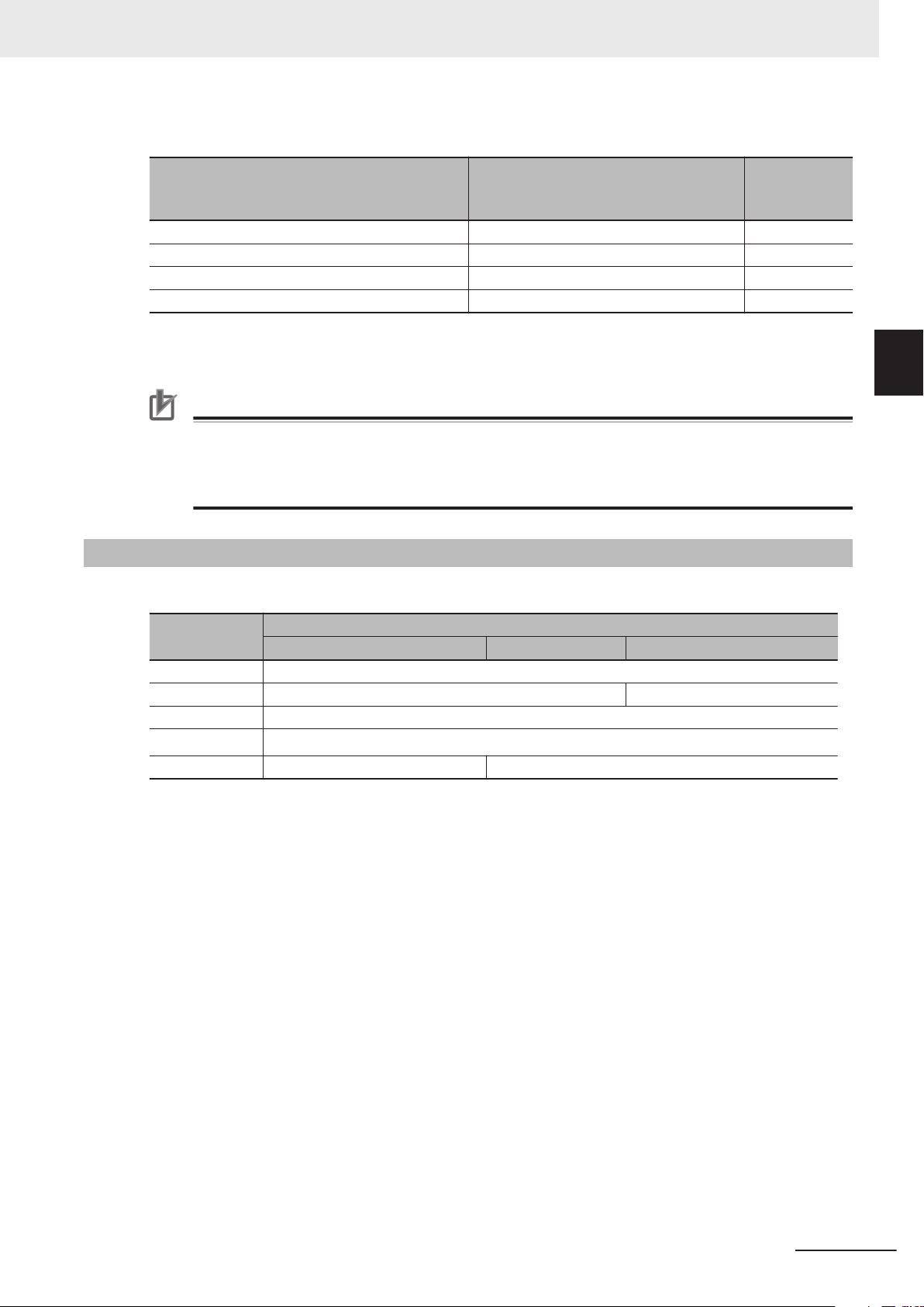
2 Robot Control System Configuration and Functions
The relationship between system-defined variable names and robot numbers is shown below.
2-4 System-defined Variables for Robot Con-
2-4-3
Robot I/O variable name in the system-de-
fined variables
(AT specification in global variable table)
_RC_RBT_IO[0] RC_Robot001_IO 1
_RC_RBT_IO[1] RC_Robot002_IO 2
: : :
_RC_RBT_IO[7] RC_Robot008_IO 8
*1. Refer to 3-3-2 Robot Basic Settings on page 3-7 for information on the robot number
Robot I/O variable name when the ro-
bot I/O is added on Sysmac Studio
(Default)
.
Refer to 7-1-3 Robot I/O Variables on page 7-7 for details on robot I/O variables.
Precautions for Correct Use
The robot built-in I/O of OMRON robots can be read and written to the same robot built-in I/O
device from both the sequence control program and V+ program.
However, write from only one of the programs to the output device of the same robot built-in I/O
because exclusive processing is complicated.
Attributes of System-defined Variables for Robot Control
The attributes of system-defined variables for robot control are summarized as follows.
Robot num-
*1
ber
trol
2
2-4-3 Attributes of System-defined Variables for Robot Control
Attribute
Global/local Global variables
R/W access Read only Read and write are possible.
Retain Not retained.
Network Publish
Name Fixed. Different names can be created on the Sysmac Studio.
*1. Variables are published on the network with the variable names of the system-defined variables. Different
variable names that you created on the Sysmac Studio are not published on the network.
Robot control common variable Robot variables Robot I/O variables
Published.
*1
System-defined variables for robot control
NJ-series Robot Integrated CPU Unit User's Manual (O037)
2-11
Page 54

2 Robot Control System Configuration and Functions
2-5
2-5-1
Tasks
This section provides information on tasks for the Robot Integrated CPU Unit and task operation.
Refer to the NJ/NX-series CPU Unit Software User’s Manual (Cat. No. W501) for details on the tasks.
Tasks and Services for Robot Integrated CPU Unit
Tasks are used to specify an execution condition and execution order to a series of processes, such
as I/O refreshing and user program execution.
The NJ-series Robot Integrated CPU Unit support the following tasks.
Type of task Task name
Tasks that execute programs at a fixed period Primary periodic task
Priority-16, 17, or 18 periodic task
Tasks that execute programs only once when the execution conditions for
the tasks are met
Tasks that execute V+ programs operated on the system services V+ task
The V+ task can set a maximum of 64 tasks (0 to 63).
Refer to the eV+3 User's Manual (Cat. No. I651) for details on the V+ tasks.
Refer to the NJ/NX-series CPU Unit Software User’
tasks that are not V+ tasks.
s Manual (Cat. No. W501) for information on the
Priority-8 or 48 event task
Precautions for Correct Use
The robot control instructions can be used only for the primary periodic task.
If robot control instructions are used in any other tasks, an error will occur when the user program is built on the Sysmac Studio.
Refer to 6-1 Overview of Robot Control Instructions on page 6-2 for information on the robot
control instructions.
Task Period of Primary Periodic Task
The task period of primary periodic task for the Robot Integrated CPU Unit is given below.
Item Specification Initial value
Task period of primary periodic task 1 ms, 2 ms, or 4 ms 2 ms
Precautions for Correct Use
If the OMRON robot is connected, set the EtherCAT communications cycle that is supported by
the OMRON robot to the task period of the Robot Integrated CPU Unit.
Refer to the OMRON robot manuals for information on EtherCA
tions of the OMRON robot.
T communications specifica-
2-5-2
2-12
Basic Operation of Tasks
The Robot Integrated CPU Unit cannot execute more than one periodic task and event task at the
same time.
NJ-series Robot Integrated CPU Unit User's Manual (O037)
Page 55

SS
UPG
MC RC
I/O
High
Low
Execution
priority
Primary period Primary period
Primary
periodic task
SS
UPG
MC RC
I/O
Primary
periodic task
2 Robot Control System Configuration and Functions
The order in which tasks are executed depends on the execution priority that is set for each task.
However, the V+ tasks are operated on the system services and up to 64 tasks are executed in se-
quence with time slicing according to the priority of the V+ tasks.
T
o operate a robot with V+ tasks as designed in advance, you must obtain the the system service exe-
cution time to design tasks.
Refer to A-2 Guideline for System Service Execution Time Ratio on page A-3 for information on the
guideline for the system service execution time.
This section explains the relationship between the primary periodic task for the Robot Integrated CPU
Unit and the V+ task.
Refer to the NJ/NX-series CPU Unit Software User’s Manual (Cat. No. W501) and the eV+3 User's
Manual (Cat. No. I651) for information on the task operation other than above, task execution priority
and system services.
Precautions for Correct Use
If sufficient system service times for execution of V+ tasks cannot be allocated due to the processing time of the user program or the system services other than V+ tasks, the V+ tasks may
be executed during more than one period.
Always confirm the operation of V+ tasks in the actual operating conditions.
If the intended operations are not performed, make unused time by extending the primary task
period or reviewing the processing.
2-5 Tasks
2
2-5-2 Basic Operation of Tasks
Operation of Primary Periodic Task
The primary periodic task includes operations such as system common processing, motion control,
and robot control in addition to I/O refreshing and user program execution.
After the execution of the primary periodic task, the robot control instruction written in the sequence
control program executes in the robot control processing of the next primary periodic task.
The V+ task is executed on the system services.
The operation for the NJ501-R£££ is given below
The V+ task and other services are executed on the system services.
Abbreviation Description
I/O I/O refreshing
UPG User program execution
MC Motion control
RC Robot control
.
NJ-series Robot Integrated CPU Unit User's Manual (O037)
2-13
Page 56

Primary periodic
task
System services
O
UI M R
V
Primary period Primary period Primary period Primary period Primary period
O UI M R
V
O UI M R
V
O UI M R
V
O UI M R
V
Write to output variables
Read input variables
2 Robot Control System Configuration and Functions
Abbreviation Description
SS System service execution including V+ task
2-5-3
Relationship between V+ Task and I/O Refreshing
The digital I/O of the EtherCAT slave devices connected to the Robot Integrated CPU Unit or the NX
Units on the EtherCAT Coupler Unit can be read and written from the V+ program assigned to the V+
task.
However
the NX Units on the EtherCAT Coupler Unit cannot be read and written directly from the V+ program,
so they are read and written through the RC Function Module.
The V+ program and the timing of I/O refreshing are shown in the following figure.
When output variables are written in the V+ program, data is output at the timing of solid line in the
following figure.
When input variables are read in the V+ program, the value input at the timing of dotted line in the
following figure is read.
, the digital I/O of the EtherCAT slave devices connected to the Robot Integrated CPU Unit or
Abbreviation Description
O Output refreshing
I Input refreshing
U User program execution
M Motion control
R Robot control
V V+ program execution
Precautions for Correct Use
If the digital I/O of the EtherCAT slave devices or the NX Units on the EtherCAT Coupler Unit
are read and written in the V+ program, it takes more than one I/O refresh timing and the concurrency of data is not ensured.
If ensuring concurrency is required in the V+ program, read and write I/O data in the sequence
control program and use shared variables.
2-14
NJ-series Robot Integrated CPU Unit User's Manual (O037)
Page 57

2 Robot Control System Configuration and Functions
2-6 EtherCAT Communications and Robot
2-6
EtherCAT Communications and Robot Control
The RC Function Module controls OMRON robots through PDO communications of the EtherCAT
Master Function Module that is built into the Robot Integrated CPU Unit.
This section describes EtherCAT communications and other items related to the RC Function Module.
EtherCAT Communications Method
Select DC Mode for the EtherCAT communications method between the Robot Integrated CPU Unit
and OMRON robots.
If Free-Run Mode is selected for the EtherCAT communications method of the OMRON robot, the OM-
RON robot cannot be assigned to the RC Function Module.
Precautions for Correct Use
To control the OMRON robot, the process data must be enabled (operational) in the EtherCAT
communications.
If a teaching pendant is used, the process data must be enabled (operational) in the EtherCAT
communications.
Access the _EC_PDSlavTbl (Process Data Communicating Slave Table) system-defined variable to confirm that the process data is enabled (operational).
Refer to the NJ/NX-series CPU Unit Built-in EtherCAT Port User’s Manual (Cat. No. W505) for
information on the _EC_PDSlavTbl (Process Data Communicating Slave Table) system-defined
variable.
Control
2
Fail-soft Operation
The fail-soft operation can continue or stop communications with EtherCAT slaves that can operate
normally when a communications error occurred.
Continuous operation only for the EtherCAT slaves that can operate normally is called fail-soft opera-
tion.
The communications between the CPU Unit and EtherCAT slaves can continue until they stop safety
by the user program or user operation.
If the fail-soft operation is performed, set Fail-soft Operation Setting to Fail-soft.
If the Fail-soft Operation Setting parameter is set to Stop, the Robot Integrated CPU Unit will stop
process data communications for all slaves when an EtherCAT communications error is detected in a
slave. The OMRON robots also stop.
The operation when the OMRON robot stops depends on the specifications of OMRON robot.
Refer to the NJ/NX-series CPU Unit Software User’s Manual (Cat. No. W501) and the NJ/NX-series
CPU Unit Built-in EtherCAT Port User’s Manual (Cat. No. W505) for information on the fail-soft opera-
tion.
Refer to the OMRON robot manuals for information on the specifications of OMRON robot.
NJ-series Robot Integrated CPU Unit User's Manual (O037)
2-15
Page 58

2 Robot Control System Configuration and Functions
Load Rejection
If the following level Controller error occurred, the Robot Integrated CPU Unit stops output to all of the
EtherCAT slaves including the OMRON robots.
•
Major fault
• Partial fault for the EtherCAT Function Module
• Partial fault for the RC Function Module
The operation of the OMRON robot and the robot built-in I/O when the output is stopped depends on
the specifications of OMRON robot.
Refer to the OMRON robot manuals for information on the specifications of OMRON robot.
Disconnecting and Connecting EtherCAT Slave
The Robot Integrated CPU Unit does not have functionality for the OMRON robot to disconnect or
connect EtherCAT slaves and enable or disable the slaves.
Therefore, an EtherCA
disconnected from EtherCAT network or disabled by the following operations.
• If the OMRON robot is disconnected from EtherCAT network with a command from the Sysmac Stu-
dio during operation of the Robot Integrated CPU Unit.
• If the OMRON robot is disconnected from EtherCAT network with the EC_DisconnectSlave (Discon-
nect EtherCAT Slave) instruction.
• If the OMRON robot is disabled with the EC_ChangeEnableSetting (Enable/Disable EtherCAT
Slave) instruction.
The operation when the OMRON robot stops depends on the specifications of OMRON robot.
T Slave Disconnection Error (75020000 hex) occurs when the OMRON robot is
Refer to the NJ/NX-series Instructions Reference Manual (Cat. No. W502) for information on the
EC_DisconnectSlave (Disconnect EtherCAT Slave) instruction and the EC_ChangeEnableSetting (En-
able/Disable EtherCAT Slave) instruction.
Refer to the OMRON robot manuals for information on the specifications of OMRON robot.
2-16
NJ-series Robot Integrated CPU Unit User's Manual (O037)
Page 59

2-7
2 Robot Control System Configuration and Functions
SD Memory Card Operations
This section describes the functions to access to an SD Memory Card.
The Robot Integrated CPU Unit provides functionality to access from a V+ program along with the SD
Memory Card function supported by the NJ-series CPU Units.
The following table shows the functions to access to the SD Memory Card and the range that can be
accessed.
Function Description
Downloading and uploading
from/to the Sysmac Studio
V+ File Browser in the Sysmac
*1
Studio
SD Memory Card function in
the Sysmac Studio
SD Memory Card access from
the FTP client
File access from the V+ pro-
*1
gram
File access from the sequence
control program
SD Memory Card backups Back up, restore, or verify data between the files under the D folder and back-
Sysmac Studio Controller
backups
Save configuration setting and
auto startup setting on the Sysmac Studio
Clear All Memory in the Sysmac Studio
Monitor Window on the Sysmac Studio
*1. Only the D folder under the root directory can be accessed.
The Sysmac Studio can download and upload the robot control parameters,
robot setting files, and V+ programs to the Robot Integrated CPU Unit.
Use the V+ File Browser in the Sysmac Studio to access V+ programs and
files created in the V+ programs in the Robot Integrated CPU Unit.
Use the SD Memory Card function in the Sysmac Studio to access files in the
SD Memory Card.
Enable the FTP server for the NJ-series CPU Units to access files in the SD
Memory Card from the FTP client.
The V+ programs can use V+ keywords such as FCOPY to create, edit, and
delete files in the SD Memory Card.
The sequence control program can use SD Memory Card instructions or FTP
client instructions to create, edit, and delete files in the SD Memory Card.
up files in the same SD Memory Card.
Back up, restore, or verify data between the files under the D folder in the SD
Memory Card and backup files in the computer that the Sysmac Studio is installed.
When the save configuration setting is enabled, write the data in V+ memory
into the SD Memory Card.
When the auto startup is enabled, read the data in the SD Memory Card to the
V+ memory
Initialize the files under the D folder in the SD Memory Card.
Use the Monitor Window on the Sysmac Studio to access files in the SD
Memory Card.
.
2-7 SD Memory Card Operations
2
2-7-1 Included SD Memory Card Functions
Refer to the NJ/NX-series CPU Unit Software User’
SD Memory Card function of the NJ-series CPU Unit.
NJ-series Robot Integrated CPU Unit User's Manual (O037)
s Manual (Cat. No. W501) for information on the
2-17
Page 60

Download
*1
Upload
*1
V+ program
Robot setting file
SD Memory Card
V+ program
Main memory
Sysmac Studio
NJ501-R£££
·After downloading
·When power is
turned ON
2 Robot Control System Configuration and Functions
Precautions for Correct Use
• Always insert an SD Memory Card when you use the robot control function with the Robot
Integrated CPU Unit.
•
Do not remove the SD Memory Card while power is supplied when you use the robot control
function with the Robot Integrated CPU Unit.
Doing so causes the robot control function to stop due to an error.
• The robot setting files and V+ program files in the SD Memory Card are required for the operation of the RC Function Module.
Be careful not to overwrite or delite the robot setting files and V+ program files.
• Do not set write protection for the SD Memory Card.
If the SD Memory Card is set to write protection, you cannot connect online.
• When you use downloading and uploading operations from the Sysmac Studio, an error occurs if data consistency is not ensured. This will occur because the SD Memory Card is faulty
or writing data failed due to insufficient space available on the SD Memory Card.
In the same way, if the power supply to the CPU Unit is turned OFF during transfer to the
CPU Unit, when data consistency is not ensured, an error is detected.
2-7-1
Included SD Memory Card Functions
The V+ program using the Robot Integrated CPU Unit and robot setting files are saved in an SD Mem-
ory Card.
Therefore, if you use the robot control function, the included SD Memory Card is required to insert to
the Controller
.
2-18
*1. Use the Synchronize Menu of the Sysmac Studio to "upload" and "download" the data.
NJ-series Robot Integrated CPU Unit User's Manual (O037)
Page 61

2 Robot Control System Configuration and Functions
Precautions for Correct Use
• If you insert an SD Memory Card, always turn OFF the power supply to the Robot Integrated
CPU Unit.
• If you press the power supply switch, the PWR indicator is not turned off and the power is not
stopped.
•
The V+ program using the RC Function Module and robot setting files are saved in an SD
Memory Card.
Do not insert and remove an SD Memory Card while power is supplied to the Robot Integrated CPU Unit.
When the SD Memory Card is removed, a Remove SD Memory Card with Robot Control
Function Enabled error (17C10000 hex) occurs.
• Do not format the SD Memory Card, edit or delete data related to the robot control function
such as the robot setting files and V+ programs while the Robot Integrated CPU Unit is operating.
When these operations are performed, a Remove SD Memory Card with Robot Control Function Enabled error (17C10000 hex) occurs.
• Of the online operations in the Sysmac Studio, the following operations overwrite data in the
SD Memory Card.
a) Downloading from the Sysmac Studio
b) Restoring in the Sysmac Studio
c) Clear All Memory in the Sysmac Studio
d) Save configuration setting on the Sysmac Studio
e) Monitor Window on the Sysmac Studio
Because a Robot Integrated CPU Unit can connect online with more than one Sysmac Studio, if the above operations are performed at the same time, these operations are not ensured.
If a Robot Integrated CPU Unit connects online with more than one Sysmac Studio, pay careful attention during operation.
2-7 SD Memory Card Operations
2
2-7-1 Included SD Memory Card Functions
The differences of operation whether the SD Memory Card is inserted or not at startup are described
below.
SD Memory Card at startup
Inserted Not inserted
Connection with the Sysmac Studio Possible. Possible.
Troubleshooting function of the Sysmac Studio Possible. Possible.
Robot integrated system control function of the Sysmac Studio Possible. Not possible.
Downloading and uploading from/to the Sysmac Studio Possible. Not possible.
Backing up and restoring data in the Sysmac Studio Possible. Not possible.
Clear All Memory in the Sysmac Studio Possible. Not possible.
Using the RC Function Module Possible. Not possible.
Using functions other than the RC Function Module Possible.
*1. If you remove the SD Memory Card after you download data from the Sysmac Studio or restore data from
the SD Memory Card, the function can be operated.
Not possible.
*1
Refer to A-1 Differences in Functions between Robot Integrated CPU Unit and NJ-series CPU Unit on
page A-2
for information on differences in functions for the Robot Integrated CPU Unit and the NJ-
series CPU Unit.
SD Memory Card Specifications
The SD Memory Card is inserted into the Robot Integrated CPU Unit when it is shipped.
NJ-series Robot Integrated CPU Unit User's Manual (O037)
2-19
Page 62

2 Robot Control System Configuration and Functions
SDHC cards are supported, but use one of the following OMRON Cards.
OMRON is not responsible for the operation, performance, or write life of any other SDHC card.
Model Card type Capacity [GB] Formatting Number of overwrites Weight
*1
HMC-SD491
HMC-SD1A1 16
*1. This is the SD Memory Card inserted when the CPU Unit is shipped.
Additional Information
Write Protection Key
You will not be able to write to the SD Memory Card if the key is set to the LOCK position. Use
this setting to prevent overwriting.
SDHC card 4 FAT32 100,000 overwrites 2 g max.
2-7-2
State of Included SD Memory Card at Factory Setting
Nothing is recorded in the included SD Memory Card at the factory setting.
The Robot Integrated CPU Unit checks whether the D folder exists in the SD Memory Card when the
power is turned ON.
If the folder does not exist, the Robot Integrated CPU Unit
Card when the power is turned ON and copies the robot setting files from the built-in non-volatile
memory in the CPU Unit to the SD Memory Card.
Precautions for Correct Use
If the copy to the SD Memory Card fails, a Robot Control Function Enabled without SD Memory
Card error (17C20000 hex) occurs. Refer to Robot Control Function Enabled without SD
Memory Card ( page 11-
24) for information on the cause of the error and correction.
creates a new folder in the SD Memory
Exclusive Control of File Access in the SD Memory Card
If the same file on the SD Memory Card is accessed from different sources, unintended operations
such as reading a file while it is being written or writing a file while it is being read may occur.
Therefore, it is necessary to perform exclusive controls in order to prevent multiple accesses ("reading
and writing data
perform exclusive controls for "reading and reading data".
When you use a combination of operations that requires exclusive controls, always execute the later
processing only after checking that the first processing is finished.
Note that the exclusive controls are performed automatically for the file accesses with more than one
instruction in the sequence control program.
" or "writing and writing data") to the same file simultaneously. It is not necessary to
2-20
When the following functions are used, an access to files on the SD Memory Card will occur.
NJ-series Robot Integrated CPU Unit User's Manual (O037)
Page 63

2 Robot Control System Configuration and Functions
• Some V+ keywords to access the SD Memory Card
• SD Memory Card operation instructions and FTP client instructions in the sequence control program
•
Backup, restore and verification operations with the SD Memory Card
• File operations in the SD Memory Card from the Sysmac Studio
• Downloading, uploading, and verification from the Sysmac Studio
• V+ Edit from the Sysmac Studio
• Backup, restore and verification operations from the Sysmac Studio
• FTP server
Refer to the eV+3 Keyword Reference Manual (Cat. No. I652) for information on some V+ keywords to
access the SD Memory Card.
Precautions for Correct Use
• Do not newly add, edit, or delete a folder or file under the D folder in the SD Memory Card
during the backup or verification operation.
If a folder or file is newly added, edited, or deleted under the D folder during the backup or
verification operation, the uncompleted folder or file may be backed up or verified, so the operation is not ensured.
• If the restore, automatic transfer
data under the D folder from a backup file is temporarily expanded under the ~~D folder in
the SD Memory Card.
Do not use the same folder name as a temporary folder name because the temporary folder
that is existed in advance is cleared.
, program transfer, or verification operation is executed, the
2-7 SD Memory Card Operations
2
2-7-2 Exclusive Control of File Access in the SD Memory Card
NJ-series Robot Integrated CPU Unit User's Manual (O037)
2-21
Page 64

2 Robot Control System Configuration and Functions
2-8
2-8-1
Memory Management
This section describes the memory management for the Robot Integrated CPU Unit.
Data and File Locations
The data and files related to the robot control function are located in the built-in non-volatile memory in
the CPU Unit or SD Memory Card as described below.
The data placed in the SD Memory Card is located in the D folder under the root directory.
Data or file Description Location
V+ program A program file that includes the V+ programs SD Memory Card
Global variable data of the
V+ program
Robot setting files Setting files that include the OMRON robot settings SD Memory Card
Robot control parameters Parameters that are used by the RC Function Module Built-in non-volatile
V+ program creation file Files created with a file creation instruction or copy instruc-
Saved data for global variable values of the V+ program
This data includes the teaching location data.
tion during V+ program.
SD Memory Card
memory
SD Memory Card
2-8-2
Clear All Memory
You can perform the Clear All Memory operation from the Sysmac Studio to return to the factory set-
tings for the user program, configuration, settings, and variables in the CPU Unit including the SD
Memory Card.
The data for the Clear All Memory operation is given below.
Type of data Description
User programs Sequence control program Cleared.
V+ programs Cleared.
CPU Unit configuration and settings
Variables System-defined variables Cleared.
Device variables
User-defined variables
Variables for V+ programs
Event logs Cleared if the user selected.
Files under the D folder in the SD Memory Card
*1. The robot control parameters, system setting files and robot setting files are also cleared.
*2. The files include the V+ program creation file.
Refer to the Sysmac Studio Version 1 Operation Manual (Cat. No. W504) for information on the Clear
All Memory operation.
*2
Cleared.
Cleared.
*1
2-22
NJ-series Robot Integrated CPU Unit User's Manual (O037)
Page 65

2 Robot Control System Configuration and Functions
Precautions for Correct Use
• The Clear All Memory operation can be performed only in PROGRAM mode.
• When the operating mode is changed to the PROGRAM mode, the OMRON robot that is
controlled with the sequence control program stops.
•
If the Clear All Memory operation is performed, when V+ programs are running or OMRON
robots are moving, the Sysmac Studio displays a confirmation dialog box, stops the V+
programs or OMRON robots, and clears the memory.
2-8 Memory Management
2
2-8-2 Clear All Memory
NJ-series Robot Integrated CPU Unit User's Manual (O037)
2-23
Page 66

Backup file
Restore command file
Automatic transfer command file
Verification result file
SD Memory Card
Robot Integrated CPU Unit
Backing up data
Restoring data
Verifying data
Sysmac Studio
Data to back up
2 Robot Control System Configuration and Functions
2-9
2-9-1
Backup and Restore Operations
This section provides information on backup and restore operations for the Robot Integrated CPU Unit
and the OMRON robot.
Backup and Restore Operations for Robot Integrated CPU Unit
Use the SD Memory Card or the Sysmac Studio to perform backup and restore operations for the Ro-
bot Integrated CPU Unit.
The following data is included for the buckup operation, in addition to the backup operation for the NJ-
series CPU Units.
• Robot control parameters
System setting files
•
• V+ Programs
• Global variable data of the V+ Program
• Robot setting files
• V+ Program creation file
The data that is saved in the built-in non-volatile memory in the CPU Unit and all folders and files un-
der the D folder that is saved in the SD Memory Card are backed up.
Refer to the NJ/NX-series CPU Unit Software User’s Manual (Cat. No. W501) for information on the
NJ-series common specifications related to the backup and restore operations.
Operating Procedure When an SD Memory Card is Used
This section describes the procedure for backup, restore, and verification operations to an SD Memory
Card.
Procedure for Backup Operations to the SD Memory Card
The Robot Integrated CPU Unit saves V+ Programs and robot setting files in the SD Memory Card.
2-24
NJ-series Robot Integrated CPU Unit User's Manual (O037)
Page 67

2 Robot Control System Configuration and Functions
If you buck up data, the V+ Programs and robot setting files in the SD Memory Card are copied to
the backup file. Therefore, perform the backup operation while the SD Memory Card used during
operation is inserted into the Robot Integrated CPU Unit
Precautions for Correct Use
The SD Memory Card used for backup is required to insert to the Robot Integrated CPU Unit in
order to restart the Controller.
Copy the backup-related files from the SD Memory Card that is used for backup, and then prepare a new SD Memory Card for restore operation.
Refer to the
the backup-related files.
NJ/NX-series CPU Unit Software User’s Manual (Cat. No. W501) for information on
.
2-9 Backup and Restore Operations
2
1 Set pins 1 to 4 on the DIP switch on the CPU Unit as follows: 1: OFF, 2: OFF, 3: ON, and 4:
OFF.
2 Press the SD Memory Card power supply switch for 3 seconds.
The backup is started. The SD PWR indicator will flash, lighting for 3 seconds and going out for
0.5 seconds.
When the backup operation is completed, the SD PWR indicator will stop flashing and remain
lit.
3 Set all of pins 1 to 4 on the DIP switch on the CPU Unit to OFF
.
4 Turn OFF the power supply to the CPU Unit and to the EtherCAT slaves.
5 Remove the SD Memory Card from the CPU Unit.
6 Copy the backup-related files from the SD Memory Card that is used for backup, and then pre-
pare a new SD Memory Card for restore operation.
7 Insert the SD Memory Card used for backup into the CPU Unit.
2-9-1 Backup and Restore Operations for Robot Integrated CPU Unit
8 Turn ON the power supply to the CPU Unit and to the EtherCAT slaves.
Additional Information
If you copy the backup-related files without turning OFF the power supply, use the Sysmac Studio or FTP client.
Procedure for Restore Operations from the SD Memory Card
The Robot Integrated CPU Unit must operate while the SD Memory Card that is used for restore
operation is inserted.
Therefore, we recommend that the SD Memory Card for restore operation is copied before you per-
form the operation.
1 Turn OFF the power supply to the CPU Unit and to the EtherCAT slaves.
2 Insert the SD Memory Card for restore operation that stores the backup file into the CPU Unit.
NJ-series Robot Integrated CPU Unit User's Manual (O037)
2-25
Page 68

2 Robot Control System Configuration and Functions
3 Set pins 1 to 4 on the DIP switch on the CPU Unit as follows: 1: OFF, 2: OFF, 3: ON, and 4:
ON.
4 Turn ON the power supply to the CPU Unit and to the EtherCAT slaves.
The restore operation is started. The SD PWR indicator will flash, lighting for 3 seconds and
going out for 0.5 seconds.
When the restore operation is completed, the SD PWR indicator will stop flashing and remain
lit.
5 Turn OFF the power supply to the CPU Unit and to the EtherCAT slaves.
6 Set all of pins 1 to 4 on the DIP switch on the CPU Unit to OFF.
7 Turn ON the power supply to the CPU Unit and to the EtherCAT slaves.
Precautions for Correct Use
• To restore data with EtherCAT slaves connected, always cycle the power supply to the CPU
Unit and the EtherCAT slaves after completion of the restore operation.
If you start operation without cycling the power supply
operation.
• To verify the data after you restore data with EtherCAT slaves connected, first turn OFF the
power supply to the CPU Unit and EtherCAT slaves, and then start the Robot Integrated CPU
Unit in Safe Mode before you perform the verification procedure.
If you cycle the power supply normally, the Controller will start operation before you perform
the verification procedure. That means that operation could be started with data that is not
correct.
For information on Safe Mode, refer to the NJ/NX-series Troubleshooting Manual (Cat. No.
W503).
Procedure for Verification Operations of the SD Memory Card
The Robot Integrated CPU Unit saves V+ Programs and robot setting files in the SD Memory Card.
When you verify data, the programs and settings in the V+ Programs and robot setting files are
compared with the backup file.
Therefore, perform the verification operation using the SD Memory Card for restore operation.
, the Controller may perform unintended
1 Set all of pins 1 to 4 on the DIP switch on the CPU Unit to OFF.
2-26
2 Press the SD Memory Card power supply switch for 3 seconds.
Data comparison is started. The SD PWR indicator will flash, lighting for 3 seconds and going
out for 0.5 seconds.
If the verification operation is completed and the data is the same, the SD PWR indicator will stop
flashing and remain lit.
If the verification operation is completed and differences were found in the data, the SD PWR indi-
cator will flash, lighting for 0.5 seconds and going out for 0.5 seconds.
NJ-series Robot Integrated CPU Unit User's Manual (O037)
Page 69

2 Robot Control System Configuration and Functions
Operating Procedure When the Sysmac Studio is Used
2-9 Backup and Restore Operations
Refer to the NJ/NX-series CPU Unit Software User’
Version 1 Operation Manual (Cat. No. W504) for information on the procedures for backup, restore,
and verification operations to the Sysmac Studio.
The Robot Integrated CPU Unit saves V+ programs and robot setting files in the SD Memory Card.
When you back up, restore, or verify data, write or access V+ programs and robot setting files. There-
fore, perform the backup, restore, and verification operations while the SD Memory Card used during
operation is inserted.
s Manual (Cat. No. W501) and the Sysmac Studio
Required Available Space of SD Memory Card
If you use the SD Memory Card for the backup and restore operations of the Robot Integrated CPU
Unit, the backup file is saved in the SD Memory Card.
If the backup is executed using an SD Memory Card without sufficient available capacity
Failed (102A0000 hex) occurs.
The capacity of data to back up vary depending on the operating conditions of the Robot Integrated
CPU Unit. Therefore, confirm that the backup operation is normally ended before the Robot Integrated
CPU Unit is started.
, a Backup
2
2-9-2 Backup and Restore Operations for OMRON Robot
Folders in SD Memory Card
If the D folder does not exist in the SD Memory Card when data is backed up, a Backup Failed
(102A0000 hex) will occur.
The data placed in the D folder is included in the User program and settings under Data group. There-
fore, be sure to back up the data group.
Refer to the
data group.
NJ/NX-series CPU Unit Software User’s Manual (Cat. No. W501) for information on the
Precautions for Correct Use
• Do not newly add, edit, or delete a folder or file under the D folder in the SD Memory Card
during the backup or verification operation.
If a folder or file is newly added, edited, or deleted under the D folder during the backup or
verification operation, the uncompleted folder or file may be backed up or verified, so the operation is not ensured.
• If the restore, automatic transfer
data under the D folder from a backup file is temporarily expanded under the ~~D folder in
the SD Memory Card.
Do not use the same folder name as a temporary folder name because the temporary folder
that is existed in advance is cleared.
, program transfer, or verification operation is executed, the
2-9-2
NJ-series Robot Integrated CPU Unit User's Manual (O037)
Backup and Restore Operations for OMRON Robot
The OMRON robot settings are stored in the SD Memory Card in the Robot Integrated CPU Unit. The
settings are automatically transferred from the Robot Integrated CPU Unit to the OMRON robot.
2-27
Page 70

2 Robot Control System Configuration and Functions
Therefore, use the SD Memory Card or Sysmac Studio to perform backup and restore operations for
the Robot Integrated CPU Unit. This can also back up and restore the OMRON robot settings.
If you need to replace the OMRON robot, the OMRON robot settings are automatically transferred, so
you can quickly replace the OMRON robot.
Replacement Procedure for OMRON Robot
This section describes the procedure to replace an OMRON robot.
1 Turn OFF the power supply to the CPU Unit, OMRON robot, and other EtherCAT slaves.
2 Replace the OMRON robot.
3 Turn ON the power supply to the CPU Unit, OMRON robot, and other EtherCAT slaves.
Refer to the OMRON robot manuals for details on the replacement procedure for OMRON robot.
2-28
NJ-series Robot Integrated CPU Unit User's Manual (O037)
Page 71

2 Robot Control System Configuration and Functions
2-10
2-10-1
Security
To protect your assets, you can use security functions to protect the user program and various data in
the Controller. To prevent incorrect operation, you can also use security functions to restrict operations
on the Sysmac Studio.
The Robot Integrated CPU Unit adds V+ programs and robot control parameters along with the securi-
ty function supported by the NJ-series CPU Units.
The operation authority verification is the same function supported by the NJ-series CPU Units.
Refer to the NJ/NX-series CPU Unit Software User’s Manual (Cat. No. W501) for details on the opera-
tion authority verification.
Refer to the Sysmac Studio Version 1 Operation Manual (Cat. No. W504) for specific operating proce-
dures for operation authorities.
Refer to the NJ/NX-series CPU Unit Software User’s Manual (Cat. No. W501) for details on the securi-
ty functions.
Robot System Operation Authority
Online operations are restricted by operation rights to prevent damage to equipment or injuries that
may be caused by operating mistakes.
The online operations that are allowed for each operation authority in the Robot Integrated CPU Unit
are given below.
You can use online operations with the Robot System Operation Authority to set the operation authori-
ties.
2-10 Security
2
2-10-1 Robot System Operation Authority
2-10-2
The access level in default setting is the design engineer access level.
Refer to the Sysmac Studio Robot Integrated System Building Function with Robot Integrated CPU
Unit Operation Manual (Cat. No. W595) for information on the Robot System Operation Authority.
(OK: Operation possible, NP: Operation not possible)
Function Operator Teaching engineer Design engineer
Robot built-in I/O
Variables for V+ programs
Online editing of V+ programs
Monitoring window of V+ programs
Restarting V+OS
File explorer related to V+
Robot test run
Virtual front panel
V+ task status control
Vision sensor window
NP OK OK
NP OK OK
NP NP OK
NP NP OK
NP NP OK
OK OK OK
NP OK OK
NP NP OK
NP NP OK
NP OK OK
CPU Unit Write Protection
This function disables the ability to write data to the CPU Unit to protect user program assets and pre-
vent misuse.
The following protect data added for the Robot Integrated CPU Unit is given below.
NJ-series Robot Integrated CPU Unit User's Manual (O037)
2-29
Page 72

2 Robot Control System Configuration and Functions
CPU Unit data
Robot control parameters Not possible. Built-in non-volatile memory
Refer to the NJ/NX-series CPU Unit Software User’
Writing data to the CPU Unit during write protec-
tion
s Manual (Cat. No. W501) for information on the
Data location
CPU Unit write protection.
2-30
NJ-series Robot Integrated CPU Unit User's Manual (O037)
Page 73

3
Robot Control Parameters
3
This section describes the parameters that are set in the Robot Control Function Module.
3-1 Introduction to Robot Control Parameters
3-1-1 Data Flow for Robot Control Parameters ........................................................ 3-2
3-1-2 Relationship between V+ Program and Robot Control Parameters................ 3-3
3-2 Robot Common Parameters.......................................................................... 3-4
3-2-1 Robot Common Parameters............................................................................ 3-4
3-2-2 I/O Control Settings ......................................................................................... 3-4
3-3 Robot Setting Parameters ............................................................................. 3-7
3-3-1 Robot Setting Parameters ............................................................................... 3-7
3-3-2 Robot Basic Settings ....................................................................................... 3-7
.................................................. 3-2
NJ-series Robot Integrated CPU Unit User's Manual (O037)
3-1
Page 74

Download
*1
Upload
*1
Robot common parameters
Robot setting parameters
Non-volatile memory
Robot control common variable
Execute V+
Task, Abort V+
Task, and Get
V+ Task Status
instructions
Some parameters can
be read as system-defined
variables for robot control.
*2
Robot variables
Robot I/O variables
Sequence control program
V+ program
Robot common parameters
·After downloading
·When power is
turned ON
Robot setting parameters
Main memory
Sysmac Studio
NJ501-R£££
Robot setting files
SD Memory Card
·After downloading
·When power is turned ON
Upload
*
1
Download
*1
Robot control parameters
3 Robot Control Parameters
3-1
Introduction to Robot Control Parameters
You can use the sequence control program or V+ program to control OMRON robots with the Robot
Control Function Module of the Robot Integrated CPU Unit.
To set the motion of each OMRON robot, robot control parameters and robot setting files are used.
Robot control parameters are stored in the non-volatile memory, whereas robot setting files are stored
in an SD Memory Card.
Robot control parameters are a generic term for parameters including following:
• Robot common parameters
• Robot setting parameters
3-1-1
*1. Use the Synchronize Menu of the Sysmac Studio to "upload" and "download" the project.
*2. System-defined variables for robot control corresponding to robot control parameters can be read only. They
cannot be written.
Data Flow for Robot Control Parameters
• Download the robot control parameters that you set using the Sysmac Studio to the Robot Integrat-
ed CPU Unit
ed CPU Unit. When you upload the robot control parameters to the Sysmac Studio, the robot control
parameters that were saved in the non-volatile memory are uploaded.
3-2
to save the parameter settings in the built-in non-volatile memory in the Robot Integrat-
NJ-series Robot Integrated CPU Unit User's Manual (O037)
Page 75

3 Robot Control Parameters
• The settings that were saved in the non-volatile memory are applied to the main memory after you
download them or when the power is turned ON.
• If the settings are correct, the RC Function Module executes control based on the settings in the
main memory
If there is a mistake or error in the settings, the RC Function Module causes a partial fault.
• The settings of some of the parameters can be accessed as system-defined variables for robot con-
trol with the user program.
• You can upload and download robot control parameters regardless of the Robot Integrated CPU
Unit’s mode or the status of the RC Function Module.
.
3-1 Introduction to Robot Control Parameters
3-1-2
Relationship between V+ Program and Robot Control Parameters
• You cannot read or change robot control parameters directly from the V+ program.
T
o read robot control parameters, you need to share variables in the V+ program and the sequence
•
control program to read them indirectly. However, some parameters can be read.
Refer to 4-2-5 Shared Variables with V+ Program on page 4-7 and 4-2-6 Using Shared Variables
with V+ Programs on page 4-11 for details on the shared variables.
3
3-1-2 Relationship between V+ Program and Robot Control Parameters
NJ-series Robot Integrated CPU Unit User's Manual (O037)
3-3
Page 76
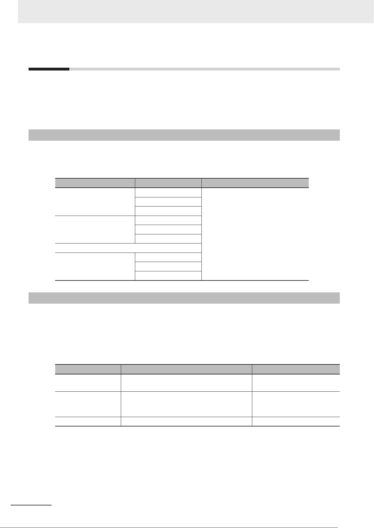
3 Robot Control Parameters
3-2
3-2-1
Robot Common Parameters
The robot common parameters provide settings that are required for OMRON robots to the RC Func-
tion Module.
Even if more than one OMRON robot is connected to the Robot Integrated CPU Unit, there is only one
set of robot common parameters per Robot Integrated CPU Unit.
Robot Common Parameters
Use the Sysmac Studio to set the robot common parameters for each Robot Integrated CPU Unit.
Refer to the Sysmac Studio Robot Integrated System Building Function with Robot Integrated CPU
Unit Operation Manual (Cat. No. W595) for details on how to set the robot common parameters.
Classification Parameter name Reference
I/O Control Setting 1 Signal Number 3-2-2 I/O Control Settings on page
Device
Port
I/O Control Setting 2 Signal Number
Device
Port
⁞ (Each element above can be repeated up to 999 times)
I/O Control Setting 999
Signal Number
Device
Port
3-4
3-2-2
I/O Control Settings
Make the I/O Control Settings to use I/O ports of the EtherCAT slave devices that are connected to
the Robot Integrated CPU Unit and NX Units on the EtherCAT Coupler Unit as I/O signals in the V+
program.
Refer to the Sysmac Studio Robot Integrated System Building Function with Robot Integrated CPU
Unit Operation Manual (Cat. No. W595) for how to set the I/O control settings.
Parameter name Function Setting range
Signal Number Set the signal number that is used when a device
is accessed from the V+ program.
Device Select an EtherCAT slave device or an NX Unit on
the EtherCA
signal number
Port Select the port to assign to the signal number. ---
The images of the setting tab pages are shown below.
The following figures are the setting tab pages for I/O Map (upper figure) and Robot Common Settings
(lower figure).
T Coupler Unit that is assigned to the
.
4001 to 4999
---
3-4
NJ-series Robot Integrated CPU Unit User's Manual (O037)
Page 77

PLC Function
Module
EtherCAT
input slave
Input port 1
*1
Input port 2
N
X
Output Unit
Output port 1
Output port 2
*1
Robot Control
Function Module
V+ program
Signal number 4001
Signal number 4999
Signal input
*2
Signal output
*2
⁞
⁞
⁞
3 Robot Control Parameters
3-2 Robot Common Parameters
3
3-2-2 I/O Control Settings
The following figure shows an overview of I/O control settings.
In an example below, the port 1 of input slave in the EtherCA
number 4001. The port 2 of the Digital Output Unit in NX Units on the EtherCAT Coupler Unit is as-
signed to the signal number 4999.
*1. Assign to an EtherCAT slave device or an NX Unit on the EtherCAT Coupler Unit.
*2. Can be used from the V+ program in the same way as the robot built-in I/O.
Precautions for Correct Use
• Device variables cannot be assigned in the I/O Map for output ports to which the signal numbers are assigned in the I/O Control Settings. Therefore, the output ports to which the signal
numbers are assigned cannot output signals from the sequence control program.
The signal numbers can be assigned in the I/O Control Settings for the output ports that are
assigned to the device variables in the I/O Map. In this case, the device variables in the I/O
Map are cleared (not assigned). Therefore, the output ports that are assigned to the device
variables cannot output signals from the V+ program.
NJ-series Robot Integrated CPU Unit User's Manual (O037)
•
Device variables can be assigned for input ports to which the signal numbers are assigned in
the I/O Control Settings. Therefore, the input ports to which the signal numbers are assigned
can be accessed in the sequence control program.
T slave device is assigned to the signal
3-5
Page 78

3 Robot Control Parameters
Signal Number
Set the signal number when the digital I/O of the EtherCAT slave devices or the NX Units on the Ether-
CAT Coupler Unit is accessed from the V+ program.
In the V+ program, all I/O ports are assigned to signal numbers and any signal is input or output by
specifying its signal number
For the input ports or output ports of a device connected to the Robot Integrated CPU Unit, you can
assign signal numbers between 4001 and 4999 in the V+ program.
Device
Select the device to assign to the signal number.
The following table shows the EtherCAT slave device and NX Units that can be selected.
Device Type
EtherCAT slave Digital I/O
NX Units NX Unit with input refreshing with input changed times
Digital Input Unit
NX Unit with output refreshing with specified time stamps
Digital Output Unit
Digital Mixed I/O Unit
.
Precautions for Correct Use
You cannot specify CJ-series Units that are connected to the Robot Integrated CPU Unit.
Port
Select the port corresponding to the signal number.
Select a port on the device that you selected in Device on page 3-6.
3-6
NJ-series Robot Integrated CPU Unit User's Manual (O037)
Page 79

3 Robot Control Parameters
3-3
3-3-1
3-3-2
Robot Setting Parameters
The robot setting parameters provide settings for OMRON robots controlled in the RC Function Mod-
ule.
There are robot setting parameters for each OMRON robot to control.
Robot Setting Parameters
Use the Sysmac Studio to set the robot setting parameters for each OMRON robot.
Refer to the Sysmac Studio Robot Integrated System Building Function with Robot Integrated CPU
Unit Operation Manual (Cat. No. W595) for details on how to set the robot setting parameters.
Classification Parameter name Reference
Robot Basic Settings Robot Number 3-3-2 Robot Basic Settings on page 3-
Robot Device Assignment
Robot Basic Settings
Set the selection of the EtherCAT slave device for the OMRON robot.
7
3-3 Robot Setting Parameters
3
3-3-1 Robot Setting Parameters
Parameter name Function Setting range Default
Robot Number
Robot Device Assignment Select the EtherCAT slave device corresponding to the
*1. You cannot change the robot number.
*2. The OMRON robot that is not assigned, among the OMRON robots that exist on the EtherCAT, can be set.
*1
Set the number that is used when a OMRON robot is accessed from the V+ program.
OMRON robot.
1 to 8 1
*2
---
Robot Number
The robot numbers are automatically set in the order that the OMRON robots are created, and you
cannot change the numbers.
Refer to Robot Variables on page 2-
and _RC_RBT[0] to _RC_RBT[7], the robot variable names in the system-defined variables.
Also, refer to Robot I/O Variables on page 2-10 for information on the relationship between the robot
numbers and _RC_RBT_IO[0] to _RC_RBT_IO[7], the robot I/O variable names in the system-defined
variables.
9 for information on the relationship between the robot numbers
Robot Device Assignment
Select the EtherCAT slave device corresponding to the OMRON robot.
NJ-series Robot Integrated CPU Unit User's Manual (O037)
3-7
Page 80

3 Robot Control Parameters
3-8
NJ-series Robot Integrated CPU Unit User's Manual (O037)
Page 81

4
Program Design of Robot Control
This section describes the program design of the robot control.
4
4-1 Introduction
4-2 Sequence Control Program........................................................................... 4-3
4-2-1 Robot Control Instructions............................................................................... 4-3
4-2-2 Timing Charts for Robot Control Instructions .................................................. 4-3
4-2-3 System-defined Variables for Robot Control ................................................... 4-6
4-2-4 Execution Control for V+ Program................................................................... 4-6
4-2-5 Shared Variables with V+ Program ................................................................. 4-7
4-2-6 Using Shared Variables with V+ Programs ....................................................4-11
4-3 V+ Program ................................................................................................... 4-14
4-3-1 Overview of V+ Programs ............................................................................. 4-14
4-3-2 Control of V+ Tasks ....................................................................................... 4-14
4-3-3 I/O Control Settings for V+ Program.............................................................. 4-14
4-4 Debugging Program..................................................................................... 4-16
4-4-1 Offline Debugging.......................................................................................... 4-16
4-4-2 Transferring Settings and Programs.............................................................. 4-17
4-4-3 Online Debugging.......................................................................................... 4-17
4-5 States and State Transition......................................................................... 4-19
4-5-1 States of the Robot Integrated CPU Unit ...................................................... 4-19
4-5-2 States of the OMRON Robots ....................................................................... 4-20
4-5-3 Changing the Operating Mode ...................................................................... 4-23
4-5-4 Operation of Events....................................................................................... 4-24
.................................................................................................... 4-2
NJ-series Robot Integrated CPU Unit User's Manual (O037)
4-1
Page 82

4 Program Design of Robot Control
4-1
Introduction
The Robot Integrated CPU Unit can perform robot control, in addition to sequence control and motion
control.
There are two methods of robot control as described below.
• Write robot control instructions in a sequence control program to perform robot control.
Outputs from robot control instructions and system-defined variables for robot control are refreshed
in the same control period as that of I/O control or motion control.
This method is suitable for controlling an OMRON robot with other devices.
• Write a V+ program and execute it to perform robot control.
The V+ language provides more functions related to the robot control than robot control instructions
of the sequence control program.
In addition, because V+ programs are executed line by line, it is easy to write a sequence of OM-
RON robot motions.
This method is suitable mainly for programming OMRON robot motions.
Moreover, you can start and stop program execution and share variables between a sequence control
program and a V+ program.
4-2
NJ-series Robot Integrated CPU Unit User's Manual (O037)
Page 83

4 Program Design of Robot Control
4-2
4-2-1
Sequence Control Program
To control a robot from a sequence control program, use robot control instructions defined as function
blocks.
Robot control instructions are also used to start and stop execution of a V+ Task.
In addition, to read information from the OMRON robot and control the robot built-in I/O, use system-
defined variables for robot control defined as system-defined variables.
It is possible to share the interlock and variable values between the programs using the shared varia-
bles between a sequence control program and a V+ program.
Robot Control Instructions
The following table lists robot control instructions.
Type Function
Common commands Instructions to start/abort the V+ Task execution and read status information
Instructions to convert a coordinate system for use with NJ Robotics functions
Robot commands Instructions to directly control the OMRON robot
4-2 Sequence Control Program
4
4-2-1 Robot Control Instructions
4-2-2
Refer to Section 6 Robot Control Instructions on page
tions.
In addition, the following system control instructions are used to reset errors and read status informa-
tion from the RC Function Module.
Type Function
System control instructions Instructions to reset all current errors from the RC Function Module
Instructions to read the highest level current errors from the RC Function Module
Refer to Section 10 System Control Instructions on page 10-
structions.
6-1 for details on the robot control instruc-
1 for details on the system control in-
Timing Charts for Robot Control Instructions
This section describes the basic timing charts for the robot control instructions.
Refer to the individual instruction for details on the unique input variables and output variables for
each instruction.
Execute-type Instructions
The instruction starts when Execute changes to TRUE.
Busy (Executing) changes to TRUE when the instruction is acknowledged.
If the processing is completed normally, Busy
The processing completed normally means that the command from the instruction to RC Function
Module is completed.
NJ-series Robot Integrated CPU Unit User's Manual (O037)
changes to FALSE and Done changes to TRUE.
4-3
Page 84

Execute
Done
Busy
CommandAborted
Error
ErrorID
16#00
00
Execute
Done
Busy
CommandAborted
Error
ErrorID
16#00
00
4 Program Design of Robot Control
If the same instances of instructions are executed consecutively, wait for more than one task period
after Done for previous execution changes to FALSE, and then Execute
TRUE.
If the processing is interrupted, Busy changes to FALSE.
For the instructions with CommandAborted output variable, CommandAborted changes to TRUE at
the same time.
When an error occurs, Error changes to TRUE and Busy changes to FALSE.
If either Done or CommandAborted changes to TRUE while Execute is TRUE, both Done and
CommandAborted change to FALSE when Execute changes to FALSE.
If Done and CommandAborted change to TRUE while Execute is FALSE, both Done and
CommandAborted change to TRUE for one task period.
When an error occurs, the error code for ErrorID (Error Code) is set.
The Error and ErrorID (Error Code) are retained after Execute changes to FALSE. When the error is
reset, Error changes to FALSE and 16#0000 is set in ErrorID (Error Code).
for next instruction changes to
When the Instruction Ended Normally
When the Instruction is Aborted
4-4
NJ-series Robot Integrated CPU Unit User's Manual (O037)
Page 85

Busy
Done
CommandAborted
Error
16#0000
ErrorID
Execute
ErrorID
Busy
Valid
Enable
Error
ErrorID
16#0000
Eable
Busy
Valid
Error
ErrorID
16#0000 ErrorID
4 Program Design of Robot Control
When an Error Occurred
Enable-type Instructions
The instruction is executed while Enable is TRUE.
When the instruction is acknowledged, Busy (Executing) changes to TRUE, and then Valid
changes to TRUE while output value is calculated.
4-2 Sequence Control Program
(Enabled)
4
When an error occurs, Error changes to TRUE and Busy (Executing) and Valid change to FALSE.
Even if Enable changes from TRUE to FALSE, Error remains TRUE.
When an error occurs, the error code for ErrorID (Error Code) is set.
When Error changes from TRUE to FALSE, 16#0000 is set in ErrorID (Error Code).
When the Instruction Ended Normally
When an Error Occurred
4-2-2 Timing Charts for Robot Control Instructions
NJ-series Robot Integrated CPU Unit User's Manual (O037)
4-5
Page 86

4 Program Design of Robot Control
4-2-3
4-2-4
System-defined Variables for Robot Control
The following table lists system-defined variables for robot control.
Each of these variables is updated at a frequency of the control period of primary periodic task for the
Robot Integrated CPU Unit
Variable Function
Robot control common variable
Robot variables Monitor the status of each OMRON robot.
Robot I/O variables Monitor the built-in I/O of each OMRON robot.
Refer to 2-4 System-defined Variables for Robot Control on page
.
Monitors the common status of the RC Function Module.
Monitor the actual position of the TCP and the actual position of the joint for
each OMRON robot.
Output to the output port of the built-in I/O of each OMRON robot.
2-8 for details on each variable.
Execution Control for V+ Program
You can execute robot control instructions in a sequence control program to execute V+ tasks to which
V+ programs are assigned.
You can also assign V+ programs to V+ tasks to use V+ programs that are written with OMRON robot
motions as subroutines in a sequence control program.
Y
ou can also use robot control instructions to obtain the status of a V+ task or abort execution of a V+
task.
V+ Task Control from Sequence Control Program
This section describes the V+ task control from the sequence control program in the Robot Integrated
CPU Unit.
You can control the following V+ tasks from a sequence control program. Refer to S
and Instructions on page 7-1 for details on each instruction.
Function Description Instruction Reference
Execute V+ Task Starts execution of the specified V+ task. RC_ExecVpPrgTask page 8-2
Abort V+ Task Aborts execution of the specified V+ task. RC_AbortVpPrgTask page 8-6
Get V+ Task Status Reads the specified V+ task status. RC_GetVpPrgTaskStatus page 8-8
ection 7 Variables
4-6
NJ-series Robot Integrated CPU Unit User's Manual (O037)
Page 87

Sequence
control program
V+ task
RC_ExecVpPrgTask
1 PROGRAM
2
3 ENABLE POWER
4 SELECT ROBOT=1
5 ATTACH ROBOT
6
7 (Shared variable)=TRUE
8
Start V+ tasks
Check the execution
status of V+ tasks
Abort V+ tasks
Read and
write a
shared
variable
(Shared variable)
Shared variable
RC_GetVpPrgTaskStatus
RC_AbortVpPrgTask
4 Program Design of Robot Control
4-2 Sequence Control Program
Starting V+ Tasks
The sequence control program executes the RC_ExecVpPrgTask (Execute V+ Task) instruction to
start execution of a V+ task.
Refer to RC_ExecVpPrgT
Aborting V+ Tasks
The sequence control program executes the RC_AbortVpPrgTask (Abort V+ Task) instruction to re-
quest to abort a V+ task.
Refer to RC_AbortVpPrgTask on page 8-6 for details on the instruction.
Checking Execution Status of V+ Tasks
The sequence control program executes the RC_GetVpPrgTaskStatus (Get V+ Task Status) in-
struction to check execution status of a V+ task.
4-2-5
Refer to RC_GetVpPrgTaskStatus on page 8-8 for details on the instruction.
Shared Variables with V+ Program
You can share variables that you defined in a sequence control program with a V+ program.
The shared variables can be read and written from both the sequence control program and the V+ pro-
gram.
This allows you to exchange information and synchronize the timing of processing between the se-
quence control program and V+ program in execution.
ask on page 8-2
4
4-2-5 Shared Variables with V+ Program
for details on the instruction.
NJ-series Robot Integrated CPU Unit User's Manual (O037)
o share a variable, you need to define it as a global variable in the global variable table of the Sys-
T
mac Studio. Then, you can define the variable with the same name in the V+ program as the EXTER-
NAL variable to share it.
Since, as entity
an external variable.
, the variable is a global variable, the V+ program accesses and updates its value as
4-7
Page 88

Sequence control program
V+ program
Sharable
Not sharable
Global variables
*1
Local variables
EXTERNAL variables
AUTO variables
LOCAL variables
GLOBAL variables
*2
*3
Sequence control program
Used as a flag
IF NOT gisupdated THEN
gsharedvar[1]: = var1;
gsharedvar[2]: = var2;
gisupdated: = TRUE;
END_IF;
V+ program
EXTERNAL gsharedvar[]
EXTERNAL gisupdated
LOCAL var1, var2
IF gisupdated THEN
var1=gsharedvar[1]
var2=gsharedvar[2]
gisupdated=FALSE
END
Global variables
Array[0..10] OF LREAL
BOOL
gsharedvar
gisupdated
4 Program Design of Robot Control
You cannot share variables that are not mentioned above. The mechanism of shared variables is giv-
en below.
*1. The system-defined variables cannot share among global variables.
*2. Reading a value: Access to an external variable with the same name
*3. Writing a value: Update of an external variable with the same name
Refer to the eV+3 User's Manual (Cat. No. I651) and the eV+3 Keyword Reference Manual (Cat. No.
I652) for information on the EXTERNAL variable.
Additional Information
A variable name in the V+ program can be used with lowercase letters only.
A variable name in the sequence control program can be used with uppercase and lowercase
letters. However, it is not case sensitive.
Therefore, even if the global variable name that is defined in the sequence control program includes uppercase letters, the variable can be shared with the variable, whose name is used
with lowercase letters, in the V+ program.
Concurrency of Shared Variables
The concurrency of variable values is not ensured if more than one shared variable is read or write
continuously in the V+ program.
To ensure concurrency
write data.
Example: When values of array variables are accessed by a V+ program with concurrency maintained
, create a separate flag as a shared variable to control the timing to read and
4-8
NJ-series Robot Integrated CPU Unit User's Manual (O037)
Page 89

4 Program Design of Robot Control
Data Type of Shared Variables
The shared variables have sharable or not sharable data type.
The following table gives whether a variable is sharable or not depending on the data type. Be sure to
check that the variable data is within the valid range. Exceeding the valid range results in an undefined
value.
(¡: Sharable, ---: Not sharable)
4-2 Sequence Control Program
Basic data
types
Data type Data size
BOOL 16 bits
BYTE 8 bits ---
WORD 16 bits ---
DWORD 32 bits ---
LWORD 64 bits ---
SINT 8 bits ---
INT 16 bits
DINT 32 bits ---
LINT 64 bits ---
USINT 8 bits ---
UINT 16 bits
UDINT 32 bits ---
ULINT 64 bits ---
REAL 32 bits
LREAL 64 bits
TIME 64 bits ---
DATE 64 bits ---
TIME_OF_DAY 64 bits ---
DATE_AND_TIME64 bits
Sharable or
not
¡
¡
¡
¡
¡
---
Remarks
Valid range of data: -32768 to 32767
Valid range of data: 0 to 65535
Valid range of data: -3.402823 × 10
to 3.402823 × 10
(7 significant digits)
Valid range of data:
-1.79769313486231 × 10
1.79769313486231 × 10
(15 significant digits)
38
308
308
to
4
4-2-5 Shared Variables with V+ Program
38
STRING Number of sin-
gle-byte characters × 8 bits
Other data
types
NJ-series Robot Integrated CPU Unit User's Manual (O037)
Structure ---
Union --- ---
Enumeration --- ---
Fixed length array
Number of elements × Data
size of basic data
type
---
---
¡
A variable can be shared if all of the
following conditions are met.
• Basic data type is sharable
• One-dimensional array only
• Array with 100 elements or less
4-9
Page 90

Sequence control program
Data type conversion instruction
gsharedvardint: =var1;
gsharedvarlreal: =
DINT_TO_LREAL(gsharedvardint);
V+ program
EXTERNAL gsharedvarlreal
IF gsharedvarlreal==0 THEN
...
Global variables
DINT
LREAL
gsharedvardint
gsharedvarlreal
4 Program Design of Robot Control
You can use the Data type conversion instructions in the sequence control program to share variables
of data types that cannot be shared.
To share a DINT variable, for example, use the DINT_T
so the variable can be shared. Note that the Data type conversion instructions have specific valid
ranges for both the data types before and after conversion. Check the specifications of the Data type
conversion instruction that you use before use.
Refer to Data Type Conversion Instructions in the NJ/NX-series Instructions Reference Manual (Cat.
No. W502) for details on the Data type conversion instruction.
For shared variables, a V+ Program Error (96040000 hex) will occur in the following cases.
• A variable that is not defined in the sequence control program is accessed from the V+ program.
• A variable defined with the data type that cannot be shared is accessed from the V+ program.
• An attempt was made to write the variable that is declared as Read Only in the sequence control
program from the V+ program.
• A subscript (index) for an array is within the range defined in the V+ program, but it is out of range
defined in the sequence control program.
• A subscript (index) that is out of range of which the array is declared in the sequence control pro-
gram is accessed from the V+ program.
For example, for the array that ARRAY[10..100] is declared in the sequence control program, ac-
cess to ARRAY[0] in the V+ program.
O_REAL instruction to convert it to REAL data,
If Data Type That Cannot be Shared was Defined as EXTERNAL Variable
If the global variable is declared with a data type that cannot be shared and you define it as an
EXTERNAL variable in the V+ program, a system event will occur during execution of the V+ pro-
gram. In this case, it does not affect other function modules and execution of the sequence control
program.
When you share variables of data types that cannot be shared, use the Data type conversion in-
structions in the sequence control program to convert to variables of data types that can be shared.
Example: When the value of a DINT variable is accessed by a V+ program
Deleting Shared Variables
When you delete a shared variable after you set the variable to be shared, delete both the global vari-
4-10
able and the EXTERNAL declaration.
NJ-series Robot Integrated CPU Unit User's Manual (O037)
Page 91
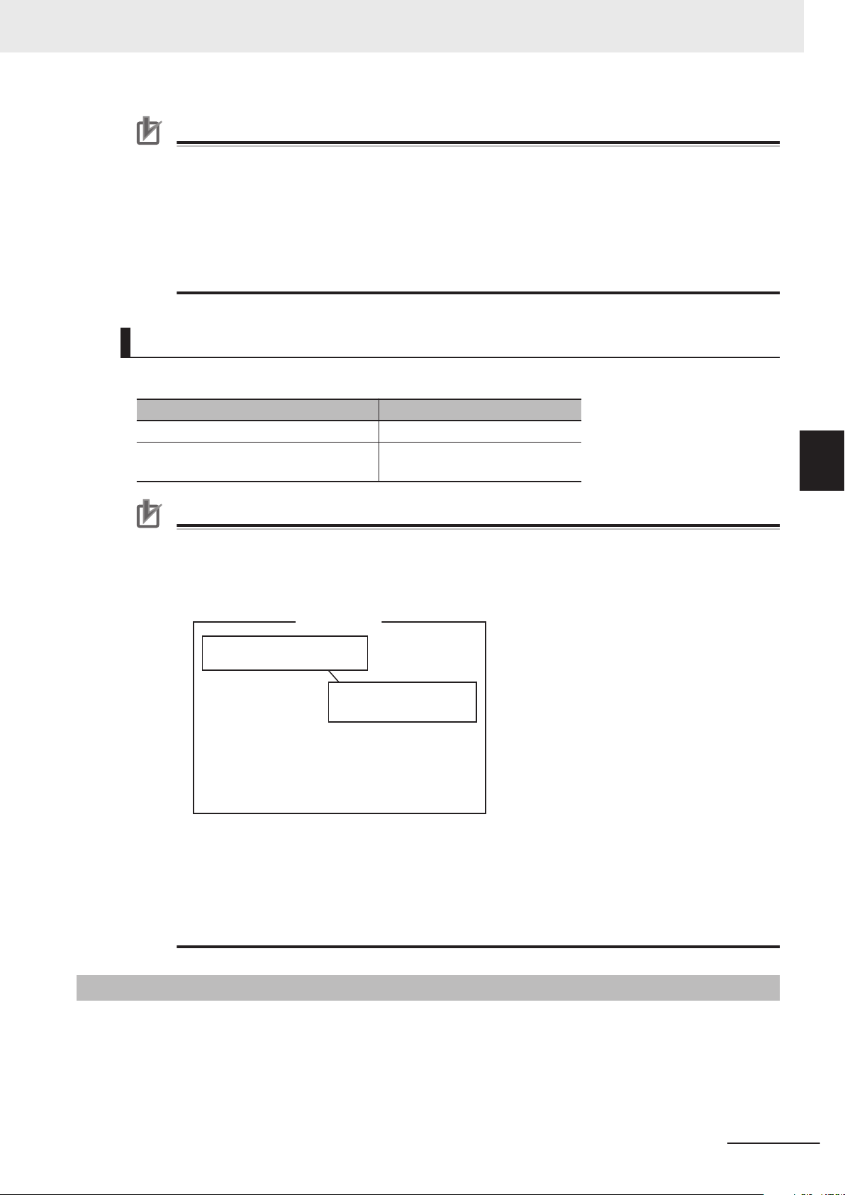
V+ program
EXTERNAL gprogramstate
GLOBAL gprogramstate
gprogramstep=0
WHILE TRUE DO
IF (gprogramstep==1) THEN
MOVE p1
gprogramstep=2
END
END
A variable with the same
name already exists.
*1
4 Program Design of Robot Control
Precautions for Correct Use
• If you delete only the global variable, a system event will occur when the EXTERNAL variable
is defined during execution of the V+ program.
• If you delete only the EXTERNAL declaration, the global variable can be used only in the sequence control program.
In addition, the variable is used for an independent variable that is not related in the global
variable within the V+ program.
In other words, the variables with the same variable name are used as dif
ferent variables in-
dividually in the sequence control program and in the V+ program.
Restrictions on Variable Names of Shared Variables
The variable names of shared variables are subject to the following restrictions.
Item Restriction
Maximum length of variable name 15 characters
Applicable characters for variable names 0 to 9, a to z, ".", and ","
The first character must be a to z.
4-2 Sequence Control Program
4
Precautions for Correct Use
• If you define the EXTERNAL variable in the V+ program, do not define a variable with the
same name as the AUTO, LOCAL, or GLOBAL variable in the same V+ program.
When the same name as the EXTERNAL variable is defined, a system event occurs in the
RC Function Module.
*1. A system event occurs.
•
If you define the EXTERNAL variable in the V+ program, define a variable with the same
name in the global variable table of the sequence control program.
When a variable with the same name does not exist in the global variable table of the sequence control program, a system event occurs in the RC Function Module.
This does not af
fect other function modules and execution of the sequence control program.
4-2-6 Using Shared Variables with V+ Programs
4-2-6
NJ-series Robot Integrated CPU Unit User's Manual (O037)
This section describes how to use the shared variables that share variables between a sequence con-
trol program and a V+ program.
Using Shared Variables with V+ Programs
4-11
Page 92

Sequence control program
IF(E001_In_Bit00=TRUE) THEN
// Interlock
gsensoron: =TRUE;
END_IF;
V+ program
EXTERNAL gsensoron
gsensoron=FALSE
WHILE TRUE DO
; Interlock
IF gsensoron THEN
MOVE p1
gsensoron=FALSE
END
Sequence control program
CASE (gprogramstep) OF
0:
// Initialize
gprogramstep: =1;
1:
// Wait Robot
2:
// Finalize
gprogramstep: =3;
END_CASE;
V+ program
EXTERNAL gprogramstep
gprogramstep=0
WHILE TRUE DO
IF (gprogramstep==1) THEN
MOVE p1
gprogramstep=2
END
END
4 Program Design of Robot Control
Using Shared Variables
The methods to share variables between a sequence control program and a V+ program are descri-
bed below.
•
Synchronizing the control timing with interlock between programs
• Controlling the processing sequence by sharing values of variables between programs
Synchronizing the Control Timing with Interlock Between Programs
You can use the shared variables if a sensor input is detected with a sequence control program and
the V+ program operation is started.
An example of a program is provided below.
In this example, when data E001_In_Bit00, which has been input to bit 0 of the Digital Input Unit
(EtherCAT slave), turns ON in the sequence control program, the value of shared variable
gsensoron changes to TRUE. Then, the V+ program starts control operation.
Controlling the Processing Sequence by Sharing Values of Variables Be-
tween Programs
The values of variables can be shared between a sequence control program and a V+ program.
This allows you to control the sequence of processing in each process.
An example of a program is provided below.
4-12
NJ-series Robot Integrated CPU Unit User's Manual (O037)
Page 93

4 Program Design of Robot Control
Shared Variable Setting Procedure
The variable to share is registered in the global variable table of the sequence control program. Then,
you can use variables by sharing them when you make the EXTERNAL declaration to a variable with
the same name in the V+ program.
4-2 Sequence Control Program
4
4-2-6 Using Shared Variables with V+ Programs
NJ-series Robot Integrated CPU Unit User's Manual (O037)
4-13
Page 94

4 Program Design of Robot Control
4-3
4-3-1
V+ Program
A control program that is written in the V+ language is called V+ program.
The Robot Integrated CPU Unit executes V+ programs to assign to V+ tasks.
It is also possible to control the OMRON robots only with V+ programs.
This section provides information related to the V+ program in the Robot Integrated CPU Unit.
Refer to the eV+3 User's Manual (Cat. No. I651) and the eV+3 Keyword Reference Manual (Cat. No.
I652) for details on the descriptions in V+ language.
Refer to the Sysmac Studio Robot Integrated System Building Function with Robot Integrated CPU
Unit Operation Manual (Cat. No. W595) for how to assign V+ programs to V+ Tasks.
Overview of V+ Programs
The Robot Integrated CPU Unit can start or stop V+ tasks from a sequence control program, a V+ pro-
gram, or the Sysmac Studio.
The RC Function Module analyzes the V+ program assigned to V+ tasks line by line and sends in-
structions (V+ keywords) and command values to the OMRON robot connected to the EtherCAT net-
work.
After receipt of an instruction (V+ keyword) or a command value, the OMRON robot performs path cal-
culation and controls the robot arm. The present value and status of the OMRON robot are sent
through the EtherCAT network to the RC Function Module.
It is possible to share the interlock and variable values between the programs using the shared varia-
bles between a sequence control program and a V+ program.
4-3-2
4-3-3
V+ programs can automatically start when the power supply to the Robot Integrated CPU Unit is
turned ON.
You can control the OMRON robots only with V+ programs using the automatic start.
Refer to the eV+3 User's Manual (Cat. No. I651) and the eV+3 Keyword Reference Manual (Cat. No.
I652) for details on the automatic start function.
Control of V+ Tasks
Refer to the eV+3 User's Manual (Cat. No. I651) and the eV+3 Keyword Reference Manual (Cat. No.
I652) for how to control V+ Tasks with V+ programs.
I/O Control Settings for V+ Program
To perform digital I/O control for the EtherCAT slave devices or the NX Units on the EtherCAT Coupler
Unit in the V+ program, you need to make the settings in the Robot Common Parameter Settings Tab
Page on the Sysmac Studio.
Refer to 3-2-2 I/O Control Settings on page 3-4 for details on the I/O control settings.
4-14
NJ-series Robot Integrated CPU Unit User's Manual (O037)
Page 95

4 Program Design of Robot Control
Precautions for Correct Use
If the digital I/O control is performed for the EtherCAT slave devices that are not OMRON robots
or the NX Units on the EtherCAT Coupler Unit in the V+ program, confirm that the
_EC_PDSlavTbl (Process Data Communicating Slave T
to TRUE in the sequence control program.
Confirm that the process data communications of the EtherCAT slaves is enabled before the
digital I/O control is performed for the EtherCAT slave devices or the NX Units on the EtherCAT
Coupler Unit in the V+ program.
able) system-defined variable changes
4-3 V+ Program
4
4-3-3 I/O Control Settings for V+ Program
NJ-series Robot Integrated CPU Unit User's Manual (O037)
4-15
Page 96

Online editing
Pull
V+ Edit
Push
V+ program
SD Memory Card
Robot setting files
Virtual NJ501-R£££
Sysmac Studio
Main memory
V+ program
Non-volatile memory
4 Program Design of Robot Control
4-4
4-4-1
Debugging Program
This section describes the offline debugging from the simulation operation and the online debugging
from the online connection.
The simulation operation for the Robot Integrated CPU Unit can be performed only in EMULATION
mode.
Refer to the NJ/NX-series CPU Unit Software User’s Manual (Cat. No. W501) for information on the
offline debugging in the sequence control program.
Offline Debugging
This section describes the offline debugging from the simulation operation.
When the simulation operation starts, the V+ emulator is executed on the Sysmac Studio.
When the Sysmac Studio connects to the V+ emulator, the following operations are possible.
4-16
Function Description
Online editing Edits directly to the sequence control program in the built-in non-volatile memory.
V+ Edit Edits directly to the V+ program in the main memory.
Push to V+ memory Transfers the V+ program on the Sysmac Studio to the main memory.
Pull from V+ memory Transfers the V+ program in the main memory to the Sysmac Studio.
Check V+ memory Compares the V+ program in the main memory and the V+ program on the Sysmac Stu-
The simulation operation for the Robot Integrated CPU Unit can be performed only in EMULATION
mode.
If the EMULATION mode is started, click the Enable/Disable EMULA
on the main window.
dio.
TION mode icon in the toolbar
NJ-series Robot Integrated CPU Unit User's Manual (O037)
Page 97

4-4-2
Download Upload
Non-volatile memory
V+ program
Main memory
Sysmac Studio
NJ501-R£££
Robot setting files
SD Memory Card
Upload
Download
V+ program
4 Program Design of Robot Control
Refer to the Sysmac Studio Robot Integrated System Building Function with Robot Integrated CPU
Unit Operation Manual (Cat. No. W595) and the Sysmac Studio 3D Simulation Function Operation
Manual (Cat. No. W618) for details on the simulation.
Precautions for Correct Use
V+ Edit is disabled during execution of V+ program. Stop the V+ program before executing the
V+ Edit.
Transferring Settings and Programs
This section explains the functionality to transfer the settings and programs between the Sysmac Stu-
dio and the built-in non-volatile memory in the
Robot Integrated CPU Unit
When the Sysmac Studio connects online to the Robot Integrated CPU Unit, the following operations
are possible.
or SD Memory Card.
4-4 Debugging Program
Function Description
Downloading data Transfers the settings and programs from the Sysmac Studio to the built-in non-volatile
Uploading data Transfers the settings and programs from the built-in non-volatile memory in the Robot Inte-
Verifying data Compares the settings and programs between the built-in non-volatile memory in the Robot
Refer to the NJ/NX-series CPU Unit Software User’
downloading and uploading data.
4-4-3
Online Debugging
4
4-4-2 Transferring Settings and Programs
memory in the Robot Integrated CPU Unit or SD Memory Card.
grated CPU Unit or SD Memory Card to the Sysmac Studio.
Integrated CPU Unit or SD Memory Card and the Sysmac Studio.
s Manual (Cat. No. W501) for information on the
This section describes the online debugging.
NJ-series Robot Integrated CPU Unit User's Manual (O037)
4-17
Page 98

Online editing
Pull
V+ Edit
Push
V+ program
SD Memory Card
Robot setting files
NJ501-R£££
Main memory
Sysmac Studio
V+ program
Non-volatile memory
4 Program Design of Robot Control
When the Sysmac Studio connects online to the Robot Integrated CPU Unit, the following operations
are possible.
Function Description
Online editing Edits directly to the sequence control program in the built-in non-volatile memory.
V+ Edit
Push to V+ memory Transfers the V+ program on the Sysmac Studio to the main memory.
Pull from V+ memory Transfers the V+ program in the main memory to the Sysmac Studio.
Check V+ memory Compares the V+ program in the main memory and the V+ program on the Sysmac Stu-
*1. When you perform online debugging, set V+ Edit Mode to Start in the Sysmac Studio and the V+ Program
Editor Tab Page can be edited.
The online connection to the
Edits directly to the V+ program in the main memory.
dio.
Robot Integrated CPU Unit is not possible in EMULATION mode.
Refer to the Sysmac Studio Version 1 Operation Manual (Cat. No. W504) and the
*1
Sysmac Studio
Robot Integrated System Building Function with Robot Integrated CPU Unit Operation Manual (Cat.
No. W595) for details on the online connection.
Precautions for Correct Use
• The settings are required to save the V+ program in the SD Memory Card.
Refer to the Sysmac Studio Robot Integrated System Building Function with Robot Integrated
CPU Unit Operation Manual (Cat. No. W595) for details on the save settings.
•
V+ Edit is disabled during execution of V+ program. Stop the V+ program before executing
the V+ Edit.
Unintended operation may occur for the online editing in the robot control instruction. Confirm
•
safety before use.
4-18
NJ-series Robot Integrated CPU Unit User's Manual (O037)
Page 99

4 Program Design of Robot Control
4-5
4-5-1
States and State Transition
This section describes the states and state transition of the Robot Integrated CPU Unit and OMRON
robots.
States of the Robot Integrated CPU Unit
This section describes the operation for states of the Robot Integrated CPU Unit when the operating
mode of the OMRON robot is in Auto mode.
Refer to Operating Mode of the OMRON Robot on page 4-21 for information on operating mode of
the OMRON robot.
Refer to CPU Unit Status in the NJ/NX-series CPU Unit Software User’s Manual (Cat. No. W501) for
information on each state of the CPU Unit.
Precautions for Correct Use
If the operating mode of the Robot Integrated CPU Unit is changed to PROGRAM mode, the
operations and control for the OMRON robot that is controlled with V+ program and I/O continue.
The devices that are controlled with the sequence control program and other robots stop. Always confirm safety before you change the operating mode to prevent interference between devices.
4-5 States and State Transition
4
4-5-1 States of the Robot Integrated CPU Unit
Operations in Sequence Control Program
The sequence control program is executed in RUN mode.
If there are no errors in the RC Function Module, the control for all of OMRON robots attached from
the sequence control program and inputs to and outputs from the robot built-in I/O are possible.
Even if an error occurred in the RC Function Module, the execution of the sequence control program
continues.
Differences in Event Levels
The operation differs depending on the event level that occurs in the RC Function Module as de-
scribed below.
• If a partial fault level error occurs in the RC Function Module, the control for all of OMRON robots
and inputs to and outputs from the robot built-in I/O are not possible.
• If a minor fault level error that "robot" is given for the source details occurs in the RC Function
Module, the control for the OMRON robot and outputs from the robot built-in I/O are not possible.
Only inputs to the robot built-in I/O are possible.
• If an observation or information occurs in the RC Function Module, the control for all of OMRON
robots attached from the sequence control program including the OMRON robot and inputs to
and outputs from the robot built-in I/O are possible.
The operation when the control for the OMRON robots and inputs to and outputs from the built-in
I/O are not possible depends on the specifications of OMRON robot. Refer to the OMRON robot
manuals for details.
NJ-series Robot Integrated CPU Unit User's Manual (O037)
4-19
Page 100

4 Program Design of Robot Control
Refer to the NJ/NX-series CPU Unit Software User’
series CPU Unit Built-in EtherCAT Port User’s Manual (Cat. No. W505) for information on the
EtherCAT slaves that are not OMRON robots.
s Manual (Cat. No. W501) and the NJ/NX-
Operations in V+ Program
The V+ programs are executed in both RUN mode and PROGRAM mode.
The OMRON robot continues to move when the operating mode changes from RUN mode to PRO-
GRAM mode.
If there are no errors in the RC Function Module, the control for the OMRON robots attached from the
V+ program and inputs to and outputs from the robot built-in I/O are possible.
Differences in Event Levels
The operation differs depending on the event level that occurs in the RC Function Module as de-
scribed below.
•
If a partial fault level error occurs in the RC Function Module, all of V+ programs stop.
The control for all of OMRON robots and inputs to and outputs from the robot built-in I/O are not
possible.
• If a minor fault level error occurs in the RC Function Module, the operation continues for the V+
programs.
Therefore, the control for the OMRON robot and inputs to and outputs from the robot built-in I/O
are possible.
• If an observation level error or an information level error that is not V+ Program Error (96040000
hex) occurs in the RC Function Module, the operation continues for the V+ programs.
Therefore, the control for the OMRON robot and inputs to and outputs from the robot built-in I/O
are possible.
• If the V+ Program Error (96040000 hex) in an information level occurs, the V+ program in which
the OMRON robot is attached stops.
Therefore, the control for the OMRON robot and inputs to and outputs from the robot built-in I/O
are not possible.
4-5-2
4-20
The operation when the control for the OMRON robots and inputs to and outputs from the built-in
I/O are not possible depends on the specifications of OMRON robot. Refer to the OMRON robot
manuals for details.
Refer to the NJ/NX-series CPU Unit Software User’s Manual (Cat. No. W501) and the NJ/NX-
series CPU Unit Built-in EtherCAT Port User’s Manual (Cat. No. W505) for information on the
EtherCAT slaves that are not OMRON robots.
States of the OMRON Robots
This section describes the types of operating mode and operations for the OMRON robots, the control
status of power supply
, and the transition of operation states.
NJ-series Robot Integrated CPU Unit User's Manual (O037)
 Loading...