

Omron NX1P2-11 Series, NX701-16 Series, NX1P2-10 Series, NJ501-*5 Series, NJ501-*4 Series User Manual
...Page 1

Machine Automation Controller
NJ/NX-series
CPU Unit Built-in EtherCAT® Port
User’s Manual
NX701-17
NX701-16
NX1P2-11
NX1P2-10
NX1P2-90
NJ501-5
NJ501-4
NJ501-3
NJ301-12
NJ301-11
NJ101-10
NJ101-90
CPU Unit
W505-E1-15
Page 2

NOTE
All rights reserved. No part of this publication may be reproduced, stored in a retrieval system, or transmitted, in
any form, or by any means, mechanical, electronic, photocopying, recording, or otherwise, without the prior
written permission of OMRON.
No patent liability is assumed with respect to the use of the information contained herein. Moreover, because
OMRON is constantly striving to improve its high-quality products, the information contained in this manual is
subject to change without notice. Every precaution has been taken in the preparation of this manual. Nevertheless, OMRON assumes no responsibility for errors or omissions. Neither is any liability assumed for damages
resulting from the use of the information contained in this publication.
Trademarks
• Sysmac and SYSMAC are trademarks or registered trademarks of OMRON Corporation in Japan and other
countries for OMRON factory automation products.
• Microsoft, Windows, Windows Vista, Excel, and Visual Basic are either registered trademarks or trademarks of
Microsoft Corporation in the United States and other countries.
• EtherCAT® is registered trademark and patented technology, licensed by Beckhoff Automation GmbH, Germany.
• ODVA, CIP, CompoNet, DeviceNet, and EtherNet/IP are trademarks of ODVA.
• The SD and SDHC logos are trademarks of SD-3C, LLC.
Other company names and product names in this document are the trademarks or registered trademarks of their
respective companies.
Copyrights
Microsoft product screen shots reprinted with permission from Microsoft Corporation.
Page 3

Introduction
Thank you for purchasing an NJ/NX-series CPU Unit.
This manual contains information that is necessary to use the NJ/NX-series CPU Unit. Please read this
manual and make sure you understand the functionality and performance of the NJ/NX-series CPU
Unit before you attempt to use it in a control system.
Keep this manual in a safe place where it will be available for reference during operation.
Intended Audience
This manual is intended for the following personnel, who must also have knowledge of electrical systems (an electrical engineer or the equivalent).
• Personnel in charge of introducing FA systems.
• Personnel in charge of designing FA systems.
• Personnel in charge of installing and maintaining FA systems.
• Personnel in charge of managing FA systems and facilities.
Introduction
For programming, this manual is intended for personnel who understand the programming language
specifications in international standard IEC 61131-3 or Japanese standard JIS B 3503.
Applicable Products
This manual covers the following products.
• NX-series CPU Units
•NX701-17
•NX701-16
• NX1P2-11
• NX1P2-111
• NX1P2-10
• NX1P2-101
• NX1P2-90
• NX1P2-901
• NJ-series CPU Units
• NJ501-5
• NJ501-4
• NJ501-3
• NJ301-12
• NJ301-11
• NJ101-10
• NJ101-90
Part of the specifications and restrictions for the CPU Units are given in other manuals. Refer to Rele-
vant Manuals on page 2 and Related Manuals on page 22.
NJ/NX-series CPU Unit Built-in EtherCAT Port User’s Manual (W505)
1
Page 4

Relevant Manuals
Relevant Manuals
The following table provides the relevant manuals for the NJ/NX-series CPU Units.
Read all of the manuals that are relevant to your system configuration and application before you use
the NJ/NX-series CPU Unit.
Most operations are performed from the Sysmac Studio Automation Software. Refer to the Sysmac Stu-
dio Version 1 Operation Manual (Cat. No. W504) for information on the Sysmac Studio.
Basic information
NX-series CPU Unit
Hardware User’s Manual
NX-series NX1P2 CPU Unit
Hardware User's Manual
Manual
NJ-series CPU Unit
Hardware User’s Manual
NJ/NX-series CPU Unit
Software User’s Manual
Built-in I/O and Option Board User's Manual
NX-series NX1P2 CPU Unit
NJ/NX-series
Instructions Reference Manual
NJ/NX-series CPU Unit
Motion Control User’s Manual
Motion Control Instructions Reference Manual
NJ/NX-series
Built-in EtherCAT Port User’s Manual
NJ/NX-series CPU Unit
NJ/NX-series CPU Unit
Built-in EtherNet/IP Port User’s Manual
User’s Manual
NJ-series Database Connection CPU Units
NJ-series SECS/GEM CPU Units
User’s Manual
NJ-series NJ Robotics
CPU Unit User’s Manual
Troubleshooting Manual
NJ/NX-series
Purpose of use
Introduction to the NX701 Controller
Introduction to the NX1P2 Controller
Introduction to NJ-series Controllers
Setting devices and hardware
Using motion control
Using EtherCAT
Using EtherNet/IP
Software settings
Using motion control
Using EtherCAT
Using EtherNet/IP
Using the database connection service
Using the GEM Services
Controlling robots
Using the NX1P2 Controller
Writing the user program
Using motion control
Using EtherCAT
Using EtherNet/IP
Using the database connection service
Using the GEM Services
Controlling robots
Programming error processing
Using the NX1P2 Controller
2
NJ/NX-series CPU Unit Built-in EtherCAT Port User’s Manual (W505)
Page 5

Manual
Basic information
NX-series CPU Unit
Hardware User’s Manual
NX-series NX1P2 CPU Unit
Hardware User's Manual
NJ-series CPU Unit
Hardware User’s Manual
NJ/NX-series CPU Unit
Software User’s Manual
NX-series NX1P2 CPU Unit
Built-in I/O and Option Board User's Manual
NJ/NX-series
Instructions Reference Manual
NJ/NX-series CPU Unit
Motion Control User’s Manual
NJ/NX-series
Motion Control Instructions Reference Manual
Built-in EtherCAT Port User’s Manual
Purpose of use
Testing operation and debugging
Using motion control
Using EtherCAT
Using EtherNet/IP
Using the database connection service
Using the GEM Services
Controlling robots
Using the NX1P2 Controller
Learning about error management and
corrections
Maintenance
Using motion control
Using EtherCAT
Using EtherNet/IP
*1
Relevant Manuals
NJ/NX-series CPU Unit
NJ/NX-series CPU Unit
Built-in EtherNet/IP Port User’s Manual
NJ-series Database Connection CPU Units
User’s Manual
NJ-series SECS/GEM CPU Units
User’s Manual
NJ-series NJ Robotics
CPU Unit User’s Manual
NJ/NX-series
Troubleshooting Manual
*1 Refer to the NJ/NX-series Troubleshooting Manual (Cat. No. W503) for the error management concepts and an overview
of the error items. Refer to the manuals that are indicated with triangles for details on errors.
NJ/NX-series CPU Unit Built-in EtherCAT Port User’s Manual (W505)
3
Page 6
Manual Structure
4-9
4 Installation and Wiring
NJ-series CPU Unit Hardware User’s Manual (W500)
stinU gnitnuoM 3-4
4
stnenopmoC rellortnoC gnitcennoC 1-3-4
4-3 Mounting Units
The Units that make up an NJ-series Controller can be connected simply by pressing the Units together
and locking the sliders by moving them toward the back of the Units. The End Cover is connected in the
same way to the Unit on the far right side of the Controller.
1 Join the Units so that the connectors fit exactly.
2 The yellow sliders at the top and bottom of each Unit lock the Units together. Move the sliders
toward the back of the Units as shown below until they click into place.
Precautions for Correct UsePrecautions for Correct Use
4-3-1 Connecting Controller Components
Connector
Hook
Hook holes
Slider
Lock
Release
Move the sliders toward the back
until they lock into place.
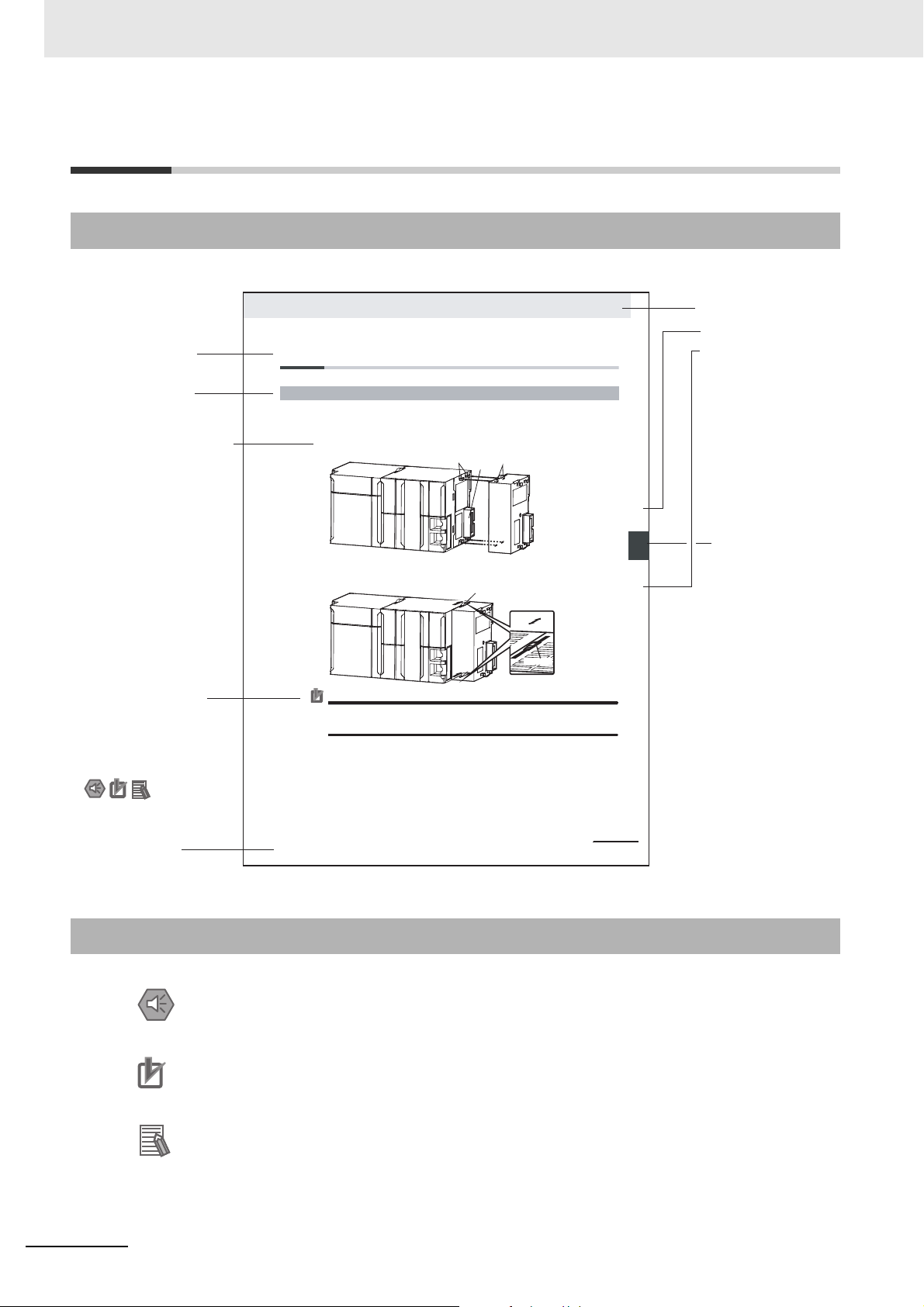
Level 1 heading
Level 2 heading
Level 3 heading
Level 2 heading
A step in a procedure
Manual name
Special information
Level 3 heading
Page tab
Gives the current
headings.
Indicates a procedure.
Icons indicate
precautions, additional
information, or reference
information.
Gives the number
of the main section.
This illustration is provided only as a sample. It may not literally appear in this manual.
The sliders on the tops and bottoms of the Power Supply Unit, CPU Unit, I/O Units, Special I/O
Units, and CPU Bus Units must be completely locked (until they click into place) after connecting
the adjacent Unit connectors.
Manual Structure
Page Structure
The following page structure is used in this manual.
Special Information
Special information in this manual is classified as follows:
Precautions for Safe Use
Precautions on what to do and what not to do to ensure safe usage of the product.
Precautions for Correct Use
Precautions on what to do and what not to do to ensure proper operation and performance.
Additional Information
Additional information to read as required.
This information is provided to increase understanding or make operation easier.
4
Note References are provided to more detailed or related information.
NJ/NX-series CPU Unit Built-in EtherCAT Port User’s Manual (W505)
Page 7

Precaution on Terminology
In this manual, “download” refers to transferring data from the Sysmac Studio to the physical Controller
and “upload” refers to transferring data from the physical Controller to the Sysmac Studio.
For the Sysmac Studio, synchronization is used to both upload and download data. Here, “synchronize”
means to automatically compare the data for the Sysmac Studio on the computer with the data in the
physical Controller and transfer the data in the direction that is specified by the user.
Manual Structure
NJ/NX-series CPU Unit Built-in EtherCAT Port User’s Manual (W505)
5
Page 8

Manual Structure
6
NJ/NX-series CPU Unit Built-in EtherCAT Port User’s Manual (W505)
Page 9

Sections in this Manual
1A
2I
3
4
5
6
7
8
9
1A
2I
3
4
5
6
7
8
9
Introduction Appendices
Part Names and
Slave Settings
Index
EtherCAT Communications
EtherCAT Network Wiring
Setting Up EtherCAT Communications
with the Sysmac Studio
Process Data Communications
and SDO Communications
System-defined Variables That Are Related
to the Built-in EtherCAT Port
Example of Operations for EtherCAT Communications
Troubleshooting
Sections in this Manual
NJ/NX-series CPU Unit Built-in EtherCAT Port User’s Manual (W505)
7
Page 10

CONTENTS
CONTENTS
Introduction ...............................................................................................................1
Intended Audience ........................................................................................................................................ 1
Applicable Products ...................................................................................................................................... 1
Relevant Manuals......................................................................................................2
Manual Structure.......................................................................................................4
Page Structure .............................................................................................................................................. 4
Special Information ....................................................................................................................................... 4
Precaution on Terminology ........................................................................................................................... 5
Sections in this Manual ............................................................................................7
Terms and Conditions Agreement .........................................................................12
Warranty, Limitations of Liability ................................................................................................................. 12
Application Considerations ......................................................................................................................... 13
Disclaimers ................................................................................................................................................. 13
Safety Precautions.................................................................................................. 14
Precautions for Safe Use........................................................................................15
Precautions for Correct Use...................................................................................16
Regulations and Standards....................................................................................17
Conformance to EU Directives .................................................................................................................... 17
Conformance to KC Standards ................................................................................................................... 18
Conformance to Shipbuilding Standards .................................................................................................... 18
Software Licenses and Copyrights ............................................................................................................. 18
Versions ...................................................................................................................19
Checking Versions ...................................................................................................................................... 19
Unit Versions of CPU Units and Sysmac Studio Versions ..........................................................................21
Related Manuals......................................................................................................22
Revision History......................................................................................................24
Section 1 Introduction
1-1 Introduction to EtherCAT ........................................................................................................ 1-2
1-1-1 EtherCAT Features ..................................................................................................................... 1-2
1-1-2 EtherCAT Communications......................................................................................................... 1-2
1-1-3 EtherCAT Features for NJ/NX-series CPU Units ........................................................................1-3
1-2 System Configuration and Configuration Devices............................................................... 1-4
1-2-1 System Configuration..................................................................................................................1-4
1-2-2 Determining the Network Configuration ......................................................................................1-8
1-3 Specifications of Built-in EtherCAT Port ............................................................................... 1-9
1-3-1 Performance Specifications ........................................................................................................ 1-9
1-4 Introduction of Communications ......................................................................................... 1-11
1-4-1 Process Data Communications and SDO Communications ..................................................... 1-11
1-4-2 Other Functions......................................................................................................................... 1-11
1-5 EtherCAT Communications Procedure ............................................................................... 1-13
1-5-1 Overview ...................................................................................................................................1-13
8
NJ/NX-series CPU Unit Built-in EtherCAT Port User’s Manual (W505)
Page 11

CONTENTS
1-5-2 Details....................................................................................................................................... 1-14
Section 2 Part Names and Slave Settings
2-1 Part Names and Functions .....................................................................................................2-2
2-1-1 Built-in EtherCAT Port Indicators ................................................................................................ 2-2
2-1-2 Windows Used in Sysmac Studio ............................................................................................... 2-4
2-1-3 Connecting the Sysmac Studio................................................................................................... 2-7
2-2 Setting the Node Addresses of the EtherCAT Slaves .......................................................... 2-9
2-3 Features of Sysmac Devices ................................................................................................ 2-12
2-3-1 Sysmac Devices ....................................................................................................................... 2-12
2-3-2 Sysmac Device Features.......................................................................................................... 2-12
2-3-3 List of Sysmac Devices............................................................................................................. 2-15
2-3-4 Sysmac Device Features and EtherCAT Masters .................................................................... 2-16
Section 3 EtherCAT Communications
3-1 EtherCAT Communications Types and Settings .................................................................. 3-2
3-1-1 CoE (CAN Application Protocol over EtherCAT) ........................................................................ 3-2
3-1-2 Types of Communications .......................................................................................................... 3-5
3-1-3 Types of EtherCAT Variables...................................................................................................... 3-6
3-1-4 Settings Required for EtherCAT Communications...................................................................... 3-7
3-2 Programming EtherCAT Communications............................................................................ 3-8
3-3 State Transitions for EtherCAT Communications ................................................................ 3-9
3-3-1 Self Diagnosis at Startup ............................................................................................................ 3-9
3-3-2 Control States for EtherCAT Communications............................................................................ 3-9
3-3-3 CPU Unit Status in Relation to EtherCAT ..................................................................................3-11
Section 4 EtherCAT Network Wiring
4-1 Laying the EtherCAT Network ................................................................................................ 4-2
4-1-1 Supported Network Topologies................................................................................................... 4-2
4-1-2 Installation Precautions............................................................................................................... 4-4
4-1-3 Installing EtherCAT Communications Cables ............................................................................. 4-4
4-1-4 Connecting Communications Cables.......................................................................................... 4-8
4-1-5 Cable Connection Procedure...................................................................................................... 4-9
Section 5 Setting Up EtherCAT Communications with
the Sysmac Studio
5-1 Overview of Network Configuration Information.................................................................. 5-2
5-2 Creating the EtherCAT Network Configuration..................................................................... 5-3
5-3 Setting EtherCAT Slave Variables and Axes ......................................................................... 5-6
5-3-1 Registering Device Variables for All EtherCAT Slaves ............................................................... 5-6
5-3-2 Axis Settings for Servo Drives and Encoder Input Slaves ........................................................ 5-10
5-4 EtherCAT Master and Slave Parameter Settings ................................................................ 5-11
5-4-1 Setting EtherCAT Master ...........................................................................................................5-11
5-4-2 Setting EtherCAT Slaves .......................................................................................................... 5-16
5-5 Comparing and Merging EtherCAT Network Configurations ............................................ 5-24
5-5-1 Comparing and Merging with the Actual Network Configuration from the Sysmac Studio ....... 5-24
5-5-2 Automatically Creating the Network Configuration ................................................................... 5-28
5-5-3 Using the Sysmac Studio to Obtain Serial Numbers from the Actual
Network Configuration5-31
NJ/NX-series CPU Unit Built-in EtherCAT Port User’s Manual (W505)
9
Page 12

CONTENTS
5-6 Downloading the Network Configuration Information ....................................................... 5-33
5-6-1 Downloading the Network Configuration Information from the Sysmac Studio......................... 5-33
5-7 Confirming Communications after Completing
EtherCAT Configuration and Settings5-35
Section 6 Process Data Communications and SDO
Communications
6-1 Process Data Communications (PDO Communications) .................................................... 6-2
6-1-1 Allocated Variables for Process Data Communications.............................................................. 6-2
6-1-2 Process Data Communications Refresh Timing..........................................................................6-4
6-1-3 Checking the Validity of the Process Data ..................................................................................6-7
6-1-4 System Response Time in Process Data Communications...................................................... 6-12
6-1-5 I/O Operations for Major Fault Level Controller Errors and I/O Refreshing with
Specified Values6-17
6-2 SDO Communications...........................................................................................................6-21
6-2-1 EtherCAT Instructions ...............................................................................................................6-21
6-2-2 Sample Programming ............................................................................................................... 6-22
6-2-3 Execution Timing of SDO Communications ..............................................................................6-23
6-2-4 Minimum Message Response Time for SDO Communications................................................6-24
6-3 Instructions Used in EtherCAT Communications............................................................... 6-28
6-3-1 EtherCAT Instructions ...............................................................................................................6-28
Section 7 System-defined Variables That Are Related to
the Built-in EtherCAT Port
7-1 System-defined Variables That Are Related to the Built-in EtherCAT Port........................ 7-2
7-1-1 What Are System-defined Variables? .........................................................................................7-2
7-1-2 System-defined Variables ........................................................................................................... 7-3
7-1-3 EtherCAT Master Function Module, Category Name: _EC.........................................................7-9
Section 8 Example of Operations for EtherCAT Communications
8-1 Example of Operations for EtherCAT Communications ...................................................... 8-2
8-1-1 System Configuration Example...................................................................................................8-2
8-1-2 Wiring and Settings.....................................................................................................................8-2
8-1-3 Setting the EtherCAT Network Configuration..............................................................................8-3
8-1-4 Programming...............................................................................................................................8-5
8-1-5 Offline Debugging .......................................................................................................................8-5
8-1-6 Turning the Power ON ................................................................................................................ 8-5
8-1-7 Online Debugging .......................................................................................................................8-5
8-1-8 Downloading the Network Configuration Information and the User Program .............................8-5
8-1-9 Confirming the Start of Communications.....................................................................................8-6
Section 9 Troubleshooting
10
9-1 Overview of Errors .................................................................................................................. 9-2
9-1-1 How to Check for Errors..............................................................................................................9-3
9-1-2 Errors Related to the EtherCAT Master Function Module........................................................... 9-7
9-2 Troubleshooting .................................................................................................................... 9-10
9-2-1 Error Table................................................................................................................................. 9-10
9-2-2 Error Descriptions ..................................................................................................................... 9-16
9-2-3 Resetting Errors ........................................................................................................................ 9-48
9-2-4 Diagnostic and Statistical Information ....................................................................................... 9-50
NJ/NX-series CPU Unit Built-in EtherCAT Port User’s Manual (W505)
Page 13

CONTENTS
9-3 Precautions When Connecting or Disconnecting Slaves during Communications ....... 9-67
9-3-1 Procedure for Connecting and Disconnecting Slaves during Communications........................ 9-67
9-3-2 Prohibition to Physically Disconnecting a Slave and Resetting an Error or
9-4 Replacing Slaves during Communications......................................................................... 9-68
9-4-1 Introduction............................................................................................................................... 9-68
9-4-2 Slave Replacement Methods.................................................................................................... 9-69
9-4-3 Backing Up Settings ................................................................................................................. 9-70
9-4-4 Restoring Settings .................................................................................................................... 9-71
9-4-5 Replacement Procedure........................................................................................................... 9-73
Appendices
A-1 EtherCAT Status in Relation to CPU Unit Status ..................................................................A-2
A-1-1 When the Power Supply Is Turned ON.......................................................................................A-2
A-1-2 CPU Unit Operating Modes........................................................................................................ A-3
A-1-3 Controller Errors Other Than Errors in the Built-in EtherCAT Master .........................................A-5
A-1-4 Others.........................................................................................................................................A-6
A-1-5 When the Power Supply Is Turned OFF.....................................................................................A-7
A-2 Monitoring Packets..................................................................................................................A-8
A-3 Multi-vendor Environments ..................................................................................................A-17
A-3-1 EtherCAT Slave Information File (ESI Files).............................................................................A-17
A-3-2 Connecting Slaves from Other Manufacturers to an OMRON Master......................................A-19
A-3-3 Installing ESI Files .................................................................................................................... A-19
A-3-4 Editing PDO Entry Tables ......................................................................................................... A-25
A-3-5 Settings for MDP-compatible Slaves from Other Manufacturers.............................................. A-28
A-4 Glossary .................................................................................................................................A-31
A-5 Version Information...............................................................................................................A-33
Connecting a Slave at the Same Time9-67
Index
NJ/NX-series CPU Unit Built-in EtherCAT Port User’s Manual (W505)
11
Page 14

Terms and Conditions Agreement
Terms and Conditions Agreement
Warranty, Limitations of Liability
Warranties
Exclusive Warranty
Omron’s exclusive warranty is that the Products will be free from defects in materials and workmanship for a period of twelve months from the date of sale by Omron (or such other period expressed in
writing by Omron). Omron disclaims all other warranties, express or implied.
Limitations
OMRON MAKES NO WARRANTY OR REPRESENTATION, EXPRESS OR IMPLIED, ABOUT
NON-INFRINGEMENT, MERCHANTABILITY OR FITNESS FOR A PARTICULAR PURPOSE OF
THE PRODUCTS. BUYER ACKNOWLEDGES THAT IT ALONE HAS DETERMINED THAT THE
PRODUCTS WILL SUITABLY MEET THE REQUIREMENTS OF THEIR INTENDED USE.
Omron further disclaims all warranties and responsibility of any type for claims or expenses based
on infringement by the Products or otherwise of any intellectual property right.
Buyer Remedy
Omron’s sole obligation hereunder shall be, at Omron’s election, to (i) replace (in the form originally
shipped with Buyer responsible for labor charges for removal or replacement thereof) the non-complying Product, (ii) repair the non-complying Product, or (iii) repay or credit Buyer an amount equal
to the purchase price of the non-complying Product; provided that in no event shall Omron be
responsible for warranty, repair, indemnity or any other claims or expenses regarding the Products
unless Omron’s analysis confirms that the Products were properly handled, stored, installed and
maintained and not subject to contamination, abuse, misuse or inappropriate modification. Return of
any Products by Buyer must be approved in writing by Omron before shipment. Omron Companies
shall not be liable for the suitability or unsuitability or the results from the use of Products in combination with any electrical or electronic components, circuits, system assemblies or any other materials or substances or environments. Any advice, recommendations or information given orally or in
writing, are not to be construed as an amendment or addition to the above warranty.
See http://www.omron.com/global/ or contact your Omron representative for published information.
Limitation on Liability; Etc
OMRON COMPANIES SHALL NOT BE LIABLE FOR SPECIAL, INDIRECT, INCIDENTAL, OR CONSEQUENTIAL DAMAGES, LOSS OF PROFITS OR PRODUCTION OR COMMERCIAL LOSS IN ANY
WAY CONNECTED WITH THE PRODUCTS, WHETHER SUCH CLAIM IS BASED IN CONTRACT,
WARRANTY, NEGLIGENCE OR STRICT LIABILITY.
Further, in no event shall liability of Omron Companies exceed the individual price of the Product on
which liability is asserted.
12
NJ/NX-series CPU Unit Built-in EtherCAT Port User’s Manual (W505)
Page 15

Application Considerations
Suitability of Use
Omron Companies shall not be responsible for conformity with any standards, codes or regulations
which apply to the combination of the Product in the Buyer’s application or use of the Product. At
Buyer’s request, Omron will provide applicable third party certification documents identifying ratings
and limitations of use which apply to the Product. This information by itself is not sufficient for a complete determination of the suitability of the Product in combination with the end product, machine, system, or other application or use. Buyer shall be solely responsible for determining appropriateness of
the particular Product with respect to Buyer’s application, product or system. Buyer shall take application responsibility in all cases.
NEVER USE THE PRODUCT FOR AN APPLICATION INVOLVING SERIOUS RISK TO LIFE OR
PROPERTY WITHOUT ENSURING THAT THE SYSTEM AS A WHOLE HAS BEEN DESIGNED TO
ADDRESS THE RISKS, AND THAT THE OMRON PRODUCT(S) IS PROPERLY RATED AND
INSTALLED FOR THE INTENDED USE WITHIN THE OVERALL EQUIPMENT OR SYSTEM.
Terms and Conditions Agreement
Programmable Products
Omron Companies shall not be responsible for the user’s programming of a programmable Product, or
any consequence thereof.
Disclaimers
Performance Data
Data presented in Omron Company websites, catalogs and other materials is provided as a guide for
the user in determining suitability and does not constitute a warranty. It may represent the result of
Omron’s test conditions, and the user must correlate it to actual application requirements. Actual performance is subject to the Omron’s Warranty and Limitations of Liability.
Change in Specifications
Product specifications and accessories may be changed at any time based on improvements and other
reasons. It is our practice to change part numbers when published ratings or features are changed, or
when significant construction changes are made. However, some specifications of the Product may be
changed without any notice. When in doubt, special part numbers may be assigned to fix or establish
key specifications for your application. Please consult with your Omron’s representative at any time to
confirm actual specifications of purchased Product.
Errors and Omissions
Information presented by Omron Companies has been checked and is believed to be accurate; however, no responsibility is assumed for clerical, typographical or proofreading errors or omissions.
NJ/NX-series CPU Unit Built-in EtherCAT Port User’s Manual (W505)
13
Page 16

Safety Precautions
Safety Precautions
Refer to the following manuals for safety precautions.
• NX-series CPU Unit Hardware User’s Manual (Cat No. W535)
• NX-series NX1P2 CPU Unit Hardware User’s Manual (Cat. No. W578)
• NJ-series CPU Unit Hardware User’s Manual (Cat No. W500)
14
NJ/NX-series CPU Unit Built-in EtherCAT Port User’s Manual (W505)
Page 17

Precautions for Safe Use
Refer to the following manuals for precautions for safe use.
• NX-series CPU Unit Hardware User’s Manual (Cat No. W535)
• NX-series NX1P2 CPU Unit Hardware User’s Manual (Cat. No. W578)
• NJ-series CPU Unit Hardware User’s Manual (Cat No. W500)
Precautions for Safe Use
NJ/NX-series CPU Unit Built-in EtherCAT Port User’s Manual (W505)
15
Page 18

Precautions for Correct Use
Precautions for Correct Use
Refer to the following manuals for precautions for correct use.
• NX-series CPU Unit Hardware User’s Manual (Cat No. W535)
• NX-series NX1P2 CPU Unit Hardware User’s Manual (Cat. No. W578)
• NJ-series CPU Unit Hardware User’s Manual (Cat No. W500)
16
NJ/NX-series CPU Unit Built-in EtherCAT Port User’s Manual (W505)
Page 19

Regulations and Standards
Conformance to EU Directives
Applicable Directives
• EMC Directives
• Low Voltage Directive
Concepts
EMC Directive
OMRON devices that comply with EU Directives also conform to the related EMC standards so that
they can be more easily built into other devices or the overall machine. The actual products have
been checked for conformity to EMC standards.*
Whether the products conform to the standards in the system used by the customer, however, must
be checked by the customer. EMC-related performance of the OMRON devices that comply with EU
Directives will vary depending on the configuration, wiring, and other conditions of the equipment or
control panel on which the OMRON devices are installed. The customer must, therefore, perform
the final check to confirm that devices and the overall machine conform to EMC standards.
* Applicable EMC (Electromagnetic Compatibility) standards are as follows:
EMS (Electromagnetic Susceptibility): EN 61131-2
EMI (Electromagnetic Interference): EN 61131-2 (Radiated emission: 10-m regulations)
Regulations and Standards
Low Voltage Directive
Always ensure that devices operating at voltages of 50 to 1,000 VAC and 75 to 1,500 VDC meet the
required safety standards. The applicable directive is EN 61010-2-201.
Conformance to EU Directives
The NJ/NX-series Controllers comply with EU Directives. To ensure that the machine or device in
which the NJ/NX-series Controller is used complies with EU Directives, the Controller must be
installed as follows:
• The NJ/NX-series Controller must be installed within a control panel.
• You must use the power supply in SELV specifications for the DC power supplies connected to
DC Power Supply Units and I/O Units.
• NJ/NX-series Controllers that comply with EU Directives also conform to the Common Emission
Standard (EN 61000-6-4). Radiated emission characteristics (10-m regulations) may vary
depending on the configuration of the control panel used, other devices connected to the control
panel, wiring, and other conditions.
You must therefore confirm that the overall machine or equipment complies with EU Directives.
NJ/NX-series CPU Unit Built-in EtherCAT Port User’s Manual (W505)
17
Page 20

Regulations and Standards
Conformance to KC Standards
Observe the following precaution if you use NX-series Units in Korea.
Class A Device (Broadcasting Communications Device for Office Use)
This device obtained EMC registration for office use (Class A), and it is intended to be used in places
other than homes.
Sellers and/or users need to take note of this.
Conformance to Shipbuilding Standards
The NJ/NX-series Controllers comply with the following shipbuilding standards. Applicability to the
shipbuilding standards is based on certain usage conditions. It may not be possible to use the product in some locations. Contact your OMRON representative before attempting to use a Controller on
a ship.
Usage Conditions for NK and LR Shipbuilding Standards
• The NJ/NX-series Controller must be installed within a control panel.
• Gaps in the door to the control panel must be completely filled or covered with gaskets or other
material.
• The following noise filter must be connected to the power supply line.
Noise Filter
Manufacturer Model
Cosel Co., Ltd. TAH-06-683
Software Licenses and Copyrights
This product incorporates certain third party software. The license and copyright information associated with this software is available at http://www.fa.omron.co.jp/nj_info_e/.
18
NJ/NX-series CPU Unit Built-in EtherCAT Port User’s Manual (W505)
Page 21
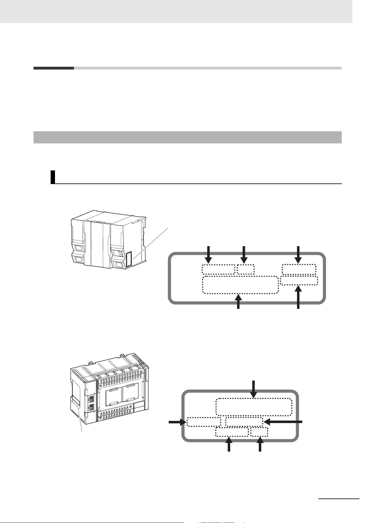
Versions
ID information indication
Lot number Serial number Unit version
MAC address Hardware revision
LOT No. DDMYY xxxx Ver.1.
PORT1 : HW Rev.
PORT2 :
ID information indication
Lot number Serial number
Unit version
PORT1 :
PORT2 :
Ver.1. HW Rev.
LOT No. DDMYY xxxx
MAC address
Hardware
revision
Hardware revisions and unit versions are used to manage the hardware and software in NJ/NX-series
Units and EtherCAT slaves. The hardware revision or unit version is updated each time there is a
change in hardware or software specifications. Even when two Units or EtherCAT slaves have the
same model number, they will have functional or performance differences if they have different hardware revisions or unit versions.
Checking Versions
You can check versions on the ID information indications or with the Sysmac Studio.
Checking Unit Versions on ID Information Indications
The unit version is given on the ID information indication on the side of the product.
Versions
The ID information on an NX-series NX701- CPU Unit is shown below.
Note The hardware revision is not displayed for the Unit that the hardware revision is in blank.
The ID information on an NX-series NX1P2- CPU Unit is shown below.
Note The hardware revision is not displayed for the Unit that the hardware revision is in blank.
NJ/NX-series CPU Unit Built-in EtherCAT Port User’s Manual (W505)
19
Page 22
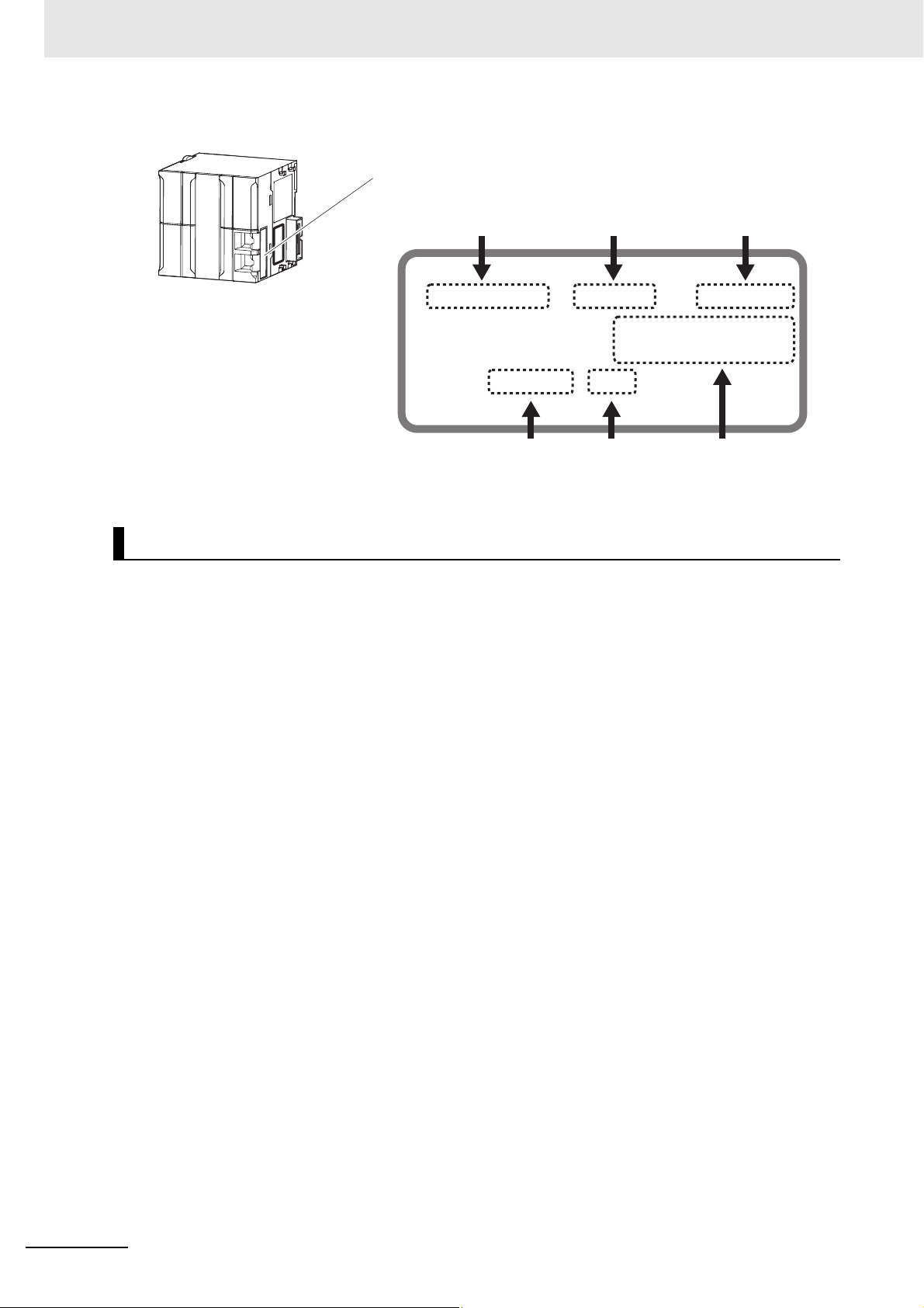
Versions
The ID information on an NJ-series NJ501- CPU Unit is shown below.
ID information indication
Unit model
NJ501
PORT1 MAC ADDRESS:
PORT2 MAC ADDRESS:
Lot No. DDMYY
Note The hardware revision is not displayed for the Unit that the hardware revision is in blank.
-
Lot number Serial number MAC address
Unit version Hardware revision
Ver.1.
xxxx
HW Rev.
Checking Unit Versions with the Sysmac Studio
You can use the Sysmac Studio to check unit versions. The procedure is different for Units and for EtherCAT slaves.
Checking the Unit Version of an NX-series CPU Unit
You can use the Production Information while the Sysmac Studio is online to check the unit version
of a Unit. You can do this for the CPU Unit. For an NX1P2 CPU Unit, you can also check the unit
versions of the NX Units on the CPU Rack and Option Boards.
1
Right-click CPU Rack under Configurations and Setup - CPU/Expansion Racks in the Multiview Explorer and select Production Information.
The Production Information Dialog Box is displayed.
Checking the Unit Version of an NJ-series CPU Unit
You can use the Production Information while the Sysmac Studio is online to check the unit version
of a Unit. You can do this for the CPU Unit, CJ-series Special I/O Units, and CJ-series CPU Bus
Units. You cannot check the unit versions of CJ-series Basic I/O Units with the Sysmac Studio.
Use the following procedure to check the unit version.
1
Double-click CPU/Expansion Racks under Configurations and Setup in the Multiview
Explorer. Or, right-click CPU/Expansion Racks under Configurations and Setup and select
Edit from the menu.
The Unit Editor is displayed.
2
Right-click any open space in the Unit Editor and select Production Information.
The Production Information Dialog Box is displayed.
Changing Information Displayed in Production Information Dialog Box
1
Click the Show Detail or Show Outline Button at the lower right of the Production Information
Dialog Box.
The view will change between the production information details and outline.
20
NJ/NX-series CPU Unit Built-in EtherCAT Port User’s Manual (W505)
Page 23
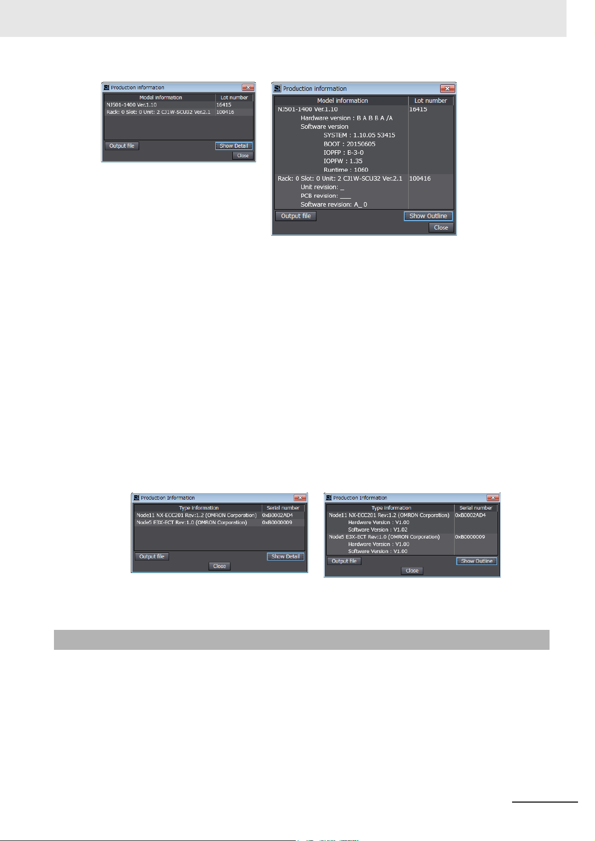
Versions
Outline View Detail View
The information that is displayed is different for the Outline View and Detail View. The Detail View
displays the unit version, hardware version, and software versions. The Outline View displays only
the unit version.
Note The hardware revision is separated by “/” and displayed on the right of the hardware version. The hardware
revision is not displayed for the Unit that the hardware revision is in blank.
Checking the Unit Version of an EtherCAT Slave
You can use the Production Information while the Sysmac Studio is online to check the unit version
of an EtherCAT slave. Use the following procedure to check the unit version.
1
Double-click EtherCAT under Configurations and Setup in the Multiview Explorer. Or, rightclick EtherCAT under Configurations and Setup and select Edit from the menu.
The EtherCAT Tab Page is displayed.
2
Right-click the master on the EtherCAT Tab Page and select Display Production Information.
The Production Information Dialog Box is displayed.
The unit version is displayed after “Rev.”
Outline View Detail View
Unit Versions of CPU Units and Sysmac Studio Versions
The functions that are supported depend on the unit version of the NJ/NX-series CPU Unit. The version
of Sysmac Studio that supports the functions that were added for an upgrade is also required to use
those functions.
Refer to the NJ/NX-series CPU Unit Software User’s Manual (Cat. No. W501-E1-02 or later) for the
relationship between the unit versions of the CPU Units and the Sysmac Studio versions, and for the
functions that are supported by each unit version.
NJ/NX-series CPU Unit Built-in EtherCAT Port User’s Manual (W505)
21
Page 24

Related Manuals
Related Manuals
The followings are the manuals related to this manual. Use these manuals for reference.
Manual name Cat. No. Model numbers Application Description
NX-series CPU Unit
Hardware User’s Manual
NX-series NX1P2 CPU
Unit Hardware User's
Manual
NJ-series CPU Unit
Hardware User’s Manual
NJ/NX-series CPU Unit
Software User’s Manual
NX-series NX1P2 CPU
Unit Built-in I/O and
Option Board User's
Manual
NJ/NX-series Instructions
Reference Manual
NJ/NX-series CPU Unit
Motion Control User’s
Manual
W535 NX701- Learning the basic specifi-
cations of the NX701 CPU
Units, including introductory information, designing,
installation, and maintenance.
Mainly hardware information is provided.
W578 NX1P2- Learning the basic specifi-
cations of the NX1P2 CPU
Units, including introductory information, designing,
installation, and maintenance.
Mainly hardware information is provided.
W500 NJ501-
NJ301-
NJ101-
W501 NX701-
NX1P2-
NJ501-
NJ301-
NJ101-
W579 NX1P2- Learning about the details
W502 NX701-
NX1P2-
NJ501-
NJ301-
NJ101-
W507 NX701-
NX1P2-
NJ501-
NJ301-
NJ101-
Learning the basic specifications of the NJ-series
CPU Units, including introductory information,
designing, installation, and
maintenance.
Mainly hardware information is provided.
Learning how to program
and set up an NJ/NXseries CPU Unit.
Mainly software information is provided.
of functions only for an NXseries NX1P2 CPU Unit
and an introduction of functions for an NJ/NX-series
CPU Unit.
Learning detailed specifications on the basic
instructions of an NJ/NXseries CPU Unit.
Learning about motion
control settings and programming concepts.
An introduction to the entire NX701 system is
provided along with the following information on
the CPU Unit.
• Features and system configuration
• Introduction
• Part names and functions
• General specifications
• Installation and wiring
• Maintenance and inspection
An introduction to the entire NX1P2 system is
provided along with the following information on
the CPU Unit.
• Features and system configuration
• Introduction
• Part names and functions
• General specifications
• Installation and wiring
• Maintenance and inspection
An introduction to the entire NJ-series system is
provided along with the following information on
the CPU Unit.
• Features and system configuration
• Introduction
• Part names and functions
• General specifications
• Installation and wiring
• Maintenance and inspection
The following information is provided on a Controller built with an NJ/NX-series CPU Unit.
• CPU Unit operation
• CPU Unit features
• Initial settings
gramming based on IEC 61131-3 lan-
• Pro
e specifications
guag
Of the functions for an NX1P2 CPU Unit, the following information is provided.
• Built-in I/O
• Serial Communications Option Boards
• Analog I/O Option Boards
An introduction of following functions for an
NJ/NX-series CPU Unit is also provided.
• Motion control functions
• EtherNet/IP communications functions
• EtherCAT communications functions
The instructions in the instruction set (IEC
61131-3 specifications) are described.
The settings and operation of the CPU Unit and
programming concepts for motion control are
described.
22
NJ/NX-series CPU Unit Built-in EtherCAT Port User’s Manual (W505)
Page 25

Manual name Cat. No. Model numbers Application Description
NJ/NX-series
Motion Control Instructions Reference Manual
NJ/NX-series
CPU Unit
Built-in EtherCAT Port
User’s Manual
NJ/NX-series
CPU Unit
Built-in EtherNet/IP
User’s Manual
NJ-series
SECS/GEM CPU Units
User’s Manual
NJ-series NJ Robotics
CPU Unit User’s Manual
NJ/NX-series
Troubleshooting Manual
Sysmac Studio Version 1
Operation Manual
NX-series
EtherCAT Coupler Unit
User’s Manual
W508 NX701-
NX1P2-
NJ501-
NJ301-
NJ101-
W505 NX701-
NX1P2-
NJ501-
NJ301-
NJ101-
W506 NX701-
Port
W528 NJ501-1340 Using the GEM Services
W539 NJ501-4 Controlling robots with NJ-
W503 NX701-
W504 SYSMAC
W519 NX-ECC Learning how to use an
NX1P2-
NJ501-
NJ301-
NJ101-
NX1P2-
NJ501-
NJ301-
NJ101-
-SE2
Learning about the specifications of the motion control instructions.
Using the built-in EtherCAT
port on an NJ/NX-series
CPU Unit.
Using the built-in EtherNet/IP port on an NJ/NXseries CPU Unit.
with NJ-series Controllers.
series CPU Units.
Learning about the errors
that may be detected in an
NJ/NX-series Controller.
Learning about the operating procedures and functions of the Sysmac Studio.
NX-series EtherCAT Coupler Unit and EtherCAT
Slave Terminals.
The motion control instructions are described.
Information on the built-in EtherCAT port is provided.
This manual provides an introduction and provides information on the configuration, features,
and setup.
Information on the built-in EtherNet/IP port is
provided.
Information is provided on the basic setup, tag
data links, and other features.
Provides information on the GEM Services.
Describes the functionality to control robots.
Concepts on managing errors that may be
detected in an NJ/NX-series Controller and
information on individual errors are described.
Describes the operating procedures of the Sysmac Studio.
The following items are described: the overall
system and configuration methods of an EtherCAT Slave Terminal (which consists of an NXseries EtherCAT Coupler Unit and NX Units),
and information on hardware, setup, and functions to set up, control, and monitor NX Units
through EtherCAT.
Related Manuals
NJ/NX-series CPU Unit Built-in EtherCAT Port User’s Manual (W505)
23
Page 26

Revision History
W505-E1-15
Revision code
Cat. No.
Revision History
A manual revision code appears as a suffix to the catalog number on the front and back covers of the
manual.
Revision code Date Revised content
01 July 2011 Original production
02 March 2012 Added information on the NJ301-
03 May 2012 • Added information on functional support for unit version
04 August 2012 • Added information on functional support for unit version
05 February 2013 • Added information on functional support for unit version
06 April 2013 • Added information on functional support for unit version
07 June 2013 • Added information on functional support for unit version
08 September 2013 • Added information on functional support for unit version
09 December 2013 • Added information on functional support for unit version
10 July 2014 • Corrected mistakes.
11 January 2015 • Added information on functional support for unit version
12 April 2015 • Added information on the NX701-
13 April 2016 • Added information on functional support for unit version 1.11
14 October 2016 • Added information on the NX1P2-
15 April 2017 • Corrected mistakes.
and corrected mis-
takes.
1.02 of the CPU Units.
• Corrected mistakes.
1.03 of the CPU Units.
• Corrected mistakes.
1.04 of the CPU Units.
• Corrected mistakes.
1.05 of the CPU Units.
• Corrected mistakes.
1.06 of the CPU Units.
• Corrected mistakes.
1.07 of the CPU Units.
• Corrected mistakes.
1.08 of the CPU Units.
• Corrected mistakes.
1.10 of the CPU Units.
• Corrected mistakes.
• Added information on the NJ101-
• Corrected mistakes.
of the CPU Units.
• Corrected mistakes.
• Corrected mistakes.
.
.
.
24
NJ/NX-series CPU Unit Built-in EtherCAT Port User’s Manual (W505)
Page 27

Introduction
This section provides an overview of EtherCAT communications, describes the system
configuration and specifications, and provides operating procedures.
1-1 Introduction to EtherCAT . . . . . . . . . . . . . . . . . . . . . . . . . . . . . . . . . . . . . . . 1-2
1-1-1 EtherCAT Features . . . . . . . . . . . . . . . . . . . . . . . . . . . . . . . . . . . . . . . . . . . . . 1-2
1-1-2 EtherCAT Communications . . . . . . . . . . . . . . . . . . . . . . . . . . . . . . . . . . . . . . . 1-2
1-1-3 EtherCAT Features for NJ/NX-series CPU Units . . . . . . . . . . . . . . . . . . . . . . . 1-3
1-2 System Configuration and Configuration Devices . . . . . . . . . . . . . . . . . . . 1-4
1-2-1 System Configuration . . . . . . . . . . . . . . . . . . . . . . . . . . . . . . . . . . . . . . . . . . . 1-4
1-2-2 Determining the Network Configuration . . . . . . . . . . . . . . . . . . . . . . . . . . . . . . 1-8
1-3 Specifications of Built-in EtherCAT Port . . . . . . . . . . . . . . . . . . . . . . . . . . . 1-9
1-3-1 Performance Specifications . . . . . . . . . . . . . . . . . . . . . . . . . . . . . . . . . . . . . . . 1-9
1-4 Introduction of Communications . . . . . . . . . . . . . . . . . . . . . . . . . . . . . . . . 1-11
1-4-1 Process Data Communications and SDO Communications . . . . . . . . . . . . . .1-11
1-4-2 Other Functions . . . . . . . . . . . . . . . . . . . . . . . . . . . . . . . . . . . . . . . . . . . . . . . .1-11
1-5 EtherCAT Communications Procedure . . . . . . . . . . . . . . . . . . . . . . . . . . . 1-13
1-5-1 Overview . . . . . . . . . . . . . . . . . . . . . . . . . . . . . . . . . . . . . . . . . . . . . . . . . . . . 1-13
1-5-2 Details . . . . . . . . . . . . . . . . . . . . . . . . . . . . . . . . . . . . . . . . . . . . . . . . . . . . . . 1-14
1
NJ/NX-series CPU Unit Built-in EtherCAT Port User’s Manual (W505)
1-1
Page 28
1 Introduction
IN
OUT
Slave
• Output data addressed to the local node is read.
• Input data is written.
Ethernet frames
EtherCAT master
Slave
data
Slave
1-1 Introduction to EtherCAT
EtherCAT (Ethernet Control Automation Technology) is a high-performance industrial network system
that enables faster and more efficient communications based on Ethernet. Each node achieves a short
communications cycle time by transmitting Ethernet frames at high speed. Furthermore, even though
EtherCAT is a unique protocol, it offers excellent general-purpose applicability. For example, you can
use Ethernet cables because EtherCAT utilizes standard Ethernet technology for the physical layer.
And the effectiveness of EtherCAT can be fully utilized not only in large control systems that require
high processing speeds and system integrity, but also in small and medium control systems.
1-1-1 EtherCAT Features
EtherCAT provides the following features.
High-speed Communications at 100 Mbps
The I/O response time from signal input to signal output has been significantly reduced. By fully utilizing
the optimized Ethernet frame bandwidth to transmit data using a high-speed repeat method, it is possible to efficiently transmit a wide variety of data.
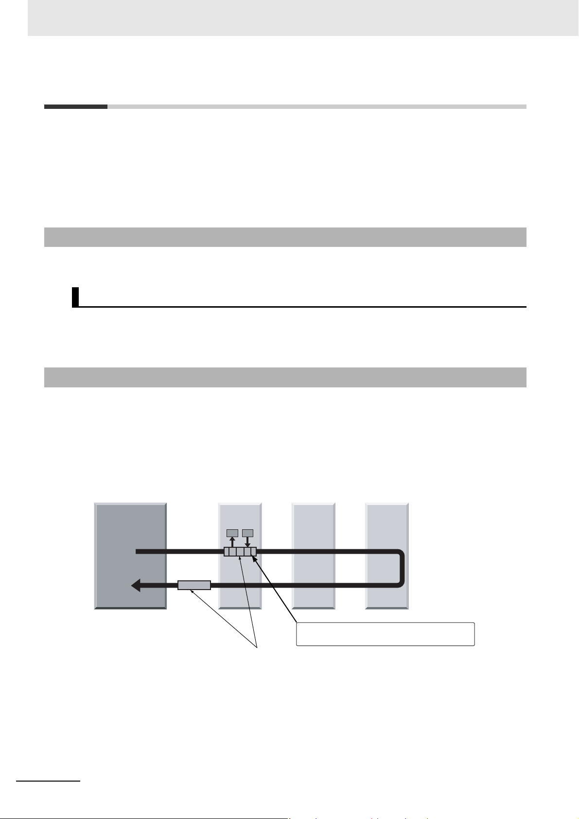
1-1-2 EtherCAT Communications
EtherCAT does not send data to individual slave nodes on the network, instead, it passes Ethernet
frames through all of the slave nodes.
When frame passes through a slave node, the slave node reads and writes data in the areas allocated
to it in the frames in a few nanoseconds.
The Ethernet frames transmitted by the EtherCAT master pass through all EtherCAT slaves without
stopping. The last slave returns all of the frames, which again pass through all of the slaves before
returning to the EtherCAT master.
This mechanism ensures high speed and realtime data transmission.
1-2
NJ/NX-series CPU Unit Built-in EtherCAT Port User’s Manual (W505)
Page 29

1-1-3 EtherCAT Features for NJ/NX-series CPU Units
EtherCAT in the NJ/NX-series CPU Units has the following features.
Synchronization of the CPU Unit Processing Period and the
EtherCAT Communications Cycle
The period of sequence processing and motion processing in the CPU Unit matches the process data
communications cycle of EtherCAT.
This enables high-precision sequence control and motion control with a stable fixed period.
Also, with the NX701 CPU Unit, slaves to be synchronized can be divided into two groups with different
process data communications cycles. This means that slaves are separately processed in one group
that needs high-speed communications and the other that needs not.
Accessing Data with Device Variables without Considering
Addresses
1 Introduction
1-1 Introduction to EtherCAT
1
1-1-3 EtherCAT Features for NJ/NX-series CPU Units
EtherCAT slaves are accessed using device variables that are assigned to the I/O ports of the EtherCAT slaves. Various types of data in Servo Drive and the encoder input slaves are accessed using
structure-type Axis Variables prepared in advance.
This enables access to slaves on EtherCAT without regard to addresses.
Optimum Functionality and Ease of Operation Based on Unified
Specifications
You can use the NJ/NX-series Machine Automation Controllers together with Sysmac devices* and the
Sysmac Studio Automation Software to achieve optimum functionality and ease of operation.
* “Sysmac devices” is a generic name for EtherCAT slaves and other OMRON control components that were
designed with the same communications and user interface specifications.
NJ/NX-series CPU Unit Built-in EtherCAT Port User’s Manual (W505)
1-3
Page 30
1 Introduction
1-2 System Configuration and
Configuration Devices
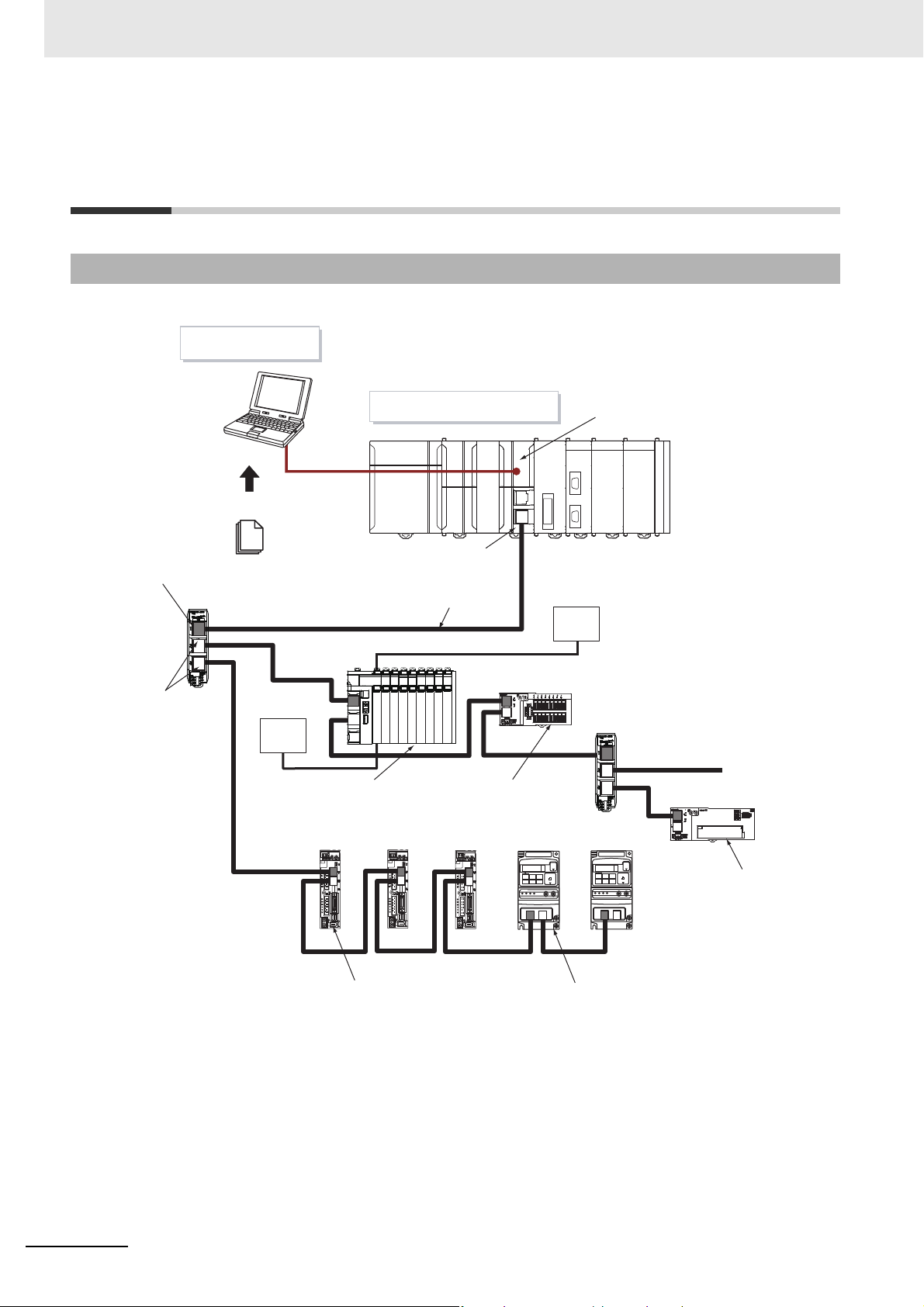
1-2-1 System Configuration
The EtherCAT network configuration and configuration devices are shown below.
Sysmac Studio
Input port
EtherCAT Junction Slave
Output ports
ESI files
.xml
I/O power supply
NJ/NX-series CPU Unit
Built-in EtherCAT port
Communications cable
EtherCAT Slave
Terminal
(EtherCAT slave)
ADR
ADR
EtherCAT master
Unit power supply
EtherCAT Junction Slave
Digital I/O Slave
(EtherCAT Slave)
ADR
1-4
Analog I/O Slave
(EtherCAT slave)
Servo Drive (EtherCAT slave) Inverter (EtherCAT slave)
Outlines of the configuration devices are given below.
EtherCAT Master
The EtherCAT master manages the network, monitors the status of slaves, and exchanges I/O data
with slaves. There is one output port.
Output Port
The output port transmits EtherCAT communications data to other devices. When you connect the
output port to another device, always connect it to the input port on the other device. Normal communications will not be possible if you connect to the output port on another device.
NJ/NX-series CPU Unit Built-in EtherCAT Port User’s Manual (W505)
Page 31

1 Introduction
Input Port
This port is used to input EtherCAT communications data. Always connect it to the output port on
another device. Normal communications will not be possible if you connect to the input port on
another device.
EtherCAT Slaves
Each EtherCAT slave outputs the output data that it received from the EtherCAT master through the
EtherCAT network. It also sends input data to the EtherCAT master through the EtherCAT network.
• Each slave has one input port and at least one output port.
• In the EtherCAT network, you can use the salves and Junction Slaves that are listed below in total
up to the maximum number of slaves.
• Assign node addresses to the slaves and Junction Slaves. The node address can be any value
within the settable node address range, and can be assigned without any distinction between the
slaves and Junction Slaves. But any node address should not be used more than once.
• The EtherCAT slaves can be classified into two: whether they support synchronization based on
a distributed clock (DC) or not.
a) Non-synced Slaves
These slaves perform sequence control that does not require synchronization between them.
Digital I/O Slaves and Analog I/O Slaves are among this type. They do not support a distributed clock (DC).
b) Synced Slaves
These slaves are synchronized based on the distributed clock (DC). Servo Drives and
encoder input slaves are among this type.
1-2 System Configuration and
Configuration Devices
1
1-2-1 System Configuration
Note 1 Refer to 1-3-1 Performance Specifications for details on the maximum number of slaves
and the settable node address range.
2 The slaves are synchronized even when multiple non-synced slaves and Junction Slaves
are connected.
The following tables lists some of the OMRON EtherCAT slaves that are available.
Name Typ e Model
Digital I/O Slaves Slaves with screw
terminals and 2-tier
terminal block
Slaves with screw
terminals and 3-tier
terminal block
Slaves with e-CON
connectors
Analog I/O
Slaves
NX-series EtherCAT Coupler Unit
Multifunctional,
Compact Inverters
Advanced Generalpurpose Inverters
Slaves with screw
terminals and 2-tier
terminal block
NX Series
MX2 Series 3G3MX2 with
RX Series 3G3RX-V1 with
GX-D161/OC1601 Non-synced
GX-ID162/OD162/MD162 Non-synced
GX-D168/D328 Non-synced
GX-AD0471/DA0271 Non-synced
NX-ECC201
NX-ECC202
NX-ECC203
EtherCAT Communications Unit
3G3AX-MX2-ECT
EtherCAT Communications Unit
3G3AX-RX-ECT
Synced/
Non-synced
Slaves
Slaves
Slaves
Slaves
Slaves
*2
*3
*4
Synced
Slaves
Non-synced
Slaves
Non-synced
Slaves
Reference
Clock*
Exist Not
Exist Not
Exist Not
Exist Not
Exist Not possible
Exist Not
Exist Not possible
Assigning
1
possible
possible
possible
possible
(Some of the
connected
NX Units can
be assigned
to an axis.)
possible
an axis
NJ/NX-series CPU Unit Built-in EtherCAT Port User’s Manual (W505)
1-5
Page 32

1 Introduction
Precautions for Safe Use
Name Type Model
AC Servo Drive G5-series Servo
Drive with EtherCAT
communications
Linear Servo Drives G5-series Linear
Servo Drives with
EtherCAT communications
Encoder Input
Slaves
Vision Sensors FH Series FH-1
Specialized Vision
Sensors for Positioning
Digital Sensor Communications Unit
Fiber Sensor Communications Unit
Confocal Fiber Type
Displacement Sensors
Slave with 3-tier terminal block
FQ-M-series Sensors
with EtherCAT Communications
FZM1-series Vision
Sensors
E3NW Series E3NW-ECT Synced
E3X Series E3X-ECT Synced
ZW Series ZW-CE1 Synced
R88M-K/R88D-KN-ECT Synced
R88L-EC/R88D-KN-ECT-L Synced
GX-EC0211/EC0241 Synced
FH-3
FQ-MS12(-)-ECT Synced
FZM1-35-ECT Synced
Synced/
Non-synced
Slaves
Slaves
Slaves
Slaves
Synced
Slaves
Slaves
Slaves
Slaves
Slaves
Slaves
Reference
Clock*
Exist Possible
Exist Possible
Exist Possible
Exist Not possible
Exist Not possible
Exist Not possible
Exist Not possible
Exist Not possible
Exist Not possible
1
Assigning
an axis
*1 Shows whether or not the slave provides a reference clock. A slave or a master that provides a reference clock is
required for a system configuration that enables synchronization between slaves based on a distributed clock (DC). When
you connect a slave that supports the reference clock, you must meet some conditions. Refer to 4-1-1 Supported Network
Topologies for detail on the conditions.
*2 A CPU Unit with unit version 1.05 or later and Sysmac Studio version 1.06 or higher are required.
*3 A CPU Unit with unit version 1.07 or later and Sysmac Studio version 1.08 or higher are required.
*4 A CPU Unit with unit version 1.07 or later and Sysmac Studio version 1.11 or higher are required.
EtherCAT Junction Slave
This is a special Unit for branching EtherCAT network wiring. Cascade connections are possible
within the range of node addresses that the EtherCAT master can handle.
Each Junction Slave has one input port and more than one output port. The output ports on each
Junction Slave can be connected to another Junction Slave or other EtherCAT slaves.
The Junction Slave supports the reference clock that is required for a system configuration that
enables synchronization between slaves based on a distributed clock (DC).
The following models are examples of some of the OMRON EtherCAT slaves.
Slave type/name Number of ports Model
EtherCAT Junction Slave 3 ports GX-JC03
6 ports
GX-JC06
You cannot use standard Ethernet hubs or repeater hubs with EtherCAT communications. If you
use one of these, a major fault level error or other error may occur.
1-6
NJ/NX-series CPU Unit Built-in EtherCAT Port User’s Manual (W505)
Page 33

1 Introduction
Precautions for Correct UsePrecautions for Correct Use
Additional Information
• GX-JC03 and GX-JC06 EtherCAT Junction Slaves do not have hardware switches for node
address setting. The Sysmac Studio is required to set the node addresses for these slaves.
The node addresses are set to 0 by default. If you use these slaves with the default node
address, a Network Configuration Verification Error will occur.
• A GX-JC03 EtherCAT Junction Slave needs only one node address. A GX-JC06 EtherCAT
Junction Slave needs two node addresses.
A GX-JC06 EtherCAT Junction Slave which appears to be one Unit is actually composed of two
slaves. The two slaves appear as “Main device” and “Sub-device” in the Sysmac Studio, respectively, as shown in the figure below. The In port of Sub-device appears as “Internal Port” in the
Sysmac Studio and it is internally connected to the Main device.
1-2 System Configuration and
Configuration Devices
1
1-2-1 System Configuration
Sysmac Studio
The Sysmac Studio runs on a personal computer and it is used to configure EtherCAT networks and
slaves, and to program, monitor, and debug the Controller.
Communications Cables
Use a straight, shielded twisted-pair cable (double shielding with aluminum tape and braiding) of
Ethernet category 5 (100BASE-TX) or higher.
ESI (EtherCAT Slave Information) File
The ESI files contain information unique to the EtherCAT slaves in XML format. You can load an ESI
file into the Sysmac Studio, to easily allocate slave process data and make other settings.
Unit Power Supplies
This power supply is for slave communications and internal operation.
I/O Power Supply
This power supply is for I/O operations of external devices connected to the slaves.
NJ/NX-series CPU Unit Built-in EtherCAT Port User’s Manual (W505)
1-7
Page 34

1 Introduction
Additional Information
Precautions for Safe Use
Review the network
configuration.
Review the slave
positions.
Total number of slaves
is equal to or less than the
maximum number of slaves?
(see Note)
Length of cable
connecting slaves
100 m or less?
Design the network configuration.
Design slave positions.
Start
End
No
No
Yes
Yes
With a CPU Unit with unit version 1.06 or later and Sysmac Studio version 1.07 or higher, you
can add NX-series Safety Control Units to the EtherCAT network.
You can use NX-series Safety Control Units on EtherCAT Slave Terminals to build a safety control system on EtherCAT.
1-2-2 Determining the Network Configuration
Determine the type, total number, and positions of slaves in the network. Check the total number of
slaves and the cable length between slaves based on the following workflow.
Note Refer to 1-3-1 Performance Specifications for details on the maximum number of slaves.
• You cannot use standard Ethernet hubs or repeater hubs with EtherCAT communications.
If you use one of these, a major fault level error or other error may occur.
• Make sure that the communications distance, number of devices connected, and method of
connection for EtherCAT are within specifications.
1-8
NJ/NX-series CPU Unit Built-in EtherCAT Port User’s Manual (W505)
Page 35

1 Introduction
1-3 Specifications of Built-in
1-3 Specifications of Built-in EtherCAT
Port
1-3-1 Performance Specifications
Specification
Item
Communications
protocol
Supported services
Synchronization DC (Distributed Clock)
Physical layer 100BASE-TX
Modulation Baseband
Baud rate 100 Mbit/s (100BASE-TX)
Duplex mode
Topology
Transmission
media
Maximum transmission distance
between nodes
Maximum number
of slaves
Settable node
address range
Maximum process
data size
Maximum size per
slave
Maximum message
size
Communications
cycle
Sync jitter 1 μs max.
*2
*3
NX701-
EtherCAT protocol
CoE (Process data communications and SDO communications)
Auto
Line, daisy chain, and branching
Twisted-pair cable of category 5 or higher
(Recommended cable: straight, double-shielded cable with aluminum tape and braiding)
100 m
512 16 192 64
1 to 512 1 to 192
Input: 11,472 bytes
Output: 11,472 bytes
However, the data must
not exceed 8 frames (the
maximum number of process data frames).
Input: 1,434 bytes
Output: 1,434 bytes
2,048 bytes
• Primary periodic task
125 μs, 250 μs to 8 ms
(in 250-μs increments)
• Priority-5 periodic task
125 μs, 250 μs to
100 ms (in 250-μs
increments)
*4
Input: 1,434 bytes
Output: 1,434 bytes
However, the data must
not exceed 1 frames (the
maximum number of process data frames).
2,000 to 8,000 μs
(in 250-μs increments)
NX1P2-
NJ501-/
NJ301-
*1
Input: 5,736 bytes
Output: 5,736 bytes
However, the data must not
exceed 4 frames (the maximum
number of process data frames).
500 μs*5, 1,000
μs, 2,000 μs, or
4,000 μs
NJ101-
1,000 μs, 2,000
μs, or 4,000 μs
EtherCAT Port
1
1-3-1 Performance Specifications
*1 Refer to 3-1-1 CoE (CAN Application Protocol over EtherCAT) for details on CoE.
*2 Connection is possible only in full duplex mode. Half-duplex connections will result in link OFF status.
*3 Wiring in a ring configuration is not possible.
NJ/NX-series CPU Unit Built-in EtherCAT Port User’s Manual (W505)
1-9
Page 36

1 Introduction
*4 Setting is available only for integer multiples of the task period of the primary periodic task.
*5 Unit version 1.03 or later of the CPU Unit is required to use this setting on the NJ301-.
List of Supported Functions
Function name Description
Process data communications
DC (distributed clock) Clock synchronization
SDO communications
Configuration
RAS functions
Operations during errors
Slave information
PDO mapping using CoE
Fail-soft operation for slave communications errors
Stop operation for slave communications errors
CoE
• Emergency message server (receptions from slaves)
• SDO requests and responses
• Communications between slaves
Automatic setting of device variable names, etc.
Setting node address using hardware switches on the slaves
Setting node address using the Sysmac Studio
Network scan (collection of information on devices connected to the network)
Display of network configuration information (display of supported topology)
Slave configuration check when starting network
Reading of error information (emergency error history, subscription information,
etc.)
Packet monitoring
Troubleshooting information
Diagnosis/statistics log*2
When error occurs (stop communications or change to fail-soft operation)
Restoring communications when errors are cleared (Moves to operational state.)
Enabling/disabling slaves
Disconnecting/reconnecting slaves
*1
*1 For the NJ301- and NJ101- CPU Units, unit version 1.10 or later and Sysmac Studio version
1.12 or higher are required to use the packet monitoring function.
*2 A CPU Unit with unit version 1.11 is required to use the diagnosis/statistics log.
1-10
NJ/NX-series CPU Unit Built-in EtherCAT Port User’s Manual (W505)
Page 37

1 Introduction
1-4 Introduction of Communications
This section provides an introduction of the communications functions of the built-in EtherCAT port.
1-4-1 Process Data Communications and SDO Communications
The built-in EtherCAT port performs the following communications method to exchange information
with EtherCAT slaves.
• Process data communications
• SDO communications
Process Data Communications
“Process data communications” is a cyclic communications method in which control information is
exchanged in a fixed cycle between the EtherCAT master and slaves.
1-4 Introduction of
Communications
1
1-4-1 Process Data Communications and SDO Communications
The fixed cycle is called a process data communications cycle. The EtherCAT master can exchange
information with EtherCAT slaves in realtime in this process data communications cycle.
The same control period is also used for the process data communications cycle for EtherCAT. This
enables precise sequence and motion control in a fixed period with very little deviation.
Refer to 6-1 Process Data Communications (PDO Communications) for details on the specifications of
process data communications.
SDO Communications
“SDO communications” is a communications method in which control information is exchanged in noncyclic event communications between the EtherCAT master and slaves.
You can use EtherCAT communications instructions to read and write the SDO data in EtherCAT
slaves.
Refer to 6-2 SDO Communications for details on the specifications of SDO communications.
1-4-2 Other Functions
In addition to process data communications and SDO communications, the built-in EtherCAT port also
provides functions related to EtherCAT network configurations and setup, as well as communications
control and maintenance during operation or at error occurrence.
Network Configurations and Setup
Enable/Disable Setting for Slaves
Use this function to select the EtherCAT slaves for communications from among those registered in
the network configuration information.
• You can design a network with future addition of EtherCAT slaves in mind, by setting EtherCAT
slaves that you plan to add at a later time to Disabled and then registering them in the network
configuration information on the EtherCAT master.
• You can change the EtherCAT slaves for communications based on the device configuration
during system operation.
You can enable/disable each slave in the Sysmac Studio. Refer to 5-4-2 Setting EtherCAT Slaves
for the setting procedure.
NJ/NX-series CPU Unit Built-in EtherCAT Port User’s Manual (W505)
1-11
Page 38

1 Introduction
To enable/disable slaves during system operation, use the Enable/Disable EtherCAT Slave instruction. Refer to the NJ/NX-series Instructions Reference Manual (Cat. No. W502) for details on this
instruction.
Communications Control during Operation
Wait Time Setting for Slave Startup
Use this function to set the wait time until all of the EtherCAT slaves are connected to the network.
When you use a slave that takes time to start, use a longer wait time setting to prevent errors.
Set the wait time for slave startup in the Sysmac Studio. Refer to 5-4-1 Setting EtherCAT Master for
the setting procedure.
Communications Control at Error Occurrence
Fail-soft Operation
Use this function to continue or stop the communications with EtherCAT slaves that are operating
normally, if a communications error occurs.
“Fail-soft operation” refers an operation that only normally operating EtherCAT slaves are allowed to
operate continuously.
The EtherCAT master can continue the communications with the EtherCAT slaves until the operation is stopped safely through the user program or user operation.
You can enable/disable the fail-soft operation in Sysmac Studio. Refer to 5-4-1 Setting EtherCAT
Master for the setting procedure.
Maintenance
Disconnecting/Reconnecting Slaves
Use this function to temporarily stop and start communications with a specified slave.
It is useful because, during system operation, you can replace an erroneous EtherCAT slave without
interrupting the communications with EtherCAT slaves that are operating normally.
Refer to 9-4 Replacing Slaves during Communications for details on how to use this function.
Diagnosis/Statistics Log
The diagnostic and statistical information provides statistics on the number of communications
frames sent and received by the EtherCAT master and EtherCAT slaves as well as the number of
frames for which errors were detected.
1-12
This function acquires the diagnostic and statistical information at the specified cycle and saves the
information as a log file in an SD Memory Card that is mounted on the CPU Unit.
You can use it to diagnose the EtherCAT network line quality based on the diagnostic and statistical
information.
Use this function for the following applications.
• Checking the EtherCAT network line quality for predictive monitoring and preventive maintenance
• Finding locations of errors when they occur
Refer to Diagnosis/Statistics Log of CPU Unit for details on how to use this function.
NJ/NX-series CPU Unit Built-in EtherCAT Port User’s Manual (W505)
Page 39

1-5 EtherCAT Communications
1 Introduction
1-5 EtherCAT Communications
Procedure
1-5-1 Overview
Step Section
1. Mounting and Setting Devices and Hardware 2-2 Setting the Node Addresses of the
↓
2. Laying EtherCAT Communications Cables Section 4 EtherCAT Network Wiring
↓
3. Creating the EtherCAT Network Configuration 5-2 Creating the EtherCAT Network Con-
↓
4. Setting EtherCAT Slave Variables and Axes 5-3 Setting EtherCAT Slave Variables and
↓
5. Setting EtherCAT Parameters 5-4 EtherCAT Master and Slave Parame-
↓
6. Programming Section 6 Process Data Communications
↓
7. Turning ON Power and Going Online from the Sysmac Studio 2-1-3 Connecting the Sysmac Studio
↓
8. Online Debugging 5-5 Comparing and Merging EtherCAT
↓
9. Downloading the Network Configuration Information and the User
Program
↓
10. Checking the EtherCAT Process Data Communications Status 5-7 Confirming Communications after
Procedure
1
1-5-1 Overview
EtherCAT Slaves
figuration
Axes
ter Settings
and SDO Communications
3-3 State Transitions for EtherCAT Communications
Network Configurations
5-6 Downloading the Network Configuration Information
Completing EtherCAT Configuration and
Settings
NJ/NX-series CPU Unit Built-in EtherCAT Port User’s Manual (W505)
1-13
Page 40

1 Introduction
1-5-2 Details
Step Description
1. Mounting and Setting Devices
and Hardware
↓
2. Laying EtherCAT Communications Cables
↓
3. Creating the EtherCAT Network Configuration
↓
4 Setting EtherCAT Slave
Variables and Axes
All EtherCAT Slaves Allocate variables to the I/O ports.
Only EtherCAT Servo Drive
and encoder input slaves
↓
• Use the hardware switches on all of the
EtherCAT slaves in the network to set the
node addresses. (The starting node
address and sequence are not specified.)
See the manuals for each slave for information on the procedure for setting node
addresses.
Note Use the Sysmac Studio to set the
node address if there are no hardware
switches or the node address is
beyond the range that can be set with
the hardware switches.
• Connect the EtherCAT slaves and external I/O devices.
Connect the EtherCAT slaves to the EtherCAT port of the NJ/NX-series CPU Unit.
If there is more than one EtherCAT slave,
connect them using a daisy chain or branch
wiring.
• Use the Sysmac Studio to create a new
project.
(a) Create EtherCAT network configu-
ration offline.
or
(b) Go online and create the EtherCAT
network configuration from the
actual network devices. Do so after
making the online connection that
is described in step 7.
• If necessary, change the names of automatically generated device variables for
each I/O port to user-defined variable
names.
Set up the axes.
• Create axes (axes variables).
• Set the axis types for the Axis Variables
(to a servo axis, virtual axis, etc.), and set
the IDs of the Servo Drives.
Axis Variables are automatically registered
in the global variable table
Sysmac Studio
operation
Create EtherCAT network configuration with
EtherCAT under Configurations and Setup.
Make the settings with
I/O Map under Configurations and Setup.
Create and set up the
axes from Axis
Settings under
Configuration and
Setup − Motion
Control Setup − Axis
Settings − Add.
Section
2-2 Setting the
Node
Addresses of
the EtherCAT
Slaves
Section 4 EtherCAT Network
Wiring
5-2 Creating the
EtherCAT Network Configuration
5-3-1 Registering Device Variables for All
EtherCAT
Slaves
5-3-2 Axis Settings for Servo
Drives and
Encoder Input
Slaves
1-14
NJ/NX-series CPU Unit Built-in EtherCAT Port User’s Manual (W505)
Page 41

1 Introduction
1-5 EtherCAT Communications
Step Description
5 Setting EtherCAT Parame-
ters
Setting EtherCAT Master
Parameters
Setting EtherCAT Slave
Parameters
↓
6 Programming
Process Data Communications
SDO Communications Read and write the following specified data
↓
7. Turning ON Power and Going
Online from the Sysmac Studio
↓
8. Online Debugging Compare and merge the network configura-
↓
Set the EtherCAT master parameters.
(Examples: Fail-soft Operation Setting and
Wait Time for Slave Startup)
The values that are set are reflected in the
network configuration information.
Set the EtherCAT slave parameters.
Example: Enable/disable slaves.
Specify the device variables in the user program.
Input conditions include system-defined
variables for network error flags and normal
or error flags for each slave.
Assign to the task that refreshes I/O for
each EtherCAT slave.
for slaves:
Use EC_CoESDORead and EC_CoESDOWrite instructions.
• SDO data in slaves (parameters, error
information, etc.)
• Turn ON the power supply to EtherCAT
slaves.
• Turn ON the I/O power supplies to the
slaves.
• Turn ON the power supply to NJ/NX-
series Controller.
• Use the Sysmac Studio to set communi-
cations with the NJ/NX-series Controller
and go online.
tion that was set on the Sysmac Studio and
the actual network configuration.
Sysmac Studio
operation
Create an EtherCAT
master with EtherCAT
under Configurations
and Setup.
Create EtherCAT
slaves with EtherCAT
under Configurations
and Setup.
Create the programs
with POUs under Pro-
gramming.
Set it for each slave
from I/O Control Task
Settings under Configurations and Setup Task Settings.
Create the programs
with POUs under Pro-
gramming.
Select Communica-
tions Setup from the
Controller Menu and
make the settings to go
online.
Right-click the EtherCAT master under Con-
figurations and Setup
−
EtherCAT and select
Actual network configuration.
Section
5-4-1 Setting
EtherCAT Master
5-4-2 Setting
EtherCAT
Slaves
6-1 Process
Data Communications (PDO
Communications)
6-2 SDO Communications
2-1-3 Connecting the Sysmac
Studio
3-3 State Transitions for EtherCAT
Communications
5-5 Comparing
and Merging
EtherCAT Network Configurations
Procedure
1
1-5-2 Details
NJ/NX-series CPU Unit Built-in EtherCAT Port User’s Manual (W505)
1-15
Page 42

1 Introduction
Step Description
9. Downloading the Network
Configuration Information and
the User Program
↓
10. Checking the EtherCAT Process Data Communications Status
Download the network configuration information (EtherCAT configuration, process
data information, and parameters).
Note Use the synchronization operation of
the Sysmac Studio to download the
project.
• In the Sysmac Studio, check that process
data communications with all EtherCAT
slaves are performed normally.
• Check the indicators on the NJ/NX-series
CPU Unit.
a) A flashing yellow EtherCAT LINK/ACT
indicator shows that data is being transmitted and received after the link is
established.
b) A solid green EtherCAT NET RUN
indicator shows the device is in the operational state (normal communications
state).
c) If the EtherCAT NET ERR indicator is
not lit, there is no error.
Sysmac Studio
operation
Select Synchronization from the Controller
Menu to download and
verify the network configuration information.
Display the Controller
Status Pane and switch
to the detailed view.
Section
5-6 Downloading the Network
Configuration
Information
5-7 Confirming
Communications after Completing
EtherCAT Configuration and
Settings
1-16
NJ/NX-series CPU Unit Built-in EtherCAT Port User’s Manual (W505)
Page 43

Part Names and Slave Settings
This section provides the part names and describes the slave settings and Sysmac
device functions.
2-1 Part Names and Functions . . . . . . . . . . . . . . . . . . . . . . . . . . . . . . . . . . . . . . 2-2
2-1-1 Built-in EtherCAT Port Indicators . . . . . . . . . . . . . . . . . . . . . . . . . . . . . . . . . . . 2-2
2-1-2 Windows Used in Sysmac Studio . . . . . . . . . . . . . . . . . . . . . . . . . . . . . . . . . . 2-4
2-1-3 Connecting the Sysmac Studio . . . . . . . . . . . . . . . . . . . . . . . . . . . . . . . . . . . . 2-7
2-2 Setting the Node Addresses of the EtherCAT Slaves . . . . . . . . . . . . . . . . . 2-9
2-3 Features of Sysmac Devices . . . . . . . . . . . . . . . . . . . . . . . . . . . . . . . . . . . . 2-12
2-3-1 Sysmac Devices . . . . . . . . . . . . . . . . . . . . . . . . . . . . . . . . . . . . . . . . . . . . . . 2-12
2-3-2 Sysmac Device Features . . . . . . . . . . . . . . . . . . . . . . . . . . . . . . . . . . . . . . . . 2-12
2-3-3 List of Sysmac Devices . . . . . . . . . . . . . . . . . . . . . . . . . . . . . . . . . . . . . . . . . 2-15
2-3-4 Sysmac Device Features and EtherCAT Masters . . . . . . . . . . . . . . . . . . . . . 2-16
2
NJ/NX-series CPU Unit Built-in EtherCAT Port User’s Manual (W505)
2-1
Page 44

2 Part Names and Slave Settings
Built-in EtherCAT port (PORT2)
Operation indicators
for the Built-in EtherCAT port
Built-in EtherCAT port (PORT3)
Operation indicators
for the Built-in EtherCAT port
PORT1 EtherNet/IP
PORT2 EtherNet/IP PORT3 EtherCAT
SHTDWN
NET RUN
PORT1
EtherNet/IP
NET ERR
LINK/ACT
SD PWR
SD BUSY
NET RUN
PORT2
EtherNet/IP
PORT3
EtherCAT
NET ERR
LINK/ACT
NET RUN
NET ERR
LINK/ACT
2-1 Part Names and Functions
2-1-1 Built-in EtherCAT Port Indicators
The indicators show the operating status of the built-in EtherCAT port on an NJ/NX-series CPU Unit.
The locations of indicators of the built-in EtherCAT port on the CPU Unit as well as the colors and statuses of indicators associated with corresponding operating status are shown below.
The locations of the built-in EtherCAT port indicators are shown below.
NJ-series CPU Units
NX701 CPU Units
2-2
NJ/NX-series CPU Unit Built-in EtherCAT Port User’s Manual (W505)
Page 45

2 Part Names and Slave Settings
Built-in EtherCAT port (PORT2)
Operation indicators for the Built-in EtherCAT port
OUT
POWER
RUN
ERROR
BUSY
SD PWR
SD BUSY
NET RUN
NET ERR
LINK/ACT
NETRUN
NET ERR
LINK/ACT
PORT1 EtherNet/IP
PORT2 EtherCAT
PORT1 EtherNet/IP
PORT2 EtherCAT
SW SETTING
NX1P2 CPU Unit
The operating status corresponding to colors and status of the built-in EtherCAT port indicators are
shown below.
Label Color Status Meaning
Lit EtherCAT communications are in progress.
• Inputs and outputs for I/O data are in operation.
Flashing EtherCAT communications are being estab-
lished.
This indicator shows either of the following
conditions.
NET RUN
NET ERR
LINK/ACT
Green
Red
Yello w
Not lit EtherCAT communications are stopped.
Lit A hardware error or unrecoverable error
Flashing A recoverable error occurred.
Not lit There are no errors.
Lit A link was established.
Flashing Data communications are in progress after
Not lit The link was not established.
• Only message communications are in operation.
• Only message communications and I/O data
inputs are in operation.
• The power supply is OFF or the CPU Unit
was reset.
• A MAC Address Error, Communications
Controller Error, or other error occurred.
occurred, such as for exception processing.
establishing link.
Flashes every time data is sent or received.
2-1 Part Names and Functions
2
2-1-1 Built-in EtherCAT Port Indicators
Refer to 3-3-2 Control States for EtherCAT Communications for details on the states.
NJ/NX-series CPU Unit Built-in EtherCAT Port User’s Manual (W505)
2-3
Page 46

2 Part Names and Slave Settings
2-1-2 Windows Used in Sysmac Studio
Use the Sysmac Studio to create the EtherCAT network configuration and to make other settings.
The following windows are used.
Creating the EtherCAT Network Configuration
Use the EtherCAT Configuration Editor offline to register slaves in the EtherCAT slave configuration.
Or, upload the network configuration online.
Setting EtherCAT Slave Variables and Axes
I/O Map: Used to allocate device variables.
Use the I/O Map to assign device variables to the I/O ports of the EtherCAT slaves.
2-4
NJ/NX-series CPU Unit Built-in EtherCAT Port User’s Manual (W505)
Page 47

2 Part Names and Slave Settings
Axis Basic Settings: Used to create Axis Variables and set parameters for
Servo Drive and encoder input slaves.
Use the Axis Basic Settings to assign Axis Variables to the Servo Drive/encoder input slaves.
2-1 Part Names and Functions
2
2-1-2 Windows Used in Sysmac Studio
Setting Axis Parameters:
Use the Axis Setting Table to set axis parameters.
NJ/NX-series CPU Unit Built-in EtherCAT Port User’s Manual (W505)
2-5
Page 48

2 Part Names and Slave Settings
EtherCAT Master and Slave Parameters Settings
Set the EtherCAT master and slave parameters after selecting a master or slave on the EtherCAT
network configuration.
• Parameter Setting for the EtherCAT Master
• Parameter Setting for the EtherCAT Slaves
Refer to Section 5 Setting Up EtherCAT Communications with the Sysmac Studio for the Sysmac
Studio procedures.
2-6
NJ/NX-series CPU Unit Built-in EtherCAT Port User’s Manual (W505)
Page 49

Precautions for Correct UsePrecautions for Correct Use
2-1-3 Connecting the Sysmac Studio
You can connect the Sysmac Studio to the NJ/NX-series CPU Unit through the USB or EtherNet/IP
port. You must set the connection method, IP address to connect to, and other parameters for communications between the computer and Controller.
For the NX1P2 CPU Unit, direct connection to the USB port is not available.
2 Part Names and Slave Settings
2-1 Part Names and Functions
1
Select Communications Setup from the Controller Menu.
The Communications Setup Dialog Box is displayed.
2
Select the connection method for the connection configuration from the Connection type Area.
If you specify a Remote connection via USB or an Ethernet connection via a hub, enter the IP
address of the Controller in the Remote IP Address Area. Also set the Options and Response
Monitor Time parameter to the required time. Refer to Communications Setup Dialog Box Set-
tings on the next page for information on the settings.
2
2-1-3 Connecting the Sysmac Studio
3
Click the OK Button.
This completes the setup.
NJ/NX-series CPU Unit Built-in EtherCAT Port User’s Manual (W505)
2-7
Page 50

2 Part Names and Slave Settings
Communications Setup Dialog Box Settings
Item Description
Connection type Specify the connection method to use for online communications. The specified connec-
tion method is used when you go online.
Remote IP Address If you select Remote connection via USB or Ethernet connection via a hub, set the IP
address of the Controller that you normally will connect to.
USB Communications Test Button
Ethernet Communications Test Button
Options Confirm the serial ID
when going online.
Check forced refreshing when going offline.
Response Monitor
Time
You can set the response monitor time for communications with the Controller.
An error is displayed if a response is not received before this time expires.
These buttons perform a communication test with the Controller
at the specified IP address. The result is displayed as follows:
• Normal: “Test OK”
• Error: “The Controller was not found.” or “There is more than
one Controller with the specified IP address.”
If you select this option, the names and serial IDs are compared
between the project and the Controller when you go online to
make sure that a connection is made to the intended Controller.
If you select this option, a check is made to see if any forced
refreshing values are still in effect before going offline.
Note The time can be set to between 1 and 3,600 s.
2-8
NJ/NX-series CPU Unit Built-in EtherCAT Port User’s Manual (W505)
Page 51

2 Part Names and Slave Settings
Node address setting, × 1
Node address setting, × 10
2-2 Setting the Node Addresses of the
EtherCAT Slaves
Setting Node Address Using Hardware Switches
Setting the node address is described here. An OMRON GX-series Remote I/O Terminal is used as
the slave. With a GX-series Remote I/O Terminal, the node address is set on hardware switches.
With a GX-series Remote I/O Terminal, these switches are used to set the node address as a slave
on the EtherCAT network.
The 10s digit is set using the left rotary switch and the 1s digit is set using the right rotary switch. The
setting range is from 00 to 99.
2-2 Setting the Node Addresses of the
EtherCAT Slaves
2
The node address setting values are described in the following table.
Switch setting Node address setting
00 Set with the Sysmac Studio*.
01 to 99 Set with the hardware switches.
* Refer to 1-3-1 Performance Specifications for details on the settable node address range.
Setting the Node Address from the Sysmac Studio
Use the Sysmac Studio to set the node address if there are no hardware switches or the node
address is beyond the range that can be set with the hardware switches.
1
Start the Sysmac Studio and go online with the Controller.
NJ/NX-series CPU Unit Built-in EtherCAT Port User’s Manual (W505)
2-9
Page 52

2 Part Names and Slave Settings
2
Double-click EtherCAT under Configurations and Setups on the Multiview Explorer. Or, right-
click EtherCAT under Configurations and Setups and select Edit.
3
Right-click the EtherCAT master that is displayed in the Edit Pane and select Write Slave Node
Address.
The Slave Node Address Writing Dialog Box is displayed.
2-10
NJ/NX-series CPU Unit Built-in EtherCAT Port User’s Manual (W505)
Page 53

2 Part Names and Slave Settings
Additional Information
Node addresses changed.
4
If there are slaves for which the node address is not set (i.e., for which the present value is 0) or
if there is more than one slave with the same node address (indicated by “!”), change the set
values of the slave addresses, and then click the Write Button.
(If the correct node addresses are set for all of the slaves, click the Cancel Button.)
2-2 Setting the Node Addresses of the
EtherCAT Slaves
2
The node addresses are written to the actual slaves.
• The switch setting is read only once when the power is turned ON. Even if the setting is
changed after the power supply is turned ON, the new setting will not be used until the next
time that power is turned ON.
• If same node address is set for more than one node, a Slave Node Address Duplicated Error
occurs and the operation of the slave stops. If a duplicated node address is set, the systemdefined variable _EC_SlavAdrDupErr (Slave Node Address Duplicated Error) changes to
TRUE.
• Use the Sysmac Studio to set the node address if there are no hardware switches or the node
address is beyond the range that can be set with the hardware switches.
NJ/NX-series CPU Unit Built-in EtherCAT Port User’s Manual (W505)
2-11
Page 54

2 Part Names and Slave Settings
2-3 Features of Sysmac Devices
2-3-1 Sysmac Devices
“Sysmac devices” is a generic name for EtherCAT slaves and other OMRON control components that
were designed with the same communications and user interface specifications. You can use the
NJ/NX-series Machine Automation Controllers together with Sysmac devices and the Sysmac Studio
Automation Software to achieve optimum functionality and ease of operation.
2-3-2 Sysmac Device Features
You can connect Sysmac device slaves to an NJ/NX-series Machine Automation Controller to use the
following features.
Sysmac device feature Description
Troubleshooting OMRON defines component error status as Sysmac errors for the entire Sys-
mac Series.
You can use Sysmac errors to display errors that occur in slaves on the Sysmac Studio together with corrections for the errors.
Backing up and restoring
parameters
Saving node address settings The node address setting for each slave is stored in non-volatile memory
Verifying the EtherCAT network
configuration using serial numbers
An optional feature in the version-1.0.1 ESI specifications is used to enable
backing up and restoring slave parameters (called backup parameters).
within the slave.
You can verify the EtherCAT network configuration based on serial numbers.
2-12
NJ/NX-series CPU Unit Built-in EtherCAT Port User’s Manual (W505)
Page 55

2 Part Names and Slave Settings
Additional Information
Troubleshooting
OMRON defines component error status as Sysmac errors for the entire Sysmac Series.
You can use Sysmac errors to display errors that occur in slaves on the Sysmac Studio together with
corrections for the errors.
This allows you to detect slave errors and isolate the causes of the errors.
If a Sysmac error occurs in a slave, the values of the _EC_SlavErr system-defined variable and the element of the _EC_SlavErrTbl system-defined variable that corresponds to the slave node address
change.
Refer to 9-1-1 How to Check for Errors for details on the values.
• This feature is not supported for OMRON slaves that are not Sysmac devices and slaves that
are manufactured by other companies. Check the error detection methods for each slave.
• Before you reset an error from the NJ/NX-series EtherCAT master, make sure you confirm the
cause of the error in the slave.
• Sysmac errors are not displayed on the Troubleshooting Dialog Box when the slaves are in Init
state. When a slave in Init state where a Sysmac error was detected is connected, you cannot
confirm the Sysmac error that was detected by the slave until communications are restarted
with that slave. Therefore, if an error that results in a slave going to Init state and a slave Sysmac error are detected at the same time, first reset the slave Init state, restart communications
with the slave, and then check the Sysmac error. Then, eliminate the cause of the error and
reset the error. Refer to 9-2-2 Error Descriptions for the errors that result in the Slave entering
Init state.
• If you delete the assignment of the Sysmac error status from the processing data communications data, e.g., to reduce the load on the EtherCAT communications line, you will not be able
to use the Sysmac error status in troubleshooting. (To delete the assignment, edit the PDO
map settings in the EtherCAT master settings on the Sysmac Studio so that the map object
that is mapped to object 2002 hex is not selected.) If you do so, you can detect errors that
occur in the slave applications other than communications errors only through the transmission of emergency messages or status information that is mapped for other process data communications. Use emergency messages and other status information for which PDOs are
mapped to detect slave errors in this case. Transmission of emergency messages is disabled
by default for OMRON slaves.
• When the EtherCAT master detects an emergency message from a slave, the _EC_SlavEmergErr
system-defined variable changes to TRUE. Check the contents of the emergency message from
the slave on the Troubleshooting Dialog Box.
• Refer to Section 9 Troubleshooting for details on checking for errors and corrections.
2-3 Features of Sysmac Devices
2
2-3-2 Sysmac Device Features
NJ/NX-series CPU Unit Built-in EtherCAT Port User’s Manual (W505)
2-13
Page 56

2 Part Names and Slave Settings
Additional Information
Precautions for Correct UsePrecautions for Correct Use
Additional Information
Backing Up and Restoring Parameters
The Sysmac devices use an option in the version-1.0.1 ESI specifications to enable backing up and
restoring the backup parameters that are specified in the ESI files in non-volatile memory in the slaves.
You can back up and restore the backup parameters that are stored from the Sysmac Studio.
This makes it easy to set slaves when they are replaced.
• If you use slaves from other manufacturers, obtain the slave information files that are compliant with the version-1.0.1 ESI specifications from the slave manufacturers.
• Refer to 9-4-3 Backing Up Settings for the procedure to back up slave data from the Sysmac
Studio.
• Refer to 9-4-4 Restoring Settings for the procedure to restore slave data from the Sysmac Stu-
dio.
• Refer to A-3 Multi-vendor Environments for information on ESI.
Saving Node Address Settings
Each Sysmac device stores its own node address setting in non-volatile memory within the slave.
This allows the master to identify slaves on the network.
The node addresses are set as given below depending on the type of slave.
• Slaves with Hardware Switches
0: The node address is set from the Sysmac Studio.
Not 0: The setting on the hardware switches is used.
• Slaves without Hardware Switches
The node address is set from the Sysmac Studio.
• Set a node address for every slave so that the slaves can be identified on the EtherCAT network. Do not assign the same node address more than once.
• If you connect slaves from other manufacturers to the NJ/NX-series EtherCAT master, set the
node addresses for them from the Sysmac Studio. (The NJ/NX-series EtherCAT master recognizes the value that is stored at address 0x0012 in the EtherCAT slave controller of the slave
as the node address.)
• For OMRON slaves that are not Sysmac devices, set the node addresses on the hardware
switches. If the node address switches are set to 0, a Network Configuration Verification Error
occurs.
• Refer to 2-2 Setting the Node Addresses of the EtherCAT Slaves or the manuals for each
slave for the procedure to set the node addresses.
• Refer to 5-4-2 Setting EtherCAT Slaves for information on setting node addresses with the
Sysmac Studio.
2-14
NJ/NX-series CPU Unit Built-in EtherCAT Port User’s Manual (W505)
Page 57

2 Part Names and Slave Settings
Additional Information
Verifying the EtherCAT Network Configuration Using Serial Numbers
Each Sysmac device slave stores its serial number in non-volatile memory within the slave.
If serial number verification is enabled in the EtherCAT master settings, the EtherCAT network configuration is verified based on the serial numbers when the EtherCAT master is started. The following are
enabled by verification of the serial numbers.
• If the EtherCAT network configuration changes, the serial numbers will not match and a Network
Configuration Verification Error occurs. This helps prevent forgetting to set the parameters when a
slave is replaced.
• The serial numbers of any of the slaves can be checked from the EtherCAT master.
Refer to 5-4-1 Setting EtherCAT Master for information on checking serial numbers.
2-3 Features of Sysmac Devices
2
2-3-3 List of Sysmac Devices
2-3-3 List of Sysmac Devices
The following table lists the OMRON Sysmac slaves. Refer to the manual for the slave for information
on OMRON slaves that are not listed in the following table.
Name Model Revision
AC Servo Drives R88D-KN-ECT Revision 2.1 or later
Multifunctional, Compact Inverter 3G3AX-MX2-ECT Revision 1.1 or later
Digital I/O Slaves GX-ID
Analog I/O Slaves GX-AD071
Encoder Input Slaves GX-EC021 Revision 1.1 or later
Vision Sensors FH-1
Specialized Vision Sensors for Positioning FQ-MS12-ECT
Smart Fiber Sensor Communications Unit E3X-ECT Revision 1.0 or later
EtherCAT Junction Slaves GX-JC03
NX-series EtherCAT Coupler Unit*
Advanced General-purpose Inverters 3G3RX-V1 with EtherCAT Commu-
Linear Servo Drive R88L-EC
Digital Sensor Communications Unit E3NW-ECT Revision 1.0 or later
Fiber Sensor Communications Unit E3X-ECT Revision 1.0 or later
Confocal Fiber Type Displacement Sensors ZW-CE1 Revision 1.0 or later
*1 A CPU Unit with unit version 1.05 or later and Sysmac Studio version 1.06 or higher are required.
*2 A CPU Unit with unit version 1.07 or later and Sysmac Studio version 1.08 or higher are required.
*3 A CPU Unit with unit version 1.07 or later and Sysmac Studio version 1.11 or higher are required.
GX-OD
GX-MD
GX-OC
GX-DA071
FH-3
FQ-MS12-M-ECT
GX-JC06
NX-ECC201
NX-ECC202
NX-ECC203
nications Unit
3G3AX-RX-ECT
R88D-KN-ECT-L
*1
*2
*3
Revision 1.1 or later
Revision 1.1 or later
Revision 1.0 or later
Revision 1.0 or later
Revision 1.0 or later
Revision 1.0 or later
Revision 1.2 or later
Revision 1.3 or later
Revision 1.0 or later
Revision 1.0 or later
NJ/NX-series CPU Unit Built-in EtherCAT Port User’s Manual (W505)
2-15
Page 58

2 Part Names and Slave Settings
2-3-4 Sysmac Device Features and EtherCAT Masters
The following table shows the relationship between Sysmac device features and EtherCAT masters.
OMRON Sysmac Device Slaves
OMRON EtherCAT master
NJ/NX-series CPU Unit
NX701-
Sysmac device feature
Troubleshooting Supported.
Backing up and restoring parameters
Saving node address
settings
Verifying the EtherCAT
network configuration
*1 Error notification is provided with emergency messages.
*2 EtherCAT slaves for which data can be backed up have specific precautions. Refer to the NJ/NX-series CPU
Unit Software User's Manual (Cat. No. W501) for details on the precautions.
*3 You cannot specify data to back up and restore.
*4 The ability to back up and restore data depends on the ability of the EtherCAT master from another manufac-
turer.
*5 The ability to store node addresses depends on the ability of the EtherCAT master from another manufacturer.
*6 The ability to verify serial numbers depends on the ability of the EtherCAT master from another manufacturer.
NX1P2-
NJ501-
NJ301-
NJ101-
Supported.
Supported. Supported.
Supported. Not supported.
*2
CJ1W-NC8 CJ-series
Position Control Unit
Not supported.
Partially supported.
*1
EtherCAT master from
another manufacturer
Not supported.
*3
Partially supported.
Partially supported.
Partially supported.
*1
*4
*5
*6
OMRON Slaves That Do Not Support Sysmac Devices
OMRON EtherCAT master
NJ/NX-series CPU Unit
Sysmac device feature
Troubleshooting
Backing up and restoring parameters
Saving node address
settings
Verifying the EtherCAT
network configuration
*1 Error notification is provided with emergency messages.
*2 EtherCAT slaves for which data can be backed up have specific precautions. Refer to the NJ/NX-series CPU
Unit Software User's Manual (Cat. No. W501) for details on the precautions.
*3 You cannot specify the data that is backed up and restored.
*4 The ability to back up and restore data depends on the ability of the EtherCAT master from another manufac-
turer.
*5 Setting is possible on the node address switches. Node addresses set with the software cannot be stored in
the slave.
*6 The ability to store node addresses depends on the ability of the EtherCAT master from another manufacturer.
*7 The ability to verify serial numbers depends on the ability of the EtherCAT master from another manufacturer.
NX701-
NX1P2-
NJ501-
NJ301-
NJ101-
Not supported.
Supported.
Partially supported.
Not supported. Not supported.
*1
*2
*5
CJ1W-NC8 CJ-series
Position Control Unit
Not supported.
Partially supported.
Partially supported.
*1
*3
*5
EtherCAT master from
another manufacturer
Not supported.
Partially supported.
Partially supported.
Partially supported.
*1
*4
*6
*7
2-16
NJ/NX-series CPU Unit Built-in EtherCAT Port User’s Manual (W505)
Page 59

2 Part Names and Slave Settings
Slaves from Other Manufacturers
If you connect slaves from other manufacturers to an OMRON EtherCAT master, some slave functions
are not supported or restricted as follows.
• When you use an ESI file that is not supported by the Sysmac Studio, some slave functions may be
restricted or not settable, or the slave may not operate properly.
• The node address setting from the Sysmac Studio may not be supported by some slave specifications.
• Verification with serial numbers is not possible for slaves that do not have the serial number in SII.
2-3 Features of Sysmac Devices
2
2-3-4 Sysmac Device Features and EtherCAT Masters
NJ/NX-series CPU Unit Built-in EtherCAT Port User’s Manual (W505)
2-17
Page 60

2 Part Names and Slave Settings
2-18
NJ/NX-series CPU Unit Built-in EtherCAT Port User’s Manual (W505)
Page 61

EtherCAT Communications
This section describes the different types of EtherCAT communications, EtherCAT settings, and state transitions.
3-1 EtherCAT Communications Types and Settings . . . . . . . . . . . . . . . . . . . . . 3-2
3-1-1 CoE (CAN Application Protocol over EtherCAT) . . . . . . . . . . . . . . . . . . . . . . . 3-2
3-1-2 Types of Communications . . . . . . . . . . . . . . . . . . . . . . . . . . . . . . . . . . . . . . . . 3-5
3-1-3 Types of EtherCAT Variables . . . . . . . . . . . . . . . . . . . . . . . . . . . . . . . . . . . . . . 3-6
3-1-4 Settings Required for EtherCAT Communications . . . . . . . . . . . . . . . . . . . . . . 3-7
3-2 Programming EtherCAT Communications . . . . . . . . . . . . . . . . . . . . . . . . . 3-8
3-3 State Transitions for EtherCAT Communications . . . . . . . . . . . . . . . . . . . . 3-9
3-3-1 Self Diagnosis at Startup . . . . . . . . . . . . . . . . . . . . . . . . . . . . . . . . . . . . . . . . . 3-9
3-3-2 Control States for EtherCAT Communications . . . . . . . . . . . . . . . . . . . . . . . . . 3-9
3-3-3 CPU Unit Status in Relation to EtherCAT . . . . . . . . . . . . . . . . . . . . . . . . . . . .3-11
3
NJ/NX-series CPU Unit Built-in EtherCAT Port User’s Manual (W505)
3-1
Page 62

3 EtherCAT Communications
3-1 EtherCAT Communications Types
and Settings
3-1-1 CoE (CAN Application Protocol over EtherCAT)
The EtherCAT port built into the NJ/NX-series CPU Unit uses CoE (CAN application protocol over EtherCAT) to exchange information with slaves over EtherCAT. CoE implements message communications of CAN application over an EtherCAT network. With CoE, the parameters and control information
held by the slaves are specified according to data specifications for the object dictionary.
Process data Communications and SDO Communications
There are two communications that are used to communicate data between the master and slaves.
These are described below.
Process Data Communications:
Communications using process data objects (PDOs) to exchange information in realtime with a fixed
period.
SDO Communications:
Communications using service data objects (SDOs) for communicating information when required.
Controller
(communications master)
Process data
communications
SDO communications
The EtherCAT port built into the NJ/NX-series CPU Unit uses process data communications for commands to refresh I/O data in a fixed control period, including I/O data for EtherCAT slaves, and position
control data for Servomotors. It uses SDO communications for commands to read and write data, such
as for parameter transfers, at specified times.
EtherCAT communications
line
Executed periodically.
Output data
Input data
Data written.
Data read.
Executed for requests.
Slave
[
3-2
Process data communications are executed each control cycle to refresh data continuously, and SDO
communications are executed between PDO communications.
NJ/NX-series CPU Unit Built-in EtherCAT Port User’s Manual (W505)
Page 63

3 EtherCAT Communications
Additional Information
PDO
SDO
1000 hex
1600 hex
3000 hex
EtherCAT
CANopen device
Communications
Object dictionary
Parameters
Process Data
Device Type
Object contentIndex
Application
Object Dictionary
The object dictionary is a data table within the device that interfaces the application and communications. It describes the information handled by the device. Each piece of information is called
an object. Each object is assigned a 4-digit hexadecimal index.
Each object is divided into a data type area, a CoE communications area, and a manufacturerspecific area.
3-1 EtherCAT Communications Types and Settings
3
3-1-1 CoE (CAN Application Protocol over EtherCAT)
Process data communications is used to read and write the process data in the CoE communications area in these objects.
SDO communications is used to read and write the parameters within the manufacturer-specific
area in these objects.
NJ/NX-series CPU Unit Built-in EtherCAT Port User’s Manual (W505)
3-3
Page 64

3 EtherCAT Communications
Additional Information
EtherCAT Master
Slaves with a distributed clock
Operation timing is synchronized by sharing time
information between the EtherCAT master and slaves.
Distributed Clock (DC)
This is a unique EtherCAT feature that enables precise clock synchronization. The DC-based
clock synchronization enables sharing the same time between the EtherCAT master and the
slaves. This enables the timing of the operation of the EtherCAT master and slaves to be synchronized with the shared time.
The clock that gives the standard network time is called a “reference clock”. The reference clock
is provided either by the master or a slave that supports the function to provide a reference
clock, to the other slaves. As described in the table below, whether the master or slave provides
a reference clock depends on the used CPU Unit.
When NX-series CPU Units Is Used When NJ-series CPU Units Is Used
The EtherCAT master of the NX-series CPU Unit Of the slaves that provide a reference clock, the
slave that is the closest to the EtherCAT master on
the wiring. In the above figure. the left most slave of
the slaves with the DC functionality.*
* Slaves with the DC functionality can provide a reference clock.
The EtherCAT master uses this reference clock to send frames so that the EtherCAT master and
slaves remain synchronized. The slaves that support a distributed clock (i.e., synchronized
slaves) perform advanced time synchronization by performing input and outputs based on the
reference clock.
3-4
NJ/NX-series CPU Unit Built-in EtherCAT Port User’s Manual (W505)
Page 65

Additional Information
3-1-2 Types of Communications
The following two methods are used to exchange data between master and slaves in EtherCAT communications.
Communication
type
Cyclic
communications
Message
communications
CPU Unit
EtherCAT communications
Cyclic communications (for PDO data)
Device
variables and
Axis Variables*
Name of communication
type
Process data
communications
(PDO communications)
SDO communications When required. SDO data
IN
OUT
3 EtherCAT Communications
Timing of processing Type of data
Constant
(process data communications cycle)
Process data communications:
Constant data exchange
(process data communications cycle = each period of primary periodic task)
PDO data
3-1 EtherCAT Communications Types and Settings
3
3-1-2 Types of Communications
Message communications (for SDO data)
EC_CoESDORead/
EC_CoESDOWrite
EtherCAT
SDO communications:
When required
(from instruction or
Sysmac Studio)
* Device variables for EtherCAT slaves
Axis Variables only for Servo Drive and encoder input slaves to which axes are allocated
PDO
data
IN
SDO data
PDO
data
OUT
SDO data
Process Data Communications (PDO Communications)
PDO communications is used for constant data exchange between the master and slaves. It is called
process data communications. PDO data (i.e., I/O data that is mapped to PDOs) that is allocated in
advance is input and output periodically each EtherCAT process data communications cycle (i.e., the
task period of primary periodic task or priority-5 periodic task).
It is accessed from the NJ/NX-series CPU Unit in the following ways.
• With device variables for EtherCAT slave I/O
• With Axis Variables for Servo Drive and encoder input slaves to which an axis is allocated
You can use the priority-5 periodic task only with NX701 CPU Units.
NJ/NX-series CPU Unit Built-in EtherCAT Port User’s Manual (W505)
3-5
Page 66

3 EtherCAT Communications
SDO Communications
SDO communications are used to read and write specified slave data from the master when required.
This is called SDO communications.
You can read/write the following specified slave data with the EC_CoESDORead (Read CoE SDO)
instruction or the EC_CoESDOWrite (Write CoE SDO) instruction.
• SDO data in slaves (parameters, error information, etc.)
3-1-3 Types of EtherCAT Variables
There are three types of EtherCAT variables as listed below.
Variable type Description
Allocated
variables
Device variables These are common in-out variables for EtherCAT slaves. You can change
the names of these variables.
Device variables for I/O
ports
CPU Unit
Basic I/O Unit
Basic I/O Unit
EtherCAT master
EtherCAT
slave
Special Unit
Special Unit
EtherCAT
EtherCAT
slave
Slave configuration
EtherCAT
slave
3-6
NJ/NX-series CPU Unit Built-in EtherCAT Port User’s Manual (W505)
Page 67

Additional Information
Variable type Description
EtherCAT
Servo Drive
Servo Drive
EtherCAT master
EtherCAT
slave
Allocated.
Allocated.
Axis Variable A
Axis Variable B
CPU Unit
Allocated
variables
Axis Variables These are structure variables for I/O and parameters for Servo Drive and
encoder input slaves.
You can change the names of these variables.
3 EtherCAT Communications
3-1 EtherCAT Communications Types and Settings
3
3-1-4 Settings Required for EtherCAT Communications
Systemdefined variables
System-defined
variables for
EtherCAT master
These variables are defined by the system for communications parameters,
communication status, and other functions. You cannot change the names
of these variables.
3-1-4 Settings Required for EtherCAT Communications
For EtherCAT communications, you must set the following network configuration information from the
Sysmac Studio and download it to the CPU Unit.
• Network configuration: Master and slave configuration
• EtherCAT master settings: Parameters settings, such as the Fail-soft Operation Setting or Wait Time
for Slave Startup
• Process data information: Allocation information for slave PDO data
EtherCAT communications cannot be performed unless the correct network configuration information is downloaded to the CPU Unit.
Refer to Section 5 Setting Up EtherCAT Communications with the Sysmac Studio for details.
NJ/NX-series CPU Unit Built-in EtherCAT Port User’s Manual (W505)
3-7
Page 68

3 EtherCAT Communications
3-2 Programming EtherCAT
Communications
The user program in the NJ/NX-series CPU Unit reads/writes EtherCAT slave data and performs
motion control for Servo Drive and encoder input slaves.
Instructions and variables are used according to slave types and target data as shown below.
Slave type Type of data Timing Instructions Variables
Slaves to which you
cannot assign axes
Slaves to which you
can assign axes
Process data Constantly
read/written
SDO data Read/written as
required
Process data Constantly
read/written
SDO data Read/written as
required
Read/write instructions
such as LD, OUT and
MOV
EtherCAT instructions
(EC_CoESDORead or
EC_CoESDOWrite)
Motion control instructions or read/write
instructions such as
LD, OUT and MOV
EtherCAT instructions
(EC_CoESDORead or
EC_CoESDOWrite)
Device variables
User-defined variables
Axis Variables or
device variables
User-defined variables
3-8
NJ/NX-series CPU Unit Built-in EtherCAT Port User’s Manual (W505)
Page 69
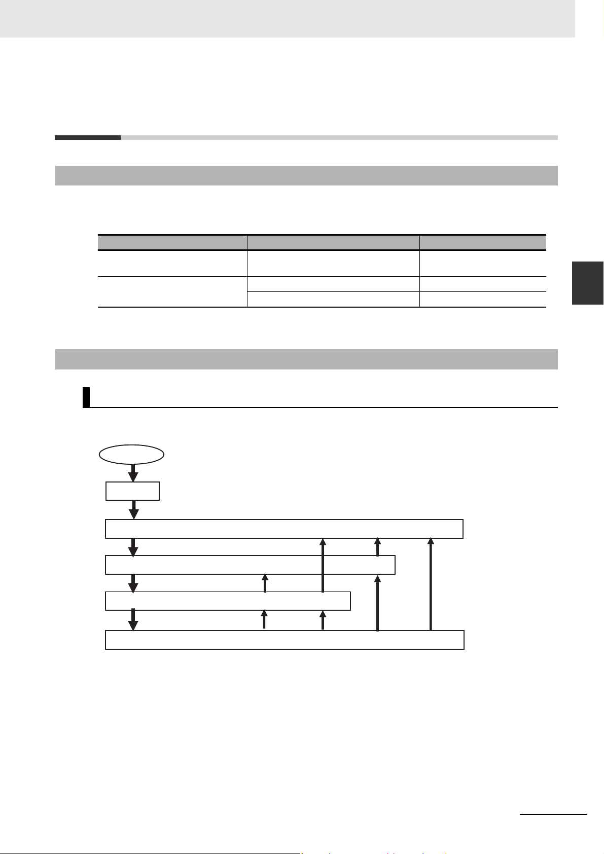
3 EtherCAT Communications
Power ON
Self-diagnosis
4. Operational state (I/O for process data communications and SDO communications are possible.)
3. Safe operational state (Inputs for process data communications and
SDO communications are possible.)
2. Pre-operational state (Only SDO communications is possible.)
1. Init state (Process data communications and SDO communications are not possible.)
3-3 State Transitions for EtherCAT
Communications
3-3-1 Self Diagnosis at Startup
The EtherCAT master executes the following self-diagnosis when the power is turned ON.
The results of self-diagnosis are provided in the following system-defined variables as EtherCAT master errors if errors are detected.
Diagnosis Detected error type System-defined variables
Diagnosis of network configuration
information
Diagnosis of communications port MAC address error _EC_MacAdrErr
Refer to 9-1 Overview of Errors for details on error types.
Network configuration information error _EC_NetCfgErr
Communications controller error _EC_LanHwErr
3-3 State Transitions for EtherCAT Communications
3
3-3-1 Self Diagnosis at Startup
3-3-2 Control States for EtherCAT Communications
Control State Machine
EtherCAT communications provides four control states. Communications is controlled by moving
between these states.
NJ/NX-series CPU Unit Built-in EtherCAT Port User’s Manual (W505)
After the power is turned ON, the communications master and slaves go from the Init state to the Preoperational state, Safe-operational state, and then Operational state before starting EtherCAT communications. Afterwards, EtherCAT communications are performed while the state changes automatically
between these states according to error occurrence and other conditions.
3-9
Page 70

3 EtherCAT Communications
The current control state can be determined using the RUN indicator on the front panel.
State Description
1. Init Communications are
being initialized. Communications are not
possible.
This state continues if
the network is not
configured.
2. Pre-operational Only SDO communications are possible
in this state.
Communications
always enters this
state after initialization, and changes to
the safe-operational
state after initial setting of the network is
performed.
3. Safe operational In this state, SDO
communications and
only inputs for process data communications are possible.
Communications
always enters this
state before going
into the Operational
state.
4. Operational This is the normal
state for communications.
Process data
communications
Not allowed Not allowed Not lit
Not allowed Possible Flashing
Only inputs are
possible
Possible Possible Lit
Possible Flashing
SDO
communications
RUN indicator
3-10
NJ/NX-series CPU Unit Built-in EtherCAT Port User’s Manual (W505)
Page 71

3 EtherCAT Communications
Additional Information
START
I/O refreshing started
for the relevant slave.
User program executed.
Applicable slave
parameters can be set.
5. When the system-defined variable _EC_PDSlavTbl for the
relevant slave changes to TRUE, I/O refreshing for the relevant
slave is enabled.
4. When the system-defined variable _EC_MBXSlavTbl for the
relevant slave changes to TRUE, message communications for
the relevant slave are possible.
3. The program waits for slaves to join the EtherCAT network.
2. Slaves initialized based on network configuration information.
1. EtherCAT master initialized.
Power ON
I/O Refreshing
The procedure from startup of the EtherCAT network until process data I/O can be refreshed is
shown below. There is no correlation between the startup of the EtherCAT network and the execution of the user program. Design the user program by adding the system-defined variables* for
the relevant slaves to the interlock conditions of the device variables for the slaves.
* _EC_ActSlavTbl[1..n], _EC_MBXSlavTbl[1..n], _EC_PDSlavTbl[1..n], _EC_DisconnSlavTbl[1..n], and
_EC_DisableSlavTbl[1..n]
Here, n is the maximum value of the settable node address. Refer to 1-3-1 Performance Specifications for
the maximum value of the settable node address.
3-3 State Transitions for EtherCAT Communications
3
3-3-3 CPU Unit Status in Relation to EtherCAT
3-3-3 CPU Unit Status in Relation to EtherCAT
Refer to A-1 EtherCAT Status in Relation to CPU Unit Status for details on the following: memory
related to the EtherCAT master, the ability to download master settings and slave settings, and the status of slaves according to the CPU Unit operating mode and the status of Controller errors.
NJ/NX-series CPU Unit Built-in EtherCAT Port User’s Manual (W505)
3-11
Page 72

3 EtherCAT Communications
3-12
NJ/NX-series CPU Unit Built-in EtherCAT Port User’s Manual (W505)
Page 73

EtherCAT Network Wiring
This section describes how to connect and wire an EtherCAT network.
4-1 Laying the EtherCAT Network . . . . . . . . . . . . . . . . . . . . . . . . . . . . . . . . . . . . 4-2
4-1-1 Supported Network Topologies . . . . . . . . . . . . . . . . . . . . . . . . . . . . . . . . . . . . 4-2
4-1-2 Installation Precautions . . . . . . . . . . . . . . . . . . . . . . . . . . . . . . . . . . . . . . . . . . 4-4
4-1-3 Installing EtherCAT Communications Cables . . . . . . . . . . . . . . . . . . . . . . . . . 4-4
4-1-4 Connecting Communications Cables . . . . . . . . . . . . . . . . . . . . . . . . . . . . . . . . 4-8
4-1-5 Cable Connection Procedure . . . . . . . . . . . . . . . . . . . . . . . . . . . . . . . . . . . . . . 4-9
4
NJ/NX-series CPU Unit Built-in EtherCAT Port User’s Manual (W505)
4-1
Page 74

4 EtherCAT Network Wiring
Junction Slave
Output port
Input port
Remote I/O SlaveServo Drive Slave
Servo Drive SlaveServo Drive Slave
Servo Drive Slave
Remote I/O Slave
Servo Drive Slave
Remote I/O Slave
Remote I/O Slave
Junction Slave
Remote I/O Slave
Junction Slave
EtherCAT Master
4-1 Laying the EtherCAT Network
This section describes how to install EtherCAT networks.
4-1-1 Supported Network Topologies
The NJ/NX-series CPU Unit can be connected using daisy chain connections with no branching, or with
branching connections using Junction Slaves. This supports redundancy, and all topologies other than
rings. Examples of topology without branching and with branching (Junction Slaves) are shown below.
No Branching
EtherCAT Master
Remote I/O Slave
Remote I/O Slave
Branching
Servo Drive Slave
Remote I/O Slave
Output port
Input port
4-2
NJ/NX-series CPU Unit Built-in EtherCAT Port User’s Manual (W505)
Page 75

4 EtherCAT Network Wiring
Precautions for Safe Use
Precautions for Correct UsePrecautions for Correct Use
Additional Information
You cannot use standard Ethernet hubs or repeater hubs with EtherCAT communications. If you
use one of these, a major fault level error or other error may occur.
When you use a system configuration in which an EtherCAT Junction Slave is connected to synchronized slaves that support distributed clocks, you need a master or slave that can provide a
reference clock.
With the NX-series CPU Unit, the EtherCAT master provides a reference clock.
With the NJ-series CPU Unit, at least one of the following two conditions must be met because
the EtherCAT master does not provide a reference clock.
• A slave that provides a reference clock must be connected between the EtherCAT master and
the first EtherCAT Junction Slave.
• The EtherCAT Junction Slave must provide a reference clock.
However, the above conditions do not apply when synchronization is not performed between
slaves that support providing a distributed clock in the entire EtherCAT network.
You can determine whether the EtherCAT Junction Slave supports a reference clock from the
Reference Clock setting in the Sysmac Studio slave settings. OMRON EtherCAT Junction
Slaves support a reference clock.
4-1 Laying the EtherCAT Network
4
4-1-1 Supported Network Topologies
If you use EtherCAT Junction Slaves, the EtherCAT Junction Slave ports that are actually connected to slaves will communicate normally even if they do not agree with the Sysmac Studio
network configuration.
If you need to make the Sysmac Studio network configuration consistent with the ports that are
actually connected to slaves, use the compare and merge function of the Sysmac Studio to
check the actual configuration.
NJ/NX-series CPU Unit Built-in EtherCAT Port User’s Manual (W505)
4-3
Page 76

4 EtherCAT Network Wiring
4-1-2 Installation Precautions
Basic precautions for the installation of EtherCAT networks are provided below.
Precautions when Installing a Network
• When you install an EtherCAT network, take sufficient safety precautions and perform the installation
according to standards and specifications. (Refer to JIS X5252 or to electrical facility technical references.)
An expert well versed in safety measures and the standards and specifications should be asked to
perform the installation.
• Do not install EtherCAT network equipment near sources of noise. If the network must be installed in
an area with noise, take steps to address the noise, such as placing equipment in metal cases.
• When using a shielded cable with the shields on both ends of the cable connected to connector
hoods, ground loops induced by improper earthing methods may decrease noise immunity and
cause device damage. To prevent ground loops caused by differences in potential between device
earthing points, the reference potential between the devices must be stabilized. Design earthing
appropriately so that noise current does not flow to ground lines between the devices. For earthing
methods, refer to the NJ-series CPU Unit Hardware User’s Manual (Cat. No. W500), the NX-series
CPU Unit Hardware User’s Manual (Cat. No. W535) and the NX-series NX1P2 CPU Unit Hardware
User’s Manual (Cat. No. W578).
Precautions when Installing Communications Cables
• Check the following items on the communications cables that are used in the network.
• Are there any breaks?
• Are there any shorts?
• Are there any connector problems?
• When you connect the cable to the communications connectors on devices, firmly insert the commu-
nications cable connector until it locks in place.
• Do not lay the communications cables together with high-voltage lines.
• Do not lay the communications cable near devices that generate noise.
• Do not lay the communications cables in locations subject to high temperatures or high humidity.
• Do not lay the communications cables in locations subject to excessive dirt and dust or to oil mist or
other contaminants.
• There are limitations on the bending radius of communications cables. Check the specifications of
the communications cable for the bending radius.
4-1-3 Installing EtherCAT Communications Cables
Ethernet communications cables and connectors are used to connect the built-in EtherCAT port with
EtherCAT slaves.
Use a straight, shielded twisted-pair cable (double shielding with aluminum tape and braiding) of Ethernet category 5 (100BASE-TX) or higher.
4-4
NJ/NX-series CPU Unit Built-in EtherCAT Port User’s Manual (W505)
Page 77

4 EtherCAT Network Wiring
Cable with Connectors
Sizes and Conductor Pairs: AWG 27 × 4 Pairs
Product name Manufacturer Cable length [m] Model Contact information
OMRON Cor-
Standard type
Cable with Connectors on Both Ends
(RJ45/RJ45)
Cable Sheath mate-
rial: LSZH
Cable color: Yellow
*1 Cables are available in the following lengths: 0.2, 0.3, 0.5, 1, 1.5, 2, 3, 5, 7.5, 10, 15, and 20 m. Refer to the
Industrial Ethernet Connectors Catalog (Cat. No. G019) for details.
*2 The lineup features Low Smoke Zero Halogen cables for in-cabinet use and PUR cables for out-of-cabinet use.
Although the LSZH cable is single shielded, its communications and noise characteristics meet the standards.
*3 Cables colors are available in blue, yellow, or green.
*1
*2
poration
*3
0.3 XS6W6LSZH8SS30CM-Y
0.5 XS6W6LSZH8SS50CM-Y
1 XS6W-
6LSZH8SS100CM-Y
2 XS6W-
6LSZH8SS200CM-Y
3 XS6W-
6LSZH8SS300CM-Y
5 XS6W-
6LSZH8SS500CM-Y
OMRON Customer
Service Center
4-1 Laying the EtherCAT Network
4
4-1-3 Installing EtherCAT Communications Cables
Sizes and Conductor Pairs: AWG 22 × 2 Pairs
Cable
length
[m]
0.3 XS5W-T421-AMD-K OMRON Cus-
0.5 XS5W-T421-BMD-K
1 XS5W-T421-CMD-K
2 XS5W-T421-DMD-K
5 XS5W-T421-GMD-K
10 XS5W-T421-JMD-K
0.5 XS5W-T421-BM2-SS
1 XS5W-T421-CM2-SS
2 XS5W-T421-DM2-SS
3 XS5W-T421-EM2-SS
5 XS5W-T421-GM2-SS
10 XS5W-T421-JM2-SS
0.5 XS5W-T421-BMC-SS
1 XS5W-T421-CMC-SS
2 XS5W-T421-DMC-SS
3 XS5W-T421-EMC-SS
5 XS5W-T421-GMC-SS
10 XS5W-T421-JMC-SS
Product name
Rugged type
Cable with Connectors on
Both Ends (RJ45/RJ45)
Cable color: Light blue
Rugged type
Cable with Connectors on
Both Ends (M12 Straight/M12
Straight)
Shield Strengthening cable
Cable color: Black
Rugged type
Cable with Connectors on
Both Ends (M12
Straight/RJ45)
Shield Strengthening cable
Cable color: Black
*1
*2
*2
Manu-
facturer
OMRON
Corporation
OMRON
Corporation
OMRON
Corporation
Model
Contact infor-
mation
tomer Service
Center
NJ/NX-series CPU Unit Built-in EtherCAT Port User’s Manual (W505)
4-5
Page 78

4 EtherCAT Network Wiring
Precautions for Correct UsePrecautions for Correct Use
Additional Information
*1 Cables are available in the following lengths: 0.3, 0.5, 1, 2, 3, 5, 10, and 15 m. Refer to the Industrial Ethernet
Connectors Catalog (Cat. No. G019) for details.
*2 For details, contact your OMRON representative.
Cables and Connectors
Sizes and Conductor Pairs: AWG 24 × 4 Pairs
Part name Manufacturer Model Contact information
Cables Hitachi Metals, Ltd. NETSTAR-C5E SAB
RJ45 Connectors Panduit Corporation MPS588* Panduit Corporation US
Planning Department,
0.5 × 4P*
Kuramo Electric Co. KETH-SB* Kuramo Electric Co.
SWCC Showa Cable Systems Co.
FAE-5004* SWCC Showa Cable Sys-
Kanetsu Co., Ltd.
tems Co.
Headquarters
* We recommend that you use combinations of the above Cables and Connectors.
Sizes and Conductor Pairs: AWG 22 × 2 Pairs
Part name Manufacturer Model Contact information
Cables Kuramo Electric Co. KETH-PSB-OMR* Kuramo Electric Co.
JMACS Japan Co., Ltd. PNET/B* JMACS Japan Co., Ltd.
RJ45 Assembly Connectors
* We recommend that you use combinations of the above Cables and Connectors.
• The maximum length between nodes is 100 m. However, some cables are specified for less
than 100 m. Generally speaking, if the conductors are twisted wire rather than solid wire,
transmission performance will be lower, and reliable communications may not be possible at
100 m. Confirm details with the cable manufacturer.
• When selecting a connector, confirm that it is applicable to the cable that will be used. Confirm
the following items: Conductor size, conductor type (solid wire or twisted wire), number of
twisted pairs (2 or 4), outer diameter, etc.
OMRON Corporation XS6G-T421-1* OMRON Customer Ser-
vice Center
If an Ethernet cable of category 5 or higher is used, communications will be possible even if the
cable is not shielded. However, we recommend a cable with double, aluminum tape and braided
shielding to ensure sufficient noise immunity.
4-6
NJ/NX-series CPU Unit Built-in EtherCAT Port User’s Manual (W505)
Page 79

4 EtherCAT Network Wiring
1
2
3
4
5
6
7
8
1
2
3
4
5
6
7
8
Shield
Shield
White-BrownWhite-Brown
BlueBlue
White-Orange
White-Orange
Brown Brown
HoodHood
Orange Orange
White-Blue White-Blue
Green
Green
Wire colorWire color
White-Green White-Green
Pin No. Pin No.
Attaching the Connectors to the Cable and Pin Assignments
Use straight wiring to attach the connectors to the communications cable.
*1 Connect the cable shield to the connector hood at both ends of the cable.
*2 There are two connection methods for Ethernet: T568A and T568B. The T568A connection method is shown
above, but the T568B connection method can also be used.
4-1 Laying the EtherCAT Network
4
Connector Specifications
Specification Description
Electrical characteristics Conforms to IEEE 802.3 standards.
Connector structure RJ45 8-pin modular connector (Conforms to ISO 8877.)
Pin Assignments
Pin No. Signal name Abbreviation Signal direction
1 Transmission data + TD+ Output
2 Transmission data − TD− Output
3 Reception data + RD+ Input
4 Not used. --- ---
5 Not used. --- --6 Reception data − RD− Input
7 Not used. --- ---
8 Not used. --- ---
Hood Frame ground FG ---
4-1-3 Installing EtherCAT Communications Cables
NJ/NX-series CPU Unit Built-in EtherCAT Port User’s Manual (W505)
4-7
Page 80

4 EtherCAT Network Wiring
Precautions for Correct UsePrecautions for Correct Use
Additional Information
4-1-4 Connecting Communications Cables
Cable connections can be made freely in EtherCAT networks. Connect the communications cable from
the EtherCAT master to the input port on the first slave, and then connect the communications cable to
the next slave to the output port on the first slave.
Do not connect anything to the output port of the slave at the end of the network.
EtherCAT master
Communications cable
Input port
L1
Output port
L2
Slaves
Ln
Do not connect anything
Last slave
The cable between any two nodes (L1, L2 ... Ln) must be 100 m or less. Use the Sysmac Studio to confirm if communications are possible for the total cable length. Firmly connect the communications cable
connector until it clicks into place.
Always perform one of the following operations before you disconnect the communications cable
to a EtherCAT slave during operation.
• Disconnect the EtherCAT slave from the network.
• Disable the EtherCAT slaves and all slaves connected after it.
Refer to 9-4 Replacing Slaves during Communications for information on replacing slaves during
operation.
Make sure the cable between each pair of devices connects an output port to an input port. Normal communications are not possible if an output port is connected to another output port or an
input port is connected to another input port.
4-8
NJ/NX-series CPU Unit Built-in EtherCAT Port User’s Manual (W505)
Page 81

Precautions for Correct UsePrecautions for Correct Use
4-1-5 Cable Connection Procedure
CPU Unit
RJ45 Modular Connector
Built-in EtherCAT port
• Turn OFF the Controller’s power supply before connecting or disconnecting Ethernet communications cable.
• Allow extra space for the bending radius of the communications cable. The required space
depends on the communications cable, connector, and CPU Unit that are used. Refer to the
NJ-series CPU Unit Hardware User’s Manual (Cat. No. W500) for details on the NJ-series
CPU Unit. Refer to the NX-series CPU Unit Hardware User’s Manual (Cat. No. W535) for
details on the NX701 CPU Unit.
Refer to the NX-series NX1P2 CPU Unit Hardware User’s Manual (Cat. No. W578) for details
on the NX1P2 CPU Unit.
1
Lay the Ethernet communications cable.
2
Connect the Ethernet communications cable to the built-in EtherCAT port on the NJ/NX-series
CPU Unit. Firmly insert the connector until it locks into place.
4 EtherCAT Network Wiring
4-1 Laying the EtherCAT Network
4
4-1-5 Cable Connection Procedure
NJ/NX-series CPU Unit Built-in EtherCAT Port User’s Manual (W505)
4-9
Page 82

4 EtherCAT Network Wiring
4-10
NJ/NX-series CPU Unit Built-in EtherCAT Port User’s Manual (W505)
Page 83

Setting Up EtherCAT
Communications with the Sysmac
Studio
This section describes how to set the network configuration information and how to
check EtherCAT communications from the Sysmac Studio.
5-1 Overview of Network Configuration Information . . . . . . . . . . . . . . . . . . . . 5-2
5-2 Creating the EtherCAT Network Configuration . . . . . . . . . . . . . . . . . . . . . . 5-3
5-3 Setting EtherCAT Slave Variables and Axes . . . . . . . . . . . . . . . . . . . . . . . . 5-6
5-3-1 Registering Device Variables for All EtherCAT Slaves . . . . . . . . . . . . . . . . . . 5-6
5-3-2 Axis Settings for Servo Drives and Encoder Input Slaves . . . . . . . . . . . . . . . 5-10
5-4 EtherCAT Master and Slave Parameter Settings . . . . . . . . . . . . . . . . . . . . 5-11
5-4-1 Setting EtherCAT Master . . . . . . . . . . . . . . . . . . . . . . . . . . . . . . . . . . . . . . . . .5-11
5-4-2 Setting EtherCAT Slaves . . . . . . . . . . . . . . . . . . . . . . . . . . . . . . . . . . . . . . . . 5-16
5-5 Comparing and Merging EtherCAT Network Configurations . . . . . . . . . . 5-24
5-5-1 Comparing and Merging with the Actual Network Configuration
from the Sysmac Studio . . . . . . . . . . . . . . . . . . . . . . . . . . . . . . . . . . . . . . . . . 5-24
5-5-2 Automatically Creating the Network Configuration . . . . . . . . . . . . . . . . . . . . 5-28
5-5-3 Using the Sysmac Studio to Obtain Serial Numbers
from the Actual Network Configuration . . . . . . . . . . . . . . . . . . . . . . . . . . . . . 5-31
5-6 Downloading the Network Configuration Information . . . . . . . . . . . . . . . 5-33
5-6-1 Downloading the Network Configuration Information from
the Sysmac Studio . . . . . . . . . . . . . . . . . . . . . . . . . . . . . . . . . . . . . . . . . . . . . 5-33
5-7 Confirming Communications after Completing EtherCAT
Configuration and Settings . . . . . . . . . . . . . . . . . . . . . . . . . . . . . . . . . . . . . 5-35
5
NJ/NX-series CPU Unit Built-in EtherCAT Port User’s Manual (W505)
5-1
Page 84

5 Setting Up EtherCAT Communications with the Sysmac Studio
Wait Time for Slave
Startup
EtherCAT
The network configuration information is
downloaded.
PDO data for
Servo Drive slaves
PDO data for
EtherCAT slaves
Process Data Information
Slaves
Master
EtherCAT Master
Parameter Settings
EtherCAT network configuration
Network Configuration Information
EtherCAT master
Sysmac Studio
NJ/NX-series CPU Unit
Etc.
Fail-soft Operation
Setting
5-1 Overview of Network Configuration
Information
To execute EtherCAT communications, you must create the following three types of data with the Sysmac Studio and download the data to the CPU Unit. When this data is set, the network configuration
information is automatically created.
When you download the network configuration information to the CPU Unit, the EtherCAT master initializes slaves and performs process data communications based on the network configuration information. This section describes the procedures to set the network configuration information and how to
check EtherCAT communications.
Network Configuration Information
Network configuration information
1. EtherCAT network configuration
2. Process data information
This is allocation information for PDO data in the slaves. It is also called PDO
mapping data.
3. EtherCAT master and slave parameter settings
(Examples: Fail-soft Operation Setting and Wait Time for Slave Startup)
5-2
NJ/NX-series CPU Unit Built-in EtherCAT Port User’s Manual (W505)
Page 85

5 Setting Up EtherCAT Communications with the Sysmac Studio
Double-click EtherCAT or rightclick EtherCAT and select Edit.
Multi-view Explorer
Edit Pane
5-2 Creating the EtherCAT Network
Configuration
This section describes how to create the EtherCAT network configuration.
1
Start the Sysmac Studio offline.
2
Double-click EtherCAT under Configurations and Setup on the Multiview Explorer. Or, right-
click EtherCAT under Configurations and Setup and select Edit.
5-2 Creating the EtherCAT Network Configuration
EtherCAT master will be displayed in the Edit Pane.
5
NJ/NX-series CPU Unit Built-in EtherCAT Port User’s Manual (W505)
5-3
Page 86

5 Setting Up EtherCAT Communications with the Sysmac Studio
Toolbox
Drag the slaves.
3
Select a slave in the Toolbox, drag it to the Edit Pane, and drop it under the master. The slave
will be added under the master.
4
Select another slave in the Toolbox, drag it to the Edit Pane, and drop it under the slave to which
you want to connect it to. The slave will be added under the slave.
For detailed procedures, such as those for deleting slaves, or copying and pasting slaves, refer
to the Sysmac Studio Version 1 Operation Manual (Cat. No. W504).
Refer to the NX-series EtherCAT Coupler Unit User’s Manual (Cat. No. W519) and the Sysmac
Studio Version 1 Operation Manual (Cat. No. W504) for information on creating the EtherCAT
Slave Terminal configuration.
5-4
Refer to A-8 MDP Settings for EtherCAT Network Slaves in the Sysmac Studio Version 1 Oper-
ation Manual (Cat. No. W504) for information on MDP slaves and editing the configurations of
the modules that you can connect to the MDP slaves.
NJ/NX-series CPU Unit Built-in EtherCAT Port User’s Manual (W505)
Page 87

5 Setting Up EtherCAT Communications with the Sysmac Studio
Additional Information
You can go online and read the actual network configuration from the Sysmac Studio to display it
and to use it as the network configuration in the project.
For details, refer to 5-5-2 Automatically Creating the Network Configuration.
5-2 Creating the EtherCAT Network Configuration
5
NJ/NX-series CPU Unit Built-in EtherCAT Port User’s Manual (W505)
5-5
Page 88

5 Setting Up EtherCAT Communications with the Sysmac Studio
5-3 Setting EtherCAT Slave Variables and
Axes
Device variables are used to read and write process data for EtherCAT slaves. Axis variables are used
to manipulate slaves to which axes are assigned from the Motion Control Function Module. This section
describes how to register device variables and set the axes.
5-3-1 Registering Device Variables for All EtherCAT Slaves
You use the I/O Map Tab Page in the Sysmac Studio to assign device variables to the I/O ports. The
device variables that you create are registered in the global variable table.
Use one of the following three methods.
• Selecting variables that were previously registered in a variable table
• Inputting new device variable names
• Automatically creating device variable names
Selecting Variables That Were Previously Registered in a Variable Table
You can select variables that are already registered on the menu on the I/O Map Tab Page. For example, this method can be used to register device variables in the following cases.
• To write the program before the slave configuration information is created.
• To reuse programming from another project.
Use the following procedure.
1
Register the variables in advance in the global variable table or the local variable table of one of
the POUs.
2
Program using those variables.
3
Create the slave configuration information.
4
Double-click I/O Map under Configurations and Setup on the Multiview Explorer. Or, rightclick I/O Map under Configurations and Setup and select Edit.
5-6
NJ/NX-series CPU Unit Built-in EtherCAT Port User’s Manual (W505)
Page 89

5 Setting Up EtherCAT Communications with the Sysmac Studio
5
Select the variables from the pull-down list in the I/O Map Tab Page to assign them to I/O ports.
Select user-defined variables that were previously
registered in the global variable table.
Inputting New Device Variable Names
5-3 Setting EtherCAT Slave Variables and Axes
You can input the required device variable names. For example, this method can be used to register
device variables in the following case.
• To give suitable names to device variables that are assigned to I/O for I/O slaves.
Use the following procedure.
1
Double-click I/O Map under Configurations and Setup on the Multiview Explorer. Or, rightclick I/O Map under Configurations and Setup and select Edit.
2
Select the I/O port on the I/O Map Tab Page and enter the variable name in the Variable Column.
5
5-3-1 Registering Device Variables for All EtherCAT Slaves
Device variables are assigned to the I/O ports of the slaves.
NJ/NX-series CPU Unit Built-in EtherCAT Port User’s Manual (W505)
5-7
Page 90

5 Setting Up EtherCAT Communications with the Sysmac Studio
3
To specify a variable table for the scope, specify the Variable Type.
Automatically Creating Device Variable Names
The device variable names will be created by combining the device name and the I/O port name. The
device names are set in the slave parameters. The default device names are “E” followed by a serial
number that starts from 001. For example, this method can be used to register device variables in the
following case.
• To eliminate the work that is involved in obtaining the device variable names.
Use the following procedure.
1
Double-click I/O Map under Configurations and Setup on the Multiview Explorer. Or, rightclick I/O Map under Configurations and Setup and select Edit.
5-8
The I/O Map Tab Page will be displayed.
NJ/NX-series CPU Unit Built-in EtherCAT Port User’s Manual (W505)
Page 91

5 Setting Up EtherCAT Communications with the Sysmac Studio
Device variables that were automatically created
2
Select a slave or I/O ports on the I/O Map Tab Page, right-click, and select Create Device Variable.
5-3 Setting EtherCAT Slave Variables and Axes
3
If you specify a variable table for the scope, specify the Variable Type afterward.
Device variables are automatically assigned to the I/O ports of the slaves and registered in the
variable table that is specified by the variable type.
5
5-3-1 Registering Device Variables for All EtherCAT Slaves
NJ/NX-series CPU Unit Built-in EtherCAT Port User’s Manual (W505)
5-9
Page 92

5 Setting Up EtherCAT Communications with the Sysmac Studio
Additional Information
• We recommend that you set device names.
• To delete the mapping for the variable that is assigned to a port, delete the contents of the cell
in the Variable Column or right-click the cell and select Reset Assignment.
The mapping of the device variable is deleted. The variable is not deleted from the variable
table.
Refer to NJ/NX-series CPU Unit Software User’s Manual (Cat. No. W501) for details on device
variables.
• If you do not specify anything in the Variable Type Column when you register a variable or cre-
ate device variables, the variables are automatically registered in the global variable table.
5-3-2 Axis Settings for Servo Drives and Encoder Input Slaves
To operate slaves that can be assigned to axes in the Motion Control Function Module, you have to
make axes settings. For details on the items and procedures of the axes setting, refer to the NJ/NX-
series CPU Unit Motion Control User's Manual (Cat. No. W507).
5-10
NJ/NX-series CPU Unit Built-in EtherCAT Port User’s Manual (W505)
Page 93

5 Setting Up EtherCAT Communications with the Sysmac Studio
5-4 EtherCAT Master and Slave
Parameter Settings
5-4-1 Setting EtherCAT Master
1
Double-click EtherCAT under Configurations and Setup on the Multiview Explorer. Or, right-
click EtherCAT under Configurations and Setup and select Edit.
5-4 EtherCAT Master and Slave Parameter Settings
2
Select the EtherCAT master that is displayed in the Edit Pane.
• Screen for NJ-series CPU Unit
5
5-4-1 Setting EtherCAT Master
NJ/NX-series CPU Unit Built-in EtherCAT Port User’s Manual (W505)
5-11
Page 94

5 Setting Up EtherCAT Communications with the Sysmac Studio
• Screen for NX-series CPU Unit
The EtherCAT master settings are listed below.
Name Editing Remarks
Device name OK Displays the name of the EtherCAT master.
Default setting: Master
Model name Not
allowed.
Product name Not
allowed.
Number of Slaves Not
allowed.
PDO Communications Cycle
*2
Not
allowed.
*3
PDO Communications Cycle 1
Not
allowed.
*3
PDO Communications Cycle 2
Not
allowed.
Reference Clock Not
allowed.
Total Cable Length
*7
OK This is the total cable length between the slaves.
Always ”Master.”
Always ”Master.”
The number of slaves is automatically calculated based on the
topology.
Display range: 0 to the maximum number of slaves.
Displays the time of Process Data Communications Cycle.
This is automatically input based on the task period of the primary periodic task.
Display range: 500 to 4,000 μs.
Default setting: 1,000 μs
Displays the time of Process Data Communications Cycle 1.
This is automatically input based on the task period of the primary periodic task.
Display range: 125, 250 to 8,000 μs.
Default setting: 1,000 μs
*4
Displays the time of Process Data Communications Cycle 2.
This is automatically input based on the task period of the priority-5 periodic task.
*5
Display range: 125, 250 to 100,000 μs.
Default setting: 2,000 μs
Displays whether the master provides a reference clock.
Exist: The master provides a reference clock.
Not Exist: The master does not provides a reference clock.
Default setting: 1,000 m
*1
*6
5-12
NJ/NX-series CPU Unit Built-in EtherCAT Port User’s Manual (W505)
Page 95

5 Setting Up EtherCAT Communications with the Sysmac Studio
Name Editing Remarks
Fail-soft Operation Setting OK Select Stop or Fail-soft operation for communications with all
slaves on the network when the master detects a communications error (cable disconnection, slave malfunction, etc.).
Default setting: Fail-soft operation
Refer to 9-1 Overview of Errors for details on errors.
Wait Time for Slave Startup OK Set the time to wait from the detection of the link on the Ether-
CAT port until all slaves join the network.
Setting range: 3 to 200 s
Default setting: 30 s
Process data communications start if all slaves are present
within the wait time. If all of the slaves are not present after the
wait time elapses, a Network Configuration Verification Error
occurs.
When you use a slave that takes time to start, use a longer wait
time setting to prevent errors.
PDO Communications Timeout
Detection Count
Revision Check Method OK Specify the method to use to verify the revision numbers that
Serial Number Check Method
DC Synchronous Correction
*10
OK A Process Data Reception Timeout error occurs if process data
(PDO) communications timeouts occur continuously more
often than the specified number of times.
Increase the setting if Process Data Reception Timeout errors
occur frequently, such as in high-noise environments.
Set the value to 2 or higher for a slave that needs to be
replaced.
Setting range: 1 to 8 errors
Default setting: 2 errors
are stored in the network configuration information (setting)
against the actual revision numbers of the slaves (actual
device) at the start of communications.
Communications will not start if there are unverified slaves,
and a Network Configuration Verification Error will occur.
Setting values: Setting <= Actual device, Setting = Actual
device, or No check
Default setting: Setting <= Actual device
*9
OK Specify whether to verify the slave serial numbers that are
stored in the network configuration information against the
serial numbers that are set in the actual slaves when initiating
communications.
Communications will not start if there are unverified slaves,
and a network configuration verification error will occur.
Setting values: Setting = Actual device or No check
Default setting: No check
OK Specify whether to use the slave monitoring option during DC
Synchronous Correction which ensures sync jitter accuracy of
the DC time.
If Enable slave monitoring option is selected, the master executes DC Synchronous Correction while monitoring the DC
time of the slave.
Use this setting if a Slave Application Error occurs when the
slaves are started. The error can be prevented if you select
Enable slave monitoring option and reconnect the slave. If the
error does not occur any more, that means a longer time is
required for the startup of all slaves and slave reconnection.
Setting range: Enable, or Disable slave monitoring option
Default setting: Disable slave monitoring option
*8
5-4 EtherCAT Master and Slave Parameter Settings
5
5-4-1 Setting EtherCAT Master
*1 Refer to 1-3-1 Performance Specifications for the maximum number of slaves.
NJ/NX-series CPU Unit Built-in EtherCAT Port User’s Manual (W505)
5-13
Page 96

5 Setting Up EtherCAT Communications with the Sysmac Studio
Precautions for Safe Use
Additional Information
*2 Displayed only with the NJ-series CPU Unit.
*3 Displayed only with the NX-series CPU Unit.
*4 For the NX1P2 CPU Unit, the default setting is 2,000 μs.
*5 When the priority-5 periodic task is not used, “---” is displayed.
*6 Exist is displayed with the NX-series CPU Unit, Not Exist is displayed with the NJ-series.
*7 If the total cable length exceeds the default setting (1,000 m), set an appropriate value for the total cable
length.
*8 Refer to the following table, Communications with Slaves Based on the Result of Revision Number Check, for
the operation of communications with slaves that are determined by the result of revision number check.
*9 If the set value is Setting = Actual device, communications are not started with a slave, in a network, that is
replaced. If it is necessary to replace a slave while the set value is Setting = Actual device, you must correct
the network configuration information and transfer it to the EtherCAT master again. Set this parameter to
Setting = Actual device only when strict management of the equipment configuration is required.
*10 A CPU Unit with unit version 1.10 or later and Sysmac Studio version 1.12 or higher are required to use this
function.
Communications with Slaves Based on the Result of Revision Number Check
Setting value of Revision
Check Method
Setting <= Actual device Setting > Actual device Communications are not possible.
Setting = Actual device Setting > Actual device Communications are not possible.
No check Setting > Actual device Communications are possible.
Result of revision number
check
Setting = Actual device Communications are possible.
Setting < Actual device Communications are possible.
Setting = Actual device Communications are possible.
Setting < Actual device Communications are not possible.
Setting = Actual device Communications are possible.
Setting < Actual device Communications are possible.
Communications with slaves
• If the Fail-soft Operation Setting parameter is set to Stop, process data communications will
stop for all slaves when an EtherCAT communications error is detected in a slave. The Servo
Drive will operate according to the Servo Drive specifications. Make sure that the Fail-soft
Operation parameter setting results in safe operation when a device error occurs.
• If verifying revisions is disabled, parameters are also transferred to slaves with different EtherCAT revisions. If an incompatible revision of a slave is connected, incorrect parameters may
be set and operation may not be correct. If you disable the revision check, make sure that only
compatible slaves are connected before transferring the parameters.
Network Configuration Verification
The network configuration information is verified against the actual network when the EtherCAT
master is started. If an inconsistency is found during verification, the system-defined variable for
a Network Configuration Verification Error provides notification.
This setting applies to the entire system and cannot be changed for individual slaves.
5-14
NJ/NX-series CPU Unit Built-in EtherCAT Port User’s Manual (W505)
Page 97

5 Setting Up EtherCAT Communications with the Sysmac Studio
Verified information Required/optional Description
Number of slaves connected Required Number of slaves in the network
Vendor ID Required Vendor ID of each slave
Product code Required Product code of each slave
Revision
Serial number
*1 Options are available.
*2 Serial number verification is performed for all slaves in the EtherCAT topology. You cannot specify dif-
ferent verification methods for individual slaves. The default setting is No check.
Optional
Optional
*1
*1*2
Revision number of each slave
Serial numbers of all slaves
5-4 EtherCAT Master and Slave Parameter Settings
5
5-4-1 Setting EtherCAT Master
NJ/NX-series CPU Unit Built-in EtherCAT Port User’s Manual (W505)
5-15
Page 98

5 Setting Up EtherCAT Communications with the Sysmac Studio
5-4-2 Setting EtherCAT Slaves
1
Double-click EtherCAT under Configurations and Setup on the Multiview Explorer. Or, right-
click EtherCAT under Configurations and Setup and select Edit.
2
Select an EtherCAT slave that is displayed in the Edit Pane.
• Screen for NJ-series CPU Unit
5-16
NJ/NX-series CPU Unit Built-in EtherCAT Port User’s Manual (W505)
Page 99

5 Setting Up EtherCAT Communications with the Sysmac Studio
• Screen for NX-series CPU Unit
5-4 EtherCAT Master and Slave Parameter Settings
The EtherCAT slave settings are listed as below.
Name Editing Remarks
Device name OK Displays the name of the slave.
Default setting: E*** (where * is a serial number starting
from 001)
The default value is automatically generated based on the
node address.
Model name Not
allowed.
Product name Not
allowed.
Revision Not
allowed.
*1
PDO Communications Cycle
Node Address OK Sets the node address.
Not
allowed.
Automatically displays the name of the slave model.
Displays the product name of the slave.
Displays the revision of the slave.
Displays the process data communications cycle
assigned for the slave.
Either of the following values is displayed.
• PDO Communications Cycle 1
Communications cycle is the task period of the primary periodic task.
• PDO Communications Cycle 2
Communications cycle is the task period of the priority-5 periodic task.
The default value is set automatically when a slave is
added.
Setting range: Settable node address range
5
5-4-2 Setting EtherCAT Slaves
*2
NJ/NX-series CPU Unit Built-in EtherCAT Port User’s Manual (W505)
5-17
Page 100

5 Setting Up EtherCAT Communications with the Sysmac Studio
Name Editing Remarks
Enable/Disable Settings OK Enables or disables the slave as a communications tar-
get.
• Enabled: The slave will operate.
• Disabled: The slave will not operate.
Set the following slaves as disabled slaves: slaves that
are not installed on the physical EtherCAT network but
are scheduled for addition at a later date or slaves that
not used due to changes in the device configuration
during system operation.
Even for disabled slaves, process data allocations can be
set and used as system-defined variables and device
variables in the user program.
Default setting: Enabled
Serial Number Not
allowed.
PDO Map Settings OK Default allocations of process data for slaves are provided
Enable Distributed Clock OK If a slave provides a distributed clock, Enabled is dis-
Displays the serial number of the slave.
Default: 0x00000000 (when offline)
The value is updated to the serial number of the physical
slave when you select Get Slave Serial Numbers from
the menu for the master.
A Network Configuration Verification Error occurs if the
serial number on the Sysmac Studio and the serial number of the physical slave do not agree when the Serial
Number Check Method in the master settings is set to
Setting = Actual device.
Refer to 5-5-3 Using the Sysmac Studio to Obtain Serial
Numbers from the Actual Network Configuration for how
to access the serial number of the physical slave.
by the Sysmac Studio.
When the network configuration is created, device variables are automatically created in the initial process data
allocations. You can read and write these process data
allocations as device variables from the user program.
When valid PDOs are present, a list of them is displayed.
When valid PDOs are not present, “---” is displayed.
If editing the process data allocations is required, click the
Edit PDO Map Settings Button at the bottom of the list.
Refer to Changing the PDO Map Settings for details.
played.
If a slave provides a distribute clock which allows disable
setting, either Enabled or Disabled is displayed. You can
select enabling or disabling the clock.
If the distributed clock is enabled, you can select the synchronization timing (Sync0 or Sync1) for some slaves. If
Sync0 is selected, Enabled (DC Sync0) is displayed.
If a slave does not provide a distributed clock, “---” is displayed.
*3
5-18
NJ/NX-series CPU Unit Built-in EtherCAT Port User’s Manual (W505)
 Loading...