

Page 1
Machine Automation Controller
NJ-series
NJ Robotics CPU Unit
User’s Manual
NJ501-4500
NJ501-4400
NJ501-4320
NJ501-4310
NJ501-4300
CPU Unit
W539-E1-04
Page 2

NOTE
All rights reserved. No part of this publication may be reproduced, stored in a retrieval system, or transmitted, in
any form, or by any means, mechanical, electronic, photocopying, recording, or otherwise, without the prior
written permission of OMRON.
No patent liability is assumed with respect to the use of the information contained herein. Moreover, because
OMRON is constantly striving to improve its high-quality products, the information contained in this manual is
subject to change without notice. Every precaution has been taken in the preparation of this manual. Nevertheless, OMRON assumes no responsibility for errors or omissions. Neither is any liability assumed for damages
resulting from the use of the information contained in this publication.
Trademarks
• Sysmac and SYSMAC are trademarks or registered trademarks of OMRON Corporation in Japan and other
countries for OMRON factory automation products.
• Microsoft, Windows, Windows Vista, Excel, and Visual Basic are either registered trademarks or trademarks of
Microsoft Corporation in the USA and other countries.
• EtherCAT® is registered trademark and patented technology, licensed by Beckhoff Automation GmbH, Germany.
• ODVA, CIP, CompoNet, DeviceNet, and EtherNet/IP are trademarks of ODVA.
• The SD and SDHC logos are trademarks of SD-3C, LLC.
Other company names and product names in this document are the trademarks or registered trademarks of their
respective companies.
Copyrights
Microsoft product screen shots reprinted with permission from Microsoft Corporation.
Page 3

Introduction
Thank you for purchasing an NJ-series NJ Robotics CPU Unit (hereinafter called NJ Robotics CPU
Unit).
This manual contains information that is necessary to use the NJ Robotics CPU Unit. Please read this
manual and make sure you understand the functionality and performance of this product before you
attempt to use it.
When you have finished reading this manual, keep it in a safe location where it will be readily available
for reference during operation.
This manual describes only the functions added to NJ501-4 Units.
Refer to the NJ-series manuals listed in Related Manuals on page 33 for functions which are common
in NJ501- Units including NJ501-1 Units.
Intended Audience
Introduction
This manual is intended for the following personnel, who must also have knowledge of electrical systems (an electrical engineer or the equivalent).
• Personnel in charge of introducing FA systems.
• Personnel in charge of designing FA systems.
• Personnel in charge of installing and connecting FA systems.
• Personnel in charge of managing FA systems and facilities.
For programming, this manual is intended for personnel who understand the programming language
specifications in international standard IEC 61131-3 or Japanese standard JIS B 3503.
Applicable Products
This manual covers the following products.
• NJ-series NJ Robotics CPU Unit
NJ501-4500
NJ501-4400
NJ501-4320
NJ501-4310
NJ501-4300
(Robot Version 1.02 or later)
NJ-series NJ Robotics CPU Unit User’s Manual (W539)
1
Page 4

Relevant Manuals
Relevant Manuals
The following table provides the relevant manuals for this product. Read all of the manuals that are relevant to your system configuration and application to make the most of this product.
Most operations are performed from the Sysmac Studio Automation Software.
Refer to the Sysmac Studio Version 1 Operation Manual (Cat. No. W504) for information on the Sys-
mac Studio.
Basic information
NJ-series CPU Unit
Hardware User’s Manual
Purpose of use
Manual
NJ/NX-series CPU Unit
Software User’s Manual
NJ/NX-series
Instructions Reference Manual
NJ/NX-series CPU Unit
Motion Control User's Manual
NJ/NX-series
Motion Control Instructions Reference Manual
NJ/NX-series CPU Unit
Built-in EtherCAT® Port User’s Manual
NJ/NX-series CPU Unit
Built-in EtherNet/IP™ Port User’s Manual
NJ-series Database Connection CPU Units
User’s Manual
NJ-series NJ Robotics CPU Unit
User's Manual
NJ/NX-series
Troubleshooting Manual
Introduction to NJ-series Controllers
Setting devices and hardware
Using motion control
Using EtherCAT
Using EtherNet/IP
Using database connection service
Using robot control
Software settings
Using motion control
Using EtherCAT
Using EtherNet/IP
Using database connection service
Using robot control
Writing the user program
Using motion control
Using EtherCAT
Using EtherNet/IP
Using database connection service
Using robot control
Programming error processing
Testing operation and debugging
Using motion control
Using EtherCAT
Using EtherNet/IP
Using database connection service
Using robot control
2
NJ-series NJ Robotics CPU Unit User’s Manual (W539)
Page 5

Purpose of use
Basic information
NJ-series CPU Unit
Hardware User’s Manual
NJ/NX-series CPU Unit
Software User’s Manual
NJ/NX-series
Instructions Reference Manual
NJ/NX-series CPU Unit
Motion Control User's Manual
Motion Control Instructions Reference Manual
Manual
NJ/NX-series
Relevant Manuals
NJ/NX-series CPU Unit
Built-in EtherCAT® Port User’s Manual
NJ/NX-series CPU Unit
Built-in EtherNet/IP™ Port User’s Manual
NJ-series Database Connection CPU Units
User’s Manual
NJ-series NJ Robotics CPU Unit
User's Manual
NJ/NX-series
Troubleshooting Manual
Learning about error management and
corrections
Maintenance
Using motion control
Using EtherCAT
Using EtherNet/IP
Using database connection service
Using robot control
*1
*1. Refer to the NJ/NX-series Troubleshooting Manual (Cat. No. W503) for the error management concepts and an overview
of the error items. For details on each error, refer to the relevant manuals indicated with mark.
NJ-series NJ Robotics CPU Unit User’s Manual (W539)
3
Page 6
Manual Structure
4-9
4 Installation and Wiring
NJ-series CPU Unit Hardware User’s Manual (W500)
stinUgnitnuoM3-4
4
stnenopmoCrellortnoCgnitcennoC1-3-4
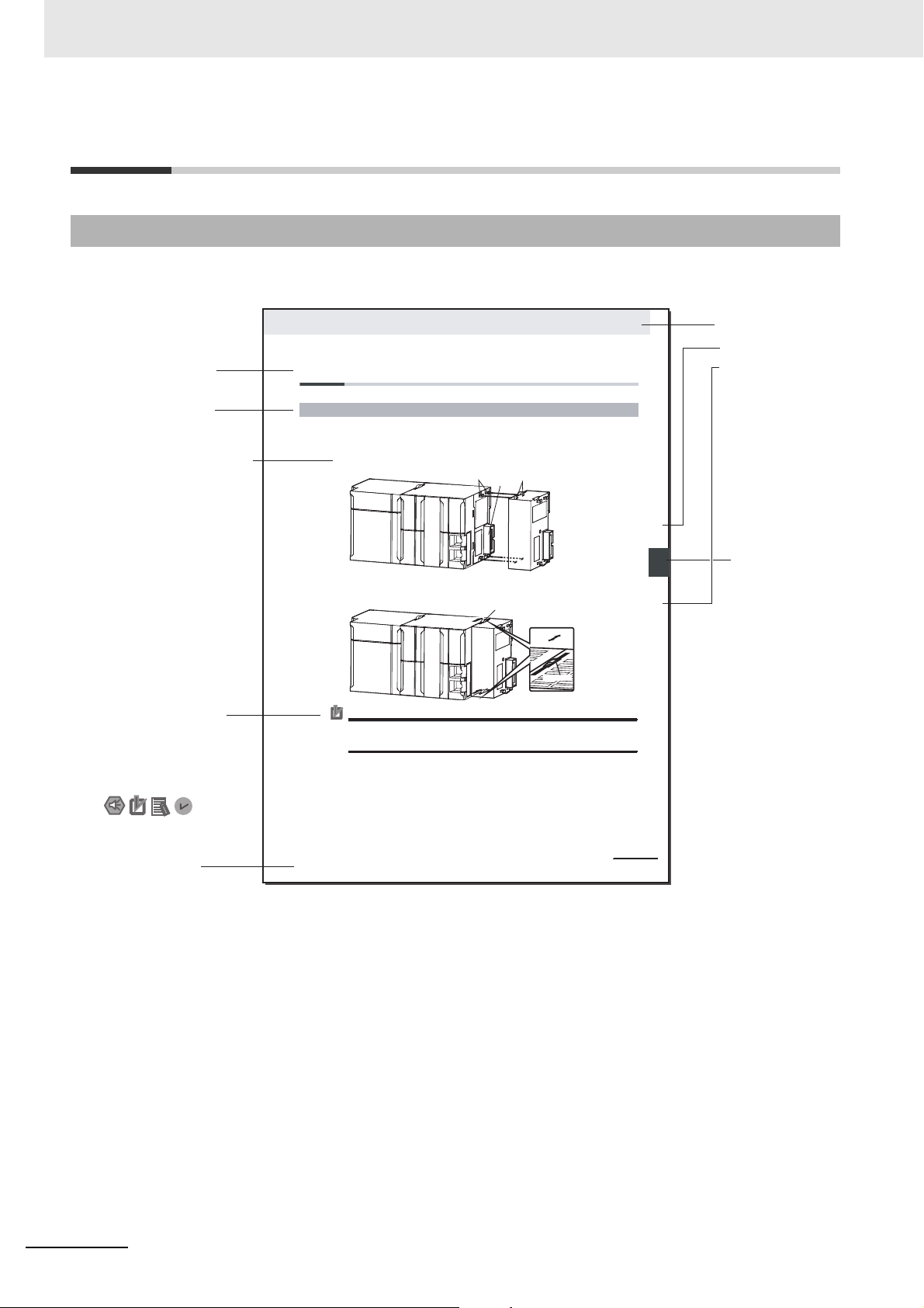
4-3 Mounting Units
The Units that make up an NJ-series Controller can be connected simply by pressing the Units together
and locking the sliders by moving them toward the back of the Units. The End Cover is connected in the
same way to the Unit on the far right side of the Controller.
1 Join the Units so that the connectors fit exactly.
2 The yellow sliders at the top and bottom of each Unit lock the Units together. Move the sliders
toward the back of the Units as shown below until they click into place.
Precautions for Correct UsePrecautions for Correct Use
4-3-1 Connecting Controller Components
Connector
Hook
Hook holes
Slider
Lock
Release
Move the sliders toward the back
until they lock into place.
Level 1 heading
Level 2 heading
Level 3 heading
Level 2 heading
A step in a procedure
Manual name
Special information
Level 3 heading
Page tab
Gives the current
headings.
Indicates a procedure.
Icons indicate
precautions, additional
information, or reference
information.
Gives the number
of the main section
The sliders on the tops and bottoms of the Power Supply Unit, CPU Unit, I/O Units, Special I/O
Units, and CPU Bus Units must be completely locked (until they click into place) after connecting
the adjacent Unit connectors.
Manual Structure
Page Structure and Symbols
The following page structure and symbols are used in this user’s manual.
Note This illustration is provided only as a sample. It may not literally appear in this manual.
4
NJ-series NJ Robotics CPU Unit User’s Manual (W539)
Page 7

Precautions for Safe Use
Precautions for Correct Use
Additional Information
Version Information
Special Information
Special information in this user’s manual is classified as follows:
Precautions on what to do and what not to do to ensure safe usage of the product.
Precautions on what to do and what not to do to ensure proper operation and performance.
Additional information to read as required.
This information is provided to increase understanding or make operation easier.
Manual Structure
Information on differences in specifications and functionality for CPU Units, Position Interface
Units, and the Sysmac Studio with different versions.
NJ-series NJ Robotics CPU Unit User’s Manual (W539)
5
Page 8

Manual Structure
Precaution on Terminology
• In this user's manual, "download" refers to transferring data from the Sysmac Studio to the physical
Controller and "upload" refers to transferring data from the physical Controller to the Sysmac Studio.
For the Sysmac Studio, synchronization is used to both upload and download data. Here, "synchronize" means to automatically compare the data for the Sysmac Studio on the computer with the data
in the physical Controller and transfer the data in the direction that is specified by the user.
6
NJ-series NJ Robotics CPU Unit User’s Manual (W539)
Page 9
1
2
3
4
A
5
6
3
4
A
5
I
6
I
Overview of NJ Robotics CPU Unit
Features of NJ Robotics CPU Unit
Setting Robot Functions
Robot Instructions
Vision & Robot Integrated Simulation
Troubleshooting
A
I
Appendices
Index
1
2
I
A
Sections in this Manual
Sections in this Manual
3
NJ-series NJ Robotics CPU Unit User’s Manual (W539)
7
Page 10

CONTENTS
CONTENTS
Introduction ..............................................................................................................1
Intended Audience....................................................................................................................................... 1
Applicable Products.....................................................................................................................................1
Relevant Manuals .....................................................................................................2
Manual Structure ......................................................................................................4
Page Structure and Symbols....................................................................................................................... 4
Special Information...................................................................................................................................... 5
Precaution on Terminology .......................................................................................................................... 6
Sections in this Manual ...........................................................................................7
CONTENTS................................................................................................................8
Terms and Conditions Agreement........................................................................12
Warranty, Limitations of Liability ................................................................................................................ 12
Application Considerations ........................................................................................................................ 13
Disclaimers ................................................................................................................................................ 13
Safety Precautions .................................................................................................14
Definition of Precautionary Information...................................................................................................... 14
Symbols..................................................................................................................................................... 14
Warnings.................................................................................................................................................... 15
Cautions..................................................................................................................................................... 17
Precautions for Safe Use....................................................................................... 19
Precautions for Correct Use.................................................................................. 26
Regulations and Standards................................................................................... 28
Using Product Outside Japan.................................................................................................................... 28
Conformance to EC Directives .................................................................................................................. 28
Conformance to Shipbuilding Standards ................................................................................................... 29
Using Controllers in Robot Systems .......................................................................................................... 29
Software Licenses and Copyrights ............................................................................................................ 29
Versions ..................................................................................................................30
Confirming Versions................................................................................................................................... 30
Related Manuals .....................................................................................................33
Terminology ............................................................................................................35
Revision History .....................................................................................................37
Section 1 Overview of NJ Robotics CPU Unit
1-1 Features and System Configuration of Unit ....................................................................... 1-2
1-1-1 Features of NJ Robotics CPU Unit.............................................................................................. 1-2
1-1-2 Introduction to the System Configurations ..................................................................................1-4
1-2 Operation Procedure of Unit ................................................................................................ 1-7
1-3 Specifications of Unit ............................................................................................................ 1-8
1-3-1 Performance Specifications ........................................................................................................1-8
1-3-2 Function Specifications ...............................................................................................................1-8
8
NJ-series NJ Robotics CPU Unit User’s Manual (W539)
Page 11

1-4 Robot Control Configuration.............................................................................................. 1-10
Section 2 Features of NJ Robotics CPU Unit
2-1 Controllable Robot Types .....................................................................................................2-2
2-2 Coordinate System................................................................................................................ 2-5
2-2-1 Overview of Coordinate Systems ............................................................................................... 2-5
2-2-2 Coordinate Systems ................................................................................................................. 2-14
2-3 Robot Functions .................................................................................................................. 2-15
2-3-1 Kinematics Setting.................................................................................................................... 2-15
2-3-2 Workspace Check..................................................................................................................... 2-23
2-3-3 User Coordinate System (UCS)................................................................................................ 2-29
2-3-4 Monitoring................................................................................................................................. 2-30
2-3-5 Time-specified Absolute Positioning......................................................................................... 2-30
2-3-6 Conveyor Synchronization........................................................................................................ 2-31
2-3-7 Inverse Kinematics ................................................................................................................... 2-32
2-3-8 Robot Tool................................................................................................................................. 2-32
2-3-9 Robot Jogging........................................................................................................................... 2-34
2-3-10 Checking Maximum Interpolation Velocity and Maximum Interpolation
Acceleration/Deceleration......................................................................................................... 2-35
2-3-11 Multi-execution of Instructions with Buffered Mode .................................................................. 2-37
2-3-12 Multi-execution of Instructions with Blending Mode.................................................................. 2-37
2-3-13 Trajectory Types for Time-specified Motion .............................................................................. 2-38
CONTENTS
Section 3 Setting Robot Functions
3-1 Setting Group for Robot ....................................................................................................... 3-2
3-1-1 Group Setting Procedures .......................................................................................................... 3-2
3-1-2 Axes Group Settings................................................................................................................... 3-3
3-1-3 Axis Settings............................................................................................................................... 3-4
3-2 Robot Kinematics Settings................................................................................................... 3-9
3-3 Homing ................................................................................................................................. 3-10
3-4 Target Position and Direction Setting Method.................................................................. 3-11
3-4-1 Position Settings........................................................................................................................3-11
3-4-2 Rotational Axis Control ..............................................................................................................3-11
3-5 Checking Wiring from the Sysmac Studio ........................................................................ 3-14
Section 4 Robot Instructions
4-1 Overview of Robot Instructions ........................................................................................... 4-2
4-1-1 List of Robot Instructions ............................................................................................................ 4-2
4-1-2 Axes Group Instructions Enabled/disabled................................................................................. 4-2
4-1-3 Robot Execution and Stop Instructions....................................................................................... 4-3
4-1-4 Unusable Output Variables of Axes Group................................................................................. 4-4
Details on Robot Instructions........................................................................................................ 4-5
MC_SetKinTransform............................................................................................................................... 4-6
MC_DefineCoordSystem........................................................................................................................ 4-15
MC_DefineToolTransform ...................................................................................................................... 4-19
MC_GroupMon....................................................................................................................................... 4-23
MC_MoveTimeAbsolute......................................................................................................................... 4-29
MC_SyncLinearConveyor ...................................................................................................................... 4-38
MC_SyncOut .......................................................................................................................................... 4-59
MC_InverseKin....................................................................................................................................... 4-68
MC_RobotJog ........................................................................................................................................ 4-73
MC_GroupSyncMoveAbsolute............................................................................................................... 4-82
NJ-series NJ Robotics CPU Unit User’s Manual (W539)
9
Page 12

CONTENTS
4-2 Multi-execution of Motion Control Instructions................................................................ 4-84
4-2-1 Multi-execution in Aborting Mode..............................................................................................4-84
4-2-2 Multi-execution in Buffered Mode..............................................................................................4-85
4-2-3 Multi-execution in Blending Mode .............................................................................................4-86
4-3 State Transitions of Robot Instructions ............................................................................ 4-91
4-4 Sample Programming ......................................................................................................... 4-92
Section 5 Vision & Robot Integrated Simulation
5-1 Overview of Simulation......................................................................................................... 5-2
5-2 Models that Support Simulation .......................................................................................... 5-3
5-3 Simulation Procedures ......................................................................................................... 5-5
Section 6 Troubleshooting
6-1 Error Table.............................................................................................................................. 6-2
6-2 Error Description ................................................................................................................. 6-22
6-2-1 Interpreting Error Description....................................................................................................6-22
6-2-2 Error Descriptions .....................................................................................................................6-23
Appendices
A-1 Sysmac Studio Robot Additional Option ............................................................................A-2
A-1-1 Enabling the Sysmac Studio Robot Additional Option ................................................................A-2
A-1-2 Disabling the Sysmac Studio Robot Additional Option................................................................A-4
A-1-3 3D Equipment Model Creation Wizard........................................................................................A-6
A-1-4 3D Machine Models ....................................................................................................................A-8
A-1-5 Calculation of Calibration Parameters.......................................................................................A-19
A-1-6 Display of Images in 3D Motion Monitoring...............................................................................A-20
A-2 Sysmac Studio Robot Options...........................................................................................A-21
A-2-1 Enabling Sysmac Studio Robot Options ...................................................................................A-21
A-2-2 Disabling Sysmac Studio Robot Options ..................................................................................A-23
Index
10
NJ-series NJ Robotics CPU Unit User’s Manual (W539)
Page 13

CONTENTS
NJ-series NJ Robotics CPU Unit User’s Manual (W539)
11
Page 14

Terms and Conditions Agreement
Terms and Conditions Agreement
Warranty, Limitations of Liability
Warranties
Exclusive Warranty
Omron’s exclusive warranty is that the Products will be free from defects in materials and workmanship for a period of twelve months from the date of sale by Omron (or such other period expressed in
writing by Omron). Omron disclaims all other warranties, express or implied.
Limitations
OMRON MAKES NO WARRANTY OR REPRESENTATION, EXPRESS OR IMPLIED, ABOUT
NON-INFRINGEMENT, MERCHANTABILITY OR FITNESS FOR A PARTICULAR PURPOSE OF
THE PRODUCTS. BUYER ACKNOWLEDGES THAT IT ALONE HAS DETERMINED THAT THE
PRODUCTS WILL SUITABLY MEET THE REQUIREMENTS OF THEIR INTENDED USE.
Omron further disclaims all warranties and responsibility of any type for claims or expenses based
on infringement by the Products or otherwise of any intellectual property right.
Buyer Remedy
Omron’s sole obligation hereunder shall be, at Omron’s election, to (i) replace (in the form originally
shipped with Buyer responsible for labor charges for removal or replacement thereof) the non-complying Product, (ii) repair the non-complying Product, or (iii) repay or credit Buyer an amount equal
to the purchase price of the non-complying Product; provided that in no event shall Omron be
responsible for warranty, repair, indemnity or any other claims or expenses regarding the Products
unless Omron’s analysis confirms that the Products were properly handled, stored, installed and
maintained and not subject to contamination, abuse, misuse or inappropriate modification. Return of
any Products by Buyer must be approved in writing by Omron before shipment. Omron Companies
shall not be liable for the suitability or unsuitability or the results from the use of Products in combination with any electrical or electronic components, circuits, system assemblies or any other materials or substances or environments. Any advice, recommendations or information given orally or in
writing, are not to be construed as an amendment or addition to the above warranty.
See http://www.omron.com/global/ or contact your Omron representative for published information.
Limitation on Liability; Etc
OMRON COMPANIES SHALL NOT BE LIABLE FOR SPECIAL, INDIRECT, INCIDENTAL, OR CONSEQUENTIAL DAMAGES, LOSS OF PROFITS OR PRODUCTION OR COMMERCIAL LOSS IN ANY
WAY CONNECTED WITH THE PRODUCTS, WHETHER SUCH CLAIM IS BASED IN CONTRACT,
WARRANTY, NEGLIGENCE OR STRICT LIABILITY.
Further, in no event shall liability of Omron Companies exceed the individual price of the Product on
which liability is asserted.
12
NJ-series NJ Robotics CPU Unit User’s Manual (W539)
Page 15

Application Considerations
Suitability of Use
Omron Companies shall not be responsible for conformity with any standards, codes or regulations
which apply to the combination of the Product in the Buyer’s application or use of the Product. At
Buyer’s request, Omron will provide applicable third party certification documents identifying ratings
and limitations of use which apply to the Product. This information by itself is not sufficient for a complete determination of the suitability of the Product in combination with the end product, machine, system, or other application or use. Buyer shall be solely responsible for determining appropriateness of
the particular Product with respect to Buyer’s application, product or system. Buyer shall take application responsibility in all cases.
NEVER USE THE PRODUCT FOR AN APPLICATION INVOLVING SERIOUS RISK TO LIFE OR
PROPERTY WITHOUT ENSURING THAT THE SYSTEM AS A WHOLE HAS BEEN DESIGNED TO
ADDRESS THE RISKS, AND THAT THE OMRON PRODUCT(S) IS PROPERLY RATED AND
INSTALLED FOR THE INTENDED USE WITHIN THE OVERALL EQUIPMENT OR SYSTEM.
Terms and Conditions Agreement
Programmable Products
Omron Companies shall not be responsible for the user’s programming of a programmable Product, or
any consequence thereof.
Disclaimers
Performance Data
Data presented in Omron Company websites, catalogs and other materials is provided as a guide for
the user in determining suitability and does not constitute a warranty. It may represent the result of
Omron’s test conditions, and the user must correlate it to actual application requirements. Actual performance is subject to the Omron’s Warranty and Limitations of Liability.
Change in Specifications
Product specifications and accessories may be changed at any time based on improvements and other
reasons. It is our practice to change part numbers when published ratings or features are changed, or
when significant construction changes are made. However, some specifications of the Product may be
changed without any notice. When in doubt, special part numbers may be assigned to fix or establish
key specifications for your application. Please consult with your Omron’s representative at any time to
confirm actual specifications of purchased Product.
Errors and Omissions
Information presented by Omron Companies has been checked and is believed to be accurate; however, no responsibility is assumed for clerical, typographical or proofreading errors or omissions.
NJ-series NJ Robotics CPU Unit User’s Manual (W539)
13
Page 16
Safety Precautions
Indicates a potentially hazardous situation which, if not avoided, could
result in death or serious injury. Additionally, there may be severe property damage.
Indicates a potentially hazardous situation which, if not avoided, may
result in minor or moderate injury, or property damage.
Safety Precautions
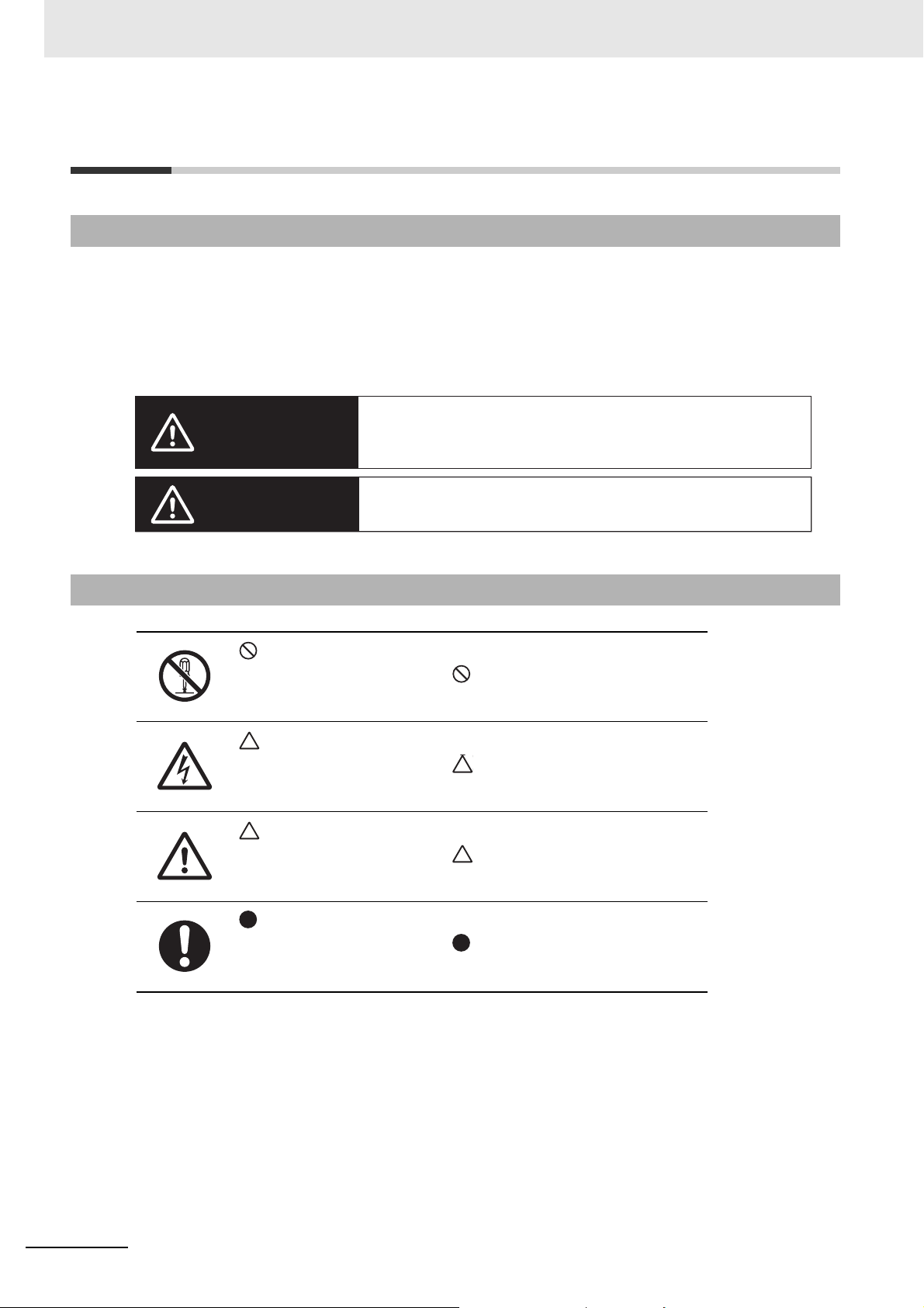
Definition of Precautionary Information
The following notation is used in this manual to provide precautions required to ensure safe usage of an
NJ Robotics Controller.
The safety precautions that are provided are extremely important to safety. Always read and heed the
information provided in all safety precautions.
The following notation is used.
WARNING
Symbols
Caution
This symbol indicates operations that you must not do.
The specific operation is shown in and explained in text.
This example indicates prohibiting disassembly.
This symbol indicates precautions (including warnings).
The specific operation is shown in and explained in text.
This example indicates a precaution for electric shock.
This symbol indicates precautions (including warnings).
The specific operation is shown in and explained in text.
This example indicates a general precaution.
This symbol indicates operations that you must do.
The specific operation is shown in and explained in text.
This example shows a general precaution for something that you must do.
14
NJ-series NJ Robotics CPU Unit User’s Manual (W539)
Page 17

Warnings
WARNING
During Power Supply
Safety Precautions
Do not touch any of the terminals or terminal blocks while the power is being supplied.
Doing so may result in electric shock.
Do not disassemble any of the Units.
Particularly the power-supplied Units contain parts with high voltages while power is supplied or immediately after power is turned OFF. Touching any of these parts may result in
electric shock. There are sharp parts inside the Units that may cause injury.
Fail-safe Measures
Provide safety measures in external circuits to ensure safety in the system if an abnormality
occurs due to malfunction of the CPU Unit, other Units, or slaves or due to other external
factors affecting operation.
Not doing so may result in serious accidents due to incorrect operation.
Emergency stop circuits, interlock circuits, limit circuits, and similar safety measures must
be provided in external control circuits.
The Controller outputs may remain ON or OFF due to deposition or burning of the output
relays or destruction of the output transistors. As a countermeasure for such problems,
external safety measures must be provided to ensure safe operation of the system.
The CPU Unit will turn OFF all outputs from Basic Output Units in the following cases.
• If an error occurs in the power supply
• If the power supply connection becomes faulty
• If a CPU watchdog timer error or CPU reset occurs
• If a major fault level Controller error occurs
• While the CPU Unit is on standby until RUN mode is entered after the power is turned
ON.
Provide external safety measures so that the system operates safely if all outputs turn OFF
when any of the above conditions occurs.
If external power supplies for slaves or other devices are overloaded or short-circuited, the
voltage will drop, outputs will turn OFF, and the system may be unable to read inputs. Provide external safety measures in controls with monitoring of external power supply voltage
as required so that the system operates safely in such a case.
Unintended outputs may occur when an error occurs in variable memory or in memory used
for CJ-series Units. As a countermeasure for such problems, external safety measures
must be provided to ensure safe operation of the system.
Provide measures in the communications system and user program to ensure safety in the
overall system even if errors or malfunctions occur in data link communications or remote
I/O communications.
NJ-series NJ Robotics CPU Unit User’s Manual (W539)
15
Page 18

Safety Precautions
If there is interference in remote I/O communications or if a major fault level error occurs,
output status will depend on the specifications of the product that is used.
Check the product's specifications and see what operation will occur when there is interference in communications or a major fault level error, and implement safety measures.
Set the slave settings correctly for all EtherCAT slaves.
The NJ-series Controller continues normal operation for a certain period of time even when
a momentary power interruption occurs. This means that the NJ-series Controller may
receive incorrect signals from external devices that are also affected by the power interruption.
Accordingly, take suitable actions, such as external fail-safe measures and interlock conditions, to monitor the power supply voltage of the external devices as required.
You must take fail-safe measures to ensure safety in the event of incorrect, missing, or
abnormal signals caused by broken signal lines, momentary power interruptions, or other
causes.
Not doing so may result in serious accidents due to incorrect operation.
Voltage and Current Inputs
Make sure that the voltages and currents that are input to the Units and slaves are within
the specified ranges.
Inputting voltages or currents that are outside of the specified ranges may cause accidents
or fire.
Downloading
Always confirm safety at the destination before you transfer a user program, configuration
data, setup data, device variables, or values in memory used for CJ-series Units from the
Sysmac Studio.
The devices or machines may perform unexpected operation regardless of the operating
mode of the CPU Unit.
16
NJ-series NJ Robotics CPU Unit User’s Manual (W539)
Page 19
Version Information
Cautions
Caution
Application
Wiring
Safety Precautions
Do not touch any Unit while power is supplied or immediately after the power supply is
turned OFF. Doing so may result in burn injury.
Be sure that all terminal screws and cable connector screws are tightened to the torques
specified in this manual or in the reference manuals. The loose screws may result in fire or
malfunction.
Online Editing
Execute online editing only after confirming that no adverse effects will be caused by deviations in the timing of I/O. If you perform online editing, the task execution time may exceed
the task period, I/O may not be refreshed with external devices, input signals may not be
read, and output timing may change.
Error Message
Precaution on Error Message That Says an Instruction May Cause Unin-
tended Operation
Instructions may results in unexpected operation and affect the system if you clear the
Detect an error when an in-out variable is passed to specific instruction argument Check
Box in the Program Check Area under the Option settings in the Sysmac Studio.
Always confirm that the conditions for use that are given in the NJ/NX-series Instructions
Reference Manual (Cat. No. W502) are met before you clear this check box.
This error message is displayed by and the above option setting is available on Sysmac Studio
version 1.02.
NJ-series NJ Robotics CPU Unit User’s Manual (W539)
17
Page 20

Safety Precautions
Simulation
Although the Sysmac Studio's simulation function simulates the operations of the Controller
and vision sensors, there are differences from the Controller and vision sensors in operation and timing. After you use the simulation function to debug the user program, always
check operation and perform adjustments on the physical Controller and vision sensors
before you use the user program to operate the controlled system. Accidents may occur if
the controlled system performs unexpected operation.
18
NJ-series NJ Robotics CPU Unit User’s Manual (W539)
Page 21

Precautions for Safe Use
Disassembly and Dropping
• Do not attempt to disassemble, repair, or modify any Units. Doing so may result in malfunction or fire.
• Do not drop any Unit or subject it to abnormal vibration or shock. Doing so may result in Unit malfunction or burning.
Mounting
The sliders on the tops and bottoms of the Power Supply Unit, CPU Unit, I/O Units, and other Units
must be completely locked (until they click into place) after connecting the adjacent Unit connectors.
Installation
Precautions for Safe Use
Always connect to a ground of 100 Ω or less when installing the Units. To avoid electric shock, be sure
to install a ground of 100 Ω or less especially when shorting the GR and LG terminals on the Power
Supply Unit.
Wiring
• Follow the instructions in the NJ-series CPU Unit Hardware User's Manual (Cat. No. W500) to correctly perform wiring.
Double-check all wiring and switch settings before turning ON the power supply.
• Use crimp terminals for wiring.
Do not connect bare stranded wires directly to terminals.
• Do not pull on the cables or bend the cables beyond their natural limit.
Do not place heavy objects on top of the cables or other wiring lines. Doing so will damage the cable.
• Mount terminal blocks and connectors only after checking the mounting location carefully.
• Make sure that the terminal blocks, expansion cables, and other items with locking devices are properly locked into place.
• Before you turn ON the power supply, be sure to remove any dustproof labels that are put on the top
of the Units when they are shipped. If the labels are not removed, heat will accumulate and malfunctions may occur.
• Before you connect a computer to the CPU Unit, disconnect the power supply plug of the computer
from the AC outlet. Also, if the computer has an FG terminal, make the connections so that the FG
terminal has the same electrical potential as the GR terminal on the Power Supply Unit.
A difference in electrical potential between the computer and Controller may cause failure or malfunction.
• If the external power supply to an Output Unit or slave has polarity, connect it with the correct polarity.
If the polarity is reversed, current may flow in the reverse direction and damage the connected
devices regardless of the operation of the Controller.
NJ-series NJ Robotics CPU Unit User’s Manual (W539)
19
Page 22

Precautions for Safe Use
Power Supply Design
• Do not exceed the rated supply capacity of the Power Supply Units used in the Controller system.
The rated supply capacities are given in the NJ-series CPU Unit Hardware User's Manual (Cat. No.
W500).
If the capacity is exceeded, operation may stop, malfunctions may occur, or data may not be backed
up normally for power interruptions.
Use only NJ-series Power Supply Units on NJ-series CPU Racks and Expansion Racks.
Operation is not possible if a CJ-series Power Supply Unit is used with an NJ-series CPU Unit or an
NJ-series Power Supply Unit is used with a CJ-series Units.
• Do not apply voltages or connect loads to the Output Units or slaves in excess of the maximum ratings.
• Surge current occurs when the power supply is turned ON. When selecting fuses or breakers for
external circuits, consider the above precaution and allow sufficient margin in shut-off performance.
Refer to the NJ-series CPU Unit Hardware User's Manual (Cat. No. W500) for surge current specifications.
• If the full dielectric strength voltage is applied or turned OFF using the switch on the tester, the generated impulse voltage may damage the Power Supply Unit. Use the adjustment on the tester to gradually increase and decrease the voltage.
• Apply the voltage between the Power Supply Unit's L1 or L2 terminal and the GR terminal when testing insulation and dielectric strength.
• Do not supply AC power from an inverter or other device with a square-wave output. Internal temperature rise may result in smoking or burning. Always input a sinusoidal wave with the frequency
that is given in the NJ-series CPU Unit Hardware User's Manual (Cat. No. W500).
• Install external breakers and take other safety measures against short-circuiting in external wiring.
When Power Is Turned ON
• It takes up to approximately 10 to 20 seconds to enter RUN mode after the power is turned ON.
During that time, outputs will be OFF or will be the values specified in the Unit or slave settings, and
external communications cannot be performed. Use the RUN output on the Power Supply Unit, for
example, to implement fail-safe circuits so that external devices do not operate incorrectly.
• Configure the external circuits so that the power supply to the control system turns ON only after the
power supply to the Controller has turned ON. If the power supply to the Controller is turned ON after
the control power supply, temporary errors may result in incorrect control system signals because the
output terminals on Output Units may momentarily turn ON when power supply is turned ON to the
Controller.
Actual Operation
Check the user program, data, and parameter settings for proper execution before you use them for
actual operation.
Turning OFF the Power Supply
• Do not turn OFF the power supply to the Controller while the BUSY indicator flashes. While the
BUSY indicator is flashing, the user program and settings in the CPU Unit are being backed up in the
built-in non-volatile memory. This data will not be backed up correctly if the power supply is turned
OFF. The next time that the Controller is started, a Controller error in the major fault level will occur
and operation will stop.
20
NJ-series NJ Robotics CPU Unit User’s Manual (W539)
Page 23

Precautions for Safe Use
• Do not turn OFF the power supply or remove the SD Memory Card while SD Memory Card access is
in progress (i.e., while the SD BUSY indicator flashes). Data may become corrupted, and the Controller will not operate correctly if it uses corrupted data. To remove an SD Memory Card from the CPU
Unit when power is supplied to the CPU Unit, press the SD Memory Card power supply switch and
wait for the SD BUSY indicator to turn OFF before you remove the Card.
• Do not disconnect the cable or turn OFF the power supply to the Controller when downloading data
or the user program from the Sysmac Studio.
• Always turn OFF the power supply to the Controller before you attempt any of the following.
a) Mounting or removing I/O Units or the CPU Unit
b) Assembling the Units
c) Setting DIP switches or rotary switches
d) Connecting cables or wiring the system
e) Connecting or disconnecting the connectors
The Power Supply Unit may continue to supply power to the rest of the Controller for a few seconds
after the power supply turns OFF. The PWR indicator is lit during this time. Confirm that the PWR
indicator is not lit before you perform any of the above.
Operation
• Confirm that the controlled system will not be adversely affected before you perform any of the following operations.
a) Changing the operating mode of the CPU Unit (including changing the setting of the Operating
Mode at Startup)
b) Changing the user program or settings
c) Changing set values or present values
d) Forced Refreshing
• Always sufficiently check the safety at the connected devices before you change the settings of an
EtherCAT slave or Special Unit.
• If two different function modules are used together, such as when you use CJ-series Basic Units and
EtherCAT slaves, take suitable measures in the user program and external controls to ensure that
safety is maintained in the controlled system if one of the function modules stops. The relevant outputs will stop if a partial fault level error occurs in one of the function modules.
• Always confirm safety at the connected equipment before you reset Controller errors with an event
level of partial fault or higher for the EtherCAT Master Function Module.
When the error is reset, all slaves that were in any state other than Operational state due to a Controller error with an event level of partial fault or higher (in which outputs are disabled) will go to Operational state and the outputs will be enabled.
Before you reset all errors, confirm that no Controller errors with an event level of partial fault have
occurred for the EtherCAT Master Function Module.
• Always confirm safety at the connected equipment before you reset Controller errors for a CJ-series
Special Unit. When the Controller error is reset, the Unit where the Controller error with an event level
of observation or higher will be restarted.
Before you reset all errors, confirm that no Controller errors with an event level of observation or
higher have occurred for the CJ-series Special Unit. Observation level events do not appear on the
Controller Error Tab Page, so it is possible that you may restart the CJ-series Special Unit without
intending to do so.
You can check the status of the _CJB_UnitErrSta[0,0] to _CJB_UnitErrSta[3,9] error status variables
on a Watch Tab Page to see if an observation level Controller error has occurred.
NJ-series NJ Robotics CPU Unit User’s Manual (W539)
21
Page 24

Precautions for Safe Use
Battery Backup
The user program and initial values for the variables are stored in non-volatile memory in the CPU Unit.
The present values of variables with the Retain attribute and the values of the Holding, DM, and EM
Areas in the memory used for CJ-series Units are backed up by a Battery.
If the Battery is not connected or the Battery is exhausted, the CPU Unit detects a Battery-backup
Memory Check Error.
If that error is detected, variables with a Retain attribute are set to their initial values and the Holding,
DM, and EM Areas in memory used for CJ-series Units are cleared to all zeros.
Perform thorough verifications and provide sufficient measures to ensure that the devices perform safe
operation for the initial values of the variables with Retain attributes and the resulting operation.
Debugging
• Forced refreshing ignores the results of user program execution and refreshes I/O with the specified
values. If forced refreshing is used for inputs for which I/O refreshing is not supported, the inputs will
first take the specified values, but they will then be overwritten by the user program. This operation
differs from the force-set/reset functionality of the CJ-series PLCs.
• You cannot upload or download information for forced refreshing with the Sysmac Studio.
After downloading data that contain the forced refreshing targets, change to RUN mode and then
execute forced refreshing from the Sysmac Studio.
Depending on the difference in the forced status, the control system may operate unexpectedly.
• Do not specify the same address for the AT specification for more than one variable.
Doing so would allow the same entity to be accessed with different variable names, which would
make the user program more difficult to understand and possibly cause programming mistakes.
General Communications
• When you use data link communications, check the error information that is given in _ErrSta (Controller Error Status) to make sure that no error has occurred in the source device. Create a user program
that uses reception data only when there is no error in the source device.
If there is an error in the source device, the data for the data link may contain incorrect values.
• Unexpected operation may result if inappropriate data link tables are set. Even if appropriate data link
tables have been set, confirm that the controlled system will not be adversely affected before you
transfer the data link tables. The data links start automatically after the data link tables are transferred.
• All CPU Bus Units are restarted when routing tables are transferred from Support Software to the
CPU Unit. Confirm that the system will not be adversely affected by restarting before you transfer the
routing tables.
• Tag data links will stop between related nodes while tag data link parameters are transferred during
Controller operation. Confirm that the system will not be adversely affected before you transfer the
tag data link parameters.
22
NJ-series NJ Robotics CPU Unit User’s Manual (W539)
Page 25

Precautions for Safe Use
EtherNet/IP Communications
• All related EtherNet/IP nodes are reset when you transfer settings for the built-in EtherNet/IP port
(including IP addresses and tag data links settings). Confirm that the system will not be adversely
affected by resetting nodes before you transfer the settings.
• If EtherNet/IP tag data links (cyclic communications) are used with a repeating hub, the communications load on the network will increase. This will increase collisions and may prevent stable communications. Do not use repeating hubs on networks where tag data links are used. Use an Ethernet
switch instead.
EtherCAT Communications
• Make sure that the communications distance, number of nodes connected, and method of connection for EtherCAT are within specifications.
Do not connect EtherCAT communications to other types of networks such as EtherNet/IP and a
standard in-house LAN. An overload may cause the network to fail or malfunction.
• Malfunctions or unexpected operation may occur for some combinations of EtherCAT revision numbers of the master and slaves. If you disable the revision check in the network settings, you must use
the Sysmac Studio to check the slave revision numbers in the master settings against the actual
slave revision numbers. Check the functional compatibility by referring to the manuals or other references of the slaves before using. You can check the actual slave revisions from the Sysmac Studio or
on slave nameplates.
• After you transfer the user program, the CPU Unit is restarted and communications with the EtherCAT slaves are cut off. During that period, the slave outputs behave according to the slave settings.
The time that communications are cut off depends on the EtherCAT network configuration. If the EtherCAT network configuration contains only OMRON EtherCAT slaves, communications are cut off for
a maximum of 45 seconds.
Before you transfer the user program, confirm that the Units will not be adversely affected.
• If the Fail-soft Operation Setting parameter is set Stop, process data communications will stop for all
slaves when an EtherCAT communications error is detected in a slave. For this reason, if Servo
Drives are connected, the Servo Drives for all axes will be turned OFF. Make sure that the Fail-soft
Operation Setting results in safe operation when a device error occurs.
• EtherCAT communications are not always established immediately after the power supply is turned
ON. Use the system-defined variables in the user program to confirm that communications are established before attempting control operations.
• If frames sent to EtherCAT slaves are lost due to noise or other causes, slave I/O data is not transmitted, and unexpected operation may occur. If noise countermeasures are required, use the _EC_In-
DataInvalid (Input Data Disable) system-defined variable as an interlock condition in the user
program.
Refer to the NJ/NX-series CPU Unit Built-in EtherCAT Port User's Manual (Cat. No. W505) for
details.
The slave outputs behave according to the slave settings. Refer to the manuals for the slaves for
details.
• When an EtherCAT slave is disconnected, communications will stop and control of the outputs will be
lost not only for the disconnected slave, but for all slaves connected after it. Confirm that the system
will not be adversely affected before you disconnect a slave.
• If you disconnect the cable from an EtherCAT slave to disconnect it from the network, any current
communications frames may be lost. If frames are lost, slave I/O data is not transmitted, and unexpected operation may occur. Perform the following processing for a slave that needs to be replaced.
a) Create the program using the _EC_InDataInvalid (Input Data Disable) system-defined variable
as an interlock condition.
b) Set the PDO communications timeout detection count to at least 2 in the EtherCAT master set-
tings pane.
NJ-series NJ Robotics CPU Unit User’s Manual (W539)
23
Page 26

Precautions for Safe Use
Refer to the NJ/NX-series CPU Unit Built-in EtherCAT Port User's Manual (Cat. No. W505) for
details.
Motion Control
• Confirm the axis number carefully before you perform an MC Test Run.
• The motor is stopped if communications are interrupted between the Sysmac Studio and the CPU
Unit during an MC Test Run. Connect the communications cable between the computer and CPU
Unit securely and confirm that the system will not be adversely affected before you perform an MC
Tes t Ru n.
• Always execute the Save Cam Table instruction if you change any of the cam data from the user program in the CPU Unit or from the Sysmac Studio. If the cam data is not saved, the previous condition
will be restored when the power is turned ON again, possibly causing unexpected machine operation.
• The positive drive prohibit input (POT), negative drive prohibit input (NOT), and home proximity input
(DEC) of the Servo Drive are used by the MC Function Module as the positive limit input, negative
limit input, and home proximity input. Make sure that the signal widths for all of these input signals
are longer than the control period of the MC Function Module. If the input signal widths are shorter
than the control period, the MC Function Module may not be able to detect the input signals, resulting
in incorrect operation.
• During setting, ensure a correct relationship between the direction of commands issued by the Controller and the motor rotation direction of the Servo Drive. Otherwise, a robot may operate unexpectedly.
• Select a correct combination of the kinematics type and workspace type for the MC_SetKinTransform
(Set Kinematics Transformation) instruction to ensure proper workspace check. Check that the workspace check function is performed as intended.
• Adjust the home of the robot before you start robot operation.
• Do not operate the robot outside the workspace while the workspace check function is disabled. If
you do so, the robot may be damaged.
• Use the MC_SyncOut (End Synchronization) instruction to stop the operation caused by the
MC_SyncLinearConveyor (Start Conveyor Synchronization) instruction.
• If you set 0 for the MaxVelocity (Velocity Error Detection Value) or MaxAcceleration (Acceleration
Error Detection Value) parameter for input variables, or if you use the default (0) of these variables,
the velocity error check or acceleration error check is not performed. Properly set the MaxVelocity
(Velocity Error Detection Value) and MaxAcceleration (Acceleration Error Detection Value) to avoid
an unexpected velocity and acceleration.
• If a robot tool (ToolID: 1 to 16) other than TCP0 is selected, the system does not perform the
pre-check of the MaxVelocity (Velocity Error Detection Value) and MaxAcceleration (Acceleration
ErrorDetection Value) parameters in the robotics instruction.
• When using Cartesian 2D kinematics, configure Plane correctly. Otherwise, a robot may operate
unexpectedly.
• When Synchronized stop with Deceleration is selected in MC_SyncOut (End Synchronization)
instruction and Deceleration target time T5 is set to long time, it is possible to reach out of the workspace during deceleration. Do not disable workspace check.
•Select Immediate stop or Immediate stop and Servo OFF when using Delta 3, Delta 3R, Delta 2, Car-
tesian 2D Gantry or Cartesian 3D Gantry robot.
• Set 0 for Maximum Deceleration which are linked mechanically, when using Delta 3, Delta 3R, Delta
2, Cartesian 2D Gantry or Cartesian 3D Gantry robot.
24
NJ-series NJ Robotics CPU Unit User’s Manual (W539)
Page 27

Precautions for Safe Use
Battery Replacement
• The Battery may leak, rupture, heat, or ignite. Never short-circuit, charge, disassemble, heat, or
incinerate the Battery or subject it to strong shock.
• Dispose of any Battery that has been dropped on the floor or otherwise subjected to excessive
shock. Batteries that have been subjected to shock may leak if they are used.
• UL standards require that batteries be replaced by experienced technicians. Make sure that an experienced engineer is in charge of Battery replacement.
• Apply power for at least five minutes before you change the Battery. Install a new Battery within five
minutes (at temperature of 25°C) after you turn OFF the power supply. If power is not supplied for at
least 5 minutes, the saved data may be lost.
Unit Replacement
• We recommend replacing the Battery with the power turned OFF to prevent the CPU Unit's sensitive
internal components from being damaged by static electricity and to prevent malfunctions. The battery can be replaced without turning OFF the power supply. To do so, always touch a grounded piece
of metal to discharge static electricity from your body before starting the procedure.
After you replace the Battery, connect the Sysmac Studio and clear the Low Battery Voltage error.
• Make sure that the required data, including the user program, configurations/setup data, variables,
and memory used for CJ-series Units, is transferred to the new CPU Unit and externally-connected
devices before you restart operation. Be sure to include the routing tables, network parameters, and
other CPU Bus Unit data, which are stored in the CPU Unit.
Disposal
• The disposal of the product and Batteries may be subject to local government regulations. Dispose of
the product and Batteries according to local ordinances as they apply.
• The following information must be displayed for all products that contain primary lithium batteries with
a perchlorate content of 6 ppb or higher when shipped to or transported through the State of California, USA.
Perchlorate Material - special handling may apply.
See www.dtsc.ca.gov/hazardouswaste/perchlorate
• The CPU Unit contains a primary lithium battery with a perchlorate content of 6 ppb or higher. Place
the above information on the individual boxes and shipping boxes when shipping finished products
that contain a CPU Unit to the State of California, USA.
NJ-series NJ Robotics CPU Unit User’s Manual (W539)
25
Page 28

Precautions for Correct Use
Precautions for Correct Use
• Do not install or store the Controller in the following locations. Operation may stop or malfunctions
may occur.
a) Locations subject to direct sunlight
b) Locations subject to temperatures or humidity outside the range specified in the specifications
c) Locations subject to condensation as the result of severe changes in temperature
d) Locations subject to corrosive or flammable gases
e) Locations subject to dust (especially iron dust) or salts
f) Locations subject to exposure to water, oil, or chemicals
g) Locations subject to shock or vibration
• Take appropriate and sufficient countermeasures when installing the Controller in the following locations.
a) Locations subject to strong, high-frequency noise
b) Locations subject to static electricity or other forms of noise
c) Locations subject to strong electromagnetic fields
d) Locations subject to possible exposure to radioactivity
e) Locations close to power supplies
• Before touching a Unit, be sure to first touch a grounded metallic object in order to discharge any
static build-up.
• Install the Controller away from sources of heat and ensure proper ventilation. Not doing so may
result in malfunction, in operation stopping, or in burning.
• An I/O bus check error will occur and the Controller will stop if an I/O Connecting Cable's connector is
disconnected from the Rack. Be sure that the connectors are secure.
• Do not allow foreign matter to enter the openings in the Unit. Doing so may result in Unit burning,
electric shock, or failure.
• Do not allow wire clippings, shavings, or other foreign material to enter any Unit. Otherwise, Unit
burning, failure, or malfunction may occur. Cover the Units or take other suitable countermeasures,
especially during wiring work.
• For EtherCAT and EtherNet/IP, use the connection methods and cables that are specified in the
NJ/NX-series CPU Unit Built-in EtherCAT Port User's Manual (Cat. No. W505) and the NJ/NX-series
CPU Unit Built-in EtherNet/IP Port User's Manual (Cat. No. W506). Otherwise, communications may
be faulty.
• Use the rated power supply voltage for the Power Supply Units. Take appropriate measures to
ensure that the specified power with the rated voltage and frequency is supplied in places where the
power supply is unstable.
• Make sure that the current capacity of the wire is sufficient. Otherwise, excessive heat may be generated. When cross-wiring terminals, the total current for all the terminals will flow in the wire. When
wiring cross-overs, make sure that the current capacity of each of the wires is not exceeded.
• Do not touch the terminals on the Power Supply Unit immediately after turning OFF the power supply.
Residual voltage may cause electrical shock.
• If you use reed switches for the input contacts for AC Input Units, use switches with a current capacity of 1 A or greater.
If the capacity of the reed switches is too low, surge current may fuse the contacts.
26
Error Processing
When you create programs for applications that use the results of instructions that read the error status,
consider how the detected error affects the system. For example, if a minor error is detected during Battery replacement, it can affect the system operation depending on the processing of the user program.
NJ-series NJ Robotics CPU Unit User’s Manual (W539)
Page 29

Precautions for Correct Use
Unit Replacement
• Refer to the CPU Bus Unit and Special I/O Unit operation manuals for details on the data required by
each Unit.
• The absolute encoder home offset is backed up with a Battery in the CPU Unit.
When you change the combination of the CPU Unit and Servomotor, e.g., when you add or replace a
Servomotor, define home again.
To restore the information without changing the CPU Unit-Servomotor combination, remove the
absolute encoder home offset from the data to restore.
Task Setup
If a Task Period Exceeded error occurs, shorten the programs to fit in the task period or increase the
setting of the task period.
Motion Control
• Use the system-defined variable in the user program to confirm that EtherCAT communications are
established before you attempt to execute motion control instructions. Motion control instructions are
not executed normally if EtherCAT communications are not established.
• Use the system-defined variables to monitor for errors in communications with the slaves that are
controlled by the motion control function module. Motion control instructions are not executed normally if an error occur in slave communications.
• Before you start an MC Test Run, make sure that the operation parameters are set correctly.
• Do not download motion control settings during an MC Test Run.
EtherCAT Communications
• Do not disconnect the EtherCAT slave cables during operation. The outputs will become unstable.
• Set the Servo Drives to stop operation if an error occurs in EtherCAT communications between the
Controller and a Servo Drive.
Battery Replacement
• Be sure to install a replacement Battery within two years of the production date shown on the Battery
label.
• Turn ON the power after replacing the Battery for a CPU Unit that has been unused for a long time.
Leaving the CPU Unit unused again without turning ON the power even once after the battery is
replaced may result in a shorter battery life.
• When you replace the Battery, use the CJ1W-BAT01 Battery Set.
SD Memory Card
• Insert the SD Memory Card all the way.
• Do not turn OFF the power supply to the Controller during SD Memory Card access. The files may be
corrupted.
If there is a corrupted file in the SD Memory Card, the file is automatically deleted by the restoration
function when the power supply is turned ON.
NJ-series NJ Robotics CPU Unit User’s Manual (W539)
27
Page 30

Regulations and Standards
Regulations and Standards
Using Product Outside Japan
If you export (or provide a non-resident with) this product or a part of this product that falls under the
category of goods (or technologies) specified by the Foreign Exchange and Foreign Trade Control Law
as those which require permission or approval for export, you must obtain permission or approval (or
service transaction permission) pursuant to the law.
Conformance to EC Directives
Applicable Directives
• EMC Directives
• Low Voltage Directive
Concepts
EMC Directives
OMRON devices that comply with EC Directives also conform to the related EMC standards so that
they can be more easily built into other devices or the overall machine. The actual products have
been checked for conformity to EMC standards.
Whether the products conform to the standards in the system used by the customer, however, must
be checked by the customer. EMC-related performance of the OMRON devices that comply with EC
Directives will vary depending on the configuration, wiring, and other conditions of the equipment or
control panel on which the OMRON devices are installed. The customer must, therefore, perform
the final check to confirm that devices and the overall machine conform to EMC standards.
*1. Applicable EMC (Electromagnetic Compatibility) standards are as follows: EN 61131-2 and EN 61000-6-2 for EMS
(Electromagnetic Susceptibility), and EN 61131-2 and EN 61000-6-4 for EMI (Electromagnetic Interference).
EN 61000-6-4 (Radiated emission) is conformed based on 10-m regulations.
Low Voltage Directive
Devices operating at voltages of 50 to 1,000 VAC and 75 to 1,500 VDC must meet the required
safety standards. The applicable directive is EN 61131-2.
Conformance to EC Directives
*1
28
The NJ/NX-series Controllers comply with EC Directives. To ensure that the machine or device in
which the NJ/NX-series Controller is used complies with EC Directives, the Controller must be
installed as follows:
• The NJ/NX-series Controller must be installed within a control panel.
• You must use reinforced insulation or double insulation for the DC power supplies connected to
DC Power Supply Units and I/O Units.
• NJ/NX-series Controllers that comply with EC Directives also conform to the Common Emission
Standard (EN 61000-6-4). Radiated emission characteristics (10-m regulations) may vary
depending on the configuration of the control panel used, other devices connected, wiring, and
other conditions.
You must therefore confirm that the overall machine or equipment complies with EC Directives.
NJ-series NJ Robotics CPU Unit User’s Manual (W539)
Page 31

Conformance to Shipbuilding Standards
This product complies with the different shipbuilding standards. Applicability to the shipbuilding
standards is based on certain usage conditions. It may not be possible to use the product in some
locations. Contact your OMRON representative before attempting to use a Controller on a ship.
Usage Conditions for NK and LR Shipbuilding Standards
• The NJ-series Controller must be installed within a control panel.
• Gaps in the door to the control panel must be completely filled or covered with gaskets or other material.
• The following noise filter must be connected to the power supply line.
Name Manufacturer Model
Noise Filter Cosel Co., Ltd. TAH-06-683
Regulations and Standards
Using Controllers in Robot Systems
The NJ501-4300/-4310/-4320/-4400/-4500 Controllers do not conform to laws and regulations relating
to the safety of industrial robot application.
When you use the NJ501-4300/-4310/-4320/-4400/-4500 Controllers in robot systems that uses industrial robots, be sure to verify the conformance to laws and regulations relating to the safety of industrial
robot application. Take measures to ensure safety as required.
Software Licenses and Copyrights
This product incorporates certain third party software. The license and copyright information associated
with this software is given in the web pages relating to the NJ501-1300/-1400/-1500 Controllers at
http://www.fa.omron.co.jp/nj_info_e/.
NJ-series NJ Robotics CPU Unit User’s Manual (W539)
29
Page 32

Versions
Versions
Hardware and software upgrades relating to the NJ-series Units and EtherCAT slaves are managed
with the number called "unit version". If any change is made in specifications of hardware or software,
the unit version number is replaced. Even when Units or EtherCAT slaves have the same model
number, they will have differences in functions and performance if they have different unit versions.
Confirming Versions
You can confirm versions in the ID information indications on the product or with the Sysmac Studio.
Confirming Versions with ID Information Indications
The version is given on the ID information indication of the products.
The following figure shows the design of the ID information for NJ Robotics NJ501-4500 CPU Units.
Robot Version
ID information indication
Unit model Unit version
NJ501 - 4500
Ver.1.
Robot Ver.1.02
PORT1 MAC ADDRESS:
PORT2 MAC ADDRESS:
Lot No. DDMYY xxxx
MAC addressesLot number and serial number
30
NJ-series NJ Robotics CPU Unit User’s Manual (W539)
Page 33

Versions
Confirming Versions with Sysmac Studio
You can use the Sysmac Studio to check the version. The procedure to check the versions differs
between a Unit and an EtherCAT slave.
Version of Units
The version of Units are given in the Production Information when the Sysmac Studio is online. You
can check the versions of the following Units: CPU Unit, CJ-series Special I/O Units, and CJ-series
CPU Bus Units. You cannot check the versions of CJ-series Basic I/O Units from the Sysmac Studio.
Use the following procedure.
1 Double-click CPU/Expansion Racks under Configurations and Setup in the Multiview
Explorer. Or, right-click CPU/Expansion Racks under Configurations and Setup and select
Edit from the menu.
The Unit Editor is displayed.
2 Right-click any open space in the Unit Editor and select Display Production Information.
The Production Information Dialog Box is displayed.
Changing Information Displayed in Production Information Dialog Box
1 Select either Show Outline or Show Detail on the lower right corner of the Production Informa-
tion Dialog Box.
The displayed information in the Production Information Dialog Box is switched between the
outline and detail.
Simple Display Detailed Display
The displayed items differ between the simple display and detailed display. The detailed display
gives the unit version, hardware version and software version. The simple display gives the unit version only.
NJ-series NJ Robotics CPU Unit User’s Manual (W539)
31
Page 34

Versions
Version of EtherCAT Slaves
The version of EtherCAT slaves are given in the Production Information Dialog Box when the Sysmac Studio is online. Use the following procedure.
1 Double-click EtherCAT under Configurations and Setup in the Multiview Explorer. Or,
right-click EtherCAT under Configurations and Setup and select Edit from the menu.
The EtherCAT Tab Page is displayed.
2 Right-click the master in the EtherCAT Tab Page and select Display Production Information.
The Production Information Dialog Box is displayed.
The unit version is shown after "Rev".
32
NJ-series NJ Robotics CPU Unit User’s Manual (W539)
Page 35

Related Manuals
Related Manuals
The following manuals are related. Use these manuals for reference.
Manual name Cat. No. Model numbers Application Description
NJ-series CPU Unit Hardware User’s Manual
NJ/NX-series CPU Unit
Software User’s Manual
NJ/NX-series Instructions
Reference Manual
NJ/NX-series CPU Unit
Motion Control User’s Manual
NJ/NX-series Motion Control Instructions Reference
Manual
NJ/NX-series CPU Unit
Built-in EtherCAT® Port
User’s Manual
W500 NJ501-
NJ301-
NJ101-
W501 NX701-
NJ501-
NJ301-
NJ101-
W502 NX701-
NJ501-
NJ301-
NJ101-
W507 NX701-
NJ501-
NJ301-
NJ101-
W508 NX701-
NJ501-
NJ301-
NJ101-
W505 NX701-
NJ501-
NJ301-
NJ101-
Learning the basic specifications of the NJ-series
CPU Units, including introductory information,
designing, installation, and
maintenance.
Mainly hardware information is provided.
Learning how to program
and set up an
NJ/NX-series CPU Unit.
Mainly software information is provided.
Learning detailed specifications on the basic
instructions of an
NJ/NX-series CPU Unit.
Learning about motion
control settings and programming concepts.
Learning about the specifications of the motion control instructions that are
provided by OMRON.
Using the built-in EtherCAT port on an
NJ/NX-series CPU Unit.
Provides an introduction to the entire
NJ-series system along with the following
information on the CPU Unit.
• Features and system configuration
•Overview
• Part names and functions
• General specifications
• Installation and wiring
• Maintenance and inspection
Use this manual together with the
NJ/NX-series CPU Unit Software User's
Manual (Cat. No. W501).
Provides the following information on a Controller built with an NJ/NX-series CPU Unit.
• CPU Unit operation
• CPU Unit features
• Initial settings
• Language specifications and programming
based on IEC 61131-3
Use this manual together with the NJ-series
CPU Unit Hardware User's Manual (Cat. No.
W500).
Describes the instructions in the instruction
set (IEC 61131-3 specifications).
When programming, use this manual
together with the NJ-series CPU Unit Hard-
ware User's Manual (Cat. No. W500) and
NJ/NX-series CPU Unit Software User's
Manual (Cat. No. W501).
Describes the settings and operation of the
CPU Unit and programming concepts for
motion control.
When programming, use this manual
together with the NJ-series CPU Unit Hard-
ware User's Manual (Cat. No. W500) and
NJ/NX-series CPU Unit Software User's
Manual (Cat. No. W501).
Describes the motion control instructions.
When programming, use this manual
together with the NJ-series CPU Unit Hard-
ware User's Manual (Cat. No. W500),
NJ/NX-series CPU Unit Software User's
Manual (Cat. No. W501), and NJ/NX-series
CPU Unit Motion Control User's Manual (Cat.
No. W507).
Provides information on the built-in EtherCAT
port.
This manual provides an introduction and
information on the configuration, features,
and setup.
Use this manual together with the NJ-series
CPU Unit Hardware User's Manual (Cat. No.
W500) and NJ/NX-series CPU Unit Software
User's Manual (Cat. No. W501).
NJ-series NJ Robotics CPU Unit User’s Manual (W539)
33
Page 36

Related Manuals
Manual name Cat. No. Model numbers Application Description
NJ/NX-series CPU Unit
Built-in EtherNet/IP™ Port
User’s Manual
NJ-series Database Connection CPU Units User’s Manual
NJ-series NJ Robotics CPU
Unit User's Manual
NJ/NX-series Troubleshooting Manual
Sysmac Studio Version 1
Operation Manual
NX-series Position Interface Units User’s Manual
W506 NX701-
NJ501-
NJ301-
NJ101-
W527 NJ501-1520
NJ501-1420
NJ501-1320
NJ501-4320
W539 NJ501-4 Using the robot control
W503 NX701-
NJ501-
NJ301-
NJ101-
W504 SYSMAC-
SE2
W524 NX-EC0
NX-ECS
NX-PG0
Using the built-in EtherNet/IP port on an
NJ/NX-series CPU Unit.
Using the database connection service with
NJ-series Controllers.
with NJ-series Controllers.
Learning about the errors
that may be detected in an
NJ/NX-series Controller.
Learning about the operating procedures and functions of the Sysmac
Studio.
Learning how to use
NX-series Position Interface Units.
Provides information on the built-in EtherNet/IP
port.
This manual provides information on the
basic setup, tag data links, and other features.
Use this manual together with the NJ-series
CPU Unit Hardware User's Manual (Cat. No.
W500) and NJ/NX-series CPU Unit Software
User's Manual (Cat. No. W501).
Describes the database connection service.
Describes the robot control.
Use this manual together with the
NJ/NX-series CPU Unit Motion Control
User’s Manual (Cat. No. W507) and the
NJ/NX-series Motion Control Instructions
Reference Manual (Cat. No. W508).
Describes concepts on managing errors that
may be detected in an NJ/NX-series Controller and information on individual errors.
Use this manual together with the NJ-series
CPU Unit Hardware User's Manual (Cat. No.
W500) and NJ/NX-series CPU Unit Software
User's Manual (Cat. No. W501).
Describes the operating procedures of the
Sysmac Studio.
Describes the hardware, setup, and functions for the NX-series Incremental Encoder
Input Units, SSI Input Units, and Pulse Output Unit.
34
NJ-series NJ Robotics CPU Unit User’s Manual (W539)
Page 37

Terminology
Terminology
Term Description
NJ501-1 The model number NJ501-1300, NJ501-1400 or NJ501-1500.
NJ-series NJ Robotics CPU Unit The model number NJ501-4300, NJ501-4310, NJ501-4320, NJ501-4400 or
NJ501-4500. These models may also be written as "NJ501-4".
Sysmac Studio Robot Options The optional functions of the Sysmac Studio provided to use NJ501-4 robot
functions.
Robot The mechanism (e.g. Delta and Scalar) that consists of multiple links and axes.
Delta The robots that use parallel link mechanism.
This Controller can control 2-parallel-link type robots and 3-parallel-link type robots.
Some robots have a rotational axis at their wrist.
Delta3 In this manual, a Delta robot with three parallel links is called Delta3.
Delta3R In this manual, a Delta robot with three parallel links and a rotational wrist axis is
called Delta3R.
Delta2 In this manual, a Delta robot with two parallel links is called Delta2.
Cartesian Robot A robot arm with prismatic joints, which allows movement along one or more of the
three axes in the X, Y, Z coordinate system.
Gantry Robot A Cartesian robot which moves along with the gantry system as X-axis. The gantry
system is composed with two linear axes which positioned in parallel.
H-Bot A robot composed of two rotary drives which are connected by a single H-shaped
circumferential timing belt around two parallel linear rails.
T-Bot A variation of H-Bot with a T-shape and one linear rail instead of two.
Kinematics In this manual, the kinematics refers to a set of expressions required for the follow-
ing two transforms.
• Transform from the axis coordinate systems (ACS) of robot links and axes to the
robot-specific Cartesian coordinate system (MCS).
• Transform from the robot-specific Cartesian coordinate system (MCS) to the axis
coordinate systems (ACS) of robot links and axes.
Inverse Kinematics Transform from a position in the robot-specific Cartesian coordinate system (MCS)
to a position in axis coordinate systems (ACS) of robot links and axes.
Direct Kinematics Transform from a position in axis coordinate systems (ACS) of robot links and axes
to a position in the robot-specific Cartesian coordinate system (MCS).
Axis Coordinate System A coordinate system for rotation or linear motion specified for each axis of the
robot.
The abbreviation is ACS.
Machine Coordinate System
User Coordinate System A Cartesian coordinate system defined by the user.
Tool Coordinate System A Cartesian coordinate system which has TCP at its origin.
TCS0
(Tool Coordinate System 0)
TCSi
(Tool Coordinate System i)
TCP (Tool Center Point)
TCP0 (Tool Center Point 0) This is the default TCP.
A Cartesian coordinate system which is specific to the machine (robot).
The abbreviation is MCS.
The abbreviation is UCS.
The abbreviation is TCS.
The default TCS. Its origin is TCP0.
A TCS currently selected by the robot. The symbol i represents ToolID of the TCS.
The i takes on values from 1 to 16.
The tip of the machine (robot) that performs tasks.
Specify the position of TCP when you perform positioning for the Cartesian coordinate system.
NJ-series NJ Robotics CPU Unit User’s Manual (W539)
35
Page 38

Terminology
Term Description
TCPi (Tool Center Point i) The TCP of a certain tool. The symbol i represents ToolID of the TCP. The i takes
on values from 1 to 16.
Robot TCP
(Robot Tool Center Point)
Active TCP
(Active Tool Center Point)
Fixed Frame
Moving Frame In a Delta robot, it refers to a frame driven by the axes motors.
Robot Tool A mechanical part attached to the robot flange. This part performs tasks for work-
Vision & Robot Integrated Simulation A simulation of the pick-and-place application where this Controller is used in com-
Robot Additional Option The optional functions required to perform a Vision & Robot integrated simulation.
The default TCP of the robot. This is the same thing as TCP0.
A TCP which is currently selected by the robot. If you select ToolID i for a TCP, the
selected TCP becomes the active TCP. The i takes on values from 1 to 16.
In a Delta robot, it refers to a frame to which the axes motors are attached.
pieces.
bination with one or more vision sensors and Delta robots.
The option becomes available when you enter a license number in the Sysmac Studio version 1.14 or higher.
36
NJ-series NJ Robotics CPU Unit User’s Manual (W539)
Page 39

Revision History
W539-E1-04
Cat. No.
Revision code
A manual revision code appears as a suffix to the catalog number on the front and back covers of the
manual.
Revision code Date Revised content
01 April 2015 Original production
02 October 2015 Added information on Vision & Robot integrated simulation.
03 April 2016 Made changes accompanying release of robot version 1.03 of the CPU Unit.
04 June 2016 Updated the EtherNet/IP logo.
Revision History
NJ-series NJ Robotics CPU Unit User’s Manual (W539)
37
Page 40

Revision History
38
NJ-series NJ Robotics CPU Unit User’s Manual (W539)
Page 41

Overview of NJ Robotics CPU Unit
This section describes the features, system configuration, operating procedure, specifications and control configuration of an NJ-series NJ Robotics CPU Unit.
1-1 Features and System Configuration of Unit . . . . . . . . . . . . . . . . . . . . . . . . 1-2
1-1-1 Features of NJ Robotics CPU Unit . . . . . . . . . . . . . . . . . . . . . . . . . . . . . . . . . 1-2
1-1-2 Introduction to the System Configurations . . . . . . . . . . . . . . . . . . . . . . . . . . . 1-4
1-2 Operation Procedure of Unit . . . . . . . . . . . . . . . . . . . . . . . . . . . . . . . . . . . . . 1-7
1-3 Specifications of Unit . . . . . . . . . . . . . . . . . . . . . . . . . . . . . . . . . . . . . . . . . . 1-8
1-3-1 Performance Specifications . . . . . . . . . . . . . . . . . . . . . . . . . . . . . . . . . . . . . . 1-8
1-3-2 Function Specifications . . . . . . . . . . . . . . . . . . . . . . . . . . . . . . . . . . . . . . . . . . 1-8
1-4 Robot Control Configuration . . . . . . . . . . . . . . . . . . . . . . . . . . . . . . . . . . . 1-10
1
NJ-series NJ Robotics CPU Unit User’s Manual (W539)
1 - 1
Page 42

1 Overview of NJ Robotics CPU Unit
Automation Software
Sysmac Studio
NJ-series Controller
Multitasking, synchronized control
IEC programming
EtherCAT control network
Safety devices I/O controls Servo Drives
and Inverters
Machine vision
Sequence control Motion control
1-1 Features and System Configuration
of Unit
The NJ-series Machine Automation Controllers are next-generation machine automation controllers
that provide the functionality and high-speed performance that are required for machine control. They
provide the safety, reliability, and maintainability that are required of industrial controllers.
The NJ-series Controllers provide the functionality of previous OMRON PLCs, and they also provide
the functionality that is required for motion control. Synchronized control of I/O devices on high-speed
EtherCAT can be applied to safety devices, vision systems, motion equipment, discrete I/O, and more.
OMRON offers the new Sysmac Series of control devices designed with unified communications specifications and user interface specifications. The NJ-series Machine Automation Controllers are part of
the Sysmac Series. You can use them together with EtherCAT slaves, other Sysmac products, and the
Sysmac Studio Automation Software to achieve optimum functionality and ease of operation.
With a system that is created from Sysmac products, you can connect components and operate the
system through unified concepts and usability.
1-1-1 Features of NJ Robotics CPU Unit
1 - 2
The NJ Robotics CPU Unit has the following features.
Integrated Sequence Control and Motion Control
Multitasking
An NJ-series CPU Unit can perform both sequence control and motion control. You can simultaneously achieve both sequence control and multi-axes synchronized control. Sequence control,
motion control, and I/O refreshing are all executed in the same control period.
The same control period is also used for the process data communications cycle for EtherCAT. This
enables precise sequence and motion control in a fixed period with very little deviation.
You can assign I/O refreshing and programs to tasks and then specify execution conditions and execution order for them to flexibly combine controls that suit the application.
NJ-series NJ Robotics CPU Unit User’s Manual (W539)
Page 43

1 Overview of NJ Robotics CPU Unit
1-1 Features and System Con-
Robot Instructions Supported
Robot operation, single-axis operation and synchronized operation can all be achieved with the
Motion Control Function Module (hereinafter called "MC Function Module").
Programming Languages Based on the IEC 61131-3 International Standard
The NJ-series Controllers support language specifications that are based on IEC 61131-3. To these,
OMRON has added our own improvements. Motion control instructions that are based on PLCopen
standards and an instruction set (POUs) that follows IEC rules are provided.
A Wealth of Security Features
The many security features of the NJ-series Controllers include operation authority settings and
restriction of program execution with IDs.
Complete Controller Monitoring
The CPU Unit monitors events in all parts of the Controller, including mounted Units and EtherCAT
slaves.
Troubleshooting information for errors is displayed on the Sysmac Studio or on an HMI. Events are
also recorded in logs.
Sysmac Studio Automation Software
The Sysmac Studio provides an integrated development environment that covers not only the Controller, but also covers peripheral devices and devices on EtherCAT. You can use consistent procedures for all devices regardless of the differences in the devices. The Sysmac Studio supports all
phases of Controller application, from designing through debugging, simulations, commissioning,
and changes during operation.
figuration of Unit
1
1-1-1 Features of NJ Robotics CPU Unit
A Wealth of Simulation Features
The many simulation features include execution, debugging, and task execution time estimates on a
virtual controller.
NJ-series NJ Robotics CPU Unit User’s Manual (W539)
1 - 3
Page 44

1 Overview of NJ Robotics CPU Unit
Sysmac Studio
USB
or
EtherNet/IP
LAN
EtherCAT
Support Software
EtherCAT Network
Configuration
Servo Drives
and Inverters
Vision
Sensors
Slave Terminal
Counters and Sensors
NJ-series
Power
Supply Unit
Peripheral USB port
NJ Robotics
CPU Unit
CPU rack
Built-in EtherCAT port
Built-in EtherNet/IP port
1-1-2 Introduction to the System Configurations
The NJ Robotics CPU Unit supports the following system configurations.
Basic System Configuration
The NJ-series basic configurations include the EtherCAT network configuration and the Support Software.
EtherCAT Network Configuration
You can use the built-in EtherCAT port to connect to EtherCAT Slave Terminals, to general-purpose
slaves for analog and digital I/O, and to Servo Drives and encoder input slaves. An EtherCAT network configuration enables precise sequence and motion control in a fixed cycle with very little deviation.
Support Software
The Support Software is connected to the peripheral USB port on the CPU Unit with a commercially
available USB cable. You can also connect it through an Ethernet cable that is connected to the
built-in EtherNet/IP port.
Refer to the NJ/NX-series CPU Unit Software User's Manual (Cat. No. W501) for details on the connection with the Support Software.
1 - 4
NJ-series NJ Robotics CPU Unit User’s Manual (W539)
Page 45

1 Overview of NJ Robotics CPU Unit
Sensor
Encoder
Box Box
Motor
Motor
Box Box
Vision sensor
Encoder
Puts cylinders
Vision sensor
EncoderEncoderEncoder
Puts cubes
Box
Box
Motor
Motor
Encoder
1-1 Features and System Con-
Robot System Configuration
The following figures show the robot system configurations.
Packing 1
The sensor detects workpieces and the robots put them into boxes.
Packing 2
The vision sensor detects workpieces conveyed randomly, and the robots put them into boxes.
figuration of Unit
1
1-1-2 Introduction to the System Configurations
Packing 3
The vision sensor detects different shapes of workpieces and the robots put them into boxes accordingly.
NJ-series NJ Robotics CPU Unit User’s Manual (W539)
1 - 5
Page 46

1 Overview of NJ Robotics CPU Unit
Motor
Motor
Vision sensor
Encoder
Encoder
Alignment
The robots align workpieces conveyed randomly, and line them up on another conveyor.
1 - 6
NJ-series NJ Robotics CPU Unit User’s Manual (W539)
Page 47

1 Overview of NJ Robotics CPU Unit
START
END
Select absolute encoders and motors with
brakes.
*1
Install the motors so that they can meet the
requirements of relationship between the machine
coordinate system and axis coordinate systems
.
*1
Match the positive direction of the axis
coordinate system with that of the motor.
*1
Create a project.
Create the EtherCAT Network Configuration.
Add three axes for the robot.
*1
Select an axes group used for the robot and
assign axes to the logical axes of the group.
*1
Set the axis parameters.
Set the Controller Setup.
Open the MC Test Run Pane.
Monitor input/output signals to check the wiring.
Perform homing for the robot.
*1
Create control programs.
Perform debugging.
Operate the Controller and the machine.
Perform periodic maintenance.
Jog the axes to check that the axes operate
properly and operation directions are correct
in both positive and negative directions.
*1
Transfer the project to the Controller.
Selection
Installation and
wiring check
Setup
Transferring
Checking wiring
Checking operation
Homing
Programming
Debugging
Operation
Maintenance
1-2 Operation Procedure of Unit
This section provides the procedure to operate a Delta3 robot.
1-2 Operation Procedure of Unit
1
NJ-series NJ Robotics CPU Unit User’s Manual (W539)
*1. This procedure is different from that for NJ501-1 Units. Refer to the NJ/NX-series CPU Unit Motion
Control User's Manual (Cat. No. W507) for information on other procedures.
1 - 7
Page 48

1 Overview of NJ Robotics CPU Unit
1-3 Specifications of Unit
This section gives the performance specifications and function specifications of an NJ Robotics CPU
Unit.
1-3-1 Performance Specifications
The following robot functions are added to the MC Function Module for NJ Robotics CPU Units with
model numbers NJ501-1.
Item Overview
Coordinate System The two types of systems, the machine coordinate system (MCS) and user coordi-
nate system (UCS), are provided for robot operation.
Robot Parameter Settings Sets the robot parameters including the kinematics type and link length.
Workspace Check Checks whether the robot operates within the range of motion (workspace).
User Coordinate System You can set the user coordinate systems for each robot.
Robot Tool You can set multiple robot tools for each robot.
Monitoring Reads the current position and current velocity of the robot.
Time-specified Absolute
Positioning
Conveyor Synchronization Makes the robot to track the workpiece on the conveyor.
Inverse Kinematics Transforms the coordinates (X, Y, Z, Rx, Ry, Rz) of the robot to the axis coordi-
Robot Jogging Jogs the robot.
Transition You can select the method to make a smooth transition trajectory between robot
Robot Velocity and Acceleration check
Synchronized Offset functionality
Moves the robot to a set position in a set time period.
nates.
operation instructions.
Checks robot maximum velocity and acceleration (pre-check and online check).
You can set offsets during conveyor synchronization.
1-3-2 Function Specifications
1 - 8
The following table shows the function specifications of an NJ Robotics CPU Unit.
Item
Applicable robots Delta3, Delta3R, Delta2, Cartesian 3D, Cartesian 3D Gantry, Cartesian 2D,
Controllable Servo Drives
Controllable encoder input terminals
Control method Control commands using EtherCAT communications
Control modes Position control (Cyclic Synchronous Position Control Mode)
NJ501-4500 NJ501-4400 NJ501-4300 NJ501-4320 NJ501-4310
Cartesian 2D Gantry and H-Bot
OMRON G5-series Servo Drives with built-in EtherCAT communications
OMRON GX-series EtherCAT Remote I/O Terminals
GX-EC0211/-EC0241
OMRON NX-series Incremental Encoder Units
NX-EC0122/-EC0222/-EC0142
OMRON NX-series SSI Input Units
NX-ECS112/-ECS212
Velocity control (Cyclic Synchronous Velocity Control Mode)
Torque control (Cyclic Synchronous Torque Control Mode)
Specification
*7
*1
*2
*3
*3
NJ-series NJ Robotics CPU Unit User’s Manual (W539)
Page 49

1 Overview of NJ Robotics CPU Unit
1-3 Specifications of Unit
Specification
Number of
controlled
axes
Item
Maximum number
NJ501-4500 NJ501-4400 NJ501-4300 NJ501-4320 NJ501-4310
64 axes 32 axes 16 axes
of controlled axes
Single-axis control 64 axes max. 32 axes max. 16 axes max.
Linear interpola-
tion control
*4
Circular interpola-
tion control
*4
4 axes max. per axes group
2 axes per axes group
Number of axes groups 32 groups max.
Unit con-
version
Unit of display pulse, mm, nm, degree and inch
Electronic gear
Pulse per motor rotation/travel distance per motor rotation
ratio
Positions that can be managed Command positions and actual positions
Position command values
Velocity command values
Acceleration command values
Negative or positive long reals (LREAL) or 0 (unit: command units
Negative or positive long reals (LREAL) or 0 (unit: command units/s)
Positive long reals (LREAL) or 0 (unit: command units/s
2
)
*5
)
*6
and deceleration command values
Jerk command values
Positive long reals (LREAL) or 0 (unit: command units/s
2
)
Override factors 0.00% or 0.01% to 500.00%
Axis type Servo axes, Virtual servo axes, Encoder axes, and Virtual encoder axes
Motion control period The same control period as that is used for the process data communica-
tions cycle for EtherCAT.
Use the robot functions with the period of 1 ms, 2 ms or 4 ms.
Cams Number of cam
data
Number of cam
65,535 points max. per cam table
1,048,560 points max. for all cam tables
640 tables max.
tables
Cam profile curve Created with the Cam Editor.
Overwriting cam
Can be overwritten from the user program.
data
Coordinate System
Axis coordinate
system (ACS)
Machine coordi-
1 system per axis
1 system per group
nate system (MCS)
User coordinate
16 systems per group
system (UCS)
Tool coordinate
17 systems per group (default + defined robot tools)
system (TCS)
Robot tool 16 tools group
Maximum number of robots 8 8 8 1
*1. Unit version 2.1 or later is recommended.
*2. Unit version 1.1 or later is recommended.
*3. Attach the unit to a NX-ECC201 EtherCAT Coupler Unit.
*4. You cannot use this function for robot control.
*5. Positions can be set within a 40-bit signed integer range when converted to pulses.
*6. The maximum velocity command value is 400 Mpps (in pulses) when you use OMRON G5-series Servo
Drives.
*7. Cartesian 3D, Cartesian 3D Gantry, Cartesian 2D, Cartesian 2D Gantry and H-Bot are applicable only in
Robot Version 1.03 or later.
1
1-3-2 Function Specifications
NJ-series NJ Robotics CPU Unit User’s Manual (W539)
1 - 9
Page 50

1 Overview of NJ Robotics CPU Unit
M
E
Motion Control
Instructions
Motion Control
Instructions
(Robot
Instructions)
Command
interpretation
Data processing
Data processing
for robot
Communications
processing
EtherCAT
communications
Position control
Velocity control
Torque control
NJ501-4300/-4310/-4320/-4400/-4500
User program
EtherCAT Master
Function Module
MC Function
Module
Servo Drive
A feedback system is not configured. A feedback system is configured.
Communications
processing
Command
interpretation
Status control
1-4 Robot Control Configuration
A control system built with Servo Drives generally controls motor operation with a semi-closed loop.
The semi-closed loop uses an encoder attached to the motor to detect the amount of rotation that has
been performed by the motor in response to the command value. This is provided as feedback of the
machine's travel distance. The following error between the command value and actual motor rotation is
calculated and control is performed to bring the following error to zero.
In a machine configuration that uses the MC Function Module, no feedback information is provided for
the commands from the user program in the CPU Unit. A feedback system is built into the Servo Drive.
The NJ Robotics CPU Units are the NJ501-1 Units to which the instructions and data processing
for robot operation were added, as shown in the following figure.
With these instructions and data processing, the NJ Robotics CPU Unit can perform robot control in the
same way as other NJ501-1 Units' motion control, using function blocks based on IEC 61131-3.
For details on the configuration and principles of the motion control system, refer to the NJ/NX-series
CPU Unit Motion Control User's Manual (Cat. No. W507).
1 - 10
NJ-series NJ Robotics CPU Unit User’s Manual (W539)
Page 51

Features of NJ Robotics CPU Unit
This section describes the types of robots you can control, their coordinate systems
and functions.
2-1 Controllable Robot Types . . . . . . . . . . . . . . . . . . . . . . . . . . . . . . . . . . . . . . . 2-2
2-2 Coordinate System . . . . . . . . . . . . . . . . . . . . . . . . . . . . . . . . . . . . . . . . . . . . 2-5
2-2-1 Overview of Coordinate Systems . . . . . . . . . . . . . . . . . . . . . . . . . . . . . . . . . . 2-5
2-2-2 Coordinate Systems . . . . . . . . . . . . . . . . . . . . . . . . . . . . . . . . . . . . . . . . . . . 2-14
2-3 Robot Functions . . . . . . . . . . . . . . . . . . . . . . . . . . . . . . . . . . . . . . . . . . . . . . 2-15
2-3-1 Kinematics Setting . . . . . . . . . . . . . . . . . . . . . . . . . . . . . . . . . . . . . . . . . . . . 2-15
2-3-2 Workspace Check . . . . . . . . . . . . . . . . . . . . . . . . . . . . . . . . . . . . . . . . . . . . . 2-23
2-3-3 User Coordinate System (UCS) . . . . . . . . . . . . . . . . . . . . . . . . . . . . . . . . . . 2-29
2-3-4 Monitoring . . . . . . . . . . . . . . . . . . . . . . . . . . . . . . . . . . . . . . . . . . . . . . . . . . . 2-30
2-3-5 Time-specified Absolute Positioning . . . . . . . . . . . . . . . . . . . . . . . . . . . . . . . 2-30
2-3-6 Conveyor Synchronization . . . . . . . . . . . . . . . . . . . . . . . . . . . . . . . . . . . . . . 2-31
2-3-7 Inverse Kinematics . . . . . . . . . . . . . . . . . . . . . . . . . . . . . . . . . . . . . . . . . . . . 2-32
2-3-8 Robot Tool . . . . . . . . . . . . . . . . . . . . . . . . . . . . . . . . . . . . . . . . . . . . . . . . . . 2-32
2-3-9 Robot Jogging . . . . . . . . . . . . . . . . . . . . . . . . . . . . . . . . . . . . . . . . . . . . . . . 2-34
2-3-10 Checking Maximum Interpolation Velocity and Maximum Interpolation
Acceleration/Deceleration . . . . . . . . . . . . . . . . . . . . . . . . . . . . . . . . . . . . . . . 2-35
2-3-11 Multi-execution of Instructions with Buffered Mode . . . . . . . . . . . . . . . . . . . 2-37
2-3-12 Multi-execution of Instructions with Blending Mode . . . . . . . . . . . . . . . . . . . 2-37
2-3-13 Trajectory Types for Time-specified Motion . . . . . . . . . . . . . . . . . . . . . . . . . 2-38
2
NJ-series NJ Robotics CPU Unit User’s Manual (W539)
2 - 1
Page 52

2 Features of NJ Robotics CPU Unit
2-1 Controllable Robot Types
The robot types connectable to the NJ Robotics CPU Unit are Delta3, Delta3R, Delta2, Cartesian 3D,
Cartesian 3D Gantry, Cartesian 2D, Cartesian 2D Gantry and H-Bot.
The following figure is an example of Delta3.
The following figure is an example of Delta2.
2 - 2
NJ-series NJ Robotics CPU Unit User’s Manual (W539)
Page 53

2 Features of NJ Robotics CPU Unit
The following figure is an example of Cartesian 2D.
2-1 Controllable Robot Types
2
The following figure is an example of Cartesian 3D Gantry.
NJ-series NJ Robotics CPU Unit User’s Manual (W539)
2 - 3
Page 54

2 Features of NJ Robotics CPU Unit
The following figure is an example of H-bot.
2 - 4
NJ-series NJ Robotics CPU Unit User’s Manual (W539)
Page 55

2-2 Coordinate System
Zm
Ym
A2
TCP
Xm
Machine coordinate
system (MCS)
Axis coordinate
system (ACS)
Moving frame
User coordinate system (UCS)
A1
A0
Xu
Yu
Zu
Fixed frame
This section describes the coordinate systems used by an NJ Robotics CPU Unit.
2-2-1 Overview of Coordinate Systems
This section describes the types of coordinate systems, the directions of axis coordinate systems
(ACS), and the positional relationship between the axis coordinate systems (ACS) and the machine
coordinate system (MCS).
2 Features of NJ Robotics CPU Unit
2-2 Coordinate System
2
Types of Coordinate Systems
2-2-1 Overview of Coordinate Systems
An NJ Robotics CPU Unit uses the following coordinate systems to control the robots.
Coordinate System Description
Axis coordinate system (ACS)
Machine coordinate
system (MCS)
User coordinate system (UCS)
Tool coordinate system (TCS)
The coordinate systems shown with A0, A1
and A2 in the following figure
The coordinate system shown with Xm, Ym
and Zm in the following figure
The coordinate system shown with Xu, Yu
and Zu in the following figure
The coordinate system shown with Xt, Yt
and Zt in the following figure
Reference
P. 2-14
P. 2-14
P. 2-14
P. 2-14
Coordinate Systems for Delta3
NJ-series NJ Robotics CPU Unit User’s Manual (W539)
2 - 5
Page 56

2 Features of NJ Robotics CPU Unit
A
Xt
YtYt
ZtZtYtZt
Xt
Zt
Yt
Tool coordinate system (TCSn)
Tool coordinate
system (TCS0)
Coordinate Systems for Delta3R
Ym
xis coordinate
system (ACS)
Moving frame
Zu
User coordinate system (UCS)
A2
Yu
Xu
Zm
A3
Robot TCP
Machine coordinate
system (MCS)
A1
Xm
A0
Fixed frame
2 - 6
NJ-series NJ Robotics CPU Unit User’s Manual (W539)
Page 57

Coordinate Systems for Delta2
Xm
A0A1
Zu
Xu
Zm
Machine coordinate
system (MCS)
Moving frame
Fixed frame
User coordinate system (UCS)
Machine coordinate
system (MCS)
Xm
Ym
Zm
User coordinate
system (UCS)
XuYu
Zu
TCP
A0
A1
A2
The figure shows Delta2 viewed from Ym direction.
2 Features of NJ Robotics CPU Unit
2-2 Coordinate System
2
2-2-1 Overview of Coordinate Systems
Coordinate Systems for Cartesian 3D
NJ-series NJ Robotics CPU Unit User’s Manual (W539)
2 - 7
Page 58

2 Features of NJ Robotics CPU Unit
Machine coordinate
system (MCS)
Xm
Ym
Zm
User coordinate
system (UCS)
XuYu
Zu
TCP
A0
A2
A1
A3
Machine coordinate
system (MCS)
Xm
Ym
Zm
User coordinate
system (UCS)
XuYu
Zu
TCP
A0
A1
Coordinate Systems for Cartesian 3D Gantry
Coordinate Systems for Cartesian 2D
The Cartesian 2D kinematics can be arranged in the three coordinate planes:
• Cartesian XY kinematics
• Cartesian XZ kinematics
• Cartesian YZ kinematics
The figure is an example of Catersian XY kinematics.
2 - 8
NJ-series NJ Robotics CPU Unit User’s Manual (W539)
Page 59

2 Features of NJ Robotics CPU Unit
Machine coordinate
system (MCS)
Xm
Ym
Zm
User coordinate
system (UCS)
XuYu
Zu
TCP
A2
A0
A1
Xm
Ym
Machine coordinate
system (MCS)
Xu
Yu
User coordinate
system (UCS)
A0
A1
TCP
Coordinate Systems for Cartesian 2D Gantry
2-2 Coordinate System
2
2-2-1 Overview of Coordinate Systems
The Cartesian 2D Gantry kinematics can be arranged only in XY coordinate plane.
Coordinate Systems for H-Bot
The H-Bot kinematics has 4 sub types.
Direction of TCP movement depends on direction of the axes A0 and A1, and depends on H-Bot
type.
• H-Bot type 1
A0 movement
direction
Positive Positive Positive No movement
Positive Negative No movement Positive
Negative Positive No movement Negative
Negative Negative Negative No movement
A1 movement
direction
X movement
direction
Y movement
direction
NJ-series NJ Robotics CPU Unit User’s Manual (W539)
2 - 9
Page 60

2 Features of NJ Robotics CPU Unit
Xm
Ym
Machine coordinate
system (MCS)
A0
A1
TCP
Xm
Ym
Machine coordinate
system (MCS)
Xu
Yu
User coordinate
system (UCS)
A0
A1
TCP
H-Bot1 kinematics can be used also with CoreXY robot.
• H-Bot type 2
A0
Machine coordinate
system (MCS)
Ym
Xm
TCP
Yu
User coordinate
Xu
system (UCS)
A1
A0 movement
direction
A1 movement
direction
X movement
direction
Y movement
direction
Positive Positive Negative No movement
Positive Negative No movement Positive
Negative Positive No movement Negative
Negative Negative Positive No movement
• T-Bot type 1
2 - 10
NJ-series NJ Robotics CPU Unit User’s Manual (W539)
Page 61

2 Features of NJ Robotics CPU Unit
Xm
Ym
Machine coordinate
system (MCS)
Xu
Yu
User coordinate
system (UCS)
A0
A1
TCP
A0 movement
direction
Positive Positive Negative No movement
Positive Negative No movement Negative
Negative Positive No movement Positive
Negative Negative Positive No movement
A1 movement
direction
X movement
direction
Y movement
direction
2-2 Coordinate System
• T-Bot type 2
2
2-2-1 Overview of Coordinate Systems
A0 movement
direction
Positive Positive Positive No movement
Positive Negative No movement Negative
Negative Positive No movement Positive
Negative Negative Negative No movement
A1 movement
direction
X movement
direction
Y movement
direction
Directions of Axis Coordinate System (ACS)
Directions of ACS for Delta Robots
This coordinate system is applied to three axes, A0 to A2, of Delta3 and Delta3R, and two axes, A0
and A1, of Delta2.
"0 Degree" refers to an axis position at which the fixed frame and link 1 form a straight line. The
direction below the 0 degree line is called Positive Direction, and the direction above the 0 degree
line is called Negative Direction. The settings of axes (Servo Drives) must conform with this axis
coordinate system (ACS).
You must wire so that an axis operates in a downward direction if a positive command velocity is
given, and the axis operates in an upward direction if a negative command velocity is given.
NJ-series NJ Robotics CPU Unit User’s Manual (W539)
2 - 11
Page 62

2 Features of NJ Robotics CPU Unit
Fixed frame
Link 1
Link 2
Negative direction
0 [degree]
Positive direction
Xm
Ym
Zm
A0
A1
A2
A0 positive
A1 positive
A2 positive
Machine coordinate
system (MCS)
Wire a Servomotor so that the motor rotates in the directions shown in the following figure.
Directions of ACS for Cartesian Robots and Gantry Robots
Kinematics type
Axes
A0 XXXXYX
A1 YXYZZX
A2 Z Y Not used Y
A3 Not used Z Not used Not used
Cartesian 3DCartesian
3D Gantry
Plane XY Plane XZ Plane YZ
Cartesian 2D
Cartesian
2D Gantry
Then, positive direction of each axis must follow the positive direction of the corresponding coordinate.
The following figure is an example of Cartesian 3D.
In these robots, each axis is corresponding to one of coordinate X, Y or Z. See the following table.
2 - 12
NJ-series NJ Robotics CPU Unit User’s Manual (W539)
Page 63

2 Features of NJ Robotics CPU Unit
Precautions for Safe Use
Xm
Ym
A0
A1
A0 positive
A1 positive
Machine coordinate
system (MCS)
Xm
Ym
A1
A2
A0
A3(-)
A3(+)
Directions of ACS for H-Bots and T-Bots
In these robots, positive direction of each axis is counter-clockwise in plane XY.
The following figure is an example of H-Bot type 1.
2-2 Coordinate System
2
2-2-1 Overview of Coordinate Systems
Positional Relationship between Axis Coordinate System (ACS) and
Machine Coordinate System (MCS)
The following figure shows the directions of the axis coordinate system (ACS) of each axis (A0 to A2
and A3) and the directions of the machine coordinate system (MCS).
The figure shows the fixed frame of a Delta3 robot viewed from Zm direction.
NJ-series NJ Robotics CPU Unit User’s Manual (W539)
Set a correct relationship between the direction of commands given by the Controller and the
motor rotation direction of the Servo Drive.
Otherwise, the robot may operate unexpectedly.
2 - 13
Page 64

2 Features of NJ Robotics CPU Unit
Precautions for Correct Use
The positional relationship between axes, and the directions of their coordinate systems are
fixed and cannot be changed.
2-2-2 Coordinate Systems
This section describes the axis coordinate system (ACS), the machine coordinate system (MCS), the
user coordinate system (UCS), and the tool coordinate system (TCS).
Axis Coordinate System (ACS)
The axis coordinate system (ACS) is a rotation or linear motion coordinate system specified for each
axis.
This system is also called the Joint Coordinate System or the Link Coordinate System.
Each axis has one coordinate system.
Machine Coordinate System (MCS)
The machine coordinate system (MCS) is a Cartesian coordinate system specified for each robot.
Use the position of the robot TCP viewed from the origin of the machine coordinate system to set the
target position for robot operation.
Each robot (one axes group) has one machine coordinate system.
User Coordinate System (UCS)
The user coordinate system is a Cartesian coordinate system defined by the user.
Use the rotation and the position relative to the origin of the machine coordinate system to set the origin
position (Tx, Ty, Tz, Rx, Ry, Rz) of the user coordinate systems. The rotation is also called Pose.
You can set up to 16 user coordinate systems for each robot.
Tool Coordinate System (TCS)
The tool coordinate system is a Cartesian coordinate system set by the user according to the tool to be
used.
The reference position of the tool coordinate system is the position of the tool TCP. You can set up to 16
tool coordinate systems for each robot, and select from the total of 17 systems that include the default
tool coordinate system.
2 - 14
NJ-series NJ Robotics CPU Unit User’s Manual (W539)
Page 65

2-3 Robot Functions
Rf
Rm
Lf
Lm
A1
y
x
A2
A0
MCS
+
θ
θ
x
y
+
This section gives information related to the robot functions that include the kinematics, workspace and
coordinate systems.
2-3-1 Kinematics Setting
To operate a robot, you need to set the kinematics type and the transform parameters for the axes
group.
This section describes the settings of the kinematics type and kinematics parameters.
To set an axes group, use the MC_SetKinTransform (Set Kinematics Transformation) instruction.
Refer to MC_SetKinTransform on page 4-6 for details on the MC_SetKinTransform (Set Kinematics
Transformation) instruction.
2 Features of NJ Robotics CPU Unit
2-3 Robot Functions
2
2-3-1 Kinematics Setting
Setting Kinematics Type
Select the kinematics type from the following options: Delta3, Delta3R, Delta2, Cartesian 3D, Cartesian
3D Gantry, Cartesian 2D, Cartesian 2D Gantry and H-Bot.
Setting Kinematics Parameters
In this section, the settings for each kinematics are described. The restriction on kinematics is also
explained here.
Setting for Delta3 and Delta3R
Set the following parameters for Delta3 and Delta3R.
NJ-series NJ Robotics CPU Unit User’s Manual (W539)
2 - 15
Page 66

2 Features of NJ Robotics CPU Unit
Precautions for Correct Use
Rf
Rm
Lf
Lm
Parameter Description
Rf The distance between the center of fixed frame and the axis motor
Radius (unit: mm)
Rm The distance between the center of moving frame and the joint of link 2
Radius (unit: mm)
Lf The length of link 1 (unit: mm)
Lm The length of link 2 (unit: mm)
θ The origin position for rotation around Z axis of the machine coordinate sys-
tem. This parameter is used for axis adjustment. (unit: degree)
• The kinematics parameters for Delta3R are the same as Delta3.
• A wrist axis must be controlled as a single axis in Delta3 kinematics.
In Delta3R kinematics, the robot instructions control the wrist axis as a part of the axes group (4
axes).
• θ parameter (Angle Offset) enables to rotate (around Z) default MCS of the robot to be aligned
with the desired Coordinate System to be used when defining robot kinematics.
If you select a robot tool in Delta3R kinematics, the wrist axis is controlled as a part of the axes
group. This means that the wrist axis may operate unexpectedly.
The 0° for the wrist axis is located in the direction of X axis of the machine coordinate system
(MCS). Note that if you rotate the machine coordinate system around Z axis with the parameter
θ, the 0° position of the wrist axis will also be rotated.
Setting for Delta2
Set the following parameters for Delta2.
Parameter Description
Rf The distance between the center of fixed frame and the axis motor Radius
(unit: mm)
Rm The distance between the center of moving frame and the joint of link 2
Radius (unit: mm)
Lf The length of link 1 (unit: mm)
Lm The length of link 2 (unit: mm)
• You cannot use the wrist axis in Delta2.
2 - 16
NJ-series NJ Robotics CPU Unit User’s Manual (W539)
Page 67

Setting for Cartesian 3D
Machine coordinate
s
ystem (MCS)
Xm
Ym
Zm
A0
A1
A2
X
Y
Z
(OffX, OffY, OffZ)
Position of TCP
when all axes are 0
2 Features of NJ Robotics CPU Unit
2-3 Robot Functions
2
2-3-1 Kinematics Setting
Parameter Description
OffX The distance on X between MCS origin and TCP when all axes are 0 (unit:
mm)
OffY The distance on Y between MCS origin and TCP when all axes are 0 (unit:
mm)
OffZ The distance on Z between MCS origin and TCP when all axes are 0 (unit:
mm)
Set the following parameters for Cartesian 3D.
• This kinematics does not mean _eMC_GROUP_TYPE#_mcXYZ for _MC_GRP[0-31].Kinemat-
ics.GrpType.
When this kinematics is set, some functionalities are limited. Refer to 4-1 Overview of Robot
Instructions on page 4-2.
NJ-series NJ Robotics CPU Unit User’s Manual (W539)
2 - 17
Page 68

2 Features of NJ Robotics CPU Unit
Position of TCP
when all axes are 0
(OffX, OffY, OffZ)
Machine coordinate
system (MCS)
X
Y
Z
A0
A2
A1
A3
Xm
Ym
Zm
Y
A0 A1
A2
Y
Error
A0 A1
A2
Gantry kinematics Actual gantry robot
X
X
Setting for Cartesian 3D Gantry
Set the following parameters for Cartesian 3D Gantry.
Parameter Description
OffX The distance on X between MCS origin and TCP when all axes are 0 (unit:
mm)
OffY The distance on Y between MCS origin and TCP when all axes are 0 (unit:
mm)
OffZ The distance on Z between MCS origin and TCP when all axes are 0 (unit:
mm)
Err1 The maximum acceptable error of commanded positions between axes A0
and A1 (absolute value) (unit: mm)
Err2 The maximum acceptable error of actual positions between axes A0 and A1
(absolute value) (unit: mm)
Gantry kinematics is based on the assumption that two linked axes (A0 and A1) are perfectly
aligned and equal. But in the actual robot, there is always a difference in positions between the two
linked axes of the gantry, A0 and A1.
2 - 18
NJ-series NJ Robotics CPU Unit User’s Manual (W539)
Page 69

2 Features of NJ Robotics CPU Unit
Precautions for Correct Use
When there is this difference (between axes A0 and A1) and a robotics movement is executed, there
could be a position jump at the beginning of the movement because same position is output to axes
A0 and A1. This might cause a mechanical shock and damage the robot when there is a high misalignment between the axes A0 and A1.
The system implements two checks in order to prevent possible problems:
a) Commanded axes position error (A0 and A1) is checked against parameter Err1 before execut-
ing robotics movement commands. In the case commanded position error |A0-A1| is higher than
Err1, the error “570F Cannot Calculate Kinematics” occurs.
b) Actual axes position error (A0 and A1) is checked against parameter Err2. When actual position
error |A0-A1| is higher than Err2, Cartesian position is not valid. In this case Valid output variable
of the MC_GroupMon instruction changes to FALSE.
If the error 570F occurs and the commanded axes position error is higher than Err1, user can compensate the axes position error using a motion movement instruction to align the position of A0 and
A1 (e.g. MC_GroupSyncMoveAbsolute).
• When using Cartesian 3D Gantry Kinematics, you have to configure parameters Err1 and
Err2. Those default values are 0, but cannot be used.
• Program to stop the robot if MC_GroupMon returns FALSE in Valid output because of actual
position error |A0-A1|.
2-3 Robot Functions
2
2-3-1 Kinematics Setting
In case our gantry robot mechanics cannot work in this simple solution, an alternative solution is
used to command the gantry axes (A0 and A1) by using a gearing of the two axes with a torque
feedback of A1 to ensure same position of the axes and equal distribution of torque.
For example, user could implement this solution by:
• Using the Cartesian 3D kinematics (_mcCartesian3DType1) with the axis A1 excluded from the
axes group (A0 as X coordinate, A2 as Y coordinate and A3 as Z coordinate). Applying its own
compensation algorithm to control A1 based on A0 commanded position.
• Using the Cartesian 3D kinematics (_mcCartesian3DType1) with two axes A0, A1 excluded from
the axes group (A4 as X virtual coordinate, A2 as Y coordinate and A3 as Z coordinate). Applying
its own compensation algorithm to control A0 and A1 based on A4 commanded position.
When monitoring Cartesian position of an AxesGroup with Cartesian 3D Gantry Kinematics set by
using the MC_GroupMon instruction, it is calculated assuming that A0 is equal to A1 in terms of
commanded and actual position.
NJ-series NJ Robotics CPU Unit User’s Manual (W539)
2 - 19
Page 70

2 Features of NJ Robotics CPU Unit
Precautions for Safe Use
A0
A1
Machine coordinate
s
ystem (MCS)
Xm
Ym
Zm
X
Y
Z
(Off1, Off2,0)
Position of TCP
when all axes are 0
Setting for Cartesian 2D
Set the following parameters for Cartesian 2D.
Parameter Description
Off1 The distance of the first coordinate between MCS origin and TCP when all
axes are 0 (unit: mm)
Off2 The distance of the second coordinate between MCS origin and TCP when
all axes are 0 (unit: mm)
Plane Index to defined planes:
0: plane XY – the first coordinate is X and the second is Y
1: plane XZ – the first coordinate is X and the second is Z
2: plane YZ – the first coordinate is Y and the second is Z
• This kinematics does not mean _eMC_GROUP_TYPE#_mcXY for _MC_GRP[0-31].Kinemat-
ics.GrpType.
When this kinematics is set, some functionalities are limited. Refer to 4-1 Overview of Robot
Instructions on page 4-2.
When using Cartesian 2D kinematics, configure Plane correctly. Otherwise, a robot may operate unexpectedly.
2 - 20
NJ-series NJ Robotics CPU Unit User’s Manual (W539)
Page 71

Setting for Cartesian 2D Gantry
Precautions for Correct Use
A2
A0
Machine coordinate
s
ystem (MCS)
Xm
Ym
Zm
X
Y
Z
(OffX, OffY, 0)
Position of TCP
when all axes are 0
Set the following parameters for Cartesian 2D Gantry.
2 Features of NJ Robotics CPU Unit
2-3 Robot Functions
2
2-3-1 Kinematics Setting
Parameter Description
OffX The distance on X between MCS origin and TCP when all axes are 0 (unit:
mm)
OffY The distance on Y between MCS origin and TCP when all axes are 0 (unit:
mm)
Err1 The maximum acceptable error of commanded positions between axes A0
and A1 (absolute value) (unit: mm)
Err2 The maximum acceptable error of actual positions between axes A0 and A1
(absolute value) (unit: mm)
Gantry kinematics is based on the assumption that two linked axes (A0 and A1) are perfectly
aligned and equal. But in the actual robot, there is always a difference in positions between the two
linked axes of the gantry, A0 and A1.
Refer to Setting for Cartesian 3D Gantry on page 2-18 to prevent possible problems.
• When using Cartesian 2D Gantry Kinematics, you have to configure parameters Err1 and
Err2. Those default values are 0, but cannot be used.
• Program to stop the robot if MC_GroupMon returns FALSE in Valid output because of actual
position error |A0-A1|.
NJ-series NJ Robotics CPU Unit User’s Manual (W539)
2 - 21
Page 72

2 Features of NJ Robotics CPU Unit
Xm
Ym
Machine coordinate
s
ystem (MCS)
A0
A1
X
Y
(OffX, OffY)
Position of TCP
when all axes are 0
Setting for H-Bot
Set the following parameters for H-Bot.
Parameter Description
OffX The distance on X between MCS origin and TCP when all axes are 0 (unit:
mm)
OffY The distance on Y between MCS origin and TCP when all axes are 0 (unit:
mm)
Type Type of H-Bot:
0: H-Bot type 1
1: H-Bot type 2
2: T-Bot type 1
3: T-Bot type 2
Restriction on Kinematics
The Delta3, Delta3R and Delta2 kinematics must satisfy all the following conditions for operation
with an NJ Robotics CPU Unit.
Item Restriction
Maximum length of kinematics parameters Rf must be 2,000.0 [mm] or less and Lm must be 10,000.0 [mm]
Maximum angle between link 1 and link 2 The angle between link 1 and link 2 must be 0.0 to 180.0
Relationship between Rf and Rm length Rm must be shorter than Rf.
or less.
[degree].
2 - 22
NJ-series NJ Robotics CPU Unit User’s Manual (W539)
Page 73

Precautions for Safe Use
2-3-2 Workspace Check
2 Features of NJ Robotics CPU Unit
The workspace check refers to a function that checks the range of motion of the robot TCP.
If the robot TCP is placed outside the workspace, an error occurs and operation of the axes group
stops.
When a robot operation instruction is executed, the check function checks whether the TCP position
meets the following four conditions.
• Target position of robot TCP when starting robot instruction
• Command position of robot TCP each motion cycle when robot instruction is ongoing
• Current command position of robot TCP when starting robot instruction
To use the workspace check, you need to set the workspace check parameters for the axes group.
This section describes the settings of the workspace parameters.
To set an axes group, use the MC_SetKinTransform (Set Kinematics Transformation) instruction.
Refer to MC_SetKinTransform on page 4-6 for details on the MC_SetKinTransform (Set Kinematics
Transformation) instruction.
Types of Workspaces
There are five types of workspaces: Delta3Workspace, Delta2Workspace, Cartesian3DWorkspace,
Cartesian2DWorkspace, and HBotWorkspace.
2-3 Robot Functions
2
2-3-2 Workspace Check
Select the workspace according to the robot type.
Be sure to select a correct combination of KinType (Kinematics Type Selection) and Work-
spaceType (Workspace Type Selection) variables for the MC_SetKinTransform (Set Kinematics Transformation) instruction.
Check that the workspace check function is performed as intended.
NJ-series NJ Robotics CPU Unit User’s Manual (W539)
2 - 23
Page 74

2 Features of NJ Robotics CPU Unit
Precautions for Correct Use
Hco
Hcy
Rcy
Rcy
Rco
Zu
Z Axis
Setting Workspace Parameters
This section describes details on parameter settings for each workspaces.
Delta3Workspace
The shape of Delta3Workspace consists of a combination of a cylinder and a truncated cone.
Set the following parameters.
Parameter Description
Zu The front face of the cylinder. The position relative to the origin of Z axis (unit:
mm)
Rcy The radius of the cylinder (unit: mm)
Hcy The height of the cylinder (unit: mm)
Hco The height of the truncated cone (unit: mm)
Rco The radius of the bottom of the truncated cone (unit: mm)
A Delta3R with the motor of the fourth axis attached to the fixed frame generally has a smaller
range of motion than other Delta3 robots. In this case, you need to adjust workspace parameters to fit the smaller range of motion.
2 - 24
NJ-series NJ Robotics CPU Unit User’s Manual (W539)
Page 75

Delta2Workspace
Xm
Zm
Rtop
Rbottom
Zu
H
Machine coordinate
s
ystem (MCS)
Origin of the workspace
Workspace
Xm
Ym
dz
dy
dx
Zm
(X0, Y0, Z0)
The shape of Delta2Workspace is a trapezoid.
2 Features of NJ Robotics CPU Unit
2-3 Robot Functions
2
2-3-2 Workspace Check
Parameter Description
Zu The top of the trapezoid. The position relative to the origin of Z axis (unit:
mm)
H The height of the trapezoid (unit: mm)
Rtop The radius of the top of the trapezoid (unit: mm)
Rbottom The radius of the bottom of the trapezoid (unit: mm)
Cartesian3DWorkspace
The shape of Cartesian3D workspace is a rectangular solid.
Set the following parameters.
NJ-series NJ Robotics CPU Unit User’s Manual (W539)
Set the following parameters.
Parameter Description
X0 Origin of the workspace: X coordinate (unit: mm)
Y0 Origin of the workspace: Y coordinate (unit: mm)
Z0 Origin of the workspace: Z coordinate (unit: mm)
dx Workspace dimension on the X direction (unit: mm)
dy Workspace dimension on the Y direction (unit: mm)
dz Workspace dimension on the Z direction (unit: mm)
2 - 25
Page 76

2 Features of NJ Robotics CPU Unit
Machine coordinate
s
ystem (MCS)
Origin of the workspace
Workspace
Xm
d2
d1
Zm
(Org1, Org2)
Machine coordinate
s
ystem (MCS)
Origin of the workspace
Workspace
Xm
dy
dx
Ym
(X0, Y0)
Cartesian2DWorkspace
The shape of Cartesian2D workspace is a rectangular in specified plane.
Parameter Description
Org1 Origin of the workspace: the first coordinate (unit: mm)
Org2 Origin of the workspace: the second coordinate (unit: mm)
d1 Workspace dimension on the first coordinate direction (unit: mm)
d2 Workspace dimension on the second coordinate direction (unit: mm)
Plane Index to defined planes:
0: plane XY – the first coordinate is X and the second is Y
1: plane XZ – the first coordinate is X and the second is Z
2: plane YZ – the first coordinate is Y and the second is Z
HBotWorkspace
The shape of H-Bot workspace is a rectangular in plane XY.
Set the following parameters.
2 - 26
Set the following parameters.
Parameter Description
X0 Origin of the workspace: X coordinate (unit: mm)
Y0 Origin of the workspace: Y coordinate (unit: mm)
dx Workspace dimension on the X direction (unit: mm)
dy Workspace dimension on the Y direction (unit: mm)
NJ-series NJ Robotics CPU Unit User’s Manual (W539)
Page 77

Robot Motion Range
0.1 mm
(A)
(B)
2 Features of NJ Robotics CPU Unit
The space of the robot motion range exists 0.1 mm back from each edge of the workspace set by the
2-3 Robot Functions
MC_SetKinTransfrom (Set Kinematics Transformation) instruction.
Therefore, the robot target position must be set to positions at least 0.1 mm back from each edge of the
workspace.
If the TCP target position or the TCP actual current position is outside the robot motion range shown
below, an error is detected and the robot stops immediately.
The following figure shows an example of Delta3Workspace.
2
2-3-2 Workspace Check
Symbol Description
(A) The workspace set by the MC_SetKinTransfrom (Set Kinematics Transformation)
instruction
(B) The robot motion range
NJ-series NJ Robotics CPU Unit User’s Manual (W539)
2 - 27
Page 78

2 Features of NJ Robotics CPU Unit
Precautions for Correct Use
TCP0TCP0TCP0
TCP0TCP0TCP0
P1P1
(TCP1)(TCP1)
P1
(TCP1)
TCP0TCP0TCP0
TCP0TCP0TCP0
P2
(TCP2)
Precautions on Using Robot Tool
When a robot tool is used, the robot TCP is always used for the workspace check.
If you select a robot tool other than the robot TCP, the robot TCP (TCP0) placed outside the
workspace may cause an error, even if the robot tool TCP (TCP1) is within the workspace. Confirm safety before use.
The robot tool TCP placed outside the workspace does not cause an error if the robot TCP is within the
workspace.
2 - 28
NJ-series NJ Robotics CPU Unit User’s Manual (W539)
Page 79

2-3-3 User Coordinate System (UCS)
Zu
YuXu
Zm
YmXm
(Tx, Ty, Tz)
2 Features of NJ Robotics CPU Unit
Use the MC_DefineCoordSystem (Define Coordinate) instruction to set origin positions (Tx, Ty, Tz, Rx,
Ry, Rz) of user coordinate systems (UCS).
This section describes the origin positions you set.
Refer to MC_DefineCoordSystem on page 4-15 for details on the MC_DefineCoordSystem (Define
Coordinate) instruction.
Position Setting (Tx, Ty, Tz)
First you must set the origin of the user coordinate system (UCS) with the distance (Tx,Ty, Tz) from the
origin of the machine coordinate system (MCS).
2-3 Robot Functions
2
2-3-3 User Coordinate System (UCS)
Coordinate axis Coordinate System
Xm-Ym-Zm Machine coordinate system (MCS)
Xu-Yu-Zu User coordinate system (UCS)
Rotation Setting (Rx, Ry, Rz)
Set the rotation Rz around Z axis. The positive direction of rotation Rz is a clockwise direction from Xu
axis to Yu axis when Z axis positive direction is viewed from the origin.
Set the rotation Ry around Yu1 axis. Yu1 is an axis of the user coordinate system Xu1-Yu1-Zu1 created
by the rotation Rz. The positive direction of rotation Ry is a clockwise direction from Zu1 axis to Xu1
axis when Yu1 axis positive direction is viewed from the origin.
Set the rotation Rx around Xu2 axis. Xu2 is an axis of the user coordinate system Xu2-Yu2-Zu2 created
by the rotation Ry. The positive direction of rotation Rx is a clockwise direction from Yu2 axis to Zu2
axis when Xu2 axis positive direction is viewed from the origin.
NJ-series NJ Robotics CPU Unit User’s Manual (W539)
2 - 29
Page 80

2 Features of NJ Robotics CPU Unit
Precautions for Correct Use
Zu, Zu1
+
Yu
Yu1
Rz
RzXu
Xu1
Yu1, Yu2
+
Xu1
Xu2
Ry
Ry
Zu1
Zu2
+
Xu2, Xu3
Yu2
Yu3
Rx
Rx
Zu2
Zu3
User coordinate systems (UCS) are set in relation with a machine coordinate system (MCS).
If you re-execute the MC_SetKinTransform (Set Kinematics Transformation) instruction for a
robot, you must re-define all user coordinate systems for the robot.
Use the MC_DefineCoordSystem (Define Coordinate) instruction to set user coordinate systems.
2-3-4 Monitoring
You can monitor the following robot information.
• The command current position and the actual current position of TCP in the selected coordinate
system for the selected robot tool
• The actual current velocity of TCP in the selected coordinate system for the selected robot tool,
and the actual current velocity in the directions of X axis, Y axis and Z axis
Use the MC_GroupMon (Group Monitor) instruction to monitor the information. Refer to MC_GroupMon
on page 4-23 for details on the MC_GroupMon (Group Monitor) instruction.
2-3-5 Time-specified Absolute Positioning
This function moves the robot from the current position to the set target position (X, Y, Z, Rx, Ry, Rz) in
the specified time.
A robot could be moved using a polynomial function (3rd degree) or an Universal CAM Curve function
for each Cartesian coordinate; it generates a linear movement in 3D Cartesian space.
• Polynomial 3 curve. It uses a simple 3rd degree polynomial to interpolate the path between initial
position and final position.
• Modified sine curve. It is based on a combination of sinusoidal trajectories. It allows controlling
acceleration and belongs to Universal CAM Curve family.
• Modified constant velocity curve. It is based on combination of sinusoidal and linear trajectories. It
has a constant velocity during one half of trajectory time. It belongs to Universal CAM Curve family.
Use this function to move the robot to a desired position.
Use the MC_MoveTimeAbsolute (Time-specified Absolute Positioning) instruction to move the robot
with this function.
Refer to MC_MoveTimeAbsolute on page 4-29 for details on the MC_MoveTimeAbsolute (Time-specified Absolute Positioning) instruction.
2 - 30
NJ-series NJ Robotics CPU Unit User’s Manual (W539)
Page 81

Precautions for Correct Use
2-3-6 Conveyor Synchronization
2 Features of NJ Robotics CPU Unit
Conveyor tracking is a process in which an object (workpiece) laying on a moving or stationary conveyor belt is followed-up by a robot. Robot can perform action when is synchronized with the object, it
depends on the application. In the most typical application the robot picks-up the object and places it in
another place (box, conveyor…). Objects laying on the conveyor could be detected by a vision system
or by a sensing device (magnetic sensor, etc.).
By using robotics functions you can make the robot to move from the current position and track the
specified workpiece on the conveyor.
After catching up, the robot moves in synchronization with the workpiece.
The synchronization is canceled when the robot moves to the next target position.
Use the MC_SyncLinearConveyor (Start Conveyor Synchronization) instruction to start synchronization
with the conveyor. To cancel the synchronization, use the MC_SyncOut (End Synchronization) instruction.
Refer to MC_SyncLinearConveyor on page 4-38 for details on the MC_SyncLinearConveyor (Start
Conveyor Synchronization) instruction, and MC_SyncOut on page 4-59 for the MC_SyncOut (End Synchronization) instruction.
Tracks workpiece.
Synchronized
with workpiece.
Current position
Sensor
Synchronization canceled.
2-3 Robot Functions
2
2-3-6 Conveyor Synchronization
Offset Setting
You can set offsets during conveyor synchronization.
If an offset is enabled, the offset value is added to the position of the workpiece on the conveyor, and
TCP moves to the calculated position.
The offset value is applied in every control period. Therefore, the robot can operate in different ways
while synchronization with the conveyor is maintained.
Refer to Setting Offsets on page 4-53 for details.
• You can enable offsets only when TCP is in synchronization with the workpiece. If you enable
offsets when synchronization is not performed, an error will occur.
• If an offset is changed from Disabled to Enabled, the offset value of the moment is applied.
Note that the motion of TCP may change suddenly depending on the offset value.
• If an offset is changed from Enabled to Disabled, the offset value of the moment is maintained.
NJ-series NJ Robotics CPU Unit User’s Manual (W539)
2 - 31
Page 82

2 Features of NJ Robotics CPU Unit
TCPi
Y
X
X
TCSi
MCS
Z
Y
X
Z
Y
TCP0
TCS0
Z
2-3-7 Inverse Kinematics
This function transforms a robot TCP position in the machine coordinate system (MCS) to a position in
the axis coordinate system (ACS) of each robot axis.
When you want to move the robot along a desired trajectory, use this function together with the
MC_GroupSyncMoveAbsolute (Axes Group Cyclic Synchronous Absolute Positioning) instruction.
For the inverse kinematics, use the MC_InverseKin (Inverse Kinematics) instruction.
Refer to the NJ/NX-series Motion Control Instructions Reference Manual (Cat. No. W508) for details on
the MC_GroupSyncMoveAbsolute (Axes Group Cyclic Synchronous Absolute Positioning) instruction,
and MC_InverseKin on page 4-68 for the MC_InverseKin (Inverse Kinematics) instruction.
2-3-8 Robot Tool
You can define/select robot tools for a robot for which the kinematics is already set.
Use the MC_DefineToolTransform (Define Tool Coordinate) instruction to make axes group settings.
Refer to MC_DefineToolTransform on page 4-19 for details on the MC_DefineToolTransform (Define
Tool Coordinate) instruction.
Robot Tool Definition
You can define up to 16 robot tools with IDs 1 to 16 for each robot.
Together with the default TCP, the total number of robot tools is 17.
TCPi denotes a TCP with ID i. You can select TCPi after you define a robot tool.
To define a robot tool, use the coordinates (Tx, Ty, Tz, Rx, Ry, Rz) with the reference point TCS0 of the
tool coordinate system (TCS).
The coordinates (Tx, Ty, Tz) represent a relative position of TCPi to TCP0.
2 - 32
NJ-series NJ Robotics CPU Unit User’s Manual (W539)
Page 83

2 Features of NJ Robotics CPU Unit
TC P1 20.0( 0.0 5.0– 0.0 0.0 0.0 ),, ,,,=
P0 0.0( 20.0– 750.0– 0.0 0.0 0.0 ), , ,,,=
P1 20.0( 20.0– 755.0– 0.0 0.0 0.0 ),, ,,,=
P2 70.0( 0.0 750.0– 0.0 0.0 30.0 ),, ,,,=
Rotation around X axis (Rx)
z
TCS0
+
γ
x
TCS0
−−−
γ
Rotation around Y axis (Ry) Rotation around Z axis (Rz)
y
TCS0
y
TCS0
x
TCS0
++
β
z
TCS0
z
TCS0
y
TCS0
β
2-3 Robot Functions
α
x
TCS0
α
Some parameters for robot tool definition are invalid depending on the kinematics type.
In such a case, the values set for invalid parameters are ignored.
Kinematics type
Meaning Delta3 Delta3R Delta2
Target position on X axis: Tx [mm] Valid Valid Valid
Target position on Y axis: Ty [mm] Valid Valid Invalid
Target position on Z axis: Tz [mm] Valid Valid Valid
Target rotational position around X axis: Rx [degree] Invalid Invalid Invalid
Target rotational position around Y axis: Ry [degree] Invalid Invalid Invalid
Target rotational position around Z axis: Rz [degree] Invalid Valid Invalid
2
2-3-8 Robot Tool
Example of Robot Tool Operation
If you select a robot tool, TCS0 of the selected tool coordinate system (TCS) becomes the base point
for the robot.
In this example, the robot tool is defined as follows, and the selected robot tool ID1 moves to the target
position P2.
Robot Tool Definition
The unit for X, Y, Z is mm, and the unit for Rx, Ry, Rz is degree.
Coordinate Position on MCS
The current position P0 of TCP0 is set as follows.
The following is the current position of TCP1.
The target position P2 is set as follows.
NJ-series NJ Robotics CPU Unit User’s Manual (W539)
2 - 33
Page 84

2 Features of NJ Robotics CPU Unit
Precautions for Correct Use
y
TCS0
y
TCS1
z
TCS0
z
TCS1TCS1
x
TCS0TCS0
x
TCS1TCS1
z
TCS1
x
TCS1
x
y
z
MCS
P0TCP0
TCP1
P1
y
TCS0
y
TCS1
z
TCS0
z
TCS1TCS1
x
TCS0
x
TCS1TCS1
z
TCS1
x
TCS1
TransitionTransitionTransition
x
TCS0
P2
TCP1TCP1TCP1
TCP0
R
Z2
P0 X0Y0Z0R
x
0
R
y
0
R
z
0
),,,,,(=
P1 X1( Y1Z1R
x
1
R
y
1
R
z
1
),,, , ,=
P2 X2( Y2Z2R
x
2
R
y
2
R
z
2
),,, , ,=
y
TCS0
y
TCS1
y
TCS2
x
TCS0
x
TCS1TCS1
x
TCS1
x
TCS2
R
z+
R
z-
Robot TCP
Active TCP
Robot tools are set in relation with a machine coordinate system (MCS).
If you re-execute the MC_SetKinTransform (Set Kinematics Transformation) instruction for a
robot, you must re-define all robot tools for the robot.
Use the MC_DefineToolTransform (Define Tool Coordinate) instruction to define robot tools.
2-3-9 Robot Jogging
This function performs jogging in a specified direction.
Jogging is performed in the specified coordinate system.
You can select machine coordinate system (MCS), user coordinate system (UCS), or tool coordinate
system (TCS).
Use the MC_RobotJog (Axes Group Jog) instruction to execute jogging.
Refer to MC_RobotJog on page 4-73 for details on the MC_RobotJog (Axes Group Jog) instruction.
Rotational Axis Jogging
During jogging (rotation) of a rotational axis (Rx, Ry, Rz), the position of the selected tool is maintained.
The following figure shows an example of jogging executed for Rz axis of the active TCP.
2 - 34
NJ-series NJ Robotics CPU Unit User’s Manual (W539)
Page 85

2 Features of NJ Robotics CPU Unit
Precautions for Correct Use
2-3-10 Checking Maximum Interpolation Velocity and Maximum Interpo-
lation Acceleration/Deceleration
The maximum interpolation velocity check and maximum interpolation acceleration/deceleration check
are performed for the robot TCP and the active TCP.
The maximum interpolation velocity and maximum interpolation acceleration/deceleration for the robot
TCP are set to protect the robot.
The maximum interpolation velocity and maximum interpolation acceleration/deceleration for the active
TCP are set to protect workpieces.
2-3 Robot Functions
The following table shows the frequency of maximum interpolation velocity check and maximum interpolation acceleration/deceleration check.
Details are provided below.
B/I: Background and instruction, B: Background only, I: Instruction only, NP: Not performed
Robot TCP is selected Active TCP is selected
Timing
At instruction
execution
In every control period
Maximum Interpola-
tion Velocity
Robot
TCP
I NP I NP NP NP NP NP
B/I NP B/I NP B I B I
Active
TCP
Maximum Interpola-
tion Accelera-
tion/deceleration
Robot
TCP
Active
TCP
Maximum Interpola-
tion Velocity
Robot
TCP
Active
TCP
Maximum Interpola-
tion Accelera-
tion/deceleration
Robot
TCP
Active
TCP
The checks are disabled if the maximum interpolation velocity and maximum interpolation
acceleration/deceleration are set to 0.0.
2
2-3-10 Checking Maximum Interpolation Velocity and Maximum Interpolation Acceleration/Deceleration
Checks in Background
You can set the values detected as the velocity error and acceleration error of the robot TCP.
The maximum interpolation velocity check and maximum interpolation acceleration/deceleration check
are enabled when the following conditions are met.
• The kinematics are set and the axes group is enabled.
• The maximum interpolation velocity and maximum interpolation acceleration/deceleration are set
to the values other than 0.0.
• The background velocity error check and acceleration error check are enabled only for command values. They are disabled for actual values.
• If the command value exceeds the maximum interpolation velocity or maximum interpolation acceleration/deceleration, an axes group error occurs and instruction execution stops.
• The velocity error check and acceleration error check are executed for the robot TCP.
• Use the MC_SetKinTransform (Set Kinematics Transformation) instruction to set the maximum interpolation velocity and maximum interpolation acceleration/deceleration. The checks are disabled if the
values are set to 0.0.
NJ-series NJ Robotics CPU Unit User’s Manual (W539)
2 - 35
Page 86

2 Features of NJ Robotics CPU Unit
Precautions for Correct Use
• The factory default value is set to 0.0 (disabled).
To enable the checks, set the values other than 0.0.
• Depending on the instruction, the background checks are enabled/disabled. See the following
instruction list.
Check-enabled instructions Check-disabled instructions
• MC_MoveTimeAbsolute
• MC_SyncLinearConveyor
• MC_SyncOut
• MC_RobotJog
*1. When the Sync Stop Type Selection is set to Synchronized stop or Synchronized stop with Deceleration
*2. When the Sync Stop Type Selection is set to Immediate stop
*1
Checks in Instructions
The maximum interpolation velocity and maximum interpolation acceleration/deceleration are checked
in the following timings in instructions.
• At an instruction execution. The checks are enabled only when the robot TCP is selected.
• In every control period
• MC_SyncOut
• MC_GroupImmediateStop
• MC_GroupStop
• MC_GroupSyncMoveAbsolute
*2
• While execution of the instruction is in progress, the command velocity and command acceleration of
the selected TCP are checked in every control period.
• If the command velocity exceeds the maximum interpolation velocity, or if the command acceleration/
deceleration exceeds the maximum interpolation acceleration/deceleration, an axes group error
occurs and instruction execution stops.
• The following are the instructions for which the checks in instructions are enabled. The checks are
disabled if the set value is 0 or instruction execution is completed.
Check-enabled instructions
• MC_MoveTimeAbsolute
• MC_SyncLinearConveyor
• MC_SyncOut
*1. When the Sync Stop Type Selection is set to Syn-
chronized stop or Synchronized stop with Deceleration
*1
Checks at Instruction Execution
The following two types of checks are performed at instruction execution.
• Sets the values detected as the velocity error and acceleration error for the trajectory data.
• Calculates the command velocity and command acceleration/deceleration during instruction execution. If the calculated value exceeds the maximum interpolation velocity or maximum interpolation acceleration/deceleration, an axes group error occurs and instruction execution stops.
The checks at instruction execution are enabled only when the robot TCP is specified.
If a TCP other than robot TCP is specified, the checks are disabled.
2 - 36
NJ-series NJ Robotics CPU Unit User’s Manual (W539)
Page 87

2 Features of NJ Robotics CPU Unit
(A)&(B) (B)
(A)&(B) (B)
n
n+1n+2n+3n+4n+5n+6n+7n+8n+9n+10 n+11 n+12 n+13
(C)
1st instruction
Control
period
2nd instruction
Checks in Every Control Period
The following two types of checks are performed in every control period.
• Checks for the velocity error and acceleration error during instruction execution.
• If the command velocity or command acceleration/deceleration exceeds the maximum interpolation velocity or maximum interpolation acceleration/deceleration, an axes group error occurs and
instruction execution stops.
In the first control period after instruction execution, only the velocity error is checked.
Checks During Transition
During transition between two instructions, the velocity error and acceleration error are checked in
both instructions.
2-3 Robot Functions
2
2-3-11 Multi-execution of Instructions with Buffered Mode
Symbol Meaning
(A) Checks at instruction execution
(B) Checks in every control period
(C) Transition period
2-3-11 Multi-execution of Instructions with Buffered Mode
The NJ Robotics CPU Units support multi-execution of instructions with the buffered (standby) mode.
Refer to 4-2-2 Multi-execution in Buffered Mode on page 4-85 and the NJ/NX-series CPU Unit Motion
Control User's Manual (Cat. No. W507) for details.
2-3-12 Multi-execution of Instructions with Blending Mode
The NJ Robotics CPU Units support multi-execution of instructions with the blending (mixing) mode.
Because the robot control requires smooth transitions, you need to select the TransitionMode (Transi-
tion Mode) input variable to blend robot instructions.
You can select the type of transition between instructions using the TransitionMode (Transition Mode)
input variable in robot instructions.
Refer to 4-2-3 Multi-execution in Blending Mode on page 4-86 and the NJ/NX-series CPU Unit Motion
Control User's Manual (Cat. No. W507) for details.
NJ-series NJ Robotics CPU Unit User’s Manual (W539)
2 - 37
Page 88

2 Features of NJ Robotics CPU Unit
Symbol Meaning
(A)
Acceleration/deceleration
(B) Velocity
(C) Position
Symbol Meaning
(A)
Acceleration/deceleration
(B) Velocity
(C) Position
2-3-13 Trajectory Types for Time-specified Motion
There are three options for the trajectory type of time-specified motion: the polynomial 3 curve, modified sine curve, and modified constant velocity curve.
Polynomial 3 Curve
A polynomial 3 curve takes 0.0 as the start velocity and end velocity.
(A)
(B)
(C)
0
T
2
T1
Modified Sine Curve
A modified sine curve consists of a combination of sine waves.
This is a type of universal cam curves to that can control acceleration.
It is recommended to select the modified sine curve to use the transition function.
Also use this curve for high-velocity, medium-load equipment.
The modified sine curve is effective in reducing the impact of load variations on the motor.
(A)
(B)
(C)
0
2 - 38
1
T
8
T
2
7
8
T1
T
NJ-series NJ Robotics CPU Unit User’s Manual (W539)
Page 89

Modified Constant Velocity Curve
0
1
4
T
1
16
T
15
16
T
3
4
T
T
(A)
(B)
(C)
Symbol Meaning
(A)
Acceleration/deceleration
(B) Velocity
(C) Position
2 Features of NJ Robotics CPU Unit
A modified constant velocity curve consists of a combination of sine waves and straight lines.
This is a type of universal cam curves in which the velocity is constant for the half of the trajectory time
period.
Use this curve for middle-velocity, high-load equipment.
2-3 Robot Functions
2
2-3-13 Trajectory Types for Time-specified Motion
NJ-series NJ Robotics CPU Unit User’s Manual (W539)
2 - 39
Page 90

2 Features of NJ Robotics CPU Unit
2 - 40
NJ-series NJ Robotics CPU Unit User’s Manual (W539)
Page 91

Setting Robot Functions
This section describes the settings required to use robots.
3-1 Setting Group for Robot . . . . . . . . . . . . . . . . . . . . . . . . . . . . . . . . . . . . . . . . 3-2
3-1-1 Group Setting Procedures . . . . . . . . . . . . . . . . . . . . . . . . . . . . . . . . . . . . . . . 3-2
3-1-2 Axes Group Settings . . . . . . . . . . . . . . . . . . . . . . . . . . . . . . . . . . . . . . . . . . . . 3-3
3-1-3 Axis Settings . . . . . . . . . . . . . . . . . . . . . . . . . . . . . . . . . . . . . . . . . . . . . . . . . . 3-4
3-2 Robot Kinematics Settings . . . . . . . . . . . . . . . . . . . . . . . . . . . . . . . . . . . . . . 3-9
3-3 Homing . . . . . . . . . . . . . . . . . . . . . . . . . . . . . . . . . . . . . . . . . . . . . . . . . . . . . 3-10
3-4 Target Position and Direction Setting Method . . . . . . . . . . . . . . . . . . . . . 3-11
3-4-1 Position Settings . . . . . . . . . . . . . . . . . . . . . . . . . . . . . . . . . . . . . . . . . . . . . . .3-11
3-4-2 Rotational Axis Control . . . . . . . . . . . . . . . . . . . . . . . . . . . . . . . . . . . . . . . . . .3-11
3-5 Checking Wiring from the Sysmac Studio . . . . . . . . . . . . . . . . . . . . . . . . . 3-14
3
NJ-series NJ Robotics CPU Unit User’s Manual (W539)
3 - 1
Page 92

3 Setting Robot Functions
Version Information
3-1 Setting Group for Robot
This section describes how to set the group assigned to the robot and the specific items to set with the
Sysmac Studio.
In this section, Delta3 is used as the example for the group setting procedure.
Refer to the NJ/NX-series CPU Unit Motion Control User's Manual (Cat. No. W507) for details on axes
and axes group settings.
For the Sysmac Studio version 1.13 or lower, you need to enable the robot options. Refer to
A-2 Sysmac Studio Robot Options on page A-21 for how to enable the Sysmac Studio robot
options.
3-1-1 Group Setting Procedures
Use the following procedures.
1 Create a project.
2 Select NJ501-4 for CPU.
3 In the EtherCAT Network field, register Servo Drives for three axes that are used for the robot.
4 Add three axes under Axis Settings.
5 Assign a Servo Drive to each axis added in the previous step.
6 Add an axes group for the robot.
7 Set Axes Group Settings.
Refer to 3-1-2 Axes Group Settings on page 3-3 for specific settings.
8 Set Axis Settings according to the mechanical specifications of each axis.
Refer to 3-1-3 Axis Settings on page 3-4 for specific settings.
This completes the settings of the axes group for the robot.
If necessary, set items for the Controller, save the project and transfer the data to the Controller.
3 - 2
NJ-series NJ Robotics CPU Unit User’s Manual (W539)
Page 93

3-1-2 Axes Group Settings
A1
Ym
Xm
A2
A0
Use the Sysmac Studio to set the axes group parameters for each axes group.
Axes Group Basic Settings
Set whether to use the axes group. If you use the axes group, set the axis configuration and the axes to
use.
Parameter name Setting Set value
Axes Group Use Set whether to enable or disable the axes group. Select "Used axes group".
Composition Set the axis composition of the axes group. Select "3 axes" for using Delta3 robot.
Composition Axes Sets the axis number to assign it to the axes
group.
Axis A0 Assign the axis located at A0 position in
Axis A1 Assign the axis located at A1 position in
Axis A2 Assign the axis located at A2 position in
3 Setting Robot Functions
3-1 Setting Group for Robot
For using other robots, see the following
table.
3
3-1-2 Axes Group Settings
the following figure.
the following figure.
the following figure.
Parameter
name
Composition 3 axes 4 axes 2 axes 3 axes 4 axes 2 axes 3 axes 2 axes
Delta3 Delta3R Delta2
Axes Group Operation Settings
Use these parameters to set the items related to the axes group operation such as the maximum interpolation velocity and axes group stopping method. Set these items according to the specifications of
the devices you control.
You set only the Axes Group Stop Method among these operation parameters. As for other operation
NJ-series NJ Robotics CPU Unit User’s Manual (W539)
parameters, their default values are used.
Kinematics type
Cartesian 3DCartesian
3D-Gantry
Cartesian 2DCartesian
2D-Gantry
H-Bot
3 - 3
Page 94

3 Setting Robot Functions
Precautions for Safe Use
Parameter name Setting Set value
Maximum Interpolation Velocity
Maximum Interpolation Acceleration
Maximum Interpolation Deceleration
Interpolation Acceleration/Deceleration Over
Interpolation Velocity Warning Value
Interpolation Acceleration Warning
Val ue
Interpolation
Deceleration Warning Value
Axes Group Stop
Method
Correction Allowance Ratio
Set the maximum interpolation velocity for the
trajectory.
Set the maximum interpolation acceleration for
the trajectory.
Set the maximum interpolation deceleration for
the trajectory.
Select the operation for when the maximum
interpolation acceleration/deceleration may be
exceeded after excessive deceleration during
the axes group acceleration/deceleration control
because stopping at the target position is given
priority.
Set the percentage of the maximum interpolation velocity at which to output an interpolation
velocity warning.
Set the percentage of the maximum interpolation acceleration at which to output an interpolation acceleration warning.
Set the percentage of the maximum interpolation deceleration rate at which to output an interpolation deceleration warning.
Set how to stop the composition axes that have
no error when an error that forces an immediate
stop occurs in an axis during a multi-axes coordinated motion.
This parameter applies when the center designation method is used for a circular interpolation
instruction. It compensates the distance when
the distance between the start point and the
center point does not equal the distance
between the end point and the center point.
Use the default value.
Use the default value.
Select Immediate stop or Immediate stop and Servo OFF when using Delta 3, Delta 3R, Delta
2, Cartesian 2D Gantry or Cartesian 3D Gantry robot.
3-1-3 Axis Settings
Use the Sysmac Studio to set the axis parameters for each axis.
When axes of the robot operates separately, each axis operation follows its Axis Settings. The settings
of three axes must be the same.
If you use the MC_SyncLinearConveyor (Start Conveyor Synchronization) instruction, you must also
set the conveyor axes.
3 - 4
NJ-series NJ Robotics CPU Unit User’s Manual (W539)
Page 95

3 Setting Robot Functions
Axis Basic Settings
The Axis Basic Settings are used to set whether to use the axis. If you use the axis, set the axis type
and the node address of the EtherCAT slave device.
Parameter name Setting Set value
Axis Use Set whether to enable or disable the axis. Select Used axis.
Axis type Set the axis type. Select Servo axis or Virtual servo axis.
Input device Specify the node address of the EtherCAT slave
device that is assigned to the axis.
Select the node address of the servo
axis.
3-1 Setting Group for Robot
Unit Conversion Settings
Parameter name Setting Set value
Unit of Display Select the display unit. Select as the following table, according
to the intended kinematics type.
Command Pulse
Count Per Motor
Set the number of command pulses per motor
rotation according to the encoder resolution.
*1
Set the value according to the robot
specification.
Rotation
Work Travel Distance Per Motor
Set the workpiece travel distance per motor rota-
tion according to the machine specifications.
*2
Rotation
*1. For example, if the encoder resolution is 10,000 pulses per rotation, set 10,000.
*2. When using H-Bot kinematics type, the radius of the pulley must be considered.
Axis in the
AxesGroup
Delta3 Delta3R Delta2
Kinematics type
Cartesian 3DCartesian
3D-Gantry
Cartesian 2DCartesian
2D-Gantry
H-Bot
A0 degree degree degree mm mm mm mm mm
A1 degree degree degree mm mm mm mm mm
A2 degree degree - mm mm - mm A3 - degree - - mm - - -
3
3-1-3 Axis Settings
These parameters set position units.
Operation Settings
These parameters set items for axis operation, such as the maximum velocity and maximum acceleration/deceleration rate. Set them according to the specifications of the device you control.
NJ-series NJ Robotics CPU Unit User’s Manual (W539)
The following table shows the list of parameters used for robot control.
Parameter name Setting Set value
Maximum Velocity
Maximum Jog
Vel ocit y
Maximum Acceleration
Set the maximum velocity for each axis.
Set the maximum jog velocity for the axis.
Set the maximum acceleration rate for an axis
operation command.
*1
*2
Set the value according to the robot
specification.
3 - 5
Page 96

3 Setting Robot Functions
Precautions for Safe Use
Parameter name Setting Set value
Maximum Deceleration
Acceleration/Deceleration
Over
Operation Selection at Reversing
Velocity Warning
Val ue
Acceleration Warning Value
Deceleration Warning Value
Positive Torque
Warning Value
Negative Torque
Warning Value
Actual Velocity Filter Time Constant
In-position Range
In-position Check
*4
Time
Zero Position
Range
*1. The operation stops immediately if you specify a velocity command value that is greater than the maximum
velocity.
*2. The maximum jog velocity is used as the command velocity if you specify a velocity command value that is
greater than the maximum jog velocity.
*3. When the AxesGroup for the robot is disabled during the robot moving, each Axis in the group starts deceler-
ation-stop with its maximum deceleration independently.
This causes when MC_GroupDisable (Disable Axes Group) instruction is executed, when the operating mode
of the CPU Unit changes to PROGRAM mode, or when MC Test Run is started.
With the default value “0”, the Axis immediately stops without deceleration ramp.
*4. The in-position check is processed by the MC Function Module. The function in the Servo Drive is not used.
Set the maximum deceleration rate for an axis
operation command.
Select the operation for when the maximum
acceleration/deceleration may be exceeded
after excessive deceleration during the axis
acceleration/deceleration control because stopping at the target position is given priority.
Specify the operation for reversing rotation for
multi-execution/re-execution of instructions and
interrupt feeding.
Set the percentage of the maximum velocity at
which to output a velocity warning for the axis.
Set the percentage of the maximum acceleration
rate at which to output an acceleration warning
for the axis.
Set the percentage of the maximum deceleration rate at which to output a deceleration warning for the axis.
Set the torque command value at which to output a positive torque warning for the axis.
Set the torque command value at which to output a negative torque warning for the axis.
Set the time period in milliseconds for calculating the average travel of the actual velocity.
*4
Set the in-position width.
Set the in-position check time in milliseconds.
Set the home position detection width.
Set the value according to the robot
*3
specification.
Set “0” for Axes which are linked mechanically, when using Delta 3, Delta 3R, Delta 2, Cartesian 2D Gantry or Cartesian 3D Gantry robot.
3 - 6
NJ-series NJ Robotics CPU Unit User’s Manual (W539)
Page 97

3 Setting Robot Functions
Other Operation Settings
These parameters set the items such as the stopping methods at input signals ON and the torque limits.
Parameter name Setting Set value
Immediate Stop
Input Stop Method
Limit Input Stop
Method
Drive Error Reset
Monitoring Time
Maximum Positive
Torque Limit
Maximum Negative
Torque Limit
Immediate Stop
Input Logic Inversion
Positive Limit Input
Logic Inversion
Negative Limit
Input Logic Inversion
Home Proximity
Input Logic Inversion
Set the stopping method in the MC Function
Module when the immediate stop input signal
turns ON.
Set the stopping method in the MC Function
Module when the positive limit input or negative
limit input signal turns ON.
Set the monitor time for a drive error reset.
Set the maximum value of the positive torque
limit.
Set the maximum value of the negative torque
limit.
Set whether to reverse the logic of the immediate stop input signal.
Set whether to reverse the logic of the positive
limit input signal.
Set whether to reverse the logic of the negative
limit input signal.
Set whether to reverse the logic of the home
proximity input signal.
Set the value according to the robot
specification.
3-1 Setting Group for Robot
3
3-1-3 Axis Settings
Limit Settings
Use the following parameters to select functions for limiting the following error and for software limits.
Parameter name Setting Set value
Software Limits Select the software limit function. Set the value between −180.0 and
Positive Software
Limit
Negative Software
Limit
Following Error
Over Value
Following Error
Warning Value
Set the software limit in the positive direction.
Set the software limit in the negative direction.
Set the excessive following error check value.
Set the following error warning check value.
180.0° .
NJ-series NJ Robotics CPU Unit User’s Manual (W539)
3 - 7
Page 98

3 Setting Robot Functions
Position Count Settings
Set the count mode for the position.
Refer to the NX-series Position Interface Units User’s Manual (Cat. No. W524) for information on using
the NX-series Position Interface Units.
Parameter name Setting Set value
Count Mode Set the count mode for the position. Select Linear Mode (finite length).
Encoder Type Set the encoder type. Set the encoder type to Absolute
Set the Count Mode to "Rotary Mode" if you use the MC_SyncLinearConveyor (Start Conveyor Synchronization) instruction. Use the unit of mm.
Homing Settings
encoder (ABS).
Set the motor operation to use to determine home.
Parameter name Setting Set value
Homing Method Set the homing operation. Select Zero position preset.
3 - 8
NJ-series NJ Robotics CPU Unit User’s Manual (W539)
Page 99

3 Setting Robot Functions
3-2 Robot Kinematics Settings
You need to set the following items in user program to operate robot.
• To set items such as the robot link length and workspace, use the MC_SetKinTransform (Set Kinematics Transformation) instruction while all homes for axes are already determined.
Refer to MC_SetKinTransform on page 4-6 for details on the MC_SetKinTransform (Set Kinematics
Transformation) instruction.
3-2 Robot Kinematics Settings
3
NJ-series NJ Robotics CPU Unit User’s Manual (W539)
3 - 9
Page 100

3 Setting Robot Functions
3-3 Homing
This section describes how to define the home of the robot.
For example, you need to take the following steps to define the home of Delta3.
1 Move the robot axis to the home and fix it.
Refer to the manuals and other references related to your robot, and carry out this step.
2 Select Absolute Encoder in the Sysmac Studio and set the multiple rotation to 0.
3 Execute homing with the MC Test Run of the Sysmac Studio to set the current position to 0.0.
During this operation, the Homing Method must be set to Zero position preset.
By doing this operation, the absolute encoder compensation value, which is used to set the current position to 0.0, is saved in the NJ-series CPU Unit's non-volatile memory.
It is also possible to set the current position to 0.0 with the MC_Home (Homing) instruction in
the user program instead of using the MC Test Run for homing.
Refer to the NJ/NX-series CPU Unit Motion Control User’s Manual (Cat. No. W507) for how to
use the MC Test Run.
4 Repeat the above steps until the homes of all robot axes are determined.
3 - 10
NJ-series NJ Robotics CPU Unit User’s Manual (W539)
 Loading...