

Omron NJ501-*5 Series, NX701-16 Series, NJ501-*4 Series, NJ501-*3 Series, NJ301-12 Series Troubleshooting Manual
...Page 1
Machine Automation Controller
NJ/NX-series
Troubleshooting Manual
NX701-17
NX701-16
NX1P2-11
NX1P2-10
NX1P2-90
NJ501-5
NJ501-4
NJ501-3
NJ301-12
NJ301-11
NJ101-10
NJ101-90
W503-E1-18
Page 2

NOTE
All rights reserved. No part of this publication may be reproduced, stored in a retrieval system, or transmitted, in
any form, or by any means, mechanical, electronic, photocopying, recording, or otherwise, without the prior
written permission of OMRON.
No patent liability is assumed with respect to the use of the information contained herein. Moreover, because
OMRON is constantly striving to improve its high-quality products, the information contained in this manual is
subject to change without notice. Every precaution has been taken in the preparation of this manual. Nevertheless, OMRON assumes no responsibility for errors or omissions. Neither is any liability assumed for damages
resulting from the use of the information contained in this publication.
Trademarks
• Sysmac and SYSMAC are trademarks or registered trademarks of OMRON Corporation in Japan and other
countries for OMRON factory automation products.
• Microsoft, Windows, Windows Vista, Excel, and Visual Basic are either registered trademarks or trademarks of
Microsoft Corporation in the United States and other countries.
• EtherCAT® is registered trademark and patented technology, licensed by Beckhoff Automation GmbH, Germany.
• ODVA, CIP, CompoNet, DeviceNet, and EtherNet/IP are trademarks of ODVA.
• The SD and SDHC logos are trademarks of SD-3C, LLC.
Other company names and product names in this document are the trademarks or registered trademarks of their
respective companies.
Copyrights
Microsoft product screen shots reprinted with permission from Microsoft Corporation.
Page 3

Introduction
Thank you for purchasing an NJ/NX-series CPU Unit.
This manual contains information that is necessary to use the NJ/NX-series CPU Unit. Please read this
manual and make sure you understand the functionality and performance of the NJ/NX-series CPU
Unit before you attempt to use it in a control system.
Keep this manual in a safe place where it will be available for reference during operation.
Intended Audience
This manual is intended for the following personnel, who must also have knowledge of electrical systems (an electrical engineer or the equivalent).
• Personnel in charge of introducing FA systems.
• Personnel in charge of designing FA systems.
• Personnel in charge of installing and maintaining FA systems.
• Personnel in charge of managing FA systems and facilities.
For programming, this manual is intended for personnel who understand the programming language
specifications in international standard IEC 61131-3 or Japanese standard JIS B 3503.
Introduction
Applicable Products
This manual covers the following products.
• NX-series CPU Units
• NX701-17
• NX701-16
• NX1P2-11
• NX1P2-111
• NX1P2-10
• NX1P2-101
• NX1P2-90
• NX1P2-901
• NJ-series CPU Units
• NJ501-5
• NJ501-4
• NJ501-3
• NJ301-12
• NJ301-11
• NJ101-10
• NJ101-90
Part of the specifications and restrictions for the CPU Units are given in other manuals. Refer to Relevant Manuals on page 2 and Related Manuals on p age 21.
NJ/NX-series Troubleshooting Manual (W503)
1
Page 4
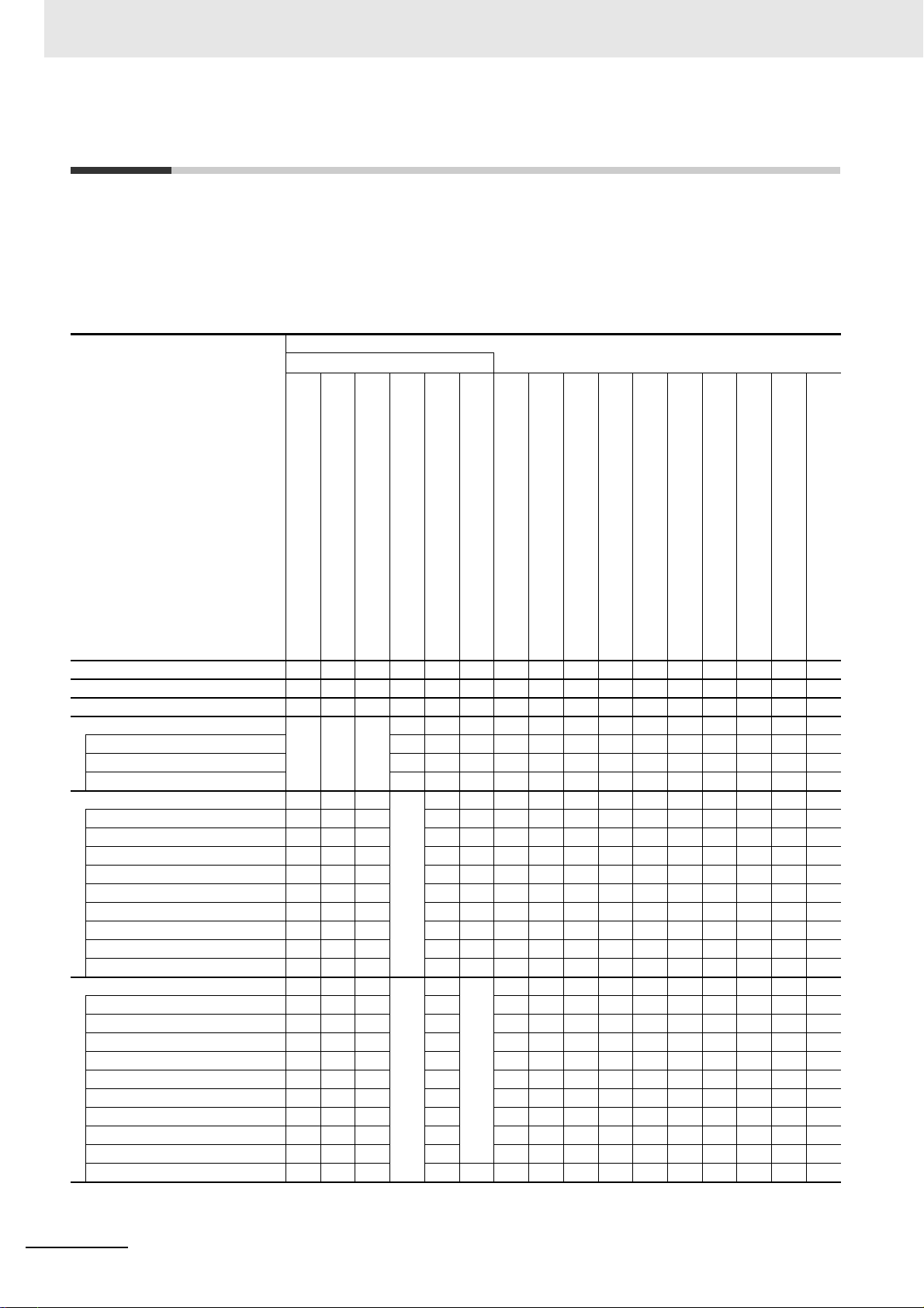
Relevant Manuals
Relevant Manuals
The following table provides the relevant manuals for the NJ/NX-series CPU Units.
Read all of the manuals that are relevant to your system configuration and application before you use
the NJ/NX-series CPU Unit.
Most operations are performed from the Sysmac Studio Automation Soft ware. Refer to the Sysmac Stu-
dio Version 1 Operation Manual (Cat. No. W504) for information on the Sysmac Studio.
Basic information
NX-series CPU Unit
Hardware User’s Manual
NX-series NX1P2 CPU Unit
Hardware User's Manual
Hardware User’s Manual
Manual
NJ-series CPU Unit
NJ/NX-series CPU Unit
Software User’s Manual
NX-series NX1P2 CPU Unit
Built-in I/O and Option Board User's Manual
NJ/NX-series
Instructions Reference Manual
Motion Control User’s Manual
NJ/NX-series CPU Unit
Motion Control Instructions Reference Manual
NJ/NX-series
NJ/NX-series CPU Unit
Built-in EtherCAT Port User’s Manual
Built-in EtherNet/IP Port User’s Manual
NJ/NX-series CPU Unit
NJ-series CPU Unit OPC UA
User’s Manual
NJ/NX-series Database Connection CPU Units
User’s Manual
NJ-series SECS/GEM CPU Units
User’s Manual
NJ-series NJ Robotics
CPU Unit User’s Manual
NJ/NY-series NC Integrated Controller
User’s Manual
NJ/NX-series
Troubleshooting Manual
Purpose of use
Introduction to NX701 CPU Units
Introduction to NX1P2 CPU Units
Introduction to NJ-series Controllers
Setting devices and hardware
Using motion control
Using EtherCAT
Using EtherNet/IP
Software settings
Using motion control
Using EtherCAT
Using EtherNet/IP
Using OPC UA
Using the database connection service
Using the GEM Services
Using robot control
Using numerical control
Using the NX1P2 CPU Unit functions
Writing the user program
Using motion control
Using EtherCAT
Using EtherNet/IP
Using OPC UA
Using the database connection service
Using the GEM Services
Using robot control
Using numerical control
Programming error processing
Using the NX1P2 CPU Unit functions
2
NJ/NX-series Troubleshooting Manual (W503)
Page 5
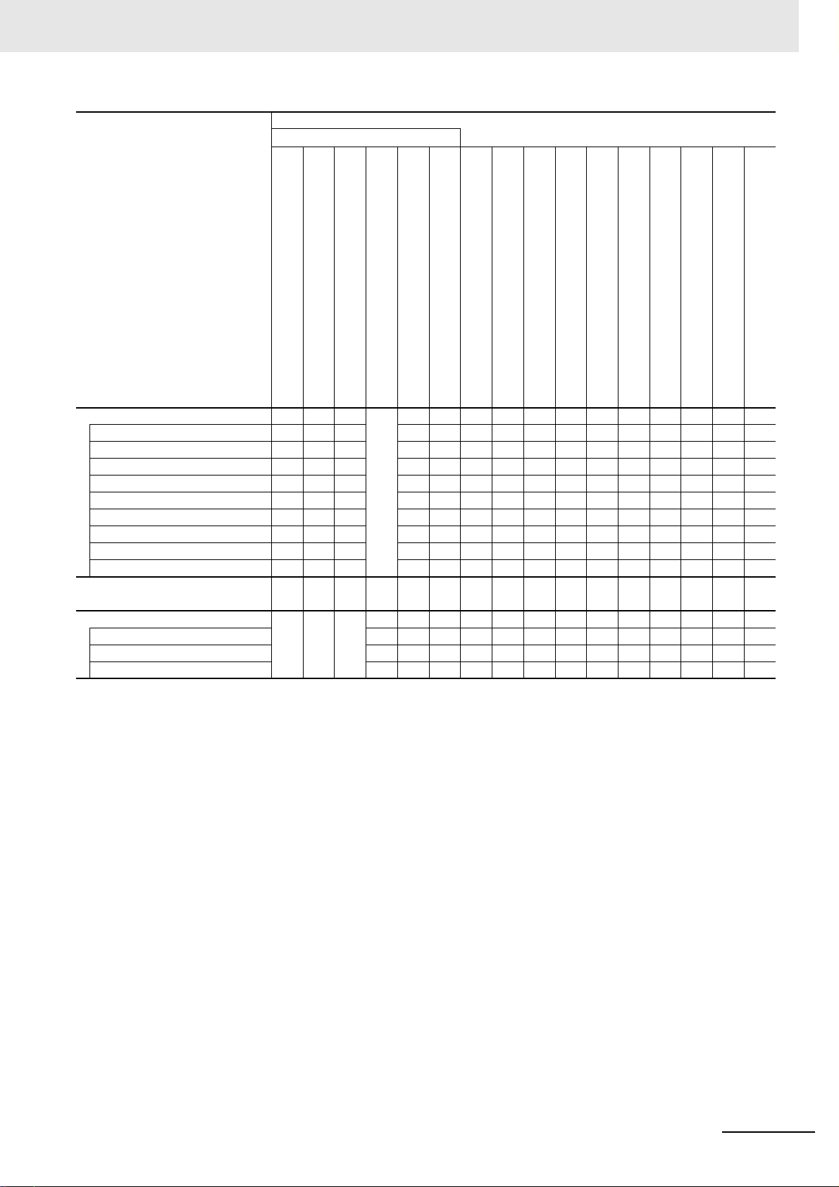
Relevant Manuals
Manual
Basic information
NX-series CPU Unit
Hardware User’s Manual
Purpose of use
Testing operation and debugging
Using motion control
Using EtherCAT
Using EtherNet/IP
Using OPC UA
Using the database connection service
Using the GEM Services
Using robot control
Using numerical control
Using the NX1P2 CPU Unit functions
Learning about error management
and corrections
Maintenance
Using motion control
Using EtherCAT
Using EtherNet/IP
*1
NX-series NX1P2 CPU Unit
Hardware User's Manual
NJ-series CPU Unit
Hardware User’s Manual
NJ/NX-series CPU Unit
Software User’s Manual
NX-series NX1P2 CPU Unit
Built-in I/O and Option Board User's Manual
NJ/NX-series
Instructions Reference Manual
Motion Control User’s Manual
NJ/NX-series CPU Unit
Motion Control Instructions Reference Manual
NJ/NX-series
NJ/NX-series CPU Unit
Built-in EtherCAT Port User’s Manual
Built-in EtherNet/IP Port User’s Manual
NJ/NX-series CPU Unit
NJ-series CPU Unit OPC UA
User’s Manual
User’s Manual
NJ/NX-series Database Connection CPU Units
NJ-series SECS/GEM CPU Units
User’s Manual
CPU Unit User’s Manual
NJ-series NJ Robotics
User’s Manual
NJ/NY-series NC Integrated Controller
Troubleshooting Manual
NJ/NX-series
*1 Refer to the NJ/NX-series Troubleshooting Manual (Cat. No. W503) for the error management concepts and an overview of the error
items. Refer to the manuals that are indicated with triangles for details on errors for the corresponding Units.
NJ/NX-series Troubleshooting Manual (W503)
3
Page 6
Manual Structure
4-9
4 Installation and Wiring
NJ-series CPU Unit Hardware User’s Manual (W500)
stinU gnitnuoM 3-4
4
stnenopmoC rellortnoC gnitcennoC 1-3-4
4-3 Mounting Units
The Units that make up an NJ-series Controller can b e co nn ec te d si m pl y b y p re s si n g t h e U n i t s t o g e t h e r
and locking the sliders by moving them toward the bac k o f th e U nit s . T he End Co ver is connect ed i n t he
same way to the Unit on the far right side of the Controller.
1 Join the Units so that the connectors fit exactly.
2 The yellow sliders at the top and bottom of each Unit lock the Units together. Move the sliders
toward the back of the Units as shown below until they click into place.
Precautions for Correct UsePrecautions for Correct Use
4-3-1 Connecting Controller Components
Connector
Hook
Hook holes
Slider
Lock
Release
Move the sliders toward the back
until they lock into place.
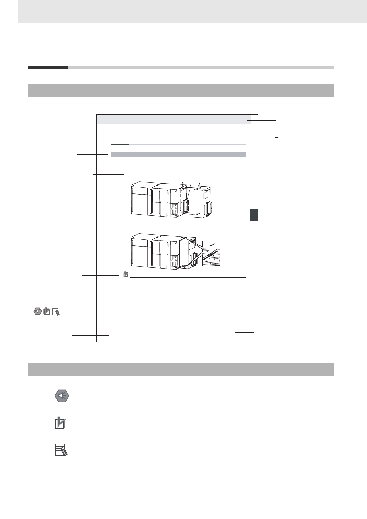
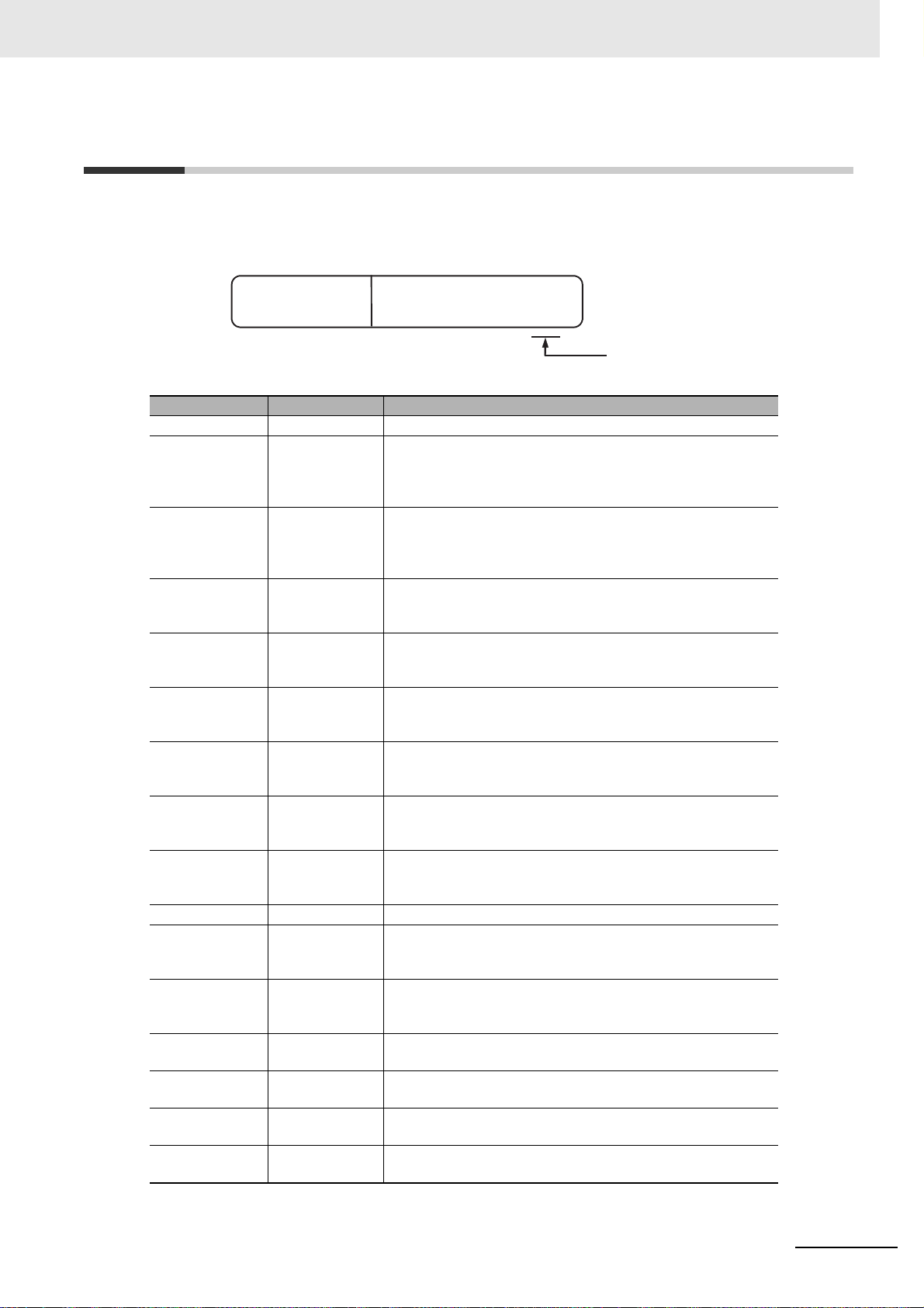
Level 1 heading
Level 2 heading
Level 3 heading
Level 2 heading
A step in a procedure
Manual name
Special information
Level 3 heading
Page tab
Gives the current
headings.
Indicates a procedure.
Icons indicate
precautions, additional
information, or reference
information.
Gives the number
of the main section.
This illustration is provided only as a sample. It may not literally appear in this manual.
The sliders on the tops and bottoms of the Power Supply Unit, CPU Unit, I/O Units, Special I/O
Units, and CPU Bus Units must be completely locked (until they click into place) after connecting
the adjacent Unit connectors.
Manual Structure
Page Structure
The following page structure is used in this manual.
Special Information
Special information in this manual is classified as follows:
Precautions for Safe Use
Precautions on what to do and what not to do to ensure safe usage of the product.
Precautions for Correct Use
Precautions on what to do and what not to do to ensure proper operation and performance.
Additional Information
Additional information to read as required.
This information is provided to increase understanding or make operation easier.
4
Note References are provided to more detailed or related information.
NJ/NX-series Troubleshooting Manual (W503)
Page 7

Precaution on Terminology
In this manual, “download” refers to transferring data from the Sysmac Studio to the physical Controller
and “upload” refers to transferring data from the physical Controller to the Sysmac Studio.
For the Sysmac Studio , synchronization is used to both upload and download data . Here, “synchronize”
means to automatically compare the data for the Sysmac Studio on the computer with the data in the
physical Controller and transfer the data in the direction that is specified by the user.
Manual Structure
NJ/NX-series Troubleshooting Manual (W503)
5
Page 8

Manual Structure
6
NJ/NX-series Troubleshooting Manual (W503)
Page 9
Sections in this Manual
1
2
3
1
2
3
A
Overview of Errors
Error Troubleshooting Methods
Error Tables
Appendix
A
I
Index
I
Sections in this Manual
NJ/NX-series Troubleshooting Manual (W503)
7
Page 10

CONTENTS
CONTENTS
Introduction ...............................................................................................................1
Relevant Manuals......................................................................................................2
Manual Structure.......................................................................................................4
Sections in this Manual ............................................................................................7
Terms and Conditions Agreement.........................................................................10
Safety Precautions..................................................................................................12
Precautions for Safe Use........................................................................................13
Precautions for Correct Use...................................................................................14
Regulations and Standards....................................................................................15
Versions ...................................................................................................................17
Related Manuals......................................................................................................21
Revision History......................................................................................................25
Section 1 Overview of Errors
1-1 Overview of NJ/NX-series Errors ........................................................................................... 1-2
1-1-1 Types of Errors............................................................................................................................1-3
1-1-2 CPU Unit Status..........................................................................................................................1-4
1-2 Fatal Errors...............................................................................................................................1-7
1-2-1 Types of Fatal Errors...................................................................................................................1-7
1-2-2 Checking for Fatal Errors........................... .................................................................................1-8
1-3 Non-fatal Errors .......................................................................................................................1-9
1-3-1 Types of Non-fat al Errors............................................... ... .................................... ......................1-9
1-3-2 Checking for Non-fatal Errors....................................................................................................1-19
1-3-3 Resetting Non-fatal Errors.........................................................................................................1-22
Section 2 Error Troubleshooting Methods
2-1 Troubleshooting Flowcharts...................................................................................................2-2
2-1-1 Checking to See If the CPU Unit Is Operating............................................................................2-2
2-1-2 Troubleshooting Flowchart for Non-fatal Errors ..........................................................................2-4
2-2 Troubleshooting Fatal Errors .................................................................................................2-5
2-3 Troubleshooting Non-fatal Errors.......................................................................................... 2-7
2-3-1 Identifying and Resetting Errors with the Sysmac Studio............................................................2-7
2-3-2 Identifying and Resetting Errors with an HMI............................................................................2-11
2-3-3 Identifying and Resetting Errors from the User Program..........................................................2-14
2-3-4 Checking for Errors with System-defined Variables..................................................................2-16
2-4 Troubleshooting When You Cannot Go Online from the Sysmac Studio ........................2-18
2-4-1 Causes and Correction When You Cannot Go Online from the Sysmac Studio.......................2-18
2-4-2 Troubleshooting for Each Cause...............................................................................................2-20
8
NJ/NX-series Troubleshooting Manual (W503)
Page 11

CONTENTS
Section 3 Error Tables
3-1 Errors by Source ............................................... .... ... .......................................... ... ... ... ............ 3-2
3-1-1 Interpreting Error Descriptions.................................................................................................... 3-2
3-1-2 Errors in the PLC Function Module............................................................................................. 3-2
3-1-3 Errors in the NX Bus Function Module ......... ... ......................................................................... 3-61
3-1-4 Errors in the Motion Control Function Module..........................................................................3-64
3-1-5 Errors in the EtherNet/IP Function Module...............................................................................3-95
3-1-6 Errors in the EtherCAT Master Function Module......................................................................3-99
3-1-7 Errors in OPC UA................................................................................................................... 3-104
3-1-8 Errors in the DB Connection Service Function ....................................................................... 3-108
3-1-9 Errors in GEM Services................................................................. ..........................................3-114
3-1-10 Errors in Robot Control Function.............................................................................................3-119
3-1-11 Errors in CNC Fu nction...........................................................................................................3-134
3-1-12 Errors in Slave Terminals........................................................................................................ 3-150
3-1-13 Errors in EtherCAT Slaves...................................................................................................... 3-190
3-1-14 Errors in CJ-series Units.........................................................................................................3-223
3-2 An Error Log Table for CJ-series Special Units................................................................ 3-243
3-3 Events in Order of Event Codes.........................................................................................3-248
3-3-1 Interpreting Error Descriptions................................................................................................ 3-248
3-3-2 Error Table..............................................................................................................................3-249
3-4 Instruction Error Table......................... .... ... ... ... .... ... ... .......................................... ... ... .... .... 3-296
Appendix
Index
A-1 Applicable Range of the HMI Troubleshooter.......................................................................A-2
A-1-1 Combinations of HMIs and CPU Units That Enable Using the Troubleshooter..........................A-2
A-1-2 System Configuration Elements Supported by the Troubleshooter ............................................A-3
A-2 Correspondence of NX Bus Events between NX1P2 CPU Units and Slave Terminals.....A-4
NJ/NX-series Troubleshooting Manual (W503)
9
Page 12

Terms and Conditions Agreement
Terms and Conditions Agreement
Warranty, Limitations of Liability
Warranties
Exclusive Warranty
Omron’s exclusive warranty is that the Products will be free from defects in materials and workmanship for a period of twelve months from the date of sale by Omro n (or such other period expr essed in
writing by Omron). Omron disclaims all other warranties, express or implied.
Limitations
OMRON MAKES NO WARRANTY OR REPRESENTATION, EXPRESS OR IMPLIED, ABOUT
NON-INFRINGEMENT, MERCHANTABILITY OR FITNESS FOR A PARTICULAR PURPOSE OF
THE PRODUCTS. BUYER ACKNOWLEDGES THAT IT ALONE HAS DETERMINED THAT THE
PRODUCTS WILL SUITABLY MEET THE REQUIREMENTS OF THEIR INTENDED USE.
Omron further disclaims all warranties and responsibility of any type for claims or expenses based
on infringement by the Products or otherwise of any intellectual property right.
Buyer Remedy
Omron’s sole obligation hereunder shall be, at Omron ’s election, to (i) replace (in the form o rig inal ly
shipped with Buyer responsible for labor charges for removal or replacement thereof) the non-complying Product, (ii) repair the non-complying Product, or (iii) repay or credit Buyer an amount equal
to the purchase price of the non-complying Product; provided that in no event shall Omron be
responsible for warranty, repair, indemnity or any other claims or expenses regarding the Products
unless Omron’s analysis confirms that the Products were properly handled, stored, installed and
maintained and not subject to contamination, abuse, misuse or inappropriate modification. Return of
any Products by Buyer must be approved in writing by Omron before shipment. Omron Companies
shall not be liable for the suitability or unsuitability or the results from the use of Products in combination with any electrical or electronic components, circuits, system assemblies or any other materials or substances or environments. Any advice, recommendations or information given orally or in
writing, are not to be construed as an amendment or addition to the above warranty.
See http://www.omron.com/global/ or contact your Omron representative for published information.
Limitation on Liability; Etc
OMRON COMPANIES SHALL NOT BE LIABLE FOR SPECIAL, INDIRECT, INCIDENTAL, OR CONSEQUENTIAL DAMAGES, LOSS OF PROFITS OR PRODUCTION OR COMMERCIAL LOSS IN ANY
WAY CONNECTED WITH THE PRODUCTS, WHETHER SUCH CLAIM IS BASED IN CONTRACT,
WARRANTY, NEGLIGENCE OR STRICT LIABILITY.
Further, in no event shall liability of Omron Companies exceed the individual price of the Product on
which liability is asserted.
10
NJ/NX-series Troubleshooting Manual (W503)
Page 13

Application Considerations
Suitability of Use
Omron Companies shall not be responsible for conformity with any standards, codes or regulations
which apply to the combination of the Product in the Buyer’s application or use of the Product. At
Buyer’s request, Omron will provide applicable third party certification documents identifying ratings
and limitations of use which apply to the Product. This information by itself is not sufficient for a complete determination of the suitability of the Product in combination with the end product, machine, system, or other application or use. Buyer shall be solely responsible for determining appropriateness of
the particular Product with respect to Buyer’s application, product or system. Buyer shall take application responsibility in all cases.
NEVER USE THE PRODUCT FOR AN APPLICATION INVOLVING SERIOUS RISK TO LIFE OR
PROPERTY WITHOUT ENSURING THAT THE SYSTEM AS A WHOLE HAS BEEN DESIGNED TO
ADDRESS THE RISKS, AND THAT THE OMRON PRODUCT(S) IS PROPERLY RATED AND
INSTALLED FOR THE INTENDED USE WITHIN THE OVERALL EQUIPMENT OR SYSTEM.
Terms and Conditions Agreement
Programmable Products
Omron Companies shall not be responsib le for the user’s progr amming of a pr ogra mmab le Pr od uct, o r
any consequence thereof.
Disclaimers
Performance Data
Data presented in Omron Company websites, catalogs and other materials is provided as a guide for
the user in determining suitability and does not constitute a warranty. It may represent the result of
Omron’s test conditions, and the user must correlate it to actual application requirements. Actual performance is subject to the Omron’s Warranty and Limitations of Liability.
Change in Specifications
Product specifications and accessories may be changed at any time based on improvements and other
reasons. It is our practice to change part numbers when published ratings or features are chan ged, or
when significant construction changes are made. However, some specifications of the Product may be
changed without any notice. When in doubt, special part numbers may be assigned to fix or establish
key specifications for your application. Please consult with your Omron’s representative at any time to
confirm actual specifications of purchased Product.
Errors and Omissions
Information presented by Omron Companies has been checked and is believed to be accurate; however, no responsibility is assumed for clerical, typographical or proofreading errors or omissions.
NJ/NX-series Troubleshooting Manual (W503)
11
Page 14

Safety Precautions
Safety Precautions
Refer to the following manuals for safety precautions.
• NX-series CPU Unit Hardware User’s Manual (Cat. No. W535)
• NX-series NX1P2 CPU Unit Hardware User’s Manual (Cat. No. W578)
• NJ-series CPU Unit Hardware User’s Manual (Cat No. W500)
12
NJ/NX-series Troubleshooting Manual (W503)
Page 15

Precautions for Safe Use
Refer to the following manuals for precautio ns for th e sa fe use of the NJ/NX-series Controller.
Installation precautions are also provided for the NJ/NX-series CPU Unit and the NJ/NX-series Controller system.
• NX-series CPU Unit Hardware User’s Manual (Cat. No. W535)
• NX-series NX1P2 CPU Unit Hardware User’s Manual (Cat. No. W578)
• NJ-series CPU Unit Hardware User’s Manual (W500)
Precautions for Safe Use
NJ/NX-series Troubleshooting Manual (W503)
13
Page 16

Precautions for Correct Use
Precautions for Correct Use
Refer to the following manuals for precautions for the correct use of the NJ/NX-series Controller.
Installation precautions are also provided for th e NJ/NX-series CPU Unit and the NJ/NX-series Controller system.
• NX-series CPU Unit Hardware User’s Manual (Cat. No. W535)
• NX-series NX1P2 CPU Unit Hardware User’s Manual (Cat. No. W578)
• NJ-series CPU Unit Hardware User’s Manual (W500)
14
NJ/NX-series Troubleshooting Manual (W503)
Page 17

Regulations and Standards
Conformance to EU Directives
Applicable Directives
• EMC Directives
• Low Voltage Directive
Concepts
EMC Directive
OMRON devices that comply with EU Directives also conform to the related EMC standards so that
they can be more easily built into other devices or the overall machine. The actual products have
been checked for conformity to EMC standards.*
Whether the products conform to the standards in the system used by the customer, however, must
be checked by the customer. EMC-related performance of the OMRON devices th at comply with EU
Directives will vary depending on the configuration, wiring, and other conditions of the equipment or
control panel on which the OMRON devices are installed. The customer mu st, therefore, perform
the final check to confirm that devices and the overall machine conform to EMC standards.
* Applicable EMC (Electromagnetic Compatibility) standards are as follows:
EMS (Electromagnetic Susceptibility): EN 61131-2
EMI (Electromagnetic Interference): EN 61131-2 (Radiated emission: 10-m regulations)
Regulations and Standards
Low Voltage Directive
Always ensure that devices operating at voltag es of 50 to 1,00 0 VAC and 75 to 1,500 VDC meet the
required safety standards. The applicable directive is EN 61010-2-201.
Conformance to EU Directives
The NJ/NX-series Controllers comply with EU Directives. To ensure that the machine or device in
which the NJ/NX-series Controller is used complies with EU Directives, the Controller must be
installed as follows:
• The NJ/NX-series Controller must be installed within a control panel.
• You must use the power supply in SELV specifications for the DC power supplies connected to
DC Power Supply Units and I/O Units.
• NJ/NX-series Controllers that comply with EU Directives also conform to the Common Emission
Standard (EN 61000-6-4). Radiated emission characteristics (10-m regulations) may vary
depending on the configuration of the control panel used, other devices connected to the control
panel, wiring, and other conditions.
You must therefore confirm that the overall machine or equipment complies with EU Directives.
NJ/NX-series Troubleshooting Manual (W503)
15
Page 18
Regulations and Standards
Conformance to KC Standards
Observe the following precaution if you use NX-series Units in Korea.
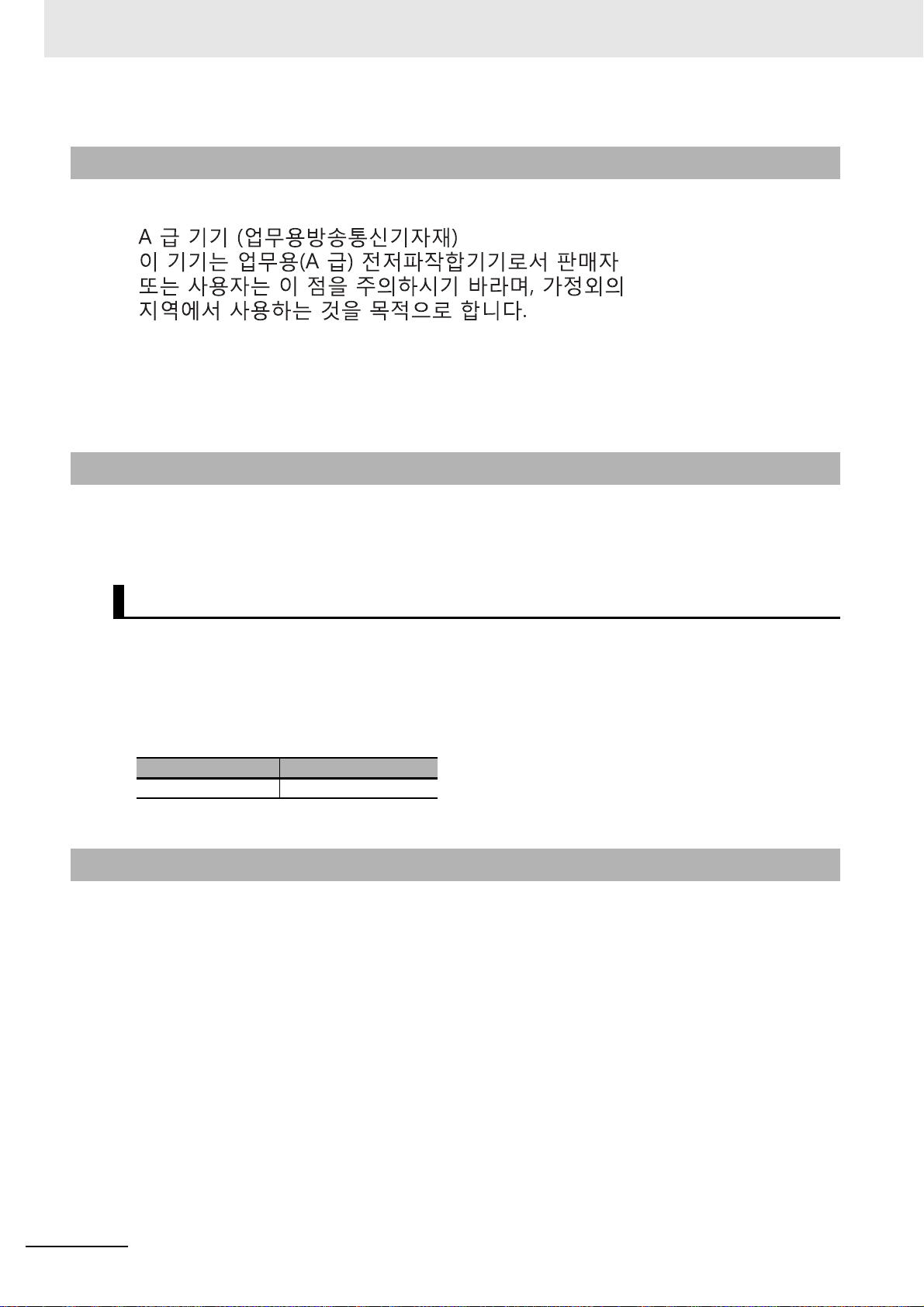
Class A Device (Broadcasting Communications Device for Office Use)
This device obtained EMC registration for office use (Class A), and it is intended to be used in places
other than homes.
Sellers and/or users need to take note of this.
Conformance to Shipbuilding Standards
The NJ/NX-series Controllers comply with the following shipbuilding standards. Applicability to the
shipbuilding standards is based on certain usage conditions. It may not be possible to use the product in some locations. Contact your OMRON represent ative before a ttempting to use a Contro ller on
a ship.
Usage Conditions for NK and LR Shipbuilding Standards
• The NJ/NX-series Controller must be installed within a control panel.
• Gaps in the door to the control panel must be completely filled or covered with gaskets or other
material.
• The following noise filter must be connected to the power supply line.
Noise Filter
Manufacturer Model
Cosel Co., Ltd. TAH-06-683
Software Licenses and Copyrights
This product incorporates certain third party software. The license and copyright information associated with this software is available at http://www.fa.omron.co.jp/nj_info_e/.
16
NJ/NX-series Troubleshooting Manual (W503)
Page 19
Versions
ID information indication
Lot number Serial number Unit version
MAC address Hardware revision
LOT No. DDMYY xxxx Ver.1.
PORT1 : HW Rev.
PORT2 :
PORT1 :
PORT2 :
Ver.1. HW Rev.
LOT No. DDMYY xxxx
ID information indication
Lot number Serial number
Unit version
MAC address
Hardware
revision
Hardware revisions and unit versions are used to manage the hardware and software in NJ/NX-series
Units and EtherCAT slaves. The hardware revision or unit version is updated each time there is a
change in hardware or software specifications. Even when two Units or EtherCAT slaves have the
same model number, they will have functional or performance differences if they have different hardware revisions or unit versions.
Checking Versions
You can check versions on the ID information indications or with the Sysmac Studio.
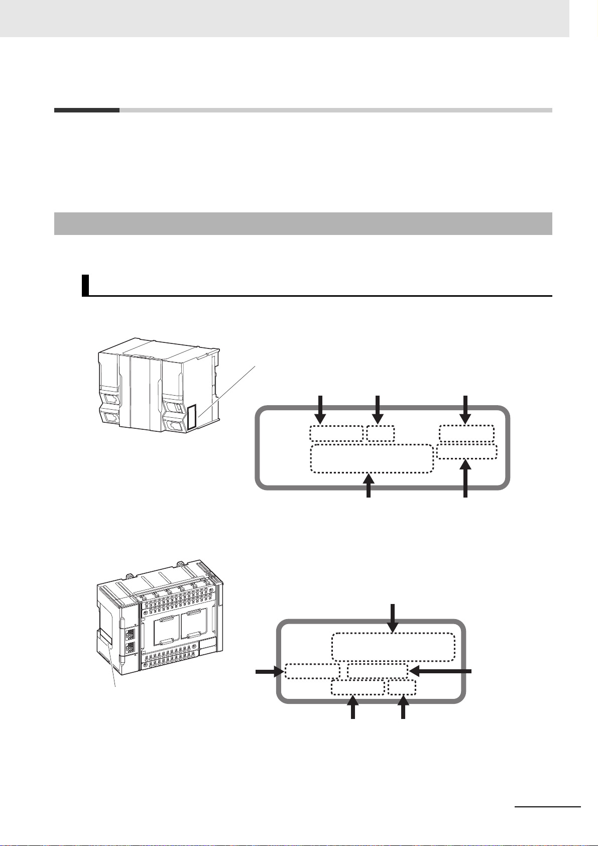
Checking Unit Versions on ID Information Indications
The unit version is given on the ID information indication on the side of the product.
The ID information on an NX-series NX701- CPU Unit is shown below.
Versions
Note The hardware revision is not displayed for the Unit that the hardware revision is in blank.
The ID information on an NX-series NX1P2- CPU Unit is shown below.
Note The hardware revision is not displayed for the Unit that the hardware revision is in blank.
NJ/NX-series Troubleshooting Manual (W503)
17
Page 20
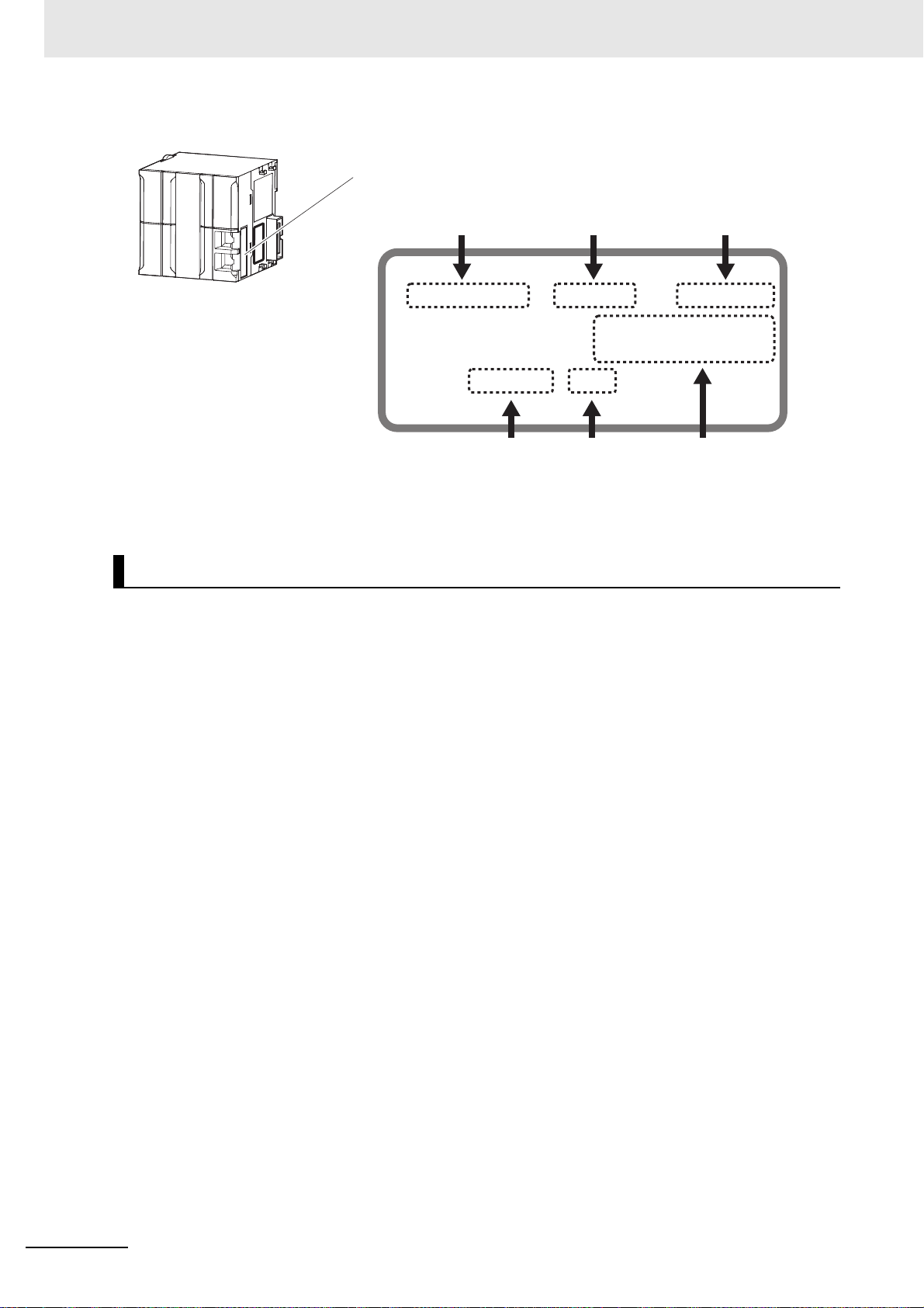
Versions
ID information indication
Unit model
Lot number Serial number MAC address
Unit version Hardware revision
NJ501
-
Ver.1.
PORT1 MAC ADDRESS:
PORT2 MAC ADDRESS:
Lot No. DDMYY
xxxx
HW Rev.
The ID information on an NJ-series NJ501- CPU Unit is shown below.
Note The hardware revision is not displayed for the Unit that the hardware revision is in blank.
Checking Unit Versions with the Sysmac Studio
You can use the Sysmac Studio to check unit versions. The procedure is different for Units and for EtherCAT slaves.
Checking the Unit Version of an NX-series CPU Unit
You can use the Production Information while the Sysmac Studio is online to check the unit version
of a Unit. You can do this for the CPU Unit. For an NX1P2 CPU Unit, you can also check the unit
versions of the NX Units on the CPU Rack and Option Boards.
1 Right-click CPU Rack under Configurations and Setup − CPU/Expansion Racks in the
Multiview Explorer and select Production Information.
The Production Information Dialog Box is displayed.
Checking the Unit Version of an NJ-series CPU Unit
You can use the Production Information while the Sysmac Studio is online to check the unit version
of a Unit. You can do this for the CPU Unit, CJ-series Special I/O Units, and CJ-series CPU Bus
Units. You cannot check the unit versions of CJ-series Basic I/O Units with the Sysmac Studio.
Use the following procedure to check the unit version.
18
1 Double-click CPU/Expansion Racks under Configurations and Setup in the Multiview
Explorer. Or, right- click CPU/Expansion Racks under Configurations and Setup and select
Edit from the menu.
The Unit Editor is displayed.
2 Right-click any open space in the Unit Editor and select Production Information.
The Production Information Dialog Box is displayed.
NJ/NX-series Troubleshooting Manual (W503)
Page 21
Versions
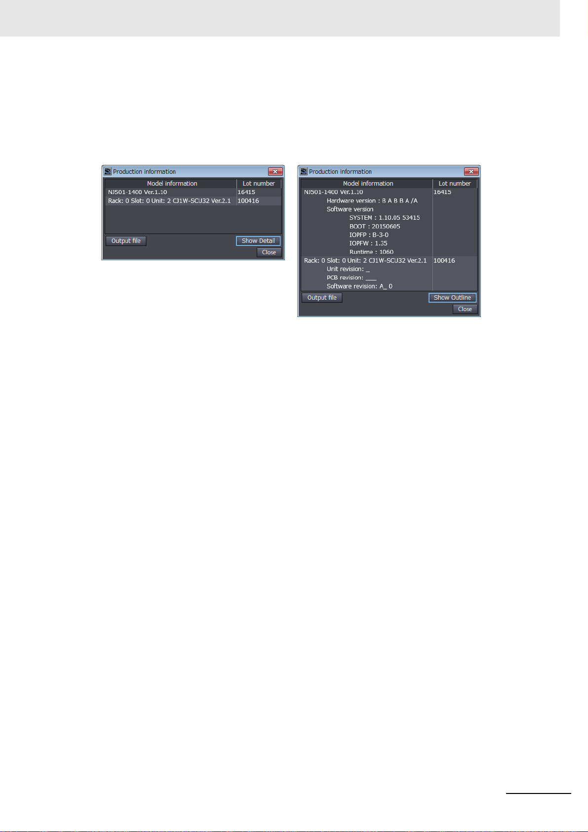
Changing Information Displayed in Production Information Dialog Box
1 Click the Show Detail or Show Outline Button at the lower right of the Production Information
Dialog Box.
The view will change between the production information details and outline.
Outline View Detail View
The information that is displayed is different for the Outline View and Detail View. The Detail View
displays the unit version, hardware version, and software versions. The Outline View displays only
the unit version.
Note The hardware revision is separated by “/” and displayed on the right of the hardware versio n. The hardware
revision is not displayed for the Unit that the hardware revision is in blank.
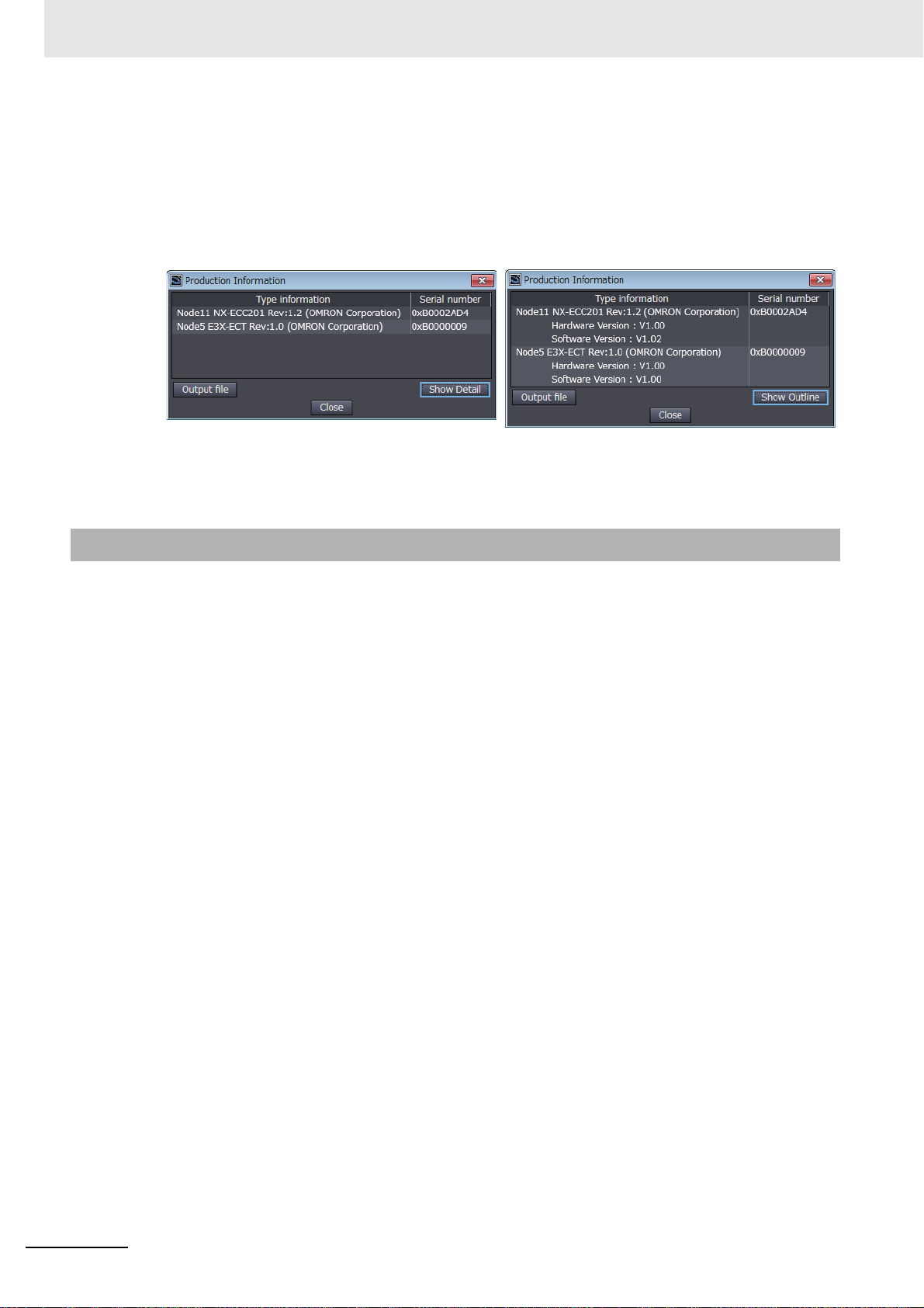
Checking the Unit Version of an EtherCAT Slave
You can use the Production Information while the Sysmac Studio is online to check the unit version
of an EtherCAT slave. Use the following procedure to check the unit version.
1 Double-click EtherCAT under Configurations and Setup in the Multiview Explorer. Or, right-
click EtherCAT under Configurations and Setup and select Edit from the menu.
The EtherCAT Tab Page is displa ye d.
2 Right-click the master on the EtherCAT Tab Page and select Display Production Information.
The Production Information Dialog Box is displayed.
The unit version is displayed after “Rev.”
NJ/NX-series Troubleshooting Manual (W503)
19
Page 22
Versions
Changing Information Displayed in Production Information Dialog Box
1 Click the Show Detail or Show Outline Button at the lower right of the Production Information
Dialog Box.
The view will change between the production information details and outline.
Outline View Detail View
Unit Versions of CPU Units and Sysmac Studio Versions
The events that can occur depend on the unit versions of the NJ/NX-series CPU Unit, the EtherCAT
slaves, and the NX Units. You must use the corresponding version of Sysmac Studio to display events
that were added for version upgrades when troubleshooting from the Sysmac Studio or from the Troubleshooter on an HMI. Refer to the product manuals for information on the unit versions of the CPU
Unit, EtherCAT slaves, and NX Units, and for the relationship with the version of the Sysmac Studio.
20
NJ/NX-series Troubleshooting Manual (W503)
Page 23

Related Manuals
The followings are the manuals related to this manual. Use these manuals for reference.
Manual name Cat. No. Model numbers Application Description
NX-series CPU Unit
Hardware User's Manual
NX-series
NX1P2 CPU Unit
Hardware
User’s Manual
NJ-series CPU Unit
Hardware User’s Manual
NJ/NX-series CPU Unit
Software User’s Manual
NX-series
NX1P2 CPU Unit
Built-in I/O and
Option Board
User’s Manual
NJ/NX-series Instructions Reference Manual
W535 NX701- Learning the basic specifi-
cations of the NX701 CPU
Units, including introductory
information, designing,
installation, and maintenance. Mainly hardware
information is provided.
W578 NX1P2- Learning the basic specifi-
cations of the NX1P2 CPU
Units, including introductory
information, designing,
installation, and maintenance.
Mainly hardware information is provided.
W500 NJ501-
NJ301-
NJ101-
W501 NX701-
NX1P2-
NJ501-
NJ301-
NJ101-
W579 NX1P2- Learning about the details
W502 NX701-
NX1P2-
NJ501-
NJ301-
NJ101-
Learning the basic specifications of the NJ-series
CPU Units, including introductory information, designing, installation, and
maintenance. Mainly hardware information is provided.
Learning how to program
and set up an NJ/NX-series
CPU Unit. Mainly software
information is provided.
of functions only for an NXseries NX1P2 CPU Unit and
an introduction of functions
for an NJ/NX-series CPU
Unit.
ning detailed specifica-
Lear
tions on the basic instructions of an NJ/NX-series
CPU Unit.
An introduction to the entire NX701 system is provided along with the following information on the
CPU Unit.
• Features and system configuration
• Introduction
• Part names and functions
• General specifications
• Installation and wiring
• Maintenance and inspection
An introduction to the entire NX1P2 system is pro-
vided along with the following information on the
CPU Unit.
• Features and system configuration
• Introduction
• Part names and functions
• General specifications
• Installation and wiring
• Maintenance and inspection
An introduction to the entire NJ-series system is
provided along with the following information on
the CPU Unit.
• Features and system configuration
• Introduction
• Part names and functions
• General specifications
• Installation and wiring
• Maintenance and inspection
The following information is provided on NJ/NX-
series CPU Units.
• CPU Unit operation
• CPU Unit features
• Initial settings
• Programming based on IEC 61131-3 language
specifications
Of the functions for an NX1P2 CPU Unit, the following information is provided.
• Built-in I/O
• Serial Communications Option Boards
• Analog I/O Option Boards
An introduction of following functions for an NJ/NXseries CPU Unit is also provided.
• Motion control functions
• EtherNet/IP communications functions
• EtherCAT communications functions
The instructions in the instruction set (IEC 61131-3
specifications) are described.
Related Manuals
NJ/NX-series Troubleshooting Manual (W503)
21
Page 24

Related Manuals
Manual name Cat. No. Model numbers Application Description
NJ/NX-series CPU Unit
Motion Control User’s
Manual
NJ/NX-series Motion
Control Instructions Reference Manual
NJ/NX-series CPU Unit
Built-in EtherCAT® Port
User’s Manual
NJ/NX-series CPU Unit
Built-in EtherNet/IP
Port User’s Manual
NJ-series
CPU Unit OPC UA
User’s Manual
NJ/NX-series Database
Connection CPU Units
User’s Manual
NJ-series SECS/GEM
CPU Units User’s Manual
NJ-series NJ Robotics
CPU Unit User’s Manual
NJ/NY-series NC Integrated Controller User’s
Manual
NJ/NY-series
G code Instructions Reference Manual
NJ/NX-series Troubleshooting Manual
Sysmac Studio V ersion 1
Operation Manual
CNC Operator
Operation Manual
NX-series EtherCAT®
Coupler Unit User’s Manual
NX-series Data
Reference Manual
W507 NX701-
NX1P2-
NJ501-
NJ301-
NJ101-
W508 NX701-
NX1P2-
NJ501-
NJ301-
NJ101-
W505 NX701-
W506 NX701-
TM
W588 NJ501-100 Using the OPC UA.
W527 NX701-20
W528 NJ501-1340 Using the GEM Services
W539 NJ501-4 Controlling robots with NJ-
O030
O031
W503 NX701-
W504 SYSMAC-
O032
W519 NX-ECC Leaning how to use an NX-
W525 NX- Referencing lists of the data
NX1P2-
NJ501-
NJ301-
NJ101-
NX1P2-
NJ501-
NJ301-
NJ101-
NJ501-20
NJ101-20
NJ501-5300
NY532-5400
NJ501-5300
NY532-5400
NX1P2-
NJ501-
NJ301-
NJ101-
SE2
SYSMAC
-RTNC0
Learning about motion control settings and programming concepts.
Learning about the specifications of the motion control
instructions that are provided by OMRON.
Using the built-in EtherCAT
port on an NJ/NX-series
CPU Unit.
Using the built-in EtherNet/IP port on an NJ/NXseries CPU Unit.
Using the database connection service with NJ/NXseries Controllers
with NJ-series Controllers
series CPU Units.
Performing numerical con-
trol with NJ/NY-series Controllers.
Learning about the specifications of the G code/M
code instructions.
Learning about the errors
that may be detected in an
NJ/NX-series Controller.
Learning about the operating procedures and functions of the Sysmac Studio.
Learning an introduction of
the CNC Operator and how
D
to use it.
series EtherCAT Coupler
Unit and EtherCAT Slave
Terminals
that is required to configure
systems with NX-series
Units.
The settings and operation of the CPU Unit and
programming concepts for motion control are
described.
The motion control instructions are described.
Information on the built-in EtherCAT port is provided. This manual provides an introduction and
provides information on the configuration, features,
and setup.
Information on the built-in EtherNet/IP port is provided. Information is provided on the basic setup,
tag data links, and other features.
Information on the OPC UA is provided.
Describes the database connection service.
Information is provided on the GEM Services.
Describes the functionality to control robots.
Describes the functionality to perform the numerical control.
The G code/M code instructions are described.
Concepts on managing errors that may be
detected in an NJ/NX-series Controller and information on individual errors are described.
Describes the operating procedures of the Sysmac
Studio.
An introduction of the CNC Operator, installation
procedures, basic operations, connection operations, and operating procedures for main functions
are described.
The system and configuration of EtherCAT Slave
T erminals, which consist of an NX-series EtherCA T
Coupler Unit and NX Units, are described along
with the hardware, setup, and functions of the EtherCAT Coupler Unit that are required to configure,
control, and monitor NX Units through EtherCAT.
Lists of the power consumptions, weights, and
other NX Unit data that is required to configure
systems with NX-series Units are provided.
22
NJ/NX-series Troubleshooting Manual (W503)
Page 25
Manual name Cat. No. Model numbers Application Description
NX-series NX Units
User’s Manuals
NX-series Safety Control
Unit User’s Manual
NX-series Safety Control
Unit Instructions Reference Manual
IO-Link System User’s
Manual
GX-series EtherCAT
Slave Units User's Manual
MX2/RX Series Inverter
EtherCAT Communication Unit User’s Manual
AC Servomotors/Servo
Drives 1S-series with
Built-in EtherCAT® Communications User’s Manual
AC Servomotors/Servo
Drives G5-series with
Built-in EtherCAT® Communications User’s Manual
EtherCAT Digital-type
Sensor Communication
Unit Operation Manual
W521 NX-ID
NX-IA
NX-OC
NX-OD
NX-MD
W522 NX-AD
NX-DA
NX-TS
W523 NX-PD1
NX-PF0
NX-PC0
NX-TBX
W524 NX-EC0
NX-ECS
NX-PG0
W540 NX-CIF
W566
W565 NX-RS
W567 NX-ILM
Z930 NX-SL
Z931 NX-SL Learnin g about the specifi-
W570 NX-ILM
W488 GX-ID
I574
I586 R88M-1
I576 R88M-K
I577 R88L-EC-
E413 E3X-ECT Learning how to connect
NX-TS
NX-HB
NX-SI
NX-SO
GX-ILM
GX-OD
GX-OC
GX-MD
GX-AD
GX-DA
GX-EC
XWT-ID
XWT-OD
GX-ILM
3G3AX-MX2-ECT
3G3AX-RX-ECT
R88D-1SN-ECT
R88D-KN-ECT
R88D-KN-ECT-L
Learning how to use NX
Units
*1
Learning how to use NXseries Safety Control Units
cations of instructions for
the Safety CPU Unit.
Learning everything from an
introduction to details about
IO-Link Systems, including
mainly software information
common to all IO-Link masters, Support Software operating methods, and
troubleshooting.
Learning how to use the
EtherCAT remote I/O
terminals.
Learning how to connect a
3G3AX-MX2-ECT or
3G3AX-RX-ECT EtherCAT
Communications Unit for
MX2/RX-series Inverters.
Learning how to use the 1Sseries AC Servomotors/Servo Drives with builtin EtherCAT Communications.
Learning how to use the AC
Servomotors/Servo Drives
with built-in EtherCAT Communications.
E3X-series EtherCAT Slave
Units.
Describes the hardware, setup methods, and functions of the NX Units.
Manuals are available for the following Units.
Digital I/O Units, Analog I/O Units, System Units,
Position Interface Units, Communications Interface
Units, Load Cell Input Units, and IO-Link Master
Units.
Describes the hardware, setup methods, and functions of the NX-series Safety Control Units.
Describes the instructions for the Safety CPU Unit.
Introduces IO-Link Systems and describes system
configurations, communications specifications,
communications methods, I/O data, parameters,
functions, Support Software, and troubleshooting.
Describes the hardware, setup methods and functions of the EtherCAT remote I/O terminals.
Describes the following information for the 3G3AXMX2-ECT and 3G3AX-RX-ECT EtherCAT Communications Unit for MX2/RX-series Inverters:
installation, parameter settings required for operation, troubleshooting, and inspection methods.
Describes the hardware, setup methods and functions of the AC Servomotors/Servo Drives with
built-in EtherCAT Communications.
Describes the hardware, setup methods and functions of the AC Servomotors/Servo Drives with
built-in EtherCAT Communications.
The linear motor type model and the model dedicated for position controls are available in
G5-series.
Provides the specifications of and describes application methods for E3X-series EtherCAT Slave
Units.
Related Manuals
NJ/NX-series Troubleshooting Manual (W503)
23
Page 26
Related Manuals
Manual name Cat. No. Model numbers Application Description
E3NW-ECT EtherCAT
Digital Sensor Communications Unit Operation
Manual
FQ-M-series Specialized
Vision Sensor for Positioning User’s Manual
FH/FZ5 Vision System
FH/FZ5 Series User’s
Manual for Communications Settings
ZW-CE1
Fiber Type Displacement Sensor User's Manual
CJ-series Special Unit
Manuals for NJ-series
CPU Unit
NA-series Programmable
Terminal Hardware
User’s Manual
NA-series Programmable
T erminal Software User’s
Manual
NS-series Programmable Terminals Programming Manual
T Confocal
*1 Temperature Input Units are introduced in Cat. No. W522 before Cat. No. W566 is released.
E429 E3NW-ECT Learning how to connect
E3NW EtherCAT Slave
Units.
Z314 FQ-MS12 Learning how to connect
FQ-M-series Specialized
Vision Sensor for Positioning.
Z342 FH-3
FH-1
Z332 ZW-CE1
W490 CJ1W-AD
CJ1W-DA
CJ1W-MAD42
W491 CJ1W-TC
W492 CJ1W-CT021
W498 CJ1W-PDC15
CJ1W-PH41U
CJ1W-AD04U
W493 CJ1W-CRM21
W494 CJ1W-SCU
W495 CJ1W-EIP21
W497 CJ1W-DRM21
Z317
V117
V118
V073 NS15-
CJ1W-V680
NA5-W
NA5-W
NS12-
NS10-
NS8-
NS5-
T Learning how to connect
Learning how to connect
FH/FZ5-series Vision Systems
ZW-CE1
Slave Units.
Learning how to use CJseries Units with an NJseries CPU Unit.
Learning the specifications
and settings required to
install an NA-series Programmable Terminals and
connect peripheral devices.
Learning about NA-series
Programmable Terminal
pages and object functions.
Learning how to use the
NS-series Programmable
Terminals.
T EtherCAT
Provides the specifications of and describes application methods for E3NW EtherCAT Slave Units.
Describes the following information for the FQ-Mseries Specialized Vision Sensor for Positioning:
installation, wiring methods, parameter settings
required for operation, troubleshooting, and
inspection methods.
The functions, settings, and communications
methods to communicate with FH/FZ5-series
Vision Systems from a PLC or other external
device are described.
Provides the specifications of and describes application methods for ZW-CE1T EtherCAT Slave
Units.
The methods and precautions for using CJ-series
Units with an NJ501 CPU Unit are described,
including access methods and programming interfaces.
Manuals are available for the following Units.
Analog I/O Units, Insulated-type Analog I/O Units,
Temperature Control Units, ID Sensor Units, Highspeed Counter Units, Serial Communications
Units, DeviceNet Units, EtherNet/IP Units, and
CompoNet Master Units.
Information is provided on NA-series Programmable T erminal specifications, part names, installation
procedures, and procedures to connect an NA Unit
to peripheral devices. Information is also provided
on maintenance after operation and troubleshooting.
NA-series Programmable Terminal pages and
object functions are described.
Describes the setup methods, functions, etc. of the
NS-series Programmable Terminals.
24
NJ/NX-series Troubleshooting Manual (W503)
Page 27
Revision History
W503-E1-18
Revision code
Cat. No.
A manual revision code appears as a suffix to the catalog number on the front and back covers of the
manual.
Revision code Date Revised content
01 July 2011 Original production
02 March 2012 Added information related to the upgrade to CPU unit version
03 May 2012 Added information related to the upgrade to CPU unit version
04 August 2012 Made additions to events and changes to the contents related
05 February 2013 Made additions to events and changes to the contents related
06 April 2013 Made additions to events and changes to the contents related
07 June 2013 Made additions to events and changes to the contents related
08 September 2013 Made additions to events and changes to the contents related
09 December 2013 Made additions to events and changes to the contents related
10 July 2014 Corrected mistakes.
1 1 January 2015 Made additions to events and changes to the contents related
12 April 2015 Made additions to events and changes to the contents related
13 April 2016 Made changes to the contents related to the upgrade to CPU
14 July 2016 Made changes to the contents related to the upgrade to CPU
15 October 2016 Made changes to the contents related to the upgrade to CPU
16 April 2017 Made changes to the contents related to the upgrade to CPU
Revision History
1.01, made additions and changes to events related to the
addition of devices that can be connected, and corrected mistakes.
1.02, made additions and changes to events related to the
addition of devices that can be connected, and corrected mistakes.
to the upgrade to CPU unit version 1.03, and corrected mistakes.
to the upgrade to CPU unit version 1.04, and corrected mistakes.
to the upgrade to CPU unit version 1.05, and corrected mistakes.
to the upgrade to CPU unit version 1.06, and corrected mistakes.
to the upgrade to CPU unit version 1.07, and corrected mistakes.
to the upgrade to CPU unit version 1.08, and corrected mistakes.
to the upgrade to CPU unit version 1.10, and corrected mistakes.
to the addition of the NX701corrected mistakes.
unit version 1.11, and corrected mistakes.
unit version 1.12, and corrected mistakes.
unit version 1.13, and corrected mistakes.
unit version 1.14, and corrected mistakes.
and NJ101-
, and
NJ/NX-series Troubleshooting Manual (W503)
25
Page 28

Revision History
17 October 2017 Made changes to th e contents related to the upgrade to CPU
18 January 2018 Made changes to the contents related to the upgrade to CPU
unit version 1.16, added an error log table for CJ-series Special Units, and corrected mistakes.
unit version 1.17, and corrected mistakes.
26
NJ/NX-series Troubleshooting Manual (W503)
Page 29

Overview of Errors
This section provides information that is required to troubleshoot errors. It introduces
the types of errors that can occur on an NJ/NX-series Controller, the operation that
occurs in response to errors, and the methods yo u can use to che ck for erro rs. Refer to
Section 2 Error Troubleshooting Methods for information on troubleshooting errors.
1-1 Overview of NJ/NX-series Errors . . . . . . . . . . . . . . . . . . . . . . . . . . . . . . . . . 1-2
1-1-1 Types of Errors . . . . . . . . . . . . . . . . . . . . . . . . . . . . . . . . . . . . . . . . . . . . . . . . 1-3
1-1-2 CPU Unit Status . . . . . . . . . . . . . . . . . . . . . . . . . . . . . . . . . . . . . . . . . . . . . . . . 1-4
1-2 Fatal Errors . . . . . . . . . . . . . . . . . . . . . . . . . . . . . . . . . . . . . . . . . . . . . . . . . . . 1-7
1-2-1 Types of Fatal Errors . . . . . . . . . . . . . . . . . . . . . . . . . . . . . . . . . . . . . . . . . . . . 1-7
1-2-2 Checking for Fatal Errors . . . . . . . . . . . . . . . . . . . . . . . . . . . . . . . . . . . . . . . . . 1-8
1-3 Non-fatal Errors . . . . . . . . . . . . . . . . . . . . . . . . . . . . . . . . . . . . . . . . . . . . . . . 1-9
1-3-1 Types of Non-fatal Errors . . . . . . . . . . . . . . . . . . . . . . . . . . . . . . . . . . . . . . . . . 1-9
1-3-2 Checking for Non-fatal Errors . . . . . . . . . . . . . . . . . . . . . . . . . . . . . . . . . . . . 1-19
1-3-3 Resetting Non-fatal Errors . . . . . . . . . . . . . . . . . . . . . . . . . . . . . . . . . . . . . . . 1-22
1
NJ/NX-series Troubleshooting Manual (W503)
1-1
Page 30
1 Overview of Errors
Precautions for Correct UsePrecautions for Correct Use
HMI
Host computer
Built-in EtherCAT port
Built-in EtherNet/IP
port
Troubleshooting functions
Troubleshooter
EtherNet/IP
EtherCAT
Sysmac Studio
CJ-series Units and NX Units
NJ/NX-series
CPU Unit
Error management range for
NJ/NX-series Controller
EtherCAT
slaves
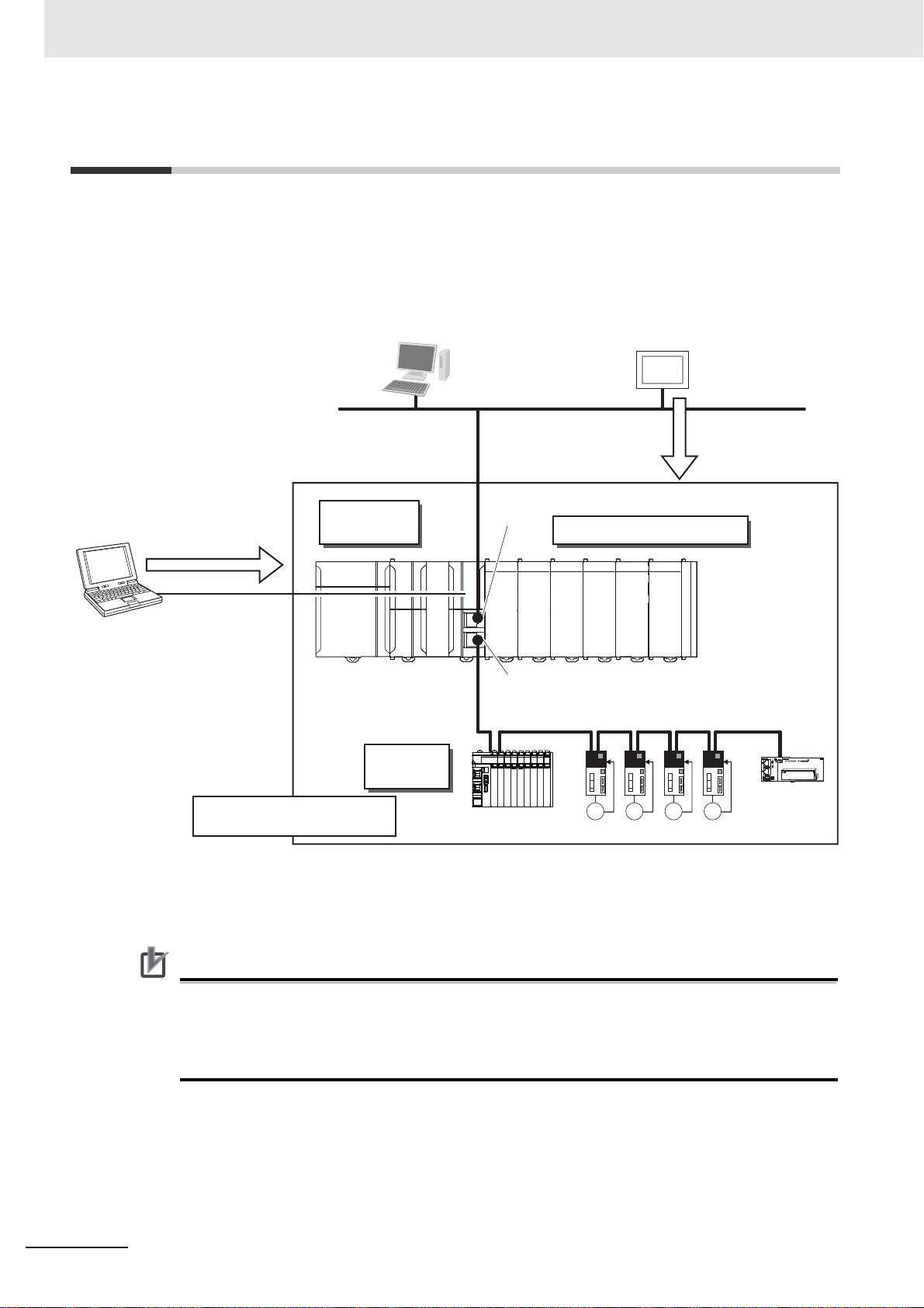
1-1 Overview of NJ/NX-series Errors
You manage all of the errors that occur on the NJ/NX-series Controller as events. The same methods
are used for all events. This allows you to see what errors have occurred and find corrections for them
with the same methods for the entire range of errors that is managed (i.e., CPU Unit, NX Units, NXseries Slave Terminals, EtherCAT slaves,* and CJ-series Units).
* Only Sysmac devices are supported. For information on EtherCAT sl aves that are Sysmac devices, refer to the
NJ/NX-series CPU Unit Built-in EtherCAT Port User’s Manual (Cat. No. W505).
1-2
You can use the troubleshooting functions of the Sysmac Studio or the Troubleshooter on an HMI to
quickly check for errors that have occurred and find corrections for them.
To perform troubleshooting from an HMI, connect the HMI to the built-in EtherNet/IP port on the CPU
Unit.
• CJ-series Units can be used only with an NJ-series CPU Unit.
• The only CPU Unit on which NX Units can be mounted is an NX1P2 CPU Unit.
• Refer to A-1 Applicable Range of the HMI Troubleshooter for the applicable range of the HMI
Troubleshooter.
NJ/NX-series Troubleshooting Manual (W503)
Page 31

1-1-1 Types of Errors
There are two main types of errors (e vents) depending on whether the NJ/NX-series Controller can
manage them or not.
Fatal Errors
These errors are not detected by the event management function of the NJ/NX-series Controller
because the CPU Unit stops operation. You cannot identify or reset these errors with the Sysmac
Studio or an HMI.
Refer to 1-2 Fatal Errors for error types and confirmation methods for fatal errors.
Non-fatal Errors
These errors are detected and mana ged with the event management functio n of the NJ/NX-series
Controller. You can confirm these errors with the Sysmac Studio or an HMI.
Refer to 1-3 Non-fatal Errors for error types and confirmation methods for non-fatal errors.
1 Overview of Errors
1-1 Overview of NJ/NX-series
Errors
1
1-1-1 Types of Errors
NJ/NX-series Troubleshooting Manual (W503)
1-3
Page 32

1 Overview of Errors
Power Supply Unit CPU Unit
RUN
ERROR
BUSY
SHTDWN
NET RUN
PORT1
EtherNet/IP
NET ERR
LINK/ACT
SD PWR
SD BUSY
L1
L2/N
L1
L2/N
AC100-2
INPUT
PWR indicator
RUN indicator
ERROR indicator
05060708091011
12
IN
010203
04
COM
00--++
POWER
RUN
ERROR
BUSY
SD PWR
SD BUSY
PORT1
EtherNet/IP
PORT1 EtherNet/IP
SW SETTING
NX1P2
POWER indicator
RUN indicator
ERROR indicator
CPU Unit
1-1-2 CPU Unit Status
You can check the ope ratin g status o f the CPU Un it with the PWR/POWER, RUN, and ER ROR indic ators on the front panels of the Power Supply Unit and CPU Unit.
NX-series CPU Units
NX701 CPU Unit
NX1P2 CPU Unit
1-4
NJ/NX-series Troubleshooting Manual (W503)
Page 33

1 Overview of Errors
Precautions for Correct UsePrecautions for Correct Use
The following table shows the status of front-p anel indicators, the st atus of user program execution, and
the ability to connect communications to the Sysmac Studio or an HMI during startup, during normal
operation, and when errors occur.
1-1 Overview of NJ/NX-series
CPU Unit operating status
Startup
Normal
operation
Fatal error in
CPU Unit
Non-fatal error
in CPU Unit
RUN mode Lit Lit Not lit Continues. Possible.
PROGRAM mode Lit Not lit Not lit Stopped.
Power Supply
Error
CPU Unit Reset
/Hardware Initialization Error
CPU Unit Error
System Initialization Error
Major fault
Partial fault
Minor fault
Observation
Power
Supply
Unit/
CPU Unit
PWR/
POWER
(green)
Lit Flashing
Not lit Not lit Not lit Stopped. Not possible.
*1
*1*2
Lit Not lit Not lit Stopped.
*1*3
Lit Not lit or
*1
Lit Flashing
*1
*4
*4
*4
*4
Lit Not lit Lit Stopped. Possible. (CommuLit Lit Flashing
Lit Lit Flashing
Lit Lit Not lit Continues.
RUN (green) ERROR (red)
(2-s intervals
followed by
0.5-s intervals)
Flashing (2-s
intervals or
0.5-s intervals)
(2-s intervals)
for 30 s or longer
CPU Unit
Not lit Stopped. Not possible.
Lit Stopped.
Not lit Stopped.
(1-s intervals)
(1-s intervals)
User pro-
gram execu-
tion status
Continues.
Continues.
*5
Communications
with Sysmac Stu-
dio or HMI
nications can be
connected from an
HMI if EtherNet/IP
is operating normally.)
Errors
1
1-1-2 CPU Unit Status
*1 Refer to 1-2 Fatal Errors for information on individual errors.
*2 This error can occur for NX701 CPU Units. If the status of indicators shown above continues 30 secon ds or longer, this
error exists.
*3 This error can occur for NX1P2 CPU Units. If the status of indicators shown above continues 30 seconds or longer, this
error exists.
*4 Refer to 1-3 Non-fatal Errors for information on individual errors.
*5 The function module where the error occurred stops.
When an NX1P2 CPU Unit is used, a power shortage may occur at the CPU Rack d ep ending on
the configuration of NX Units mounted to the CPU Unit. If one of the followings occurs, use the
Sysmac Studio to check if the power consumed by the Units on the CPU Rack exceeds the supplied power.
• The CPU Unit is operating but the mounted NX Units do not operate.
• Power is supplied to the CPU Unit, but the CPU Unit does not turn ON.
NJ/NX-series Troubleshooting Manual (W503)
1-5
Page 34

1 Overview of Errors
PWR indicator
RUN indicator
ERROR indicator
Power Supply Unit CPU Unit
NJ-series CPU Units
The following table shows the status of front-panel indi cators, the status of user progra m execution, and
the ability to connect communications to the Sysmac Studio or an HMI during startup, during normal
operation, and when errors occur.
Power
CPU Unit operating status
Supply Unit
PWR (green) RUN (green) ERROR (re d)
Startup
Normal
operation
Fatal error
in CPU
Unit
Non-fatal
error in
CPU Unit
RUN mode Lit Lit Not lit Continues. Possible.
PROGRAM mode Lit Not lit Not lit Stopped.
Power Supply Error
CPU Unit Reset
*1
Incorrect Power Supply Unit Connected
CPU Unit Watchdog
Timer Error
Major fault
Partial fault
Minor fault
Observation
*1
*2
*2
*2
*2
Lit Flashing
(1-s intervals)
*1
Not lit Not lit Not lit Stopped. Not possible.
Lit Not lit Not lit Stopped.
Lit Flashing
*1
(3-s intervals)
Lit Not lit Lit Stopped.
Lit Not lit Lit Stopped. Possible. (ComLit Lit Flashing
Lit Lit Flashing
Lit Lit Not lit Continues.
*1 Refer to 1-2 Fatal Errors for information on individual errors.
*2 Refer to 1-3 Non-fatal Errors for information on individual errors.
*3 The function module where the error occurred stops.
CPU Unit User pro-
gram execu-
tion status
Not lit Stopped. Not possible.
Lit Stopped.
Continues.
*3
(1-s intervals)
Continues.
(1-s intervals)
Communica-
tions with Sys-
mac Studio or
HMI
munications can
be connected
from an HMI if
EtherNet/IP is
operating normally.)
1-6
NJ/NX-series Troubleshooting Manual (W503)
Page 35

1 Overview of Errors
1-2 Fatal Errors
1-2-1 Types of Fatal Errors
This section describes the errors that cause the operation of the NJ/NX-series CPU Unit to stop.
The errors that can occur depend on the CPU Unit.
Communications with the Sysmac Studio or an HMI are not possible if there is a fatal error in the Controller.
Error name
Power Supply Error Yes Yes Yes
CPU Unit Reset Yes Yes
Hardware Initialization Error Yes
Incorrect Power Supply Unit Connected Yes
CPU Unit Error Yes Yes
CPU Unit Watchdog Timer Error Yes
System Initialization Error Yes Yes
1-2 Fatal Errors
1
1-2-1 Types of Fatal Errors
(Yes: Error th at can occur)
CPU Unit
NX701 NX1P2 NJ-series
The above errors are described in detail as follows.
Power Supply Error
Power is not supplied, the voltage is outside of the allowed range, or the Power Supply Unit or
power supply section is faulty.
CPU Unit Reset
The CPU Unit stopped operation because of a hardwa re erro r. For an NJ-series CPU Unit, this error
can also occur for reasons other than hardware failures, as given below.
• The power supply to an Expansion Rack is OFF.
• The I/O Connecting Cable is incorrectly installed.
• The IN and OUT connectors are reversed.
• The connectors are not mated properly.
• There is more than one I/O Control Unit on the CPU Rack or there is an I/O Control Unit on an
Expansion Rack.
Hardware Initialization Error
This error can occur for an NX1P2 CPU Unit. It indicates a dat a error in minimum program s req uired
to initialize the hardware. Only the POWER indicator will be lit while the CPU Unit is starting, but if it
is lit for 30 seconds or longer, then this error occurs.
Incorrect Power Supply Unit Connected
There is a CJ-series Power Supply Unit connected to the NJ-series CPU Unit. The ope ration of the
Controller is stopped.
NJ/NX-series Troubleshooting Manual (W503)
1-7
Page 36

1 Overview of Errors
CPU Unit Watchdog Timer Error
This error can occur for an NJ-series CPU Unit . This error occurs when the watchdog timer times
out because of a hardware failure or when temporary data corruption causes the CPU Unit to hang.
CPU Unit Error
This error can occur for an NX-series CPU Unit. It indicates that there is a hardware failure or that
the CPU is running out of control due to temporary data corruption.
System Initialization Error
This error can occur for an N X-series CPU Unit. It indicates a hardware failure or data error. The
RUN indicator will flash at 2-second intervals while the CPU Unit is starting, but if it flashes for 30
seconds or longer, then this error occurs.
1-2-2 Checking for Fatal Errors
You can identify fatal errors based on the status of the PWR/POWER, RUN, and ERROR indicators, as
well as by the ability to connect communications to the Sysmac Studio. Refer to Section 2 Error Trou-
bleshooting Methods for information on identifying errors and corrections.
NX-series CPU Units
Indicators
PWR/POWER
(green)
Not lit Not lit Not lit Not possible.* Power Supply Error
Lit Not lit Not lit CPU Unit Reset/Hardware Ini-
Lit Not lit or Flash-
Lit F lashing (2-s
* An online connection to the Sysmac Studio is necessary to differentiate between CPU Unit Resets/Hardware Ini-
tialization Errors, CPU Unit Errors, and non-fatal errors in the CPU Unit. Power Supply Errors and System Initialization Errors can be differentiated with the indicators. There is no need to see if you can go online with the CPU
Unit from the Sysmac Studio.
RUN (green) ERROR (red)
Lit CPU Unit Error
ing (2-s intervals
or 0.5-s inter-
vals)
Not lit System Ini tia lization Error
intervals) for 30 s
or longer
Communications
with Sysmac Studio
CPU Unit operating status
tialization Error
NJ-series CPU Units
Indicators
PWR (green) RUN (green) ERROR (red)
Not lit Not lit Not lit Not possible.* Power Supply Error
Lit Not lit Not lit CPU Unit Reset
Lit F lashing (3-s
intervals).
Lit Not lit Lit CPU Unit Watchdog Timer
* An online connection to the Sysmac Studio is necessary to differentiate between CPU Unit Resets, CPU Unit
Watchdog Timer Errors, and non-fatal errors in the CPU Unit. Power Supply Errors and Incorrect Power Supply
Unit Connected errors can be differentiated with the indicators. There is no need to see if you can go online with
the CPU Unit from the Sysmac Studio.
Lit Incorrect Power Supply Unit
Communications
with Sysmac Studio
CPU Unit operating status
Connected
Error
1-8
NJ/NX-series Troubleshooting Manual (W503)
Page 37

1-3 Non-fatal Errors
Precautions for Correct UsePrecautions for Correct Use
NX-series CPU Unit
Event logs
Event source
Sysmac Studio
HMI
NX Units
Backup battery
*1
Create User-defined
Error instruction:
SetAlarm
Create User-defined
Information
instruction: SetInfo
User program
Or
Check current Controller
events and the event log
of past events.
Check current Controller
events and the event log
of past events.
PLC Function
Module
Motion Control
Function Module
EtherCAT Master
Function Module
EtherNet/IP
Function Module
EtherCAT
Slave
Terminal
Event logs
EtherCAT
slave
NX Bus
Function Module
NX Units
Event logs
*1. For NX701, the event logs are saved in battery-backup memory. For NX1P2, they are saved in non-volatile memory.
Non-fatal errors that occur are managed as events in the NJ/NX-series Controller. You can check the
event to find out what type of error occurred.
1 Overview of Errors
1-3 Non-fatal Errors
1-3-1 Types of Non-fatal Errors
Overview of Controller Events (Errors and Information)
You use the same methods to manage all of the events that occur on the NJ/NX-series Controller. The
events that occur are saved in the CPU Unit or NX-series Slave Terminals.
You can use th e Sysmac Studio or an HMI to confirm current Controller even ts and the log of events
that occurred before. This log is called an event log.
To use an HMI to check events, connect the HMI to the built-in EtherNet/IP port on the CPU Unit.
The event management for NX-series Units is shown below.
1
1-3-1 Types of Non-fatal Errors
• The only CPU Unit on which NX Units can be mounted is an NX1P2 CPU Unit.
NJ/NX-series Troubleshooting Manual (W503)
1-9
Page 38

1 Overview of Errors
Precautions for Correct UsePrecautions for Correct Use
The event management for NJ-series Units is shown below.
Check current Controller
events and the event log
of past events.
Sysmac Studio
Or
HMI
Check current Controller
events and the event log
of past events.
Event source
PLC Function
Module
Backup battery
NJ-series CPU Unit
Motion Control
Function Module
Event logs
EtherCAT Master
Function Module
EtherNet/IP
Function Module
EtherCAT
Slave
Terminal
Event logs
User program
Create User-defined
Error instruction:
SetAlarm
Create User-defined
Information
instruction: SetInfo
EtherCAT
slave
CJ-series
Units
Errors in
Special Units
For an NX-series or NJ-series CPU Unit, use the following information to handle errors that
occurred in an EtherCAT Slave T erminal or EtherCAT slave.
• Refer to the manual for the Commun ications Coupler Unit for details on the event log in a
Slave Terminal.
• When there is an emergency message that notifies an error from an EtherCAT slave to the
CPU Unit, it is recorded in the event log of the EtherCAT Master Function Module as the
Emergency Message Detected (64200000 hex) event.
• You cannot confirm the event log for an EtherCAT slave that has no event log. To reco rd an
error history as an event, you have to change the setting of the EtherCA T slave to notify emergency messages, then the Emergency Message Detected (64200000 hex) event is recorded.
However, errors which cannot be notified by emergency messages from EtherCAT slaves are
not recorded in the event log.
Meanwhile, there is a way to display error histo ry of some EtherCAT slaves that do not have
the event log, on the Sysmac Studio version 1.15 or high er as the e ven t log. Refe r to releva nt
manuals for EtherCAT slaves for the possibility to display error history as the event log.
• Refer to relevant manuals for the slaves for the procedures to read error history of EtherCAT
slaves.
The following events can occur.
Controller Events
The Controller automatically detects these events. Controller events include events for the function
modules in the CPU Unit, NX Units, NX-series Slave Terminal, EtherCAT slaves, and CJ-series
Units.
1-10
NJ/NX-series Troubleshooting Manual (W503)
Page 39

1 Overview of Errors
Additional Information
Version Information
• You cannot check the error logs that are managed independently by EtherCAT slaves because
they are not for Controller events. Refer to relevant manuals for the slaves for the procedures
to read error logs and correct errors.
• Error causes and corrections are not displayed on the Controller Event Log Tab Page in the
Sysmac Studio, although error codes, which are registered in the error logs that are managed
independently by CJ-series Special Units, are displayed. Refer to relevant manuals for the
Units for the procedures to read error logs and correct errors.
User-defined Events
These are events that occur in applications that the user developed.
Refer to the NJ/NX-series CPU Unit Software User’s Manual (Cat. No. W501) for information on
user-defined events.
Non-fatal errors are managed as Controller event s. This section describes mainly the Controller events.
1-3 Non-fatal Errors
1
1-3-1 Types of Non-fatal Errors
Details on Controller Events (Errors and Information)
Controller Event Times
The time of occurrence is recorded when an event occurs.
The times of occurrence are based on the CPU Unit’s built-in clock data.
For events that occur in EtherCAT Slave Terminals, the times of occurre nce are re corded base d on
the CPU Unit’s built-in clock data that the EtherCAT Slave Terminal receives from the CPU Unit.
If the EtherCAT Slave Term inal cannot obtain the clock data from the CPU Unit, the time of occurrence on the Sysmac Studio is displayed as ----/--/-- -- :--:--. For an event occurred before the Ether-
CAT Slave Terminal obtains the clock data from the CPU Unit, the time of occurrence is also
displayed as ----/--/-- --:--:--.
If the EtherCAT Slave Terminal cannot obtain the clock data from the CPU Unit or an event
occurred before the EtherCAT Slave Terminal obtains the clock data from the CPU Unit, the time
of occurrence is displayed as 1970/1/1 0:00:00 with Sysmac Studio version 1.14 or lower.
Sources of Controller Events
The Event source information indicates the location where an event occurred. The event source
identifies the particular function module in the CPU Unit in which the event occurred. For some function modules, there is more detailed info rmation about the event source. This information is called
the Source details. The following information is provided as the event source details.
Event source Source details
PLC Function Module Instructions, power supply, built-in I/O, Option Board, I/O bus
NX Bus Function Module
Motion Control Function Module Common, axis, or axes group
EtherCAT Master Function Module Communications port, EtherCA T master, EtherCAT Coupler
EtherNet/IP Function Module Communications port, communications port 1, communications
NJ/NX-series Troubleshooting Manual (W503)
*1
master, or CJ-series Unit
Master or NX Unit
Unit, NX Unit, or EtherCAT slave
port 2, CIP, CIP1, CIP2, FTP, NTP, or SNMP
1-11
Page 40

1 Overview of Errors
*1 Only for NX1P2 CPU Units.
Note An NC Integrated Controller has the CNC Function Module. For how to check and correct errors in the CNC
Function Module, refer to the NJ/NY-series NC Integrated Controller User’s Manual (Cat. No. O030).
The event source is displayed on the Sysmac Studio or HMI.
Levels of Controller Events (Errors and Information)
The following table classifies the levels of Controller events according to the effect that the errors
have on control.
No. Level Classification Level name
1 High Controller errors Major fault level
2 Partial fault level
3 Minor fault level
4 Observation
5 Low Controller informa-
Errors with a higher level have a greater impact on the functions that the NJ/NX-series Controller
provides, and are more difficult to recover from. When an event occurs, the Sysmac Studio or HMI
will display the level name.
Information
tion
Event Levels
• Major Fault Level
These errors prevent control operations for the entire Controller. When the CPU Unit detects a
major fault, it immediately stops the execution of the user program and turns OFF the loads of all
slave, including remote I/O. With EtherCAT slaves, some NX Units, and some CJ-series Special
Units, you can set the slave settings or Unit settings to select whether outputs will go OFF or
retain their previous status. You cannot reset major fault level errors from the user progra m, the
Sysmac Studio or an HMI. To recover from a major fault level error, re move the cau se of the er r or,
and either cycle the power supply to the Controller, or reset the Controller from the Sysmac Studio.
• Partial Fault Level
These errors prevent control operations in a certain function module in the Controller. The NJ/NXseries CPU Unit continues to execute the user program even after a partial fau lt level error occur s.
You can include error processing in the user program in order to stop equipment safely. After you
remove the cause of the error, execute one of the following to return to normal status.
• Reset the error from the user program, the Sysmac Studio, or an HMI.
• Cycle the power supply.
• Reset the Controller from the Sysmac Studio.
• Minor Fault Level
These errors prevent part of the control operations in a certain function module in the Controller.
The troubleshooting for minor fault level errors is the same as the processing for partial fault level
errors.
• Observations
These errors do not affect the control operations of the Controller. The observation notifies you of
potential problems before they develop into a minor fault level error or wo rse.
• Information
Events that are classified as information provide information that do not indicate errors.
You can change the event level for some events. Refer to the NJ/NX-series CPU Unit Software User’s
Manual (Cat. No. W501) for details on changing event levels. Refer to 3-1 Error s by Source in this manual to see the events for which you can change the event level.
1-12
NJ/NX-series Troubleshooting Manual (W503)
Page 41

1 Overview of Errors
Operation for Each Level
The way that the Controller operates when an event occurs depends on the level of the Controller
event.
Level of event
Controller
information
These are not
errors, but
appear in the
event log to
notify the user
of specific information.
• Power
Turned ON
• Power Interrupted
• Memory All
Cleared
Item
Definition
Event examples
(Only a few
examples are
provided here.
Refer to Section
3 Error Tables
for a list of all of
the errors.
PWR/
POWE
*1
R
(green)
RUN
(green)
ERRO
R (red)
RUN
output
on
Power
Supply
Unit
User
program
execution
status
Outputs
turned
OFF
Error
reset
Event
logs
Frontpanel
indica-
tors
NJ/NXseries
CPU
Unit
operation
Controller errors
Major fault
level
These errors
are serious
errors that prevent control
operations for
the entire Controller.
• Non-volatile
Memory Data
Corrupted
(PLC Function)
Lit Lit Lit Lit Lit
Not lit Lit Lit Lit Lit
Lit Flashes at 1-s
OFFONONONON
Stops.
YesNoNoNoNo
Not possible. Depends on the
Recorded.
(Some errors
are not
recorded.)
Partial fault
level
These errors
prevent all of
the control in a
function module other than
PLC Function
Module.
Motion Control
•
Period Exceeded
(Motion Control
Function Module)
•
Communications Controller Failure
(EtherCAT
Master Function Module)
intervals.
Continues.
nature of the
error.
Recorded. Recorded. Recorded. Recorded.
Minor fault
level
These errors
prevent part of
the control
operations in a
certain function
module.
• Positive Limit
Input
Detected
(Motion Control Function
Module)
• Low Battery
Voltage (PLC
Function
Module)
Flashes at 1-s
intervals.
*2
Continues. Continues. Continues.
Depends on the
nature of the
error.
Observation Information
These errors do
not affect system control
operations.
• Packet Discarded Due
to Full Reception Buffer
(EtherNet/IP
Function
Module)
Not lit Not lit
--- ---
1-3 Non-fatal Errors
1
1-3-1 Types of Non-fatal Errors
NJ/NX-series Troubleshooting Manual (W503)
1-13
Page 42

1 Overview of Errors
Item
Outputs from
EtherCAT slaves
and Basic Output Units
Sysmac Studio
display (when
online)
*1 If multiple Controller errors have occurred, the indicators show the error with the highest event level.
*2 Operation stops in the function module (NX Bus Function Modu le, Motion Con trol Function Mo dule, EtherCAT
Master Function Module, or EtherNet/IP Function Module) in which the error occurred.
Level of event
Controller errors
Major fault
level
Refer to I/O
Operation for
Major Fault
Level Controller Errors on
page 1-16.
Error messages are automatically displayed in the
Controller Status Pane.
The user can display detailed information in the
Troubleshooting Dialog Box.
Partial fault
level
• Errors in Eth-
erCAT Master
Function
Module:
Depends on
settings in the
slave.
• Errors in
other function modules:
According to
user program.
Minor fault
level
According to
user program.
Controller
information
Observation Information
According to
user program.
These items are not displayed in
the error display in the Controller
Status Pane.
According to
user program.
1-14
NJ/NX-series Troubleshooting Manual (W503)
Page 43

1 Overview of Errors
Operation in the Function Module Where an Error Event Occurred
Function
module
PLC Function
Module
NX Bus Function
Module
Motion Control
Function Module
EtherCAT Master
Function Module
EtherNet/IP Function Module
Major fault level Partial fault level Minor fault level Observation
User program execution
stops.
--- I/O refreshing for NX
--- All axes stop. (The
--- EtherCAT communi-
--- EtherNet/IP commu-
Level of current event
--- Operation continues.
Operation continues. If
bus communications
stops.
(NX Unit operation
depends on the NX
Unit settings.)
stop method depends
on the error.)
cations stop. (The
slaves operate
according to the settings in the slaves.)
nications stop.
(Online connections
to the Sysmac Studio
and communications
connections with an
HMI is not possible.)
an NX Unit error occurs,
operation depends on
the fail-soft operation
settings.
• The affected
axes/axes group
stops. (The stop
method depends on
the settings.)
• The motion control
instruction is not executed (for instructions
related to axis operation.)
I/O refreshing for EtherCAT communications
stops or continues
according to the fail-soft
operation settings in the
master. (If I/O refreshing
stops, the slaves operate according to the settings in the slaves.)
Part of EtherNet/IP communications stop.
(Online connections to
the Sysmac Studio and
communications connections with an HMI is
possible if the online
connections or communications connection is
not the cause of the
error.)
Operation continues.
• Axis operation
continues.
• The motion control instruction is
not executed (for
instructions not
related to axis
operation).
I/O refreshing for
EtherCAT communications continues.
EtherNet/IP communications continue.
1-3 Non-fatal Errors
1
1-3-1 Types of Non-fatal Errors
NJ/NX-series Troubleshooting Manual (W503)
1-15
Page 44

1 Overview of Errors
I/O Operation for Major Fault Level Controller Errors
The following table gives the operation of the CPU Unit and the I/O devices.
Unit CPU Unit operation Unit or slave operation
NX Unit mounted to the CPU Unit
Built-in I/O
Option Board
NX-series Slave Terminal The NX-series Slave Terminal
EtherCAT slave
Servo Drive or NX Unit assigned to
an axis
CJ-series Basic I/O Unit
CJ-series Special Unit
Devices connected with EtherNet/IP • For the originators of tag data
*1
*1
*2
*1
Input refreshing stops. Depends on the settings for the NX
Unit.
• Depends on the Load Rejection
Output Setting.
• Input refreshing stops.
• Outputs turned OFF. Output val-
ues depend on the specifications
of the Option Board.
• Input refreshing stops.
moves to Safe-Operational state.
The slave is placed in the Safe-
Operational state.
Updating the command values is
stopped.
*4
*4
• The values of all outputs are
cleared to zero.
• Input refreshing continues.
Refreshing continues. Depends on the Unit operating
links, the variables and I/O memory addresses for input (consume) tags are not refreshed.
• For the targets of tag data links,
operation depends on the settings of the tags sets for the out-
put (produce) tags.
*5
---
Analog I/O Option Board
• Output value: 0 V
Depends on the NX Unit settings.
Depends on the slave settings.
All axes stop immediately.
• All outputs are turned OFF.
• External inputs are refreshed.
specifications.
Depends on the specifications of
the connected devices.
*3
*1 This applies to an NX1P2 CPU Unit.
*2 Excluding Servo Drives assigned to an axis.
*3 Settings and setting methods depend on the slave. Refer to the manual for the slave. For a Servo Drive, oper-
ation depends on the setting of object 605E hex (Fault Reaction Option Code).
*4 This applies to an NJ-series CPU Unit.
*5 You can set whether to clear output or maintain the data from before the error occurred. Refer to the NJ/NX-
series CPU Unit Built-in EtherNet/IP Port User’s Manual (Cat. No. W506) for details.
The following table gives the operation of the CPU Unit and the I/O devices for the following errors
that occur for an NJ-series Unit.
• Unsupported Unit Detected
• I/O Bus Check Error
• End Cover Missing
• Incorrect Unit/Expansion Rack Connection
• Duplicate Unit Number
• Too Many I/O Points
• I/O Setting Check Error
1-16
NJ/NX-series Troubleshooting Manual (W503)
Page 45
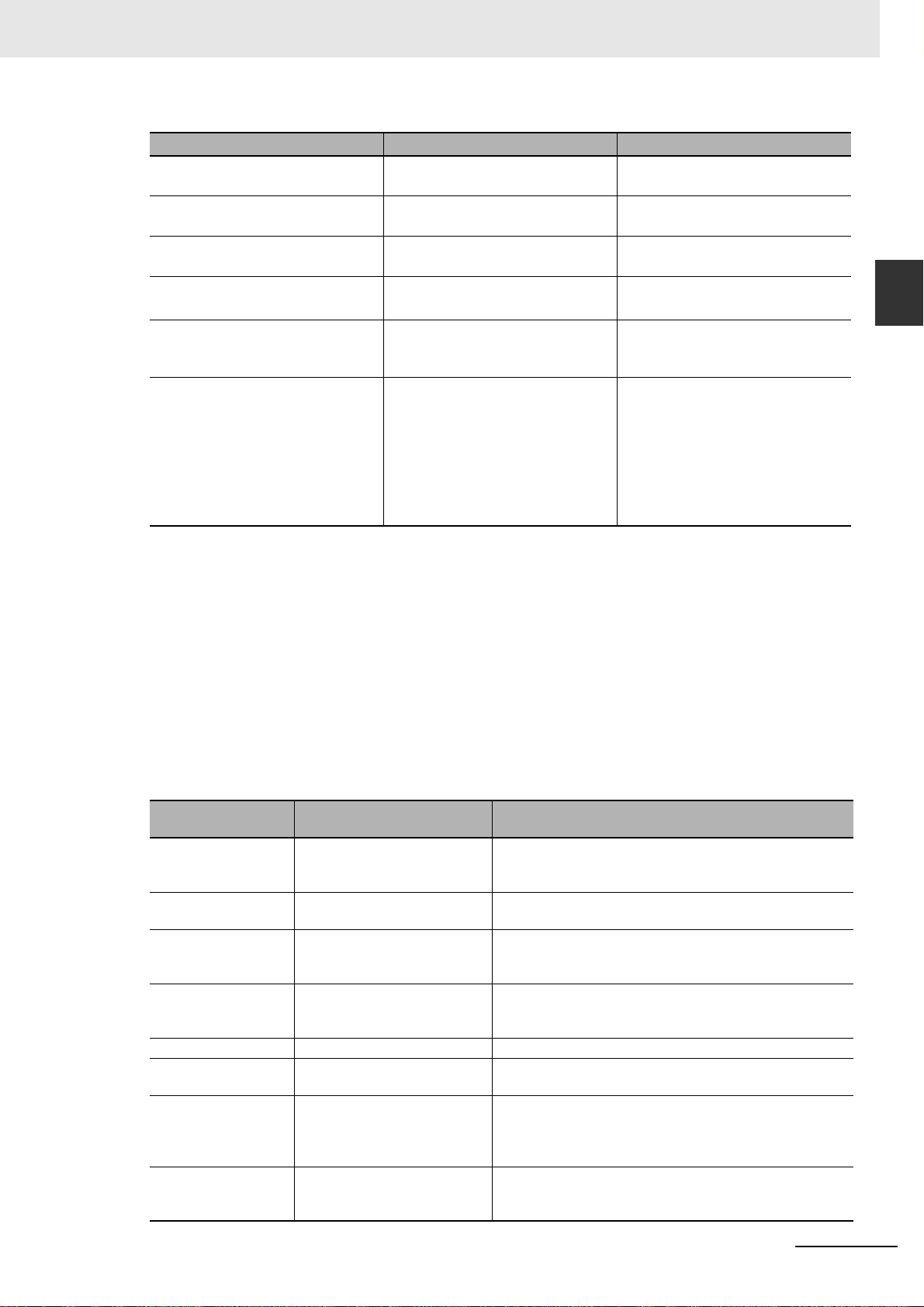
1 Overview of Errors
Unit CPU Unit operation Unit or slave operation
EtherCAT Slave Terminal The EtherCAT Slave Terminal
moves to Safe-Operational state.
EtherCAT slave
Servo Drive or NX Unit assigned to
an axis
CJ-series Basic I/O Unit Refreshing is stopped. • All outputs are turned OFF.
CJ-series Special Unit Refreshing is stopped. Depends on the Unit operating
Devices connected with EtherNet/IP • For the originators of tag data
*1
The slave is placed in the SafeOperational state.
Updating the command values is
stopped.
links, the variables and I/O memory addresses for input (consume) tags are not refreshed.
• For the targets of tag data links,
operation depends on the settings of the tags sets for the out-
put (produce) tags.
*3
Depends on the NX Unit settings.
Depends on the slave settings.
All axes stop immediately.
• All inputs are turned OFF.
specifications (the ERH indicator
lights).
Depends on the specifications of
the connected devices.
1-3 Non-fatal Errors
*2
1
1-3-1 Types of Non-fatal Errors
*1 Excluding Servo Drives assigned to an axis.
*2 Settings and setting methods depend on the slave. Refer to the manual for the slave. For a Servo Drive, ope r-
ation depends on the setting of object 605E hex (Fault Reaction Option Code).
*3 You can set whether to clear output or maintain the data from before the error occurred. Refer to the NJ/NX-
series CPU Unit Built-in EtherNet/IP Port User’s Manual (Cat. No. W506) for details.
Event Code
Events that occur in a Controller have an event code. When an event occurs, the Sysmac Studio or
HMI will display the event code. You can use the instructions that get error status to read the error
codes of current errors from the user program.
The event codes are 8-digit hexadecimal values. The first digit of a Controller event represents its
category. These categories are listed in the table below.
First digit of the
code (hex)
0 Hardware errors An error caused by a hardware problem such as an
1 Data errors An error caused by incorrectly saved data or data cor-
2 Hardware setting errors An error caused by incorrect handling of hardware set-
3 Configuration errors An error caused by incorrect parameter values, parame-
4 Software errors An error caused by Controller software.
5 User software errors An error that is c aused by the user program. (For exam-
6 Observation errors An error that was detected in monitoring operation that
7 Control errors An error caused by a control process. (For example, if
Classification Meaning
internal part malfunction, contact failure, temperature
error, undervoltage, overvoltage, or overcurrent.
ruption in the Controller.
tings (e.g., hardware switches) or restrictions (e.g., Unit
assignment locations).
ters and hardware configurations that do not match, or
configurations set by the user.
ple, an input value to an instruction that is out of range.)
occurs due to user settings in the Controller. (For example, if the task period is exceeded or if a position outside
of the motion range is detected.)
the operating status does not meet the required conditions or if the timing is incorrect.)
NJ/NX-series Troubleshooting Manual (W503)
1-17
Page 46

1 Overview of Errors
First digit of the
code (hex)
8 Communications errors An error caused by communication s with an external
9 Information Events that are classified as information and provide
Classification Meaning
device or host system.
information that do not indicate errors.
Relationship between Event Codes and Error Codes
In addition to the event codes that indicate errors, the function modules and Units have their own
error codes. If there are correspondin g event and error co des, you can tell what the other code is if
you know either one of them. This allows you to know when the same error is being given when you
check errors with more than one method.
The following table shows the relationship between the error codes and event codes.
Error code (4-digit hexadecimal)
Classification Used in Upper 4 digits Lower 4 digits
Error codes in the
Motion Control
Function Module
Error codes for basic
instructions, OPC
UA instructions, DB
Connection instructions, GEM instructions and CNC
instructions.
Error codes for robot
control function
Error codes in CJseries Special Units
• ErrorID output
variable for motion
control instructions
• System-defined
variables for
motion control*
ErrorID output variable for each
instructions
• ErrorID output
variable for robot
instructions
• System-defined
variables for
motion control
Error logs from CJseries Special Units
*
Corresponding event code
(8-digit hexadecimal)
Error code 0000 hex A1230000 hex
5401 hex Error code 5401A123 hex
Error code 0000 hex A1230000 hex
0000 hex Error code 0000A123 hex
Example: Event
code for an error
code of A123 hex
1-18
* The following are system-defined variables for motion control:
Variable Name
_MC_COM.PFaultLvl.Code MC Common Partial Fault Code
_MC_COM.MFaultLvl.Code MC Common Minor Fault Code
_MC_COM.Obsr.Code MC Common Observation Code
_MC_AX[].MFaultLvl.Code Axis Minor Fault Code
_MC_AX[].Obsr.Code Axis Observation Code
_MC_GRP[].MFaultLvl.Code Axes Group Minor Fault Code
_MC_GRP[].Obsr.Code Axes Group Observation Code
Exporting the Error Log
You can use the Sysmac Studio or an HMI to export the displayed event log to a CSV file. Refer to
the NJ/NX-series CPU Unit Software User’s Manual (Cat. No. W501) for information on exporting
event logs
NJ/NX-series Troubleshooting Manual (W503)
Page 47

1-3-2 Checking for Non-fatal Errors
Checking Methods
Use the following methods to check for non-fatal errors.
Checking method What you can check
Checking the indicators You can use the indicators to confirm the Controller error level, the error
status of the EtherCAT Master Func tion Module, and the error status of
the EtherNet/IP Function Module.
Checking with the Troubleshooting
Function of Sysmac Studio
Checking with the Troubleshooter of
*2
an HMI
Instructions that read function mod-
ule error status
Checking with system-defined vari-
ables
*1 Detailed information, such as error causes and corrections, is not displayed.
*2 To perform troubleshooting from an HMI, connect the HMI to the built-in EtherNet/IP port on the CPU Unit.
Refer to A-1 Applicable Range of the HMI Troubleshooter for the applicable range of the HMI Troubleshooter.
This section describes the above checking methods.
You can check for curren t Con trol ler errors, a log of past Controller
errors, error sources, error causes, and corrections. You can also check
error logs from CJ-series Special Units.
You can check for curren t Con trol ler errors, a log of past Controller
errors, error sources, error causes, and corrections.
You can check the high est-level status and highest-level event code in
the current Controller errors.
You can check the cu rrent Controller error status for each function mod-
ule.
1 Overview of Errors
1-3 Non-fatal Errors
1
1-3-2 Checking for Non-fatal Errors
*1
Checking the Indicators
Checking the Level of a Controller Error
You can use the PWR/POWER, RUN, and ERROR indicators to determine the level of an error. The
following table shows the relationship between the Controller’s indicators and the event level.
Indicators
PWR/POWER
(green)
Lit Not lit Lit Major fault level
Lit Lit Flashing
Lit Lit Not lit Observation
RUN (green) ERROR (red)
(1-s intervals).
Checking the Status of EtherCAT and EtherNet/IP Ports
For the EtherCAT and EtherNet/IP ports, use the EtherCAT and EtherNet/IP NET ERR indicators to
determine whether an erro r that affects process data communications has occurred and whether a
minor fault level error or higher-level error has occurred. The indicators let you check the status
given in the following table.
Indicators Indicated status
EtherCAT
NET ERR
EtherCAT Port Status
• Lit: Errors for which normal status cannot be recovered through user actions (i.e., errors
for which you must replace the CPU Unit or contact your OMRON representative).
• Flashing: Errors for which normal status can be recovered through user actions.
• Not lit: An error that affects process data communications has not occurred.
Event level
Partial fault level
Minor fault level
NJ/NX-series Troubleshooting Manual (W503)
1-19
Page 48

1 Overview of Errors
Precautions for Correct UsePrecautions for Correct Use
Indicators Indicated status
EtherNet/IP
NET ERR
Checking with the Troubleshooting Function of Sysmac Studio
When an error occurs, you can connect the Sysmac Studio online to the Controller to check current
Controller errors and the log of past Controller errors.
Current Errors
Open the Sysmac Studio’s Controller Error Tab Page to check the current error’s level, source,
source details, event name, event code, details, attached information 1 to 4, actions, and corrections. Errors are not displayed for observations.
Log of Past Errors
EtherNet/IP Port Stat us
• Lit: Errors for which normal status cannot be recovered through user actions (i.e., errors
for which you must replace the CPU Unit or contact your OMRON representative).
• Flashing: Errors for which normal status can be recovered through user actions.
• No lit: There are no minor fault level or higher-level errors.
Open the Sysmac Studio’s Controller Event Log Tab Page to check the times, levels, sources,
source details, event names, event codes, details, attached information 1 to 4, actions, and corrections for previous errors.
Error logs from CJ-series Special Units are displayed on the Controller Event Log Tab Page.
Detailed information is not displayed. To check detailed information, use the event codes that are
displayed and refer to the error codes that are given in the manual for the relevant Unit. The relationship between error codes and event codes is described in Details on Controller Events (Errors and
Information) under 1-3-1 Types of Non-fatal Errors.
Refer to the Sysmac Studio Version 1 Operation Manual (Cat. No. W504) for details on trouble-
shooting with the Sysmac Studio.
Checking with the Troubleshooter of an HMI
When an error occurs, if you can connect communications be tween an HMI a nd th e Contr oller, you can
check current Controller errors and the log of past Controller errors.
To perform troubleshooting from an HMI, connect the HMI to the built-in EtherNet/IP port on the CPU
Unit.
Refer to A-1 Applicable Range of the HMI Troubleshooter for the applicable range of the HMI
Troubleshooter.
Current Errors
You can check the current error’s event name, event code, level, source, source details, time,
details, and attached information 1 to 4.
Also, observations are not displayed as errors.
Log of Past Errors
You can check the time, level, source, source details, event name, event code, details, attached
information 1 to 4 for past errors.
Refer to the relevant HMI manual for information on the HMI Troubleshooter.
1-20
NJ/NX-series Troubleshooting Manual (W503)
Page 49

1 Overview of Errors
Instructions That Read Function Module Error Status
You can dete rmine the err or status with the instru ctions that get error status provided for each function
module from the user progr am. These instructions get the status and the event cod e of the error with
the highest level.
Applicable function module Instruction name Instruction
PLC Function Module Get PLC Controller Error Status GetPLCError
Get I/O Bus Error Status GetCJBError
NX Bus Function Module Get NX Bus Error Status GetNXBError
Get NX Unit Error Status GetNXUnitError
Motion Control Function Module Get Motion Control Error Status GetMCError
EtherCAT Master Function Mod-
ule
EtherNet/IP Function Module Get EtherNet/IP Error Status GetEIPError
Note An NC Integrated Controller has the CNC Function Module. For how to check and correct errors in the CNC
Function Module, refer to the NJ/NY-series NC Integrated Controller User’s Manual (Cat. No. O030).
Get EtherCAT Error Status GetECError
1-3 Non-fatal Errors
1
1-3-2 Checking for Non-fatal Errors
For details on the instructions that get error status, refer to the NJ/NX-series Instructions Reference
Manual (Cat. No. W502).
Checking with System-defined Variables
You can check the Error Status variable in the system-defined variables to determine the status of
errors in a Controller. You can read the Error Status variable from an external device by using communications. Refer to the NJ/NX-series CPU Unit Software User’s Manual (Cat. No. W501) for information
on system-defined variables.
NJ/NX-series Troubleshooting Manual (W503)
1-21
Page 50

1 Overview of Errors
Precautions for Safe Use
Precautions for Correct UsePrecautions for Correct Use
1-3-3 Resetting Non-fatal Errors
Unless you reset an error, the C PU Unit will retain the error status until you turn OFF the power supply
to the Controller or reset the Controller.
To reset a Controller error, it is necessary to eliminate the cause of the error. The same error will occur
again if you reset the error, but do not eliminate the cause of the error.
Always confirm safety at the connected equipment before you reset Controller errors with an
event level of partial fault or higher for the EtherCAT Master Fun ction Mo dule. Whe n th e er ror is
reset, all slaves that were in any state other than Operational state (in which outputs are disabled) due to the Controller error with an event level of partial fault or higher will go to Operational state and the outputs will be enabled. Before you reset all errors, confirm that no Controller
errors with an event level of partial fault have occurred for the EtherCAT Master Function Module.
Always confirm safety at the connected equipment before you rese t Controller errors for a CJseries Special Unit. When the Controller error is reset, the Unit where the Controller error with an
event level of observation or higher will be restarted. Before you reset all errors, confirm that no
Controller errors with an event level of observation or higher have occurred for the CJ-series
Special Unit. Observation level events do not appear on the Controller Error Tab Page, so it is
possible that you may restart the CJ-series Special Unit without intending to do so. You can
check the status of the _CJB_UnitErrSta[0,0] to _CJB_UnitErrSta[3,9] Error Status variables on
a Watch Tab Page to see if an observation level Controller error has occurred.
Resetting an error is not the same as eliminating the cause of the error. Always eliminate the
cause of an error before you perform the procedure to reset the error.
1-22
NJ/NX-series Troubleshooting Manual (W503)
Page 51

Error Resetting Methods
1 Overview of Errors
1-3 Non-fatal Errors
Method Operation
Commands from
Sysmac Studio
Commands from an
*2
HMI
Commands from the
user program
Commands from a
host computer
Resetting Controller
errors
Downloading Resetting all errors
Clear All Memory Resetting all errors
Controller reset After the causes of the Controller errors are
Clear All Memory
operation for Slave
Terminal
Restarting the Slave
Terminal
Resetting Controller
errors
Resetting Controller
errors
Resetting Controller
errors with CIP messages
Errors that are
reset
Resetting all errors
in the entire Controller
Resetting all Slave
Terminal errors
Resetting errors for
individually specified NX Units
for a specific function module
for all function modules
Resetting all Slave
Terminal errors
Resetting all errors
in the entire Controller
Resetting errors for
individual function
modules
Resetting all errors
for all function modules
Description
Reset the Controller errors from the Sysmac Studio’s Troubleshoo ting Dialog Box.
Refer to the manual for the Communications Coupler Unit for details on resetting
errors in a Slave Terminal.
For NX Units connected to the NX bus of
the CPU Unit, reset the Controller error individually from the Sysmac Studio’s Troubleshooting Dialog Box.
Refer to the manual for the Communications Coupler Unit for details on resetting
errors individually for NX Units mounted to
a Slave Terminal.
After the causes of the Controller errors are
removed, all Controller errors in the relevant function module are reset as a result.
Errors are not reset when you download the
Controller Configurations and Setup.
After the causes of the Controller errors are
removed, all Controller errors in all function
modules are reset as a result. Errors for
Slave Terminals are not reset.
removed, all Controller errors in all function
modules are reset as a result. Errors for
Slave Terminals are not reset.
If the causes for the Controller errors are
removed, all Controller errors in the Slave
Terminals are reset.
Reset Controller errors from the Troubleshooter of an HMI.
Y ou can reset errors from an HMI that is not
directly compatible with the NJ/NX-series
Controller or another company’s HMI if you
use the HMI in combination with the reset
error instruction for the function module in
the user program.
Execute the reset error instruction for the
function module in the user program.
• For the Motion Control Function Module,
you can reset all errors, errors for a particular axis, or errors for a particular axes
group.
• For the NJ-series I/O bus, you can reset
all errors or just the errors for a particular
Unit.
• For the NX Bus Function Module, only
resetting all errors is possible.
Use a CIP message from a host computer
to reset errors.
*1
*1
1
1-3-3 Resetting Non-fatal Errors
NJ/NX-series Troubleshooting Manual (W503)
1-23
Page 52

1 Overview of Errors
Method Operation
Cycling the Controller’s power supply
Cycling the power
supply to the Slave
Terminal
*1 Some errors are reset when the EtherCA T communications link is established rather than when the reset oper-
ation is performed.
*2 To reset errors from an HMI, connect the HMI to the built-in EtherNet/IP port on the CPU Unit.
--- Resets all errors. After the causes of the Controller errors are
--- Resetting all Slave
Errors that are
reset
Terminal errors
Description
removed, all Controller errors in all function
modules are reset as a result.
If the causes for the Controller errors are
removed, all Controller errors in the Slave
Terminals are reset.
Refer to the Sysmac Studio Version 1 Operation Manual (Cat. No. W504) for details on clearing errors
from the Sysmac Studio.
1-24
NJ/NX-series Troubleshooting Manual (W503)
Page 53

Error Troubleshooting Methods
This section describes troubleshooting methods for specific errors.
2-1 Troubleshooting Flowcharts . . . . . . . . . . . . . . . . . . . . . . . . . . . . . . . . . . . . . 2-2
2-1-1 Checking to See If the CPU Unit Is Operating . . . . . . . . . . . . . . . . . . . . . . . . . 2-2
2-1-2 Troubleshooting Flowchart for Non-fatal Errors . . . . . . . . . . . . . . . . . . . . . . . . 2-4
2-2 Troubleshooting Fatal Errors . . . . . . . . . . . . . . . . . . . . . . . . . . . . . . . . . . . . 2-5
2-3 Troubleshooting Non-fatal Errors . . . . . . . . . . . . . . . . . . . . . . . . . . . . . . . . . 2-7
2-3-1 Identifyi ng and Resetting Errors with the Sysmac Studio . . . . . . . . . . . . . . . . 2-7
2-3-2 Identifyi ng and Resetting Errors with an HMI . . . . . . . . . . . . . . . . . . . . . . . . .2-11
2-3-3 Identifying and Resetting Errors from the User Program . . . . . . . . . . . . . . . . 2-14
2-3-4 Checking for Errors with System-defined Variables . . . . . . . . . . . . . . . . . . . . 2-16
2-4 Troubleshooting When You Cannot Go Online from the
Sysmac Studio . . . . . . . . . . . . . . . . . . . . . . . . . . . . . . . . . . . . . . . . . . . . . . . 2-18
2-4-1 Causes and Correcti on When You Cannot Go Online fro m the
Sysmac Studio . . . . . . . . . . . . . . . . . . . . . . . . . . . . . . . . . . . . . . . . . . . . . . . . 2-18
2-4-2 Troubleshooting for Each Cause . . . . . . . . . . . . . . . . . . . . . . . . . . . . . . . . . . 2-20
2
NJ/NX-series Troubleshooting Manual (W503)
2-1
Page 54

2 Error Troubleshooting Methods
PWR/POWER
indicator (green)?
ERROR indicator (red)?
Not possible.
Not possible.
Error occurs.
Not lit.
Lit.
Lit.
Not lit.
Power Supply Error
CPU Unit Reset/Hardware
Initialization Error
CPU Unit Error
A
Possible.
Possible.
RUN indicator (green)?
Flashing (2-s intervals)
for 30 s or longer
Not lit.
System Initialization Error
RUN indicator (green)?
Flashing (at 2-s intervals
or 0.5-s intervals)
Not lit.
Flashing.
Communications
with Sysmac
Studio?
Communications
with Sysmac
Studio?
A fatal error occurred in the CPU Unit.
Refer to 2-2 Troubleshooting Fatal
A non-fatal error occurred. Refer to 2-1-2
Troubleshooting Flowchart for Non-fatal
Errors.
2-1 Troubleshooting Flowcharts
This section provides basic error identification and troubleshooting flowcharts. Use them when an error
occurs in the NJ/NX-series Controller.
2-1-1 Checking to See If the CPU Unit Is Operating
When an error occurs in the NJ/NX-series Controller, use the following flowchart to determine whether
the error is a fatal error or a non-fatal error.
Whenever possible, set the Sysmac Studio’s software connection method in the flowchart to a direct
USB connection if the CPU Unit has a USB (peripher al) port. If you use Ethernet , there are many re asons that prevent a software connection from the Sysmac Studio, so time is required to determine if a
fatal or non-fatal error has occurr ed. If you cannot go online from the Sysmac Studio, perform 2-4 Trou-
bleshooting When You Cannot Go Onlin e from the Sysmac Studio before you assume that the error is a
fatal error.
NX-series CPU Units
2-2
NJ/NX-series Troubleshooting Manual (W503)
Page 55

2 Error Troubleshooting Methods
Flashing.
Not possible.
Not
possible.
Error occurs.
RUN indicator (green)?
Not lit.
Lit.
Lit.
Not lit.
Not lit.
Power Supply Error
CPU Unit Reset
CPU Unit Watchdog Timer Error
Incorrect Power Supply Unit Connected
A
Possible.
Possible.
PWR indicator
(green)?
ERROR indicator
(red)?
Communications with
Sysmac Studio?
Communications with
Sysmac Studio?
Flashing.
A fatal error occurred. Refer to 2-2
Troubleshooting Fatal Errors.
A non-fatal error occurred. Refer to 2-1-2
T roubleshooting Flowchart for Non-fatal
Errors.
NJ-series CPU Units
2-1 Troubleshooting Flowcharts
2
2-1-1 Checking to See If the CPU Unit Is Operating
NJ/NX-series Troubleshooting Manual (W503)
2-3
Page 56

2 Error Troubleshooting Methods
Precautions for Correct UsePrecautions for Correct Use
A
Lit.
Not lit.
Flashing.
Lit.Lit.
Flashing.Flashing.
Check all of the following branches that correspond to the
status of the EtherNet/IP NET ERR and EtherCAT NET
ERR indicators.
EtherNet/IP NET ERR indicator is lit or flashing.
EtherCAT NET ERR indicator is
lit or flashing.
Major fault
level
Observation
Error in the
EtherNet/IP port for
which you cannot
restore normal status
by yourself.
Error in the
EtherNet/IP port for
which you can
restore normal status
by yourself.
Error in the
EtherCAT port for
which you cannot
restore normal
status by yourself.
Error in the
EtherCAT port for
which you can
restore normal
status by yourself.
Error in PLC
Function Module or
MC Function
Module
To immediately check the
specific error
Non-fatal error
To check error status with the indicators
Both indicators are not lit.
Partial fault level or
minor fault level
ERROR indicator (red)?
EtherCAT NET ERR
indicator (red)?
EtherNet/IP NET ERR
indicator (red)?
Troubleshoot the error with the Sysmac Studio or HMI.
Refer to 2-3 Troubleshooting Non-fatal Errors.
2-1-2 Troubleshooting Flowchart for Non-fatal Errors
For a non-fatal error, use the Sysmac Studio or an HM I to trouble shoo t the er ro r with the following flowchart. You can use the indicators to check the following:
• Level
• Whether the error is in the EtherNet/IP port or the EtherCAT port
• If the sources of the error is the EtherNet/IP port or the EtherCAT port, whether you can restore nor-
mal status yourself
Refer to A-1 Applicable Range of the HMI Troubleshooter for the applicable range of the HMI
Troubleshooter.
2-4
NJ/NX-series Troubleshooting Manual (W503)
Page 57

2 Error Troubleshooting Methods
2-2 Troubleshooting Fatal Errors
The section describes the procedure to troubleshoot fatal errors.
Power Supply Error
Cause Correction
Power is not being input. Turn ON the power.
The voltage is outside of the allowable
range for the power supply.
Power supply system error caused by
mounted Unit
Power Supply Unit failure (CPU Units
other than NX1P2)
Power supply section failure (NX1P2
CPU Unit)
Check the Controller’s power supply system, and correct it so that the
voltage is within the allowable range.
Remove the Units from the CPU Rack one by one. If the error is eliminated, replace that Unit.
If the error persists even after you make the above corrections,
replace the Power Supply Unit.
If the error persists even after you make the above corrections,
replace the CPU Unit.
2-2 Troubleshooting Fatal Errors
2
System Initialization Error
Cause Correction
A conductive object has gotten inside. If there is conductive material nearby, blow out the CPU Unit with air.
Noise If the error did not result from the above causes, cycle the power to
the Controller and see if that resets th e error. If the error occurs frequently, check the FG and power supply lines to see if noise is entering on them. Implement noise countermeasures as required.
CPU Unit failure If the error persists even after you make the above corrections,
replace the CPU Unit.
CPU Unit Reset
Cause Correction
A conductive object has gotten inside. If there is conductive material nearby, blow out the CPU Unit with air.
The power supply to an Expansion Rack
is OFF.
The I/O Connecting Cable is incorrectly
installed.
Noise If the error did not result from the above causes, cycle the power to
Power Supply Unit failure If the error persists even after you make the above corrections,
CPU Unit failure If the error persists even after you make the above corrections,
Supply the correct voltage to the Power Supply Unit on the Expansion
Rack.
Correct the connection of the I/O Connecting Cable.
the Controller and see if that resets th e error. If the error occurs frequently, check the FG and power supply lines to see if noise is entering on them. Implement noise countermeasures as required.
replace the Power Supply Unit.
replace the CPU Unit.
NJ/NX-series Troubleshooting Manual (W503)
2-5
Page 58

2 Error Troubleshooting Methods
Hardware Initialization Error
Cause Correction
A conductive object has gotten inside. If there is conductive material nearby, blow out the CPU Unit with air.
Noise If the error did not result from the above causes, cycle the power to
CPU Unit failure If the error persists even after you make the above corrections,
Incorrect Power Supply Unit Connected
Cause Correction
A CJ-series Power Supply Unit is connected to an NJ-series CPU Unit.
CPU Unit Error
the Controller and see if that resets the error. If the error occurs frequently, check the FG and power supply lines to see if noise is entering on them. Implement noise countermeasures as required.
replace the CPU Unit.
Connect an NJ-series Power Supply Unit to the NJ-series CPU Unit.
Cause Correction
A conductive object has gotten inside. If there is conductive material nearby, blow out the CPU Unit with air.
Noise If the error did not result from the above causes, cycle the power to
the Controller and see if that resets the error. If the error occurs frequently, check the FG and power supply lines to see if noise is entering on them. Implement noise countermeasures as required.
CPU Unit failure If the error persists even after you make the above corrections,
replace the CPU Unit.
CPU Unit Watchdog Timer Error
Cause Correction
A conductive object has gotten inside. If there is conductive material nearby, blow out the CPU Unit with air.
Noise If the error did not result from the above causes, cycle the power to
the Controller and see if that resets the error. If the error occurs frequently, check the FG and power supply lines to see if noise is entering on them. Implement noise countermeasures as required.
CPU Unit failure If the error persists even after you make the above corrections,
replace the CPU Unit.
2-6
NJ/NX-series Troubleshooting Manual (W503)
Page 59

2 Error Troubleshooting Methods
2-3 Troubleshooting Non-fatal Errors
2-3-1 Identifying and Resetting Errors with the Sysmac Studio
Troubleshooting functions are provided by the Sysmac Studio. You can use the troubleshooting functions to identify errors that occur in a Controller, and reset the errors.
Displaying Errors on the Sysmac Studio
If an error occurs while the Sysmac St udio is online with the CPU Unit, the Sysmac Studio notifies the
user of the error in the Controller Status Pane. From there, you can open the Troubleshooting and
Event Logs Window to read detailed error information and troubleshooting methods.
Click the Troubleshooting Button in the toolbar, or select Troubleshooting from the Tools Menu.
2-3 Troubleshooting Non-fatal Errors
2
2-3-1 Identifying and Resetting Errors with the Sysmac Studio
The Sysmac Studio automatically collects the Controller’s error information, and opens the Troubleshooting Window.
NJ/NX-series Troubleshooting Manual (W503)
2-7
Page 60

2 Error Troubleshooting Methods
Checking Current Errors and the Event Logs with the Sysmac
Studio
Checking Current Errors with the Sysmac Studio
You can click the Controller Errors Tab in the Troubleshooting Window to read information on current errors in the Controller.
The Controller Errors Tab Page lists the current errors in order of their levels.
Display item Description
Level This is the event level of the error.
Source and Source Details This is the physical location and functional location of the error.
Event Name Error name
Event Code This is the code of the error.
You can click the column headings in the Controller error list, such as the Level or Source, to reorder
the table rows according to that heading. For example, the following change occurs when you click
the Source heading.
Before Source heading is clicked.
↓
After Source heading is clicked.
2-8
NJ/NX-series Troubleshooting Manual (W503)
Page 61

2 Error Troubleshooting Methods
Displaying Event Logs with the Sysmac Studio
With Sysmac Studio, you can check a log of the Controller events that previously occurred on the
Controller Event Log Tab Page.
You can selec t the event logs and levels to display in the Display Settings Area. Information on the
events that you specify are displayed in the detailed information area.
2-3 Troubleshooting Non-fatal Errors
2
2-3-1 Identifying and Resetting Errors with the Sysmac Studio
Error logs from CJ-series Special Units are displayed on the Controller Event Log Tab Page.
Detailed information is not displayed. To check detailed information, use the event codes that are
displayed and refer to the error codes that are given in the manual for the relevant Unit. The relationship between error codes and event codes is described in Details on Controller Events (Errors and
Information) under 1-3-1 Types of Non-fatal Errors.
Resetting Errors with the Sysmac Studio
You can use the Sysmac Studio to reset errors that occur in a Controller. With a CPU Unit with unit version 1.05 or later and Sysmac Studio version 1.06 or higher you can also reset errors for individual
Units.
Before you attempt to reset a Controller error, isolate and remove the cause of the error.
The Troubleshooting Dialog Box displays the cause, source, and corrections for the error. You can
select any of the items from the error list to display the following information about that error. Click the
Display Switch Button to switch between displaying details and attached information and displaying
actions and corrections.
Display item Description
Details Detailed information on the error is displayed, such as the probable causes.
Attached information 1
through 4
Action and Correction Methods to correct the probable causes of the error are displayed.
After confirming the cause of the displayed error and the conditions in which it occurred, perform the
displayed error corrections to eliminate the cause of the error.
Detailed information about the source of the error is displayed.
NJ/NX-series Troubleshooting Manual (W503)
2-9
Page 62

2 Error Troubleshooting Methods
To eliminate the cause of the error, first select the item to perform from the Action and Correction list.
When you select the appropriate step in the Action and Correction list, either the Jump to Error or
Error Help Button is enabled, depending on the contents. In some cases, neither button will operate.
Click the enabled button, and proceed with the displayed troubleshooting steps.
After you complete all of the troubleshooting steps for the current errors, click the Reset (Selected
Units) or Reset All Button to reset all of the curren t error s. If the cause of th e error is not removed, or if
the power supply is not cycled or the Controller is not reset as required after resetting the error, the
error will occur again.
Button Description
Jump to Error This button is enabled when the error correction involves a change in the Sysmac Studio
settings. When you click the button, the Sysmac Studio will automatically switch to the
Editing Pane.
Error Help The correction methods or the attached information is displayed if it is not possible to jump
to the settings display .
Reset
(Selected Units)
Reset All This button resets all of the current errors, and reads errors again.
This button resets the current errors in the selected Unit.
It is necessary to synchronize the data between the Sysmac S tudio a nd the connected CPU Unit before
you use the Jump to Error Button.
For details on synchronization, refer to the Sysm ac S tudio Version 1 Operation Manual (Cat. No. W504)
2-10
If you have enabled the verification of operation authority, it is necessary to confirm your authority
before you can reset Controller errors.
The Operator, Maintainer, Designer, and Administrator have the authority to reset errors. For an Operator, however, verification is required each time.
Refer to the NJ/NX-series CPU Unit Software User’s Manual (Cat. No. W501) for information on operation authority.
The Controller errors in all function modules are reset when you reset the Controller from the Sysmac
Studio. If the cause of the error is not removed, the error will occur again.
NJ/NX-series Troubleshooting Manual (W503)
Page 63

2 Error Troubleshooting Methods
Precautions for Correct UsePrecautions for Correct Use
2-3-2 Identifying and Resetting Errors with an HMI
You can connect an OMRON HMI to an NJ/NX-series CPU Unit through an EtherNet/IP network, and
use it to read and reset errors that occurred in the Controller. (The Troubleshooter of the HMI is used.)
To perform troubleshooting from an HMI, connect the HMI to the built-in EtherNet/IP port on the CPU
Unit.
Refer to A-1 Applicable Range of the HMI Troubleshooter for the applicable range of the HMI
Troubleshooter.
2-3 Troubleshooting Non-fatal Errors
2
Checking for Current Errors with an HMI
You can check for errors in the Controller using the Troubleshooter of an HMI. You can also use the
Troubleshooter to read detailed error information and corrections for current errors.
Refer to the relevant HMI manual for details on the HMI Troubleshooter.
The following example demonstrates the procedure used to check for errors with an NA-series HMI.
You can check the names and status of all connected Controllers in the Controller Status Screen of the
NJ/NX Troubleshooter of the NA-series HMI. If there is an error, “Error” is displayed as the status of the
Controller.
2-3-2 Identifying and Resetting Errors with an HMI
NJ/NX-series Troubleshooting Manual (W503)
2-11
Page 64

2 Error Troubleshooting Methods
Select the Controller with an error and click the Show Controller Events Button to display the Control-
ler Event List Screen. In the Controller Event List Scr een, you can check the list of Controller errors that
currently exist in the selected Controller.
Resetting Errors with an HMI
You can use the Troubleshooter in an HMI to reset errors that occur in the Controller. Before you
attempt to reset a Controller error, isolate and remove the cause of the error.
The following example demonstrates the procedure used to check for errors with an NA-series HMI.
Select an event in the Controller Event List Screen and click the Show Detail Button to display error’s
causes and corrections. In the Details Screen, info rmation such as the error’s causes and corrections
are displayed.
After you confirm the cause of the displayed error, perform the steps in the displayed correction.
2-12
After you complete all of the correction steps for the current errors, click the Error Reset Button in the
Controller Event List Screen to reset all of the current errors.
NJ/NX-series Troubleshooting Manual (W503)
Page 65

2 Error Troubleshooting Methods
Return to the Controller Status Screen and check the Controller status. The status of the Controller
whose errors were completely reset is displayed as “Normal”.
2-3 Troubleshooting Non-fatal Errors
2
2-3-2 Identifying and Resetting Errors with an HMI
If the cause of the error is not removed, or if the power supply is not cycled or the Controller is not reset
as required after resetting the error, the error will occu r again.
Refer to the relevant HMI manual for details on the HMI Troubleshooter.
NJ/NX-series Troubleshooting Manual (W503)
2-13
Page 66

2 Error Troubleshooting Methods
GetECError
EN
Level
Code
EC_Error
Trigger
2-3-3 Identifying and Resetting Errors from the User Program
In an NJ/NX-series Controller, you can check for errors that have occurred from the user program. This
feature allows you to program operations in the user program according to the error status . Special
instructions are provided for this purpose. These include instructions to get Controller error information
and instructions to reset Controller errors.
Instructions That Get Controller Error Information
Determine the error status with the instruction to get error information that is provided for each function
module. The following table lists the instruction that are used to get error information for each function
module.
Instruction name Instruction Function
Get PLC Controller Error Status GetPLCError Gets the status and the event code of the error with the
highest level of the Controller errors in the PLC Function
Module.
Get I/O Bus Error Status GetCJBError Gets the status and the event code of the error with the
highest level of the Controller errors in the I/O bus of the
NJ-series CPU Unit.
Get NX Bus Error Status GetNXBError Gets the highest level status of the current Controller
errors in the NX Bus Function Module of an NX-series
CPU Unit.
Get NX Unit Error Status GetNXUnitError Gets the highest level status and highest level event code
of the current Controller errors in the specified NX bus
master or NX Unit in the NX Bus Function Module of an
NX-series CPU Unit.
Get Motion Control Error Status GetMCError Gets the status and the event code of the error with the
highest level of the Controller errors in the Motion Control
Function Module.
Get EtherCAT Error Status GetECError Gets the status and the event code of the error with the
highest level of the communications port errors and master errors detected by the EtherCAT Master Function Module.
Get EtherNet/IP Error Status GetEIPError Gets the status and the event code of the error with the
highest level of the Controller errors in the EtherNet/IP
Function Module.
Refer to the NJ/NX-series Instructions Reference Manual (Cat. No. W502) for details on these instructions.
Example of Error Detection for the EtherCAT Master Function Module
2-14
Name Data type Initial value Comment
Trigger BOOL FALSE Get Condition
EC_Error BOOL FALSE EtherCAT Master Error Flag
NJ/NX-series Troubleshooting Manual (W503)
Page 67

2 Error Troubleshooting Methods
Resetting Controller Errors with Instructions
You can use the instructions that are provided to reset errors in the user program to re set errors that
occur in the Controller. Before you attempt to reset a Controller error, isolate and remove the cause of
the error . Reset the errors with the instruction provided to reset errors for each function module.
Instruction name Instruction Function
Reset PLC Controller Error ResetPLCError Resets current Controller errors from the PLC Function
Module.
Reset I/O Bus Controller Error ResetCJBError Resets current Controller errors from the I/O bus of the
NJ-series CPU Unit.
Reset NX Bus Error ResetNXBError Resets the current Controller errors in the NX Bus Func-
tion Module.
Reset Motion Control Error ResetMCError Resets current Controller errors from the Motion Control
Function Module.
Reset EtherCAT Error ResetECError Resets current Controller errors from the EtherCAT Mas-
ter Function Module.
Refer to the NJ/NX-series Instructions Reference Manual (Cat. No. W502) for details on these instructions.
2-3 Troubleshooting Non-fatal Errors
2
2-3-3 Identifying and Resetting Errors from the User Program
NJ/NX-series Troubleshooting Manual (W503)
2-15
Page 68

2 Error Troubleshooting Methods
2-3-4 Checking for Errors with System-defined Variables
The system-defined variables include an Error Status variable, which shows the error status in a hierarchical structure. The system determines the error status of each level by logically ORing the error status
information of the next lower level. You can read the Error Status variable from an external device
through communications. Refer to the NJ/NX-series CPU Unit Software User’s Manual (Cat. No. W501 )
for information on system-defined variables.
NX-series CPU Units
Level 1 Level 2 Level 3 Level 4
_ErrSta
Error Status variable (for the entire Controller)
_PLC_ErrSta Error status variable for PLC Function Module
_NXB_ErrSta
_MC_ErrSta
_EC_ErrSta
Error status variable for NX Bus Function Module
_NXB_MstrErrSta
_NXB_UnitErrStaTbl
Error status variable for Motion Control Function Module
_MC_ComErrSta
_MC_AX_ErrSta
_MC_GRP_ErrSta
Error status variable for EtherCAT Master Function Module
_EC_PortErr
_EC_MstrErr
_EC_SlavErr
Error status variable for NX bus master
Error status variable for NX Unit
Common error status variable
Axis error status variable
Axes group error status variable
Error status variable for communications ports
Error status variable for master
Summary error status variable for all slaves
2-16
_EIP_ErrSta
_EC_SlavErrTbl
Error status variable for EtherNet/IP Function Module
_EIP1_PortErr
/_EIP_PortErr
_EIP2_PortErr
_EIP1_CipErr
/_EIP_CipErr
_EIP2_CipErr
_EIP_TcpAppErr
Error status variable for communications port 1
Error status variable for communications port 2
Error status variable for CIP communications 1
Error status variable for CIP communications 2
Error status variable of the TCP application function
Error status variable for slaves
NJ/NX-series Troubleshooting Manual (W503)
Page 69

NJ-series CPU Units
2 Error Troubleshooting Methods
2-3 Troubleshooting Non-fatal Errors
Level 1
_ErrSta
Level 2 Level 3 Level 4
Error Status variable (for the entire Controller)
_PLC_ErrSta
_CJB_ErrSta
_MC_ErrSta
_EC_ErrSta
Error status variable for PLC Function Module
Error status variable for I/O bus
_CJB_MstrErrSta
_CJB_UnitErrSta
Error status variable for Motion Control Function Module
_MC_ComErrSta
_MC_AX_ErrSta
_MC_GRP_ErrSta
Error status variable for EtherCAT Master Function Module
_EC_PortErr
_EC_MstrErr
Error status variable for master
Error status variable for Units
Common error status variable
Axis error status variable
Axes group error status variable
Error status variable for communications ports
Error status variable for master
2
2-3-4 Checking for Errors with System-defined Variables
_EIP_ErrSta
_EC_SlavErr
Error status variable for EtherNet/IP Function Module
_EIP_PortErr
_EIP_CipErr
_EIP_TcpAppErr
Summary error status variable for all slaves
_EC_SlavErrTbl
Error status variable for communications ports
Error status variable for CIP communications
Error status variable of the TCP application function
Error status variable for slaves
NJ/NX-series Troubleshooting Manual (W503)
2-17
Page 70

2 Error Troubleshooting Methods
Precautions for Correct UsePrecautions for Correct Use
2-4 Troubleshooting When You Cannot
Go Online from the Sysmac Studio
The section describes the procedure to troubleshoot when you cannot go online with the CPU Unit from
the Sysmac Studio.
2-4-1 Causes and Correction When You Cannot Go Online from the
Sysmac Studio
The following table lists the possible causes when you cannot go online with the NJ/NX-series CPU
Unit from the Sysmac Studio.
Cause Description Correction
Incorrect settings or
faulty communications path
Fatal error in the CPU
Unit
High system service
*1
load
There is a mistake in
the settings that the
Sysmac Studio uses
to go online with the
CPU Unit. Or, the
communications path
is faulty.
A fatal error occurred
in the CPU Unit.
The system service
load on the CPU Unit
is too high and time
cannot be obtained to
connect with the Sysmac Studio.
Refer to Troubleshooting Incorrect Settings and Faulty Commu-
nications Path on page 2-20.
Refer to 2-1-1 Checking to See If the CPU Unit Is Operating.
Start in Safe Mode. Refer to Troubleshooting a High System Ser-
vice Load on page 2-24.
*1 This applies to an NJ-series CPU Unit.
Note If the EtherNet/IP NET ERR indicator on the CPU Unit is lit or flashing, it is possible that you cannot go
online through an EtherNet/IP route because of an error in the EtherNet/IP Function Module. If the CPU Unit
has a peripheral (USB) port, see if you can go online with a direct USB connection. If the CPU Unit does not
have a peripheral (USB) port, see if you can go online with a direct Ethernet connection.
If you connect an NX-series CPU Unit to the Sysmac Studio through an EtherNet/IP port, connect to communications port 1. You cannot connect the Sysmac Studio directly to communications port 2.
You can use the status of the RUN indicator on the CPU Unit to isolate the cause. Implement the troubleshooting for the applicable cause.
Causes
RUN indicator
No lit. Cause Cause --Flashing
Flashing
Lit. Cause --- Cause
*1
at 2-s intervals.
*3
at 3-s intervals.
Incorrect settings or
faulty communications
path
---
--- Cause (Incorrect Power
Fatal error in the CPU
Unit
*2
Cause
Supply Unit connected.)
High system service
load
---
---
2-18
NJ/NX-series Troubleshooting Manual (W503)
Page 71

2 Error Troubleshooting Methods
2-4 Troubleshooting When You Cannot Go
*1 This applies to an NX-series CPU Unit.
*2 If the ERROR indicato r is lit at the same time or if the RUN indicator flashes at a 2-second interval for more
than 30 seconds, a fatal CPU Unit error has occurred.
*3 This applies to an NJ-series CPU Unit.
Online from the Sysmac Studio
2
2-4-1 Causes and Correction When You Cannot Go Online from the Sysmac Studio
NJ/NX-series Troubleshooting Manual (W503)
2-19
Page 72

2 Error Troubleshooting Methods
Yes
Is the USB driver installed correctly?
Replace the USB cable.
End
No
No
No
No
No
No
No
No
Insert the USB cable connectors all the way
at the computer and Controller.
Turn ON the power supply to the Controller.
Is the USB cable connected properly?
Is power supplied to the Controller?
Yes
Can the Sysmac Studio
go online with CPU Unit?
Can the Sysmac Studio
go online with CPU Unit?
Can the Sysmac Studio
go online with CPU Unit?
Sysmac Studio cannot
connect to CPU Unit.
Yes
Yes
Yes
Yes
Yes
Yes
Can the Sysmac Studio
go online with CPU Unit?
Is the connection method set to a
direct USB connection in the
Communications Setup of the
Sysmac Studio?
Set the connection method to a direct USB connection
in the Communications Setup of the Sysmac Studio.
Install the USB driver.
Refer to the appendices of Sysmac Studio
Version 1 Operation Manual (Cat. No. W504)
for the installation procedure for the USB
driver.
2-4-2 Troubleshooting for Each Cause
This section provides troubleshooting methods for incorrect settings, fault communications paths, and
high system service loads.
Troubleshooting Incorrect Settin gs and Faulty Communications
Path
If the Sysmac Studio cannot go online with the CPU Unit, troubleshoot the problem with the following
flowchart.
Direct Connection to Peripheral USB Port
2-20
NJ/NX-series Troubleshooting Manual (W503)
Page 73

2 Error Troubleshooting Methods
2-4 Troubleshooting When You Cannot Go
Remote Connection to Peripheral USB Port
Sysmac Studio cannot
connect to CPU Unit.
Is power supplied to the Controller?
Yes
Are the USB cable and
Ethernet cables
connected properly?
Yes
Is the connection method set
to a remote USB connection
in the Communications Setup
of the Sysmac Studio?
No
Turn ON the power supply to the Controller.
No
No
No
No
Can the Sysmac Studio
go online with CPU Unit?
Insert the cable connectors all the way
at the computer and Controller.
Can the Sysmac Studio
go online with CPU Unit?
Set the connection method to a remote USB
connection in the Communications Setup of
the Sysmac Studio. Set the destination IP
address for a remote USB connection or
Ethernet-hub connection in the Communications Setup of the Sysmac Studio.
Yes
Yes
Online from the Sysmac Studio
End
2
2-4-2 Troubleshooting for Each Cause
Yes
Is the destination
IP address for a remote USB
connection or Ethernet-hub connection
in the Communications Setup of the
Sysmac Studio set correctly and is the
IP address set correctly in the
destination Controller?
Yes
Is the USB driver installed
correctly?
Yes
Replace the USB cable, or the Ethernet cables
and Ethernet switches between the computer
and the Controller.
No
No
No
No
No
Can the Sysmac Studio
go online with CPU Unit?
Correct the destination IP address for a
remote USB connection or Ethernet-hub
connection in the Communications Setup of
the Sysmac Studio. Correct the IP address
setting in the destination Controller.
Can the Sysmac Studio
go online with CPU Unit?
Install the USB driver. Refer to the
appendices of Sysmac Studio Version 1
Operation Manual (Cat. No. W504) for the
installation procedure for the USB driver.
Can the Sysmac Studio
go online with CPU Unit?
Yes
Yes
Yes
NJ/NX-series Troubleshooting Manual (W503)
2-21
Page 74

2 Error Troubleshooting Methods
End
No
No
No
No
No
No
No
No
Turn ON the power supply to the Controller.
Is the Ethernet cable
connected properly?
Is power supplied to the Controller?
Yes
Can the Sysmac Studio
connect to CPU Unit?
Sysmac Studio cannot
connect to CPU Unit.
Yes
Yes
Yes
Yes
Yes
Yes
Yes
No
Yes
Yes
No
Can the Sysmac Studio
connect to CPU Unit?
Can the Sysmac Studio
connect to CPU Unit?
Can the Sysmac Studio
connect to CPU Unit?
Can the Sysmac Studio
connect to CPU Unit?
Is the connection method set to
a direct Ethernet connection in
the Communications Setup of
the Sysmac Studio?
Set the connection method to a direct
Ethernet connection in the Communications
Setup of the Sysmac Studio.
Is the same IP address set
for more than one node
(computer or Controller) in
the same domain?
Set the IP address for the personal
computer. Use the default IP address for
the Controller or connect the Sysmac
Studio to the Controller with a USB cable
and set the required IP address.
Is the Ethernet cable
connected to the Ethernet
interface card that is specified
to use to connect to the
Controller in the Sysmac
Studio?
Change the Ethernet interface card
specification on the Sysmac Studio or
connect the Ethernet cable to the specified
interface card. Refer to the appendices of
Sysmac Studio Version 1 Operation Manual
(Cat. No. W504) for the procedure to specify
the Ethernet interface card.
Replace the Ethernet cable.
Insert the cable connectors at the personal
computer, Ethernet switches, and the
Controller until they lock into place. Verify
that the link indicator is lit at the computer
and Ethernet switches, and the LINK/ACT
indicator is lit at the Controller.
End
No
No
No
No
No
No
No
No
Turn ON the power supply to the Controller.
Is the Ethernet cable
connected properly?
Is power supplied to the Controller?
Yes
Can the Sysmac Studio
go online with CPU Unit?
Sysmac Studio cannot
connect to CPU Unit.
Yes
Yes
Yes
Yes
Yes
Yes
Yes
No
Yes
Yes
No
Can the Sysmac Studio
go online with CPU Unit?
Can the Sysmac Studio
go online with CPU Unit?
Can the Sysmac Studio
go online with CPU Unit?
Can the Sysmac Studio
go online with CPU Unit?
Is the connection method set to
a direct Ethernet connection in
the Communications Setup of
the Sysmac Studio?
Set the connection method to a direct
Ethernet connection in the Communications
Setup of the Sysmac Studio.
Is the same IP address set
for more than one node
(computer or Controller) in
the same domain?
Set the IP address for the personal
computer. Use the default IP address for
the Controller or connect the Sysmac
Studio to the Controller with a USB cable
and set the required IP address.
Is the Ethernet cable
connected to the Ethernet
interface card that is specified
to use to connect to the
Controller in the Sysmac
Studio?
Replace the Ethernet cable.
Direct Connection with EtherNet/IP Port
2-22
NJ/NX-series Troubleshooting Manual (W503)
Page 75

2 Error Troubleshooting Methods
End
No
YesNo
No
No
No
No
No
Turn ON the power supply to the Controller.
Is power supplied to the Controller?
Yes
Sysmac Studio cannot
connect to CPU Unit.
Yes
No
Yes
Yes
Yes
Yes
Yes
A
Can the Sysmac Studio
go online with CPU Unit?
Can the Sysmac Studio
go online with CPU Unit?
Can the Sysmac Studio
go online with CPU Unit?
Can the Sysmac Studio
go online with CPU Unit?
Is the Ethernet cable
connected properly?
Insert the cable connectors at the personal
computer,Ethernet switches, and the
Controller until they lock into place. Verify that
the link indicator is lit at the computer and
Ethernet switches, and the LINK/ACT
indicator is lit at the Controller.
Is the connection method
set to an Ethernet hub
connection in the
Communications Setup of
the Sysmac Studio?
Set the connection method to an Ethernet hub
connection in the Communications Setup of the
Sysmac Studio. Set the destination IP address
for a remote USB connection or Ethernet-hub
connection in the Communications Setup.
Is the destination
IP address for a remote USB
connection or Ethernet-hub
connection set correctly in the
Communications Setup of the
Sysmac Studio?
Correct the destination IP address for a remote
USB connection or Ethernet-hub connection in
the Communications Setup of the Sysmac Studio.
2-4 Troubleshooting When You Cannot Go
Ethernet Hub Connection
Online from the Sysmac Studio
2
2-4-2 Troubleshooting for Each Cause
NJ/NX-series Troubleshooting Manual (W503)
2-23
Page 76

2 Error Troubleshooting Methods
ONON
1
2
3
4
Turn OFF.
Turn ON.
A
Is the same IP address set for
more than one node (computer
or Controller) in the same
domain?
Yes
Is the Ethernet cable connected
to the Ethernet interface card
that is specified to use to
connect to the Controller in the
Sysmac Studio?
Set the IP address for the personal computer.
Use the default IP address for the Controller or
No
connect the Sysmac Studio to the Controller
with a USB cable and set the required IP
address.
No Yes
No
Can the Sysmac Studio go
online with CPU Unit?
Change the Ethernet interface card
specification on the Sysmac Studio or
connect the Ethernet cable to the specified
interface card. Refer to the appendices of
Sysmac Studio Version 1 Operation Manual
(Cat. No. W504) for the procedure to specify
the Ethernet interface card.
End
Yes
Replace the Ethernet cable or
Ethernet switch.
No
Can the Sysmac Studio go
online with CPU Unit?
Yes
Troubleshooting a High System Service Load
In the NJ-series CPU Unit, a high throughput in t a sk execution may cause the system service to enter a
high-load state, and this may prevent the Sysmac Studio from connecting with the CPU Unit.
If a high system service load is the problem, you will be able to go online with the CPU Unit from the
Sysmac Studio if you start in Safe Mode. Use the following procedure.
1
Set on the DIP switch on the CPU Unit as shown below and then cycle the power supply to the
Controller.
The CPU Unit will start in Safe Mode.
2
Go online with the CPU Unit from the Sysmac Studio and perform the required operation.
Ensure that there is sufficient system service time to enable the Sysmac Studio to go online with
the CPU Unit. To do so, either increase the pe riod of the primary periodic task or decrease the
sizes of the programs in the primary periodic task. Refer to NJ/NX-series CPU Unit Software
2-24
User’s Manual (Cat. No. W501) for information on setting the primary periodic task.
NJ/NX-series Troubleshooting Manual (W503)
Page 77

2 Error Troubleshooting Methods
Additional Information
2-4 Troubleshooting When You Cannot Go
3
Turn OFF all DIP switch pins and then cycle the power su pply to the Contr oller to restore normal
CPU Unit operation.
Safe Mode Operation
If the Controller is started when the CPU Unit is in Safe Mode, the CPU Unit will start in PROGRAM
mode even if the startup mode is set to RUN mode. This increases the ratio of system service processing that is performed by the CPU Unit, which makes it easier for the Sysmac Studio to go online
with the CPU Unit. You can also use Safe Mode when you do not want to execute the user program.
The CPU Unit will generate an observation level Controller event and record a Safe Mode event in
the event log.
Operation in Safe Mode depends on the unit version of the CPU Unit.
Item
Operating mode The CPU Unit operates accord-
ing to the setting of the startup
mode.
Changing the operating mode Not possible. Possible.
Controller event level Major fault level Observation level
1.02 or lower 1.03 or later
Unit version of CPU Unit
The CPU Unit ignores the setting
of the startup mode and operates
in PROGRAM mode.
Online from the Sysmac Studio
2
2-4-2 Troubleshooting for Each Cause
NJ/NX-series Troubleshooting Manual (W503)
2-25
Page 78

2 Error Troubleshooting Methods
2-26
NJ/NX-series Troubleshooting Manual (W503)
Page 79

Error Tables
This section lists all of the errors (events) that can occur on NJ/NX-series Controllers.
3-1 Errors by Source . . . . . . . . . . . . . . . . . . . . . . . . . . . . . . . . . . . . . . . . . . . . . . 3-2
3-1-1 Interpreting Error Descriptions . . . . . . . . . . . . . . . . . . . . . . . . . . . . . . . . . . . . . 3-2
3-1-2 Errors in the PLC Function Module . . . . . . . . . . . . . . . . . . . . . . . . . . . . . . . . . 3-2
3-1-3 Errors in the NX Bus Function Module . . . . . . . . . . . . . . . . . . . . . . . . . . . . . 3-61
3-1-4 Errors in the Motion Control Function Module . . . . . . . . . . . . . . . . . . . . . . . . 3-64
3-1-5 Errors in the EtherNet/IP Function Module . . . . . . . . . . . . . . . . . . . . . . . . . . 3-95
3-1-6 Errors in the EtherCAT Master Function Module . . . . . . . . . . . . . . . . . . . . . . 3-99
3-1-7 Errors in OPC UA . . . . . . . . . . . . . . . . . . . . . . . . . . . . . . . . . . . . . . . . . . . . 3-104
3-1-8 Errors in the DB Connection Service Function . . . . . . . . . . . . . . . . . . . . . . 3-108
3-1-9 Errors in GEM Services . . . . . . . . . . . . . . . . . . . . . . . . . . . . . . . . . . . . . . . . .3-114
3-1-10 Errors in Robot Control Function . . . . . . . . . . . . . . . . . . . . . . . . . . . . . . . . . .3-119
3-1-11 Errors in CNC Function . . . . . . . . . . . . . . . . . . . . . . . . . . . . . . . . . . . . . . . . 3-134
3-1-12 Errors in Slave Terminals . . . . . . . . . . . . . . . . . . . . . . . . . . . . . . . . . . . . . . . 3-150
3-1-13 Errors in EtherCAT Slaves . . . . . . . . . . . . . . . . . . . . . . . . . . . . . . . . . . . . . . 3-190
3-1-14 Errors in CJ-series Units . . . . . . . . . . . . . . . . . . . . . . . . . . . . . . . . . . . . . . . 3-223
3-2 An Error Log Table f or CJ-series Special Units . . . . . . . . . . . . . . . . . . . 3-243
3-3 Events in Order of Event Codes . . . . . . . . . . . . . . . . . . . . . . . . . . . . . . . . 3-248
3-3-1 Interpreting Error Descriptions . . . . . . . . . . . . . . . . . . . . . . . . . . . . . . . . . . . 3-248
3-3-2 Error Table . . . . . . . . . . . . . . . . . . . . . . . . . . . . . . . . . . . . . . . . . . . . . . . . . . 3-249
3-4 Instruction Error Table . . . . . . . . . . . . . . . . . . . . . . . . . . . . . . . . . . . . . . . . 3-296
3
NJ/NX-series Troubleshooting Manual (W503)
3-1
Page 80

3 Error Tables
Additional Information
3-1 Errors by Source
This section provides tables of errors (events) by source. Within each source, errors are given by functional classifications. Events that are not errors are also given in the tables.
3-1-1 Interpreting Error Descriptions
The contents of the error tables are described below.
Item Description
Event code The event code of the error in the NJ/NX-series Controller is given. The codes
are given in eight hexadecimal digits.
Event name The name of the error is given
Meaning A short description of the error is given.
Assumed cause The assumed cause of the error is given
Level The level of influence on control is given. The abbreviations have the following
meanings.
Maj: Major fault level
Prt: Partial fault level
Min: Minor fault level
Obs: Observation
Info: Information
The symbols have the following meanings.
S: Event levels that are defined by the system.
U: Event levels that can be changed by the user. (See note.)
Reference The catalog number of the manual that provides details on the event is given. The
manual name that corresponds to the manual number is given before each error
table.
Note This symbol appears only for events for which the user can change th e event level.
3-1-2 Errors in the PLC Function Module
The section provides tables of the errors (events) that can occur in the PLC Function Module. They are
divided into the following functional classifications.
• Self-diagnosis
• CJ-series Unit configuration
• Built-in I/O, Option Boards
• Tasks
• Controller operation
• FINS communications
• Instructions
• Instruction events are supported by CPU Units with unit version 1.02 or later.
• To create instruction events, you must select Use for Event Log Settings
Output on the Controller Setup. With the default setting, instructions events are not output.
Sysmac Studio version 1.03 or higher is required to use the Event Log Settings.
−
Instruction Error
3-2
NJ/NX-series Troubleshooting Manual (W503)
Page 81

3 Error Tables
Errors for Self Diagnosis
The manual names are given below for the catalog numbers given in the Reference column of the
event table.
Cat. No. Manual name
W500 NJ-series CPU Unit Hardware User's Manual
W535 NX-series CPU Unit Hardware User's Manual
W578 NX-series NX1P2 CPU Unit Hardware User’s Manual
3-1 Errors by Source
Event code Event name Meaning Assumed cause
00090000 hex DIP Switch
Setting Error
000D0000 hex Internal NJ-
series Bus
Check Error
000E0000 hex Non-volatile
Memory Life
Exceeded
00110000 hex
(Ver. 1.10 or
later)
00130000 hex
(Ver. 1.13 or
later)
10010000 hex Non-volatile
10020000 hex Non-volatile
10080000 hex Main Memory
CPU Unit
Overheat
(Operation
Stopped)
Main Memory
Check Error
Memory
Restored or
Formatted
Memory Data
Corrupted
Check Error
An error was
detected in the DIP
switch setting.
A fatal error was
detected on the
internal bus.
The specified number of deletions for
non-volatile memory was exceeded.
Or, the number of
bad blocks in memory exceeded the
specified value.
Operation was
stopped because
the temperature
inside the CPU Unit
was too high.
An error was
detected in the
memory check of
the main memory in
the CPU Unit.
An error was
detected in the nonvolatile memory
check and file system recovery or formatting was
executed. Previous
files may have been
deleted.
A file that must be
in non-volatile
memory is missing
or corrupted.
An error was
detected in the
memory check of
the main memory in
the CPU Unit.
• There is an error in the DIP
switch setting.
• Conductive material has gotten
inside.
• Noise
• The CPU Unit has failed.
• Non-volatile memory life
expired.
• The ambient operating temperature is too high.
• A conductive material has gotten inside.
• Noise
• There is a software error.
• The CPU Unit has failed.
• The Controller power supply
was turned OFF while the
BUSY indicator was lit.
• The power supply to the Controller was interrupted momentarily while the BUSY indicator
was lit.
• The Controller power supply
was turned OFF while the
BUSY indicator was lit.
e power supply to the Con-
• Th
ler was interrupted momen-
trol
tarily while the BUSY indicator
was lit.
• The CPU Unit has failed.
• Conductive material has gotten
inside.
• Noise
• There is a software error.
• The CPU Unit has failed.
Level
Maj Prt Min Obs Info
S W 500, W53 5,
S W 500, W53 5,
S W 500, W53 5,
S W535
S W535, W578
S W 500, W53 5,
S W 500, W53 5,
S W 500, W53 5,
Reference
W578
W578
W578
W578
W578
W578
3
3-1-2 Errors in the PLC Function Module
NJ/NX-series Troubleshooting Manual (W503)
3-3
Page 82

3 Error Tables
Event code Event name Meaning Assumed cause
100A0000 hex
(Ver. 1.10 or
later)
100B0000 hex Non-volatile
100C0000 hex
(Ver. 1.03 or
later)
100F0000 hex
(Ver. 1.13 or
later)
10100000 hex
(Ver. 1.13 or
later)
40010000 hex PLC System
40020000 hex PLC System
40030000 hex PLC System
40040000 hex
(Ver. 1.10 or
later)
40050000 hex
(Ver. 1.10 or
later)
Data Not
Saved to Battery-backup
Memory
Memory Data
Corrupted
Event Level
Setting Error
Present Values of
Retained
Variables
Restoration
Error
Present Values of
Retained
Variables Not
Saved
Processing
Error
Processing
Error
Processing
Error
PLC System
Processing
Error
PLC System
Processing
Error
An error occurred in
the software and
data could not be
saved in batterybackup memory
during power-OFF
processing.
A file that must be
in non-volatile
memory is missing
or corrupted.
The settings in the
event level setting
file are not correct.
An error occurred in
the software and
the present values
of retained variables could not be
restored at startup.
The values were
initialized.
A forced shutdown
is performed or an
error occurred in
the software and
the present values
of retained variables could not be
saved during
power-OFF processing.
error was
al
A fat
detected in the PLC
Function Module.
A fatal error was
detected in the PLC
Function Module.
A fatal error was
detected in the PLC
Function Module.
A fatal error was
detected in the PLC
Function Module.
A fatal error was
detected in the PLC
Function Module.
• An error occurred in the software.
• The Controller power supply
was turned OFF while the
BUSY indicator was lit.
• The power supply to the Controller was interrupted momentarily while the BUSY indicator
was lit.
• The CPU Unit has failed.
• The event level settings are not
correct because the power supply to the Controller was interrupted or communications with
the Sysmac Studio were disconnected during a download
of the event level settings.
• The event level settings are not
correct because the power supply to the Controller was interrupted during a Clear All
Memory operation.
• Non-volatile memory failed.
• An error occurred in the soft-
ware.
• A forced shutdown is performed.
(NY-series Controllers)
• An error occurred in the software.
• An error occurred in the software.
• An error occurred in the software.
• An error occurred in the software.
• An error occurred in the software.
• An error occurred in the software.
Level
Maj Prt Min Obs Info
S W500, W535
S W5 00, W535,
S W5 00, W535,
SW578
SW578
SW500
S W5 00, W535,
S W5 00, W535,
S W535, W578
S W535, W578
Reference
W578
W578
W578
W578
3-4
NJ/NX-series Troubleshooting Manual (W503)
Page 83

3 Error Tables
Event code Event name Meaning Assumed cause
00070000 hex Real-Time
00080000 hex Real-Time
000B0000 hex Low Battery
000C0000 hex CPU Unit
00120000 hex
(Ver. 1.10 or
later)
10090000 hex Battery-
000F0000 hex SD Memory
00100000 hex SD Memory
10030000 hex SD Memory
10040000 hex SD Memory
Clock
Stopped
Clock Failed
Voltage
Overheat
Slow Fan The speed of the
backup Memory Check
Error
Card Invalid
Type
Card Life
Exceeded
Card Invalid
Format
Card
Restored or
Formatted
The oscillation of
the real-time clock
stopped. The realtime clock is set to
an illegal time.
The real-time clock
in the CPU Unit
failed.
The voltage of the
Battery has
dropped.
The temperature
inside the CPU Unit
exceeded the specified value.
fan dropped to a
specified level or
lower.
An error was
detected in the
memory check of
the battery-backup
memory in the CPU
Unit.
The current SD
Memory Card is not
supported.
The specified number of deletions for
the SD Memory
Card was
exceeded. Or, the
number of bad
blocks exceeded
the specified value.
The file format of
the SD Memory
Card is not FAT16
or FAT32.
An error was
detected during the
file system check
and the file system
was restored. Files
may have been
deleted.
• The battery voltage is low.
• The battery connector has
come loose.
• The Battery is missing.
• The CPU Unit clock has failed. S W500, W535,
• The battery voltage is low.
• The battery connector has
come loose.
• The Battery is missing.
• The ambient operating tem-
perature is too high.
• Something is interfering with
fan operation, such as dust,
wire scraps, or cuttings.
• The fan has reached the end of
its service life.
• The fan is faulty.
• The battery voltage is low.
• The battery connector has
come loose.
• The Battery is missing.
• An SD Memory Card that is not
supported was inserted into the
CPU Unit.
• The service life of the SD Memory Card was exceeded.
• The file format of the SD Memory Card inserted in the CPU
Unit is not FAT16 or FAT32.
• The Controller power supply
was turned OFF while the SD
BUSY indicator was lit.
• The power supply to the Controller was interrupted momentarily while the SD BUSY
indicator was lit.
• The SD Memory Card was
removed while the SD PWR
indicator was lit.
• The SD Memory Card is damaged.
Level
Maj Prt Min Obs Info
S U W500, W535,
S U W500, W535,
S W500, W535,
S U W535
S U W500, W535
S W500, W535,
S W500, W53
U
S W500, W535,
U S W500, W535,
Reference
W578
3-1 Errors by Source
W578
W578
W578
3
3-1-2 Errors in the PLC Function Module
W578
5,
W578
W578
W578
NJ/NX-series Troubleshooting Manual (W503)
3-5
Page 84

3 Error Tables
Event code Event name Meaning Assumed cause
10060000 hex SD Memory
10070000 hex SD Memory
10130000 hex
(Ver. 1.13 or
later)
10310000 hex
(Ver. 1.02 or
later)
Card Data
Corrupted
Card Access
Power OFF
Error
PLC System
Information
Incorrect SD
Memory Card
Removal
A file that must be
in the SD Memory
Card is missing or
corrupted.
The power supply
to the Controller
was interrupted
during access to
the SD Memory
Card.
This event provides internal information from the
PLC Function Module.
SD Memory Card
removal processing failed.
• The Controller power supply
was turned OFF while the SD
BUSY indicator was lit.
• The power supply to the Controller was interrupted momentarily while the SD BUSY
indicator was lit.
• The SD Memory Card was
removed while the SD PWR
indicator was lit.
• The SD Memory Card is damaged.
• The Controller power supply
was turned OFF while the SD
BUSY indicator was lit.
• The power supply to the Controller was interrupted momentarily while the SD BUSY
indicator was lit.
• This event provides internal
information from the PLC Function Module. It is recorded to
provide additional information
for another event.
• The SD Memory Card was
removed while the SD PWR
indicator was lit.
Level
Maj Prt Min Obs Info
U S W500, W535,
S W500, W535,
SW578
S W500, W535,
Reference
W578
W578
W578
3-6
NJ/NX-series Troubleshooting Manual (W503)
Page 85

3 Error Tables
Errors Related to CJ-series Unit Configuration
The manual names are given below for the catalog numbers given in the Reference column of the
event table.
Cat. No. Manual name
W500 NJ-series CPU Unit Hardware User's Manual
3-1 Errors by Source
Event code Event name Meaning Assumed cause
04010000 hex I/O Bus
Check Error
24010000 hex Unsupported
Unit Detected
24020000 hex Too Many I/O
Points
24030000 hex End Cover
Missing
24040000 hex Incorrect
Unit/Expansion Rack
Connection
24050000 hex Duplicate
Unit Number
An error occurred in
a bus line transmission between the
CPU Unit and the
Units in the rack
slots. Or, detection
of all Special I/O
Units and CPU Bus
Units was not completed when the
power supply to the
Controller was
turned ON.
An unsupported
CJ-series Unit or
Power Supply Unit
is mounted.
The total number of
I/O points in the
connected CJseries Units
exceeds the maximum specified
value of the CPU
Unit.
The End Cover is
not connected to
right end of the
CPU Rack or an
Expansion Rack.
The number of
Units or Expansion
Racks exceeds the
maximum value
specified for the
CPU Unit. Or, an
Interrupt Input Unit
was mounted to a
unsupported slot or
to an Expansion
Rack.
The same unit number is set for more
than one Special
I/O Unit or more
than one CPU Bus
Unit.
• The I/O Connecting Cable is
disconnected or wires inside it
are broken.
• Conductive material has gotten
inside.
• The connector contact is faulty
due to foreign material in the
connector.
• Noise
• A Unit has failed.
• An unsupported CJ-series Unit
or Power Supply Unit was
detected.
• The total number of I/O points
in the connected CJ-series
Basic I/O Units exceeds 2,560.
• The End Cover is not connected to right end of the CPU
Rack or an Expansion Rack.
• The End Cover is not connected properly.
• More than 10 Units are connected to one Rack.
• More than three Expansion
Racks are connected.
• More than two Interrupt Input
Units are mounted.
• An Interrupt Input Unit was
mounted to a unsupported slot
or to an Expansion Rack.
• The same unit number is set for
more than one Special I/O Unit
or more than one CPU Bus
Unit.
• The same unit number is
assigned to a Special I/O Unit
that uses more than one unit
er and another
numb
Unit.
Special I/O
Level
Maj Prt Min Obs Info
SW500
Reference
3
3-1-2 Errors in the PLC Function Module
SW500
SW500
SW500
SW500
SW500
NJ/NX-series Troubleshooting Manual (W503)
3-7
Page 86

3 Error Tables
Event code Event name Meaning Assumed cause
34010000 hex I/O Setting
44400000 hex PLC Function
64010000 hex Impossible to
102D0000
hex (Ver. 1.03
or later)
102E0000 hex
(Ver. 1.03 or
later)
30200000 hex
(Ver. 1.02 or
later)
80010000 hex Illegal Packet
Check Error
Processing
Error
Access Special Unit
CJ-series
Unit Backup
Failed
CJ-series
Unit Restore
Operation
Failed
Unsupported
Unit Setting
Discarded
There is an inconsistency between a
Unit model in the
Unit Configuration
in the CPU Unit and
the Unit model that
is mounted in the
Controller.
A fatal error was
detected in the PLC
Function Module.
An error occurred in
data exchange
between the CPU
Unit and a Special
Unit.
The backup operation for a CJ-series
Unit ended in an
error.
The restore operation for a CJ-series
Unit ended in an
error.
A setting in the
Special Unit is not
supported.
An illegal packet
was received
during message
communications.
The illegal packet
was discarded.
• A Unit model or Special Unit
unit number in the Unit Configuration in the CPU Unit is different from the Unit model or the
Special Unit unit number of the
Unit that is mounted in the Controller.
• An error occurred in the software.
• The setting of the rotary
switches or a DIP switch pin on
a Special Unit is not correct.
• An error occurred in the Special
Unit.
• The Unit connection is faulty.
• Noise
• A Unit has failed.
• An error occurred in the Unit
Configuration.
• An error occurred for a Special
Unit.
• A restart is in progress for the
Special Unit.
• A Unit model or Special Unit
unit number in the Unit Configuration in the CPU Unit is different from the Unit model or the
Special Unit unit number of the
Unit that is mounted in the Controller.
• The CPU Unit or CJ-series Unit
has failed.
• An error occurred in the Unit
Configuration.
• An error occurred for a Special
Unit.
• The Unit Configuration in the
backup file does not agree with
the physical Unit configuration.
• A restart is in progress for the
Special Unit.
• The restore conditions that are
required by the Special Unit are
not met.
•
The backup files are corrupted.
• The CPU
has fa
• A setting in the Special Unit is
not supported by the CPU Unit.
• Noise S W500
Unit or CJ-series Unit
iled.
Level
Maj Prt Min Obs Info
S W500
S W500
S W500
S W500
S W500
S W500
Reference
3-8
NJ/NX-series Troubleshooting Manual (W503)
Page 87

3 Error Tables
Event code Event name Meaning Assumed cause
04020000 hex PLC System
Information
44410000 hex PLC System
Information
This event provides internal information from the
PLC Function Module.
This event provides internal information from the
PLC Function Module.
• This event provides internal
information from the PLC Function Module. It is recorded to
provide additional information
for another event.
• This event provides internal
information from the PLC Function Module. It is recorded to
provide additional information
for another event.
Errors Related to the Built-in I/O and Option Boards
The manual names are given below for the catalog numbers given in the Reference column of the
event table.
Cat. No. Manual name
W579 NX-series NX1P2 CPU Unit Built-in I/O and Option Board User’s Manual
Event code Event name Meaning Assumed cause
05440000 hex
(Ver. 1.13 or
later)
35940000 hex
(Ver. 1.13 or
later)
35950000 hex
(Ver. 1.13 or
later)
88130000 hex
(Ver. 1.13 or
later)
88140000 hex
(Ver. 1.13 or
later)
Option Board
Error
Option Board
Configuration Verification Error
Unsupported
Option Board
Mounted
Analog
Option Board
Startup Error
Analog
Option Board
Communications Error
An Option Board
was removed or
mounted during
operation, or an
Option Board hardware error
occurred.
The Option Board
configuration setup
does not agree with
the actual configuration.
There is an unsupported Option
Board in the actual
configuration.
An error occurred
when an Analog
Option Board is
started.
A communications
error occurred
during Analog
Option Board operation.
• An Option Board was removed
or mounted during operation.
• A hardware error was detected
in an Option Board.
• The Option Board configuration setup does not agree with
the actual configuration.
• An Option Board is not
mounted correctly.
• There is an unsupported Option
Board in the actual configuration.
• An Analog Option Board is not
mounted correctly. Or an Analog Option Board failed.
• If the indicator on an Analog
Option Board flashes, it means
that an error occurred in communicating with the Analog
Option Board during operation.
• If the indicator on an Analog
Option Board is lit, it means that
a WDT error occurred in the
Analog Option Board.
Level
Maj Prt Min Obs Info
SW500
SW500
Level
Maj Prt Min Obs Info
S W579
S W579
S W579
S W579
S W579
Reference
3-1 Errors by Source
3
3-1-2 Errors in the PLC Function Module
Reference
NJ/NX-series Troubleshooting Manual (W503)
3-9
Page 88

3 Error Tables
Errors Related to Tasks
The manual names are given below for the catalog numbers given in the Reference column of the
event table.
Cat. No. Manual name
W501 NJ/NX-series CPU Unit Software User's Manual
Event code Event name Meaning Assumed cause
60020000 hex Task Execu-
tion Timeout
60030000 hex I/O Refresh-
ing Timeout
Error
60040000 hex Insufficient
System Service Time
Error
60010000 hex Task Period
Exceeded
60050000 hex Task Period
Exceeded
Task execution
exceeded the timeout detection time.
Consecutive I/O
refresh failures
occurred during the
primary periodic
task or periodic task
period.
The specified system service execution time could not
be obtained.
T ask execution was
not completed
during the set task
period for the primary periodic task
or a periodic task.
T ask execution was
not completed
during the set task
period for the primary periodic task
or fixed periodic
task.
• The timeout detection time setting is too short.
• The task period setting is too
short.
• A user program is too large.
• The number of times that pro-
cessing is repeated is larger
than expected.
• Task Priority Error
• Frequent Event Task Execution
• The task period setting is too
short.
• Task Priority Error for Periodic
Tasks and Event Tasks
• There are too many Units and
slaves that perform I/O refresh
in the task period.
• Frequent Event Task Execution
• There was not sufficient time to
execute the tasks and tag data
link service.
• The system service execution
interval is too short or the system service execution time ratio
is too long in the System Service Monitoring Settings.
• The task period setting is too
short.
• A user program is too large.
• The number of times that pro-
cessing is repeated is larger
than expected.
• Task Priority Error for Periodic
Tasks and Event Tasks
• Frequent Event Task Execution
• The task period setting is too
short.
• A user program is too large.
• The number of times that pro-
cessing is repeated is larger
than expected.
• Task Priority Error for Periodic
Tasks and Event Tasks
•
Frequent Event Task Execution
Level
Maj Prt Min Obs Info
SW501
SW501
SW501
SW501
SW
Reference
1
50
3-10
NJ/NX-series Troubleshooting Manual (W503)
Page 89

3 Error Tables
Errors Related to Controller Operation
The manual names are given below for the catalog numbers given in the Reference column of the
event table.
Cat. No. Manual name
W500 NJ-series CPU Unit Hardware User's Manual
W501 NJ/NX-series CPU Unit Software User's Manual
W535 NX-series CPU Unit Hardware User's Manual
W578 NX-series NX1P2 CPU Unit Hardware User’s Manual
3-1 Errors by Source
Event code Event name Meaning Assumed cause
10200000 hex User Pro-
gram/Controller
Configurations and
Setup Transfer Error
10210000 hex Illegal User
Program
Execution ID
10240000 hex Illegal User
Program
10250000 hex Illegal User
Program/Controller
Configurations and
Setup
The user program
or Controller Configurations and
Setup were not
transferred correctly.
The user program
execution IDs set in
the user program
and in the CPU Unit
do not match.
The user program
is not correct.
The upper limit of
the usable memory
was exceeded or
the user program or
Controller Configurations and Setup is
corrupted.
• The user program or Controller
Configurations and Setup are
not correct because the power
supply to the Controller was
interrupted during a download
of the user program or the Controller Configurations and
Setup.
• The user program or Controller
Configurations and Setup are
not correct because the power
supply to the Controller was
interrupted during online editing.
• The user program or Controller
Configurations and Setup are
not correct because the power
supply to the Controller was
interrupted during a Clear All
Memory operation.
• The user program or Controller
Configurations and Setup are
not correct because the power
supply to the Controller was
interrupted during a restore
operation.
• Non-volatile memory failed.
• The user program execution
IDs set in the user program and
in the CPU Unit do not match.
• A user program execution ID is
set in the CPU Unit but not in
the user program.
• There are more than 8 nesting
levels for functions or function
blocks.
• The upper limit of the data size
was exceeded.
• The main memory capacity was
exceeded.
• Non-volatile memory is deteriorating or has failed.
Level
Maj Prt Min Obs Info
S W500, W501,
S W500, W501,
S W500, W501,
S W500, W501,
Reference
W535, W578
W535, W578
W535, W578
W535, W578
3
3-1-2 Errors in the PLC Function Module
NJ/NX-series Troubleshooting Manual (W503)
3-11
Page 90

3 Error Tables
Event code Event name Meaning Assumed cause
10270000 hex
(Ver. 1.03 or
later)
Error in Starting Automatic
Transfer
An error was
detected in preexecution checks
for automatic transfer.
• An SD Memory Card is not
inserted.
• The SD Memory Card type is
not correct.
• The format of the SD Memory
Card is not correct.
• There is no autoload folder on
the SD Memory Card.
• There are no backup files in the
autoload folder on the SD
Memory Card.
• Either the backup files in the
autoload folder on the SD
Memory Card are corrupted or
required data is not in the
backup files on the SD Memory
Card.
• The unit version of the CPU
Unit to which to transfer the
files is older than the unit version of the backup files on the
SD Memory Card.
• The model of the CPU Unit to
which to transfer the files is not
the same as the model of the
CPU Unit of the backup files on
the SD Memory Card.
• Recovery was executed for the
SD Memory Card.
• The CPU Unit is write-protected.
• The settings in the automatic
transfer command file (AutoloadCommand.ini) are not correct.
• Reading the data for automatic
transfer failed because the SD
Memory Card is faulty or not
formatted correctly.
• The SD Memory Card is damaged.
• The database connection service version of the CPU Unit to
which to transfer the files is
older than the database connection service version of the
backup files on the SD Memory
Card.
• The robot version of the CPU
Unit to which to transfer the
files is older than the robot version of the backup files on the
SD Memory Card.
Level
Maj Prt Min Obs Info
S W5 00, W501,
Reference
W535, W578
3-12
NJ/NX-series Troubleshooting Manual (W503)
Page 91

3 Error Tables
Event code Event name Meaning Assumed cause
10280000 hex
(Ver. 1.03 or
later)
Error in Executing Automatic
Transfer
The automatic
transfer ended in an
error.
• It was not possible to read the
data for automatic transfer.
• The SD Memory Card was
removed during an automatic
transfer.
• There are no backup files in the
autoload folder on the SD
Memory Card.
• The backup files in the autoload
folder on the SD Memory Card
are corrupted.
• The SD Memory Card is damaged.
Level
Maj Prt Min Obs Info
S W500, W501,
Reference
W535, W578
3-1 Errors by Source
3
3-1-2 Errors in the PLC Function Module
NJ/NX-series Troubleshooting Manual (W503)
3-13
Page 92

3 Error Tables
Event code Event name Meaning Assumed cause
10330000 hex
(Ver. 1.11 or
later)
SD Memory
Card Program Transfer Preexecution
Check Error
An error was
detected in preexecution checks
for transferring SD
Memory Card programs.
• An SD Memory Card is not
inserted.
• The SD Memory Card type is
not correct.
• The format of the SD Memory
Card is not correct.
• There is no such folder on the
SD Memory Card as specified
by the _Card1PrgTransfer-
Cmd.DirName system-defined
variable.
• There are no backup files in
such a folder on the SD Memory Card as specified by the
_Card1PrgTransferCmd.DirName system-defined variable.
• Either the backup files in the
folder specified by the
_Card1PrgTransferCmd.DirName system-defined variable
on the SD Memory Card are
corrupted or required data is
not in the backup files on the
SD Memory Card.
• The unit version of the CPU
Unit to which to transfer the
files is older than the unit version of the backup files on the
SD Memory Card.
• The model of the CPU Unit to
which to transfer the files is not
the same as the model of the
CPU Unit of the backup files on
the SD Memory Card.
• The CPU Unit is write-protected.
• Required files are not set to
transfer in the setting of the
_Card1PrgTransferCmd system-defined variable.
• Reading the data for the SD
Memory Card program transfer
failed because the SD Memory
Card is faulty or not formatted
correctly.
• The SD Memory Card is damaged.
• The database connection service version of the CPU Unit to
which to transfer the files is
older than the database connection service version of the
backup files on the SD Memory
Card.
• The robot version of the CPU
Unit to which to transfer the
files is older than the robot version of the backup files on the
SD Memory Card.
Level
Maj Prt Min Obs Info
S W5 00, W501,
Reference
W535, W578
3-14
NJ/NX-series Troubleshooting Manual (W503)
Page 93

3 Error Tables
Event code Event name Meaning Assumed cause
10340000 hex
(Ver. 1.11 or
later)
40110000 hex PLC Function
40160000 hex
(Ver. 1.02 or
earlier)
44400000 hex PLC Function
44420000 hex
(Ver. 1.05 or
later)
40120000 hex PLC Function
40130000 hex PLC Function
10230000 hex Event Log
10260000 hex Trace Set-
Error in Executing SD
Memory Card
Program
Transfer
Processing
Error
Safe Mode The Controller
Processing
Error
PLC Function
Processing
Error
Processing
Error
Processing
Error
rror
e E
Sav
ting Transfer
Failure
The SD Memory
Card program
transfer ended in an
error.
A fatal error was
detected in the PLC
Function Module.
started in Safe
Mode.
A fatal error was
detected in the PLC
Function Module.
A fatal error was
detected in the PLC
Function Module.
A fatal error was
detected in the PLC
Function Module.
A fatal error was
detected in part of
the PLC Function
Module.
Saving the event
log failed.
The power supply
was interrupted
while transferring
the trace settings.
• It was not possible to read the
data for SD Memory Card program transfers.
• The SD Memory Card was
removed during a SD Memory
Card program transfer.
• There are no backup files in
such a folder on the SD Memory Card as specified by the
_Card1PrgTransferCmd.DirName system-defined variable.
• The backup files in such a
folder on the SD Memory Card
as specified by the _Card1Prg-
TransferCmd.DirName systemdefined variable are corrupted.
• The SD Memory Card is damaged.
• An error occurred in the software.
• The power supply was turned
ON to the Controller when Safe
Mode was set on the DIP
switch on the CPU Unit.
• An error occurred in the software.
• An error occurred in the software.
• An error occurred in the software.
• An error occurred in the software.
• A low battery voltage prevented
retention of memory during a
power interruption. (NJ/NXseries)
• A forced shutdown was performed. (NY-series)
• Data in the event log area are
invalid. (NY-series)
• Data in the NX Unit event log
area are invalid. (NX1P2 CPU
Unit)
• The power supply was interrupted while transferring the
trace settings.
Level
Maj Prt Min Obs Info
S W 500, W50 1,
S W500, W501,
S W500, W501
S W500
S W500, W501,
S W500, W501,
S W500, W501,
S W500, W501,
S W500, W501,
Reference
W535, W578
W535, W578
W535, W578
W535, W578
W535, W578
W535, W578
W535, W578
3-1 Errors by Source
3
3-1-2 Errors in the PLC Function Module
NJ/NX-series Troubleshooting Manual (W503)
3-15
Page 94

3 Error Tables
Event code Event name Meaning Assumed cause
10290000 hex
(Ver. 1.03 or
later)
102A0000 hex
(Ver. 1.03 or
later)
Backup
Failed to
Start
Backup
Failed
An error was
detected in preexecution checks
for a backup operation.
The backup operation ended in an
error.
• An SD Memory Card is not
inserted.
• The SD Memory Card type is
not correct.
• The format of the SD Memory
Card is not correct.
• The SD Memory Card is write
protected.
• The Prohibiting backing up data
to the SD Memory Card parameter is set to prohibit backing up
data to an SD Memory Card.
• Another backup operation is in
progress.
• Synchronization, online editing, or the Clear All Memory
operation is in progress.
• The backup was canceled by
the user.
• The online connection with the
Sysmac Studio was disconnected.
• The SD Memory Card is damaged.
• The capacity of the SD Memory
Card is insufficient.
• It was not possible to save the
data that was specified for
backup.
• The SD Memory Card was
removed during a backup operation.
• Failed to back up Unit or slave.
• The backup was canceled by
the user.
• Execution of the Save Cam
Table instruction or changing
the CPU Unit name is in progress.
• The online connection with the
Sysmac Studio was disconnected.
• It was not possible to save the
data that was specified for
backup to the computer.
• The SD Memory Card is damaged.
Level
Maj Prt Min Obs Info
S W500, W501,
S W500, W501,
Reference
W535, W578
W535, W578
3-16
NJ/NX-series Troubleshooting Manual (W503)
Page 95

3 Error Tables
Event code Event name Meaning Assumed cause
102B0000 hex
(Ver. 1.03 or
later)
Restore
Operation
Failed to
Start
An error was
detected in preexecution checks
for a restore operation.
• An SD Memory Card is not
inserted.
• The SD Memory Card type is
not correct.
• The format of the SD Memory
Card is not correct.
• There are no backup files on
the SD Memory Card.
• Either the backup files on the
SD Memory Card are corrupted
or required data is not in the
backup files on the SD Memory
Card.
• The unit version of the CPU
Unit to which to restore the files
is older than the unit version of
the backup files on the SD
Memory Card.
• The model of the CPU Unit to
which to restore the files is not
the same as the model of the
CPU Unit of the backup files on
the SD Memory Card.
• Recovery was executed for the
SD Memory Card.
• The CPU Unit is write-protected.
• The settings in the restore command file (RestoreCommand.ini) are not correct.
• A backup operation is in progress.
• Synchronization, online editing, or the Clear All Memory
operation is in progress.
• The online connection with the
Sysmac Studio was disconnected.
• Reading the data for restoration
failed because the SD Memory
Card is faulty or not formatted
correctly.
• The SD Memory Card is damaged.
• The database connection service version of the CPU Unit to
which to restore the files is
older than the database connection service version of the
backup files on the SD Memory
Card.
• The robot version of the CPU
Unit to which to restore the files
is older than the robot version
of the backup files on the SD
Memory Card.
Check the followings for specification with system-defined variables.
• Restore by system-defined variable is set to Do not use in the
Controller Setup.
Level
Maj Prt Min Obs Info
S W500, W501,
Reference
W535, W578
3-1 Errors by Source
3
3-1-2 Errors in the PLC Function Module
NJ/NX-series Troubleshooting Manual (W503)
3-17
Page 96

3 Error Tables
Event code Event name Meaning Assumed cause
• Password of Restore by sys-
tem-defined variable in the
Controller Setup does not
agree with the _Card1Resto-
reCmd.Password systemdefined variable.
• The DIP switch on the CPU
Unit is not set to allow starting
the restore of SD Memory Card
backups by specification with
system-defined variables.
• There is no such folder as
specified by the system-defined
variable.
• Required files are not set to
transfer in the setting of the
system-defined variable.
102C0000 hex
(Ver. 1.03 or
later)
Restore
Operation
Failed
The restore operation ended in an
error.
• It was not possible to read the
data to restore.
• The SD Memory Card was
removed during a restore operation.
• Failed to restore Unit or slave.
• The SD Memory Card is dam-
aged.
Level
Maj Prt Min Obs Info
S W500, W501,
Reference
W535, W578
3-18
NJ/NX-series Troubleshooting Manual (W503)
Page 97

3 Error Tables
Event code Event name Meaning Assumed cause
10320000 hex
(Ver. 1.11 or
later)
SD Memory
Card Program Transfer Failed to
Start
An error was
detected in pre-start
checks for transferring SD Memory
Card programs.
• Program transfer by systemdefined variable is set to Do not
use in the Controller Setup.
• Password of Program transfer
by system-defined variable in
the Controller Setup does not
agree with the _Card1Prg-
TransferCmd.Password system-defined variable.
The DIP switch on the CPU Unit
•
is not set to allow starting the SD
Memory Card program transfer .
•
An SD Memory Card is not inserted.
• The SD Memory Card type is
not correct.
• The format of the SD Memory
Card is not correct.
There is no such folder on the
•
SD Memory Card as specified by
the _Card1PrgTransferCmd.Dir-
Name system-defined variable.
• There are no backup files in
such a folder on the SD Memory Card as specified by the
_Card1PrgTransferCmd.DirName system-defined variable.
Either the backup files in the folder
•
specified by the _Card1PrgTransferCmd.DirName system-defined vari-
able on the SD Memory Card are
corrupted or required data is not in the
backup files on the SD Memory Card.
•
The unit version of the CPU Unit to
which to transfer the files is older
than the unit version of the backup
files on the SD Memory Card.
•
The model of the CPU Unit to which
to transfer the files is not the same as
the model of the CPU Unit of the
backup files on the SD Memory Card.
•
The CPU Unit is write-protected.
• Another backup operation is in
progress.
• Synchronization, online editing, or the Clear All Memory
operation is in progress.
• Required files are not set to
transfer in the setting of the
_Card1PrgTransferCmd system-defined variable.
Reading the data for the SD Mem-
•
ory Card program transfer failed
because the SD Memory Card is
faulty or not formatted correctly .
•
The SD Memory Card is damaged.
•
The database connection service version of the CPU Unit to
which to transfer the files is older
than the database connection
service version of the backup
files on the SD Memory Card.
•
The robot version of the CPU Unit to
which to transfer the files is older than
the robot version of the backup files on
the SD Memory Card.
Level
Maj Prt Min Obs Info
S W500, W501,
Reference
W535, W578
3-1 Errors by Source
3
3-1-2 Errors in the PLC Function Module
NJ/NX-series Troubleshooting Manual (W503)
3-19
Page 98

3 Error Tables
Event code Event name Meaning Assumed cause
103E0000 hex
(Version 1.14
or later)
40140000 hex PLC System
Restore Preexecution
Check Failure
Information
An error was
detected in preexecution checks
for specification
with system-defined
variables for the SD
Memory Card
restore operation.
This event provides internal information from the
PLC Function Module.
• An SD Memory Card is not
inserted.
• The SD Memory Card type is
not correct.
• The format of the SD Memory
Card is not correct.
• There is no such folder on the
SD Memory Card as specified
by the _Card1RestoreCmd.Dir-
Name system-defined variable.
• There are no backup files in
such a folder on the SD Memory Card as specified by the
_Card1RestoreCmd.DirName
system-defined variable.
• Either the backup files in the
folder specified by the
_Card1RestoreCmd.DirName
system-defined variable on the
SD Memory Card are corrupted
or required data is not in the
backup files on the SD Memory
Card.
• The unit version of the CPU
Unit to which to transfer the
files is older than the unit version of the backup files on the
SD Memory Card.
• The model of the CPU Unit to
which to transfer the files is not
the same as the model of the
CPU Unit of the backup files on
the SD Memory Card.
• The CPU Unit is write-protected.
• Required files are not set to
transfer in the setting of the
system-defined variable.
• Reading the data for the SD
Memory Card program transfer
failed because the SD Memory
Card is faulty or not formatted
correctly.
• The SD Memory Card is damaged.
• The database connection service version of the CPU Unit to
which to transfer the files is
older than the database connection service version of the
backup files on the SD Memory
Card.
• The robot version of the CPU
Unit to which to transfer the
files is older than the robot version of the backup files on the
SD Memory Card.
• This event provides internal
information from the PLC Function Module. It is recorded to
provide additional information
for another event.
Level
Maj Prt Min Obs Info
S W500, W501,
S W500, W501,
Reference
W535, W578
W535, W578
3-20
NJ/NX-series Troubleshooting Manual (W503)
Page 99

3 Error Tables
Event code Event name Meaning Assumed cause
40170000 hex
(Ver. 1.03 or
later)
80230000 hex
(Ver. 1.05 or
later)
40150000 hex PLC System
44430000 hex
(Ver. 1.05 or
later)
90010000 hex Clock
90020000 hex Time Zone
90050000 hex
(Ver. 1.10 or
later)
90070000 hex
(Ver. 1.10 or
later)
9008
0000 hex
90090000 hex Variable
900A0000 hex All Forced
900B0000 hex Memory All
900C0000 hex Event Log
900F0000 hex
(Ver. 1.03 or
later)
90110000 hex Power
90120000 hex Power Inter-
90130000 hex Operation
90140000 hex Operation
Safe Mode The Controller
NX Message
Communications Error
Information
PLC System
Information
Changed
Changed
User Pro-
gram/Controller
Configurations and
Setup Download
Online Edits
Transferred
Variable
Changed to
TRUE with
Forced
Refreshing
Changed to
FALSE with
Forced
Refreshing
Refreshing
Cleared
Cleared
Cleared
Automatic
Transfer
Completed
Turned ON
rupted
Started
topped
S
started in Safe
Mode.
An error has
occurred in message communications.
This event provides internal information from the
PLC Function Module.
This event provides internal information from the
PLC Function Module.
The clock time was
changed.
The time zone was
changed.
The user program
and the Controller
configurations and
setup were downloaded.
The user program
was edited online.
Changing a variable to TRUE with
forced refreshing
was specified.
Changing a variable to FALSE with
forced refreshing
was specified.
Clearing all forced
refreshing values
was specified.
All of memory was
cleared.
The event log was
cleared.
The automatic
transfer was completed.
The power supply
was turned ON.
The power supply
was interrupted.
Operation was
started.
Operation wa
stopped.
• The Controller started in Safe
Mode.
• The communications cable is
broken.
• The communications cable connector is disconnected.
• The NX message communications load is high.
• This event provides internal
information from the PLC Function Module. It is recorded to
provide additional information
for another event.
• This event provides internal
information from the PLC Function Module. It is recorded to
provide additional information
for another event.
• The clock time was changed. S W500, W501,
• The time zone was changed. S W500, W501,
• The user program and the Con-
troller configurations and setup
were downloaded.
• The user program was edited
online and the edits were transferred to the Controller.
• Changing a variable to TRUE
with forced refreshing was
specified by the user.
• Changing a variable to FALSE
with forced refreshing was
specified by the user.
• Clearing all forced refreshing
values was specified by the
user.
• A user with Administrator rights
cleared all of the memory.
• The event log was cleared by
the user.
• The automatic transfer was
completed.
• The power supply was turned
ON.
• The power supply was interrupted.
• A command to start operation
was received.
s
• A command to stop operation
was received.
Level
Maj Prt Min Obs Info
S W500, W501,
S W500, W501,
S W500, W501,
S W500, W501,
S W500, W501,
S W500, W501,
S W500, W501,
S W500, W501,
S W500, W501,
S W500, W501,
S W500, W501,
S W500, W501,
S W500, W501,
S W500, W501,
S W500, W501,
S W500, W501,
Reference
W535, W578
W535, W578
W535, W578
W535, W578
W535, W578
W535, W578
W535, W578
W535, W57
W535, W578
W535, W578
W535, W578
W535, W578
W535, W578
W535, W578
W535, W578
W535, W578
W535, W578
W535, W578
3-1 Errors by Source
3
3-1-2 Errors in the PLC Function Module
8
NJ/NX-series Troubleshooting Manual (W503)
3-21
Page 100
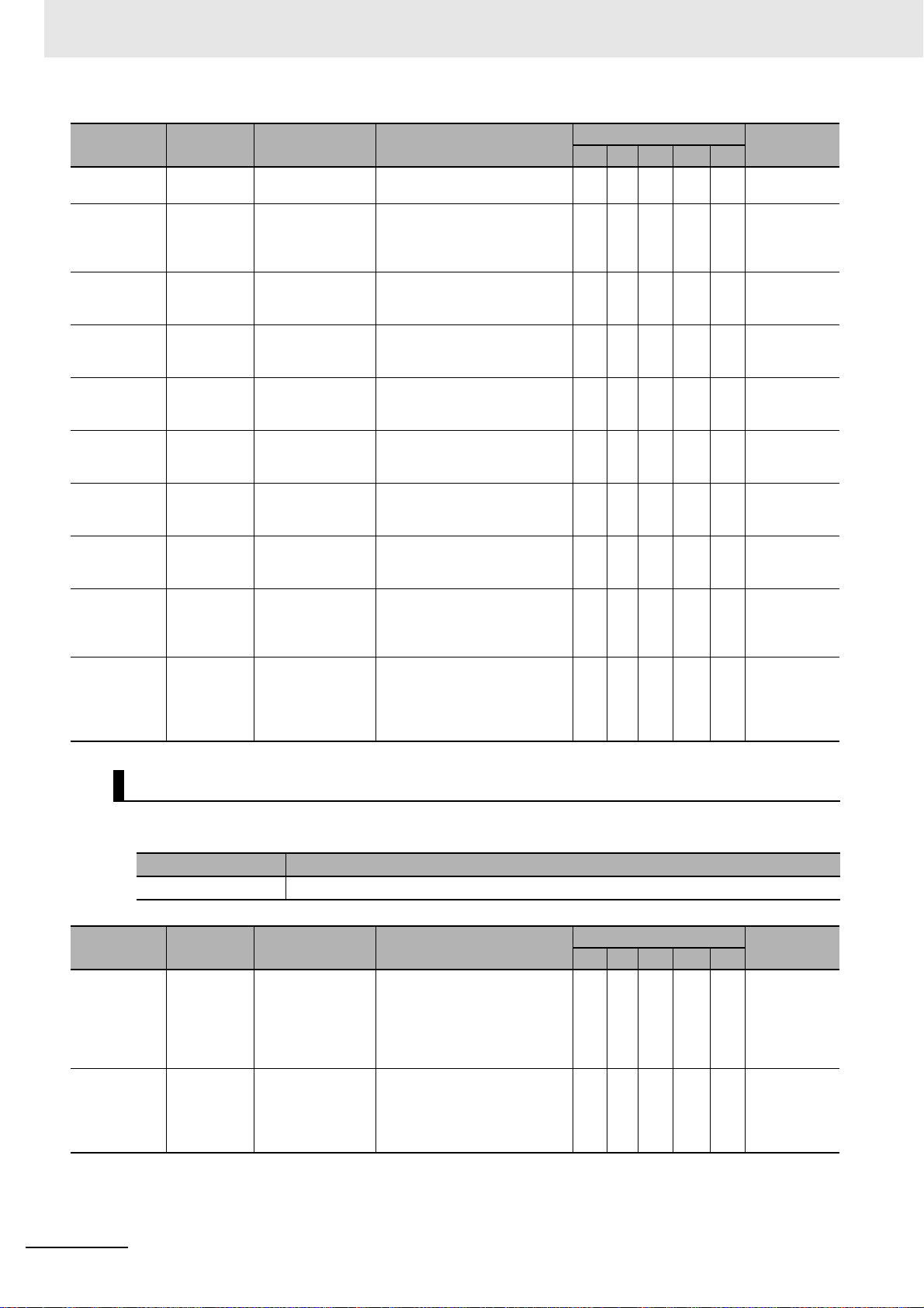
3 Error Tables
Event code Event name Meaning Assumed cause
90150000 hex Reset Exe-
90160000 hex User Pro-
90180000 hex All Controller
90190000 hex Forced
901A0000 hex
(Ver. 1.03 or
later)
901B0000 hex
(Ver. 1.03 or
later)
901C0000 hex
(Ver. 1.03 or
later)
901D0000 hex
(Ver. 1.03 or
later)
90200000 hex
(Ver. 1.11 or
later)
10000 hex
902
(Ver. 1.11 or
later)
cuted
gram Execution ID Write
Errors
Cleared
Refreshing
Cleared
Backup
Started
Backup Completed
Restore
Operation
Started
Restore
Operation
Completed
SD Memory
Card Program Transfer Started
SD Memory
Card Program Transfer
Completed
A reset was executed.
The user program
execution ID was
set or changed in
the CPU Unit.
All current errors
were cleared.
Clearing a forced
refreshing value
was specified.
A backup operation
was started.
The backup operation ended normally.
A restore operation
started.
The restore operation ended normally.
Transferring the SD
Memory Card programs was started.
Transferring the SD
Memory Card programs was completed.
• A reset command was
received.
• A user with Administrator rights
changed the user program execution ID that is set in the CPU
Unit.
• The user cleared all current
errors.
• Clearing a forced refreshing
value was specified by the user.
• A backup operation was
started.
• The backup operation ended
normally.
• A restore operation started. S W500, W501,
• The restore operation ended
normally.
• Transferring the SD Memory
Card programs was started.
• Transferring the SD Memory
Card programs was completed.
Level
Maj Prt Min Obs Info
S W500, W501,
S W500, W501,
S W500, W501,
S W500, W501,
S W500, W501,
S W500, W501,
S W500, W501,
S W500, W501,
S W500, W501,
Reference
W535, W578
W535, W578
W535, W578
W535, W578
W535, W578
W535, W578
W535, W578
W535, W578
35, W578
W5
W535, W578
Errors Related to FINS Communications
The manual names are given below for the catalog numbers given in the Reference column of the
event table.
Cat. No. Manual name
W501 NJ/NX-series CPU Unit Software User's Manual
Event code Event name Meaning Assumed cause
14010000 hex CPU Bus
Unit Setup
Area Error
34100000 hex IP Address
Table Setting
Error
An error was
detected in the
memory check of
the Setup Area for
CPU Bus Units.
The IP address
table settings are
incorrect.
• The power supply to the Controller was interrupted or communications with the Sysmac
Studio were disconnected while
downloading the CPU Bus Unit
Settings.
• The IP address conversion
method is set to the combined
method or the IP address table
method, but the IP address
table settings are incorrect.
Level
Maj Prt Min Obs Info
SW501
SW501
Reference
3-22
NJ/NX-series Troubleshooting Manual (W503)
 Loading...