

Page 1

Machine Automation Controller
NJ-series
Instructions Reference Manual
NJ501-1300
NJ501-1400
NJ501-1500
W502-E1-01
Page 2

OMRON, 2011
All rights reserved. No part of this publication may be reproduced, stored in a retrieval system, or transmitted, in any form, or
by any means, mechanical, electronic, photocopying, recording, or otherwise, without the prior written permission of
OMRON.
No patent liability is assumed with respect to the use of the information contained herein. Moreover, because OMRON is
constantly striving to improve its high-quality products, the information contained in this manual is subject to change without
notice. Every precaution has been taken in the preparation of this manual. Nevertheless, OMRON assumes no responsibility
for errors or omissions. Neither is any liability assumed for damages resulting from the use of the information contained in
this publication.
Page 3

Introduction
Thank you for purchasing an NJ-series CPU Unit.
This manual contains information that is necessary to use the NJ-series CPU Unit. Please read this
manual and make sure you understand the functionality and performance of the NJ-series CPU Unit
before you attempt to use it in a control system.
Keep this manual in a safe place where it will be available for reference during operation.
Intended Audience
This manual is intended for the following personnel, who must also have knowledge of electrical systems (an electrical engineer or the equivalent).
• Personnel in charge of introducing FA systems.
• Personnel in charge of designing FA systems.
• Personnel in charge of installing and maintaining FA systems.
• Personnel in charge of managing FA systems and facilities.
For programming, this manual is intended for personnel who understand the programming language
specifications in international standard IEC 61131-3 or Japanese standard JIS B3503.
Introduction
Applicable Products
This manual covers the following products.
• NJ-series CPU Units
• NJ501-1300
• NJ501-1400
• NJ501-1500
NJ-series Instructions Reference Manual (W502)
1
Page 4
Relevant Manuals
Relevant Manuals
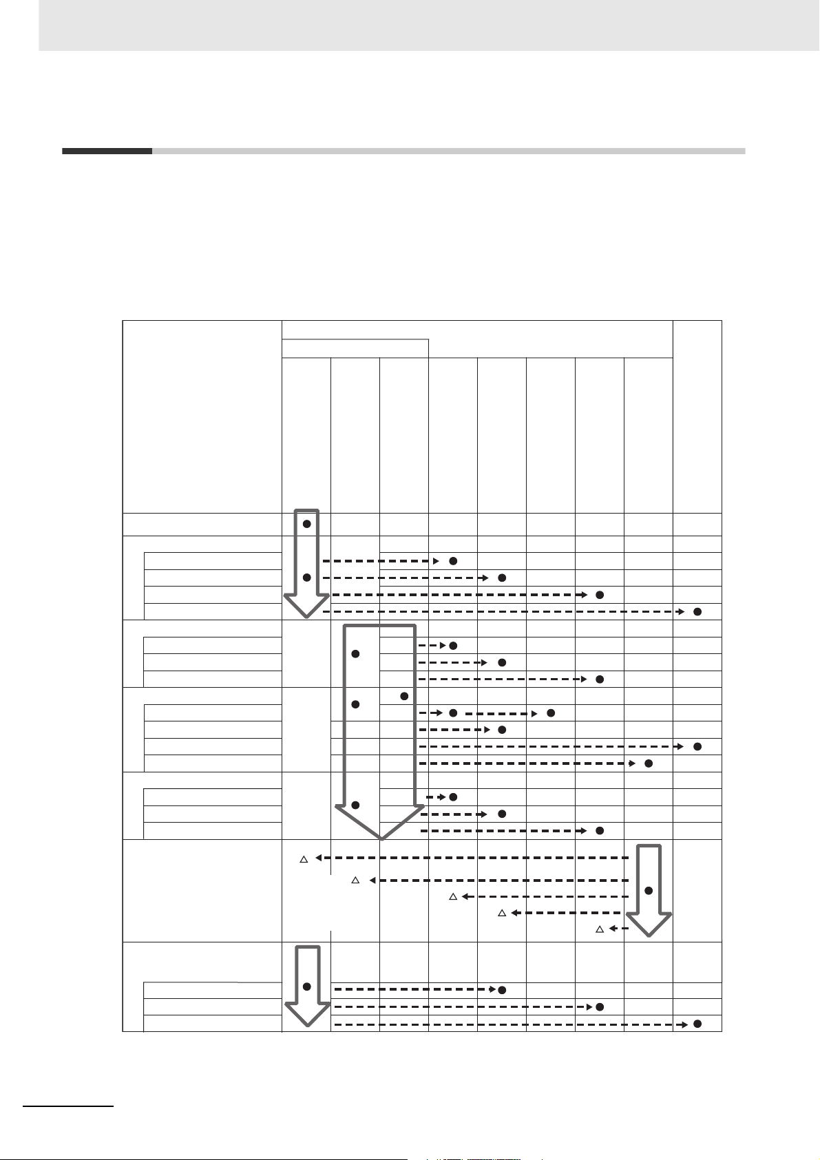
There are three manuals that provide basic information on the NJ-series CPU Units: the NJ-series CPU
Unit Hardware User’s Manual, the NJ-series CPU Unit Software User’s Manual (this manual), and the
NJ-series Instructions Reference Manual.
Most operations are performed from the Sysmac Studio Automation Software. Refer to the Sysmac Studio Version 1 Operation Manual (Cat. No. W504) for information on the Sysmac Studio.
Other manuals are necessary for specific system configurations and applications.
Read all of the manuals that are relevant to your system configuration and application to make the most
of the NJ-series CPU Unit.
Basic information
NJ-series User’s Manuals
Introduction to NJ-series Controllers
Setting devices and hardware
Using motion control
Using EtherCAT
Using EtherNet/IP
Using CJ-series Units
Software settings
Using motion control
Using EtherCAT
Using EtherNet/IP
Programming
Using motion control
Using EtherCAT
Using CJ-series Units
Programming error processing
Testing operation and debugging
Using motion control
Using EtherCAT
Using EtherNet/IP
Troubleshooting and managing
errors in an NJ-series Controller
NJ-series CPU Unit
Hardware User´s Manual
Use the
relevant
manuals for
references
according to
any error that
occurs.
NJ-series CPU Unit
Software User´s Manual
NJ-series Instructions
Reference Manual
NJ-series CPU Unit Motion
Control User´s Manual
NJ-series CPU Unit Built-in
NJ-series Motion Control
EtherCAT Port User´s Manual
Instructions Reference Manual
NJ-series CPU Unit Built-in
EtherNet/IP Port User´s Manual
NJ-series Troubleshooting Manual
CJ-series Special Unit Operation
Manuals for NJ-series CPU Unit
Maintenance
Using EtherCAT
Using EtherNet/IP
Using CJ-series Units
2
NJ-series Instructions Reference Manual (W502)
Page 5

Manual Configuration
NJ-series CPU Unit Hardware User’s Manual (Cat. No. W500)
Section Description
Section 1
Introduction
Section 2
System Configuration
Section 3
Configuration Units
Section 4
Installation and Wiring
Section 5
Troubleshooting
Section 6
Inspection and Maintenance
Appendices
This section provides an introduction to the NJ-series Controllers and their features,
and gives the NJ-series Controller specifications.
This section describes the system configuration used for NJ-series Controllers.
This section describes the parts and functions of the configuration devices in the NJseries Controller configuration, including the CPU Unit and Configuration Units.
This section describes where and how to install the CPU Unit and Configuration Units
and how to wire them.
This section describes the event codes, error confirmation methods, and corrections
for errors that can occur.
This section describes the contents of periodic inspections, the service life of the Battery and Power Supply Units, and replacement methods for the Battery and Power
Supply Units.
The appendices provide the specifications of the Basic I/O Units, Unit dimensions,
load short-circuit protection detection, line disconnection detection, and measures for
EMC Directives.
Manual Configuration
NJ-series CPU Unit Software User’s Manual (Cat. No. W501)
Section Description
Section 1
Introduction
Section 2
CPU Unit Operation
Section 3
I/O Ports, Slave Configuration, and
Unit Configuration
Section 4
Controller Setup
Section 5
Designing Tasks
Section 6
Programming
Section 7
Simulation, Transferring Projects to
the Physical CPU Unit, and Operation
Section 8
CPU Unit Status
Section 9
CPU Unit Functions
Section 10
Communications Setup
Section 11
Example of Actual Application Procedures
Section 12
Troubleshooting
Appendices
This section provides an introduction to the NJ-series Controllers and their features,
and gives the NJ-series Controller specifications.
This section describes the variables and control systems of the CPU Unit and CPU
Unit status.
This section describes how to use I/O ports, how to create the slave configuration
and unit configuration and how to assign functions.
This section describes the initial settings of the function modules.
This section describes the task system and types of tasks.
This section describes programming, including the programming languages and the
variables and instructions that are used in programming.
This section describes simulation of Controller operation and how to use the results
of simulation.
This section describes CPU Unit status.
This section describes the functionality provided by the CPU Unit.
This section describes how to go online with the CPU Unit and how to connect to
other devices.
This section describes the procedures that are used to actually operate an NJ-series
Controller.
This section describes the event codes, error confirmation methods, and corrections
for errors that can occur.
The appendices provide the CPU Unit specifications, task execution times, systemdefined variable lists, data attribute lists, CJ-series Unit memory information, CJseries Unit memory allocation methods, and data type conversion information.
NJ-series Instructions Reference Manual (W502)
3
Page 6

Manual Configuration
NJ-series Instructions Reference Manual (Cat. No. W502)
(This Manual)
Section Description
Section 1
Instruction Set
Section 2
Instruction Descriptions
Appendices
This section provides a table of the instructions that are described in this manual.
This section describes instruction specifications in detail.
The appendices provide a table of error codes and other supplemental information to
use instructions.
4
NJ-series Instructions Reference Manual (W502)
Page 7

Sections in this Manual
Sections in this Manual
1
2
1
2
A
I
Instruction Set
A
Instruction Descriptions
I
Appendices
Index
NJ-series Instructions Reference Manual (W502)
5
Page 8

Sections in this Manual
6
NJ-series Instructions Reference Manual (W502)
Page 9

CONTENTS
Introduction............................................................................................................... 1
Relevant Manuals...................................................................................................... 2
Manual Configuration............................................................................................... 3
Sections in this Manual............................................................................................ 5
Read and Understand this Manual........................................................................ 15
Safety Precautions ................................................................................................. 19
Precautions for Safe Use ....................................................................................... 20
Precautions for Correct Use .................................................................................. 21
CONTENTS
Regulations and Standards ................................................................................... 22
Unit Versions ........................................................................................................... 24
Related Manuals ..................................................................................................... 27
Revision History ..................................................................................................... 29
Section 1 Instruction Set
Instruction Set ........................................................................................................... 1-2
Section 2 Instruction Descriptions
Using this Section ...................................................................................................... 2-2
Ladder Diagram Instructions . . . . . . . . . . . . . . . . . . . . . . . . . . . . . . . . . . . 2-13
LD and LDN ............................................................................................................. 2-14
AND and ANDN ....................................................................................................... 2-16
OR and ORN ........................................................................................................... 2-18
Out and OutNot ....................................................................................................... 2-20
ST Statement Instructions . . . . . . . . . . . . . . . . . . . . . . . . . . . . . . . . . . . . 2-23
IF .............................................................................................................................2-24
CASE ....................................................................................................................... 2-28
WHILE ..................................................................................................................... 2-32
REPEAT .................................................................................................................. 2-34
RETURN ................................................................................................................. 2-36
FOR ......................................................................................................................... 2-37
EXIT ........................................................................................................................ 2-38
Sequence Input Instructions . . . . . . . . . . . . . . . . . . . . . . . . . . . . . . . . . . . 2-39
R_TRIG (Up) and F_TRIG (Down) .......................................................................... 2-40
TestABit and TestABitN ........................................................................................... 2-43
Sequence Output Instructions . . . . . . . . . . . . . . . . . . . . . . . . . . . . . . . . . 2-45
RS ........................................................................................................................... 2-46
SR ........................................................................................................................... 2-48
Set and Reset .......................................................................................................... 2-50
SetBits and ResetBits .............................................................................................. 2-53
SetABit and ResetABit ............................................................................................ 2-55
NJ-series Instructions Reference Manual (W502)
7
Page 10

CONTENTS
OutABit .................................................................................................................... 2-57
Sequence Control Instructions . . . . . . . . . . . . . . . . . . . . . . . . . . . . . . . . .2-59
End .......................................................................................................................... 2-60
RETURN ................................................................................................................. 2-61
MC and MCR ........................................................................................................... 2-62
JMP ......................................................................................................................... 2-74
FOR and NEXT ....................................................................................................... 2-76
BREAK .................................................................................................................... 2-81
Comparison Instructions . . . . . . . . . . . . . . . . . . . . . . . . . . . . . . . . . . . . . .2-83
EQ (=) ...................................................................................................................... 2-84
NE (<>) .................................................................................................................... 2-86
LT (<), LE (<=), GT (>), and GE (>=) ...................................................................... 2-88
EQascii .................................................................................................................... 2-91
NEascii .................................................................................................................... 2-93
LTascii, LEascii, GTascii, and GEascii .................................................................... 2-95
Cmp ......................................................................................................................... 2-98
ZoneCmp ............................................................................................................... 2-100
TableCmp .............................................................................................................. 2-102
AryCmpEQ and AryCmpNE .................................................................................. 2-105
AryCmpLT, AryCmpLE, AryCmpGT, and AryCmpGE ........................................... 2-107
AryCmpEQV and AryCmpNEV ............................................................................. 2-110
AryCmpLTV, AryCmpLEV, AryCmpGTV, and AryCmpGEV ................................. 2-112
Timer Instructions . . . . . . . . . . . . . . . . . . . . . . . . . . . . . . . . . . . . . . . . . .2-115
TON ....................................................................................................................... 2-116
TOF ....................................................................................................................... 2-120
TP .......................................................................................................................... 2-123
AccumulationTimer ................................................................................................ 2-126
Timer ..................................................................................................................... 2-129
Counter Instructions . . . . . . . . . . . . . . . . . . . . . . . . . . . . . . . . . . . . . . . .2-133
CTD ....................................................................................................................... 2-134
CTD_** .................................................................................................................. 2-136
CTU ....................................................................................................................... 2-138
CTU_** .................................................................................................................. 2-140
CTUD .................................................................................................................... 2-142
CTUD_** ................................................................................................................ 2-146
Math Instructions . . . . . . . . . . . . . . . . . . . . . . . . . . . . . . . . . . . . . . . . . . .2-151
ADD (+) ................................................................................................................. 2-152
AddOU (+OU) ........................................................................................................ 2-154
SUB (-) .................................................................................................................. 2-156
SubOU (-OU) ......................................................................................................... 2-158
MUL (*) .................................................................................................................. 2-161
MulOU (*OU) ......................................................................................................... 2-163
DIV (/) .................................................................................................................... 2-166
MOD ...................................................................................................................... 2-168
ABS ....................................................................................................................... 2-170
RadToDeg and DegToRad .................................................................................... 2-172
SIN, COS, and TAN .............................................................................................. 2-174
ASIN, ACOS, and ATAN ....................................................................................... 2-177
SQRT .................................................................................................................... 2-180
LN and LOG .......................................................................................................... 2-182
EXP ....................................................................................................................... 2-185
EXPT (**) ............................................................................................................... 2-187
Inc and Dec ........................................................................................................... 2-189
Rand ...................................................................................................................... 2-191
AryAdd ................................................................................................................... 2-193
AryAddV ................................................................................................................ 2-195
ArySub ................................................................................................................... 2-197
ArySubV ................................................................................................................ 2-199
8
NJ-series Instructions Reference Manual (W502)
Page 11

CONTENTS
AryMean ................................................................................................................ 2-201
ArySD .................................................................................................................... 2-203
ModReal ................................................................................................................ 2-205
Fraction ................................................................................................................. 2-207
CheckReal ............................................................................................................. 2-209
BCD Conversion Instructions . . . . . . . . . . . . . . . . . . . . . . . . . . . . . . . . . 2-211
**_BCD_TO_*** ..................................................................................................... 2-212
**_TO_BCD_*** ..................................................................................................... 2-215
BCD_TO_** ........................................................................................................... 2-218
BCDsToBin ............................................................................................................ 2-221
BinToBCDs_** ....................................................................................................... 2-224
AryToBCD ............................................................................................................. 2-227
AryToBin ................................................................................................................ 2-229
Data Type Conversion Instructions . . . . . . . . . . . . . . . . . . . . . . . . . . . . . 2-231
**_TO_*** (Integer-to-Integer Conversion Group) ................................................. 2-232
**_TO_*** (Integer-to-Bit String Conversion Group) .............................................. 2-235
**_TO_*** (Integer-to-Real Number Conversion Group) ....................................... 2-237
**_TO_*** (Bit String-to-Integer Conversion Group) .............................................. 2-239
**_TO_*** (Bit String-to-Bit String Conversion Group) .......................................... 2-242
**_TO_*** (Bit String-to-Real Number Conversion Group) .................................... 2-244
**_TO_*** (Real Number-to-Integer Conversion Group) ....................................... 2-246
**_TO_*** (Real Number-to-Bit String Conversion Group) .................................... 2-249
**_TO_*** (Real Number-to-Real Number Conversion Group) ............................. 2-251
**_TO_STRING (Integer-to-Text String Conversion Group) ................................. 2-253
**_TO_STRING (Bit String-to-Text String Conversion Group) .............................. 2-255
**_TO_STRING (Real Number-to-Text String Conversion Group) ....................... 2-257
RealToFormatString .............................................................................................. 2-259
LrealToFormatString ............................................................................................. 2-264
STRING_TO_** (Text String-to-Integer Conversion Group) ................................. 2-270
STRING_TO_** (Text String-to-Bit String Conversion Group) .............................. 2-272
STRING_TO_** (Text String-to-Real Number Conversion Group) ....................... 2-274
TO_** (Integer Conversion Group) ........................................................................ 2-277
TO_** (Bit String Conversion Group) .................................................................... 2-279
TO_** (Real Number Conversion Group) .............................................................. 2-281
TRUNC, Round, and RoundUp ............................................................................. 2-283
Bit String Processing Instructions . . . . . . . . . . . . . . . . . . . . . . . . . . . . . . 2-285
AND (&), OR, and XOR ......................................................................................... 2-286
XORN .................................................................................................................... 2-289
NOT ....................................................................................................................... 2-291
AryAnd, AryOr, AryXor, and AryXorN .................................................................... 2-293
Selection Instructions . . . . . . . . . . . . . . . . . . . . . . . . . . . . . . . . . . . . . . . 2-297
SEL ........................................................................................................................ 2-298
MUX ...................................................................................................................... 2-300
LIMIT ..................................................................................................................... 2-302
Band ...................................................................................................................... 2-304
Zone ...................................................................................................................... 2-307
MAX and MIN ........................................................................................................ 2-310
AryMax and AryMin ............................................................................................... 2-312
ArySearch .............................................................................................................. 2-314
Data Movement Instructions . . . . . . . . . . . . . . . . . . . . . . . . . . . . . . . . . . 2-317
MOVE .................................................................................................................... 2-318
MoveBit ................................................................................................................. 2-321
MoveDigit .............................................................................................................. 2-323
TransBits ............................................................................................................... 2-325
MemCopy .............................................................................................................. 2-327
SetBlock ................................................................................................................ 2-329
Exchange .............................................................................................................. 2-331
AryExchange ......................................................................................................... 2-333
NJ-series Instructions Reference Manual (W502)
9
Page 12

CONTENTS
AryMove ................................................................................................................ 2-335
Clear ...................................................................................................................... 2-337
Copy**ToNum (Bit String to Signed Integer) ......................................................... 2-339
Copy**To*** (Bit String to Real Number) ............................................................... 2-341
CopyNumTo** (Signed Integer to Bit String) ......................................................... 2-343
CopyNumTo** (Signed Integer to Real Number) .................................................. 2-345
Copy**To*** (Real Number to Bit String) ............................................................... 2-347
Copy**ToNum (Real Number to Signed Integer) .................................................. 2-349
Shift Instructions . . . . . . . . . . . . . . . . . . . . . . . . . . . . . . . . . . . . . . . . . . .2-351
AryShiftReg ........................................................................................................... 2-352
AryShiftRegLR ....................................................................................................... 2-354
ArySHL and ArySHR ............................................................................................. 2-357
SHL and SHR ........................................................................................................ 2-360
NSHLC and NSHRC ............................................................................................. 2-362
ROL and ROR ....................................................................................................... 2-364
Conversion Instructions . . . . . . . . . . . . . . . . . . . . . . . . . . . . . . . . . . . . . .2-367
Swap ..................................................................................................................... 2-368
Neg ........................................................................................................................ 2-369
Decoder ................................................................................................................. 2-371
Encoder ................................................................................................................. 2-374
BitCnt ..................................................................................................................... 2-376
ColmToLine_** ...................................................................................................... 2-377
LineToColm ........................................................................................................... 2-379
Gray ....................................................................................................................... 2-381
PWLApprox ........................................................................................................... 2-384
MovingAverage ..................................................................................................... 2-387
PIDAT .................................................................................................................... 2-393
DispartReal ............................................................................................................ 2-418
UniteReal ............................................................................................................... 2-421
NumToDecString and NumToHexString ............................................................... 2-423
HexStringToNum_** .............................................................................................. 2-426
FixNumToString .................................................................................................... 2-428
StringToFixNum .................................................................................................... 2-430
DtToString ............................................................................................................. 2-433
DateToString ......................................................................................................... 2-435
TodToString ........................................................................................................... 2-436
GrayToBin_** and BinToGray_** .......................................................................... 2-438
StringToAry ........................................................................................................... 2-441
AryToString ........................................................................................................... 2-443
DispartDigit ............................................................................................................ 2-445
UniteDigit_** .......................................................................................................... 2-447
Dispart8Bit ............................................................................................................. 2-449
Unite8Bit_** ........................................................................................................... 2-451
ToAryByte .............................................................................................................. 2-453
AryByteTo .............................................................................................................. 2-458
SizeOfAry .............................................................................................................. 2-463
Stack and Table Instructions . . . . . . . . . . . . . . . . . . . . . . . . . . . . . . . . . .2-465
StackPush ............................................................................................................. 2-466
StackFIFO and StackLIFO .................................................................................... 2-475
StackIns ................................................................................................................. 2-478
StackDel ................................................................................................................ 2-480
RecSearch ............................................................................................................. 2-482
RecRangeSearch .................................................................................................. 2-487
RecSort ................................................................................................................. 2-492
RecNum ................................................................................................................ 2-497
RecMax and RecMin ............................................................................................. 2-499
FCS Instructions . . . . . . . . . . . . . . . . . . . . . . . . . . . . . . . . . . . . . . . . . . .2-503
StringSum .............................................................................................................. 2-504
StringLRC .............................................................................................................. 2-506
10
NJ-series Instructions Reference Manual (W502)
Page 13

CONTENTS
StringCRCCCITT ................................................................................................... 2-508
StringCRC16 ......................................................................................................... 2-510
AryLRC_** ............................................................................................................. 2-512
AryCRCCCITT ....................................................................................................... 2-514
AryCRC16 ............................................................................................................. 2-516
Text String Instructions . . . . . . . . . . . . . . . . . . . . . . . . . . . . . . . . . . . . . . 2-519
CONCAT ............................................................................................................... 2-520
LEFT and RIGHT .................................................................................................. 2-522
MID ........................................................................................................................ 2-524
FIND ...................................................................................................................... 2-526
LEN ....................................................................................................................... 2-528
REPLACE .............................................................................................................. 2-529
DELETE ................................................................................................................ 2-531
INSERT ................................................................................................................. 2-533
GetByteLen ........................................................................................................... 2-535
ClearString ............................................................................................................ 2-537
ToUCase and ToLCase ......................................................................................... 2-538
TrimL and TrimR ................................................................................................... 2-540
Time and Time of Day Instructions . . . . . . . . . . . . . . . . . . . . . . . . . . . . . 2-543
ADD_TIME ............................................................................................................ 2-544
ADD_TOD_TIME ................................................................................................... 2-546
ADD_DT_TIME ..................................................................................................... 2-548
SUB_TIME ............................................................................................................ 2-550
SUB_TOD_TIME ................................................................................................... 2-552
SUB_TOD_TOD .................................................................................................... 2-554
SUB_DATE_DATE ................................................................................................ 2-555
SUB_DT_DT ......................................................................................................... 2-556
SUB_DT_TIME ...................................................................................................... 2-558
MULTIME .............................................................................................................. 2-560
DIVTIME ................................................................................................................ 2-562
CONCAT_DATE_TOD .......................................................................................... 2-564
DT_TO_TOD ......................................................................................................... 2-566
DT_TO_DATE ....................................................................................................... 2-568
SetTime ................................................................................................................. 2-570
GetTime ................................................................................................................. 2-572
DtToSec ................................................................................................................ 2-574
DateToSec ............................................................................................................ 2-576
TodToSec .............................................................................................................. 2-577
SecToDt ................................................................................................................ 2-578
SecToDate ............................................................................................................ 2-580
SecToTod .............................................................................................................. 2-582
TimeToNanoSec ................................................................................................... 2-583
TimeToSec ............................................................................................................ 2-584
NanoSecToTime ................................................................................................... 2-585
SecToTime ............................................................................................................ 2-586
ChkLeapYear ........................................................................................................ 2-588
GetDaysOfMonth ................................................................................................... 2-589
DaysToMonth ........................................................................................................ 2-591
GetDayOfWeek ..................................................................................................... 2-593
GetWeekOfYear .................................................................................................... 2-595
DtToDateStruct ...................................................................................................... 2-597
DateStructToDt ...................................................................................................... 2-599
System Control Instructions . . . . . . . . . . . . . . . . . . . . . . . . . . . . . . . . . . 2-601
TraceSamp ............................................................................................................ 2-602
TraceTrig ............................................................................................................... 2-605
GetTraceStatus ..................................................................................................... 2-607
SetAlarm ................................................................................................................ 2-610
ResetAlarm ............................................................................................................ 2-615
GetAlarm ............................................................................................................... 2-617
NJ-series Instructions Reference Manual (W502)
11
Page 14

CONTENTS
ResetPLCError ...................................................................................................... 2-619
GetPLCError .......................................................................................................... 2-622
ResetCJBError ...................................................................................................... 2-624
GetCJBError .......................................................................................................... 2-626
GetEIPError ........................................................................................................... 2-628
ResetMCError ....................................................................................................... 2-630
GetMCError ........................................................................................................... 2-634
ResetECError ........................................................................................................ 2-636
GetECError ............................................................................................................ 2-637
SetInfo ................................................................................................................... 2-639
ResetUnit ............................................................................................................... 2-641
GetNTPStatus ....................................................................................................... 2-645
Communications Instructions . . . . . . . . . . . . . . . . . . . . . . . . . . . . . . . . .2-647
ExecPMCR ............................................................................................................ 2-648
SerialSend ............................................................................................................. 2-658
SerialRcv ............................................................................................................... 2-665
SendCmd .............................................................................................................. 2-674
CIPOpen ................................................................................................................ 2-684
CIPRead ................................................................................................................ 2-692
CIPWrite ................................................................................................................ 2-696
CIPSend ................................................................................................................ 2-701
CIPClose ............................................................................................................... 2-704
CIPUCMMRead ..................................................................................................... 2-706
CIPUCMMWrite ..................................................................................................... 2-710
CIPUCMMSend ..................................................................................................... 2-716
EC_CoESDOWrite ................................................................................................ 2-726
EC_CoESDORead ................................................................................................ 2-729
EC_StartMon ......................................................................................................... 2-734
EC_StopMon ......................................................................................................... 2-740
EC_SaveMon ........................................................................................................ 2-742
EC_CopyMon ........................................................................................................ 2-744
EC_DisconnectSlave ............................................................................................. 2-746
EC_ConnectSlave ................................................................................................. 2-752
SktUDPCreate ....................................................................................................... 2-754
SktUDPRcv ........................................................................................................... 2-761
SktUDPSend ......................................................................................................... 2-764
SktTCPAccept ....................................................................................................... 2-767
SktTCPConnect ..................................................................................................... 2-770
SktTCPRcv ............................................................................................................ 2-777
SktTCPSend .......................................................................................................... 2-780
SktGetTCPStatus .................................................................................................. 2-783
SktClose ................................................................................................................ 2-786
SktClearBuf ........................................................................................................... 2-789
SD Memory Card Instructions . . . . . . . . . . . . . . . . . . . . . . . . . . . . . . . . .2-793
FileWriteVar ........................................................................................................... 2-794
FileReadVar .......................................................................................................... 2-799
FileOpen ................................................................................................................ 2-803
FileClose ............................................................................................................... 2-806
FileSeek ................................................................................................................ 2-809
FileRead ................................................................................................................ 2-812
FileWrite ................................................................................................................ 2-819
FileGets ................................................................................................................. 2-826
FilePuts ................................................................................................................. 2-833
FileCopy ................................................................................................................ 2-840
FileRemove ........................................................................................................... 2-848
FileRename ........................................................................................................... 2-852
DirCreate ............................................................................................................... 2-857
DirRemove ............................................................................................................ 2-860
12
NJ-series Instructions Reference Manual (W502)
Page 15

Appendices
A-1 Error Codes Related to Instructions ......................................................................................A-2
A-2 Error Code Descriptions .......................................................................................................A-18
A-3 Error Code Details .................................................................................................................A-24
A-4 SDO Abort Codes ..................................................................................................................A-47
CONTENTS
Other Instructions . . . . . . . . . . . . . . . . . . . . . . . . . . . . . . . . . . . . . . . . . . 2-863
ReadNbit_** ........................................................................................................... 2-864
WriteNbit_** ........................................................................................................... 2-866
ChkRange ............................................................................................................. 2-868
GetMyTaskStatus .................................................................................................. 2-870
Task_IsActive ........................................................................................................ 2-873
Lock and Unlock .................................................................................................... 2-875
Get**Clk ................................................................................................................. 2-880
Get**Cnt ................................................................................................................ 2-881
Index
NJ-series Instructions Reference Manual (W502)
13
Page 16

CONTENTS
14
NJ-series Instructions Reference Manual (W502)
Page 17

Read and Understand this Manual
Read and Understand this Manual
Please read and understand this manual before using the product. Please consult your OMRON representative
if you have any questions or comments.
Warranty and Limitations of Liability
WARRANTY
OMRON's exclusive warranty is that the products are free from defects in materials and workmanship for a
period of one year (or other period if specified) from date of sale by OMRON.
OMRON MAKES NO WARRANTY OR REPRESENTATION, EXPRESS OR IMPLIED, REGARDING NONINFRINGEMENT, MERCHANTABILITY, OR FITNESS FOR PARTICULAR PURPOSE OF THE
PRODUCTS. ANY BUYER OR USER ACKNOWLEDGES THAT THE BUYER OR USER ALONE HAS
DETERMINED THAT THE PRODUCTS WILL SUITABLY MEET THE REQUIREMENTS OF THEIR
INTENDED USE. OMRON DISCLAIMS ALL OTHER WARRANTIES, EXPRESS OR IMPLIED.
LIMITATIONS OF LIABILITY
OMRON SHALL NOT BE RESPONSIBLE FOR SPECIAL, INDIRECT, OR CONSEQUENTIAL DAMAGES,
LOSS OF PROFITS OR COMMERCIAL LOSS IN ANY WAY CONNECTED WITH THE PRODUCTS,
WHETHER SUCH CLAIM IS BASED ON CONTRACT, WARRANTY, NEGLIGENCE, OR STRICT
LIABILITY.
In no event shall the responsibility of OMRON for any act exceed the individual price of the product on which
liability is asserted.
IN NO EVENT SHALL OMRON BE RESPONSIBLE FOR WARRANTY, REPAIR, OR OTHER CLAIMS
REGARDING THE PRODUCTS UNLESS OMRON'S ANALYSIS CONFIRMS THAT THE PRODUCTS
WERE PROPERLY HANDLED, STORED, INSTALLED, AND MAINTAINED AND NOT SUBJECT TO
CONTAMINATION, ABUSE, MISUSE, OR INAPPROPRIATE MODIFICATION OR REPAIR.
NJ-series Instructions Reference Manual (W502)
15
Page 18

Read and Understand this Manual
Application Considerations
SUITABILITY FOR USE
OMRON shall not be responsible for conformity with any standards, codes, or regulations that apply to the
combination of products in the customer's application or use of the products.
At the customer's request, OMRON will provide applicable third party certification documents identifying
ratings and limitations of use that apply to the products. This information by itself is not sufficient for a
complete determination of the suitability of the products in combination with the end product, machine,
system, or other application or use.
The following are some examples of applications for which particular attention must be given. This is not
intended to be an exhaustive list of all possible uses of the products, nor is it intended to imply that the uses
listed may be suitable for the products:
• Outdoor use, uses involving potential chemical contamination or electrical interference, or conditions or
uses not described in this manual.
• Nuclear energy control systems, combustion systems, railroad systems, aviation systems, medical
equipment, amusement machines, vehicles, safety equipment, and installations subject to separate
industry or government regulations.
• Systems, machines, and equipment that could present a risk to life or property.
Please know and observe all prohibitions of use applicable to the products.
NEVER USE THE PRODUCTS FOR AN APPLICATION INVOLVING SERIOUS RISK TO LIFE OR
PROPERTY WITHOUT ENSURING THAT THE SYSTEM AS A WHOLE HAS BEEN DESIGNED TO
ADDRESS THE RISKS, AND THAT THE OMRON PRODUCTS ARE PROPERLY RATED AND
INSTALLED FOR THE INTENDED USE WITHIN THE OVERALL EQUIPMENT OR SYSTEM.
PROGRAMMABLE PRODUCTS
OMRON shall not be responsible for the user's programming of a programmable product, or any
consequence thereof.
16
NJ-series Instructions Reference Manual (W502)
Page 19

Read and Understand this Manual
Disclaimers
CHANGE IN SPECIFICATIONS
Product specifications and accessories may be changed at any time based on improvements and other
reasons.
It is our practice to change model numbers when published ratings or features are changed, or when
significant construction changes are made. However, some specifications of the products may be changed
without any notice. When in doubt, special model numbers may be assigned to fix or establish key
specifications for your application on your request. Please consult with your OMRON representative at any
time to confirm actual specifications of purchased products.
DIMENSIONS AND WEIGHTS
Dimensions and weights are nominal and are not to be used for manufacturing purposes, even when
tolerances are shown.
PERFORMANCE DATA
Performance data given in this manual is provided as a guide for the user in determining suitability and does
not constitute a warranty. It may represent the result of OMRON's test conditions, and the users must
correlate it to actual application requirements. Actual performance is subject to the OMRON Warranty and
Limitations of Liability.
ERRORS AND OMISSIONS
The information in this manual has been carefully checked and is believed to be accurate; however, no
responsibility is assumed for clerical, typographical, or proofreading errors, or omissions.
NJ-series Instructions Reference Manual (W502)
17
Page 20

Read and Understand this Manual
18
NJ-series Instructions Reference Manual (W502)
Page 21

Safety Precautions
Refer to the following manuals for safety precautions.
• NJ-series CPU Unit Hardware User’s Manual (Cat No. W500)
• NJ-series CPU Unit Software User’s Manual (Cat No. W501)
Safety Precautions
NJ-series Instructions Reference Manual (W502)
19
Page 22

Precautions for Safe Use
Precautions for Safe Use
Refer to the following manuals for precautions for safe use.
• NJ-series CPU Unit Hardware User’s Manual (Cat No. W500)
• NJ-series CPU Unit Software User’s Manual (Cat No. W501)
20
NJ-series Instructions Reference Manual (W502)
Page 23

Precautions for Correct Use
Refer to the following manuals for precautions for correct use.
• NJ-series CPU Unit Hardware User’s Manual (Cat No. W500)
• NJ-series CPU Unit Software User’s Manual (Cat No. W501)
Precautions for Correct Use
NJ-series Instructions Reference Manual (W502)
21
Page 24

Regulations and Standards
Regulations and Standards
Conformance to EC Directives
Applicable Directives
• EMC Directives
• Low Voltage Directive
Concepts
z EMC Directive
OMRON devices that comply with EC Directives also conform to the related EMC standards so that
they can be more easily built into other devices or the overall machine. The actual products have
been checked for conformity to EMC standards.*
Whether the products conform to the standards in the system used by the customer, however, must
be checked by the customer. EMC-related performance of the OMRON devices that comply with EC
Directives will vary depending on the configuration, wiring, and other conditions of the equipment or
control panel on which the OMRON devices are installed. The customer must, therefore, perform the
final check to confirm that devices and the overall machine conform to EMC standards.
* Applicable EMC (Electromagnetic Compatibility) standards are as follows:
EMS (Electromagnetic Susceptibility): EN 61131-2 and EN 61000-6-2
EMI (Electromagnetic Interference): EN 61131-2 and EN 61000-6-4 (Radiated emission: 10-m regulations)
z Low Voltage Directive
Always ensure that devices operating at voltages of 50 to 1,000 VAC and 75 to 1,500 VDC meet the
required safety standards. The applicable directive is EN 61131-2.
z Conformance to EC Directives
The NJ-series Controllers comply with EC Directives. To ensure that the machine or device in which
the NJ-series Controller is used complies with EC Directives, the Controller must be installed as follows:
• The NJ-series Controller must be installed within a control panel.
• You must use reinforced insulation or double insulation for the DC power supplies connected to
DC Power Supply Units and I/O Units.
• NJ-series Controllers that comply with EC Directives also conform to the Common Emission Standard (EN 61000-6-4). Radiated emission characteristics (10-m regulations) may vary depending
on the configuration of the control panel used, other devices connected to the control panel, wiring, and other conditions.
You must therefore confirm that the overall machine or equipment complies with EC Directives.
22
NJ-series Instructions Reference Manual (W502)
Page 25

Conformance to Shipbuilding Standards
The NJ-series Controllers comply with the following shipbuilding standards. Applicability to the shipbuilding standards is based on certain usage conditions. It may not be possible to use the product in
some locations. Contact your OMRON representative before attempting to use a Controller on a
ship.
Usage Conditions for NK and LR Shipbuilding Standards
• The NJ-series Controller must be installed within a control panel.
• Gaps in the door to the control panel must be completely filled or covered with gaskets or other
material.
• The following noise filter must be connected to the power supply line.
Noise Filter
Manufacturer Model
Cosel Co., Ltd. TAH-06-683
Regulations and Standards
Trademarks
• Sysmac and SYSMAC are trademarks or registered trademarks of OMRON Corporation in Japan
and other countries for OMRON factory automation products.
• Windows, Windows 98, Windows XP, Windows Vista, and Windows 7 are registered trademarks of
Microsoft Corporation in the USA and other countries.
•EtherCAT is a registered trademark of Beckhoff Automation GmbH for their patented technology.
• The SD logo is a trademark of SD-3C, LLC.
Other company names and product names in this document are the trademarks or registered trademarks of their respective companies.
Software Licenses and Copyrights
This product incorporates certain third party software. The license and copyright information associated with this software is available at http://www.fa.omron.co.jp/nj_info_e/.
NJ-series Instructions Reference Manual (W502)
23
Page 26
Unit Versions
Unit Versions
Unit Versions
A “unit version” has been introduced to manage CPU Units in the NJ Series according to differences in
functionality accompanying Unit upgrades.
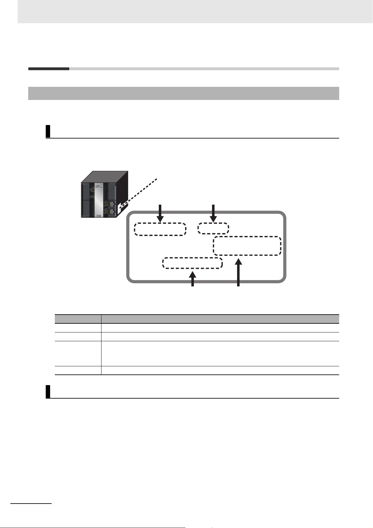
Notation of Unit Versions on Products
The unit version is given on the ID information label of the products for which unit versions are managed, as shown below.
Example for NJ-series NJ501-@@@@ CPU Unit:
ID information label
Unit model
NJ501 -1500 Ver.1.@@
PORT1 MAC ADDRESS: @@@@@@@@@@@@
PORT2 MAC ADDRESS: @@@@@@@@@@@@
Lot No. DDMYY@ xxxx
Unit version
Lot number and serial number MAC address
The following information is provided on the ID information label.
Item Description
Unit model Gives the model of the Unit.
Unit version Gives the unit version of the Unit.
Lot number and
serial number
MAC address Gives the MAC address of the built-in port on the Unit.
Gives the lot number and serial number of the Unit.
DDMYY: Lot number, @: For use by OMRON, xxxx: Serial number
“M” gives the month (1 to 9: January to September, X: October, Y: November, Z: December)
24
Confirming Unit Versions with Sysmac Studio
You can use the Unit Production Information on the Sysmac Studio to check the unit version of the CPU
Unit, CJ-series Special I/O Units, CJ-series CPU Bus Units, and EtherCAT slaves. The unit versions of
CJ-series Basic I/O Units cannot be checked from the Sysmac Studio.
z CPU Unit and CJ-series Units
1 Double-click CPU/Expansion Racks under Configurations and Setup in the Multiview
Explorer. Or, right-click CPU/Expansion Racks under Configurations and Setup and select
Edit from the menu.
The Unit Editor is displayed for the Controller Configurations and Setup layer.
NJ-series Instructions Reference Manual (W502)
Page 27
Unit Versions
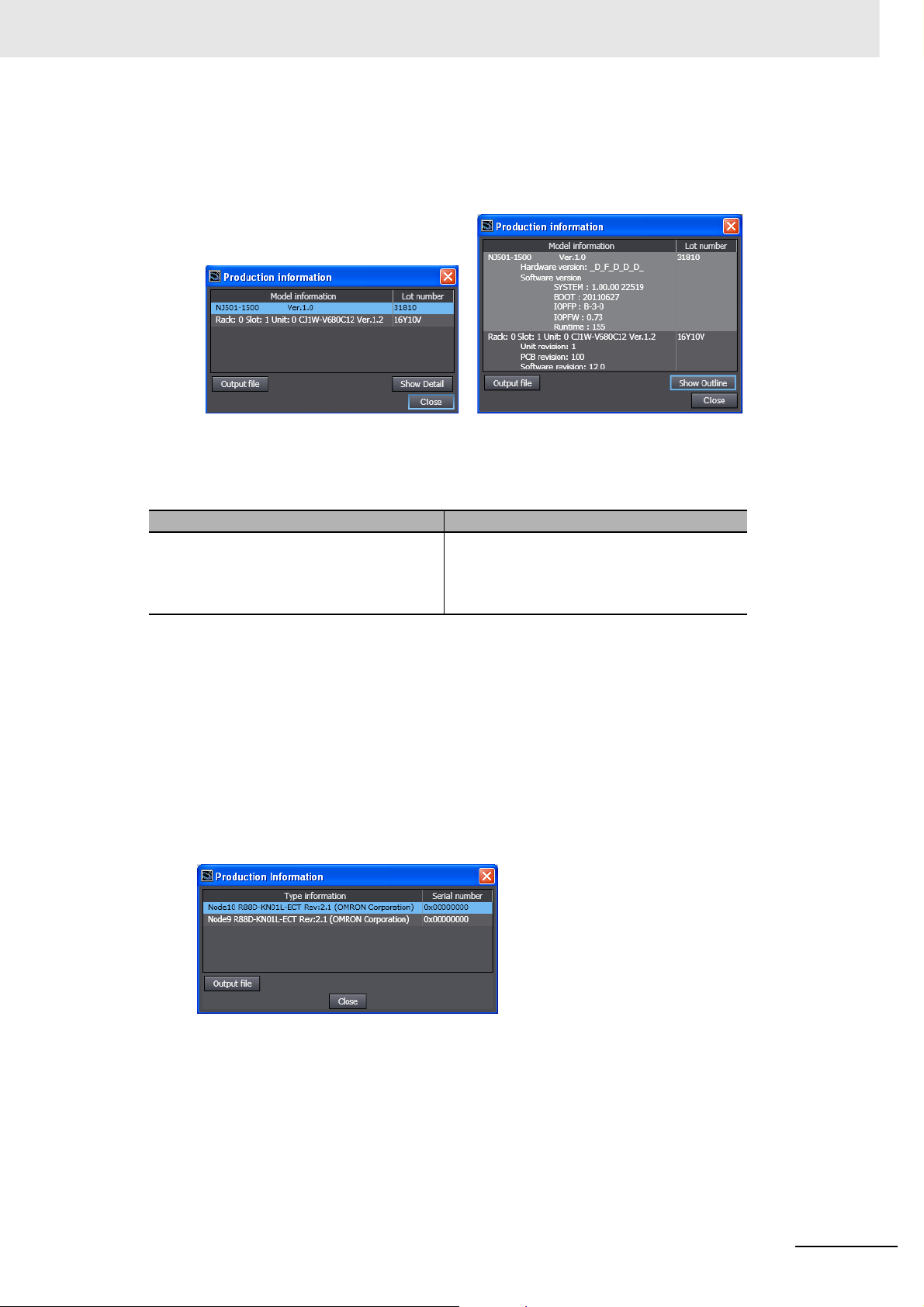
2 Right-click any open space in the Unit Editor and select Production Information.
The Production Information Dialog Box is displayed.
Simple Display Detailed Display
In this example, “Ver.1.0” is displayed next to the unit model.
The following items are displayed.
CPU Unit CJ-series Units
Unit model
Unit version
Lot number
Unit model
Unit version
Lot number
Rack number, slot number, and unit number
z EtherCAT Slaves
1 Double-click EtherCAT under Configurations and Setup in the Multiview Explorer. Or, right-
click EtherCAT under Configurations and Setup and select Edit from the menu.
The EtherCAT Configuration Tab Page is displayed for the Controller Configurations and Setup
layer.
2 Right-click the master in the EtherCAT Configurations Editing Pane and select Display Produc-
tion Information.
The Production Information Dialog Box is displayed.
The following items are displayed.
Node address
Type information*
Serial number
* If the model number cannot be determined (such as when there is no ESI file), the vendor ID, product
code, and revision number are displayed.
NJ-series Instructions Reference Manual (W502)
25
Page 28

Unit Versions
Unit Version Notation
In this manual, unit versions are specified as shown in the following table.
Product nameplate Notation in this manual Remarks
“Ver.1.0” or later to the right of
the lot number
Unit version 1.0 or later Unless unit versions are specified, the information in this manual
applies to all unit versions.
26
NJ-series Instructions Reference Manual (W502)
Page 29

Related Manuals
The following manuals are related to the NJ-series Controllers. Use these manuals for reference.
Manual name Cat. No. Model numbers Application Description
NJ-series CPU Unit
Hardware User’s Manual
NJ-series CPU Unit Software User’s Manual
NJ-series CPU Unit
Motion Control User’s
Manual
NJ-series Instructions
Reference Manual
NJ-series Motion Control
Instructions Reference
Manual
CJ-series Special Unit
Manuals for NJ-series
CPU Unit
W500 NJ501-@@@@ Learning the basic specifi-
cations of the NJ-series
CPU Units, including introductory information,
designing, installation, and
maintenance. Mainly hardware information is provided.
W501 NJ501-@@@@ Learning how to program
and set up an NJ-series
CPU Unit. Mainly software
information is provided.
W507 NJ501-@@@@ Learning about motion
control settings and programming concepts.
W502 NJ501-@@@@ Learning about the specifi-
W508 NJ501-@@@@ Learning about the specifi-
W490
W498
W499
W491
Z317
W492
W494
W497
CJ1W-@@@@ Learning how to use CJ-
cations of the instruction
set that is provided by
OMRON.
cations of the motion control instructions that are
provided by OMRON.
series Units with an NJseries CPU Unit.
An introduction to the entire NJ-series system is
provided along with the following information on
a Controller built with an NJ501 CPU Unit.
• Features and system configuration
• Introduction
• Part names and functions
• General specifications
• Installation and wiring
• Maintenance and inspection
Use this manual together with the NJ-series
CPU Unit Software User’s Manual (Cat. No.
W501).
The following information is provided on a Controller built with an NJ501 CPU Unit.
• CPU Unit operation
• CPU Unit features
• Initial settings
• Programming based on IEC 61131-3 language specifications
Use this manual together with the NJ-series
CPU Unit Hardware User’s Manual (Cat. No.
W500).
The settings and operation of the CPU Unit and
programming concepts for motion control are
described. Use this manual together with the
NJ-series CPU Unit Hardware User’s Manual
(Cat. No. W500) and NJ-series CPU Unit Soft-
ware User’s Manual (Cat. No. W501).
The instructions in the instruction set (IEC
61131-3 specifications) are described. When
programming, use this manual together with the
NJ-series CPU Unit Hardware User’s Manual
(Cat. No. W500) and NJ-series CPU Unit Software User’s Manual (Cat. No. W501).
The motion control instructions are described.
When programming, use this manual together
with the NJ-series CPU Unit Hardware User’s
Manual (Cat. No. W500), NJ-series CPU Unit
Software User’s Manual (Cat. No. W501) and
NJ-series CPU Unit Motion Control User’s Manual (Cat. No. W507).
The methods and precautions for using CJseries Units with an NJ501 CPU Unit are
described, including access methods and programming interfaces. Manuals are available for
the following Units.
Analog I/O Units, Insulated-type Analog I/O
Units, Temperature Control Units, ID Sensor
Units, High-speed Counter Units, Serial Communications Units, and DeviceNet Units.
Use these manuals together with the NJ-series
CPU Unit Hardware User’s Manual (Cat. No.
W500) and NJ-series CPU Unit Software User’s
Manual (Cat. No. W501).
Related Manuals
NJ-series Instructions Reference Manual (W502)
27
Page 30

Related Manuals
Manual name Cat. No. Model numbers Application Description
NJ-series CPU Unit Builtin EtherCAT Port User’s
Manual
NJ-series CPU Unit Builtin EtherNet/IP Port
User’s Manual
NJ-series Troubleshooting Manual
Sysmac Studio Version 1
Operation Manual
CX-Integrator
CS/CJ/CP/NSJ-series
Network Configuration
Tool Operation Manual
CX-Designer User’s
Manual
CX-Protocol Operation
Manual
W505 NJ501-@@@@ Using the built-in EtherCAT
port on an NJ-series CPU
Unit.
W506 NJ501-@@@@ Using the built-in Ether-
Net/IP port on an NJ-series
CPU Unit.
W503 NJ501-@@@@ Learning about the errors
that may be detected in an
NJ-series Controller.
W504 SYSMAC-
SE2@@@
W464 Learning how to configure
V099 Learning to create screen
W344 Creating data transfer pro-
Learning about the operating procedures and functions of the Sysmac Studio.
networks (data links, routing tables, Communications Unit settings, etc.).
data for NS-series Programmable Terminals.
tocols for general-purpose
devices connected to CJseries Serial Communications Units.
Information on the built-in EtherCAT port is provided. This manual provides an introduction and
provides information on the configuration, features, and setup.
Use this manual together with the NJ-series
CPU Unit Hardware User’s Manual (Cat. No.
W500) and NJ-series CPU Unit Software User’s
Manual (Cat. No. W501).
Information on the built-in EtherNet/IP port is
provided. Information is provided on the basic
setup, tag data links, and other features.
Use this manual together with the NJ-series
CPU Unit Hardware User’s Manual (Cat. No.
W500) and NJ-series CPU Unit Software User’s
Manual (Cat. No. W501).
Concepts on managing errors that may be
detected in an NJ-series Controller and information on individual errors are described.
Use this manual together with the NJ-series
CPU Unit Hardware User’s Manual (Cat. No.
W500) and NJ-series CPU Unit Software User’s
Manual (Cat. No. W501).
Describes the operating procedures of the Sysmac Studio.
Describes operating procedures for the CX-Integrator.
Describes operating procedures for the CXDesigner.
Describes operating procedures for the CX-Protocol.
28
NJ-series Instructions Reference Manual (W502)
Page 31

Revision History
A manual revision code appears as a suffix to the catalog number on the front and back covers of the
manual.
Revision History
Cat. No.
Revision code Date Revised content
01 July 2011 Original production
W502-E1-01
Revision code
NJ-series Instructions Reference Manual (W502)
29
Page 32

Revision History
30
NJ-series Instructions Reference Manual (W502)
Page 33

Instruction Set
This section provides a table of the instructions that you can use with NJ-series Controllers.
Instruction Set . . . . . . . . . . . . . . . . . . . . . . . . . . . . . . . . . . . . . . . . . . . . . . . . 1-2
1
NJ-series Instructions Reference Manual (W502)
1-1
Page 34

1 Instruction Set
Instruction Set
Typ e Instruction Name Function Page
Ladder Diagram
Instructions
ST Statement
Instructions
Sequence Input
Instructions
Sequence Output Instructions
LD Load Reads the value of a BOOL variable. 2-14
LDN Load NOT Reads the inverse of the value of a BOOL vari-
able.
AND AND Takes the logical AND of the value of a BOOL
variable and the input value.
ANDN AND NOT Takes the logical AND of the inverse of the
value of a BOOL variable and the input value.
OR OR Takes the logical OR of the value of a BOOL
variable and the execution condition.
ORN OR NOT Takes the logical OR of the inverse of the value
of a BOOL variable and the execution condition.
Out Output Takes the logical result from the previous
instruction and outputs it to a BOOL variable.
OutNot Output NOT Takes the inverse of the logical result from the
previous instruction and outputs it to a BOOL
variable.
IF If Uses the evaluation result of a specified condi-
tion expression to select one of two statements
to execute.
CASE Case Selects the statement to execute based on the
value of a specified integer expression.
WHILE While Repeatedly executes a statement as long as
the evaluation result of a specified condition
expression is TRUE.
REPEAT Repeat Executes a statement once and then executes
it repeatedly until a specified condition expression is TRUE.
RETURN Return Ends a function or function block and returns
processing to the calling instruction.
FOR Repeat Start Marks the starting position for repeat process-
ing of statements between the FOR and
END_FOR statements and specifies the
repeat condition.
EXIT Break Loop Cancels repeat processing from the lowest
level FOR statement to the END_FOR statement.
R_TRIG (Up) Up Trigger Outputs TRUE for one task period only when
the input signal changes to TRUE.
F_TRIG (Down) Down Trigger Outputs TRUE for one task period only when
the input signal changes to FALSE.
TestABit Test A Bit Outputs the value of the specified bit in a bit
string.
TestABitN Test A Bit NOT Outputs the inverse of the value of the speci-
fied bit in a bit string.
RS Reset-Priority
Keep
Retains the value of a BOOL variable. It gives
priority to the Reset input if both the Set input
and Reset input are TRUE.
2-14
2-16
2-16
2-18
2-18
2-20
2-20
2-24
2-28
2-32
2-34
2-36
2-37
2-38
2-40
2-40
2-43
2-43
2-46
1-2
NJ-series Instructions Reference Manual (W502)
Page 35

1 Instruction Set
Type Instruction Name Function Page
Sequence Output Instructions
Sequence Control Instructions
Comparison
Instructions
SR Set-Priority Keep Retains the value of a BOOL variable. It gives
priority to the Set input if both the Set input and
Reset input are TRUE.
Set Set Changes a BOOL variable to TRUE. 2-50
Reset Reset Changes a BOOL variable to FALSE. 2-50
SetBits Set Bits Changes consecutive bits in bit string data to
TRUE.
ResetBits Reset Bits Changes consecutive bits in bit string data to
FALSE.
SetABit Set A Bit Changes the specified bit in bit string data to
TRUE.
ResetABit Reset A Bit Changes the specified bit in bit string data to
FALSE.
OutABit Output A Bit Changes the specified bit in bit string data to
TRUE or FALSE.
End End Ends execution of a program in the current
task period.
RETURN Return Ends a function or function block and returns
processing to the calling instruction.
MC Master Control
Start
MCR Master Control End Marks the end point of a master control region. 2-62
JMP Jump Moves processing to the specified jump desti-
FOR Repeat Start Marks the starting position for repeat process-
NEXT Repeat End Marks the ending position for repeat process-
BREAK Break Loop Cancels repeat processing from the lowest
EQ (=) Equal Determines if two or more values or text strings
NE (<>) Not Equal Determines if two values or text strings are not
LT (<) Less Than Performs a less than comparison between val-
LE (<=) Less Than Or
Equal
GT (>) Greater Than Performs a greater than comparison between
GE (>=) Greater Than Or
Equal
EQascii Text String
Comparison Equal
NEascii Text String
Comparison Not
Equal
LTascii Text String
Comparison Less
Than
LEascii Text String
Comparison Less
Than or Equal
Marks the starting point of a master control
region and resets the master control region.
nation.
ing and specifies the repeat condition.
ing.
level FOR instruction to the NEXT instruction.
are all equivalent.
equivalent.
ues.
Performs a less than or equal comparison
between values.
values.
Performs a greater than or equal comparison
between values.
Determines if two or more text strings are all
equivalent.
Determines if two text strings are not equivalent.
Performs a less than comparison between text
strings.
Performs a less than or equal comparison
between text strings.
2-48
2-53
2-53
2-55
2-55
2-57
2-60
2-61
2-62
2-74
2-76
2-76
2-81
2-84
2-86
2-88
2-88
2-88
2-88
2-91
2-93
2-95
2-95
Instruction Set
1
NJ-series Instructions Reference Manual (W502)
1-3
Page 36

1 Instruction Set
Typ e Instruction Name Function Page
Comparison
Instructions
Timer Instructions
GTascii Text String
Comparison
Greater Than
GEascii Text String
Comparison
Greater Than or
Equal
Cmp Compare Compares two values. 2-98
ZoneCmp Zone Comparison Determines if the comparison data is within the
TableCmp Table Comparison Compares the comparison data with multiple
AryCmpEQ Array Comparison
Equal
AryCmpNE Array Comparison
Not Equal
AryCmpLT Array Comparison
Less Than
AryCmpLE Array Comparison
Less Than Or
Equal
AryCmpGT Array Comparison
Greater Than
AryCmpGE Array Comparison
Greater Than Or
Equal
AryCmpEQV Array Value
Comparison Equal
AryCmpNEV Array Value
Comparison Not
Equal
AryCmpLTV Array Value
Comparison Less
Than
AryCmpLEV Array Value
Comparison Less
Than Or Equal
AryCmpGTV Array Value
Comparison
Greater Than
AryCmpGEV Array Value
Comparison
Greater Than Or
Equal
TON On-Delay Timer Outputs TRUE when the set time elapses after
TOF Off-Delay Timer Outputs FALSE when the set time elapses
TP Timer Pulse Outputs TRUE while the set time elapses after
AccumulationTimer Accumulation
Timer
Timer Hundred-ms Timer Outputs TRUE when the set time elapses after
Performs a greater than comparison between
text strings.
Performs a greater than or equal comparison
between text strings.
specified maximum and minimum values.
defined ranges in a comparison table.
Determines if the corresponding elements of
two arrays are equal.
Determines if the corresponding elements of
two arrays are not equal.
Performs a less than comparison between the
corresponding elements of two arrays.
Performs a less than or equal comparison
between the corresponding elements of two
arrays.
Performs a greater than comparison between
the corresponding elements of two arrays.
Performs a greater than or equal comparison
between the corresponding elements of two
arrays.
Determines if the elements of an array are
equal to a value.
Determines if the elements of an array are not
equal to a value.
Performs a less than comparison between a
value and the elements of an array.
Performs a less than or equal comparison
between a value and the elements of an array.
Performs a greater than comparison between a
value and the elements of an array.
Performs a greater than or equal comparison
between a value and the elements of an array.
the timer starts.
after the timer starts.
the timer starts.
Totals the time that the timer input is TRUE. 2-126
the timer starts. Set the time in increments of
100 ms. The timing accuracy is 100 ms.
2-95
2-95
2-100
2-102
2-105
2-105
2-107
2-107
2-107
2-107
2-110
2-110
2-112
2-112
2-112
2-112
2-116
2-120
2-123
2-129
1-4
NJ-series Instructions Reference Manual (W502)
Page 37

1 Instruction Set
Type Instruction Name Function Page
Counter Instructions
Math Instructions
CTD Down-counter Decrements the counter value when the
counter input signal is received. The preset
value and counter value must have an INT
data type.
CTD_** Down-counter
Group
CTU Up-counter Increments the counter value when the counter
CTU_** Up-counter Group Increments the counter value when the counter
CTUD Up-down Counter Creates an up-down counter that operates
CTUD_** Up-down Counter
Group
ADD (+) Addition Adds integers and real numbers. Also joins text
AddOU (+OU) Addition with
Overflow/
Underflow Check
SUB (-) Subtraction Subtracts integers and real numbers. 2-156
SubOU (-OU) Subtraction with
Overflow/
Underflow Check
MUL (*) Multiplication Multiplies integers and real numbers. 2-161
MulOU (*OU) Multiplication with
Overflow/
Underflow Check
DIV (/) Division Divides integers or real numbers. 2-166
MOD Modulo-division Finds the remainder for division of integers. 2-168
ABS Absolute Value Finds the absolute value of an integer or real
RadToDeg Radians to
Degrees
DegToRad Degrees to
Radians
SIN Sine in Radians Calculates the sine of a real number. 2-174
COS Cosine in Radians Calculates the cosine of a real number. 2-174
TAN Tangent in Radians Calculates the tangent of a real number. 2-174
ASIN Principal Arc Sine Calculates the arcsine of a real number. 2-177
ACOS Principal Arc
Cosine
ATAN Principal Arc
Tangent
Decrements the counter value when the
counter input signal is received. The preset
value and counter value must be one of the following data types: DINT, LINT, UDINT, or
ULINT.
input signal is received. The preset value and
counter value must have an INT data type.
input signal is received. The preset value and
counter value must be one of the following data
types: DINT, LINT, UDINT, or ULINT.
according to an up-counter input and a downcounter input. The preset value and counter
value must have an INT data type.
Creates an up-down counter that operates
according to an up-counter input and a downcounter input. The preset value and counter
value must be one of the following data types:
DINT, LINT, UDINT, or ULINT.
strings.
Adds integers and real numbers. Also performs an overflow/underflow check.
Subtracts integers or real numbers. Also performs an overflow/underflow check.
Multiplies integers and real numbers and outputs the result. It also performs an overflow/underflow check.
number.
Converts a real number from radians (rad) to
degrees (°).
Converts a real number from degrees (°) to
radians (rad).
Calculates the arccosine of a real number. 2-177
Calculates the arctangent of a real number. 2-177
2-134
2-136
2-138
2-140
2-142
2-146
2-152
2-154
2-158
2-163
2-170
2-172
2-172
Instruction Set
1
NJ-series Instructions Reference Manual (W502)
1-5
Page 38

1 Instruction Set
Typ e Instruction Name Function Page
Math Instructions
BCD Conversion
Instructions
Data Type Conversion Instructions
SQRT Square Root Finds the square root of a number. 2-180
LN Natural Logarithm Finds the natural logarithm of a real number. 2-182
LOG Logarithm Base 10 Finds the base-10 logarithm of a real number. 2-182
EXP Natural
Exponential
Operation
EXPT (**) Exponentiation Raises one real number to the power of
Inc Increment Increments an integer value. 2-189
Dec Decrement Decrements an integer value. 2-189
Rand Random Number Generates pseudorandom numbers. 2-191
AryAdd Array Addition Adds corresponding elements of two arrays. 2-193
AryAddV Array Value
Addition
ArySub Array Subtraction Subtracts corresponding elements of two
ArySubV Array Value
Subtraction
AryMean Array Mean Calculates the average of the elements of an
ArySD Array Element
Standard Deviation
ModReal Real Number
Modulo-division
Fraction Real Number
Fraction
CheckReal Real Number
Check
**_BCD_TO_*** BCD-to-Unsigned
Integer Conversion
Group
**_TO_BCD_*** Unsigned Integer-
to-BCD Conversion
Group
BCD_TO_** BCD Data Type-to-
Unsigned Integer
Conversion Group
BCDsToBin Signed BCD-to-
Signed Integer
Conversion
BinToBCDs_** Signed Integer-to-
BCD Conversion
Group
AryToBCD Array BCD
Conversion
AryToBin Array Unsigned
Integer Conversion
**_TO_*** (Integer-toInteger Conversion
Group)
**_TO_*** (Integer-toBit String Conversion
Group)
Integer-to-Integer
Conversion Group
Integer-to-Bit
String Conversion
Group
Performs calculations for the natural exponential function.
another real number.
Adds the same value to specified elements of
an array.
arrays.
Subtracts the same value from specified elements of an array.
array.
Calculates standard deviation of the elements
of an array.
Calculates the remainder of real number division.
Finds the fractional part of a real number. 2-207
Checks a real number to see if it is infinity or
nonnumeric data.
Converts BCD bit strings into unsigned integers.
Converts unsigned integers to BCD bit strings. 2-215
Converts BCD bit strings into unsigned integers.
Converts signed BCD bit strings to signed integers.
Converts signed integers to signed BCD bit
strings.
Converts the elements of an unsigned integer
array to BCD bit strings.
Converts the elements of an array of BCD bit
strings into unsigned integers.
Converts integers to integers with different
data types.
Converts integers to bit strings. 2-235
2-185
2-187
2-195
2-197
2-199
2-201
2-203
2-205
2-209
2-212
2-218
2-221
2-224
2-227
2-229
2-232
1-6
NJ-series Instructions Reference Manual (W502)
Page 39

1 Instruction Set
Type Instruction Name Function Page
Data Type Conversion Instructions
**_TO_*** (Integer-toReal Number Conversion Group)
**_TO_*** (Bit String-toInteger Conversion
Group)
**_TO_*** (Bit String-toBit String Conversion
Group)
**_TO_*** (Bit String-toReal Number Conversion Group)
**_TO_*** (Real Number-to-Integer Conversion Group)
**_TO_*** (Real Number-to-Bit String Conversion Group)
**_TO_*** (Real Number-to-Real Number
Conversion Group)
**_TO_STRING (Integer-to-Text String Conversion Group)
**_TO_STRING (Bit
String-to-Text String
Conversion Group)
**_TO_STRING (Real
Number-to-Text String
Conversion Group)
RealToFormatString REAL-to-
LrealToFormatString LREAL-to-
STRING_TO_** (Text
String-to-Integer Conversion Group)
STRING_TO_** (Text
String-to-Bit String
Conversion Group)
STRING_TO_** (Text
String-to-Real Number
Conversion Group)
TO_** (Integer Conversion Group)
TO_** (Bit String Conversion Group)
TO_** (Real Number
Conversion Group)
TRUNC Truncate Truncates a real number at the first decimal
Round Round Off Real
Integer-to-Real
Number
Conversion Group
Bit String-toInteger Conversion
Group
Bit String-to-Bit
String Conversion
Group
Bit String-to-Real
Number
Conversion Group
Real Number-toInteger Conversion
Group
Real Number-to-Bit
String Conversion
Group
Real Number-toReal Number
Conversion Group
Integer-to-Text
String Conversion
Group
Bit String-to-Text
String Conversion
Group
Real Number-toText String
Conversion Group
Formatted Text
String
Formatted Text
String
Text String-toInteger Conversion
Group
Text String-to-Bit
String Conversion
Group
Text String-to-Real
Number
Conversion Group
Integer Conversion
Group
Bit String
Conversion Group
Real Number
Conversion Group
Number
Converts integers to real numbers. 2-237
Converts bit strings to integers. 2-239
Converts bit strings to bit strings with different
data types.
Converts bit strings to real numbers. 2-244
Converts real numbers to integers. 2-246
Converts real numbers to bit strings. 2-249
Converts real numbers to real numbers with
different data types.
Converts integers to text strings. 2-253
Converts bit strings to text strings. 2-255
Converts real numbers to text strings. 2-257
Converts a REAL variable to a text string with
the specified format.
Converts a LREAL variable to a text string with
the specified format.
Converts text strings to integers. 2-270
Converts text strings to bit strings. 2-272
Converts text strings to real numbers. 2-274
Converts integers, bit strings, real numbers,
and text strings to integers.
Converts integers, bit strings, real numbers,
and text strings to bit strings.
Converts integers, bit strings, real numbers,
and text strings to real numbers.
digit to make an integer.
Rounds a real number at the first decimal digit
to make an integer.
Instruction Set
2-242
1
2-251
2-259
2-264
2-277
2-279
2-281
2-283
2-283
NJ-series Instructions Reference Manual (W502)
1-7
Page 40

1 Instruction Set
Typ e Instruction Name Function Page
Data Type Conversion Instructions
Bit String Processing Instructions
Selection
Instructions
Data Movement
Instructions
RoundUp Round Up Real
Number
AND (&) Logical AND Performs a logical AND operation on Boolean
OR Logical OR Performs a logical OR operation on Boolean
XOR Logical Exclusive ORPerforms a logical exclusive OR operation on
XORN Logical Exclusive
NOR
NOT Bit Reversal Reverses the value of a Boolean variable or
AryAnd Array Logical AND Performs a logical AND operation on Boolean
AryOr Array Logical OR Performs a logical OR operation on Boolean
AryXor Array Logical
Exclusive OR
AryXorN Array Logical
Exclusive NOR
SEL Binary Selection Selects one of two selections. 2-298
MUX Multiplexer Selects one of two to five selections. 2-300
LIMIT Limiter Limits the value of the input variable to the
Band Deadband Control Performs deadband control. 2-304
Zone Dead Zone Control Adds a bias value to the input value. 2-307
MAX Maximum Finds the largest of two to five values. 2-310
MIN Minimum Finds the smallest of two to five values. 2-310
AryMax Array Maximum Finds the elements with the largest value in a
AryMin Array Minimum Finds the elements with the smallest value in a
ArySearch Array Search Searches for the specified value in a one-
MOVE Move Moves the value of a constant or variable to
MoveBit Move Bit Moves one bit in a bit string. 2-321
MoveDigit Move Digit Moves digits (4 bits per digit) in a bit string. 2-323
TransBits Move Bits Moves one or more bits in a bit string. 2-325
MemCopy Memory Copy Moves one or more array elements. The move
SetBlock Block Set Moves the value of a variable or constant to
Exchange Data Exchange Exchanges the values of two variables. 2-331
Rounds up a real number at the first decimal
digit to make an integer.
variables or individual bits in bit stings.
variables or individual bits in bit stings.
Boolean variables or individual bits in bit
stings.
Performs a logical exclusive NOR operation on
Boolean variables or individual bits in bit
stings.
individual bits in a bit string.
variables or individual bits in bit stings between
arrays.
variables or individual bits in bit stings between
arrays.
Performs a logical exclusive OR operation on
Boolean variables or individual bits in bit stings
between arrays.
Performs a logical exclusive NOR operation on
Boolean variables or individual bits in bit stings
between arrays.
specified minimum and maximum values.
one-dimensional array.
one-dimensional array.
dimensional array.
another variable.
source and move destination must have the
same data type.
one or more array elements.
2-283
2-286
2-286
2-286
2-289
2-291
2-293
2-293
2-293
2-293
2-302
2-312
2-312
2-314
2-318
2-327
2-329
1-8
NJ-series Instructions Reference Manual (W502)
Page 41

1 Instruction Set
Type Instruction Name Function Page
Data Movement
Instructions
Shift Instructions AryShiftReg Shift Register Shifts a bit string one bit to the left and inserts
Conversion
Instructions
AryExchange Array Data
Exchange
AryMove Array Move Moves one or more array elements. The data
Clear Initialize Initializes a variable. 2-337
Copy**ToNum (Bit
String to Signed Integer)
Copy**To*** (Bit String
to Real Number)
CopyNumTo** (Signed
Integer to Bit String)
CopyNumTo** (Signed
Integer to Real Number)
Copy**To*** (Real
Number to Bit String)
Copy**ToNum (Real
Number to Signed Integer)
AryShiftRegLR Reversible Shift
ArySHL Array N-element
ArySHR Array N-element
SHL N-bit Left Shift Shifts a bit string by one or more bits to the left
SHR N-bit Right Shift Shifts a bit string by one or more bits to the
NSHLC Shift N-bits Left
NSHRC Shift N-bits Right
ROL Rotate N-bits Left Rotates a bit string by one or more bits to the
ROR Rotate N-bits Right Rotates a bit string by one or more bits to the
Swap Swap Bytes Swaps the upper byte and lower byte of a 16-
Neg Reverse Sign Reverses the sign of a number. 2-369
Bit Pattern Copy
(Bit String to
Signed Integer)
Group
Bit Pattern Copy
(Bit String to Real
Number) Group
Bit Pattern Copy
(Signed Integer to
Bit String) Group
Bit Pattern Copy
(Signed Integer to
Real Number)
Group
Bit Pattern Copy
(Real Number to
Bit String) Group
Bit Pattern Copy
(Real Number to
Signed Integer)
Group
Register
Left Shift
Right Shift
with Carry
with Carry
Exchanges the elements of two arrays. 2-333
types of the move source and move destination can be different.
Copies the content of a bit string directly to a
signed integer.
Copies the content of a bit string directly to a
real number.
Copies the content of a signed integer directly
to a bit string.
Copies the content of a signed integer directly
to a real number.
Copies the content of a real number directly to
a bit string.
Copies the content of a real number directly to
a signed integer.
the input value to the least-significant bit. The
bit string consists of array elements.
Shifts a bit string one bit to the left or right and
inserts the input value to the least-significant or
most-significant bit. The bit string consists of
array elements.
Shifts array elements by one or more elements
to the left (toward the higher elements).
Shifts array elements by one or more elements
to the right (toward the lower elements).
(toward the higher bits).
right (toward the lower bits).
Shifts an array of bit strings that includes the
Carry (CY) Flag by one or more bits to the left
(toward the higher elements).
Shifts an array of bit strings that includes the
Carry (CY) Flag by one or more bits to the right
(toward the lower elements).
left (toward the higher bits).
right (toward the lower bits).
bit value.
Instruction Set
2-335
2-339
1
2-341
2-343
2-345
2-347
2-349
2-352
2-354
2-357
2-357
2-360
2-360
2-362
2-362
2-364
2-364
2-368
NJ-series Instructions Reference Manual (W502)
1-9
Page 42

1 Instruction Set
Typ e Instruction Name Function Page
Conversion
Instructions
Decoder Bit Decoder Sets the specified bit to TRUE and the other
bits to FALSE in array elements that consist of
a maximum of 256 bits.
Encoder Bit Encoder Finds the position of the highest TRUE bit in
array elements that consist of a maximum of
256 bits.
BitCnt Bit Counter Counts the number of TRUE bits in a bit string. 2-376
ColmToLine_** Column to Line
Conversion Group
LineToColm Line to Column
Conversion
Gray Gray Code
Conversion
PWLApprox Broken Line
Approximation
MovingAverage Moving Average Calculates a moving average. 2-387
PIDAT PID with
Autotuning
DispartReal Separate Mantissa
and Exponent
UniteReal Combine Real
Number Mantissa
and Exponent
NumToDecString Fixed-length
Decimal Text String
Conversion
NumToHexString Fixed-length
Hexadecimal Text
String Conversion
HexStringToNum_** Hexadecimal Text
String-to-Number
Conversion Group
FixNumToString Fixed-decimal
Number-to-Text
String Conversion
StringToFixNum Text String-to-
Fixed-decimal
Conversion
DtToString Date and Time-to-
Text String
Conversion
DateToString Date-to-Text String
Conversion
TodToString Time of Day-to-
Text String
Conversion
GrayToBin_** Gray Code-to-
Binary Code
Conversion Group
BinToGray_** Binary Code-to-
Gray Code
Conversion
Extracts bit values from the specified position
of array elements and outputs them as a bit
string.
Takes the bits from a bit string and outputs
them to the specified bit position in array elements.
Converts a gray code into an angle. 2-381
Performs broken line approximations for integers or real numbers.
Performs PID control with autotuning (2-PID
control with set point filter).
Separates a real number into the signed mantissa and the exponent.
Combines a signed mantissa and exponent to
make a real number.
Converts an integer to a fixed-length decimal
text string.
Converts an integer to a fixed-length hexadecimal text string.
Converts a hexadecimal text string to an integer.
Converts a signed fixed-decimal number to a
decimal text string.
Converts a decimal text string to a signed
fixed-decimal number.
Converts a date and time to a text string. 2-433
Converts a date to a text string. 2-435
Converts a time of day to a text string. 2-436
Converts a gray code to a bit string. 2-438
Converts a bit string to a gray code. 2-438
2-371
2-374
2-377
2-379
2-384
2-393
2-418
2-421
2-423
2-423
2-426
2-428
2-430
1-10
NJ-series Instructions Reference Manual (W502)
Page 43

1 Instruction Set
Type Instruction Name Function Page
Conversion
Instructions
Stack and Table
Instructions
FCS Instructions StringSum Checksum
StringToAry Text String-to-Array
Conversion
AryToStr ing Array-to-Text String
Conversion
DispartDigit Four-bit Separation Separates a bit string into 4-bit units. 2-445
UniteDigit_** Four-bit Join Group Joins 4-bit units of data into a bit string. 2-447
Dispart8Bit Byte Data
Separation
Unite8Bit_** Byte Data Join
Group
ToAryByte Conversion to Byte
Array
AryByteTo Conversion from
Byte Array
SizeOfAry Get Number of
Array Elements
StackPush Push onto Stack Stores a value in a stack. 2-466
StackFIFO First In First Out Removes the bottom value from a stack. 2-475
StackLIFO Last In First Out Removes the top value from a stack. 2-475
StackIns Insert into Stack Inserts a value at a specified position in a
StackDel Delete from Stack Deletes a value from a specified position in a
RecSearch Record Search Searches an array of structures for elements
RecRangeSearch Range Record
Search
RecSort Record Sort Sorts the elements of an array of structures. 2-492
RecNum Get Number of
Records
RecMax Maximum Record
Search
RecMin Minimum Record
Search
Calculation
StringLRC Calculate Text
String LRC
StringCRCCCITT Calculate Text
String CRC-CCITT
StringCRC16 Calculate Text
String CRC-16
AryLRC_** Calculate Array
LRC Group
AryCRCCCITT Calculate Array
CRC-CCITT
AryCRC16 Calculate Array
CRC-16
Converts a text string to a BYTE array. 2-441
Converts a BYTE array to a text string. 2-443
Separates a bit string into individual bytes. 2-449
Joins bytes of data into a bit string. 2-451
Separates the value of a variable into bytes
and stores them in a BYTE array.
Joins BYTE array elements and stores the
result in a variable.
Gets the number of elements in an array. 2-463
stack.
stack.
that match the search key with the specified
method.
Searches an array of structures for elements
that match the search condition range with the
specified method.
Finds the number of records in an array of
structures to the end data.
Searches the specified member in the structures of an array of structures for the maximum
value.
Searches the specified member in the structures of an array of structures for the minimum
value.
Calculates the checksum for a text string. 2-504
Calculates the LRC value (horizontal parity). 2-506
Calculates the CRC-CCITT value using the
XMODEM method.
Calculates the CRC-16 value using the MODBUS method.
Calculates the LRC value for an array 2-512
Calculates the CRC-CCITT value using the
XMODEM method.
Calculates the CRC-16 value using the MODBUS method.
Instruction Set
1
2-453
2-458
2-478
2-480
2-482
2-487
2-497
2-499
2-499
2-508
2-510
2-514
2-516
NJ-series Instructions Reference Manual (W502)
1-11
Page 44

1 Instruction Set
Typ e Instruction Name Function Page
Text String
Instructions
Time and Time
of Day Instructions
CONCAT Concatenate String Joins two to five text strings. 2-520
LEFT Get String Left Extracts a text string with the specified number
of characters from the start (left) of a text
string.
RIGHT Get String Right Extracts a text string with the specified number
of characters from the end (right) of a text
string.
MID Get String Any Extracts a text string with the specified number
of characters from the specified character position.
FIND Find String Searches a specified text string for the position
of a specified text string.
LEN String Length Finds the number of characters in a text string. 2-528
REPLACE Replace String Replaces part of a text string with another text
string
DELETE Delete String Deletes all or part of a text string. 2-531
INSERT Insert String Inserts a text string into another text string. 2-533
GetByteLen Get Byte Length Counts the number of bytes in a text string. 2-535
ClearString Clear String Clears a text string. 2-537
ToUCase Convert to
Uppercase
ToLCase Convert to
Lowercase
TrimL Trim String Left Removes blank space from the beginning of a
TrimR Trim String Right Removes blank space from the end of a text
ADD_TIME Add Time Adds two times. 2-544
ADD_TOD_TIME Add Time to Time
of Day
ADD_DT_TIME Add Time to Date
and Time
SUB_TIME Subtract Time Subtracts one time from another. 2-550
SUB_TOD_TIME Subtract Time from
Time of Day
SUB_TOD_TOD Subtract Time of
Day
SUB_DATE_DATE Subtract Date Subtracts another date from another date. 2-555
SUB_DT_DT Subtract Date and
Time
SUB_DT_TIME Subtract Time from
Date and Time
MULTIME Multiply Time Multiplies a time by a specified number. 2-560
DIVTIME Divide Time Divides a time by a specified number. 2-562
CONCAT_DATE_TOD Concatenate Date
and Time of Day
DT_TO_TOD Extract Time of
Day from Date and
Time
DT_TO_DATE Extract Date from
Date and Time
SetTime Set Time Sets the system time. 2-570
Converts all single-byte letters in a text string
to uppercase.
Converts all single-byte letters in a text string
to lowercase.
text string.
string.
Adds a time to a time of day. 2-546
Adds a time to a date and time. 2-548
Subtracts a time from a time of day. 2-552
Subtracts a time of day from another time of
day.
Subtracts another date and time from another
date and time.
Subtracts a time from a date and time. 2-558
Combines a date and a time of day. 2-564
Extracts the time of day from a date and time. 2-566
Extracts the date from a date and time. 2-568
2-522
2-522
2-524
2-526
2-529
2-538
2-538
2-540
2-540
2-554
2-556
1-12
NJ-series Instructions Reference Manual (W502)
Page 45

1 Instruction Set
Type Instruction Name Function Page
Time and Time
of Day Instructions
System Control
Instructions
GetTime Get Time of Day Reads the current time. 2-572
DtToSec Convert Date and
Time to Seconds
DateToSec Convert Date to
Seconds
TodToSec Convert Time of
Day to Seconds
SecToDt Convert Seconds
to Date and Time
SecToDate Convert Seconds
to Date
SecToTod Convert Seconds
to Time of Day
TimeToNanoSec Convert Time to
Nanoseconds
TimeToSec Convert Time to
Seconds
NanoSecToTime Convert
Nanoseconds to
Time
SecToTime Convert Seconds
to Time
ChkLeapYear Check for Leap
Year
GetDaysOfMonth Get Days in Month Gets the number of days in the specified
DaysToMonth Convert Days to
Month
GetDayOfWeek Get Day of Week Gets the day of the week for the specified year,
GetWeekOfYear Get Week Number Gets the week number for the specified year,
DtToDateStruct Break Down Date
and Time
DateStructToDt Join Time Joins a year, month, day, hour, minutes, sec-
TraceSamp Data Trace
Sampling
TraceTrig Data Trace Trigger Generates a trigger for data tracing. 2-605
GetTraceStatus Read Data Trace
Status
SetAlarm Create User-
defined Error
ResetAlarm Reset User-
defined Error
GetAlarm Get User-defined
Error Status
ResetPLCError Reset PLC
Controller Error
Converts a date and time to the number of seconds from 00:00:00 on January 1, 1970.
Converts a date to the number of seconds from
00:00:00 on January 1, 1970.
Converts a time of day to the number of seconds from 00:00:00.
Converts the number of seconds from
00:00:00 on January 1, 1970 to a date and
time.
Converts the number of seconds from
00:00:00 on January 1, 1970 to a date.
Converts the number of seconds from
00:00:00 to a time of day.
Converts a time to nanoseconds. 2-583
Converts a time to seconds. 2-584
Converts nanoseconds to a time. 2-585
Converts seconds to a time. 2-586
Checks for a leap year. 2-588
month.
Calculates the month based on the number of
days from January 1.
month, and day of month.
month, and day of month.
Converts a date and time to the year, month,
day, hour, minutes, seconds, and nanoseconds.
onds, and nanoseconds into a date and time.
Performs sampling for a data trace. 2-602
Reads the execution status of a data trace. 2-607
Creates a user-defined error. 2-610
Resets a user-defined error. 2-615
Gets the highest event level (of user-defined
error levels 1 to 8) and the highest level event
code of the current user-defined errors.
Resets errors in the PLC Function Module. 2-619
2-574
2-576
2-577
2-578
2-580
2-582
2-589
2-591
2-593
2-595
2-597
2-599
2-617
Instruction Set
1
NJ-series Instructions Reference Manual (W502)
1-13
Page 46

1 Instruction Set
Typ e Instruction Name Function Page
System Control
Instructions
Communications Instructions
GetPLCError Get PLC Controller
Error Status
ResetCJBError Reset CJ Bus
Controller Error
GetCJBError Get I/O Bus Error
Status
GetEIPError Get EtherNet/IP
Error Status
ResetMCError Reset Motion
Control Error
GetMCError Get Motion Control
Error Status
ResetECError Reset EtherCAT
Error
GetECError Get EtherCAT
Error Status
SetInfo Create User-
defined Information
ResetUnit Restart Unit Restarts a CPU Bus Unit or Special I/O Unit. 2-641
GetNTPStatus Read NTP Status Reads the NTP status. 2-645
ExecPMCR Protocol Macro Requests execution of a communications
SerialSend SCU Send Serial Sends data in No-protocol Mode from a serial
SerialRcv SCU Receive
Serial
SendCmd Send Command Uses a serial gateway and sends a command
CIPOpen Open CIP Class 3
Connection
CIPRead Read Variable
Class 3 Explicit
CIPWrite Write Variable
Class 3 Explicit
CIPSend Send Explicit
Message Class 3
CIPClose Close CIP Class 3
Connection
Gets the highest level status (partial fault or
minor fault) and highest level event code of the
current Controller errors in the PLC Function
Module.
Resets a Controller Error in the I/O bus. 2-624
Gets the highest level status (partial fault or
minor fault) and highest level event code of the
current Controller errors in the I/O bus.
Gets the highest level status (partial fault or
minor fault) and highest level event code of the
current Controller errors in the EtherNet/IP
Function Module.
Resets a Controller Error in the Motion Control
Function Module.
Gets the highest level status (partial fault or
minor fault) and highest level event code of the
current Controller errors in the Motion Control
Function Module.
Resets a Controller Error in the EtherCAT Master Function Module.
Gets the highest level status (partial fault or
minor fault) and highest level event code of the
current communications port errors or master
errors in the EtherCAT Master Function Module.
Creates user-defined information. 2-639
sequence (protocol data) registered in a Serial
Communications Unit (unit version 2.2 or
later).
port on a Serial Communications Unit.
Receives data in No-protocol Mode from a
serial port on a Serial Communications Unit.
to a Serial Communications Unit. Or, sends an
explicit command to a DeviceNet Unit.
Opens a CIP class 3 connection with the specified remote node.
Uses a class 3 explicit message to read the
value of a variable in another Controller on a
CIP network.
Uses a class 3 explicit message to write the
value of a variable in another Controller on a
CIP network.
Sends a class 3 CIP message to a specified
device on a CIP network.
Closes the CIP class 3 connection to the specified handle.
2-622
2-626
2-628
2-630
2-634
2-636
2-637
2-648
2-658
2-665
2-674
2-684
2-692
2-696
2-701
2-704
1-14
NJ-series Instructions Reference Manual (W502)
Page 47

1 Instruction Set
Type Instruction Name Function Page
Communications Instructions
CIPUCMMRead Read Variable
UCMM Explicit
CIPUCMMWrite Write Variable
UCMM Explicit
CIPUCMMSend Send Explicit
Message UCMM
EC_CoESDOWrite Write EtherCAT
CoE SDO
EC_CoESDORead Read EtherCAT
CoE SDO
EC_StartMon Start EtherCAT
Packet Monitor
EC_StopMon Stop EtherCAT
Packet Monitor
EC_SaveMon Save EtherCAT
Packets
EC_CopyMon Transfer EtherCAT
Packets
EC_DisconnectSlave Disconnect
EtherCAT Slave
EC_ConnectSlave Connect EtherCAT
Slave
SktUDPCreate Create UDP
Socket
SktUDPRcv UDP Socket
Receive
SktUDPSend UDP Socket Send Sends data from a UDP port for the built-in
SktTCPAccept Accept TCP
Socket
SktTCPConnect Connect TCP
Socket
SktTCPRcv TCP Socket
Receive
SktTCPSend TCP Socket Send Sends data from a TCP port for the built-in Eth-
SktGetTCPStatus Read TCP Socket
Status
SktClose Close TCP/UDP
Socket
SktClearBuf Clear TCP/UDP
Socket Receive
Buffer
Uses a UCMM explicit message to read the
value of a variable in another Controller on the
specified CIP network.
Uses a UCMM explicit message to write the
value of a variable in another Controller on a
CIP network.
Sends a UCMM CIP message to a specified
device on a CIP network.
Writes a value to a CoE object of a specified
slave on the EtherCAT network.
Reads a value from a CoE object of a specified
slave.
Starts packet monitoring of EtherCAT communications.
Stops execution of packet monitoring. 2-740
Saves EtherCAT communications packet data
to an internal file in the main memory of the
CPU Unit.
Transfers packet data in an internal file in the
main memory of the CPU Unit to a SD Memory
Card.
Disconnects the specified slave from the network.
Connects the specified slave to the EtherCAT
network.
Creates a UDP socket request to open a servo
port for the built-in EtherNet/IP.
Reads the data from the receive buffer for a
UDP socket for the built-in EtherNet/IP.
EtherNet/IP.
Requests accepting a TCP socket for the builtin EtherNet/IP.
Connects to a remote TCP port from the builtin EtherNet/IP.
Reads the data from the receive buffer for a
TCP socket for the built-in EtherNet/IP.
erNet/IP.
Reads the status of a TCP socket. 2-783
Closes the specified TCP or UDP socket for
the built-in EtherNet/IP.
Clears the receive buffer for the specified TCP
or UDP socket for the built-in EtherNet/IP.
2-706
2-710
2-716
2-726
2-729
2-734
2-742
2-744
2-746
2-752
2-754
2-761
2-764
2-767
2-770
2-777
2-780
2-786
2-789
Instruction Set
1
NJ-series Instructions Reference Manual (W502)
1-15
Page 48

1 Instruction Set
Typ e Instruction Name Function Page
SD Memory
Card Instructions
Other Instructions
FileWriteVar Write Variable to
File
FileReadVar Read Variable from
File
FileOpen Open File Opens the specified file in the SD Memory
FileClose Close File Closes the specified file in the SD Memory
FileSeek Seek File Sets a file position indicator in the specified file
FileRead Read File Reads the data from the specified file in the SD
FileWrite Write File Writes data to the specified file in the SD Mem-
FileGets Get Text String Reads a text string of one line from the speci-
FilePuts Put Text String Writes a text string to the specified file in the
FileCopy Copy File Copies the specified file in the SD Memory
FileRemove Delete File Deletes the specified file from the SD Memory
FileRename Change File Name Changes the name of the specified file or
DirCreate Create Directory Creates a directory with the specified name in
DirRemove Delete Directory Deletes the specified directory from the SD
ReadNbit_** N-bit Read Group Reads zero or more bits from a bit string. 2-864
WriteNbit_** N-bit Write Group Writes zero or more bits to a bit string. 2-866
ChkRange Check Subrange
Var iable
GetMyTaskStatus Read Current Task
Status
Task_IsActive Determine Task
Status
Lock Lock Tasks Starts an exclusive lock between tasks. Execu-
Unlock Unlock Tasks Stops an exclusive lock between tasks. 2-875
Get**Clk Get Clock Pulse
Group
Get**Cnt Get Incrementing
Free-running
Counter Group
Writes the value of a variable to the specified
file in the SD Memory Card. The value is written in binary format.
Reads the contents of the specified file on the
SD Memory Card as binary data and writes it
to a variable.
Card.
Card.
in the SD Memory Card.
Memory Card.
ory Card.
fied file in the SD Memory Card.
SD Memory Card.
Card.
Card.
directory in the SD Memory Card.
the SD Memory Card.
Memory Card.
Determines if the value of a variable is within
the valid range of the range type specification.
Reads the status of the current task. 2-870
Determines if the specified task is currently in
execution.
tion of any other task with a lock region with
the same lock number is disabled.
Outputs a clock pulse at the specified cycle. 2-880
Gets the values of free-running counters of the
specified cycle.
2-794
2-799
2-803
2-806
2-809
2-812
2-819
2-826
2-833
2-840
2-848
2-852
2-857
2-860
2-868
2-873
2-875
2-881
1-16
• Refer to the NJ-series Motion Control Instructions Reference Manual (Cat. No. W508) for the specifi-
cations of the motion control instructions.
• Refer to the Sysmac Studio Version 1 Operation Manual (Cat. No. W504) for the specifications of the
simulation instructions.
NJ-series Instructions Reference Manual (W502)
Page 49

Instruction Descriptions
This section describes the specifications of the instructions that you can use with NJseries Controllers.
Using this Section . . . . . . . . . . . . . . . . . . . . . . . . . . . . . . . . . . . . . . . . . . . . . 2-2
Ladder Diagram Instructions . . . . . . . . . . . . . . . . . . . . . . . . . . . . . . . . . . . 2-13
ST Statement Instructions . . . . . . . . . . . . . . . . . . . . . . . . . . . . . . . . . . . . . . 2-23
Sequence Input Instructions . . . . . . . . . . . . . . . . . . . . . . . . . . . . . . . . . . . . 2-39
Sequence Output Instructions . . . . . . . . . . . . . . . . . . . . . . . . . . . . . . . . . . 2-45
Sequence Control Instructions . . . . . . . . . . . . . . . . . . . . . . . . . . . . . . . . . . 2-59
Comparison Instructions . . . . . . . . . . . . . . . . . . . . . . . . . . . . . . . . . . . . . . . 2-83
Timer Instructions . . . . . . . . . . . . . . . . . . . . . . . . . . . . . . . . . . . . . . . . . . . 2-115
Counter Instructions . . . . . . . . . . . . . . . . . . . . . . . . . . . . . . . . . . . . . . . . . 2-133
Math Instructions . . . . . . . . . . . . . . . . . . . . . . . . . . . . . . . . . . . . . . . . . . . . 2-151
BCD Conversion Instructions . . . . . . . . . . . . . . . . . . . . . . . . . . . . . . . . . . 2-211
2
Data Type Conversion Instructions . . . . . . . . . . . . . . . . . . . . . . . . . . . . . 2-231
Bit String Processing Instructions . . . . . . . . . . . . . . . . . . . . . . . . . . . . . . 2-285
Selection Instructions . . . . . . . . . . . . . . . . . . . . . . . . . . . . . . . . . . . . . . . . 2-297
Data Movement Instructions . . . . . . . . . . . . . . . . . . . . . . . . . . . . . . . . . . . 2-317
Shift Instructions . . . . . . . . . . . . . . . . . . . . . . . . . . . . . . . . . . . . . . . . . . . . 2-351
Conversion Instructions . . . . . . . . . . . . . . . . . . . . . . . . . . . . . . . . . . . . . . 2-367
Stack and Table Instructions . . . . . . . . . . . . . . . . . . . . . . . . . . . . . . . . . . . 2-465
FCS Instructions . . . . . . . . . . . . . . . . . . . . . . . . . . . . . . . . . . . . . . . . . . . . 2-503
Text String Instructions . . . . . . . . . . . . . . . . . . . . . . . . . . . . . . . . . . . . . . . 2-519
Time and Time of Day Instructions . . . . . . . . . . . . . . . . . . . . . . . . . . . . . 2-543
System Control Instructions . . . . . . . . . . . . . . . . . . . . . . . . . . . . . . . . . . . 2-601
Communications Instructions . . . . . . . . . . . . . . . . . . . . . . . . . . . . . . . . . 2-647
SD Memory Card Instructions . . . . . . . . . . . . . . . . . . . . . . . . . . . . . . . . . . 2-793
Other Instructions . . . . . . . . . . . . . . . . . . . . . . . . . . . . . . . . . . . . . . . . . . . 2-863
NJ-series Instructions Reference Manual (W502)
2-1
Page 50

2 Instruction Descriptions
Using this Section
The notation used to describe instructions in this section is explained below.
Items
The following items are provided.
Item Description
Instruction The instruction word is given.
Example: MoveBit
Name The name of the instruction is given.
Example: Move Bit
FB/FUN Whether the instruction is a function block (FB) instruction or a function (FUN) instruction is given.
You can call FB instructions only from programs and function blocks.
You can call FUN instructions from programs, function blocks, and functions.
Graphic expression The figure that represents the instruction in a ladder diagram is given.
Example for a FUN Instruction Example for a FB Instruction
Instruction option
Input variable name
In-out variable
name
Instruction word
(@)MoveBit
EN ENO
In
InPos
InOut
Output variable
name
Upward differentiation
specification
AryShiftReg_instance
Shift ENO
Reset
In
InOut
Instance specification
AryShiftReg
InOutPos
The instruction option, upward differentiation specification, and instance specification are
described below.
Instruction option:
Support for the instruction option is indicated by “(@)” before the FUN instruction. If support for
the instruction option is indicated, you can place “@” before the instruction word to specify
upward differentiation. Also, you can place “%” before the instruction word to specify downward
differentiation. An instruction for which upward differentiation is specified is executed when the
value of the EN input variable was FALSE in the previous task period and is TRUE in the current
task period. An instruction for which downward differentiation is specified is executed when the
value of the EN input variable was TRUE in the previous task period and is FALSE in the current
task period.
Upward differentiation specification:
This is indicated by the arrow pointing into the instruction at the entry point of the input variable.
Instructions with this specification operate as upwardly differentiated instructions.
Instance specification:
An instance of an instruction is indicated by “XX_instance” above an FB instruction. You must
assign an instance name to any instance of an instruction that you specify.
Size
2-2
NJ-series Instructions Reference Manual (W502)
Page 51

2 Instruction Descriptions
Item Description
ST expression The notation that represents the instruction in ST is given.
There are two ways that you can use to code an instruction in ST. These are described below.
1. Directly Specifying the Correspondence between the Parameters and the Input, Output, and InOut Variables
Example: MoveBit(In:=abc, InPos:=def, InOut:=ghi, InOutPos:=jkl);
2. Specifying Only the Parameters and Omitting the Input, Output, and In-Out Variables
Example: MoveBit(In, InPos, InOut, InOutPos);
Method 2 is used in this section.
You must assign an instance name to any instruction that is given as
“XX_instance(variable_name).”
Example: TON_instance (In, PT, Q, ET);
Var iables • Name
The input variables, output variables, and in-out variables are given.
Example: In1
However, variables that are used by many instructions are not given on the pages that describe
individual instructions. The following eight variables are commonly used. The specifications of
these variables are given later.
(EN, ENO, Execute, Done, Busy, Error, ErrorID, and ErrorIDEx)
• Meaning
The name of the variable is given.
Example: Up-counter
• I/O
Whether the variable is an input variable, output variable, or in-out variable is given.
• Description
The meaning of the variable and any restrictions are given.
• Valid range
The range that the variable can take is given. “Depends on data type” indicates that the valid
range of the variable depends on the data type that you use. The valid ranges of the data types
are given later in this section.
• Unit
The unit of the value that is specified with the variable is given. “---” indicates that there is no unit.
Example: Bytes
• Default
The specified default value is automatically used for the variable if you do not assign a parameter
to the instruction before it is executed.
“---” indicates the following:
Input variables: The default value of the data type of the input variable is assigned. The
default values of the data types are given later in this section. If the input
variable is a structure, the default value is given in the specifications of the
structure in the description of the function of the instruction.
Output variables: Default values are not set.
In-out variables: Default values are not set.
• Data type
The data type of the variable is given. The use of enumerations, arrays, structures, and unions is
also given.
Function The function of the instruction is described. Variable names are given in italic text.
Example: In1
Array names are followed by “[]”.
Example: InOut[]
Related Systemdefined Variables
Related Semi-userdefined Variables
The system-defined variables that are related to the instruction are given. Refer to the NJ-series
CPU Unit Software User's Manual (Cat. No. W501) for details on system-defined variables.
The semi-user-defined variables and variable names that are related to the instruction are given.
Refer to the specified manuals for details on semi-user-defined variables.
Using this Section
2
NJ-series Instructions Reference Manual (W502)
2-3
Page 52

2 Instruction Descriptions
Item Description
Additional Information Additional information on the function of the instruction is provided. This includes related instruc-
tions and helpful information for application of the instruction.
Precautions for Correct Use
Sample Programming Short samples of how to use the instruction in an application program are provided. The ladder dia-
Precautions for application of the instruction are given. The conditions under which errors occur for
the instruction are also given here.
gram and ST for the same process are shown.
Common Variables
The specifications of variables that are used for many instructions (EN, ENO, Execute, Done, Busy,
Error, ErrorID, and ErrorIDEx) are described below. These variables are not described in the tables of
variables for individual instructions. Check the graphic or ST expression for the instruction to see if an
instruction uses these variables.
EN
EN is an input variable that gives the execution condition for a FUN instruction.
When you use a FUN instruction in a ladder diagram, connect the execution condition to EN.
Name Meaning I/O Description Data type Valid rang e Default
*
EN Enable (Execu-
tion Condition)
* If upward differentiation (@) is specified as an instruction option, the execution condition is when the value of EN changes
from FALSE to TRUE. If downward differentiation (%) is specified as an instruction option, the execution condition is when
the value of EN changes from TRUE to FALSE.
Input
TRUE: Instruction is executed.
FALSE: Instruction is not executed.
BOOL TRUE or
FALS E
TRUE
• FB instructions do not have an EN input variable.
• When you call a FUN instruction from structured text, omit the EN input variable. The EN input vari-
able is not required in structured text because the execution condition for the instruction is determined by the operation sequence.
ENO
The ENO output variable passes the execution to the next instruction in a ladder diagram. Normally,
when instruction execution is completed, the value of ENO changes to TRUE. Execution of the next
instruction is then started.
Name Meaning I/O Description Data type Valid rang e Default
ENO Enable Output Output TRUE: Normal end.*
FALSE: Error end, execution in
progress, or execution
condition not met.
BOOL TRUE or
FALS E
---
* ENO is TRUE only while the execution condition is met. The value of ENO changes to FALSE when the execution condition
is no longer met after a normal end.
• Most FUN instructions and FB instructions have ENO output variables. There are, however, some
instructions that do not have an ENO output variable.
• Omit the ENO output variable in structured text. The ENO output variable is not required in structured
text because the execution condition for the next instruction is determined by the operation sequence.
2-4
NJ-series Instructions Reference Manual (W502)
Page 53

2 Instruction Descriptions
Execute, Done, and Busy
Execute is an input variable that gives the execution condition for some FB instructions.
Instruction execution starts when Execute changes to TRUE. After Execute changes to TRUE, execution of this instruction is continued until processing is completed even if the value of Execute changes to
FALSE or the instruction execution time exceeds the task period.
Done is an output variable that shows the completion of execution for some FB instructions.
Busy is an output variable that shows that instruction execution is in progress for some FB instructions.
Name Meaning I/O Description Data type Valid range
*1
Execute Execute Input
Done Done
Output
Busy Busy TRUE: Execution processing is
TRUE: Instruction is executed.
FALSE: Instruction is not exe-
*2
cuted.
TRUE: Normal end.
FALSE: Error end, execution in
progress, or execution
condition not met.
in progress.
FALSE: Execution processing is
not in progress.
*3*4
BOOL TRUE or
FALS E
BOOL
TRUE or
FALS E
Using this Section
Initial
value
FAL SE
2
---
*1 If the value of Execute is already TRUE when Controller operation starts, the instruction is not executed. To execute the
instruction in that case, first change the value of Execute to FALSE.
*2 Processing is completed to the end even if Execute changes to FALSE during execution.
*3 The value of Done changes to FALSE when the execution condition is no longer met after a normal end.
*4 If the execution condition is no longer met when a normal end occurs, the value of Done is TRUE for one task period and
it then changes to FALSE.
Error, ErrorID, and ErrorIDEx
Error, ErrorID, and ErrorIDEx are output variables that show that an error occurred in the execution of
some FB instructions.
Name Meaning I/O Description Data type Valid range
Error Error
ErrorID Error code This is the error ID for an error end.
Output
ErrorIDEx Expansion
error code
TRUE: Error end.
FALSE: Normal end, execution in
progress, or execution
condition not met.
The value is WORD#16#0 for a
normal end.
This is the error ID for an Expansion Unit Hardware Error.
The value is DWORD#16#0 for a
normal end.
*1*2
BOOL
WORD
DWORD
TRUE or
FALS E
Depends on
the instruction.
Initial
value
---
*1 The value of Error changes to FALSE when the execution condition is no longer met after an error end.
*2 If the execution condition is no longer met when an error end occurs, the value of Error is TRUE for one task period and it
then changes to FALSE.
NJ-series Instructions Reference Manual (W502)
2-5
Page 54

2 Instruction Descriptions
Timing charts are provided below for Execute, Done, Busy, Error, ErrorID, and ErrorIDEx.
z Normal End
Execute
Busy
Done
Error
ErrorID
ErrorIDEx
Execution starts when Execute
changes to TRUE. Busy changes to
TRUE, Done changes to FALSE,
and Error changes to FALSE.
TRUE
FAL SE
TRUE
FAL SE
TRUE
FAL SE
TRUE
FAL SE
One task period
Execute is FALSE at the end of
execution, so Done is TRUE for one
task period and then changes to
FALSE.
Instruction processing continues to the
end even if Execute changes to FALSE
during execution (when Busy is TRUE).
Normal end. Busy changes to FALSE
and Done changes to TRUE. Error
does not change (remains FALSE).
Execute changed to FALSE, so Done
changes to FALSE.
2-6
NJ-series Instructions Reference Manual (W502)
Page 55

z Error End
2 Instruction Descriptions
Execute
Busy
Done
Error
ErrorID
ErrorIDEx
Execution starts when Execute
changes to TRUE. Busy changes to
TRUE, Done changes to FALSE,
Error changes to FALSE, ErrorID
changes to WORD#16#0, and
ErrorIDEx changes to
DWORD#16#0.
TRUE
FAL SE
TRUE
FAL SE
TRUE
FAL SE
TRUE
FAL SE
Using this Section
One task period
2
Execute is FALSE at the end of
execution, so Error is TRUE for one task
period and then changes to FALSE.
Instruction processing continues to the
end even if Execute changes to FALSE
during execution (when Busy is TRUE).
Execute changed to FALSE, so Error
changes to FALSE. ErroriD and
ErrorIDEx do not change.
Error end. Busy changes to FALSE and
Error changes to TRUE. Done does not
change (remains FALSE). ErrorID and
ErrorIDEx output error IDs.
Valid Ranges and Default Values of Variables
The valid range of a variable indicates the range of values that variable can take. The default value of a
variable indicates the value that is assigned to an input variable when the instruction is executed without a parameter assigned to the input variable. These values are defined for each data type. If specific
values are not given for an instruction, then the valid ranges and default values of the data types are
applied. These variables are indicated by “depends on data type” in the valid range column and by “---”
in the input variable default column. The valid ranges and default values of the data types are given in
the following tables.
Classifica-
tion
Boolean BOOL TRUE or FALSE FALSE
Bit string
Data
type
Valid range Default
BYTE BYTE#16#00 to FF BYTE#16#00
WORD WORD#16#0000 to FFFF WORD#16#0000
DWORD DWORD#16#00000000 to FFFFFFFF DWORD#16#0000_0000
LWORD LWORD#16#0000000000000000 to
LWORD#16#0000_0000_0000_0000
FFFFFFFFFFFFFFFF
NJ-series Instructions Reference Manual (W502)
2-7
Page 56

2 Instruction Descriptions
Classifica-
tion
Integers
Real numbers
Times, durations, dates,
and text
strings
Data
type
USINT USINT#0 to +255 USINT#0
UINT UINT#0 to +65535 UINT#0
UDINT UDINT#0 to +4294967295 UDINT#0
ULINT ULINT#0 to +18446744073709551615 ULINT#0
SINT SINT#−128 to +127 SINT#0
INT INT#−32768 to +32767 INT#0
DINT DINT#−2147483648 to +2147483647 DINT#0
LINT LINT#−9223372036854775808 to
+9223372036854775807
REAL REAL#−3.402823e+38 to −1.175494e-38,
0,
+1.175494e-38 to +3.402823e+38,
+∞/−∞
LREAL LREAL#−1.79769313486231e+308 to
−2.22507385850720e-308,
0,
+2.22507385850720e−308 to
+1.79769313486231e+308,
+∞/−∞
TIME T#−9223372036854.775808ms
(T#−106751d_23h_47m_16s_854.775808ms) to
T#9223372036854.775807ms
(T#+106751d_23h_47m_16s_854.775807ms)
DATE D#1970-01-01 to D#2106-02-06
(January 1, 1970 to February 6, 2106)
TOD TOD#00:00:00.000000000 to
TOD#23:59:59.999999999
(0:00 and 0.000000000 to 23:59 and 59.999999999
seconds)
DT DT#1970-01-01-00:00:00.000000000 to DT#2106-02-
06-23:59:59.999999999
(0:00 and 0.000000000 on January 1, 1970 to 23:59
and 59.999999999 seconds on February 6, 2106)
STRING Character code: UTF-8
0 to 1,986 bytes (1,985 single-byte alphanumeric
characters plus the final NULL character)
Valid range Default
LINT#0
REAL#0
LREAL#0
T#0s
D#1970-01-01
TOD#00:00:00.000000000
DT#1970-01-01-00:00:00.000000000
''
2-8
NJ-series Instructions Reference Manual (W502)
Page 57

2 Instruction Descriptions
Derivative Data Types (Enumerations, Structures, and Unions)
Variables that use derivative data types (enumerations, structures, and unions) are specified as such in
the tables of variable data types. The notation is described below.
Enumerations
The data type for an enumerated variable is given within the table. The following is an example. Here,
the data type of the Out variable is enumerated type _eDAYOFWEEK. The enumerators are described
in the description of the function of the instruction.
LINT
numbers
REAL
Real
LREAL
Times, durations,
dates, and text strings
DATE
TIME
TOD
DT
Boolean
Bit strings Integers
DWORD
BYTE
WORD
BOOL
In OK OK
Out Refer to Function for the enumerators of the enumerated type _eDAYOFWEEK.
LWO RD
USINT
UINT
UDINT
ULINT
SINT
INT
DINT
Structures and Unions
The data type for a structure or union variable is given within the table. The following is an example.
Here, the data type of the In1 variable is structure _sPORT. Details on the members of a structure or
union are given in the description of the function of the instruction.
Boolean
Bit strings Integers
numbers
Real
Times, durations,
dates, and text strings
Using this Section
2
STRING
DWORD
BYTE
WORD
BOOL
In1 Refer to Function for details on the structure _sPORT.
LWO RD
USINT
UINT
UDINT
ULINT
SINT
INT
DINT
LINT
REAL
LREAL
TIME
DATE
TOD
STRING
DT
The tables also indicate any variables for which you can specify a structure, a structure member, a
union, or a union member as the parameter.
In the following example, you can specify a parameter with a basic data type, or you can specify a structure, a structure member, a union, or a union member for the In1 variable. To specify a structure or
union, specify only the structure or the union as the parameter. To specify a structure member or a
union member, specify the member as the parameter.
LINT
numbers
REAL
Real
LREAL
Times, durations,
dates, and text strings
DATE
TIME
TOD
STRING
DT
Boolean
Bit strings Integers
DWORD
BYTE
WORD
BOOL
In1 OKOKOKOKOKOKOKOKOKOKOKOKOKOKOKOKOKOKOKOK
LWO RD
USINT
A structure, structure member, union, or union member can also be specified.
UDINT
UINT
ULINT
SINT
DINT
INT
NJ-series Instructions Reference Manual (W502)
2-9
Page 58

2 Instruction Descriptions
Array Specifications
Array variable names are followed by “[]” and “(array)” is specified. For these variables, specify an element of the array (i.e., specify the subscript) as the parameter.
An example is shown below. Here, the table shows that In1[] is a BYTE array.
Boolean
Bit strings Integers
numbers
Real
Times, durations,
dates, and text strings
DWORD
BOOL
BYTE
In1[] (array) OK
WORD
LWO RD
USINT
UINT
UDINT
ULINT
SINT
INT
DINT
LINT
REAL
The data type table indicates the arrays for which structures and unions can be used as elements, as
shown in the following example. For these variables, specify an element of the array (i.e., specify the
subscript) as the parameter.
LINT
numbers
Real
REAL
Boolean
Bit strings Integers
DWORD
BYTE
WORD
BOOL
In1[] (array) Arrays of structures or unions can also be specified.
LWO RD
USINT
UINT
UDINT
ULINT
SINT
INT
DINT
The table indicates any variables for which you can specify either an array or an array element as the
parameter.
In the following example, you can specify a parameter with a basic data type, or you can specify an
array or an array element. To specify an array, specify only the array as the parameter. To specify an
array element, specify an element of the array (i.e., specify the subscript) as the parameter.
Boolean
Bit strings Integers
numbers
Real
LREAL
LREAL
DATE
TIME
Times, durations,
dates, and text strings
TIME
Times, durations,
dates, and text strings
TOD
DATE
TOD
STRING
DT
STRING
DT
DWORD
BYTE
WORD
BOOL
In1 An array or array element can also be specified.
LWO RD
USINT
UDINT
UINT
ULINT
SINT
INT
DINT
LINT
REAL
Others
Errors Detected for All Instructions
The errors that can occur for an instruction are given in the Precautions for Correct Use section. The fol-
lowing three errors, however, can be detected for any instruction. They are not listed in the Precautions
for Correct Use sections.
• Reading or writing elements that exceed the range of an array variable.
Example: Setting a[4] for an input variable for the array variable a[0..3].
• Passing parameters that are not variables to instructions for which array variables are defined for
input, output, or in-out variables.
• Assigning a text string that is longer than the defined number of bytes to a STRING variable.
• Assigning a text string that does not end in a NULL character to a STRING variable.
2-10
NJ-series Instructions Reference Manual (W502)
LREAL
DATE
TIME
TOD
STRING
DT
Page 59

2 Instruction Descriptions
• Assigning a text string that has character code error to a STRING variable.
• Dividing an integer variable by 0.
Precautions for All Instructions
The amount of processing that is required for some instructions depends on the parameters that you
connect. If there is too much processing, the instruction execution time increases and the task period
may be exceeded. This will result in a Task Period Exceeded error. Adjust the amount of processing to
a suitable amount.
Using this Section
2
NJ-series Instructions Reference Manual (W502)
2-11
Page 60

2 Instruction Descriptions
2-12
NJ-series Instructions Reference Manual (W502)
Page 61

Ladder Diagram Instructions
Ladder Diagram Instructions
2
Instruction Name Page
LD and LDN Load/
Load NOT
AND and ANDN AND/
AND NOT
OR and ORN OR/
OR NOT
Out and OutNot Output/
Output NOT
2-14
2-16
2-18
2-20
NJ-series Instructions Reference Manual (W502)
2-13
Page 62

2 Instruction Descriptions
LD and LDN
LD: Reads the value of a BOOL variable.
LDN: Reads the inverse of the value of a BOOL variable.
Instruction Name FB/FUN Graphic expression ST expression
LD Load --- None
Variable
Variable
Var iable
Upward
differentiation
LDN Load NOT --- None
Upward
differentiation
Downward
differentiation
Var iableVariable Variable
Downward
differentiation
Variables
None
Function
z LD
The LD instruction reads the value of the specified BOOL variable and outputs it to the next instruction.
If the value of the specified variable is TRUE, then TRUE is output. If the value is FALSE, then FALSE is
output. Use the LD instruction for the first NO bit from the bus bar or for the first NO bit of a logic block.
z LDN
The LD instruction reads the inverse of the value of the specified BOOL variable and outputs it to the
next instruction. If the value of the specified variable is TRUE, then FALSE is output. If the value is
FALSE, then TRUE is output. Use the LDN instruction for the first NC bit from the bus bar or for the first
NC bit of a logic block.
The operation is as shown below if you do not specify upward or downward differentiation.
Instruction
LD
LDN
Val ue of
variable
TRUE TRUE
FALSE FALSE
TRUE FALSE
FALSE TRU E
Output
value
2-14
NJ-series Instructions Reference Manual (W502)
Page 63

2 Instruction Descriptions
If you specify upward or downward differentiation, the operation depends on the following: the value of
the variable the last time the instruction was executed and the current value of the variable. This is
shown below.
Instruction
Differentiation specifi-
cation
Upward differentiation
LD
Downward differentiation
Upward differentiation
LDN
Downward differentiation
The following figure shows a programming example and timing chart.
TRUE
A
FAL SE
B1
B2
B3
B4
B5
B6
B1
B2
B3
B4
B5
B6
TRUE
FAL SE
TRUE
FAL SE
TRUE
FALSE
TRUE
FAL SE
TRUE
FAL SE
TRUE
FAL SE
↑
↑
↑
↑
A
A
A
A
A
A
Value of variable at last execution and current
value of variable
Output value
FALSE at the last execution → Currently TRUE TRUE
Other than the above. FALSE
TRUE at the last execution → Currently FALSE TRUE
Other than the above. FALSE
FALSE at the last execution → Currently TRUE FALSE
Other than the above. TRUE
TRUE at the last execution → Currently FALSE FALSE
Other than the above. TRUE
Ladder Diagram Instructions
2
LD and LDN
Instruction execution
Precautions for Correct Use
• An error occurs in the following case and the output value from the last execution is retained.
• You specify an array element for the variable value and the element does not exist.
Example: A BOOL array a[0..5] is defined, but the instruction is executed using a[10] as the vari-
able.
• Do not use these instructions as the rightmost instruction on a rung. If you do, an error occurs on the
Sysmac Studio and you cannot transfer the user program to the Controller.
NJ-series Instructions Reference Manual (W502)
2-15
Page 64

2 Instruction Descriptions
AND and ANDN
AND: Takes the logical AND of the value of a BOOL variable and the execution condition.
ANDN: Takes the logical AND of the inverse of the value of a BOOL variable and the execution
condition.
Instruction Name FB/FUN Graphic expression ST expression
AND AND --- result:=vBool1 AND vBOOL2;
Variable Variable
Variable
result:=vBool1 & vBool2;
Upward
differentiation
ANDN AND NOT --- result:=vBool1 AND NOT
Variable Variable
Upward
differentiation
Downward
differentiation
Variable
vBool2;
Downward
differentiation
Variables
None
Function
z AND
The AND instruction takes the logical AND of the value of a specified BOOL variable and the execution
condition and outputs it to the next instruction. Use the AND instruction for a NO bit connected in series
with the previous instruction.
z ANDN
The ANDN instruction takes the logical AND of the inverse of the value of a specified BOOL variable
and the execution condition and outputs it to the next instruction. Use the ANDN instruction for a NC bit
connected in series with the previous instruction.
The following figure shows a programming example of the AND instruction. It takes the logical AND of
variable A and variable B and outputs it to variable C.
A
B
C
2-16
LD
instruction
AND
instruction
Out
instruction
NJ-series Instructions Reference Manual (W502)
Page 65

2 Instruction Descriptions
The operation is as shown below if you do not specify upward or downward differentiation.
Instruction
AND
ANDN
Combination of variable value and execution
condition
Variable value: TRUE
Execution condition: TRUE
Other than the above. FALSE
Variable value: FALSE
Execution condition: TRUE
Other than the above. FALSE
If you specify upward or downward differentiation, the operation depends on the following: the value of
the variable the last time the instruction was executed, the current value of the variable, and the execution condition. This is shown below.
Instruction
AND
ANDN
Differentiation specifi-
cation
Upward differentiation
Downward differentiation
Upward differentiation
Downward differentiation
Combination of value of variable at last execution,
current value of variable, and execution condition
Variable value: FALSE at the last execution →
Currently TRUE
Execution condition: TRUE
Other than the above. FALSE
Variable value: TRUE at the last execution →
Currently FALSE
Execution condition: TRUE
Other than the above. FALSE
Variable value: FALSE at the last execution →
Currently TRUE
Execution condition: TRUE
Variable value: Ignored
Execution condition: FALSE
Other than the above. TRUE
Variable value: TRUE at the last execution →
Currently FALSE
Execution condition: TRUE
Variable value: Ignored
Execution condition: FALSE
Other than the above. TRUE
Output
value
TRUE
TRUE
Output value
TRUE
TRUE
FALSE
FALSE
Ladder Diagram Instructions
2
AND and ANDN
Precautions for Correct Use
• An error occurs in the following case and the output value from the last execution is retained.
• You specify an array element for the variable value and the element does not exist.
Example: A BOOL array a[0..5] is defined, but the instruction is executed using a[10] as the vari-
able.
• Do not use these instructions as the rightmost instruction on a rung. If you do, an error occurs on the
Sysmac Studio and you cannot transfer the user program to the Controller.
• You cannot connect these instructions directly to the bus bar.
NJ-series Instructions Reference Manual (W502)
2-17
Page 66

2 Instruction Descriptions
OR and ORN
OR: Takes the logical OR of the value of a BOOL variable and the execution condition.
ORN: Takes the logical OR of the inverse of the value of a BOOL variable and the execution condi-
tion.
Instruction Name FB/FUN Graphic expression ST expression
OR OR --- result:=vBool1 OR vBool2;
Variable
Variable
Variable
Variable
Variable
Variable
Upward
Upward
Upward
differentiation
differentiation
differentiation
Var iable
Var iable
Var iable
Downward
Downward
Downward
differentiation
differentiation
differentiation
ORN OR NOT --- result:=vBool1 OR NOT
Variable
Variable
Upward
differentiation
Var iable
Downward
differentiation
vBool2;
Variables
None
Function
z OR
The OR instruction takes the logical OR of the value of a specified BOOL variable and the execution
condition and outputs it to the next instruction. Use the OR instruction for a NO bit connected in parallel
with the previous instruction. Use the OR instruction to configure a logical OR between an NO bit and
one of the following: a LD or LDN instruction connected directly to the bus bar, or the logic block starting
with a LD or LDN instruction and ending with the instruction immediately before the OR instruction.
z ORN
The ORN instruction takes the logical OR of the inverse of the value of a specified BOOL variable and
the execution condition and outputs it to the next instruction. Use the ORN instruction for a NC bit connected in parallel with the previous instruction. Use the ORN instruction to configure a logical OR
between an NC bit and one of the following: a LD or LDN instruction connected directly to the bus bar,
or the logic block starting with a LD or LDN instruction and ending with the instruction immediately
before the ORN instruction.
The following figure shows a programming example of the OR instruction. It takes the logical OR of variable A and variable B and outputs it to variable C.
LD instruction
A
C
2-18
B
Out instruction
OR instruction
NJ-series Instructions Reference Manual (W502)
Page 67

2 Instruction Descriptions
The operation is as shown below if you do not specify upward or downward differentiation.
Instruction
OR
ORN
Combination of variable value and execution
condition
Variable value: FALSE
Execution condition: FALSE
Other than the above. TRUE
Variable value: TRUE
Execution condition: FALSE
Other than the above. TRUE
If you specify upward or downward differentiation, the operation depends on the following: the value of
the variable the last time the instruction was executed, the current value of the variable, and the execution condition. This is shown below.
Instruction
OR
ORN
Differentiation specifi-
cation
Upward differentiation
Downward differentiation
Upward differentiation
Downward differentiation
Combination of value of variable at last execution,
current value of variable, and execution condition
Variable value: FALSE at the last execution →
Currently TRUE
Execution condition: Ignored.
Variable value: Ignored
Execution condition: TRUE
Other than the above. FALSE
Variable value: TRUE at the last execution →
Currently FALSE
Execution condition: Ignored.
Variable value: Ignored
Execution condition: TRUE
Other than the above. FALSE
Variable value: FALSE at the last execution →
Currently TRUE
Execution condition: FALSE
Other than the above. TRUE
Variable value: TRUE at the last execution →
Currently FALSE
Execution condition: FALSE
Other than the above. TRUE
Output
value
FALS E
FALS E
Output value
TRUE
TRUE
FALSE
FALSE
Ladder Diagram Instructions
2
OR and ORN
Precautions for Correct Use
• An error occurs in the following case and the output value from the last execution is retained.
• You specify an array element for the variable value and the element does not exist.
Example: A BOOL array a[0..5] is defined, but the instruction is executed using a[10] as the vari-
able.
• Do not use these instructions as the rightmost instruction on a rung. If you do, an error occurs on the
Sysmac Studio and you cannot transfer the user program to the Controller.
NJ-series Instructions Reference Manual (W502)
2-19
Page 68

2 Instruction Descriptions
Out and OutNot
Out: Takes the logical result from the previous instruction and outputs it to a BOOL variable.
OutNot: Takes the inverse of the logical result from the previous instruction and outputs it to a
BOOL variable.
Instruction Name FB/FUN Graphic expression ST expression
Out Output --- Variable:=(Logic expression
Variable
up to previous instruction);
Variable Variable
Upward
differentiation
OutNot Output NOT --- Variable:=NOT(Logic
Downward
differentiation
Variable
expression up to previous
instruction);
Variables
None
Function
z Out
The Out instruction takes the logical result from the previous instruction and outputs it to a specified
BOOL variable.
The operation is as shown below if you do not specify upward or downward differentiation.
Logic processing result
from previous instruction
TRUE TRUE
FAL SE FAL SE
Output
2-20
You can specify upward or downward differentiation for the Out instruction. If upward or downward differentiation is specified, the output value is determined by changes in the result of logic processing from
the previous instruction between the last execution of the instruction and the current execution. The
operation is according to the current logical result from the previous instruction, as shown in the following table.
Differentiation specification
Upward differentiation
Downward differentiation
Results of logic processing from the previous
execution and current execution
FALSE at the last execution → Currently TRUE TRUE
Other than the above. FALSE
TRUE at the last execution → Currently FALSE TRUE
Other than the above. FALSE
NJ-series Instructions Reference Manual (W502)
Output
Page 69

2 Instruction Descriptions
z OutNot
The OutNot instruction takes the inverse of the logical result from the previous instruction and outputs it
to a specified BOOL variable.
Logic processing result from
TRUE FALSE
FALSE TRUE
The following figure shows a programming example and timing chart.
previous instruction
A
B1
B2
B3
B4
A
B1
B2
B3
B4
TRUE
FAL SE
TRUE
FAL SE
TRUE
FAL SE
TRUE
FAL SE
TRUE
FAL SE
Ladder Diagram Instructions
Output
2
Out and OutNot
Additional Information
Differences between the Set and Reset Instructions and the Out and
OutNot Instructions
• The Set and Reset instructions operate only when the input value changes to TRUE. They do not
operate when the input value is FALSE. When the input value is FALSE, the output does not change.
• The Out and OutNot instructions affect the output whether the logical result of the previous instruction
is TRUE or FALSE.
Instruction executed
NJ-series Instructions Reference Manual (W502)
2-21
Page 70

2 Instruction Descriptions
Precautions for Correct Use
• In the following case, an error occurs and nothing is output.
• You specify an array element for the variable value and the element does not exist.
Example: A BOOL array a[0..5] is defined, but the instruction is executed using a[10] as the vari-
able.
• The following connections are possible.
• You can connect another Out instruction after an Out instruction.
C
A
• You can connect an LD instruction and Out instruction after an Out instruction.
A
• The following connections are not possible.
• You cannot connect only an LD instruction after an Out instruction.
A
B
C
B
C
B
D
• Functions and function blocks cannot be connected after an Out instruction.
A
B
C
MOVE
EN ENO
In Out
D
• Branches and joins cannot be used after Out instructions.
A
A
C
B
B
D
2-22
NJ-series Instructions Reference Manual (W502)
Page 71

ST Statement Instructions
ST Statement Instructions
2
Instruction Name Page
IF If 2-24
CASE Case 2-28
WHILE While 2-32
REPEAT Repeat 2-34
RETURN Return 2-36
FOR Repeat Start 2-37
EXIT Break Loop 2-38
NJ-series Instructions Reference Manual (W502)
2-23
Page 72

2 Instruction Descriptions
IF
The IF construct uses the evaluation result of a specified condition expression to select one of two
statements to execute.
Instruction Name FB/FUN Graphic expression ST expression
IF If --- None IF condition expression
THEN
statement;
ELSIF condition expression
THEN
statement;
ELSE
statement;
END_IF;
Variables
None
Function
The IF construct uses the evaluation result of a specified condition expression to select one of two
statements to execute. Use a condition expression that evaluates to TRUE or FALSE.
Item used for condition
Logic expression
BOOL variable abc If the value of variable abc is TRUE, the result is TRUE. If it is
BOOL constant TRUE TRUE
Function with a BOOL
return value
You can use the following operators in the logic expression.
Operator Meaning Example Evaluation result
= Equals a=b If the values of variables a and b are equal, the result is TRUE.
<> Not equals a<>b If the values of variables a and b are not equal, the result is
<
<= a<=b If the value of variable a is less than or equal to the value of
> a>b If the value of variable a is greater than the value of variable b,
>= a>=b If the value of variable a is greater than or equal to the value of
AND (&) Logical AND a AND b
expression
Comparison
Example Evaluation result
a>3 If the value of variable a is greater than 3, the result is TRUE. Oth-
erwise, the result is FALSE.
a=b If the values of variables a and b are equal, the result is TRUE. Oth-
erwise, the result is FALSE.
FALSE, the result is FALSE.
FUN name If the function returns TRUE, the result is TRUE. If it returns FALSE,
the result is FALSE.
Otherwise, the result is FALSE.
TRUE. Otherwise, the result is FALSE.
a<b If the value of variable a is less than the value of variable b, the
result is TRUE. Otherwise, the result is FALSE.
variable b, the result is TRUE. Otherwise, the result is FALSE.
the result is TRUE. Otherwise, the result is FALSE.
variable b, the result is TRUE. Otherwise, the result is FALSE.
The result is the logical AND of BOOL variables a and b.
a & b
2-24
NJ-series Instructions Reference Manual (W502)
Page 73

2 Instruction Descriptions
Operator Meaning Example Evaluation result
OR Logical OR a OR b The result is the logical OR of BOOL variables a and b.
XOR Exclusive OR a XOR b The result is the logical exclusive OR of BOOL variables a and
b.
NOT NOT NOT a The result is the NOT of BOOL variable a.
The flowchart in the following example shows the evaluation results for condition expressions 1 and 2.
You can use more than one statement for each of statements 1 to 3.
IF condition expression 1 THEN
statement 1;
ELSIF condition expression 2 THEN
statement 2;
ELSE
statement 3;
END_IF;
ST Statement Instructions
2
IF
TRUE
FAL SE
Statement 2
Condition
expression 2
TRUE
Condition
expression 1
Statement 1
Additional Information
• You can use the IF construct to build a hierarchy. The following example executes statement 11 if the
evaluation results of both condition expression 1 and condition expression 11 are TRUE.
IF condition expression 1 THEN
IF condition expression 11 THEN
statement 11;
ELSIF condition expression 12 THEN
statement 12;
ELSE
statement 13;
END_IF;
ELSIF condition expression 2 THEN
statement 2;
ELSE
statement 3;
END_IF;
FALSE
Statement 3
NJ-series Instructions Reference Manual (W502)
2-25
Page 74

2 Instruction Descriptions
You can use ELSIF more than once. The following processing flow is for this example.
IF condition expression 1 THEN
statement 1;
ELSIF condition expression 2 THEN
statement 2;
ELSIF condition expression 3 THEN
statement 3;
ELSE
statement 4;
END_IF;
TRUE
FALSE
Statement 2
Condition
expression 2
TRUE
FALSE
Condition
expression 3
Statement 3 Statement 4
FALSE
TRUE
Condition
expression 1
Statement 1
• You do not use ELSIF if there is only one condition expression. You do not use ELSE if no processing
is performed when none of the condition expressions are TRUE. The following processing flow is for
this example.
IF condition expression THEN
statement;
END_IF;
Condition
expression
FALSE
TRUE
Statement
• There are no restrictions on the statements that you can use. You can use the same types of statements for the statements in the IF construct as you do for the statements outside the IF construct. For
example, you can use function block calls and FOR constructs.
Precautions for Correct Use
• You must always use IF and END_IF. They must be paired.
• You can use a hierarchy that is 15 levels deep, but count all levels of IF, CASE, FOR, WHILE, and
REPEAT constructs.
2-26
NJ-series Instructions Reference Manual (W502)
Page 75

2 Instruction Descriptions
Sample Programming
This example assigns INT#0 to variable def if the value of variable abc is less than INT#0. It assigns
INT#1 to variable def and INT#2 to variable ghi if the value of variable abc is INT#0. It assigns INT#3 to
variable def if the value of variable abc is none of the above.
Variable
abc
def
ghi
Data type
INT
INT
INT
IF (abc<INT#0) THEN
def:=INT#0;
ELSIF (abc=INT#0) THEN
def:=INT#1;
ghi:=INT#2;
ELSE
def:=INT#3;
END_IF;
Initial value
0
0
0
ST Statement Instructions
2
IF
NJ-series Instructions Reference Manual (W502)
2-27
Page 76

2 Instruction Descriptions
CASE
You use the CASE construct to select the statement to execute based on the value of a specified integer expression.
Instruction Name FB/FUN Graphic expression ST expression
CASE Case --- None CASE integer expression
OF
value:
statement;
value:
statement;
·
·
·
ELSE
statement;
END_CASE;
Variables
None
Function
You use the CASE construct to select the statement to execute based on the value of a specified integer expression.
You can use any of the following as the integer expression and values.
Integer expression Integer variable, integer constant, integer expression, or a
Values Integer constants
The flowchart in the following example shows the processing flow for an integer expression. You can
use more than one statement for each of the statements.
CASE integer expression OF
1 :
2 :
.
.
.
n :
ELSE
END_CASE;
Allowed notation
function that returns an integer return value, enumeration
variable, enumeration expression, or enumerator
statement 1;
statement 2;
statement n;
statement m;
2-28
NJ-series Instructions Reference Manual (W502)
Page 77

2 Instruction Descriptions
Equal to
value 1?
Equal to
value 2?
Equal to
value n?
TRUE
FALSE
TRUE
FALSE
TRUE
FALSE
Additional Information
ST Statement Instructions
2
CASE
Statement 1 Statement m Statement n Statement 2
• You can use the CASE construct to build a hierarchy. The following example executes statement 12 if
the value of integer expression 1 is 1 and the value of integer expression 11 is 2.
CASE integer expression 1 OF
1 :
CASE integer expression 1 OF
1 :
statement 11;
2 :
statement 12;
ELSE
statement 1m;
END_CASE;
2 :
statement 2;
3 :
statement 3;
ELSE
statement m;
END_CASE;
• You can use more than one value at the same time. Separate values with commas. The following
example executes statement 1 if the value of the integer expression is either 1 or 2.
CASE integer expression 1 OF
1,2 :
statement 1;
3 :
statement 2;
4 :
statement 3;
ELSE
statement m;
END_CASE;
NJ-series Instructions Reference Manual (W502)
2-29
Page 78

2 Instruction Descriptions
• You can use a range of consecutive values. Place two periods between the numbers to indicate consecutive values. The following example executes statement 1 if the value of the integer expression is
between 10 and 15, inclusive.
CASE integer expression 1 OF
10..15:
statement 1;
16:
statement 2;
17:
statement 3;
ELSE
statement m;
END_CASE;
• You can omit ELSE. If you do, none of the statements is executed if none of the values is equal to the
value of the integer expression.
• There are no restrictions on the statements that you can use. You can use the same types of statements for the statements in the CASE construct as you do for the statements outside the CASE construct. For example, you can use function block calls and FOR constructs.
• The following is different in comparison to a C language switch statement. With a C language switch
statement, all statements after a value that equals the integer expression are executed unless a
break statement is used. With the CASE statement, only the statements that correspond directly to
the value that equals the integer expression are executed. For example, in the following example,
statements 1 to 3 are executed for the C language switch statement. Here, only statement 1 is executed for the CASE instruction.
C Language switch Statement
val=1;
switch val
{
case 1:
statement 1;
case 2:
statement 2;
case 3:
statement 3;
}
CASE Instruction
val:=1;
CASE val OF
1:
statement 1;
2:
statement 2;
3:
statement 3;
END_CASE;
Precautions for Correct Use
• You must always use CASE and END_CASE. They must be paired.
• The data types of the integer expression and values can be different.
• Each value can be given only once.
• You can use a hierarchy that is 15 levels deep, but count all levels of IF, CASE, FOR, WHILE, and
REPEAT constructs.
2-30
NJ-series Instructions Reference Manual (W502)
Page 79

2 Instruction Descriptions
Sample Programming
This example assigns INT#10 to variable def if the value of variable abc is INT#1, INT#20 if the value of
variable abc is INT#2, and INT#30 if the value of variable abc is INT#3. Otherwise, it assigns the value
of variable ghi to variable def.
Variable
abc
def
ghi
CASE abc OF
INT#1:
def:=INT#10;
INT#2:
def:=INT#20;
INT#3:
def:=INT#30;
ELSE
def:=ghi;
END_CASE;
This example assigns INT#10 to variable def if the value of variable abc is INT#1, INT#20 if the value of
variable abc is INT#2 or INT#5, and INT#30 if the value of variable abc is between INT#6 and INT#10,
inclusive. Otherwise, it does nothing.
Variable
abc
def
Data type
INT
INT
INT
Data type
INT
INT
Initial value
0
0
0
Initial value
0
0
ST Statement Instructions
2
CASE
CASE abc OF
INT#1:
def:=INT#10;
INT#2,INT#5:
def:=INT#20;
INT#6..INT#10:
def:=INT#30;
END_CASE;
NJ-series Instructions Reference Manual (W502)
2-31
Page 80

2 Instruction Descriptions
WHILE
The WHILE construct repeatedly executes a statement as long as the evaluation result of a specified
condition expression is TRUE.
Instruction Name FB/FUN Graphic expression ST expression
WHILE While --- None WHILE condition expression
DO
statement;
END_WHILE;
Variables
None
Function
The WHILE construct repeatedly executes a statement as long as the evaluation result of a specified
condition expression is TRUE. Use a condition expression that evaluates to TRUE or FALSE.
Item used for condition
Logic expression
BOOL variable abc If the value of variable abc is TRUE, the result is TRUE. If it is
BOOL constant TRUE TRUE
Function with a BOOL
return value
You can use the following operators in the logic expression.
Operator Meaning Example Evaluation result
= Equals a=b If the values of variables a and b are equal, the result is TRUE.
<> Not equals a<>b If the values of variables a and b are not equal, the result is
<
<= a<=b If the value of variable a is less than or equal to the value of
> a>b If the value of variable a is greater than the value of variable b,
>= a>=b If the value of variable a is greater than or equal to the value of
AND (&) Logical AND a AND b
OR Logical OR a OR b The result is the logical OR of BOOL variables a and b.
XOR Exclusive OR a XOR b The result is the logical exclusive OR of BOOL variables a and
NOT NOT NOT a The result is the NOT of BOOL variable a.
expression
Comparison
Example Evaluation result
a>3 If the value of variable a is greater than 3, the result is TRUE. Oth-
erwise, the result is FALSE.
a=b If the values of variables a and b are equal, the result is TRUE. Oth-
erwise, the result is FALSE.
FALSE, the result is FALSE.
FUN name If the function returns TRUE, the result is TRUE. If it returns FALSE,
the result is FALSE.
Otherwise, the result is FALSE.
TRUE. Otherwise, the result is FALSE.
a<b If the value of variable a is less than the value of variable b, the
result is TRUE. Otherwise, the result is FALSE.
variable b, the result is TRUE. Otherwise, the result is FALSE.
the result is TRUE. Otherwise, the result is FALSE.
variable b, the result is TRUE. Otherwise, the result is FALSE.
The result is the logical AND of BOOL variables a and b.
a & b
b.
2-32
NJ-series Instructions Reference Manual (W502)
Page 81

2 Instruction Descriptions
The following processing flow is for this example. You can use more than one statement.
WHILE condition expression DO
statement;
END_WHILE;
Condition
expression
Statement
FALSE
TRUE
Additional Information
• The statement is not executed even once if the condition expression is FALSE the first time it is eval-
uated.
• There are no restrictions on the statements that you can use. You can use the same types of statements for the statements in the WHILE construct as you do for the statements outside the WHILE
construct. For example, you can use function block calls and FOR constructs.
ST Statement Instructions
2
WHILE
Precautions for Correct Use
• You must always use WHILE and END_WHILE. They must be paired.
• You can use a hierarchy that is 15 levels deep, but count all levels of IF, CASE, FOR, WHILE, and
REPEAT constructs.
Sample Programming
This example adds INT#7 to variable abc as long as the value of variable abc is less than or equal to
INT#1000.
Variable
abc 0
abc:=INT#0;
WHILE abc<=INT#1000 DO
abc:=abc+INT#7;
END_WHILE;
Data type
INT
Initial value
NJ-series Instructions Reference Manual (W502)
2-33
Page 82

2 Instruction Descriptions
REPEAT
The REPEAT construct executes a statement once and then executes it repeatedly until a specified
condition expression is TRUE.
Instruction Name FB/FUN Graphic expression ST expression
REPEAT Repeat --- None REPEAT
statement;
UNTIL condition expression
END_REPEAT;
Variables
None
Function
The REPEAT construct executes a statement once and then executes it repeatedly until a specified
condition expression is TRUE. Use a condition expression that evaluates to TRUE or FALSE.
Item used for condition
Logic expression
BOOL variable abc If the value of variable abc is TRUE, the result is TRUE. If it is
BOOL constant TRUE TRUE
Function with a BOOL
return value
You can use the following operators in the logic expression.
Operator Meaning Example Evaluation result
= Equals a=b If the values of variables a and b are equal, the result is TRUE.
<> Not equals a<>b If the values of variables a and b are not equal, the result is
<
<= a<=b If the value of variable a is less than or equal to the value of
> a>b If the value of variable a is greater than the value of variable b,
>= a>=b If the value of variable a is greater than or equal to the value of
AND (&) Logical AND a AND b
OR Logical OR a OR b The result is the logical OR of BOOL variables a and b.
XOR Exclusive OR a XOR b The result is the logical exclusive OR of BOOL variables a and
NOT NOT NOT a The result is the NOT of BOOL variable a.
expression
Comparison
Example Evaluation result
a>3 If the value of variable a is greater than 3, the result is TRUE. Oth-
erwise, the result is FALSE.
a=b If the values of variables a and b are equal, the result is TRUE. Oth-
erwise, the result is FALSE.
FALSE, the result is FALSE.
FUN name If the function returns TRUE, the result is TRUE. If it returns FALSE,
the result is FALSE.
Otherwise, the result is FALSE.
TRUE. Otherwise, the result is FALSE.
a<b If the value of variable a is less than the value of variable b, the
result is TRUE. Otherwise, the result is FALSE.
variable b, the result is TRUE. Otherwise, the result is FALSE.
the result is TRUE. Otherwise, the result is FALSE.
variable b, the result is TRUE. Otherwise, the result is FALSE.
The result is the logical AND of BOOL variables a and b.
a & b
b.
2-34
NJ-series Instructions Reference Manual (W502)
Page 83

2 Instruction Descriptions
The following processing flow is for this example. You can use more than one statement.
REPEAT
statement;
UNTIL condition expression
END_REPEAT;
Statement
Condition
expression
TRUE
FALSE
Additional Information
• The statement is executed once before the condition expression is evaluated. Therefore, the state-
ment is always executed at least once.
• There are no restrictions on the statements that you can use. You can use the same types of state-
ments for the statements in the REPEAT construct as you do for the statements outside the REPEAT
construct. For example, you can use function block calls and FOR constructs.
ST Statement Instructions
2
REPEAT
Precautions for Correct Use
• You must always use REPEAT, UNTIL, and END_REPEAT. They must be used as a set.
• You can use a hierarchy that is 15 levels deep, but count all levels of IF, CASE, FOR, WHILE, and
REPEAT constructs.
Sample Programming
This example adds INT#1 to variable abc until the value of variable abc exceeds INT#10.
Variable
abc 0
abc:=INT#0;
REPEAT
abc:=abc+INT#1;
UNTIL abc>INT#10
END_REPEAT;
Data type
INT
Initial value
NJ-series Instructions Reference Manual (W502)
2-35
Page 84

2 Instruction Descriptions
RETURN
Refer to RETURN on page 2-61 in the Sequence Control Instructions for a description of this instruction.
2-36
NJ-series Instructions Reference Manual (W502)
Page 85

2 Instruction Descriptions
FOR
Refer to FOR and NEXT on page 2-76 in the Sequence Control Instructions for a description of this
instruction.
ST Statement Instructions
2
FOR
NJ-series Instructions Reference Manual (W502)
2-37
Page 86

2 Instruction Descriptions
EXIT
Refer to BREAK on page 2-81 in the Sequence Control Instructions for a description of this instruction.
The BREAK ladder diagram instruction and the EXIT structured text instruction function in the same
way.
2-38
NJ-series Instructions Reference Manual (W502)
Page 87

Sequence Input Instructions
Sequence Input Instructions
2
Instruction Name Page
R_TRIG (Up) and F_TRIG (Down) Up Trigger/
Down Trigger
TestABit and TestABitN Test A Bit/
Test A Bit NOT
2-40
2-43
NJ-series Instructions Reference Manual (W502)
2-39
Page 88

2 Instruction Descriptions
R_TRIG (Up) and F_TRIG (Down)
R_TRIG (Up): Outputs TRUE for one task period only when the input signal changes to TRUE.
F_TRIG (Down): Outputs TRUE for one task period only when the input signal changes to FALSE.
Instruction Name FB/FUN Graphic expression ST expression
R_TRIG
Up Trigger
Up FUN None
FB R_TRIG_instance(Clk, Q);
R_TRIG_instance
R_TRIG
Clk Q
Up
In Out
F_TRIG
Down Trigger
Down FUN None
FB F_TRIG_instance(Clk, Q);
F_TRIG_instance
F_TRIG
Clk Q
Down
In Out
Variables
Name Meaning I/O Description Valid rang e Unit Default
Clk, In Input signal Input Input signal Depends on data type.
Q, Out Output signal Output Output signal Depends on data type.
LINT
numbers
REAL
Real
LREAL
Boolean
BOOL
Clk, In OK
Q, Out OK
Bit strings Integers
DWORD
BYTE
WORD
LWO RD
USINT
UDINT
UINT
ULINT
SINT
DINT
INT
--- ---
--- ---
Times, durations,
dates, and text strings
DATE
TIME
TOD
DT
STRING
Function
z R_TRIG
R_TRIG assigns TRUE to output signal Q for one task period only when input signal Clk changes to
TRUE. Otherwise, the value of Q is FALSE. In the first task period in which this instruction is executed,
the value of Q is FALSE regardless of the value of Clk. If the value of Clk is TRUE when the power supply is turned ON, the value of Q remains FALSE until the value of Clk changes to FALSE and then back
to TRUE.
z Up
The functions of the R_TRIG instruction and the Up instruction are exactly the same. The Clk variable
of the R_TRIG instruction corresponds to the In variable of the Up instruction. The Q variable corresponds to the Out variable.
2-40
NJ-series Instructions Reference Manual (W502)
Page 89

The following figure shows a programming example and timing chart.
LD ST
R_TRIG_instance(A, abc);
A
LD
R_TRIG_instance
R_TRIG
Clk Q
abc
2 Instruction Descriptions
Sequence Input Instructions
A
Q, Out=abc
z F_TRIG
F_TRIG assigns TRUE to output signal Q for one task period only when input signal Clk changes to
FALSE. Otherwise, the value of Q is FALSE. In the first task period in which this instruction is executed,
the value of Q is FALSE regardless of the value of Clk. If the value of Clk is FALSE when the power supply is turned ON, the value of Q remains FALSE until the value of Clk changes to TRUE and then back
to FALSE.
z Down
The functions of the F_TRIG instruction and the Down instruction are exactly the same. The Clk variable of the F_TRIG instruction corresponds to the In variable of the Down instruction. The Q variable
corresponds to the Out variable.
The following figure shows a programming example and timing chart.
LD ST
Clk, In
Up
In
TRUE
FAL SE
TRUE
FAL SE
abc
Task period
2
R_TRIG (Up) and F_TRIG (Down)
A
LD
A
Clk, In
Q, Out=abc
NJ-series Instructions Reference Manual (W502)
F_TRIG_instance
F_TRIG
Clk Q
Down
In
TRUE
FAL SE
TRUE
FAL SE
abc
abc
F_TRIG_instance(A, abc);
Task period
2-41
Page 90

2 Instruction Descriptions
Precautions for Correct Use
• Detection of upward or downward differentiation depends on differences between the current value of
Clk or In and the value the last time the instruction was executed. Caution is required when using the
JMP instruction or other times that the instruction is not executed every task period.
• If power is interrupted, the value of Clk or In is not detected as FALSE. The value of Clk or In is
detected as FALSE only if the instruction evaluates the value of Clk or In while Clk or In is FALSE.
2-42
NJ-series Instructions Reference Manual (W502)
Page 91

2 Instruction Descriptions
TestABit and TestABitN
Sequence Input Instructions
TestABit: Outputs the value of the specified bit in a bit string.
TestABitN: Outputs the inverse of the value of the specified bit in a bit string.
Instruction Name FB/FUN Graphic expression ST expression
TestABit Test A Bit FUN Out:=TestABit (In, Pos);
TestABitN Test A Bit NOT FUN Out:=TestABitN (In, Pos);
(@)TestABit
EN
In
Pos
(@)TestABitN
EN
In
Pos
Out
2
TestABit and TestABitN
Out
Variables
Name Meaning I/O Description Valid range Unit Default
In Bit string
Pos Bit position Specified bit position 0 to No. of bits in In − 10
Out Bit value Output TestABit
Input
Bit string Depends on data type.
Depends on data type.
Value of specified bit
TestABitN
Inverse of value of specified
bit
---
--- ---
*
* If you omit the input parameter, the default value is not applied. A building error will occur.
LINT
numbers
REAL
Boolean
Bit strings Integers
DWORD
BYTE
WORD
BOOL
In OK OK OK OK
Pos OK
Out OK
LWO RD
USINT
UINT
UDINT
ULINT
SINT
INT
DINT
Real
LREAL
Times, durations,
dates, and text strings
DATE
TIME
TOD
STRING
DT
NJ-series Instructions Reference Manual (W502)
2-43
Page 92

2 Instruction Descriptions
Function
z TestABit
The TestABit instruction assigns the value of the bit at bit position Pos in the bit string In to the bit value
Out when EN is TRUE.
When EN is FALSE, the value of Out is FALSE.
z TestABitN
The TestABitN instruction assigns the inverse of the value of the bit at bit position Pos in the bit string In
to the bit value Out when EN is TRUE.
When EN is FALSE, the value of Out is FALSE.
The following example shows the TestABit instruction when Pos is USINT#3.
LD ST
def:=TestABit(abc, USINT#3);
def
Bit 0
abc
USINT#3
Pos=USINT#3
Most-significant bit
1 0
In=abc
TestABit
EN
In
Pos
0 0 1 0 1 1
Precautions for Correct Use
• If this instruction is used in a ladder diagram, the value of Out changes to FALSE if an error occurs in
the previous instruction on the rung.
• An error occurs in the following case. Out will be FALSE.
• The value of Pos is greater than No. of bits in In − 1.
Out=def
TRUE
2-44
NJ-series Instructions Reference Manual (W502)
Page 93

Sequence Output Instructions
Sequence Output Instructions
2
Instruction Name Page
RS Reset-Priority Keep 2-46
SR Set-Priority Keep 2-48
Set and Reset Set/Reset 2-50
SetBits and ResetBits Set Bits/Reset Bits 2-53
SetABit and ResetABit Set A Bit/Reset A Bit 2-55
OutABit Output A Bit 2-57
NJ-series Instructions Reference Manual (W502)
2-45
Page 94

2 Instruction Descriptions
RS
The RS instruction retains the value of a BOOL variable. It gives priority to the Reset input if both the
Set input and Reset input are TRUE.
Instruction Name FB/FUN Graphic expression ST expression
RS Reset-Priority Keep FB RS_instance(Set, Reset1,
Variables
Name Meaning I/O Description Valid ra nge Unit Default
Set Set
Reset1 Reset Reset input
Q1 Keep Output Keep output Depends on data type. --- ---
Input
Set input
RS_instance
RS
Set Q1
Reset1
Depends on data type. --- 0
Q1);
Boolean
BOOL
Set OK
Reset1 OK
Q1 OK
Function
The RS instruction forms a self-holding output that gives priority to resetting. The following table shows
the relationship between the inputs are outputs.
Val ue of Set Val ue of Reset1 Val ue of Q1
TRUE TRUE FALSE
TRUE FALSE TRUE
FALSE TRUE FALSE
FALSE FALSE Not changed.
Bit strings Integers
DWORD
BYTE
WORD
LWO RD
USINT
UINT
UDINT
numbers
Real
ULINT
SINT
INT
DINT
LINT
REAL
LREAL
Times, durations,
dates, and text strings
DATE
TIME
TOD
DT
STRING
2-46
NJ-series Instructions Reference Manual (W502)
Page 95

2 Instruction Descriptions
The following figure shows a programming example and timing chart.
LD ST
A
Set=A
Reset1=B
Q1=abc
RS_instance
Set Q1
B
Reset1
TRUE
FAL SE
TRUE
FAL SE
TRUE
FAL SE
RS
Additional Information
• The RS instruction behaves like the following self-holding rung.
A
B
Sequence Output Instructions
RS_instance(A, B, abc);
abc
2
RS
abc
abc
• However, if the RS instruction is in a master control region and the master control region is reset,
the behavior will not be the same as the above self-holding rung.
Instruction/rung Val ue of B Valu e of abc
RS instruction TRUE Not changed.
FALSE FALSE
Self-holding rung TRUE FALSE
FALS E
Precautions for Correct Use
• Never use an NC bit directly from an external device for the Reset1 input. The internal power supply
in the Controller will not turn OFF immediately when the AC power is interrupted (even for momentary
interruptions), and the input from the Input Unit may change to ON first. This could cause the Reset1
input to change to TRUE.
• If this instruction is used in a ladder diagram, the value of Q1 is retained if an error occurs in the pre-
vious instruction on the rung.
• If this instruction is not executed due to the execution of a jump instruction (e.g., the JMP instruction),
Q1 retains the value from the last execution.
• If this instruction is in a master control region and the master control region is reset, the operation is
as follows:
• If the value of Reset1 is TRUE, the value of Q1 is retained. If the value of Reset1 is FALSE, the
value of Q1 changes to FALSE.
• FALSE is input to the instruction that is connected to Q1 even if the value of Q1 is TRUE.
NJ-series Instructions Reference Manual (W502)
2-47
Page 96

2 Instruction Descriptions
SR
The SR instruction retains the value of a BOOL variable. It gives priority to the Set input if both the Set
input and Reset input are TRUE.
Instruction Name FB/FUN Graphic expression ST expression
SR Set-Priority Keep FB SR_instance(Set1, Reset,
Variables
Name Meaning I/O Description Valid ra nge Unit Default
Set1 Set
Reset Reset Reset input
Q1 Keep Output Keep output Depends on data type. --- ---
Input
Set input
SR_instance
SR
Set1 Q1
Reset
Depends on data type. --- 0
Q1);
Boolean
BOOL
Set1 OK
Reset OK
Q1 OK
Function
The SR instruction forms a self-holding output that gives priority to setting. The following table shows
the relationship between the inputs are outputs.
Val ue of Set1 Va lue of Reset Va lue o f Q1
TRUE TRUE TRUE
TRUE FALSE TRUE
FALSE TRUE FALSE
FALSE FALSE Not changed.
Bit strings Integers
DWORD
BYTE
WORD
LWO RD
USINT
UINT
UDINT
numbers
Real
ULINT
SINT
INT
DINT
LINT
REAL
LREAL
Times, durations,
dates, and text strings
DATE
TIME
TOD
DT
STRING
2-48
NJ-series Instructions Reference Manual (W502)
Page 97

2 Instruction Descriptions
The following figure shows a programming example and timing chart.
LD ST
A
B
Set1=A
Reset=B
Q1=abc
SR_instance
SR
Set1 Q1
Reset
TRUE
FAL SE
TRUE
FAL SE
TRUE
FAL SE
Additional Information
• The SR instruction behaves like the following self-holding rung.
A
Sequence Output Instructions
SR_instance(A, B, abc);
abc
2
SR
abc
abc
B
• However, if the SR instruction is in a master control region and the master control region is reset,
the behavior will not be the same as the above self-holding rung.
Instruction/rung Val ue of B Val ue of abc
SR instruction TRUE Not changed.
FALSE FALSE
Self-holding rung TRUE FALSE
FALS E
Precautions for Correct Use
• Never use an NC bit directly from an external device for the Reset input. The internal power supply in
the Controller will not turn OFF immediately when the AC power is interrupted (even for momentary
interruptions), and the input from the Input Unit may change to ON first. This could cause the Reset
input to change to TRUE.
• If this instruction is used in a ladder diagram, the value of Q1 is retained if an error occurs in the pre-
vious instruction on the rung.
• If this instruction is not executed due to the execution of a jump instruction (e.g., the JMP instruction),
Q1 retains the value from the last execution.
• If this instruction is in a master control region and the master control region is reset, the operation is
as follows:
• If the value of Reset is TRUE, the value of Q1 is retained. If the value of Reset is FALSE, the value
of Q1 changes to FALSE.
• FALSE is input to the instruction that is connected to Q1 even if the value of Q1 is TRUE.
NJ-series Instructions Reference Manual (W502)
2-49
Page 98

2 Instruction Descriptions
Set and Reset
Set: Changes a BOOL variable to TRUE.
Reset: Changes a BOOL variable to FALSE.
Instruction Name FB/FUN Graphic expression ST expression
Set Set --- None
Reset Reset --- None
Out
S
Out
R
Out Out
PS
Upward
differentiation
Out Out
PR
Upward
differentiation
NS
Downward
differentiation
NR
Downward
differentiation
Variables
Name Meaning I/O Description Valid ra nge Unit Default
Out Output Output Output Depends on data type.
LINT
numbers
REAL
Boolean
BOOL
Out OK
Bit strings Integers
DWORD
BYTE
WORD
LWO RD
USINT
UINT
UDINT
ULINT
SINT
DINT
INT
--- ---
Real
LREAL
Times, durations,
dates, and text strings
DATE
TIME
TOD
DT
Function
z Set
The Set instruction changes Out to TRUE if the input is TRUE. If Out is TRUE, the Set instruction will
not change it to FALSE even if the input changes to FALSE. Use the Reset instruction to change Out
to FALSE.
STRING
2-50
z Reset
The Reset instruction changes Out to FALSE if the input is TRUE. If Out is FALSE, the Reset
instruction will not change it to TRUE even if the input changes to FALSE. Use the Set instruction to
change Out to TRUE.
The operation is as shown below if you do not specify upward or downward differentiation.
Instruction Input Output value
Set
Reset
TRUE TRUE
FALSE Not changed.
TRUE FALSE
FALSE Not changed.
NJ-series Instructions Reference Manual (W502)
Page 99

2 Instruction Descriptions
If you specify upward or downward differentiation, the operation depends on the following: the value of
the input for the last execution and the current value of the input. This is shown below.
Instruction
Set
Reset
Differentiation speci-
fication
Upward differentiation
Downward differentiation
Upward differentiation
Downward differentiation
Value of input at last execution and current value Output value
FALSE at the last execution → Currently TRUE TRUE
Other than the above. Not changed.
TRUE at the last execution → Currently FALSE TRUE
Other than the above. Not changed.
FALSE at the last execution → Currently TRUE FALSE
Other than the above. Not changed.
TRUE at the last execution → Currently FALSE FALSE
Other than the above. Not changed.
The following figure shows a programming example and timing chart.
LD
TRUE
A
FAL SE
A
B
abc
S
abc
R
B
abc
TRUE
FAL SE
TRUE
FAL SE
Sequence Output Instructions
2
Set and Reset
LD
LD
TRUE
A
FAL SE
A
B
A
B
abc
PS
abc
PR
abc
NS
abc
NR
B
abc
A
B
abc
TRUE
FAL SE
TRUE
FAL SE
TRUE
FAL SE
TRUE
FAL SE
TRUE
FAL SE
NJ-series Instructions Reference Manual (W502)
2-51
Page 100

2 Instruction Descriptions
Additional Information
Differences between the Set and Reset Instructions and the Out
Instruction
• The Set and Reset instructions operate only when the input value changes to TRUE. They do not
operate when the input value is FALSE. When the input value is FALSE, the output does not change.
• The Out instruction changes the specified variable to TRUE when the result from the previous
instruction is TRUE and to FALSE when the result from the previous instruction is FALSE. It operates
both when the input is TRUE and when it is FALSE.
Differences between the Set and Reset Instructions and the SR and
RS Instructions
• The SR and RS instructions require that the Set input and Reset input are in the same place in the
program. You can place the Set and Reset instructions in different places.
Precautions for Correct Use
• If this instruction is in a master control region and the master control region is reset, the value of Out
is retained.
• If this instruction is not executed due to the execution of a jump instruction (e.g., the JMP instruction),
the value of Out is retained.
• These instructions will not change the value of Out if you specify upward differentiation and the input
is TRUE immediately after the power turns ON. The input must first change to FALSE and then to
TRUE before the value of Out changes.
• These instructions will change the value of Out if you do not specify upward differentiation and the
input is TRUE immediately after the power turns ON. In this case it is not necessary for the input to
change to FALSE first.
2-52
NJ-series Instructions Reference Manual (W502)
 Loading...