

Page 1

Machine Automation Controller
NJ/NX-series
Database Connection
CPU Units
User’s Manual
NX701-1720
NX701-1620
NJ501-1520
NJ501-1420
NJ501-1320
NJ501-4320
NJ101-1020
NJ101-9020
CPU Unit
W527-E1-08
Page 2

Copyrights
Microsoft product screen shots reprinted with permission from Microsoft Corporation.
All rights reserved. No part of this publication may be reproduced, stored in a retrieval system, or transmitted, in
any form, or by any means, mechanical, electronic, photocopying, recording, or otherwise, without the prior
written permission of OMRON.
No patent liability is assumed with respect to the use of the information contained herein. Moreover, because
OMRON is constantly striving to improve its high-quality products, the information contained in this manual is
subject to change without notice. Every precaution has been taken in the preparation of this manual. Nevertheless, OMRON assumes no responsibility for errors or omissions. Neither is any liability assumed for damages
resulting from the use of the information contained in this publication.
• Sysmac and SYSMAC are trademarks or registered trademarks of OMRON Corporation in Japan and other
countries for OMRON factory automation products.
• Microsoft, Windows, Windows Vista, Excel, and SQL Server are either registered trademarks or trademarks of
Microsoft Corporation in the United States and other countries.
• EtherCAT® is registered trademark and patented technology, licensed by Beckhoff Automation GmbH, Germany.
• ODVA, CIP, CompoNet, DeviceNet, and EtherNet/IP are trademarks of ODVA.
• The SD and SDHC logos are trademarks of SD-3C, LLC.
• Oracle, Java, and MySQL are registered trademarks of Oracle Corporation and/or its affiliates in the USA and
other countries.
• IBM and DB2 are registered trademarks of International Business Machines Corporation in the USA and other
countries.
• Firebird is a registered trademark of Firebird Foundation Incorporated.
• PostgreSQL is a registered trademark of PostgreSQL Global Development Group.
Other company names and product names in this document are the trademarks or registered trademarks of their
respective companies.
Trademarks
NOTE
Page 3

Introduction
1
NJ/NX-series Database Connection CPU Units User’s Manual (W527)
Introduction
Thank you for purchasing an NJ/NX-series CPU Unit.
This manual contains information that is nece ssary to use the Database Connection Service with the
NJ/NX -series CPU Unit. Hereinafter the Database Connection S ervice is called “DB Connection
Service”. Please read this manual and make su re you understand the functionality and performance
of the NJ-series CPU Unit before you attempt to use it in a control system.
Keep this manual in a safe place where it will be av ail abl e for reference during operation.
Intended Audience
This manual is intended for the following personnel , who must also have knowledge of electrical
systems (an electrical engineer or the equivalent).
• Personnel in charge of introducing FA systems.
• Personnel in charge of designing FA systems.
• Personnel in charge of installing and maintaining FA systems.
• Personnel in charge of managing FA systems and facilities.
For programming, this manual is intended for personnel who understand the programming language
specifications in international standard IEC 61131-3 or Japanese st andard JIS B 3503.
Applicable Products
This manual covers the following products.
• NX-series Database Connection CPU Units
• NX701-1720
• NX701-1620
• NJ-series Database Connection CPU Units
• NJ501-1520
• NJ501-1420
• NJ501-1320
• NJ501-4320
• NJ101-1020
• NJ101-9020
• Sysmac Studio
• SYSMAC-SE2
NX701-20: Version 1.21 or higher
NJ501-20 or NJ101-20: Version 1.14 or higher
Page 4

Relevant Manuals
2
NJ/NX-series Database Connection CPU Units User’s Manual (W527)
Relevant Manuals
The following table provides the relevant m anuals for the NJ-series CPU Units.
Read all of the manuals that are relevant to your system configuration and application before you use
the NJ-series CPU Unit.
Most operations are performed from Sysmac Studio Automation Software. Refer to the Sysmac
Studio Version 1 Operation Manual (Cat. No. W504) for information on Sysmac Studio.
*1 Refer to the NJ/NX-series Troublesho oting Manual (Cat. No. W503) for the error management concepts and an
overview of the error items. Refer to the manuals that are indicated with tri angles for details on errors for the
corresponding Units.
Page 5
Manual Structure
3
NJ/NX-series Database Connection CPU Units User’s Manual (W527)
Manual Structure
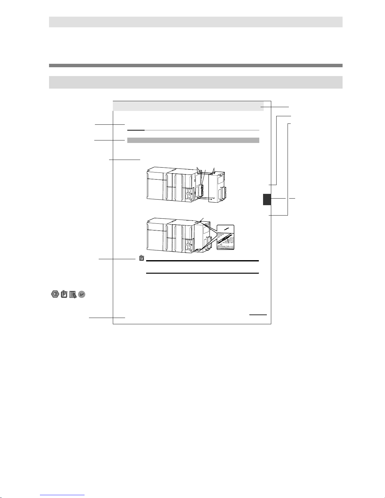
Page Structure
The following page structure is used in this manual.
4-9
4 Installation and Wi ring
NJ-seriesCPU Unit Hardware User’s Manual ( W500)
stinUgn
itnuoM3-4
4
stn
enopmoC
rellortnoCg
nitce
n
noC
1-3
-4
4-3 Mounting Units
The Units that make up an NJ-series Controlle r can be connected simply by pressing the Units together
and locking the sliders by moving them toward the back of the Units. The End Cover is co nnected in the
same way to the Uni t on the far right si de of the Controller.
1 Join the Units so t hat the connect ors fit exactl y.
2 The yellow sliders at the top and bottom of each Uni t lock the Units together. Move the slide rs
toward the back of the Units as shown below until t hey click into place.
Preca ution s for Cor rec t UsePreca ution s for Cor rec t Use
4-3-1 Connecting Controller Comp onents
Connector
Hook
Hook holes
Slider
Lock
Release
Move the sliders toward the back
until they lock into place.
Level 1 heading
Level 2 heading
Level 3 heading
Level 2 heading
A step in a procedure
Manual name
Special information
Level 3 heading
Page tab
Gives the current
headings.
Indicates a procedure.
Icons indicate
precautions, additional
information, or reference
information.
Gives the number
of the main section.
This illustration is provided only as a sample. It may not literally appear in this manual.
The sliders on the tops and bottoms of t he Power Supply Unit, CPU Unit, I/ O Units, Special I/ O
Units, and CPU Bus Units must be completely locked (until they click into place) after connec t ing
the adjacent Unit connectors.
Page 6

Manual Structure
4
NJ/NX-series Database Connection CPU Units User’s Manual (W527)
Special Information
Special information in this manual is classified as follows:
Note References are provided to moredetailed orrelated info
rmation.
Precautions for Safe Use
Precautions on what to doand what not to do to ensure safe usage of the product.
Precautions for Correct Use
Precautions on what to do and what not to do to ensure proper operation and performance.
Additional Information
Additional information to read as required.
This information is provided to increase understanding or make operation easier.
Version Information
Information on differences in specifications and functionality for CPU Units with different unit versions
and for different versions of the Sysmac Studio is given.
Precaution on Terminology
In this manual, “download” refers to transf erring data from Sysmac Studio to the physical Controller
and “upload” refers to transferring data from the physical Controller to Sysmac Studio.
For Sysmac Studio, synchronization is used to both upload and download data. Here, “sync hronize”
means to automatically compare the data for Sysmac Studio on the computer with the data in the
physical Controller and transfer the data in the direction that is specified by the user.
Page 7

Sections in this Manual
5
NJ/NX-series Database Connection CPU Units User’s Manual (W527)
Sections in this Manual
1
2
3
4
5
6
7
A
1
2
Introduction to the DB Connection Service
DB Connection Settings
How to Use Operation Logs
Other Functions
Basic Operations and Status Check
Programming the DB Connection Function
Troubleshooting
Appendix A
3
4
5
6
7
A
B
Appendix B
B
I
Index
I
Page 8

CONTENTS
6
NJ/NX-series Database Connection CPU Units User’s Manual (W527)
CONTENTS
Introduction .................................................................................................................... 1
Intended Audience .................................................................................................. 1
Applicable Products ................................................................................................ 1
Relevant Manuals .......................................................................................................... 2
Manual Structure ............................................................................................................ 3
Page Structure ........................................................................................................ 3
Special Information ................................................................................................. 4
Precaution on Terminology ..................................................................................... 4
Sections in this Manual .................................................................................................. 5
CONTENTS ................................................................................................................... 6
Terms and Conditions Agreement ................................................................................ 11
Warranty, Limitations of Liability ........................................................................... 11
Application Considerations ................................................................................... 12
Disclaimers .......................................................................................................... 12
Safety Precautions ....................................................................................................... 14
Precautions for Safe Use ............................................................................................. 15
Precautions for Correct Use ......................................................................................... 16
Regulations and Standards .......................................................................................... 17
Conformance to EU Directives ............................................................................. 17
Conformance to KC Standards ............................................................................. 18
Conformance to Shipbuilding Standards .............................................................. 18
Software Licenses and Copyrights ....................................................................... 18
Versions ....................................................................................................................... 19
Unit Versions ........................................................................................................ 19
Version Types ....................................................................................................... 19
Checking Versions ................................................................................................ 19
Unit Versions of CPU Units and Sysmac Studio Ver sions ................................... 22
Related Manuals .......................................................................................................... 23
Terminolog
y ................................................................................................................. 25
Revision History ........................................................................................................... 26
1 Introduction to the DB Connection Service ..................................................... 1-1
1-1 Overview and Features ................................................................................. 1-2
1-1-1 Overview .......................................................................................... 1-2
1-1-2 Features ........................................................................................... 1-3
1-2 DB Connection Service Specifications and System ....................................... 1-4
1-2-1 DB Connection Service Specifications ............................................ 1-4
Page 9

CONTENTS
7
NJ/NX-series Database Connection CPU Units User’s Manual (W527)
1-2-2 DB Connection System.................................................................... 1-7
1-3
Operation Flow of the DB Connection Service
................................................ 1-9
2 DB Connection Settings .................................................................................. 2-1
2-1 Starting Sysmac Studio and Creating a New Project ..................................... 2-2
2-1-1 Starting Sysmac Studio ................................................................... 2-2
2-1-2 Creating a New Project .................................................................... 2-2
2-1-3 Setting the Built-in EtherNet/IP Port ................................................ 2-4
2-1-4 Controller Setup ............................................................................... 2-4
2-2 DB Connection Settings ................................................................................. 2-5
2-2-1 DB Connection Service Settings ..................................................... 2-5
2-2-2 DB Connection Settings .................................................................. 2-8
3 Programming the DB Connection Function .................................................... 3-1
3-1 DB Access Procedure ................................................................................... 3-2
3-2 Creating a Structure Data Type ..................................................................... 3-3
3-2-1 Overview .......................................................................................... 3-3
3-2-2 Specifications of Structure Data Type for DB Access ..................... 3-3
3-2-3 How to Create a Structure Data Type for DB Access ................... 3-12
3-3 Creating a DB Map Variable ........................................................................ 3-15
3-3-1 DB Map Variables and DB Mapping .............................................. 3-15
3-3-2 Registration and Attributes of DB Map Variables .......................... 3-16
3-3-3 Restrictions on DB Map Variables ................................................. 3-17
3-4 Specifying the Table and Applying the Mapping .......................................... 3-18
3-4-1 DB Mapping by Executing a Create DB Map Instruction ............... 3-18
3-4-2 Clearing the Mapping of DB Map Variables .................................. 3-18
3-4-3 Restrictions on DB Mapping .......................................................... 3-19
3-5 Programming and Transfer .......................................................................... 3-22
3-5-1 Programming the DB Connection Service ..................................... 3-22
3-5-2 Displaying DB Connection Instructions on S ysmac Studio ........... 3-23
3-5-3 DB Connection Instruction Set ...................................................... 3-24
3-5-4 System-defined Variables .............................................................. 3-25
3-5-5 Simulation Debugging of DB Connection Instructions ................... 3-26
3-5-6 Transferring the DB Connection Settings and User Program ....... 3-26
3-6 Debugging in Design, Startup, and Operation Phas es ................................ 3-27
3-6-1 Design Phase ................................................................................ 3-27
3-6-2 Startup Phase ................................................................................ 3-27
3-6-3 Operation Phase ............................................................................ 3-27
4 Basic Operations and Status Check ............................................................... 4-1
4-1 Run Mode of DB Connection Service and Start/Stop Procedures ................. 4-2
4-1-1 Run Mode of the DB Connection Service ........................................ 4-2
4-1-2 How to Start/Stop the DB Connection Servic e ................................ 4-2
4-1-3 DB Connection Service is Stopped or Cannot be Started ............... 4-4
4-1-4 Changing the Run Mode of the DB Connection S ervice ................. 4-5
Page 10

CONTENTS
8
NJ/NX-series Database Connection CPU Units User’s Manual (W527)
4-2 Establishing/Closing a DB Connection .......................................................... 4-6
4-3 Checking the Status of DB Connection Service and each DB Connection ........................ 4-7
4-3-1 Operation Status of the DB Connection Service ............................. 4-7
4-3-2 Checking the Status of the DB Connection Service ........................ 4-8
4-3-3 Connection Status of each DB Connection ................................... 4-11
4-3-4 Checking the Status of each DB Connection ................................ 4-12
5 Other Functions ............................................................................................... 5-1
5-1 Examples of Using Functions ........................................................................ 5-2
5-2 Spool Function .............................................................................................. 5-4
5-2-1 Overview .......................................................................................... 5-4
5-2-2 Spooling System .............................................................................. 5-4
5-2-3 Applicable Instructions and Spooling Execution Conditions ............ 5-4
5-2-4 Memory Area Used by the Spool Function ...................................... 5-6
5-2-5 Spool Function Settings ................................................................... 5-8
5-2-6 How to Resend the SQL Statements Stored in the Spool M emory . 5-9
5-2-7 Clearing the SQL Statements from the Spool Memory ................. 5-10
5-2-8 Relationship with the DB Connection Instruct ions ......................... 5-12
5-2-9 How to Estimate the Number of SQL Statements t hat Can be Spooled
....................................................................................................... 5-14
5-3 DB Connection Service Shutdown Function ................................................ 5-15
5-3-1 Overview ........................................................................................ 5-15
5-3-2 Shutdown System .......................................................................... 5-16
5-3-3 How to Execute the Shutdown Function ........................................ 5-16
5-3-4 How to Check the Shutdown of the DB Connection Service ......... 5-17
5-4 How to Prevent Losing SQL Statements at Power Interrupti on ................... 5-18
5-4-1 Overview ........................................................................................ 5-18
5-4-2 Procedures ..................................................................................... 5-18
5-5 Timeout Monitoring Functions ..................................................................... 5-22
5-5-1 Timeout Monitoring Functions ....................................................... 5-22
5-5-2 Login Timeout ................................................................................ 5-23
5-5-3 Query Execution Timeout .............................................................. 5-23
5-5-4 Communications Timeout .............................................................. 5-24
5-5-5 Instruction Execution Timeout ....................................................... 5-24
5-5-6 Keep Alive Monitoring Time ........................................................... 5-24
5-6 Other Functions ........................................................................................... 5-26
5-6-1 Backup/Restore Function in the DB Connection Service .............. 5-26
5-6-2 Operation Authority Verification in the DB Connection Service ..... 5-28
6 How to Use Operation Logs ............................................................................ 6-1
6-1 Operation Logs .............................................................................................. 6-3
6-2 Execution Log ................................................................................................ 6-4
6-2-1 Overview .......................................................................................... 6-4
6-2-2 Application Procedure ...................................................................... 6-4
6-2-3 Setting the Execution Log ................................................................ 6-5
6-2-4 Checking the Execution Log ............................................................ 6-5
Page 11

CONTENTS
9
NJ/NX-series Database Connection CPU Units User’s Manual (W527)
6-2-5 Execution Log File Specifications .................................................... 6-5
6-3 Debug Log ................................................................................................... 6-10
6-3-1 Overview ........................................................................................ 6-10
6-3-2 Application Procedure ................................................................... 6-10
6-3-3 Setting the Debug Log ................................................................... 6-11
6-3-4 Starting Recording to Debug Log .................................................. 6-12
6-3-5 Stopping Recording to Debug Log ................................................ 6-13
6-3-6 Checking the Debug Log ............................................................... 6-14
6-3-7 Debug Log File Specifications ....................................................... 6-14
6-4 SQL Execution Failure Log .......................................................................... 6-18
6-4-1 Overview ........................................................................................ 6-18
6-4-2 Application Procedure ................................................................... 6-18
6-4-3 Setting the SQL Execution Failure Log ......................................... 6-18
6-4-4 Checking the SQL Execution Failure Log ..................................... 6-19
6-4-5 SQL Execution Failure Log File Specifications ............................. 6-19
6-5 SD Memory Card Operations ...................................................................... 6-22
6-5-1 Saving Operation Log Files on SD Memory Card ......................... 6-22
6-5-2 Directory Used for DB Connection Service ................................... 6-22
6-5-3 Operation Log Operations in Replacing the SD Memory Card ..... 6-23
6-5-4 Guidelines for SD Memory Card Replacement T i m e .................... 6-23
6-5-5 Replacement Timing of SD Memory Card ..................................... 6-24
6-6 Checking the Operation Logs ...................................................................... 6-25
6-6-1 How to Check the Operation Logs ................................................. 6-25
6-6-2 Checking the Log on the Operation Log Window in Sysmac Studio ................ 6-25
6-6-3 Checking the Log with the SD Memory Card ................................ 6-27
6-6-4 Checking the Log by Transfer using FTP Client Software ............ 6-27
7 Troubleshooting .............................................................................................. 7-1
7-1 Overview of Errors ......................................................................................... 7-2
7-1-1 How to Check for Errors .................................................................. 7-3
7-1-2 Errors Related to the DB Connection Service ................................. 7-5
7-2 Troubleshooting ............................................................................................. 7-7
7-2-1 Error Table ....................................................................................... 7-7
7-2-2 Error Descriptions .......................................................................... 7-15
Appendix A ........................................................................................................... A-1
A-1 DB Connection Instructions and Variables ................................................... A-2
A-1-1 DB Connection Instruction Set ........................................................ A-2
A-1-2 Variables Used in the DB Connection Instructio ns .......................... A-3
DB_Connect (Establish DB Connection) .................................................................... A-6
DB_Close (Close DB Connection) .............................................................................. A-9
DB_CreateMapping (Create DB Map) ...................................................................... A-11
DB_Insert (Insert DB Record) .................................................................................. A-14
DB_Update (Update DB Record) ............................................................................. A-18
Page 12

CONTENTS
10
NJ/NX-series Database Connection CPU Units User’s Manual (W527)
DB_Select (Retrieve DB Record) ............................................................................. A-34
DB_Delete (Delete DB Record) ................................................................................ A-39
DB_ControlService (Control DB Connection Service) ............................................................. A-54
DB_GetServiceStatus (Get DB Connection Service Status) ..................................................... A-60
DB_GetConnectionStatus (Get DB Connection Status) .......................................................... A-65
DB_ControlSpool (Resend/Clear Spool Data) ................................................................. A-71
DB_PutLog (Record Operation Log) ........................................................................ A-78
DB_Shutdown (Shutdown DB Connection Service) ............................................................... A-84
Appendix B ........................................................................................................... B-1
B-1 Task Design Procedure ................................................................................ B-2
B-1-1 Startup Time of DB Connection Service .......................................... B-2
B-1-2 Reference Values for Execution Time of DB Connection Instructions ................ B-4
B-1-3 How to Measure Execution Time of DB Connect i on Instructions .... B-7
B-1-4 Guideline for System Service Execution Time Rat i o ....................... B-8
B-1-5 Checking the System Service Execution Time Rat i o ...................... B-9
B-2 Execution Time of DB Connection Instructions ........................................................ B-11
B-2-1 Restrictions to Execution Time of DB Connecti on Instructions ..... B-11
B-2-2 Impact of Operation Log Recording on Execution T ime of DB
Connection Instructions ................................................................. B-17
B-2-3 How to Measure DB Response Time ............................................ B-18
B-2-4 Ensuring Equipment Performance (Takt T im e) by Monitoring
Instruction Execution Timeout ....................................................... B-19
B-3 Specifications ............................................................................................. B-20
B-3-1 General Specifications ................................................................... B-20
B-3-2 Performance Specifications ........................................................... B-20
B-3-3 Function Specifications .................................................................. B-20
B-4 Version Information .................................................................................... B-21
B-4-1 Unit Versions and Corresponding DB Connection S ervice
Versions ......................................................................................... B-21
B-4-2 DB Connection Functions That Were Added or Changed for Each Unit Version B-21
B-4-3 Actual Unit Version of CPU Unit and Unit Version Set in the
Sysmac Studio Project ................................................................... B-22
Index
Page 13

Terms and Conditions Agreement
11
NJ/NX-series Database Connection CPU Units User’s Manual (W527)
Terms and Conditions Agreement
Warranty, Limitations of Liability
Warranties
Exclusive Warranty
Omron’s exclusive warranty is that the Products will be free from defects in materials and
workmanship for a period of twelve months from the date of sale by Omron (or such other period
expressed in writing by Omron). Omron disclaim s all other warranties, express or implied.
Limitations
OMRON MAKES NO WARRANTY OR REPRESENTATION, EXPRESS OR IMPLIED, ABOUT
NON-INFRINGEMENT, MERCHANTABILITY OR FITNESS FOR A PARTICULAR PURPOSE OF
THE PRODUCTS. BUYER ACKNOWLEDGES THAT IT ALONE HAS DETERMINED THAT THE
PRODUCTS WILL SUITABLY MEET THE REQUIREMENTS OF THEIR INTENDED USE.
Omron further disclaims all warranties and responsibility of any type for claims or expenses based
on infringement by the Products or otherwise of any intellectual property right.
Buyer Remedy
Omron’s sole obligation hereunder shall be, at Om ron’s election, to (i) replace (in the form originally
shipped with Buyer responsible for labor charges for removal or replacement thereof) the
non-complying Product, (ii) repair the non-complyi ng Product, or (iii) repay or credit Buyer an
amount equal to the purchase price of the non-complying Product; provided that in no event shall
Omron be responsible for warranty, repair, i ndemnity or any other claims or expenses regarding the
Products unless Omron’s analysis confirms that the Products were properly handled, stored,
installed and maintained and not subject to contamination, abuse, misuse or inappropriate
modification. Return of any Products by Buyer m ust be approved in writing by Omron before
shipment. Omron Companies shall not be liable for the suitability or unsuitability or the results from
the use of Products in combination with any electrical or electronic components, circuits, system
assemblies or any other materials or substances or environments. Any advice, recommendations or
information given orally or in writing, are not t o be construed as an amendment or addition to the
above warranty.
See http://www.omron.com/global/ or contact your Omron representative for published information.
Page 14

Terms and Conditions Agreement
12
NJ/NX-series Database Connection CPU Units User’s Manual (W527)
Limitation on Liability; Etc
OMRON COMPANIES SHALL NOT BE LIABLE FOR SPECIAL, INDIRECT, INCIDENTAL, OR
CONSEQUENTIAL DAMAGES, LOSS OF PROFITS OR PRODUCTION OR COMMERCIAL LOSS
IN ANY WAY CONNECTED WITH THE PRODUCTS, WHETHER SUCH CLAIM IS BASED IN
CONTRACT, WARRANTY, NEGLIGENCE OR STRICT LIABILITY.
Further, in no event shall liability of Omron Companies exceed the individual price of the Product on
which liability is asserted.
Application Considerations
Suitability of Use
Omron Companies shall not be responsible for conformity with any standards, codes or regulations
which apply to the combination of the Product in the Buyer’s application or use of the Product. At
Buyer’s request, Omron will provide applicable third party certification documents identifying ratings
and limitations of use which apply to the Product. Thi s information by itself is not sufficient for a
complete determination of the suitability of the Product in combination with the end product, machine,
system, or other application or use. Buyer shall be solely responsible for determining appropriateness
of the particular Product with respect to Buyer’s application, product or system. Buyer shall take
application responsibility in all cases.
NEVER USE THE PRODUCT FOR AN APPLICATION INVOLVING SERIOUS RISK TO LIFE OR
PROPERTY WITHOUT ENSURING THAT THE SYSTEM AS A WHOLE HAS BEEN DESIGNED TO
ADDRESS THE RISKS, AND THAT THE OMRON PRODUCT(S) IS PROPERLY RATED AND
INSTALLED FOR THE INTENDED USE WITHIN THE OVERALL EQUIPMENT OR SYSTEM.
Programmable Products
Omron Companies shall not be responsible for the user’s programming of a programmable Product,
or any consequence thereof.
Disclaimers
Performance Data
Data presented in Omron Company websites, catalogs and other materials is provided as a guide for
the user in determining suitability and does not c onstitute a warranty. It may represent the result of
Omron’s test conditions, and the user must correlate it to actual application requirements. Actual
performance is subject to the Omron’s Warranty and Limitations of Liability.
Change in Specifications
Product specifications and accessories may be changed at any time based on improvements and
other reasons. It is our practice to change part numbers when published ratings or features are
changed, or when significant construction changes are made. However, some specifications of the
Product may be changed without any notice. When in doubt, special part numbers may be assigned
to fix or establish key specifications for your a pplication. Please consult with your Omron’s
representative at any time to confirm act ual specifications of purchased Product.
Page 15

Terms and Conditions Agreement
13
NJ/NX-series Database Connection CPU Units User’s Manual (W527)
Errors and Omissions
Information presented by Omron Companies has been checked and is believed to be accurate;
however, no responsibility is assumed for clerical, typographical or proofreading errors or omissions.
Page 16

Safety Precautions
14
NJ/NX-series Database Connection CPU Units User’s Manual (W527)
Safety Precautions
Refer to the following manuals for safety precautions.
• NX-series CPU Unit Hardware User’s Manual (Cat. No. W535)
• NJ-series CPU Unit Hardware User’s M a nual (Cat. No. W500)
For safety precautions on NJ501-4320, please contact our sales representative and check with the
product specification document or other documentation.
Page 17

Precautions for Safe Use
15
NJ/NX-series Database Connection CPU Units User’s Manual (W527)
Precautions for Safe Use
Refer to the following manuals for precauti ons f or safe use.
• NX-series CPU Unit Hardware User’s M a nual (Cat. No. W535)
• NJ-series CPU Unit Hardware User’s M a nual (Cat. No. W500)
For precautions for safe use on NJ501-4320, please contact our sales representative and check with
the product specification document or other d ocumentation.
Page 18

Precautions for Correct Use
16
NJ/NX-series Database Connection CPU Units User’s Manual (W527)
Precautions for Correct Use
This section describes the precautions for correct use in the DB Connection Service.
Refer to the following manuals for other pre cautions for correct use.
• NX-series CPU Unit Hardware User’s Manual (Cat. No. W535)
• NJ-series CPU Unit Hardware User’s M a nual (Cat. No. W500)
For precautions for correct use on NJ501-4320, please contact our sales r epresentative and check
with the product specification document or ot her documentation.
• For the NJ-serie s CPU Unit, when the Spool function is enabled, the DB Connection Service uses
the following EM Banks according to the CPU Unit model . If the EM banks are used for processes
other than the DB Connection Service, the Spool d ata in the EM Banks will be overwritten. Do not
use the EM Banks that are used by the DB Connection Service for processes other than the DB
Connection Service.
NJ501-20: EM Bank No. 9 to 18 (E9_00000 to E18_32767)
NJ101-20: EM Bank No. 1 to 3 (E1_00000 to E3_32767)
Page 19

Regulations and Standards
17
NJ/NX-series Database Connection CPU Units User’s Manual (W527)
Regulations and Standards
Conformance to EU Directives
Applicable Directives
• EMC Directives
• Low Voltage Directive
Concepts
EMC Directive
OMRON devices that comply with EU Directives al so conform to the related EMC standards so that
they can be more easily built into other devices or the overall machine. The actual products have
been checked for conformity to EMC standards.*
Whether the products conform to the standa rds in the system used by the customer, however, must
be checked by the customer. EMC-related performance of the OMRON devices that comply with
EU Directives will vary depending on the configuration, wiring, and other conditions of the
equipment or control panel on which the OMR ON devices are installed. The customer must,
therefore, perform the final check to confirm t hat devices and the overall machine conform to EMC
standards.
*
Applicable EMC (Electromagnetic Compatibi li ty) standards are as follows:
EMS (Electromagnetic Susceptibility): EN 61131-2
EMI (Electromagnetic Interference): EN 61131-2
Radiated emission: 10-m regulations
Low Voltage Directive
Always ensure that devices operating at voltages of 50 to 1,000 VAC and 75 to 1,500 VDC meet the
required safety standards. The applicable di rective is EN 61010-2-201.
Conformance to EU Directives
The NJ/NX-series Controllers comply with EU Directives. T o ensure that the machine or device in
which the NJ/NX-series Controller is used complies with EU Directives, the Controller must be
installed as follows:
• The NJ/NX-series Controller must be installed within a control panel.
• You must use the power supply in SELV specific ations for the DC power supplies connected to
DC Power Supply Units and I/O Units.
• NJ/NX-series Controllers that comply with EU Directives also conform to the Common
Emission Standard. Radiated emission characteristics (10-m regulations) may vary depending
on the configuration of the control panel use d, other devices connected to the control panel,
wiring, and other conditions.
You must therefore confirm that the overall machine or equipment complies with EU
Directives.
Page 20
Regulations and Standards
18
NJ/NX-series Database Connection CPU Units User’s Manual (W527)
Conformance to KC Standards
Observe the following precaution if you use NX-series Units in Korea.
Class A Device (Broadcasting Communications Device for Office Use)
This device obtained EMC registration for office use (Class A), and it is intended to be used in places
other than homes.
Sellers and/or users need to take note of this.
Conformance to Shipbuilding Standards
Some Database Connection CPU Units comply wit h shipbuilding standards. If you use a Database
Connection CPU Unit that complies with shipbui ldi ng standards and the machinery or system in which
you use the Database Connection CPU Unit must also comply with the standards, consult with your
OMRON representative. Application conditions are defined according to the installation location.
Application may not be possible for some installation locations.
Usage Conditions for NK and LR Shipbuilding Standards
• The NJ-series Controller must be installed wit hi n a control panel.
• Gaps in the door to the control panel must be compl etely filled or covered with gaskets or other
material.
• The following noise filter must be connected to the power supply line.
Noise Filter
Manufacturer
Model
Cosel Co., Ltd.
TAH-06-683
Software Licenses and Copyrights
This product incorporates certain third part y software. The license and copyright information
associated with this software is available at ht tp://www.fa.omron.co.jp/nj_info_e/.
Page 21
Versions
19
NJ/NX-series Database Connection CPU Units User’s Manual (W527)
Versions
Unit Versions
Hardware revisions and unit versions are used t o m anage the hardware and software in NJ/NX-series
Units and EtherCAT slaves. The hardware revision or unit version is updated each time there is a
change in hardware or software specifications. Even when two Units or EtherCAT slaves have the
same model number, they will have functional or performance differences if they have different
hardware revisions or unit versions.
Version Types
There are two types of versions. One is unit v ersion and the other is DB Connection Service version.
These versions are managed independently. Therefore, only one of them may be upgraded.
Unit Version
This is the version of hardware and software of Units and EtherCAT slaves. The version is upgraded
at every specification change in the hardware or sof tware. Therefore, the functionality and
performance differ by the versions even in the same model number of Units and EtherCAT slaves.
DB Connection Service Version
This is the version of DB Connection Service implemented in the Database Connection CPU Units.
The version is upgraded at every specification change in the DB Connection Service.
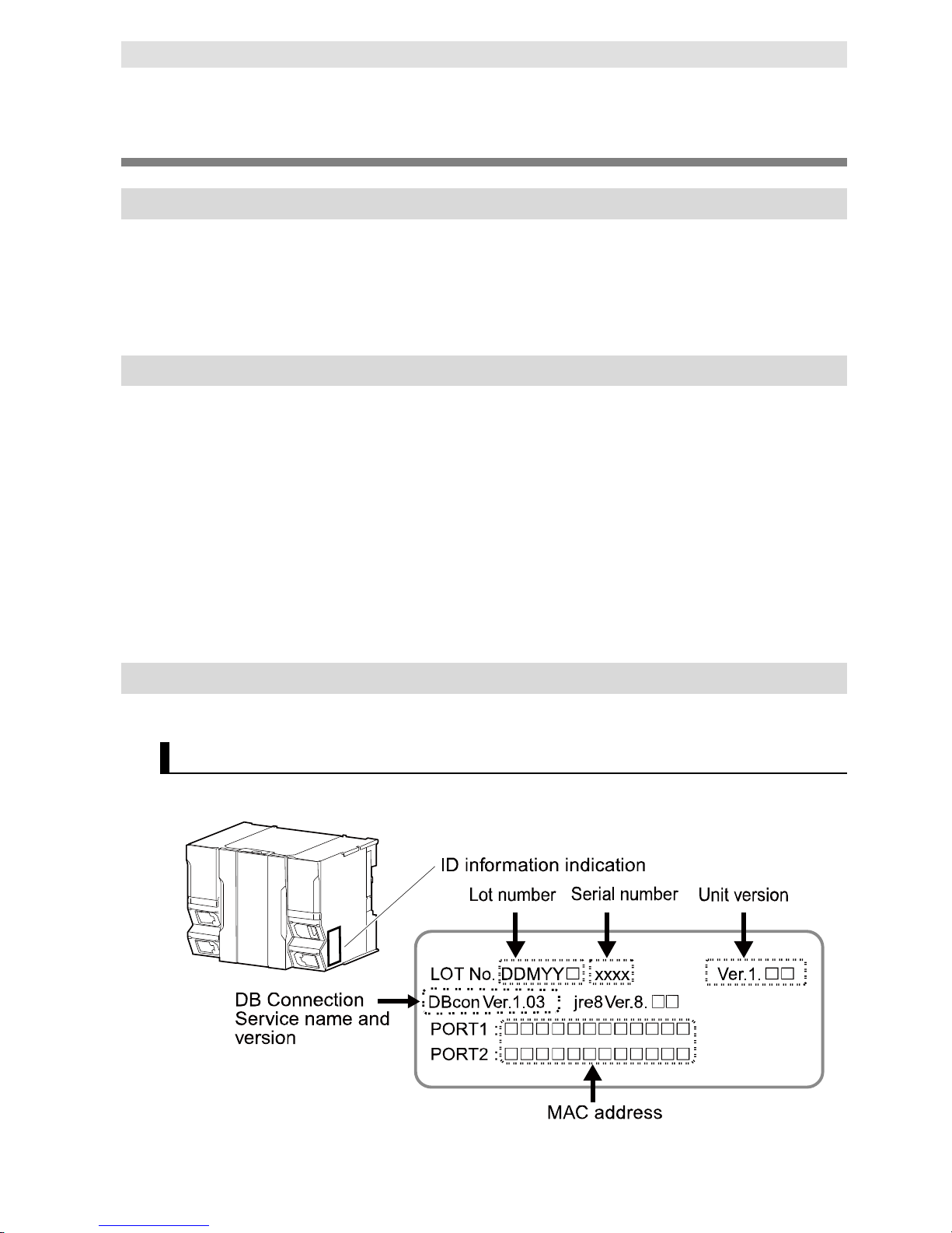
Checking Versions
You can check versions on the ID information indications or with Sysmac Studio.
Checking Unit Versions on ID Information Label
The unit version is given on the ID information indi cation on the side of the product.
The ID information on an NX-series NX701-20 CPU Unit is shown below.
Page 22

Versions
20
NJ/NX-series Database Connection CPU Units User’s Manual (W527)
The ID information on an NJ-series NJ501-1520 CPU Unit is shown below.
Page 23

Versions
21
NJ/NX-series Database Connection CPU Units User’s Manual (W527)
Checking Unit Versions with the Sysmac Studio
You can use the Sysmac Studio to check unit versions. The procedure is different for Units and for
EtherCAT slaves.
Checking the Unit Version of an NX-series CPU Unit
You can use the Production Information while the Sysmac Studio is online to check the unit version
of a Unit. You can do this for the CPU Unit. For an NX1P2 CPU Unit, you can also check the unit
versions of the NX Units on the CPU Rack and O ption Boards.
1. Right-click CPU Rack under Configurations and Setup - CPU/Expansion Racks in the
Multiview Explorer and select Production Information.
The Production Information Dialog Box is displayed.
Checking the Unit Version of an NJ-series CPU Unit
You can use the Production Information while the Sysmac Studio is online to check the unit version
of a Unit. You can do this for the CPU Unit, CJ-series Special I/O Units, and CJ-series CPU Bus
Units. You cannot check the unit versions of CJ-series Basic I/O Units with the Sysmac Studio.
Use the following procedure to check the unit version.
1. Double-click CPU/Expansion Racks under Configurations and Setup in the Multiview Explorer.
Or, right-click CPU/Expansion Racks under Configurations and Setup and select Edit from the
menu.
The Unit Editor is displayed.
2. Right-click any open space in the Unit Editor and select Production Information.
The Production Information Dialog Box is displayed.
Page 24

Versions
22
NJ/NX-series Database Connection CPU Units User’s Manual (W527)
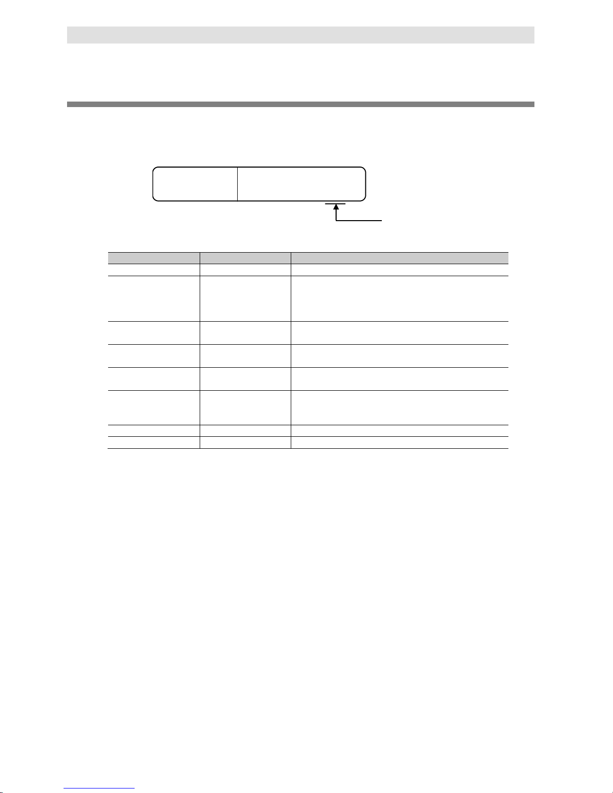
Changing Information Displayed in Production Information Dialog Box
1. Click the Show Detail or Show Outline Button at the lower right of the Production Information
Dialog Box.
The view will change between the production information details and outline.
Outline View Detail View
The information that is displayed is different for the Outline View and Detail View. The Detail View
displays both the unit versions and DB Connection Service version. The Outline View displays
only the unit versions.
Note The hardware revision is separated by "/" and displayed on the right of the har dware version. The
hardware revision is not displayed for the Unit that the hardware revision is in blank.
Unit Versions of CPU Units and Sysmac Studio Versions
The functions that are supported depend on the unit version of the NJ/NX-series CPU Unit. The
version of Sysmac Studio that supports the functions that were added for an upgrade is also required
to use those functions. Refer to B-4 Version Information for the relationship between the unit versions
of the NJ/NX-series Database Connection CPU Units and the Sysmac Studio versions, and for the
functions that are supported by each unit version.
Page 25

Related Manuals
23
NJ/NX-series Database Connection CPU Units User’s Manual (W527)
Related Manuals
The following manuals are related to this manual. U se these manuals for reference.
Manual name
Cat. No.
Model numbers
Application
Description
NX-series CPU Unit
Hardware User’s Manual
W535
NX701-
Learning the
basic
specifications of
the NX701 CPU
Units,
including
introductory
information,
designing,
installation,
and
maintenance.
Mainly hardware
information is
provided.
An introduction to the entire NX701 system is
provided along with the following information on
the CPU Unit.
• Features and system configuration
• Introduction
• Part names and functions
• General specifications
• Installation and wiring
• Maintenance and inspection
NJ-series CPU Unit
Hardware User’s Manual
W500
NJ501-
NJ301-
NJ101-
Learning the
basic
specifications of
the NJ-series
CPU Units,
including
introductory
information,
designing,
installation, and
maintenance.
Mainly hardware
information is
provided.
An introduction to the entire NJ-series system is
provided along with the following information on
the CPU Unit.
• Features and system configuration
• Introduction
• Part names and functions
• General specifications
• Installation and wiring
• Maintenance and inspection
NJ/NX-series CPU Unit
Software User’s Manual
W501
NX701-
NX1P2-
NJ501-
NJ301-
NJ101-
Learning how to
program and set
up an
NJ/NX-series
CPU Unit. Mainly
software
information is
provided.
The following information is provided on a
Controller built with an NJ/NX-series CPU Unit.
• CPU Unit operation
• CPU Unit features
• Initial settings
• Programming based on IEC 61131-3 language
specifications
NJ/NX-series Instructions
Reference Manual
W502
NX701-
NX1P2-
NJ501-
NJ301-
NJ101-
Learning detailed
specifications on
the basic
instructions of an
NJ/NX-series
CPU Unit.
The instructions in the instruction set (IEC
61131-3 specifications) are described.
NJ/NX-series CPU Unit
Motion Control User’s
Manual
W507
NX701-
NX1P2-
NJ501-
NJ301-
NJ101-
Learning about
motion control
settings and
programming
concepts.
The settings and operation of the CPU Unit and
programming concepts for motion control are
described.
NJ/NX-series Motion
Control Instructions
Reference Manual
W508
NX701-
NX1P2-
NJ501-
NJ301-
NJ101-
Learning about
the specifications
of the motion
control
instructions.
The motion control instructions are described.
NJ/NX-series CPU Unit
Built-in EtherCAT Port
User’s Manual
W505
NX701-
NX1P2-
NJ501-
NJ301-
NJ101-
Using the built-in
EtherCAT port on
an NJ/NX-series
CPU Unit.
Information on the built-in EtherCAT port is
provided. This manual provides an introduction
and provides information on the configuration,
features, and setup.
NJ/NX-series CPU Unit
Built-in EtherNet/IPTM Port
User’s Manual
W506
NX701-
NX1P2-
NJ501-
NJ301-
NJ101-
Using the built-in
EtherNet/IP port
on an
NJ/NX-series
CPU Unit.
Information on the built-in EtherNet/IP port is
provided. Information is provided on the basic
setup, tag data links, and other features.
Page 26

Related Manuals
24
NJ/NX-series Database Connection CPU Units User’s Manual (W527)
Manual name
Cat. No.
Model numbers
Application
Description
NJ/NX-series Database
Connection CPU Units
User’s Manual
W527
NX701-20
NJ501-20
NJ101-20
Using the
database
connection
service with
NJ/NX-series
Controllers.
Describes the database connection service.
NJ/NX-series
Troubleshooting
Manual
W503
NX701-
NX1P2-
NJ501-
NJ301-
NJ101-
Learning about
the errors that
may be detected
in an
NJ/NX-series
Controller.
Concepts on managing errors that may be
detected in an NJ/NX-series Controller and
information on individual errors are described.
Sysmac Studio Version 1
Operation Manual
W504
SYSMAC -SE2
Learning about
the operating
procedures and
functions of
Sysmac Studio.
Describes the operating procedures of Sysmac
Studio.
Page 27

Terminology
25
NJ/NX-series Database Connection CPU Units User’s Manual (W527)
Terminology
Term
Description
Column
One of the information layers of each DB. Refers to the columns of each table.
DB
Refers to a database in a server.
DB Connection
Refers to a virtual communication path established between CPU Unit and DB.
DB Connection function
Used to connect a CPU Unit to a DB. This function operates on a CPU Unit.
DB Connection Instruction
Refers to special instructions for the DB Connection Service.
DB Connection Service This service provides the DB Connection function to connect a CPU Unit to a DB.
In the ID information indication on the side of the CPU Unit and in Sysmac Studio, this service is
indicated as “DBCon”.
DB Connection Service shutdown
function
Used to shut down the DB Connection Service after automatically saving the Operation Log files
into the SD Memory Card.
DB mapping Means to assign each member of a DB Map Variable to the corresponding column of a table in
the connected DB.
DB Map Variable
Refers to a variable that uses a structure data type for DB access as its data type.
Debug Log One of the Operation Logs. This log is used for recording which SQL statements are executed,
and parameters and execution result of each SQL statements.
EM Area Refers to EM Area of the memory for CJ-series Units. The data in this area are retained even if
the power supply to the CPU Unit is cycled (i.e. ON → OFF → ON) or the operating mode of the
CPU Unit is changed (i.e. PROGRAM mode ⇔ RUN mode).
Execution Log One of the Operation Logs. This log is used to record the executions of the DB Connection
Service.
Operation Log Used to trace the operations of the DB Connection function on the CPU Unit. There are three
types of Operation Logs; Execution Log, Debug Log, and SQL Execution Failure Log.
Run mode of the DB Connection
Service
Used to switch whether to actually access the DB or to normally end the instructions without
accessing the DB when DB Connection Instructions are executed.
Spool memory
Refers to the memory area for storing the SQL statements in the Spool function.
Spool function Used to store some SQL statements for inserting records into the DB or updating the records in
the DB that could not be executed due to a network failure.
Spool data
Refers to the SQL statements stored in the Spool memory.
Structure data type for DB access Refers to structure data type where all or some of the columns of a specified table are registered
as structure members.
SQL Stands for Structured Query Language, which is one of the languages for DB processing such
as data read/write.
SQL Execution Failure Log One of the Operation Logs. This log is used to record execution failure of SQL statements in the
DB.
SQL statement Refers to the statements that show a specific instruction used for DB operations such as data
read/write.
Table
One of the information layers of each DB, which contains data.
Page 28
Revision History
26
NJ/NX-series Database Connection CPU Units User’s Manual (W527)
Revision History
A manual revision code appears as a suffix to the catalog number on the front and back covers of the
manual.
Revision code
W527
-E1-08
Cat. No.
Revision code
Date
Revised content
01
April 2013
Original production
02 August 2013 • Added description of the time specified for timeout of DB
Connection Instructions.
P5-10, A-16, A-21, A-37, and A-41
• Corrected mistakes.
03 February 2014 Added description of the functions supported by the DB
Connection Service version 1.01 or higher.
04 July 2014 • Added NJ501-4320.
• Corrected mistakes.
05 November 2015 • Added NJ101-20.
• Corrected mistakes.
06 December 2015 • Added description of the functions supported by the DB
Connection Service version 1.02 or higher.
• Corrected mistakes.
07
June 2016
Updated the EtherNet/IP logo.
08
January 2018
Added NX701-20.
Page 29

1-1
1
NJ/NX-series Database Connection CPU Units User’s Manual (W527)
1
This section provides an introduction to the DB Connect i on Service.
1-1 Overview and Features ................................................................................. 1-2
1-1-1 Overview ...........................................................................................1-2
1-1-2 Features............................................................................................1-3
1-2 DB Connection Service Specifications and System ...................................... 1-4
1-2-1 DB Connection Service Specifications .............................................1-4
1-2-2 DB Connection System ....................................................................1-7
1-3 Operation Flow of the DB Connection Service .............................................. 1-9
Introduction to
the DB Connection Service
Page 30
1 Introduction to the DB Connection Service
1-2
NJ/NX-series Database Connection CPU Units User’s Manual (W527)
1-1 Overview and Features
This section describes the overview and features of the DB Connection Service.
1-1-1 Overview
The SYSMAC NJ/NX-series Controllers are next-generation machine automation controlle r s t hat
provide the functionality and high-speed performan ce that are r equired for m achine cont rol. They
provide the safety, reliability, and maintainabil i ty that are required of industrial controllers.
The NJ/NX-series Controllers provide the functionality of previous OMRON PLCs, and they also
provide the functionality that is required for motion control. Synchronized control of I/O devices
on high-speed EtherCAT can be applied to safety devices, vision systems, motion equipment,
discrete I/O, and more.
OMRON offers the new Sysmac Series of control devices designed with unified communications
specifications and user interface specifications. The NJ/NX-series Machine Automation
Controllers are part of the Sysmac Series. You can use them together with EtherCAT slaves,
other Sysmac products, and the Sysmac Studio Automation Software to achieve optimum
functionality and ease of operation. With a system that is created fro m Sysmac produ cts, you can
connect components and operate the system throu gh unified concepts and usability.
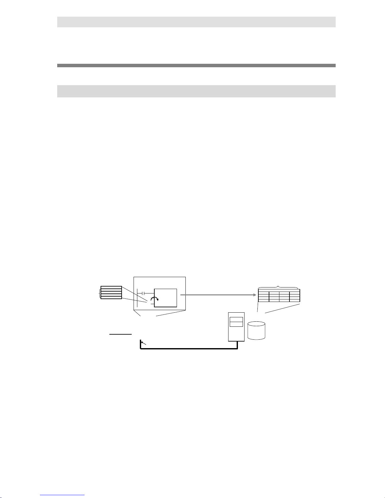
The DB Connection Service is a function to insert, update, retrieve, and delete records to/from a
relational database (hereinafter called “DB”) on a server connected to the built-in EtherNet/IP
port of an NJ/NX-series CPU Unit by executing special instructions (called “DB Connection
Instruction”) on the NJ/NX-series CPU Unit.
The DB Connection Service is available with the NX-series NX701-@@20 CPU Unit and
NJ-series NJ501-@@20 and NJ101-@@20 CPU Units.
Structure
variables
Server
Relational Database
Sysmac Studio
NJ/NX-series Database Connection CPU Unit
EtherNet/IP port
DB Connection Instruction
e.g. DB_Insert instruction
DBConnection
MapVar
abc
▼TABLE
Field1 :10
Field2 :20
Field3 :40
Field4 :100
TABLE
Field1
Field2
Field3
Field4
10
20
40
100
e.g. Insert a record
LAN
Oracle Database of Oracle Corporation, SQL Server of Microsoft Corporation, DB2 for Linux,
UNIX and Windows of IBM Corporation, MySQL of O racle Corporation, Firebird of Firebird
Foundation Incorporated, and PostgreSQL of PostgreSQL Global Development Group are
supported.
*1
NJ501-@@20 and NX701-@@20 CPU Units can access up to three databases on up to three
servers.
*2
It is possible to access more than one database in one or m ore servers. You can
realize flexible operations such as switching the database to access according to the specified
data and SQL operations (such as INSERT/SELECT ) and connecting to another database in a
different server when a database cannot be conne ct ed, for example, due to a server problem.
*1 The connectable databases a r e di fferent between NJ501-1@20/NJ101-@@20 and
NJ501-4320. Refer to 1-2-1 DB Connection S ervice Specifications for the conn ectable
databases.
*2 An NJ101-@@20 can access only one database.
Page 31

1 Introduction to the DB Connection Service
1-3
1
NJ/NX-series Database Connection CPU Units User’s Manual (W527)
1-1-2 Features
1-1 Overview and Features
1-1-2 Features
No Special Unit, Tool, nor Middleware Required
No special Unit is required for the DB Connection fun ction. You can use the NJ/NX -series CPU
Units.
No special tool is required for the DB Connection function. You can use Sysmac Studio.
The server does not need any special middleware for connection to the NJ/NX -series CPU
Units.
Easy Access to the DB
The SQL operations such as INSERT and SELECT can be easily executed.
No special knowledge of SQL statements is required.
Variables for DB access can be defined just by creating a structure for the table that you want t o
access.
You can easily control the execution timing and prepare the write values because the S Q L
operations can be executed by special instructions.
Recording of Operation Logs
You can save the execution result logs of special instructions and processing (i.e. internal SQL
statements) as a log file into the SD Memory Card mounted in the CPU Unit. Also, you can
check the logs using Sysmac Studio or FTP client software.*
* For saving the log files, an SD Memory Card is provided with each Database Connection CPU
Unit. The SD Memory Card can be also used for any purposes other than DB Connecti on
functions such as reading from and writing to the files in the SD Memory Card using
instructions.
Fail-safe Design against Errors and Power Interruption
You can spool the data (i.e. internal SQL statements) if the data cannot be sent due to an
information exchange error with the DB, and execut e the processing when the communications
are recovered from the failure.
You can automatically save the Operation Logs by shutting down the DB Connection Service
when turning OFF the power supply to the CPU Unit.
Making a Library of DB Access Function
You can provide and reuse the special instructions as a library file by describing each special
instruction as a user-defined function block.
Page 32

1 Introduction to the DB Connection Service
1-4
NJ/NX-series Database Connection CPU Units User’s Manual (W527)
1-2 DB Connection Service
Specifications and System
This section describes the specifications and system of the DB Connection Service.
1-2-1 DB Connection Service Specifications
This section describes the specifications of the DB C onnection Service. Refer to B-3
Specifications for the general specificati ons, performance specifications, and function
specifications of the Database Connection CPU Units.
Refer to B-4 Version Information for the information on version upgrades of the DB Connection
Service.
Item
Description
CPU Unit model Special models*1. The other functions are same as the
NX-series NX701-@@20 CPU Unit, NJ-series NJ501-@@00
CPU Unit, or NJ101-@@00 CPU Unit.
NX701-1720: 256-axis type
NX701-1620: 128-axis type
NJ501-1520: 64-axis type
NJ501-1420: 32-axis type
NJ501-1320: 16-axis type
NJ501-4320: 16-axis type
NJ101-1020: 2-axis type
NJ101-9020: No-axis type
Supported DB *2 For the supported DB, refer to Supported DB and
Corresponding Versions below.
Number of DB Connections (Number of databases
that can be connected at the same time)
NX701-@@20: 3 connections max.*3
NJ501-@@20: 3 connections max.
*3
NJ101-@@20: 1 connection max.
Instruction Supported operations The following operations can be performed by executing DB
Connection Instructions in the NJ/NX-series CPU Units.
Inserting records (INSERT), Updating records (UPDATE),
Retrieving records (SELECT), and Deleting records (DELETE)
Number of columns in an INSERT
operation
SQL Server: 1,024 columns max
Oracle Database: 1,000 columns max.
DB2: 1,000 columns max.
MySQL: 1,000 columns max.
Firebird: 1,000 columns max.
PostgreSQL: 1,000 columns max.
Number of columns in an UPDATE
operation
SQL Server: 1,024 columns max.
Oracle Database: 1,000 columns max.
DB2: 1,000 columns max.
MySQL: 1,000 columns max.
Firebird: 1,000 columns max.
PostgreSQL: 1,000 columns max.
Number of columns in a SELECT
operation
SQL Server: 1,024 columns max.
Oracle Database: 1,000 columns max.
DB2: 1,000 columns max.
MySQL: 1,000 columns max.
Firebird: 1,000 columns max.
PostgreSQL: 1,000 columns max.
Number of records in the output of a
SELECT operation
65,535 elements max., 4 MB max.
Page 33

1 Introduction to the DB Connection Service
1-5
1
NJ/NX-series Database Connection CPU Units User’s Manual (W527)
1-2-1 DB Connection Service Specifications
1-2 DB Connection Service
Specifications and System
Item
Description
Instruction
Number of DB Map Variables for
which a mapping can be created
NX701-@@20/NJ501-1@20
SQL Server: 60 variables max.
Oracle Database: 30 variables max.
DB2: 30 variables max.
MySQL: 30 variables max.
Firebird: 15 variables max.
PostgreSQL: 30 variables max.
Even if the number of DB Map Variables has not reached the
upper limit, the total number of members of structures used as
data type of DB Map Variables is 10,000 members max.
NJ501-4320
SQL Server: 15 variables max.
Oracle Database: 15 variables max.
MySQL: 15 variables max.
Even if the number of DB Map Variables has not reached the
upper limit, the total number of members of structures used as
data type of DB Map Variables is 10,000 members max.
NJ101-@@20
SQL Server: 15 variables max.
Oracle Database: 15 variables max.
DB2: 15 variables max.
MySQL: 15 variables max.
Firebird: 15 variables max.
PostgreSQL: 15 variables max.
Even if the number of DB Map Variables has not reached the
upper limit, the total number of members of structures used as
data type of DB Map Variables is 10,000 members max.
Run mode of the DB Connection Service Operation Mode or Test Mode
Operation Mode:
When each instruction is executed, the service actually
accesses the DB.
Test Mode:
When each instruction is executed, the service ends the
instruction normally without accessing the DB actually.
Spool function Used to store SQL statements when an error occurred and
resend the statements when the communications are
recovered from the error.
*4
NX701-@@20: 2 MB
NJ501-@@20: 1 MB
NJ101-@@20: 192 KB
Operation Log function The following three types of logs can be recorded.
Execution Log: Log for tracing the executions of the DB
Connection Service.
Debug Log: Detailed log for SQL statement executions of the
DB Connection Service.
SQL Execution Failure Log: Log for execution failures of SQL
statements in the DB.
DB Connection Service shutdown function Used to shut down the DB Connection Service after
automatically saving the Operation Log files into the SD
Memory Card.
*1 The CIP (Common Industrial Pr otocol) communications using the built-in EtherNet/IP port
support the same functions as with the following CPU models. Therefore, when executing
the EtherNet/IP tag data link function, please specify the following CPU models on Network
Configurator. The following models are also displayed in Sysmac Gateway or CX-Compolet.
• NX701-1700 for NX701-1720
• NX701-1600 for NX701-1620
• NJ501-1500 for NJ501-1520
• NJ501-1400 for NJ501-1420
Page 34

1 Introduction to the DB Connection Service
1-6
NJ/NX-series Database Connection CPU Units User’s Manual (W527)
• NJ501-1300 for NJ501-1320
• NJ501-4300 for NJ501-4320
• NJ101 for NJ101-@@20
*2 Connections to the DB on the cloud are not supported.
*3 When two or more DB Connections ar e es tablished, the operation cannot be guaranteed if
you set different database types for the c onnections.
*4 Refer to 5-2-9 How to Estimate the Number of SQL Statements that Can be Spoole d for the
information.
Supported DB and Corresponding Versions
CPU Unit
model
Manufacturer name, DB name
Microsoft
Corporation:
SQL Server
Oracle
Corporation:
Oracle
Database
IBM
Corporation:
DB2 for Linux,
UNIX and
Windows
Oracle
Corporation:
MySQL
Community
Edition *1
Firebird
Foundation
Incorporated:
Firebird
PostgreSQL
Global
Development
Group:
PostgreSQL *2
NX701-20 Corresponding
version: 2008,
2008R2, 2012,
2014, or 2016
Corresponding
version: 10g,
11g, or 12c
Corresponding
version: 9.5,
9.7, 10.1, 10.5,
or 11.1
Corresponding
version: 5.1, 5.5,
5.6, or 5.7
Corresponding
version: 2.1 or
2.5
Corresponding
version: 9.2, 9.3,
9.4, 9.5, or 9.6
NJ501-20/
NJ101-20
Corresponding
version: 2008,
2008R2, 2012,
or 2014
Corresponding
version: 9.5,
9.7, 10.1, or
10.5
Corresponding
version: 5.1, 5.5,
or 5.6
Corresponding
version: 9.2, 9.3,
or 9.4
NJ501-4320
Not supported.
Not supported.
Not supported.
*1 The supported storage engines of the DB are InnoDB and MyISAM.
*2 When you connect the CPU Unit to PostgreSQL, make the following setting to set the locale
of the PostgreSQL to C. Otherwise, the error messages are not correctly displayed.
Change the value of lc_messages in the postgresql.conf file stored in the data folder under
the installation folder of PostgreSQL and restart the PostgreSQL.
lc_messages = 'C'
Page 35

1 Introduction to the DB Connection Service
1-7
1
NJ/NX-series Database Connection CPU Units User’s Manual (W527)
1-2 DB Connection Service
Specifications and System
1-2-2 DB Connection System
1-2-2 DB Connection System
This section describes the basic and other systems of the DB Connection function.
Refer to 1-3 Operation Flow of the DB Connection Service for the operation flow.
Basic System
The following figure shows the basic system of the DB Connection function.
Sysmac Studio
abc
Data 1
Data 2
Data 3
Data 4
CPU Unit
DB Mapping (d)
(*)
SQL statement
sent (f)
(c) DB Connection Service
User Program
EtherNet/IP port
DB Map Variable (b)
*: DB Mapping (d)
▼TABLE
Field1
Field2
Field3
Field 4
Structure data type
for DB access (a)
Server
Relational
Database
TABLE
Field1
Field2
Field3
Field4
Data 1
Data 2
Data 3
Data 4
DB table
(in Operation Mode)
INSERT ...
Mapping
DB access
Used as a data type
DB_Insert
DBConnection
MapVar
abc
DB Connection Instruction (e)
Basic System (The numbers show the processing order.)
Reference
1. Create a structure for NJ-series Controller that matches the column names in
the DB table. ((a) in the above figure) Section 3-2-2 will help you match the
data types between the NJ-series Controllers and database.
Refer to 3-2 Creating a
Structure Data Type.
2. Create a variable called “DB Map Variable” using the structure created in Step
1. ((b) in the above figure)
Refer to 3-3 Creating a DB
Map Variable.
3. Start the DB Connection Service. ((c) in the above figure)
Specify the Run mode of the DB Connection Service according to the following
conditions.
When the DB is connected: Select the Operation Mode.
When the DB does not exist or not connected: Select the Test Mode.
Refer to 4-1 Run Mode of
the DB Connection Service
and Start/Stop Procedures.
4. Use a DB_Connect instruction to establish a DB Connection. This checks the
IP address or name of the server and log on credentials.
Refer to 4-2
Establishing/Closing a DB
Connection.
5.Use a DB_CreateMapping instruction to connect to a table using the DB Map
Variable and apply the mapping. (called “DB mapping”). ((d) in the above
figure)
Refer to 3-4 Specifying the
Table and Apply the
Mapping.
6. Use DB_Insert, DB_Update, and DB_Select instructions to execute the insert,
update, and retrieve record processing. ((e) in the above figure)
When the DB Connection Service is set to the Operation Mode, the SQL
statements are sent. ((f) in the above figure)
Refer to 3-5 Programming
and Transfer.
Page 36

1 Introduction to the DB Connection Service
1-8
NJ/NX-series Database Connection CPU Units User’s Manual (W527)
Other Systems
The following figure shows the other systems of the DB Connection function.
Sysmac Studio
Event log (j)
abc
Data 1
Data 2
Data 3
Data 4
System-defined
variable (i)
CPU Unit
DB Mapping
SQL statement
sent
DB Connection Service
User Program
SD Memory Card
EtherNet/IP
DB Map Variable
Log files (l)
Server
Relational
database
TABLE
Field1
Field2
Field3
Field4
Data 1
Data 2
Data 3
Data 4
DB table
(in Operation Mode)
Operation Logs (k)
INSERT ...
When transmission failed (m)
Status of the DB
Connection Service (h)
When recovered (n)
Automatic saving
Spool memory
Dedicated area for the Spool function
EM Area (non-volatile memory)
INSERT ...
INSERT ...
INSERT ...
DB access
Errors and status of the DB
Connection Service
DB_Insert
DBConnection
MapVar
abc
DB Connection Instruction
Other Systems
Reference
You can check the status of the DB Connection Service and each DB Connection
((h) in the above figure) with the DB_GetServiceStatus (Get DB Connection Service
Status) instruction, DB_GetConnectionStatus (Get DB Connection Status)
instruction, or a system-defined variable ((i) in the above figure).
Refer to 4 Basic Operations
and Status Check.
Errors and status of the DB Connection Service are stored as an event log. ((j) in the
above figure)
Refer to 7 Troubleshooting.
The logs of tracing the operations of the DB Connection Service on the CPU Unit
(called “Operation Logs”) ((k) in the above figure) are saved as a log file ((l) in the
above figure) into the SD Memory Card mounted in the CPU Unit.
Refer to 6 How to Use
Operation Logs.
When transmission of an SQL statement failed, the SQL statement is automatically
saved into the dedicated area for the Spool function for an NX-series Controller and
the EM Area for an NJ-series Controller. ((m) in the above figure)
When the communications are recovered, the stored SQL statement is resent
automatically or by executing an instruction. ((n) in the above figure)
Refer to 5-2 Spool Function.
Page 37

1 Introduction to the DB Connection Service
1-9
1
NJ/NX-series Database Connection CPU Units User’s Manual (W527)
1-3 Operation Flow of the
DB Connection Service
1-3
Operation Flow of the DB Connection
Service
This section gives the basic operation flow.
The DB Connection Service is basically used according to the following flow.
STEP 1 Starting Sysmac Studio
Refer to 2-1 Starting
Sysmac Studio and
Creating a New Project.
STEP 2 Creating a New Project
Refer to 2-1 Starting
Sysmac Studio and
Creating a New Project.
STEP 3 Making the DB Connection Settings
Refer to 2-2 DB
Connection Settings.
Make a setting for the entire DB Connection Serv i ce and each DB Connection. Also, perform a
communications test between Sysmac St udio and the DB as necessary.
1. Setting of the entire DB Connection Service:
Double-click DB Connection Service Settings under Configurations and Setup - Host
Connection Settings - DB Connection in the Multiview Explorer and set the following in the
Service Settings.
Service Start, Execution Log, Debug Log, and SQL Execution Failure Log settings
2. Setting of each DB Connection:
Right-click DB Connection Settings under Configurations and Setup - Host Connection
Settings - DB Connectio n in the Multiview Explorer and add up to three DB Connections for
NX701-@@20 and NJ501-@@20 or one DB Connection for NJ101-@@20. Then, set the
following for each DB Connection.
Database type
IP address (IP address of the server)
Database name (Database name in the server)
User name, password, etc.
Spool settings
3. Communications test from Sysmac Studio to the DB (only when necessary):
Double-click a DB Connection under Configurations and Setup - Host Conne ction
Settings - DB Connection - DB Connection Setti n gs and clic k the Communications Test
Button under the DB Communications Test in the Conne ct ion S ettings.
Page 38

1 Introduction to the DB Connection Service
1-10
NJ/NX-series Database Connection CPU Units User’s Manual (W527)
STEP 4
Creating a Structur e f or DB Access
Refer to 3-2 Creating a
Structure Data Type.
Create a structure data type for DB access. The structure members must satisfy the following
conditions.
Member names are the same as corresponding column name of the table to access.
Members’ data types match the data type of corresponding column of the table to access.
STEP 5 Creating a Variable Using above Structure
Refer to 3-3 Creating a
DB Map Variable.
Create a variable called “DB Map Variable” using the structure data type created in STEP 4.
STEP 6 Programming using DB Connection
Instructions
Refer to 3-4 Specifying
the Table and Apply the
Mapping and 3-5
Programming and
Transfer.
1.
Initial Processing
1-1. Write a DB_ControlService (Control DB Connection Service) instruction.
(This instruction is not required if you set the DB Conn ection Serv ice to auto start in t he DB
Connection Settings.)
1-2. Write a DB_Connect (Esta blish DB Connecti on) instruction.
1-3. Write a DB_CreateMapping (Create DB Map) instruction.
The DB Map Variable is mapped with the columns of the t able to access and registered as
a variable subject to the record processing.
2. Processing during Operation
*1
2-1. Write DB_Insert (Insert DB Record), DB_Update (Update DB Record), DB_Select
(Retrieve DB Record), and other instructions.
3. End Processing
3-1. Write a DB_Close (Close DB Connection) instruction.
4. Power OFF Processing
*2
4-1. Write a DB_Shutdown (Shutdown DB Connection Service) instruction.
*1 When you continuously execute DB_Insert (Insert DB Record), DB_Update (Update DB
Record), DB_Select (Retrieve DB Record), and other i nstruct ion s, r epeat t he 2. Processing
during Operation.
*2 Be sure to execute a DB_Shutdown (Shutdown DB Connection Service) instruction before
you turn OFF the power supply to the system. If t he power supply is turned OFF without
executing a DB_Shutdown (Shutdown DB Connection Service) instruction, the Operation
Log file may be corrupted or its contents may be lost.
Page 39

1 Introduction to the DB Connection Service
1-11
1
NJ/NX-series Database Connection CPU Units User’s Manual (W527)
1-3 Operation Flow of the
DB Connection Service
STEP 7 Transferring a Project t o the CPU Unit
Refer to 3-5
Programming and
Transfer.
STEP 8 Starting the DB Connection Service
Refer to 4 Basic
Operations and Status
Check.
Use any of the following methods to start the DB Connection Service.
Automatically start the service when the operating mode of the CPU Unit is changed from
PROGRAM mode to RUN mode.
Right-click DB Connection Service Settings under Configurations and Setup - Host
Connection Settings - DB Connection in the Multiview Explorer and select Online
Settings from the menu. Then, click the Start (Test Mode) or Start (Operation Mode)
Button.
Execute a DB_ControlService (Control DB Connection Service) instruction.
Specify the following Run mode when starting the DB Connection Service.
When the specified DB does not exist in the server or when the DB exists but not connected:
Specify the Test Mode.
When the specified DB is connected: Specify the Operation Mode.
STEP 9 Executing DB Connection Instructions
Refer to 3-5-2 DB
Connection Instruction
Set and Appendix DB
Connection
Instructions.
Confirm that the operation status of the DB Con nection Service is Running with the
_DBC_Status.Run system-defined variable (Running flag of the DB Connection Service) and
then execute the DB Connection Instructions.
STEP 10 Debugging the DB Connection
Instructions
Refer to 3-6 Debugging
in Design, Startup, and
Operation Phases.
Page 40

1 Introduction to the DB Connection Service
1-12
NJ/NX-series Database Connection CPU Units User’s Manual (W527)
STEP 11 Checking the Status with Sysmac Studio
Refer to 4 Basic
Operations and Status
Check.
You can check the status of the entire DB Connection Service and the connection status of
each DB Connection.
Status of the entire DB Connection Service:
Right-click DB Connection Service Settings under Configurations and Setup - Host
Connection Settings - DB Connection in the Multiview Explorer and select Monitor DB
Connection Service
from the menu. Then, check the status of the entire DB Connection
Service on the monitor.
Connection status of each DB Connection:
Right-click DB Connection Settings under Configurations and Setup - Host Connection
Settings - DB Connectio n in the Multiview Explorer and select Connection Monitor Table
from the menu. You can check the connection status of each DB Connect ion.
STEP 12 Checking the Operation Logs
Refer to 6 How to Use
Operation Logs.
You can check the following Operation Logs for tr acing the operations of the DB Connection
Service on the CPU Unit.
● Execution Log
This log is used to trace the executions of the DB Connection Service. Logging is kept while
the DB Connection Service is running.
1. Right-click DB Connection under Configurations and Setup - Host Connecti on
Settings and select Show Operation Logs from the menu and click the Exe cution Log
Tab.
● Debug Log
This log is used for tracing which SQL statements were executed and parameters and
execution result of each SQL statement.
1. Right-click DB Connection under Configurations and Setup - Host Connection
Settings and select Show Operation Logs from the menu and click the Deb ug Log Tab.
● SQL Execution Failure Log
This log is recorded when an SQL execution failed in the DB .
1. Right-click DB Connection under Configurations and Setup - Host Connection
Settings and select Show Operation Logs from the menu and click the SQL E xecution
Failure Log Tab.
STEP 13 Checking the Event Log
Refer to 7
Troubleshooting.
Page 41

2-1
NJ/NX-series Database Connection CPU Units User’s Manual (W527)
2
2
This section describes how to make the initial DB Connection settings for using the DB
Connection Service.
2-1 Starting Sysmac Studio and Creating a New Project .................................... 2-2
2-1-1 Starting Sysmac Studio ....................................................................2-2
2-1-2 Creating a New Project .....................................................................2-2
2-1-3 Setting the Built-in EtherNet/IP Port .................................................2-4
2-1-4 Controller Setup ................................................................................2-4
2-2 DB Connection Settings ................................................................................ 2-5
2-2-1 DB Connection Service Settings ......................................................2-5
2-2-2 DB Connection Settings ...................................................................2-8
DB Connection Settings
Page 42

2 DB Connection Settings
2-2
NJ/NX-series Database Connection CPU Units User’s Manual (W527)
2-1 Starting Sysmac Studio and
Creating a New Project
This section describes how to start Sysmac Studio and create a new project when using the DB
Connection function.
Refer to the Sysmac Studio V ersion 1 Operation M anual (Cat. No. W504) for detailed operations.
Refer to B-4 Version Information for correspondence between CPU Unit and DB Connection
Service versions and between CPU Unit and Sysmac Studio versions.
2-1-1 Starting Sysmac Studio
1. Install the following Sysmac Studio.
NX701-@@20: Version 1.21 or higher
NJ501-@@20 or NJ101-@@20: Version 1.14 or higher
2. Start Sysmac Studio.
2-1-2 Creating a New Project
1. Select one of the following devices in the Device Field of the Select Device Area.
NX701: 1720 or 1620
NJ501: 1320, 1420, or 1520
NJ101: 1020 or 9020
Page 43

2 DB Connection Settings
2-3
NJ/NX-series Database Connection CPU Units User’s Manual (W527)
2
2. Click the Create Button.
DB Connection is displayed under Host Connection Settings in the Multiview Explorer.
2-1-2 Creating a New Project
2-1 Starting Sysmac Studio and
Creating a New Project
Page 44

2 DB Connection Settings
2-4
NJ/NX-series Database Connection CPU Units User’s Manual (W527)
2-1-3 Setting the Built-in EtherNet/IP Port
1. Right-click Built-in EtherNet/IP Port Settings under Configurations and Setup -
Controller Setup in the Multiview Explorer and select Edit from the m enu.
2. Make the TCP/IP, LINK, FTP, NTP, SNMP, SNMP Trap, and FINS settings in the Built-in
EtherNet/IP Port Settings Tab Page.
Refer to the NJ/NX-series CPU Unit Built-in EtherNet/IP Port User’s Manual (Cat. No. W506) for
the detailed settings.
When you use the DB Connection Service, the following port numbers are used in the built-in
EtherNet/IP port. Do not set them for the other purposes.
Refer to the NJ/NX-series CPU Unit Built-in EtherNet/IP Port User’s Manual (Cat. No. W506) f o r
the port numbers commonly used in the NX701-@@@@, NJ501-@@@@ and NJ101-@@@@ CPU
Units.
Application
UDP
TCP
System-used
---
9800 to 9819
2-1-4 Controller Setup
Use Sysmac Studio to make the operation settings of the Controller.
Refer to the NJ/NX-series CPU Unit Software User’s Manual (Cat. No. W501) for detailed
settings that are not described below.
Operation Settings
1. Right-click Operation Settings under Configurations and Setup – Controller S etup i n the
Multiview Explorer and select Edit from the menu.
Basic Settings
The Basic Settings are functions supported by the CPU Unit, such as the definitions of
operations when the power is turned ON or when the operating mode changes.
Category Item Description Value Default Update timing
Changes in
RUN mode
Operation
Settings
Start delay
time at
startup
Sets the time to perform
system services with
priority during startup after
the power supply is turned
ON.*
0 to 10 s 0 s When
downloading
to CPU Unit
Not allowed
* The startup time of the DB Connection Service can be reduced with this setting. Set the value to 10 if you
give priority to system services. Otherwise, set the value to 0.
If you set the value to 10, after the power supply is turned ON, the CPU Unit gives priori ty to the system
services for approximately 10 seconds during startup before the Unit changes the startup state to the
normal operation state. The time until the DB Connection Service becomes available (i.e., the
_DBC_Status.Run system variable c hanges to True) can be reduced by performing a part of processing
of the system services with priority during startup.
If you specify the value between 1 and 10, the time until the CPU Unit changes the state to the normal
operation state is increased because the Unit gives priority to the system services for the specified time.
Page 45

2 DB Connection Settings
2-5
NJ/NX-series Database Connection CPU Units User’s Manual (W527)
2
2-2 DB Connection Settings
You need to make the initial DB Connection settings before executing the DB Connection
Service. Please make the settings of the entire DB Connection Service and each DB
Connection.
This section describes the DB Connection Servic e settings and DB Connection settings.
2-2-1 DB Connection Service Settings
Right-click DB Connection Service Settings under Configurations and Setup - Host
Connection Settings - DB Connection in the Multiview Explorer and select Edit from the
menu.
2-2-1 DB Connection Service Settings
2-2 DB Connection Settings
Page 46

2 DB Connection Settings
2-6
NJ/NX-series Database Connection CPU Units User’s Manual (W527)
Service Settings
Make a setting for Service Start, Execution Log, Debug Log, and SQL Execution Failure Log in
the Service Settings.
Refer to 4-1 Run Mode of DB Connection Service and Start/Stop Procedures for details on how
to start the DB Connection Service.
Refer to 6 How to Use Operation Logs for details on the O peration Logs.
Set the following items.
Category
Item
Description
Value
Service Start Service start in RUN
mode
Set whether to automatically start the DB
Connection Service when the operating
mode of the CPU Unit is set to RUN mode.
Auto start (Operation Mode)*1
(Default)
Auto start (Test Mode)*2
Do not start automatically
Execution Log Execution log Set whether to record the Execution Log. Record (Default)
Do not record
Number of files Set the maximum number of files of the
Execution Log.
When the maximum number of files is
reached, the oldest file is deleted and a new
file is created.
2 to 100 files
(Default: 48 files)
Number of records Set the number of log records that can be
contained in each Execution Log file.
When the maximum number of records is
reached, a new file is created.
100 to 65536 records
(Default: 7200 records)
Debug Log Number of files Set the maximum number of files of the
Debug Log.
1 to 100 files
(Default: 1 file)
File size Set the maximum file size.
When the maximum file size is exceeded or
when the number of records exceeds
65,536 records in a file, a new file is
created.
1 to 100 MB
(Default: 10 MB)
Page 47

2 DB Connection Settings
2-7
NJ/NX-series Database Connection CPU Units User’s Manual (W527)
2
Category
Item
Description
Value
When the log is full Set the action to be taken when the log has
reached the maximum number of files.
Continue logging (Delete the oldest
file)
Stop logging (Default)
Delete the log at
recording start
Set whether to delete the Debug Log
contained in the SD Memory Card when
recording is started.
Delete (Default)
Do not delete
SQL
Execution
Failure Log
SQL execution failure
log
Set whether to record the SQL Execution
Failure Log.
Record
Do not record (Default)
Number of files Set the maximum number of files of the
SQL Execution Failure Log.
When the maximum number of files is
reached, the oldest file is deleted and a new
file is created.
2 to 100 files
(Default: 50 files)
File size Set the maximum file size.
When the maximum file size is exceeded or
when the number of records exceeds
65,536 records in a file, a new file is
created.
1 to 100 MB
(Default: 10 MB)
*1 When a DB Connection Instruction is executed, the DB Connection Service actually accesses the DB.
*2 When a DB Connection Instruction is executed, the DB Connection Service does not actuall y access the DB, but
the instruction will end normally as if it was executed.
Additional Information
You can calculate the capacity of the Operatio n Log files that are stored on the SD
Memory Card. If the SD Memory Card often runs out of space, please decrease the values
of the following settings.
Execution Log:
Size of each record (256 bytes) x Number of records x Number of files
Debug Log:
File size x Number of files
SQL Execution Failure Log:
File size x Number of files
2-2 DB Connection Settings
2-2-1 DB Connection Service Settings
Page 48

2 DB Connection Settings
2-8
NJ/NX-series Database Connection CPU Units User’s Manual (W527)
2-2-2 DB Connection Settings
This section describes how to add and rename a DB Connection, and also describes the DB
Connection setting procedure and items.
Adding a DB Connection
1. Right-click DB Connection Settings under Configurations and Setup - Host Connection
Settings - DB Connection in the Multiview Explore r and select Add - DB Connection
Settings from the menu. Or, select DB Connection Settings from the Insert Menu.
A DB Connection is added. You can add up to three DB Connections for NX701-@@20 and
NJ501-@@20 or up to one DB Connection for NJ101-@@20.
Changing the DB Connection Name
When a DB Connection is created, the following default name is automatically given. “**” is a
serial number from 01.
“DBConnection**”
To change the name, right-click the DB Connection in the Multiv iew Explorer and select Rename
from the menu.
You can enter single-byte alphanumeric characters and underscores (_).
Each DB Connection name can be up to 16 bytes.
Editing or Deleting the DB Connection Settings
Right-click the DB Connection in the Multiview Explorer and sel ect Edit or Delete from the menu.
Page 49

2 DB Connection Settings
2-9
NJ/NX-series Database Connection CPU Units User’s Manual (W527)
2
2-2 DB Connection Settings
2-2-2 DB Connection Settings
Connection Settings
This section describes how to make a setting of eac h DB Connection and how to perform a
communications test.
DB Connection Settings
Double-click each DB Connection that you added and make the settings in the Connection
Settings.
Set the following items.
Category Item Description Value
DB Connection Connection name The DB Connection name is
displayed.
You can change the DB Connection name.
To change the name, right-click the DB
Connection in the Multiview Explorer and
select Rename from the menu.
Database type Set the database type. NX701-@@20/NJ501-1@20/NJ101-@@20
Oracle
SQL Server (Default)
DB2
MySQL
Firebird
PostgreSQL
NJ501-4320
Oracle
SQL Server (Default)
MySQL
Server
specification
method
Select the specification method of
the server. Select IP address or Host
name.
IP address (Default)
Host name
IP address Set the IP address of the server. Default: Blank
This setting cannot be omitted when IP
address is selected for Server specification
Page 50

2 DB Connection Settings
2-10
NJ/NX-series Database Connection CPU Units User’s Manual (W527)
Category Item Description Value
method.
Host name Set the host name of the server.* Default: Blank
This setting cannot be omitted when Host
name is selected for Server specification
method.
Instance name /
Port No.
Set the instance name or port
number of the server.
Oracle:
Port No. (Can be omitted)
e.g. 1521
SQL Server:
Instance name or Port No. (Can be
omitted)
e.g. INSTANCE1 or 1433
DB2:
Port No. (Cannot be omitted)
e.g. 50000
MySQL:
Port No. (Can be omitted)
e.g. 3306
Firebird:
Port No. (Can be omitted)
e.g. 3050
PostgreSQL
Port No. (Can be omitted)
e.g. 5432
Maximum number of characters for instance
name: 64 characters
Port No.: 1 to 65535
Default: Blank
When omitted, the default port number is
used.
Oracle: 1521
SQL Server: 1433
MySQL: 3306
Firebird: 3050
PostgreSQL: 5432
Service name/
Database name
Set the service name or database
name in the server.
Oracle: Service name (Can be omitted)
SQL Server: Database name (Can be
omitted)
DB2: Database name (Cannot be omitted)
MySQL: Database name (C annot be
omitted)
Firebird: Database path (Cannot be
omitted)
e.g., C:/Firebird/OMRON.FDB
PostgreSQL: Database name (Cannot be
omitted)
Maximum number of bytes: 127 bytes
When omitted,
Oracle: Default service
SQL Server: Default database
Page 51

2 DB Connection Settings
2-11
NJ/NX-series Database Connection CPU Units User’s Manual (W527)
2
2-2 DB Connection Settings
2-2-2 DB Connection Settings
Category Item Description Value
User name Set the user name for the server. DB2: Windows user name of the server
Other DBs: DB user name of the server
Maximum number of characters:
127 characters
Default: Blank
Password Set the password for the server. DB2: Windows password of the server
Other DBs: DB password of the server
Maximum number of characters:
127 characters
Default: Blank
Login timeout Set the timeout to be applied when
connecting to the DB.
1 to 60 seconds
Default: 10 seconds
Query execution
timeout
Set the timeout to be applied at the
SQL execution.
1 to 600 seconds
Default: 30 seconds
Comment Enter a comment. Maximum number of bytes: 1,024 bytes
Default: Blank
The comment can be omitted.
* When you spec i fy a server by its host name, you need to set DNS to Use or make the host settings in the Bui lt-in
EtherNet/IP Port Settings. Refer to the NJ/NX-series CPU Unit Built-in Et herNet/IP Port User’s Manual (Cat. No.
W506) for details on the settings.
Version Information
When you use an NX701-@@20, NJ501-1@20, or NJ101-@@20, the supported database
types depend on the combination of the DB Connection S erv i ce version of the CPU Unit
and the DB Connection Service version set in the Sysmac Studio project.
For the relationship between the unit version of the C PU Unit and the unit version set in
the Sysmac Studio project, refer to Section B-4-3 Actual Unit Versio n of CPU Unit and Unit
Version Set in the Sysmac Studio Project.
Page 52

2 DB Connection Settings
2-12
NJ/NX-series Database Connection CPU Units User’s Manual (W527)
Communications Test
You can test the connection to the DB according to the settings made in the Connection
Settings* of Sysmac Studio.
* This is not the DB Connection Settings that have been transferred to the Controller.
You can perform the communications test while S ysmac Studio is online with the Controller.
1. Use the Synchronization function to transfer the DB Connection settings from t he computer to
the Controller.
2. Click the Communications Test Button under DB Communications Test.
3. The result of the communications test is displayed in the text box under the
Communications Test Button.
When the connection to the server failed from any ca use, the SQL status, error code, and
detailed error message will be displayed.
SQL status: Error code defined in the SQL Standards (ISO/IEC 9075).
Error code: Error code specific to the vendor of DB to connect.
When a network failure has occurred, 0 is displayed for error code in some
cases. When 0 is displayed, check its SQL status.
Detailed error message: Error message specific to the vendor of DB to connect.
Spool Settings
Make the settings related to Spool function in the S pool Settings.
Refer to Section 5-2 Spool Function for detailed settings.
Page 53

3-1
3
NJ/NX-series Database Connection CPU Units User’s Manual (W527)
3
This section describes programming procedure from variable creation to DB access
after making the DB Connection settings.
3-1 DB Access Procedure ................................................................................... 3-2
3-2 Creating a Structure Data Type .................................................................... 3-3
3-2-1 Overview ...........................................................................................3-3
3-2-2 Specifications of Structure Data Type for DB Access ......................3-3
3-2-3 How to Create a Structure Data Type for DB A cce ss ................... 3-12
3-3 Creating a DB Map Variable ....................................................................... 3-15
3-3-1 DB Map Variables and DB Mapping .............................................. 3-15
3-3-2 Registration and Attributes of DB Map Variables .......................... 3-16
3-3-3 Restrictions on DB Map Variables ................................................. 3-17
3-4 Specifying the Table and Applying the Mapping ......................................... 3-18
3-4-1 DB Mapping by Executing a Create DB Map Inst ruction .............. 3-18
3-4-2 Clearing the Mapping of DB Map Variables .................................. 3-18
3-4-3 Restrictions on DB Mapping .......................................................... 3-19
3-5 Programming and Transfer ......................................................................... 3-22
3-5-1 Programming the DB Connection Service ..................................... 3-22
3-5-2 Displaying DB Connection Instructions on Sy smac Studio ........... 3-23
3-5-3 DB Connection Instruction Set ...................................................... 3-24
3-5-4 System-defined Variables .............................................................. 3-25
3-5-5 Simulation Debugging of DB Connection Instr uctions .................. 3-26
3-5-6 Transferring the DB Connection Settings and U ser P rogram ....... 3-26
3-6 Debugging in Design, Startup, and Operation Phases ............................... 3-27
3-6-1 Design Phase ................................................................................ 3-27
3-6-2 Startup Phase ................................................................................ 3-27
3-6-3 Operation Phase ............................................................................ 3-27
Programming the DB Connection Function
Page 54

3 Programming the DB Connection Function
3-2
NJ/NX-series Database Connection CPU Units User’s Manual (W527)
3-1 DB Access Procedure
This section describes a specific programming pr ocedure for using the DB Connection Service.
Refer to the NJ/NX-series CPU Unit Software User’s Manual (Cat. No. W501) f or the general
programming procedure.
Use the following procedure to access the DB using DB Connecti on Instruction s after making t he
DB Connection settings.
After the DB mapping*, you can read from and write to the DB using reco rd processing
instructions such as DB_Insert, DB_Update, and DB_Select instructions.
DB mapping* Create a structure data type for DB access.
Refer to 3-2 Creating a
Structure Data Type.
↓
Create a variable called “DB Map Variable” using the
above structure.
Refer to 3-3 Creating a DB
Map Variable.
↓
Establish a DB Connection by executing a
DB_Connect (Establish DB Connection) instruction.
Refer to 4-2
Establishing/Closing a DB
Connection.
↓
Create a mapping from the DB Map Variable to a
specified table by executing a DB_CreateMapping
(Create DB Map) instruction for each SQL type (i.e.,
INSERT, UPDATE, and SELECT).
Refer to 3-4 Specifying the
Table and Applying the
Mapping.
↓
DB read/write
Execute the DB_Insert (Insert DB Record),
DB_Update (Update DB Record), and DB_Select
(Retrieve DB Record) instructions.
Refer to 3-5 Programming
Using the DB Conne ction
Instructions.
* The DB mapping means to assign e ac h member of a structure for DB access to each column of a table.
You need to execute the DB mapping for ea c h SQL type (i.e. INSERT, UPDATE, and SELE C T).
Page 55

3 Programming the DB Connection Function
3-3
NJ/NX-series Database Connection CPU Units User’s Manual (W527)
3
3-2 Creating a Structure Data Type
3-2-1 Overview
3-2 Creating a Structure Data Type
To access a DB, you need to create a user-defined structure data type according to the table
definition of the DB.
This section describes the specifications and creation procedure of the structure data type.
3-2-1 Overview
You create a user-defined structure data type on Sysmac St udi o based on the data type of the
table to access. Register all or some of the column s of the table as structure members.
Each structure member name and data type must match the corresponding colu m n name and
data type of the table.
DB
NJ/NX-series CPU Unit
DB Connection Instruction
MapVar
abc
Same structure
Table definition of the DB
Data type definition on
Sysmac Studio
Structure data type for DB access
(for each SQL)
When creating a variable called “DB Map Variable”, you specify the structure as its data type.
3-2-2 Specifications of Structure Data Type for DB Access
Item
Specifications
Structure name
You can specify any name for the structures.
Offset specification for
structure members
For all NJ/NX-series Controllers, specify NJ for Offset Type.
Structure members
Register all or some of the columns of the table as members.
Structure member name Define the same name as the corresponding column of the table. The names are
case sensitive.
Structure member’s data type Define a data type that matches the data type of the corresponding column of the
table.
Refer to Correspondence of Data Types between NJ/NX-series Controllers and
DB for details. However, you cannot specify the following data types and attribute
for structure members.
- Derivative data types
- Array attribute
Page 56

3 Programming the DB Connection Function
3-4
NJ/NX-series Database Connection CPU Units User’s Manual (W527)
Precautions for Correct Use
Restrictions on Table’s Column Names:
You need to specify the same name for structure m embers to be used in NJ/NX-series
Controllers as the column names of the table to access.
There are following restrictions on structure member names in the NJ/NX-series
Controllers. Therefore, make the column names satisfy the following conditions.
Item
Description
Usable characters 0 to 9, A to Z, a to z
Single-byte Japanese kana
_ (underscores)
Multi-byte characters (e.g., Japanese)
Characters that
cannot be used
together
- A text string that starts with a number (0 to 9)
- A text string that starts with P_
- A text string that starts with an underscore (_) character
- A text string that contains more than one underscore (_) character
- A text string that ends in an underscore (_) character
- Any text string that consists of an identifier and has a prefix or postfix which contains
more than one extended empty space character (i.e., multi-byte spaces or any other
empty Unicode space characters)
Correspondence of Data Types between NJ/NX-series Controllers and DB
The correspondence of data types between NJ/NX-series Controllers and DB is given in the
following tables.
Oracle
Data type category
Data type in DB
Data type in NJ/NX-series Controllers
Characters
VARCHAR2
STRING*1
NVARCHAR2
STRING*1
CHAR
STRING*1
NCHAR
STRING*1
LONG
None
CLOB
None
NCLOB
None
Numbers*2
NUMBER(1)
NUMBER(3)
NUMBER(5)
NUMBER(10)
NUMBER(19)
NUMBER(3)
NUMBER(5)
NUMBER(10)
NUMBER(20)
*3
BOOL
SINT
INT
DINT
LINT
USINT
UINT
UDINT
ULINT
NUMBER(19)
TIME*4
BINARY_FLOAT
REAL
BINARY_DOUBLE
LREAL
FLOAT
REAL
INTEGER
DINT
Date
DATE
DATE
TIMESTAMP DATE
DATE_AND_TIME
TIMESTAMP WITH TIMEZONE
DATE_AND_TIME
TIMESTAMP WITH LOCAL TIMEZONE
DATE_AND_TIME
INTERVAL YEAR TO MONTH
None
Page 57

3 Programming the DB Connection Function
3-5
NJ/NX-series Database Connection CPU Units User’s Manual (W527)
3
3-2-2 Specifications of Structure Data Type for DB Acc ess
3-2 Creating a Structure Data Type
Data type category
Data type in DB
Data type in NJ/NX-series Controllers
INTERVAL DAY TO SECOND
None
Binary
RAW
None
LONG RAW
None
BLOB
None
Others
BFILE
None
ROWID
None
UROWID
None
XMLTYPE
None
*1 A NULL character is attached to the end of each text string. Therefore, you need to s et the value
that is one byte bigger than the number of bytes of the DB’s data type for the number of bytes to be
used in STRING data.
You need to set an appropriate value for t he number of bytes used in the STRING data acc ording
to the data type and character code in the DB. In NJ/NX Series, text strings are handled as UTF-8.
One byte is used for each single-byte alphanumeric character and multiple bytes are used for each
multi-byte character. Three bytes are used for each Japanese character as a guide.
*2 The NUMBER(p[ ,s]) is expressed in the short form where the number of digits after the decimal
point (s) is omitted. When the short f or m is used, the number of digits after the dec imal point (s) is
0. If the number of digits after the decimal point (s) is not omitted and 1 or gr eater numerical value
is set, only the integer portion of the value is applicable.
*3 Digit overflow may occur even in the a bov e data types due to the difference in the valid range.
Example: When the data type in DB is NUMBER(3) and the data type in NJ/NX-s eries Contr o llers
is USINT:
NUMBER(3)’s range: 0 to 999
USINT’s range: 0 to 255
*4 I nteger in units of nanoseconds.
SQL Server
Data type category
Data type in DB
Data type in NJ/NX-series Controllers
Numbers*1
bigint LINT
UDINT
TIME*2
bit
BOOL
decimal(1)
decimal(3)
decimal(5)
decimal(10)
decimal(19)
decimal(20)
decimal(3)
decimal(5)
decimal(10)
*3
BOOL
SINT
INT
DINT
LINT
ULINT
USINT
UINT
UDINT
decimal(19)
TIME
int DINT
UINT
money
LREAL*4
numeric(1)
numeric(3)
numeric(5)
numeric(10)
numeric(19)
*3
BOOL
SINT
INT
DINT
LINT
Page 58

3 Programming the DB Connection Function
3-6
NJ/NX-series Database Connection CPU Units User’s Manual (W527)
Data type category
Data type in DB
Data type in NJ/NX-series Controllers
numeric(20)
numeric(3)
numeric(5)
numeric(10)
ULINT
USINT
UINT
UDINT
numeric(19)
TIME
smallint INT
USINT
smallmoney
REAL*5
tinyint
USINT
float
LREAL
real
REAL
Date and time
date
DATE
datetime2
DATE_AND_TIME*6
datetime
DATE_AND_TIME
datetimeoffset
DATE_AND_TIME*6
smalldatetime
DATE_AND_TIME
time
TIME_OF_DAY*6
String
char
STRING*7
text
STRING*7
varchar
STRING*7
nchar
STRING*7
ntext
STRING*7
nvarchar
STRING*7
Binary
binary
None
image
None
varbinary
None
Others
cursor
None
hierarchyid
None
sql_variant
None
table
None
uniqueidentifier
None
xml
None
*1 The decimal (p[ ,s]) and numeric (p[ ,s]) are expressed in the short form where the number of digits
after the decimal point (s) is omitted. When the short form is used, the number of digits after the
decimal point (s) is 0. If the number of digit s after the decimal point (s) is not omitted and 1 or
greater numerical value is set, onl y th e integer portion of the value is applicable.
*2 Integer in units of nanoseconds
*3 Digit overflow may occur even in the above data types due to the difference in the valid range.
Example: When the data type in DB is decimal(3) and the data type in NJ/NX-series Controllers is
USINT:
decimal(3)’s range: 0 to 999
USINT’s range: 0 to 255
*4 The significant figures are 15 digits. When the data is written to the DB by a DB C onnection
Instruction, a value rounded to four decimal places is written.
Example: When 1.79769 is written to t he D B , 1.7977 is written.
*5 The significant figures are 7 digits. When the data is written to the DB by a DB Connection
Instruction, a value rounded to four decimal places is written.
Example: When 1.79769 is written to the DB , 1.7977 is written.
*6 The accuracy is milliseconds.
*7 A N ULL character is attached to the end of each text string. Therefore, you need to set the value
that is one byte bigger than the number of bytes of the DB’s data type for the number of bytes to be
used in STRING data.
Page 59

3 Programming the DB Connection Function
3-7
NJ/NX-series Database Connection CPU Units User’s Manual (W527)
3
3-2-2 Specifications of Structure Data Type for DB Access
3-2 Creating a Structure Data Type
You need to set an appropriate value for the number of bytes used in the STRING data ac cording
to the data type and character code in the DB. In NJ/NX Series, text strings are handled as UTF-8.
One byte is used for each single-byte alphanumeric character and multiple bytes are used for each
multi-byte character. Three bytes are used for each Japanese character as a guide.
DB2
Data type category
Data type in DB
Data type in NJ/NX-series Controllers
Numbers INT DINT
INTEGER DINT
BIGINT LINT
TIME
SMALLINT
INT
Fixed-point
numbers
*1
DECIMAL(1)
DECIMAL(3)
DECIMAL(5)
DECIMAL(10)
DECIMAL(20)
DECIMAL(3)
DECIMAL(5)
DECIMAL(10)
DECIMAL(20)
*2
BOOL
SINT
INT
DINT
LINT
USINT
UINT
UDINT
ULINT
DECIMAL(20)
TIME
Real numbers FLOAT REAL
LREAL
REAL
REAL
DOUBLE
LREAL
Date and time
DATE
DATE
TIME
TIME_OF_DAY
TIMESTAMP
DATE_AND_TIME
String
CHAR
STRING*3
CHARACTER
STRING*3
VARCHAR
STRING*3
CHAR VARYING
STRING*3
CHARACTER VARYING
STRING*3
LONG VARCHAR
STRING*3
CLOB
None
Binary string
BLOB
None
Others
GRAPHIC
None
VARGRAPHIC
None
LONG VARGRAPHIC
None
DBCLOB
None
DATALINK
None
*1 The DECIMAL(p[ ,s]) is expressed in the short form where the number of digits after the decim al
point (s) is omitted. When the short f or m is used, the number of digits after the dec imal point (s) is
0. If the number of digits after the decim al point (s) is not omitted and 1 or greater numerical value
is set, only the integer portion of the v alue is applicable.
*2 Digit overflow may occur even in the a bov e data types due to the difference in the valid range.
Example: When the data type in DB is DECIMAL(3) and the data type in NJ/NX-series Control lers
is USINT:
DECIMAL(3)’s range: 0 to 999
USINT’s range: 0 to 255
*3 A NULL character is attached to the end of each text string. Therefore, you need to s et the value
Page 60

3 Programming the DB Connection Function
3-8
NJ/NX-series Database Connection CPU Units User’s Manual (W527)
that is one byte bigger than the number of bytes of the DB’s data type for the number of bytes to be
used in STRING data.
You need to set an appropriate value for t he number of bytes used in the STRING data acc ording
to the data type and character code in the DB. In NJ/NX Series, text strings are handled as UTF-8.
One byte is used for each single-byte alphanumeric character and multiple bytes are used for each
multi-byte character. Three bytes are used for each Japanese character as a guide.
MySQL
Data type category
Data type in DB
Data type in NJ/NX-series Controllers
Numbers*1 BIT BOOL
BOOL
BOOLEAN
BOOL
TINYINT SINT
USINT
SMALLINT INT
UINT
MEDIUMINT DINT
UDINT
INT DINT
UDINT
BIGINT LINT
ULINT
TIME
DECIMAL(1)
DECIMAL(3)
DECIMAL(5)
DECIMAL(10)
DECIMAL(20)
DECIMAL(3)
DECIMAL(5)
DECIMAL(10)
DECIMAL(20)
*2
BOOL
SINT
INT
DINT
LINT
USINT
UINT
UDINT
ULINT
DECIMAL(20)
TIME
FLOAT
REAL
DOUBLE
LREAL
Date and time
DATE
DATE
DATETIME
DATE_AND_TIME
TIMESTAMP
DATE_AND_TIME
TIME
TIME_OF_DAY
String
CHAR
STRING*3
VARCHAR
STRING*3
TINYTEXT
STRING*3
TEXT
STRING*3
MEDIUMTEXT
STRING*3
LONGTEXT
STRING*3
Binary
BINARY
None
VARBINARY
None
TINYBLOB
None
BLOB
None
MEDIUMBLOB
None
LONGBLOB
None
Others
ENUM
None
YEAR
None
SET
None
Page 61

3 Programming the DB Connection Function
3-9
NJ/NX-series Database Connection CPU Units User’s Manual (W527)
3
3-2-2 Specifications of Structure Data Type for DB Access
3-2 Creating a Structure Data Type
*1 The DECIMAL(p[ ,s]) is expressed in the short form where the number of digits after the decim al
point (s) is omitted. When the short f or m is used, the number of digits after the dec imal point (s) is
0. If the number of digits after the decimal point (s) is not omitted and 1 or greater numerical value
is set, only the integer portion of the v alue is applicable.
*2 Digit overflow may occur even in the a bov e data types due to the difference in the valid range.
Example: When the data type in DB is DECIMAL(3) and the data type in NJ/NX-series Controllers
is USINT:
DECIMAL(3)’s range: 0 to 999
USINT’s range: 0 to 255
*3 A NULL character is attached to the end of each text string. Therefore, you need to s et the value
that is one byte bigger than the number of bytes of the DB’s data type for the number of bytes to be
used in STRING data.
You need to set an appropriate value for t he number of bytes used in the STRING data acc ording
to the data type and character code in the DB. In NJ/NX Series, text strings are handled as UTF-8.
One byte is used for each single-byte alphanumeric character and multiple bytes are used for each
multi-byte character. Three bytes are used for each Japanese character as a guide.
Firebird
Data type category
Data type in DB
Data type in NJ/NX-series Controllers
Integers INTEGER DINT
BIGINT LINT
TIME
SMALLINT
INT
Fixed-point
numbers
*1
DECIMAL(1)
DECIMAL(3)
DECIMAL(5)
DECIMAL(10)
DECIMAL(18)
DECIMAL(3)
DECIMAL(5)
DECIMAL(10)
DECIMAL(18)
*2
BOOL
SINT
INT
DINT
LINT
*3
USINT
UINT
UDINT
ULINT*3
NUMERIC(1)
NUMERIC(3)
NUMERIC(5)
NUMERIC(10)
NUMERIC(18)
NUMERIC(3)
NUMERIC(5)
NUMERIC(10)
NUMERIC(18)
*2
BOOL
SINT
INT
DINT
LINT
*3
USINT
UINT
UDINT
ULINT*3
Real numbers
FLOAT
REAL
DOUBLE
PRECISION
LREAL
Date
DATE
DATE
TIME
TIME_OF_DAY
TIMESTAMP
DATE_AND_TIME
String
CHAR
STRING*4
VARCHAR
STRING*4
Others
BLOB
None
*1 The DECIMAL(p[ ,s]) and NUMERIC(p[ ,s]) are expressed in the short form where the number of
Page 62

3 Programming the DB Connection Function
3-10
NJ/NX-series Database Connection CPU Units User’s Manual (W527)
digits after the decimal point (s) i s omitted. When the short form is used, the number of digits after
the decimal point (s) is 0. If the number of digits after the decimal point (s) is not om i tted and 1 or
greater numerical value is set, onl y th e integer portion of the value is applicable.
2* Digit overflow may occur even in the above data types due to the difference in t he v alid range.
Example: When the data type in DB is DECIMAL(3) and the data type in NJ/NX-series Controllers
is USINT:
DECIMAL(3)’s range: 0 to 999
USINT’s range: 0 to 255
*3 The DB can handle up to 18 digits. If an over-18-digit value is written by a DB Connection
Instruction, an error will occur.
*4 A NULL character is attached to the end of each text string. Therefore, you need to s et the value
that is one byte bigger than the number of bytes of the DB’s data type for the number of bytes to be
used in STRING data.
You need to set an appropriate value for t he number of bytes used in the STRING data acc ording
to the data type and character code in the DB. In NJ/NX Series, text strings are handled as UTF-8.
One byte is used for each single-byte alphanumeric character and multiple bytes are used for each
multi-byte character. Three bytes are used for each Japanese character as a guide.
PostgreSQL
Data type category
Data type in DB
Data type in NJ/NX-series Controllers
Numbers boolean BOOL
smallint
INT
integer
DINT
bigint LINT
TIME
serial
UDINT
bigserial
ULINT
Fixed-point
numbers
*1
decimal(3)
decimal (5)
decimal (10)
decimal (20)
decimal (3)
decimal (5)
decimal (10)
decimal (20)
*2
SINT
INT
DINT
LINT
USINT
UINT
UDINT
ULINT
numeric (3)
numeric (5)
numeric (10)
numeric (20)
numeric (3)
numeric (5)
numeric (10)
numeric (20)
*2
SINT
INT
DINT
LINT
USINT
UINT
UDINT
ULINT
Real numbers
real
REAL
double precision
LREAL
Date and time
timestamp [ (p) ] [ without time zone]
DATE_AND_TIME
timestamp [ (p) ] with time zone
DATE_AND_TIME
date
DATE
time [ (p) ] [ without time zone]
TIME_OF_DAY
time [ (p) ] with time zone
TIME_OF_DAY
String
character(n), char(n)
STRING*3
Page 63

3 Programming the DB Connection Function
3-11
NJ/NX-series Database Connection CPU Units User’s Manual (W527)
3
3-2-2 Specifications of Structure Data Type for DB Access
3-2 Creating a Structure Data Type
Data type category
Data type in DB
Data type in NJ/NX-series Controllers
character varying(n), varchar(n)
STRING*3
Text
STRING*3
Others
bit [ (n) ]
None
bit varying [ (n) ]
None
Box
None
Bytea
None
Cidr
None
Circle
None
Inet
None
interval [ fields ] [ (p) ]
None
Line
None
Lseg
None
macaddr
None
money
None
path
None
point
None
polygon
None
tsquery
None
tsvector
None
txid_snapshot
None
uuid
None
xml
None
*1 The decimal(p[ ,s]) and numeric(p[ ,s]) are expressed in the short form where the number of digits
after the decimal point (s) is omitt ed. When the short form is used, the number of digits after the
decimal point (s) is 0. If the number of digit s after the decimal point (s) is not omitted and 1 or
greater numerical value is set, onl y th e integer portion of the value is applicable.
*2 Digit overflow may occur even in the a bov e data types due to the difference in the valid range.
Example: When the data type in DB is DECIMAL(3) and the data type in NJ/NX-series Control lers
is USINT:
DECIMAL(3)’s range: 0 to 999
USINT’s range: 0 to 255
*3 A NULL character is attached to the end of each text string. Therefore, you need to s et the value
that is one byte bigger than the number of bytes of the DB’s data type for the number of bytes to be
used in STRING data.
You need to set an appropriate value for the number of bytes used in the STRING data according
to the data type and character code in the DB. In NJ/NX Series, text strings are handled as UTF-8.
One byte is used for each single-byte alphanumeric character and multiple bytes are used for each
multi-byte character. Three bytes are used for each Japanese character as a guide.
Page 64

3 Programming the DB Connection Function
3-12
NJ/NX-series Database Connection CPU Units User’s Manual (W527)
Precauti ons for Correct Use
When a data type that is not listed in the above tables is used in the NJ/NX-series
Controller, the data may not be converted correctly.
When reading a value from a database using a DB Connection Instruction, an instruction
error (SQL Execution Error) may occur because the data type cannot be converted due
to the following reasons.
The retrieved record contains a column whose valu e i s NULL.
The combination of data types is not listed in the above tables.
3-2-3 How to Create a Structure Data Type for DB Access
You can use the following procedures for creatin g a st ructure data type for accessing a DB.
Entering the data on the Data Type Editor
Pasting the data from Microsoft Excel onto the Data Type Editor
This section gives brief explanation for the operations. Refer to the Sysmac Studio Version 1
Operation Manual (Cat. No. W504) for detailed operations.
Entering the Data on the Data Type Editor
1. Double-click Data Types under Programming - Data in the Multiview E xplorer.
2. Click the Structures Side Tab of the Data Type Editor.
3. Enter a data type name on the Structure Data Type Editor.
4. Right-click the structure name and select Create New M ember from the menu. Then, enter a
name and data type for each member.
Page 65

3 Programming the DB Connection Function
3-13
NJ/NX-series Database Connection CPU Units User’s Manual (W527)
3
3-2 Creating a Structure Data Type
3-2-3 How to Create a Structure Data Type for DB Access
Pasting the Data from Microsoft Excel onto the Data Type Editor
1. Use two columns on Microsoft Excel to enter names and data types from the left.
2. In the 1st column, enter the data type name of the structure on the 1st line and each member
name from the 2nd line.
In the 2nd column, always enter “STRUCT” on t he 1st line to create a structure.
3. Copy the data area in the Name and Data type columns on Microsoft Excel.
4. Paste the data onto the Name and Base Type columns of the Structure Data Type Editor.
Example:
Page 66

3 Programming the DB Connection Function
3-14
NJ/NX-series Database Connection CPU Units User’s Manual (W527)
Precauti ons for Correct Use
You cannot paste the data type onto the Structure Data Type E ditor in the following ca ses.
When a structure member is selected on the editor
When nothing is selected on the editor
When executing the Paste operation on the Structure Data Type Editor, please select a
structure data type, not a member.
Additi onal Information
You can reuse table definition data of your DB development tool to create a structure data
type for DB access.
Use the following procedure.
1. Copy the column name and data type on the table definition data of the DB
development tool.
2. Create a Column Name column and a Data Type column on Microsoft Excel or
other spreadsheet software.
3. Change the data type of each column to the corresponding data type for variables
of NJ/NX-series CPU Units.
4. Insert a line above the data of column names and dat a types and enter the name of
the structure data type.
5. Enter “STRUCT” in the Data Type column on the inserted line.
6. Copy the data area under the Column Name and Data Type as shown below.
7. Right-click on the Structure Data Type Editor and select Paste from the menu.
A structure data type is created as shown below.
Page 67

3 Programming the DB Connection Function
3-15
NJ/NX-series Database Connection CPU Units User’s Manual (W527)
3
3-3 Creating a DB Map Variable
3-3-1 DB Map Variables and DB Mapping
3-3 Creating a DB Map Variable
After creating a user-defined structure data type for DB access, you create a variable using the
data type. The variable is called “DB Map Variable”.
This section describes the specifications and cre ation procedure of DB Map Variables.
3-3-1 DB Map Variables and DB Mapping
Each DB Map Variable uses a structure data type for DB access as its data type.
You create a mapping* for a DB Map Variable to the connected DB f or each SQL type (i.e.,
INSERT, UPDATE, and SELECT) by executing a DB_CreateMapping (Create DB Map)
instruction.
After creating the DB mapping, you can execute each record processing for inserting, updating,
and retrieving records using the DB Map Variable by executing a DB_Insert (Insert DB Record),
DB_Update (Update DB Record), or DB_Select (Retrieve DB Record) instruction.
Structure data type for
DB access
DB
Map Variable
Var_Insert
DB Map Variable
Var_Update
DB Map Variable
Var_Select
Use
INSERT
SQL type
UPDATE
SELECT
DB mapping
By executing a
DB_CreateMapping (Create DB Map) instruction
Var_Update
can be used in
DB_Update (Update DB Record) instructions.
Var_Insert can be used in DB_Insert (Insert
DB Record) instructions.
Var_Select can be used in
DB_Select (Retrieve
DB Record) instruction
s.
* The DB mapping means to assign each member of a DB Map Variable to the corresponding column of
a table in the connected DB. You need t o execute the DB mapping for each record processing for
inserting, updating, and retrieving records.
You can map more than one DB Map Variable for a DB Connection.
The following table shows the operation of each rec ord processing (i.e., INSERT, UPDATE, and
SELECT) to be performed when you create a struct ure where not all, but some of the columns
are specified as members.
Record processing
Operation
Inserting records (INSERT) The record values are written to the specified columns of the DB.
NULL is entered in the unspecified columns. You need to make a setting for allowing
NULL in the DB.
Updating records (UPDATE) Values are updated only in the specified columns.
Values are not changed in the unspecified columns.
Retrieving records (SELECT) Values are retrieved only from the specified columns.
You need to specify only the columns that do not contain NULL.
Precauti ons for Correct Use
If you retrieve a record that includes a column of NULL value when executing a D B_Select
(Retrieve DB Record) instruction, the instruction will result in an instruction error (SQL
Execution Error).
Page 68

3 Programming the DB Connection Function
3-16
NJ/NX-series Database Connection CPU Units User’s Manual (W527)
Additi onal Information
When a DB_CreateMapping (Create DB Map) instruction is executed to create a mapping
for a DB Map Variable, it is not checked whether the st ruct ure members match the table’s
columns. In this case, the DB_Insert (Insert DB Rec ord), DB_Upda te (Update DB Reco rd),
or DB_Select (Retrieve DB Record) instruction will result in an error.
3-3-2 Registration and Attributes of DB Map Variables
You can specify the following variable types and attrib utes for DB Map Variables.
Item
Available type/settings
Restrictions
Registration of variables Global variable
Local variable for a program
Local variable for a function block
A local variable for a function
cannot be specified.
*1
Attributes Variable name Any Refer to the NJ/NX-Series CPU
Unit Software User’s Manual (Cat.
No. W501) for the restrictions on
the variable names and other
program-related names.
Data Type Structure data type for DB access Refer to 3-2 Creating a Structure
Data Type.
AT
Any Retain
Any Initial Value
Any
Constant Any This attribute cannot be specified
for SELECT.
A compiling error will occur for
DB_Select (Retrieve DB Record)
instructions.
Network Publish Any
Edge
This attribute cannot be specified.
Array
specification
Array can be specified for SELECT. Array cannot be specified for
INSERT nor UPDATE. An
instruction error will occur for
DB_CreateMapping (Create DB
Map) instructions.
Refer to 3-3-3 Restrictions on DB
Map Variables for details.
*1 The DB Map Variables cannot be us ed in any function POU because the
DB_CreateMapping (Create DB Map) instr uction is a function block type of inst ruction.
Page 69

3 Programming the DB Connection Function
3-17
NJ/NX-series Database Connection CPU Units User’s Manual (W527)
3
3-3 Creating a
DB Map Variable
3
-3-3 Restrictions on DB Map Variables
Precautions for Correct Use
When a DB Connection Instruction is used in a function block and an in-out v ari able of the
function block is specified as a DB Map Variable, system-d efi ned in iti al val ues for the data
types are applied to the members of the DB Map Variable when the DB Connection
Instruction is executed. Do not specify an in-out variable of a function block as a DB Map
Variable.
If you need to use an in-out variable for a DB Connection Instruction, specify an internal
variable of the function block as a DB Map Variabl e and transfer the data between in-out
variable and internal variable using a MOVE or other instruction before executing a
DB_Insert or DB_Update instruction or after executing a DB_Select instruction.
3-3-3 Restrictions on DB Map Variables
This section describes the restrictions on DB Map Variables.
Array Specification for Data Type of DB Map Variables by SQL Type
Whether you can specify a structure array for DB Map Variables depends on SQL type.
The following table shows the details.
SQL type
Specifying a structure array for DB Map Variable
INSERT Not possible
UPDATE
SELECT
Possible
Mapping Cannot be Created for a DB Map Variable
Mapping cannot be created for a DB Map Variable in the following cases. The
DB_CreateMapping (Create DB Map) instruction end s in an error.
When the data type of the DB Map Variable is not a structure
When a derivative data type is contained in structure members of the DB M ap Variable
When a structure array is specified for a DB Map Variable though INSERT or UPDATE is
specified for the SQL type in the instruction.
An Error Occurs when a Record Processing Instruction is Executed
No error is detected when a mapping is created for a DB Map Variable by executing a
DB_CreateMapping (Creat e DB Map) instruction. The DB_Insert (Insert DB Record), DB_Update
(Update DB Record), or DB_Select (Retrieve DB Record) i nstruction will result in an error.
When the DB cannot be connected
When the specified table does not exist in the DB
When a member name of the DB Map Variable does not match a column in the table
When a member’s data type does not match the data type of the correspondi ng column
Page 70

3 Programming the DB Connection Function
3-18
NJ/NX-series Database Connection CPU Units User’s Manual (W527)
3-4 Specifying the Table and Applying
the Mapping
You need to create a mapping from a DB Map Variable to the DB f or each SQL type (INSERT,
UPDATE, and SELECT) before you can execute a record processing instruction (for inserting,
updating, or retrieving records).
This section describes how to create and clear the DB mapping and restrictions.
3-4-1 DB Mapping by Executing a Create DB Map Instruction
Execute a DB_CreateMapping (Create DB Map) instruction for mapping a DB Map Variable to
the connected DB. Specify the Table Name, DB Map Variable, and SQL Type in the
DB_CreateMapping (Create DB Map) instruction.
By doing so, you can map the DB Map Variable to the DB f or each SQL type (i.e., INSERT,
UPDATE, and SELECT).
Refer to the explanation for DB_CreateMapping (Create DB Map) instruction in Appendix.
Table1
Name
LotNo
TotalCount
PCode
...
...
...
...
...
...
...
...
DB
Structure data type definition used by a DB
Map Variable
▼Table1
Name
STRING
[256]
LotNo
UINT
TotalCount
UINT
Pcode
UINT
3-4-2 Clearing the Mapping of DB Map Variables
Mapping of DB Map Variables is automatically cleared by the following operations.
When the DB Connection is closed
When the DB Connection Service is stopped*
When the DB Connection Service is shut down
When another mapping is applied to the DB Map Variable (i.e. mapping to a different table or
for a different SQL type)
* Refer to 4-1-3 DB Connection Service is Stopped or Cannot be Started for details on the stop of the DB
Connection Service.
Precautions for Correct Use
Mapping to the DB is automatically cleared when the DB Connection is closed.
Therefore, write the user program so that a DB_Connect (Establish DB Connection)
instruction is executed before a DB_CreateMappi ng (Create DB Map) instruction.
Page 71

3 Programming the DB Connection Function
3-19
NJ/NX-series Database Connection CPU Units User’s Manual (W527)
3
3-4
Specifying the Table and
Applying the Mapping
3-4-3 Restrictions on DB Mapping
3-4-3 Restrictions on DB Mapping
The DB mapping has the following restrictions.
Restrictions on Table’s Column Names:
When a character that cannot be specified for struct ure member names is used in a column
name of the table, you cannot create the mapping. You need to change the column name of the
table.
Example:
When a column name is P_Code
Table1
Name
LotNo
TotalCount
P_Code
...
...
...
...
...
...
...
...
Because you cannot use a text string
that starts with “P_” for a structure
member name, you cannot create the
mapping.
DB
Refer to Precautions for Correct Use: Restrictions on Table’s Column Names of 3-2-2
Specifications of Structure Data Type for DB Access for the characters that cannot be specified
for structure member names.
Restrictions on Mapping to Multiple Tables:
You cannot map the members of a DB Map Variable to columns of different tables.
Example:
Structure data type definition used by a DB
Map Variable
▼Table1and2
Name
STRING[256]
LotNo
UINT
TotalCount
UINT
Pcode
UINT
Location
STRING[256]
Producer
STRING[256]
You cannot map structure members to
multiple tables.
Table1
Name
LotNo
TotalCount
PCode
...
...
...
...
...
...
...
...
DB
Table2
LotNo
Location
Producer
...
...
...
...
...
...
Restrictions on Mapping to Multiple Tables:
You cannot map a DB Map Variable to two or more tabl es.
If you execute multiple DB_CreateMapping (Cre ate DB Map) instructions so as to map a single
DB Map Variable to two or more tables, the mapping made by the last DB_CreateMapping
(Create DB Map) instruction takes effect.
Example:
Members of MapVar1 variable
are mapped with columns of
Table1.
Trigger
Create1
Connection1
‘Table1’
MapVar1
_DB_SQLTYPE_INSERT
DB_CreateMapping
Done
Busy
Error
ErrorID
Execute
DBConnection
TableName
MapVar
SQLType
Page 72

3 Programming the DB Connection Function
3-20
NJ/NX-series Database Connection CPU Units User’s Manual (W527)
Mapping members of MapVar1
variable with columns of Table1
of Connection1 is cleared.
Members of MapVar1 variable
are mapped with columns of
Table2 of Connection2.
Restrictions on Mapping to Multiple SQL Types
You cannot map a DB Map Variable for two or more SQL types.
If you execute multiple DB_CreateMapping (Creat e DB Map) instructions so as to map a single
DB Map Variable for two or more SQL types, the mapping m ade by the last DB_CreateMapping
(Create DB Map) instruction takes effect.
Example:
Members of MapVar1 variable
are mapped with columns of
Table1.
Mapping members of MapVar1
variable with columns of Table1
for INSERT is cleared.
Members of MapVar1 variable
are mapped with columns of
Table1 for UPDATE.
Number of DB Map Variables for which Mapping can be Created
The total number of DB Map Variables for which you can cr eate a mapping in all connections
depends on the database type to connect. Refer t o 1-2-1 DB Connection Service Specifications
for the number of DB Map Variables supported for e ach DB. When the upper limit is exceeded,
an instruction error (Data Capacity Exceeded) will occur when a DB_CreateMapping (Create DB
Map) instruction is executed.
However, even if the number of DB Map Variabl es has not reach ed the upper li mit, an instru ction
error (Data Capacity Exceeded) will occur when the total number of members of structures used
as data type of DB Map Variables in all DB Connections exceeds 10,000 members.
Connection1
‘Table1’
MapVar1
_DB_SQLTYPE_UPDATE
Trigger
Create2
Connection2
‘Table2’
MapVar1
_DB_SQLTYPE_INSERT
DB_CreateMapping
Execute
DBConnection
TableName
MapVar
SQLType
Done
Busy
Error
ErrorID
Trigger
Create2
DB_CreateMapping
Execute
DBConnection
TableName
MapVar
SQLType
Trigger
Create1
Connection1
‘Table1’
MapVar1
_DB_SQLTYPE_INSERT
DB_CreateMapping
Execute
DBConnection
TableName
MapVar
SQLType
Done
Busy
Error
ErrorID
Done
Busy
Error
ErrorID
Page 73

3 Programming the DB Connection Function
3-21
NJ/NX-series Database Connection CPU Units User’s Manual (W527)
3
3
-4-3 Restrictions on DB Mapping
3-4
Specifying the Table and
Applying the Mapping
Definition of DB Map Variables
When a DB_Insert (Insert DB Record), DB_Update (Update DB Record), DB_Select (Retrieve
DB Record) instruction is executed in a POU insta nce that is different from the POU instance
where the DB_CreateMapping (Create DB Map) inst ruction is executed, the DB Map Variable
needs to be a global variable.
Page 74

3 Programming the DB Connection Function
3-22
NJ/NX-series Database Connection CPU Units User’s Manual (W527)
3-5 Programming and Transfer
This section describes how to program the DB Connection Service, DB Connection Instruction
set, and system-defined variables.
Refer to Sample Programming of each DB Connection Instruction given in Appendix for
programming examples.
3-5-1 Programming the DB Connection Service
Use the following procedure to program t he DB Connection Service.
1. Select a DB Connection Instruction from the DB Connect inst ruction category of the Toolbox
to the right of the program editor of Sysmac Studio.
Write the DB Connection Instructions in the following order.
1. Initial Processing
1-1. Write a DB_ControlService (Control DB Connection Service) instruction when you
start the DB Connection Service using the instruction*.
* This instruction is not required if the DB Connection Service is automatically started when the
operating mode of the CPU Unit is changed to RUN mode.
1-2. Write a DB_Connect (Establish DB Connection) instruction.
1-3. Write a DB_CreateMapping (Create DB Map) instruction.
2. Processing during Operation*1
2-1. Write a DB_Insert (Insert DB Record), DB_Update (Update DB Record), DB_Select
(Retrieve DB Record), or other instruction.
3. End Processing
3-1. Write a DB_Close (Close DB Connection) instruction.
4. Power OFF Processing*2
4-1. Write a DB_Shutdown (Shutdown DB Connection Service) instruction.
*1 When you continuously execute DB_Insert (Inser t DB Record), DB_Update (Update DB
Record), DB_Select (Retrieve DB R ec ord), and other instructions, repeat the 2. Processing
during Operation.
*2 Be sure t o execute a DB_Shutdown (Shutdown DB Co nnection Service) instruction before
you turn OFF the power supply to the system. If the power supply is turned OFF without
executing a DB_Shutdown (Shutdown DB Connection Service) instruction, the Operation Log
file may be corrupted or its contents may be lost.
2. Check the status of the DB Connection Service with a system-defined variable.
The status can be Running in Operation Mode, Running in Test Mode, Idle, Error, or
Shutdown.
3. Transfer the DB Connection settings and user program.
Transfer the DB Connection settings and user prog ram to an NJ/NX-series CPU Unit.
4. Cycle the power supply to the Controller.
When you have changed the database type to connect, cycle the power supply to the
Controller.
Page 75

3 Programming the DB Connection Function
3-23
NJ/NX-series Database Connection CPU Units User’s Manual (W527)
3
3-5 Programming and Transfer
3-5-2 Displaying DB Connection Instructions on Sysm ac Studio
3-5-2 Displaying DB Connection Instructions on Sysmac Studio
The DB Connection Instructions are disp lay ed in t he DB Conne ct i nst ructi on cat egory of Tool box
of Sysmac Studio.
Page 76

3 Programming the DB Connection Function
3-24
NJ/NX-series Database Connection CPU Units User’s Manual (W527)
3-5-3 DB Connection Instruction Set
Instruction
Name
Function
DB_Connect Establish DB
Connection
Connects to a specified DB.
DB_Close Close DB
Connection
Closes the connection with the DB
established by a DB_Connect
(Establish DB Connection)
instruction.
DB_CreateMapping Create DB Map Creates a mapping from a DB Map
Variable to a table of a DB.
DB_Insert Insert DB Record Inserts values of a DB Map Variable
to a table of the connected DB as a
record.
DB_Update Update DB Record Updates the values of a record of a
table with the values of a DB Map
Variable.
DB_Select Retrieve DB
Record
Retrieves records from a table to a
DB Map Variable.
DB_Delete Delete DB Record Deletes the records that match the
conditions from a specified table.
DB_ControlService Control DB
Connection Service
Starts/stops the DB Connection
Service or starts/finishes recording to
the Debug Log.
DB_GetServiceStatus Get DB Connection
Service Status
Gets the current status of the DB
Connection Service.
DB_GetConnectionStatus Get DB Connection
Status
Gets the status of a DB Connection.
DB_ControlSpool Resend/Clear
Spool Data
Resends or clears the SQL
statements spooled by DB_Insert
(Insert DB Record) and DB_Update
(Update DB Record) instructions.
DB_PutLog Record Operation
Log
Puts a user-specified record into the
Execution Log or Debug Log.
DB_Shutdown Shutdown DB
Connection Service
Shuts down the DB Connection
Service.
* Be sure to execute a DB_Shutdown (Shutdown DB Connection Service) instruction before you turn OFF
the power supply to the system. If the power supply is turned OFF without executing a DB_Shutdown
(Shutdown DB Connection Service) i ns truction, the Operation Log fil e may be corrupted or its contents
may be lost.
Refer to Appendix DB Connection Instructions for details and sample programming of each
instruction.
Page 77

3 Programming the DB Connection Function
3-25
NJ/NX-series Database Connection CPU Units User’s Manual (W527)
3
3-5 Programming and Transfer
3-5-4 System-defined Variables
3-5-4 System-defined Variables
You can use the following system-defined variable in the DB Connection Service.
Common Variables of NX701-@@20, NJ501-@@20, and NJ101-@@20
Variable name
Data type Meaning Function
Initial
value
Member name
_DBC_Status _sDBC_STATUS DB Connection
Service Status
Shows the operation status of the
DB Connection Service.
Refer to 4-3-1 Operation Status of
the DB Connection Service for
details on the operation status of
the DB Connection Service.
Run BOOL Running flag TRUE when the DB Connection
Service is running in Operation
Mode or Test Mode.
FALSE
Test BOOL Test Mode TRUE when the DB Connection
Service is running in Test Mode.
FALSE
Idle BOOL Idle TRUE when the operation status of
the DB Connection Service is Idle.
FALSE
Error BOOL Error Stop Flag TRUE when the operation status of
the DB Connection Service is
Error.
FALSE
Shutdown BOOL Shutdown TRUE when the operation status of
the DB Connection Service is
Shutdown.
FALSE
NX701-@@20
Variable name
Data type
Name
Function
_DBC_Version ARRAY[0..1] OF
USINT
DB Connection
Service version
The DB Connection Service version is stored. *1
The integer part of the version is stored in the
element number 0.
The decimal part of the version is stored in the
element number 1.
_JRE_Version ARRAY[0..1] OF
USINT
JRE version The JRE version is stored. *2
The integer part of the version is stored in the
element number 0.
The decimal part of the version is stored in the
element number 1.
*1 Example 1) In the case of the DB c onnection service version 1.00, “1“ is s tored in the
element number 0 and “0“ is stored in the element number 1.
Example 2) In the case of the DB connection service version 1.10, 1 is stored in the element
number 0 and “10” is stored in the element number 1.
*2 Example 1) In the case of the J R E version 1.00, “1” is stored in the element number 0 and
“0” is stored in the element number 1.
Example 2) In the case of the JRE version 1.10, “1” is stored in the element number 0 and
“10” is stored in the element number 1.
Page 78

3 Programming the DB Connection Function
3-26
NJ/NX-series Database Connection CPU Units User’s Manual (W527)
3-5-5 Simulation Debugging of DB Connection Instructions
You can perform operation check of the user program using the Simulation function of Sysmac
Studio.
The DB Connection Instructions perform the fol l owing operations during simulation.
The DB_Connect, DB_Close, DB_Insert, and other inst ructions that do not retriev e dat a will end
normally.
The DB_Select and other instructions that retrieve data will end normally as if there was no
applicable data.
3-5-6 Transferring the DB Connection Settings and User Program
You transfer the DB Connection settings and user program to an NJ/NX-series CPU Unit using
the Synchronization function of Sysmac St udio.
You can specify the following comparison unit f or the DB Connection Service in the
Synchronization Window.
Synchronization data name Level Number
Detailed
comparison
Remarks
Host Connection Settings
2 1 Not supported
DB Connection
3 1 Not supported
DB Connection Service Settings
4 1 Not supported
DB Connection Settings
4 1 Not supported
The DB Connection settings are reflected when the DB Connection Service is started.
Precauti ons for Correct Use
If an operation failure or communications error oc curs when you execute an operation
from Sysmac Studio, retry the operation after performing the following:
Check the cable connection.
Check the communications settings.
Increase the response monitoring time in the Communications Setup.
Increase the system service execution time ratio.
Check that the operation status of the DB Connection Service is not Initializing, Error,
or Shutdown.
For details of the operation status of the DB Connection Service, refer to 4-3-1 Operation
Status of the DB Connection Service.
When Sysmac Studio cannot go online, refer to the NJ/NX-series Troubleshooting Manual
(Cat. No. W503).
Page 79

3 Programming the DB Connection Function
3-27
NJ/NX-series Database Connection CPU Units User’s Manual (W527)
3
3-6
Debugging in Design, Startup,
and Operation Phases
3-6-1 Design Phase
3-6 Debugging in Design, Startup, and
Operation Phases
You can use the following debugging procedures according to the phase and actual device
environment.
3-6-1 Design Phase
This section gives the debugging procedure in the design phase.
Actual device environment
Debugging method
CPU Unit
DB
Check item
Operation
Exist Not exist,
or
not connected
Checking the executions of
DB Connection Instructions
on the physical CPU Unit
Start the DB Connection Service in Test Mode.
Execute DB Connection Instructions.
Note In Test Mode, SQL statements are not sent
actually, but the processing ends as if they
were sent normally.
Check the Operation Logs (i.e., Execution Log
and Debug Log).
3-6-2 Startup Phase
This section gives the debugging procedure in the st artup phase.
Actual device environment
Debugging method
CPU Unit
DB
Check item
Operation
Exist Connected Connection to the DB Start the DB Connection Service in Operation
Mode.
Check the status of the DB Connection Service
and each DB Connection from Sysmac Studio.
Checking the DB read/write and
timing
Execute DB Connection Instructions.
Check the Operation Logs (i.e., Execution Log,
Debug Log, and SQL Execution Failure Log).
(including the check of connection to the DB,
executions of SQL statements, and responses)
3-6-3 Operation Phase
This section gives the troubleshooting procedure i n the operation phase.
Actual device environment
Debugging method
CPU Unit
DB
Check item
Operation
Exist Connected
Regular check
Check the event logs.
Check the Operation Logs (i.e., Execution Log
and SQL Execution Failure Log).
Check the status of the DB Connection Service
and each DB Connection from Sysmac Studio.
Check the status of the DB Connection Service
and each connection using a DB Connection
Instruction.
Page 80

3 Programming the DB Connection Function
3-28
NJ/NX-series Database Connection CPU Units User’s Manual (W527)
Page 81

4-1
NJ/NX-series Database Connection CPU Units User’s Manual (W527)
4
4
This section describes how to start and stop the DB Connection Service
, how to
establish and close a DB Connection, and how to check the status of
the DB
Connection Service and each DB Connection.
4-1 Run Mode of DB Connection Service and Start/St op Procedures ................ 4-2
4-1-1 Run Mode of the DB Connection Service ......................................... 4-2
4-1-2 How to Start/Stop the DB Connection Service ................................. 4-2
4-1-3 DB Connection Service is Stopped or Cannot be St arted ................ 4-4
4-1-4 Changing the Run Mode of the DB Connection Service .................. 4-5
4-2 Establishing/Closing a DB Connection ......................................................... 4-6
4-3 Checking the Status of DB Connection Service and each DB Connection ... 4-7
4-3-1 Operation Status of the DB Connection Service .............................. 4-7
4-3-2 Checking the Status of the DB Connection Service ......................... 4-8
4-3-3 Connection Status of each DB Connection ....................................4-11
4-3-4 Checking the Status of each DB Connection .................................4-12
Basic Operations and S t at us C he ck
Page 82

4 Basic Operations and Status Check
4-2
NJ/NX-series Database Connection CPU Units User’s Manual (W527)
4-1 Run Mode of DB Connection Service
and Start/Stop Procedures
This section describes the Run mode of the DB Connection S ervice and start/stop procedures.
4-1-1 Run Mode of the DB Connection Service
The DB Connection Service has two Run modes, Operation Mode and Test Mode. You can
change the Run mode according to whether to actually access the DB.
This section describes the operations and usage of each Run mode of the DB Connection
Service.
Run Mode of the DB Connection Service
You can change the Run mode according to the purpose. In Test Mode, you can test the
operations of the DB Connection Service without connecting to the DB. In Operation Mode, you
can perform practical operation or trial operation by connecting to the DB.
Run mode
Description
Usage
Environment
Test Mode SQL statements are not sent to the DB when
DB Connection Instructions are executed.
DB Connection Instructions end normally.
However, the instructions for retrieving from
the DB do not output anything to the specified
DB Map Variable.
Spool function is disabled.
Operation check of
user program using
DB Connection
Instructions when the
DB is not connected.
When the DB does not
exist,
or
when the DB exists, but
not connected
Operation
Mode
SQL statements are sent to the DB when DB
Connection Instructions are executed.
Spool function is enabled.
Practical or trial
operation of the
system when the DB is
connected
When the DB is connected
4-1-2 How to Start/Stop the DB Connection Service
You can use the following three methods to start or st op the DB Connection Service.
Starting the service automatically when the operating mode of the CPU Unit is changed to RUN
mode.
Starting/stopping the service by online operation from Sysmac Studio.
Executing a DB_ControlService (Control DB Connection Service) instruction.
Please note that the Run mode of the DB Connection Serv i ce cannot be changed while the
service is running. To change the Run mode, you need to stop the DB Conne ct i on Service, and
then start the service again.
Page 83

4 Basic Operations and Status Check
4-3
NJ/NX-series Database Connection CPU Units User’s Manual (W527)
4
4-1-2 How to Start/Stop the DB Connection Service
4-1 Run Mode of DB Connection Service
and Start/Stop Procedures
Starting the Service Automatically when Operating Mode of the CPU Unit is
Changed to RUN Mode
Double-click DB Connection Service Settings under Configurations and Setup - Host
Connection Settings - DB Connection in the Multiview Explorer. Then, set Service start in Run
mode to Auto start (Operation Mode) or Auto start (Test Mode) in the Service Settings. (Default:
Auto start (Operation Mode))
When the operating mode of the CPU Unit is chang e d f rom PR OG RAM m ode t o RUN mo de, the
DB Connection Service is automatically started.
Precautions for Correct Use
Even if you set Auto Start for the DB Connection Service, you cannot execute the DB
Connection Instructions until the startup pro cessing of the DB Connection Service is
completed. An Instruction Execution Error will occur.
Therefore, write the user program so that the DB Connection Instructions are executed
after confirming the status of the DB Connection S ervice is Running with the
_DBC_Status.Run system-defined variable (Running flag of the DB Connection Service
Status).
User program example:
IF _DBC_Status.Run = FALSE THEN
RETURN; (* Abort the processing because the DB Connection Service is not running *)
END_IF;
(* Execution of DB Connection Instructions *)
(Omitted after this)
Starting/Stopping the Service by Online Operation from Sysmac Studio
1. Right-click DB Connection Service Settings under Configurations and Setup - Host
Connection Settings - DB Co nnectio n in the Multiview Explorer and select Online Settings
from the menu while online with an NJ/NX-series CPU Uni t.
The following Online Settings Tab Page is displayed.
Page 84

4 Basic Operations and Status Check
4-4
NJ/NX-series Database Connection CPU Units User’s Manual (W527)
You can start or stop the DB Connection Service by clicking a button.
Category
Item
Button
Operation
Service Start/Stop Start (Operation
Mode)
The DB Connection Service is started in Operation
Mode.
Start (Test Mode) The DB Connection Service is started in Test Mode.
Stop The DB Connection Service is stopped.
2. To start the DB Connection Service:
Click the Start (Operation Mode) or Start (Test Mode) Button.
To stop the DB Connection Service:
Click the Stop Button.
A confirmation message is displayed. The following i s an example dialog box to be displayed
when starting the DB Connection Service in Operation Mode.
3. Click the Yes Button.
Note You can start or stop the DB Connection Service regar dless of the operating mode of the CPU Unit.
Additional Information
You can shut down the DB Connection Service by clicking the Shutdown Button. Refer to
5-3 DB Connection Service Shutdown Function for details.
Executing a DB_ControlService (Control DB Connection Service) Instruction
Specify one of the following commands in the Cmd input variable of the DB_ControlService
(Control DB Connection Service) instruction.
Start the service in Operation Mode
Start the service in Test Mode
Stop the service
Refer to Appendix DB Connection Instructions for details of the DB_ControlService (Control DB
Connection Service) instruction.
4-1-3 DB Connection Service is Stopped or Cannot be Started
In the following conditions, the DB Connection S ervice cannot be started or the service is
stopped.
DB Connection Service cannot be Started
The DB Connection Service cannot be started in the following cases.
When the DB Connection Service settings are invalid
When the operation status of the DB Connection Service is Initializing.
When the operation status of the DB Connection Service is Shutdown.
Page 85

4 Basic Operations and Status Check
4-5
NJ/NX-series Database Connection CPU Units User’s Manual (W527)
4
4-1-4 Changing the Run Mode of the DB Connection Servic e
4-1 Run Mode of DB Connection Service
and Start/Stop Procedures
DB Connection Service is Stopped
The DB Connection Service is stopped in the following cases.
When the DB Connection Service is stopped by a DB_ControlService (Control DB Connection
Service) instruction or Sysmac Studio.
When the operating mode of the CPU Unit is changed to PROGRAM m ode.
When the Synchronization (download) operation is executed (regardless of whether the DB
Connection settings are transferred)
When the Clear All Memory operation is executed
When the Restore Controller operation is executed from Sysma c S tudio
When a major fault level Controller error has occurred
When the DB Connection Service is shut down
Additional Information
If you stop the DB Connection Service when it is waiting for a response from the DB aft er
sending an SQL statement, the DB Connection S ervice is stopped after it receives the
response from the DB or a communications er ror is detected.
If a DB Connection has been established when the DB Connection Service is stopped,
the DB Connection is closed.
4-1-4 Changing the Run Mode of the DB Connection Service
You cannot change the Run mode of the DB Connection S ervice between Operation Mode and
Test Mode while the service is running.
To change the Run mode, stop the DB Connection Service and then start the service again.
Page 86

4 Basic Operations and Status Check
4-6
NJ/NX-series Database Connection CPU Units User’s Manual (W527)
4-2 Establishing/Closing a DB Connection
After starting the DB Connection Service, you establ ish or close a DB Connection using an
instruction as shown below.
Establishing a DB Connection
Use a DB_Connect (Establish DB Connection) instruction to establish a DB Connection with a
specified name.
Precautions for Correct Use
Mapping to the DB is automatically cleared when the DB Connection is closed.
Therefore, write the user program so that a DB_Conne ct (E st ablish DB Connection)
instruction is executed before a DB_CreateMapping (Create DB Map) instruction is
executed.
Closing a DB Connection
Specify the DB Connection name given in the DB_Connect (Establish DB Connection)
instruction in a DB_Close (Close DB Connection) instruction and execute the instruction.
Refer to Appendix DB Connection Instructions for details of each instruction.
Page 87

4 Basic Operations and Status Check
4-7
NJ/NX-series Database Connection CPU Units User’s Manual (W527)
4
4-3 Checking the Status of DB Connection
Service and each DB Connection
4-3-1 Operation Status of the DB Connection Service
4-3 Checking the Status of DB Connection
Service and each DB Connection
This section describes how to check the following status.
DB Connection Service
Each DB Connection
4-3-1 Operation Status of the DB Connection Service
This section describes the operation st atus of the DB Connection Service.
Power ON
Initializing
Idle
Running
(Operation Mode)
Running (Test Mode)
Shutdown
Error
An error occurred
The error removed
Service Stopped
Service Stopped
Service Started in
Operation Mode
Service Started
in Test Mode
Shut down
Shut down
Shut down
Shut down
The DB Connection Service has six operation statu ses, Initializing, Idle, Running (Operation
Mode), Running (Test Mode), Error, Shutdown.
After the power supply to the CPU Unit is turned O N, the DB Connection Service enters the
Initializing status. When the initialization processing is completed, the service enters the Idle
status. If the DB Connection Service settings are invalid in the Idle status, the service enters the
Error status. When the error is removed, the service returns to the Idle status.
When the DB Connection Service is start ed, t he serv ice ent er s the Running (Operation Mode) or
Running (Test Mode) status according to the Run mode of the DB Connection Service.
When the DB Connection Service is stopped in the Runni ng (Operation Mode) or Running (Test
Mode) status, the service enters the Idle status.
When the DB Connection Service shutdown function is executed, the service enters the
Shutdown status.
The following table gives the details of each status.
Status
Description
Remarks
Initializing The DB Connection Service was
started but has not entered the Idle
status after the power supply to the
CPU Unit was turned ON.
The DB Connection Service cannot be started.
Page 88

4 Basic Operations and Status Check
4-8
NJ/NX-series Database Connection CPU Units User’s Manual (W527)
Status
Description
Remarks
Idle The DB Connection Service is not
running without having any error.
The DB Connection settings can be changed.
The DB Connection Instructions cannot be
executed.
Running (Operating Mode) The DB Connection Service is
running in Operation Mode.
The DB Connection settings cannot be
changed.
The DB Connection Instructions can be
executed.
Running (Test Mode) The DB Connection Service is
running in Test Mode.
The DB Connection settings cannot be
changed.
The DB Connection Instructions can be
executed (, but SQL statements are not sent to
the DB).
Error The DB Connection Service cannot
run due to an error.
The status changes to Error in the following
case.
When the DB Connection Service settings
are invalid.
Shutdown The DB Connection Service is
already shut down.
The status changes to Shutdown when the DB
Connection Service is shut down by an
instruction or Sysmac Studio operation.
After the shutdown processing of the DB
Connection Service is completed, you can
safely turn OFF the power supply to the CPU
Unit. You cannot start the DB Connection
Service again until you execute the Reset
Controller operation or cycle the power supply
to the CPU Unit.
4-3-2 Checking the Status of the DB Connection Service
You can use the following methods to check the status of the DB Connection Service.
DB Connection Service Monitor of Sysmac Studio
DB_GetServiceStatus (Get DB Connection Service Status) instruction
System-defined variable
Checking the Status with DB Connection Service Monitor of Sysmac Studio
Right-click DB Connection Servi ce S etti n gs under Configurations and S etup - Host
Connection Settings - DB Connection in the Multi view Explorer and select Monitor DB
Connection Service from the menu while online with an NJ/NX-series CPU Uni t.
The following DB Connection Service Monitor Tab Page is displayed.
Page 89

4 Basic Operations and Status Check
4-9
NJ/NX-series Database Connection CPU Units User’s Manual (W527)
4
4-3-2 Checking the Status of the DB Connection Servic e
4-3 Checking the Status of DB Connection
Service and each DB Connection
You can check the following in the monitor unless the operation status of the DB Connection
Service is Initializing or Shutdown.
Category
Item
Description
Values
Operation
Information
Operation status Operation status of the DB Connection Service. - Running (Operation Mode)
- Running (Test Mode)
- Idle
- Error
Refer to 4-3-1 Operation Status
of the DB Connection Service.
Operating time Time elapsed since the DB Connection Service was
started.
Duration
(Unit: d:h:m:s)
Operation
Log
Debug log ON while the Debug Log is recorded.* ON/OFF
Query
Execution
Number of normal
executions
Total number of times in all connections when an
SQL statement is normally executed.
Including the number of times when a spooled SQL
statement is resent.
This value is cleared when the DB Connection
Service is started.
Number of normal executions
Number of error
executions
Total number of times in all connections when an
SQL statement execution failed.
This is the number of times when an SQL statement
is not spooled, but discarded. The number of times
when a statement is spooled is not included.
This value is cleared when the DB Connection
Service is started.
Number of error executions
Spooling Number of spool
data
Number of spooled SQL statements in all
connections.
Number of Spool data
* The Debug log flag remains ON even if recording to the log is s topped in the following cases.
When the When the log is full parameter is set to Stop logging in the Service Settings, and the
maximum number of files is reached
When the SD Memory Card capacity is insufficient
When writing to the SD Memory Card failed
Checking the Status using a Get DB Connection Service Status Instruction
You can check the following operation information of the DB Connection Service using
a DB_GetServiceStatus (Get DB Connection S erv ice Status) instruction.
Information
Description
Debug Log flag
TRUE while the Debug Log is recorded.*
Operating time Time elapsed since the DB Connection Service was started.
When the DB Connection Service is stopped, the time from start to stop is
retained. This value is cleared the next time the DB Connection Service is
started.
Number of normal
executions
Total number of times in all connections when an SQL statement is
normally executed.
Including the number of times when a spooled SQL statement is resent.
This value is cleared when the DB Connection Service is started.
Number of error executions Total number of times in all connections when an SQL statement
execution failed.
This value is cleared when the DB Connection Service is started.
Number of Spool data
Number of spooled SQL statements in all connections.
* The Debug log flag remains TRUE even if recording to the log is stopped in the following
cases.
When the When the log is full parameter is set to Stop logging in the Service Settings, and
the maximum number of files is reached
When the SD Memory Card capacity is insufficient
When writing to the SD Memory Card failed
Page 90

4 Basic Operations and Status Check
4-10
NJ/NX-series Database Connection CPU Units User’s Manual (W527)
Checking the Status with a System-defined Variable
You can check the operation status of the DB Conne ction Service with the _DBC_Status
system-defined variable.
Use this variable when checking the status of the DB Connection Service from the user program
or checking the shutdown of the DB Connection Service from an HMI.
_DBC_Status system-defined
variable
Status
Member
Meaning
Initializing
Running
(Operation
Mode)
Running
(Test
Mode)
Idle
Error
Shut
down
Run
Running flag
FALSE
TRUE
TRUE
FALSE
FALSE
FALSE
Test
Test mode
FALSE
FALSE
TRUE
FALSE
FALSE
FALSE
Idle
Idle
FALSE
FALSE
FALSE
TRUE
FALSE
FALSE
Error
Error stop flag
FALSE
FALSE
FALSE
FALSE
TRUE
FALSE
Shutdown
Shutdown
FALSE
FALSE
FALSE
FALSE
FALSE
TRUE
Page 91

4 Basic Operations and Status Check
4-11
NJ/NX-series Database Connection CPU Units User’s Manual (W527)
4
4-3-3 Connection Status of each DB Connection
4-3 Checking the Status of DB Connection
Service and each DB Connection
4-3-3 Connection Status of each DB Connection
This section describes the connection status of each DB Connection.
DB Connection Service Started
Closed
Connected
Disconnected
Cannot be established
DB Connection Established
Disconnected due to a
network failure or
server problem
Can be reconnected
Reconnected
DB Connection Closed
DB Connection Service
Stopped or Shutdown
Cannot be
reconnected
DB Connection Closed
DB Connection Service
Stopped or Shutdown
Each DB Connection has three statuses, Closed, Connected, and Disconnected.
After the DB Connection Service is started, each DB Connection enters the Closed status.
When the DB Connection is established in the Closed status, the DB Connection enters the
Connected status. If the DB Connection cannot be established, it remains in the Closed status.
When a network failure or server problem occurs in the Connected status, the DB Connection
enters the Disconnected status.
The DB Connection tries reconnection periodically in the Disconnected status. The DB
Connection enters the Connected status if the DB can be reconnected and remains in the
Disconnected status if the DB cannot be reconnected.
The following table gives the details of each status.
Status
Description
Remarks
Closed The DB is not connected.
Connected The DB is connected. You can execute SQL statements such as
INSERT and SELECT using instructions.
Disconnected The DB was disconnected due to a
network failure, server’s problem, or
other causes.
If the DB Connection enters this status during
instruction execution, the SQL statement is
spooled.
Reconnection is attempted periodically.
Page 92

4 Basic Operations and Status Check
4-12
NJ/NX-series Database Connection CPU Units User’s Manual (W527)
4-3-4 Checking the Status of each DB Connection
You can use the following methods to check the status of each DB Connection.
Connection Monitor Table of Sysmac Studio
DB_GetConnectionStatus (Get DB Connection Status) instruction
Checking the Status with Connection Monitor Table of Sysmac Studio
Right-click DB Connection Settings under Configurations and Setup - Host Connection
Settings - DB Connection in the Multiview Explore r and select Connection Monitor Table
from the menu while online with an NJ/NX-series CPU Uni t.
The following Connection Monitor Table Tab Page is di splayed.
You can monitor the following of each DB Connection unless the operation status of the DB
Connection Service is Idle or Shutdown.
Category
Item
Description
Values
Connection
Status
Connection Status of the DB Connection. - Closed
- Connected
- Disconnected
Refer to 4-3-3 Connection
Status of each DB
Connection.
Connected time Total time when the DB is connected.
This value is cleared when Connection changes from
Closed to Connected.
Duration
(Unit: d:h:m:s.ms)
Disconnected time Total time when the DB is disconnected due to an error.
This value is cleared when Connection changes from
Closed to Connected.
Duration
(Unit: d:h:m:s.ms)
Disconnection
date/time
Date and time when the DB is disconnected due to a
network failure, server’s problem, or other causes.
*1
This value is cleared when the DB Connection Service is
started.
Date and time
Query
Execution
Number of normal
executions
Number of times when an SQL statement is normally
executed.
Including the number of times when a spooled SQL
statement is resent.
This value is cleared when the DB Connection Service is
started.
Number of normal
executions
Page 93

4 Basic Operations and Status Check
4-13
NJ/NX-series Database Connection CPU Units User’s Manual (W527)
4
4-3 Checking the Status of DB Connection
Service and each DB Connection
Category
Item
Description
Values
Number of error
executions
Number of times when an SQL statement execution
failed.
This is the number of times when an SQL statement is
not spooled, but discarded. The number of times when a
statement is spooled is not included.
This value is cleared when the DB Connection Service is
started.
Number of error
executions
Response time Time elapsed since the CPU Unit sent the SQL statement
until the CPU Unit received its SQL execution result in the
latest execution of SQL statement
*2
.
The response time is stored only when normal response
is returned from the DB.
If a DB Connection Instruction Execution Timeout has
occurred, the response time is not stored when the
execution of the instruction is completed (i.e. when the
Error output variable changes from FALSE to TRUE).
The response time is stored when a normal response is
returned from the DB after the DB Connection Instruction
Execution Timeout occurred.
This value is cleared when the DB Connection Service is
started.
Duration
(Unit: d:h:m:s.ms)
Spooling Number of spool data Number of SQL statements stored in the Spool memory. Number of spool data
Spool usage Use rate of the Spool memory for each DB Connection. Spool usage in percentage
(%)
Connection
Error
SQL status Error code defined in SQL Standards (ISO/IEC 9075) to
be shown when a network failure or an SQL Execution
Error occurred.
*3
The value of the latest error in the connection is stored.
This value is cleared when the DB Connection Service is
started.
---
Error code Error code that is specific to DB vendor to be shown
when a network failure or an SQL Execution Error
occurred.
*3
When a network error has occurred, 0 is displayed for
error code in some cases. When 0 is displayed, check its
SQL status.
The code of the latest error in the connection is stored.
This value is cleared when the DB Connection Service is
started.
---
Error message Error message that is specific to DB vendor to be shown
when a network failure or an SQL Execution Error
occurred.
*3
The message of the latest error in the connection is
stored.
This value is cleared when the DB Connection Service is
started.
---
*1 The date and time information follows the time zone set when the power supply to the Controller is
turned ON. After you change the time zone, cycle the power supply.
*2 Execution of SQL statement refers to the exec ution of DB_Insert (Insert DB Record), DB_Update
(Update DB Record), DB_Select (Retrieve DB Rec ord), or DB_Delete (Delete DB Record)
instruction, or resending of Spool data (automatic al ly or manually by executing a DB_ControlSpool
instruction).
*3 The value may differ by unit version of the CPU U nit.
The value of connection error to SQL Server was changed in the unit version 1.08 of the CPU Units.
4-3-4 Checking the Status of each DB Connection
Page 94

4 Basic Operations and Status Check
4-14
NJ/NX-series Database Connection CPU Units User’s Manual (W527)
Checking the Status using a Get DB Connection Status Instruction
You can check the connection status and informati on of each DB Connection using a
DB_GetConnectionStatus (Get DB Connection S tatus) instruction.
Information
Description
Connection status of the DB
Connection
Connection status (Closed, Connected, or Disconnected) of the DB
Connection.
Connection
information
of the DB
Connection
Connected time Total time when the DB is connected.
This value is cleared when the status changes from Closed to Connected.
Disconnected time Total time when the DB is disconnected.
This value is cleared when the status changes from Closed to Connected.
Number of normal
executions
Number of times when an SQL statement is normally executed.
Including the number of times when a spooled SQL statement is resent.
This value is cleared when the DB Connection Service is started.
Number of error
executions
Number of times when an SQL statement execution failed.
This is the number of times when an SQL statement is not spooled, but
discarded. The number of times when a statement is spooled is not included.
This value is cleared when the DB Connection Service is started.
Number of Spool
data
Number of SQL statements stored in the Spool memory.
This value returns to 0 when the Spool data is cleared.
Spool usage Use rate of the Spool memory for the DB Connection in percentage (%).
This value returns to 0 when the Spool data is cleared.
Disconnection
date/time
Date and time when the DB is disconnected due to a network failure, server’s
problem, or other causes.
*1
This value is cleared when the DB Connection Service is started.
SQL status Error code defined in SQL Standards (ISO/IEC 9075) to be shown when a
network failure or an SQL Execution Error occurred.
*2
This value is cleared when the DB Connection Service is started.
Error code Error code that is specific to DB vendor to be shown when a network failure or
an SQL Execution Error occurred.
*2
When a network error has occurred, 0 is displayed for error code in some
cases. When 0 is displayed, check its SQL status.
This value is cleared when the DB Connection Service is started.
Error message Error message that is specific to DB vendor to be shown when a network
failure or an SQL Execution Error occurred.
*2
This value is cleared when the DB Connection Service is started.
*1 The date and time information follows the time zone set when the power supply to the Controller is
turned ON. After you change the time zone, cycle the power supply.
*2 The value may differ by unit version of the CPU U nit.
The value of connection error to SQL Server was changed in the unit version 1.08 of the CPU Units.
Page 95

5
5-1
NJ/NX-series Database Connection CPU Units User’s Manual (W527)
5
This section describes other functions of the DB Connection Service.
5-1 Examples of Using Functions ....................................................................... 5-2
5-2 Spool Function .............................................................................................. 5-4
5-2-1 Overview ...........................................................................................5-4
5-2-2 Spooling System ...............................................................................5-4
5-2-3 Applicable Instructions and Spooling Execution Conditions ............5-4
5-2-4 Memory Area Used by the Spool Function .......................................5-6
5-2-5 Spool Function Settings ....................................................................5-8
5-2-6 How to Resend the SQL Statements Stored in the Spool M emory .5-9
5-2-7 Clearing the SQL Statements from the Spool M em ory ................. 5-10
5-2-8 Relationship with the DB Connection Instruction s ........................ 5-12
5-2-9 How to Estimate the Number of SQL Statements that Can be
Spooled.......................................................................................... 5-14
5-3 DB Connection Service Shutdown Function ............................................... 5-15
5-3-1 Overview ........................................................................................ 5-15
5-3-2 Shutdown System .......................................................................... 5-16
5-3-3 How to Execute the Shutdown Function ....................................... 5-16
5-3-4 How to Check the Shutdown of the DB Connection S erv i ce ......... 5-17
5-4 How to Prevent Losing SQL Statements at Power Interrupti on .................. 5-18
5-4-1 Overview ........................................................................................ 5-18
5-4-2 Procedures .................................................................................... 5-18
5-5 Timeout Monitoring Functions ..................................................................... 5-22
5-5-1 Timeout Monitoring Functions ....................................................... 5-22
5-5-2 Login Timeout ................................................................................ 5-23
5-5-3 Query Execution Timeout .............................................................. 5-23
5-5-4 Communications Timeout .............................................................. 5-24
5-5-5 Instruction Execution Timeout ....................................................... 5-24
5-5-6 Keep Alive Monitoring Time........................................................... 5-24
5-6 Other Functions .......................................................................................... 5-26
5-6-1 Backup/Restore Function in the DB Connection Serv ice .............. 5-26
5-6-2 Operation Authority Verification in the DB Connection Service .... 5-28
Other Functions
Page 96

5 Other Functions
5-2
NJ/NX-series Database Connection CPU Units User’s Manual (W527)
5-1 Examples of Using Functions
This section explains examples of using functions des cribed in this chapter.
DB Connection Service has various functions corresponding to various events that will occur in
exchange of data with the relational database i n the server.
The typical events that can occur, the outline of t hei r countermeasures, and the relationship
between the events and DB Connection Service functions are shown below. For details on how
to deal with it, refer to the following items described i n this section.
No. Typical events
Effects of the event
when it is occurred
Outline of the
countermeasures
DB
Connection
Service
functions
Reference in this
section
1 When the interruption of
the power supply to the
Controller occurred
• Possibility of loss of
SQL statements to be
sent
• As a result, the
possibility of missing
data stored in the
relational database
When resending the
SQL statement the next
time the power is turned
ON, take measures on
the user program in
combination with the
spool function.
Spool function Refer to 5-2 Spool
Function
Refer to 5-4 How to
Prevent Losing SQL
Statements at Power
Interruption
• Use an uninterruptible
power supply for the
power supply of the
Controller. If the power
supply using the
uninterruptible power
supply can not be
maintained, shut down
the DB Connection
Service.
DB
Connection
Service
shutdown
function
Refer to 5-3 DB
Connection Service
Shutdown Function
Possibility of loss of
Operation Log data
• Use an uninterruptible
power supply for the
power supply of the
Controller. If the power
supply using the
uninterruptible power
supply can not be
maintained, shut down
the DB Connection
Service.
DB
Connection
Service
shutdown
function
Refer to 5-3 DB
Connection Service
Shutdown Function
2 When a load in the server
temporarily increased
• Possibility of DB
Connection Service
delay
• As a result, the
possibility of missing
data stored in the
relational database
Implement the
countermeasures using
the timeout monitoring
functions.
• Timeout
monitoring
functions
• Spool
function
Refer to 5-5 Timeout
Monitoring Functions
Refer to 5-2 Spool
Function
3 When a response speed in
the server relatively
continued to decrease for
a long time
Possibility of missing
data stored in
relational database
due to insufficient
spool capacity
To prevent missing data,
implement one of the
followings until the
spooled SQL statement
is resent and the
capacity shortage is
resolved.
• Pause or slow down
operation of the
equipment
Spool function Refer to 5-2 Spool
Function
Page 97

5 Other Functions
5-3
NJ/NX-series Database Connection CPU Units User’s Manual (W527)
5
5-1 Examples of Using Functions
• Data evacuation to
user-defined variables
in the user program
4 When a server failure has
occurred for a long time
Example:
• Ethernet network
disconnection or noise
• Power loss of the
network equipment or the
server
• Stop of the database in
the server
• Hardware failure of the
server
Possibility of missing
data stored in the
relational database
• Implement the
countermeasures
shown in above No. 2
and 3.
• Use an uninterruptible
power supply for the
server. If the power
supply using the
uninterruptible power
supply can not be
maintained, shut down
the DB Connection
Service.
DB
Connection
Service
shutdown
function
Refer to 5-3 DB
Connection Service
Shutdown Function
Page 98

5 Other Functions
5-4
NJ/NX-series Database Connection CPU Units User’s Manual (W527)
5-2 Spool Function
This section describes spooling of unsent SQL statements in the DB Connection Service.
5-2-1 Overview
When a failure occurred in information exchange between DB Connection Service and DB, the
unsent SQL statements are stored in a memory area and resent when the problem is solved.
You can set whether to enable or disable the Spool function for each DB Connection.
5-2-2 Spooling System
The following figure shows the spooling system.
DB_Insert
DB Connection
Instruction
CPU Unit
DB Connection Service
Program
EtherNet/IP
Spool Memory
INSERT ...
a. SQL statement is automatically
spooled in the case of failure.
1. Failure
2. Recovery (DB reconnected)
Dedicated area for the Spool function or
EM Area (non-volatile memory)
INSERT ...
INSERT ...
INSERT ...
b. When communications are recovered (i.e. when
the DB is reconnected), the SQL statements in the
Spool memory are resent automatically or by
executing an instruction.
Server
Relational Database
a. When a failure occurred in information exchange between DB Connection Service and DB,
the unsent SQL statements are automati call y stored in the Spool memory (a dedicated area
for the Spool function for an NX-series Controller and the E M Area for an NJ-series
Controller).
b. When communications are recovered from the failure and the DB is reconnected, the SQL
statements in the Spool memory are resent automatically or by executing an instruction.
5-2-3 Applicable Instructions and Spooling Execution Conditions
Applicable Instructions
The following two instructions are applicable to thi s f unction.
DB_Insert (Insert DB Record) instruction
DB_Update (Update DB Record) instruction
Precauti ons for Correct Use
Only the processing for inserting or updating records is spooled. For the other processing,
you need to execute the instruction again.
Page 99

5 Other Functions
5-5
NJ/NX-series Database Connection CPU Units User’s Manual (W527)
5
5-2-3 Applicable Instructions and Spooling Execution Conditions
5-2 Spool Function
Spooling Execution Conditions
SQL statements are spooled in the following ca ses.
When an applicable instruction is executed, the SQL statement cannot be sent due to a n etwork
failure.
When an applicable instruction is executed, the response from the DB cannot be received due
to a network failure.
When an applicable instruction is executed, the DB is stopped due t o a serv er’s problem or
other causes.
When an applicable instruction is executed, one or more SQL statement s are already stored in
the Spool memory.
When an applicable instruction is executed, a DB Connection Instruct i on Execution Timeout
occurs.
Precauti ons for Correct Use
The following error codes are applicable to the spooli ng execution conditions when the
instructions end in an error. When the instructions end in an error with other error codes,
the SQL statement is not stored in the Spool mem ory.
3011 hex: DB Connection Disconnected Error Status
3012 hex: DB Connection Instruction Executio n Ti m eout
3014 hex: Data Already Spooled
3016 hex: DB in Process
If an instruction error (SQL Execution Error) occu rs, the transmitted SQL statement itself
can be the cause of the SQL Execution Erro r. Theref ore, t he SQL statement is not sto red
in the Spool memory because the SQL Execution Err or m ay occur again when the SQL
statement is resent.
Even if a response cannot be received from the DB, the transmitted SQL statement may
have been processed in the DB.
Page 100

5 Other Functions
5-6
NJ/NX-series Database Connection CPU Units User’s Manual (W527)
5-2-4 Memory Area Used by the Spool Function
The following provides the memory areas that are used by the Spool function. The memory area
differs for the NX-series Controllers and NJ-series Controllers.
NX701-@@20
The following memory area is used by the Spool function.
Memory area
Description
Dedicated area
for the Spool
function
The unsent SQL statements are
stored in
the dedicated area for the
Spool function.
Total capacity of Spool memory:
NX701-@@20: 2 MB max.
Spool capacity for each DB Connection:
Total capacity is equally divided by DB Connections
for which the Spool function is enabled.
You can prevent losing the SQL statements sto red in the Spool memory even if a power
interruption occurred in the CPU Unit because the dedicated area for the Spool function is
non-volatile memory.
Precauti ons for Correct Use
The data in the dedicated area for the Spool function i s retained by a battery.
If the battery is not mounted or weak, the CPU Unit det ect s a Battery-backup Memory
Check Error. In that case, the Spool data is cle ared.
The spool data will be cleared in the following cases:
(a) When Use is selected in the Spool Settings and the project is downloaded. In this
case, the spool data will be cleared regardless of the Spool Settings of the project to be
downloaded.
(b) When restoring backup data.
 Loading...