

Page 1

4700 Series
Installation and Operating Manual
for MC4700, MCF4700, MCJ4700, MS4700 & MSF4700 Series
Original Instructions
. . . . .
O M RO N ScientificTechnologiesInc.
Manufacturing and Sales Office
6550 Dumbarton Circle
Fremont CA 94555 USA
1 / 888 / 510-4357
Tel: 510/608-3400
Fax: 510/744-1442
www.sti.com
© OSTI 1209 PN99584-0050 Rev.E
Page 2

NOTE:
This manual provides information for MC4700, MCF4700, MCJ4700, MS4700 and the
MSF4700 transmitters and receivers, for use with both the LCM metal enclosure as well as
the DIN box controller. Where information is common the term “4700 system” is used. Where
information is specific to a certain version the exact model number (example: safe mounting
distance calculation) is provided. The specifications and detailed information of the
MCF4700, MCJ4700, MS4700 and the MSF4700 information are located at the back of the
manual.
OMRON SCIENTIFIC TECHNOLOGIES INC.
Fremont CA USA
Tel: 1/888/510-4357 in USA and Canada
0
© OSTI 1209 PN99584-0050 Rev. E
Original Instructions
Page 3

4700 Series Safety Light Curtain
Table of Contents
Section 1 -- Important Safety Warnings. . . . . . . . . . . . . . . . . . . . . . . . . . . . . . . . . . . . . . . . . . . . . . page 9
. . . . .
Section 2 -- Significant Features
2.1 Standard Features
2.2 Optional Features . . . . . . . . . . . . . . . . . . . . . . . . . . . . . . . . . . . . . . . . . . . . . . . . . . . . . page 10
Section 3 -- System Access, Components and Indicators
3.1 Access to Configuration Switches
3.1.1 LCM DIN Controller
3.1.2 LCM Metal Chassis Controller
3.2 Location of the components a
Section 4 -- System Operation
4.1 Operating States
4.1.1 Machine Run
4.1.2 Machine Stop . . . . . . . . . . . . . . . . . . . . . . . . . . . . . . . . . . . . . . . . . . . . . . . . . page 16
4.1.3 Interlock
4.1.4 Alarm
4.2 Operating Modes
. . . . . . . . . . . . . . . . . . . . . . . . . . . . . . . . . . . . . . . . . . . . . . . . . . . . . . . page 16
. . . . . . . . . . . . . . . . . . . . . . . . . . . . . . . . . . . . . . . . . . . . . . . . . . page 10
. . . . . . . . . . . . . . . . . . . . . . . . . . . . . . . . . . . . . . . . . . . . . . . . . . . . . page 10
. . . . . . . . . . . . . . . . . . . . . . . . . . . . . . . page 11
. . . . . . . . . . . . . . . . . . . . . . . . . . . . . . . . . . . . . . . . page 11
. . . . . . . . . . . . . . . . . . . . . . . . . . . . . . . . . . . . . . . . . . . page 11
. . . . . . . . . . . . . . . . . . . . . . . . . . . . . . . . . . . page 12
nd indicators . . . . . . . . . . . . . . . . . . . . . . . . . . . . . . . . . page 13
. . . . . . . . . . . . . . . . . . . . . . . . . . . . . . . . . . . . . . . . . . . . . . . . . . . . page 16
. . . . . . . . . . . . . . . . . . . . . . . . . . . . . . . . . . . . . . . . . . . . . . . . . . . . . . page 16
. . . . . . . . . . . . . . . . . . . . . . . . . . . . . . . . . . . . . . . . . . . . . . . . . . page 16
. . . . . . . . . . . . . . . . . . . . . . . . . . . . . . . . . . . . . . . . . . . . . . . . . . . . . page 16
. . . . . . . . . . . . . . . . . . . . . . . . . . . . . . . . . . . . . . . . . . . . . . . . . . . . . page 16
4.2.1 Automatic Start
4.2.2 Start Interlock
4.2.3 Start/Restart Interlock
4.3 Operating Mode Selection
4.4 Start Switch Type Selection
Section 5 -- Detection Options
5.1 Exact Channel Select (ECS)
5.2 Multi Channel Select (MCS)
5.3 Floating Blanking
5.4 Using Exact Channel Select with Floating Blanking
5.4.1 The Effect of Exact Channel
Resolution
5.5 Activating and Programming Exact Channel Se
OMRON SCIENTIFIC TECHNOLOGIES INC.
Fremont CA USA
Tel: 1/888/510-4357 in USA and Canada
. . . . . . . . . . . . . . . . . . . . . . . . . . . . . . . . . . . . . . . . . . . . . . . . page 16
. . . . . . . . . . . . . . . . . . . . . . . . . . . . . . . . . . . . . . . . . . . . . . . . . page 17
. . . . . . . . . . . . . . . . . . . . . . . . . . . . . . . . . . . . . . . . . . . page 17
. . . . . . . . . . . . . . . . . . . . . . . . . . . . . . . . . . . . . . . . . . . . . . page 18
. . . . . . . . . . . . . . . . . . . . . . . . . . . . . . . . . . . . . . . . . . . . . page 18
. . . . . . . . . . . . . . . . . . . . . . . . . . . . . . . . . . . . . . . . . . . . . . . . . . . . page 18
. . . . . . . . . . . . . . . . . . . . . . . . . . . . . . . . . . . . . . . . . . . . page 19
. . . . . . . . . . . . . . . . . . . . . . . . . . . . . . . . . . . . . . . . . . . . page 19
. . . . . . . . . . . . . . . . . . . . . . . . . . . . . . . . . . . . . . . . . . . . . . . . . . . . page 21
. . . . . . . . . . . . . . . . . . . . . . . . . . page 21
Select and Floating Blanking on Minimum Object
. . . . . . . . . . . . . . . . . . . . . . . . . . . . . . . . . . . . . . . . . . . . . . . . . . . . . . . . . page 21
lect . . . . . . . . . . . . . . . . . . . . . . . . . . . . . . page 23
1
© OSTI 1209 PN99584-0050 Rev. E
Original Instructions
Page 4

5.6 MCS Programing . . . . . . . . . . . . . . . . . . . . . . . . . . . . . . . . . . . . . . . . . . . . . . . . . . . . . page 23
5.7 Activating Floating Blanking . . . . . . . . . . . . . . . . . . . . . . . . . . . . . . . . . . . . . . . . . . . page 24
5.8 Additional Guarding When Using Exact Cha
Section 6 -- Diagnostic and Test Features
6.1. Diagnostic Display
. . . . . . . . . . . . . . . . . . . . . . . . . . . . . . . . . . . . . . . . . . . . . . . . . . . page 25
6.2 Individual Beam Indicators
. . . . . . . . . . . . . . . . . . . . . . . . . . . . . . . . . . . . . . . . . . . page 25
. . . . . . . . . . . . . . . . . . . . . . . . . . . . . . . . . . . . . . . . . . . . . page 25
6.3 Machine Primary Control Element (MPCE) Monitoring
6.3.1 Activating and Deactivating MPCE Monitoring
6.3.2 Activating and Deactivating MPCE Monitoring on the Metal Chassis Controller-
Relay Output Version
6.4. Status Indicator Lights
6.4.1 Safety Output status
6.4.2 Interlock Status
6.4.3 Alarm Status
. . . . . . . . . . . . . . . . . . . . . . . . . . . . . . . . . . . . . . . . . . . . . . . . . page 26
. . . . . . . . . . . . . . . . . . . . . . . . . . . . . . . . . . . . . . . . . . . . . . . . page 26
. . . . . . . . . . . . . . . . . . . . . . . . . . . . . . . . . . . . . . . . . . . . . page 26
. . . . . . . . . . . . . . . . . . . . . . . . . . . . . . . . . . . . . . . . . . . . . . . . . page 26
. . . . . . . . . . . . . . . . . . . . . . . . . . . . . . . . . . . . . . . . . . . . . . . . . . . page 26
6.4.4 Exact Channel Select and Floating Blanking Status . . . . . . . . . . . . . . . . . . . . page 26
Section 7 -- Outputs
7.1 Safety Outputs
. . . . . . . . . . . . . . . . . . . . . . . . . . . . . . . . . . . . . . . . . . . . . . . . . . . . . . . . . . . . page 27
. . . . . . . . . . . . . . . . . . . . . . . . . . . . . . . . . . . . . . . . . . . . . . . . . . . . . . . page 27
nnel Select . . . . . . . . . . . . . . . . . . . . . . page 24
. . . . . . . . . . . . . . . . . . . . . . page 25
. . . . . . . . . . . . . . . . . . . . . . . page 26
7.1.1 Din Controller and Metal Chassis So
7.2.2 metal chassis Controller -
7.2. Auxiliary Outputs
. . . . . . . . . . . . . . . . . . . . . . . . . . . . . . . . . . . . . . . . . . . . . . . . . . . . page 27
7.2.1 DIN Controller and Metal Chassis Solid State Version . . . . . . . . . . . . . . . . . . page 27
7.2.2 metal chassis Controller -
7.2.3 Auxiliary Output Operating Modes
Section 8 -- Safe Mounting Distance
8.1 US Safe Distance Formulas
8.2 European Safety Distance Formulas
8.2.1 Safety Distance Formula for Systems with a Minimum Object Resolution of 40 mm or
. . . . . . . . . . . . . . . . . . . . . . . . . . . . . . . . . . . . . . . . . . . . . . . . . . . . . . . . . . . . . . page 29
Less
8.2.2 Safety Distance Formula for Systems with a Minimum Object Resolution Greater Than
. . . . . . . . . . . . . . . . . . . . . . . . . . . . . . . . . . . . . . . . . . . . . . . . . . . . . . . . . . . . page 30
40 mm
8.2.3 Factors Affecting The Safety Distance Formula
lid State Version. . . . . . . . . . . . . . . . . . . page 27
Relay Output Version . . . . . . . . . . . . . . . . . . . . . . . page 27
Relay Output Version . . . . . . . . . . . . . . . . . . . . . . . page 27
. . . . . . . . . . . . . . . . . . . . . . . . . . . . . . . . . page 27
. . . . . . . . . . . . . . . . . . . . . . . . . . . . . . . . . . . . . . . . . . . . . . . page 28
. . . . . . . . . . . . . . . . . . . . . . . . . . . . . . . . . . . . . . . . . . . . . page 28
. . . . . . . . . . . . . . . . . . . . . . . . . . . . . . . . . . . . . . page 29
. . . . . . . . . . . . . . . . . . . . . . . page 30
OMRON SCIENTIFIC TECHNOLOGIES INC.
Fremont CA USA
Tel: 1/888/510-4357 in USA and Canada
2
© OSTI 1209 PN99584-0050 Rev. E
Original Instructions
Page 5

Section 9 -- Installation . . . . . . . . . . . . . . . . . . . . . . . . . . . . . . . . . . . . . . . . . . . . . . . . . . . . . . . . . page 31
. . . . .
9.1 Reflective Surface Interfer
ence . . . . . . . . . . . . . . . . . . . . . . . . . . . . . . . . . . . . . . . . . . page 31
9.2. Connecting Transmitter and Receiver to Controller
9.2.1 Cable Assemblies
9.2.2 Cable Connections
9.3 General Considerations
9.3.1 Additional Guarding
9.3.2 Installation of Multiple System
9.3.3 Detection Zone
9.3.4 Marking Minimum Object Re
9.3.5 Alignment
9.3.6 Input Power Requireme
. . . . . . . . . . . . . . . . . . . . . . . . . . . . . . . . . . . . . . . . . . . . . . . page 32
. . . . . . . . . . . . . . . . . . . . . . . . . . . . . . . . . . . . . . . . . . . . . . page 32
. . . . . . . . . . . . . . . . . . . . . . . . . . . . . . . . . . . . . . . . . . . . . . . page 34
. . . . . . . . . . . . . . . . . . . . . . . . . . . . . . . . . . . . . . . . . . . . . page 34
s . . . . . . . . . . . . . . . . . . . . . . . . . . . . . . . . . . . . page 35
. . . . . . . . . . . . . . . . . . . . . . . . . . . . . . . . . . . . . . . . . . . . . . . . . page 36
solution . . . . . . . . . . . . . . . . . . . . . . . . . . . . . . . page 36
. . . . . . . . . . . . . . . . . . . . . . . . . . . . . . . . . . . . . . . . . . . . . . . . . . . . . page 36
nts/Connections . . . . . . . . . . . . . . . . . . . . . . . . . . . . . page 36
9.3.7 Special Requirements for Perimeter Guarding
9.3.8 Presence Sensing Device Initiation
. . . . . . . . . . . . . . . . . . . . . . . . . . . . . . . . . page 36
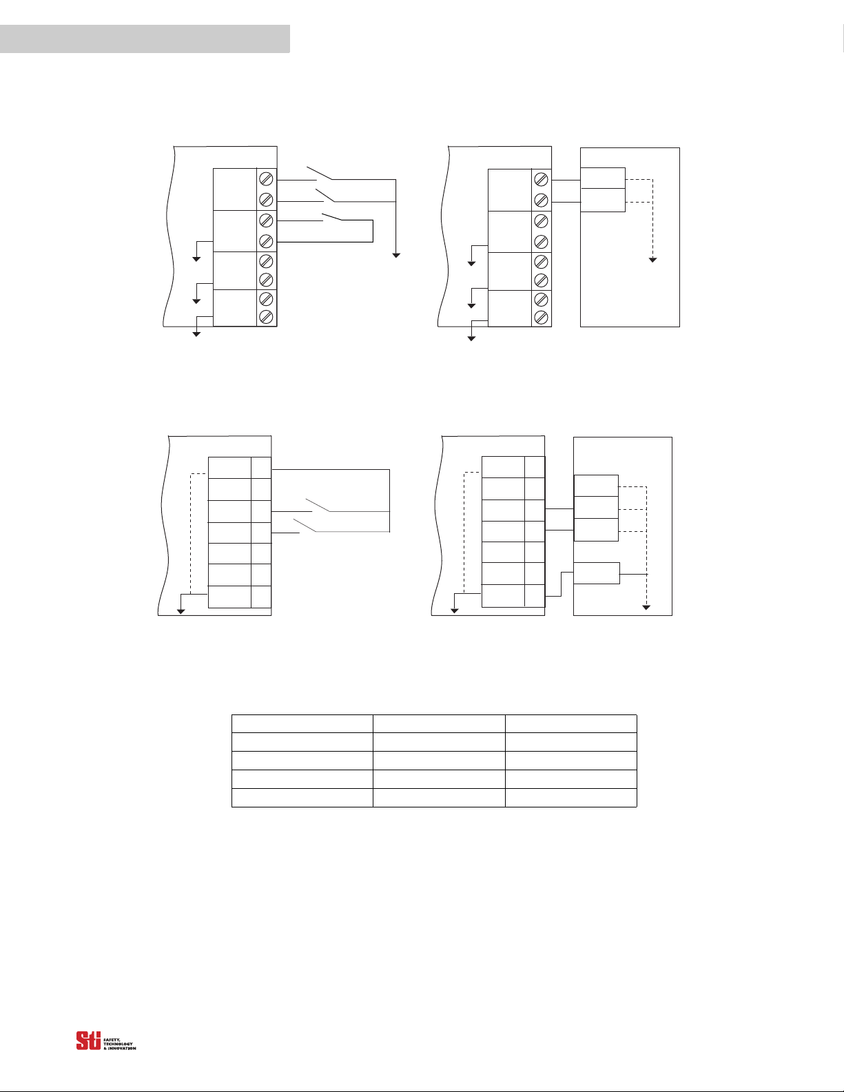
Section 10 -- Connecting To The Machine Control Circuit
. . . . . . . . . . . . . . . . . . . . . . . . . page 32
. . . . . . . . . . . . . . . . . . . . . . . . page 36
. . . . . . . . . . . . . . . . . . . . . . . . . . . . . . page 37
10.1 Din Controller
10.1.1 Connecting to a S
10.1.2 Connecting Via an RM-1 Module
10.1.3 Connecting Via T
10.2 Metal Chassis Controllers
10.2.1 Connecting Via
10.2.2 Connecting Via
. . . . . . . . . . . . . . . . . . . . . . . . . . . . . . . . . . . . . . . . . . . . . . . . . . . . . . page 37
afety Monitoring Device . . . . . . . . . . . . . . . . . . . . . . . . . . page 38
. . . . . . . . . . . . . . . . . . . . . . . . . . . . . . . . . . page 39
wo Force-Guided Relays. . . . . . . . . . . . . . . . . . . . . . . . . . . page 40
. . . . . . . . . . . . . . . . . . . . . . . . . . . . . . . . . . . . . . . . . . . . . page 41
Two Normally Open Relay Safety Outputs . . . . . . . . . . . . . . page 41
One Normally Open One Normally Closed Safety Relay Outputs . . .
. . . . . . . . . . . . . . . . . . . . . . . . . . . . . . . . . . . . . . . . . . . . . . . . . . . . . . . . . . . . . . . . . .
10.2.3 Connecting Solid State Safety Outputs
10.2.4 Connecting Vi
a a Safety Monitoring Device . . . . . . . . . . . . . . . . . . . . . . . . . page 44
Section 11 -- Checkout and Test Procedures
11.1 Checkout Procedur
11.2 Test Procedure
e . . . . . . . . . . . . . . . . . . . . . . . . . . . . . . . . . . . . . . . . . . . . . . . . . page 45
. . . . . . . . . . . . . . . . . . . . . . . . . . . . . . . . . . . . . . . . . . . . . . . . . . . . . . page 45
. . . . . . . . . . . . . . . . . . . . . . . . . . . . . . . . . . . . . . . . . page 45
to Two Force-Guided Relays . . . . . . page 43
11.3 Using the Test Object. . . . . . . . . . . . . . . . . . . . . . . . . . . . . . . . . . . . . . . . . . . . . . . . . page 45
page 42
OMRON SCIENTIFIC TECHNOLOGIES INC.
Fremont CA USA
Tel: 1/888/510-4357 in USA and Canada
3
© OSTI 1209 PN99584-0050 Rev. E
Original Instructions
Page 6

11.4 Test Considerations When Using Exact Channel Select or Floating Blanking. . . . . page 46
Section 12 -- Troubleshooting
Section 13 -- Cleaning
Section 14 -- Specifications and Additional Information
14.1 System Specifications
. . . . . . . . . . . . . . . . . . . . . . . . . . . . . . . . . . . . . . . . . . . . . . . . . . . . page 46
. . . . . . . . . . . . . . . . . . . . . . . . . . . . . . . . . . . . . . . . . . . . . . . . . . . . . . . . . . page 48
. . . . . . . . . . . . . . . . . . . . . . . . . . . . . . . page 49
. . . . . . . . . . . . . . . . . . . . . . . . . . . . . . . . . . . . . . . . . . . . . . . . page 49
14.2 MicroSafe MC4700 Series Dimensions . . . . . . . . . . . . . . . . . . . . . . . . . . . . . . . . . . page 49
14.2.1 MC4700 Series Dimensio
14.2.2 MC4700 Spare Parts
14.3 MicroSafe Flexible MCF4700 Series
14.3.1 MCF4700 Series Dimensions
14.3.2 MCF4700 Spare Parts
ns . . . . . . . . . . . . . . . . . . . . . . . . . . . . . . . . . . . . page 55
. . . . . . . . . . . . . . . . . . . . . . . . . . . . . . . . . . . . . . . . . page 56
. . . . . . . . . . . . . . . . . . . . . . . . . . . . . . . . . . . . page 55
. . . . . . . . . . . . . . . . . . . . . . . . . . . . . . . . . . . page 55
. . . . . . . . . . . . . . . . . . . . . . . . . . . . . . . . . . . . . . . . page 60
14.4 MicroSafe Jointed MCJ4700 Series . . . . . . . . . . . . . . . . . . . . . . . . . . . . . . . . . . . . . page 65
14.4.1 MCJ4700 Segment Dimensions
14.4.2 90° Jointed MicroSafe MCJ47
. . . . . . . . . . . . . . . . . . . . . . . . . . . . . . . . . page 65
00 Dimensions . . . . . . . . . . . . . . . . . . . . . . page 56
14.4.3 Sensor Assembly Instructions . . . . . . . . . . . . . . . . . . . . . . . . . . . . . . . . . . . page 56
14.4.4 Installation
. . . . . . . . . . . . . . . . . . . . . . . . . . . . . . . . . . . . . . . . . . . . . . . . . page 56
14.4.5 Minimum Object Resolution
14.4.6 MCJ4700 Spare Parts. . . . . . . . . . . . . . . . . . . . . . . . . . . . . . . . . . . . . . . . . page 56
14.5 MiniSafe MS4700 Series
14.5.1 MS4700 Dimensions
14.5.2 MS4700 Spare Parts
14.6 MiniSafe Flexible MsF4700 Series
14.6.1 MSF4700 Series Di
14.6.2 MSF4700 Spare
14.7 DIN and LCM NEMA Controllers
Section 15 -- Glossary
15.1 Glossary Definitions
Section 16 -- Others
16.1 Warranty
16.2 Patents
16.3 Trademarks
. . . . . . . . . . . . . . . . . . . . . . . . . . . . . . . . . . . . . . . . . . . . . . . . . . . . . . . . . . page 89
. . . . . . . . . . . . . . . . . . . . . . . . . . . . . . . . . . . . . . . . . . . . . . . . . page 89
. . . . . . . . . . . . . . . . . . . . . . . . . . . . . . . . . . . . . . . . . . . . . . . . . . . . . . . . . . . page 100
. . . . . . . . . . . . . . . . . . . . . . . . . . . . . . . . . . . . . . . . . . . . . . . . . . . . . . . . . page 100
. . . . . . . . . . . . . . . . . . . . . . . . . . . . . . . . . . . . . . . . . . . . . . . . . . . . . . . . . . page 100
. . . . . . . . . . . . . . . . . . . . . . . . . . . . . . . . . . . . . . . . . . . . . . . . . . . . . . . page 100
at Joints . . . . . . . . . . . . . . . . . . . . . . . . . . . . page 56
. . . . . . . . . . . . . . . . . . . . . . . . . . . . . . . . . . . . . . . . . . . . . . page 71
. . . . . . . . . . . . . . . . . . . . . . . . . . . . . . . . . . . . . . . . . . page 71
. . . . . . . . . . . . . . . . . . . . . . . . . . . . . . . . . . . . . . . . . . page 73
. . . . . . . . . . . . . . . . . . . . . . . . . . . . . . . . . . . . . . page 77
mensions . . . . . . . . . . . . . . . . . . . . . . . . . . . . . . . . . . . page 78
Parts. . . . . . . . . . . . . . . . . . . . . . . . . . . . . . . . . . . . . . . . . page 79
. . . . . . . . . . . . . . . . . . . . . . . . . . . . . . . . . . . . . . . page 84
16.4 Repairs
OMRON SCIENTIFIC TECHNOLOGIES INC.
Fremont CA USA
Tel: 1/888/510-4357 in USA and Canada
. . . . . . . . . . . . . . . . . . . . . . . . . . . . . . . . . . . . . . . . . . . . . . . . . . . . . . . . . . page 100
4
© OSTI 1209 PN99584-0050 Rev. E
Original Instructions
Page 7

16.5 Documentation Criteria . . . . . . . . . . . . . . . . . . . . . . . . . . . . . . . . . . . . . . . . . . . . . page 100
. . . . .
Appendix A —Checkout Procedur
e. . . . . . . . . . . . . . . . . . . . . . . . . . . . . . . . . . . . . . . . . . . . . . page 90
A.1 Checkout Procedure Log . . . . . . . . . . . . . . . . . . . . . . . . . . . . . . . . . . . . . . . . . . . . . . page 90
Appendix B —Test Procedur
B.1 Test Procedure Log
Appendix C —DeviceNet Operating Instructions
e . . . . . . . . . . . . . . . . . . . . . . . . . . . . . . . . . . . . . . . . . . . . . . . . . . page 91
. . . . . . . . . . . . . . . . . . . . . . . . . . . . . . . . . . . . . . . . . . . . . . . . . . . page 91
. . . . . . . . . . . . . . . . . . . . . . . . . . . . . . . . . . . page 92
C.1 Introduction . . . . . . . . . . . . . . . . . . . . . . . . . . . . . . . . . . . . . . . . . . . . . . . . . . . . . . . . page 92
C.2 Features
C.2.1 System identification
C.2.2 System status
C.2.3 System Settings
C.2.4 Diagnostic Information
. . . . . . . . . . . . . . . . . . . . . . . . . . . . . . . . . . . . . . . . . . . . . . . . . . . . . . . . . . . page 92
. . . . . . . . . . . . . . . . . . . . . . . . . . . . . . . . . . . . . . . . . . . . page 92
. . . . . . . . . . . . . . . . . . . . . . . . . . . . . . . . . . . . . . . . . . . . . . . . . . page 92
. . . . . . . . . . . . . . . . . . . . . . . . . . . . . . . . . . . . . . . . . . . . . . . . . page 92
. . . . . . . . . . . . . . . . . . . . . . . . . . . . . . . . . . . . . . . . . . page 93
C.3 Basic DeviceNet Network Connections . . . . . . . . . . . . . . . . . . . . . . . . . . . . . . . . . . . page 95
C.4 LCM-2XX series internal D-Net Wire Colors and Pin Outs
C.4.1 Screw Connectors for LCM-2XX series D-Net interface module
C.5 DeviceNet Configuration Switches
. . . . . . . . . . . . . . . . . . . . . . . . . . . . . . . . . . . . . . . page 97
. . . . . . . . . . . . . . . . . . . . page 95
. . . . . . . . . . page 95
C.5.1 Switch Function Selecti
C.6 Quick Disconnect Option
on Description . . . . . . . . . . . . . . . . . . . . . . . . . . . . . . page 98
. . . . . . . . . . . . . . . . . . . . . . . . . . . . . . . . . . . . . . . . . . . . . . page 99
Appendix D —Declaration of Comformity Information . . . . . . . . . . . . . . . . . . . . . . . . . . . . . page 101
OMRON SCIENTIFIC TECHNOLOGIES INC.
Fremont CA USA
Tel: 1/888/510-4357 in USA and Canada
5
© OSTI 1209 PN99584-0050 Rev. E
Original Instructions
Page 8

Table of Figures
Figure 3-1 Accessing the Configuration Switches
Figure 3-2 Accessing the Configuration Switches on
Figure 3-3 4700 Transm
Figure 3-4 DIN Contr
itter and Receiver . . . . . . . . . . . . . . . . . . . . . . . . . . . . . . . . . . . . . . . . page 13
oller Components . . . . . . . . . . . . . . . . . . . . . . . . . . . . . . . . . . . . . . . . . . page 14
on the LCM DIN Controller . . . . . . . . . . . . page 11
the LCM-Metal Chassis Controller . . . . page 12
Figure 3-5 Metal Chassis Controller Components . . . . . . . . . . . . . . . . . . . . . . . . . . . . . . . . . . page 15
Figure 4-1 Functional Flow Diagram
Figure 5-1 Connection Re
commendations for LCM Metal Enclosure. . . . . . . . . . . . . . . . . . . . page 20
. . . . . . . . . . . . . . . . . . . . . . . . . . . . . . . . . . . . . . . . . . . . page 17
Figure 5-2 Connection Recommendations for LCM DIN Box . . . . . . . . . . . . . . . . . . . . . . . . . . page 20
Figure 5-3 Adding Har
Figure 8-1 Safe Mounting Distance
d guarding to Light Curtain when Using Channel Select . . . . . . . . . . . page 23
. . . . . . . . . . . . . . . . . . . . . . . . . . . . . . . . . . . . . . . . . . . . . . page 28
Figure 9-1 Correct Mounting Example with Proper Alignment. . . . . . . . . . . . . . . . . . . . . . . . . page 31
Figure 9-2 Unsafe Mounting Examp
Figure 9-3 Unsafe Mounting Examp
le . . . . . . . . . . . . . . . . . . . . . . . . . . . . . . . . . . . . . . . . . . . . page 31
le . . . . . . . . . . . . . . . . . . . . . . . . . . . . . . . . . . . . . . . . . . . . page 31
Figure 9-4 Worst Case Alignment Example . . . . . . . . . . . . . . . . . . . . . . . . . . . . . . . . . . . . . . . . page 32
Figure 9-5 Minimum Distance from
Figure 9-6 Correct Light Curta
a Reflective Surface as a Function of Range . . . . . . . . . . page 32
in Installation Examples. . . . . . . . . . . . . . . . . . . . . . . . . . . . . . page 34
Figure 9-7 Multiple Light Curtain Installation Configurations. . . . . . . . . . . . . . . . . . . . . . . . . page 35
Figure 9-8 Mounting Orientation
Figure 10-1 Connecting to a Safe
. . . . . . . . . . . . . . . . . . . . . . . . . . . . . . . . . . . . . . . . . . . . . . . . page 35
ty Monitoring Device . . . . . . . . . . . . . . . . . . . . . . . . . . . . . . page 38
Figure 10-2 Connecting via an RM-1 Module . . . . . . . . . . . . . . . . . . . . . . . . . . . . . . . . . . . . . . page 39
Figure 10-3 Connecting Vi
Figure 10-4 Connecting with Tw
Figure 10-5 Connecting with One
Figure 10-6 Connecting with Tw
Figure 10-7 Connecting with Safety
Figure 11-1 Test Object
Figure 14-1 MC4700 Series Dimensional D
Figure 14-2 MicroSafe Flex
Figure 14-3 MicroSafe Jointed MCJ4700
Figure 14-4 90° Jointed Micr
Figure 14-5 Assembly Instructions
Figure 14-6 MS4700 Mechanical Drawin
a Two Force-guided Relays . . . . . . . . . . . . . . . . . . . . . . . . . . . . . . . page 40
o Normally Open Safety Outputs . . . . . . . . . . . . . . . . . . . . . . page 41
Normally Open One Normally Closed Safety Outputs . . . . page 42
o Force Guided Relay Outputs. . . . . . . . . . . . . . . . . . . . . . . . page 43
Monitoring Device . . . . . . . . . . . . . . . . . . . . . . . . . . . . . . page 44
Pattern . . . . . . . . . . . . . . . . . . . . . . . . . . . . . . . . . . . . . . . . . . . . . . . . . page 45
rawing . . . . . . . . . . . . . . . . . . . . . . . . . . . . . . . . . page 55
ible MCF4700 Dimensions . . . . . . . . . . . . . . . . . . . . . . . . . . . . . . page 58
Dimensions . . . . . . . . . . . . . . . . . . . . . . . . . . . . . . . page 65
oSafe MCJ4700 Dimensions . . . . . . . . . . . . . . . . . . . . . . . . . . . . page 66
Steps . . . . . . . . . . . . . . . . . . . . . . . . . . . . . . . . . . . . . . . . . . page 67
g . . . . . . . . . . . . . . . . . . . . . . . . . . . . . . . . . . . . . . . . page 71
Figure 14-7 MiniSafe Flexible MSF4700
OMRON SCIENTIFIC TECHNOLOGIES INC.
Fremont CA USA
Tel: 1/888/510-4357 in USA and Canada
Dimensions. . . . . . . . . . . . . . . . . . . . . . . . . . . . . . . . page 77
6
© OSTI 1209 PN99584-0050 Rev. E
Original Instructions
Page 9

Figure 14-8 DIN Controller Dimension Drawing . . . . . . . . . . . . . . . . . . . . . . . . . . . . . . . . . . . page 84
. . . . .
Figure 14-9 LCM Nema Metal Chassis Contro
ller Dimension Drawing . . . . . . . . . . . . . . . . . page 85
Figure 15-1 DeviceNet Install Location. . . . . . . . . . . . . . . . . . . . . . . . . . . . . . . . . . . . . . . . . . . page 99
Figure 15-2 DevieNet Wi
Figure C-1 Basic Devi
Figure C-2 Pin Outs for
ring with Optional M12 Connector . . . . . . . . . . . . . . . . . . . . . . . . . . page 99
ceNet configuration . . . . . . . . . . . . . . . . . . . . . . . . . . . . . . . . . . . . . . . . page 95
Internal Screw Connectors used internally in the LCM-2XX . . . . . . . page 96
Figure C-3 Pin Outs for Micro_Style Connectors . . . . . . . . . . . . . . . . . . . . . . . . . . . . . . . . . . . page 96
Figure C-4 Pin Outs for
Phoenix-style connectors used in the STI MC4700, LCM-2 interface
. . . . . . . . . . . . . . . . . . . . . . . . . . . . . . . . . . . . . . . . . . . . . . . . . . . . . . . . . . . . . . . . . . . . . . . . . . . page 97
Figure C-5 LCM-2 Power/DeviceNet board . . . . . . . . . . . . . . . . . . . . . . . . . . . . . . . . . . . . . . . page 97
Table of Tables
Table 3-1 System Component Identification for the 4700 Transmitter and Receiver
Table 3-2 System Component Identification for the LCM-1, LCM-2 and LCM-3 Controllers
. . . . . . . . . . . . . . . . . . . . . . . . . . . . . . . . . . . . . . . . . . . . . . . . . . . . . . . . . . . . . . . . . . . . . . . . . . .
Table 4-1 Operating Mode Switch Settings
. . . . . . . . . . . . . . . . . . . . . . . . . . . . . . . . . . . . . . . . page 18
. . . . . . . . page 13
. . . . . . . . .
page 14
Table 5-1 System Response to Exact Channel Select
Table 5-3 System Response to Floating Blanking
Table 5-4 Icon Key for T
Table 5-5 Sample S and D
Table 5-6 Sample S and D
Table 5-7 Sample S and D
Table 5-8 Sample S and D
ables 5-1 and 5-2 . . . . . . . . . . . . . . . . . . . . . . . . . . . . . . . . . . . . . . . . page 21
Factors for 12 mm Resolution Systems. . . . . . . . . . . . . . . . . . . . . page 22
pf
Factors for 14 mm resolution Systems . . . . . . . . . . . . . . . . . . . . . page 22
pf
Factors for 20mm resolution Systems. . . . . . . . . . . . . . . . . . . . . . page 22
pf
Factors for 30 mm resolution Systems . . . . . . . . . . . . . . . . . . . . . page 23
pf
. . . . . . . . . . . . . . . . . . . . . . . . . . . . . . . . . page 19
. . . . . . . . . . . . . . . . . . . . . . . . . . . . . . . . . . . page 21
Table 5-9 Switch Settings, Exact Channel Select and Floating Blanking
Table 6-1 Operational Display Code Summary
Table 6-2 MPCE Switch Setting
s . . . . . . . . . . . . . . . . . . . . . . . . . . . . . . . . . . . . . . . . . . . . . . . . page 26
Table 7-1 Auxiliary Output Operating Mode S
Table 9-1 Color Code/Terminal Number Cr
Table 9-2 Color Code/Terminal Number Cr
Table 12-1 Operational Codes
. . . . . . . . . . . . . . . . . . . . . . . . . . . . . . . . . . . . . . . . . . . . . . . . . . page 46
. . . . . . . . . . . . . . . . . . . . . . . . . . . . . . . . . . . . . page 25
witch Settings . . . . . . . . . . . . . . . . . . . . . . . . . . page 28
oss Reference for DIN Controllers . . . . . . . . . . . . page 32
oss Reference Metal Chassis Controllers . . . . . . . page 32
. . . . . . . . . . . . . . . . . page 24
Table 12-2 DIP Switch Fault Codes
Table 12-3 Safety Output (OSSD) Faults
OMRON SCIENTIFIC TECHNOLOGIES INC.
Fremont CA USA
Tel: 1/888/510-4357 in USA and Canada
. . . . . . . . . . . . . . . . . . . . . . . . . . . . . . . . . . . . . . . . . . . . . page 47
. . . . . . . . . . . . . . . . . . . . . . . . . . . . . . . . . . . . . . . . . . page 47
7
© OSTI 1209 PN99584-0050 Rev. E
Original Instructions
Page 10

Table 12-4 MPCE Faults . . . . . . . . . . . . . . . . . . . . . . . . . . . . . . . . . . . . . . . . . . . . . . . . . . . . . . page 47
Table 12-5 Controller
Table 14-1 Response T
Table 14-2 Response T
Table 14-3 Response
Table 14-4 12mm transm
Table 14-5 14mm,
Table 14-6 MC4700-12
Table 14-7 MC4700-14
Table 14-8 MC4700-20
Table 14-9 MC4700-30
Faults . . . . . . . . . . . . . . . . . . . . . . . . . . . . . . . . . . . . . . . . . . . . . . . . . . . page 48
ime for 12 mm MC4700 and MS4700 . . . . . . . . . . . . . . . . . . . . . . . . . . page 52
ime for 14 mm and 20 mm MC4700 and MS4700 . . . . . . . . . . . . . . . . . page 52
Times for 30 mm MC4700 and MS4700 systems. . . . . . . . . . . . . . . . . . . page 53
itter and Receiver Lengths . . . . . . . . . . . . . . . . . . . . . . . . . . . . . . . . . page 55
20 mm and 30 mmTransmitter and Receiver Lengths . . . . . . . . . . . . . . . . . page 55
Spare Transmitter and Receiver Model Number . . . . . . . . . . . . . . . . . page 56
Spare Transmitter and Receiver Model Number . . . . . . . . . . . . . . . . . page 56
Spare Transmitter and Receiver Model Number . . . . . . . . . . . . . . . . . page 57
Spare Transmitter and Receiver Model Number . . . . . . . . . . . . . . . . . page 57
Table 14-10 MCF4700-12 Dimensions First &
Table 14-11 MCF4700-12 Dimensions L
Table 14-12 MCF4700-14, MCF4700-20
Table 14-13 MCF4700-14, MCF4700-20
ast Segment . . . . . . . . . . . . . . . . . . . . . . . . . . . . . . . . page 59
and MCF4700-30 First and Middle Segment . . . . . page 59
and MCF4700-30 Last Segment . . . . . . . . . . . . . . . page 60
Middle Segment . . . . . . . . . . . . . . . . . . . . . . . page 59
Table 14-14 Transmitter
Table 14-15 MCJ470-12 Dimensions
and Receiver Segments. . . . . . . . . . . . . . . . . . . . . . . . . . . . . . . . . . . . page 60
. . . . . . . . . . . . . . . . . . . . . . . . . . . . . . . . . . . . . . . . . . . . . page 68
Table 14-16 MCJ4700 Joint Resolution (Resolution at the
Table 14-17 Transmitter
Table 14-18 MS4700-12 Dimensions
Table 14-19 MS4700-14 & MS4700-20
Table 14-20 MS4700-30 Dimensions
Table 14-21 Transmitter
Table C-1 Specifications fo
Table C-2 4700 Status Information
Table C-3 I/O Data for Change of S
Table C-4 I/O Data
Table C-5 Configuration Switches for Dev
and Receiver Segments. . . . . . . . . . . . . . . . . . . . . . . . . . . . . . . . . . . . page 68
. . . . . . . . . . . . . . . . . . . . . . . . . . . . . . . . . . . . . . . . . . . . . page 71
Dimensions . . . . . . . . . . . . . . . . . . . . . . . . . . . . . . . . . page 72
. . . . . . . . . . . . . . . . . . . . . . . . . . . . . . . . . . . . . . . . . . . . . page 72
and Receiver Segments. . . . . . . . . . . . . . . . . . . . . . . . . . . . . . . . . . . . page 73
r 4700 System Controller with DeviceNet . . . . . . . . . . . . . . . . . . . page 93
Sent in Response to a poll command . . . . . . . . . . . . . . . . . page 94
tate . . . . . . . . . . . . . . . . . . . . . . . . . . . . . . . . . . . . . . . . . . page 94
. . . . . . . . . . . . . . . . . . . . . . . . . . . . . . . . . . . . . . . . . . . . . . . . . . . . . . . . . . . page 94
ice-Net. . . . . . . . . . . . . . . . . . . . . . . . . . . . . . . . . . . page 98
Corner) . . . . . . . . . . . . . . . . . . . . . page 68
OMRON SCIENTIFIC TECHNOLOGIES INC.
Fremont CA USA
Tel: 1/888/510-4357 in USA and Canada
8
© OSTI 1209 PN99584-0050 Rev. E
Original Instructions
Page 11

. . . . .
▲
!
▲
!
1 I
MPORTANT
S
WARNING! Read and understand this section prior to installing a 4700 system.
A 4700 system is a general purpose presence sensing device designed to guard personnel working
around moving machinery.
Whether a specific machine application and light curtain installation complies with safety regulations
depends on
items are the responsibility of the purchaser, installer and employer.
The employer is responsible for the selection and tra
maintain the machine and its safeguarding systems. A 4700 system should only be installed, verified
and maintained by a
possession of a recognized degree or certificate of professional training, or who, by extensive
knowledge, training or experience, has successfully demonstrated the ability to solve problems relating
to the subject matter and work.” (ANSI B30.2-1983)
To use a 4700 series safety light curtain the following requirements must be met:
— The guarded machine
a press with a full-revolution clutch.
— The guarded machine must not present a hazard from flying parts.
AFETY
the proper application, installation, maintenance and operation of the light curtain. These
W
ARNINGS
ining of personnel to properly install, operate,
qualified person. A qualified person is defined as “a person or persons who, by
must be able to stop anywhere in its cycle. Do not use a safety light curtain on
1
and
— The guarded machine must have a consistent stopp
— Severe smoke, particulate matter and corrosives may degrade the ef
Do not use a 4700 system in this type of environment.
— All applicable governmental and local rules, codes, and regulations must be satisfied. This is the
e
mployer’s responsibility.
— All safety-related machine control elements must be designed so that a alarm in the control logic or
failure of the control circuit does not lead to
— Additional guarding may be required for access to dange
system.
— Perform the OMRON STI test procedure at installation and after
modification to the machine controls, tooling, dies or machine, or the 4700 series system.
— Perform only the test and repair procedures outlined in this manual.
— Follow all procedures in this manual for proper operation of the 4700 series system.
The enforcement of these requirements is beyond the control of OMRON STI. The employer has the
sole re
sponsibility to follow the preceding requirements
requirements specific to his machinery.
WARNING! Despite inherent safe design measures, safeguarding and complementary
protective measures adopted by the user, residual risk m
risks are strictly under the control of the end user and may include severe injury or death.
a failure to danger.
ing time and adequate control m
ficiency of a safety light curtain.
rous areas
and any other procedures, conditions and
ay remain in any installation. Potential
not covered by the 4700 series
maintenance, adjustment, repair or
echanisms.
OMRON SCIENTIFIC TECHNOLOGIES INC.
Fremont CA USA
Tel: 1/888/510-4357 in USA and Canada
9
© OSTI 1209 PN99584-0050 Rev. E
Original Instructions
Page 12

2
2 S
IGNIFICANT
F
EATURES
2.1 STANDARD FEATURES
Individual Beam Indicators
External Device Monitoring (MPCE Monitoring)
Automatic Start Mode
Start Interlock Mode
Start/Restart Interlock Mode
Adjustable Mounting Brackets
Floating Blanking
Exact Channel Select
Two Safety (PNP) Outputs
Auxiliary Output
Start Switch Input Selectable NO or NC
2.2 OPTIONAL FEATURES
Relay Safety Outputs (Metal Chassis Controllers only)
2
DeviceNet
Multi-Channel Select (Non-CE)
OMRON SCIENTIFIC TECHNOLOGIES INC.
Fremont CA USA
Tel: 1/888/510-4357 in USA and Canada
10
© OSTI 1209 PN99584-0050 Rev. E
Original Instructions
Page 13
. . . . .
3 S
I
NDICATORS
YSTEM
A
3.1 A CCESS TO CONFIGURATION SWITCHES
3.1.1 LCM DIN CONTROLLER
CCESS
, C
OMPONENTS
AND
3
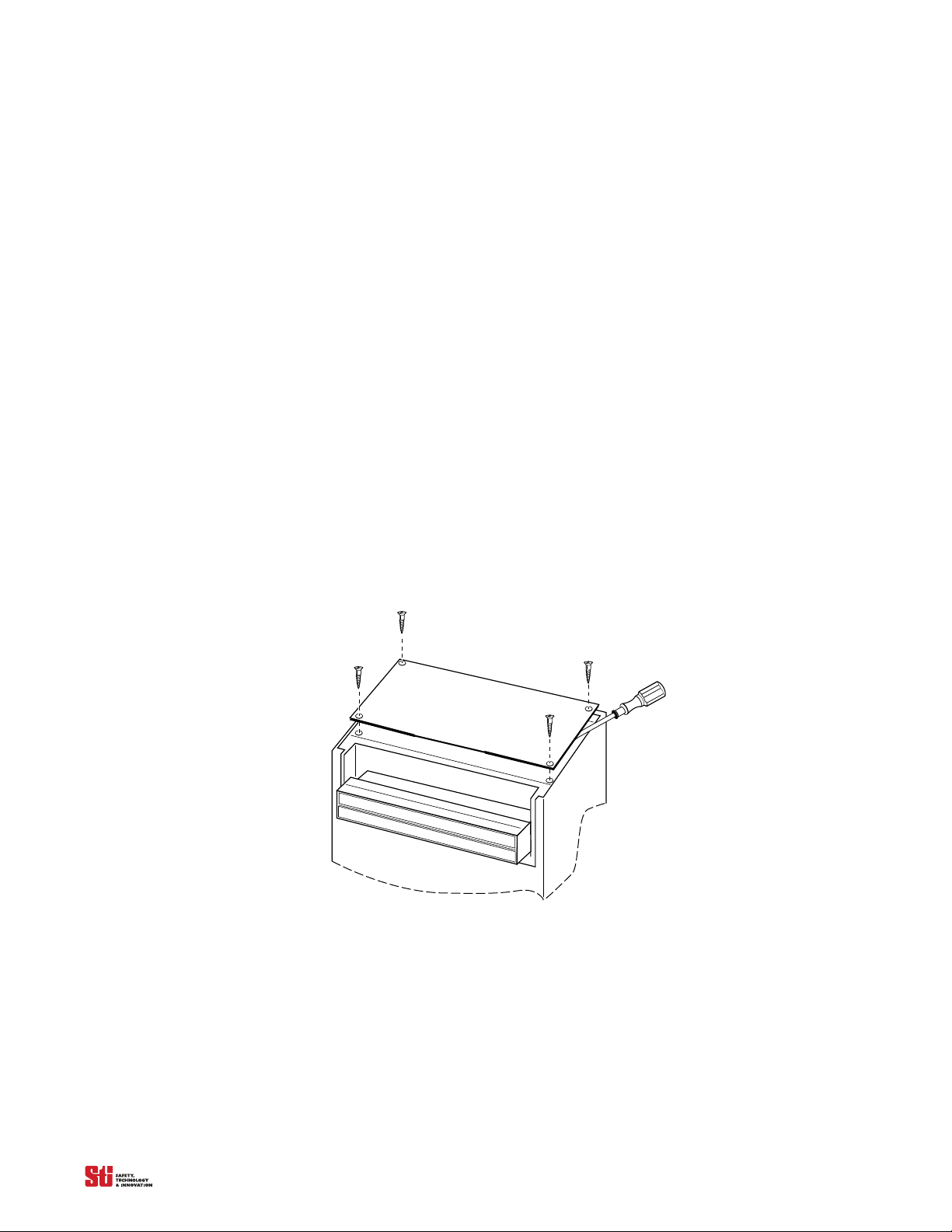
Switches for configuring system features are located under the front cover of the controller. Access to
these switches is gained by the following procedure:
1. Remove the four screws holding the cover in place (see Figure 3-1 for location).
2. Place the blade of a thin flat-blade screwdriver between the cover and the main controller housing
a
nd gently lift the c
removed.
To replace the cover:
1. Correctly position one end and push down on the opposite end to snap it in place.
2. Replace the four screws to properly retain the cover.
over off. See Figure 3-1 for detail. The cover is not hinged and will be completely
Figure 3-1 Accessing the Configuration Switches on the LCM DIN Controller
OMRON SCIENTIFIC TECHNOLOGIES INC.
Fremont CA USA
Tel: 1/888/510-4357 in USA and Canada
11
© OSTI 1209 PN99584-0050 Rev. E
Original Instructions
Page 14
3
STOP
RUN
RUN
START
INTERLOCK
FB/CS
W A R N I N G
Scientific Tec hnologies Inc, Fremont, CA 94555 U. S. A.
R
!
T
o test the light cur tain, use the appropr iate ST Isupplied test object, or proper ly siz ed opaque cyl indri cal
object.
If yo u are using the Channel Select or F loating
Blanki ng features and the object to be ignored does not
completely prevent acc ess to the haz ardous ar ea, ei ther
(1) use a mechanical guard or other means to block
access or (2) increase the minimum safe distance and
use a larger tes t object diameter as explained i n the
Installation and Operating Manual.
1. Di sable the ma chine. Pow er on the l ight cur tain.
2. Ins pect the machine to ensure entry to the
hazardous area is only through the light curtain sensing
field. I f not, additional guardi ng, incl uding mechanical
barriers may be required.
3. Veri fy that the mounting dis tance of the l ight
curtain i s equal to or gr eater than the mini mum safe
distance fr om the hazardous point. Ens ure the operator
is not able to stand undetec ted between the li ght curtai n
and the hazard.
4. Chec k f or exter nal dama ge to the li ght curtai n,
the machine, el ectri cal cabl es and w iri ng.
5. Inter rupt the sensing fi eld with the
test
object t
o check the eff ectiveness of the light c urtain.
Move the test obj ect ins ide the peri meter ( along the top,
Do Not Remove Or Cover This Label
http://www.sti.com1/888/510-4357
STI Label P/N 28621-0010 re
T
EST PROCEDURE
sides and bottom) of the sensing field and up and down
through the center of the sens ing fiel d. Veri fy that the
Red indi cat or i s ON and the G ree n indi cator is OF F w hil e
the test object is anywhere in the sensing field.
watch for any unprotected acces s to the point of ha zard.
6. Star t the machine. Interr upt the sensing f ield
with the test object. The machine shoul d stop
immediately. Never insert the test object into the
dangerous parts of the mac hine! Wi th the machine at
rest, inter rupt the sensi ng fi eld w ith the test obj ect.
that the machine wil l not s tart with the tes t object i n the
sensing field.
7. Ensure the braking and machine stop systems
are working properly in accordance with the machine
manufacturer Õs requirements. I f the machine does no t
stop fast enough, adjust the braking system or increase
the distance fr om the light c urtain to the poi nt hazard.
8. If the saf ety dev ices or machi ne fai l any of these
tests, do not run the mac hine. I mmediately lockout the
machine to prevent i ts use and noti fy the su pervis or
9. If the Channel Select is reprogrammed or
disabled, you must repeat thes e test procedur es.
10. C lose and l ock the li ght curta in contr
enclosu re d oor, if appl i cabl e.
Diagnostic Codes:
00 Normal Operation
01 Normal Operation, waiting for Start signal
02 Normal Operation, Floating Blanking active
03 Normal Operation, Exact Channel Select active
04 Normal Operation, Exact Channel Select and
Floating Blanking active
20 G eneral DIP switch fault
21 Invalid switch setting
22 DIP switch settings changed during operation
23 Invalid Channel Select or MPCE switch settings
30 General Safety Output fault
40 G eneral MPCE fault
41 MPCE open before safety output (OSSD) activation
43 MPCE open when power is applied
50 Internal controller fault
51 Receiver fault
52 Transmitter fault
53 Transmitter and receiver length mismatch or transmitter
and receiver not connected
59 24 VDC power supply fault
Cla sp
PROGRAM
Opti ona l
Keyswitch
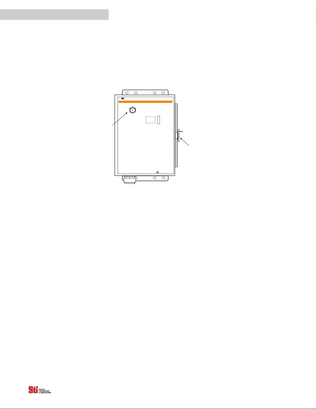
3.1.2 LCM METAL CHASSIS CONTROLLER
Switches for configuring system features are located inside the front cover of the controller. Access to
these switches is gained by the unlocking the clasp on the right-hand side of the controller box.
The Clasp has provisions to accept a user-provided padlock. On
ly a qualified p erson should have
possession of the key to the padlock, or to the optional Program/Start keyswitch.
Figure 3-2 Accessing the Configuration Switches on the LCM-Metal Chassis Controller
OMRON SCIENTIFIC TECHNOLOGIES INC.
Fremont CA USA
Tel: 1/888/510-4357 in USA and Canada
12
© OSTI 1209 PN99584-0050 Rev. E
Original Instructions
Page 15
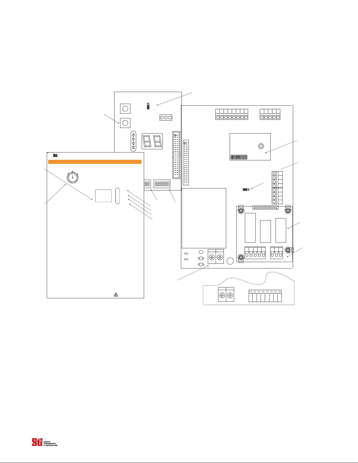
3.2 L OCATION OF THE COMPONENTS AND INDICATORS
2. YEL
4. RED - STOP/BLOCKED
3. GRN - RUN/CLEAR
2. YEL - INTERLOCK
OR CHANNEL SELECT
1. AMBER - FLOATING BLANKING
1. AMBER
4. RED
3. GRN
INDICATORS
LED
RECEIVER
DETECTION
ZONE
TRANSMITTER
MC4700
MC4700
2. YEL
4. RED - STOP/BLOCKED
3. GRN - RUN/CLEAR
2. YEL - INTERLOCK
OR CHANNEL SELECT
1. AMBER - FLOATING BLANKING
1. AMBER
4. RED
3. GRN
INDICATORS
LED
RECEIVER
DETECTION
ZONE
TRANSMITTER
MS4700
MS4700
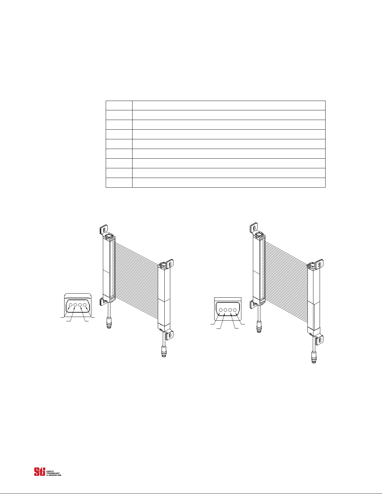
Refer to Figure 3-3, Figure 3-4 and Figure 3-5 for the location of the components and indicators listed
below.
. . . . .
Table 3-1 System Component Identification
for the 4700 Transmitter and Receiver
Chart #
1 RECEIVER
2 Individual Beam Indicators (one for each beam) – Red
3 Channel Select or Floating Blanking Indicator – Amber
4 Interlock or Fault Indicator – Yellow
5 Machine Stop Indicator – Red
6 Machine Run Indicator – Green
7 TRANSMITTER
8 Detection Zone
Figure 3-3 4700 Transmitter and Receiver
OMRON SCIENTIFIC TECHNOLOGIES INC.
Fremont CA USA
Tel: 1/888/510-4357 in USA and Canada
13
© OSTI 1209 PN99584-0050 Rev. E
Original Instructions
Page 16

3
12
11
9
10
15
14
16
13
17
NOTE : F or DeviceNet Option,
LCM-2 Series,
Termina ls 13 to 17
are indica ted below.
131415
DeviceNet
CAN +
DATA H
1617
DATA L
CAN VÐ
13
LCM-1 Series
Fremont, CA, US A
Tel: 510/608-3400, Fax: 510/744-1442
www.sti. com
Scientific Technologies Inc.
OSSD 1
OSSD
RETURN
MPCE
0 VDC
MPCE
RETURN
BLUE
AUX1
OUT
ORANGE
OSSD 2
AUX2
OUT
BLACK
PINK
GRAY
VIOLET
TAN
YELLOW
RED
R
11
12
131415 123457
8
6910
Xmtr
24232221201918 34333231302827 292625
Rcvr
Do not defeat or bypass. Severe injury to
!
WARNING SAFETY DE VICE
personnel could result.
START
RETURN
START
+24 VDC
WHITE
BROWN
Xmtr/RcvrOutput
SHIELD
RS232 MPCE Remote
Power
Not Used
PROG RET
PROGRAM
Not Used
Not Used
FB/CS
Interlock
Stop
Run
Not Used
Not Used
DATA
1617
Not Used
Not Used
18
1
23
19
23
45
Cha nnel S elect
ECS 1
67
PROGRAM
ECS Return
ECS 2
NOTE : For Multi Channel S ele ct Option,
LCM-3 Series,
Terminals 4 to 7
are indica ted on below.
CS Prog
Table 3-2
System Component Identification for the LCM-1, LCM-2 and LCM-3 Controllers
Chart #
4 EXact Channel Select 1 beam
5 EXact Channel Select 2 beams
6 EXact Channel Select 3 beams
7 EXact Channel Select Return
9 Channel Selector Floating Blanking Indicator - Amber
10 Interlock or Alarm Indicator - Yellow
11 Machine Stop Indicator - Red
12 Machine Run Indicator - Green
13 Diagnostic Code Display
14 Switch A
15 Program Button
16 Switch B
17 Removable Terminal Blocks for input and output connections
18 DeviceNet status indicators (optional)
19 Start Switch Type Jumper
20 Relay Board (metal chassis only)
21 Power In (metal chassis only)
22 MPCE Monitoring (metal chassis only)
23 Multi-channel Select terminals
24 Optional Keyswitch
OMRON SCIENTIFIC TECHNOLOGIES INC.
Fremont CA USA
Figure 3-4 DIN Controller Components
14
© OSTI 1209 PN99584-0050 Rev. E
Original Instructions
Tel: 1/888/510-4357 in USA and Canada
Page 17
1 2 3451 2 3 456 7 8
2
1
2
1
MPCE MON
ON
OFF
JMP2
BOARD
DEVICENET
OPTIONAL
-Note: Shown with optional Relay Board.
P2
R44
R45
C8
C9
RV1
MCS
TB5
TX
TB6
RX
J1
J3
TB7
AUX
K2
K1
0SSD2 AUX
TB3
TB1
TB2
PS1
0SSD1
F1
N
L
KEYSWI TCH
J2
N.O.
N.C.
PROGRAM
START
J1
SWA
SWB
STOP
RU N
RUN
STA R T
INTERLOC K
FB/C S
W A R N I N G
Scientific Technologies I nc, Fremont, CA 94555 U. S. A.
R
!
T
o test the light curtain, use the appropriate S TI supplied test object, or properly sized opaque cylindrical
object.
If y ou are using the C hannel Select or Floating
Blanki ng features and the object to be ignored does not
completely prevent access to the hazardous area, either
(1) use a mechanical guard or other means to block
access or (2) increase the minimum safe distance and
use a larger test object diameter as explained in the
In
stallation and Operating Manual.
1. Disable the machine. Power on the light curtain.
2. Inspect the machine to ensure entry to the
hazardous area is only through the light curtain sensing
field. If not, additional guarding, including mechanical
barriers may be required.
3. Verify that the mounting distance of the light
curtain is equal to or greater than the mini mum safe
distance from the hazardous point. E nsure the operator
is not able to stand un
detected between the light curtain
and the hazard.
4. Check for external damage to the light curtain,
the machine, electrical cables and wiri ng.
5. Interrupt the sensing f ield wi th the
test
object t
o check the eff ectiveness of the light curtain.
Move the test object inside the perimeter (along the top,
Do Not Remove Or Cover This Label
http://www.sti.com1/ 888/ 510-4357
ST I L abel P /N 28621- 0010 re
T
EST
P
RO C EDU RE
sides and bottom) of the sensing field and up and down
through the center of the sensing fi eld. V erify that the
Red indicator is ON and the Green indicator is OFF while
the test object i s anywhere in the sensing field.
watch for any unprotected access to the point of hazard.
6. Start the machine. Interrupt the sensing field
with the test o bject. T he machi ne s hould stop
immediatel y. N ever ins ert the tes
t object into the
dangerous parts of the machine! With the machine at
rest, interrupt the sensing field with the test object.
that the machine will not start with the test object in the
sensing field.
7. E nsure the braking and machine stop systems
are working properly in accordance with the machine
manufacturerÕs r equirements. I f the machine does not
stop fast enough, adjust the braking system or i ncrease
the distance from the light curtain to the
point hazard.
8. If the safety devices or machine fail any of these
tests, do not run the machine. I mmediately lockout the
machine to prevent its use and notif y the supervisor
9. If the C hannel S elect is reprogrammed or
disabled, you must repeat these test procedures.
10. Close and lock the light curta in contr
enclosure door, if applicable.
Dia g no sti c C od es :
00 Normal O pera tion
01 Normal O pera tion, waiting for S tart signal
02 Normal Opera
tion, Floating Blanking a ctive
03 Normal O pera tion, Exact C hannel Select active
04 Normal O pera tion, Exact C hannel Select and
Floating Blanking active
20 General DIP switch fault
21 Invalid switch setting
22 DIP switch settings changed during operation
23 Invalid Channel Select or MPC E switch settings
30 General Safety O utput fa ult
40 General MPCE fault
41 MPCE open before safety output (OSSD) activation
43 MPCE open when power is applied
5
0 Internal controller fault
51 Receiver fault
52 Transmitter fault
53 Transmitter and receiver length mismatch or transmitter
and receiver not connected
59 24 VDC power supply fa ult
Inside Front Lid of the metal chassis controller
19
15
16
14
18
17
20
21
13
9
10
11
12
23
TB4
TB1
Shown with DC Solid State Configuration
Note: For Solid State Configuration, JMP2 and
PS1 are not available.
+
_
22
PR O G RA M
24
2
1
2
1
PROG
START
MPCE
. . . . .
OMRON SCIENTIFIC TECHNOLOGIES INC.
Fremont CA USA
Tel: 1/888/510-4357 in USA and Canada
Figure 3-5 Metal Chassis Controller Components
15
© OSTI 1209 PN99584-0050 Rev. E
Original Instructions
Page 18

4
☛☛
4 S
YSTEM
O
PERATION
The 4700 system is a microprocessor-controlled, infrared transmitted-beam safety light curtain. The
system consists of a receiver assembly and a transmitter assembly. Quick disconnect cables link the
controller to the transmitter and receiver.
The safety light curtain is often used where personnel protection is
include mechanical power presses, robotic work cells, filter presses, injection molders, food
processing equipment and automated assembly equipment.
required. Typical applic
4.1 OPERATING STATES
The operating condition of a 4700 system is described in terms of states. The following operating
states exist for the 4700 system.
4.1.1 MACHINE RUN
The two system safety outputs are in the ON state, the green machine run indicator is lit, and the
auxiliary output is in a state consistent with its configuration. See
machine is allowed to operate. Pressing and releasing the start button
4.1.2 MACHINE STOP
The two system safety outputs are in the OFF state, the red machine stop indicator is lit, and the
auxiliary output is in a state consistent with its configuration. See section
protected machine is not allowed to operate. Press and releasing the start switch has no effect.
Section 7 on page 27. The protected
has no effect.
Section 7 on page 27. The
4
ations
4.1.3 INTERLOCK
The two system safety outputs are in the OFF state, the red machine stop indicator and yellow
interlock indicator are lit. The auxiliary output is in a state consistent with its configuration. See
Section 7 on page 27. The interlock state does not allow the protected machine to operate until the
detection zone is clear of obstructions and the start button is pressed and released.
4.1.4 ALARM
The two system safety outputs are in the OFF state, the red machine stop indicator is lit, the yellow
interlock indicator is flashing, and the auxiliary output is in the OFF state. The alarm state does not
allow the protected machine to operate. The primary difference between alarm and interlock is that the
4700 system will remain in the alarm state until power is recycled or the start switch is pressed and
released and the system has run a self-test.
4.2 OPERATING MODES
System operating modes determine the start-up and operating behavior of the 4700 system. Operating
mode definitions rely on the operating states presented above. Operating mode selection is performed
via configuration switches under the front cover of the controller.
NOTE! If internal faults are detected by the 4700 system during power-up or operation, it will enter
the alarm state with its safety outputs in the OFF state.
4.2.1 AUTOMATIC START
The 4700 system will power-up with its safety outputs OFF, and perform system initialization and self
tests. The 4700 system will enter the machine run state if no obstructions are present in the detection
zone. In this state, when an object is sensed entering the detection zone, the 4700 system will change
OMRON SCIENTIFIC TECHNOLOGIES INC.
Fremont CA USA
Tel: 1/888/510-4357 in USA and Canada
16
© OSTI 1209 PN99584-0050 Rev. E
Original Instructions
Page 19
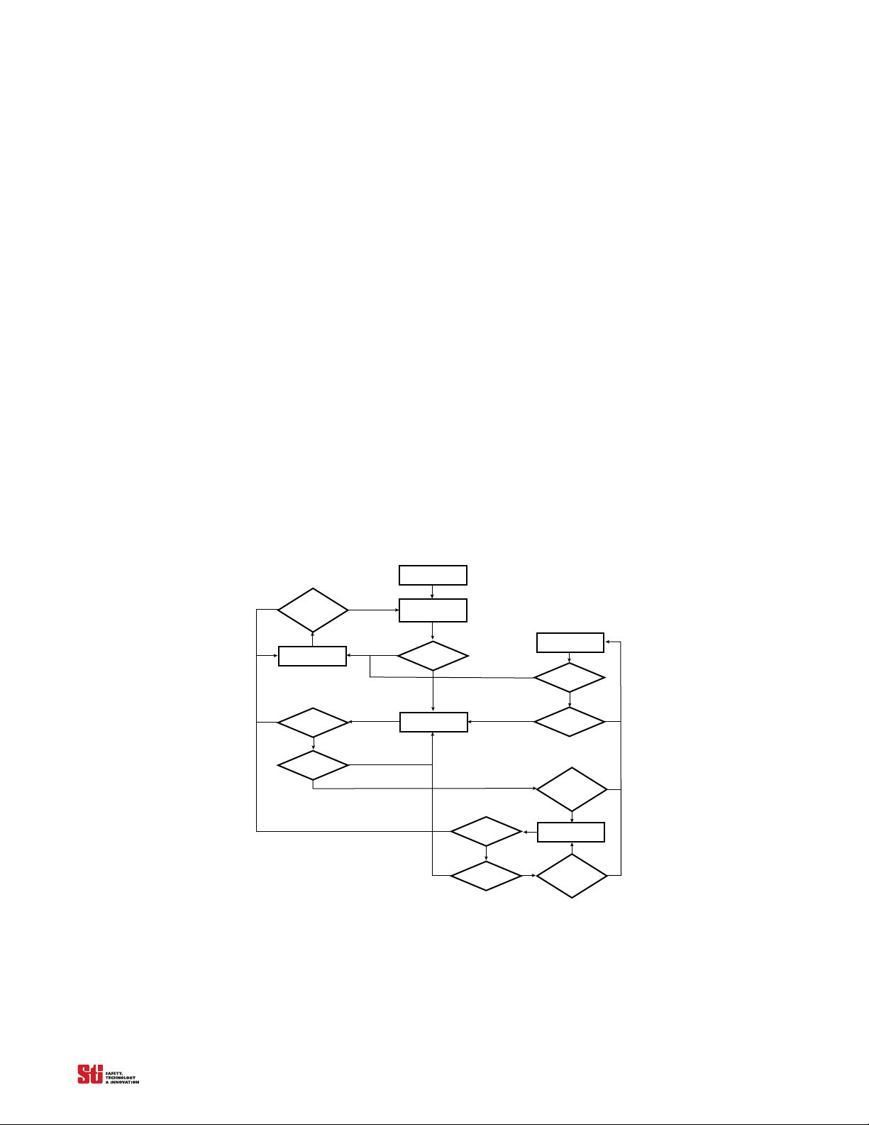
from machine run to machine stop and remain in this state until the obstruction is removed. Once the
Power-Up
Power-On
Self-Test
Failure
Mach ine S top
Start
Pressed &
Released
Fault
Failure
Beam
Cleared
Mach ine ru n
Failure
Beam
blocked
Start/
Restart
Interlock
Interlock
Failure
Beam
Blocked
Start
Pressed &
Released
No
Yes
No
No
No
No
No
No
YesYes
YesYes
Yes
Yes
Yes
Yes
Yes
Yes
detection zone is clear, the 4700 system will automatically change from machine stop to machine run.
4.2.2 START INTERLOCK
The 4700 system will power-up with its safety outputs OFF and perform system initialization and selftests. If no obstructions are detected in the protected zone, (or an exact channel select pattern satisfied),
the 4700 system enters the interlock state. To enter the machine run state, the detection zone must be
clear (or an exact channel select pattern satisfied), and then the operator must press and release the start
switch. In the machine run state, when an object is sensed entering the detection zone the 4700 system
will change from machine run to machine stop. Once the detection zone is clear, the 4700 system will
automatically change from machine stop to machine run.
4.2.3 START/RESTART INTERLOCK
The 4700 system will power-up with its safety outputs OFF, and, if no faults are detected, enter the
interlock state. To enter the machine run state, the detection zone must be clear (or an exact channel
select pattern satisfied), and then the operator must press and release the start switch. In the machine
run state, when an object is sensed entering the detection zone the 4700 will change from machine run
to interlock. The 4700 system will remain in the interlock state even after the obstruction is removed
from the detection zone. To enter the machine run state, the operator must press and release the start
switch. If any obstruction is present in the detection zone when the start switch is pressed and released,
the 4700 will remain in the interlock state.
. . . . .
NOTE! The definitions above mention a start switch. See Section 10–“Connecting to the Machine
Control Circuit” for wiring of the start switch.
OMRON SCIENTIFIC TECHNOLOGIES INC.
Fremont CA USA
Tel: 1/888/510-4357 in USA and Canada
Figure 4-1 Functional Flow Diagram
17
© OSTI 1209 PN99584-0050 Rev. E
Original Instructions
Page 20

5
▲
!
▲
!
▲
!
4.3 OPERATING MODE SELECTION
Operating mode is selected by setting positions 1 and 2 of Switches A and B, located under the
controller cover. Refer to Table 4-1. Any mismatch between the settings of Switch A and B will result
in an alarm condition. In addition, if the configuration switch settings change
will enter the alarm state with the safety outputs off.
Warning! Disconnect power before accessing the controller assembly.
Table 4-1 Operating Mode Switch Settings
SWITCH A SWITCH B
OPERATING MODE 1 2 1 2
Automatic Start (default setting) CLOSED/ON CLOSED/ON CLOSED/ON CLOSED/ON
Start interlock OPEN/OFF CLOSED/ON OPEN/OFF CLOSED/ON
Start/Restart interlock OPEN/OFF OPEN/OFF OPEN/OFF OPEN/OFF
Not Allowed CLOSED/ON OPEN/OFF CLOSED/ON OPEN/OFF
while the system is on, it
4.4 START SWITCH TYPE SELECTION
The type of Start switch (Normally Open or Normally Closed) used by the 4700 system is selectable
by a jumper located under the controller cover. Refer to Figure 3-4 DIN Controller
Figure 3-5 Metal Chassis Controller Components. Placin
selects a Normally Closed Start Switch. Placing the jumper between 2 and 3 selects a Normally Open
Start switch.
g the jumper between Pins 1 and 2 of JMP 1
Components and
18
type of Start
or Floating Blanking, to avoid unexpected areas where the
selected and used, (i.e. jump
to personnel. Exact Channel
Additional Guarding When Using Exact Channel
m controller should be inst
prevent access to the hazardous
gramming may be inadvertently
er between Pins 1
alled in an
increase.
© OSTI 1209 PN99584-0050 Rev. E
Original Instructions
5
Note: If there is a mismatch between the
and 2 and Normally Open Start Switch used) the switch must be pressed and released twice before
the system will enter a Run state.
5 D
ETECTION
OMRON SCIENTIFIC TECHNOLOGIES INC.
Fremont CA USA
Tel: 1/888/510-4357 in USA and Canada
O
PTIONS
Warning! Use of Exact Channel Select and/or Floating Blanking will make the 4700 system less sensitive to
objects in the detection zone. Improper use of either can result in severe injury
Select may require a hard barrier guard (see Section 5.8
Select
), Exact Channel Select or Floating Blanking requires an increase in the safety distance. Read the
following section carefully.
- To prevent unauthorized modification of the detection zone. The syste
enclosure with supervisor-controlled access.
- If the object to be ignored by the Channel Selected beams does not completely
area, then either use a hard guard or other means to block access or increase the minimum safe distance as
required by the proper formula.
- Any beams which are not in alignment at the time of Channel Select pro
deselected. Use the OMRON STI Test Procedure to verify the correct configuration.
- Floating Blanking increases the minimum safety distance therefore test object size will
- After programming or activating Channel Select
system may not sense an intrusion into the detection zone, use a proper size test object to perform the OMRON
STI Test Procedure.
Page 21
5.1 E XACT CHANNEL SELECT (ECS)
ECS disables selected, fixed areas of the detection zone by masking off specific, fixed beam locations.
ECS is helpful when stationary objects such as tooling and fixtures permanently obstruct a portion of
the detection zone.
. . . . .
Channel Select
s
Statu
Channel 1
Channel 2
Channel 3
Channel 4
Channel 5...
System Response
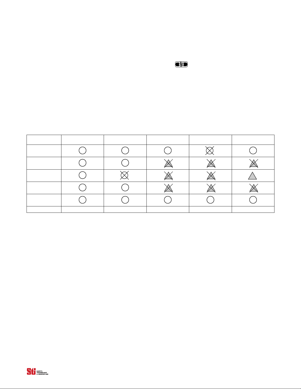
ECS requires that any portion of the detection zone which is block
ed remain blocked
. If the obstruction
is removed the 4700 system will enter a machine stop state. When selecting channels to be masked, one
channel must remain unblocked. A channel is defined as one transmitter/receiver pair or “beam”.
See Table 5-1, System Response to Exact Channel Select for a diagram of 4700 system response during
operation with ECS active.
Table 5-1
Exact Channel Select
Inactive
machine run machine stop machine run machine stop machine stop
System Response to Exact Channel Select
Exact Channel Select
Inactive
Exact Channel Select
Active
Exact Channel Select
Active
Exact Channel Select
5.2 M ULTI CHANNEL SELECT (MCS)
MCS stores up to four patterns of selected beams. Just as the ECS disables selected, fixed areas of the
detection zone by masking off specific, fixed beam locations, the MCS can be programmed to store
four different patterns. MCS is helpful when a machine requires multiple setups where stationary
objects such as tooling, fixtures, or material frequently obstruct a portion of the detection zone. Access
and programming is performed using a PLC or switch inputs. The suggested logic patterns for
identification of the stored program are in Table 5-2 on page 20. Refer to drawings Figure 5-1 and
Figure 5-2 for connection recommendations.
Active
OMRON SCIENTIFIC TECHNOLOGIES INC.
Fremont CA USA
Tel: 1/888/510-4357 in USA and Canada
19
© OSTI 1209 PN99584-0050 Rev. E
Original Instructions
Page 22
LCM-3XX
SW2
SW1
0vdc
LCM-3XX
Out 1
Out 2
PLC
TB7
Switch Selection Connection
PLC Selection Connection
1
2
MPCE
Start
Prog
MCS
1
2
1
2
1
2
TB7
1
2
MPCE
Start
Prog
MCS
1
2
1
2
1
2
5
RET
ECS 2
ECS 1
LCM-3
SW2
SW1
LCM-3
Out 1
Out 0
0vdc ref.
PLC
Switch Selection Connection PLC Selection Connection
+24 VDC
Earth
0 vdc
7
6
5
4
3
2
1
RET
ECS 2
ECS 1
+24 VDC
Earth
0 vdc
7
6
5
4
3
2
1
Figure 5-1 Connection Recommendations for LCM Metal Enclosure
Figure 5-2 Connection Recommendations for LCM DIN Box
Switch Switch 2 Switch 1
Pattern1 0 0
Pattern 2 0 1
Pattern 3 1 0
Pattern 4 1 1
Note: 0 = Open, 1 = Closed.
Table 5-2 Switches for Multi Channel Select
OMRON SCIENTIFIC TECHNOLOGIES INC.
Fremont CA USA
Tel: 1/888/510-4357 in USA and Canada
20
© OSTI 1209 PN99584-0050 Rev. E
Original Instructions
Page 23
5.3 F LOATING BLANKING
▲
!
Up to two channels can be disabled at any location in the detection zone without the 4700 system going
to the machine stop state. The disabled channels are not fixed at a single location but “float” through
the detection zone.
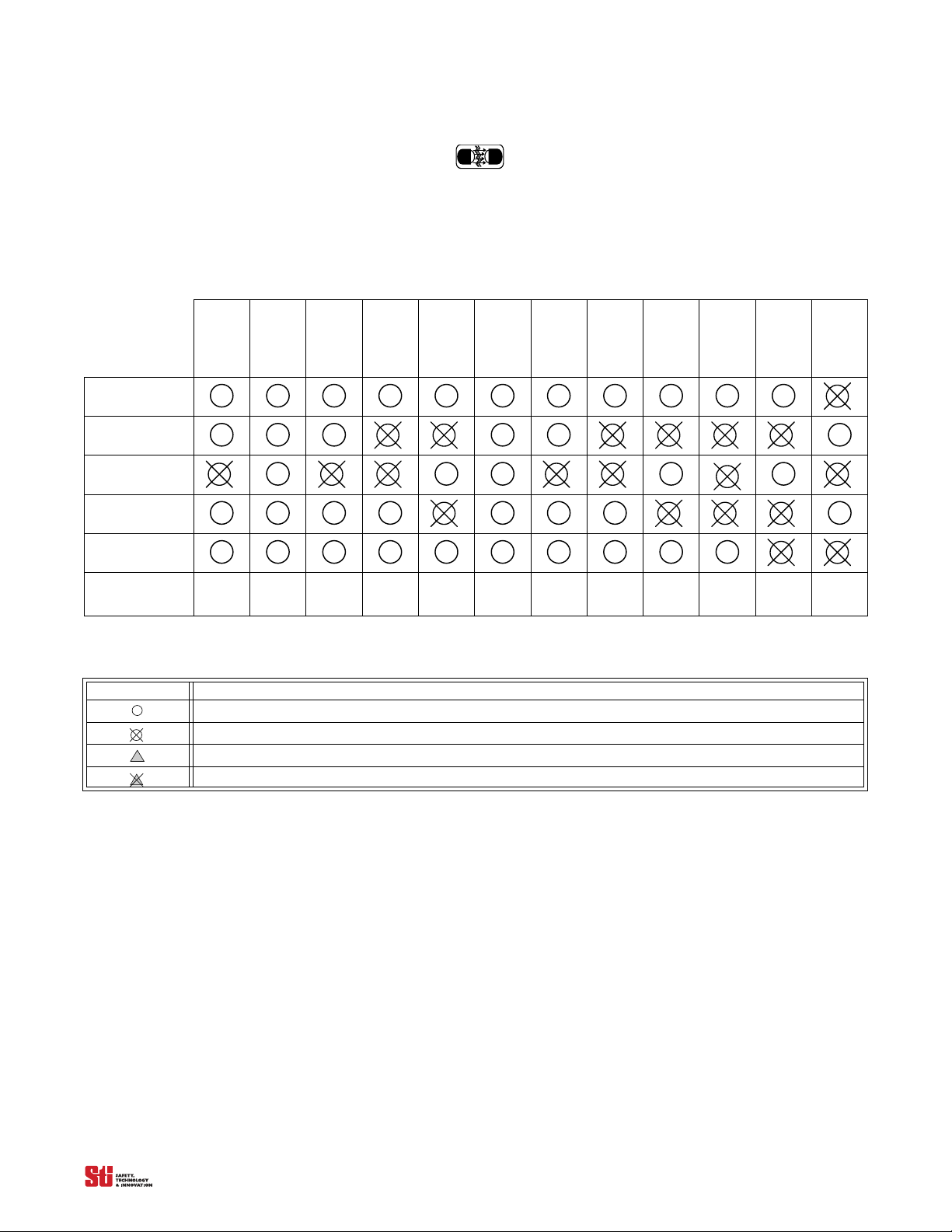
See Table 5-3 for a diagram of 4700 system response during operation with Floating Blanking active.
. . . . .
Blanking
Channel 1
Channel 2
Channel 3
Channel 4
Channel 5...
System Response
Symbol Description
Floating
Inactive
1
Exception
machine
stop
Table 5-3
Chann
loati
F
Blanking
Active
Exceptions
machine
run
Table 5-4
System Response to Floating Blanking
1
0
el
Channel
ng
F
Blanking
Exception
1
loating
Active
1
machine
run
1
Channel
loating
F
Blanking
Active
2
Exceptions
machine
stop
1
Channel
loating
F
Blanking
Active
2
Exceptions
machine
stop
Icon Key for Tables 5-1 and 5-2
2
Channel
ting
Floa
Blanking
Active
0
Exceptions
machine
run
2
Channel
oating
Fl
Blanking
Active
1
Exception
machine
run
Optical channel is not blocked.
Optical channel is blocked.
Optical channel is selected by Exact Channel Select.
Optical channel is selected by Exact Channel Select and is blocked.
2
Channel
loating
F
Blanking
Active
2
Exceptions
machine
run
2
Channel
loating
F
Blanking
Active
2
Exceptions
machine
run
2
Channel
loating
F
Blanking
Active
3
Exceptions
machine
stop
2
Channel
loating
F
Blanking
Active
3
Exceptions
machine
stop
2
Channel
loating
F
Blanking
Active
3
Exceptions
machine
stop
5.4 U SING EXACT CHANNEL SELECT WITH FLOATING BLANKING
Warning! Using Exact Channel Select with Floating Blanking is an advanced feature. All situations which
may occur to the 4700 system detection zone must be carefully considered.
objects in the detection zone. The safety distance must be increased. Failure to do so may cause serious injury.
When both Exact Channel Select and Floating Blanking are selected, the floating channels are allowed
to occur anywhere within the detection zone, even within the area selected by Exact Channel Select. In
these areas, a channel that should normally be blocked is allowed to be clear.
5.4.1 THE EFFECT OF EXACT CHANNEL SELECT AND FLOATING BLANKING ON MINIMUM OBJECT RESOLUTION
When Exact Channel Select and/or Floating Blanking is active, the safety distance is affected. Exact
Channel Select and Floating Blanking desensitize the light curtain and increase the size of the
minimum object detected. The increase is equal to the channel spacing distance for each channel that is
disabled.
• A 4700 system with 12 mm minimum object resolution and one channel disabled has a minimum object
sensitivity of:
12 mm + 6.25 mm = 18.25 mm (0.72 inches).
OMRON SCIENTIFIC TECHNOLOGIES INC.
Fremont CA USA
Tel: 1/888/510-4357 in USA and Canada
21
The 4700 system is less sensitive to
© OSTI 1209 PN99584-0050 Rev. E
Original Instructions
Page 24

5
• A 4700 system with 12 mm minimum object resolution and two channels disabled has a minimum object
sensitivity of:
12 mm + 6.25 mm + 6.25 mm = 24.5 mm (0.96 inches).
If the size of the object detected by the 4700 system increases, the minimum safe distance must
increase. Use the minimum object sensitivity given in T
determine the new figure to use when computing the safety distance.
able 5-5, Table 5-6, Table 5-7 & Table 5-8 to
Table 5-5
Select and/or Floating Blanking
Sample S and Dpf Factors for 12 mm Resolution Systems
Total Number of Beams
Disabled by Exact Channel
None 12 mm (0.47 inches) 0.67 inches (16.96 mm)
1 Beam 19 mm (0.75 inches) 1.61 inches (40.93 mm)
2 Beams 26 mm (1.02 inches) 2.53 inches (64.25 mm)
3 Beams 33 mm (1.30 inches) 3.48 inches (88.43 mm)
4 Beams 40 mm (1.57 inches) 4.40 inches (111.75 mm)
5 Beams 47 mm (1.85 inches) 5.35 inches (135.93 mm)
etc...
Table 5-6
Select and/or Floating Blanking
Sample S and Dpf Factors for 14 mm resolution Systems
Total Number of Beams
Disabled by Exact Channel
None 14 mm (0.55 inches) 0.9 inches (24 mm)
1 Beam 25 mm (0.98 inches) 2.4 inches (61 mm)
2 Beams 36 mm (1.42 inches) 3.9 inches (99 mm)
3 Beams 47 mm (1.85 inches) 5.4 inches (136 mm)
4 Beams 58 mm (2.28 inches) 6.8 inches (173 mm)
5 Beams 69 mm (2.72 inches) 8.3 inches (211 mm)
etc...
Minimum
Object Resolution S
Minimum
Object Resolution S
Depth Penetration Factor, Dpf
for use with
Depth Penetration Factor, Dpf
for use with
ANSI Formula (Dpf
= 3.4 (S-.276) inches)
ANSI Formula (Dpf
= 3.4 (S-.276) inches)
Table 5-7
Select and/or Floating Blanking
Sample S and Dpf Factors for 20mm resolution Systems
Total Number of Beams
Disabled by Exact Channel
None 20 mm (0.79 inches) 1.75 inches (44.45 mm)
1 Beam 31 mm (1.22 inches) 3.21 inches (81.53 mm)
2 Beams 42 mm (1.65 inches) 4.60 inches (118.96 mm)
3 Beams 53 mm (2.09 inches) 6.16 inches (156.86 mm)
4 Beams 64 mm (2.52 inches) 7.63 inches (193.76 mm)
5 Beams 75 mm (2.95 inches) 9.1 inches (231.16 mm)
etc...
OMRON SCIENTIFIC TECHNOLOGIES INC.
Fremont CA USA
Tel: 1/888/510-4357 in USA and Canada
Object Resolution S
22
Minimum
Depth Penetration Factor, Dpf
r use with
fo
ANSI Formula (Dpf
= 3.4 (S-.276) inches)
© OSTI 1209 PN99584-0050 Rev. E
Original Instructions
Page 25
. . . . .
Light
Detection Zone
Light
Channel S elec t Area
Obstruction
▲
!
Table 5-8
Select and/or Floating Blanking
Sample S and Dpf Factors for 30 mm resolution Systems
Total Number of Beams
Disabled by Exact Channel
None 30 mm (1.18 inches) 3.07 inches (78.0 mm)
1 Beam 52 mm (2.05 inches) 6.03 inches (153.2 mm)
2 Beams 74 mm (2.01 inches) 8.96 inches (227.6 mm)
3 Beams 96 mm (3.78 inches) 11.91 inches (302.5 mm)
4 Beams 118 mm (4.65 inches) 14.87 inches (377.7 mm)
5 Beams 140 mm (5.51 inches)‘ 17.80 inches (452.0 mm)
etc...
Minimum
Object Resolution S
Depth Penetration Factor, Dpf
for use with ANSI Formula
= 3.4 (S-.276) inches)
(Dpf
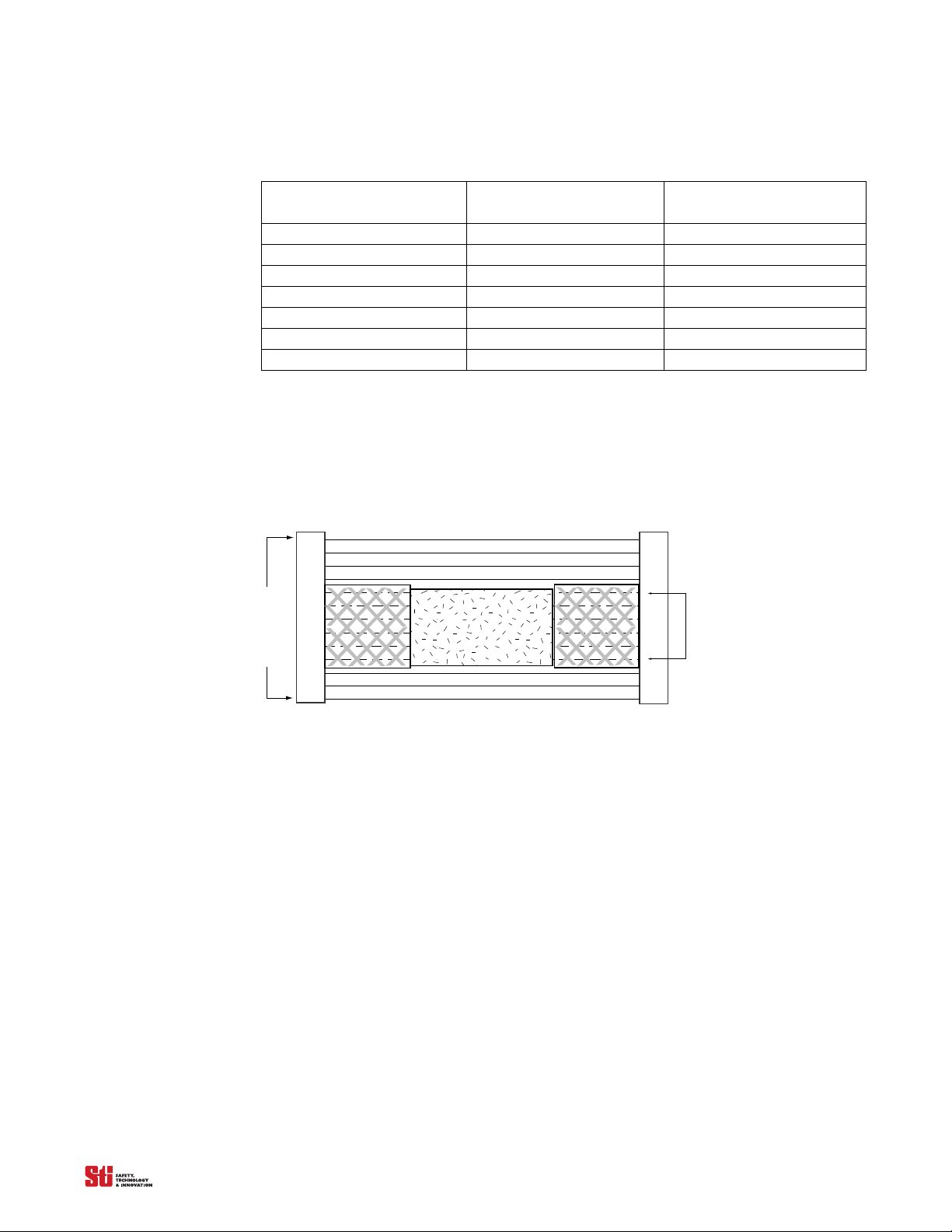
Hard guarding refers to mechanical barriers such as sheet or expanded metal, etc. See Figure 5-3
Adding Hard guarding to Light Curtain when Using Channel Select for an example.
Floating Blanking changes the resolution (object size) of the 4700 system and will require different
mounting distance
.
Figure 5-3 Adding Hard guarding to Light Curtain when Using Channel Select
5.5 A CTIVATING AND PROGRAMMING EXACT CHANNEL SELECT
Warning! To prevent unauthorized modification of the sense field, the system controller should be installed in
an enclosure with supervisor-controlled access.
Exact Channel Select is activated by setting position 4 of Switches A and B, located under the
controller cover. Refer to Figure 3-1. Any mismatch between the settings of the switches will result in
a alarm condition.
To program an ECS pattern, the 4700 system must be in the machine stop state. An ECS pattern is
stored
by blocking th
e appropriate area of the detection zone and pressing, then releasing the program
button (See Figure 3-4 and Figure 3-5 for locations). The MCS works the same as the ECS except in
addition to blocking the appropriate area of the detection
zone, an four position binary
switch or PLC
or two SPST switches are needed to differentiate the four possible pattern.
5.6 MCS PROGRAMING
1. Ensure that power is supplied to the controller, and that the light curtain is green and showing all
beams are clear. The display should read “00”.
2. Set position 4 of switches A and B to the closed position a
OMRON SCIENTIFIC TECHNOLOGIES INC.
Fremont CA USA
Tel: 1/888/510-4357 in USA and Canada
“03”.
23
nd press “Start”,
the display should red
© OSTI 1209 PN99584-0050 Rev. E
Original Instructions
Page 26
5
3. Set the Pattern select inputs, see Table 5-2 Switches for Multi Channel Select.
4. Place the desired object in field (block beams) and press the “program” button, the display should
read “01”.
5. Push the “start” button, and the display should read “03”. The light curtain will enter the Machine
Run
state.
add more patterns (a total of eight possible) Set the Pattern select inputs to another program the
6. To
display will read
7. To change from one pattern to another, change the ECS inputs to the desired program and push the
sta
rt button.
“27”, press the start button and continue to step 4. Repeat steps 4 and 5.
The 4700 syste
mode. The Start button m
m will then enter the interlock or machine stop condition, regardless of the operating
ay be pressed-and-released or power may be cycled to enter the machine run
state. Subsequent power cycles will result in operation in accordance with the configured operating
mode.
A new ECS pattern is recorded when the system is
in the machine stop
state with no alarms, the
configuration switches are correctly set, and the Program button is pressed and released. If the
configuration switches are subsequently set to disable ECS, the stored ECS pattern is cleared.
NOTE! Replace controller cover after changing system configuration. See
Section 3.1.2 on page 12 for details.
and
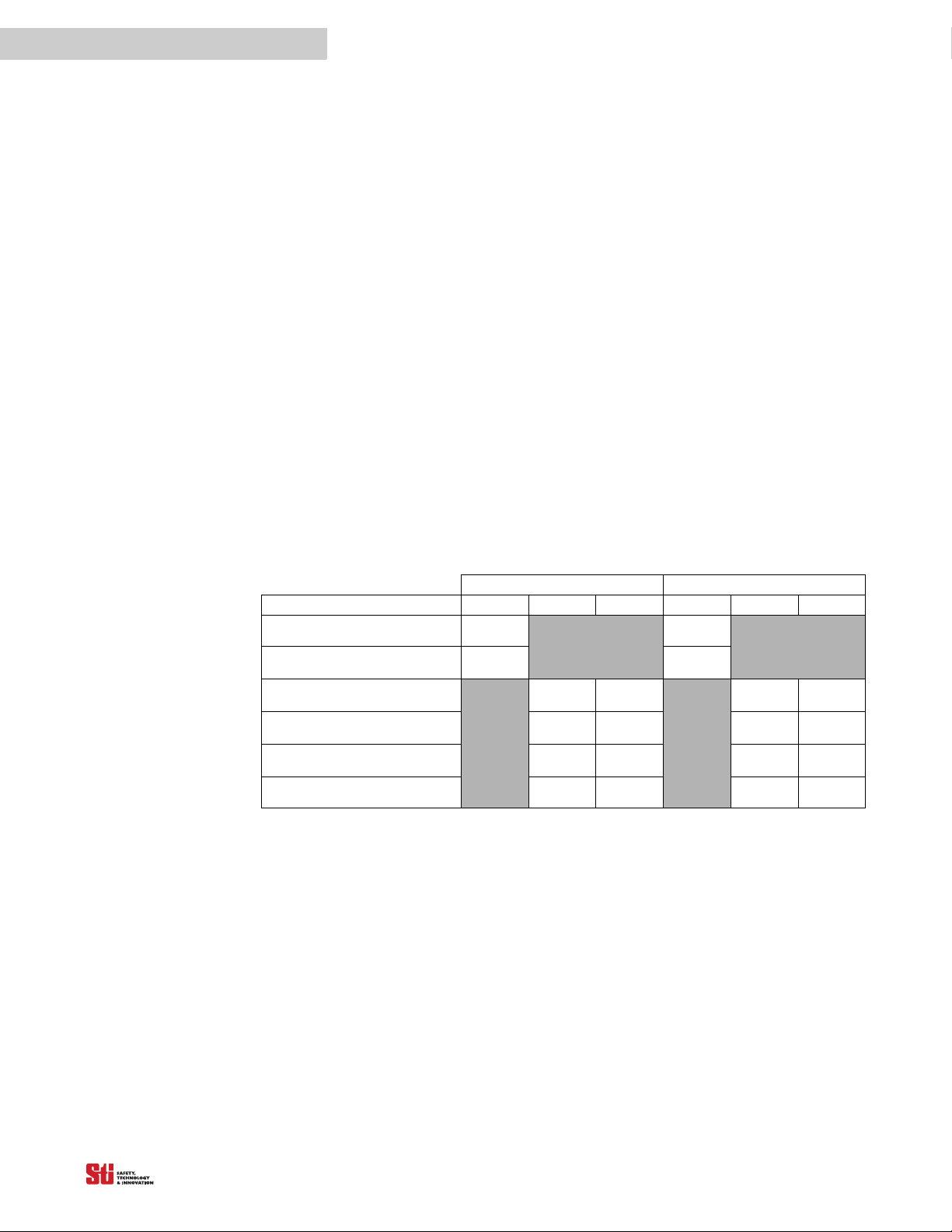
SWITCH A SWITCH B
OPERATING MODE 4 5 6 4 5 6
Exact Channel Select Active CLOSED
Exact Channel Select Inactive
(default setting)
One-channel Floating Blanking
Two-channel Floating Blanking
Floating Blanking Inactive (default
Not Allowed – alarm Condition CLOSED
Table 5-9 Switch Settings, Exact Channel Select and Floating Blanking
Active
Active
setting)
/ON
OPEN
/OFF
CLOSED
/ON
OPEN
/OFF
OPEN
/OFF
/ON
OPEN
/OFF
CLOSED
/ON
OPEN
/OFF
CLOSED
/ON
Section 3.1.1 on page 11
CLOSED
/ON
OPEN
/OFF
CLOSED
/ON
OPEN
/OFF
OPEN
/OFF
CLOSED
/ON
OPEN
/OFF
CLOSED
/ON
OPEN
/OFF
CLOSED
/ON
5.7 ACTIVATING FLOATING BLANKING
Floating Blanking (either one- or two- beam) is activated by setting positions 5 and 6 of Switches A
and B located under the controller cover. Refer to . Any mismatch between the settings of Switches
will result in an alarm condition. Use of the program button is not required.
5.8 ADDITIONAL GUARDING WHEN USING EXACT CHANNEL SELECT
Exact Channel Select creates “holes” in the detection zone. These “holes” are required for certain
applications. If an obstruction does not completely fill these “holes” one of two actions will need to
happen: (Refer to Figure 5-3 Adding Hard guarding
1. The safe mounting distance will need to be increased to account for the larger opening in the curtain.
2. The area not filled by an obstruction must be guarded, typically by some method of hard guarding.
OMRON SCIENTIFIC TECHNOLOGIES INC.
Fremont CA USA
Tel: 1/888/510-4357 in USA and Canada
24
to Light Curtain when Using Channel Select).
© OSTI 1209 PN99584-0050 Rev. E
Original Instructions
Page 27

. . . . .
6 D
IAGNOSTIC AND
T
EST
F
EATURES
6.1. DIAGNOSTIC DISPLAY
A two-digit numeric display on the front of the controller indicates system status. The table below
provides the operating mode codes. A full listing of diagnostic codes can be found in Section 12
Troubleshooting.
Table 6-1
Operational Display Code Summary
Display Code Description
00 Normal Operation
01 Waiting for Start or Program Input
02 Normal Operation
Floating Blanking Active
03 Normal Operation
Channel Select Active
04 Normal Operation
Floating Blanking and Channel Select Active
6.2 I NDIVIDUAL BEAM INDICATORS
The 4700 system has a visible, red Individual Beam Indicator (IBI), adjacent to each infrared beam.
These IBI’s are located on the receiver. The IBI will light when the infrared beam fails to meet the
conditions necessary for the 4700 system to remain in the machine run state.
6
IBI’s are not a safety critical component. An IBI failure will not cause an alarm condition and the 4700
system w
ill cont
inue to operate.
6.3 MACHINE PRIMARY CONTROL ELEMENT (MPCE) MONITORING
MPCE monitoring is an important safety function. It monitors the 4700 system interface to the guarded
machine and checks to ensure that the control elements are responding correctly to the light curtain and
to detect any inconsistency between the two machine MPCE.
Connections for MPCE monitoring are made at the controller on terminals 10 and 11 for the DIN
c
ontroller and on TB7 te
Section 10 Connecting To The Machine Control Circuit. On power-up, the 4700 system looks for an
MPCE
closed condition. If this is found, it will enter a state consistent with the sele
mode. When the 4700 system enables its safety outputs, it monitors the MPCE for a closed-to-open
transition. This transition must occur within 300 ms or the 4700 system considers the MPCE faulted.
The 4700 system will then enter an alarm state. Additionally, if the MPCE connections are incorrectly
wired, the 4700 will enter an alarm state.
Upon entering a machine stop state, the MPCE input must close within 300 ms of the safety output
switchin
using the configuration switches located in the controller.
NOTE! When MPCE is not active, place a jumper between the terminals MPCE and MPCE RTN for
the DIN controller (or place a jumper between terminals 1 and 2 of TB7 for the Solid State Output
Version of the metal chassis controller).
g or the system will
rminals 1 and 2 for the metal chassis controller. For a detailed diagram, see
cted operating
enter the alarm state. The ability to disable MPCE monitoring is provided
OMRON SCIENTIFIC TECHNOLOGIES INC.
Fremont CA USA
Tel: 1/888/510-4357 in USA and Canada
25
© OSTI 1209 PN99584-0050 Rev. E
Original Instructions
Page 28

6
6.3.1 ACTIVATING AND DEACTIVATING MPCE MONITORING
(on Din Controller and Metal Chassis Solid State Version)
MPCE monitoring is activated by setting position 3 of Switches A and B located under the controller
cover. Refer to
alarm condition.
Table 6-2. Any mismatch between the settings of Switches A and B will result in an
Table 6-2 MPCE Switch Settings
MPCE MONITORING 3 3
Active OPEN/OFF OPEN/OFF
Not Active (default setting) CLOSED/ON CLOSED/ON
SWITCH A SWITCH B
NOTE! Replace controller cover and retention screws after changing system configuration. See
Section 3.1.1 on page 11 and Section 3.1.2 on page 12 for details.
6.3.2 ACTIVATING AND D EACTIVATING MPCE MONITORING ON THE M ETAL CHASSIS CONTROLLER-RELAY OUTPUT
ERSION
V
MPCE monitoring is activated by setting Jumper 2 in the ON position located on the main controller
board of the metal chassis controllers. Position 3 of the dipswitch does not affect the operation of
Relay version controller.
6.4. STATUS INDICATOR LIGHTS
The following status indicator lights are found on both the receiver and the controller.
6.4.1 SAFETY OUTPUT STATUS
When the 4700 system is in the machine run state, the green indicator LEDs on the receiver and
controller illuminate, indicating that the safety outputs are ON.
6.4.2 INTERLOCK STATUS
When the 4700 system enters an interlock state, the yellow interlock and red LEDs on the receiver and
controller are continuously illuminated.
6.4.3 ALARM STATUS
When the 4700 system enters an alarm state, the yellow LEDs on the receiver and controller flash
periodically. Additionally, a code indicating the type of fault is displayed on the two-digit diagnostic
display located on the controller. Error codes are defined in Section 12 Troubleshooting.
6.4.4 EXACT CHANNEL SELECT AND FLOATING BLANKING STATUS
When Exact Channel Select and/or Floating Blanking is active, the amber LEDs on the receiver and
controller are illuminated.
OMRON SCIENTIFIC TECHNOLOGIES INC.
Fremont CA USA
Tel: 1/888/510-4357 in USA and Canada
26
© OSTI 1209 PN99584-0050 Rev. E
Original Instructions
Page 29

. . . . .
▲
!
7 O
UTPUTS
7.1 SAFETY OUTPUTS
7.1.1 DIN CONTROLLER AND METAL CHASSIS SOLID STATE VERSION
The 4700 system supplies two independent PNP-type, safety outputs to provide Run/Stop signals to
the guarded machine. In the machine Run state, the safety outputs are electrically conducting and
source 650 milliamps of current at 24 VDC. In the Machine Stop state, the outputs are not electrically
conducting.
WARNING! This product is designed for use on a 24 VDC, negative ground (protective earth) electrical
system only. Never connect the 4700 system to a positive ground (p
ground (protective earth) wiring scheme, certain simultaneous shorts of both safety outputs may not be detected
and the guarded machine may not stop resulting is severe operator injury.
7.1.2 METAL CHASSIS CONTROLLER – RELAY OUTPUT VERSION
The 4700 system supplies 1 N.O. and 1 N.C/N.O. dry relay contacts, safety outputs to provide
Run/Stop signals to the guarded machine. In the Run state the N.O. contacts are closed and will
conduct the supplied voltage. In the Machine Stop state, the N.O. contacts are open. The N.C. contact
will open in a Run state and close in a Stop state.
rotective earth) system. With a positive
7.2. AUXILIARY OUTPUTS
7.2.1 DIN CONTROLLER AND METAL CHASSIS SOLID STATE VERSION
Two auxiliary outputs are provided. Auxiliary output AUX1 OUT is NPN and sinks up to 100 mA to
system ground when in the on condition. Auxiliary output AUX2 OUT is PNP and sources 250 mA at
24 VDC when in the on condition.
7
7.2.2 METAL CHASSIS CONTROLLER - RELAY OUTPUT VERSION
N.O./N.C. auxiliary outputs are provided. These outputs are intended for light curtain Status
indication. The auxiliary output is user configurable for Alarm mode and Follow mode.
7.2.3 AUXILIARY OUTPUT OPERATING MODES
The auxiliary outputs can be set to enter an ON condition either when:
•The safety outputs are in the machine run state (Follow Mode), or
•The 4700 system enters an alarm state (Alarm Mode).
The auxiliary output operating mode is selected by setting position 7
under the controller cover. Refer to Table 7-1. Any mismatch between the settings of the switches will
result in an alarm conditions.
OMRON SCIENTIFIC TECHNOLOGIES INC.
Fremont CA USA
Tel: 1/888/510-4357 in USA and Canada
27
of Switches A and B located
© OSTI 1209 PN99584-0050 Rev. E
Original Instructions
Page 30
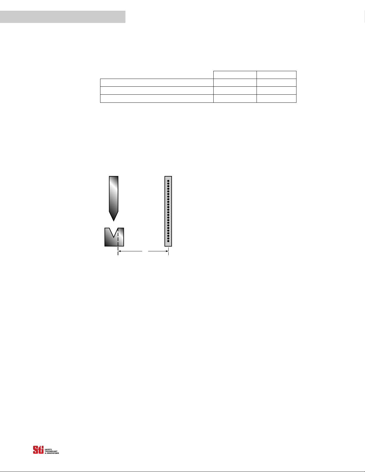
8
Light Curtain
D
s
Ds is the minimum safe distance
between the light curtain sens ing
field and the point of operation
hazard (pinch point).
▲
!
8 S
AFE
Table 7-1
Auxiliary Output Operating Mode 7 7
Auxiliary Outputs on in RUN (Follow) state OPEN/OFF OPEN/OFF
Auxiliary Outputs on in FAULT (Alarm) state CLOSED/ON CLOSED/ON
NOTE! Replace controller cover and retention screws after changing system configuration. See
Section 3.1 for details.
M
OUNTING
Auxiliary Output Operating Mode Switch Settings
SWITCH A SWITCH B
D
ISTANCE
WARNING! Never install a 4700 system without regard to
the safety distance. If the 4700 system is mounted too
point of operation hazard, the machine may not stop in time to
prevent an operator injury.
A 4700 system must be mounted far enough from the machine
danger zone so the machine will stop before a hand or other
body part reaches the hazardous area. This distance is called
the safety distance. It is a calculated number based on a
formula. See Figure 8-1 Safe Mou
illustration of the safety distance.
nting Di
8
close to the
stance for an
OMRON SCIENTIFIC TECHNOLOGIES INC.
Fremont CA USA
Tel: 1/888/510-4357 in USA and Canada
Regardless of the calculated distance, a 4700 system should
never be mounted closer to the p
allowed by Table 0-10 in OSHA 1910.217.
Figure 8-1 Safe Mounting Distance
oint of operation hazard than
8.1 US SAFE DISTANCE FORMULAS
In the United States two formulas exist to properly determine the safety distance. STI recommends the
formula provided by the American National Standards Institute (ANSI) which incorporates additional
factors when compared to the formula required by OSHA.
The ANSI formula given below is for a normal approach to the light curtain.
D
= K x (Ts + Tc + Tr + Tbm) + D
s
Where:
= minimum safety distance, in inches, between the 4700 system detection zone and the nearest point
D
s
of operation hazard.
K =
hand speed constant in inches per second. The ANSI standard value is 63 inches/second which
assumes the operator starts a hand motion
B11.19-1990, “The value of the hand speed constant, K, has been determined by various studies and
although these studies indicate speeds of 63 in./sec. to over 100 in./sec., they are not considered
conclusive determinations. The user should consider all factors, including the physical ability of the
operator, when determining the value of K to be used.”
T
= the stop time of the press (or machine) in seconds, measured from the final de-energized control
s
element. Measured at maximum closing velocity.
pf
toward the point of operation from rest. According to ANSI
28
© OSTI 1209 PN99584-0050 Rev. E
Original Instructions
Page 31

Tc = the response time, in seconds, of the press or machine control circuit to activate the machine’s
▲
!
brake.
. . . . .
NOTE! T
T
r
+ Tc is usually measured together by a stop time measuring device.
s
= the response time of the 4700 system, in seconds. This response time is given in Table 14-1, Table
14-2 and Table 14-3.
WARNING! When using a STI RM-1 with the 4700, add 0.008 seconds to the response times stated in Table
14-1
, Table 14-2 and Table 14-3.
Tbm = the additional stopping time, in seconds, allowed by the brake performance monitor before it
detects stop time deterioration.
The T
monitor. Therefore, T
NOTE! If the guarded machine is not equipped with a stop time performance monitor, a percentage
factor allows consideration for brake wear, adding extra stop time allowed by the brake
bm
= Brake monitor set point - (Ts + Tc).
bm
increase factor should be applied to the stop time of the machine to allow for braking system wear.
Contact your machine manufacturer for information.
D
= This is related to the minimum object sensitivity of the 4700 system. By knowing the minimum
pf
object sensitivity, S, of the 4700 system, D
is read directly from Table 5-5, Table 5-6, Table 5-7 or
pf
Table 5-8.
For a 4700 system with 12 mm minimum object resolution and without Exact Channel Select or
Floating Blanking active:
S =
0.47 inches (12 mm) and D
= 0.67 inches (16.96 mm)
pf
For a 4700 system with 20 mm minimum object resolution and without Exact Channel Select or
Floating Blanking active:
S = 0.79
inches (20 mm) and D
= 1.75 inches (44.45 mm)
pf
8.2 E UROPEAN SAFETY DISTANCE FORMULAS
The following discussion is based on standard EN999 and applies to light curtains used in industrial
environments.
8.2.1 SAFETY DISTANCE FORMULA FOR SYSTEMS WITH A MINIMUM OBJECT RESOLUTION OF 40 MM OR LESS
When the minimum object resolution of the system is 40 mm or less, use the following formula:
S = (K x T) + C
where:
S = the minimum distance in millimeters, from the danger zone to the detection point, line, plane or
zone.
K = 2000 mm/s
T
= the overall system stopping performance in seconds.
T = t
+ t
1
2
t1 = response time of the safety light curtain in seconds. This response time is given in Table 14-
1, Table 14-2 and Table 14-3.
t
= maximum stopping time of the machine in seconds.
2
C = 8(d-14 mm), but not less than zero.
OMRON SCIENTIFIC TECHNOLOGIES INC.
Fremont CA USA
Tel: 1/888/510-4357 in USA and Canada
29
© OSTI 1209 PN99584-0050 Rev. E
Original Instructions
Page 32

8
d = the minimum object detection of the 4700 in millimeters.
i.e.:
S = (2000 mm/s x T) + 8(d – 14 mm)
This formula applies for all minimum distances of S up to and including 500 mm. The minimum value
of S shal
If S is found to be greater than 500 mm using the formula above, then the formula below can be used.
In this c
S = (1600 mm/s x T) + 8(d – 14 mm)
8.2.2 SAFETY DISTANCE FORMULA FOR SYSTEMS WITH A MINIMUM OBJECT RESOLUTION GREATER THAN 40 MM
When the minimum object resolution of the system is greater than 40 mm, use the following formula:
S = (K x T) + C
where:
S = the minimum distance in millimeters, from the danger zone to the detection point, line, plane or
zone.
l not be less than 100 mm.
ase the minimum value of S shall not be less than 500 mm.
K = 16
00 mm/s
T = the overall system stopping performance in seconds.
T = t
+ t
1
2
t1 = response time of the safety light curtain in seconds. This response time is given in Table 14-1,
Table 14-2 and Table 14-3.
t2 = maximum stopping time of the machine is seconds.
C = 850 mm.
i.e.:
S = (1600 mm/s x T) + 850 mm
8.2.3 FACTORS AFFECTING THE SAFETY DISTANCE FORMULA
When light curtains are used for machine initiation, their minimum object resolution must be 30 mm or
smaller (based on EN999, other standards may vary). In this case the formula given in 8.2.1 Safety
Distance Formula
for Systems with a Minimum Object Resolution of 40 mm or Less applies except that
the minimum distance S shall be greater than 150 mm. For parallel approach the formula C becomes:
C = 1200mm – (0.4 x H), but not less than 850 mm.
H = the height of the detection zone above the floor in mm.
OMRON SCIENTIFIC TECHNOLOGIES INC.
Fremont CA USA
Tel: 1/888/510-4357 in USA and Canada
30
© OSTI 1209 PN99584-0050 Rev. E
Original Instructions
Page 33

. . . . .
Tra ns mitte r
Receiver
Approach direction
Central beam
L ight be am in terrupted
d
Reflective Surface
Interruption
a
Beam Angle, a
Operating Range, R
Tra nsm itter
Receiver
Approach direction
Central beam
L ight be am in terrupted
d
Reflective Surface
Perimeter of danger area
Reflection
Interruption
a
Beam Angle, a
Receiver
Reflective Surface
Perimter of danger area
Reflection
Interruption
a
Sensing Field
Tr ans m itter
9 I
NSTALLATION
9.1 R EFLECTIVE SURFACE INTERFERENCE
A reflective surface adjacent to the detection zone can deflect the optical beam and may cause an
obstruction in the zone not to be detected. (See Figure 9-2 and Figure 9-3.) The reflective surface may
be part of the machine, mechanical guard or workpiec
between the reflective object and the center line of the 4700 system detection zone. The Test Procedure
(Appendix B)
Figure 9-1 Correct Mounting Example with Proper Alignment
The interruption is clearly detected. The reflective object is outside of the beam angle
must be used to test for this condition.
e. Therefore,
9
a minimum distance (d) must exist
OMRON SCIENTIFIC TECHNOLOGIES INC.
Fremont CA USA
Tel: 1/888/510-4357 in USA and Canada
Figure 9-2 Unsafe Mounting Example
The interruption is not detected because of the reflection. The reflective object is inside the beam angle.
Figure 9-3 Unsafe Mounting Example
31
© OSTI 1209 PN99584-0050 Rev. E
Original Instructions
Page 34

9
Trans mitter
Receiver
Beam Angle, a
d
Reflective Surface
Operating Range, R
a
a
Perimeter of danger area
0
100
300
500
700
900
2m
4m
6m
8m
10m
12m
14m
16m
Minimum distance
Range (m)
18m
20m
1.1m
1.3m
0.3m
d(mm)
Interruption is not detected because of the reflection. Reflective surface interference may also appear
above and below the sensing field.
Figure 9-4 Worst Case Alignment Example
This example shows the minimum distance from the reflective surface, d, to one side of the beam
center line.
Figure 9-5 Minimum Distance from a Reflective Surface as a Function of Range
9.2. CONNECTING TRANSMITTER AND RECEIVER TO CONTROLLER
9.2.1 CABLE ASSEMBLIES
Receiver cable connectors are color-coded red and transmitter cable connectors are color-coded black.
9.2.2 CABLE CONNECTIONS
Transmitter and receiver connections are made at terminal positions 23 through 34. Insert and secure
the appropriate color conductor in the numbered position. Positions 26, 27, and 28 accept identically
colored conductors from both the transmitter and receiver. For ease of installation, the terminal block
can be removed from the controller. See the table below for a color code/terminal number crossreference.
Table 9-1 Color Code/Terminal Number Cross Reference for DIN Controllers
OMRON SCIENTIFIC TECHNOLOGIES INC.
Fremont CA USA
Tel: 1/888/510-4357 in USA and Canada
Terminal Number Component Conductor Color
23 Transmitter Orange
24 Transmitter Blue
25 Transmitter Black
26 Transmitter and Receiver Shield
32
© OSTI 1209 PN99584-0050 Rev. E
Original Instructions
Page 35

Terminal Number Component Conductor Color
27 Transmitter and Receiver White
28 Transmitter and Receiver Brown
29 Receiver Pink
30 Receiver Violet
31 Receiver Gray
32 Receiver Ta n
33 Receiver Yellow
34 Receiver Red
. . . . .
Table 9-2 Color Code/Terminal Number Cross Reference
TB5 Terminals Component Conductor Color
1 Receiver White
2 Receiver Brown
3 Receiver Ta n
4 Receiver Yell ow
5 Receiver Red
6 Receiver Grey
7 Receiver Violet
8 Receiver Pink
TB6 Terminals Component Conductor Color
1 Transmitter White
2 Transmitter Brown
3 Transmitter Blue
4 Transmitter Black
5 Transmitter Orange
Metal Chassis Controllers
OMRON SCIENTIFIC TECHNOLOGIES INC.
Fremont CA USA
Tel: 1/888/510-4357 in USA and Canada
33
© OSTI 1209 PN99584-0050 Rev. E
Original Instructions
Page 36

9
Hazard
Zone
D
s
LIGHT CURTAIN
Mechanical
Barrier
Supplemental
Guarding
Example
Supplemental
Guarding
Supplemental
Guardi ng
9.3 GENERAL CONSIDERATIONS
9.3.1 ADDITIONAL GUARDING
Areas of access to the point of hazardous operation not guarded by the 4700 system must be protected
by suitable means such as a fixed barrier guard, an interlocked guard or a safety mat. See Figure 9-6.
S uppl eme nta l
Guardi ng
Supplemental
Guardi ng
Figure 9-6 Correct Light Curtain Installation Examples
OMRON SCIENTIFIC TECHNOLOGIES INC.
Fremont CA USA
Tel: 1/888/510-4357 in USA and Canada
34
© OSTI 1209 PN99584-0050 Rev. E
Original Instructions
Page 37

9.3.2 INSTALLATION OF MULTIPLE SYSTEMS
Machine 1
T
Receiver T
Receiver
ra ns mitter
ra ns mitter
PREFERRED INSTALLATION
An alternating receiver to
tra ns mi tter orientation
is sugges ted.
Tran sm itter
Receiver
Tran sm itter
Receiver
Machine 1 Mach ine 2
PREFERRED INSTALLATION
The receivers are mounted
back to back .
Mach ine 1
Tran sm itter
Tran sm itter
Receiver
Mach ine 2
Receiver
NOT RE COMMENDED INSTALLATION
This arrangement may be s ubject
to in ter fer enc e betw een the two
light curtains .
Beam starts here
Beam starts here
Corner access
and grey
shaded area
needs
mechanical
guar ding.
Corner access
and grey
shaded area
needs
mechanical
guar ding.
Corner access
and grey
shaded area
needs
mechanical
guar ding.
Corner access
and grey
shaded area
needs
mechanical
guar ding.
Beam starts here
Beam starts here
STI recommends overlapping the light curtains in
order to have better coverage.
When two or more 4700 systems are mounted in close proximity and in alignment with each other,
precautions should be taken to avoid one curtain interfering with another. This can be corrected by
mounting the transmitters and receivers back-to-back or stacked. See Figure 9-7 for reference.
. . . . .
Figure 9-7 Multiple Light Curtain Installation Configurations
Figure 9-8 Mounting Orientation
OMRON SCIENTIFIC TECHNOLOGIES INC.
Fremont CA USA
Tel: 1/888/510-4357 in USA and Canada
35
© OSTI 1209 PN99584-0050 Rev. E
Original Instructions
Page 38

9
9.3.3 DETECTION ZONE
The 4700 detection zone is delineated by the inside edge of the transmitter and receiver endcaps. The
area outside these marks is not protected. Position the 4700 so that it is only possible to access the
danger point through the detection zone.
9.3.4 MARKING MINIMUM OBJECT RESOLUTION
Serial number labels on the transmitter and receiver indicate three possible minimum object
resolutions. During installation, use a permanent marker to obscure the object resolutions not set. This
will depend on whether no floating blanking, 1-beam or 2-beam floating blanking is set. See
on page 23 for information.
9.3.5 ALIGNMENT
Physical alignment of the transmitter and receiver units is easiest when the 4700 system is in the
automatic start operating mode with Exact Channel Select inactive. The units should be in the same
plane and at equal height.
Section 5.5
The Individual Beam Indicators will light when a beam is out of alignment. See Section 6.2 Individua
Beam Indicators for deta
9.3.6 INPUT POWER REQUIREMENTS/CONNECTIONS
ils.
• DIN controller and DC metal chassis controller:
The 4700 system operates directly from 24 VDC ± 20%, 2.25A*. Power to the 4700 system must come
from a dedicated power supply which must meet the requirements of IEC60204-1 and IEC 61496-1,
STI part number 42992 or equivalent. The 4700 system internally generates voltages for its own use.
No other devices should be connected to these voltages.
*Internal consumption of power by the controller is less than 10 watts (415mA)
• AC metal chassis controller:
100 - 230 VAC @ 30 VA.
9.3.7 SPECIAL REQUIREMENTS FOR PERIMETER GUARDING
In perimeter guarding applications the 4700 detection zone is placed around the outside perimeter of a
guarded machine or robot. This placement leaves space for personnel to stand between the detection
zone and the hazardous machine.
In this case, the guarded machine must only be restarted using a switch located outside and with a full
vie
of the area of hazardous motion. Operation of the 4700 system in the start/restart interlock
w
operating mode is suitable for perimeter guarding.
9.3.8 PRESENCE SENSING DEVICE INITIATION
Using the light curtain to initiate a machine after an object is removed from the sensing area is called
Presence Sensing Device Initiation (PSDI). Use of PSDI places additional requirements on the
guarding and safety controls. It can restrict advanced light curtain features such as Floating Blanking
and Exact Channel Select. Contact OMRON STI for further information. Good sources of reference for
PSDI include: ANSI RIA 15.06-1999, OSHA 1910.217(h), and ANSI B11.2-1995.
l
OMRON SCIENTIFIC TECHNOLOGIES INC.
Fremont CA USA
Tel: 1/888/510-4357 in USA and Canada
36
© OSTI 1209 PN99584-0050 Rev. E
Original Instructions
Page 39

. . . . .
▲
!
▲
!
10 C
C
IRCUIT
ONNECTING
TO T
10.1 DIN CONTROLLER
WARNING! This product is designed for use on a 24 VDC, negative ground (protective earth) electrical system
only. Never connect the 4700 to a positive ground (protective earth) system. With a
earth) wiring scheme, certain simultaneous shorts of both safety outputs may not be detected and the guarded
machine may not stop resulting is severe operator injury.
WARNING! Never use only a single safety output to control the machine. Should this single output fail, the
machine may not stop, resulting in severe operator injury. The machine must be connected using both safety
outputs.
HE
M
ACHINE
C
ONTROL
10
positive ground (protective
OMRON SCIENTIFIC TECHNOLOGIES INC.
Fremont CA USA
Tel: 1/888/510-4357 in USA and Canada
37
© OSTI 1209 PN99584-0050 Rev. E
Original Instructions
Page 40

10
OS S D
RTN
TAN
MPCE
AUX 1
OUT
GRAY
VIOLET
WHITE
DATA L
CAN V-
START
RETURN
PINK
BLACK
+24 V DC
BLUE
LCM Controller
OR ANGE
BROWN
OS S D1
0 VDC
START
MPCE
RETURN
DATA H
CAN V+
OSSD 2
AUX 2
OUT
YELLOW
RED
FB/CS
Interlock
Stop
Run
Receiver
Tr ans mitte r
MPCE 2
+24 VDC EARTH 0 VDC
POWER SUPPLY
LCM
INPUT 1
LCM
INPUT 2
SAFETY
INTERLOCK
INPUTS
OTHE R
SAFETY
DEVI CES
Safe ty Moni tor ing Devi ce
MPCE
Moni tori ng
Output 1
Output 2
MPCE 1
2. 25A 24 VDC 54VA
1
2
3
4
5
6
7
8
9
10
11
12
13
14
15
16
17
34
33
32
31
30
29
28
27
26
25
24
23
22
21
20
19
18
PROGRAM
Arc Suppressor
MPCE 2
MPCE 1
Arc S uppr es s or
Auxi lia ry Output 1: NPN, 10 0 mA ma x. ,
30 VDC max.
Auxiliary Output 2: PNP, 500 mA max.,
Vsupply -2V
1
2
3
If remote S TAR T i s not use d, c onnect ST AR T
output to START RETURN.
1
2
3
Must be acces sible only
by ke y.
10.1.1 CONNECTING TO A SAFETY MONITORING DEVICE
The wiring from the 4700 system to the machine control circuit must be control reliable as described in
ANSI B11.19-1990. Normally PLCs are not designed to be control reliable. Safety devices, such as the
4700 system should not depend on a PLC to stop a guarded machine.
However, safety related monitoring devices are now available. See Figure 10-1 for connection to such
a device. Note that all safety inputs are directed to the monitoring device which also performs the
MPCE monitoring
function.
Figure 10-1 Connecting to a Safety Monitoring Device
OMRON SCIENTIFIC TECHNOLOGIES INC.
Fremont CA USA
Tel: 1/888/510-4357 in USA and Canada
38
© OSTI 1209 PN99584-0050 Rev. E
Original Instructions
Page 41

10.1.2 CONNECTING VIA AN RM-1 MODULE
OS S D
RTN
MPCE
AUX 1
OUT
GRAY
WHITE
DATA L
CAN V-
START
RETURN
Control Voltage
PINK
BLACK
+24 V DC
BLUE
RM1 MODULE
OR ANGE
BROWN
OS S D1
0 VDC
START
MPCE
RETURN
DATA H
CAN V+
OSSD 2
AUX 2
OUT
YELLOW
RED
FB/CS
Interlock
Stop
Run
Receiver
Transmitter
MPCE 2
MPCE 1
+24 VDC GR OUND 0 VDC
POWER SUPPLY
2. 25A 24 VDC 54VA
TAN
VIOLET
34
33
32
31
30
29
28
27
26
25
24
23
22
21
20
19
18
Must be accessible only
by ke y.
Arc S uppre s so r
42
41
32
31
24
23
14
13
OS S D 1
OS S D 2
0 VDC
Monitor
MPCE 1
Arc S uppr es sor
MPCE 2
Auxi li a ry Output 1: NPN, 100 mA max . ,
30 VDC max.
Auxi lia ry Output 2: PNP, 500 mA max. ,
Vs uppl y - 2 V
MPCE sensing must be used with the RM1.
The user can choose to monitor the MPCE
contacts of the guarded mac hine directl y or
the s af ety r el ay outputs of the R M1 .
1
2
3
4
If remote S TAR T is not us ed, conne ct S TAR T
output to ST AR T R E TUR N.
4
3
1
2
1
2
3
4
5
6
7
8
9
10
11
12
13
14
15
16
17
The STI RM-1 Module provides force-guided relay outputs for machine control. (OSSD) Safety
outputs 1 and 2 are connected to the RM-1 and provide the power necessary to energize its relays. See
Figure 10-2 for the preferred connection method using the RM-1. The auxiliary non-safety output of
the 4700 system can be used to signal light curtain status to a PLC.
. . . . .
Figure 10-2 Connecting via an RM-1 Module
OMRON SCIENTIFIC TECHNOLOGIES INC.
Fremont CA USA
Tel: 1/888/510-4357 in USA and Canada
39
© OSTI 1209 PN99584-0050 Rev. E
Original Instructions
Page 42

10
OS S D
RTN
MPCE
AUX 1
OUT
GRAY
WHITE
DATA L
CAN V-
START
RETURN
PINK
BLACK
+24 V DC
BLUE
LCM Controller
OR ANGE
BROWN
OSSD1
0 VDC
START
MPCE
RETURN
DATA H
CAN V+
OS S D 2
AUX 2
OUT
YELLOW
RED
FB/CS
Interlock
Stop
Run
Receiver
Tr ans mitte r
MPCE 2
MPCE 1
+24 VDC EARTH 0 VDC
POWER SUPPLY
1
Auxil i ary Output 1: NPN, 100 mA max. ,
30 VDC max.
Auxiliar y Output 2: PNP, 500 mA max.,
Vsupply -2V
For the purpos e of bench te s ti ng pr i or to
installation, the user may select MPCE OFF.
In thi s ca s e, the MP CE input must be connec ted
to MPCE RETURN.
MPC E moni toring mus t be use d when
force-guided relays are used as the Final
Switc hing De vi ce s. Conne ct the MPCE output
to MPC E R E TUR N thr ough the NC contacts .
2
3
4
5
1
2
3
4
5
If remote S TAR T is not us ed, conne ct S TAR T
output to ST AR T R E TUR N.
2. 25A 24 VDC 54VA
34
33
32
31
30
29
28
27
26
25
24
23
22
21
20
19
18
TAN
VIOLET
The MP CE coil s must be s uppr es s e d wi th the
arc suppressor provided in the documentation
kit.
6
6
6
Arc S uppr es sor
MPCE 1
Arc S uppr es sor
MPCE 2
1
2
3
4
5
6
7
8
9
10
11
12
13
14
15
16
17
Must be accessible only
by ke y.
PROGRAM
10.1.3 CONNECTING VIA TWO FORCE-GUIDED RELAYS
FGR series relays provide force-guided relay outputs for machine control. See Figure 10-3 for the
preferred connection method using two force-guided relays.
Figure 10-3 Connecting Via Two Force-guided Relays
OMRON SCIENTIFIC TECHNOLOGIES INC.
Fremont CA USA
Tel: 1/888/510-4357 in USA and Canada
40
© OSTI 1209 PN99584-0050 Rev. E
Original Instructions
Page 43

TB1
Terminals on Main Board
Line /
24 VDC
Neutral /
0 VDC
TB2
Terminals on Relay Board
OS S D 1
OS S D 2
TB3
Auxi li ar y
TB7
Terminals on Main Board
1
START
Preferred Connection Diagram for Two Normally Open Contacts
MPCE 1
MPCE 2
System control voltage
arc suppressor
arc suppressor
MPCE 1
MPCE 1
Notes :
Arc suppression devices should only be
installed across the coils of the machine control
relays. Never install arc suppressors across the
contacts of the s afety l i ght curtai n. Failure of the
arc suppressor in a short condition, across the
contacts, will result in an unsafe condition.
No external power i s to be appl i ed to terminal s
on TB7.
The rel ay contacts on the MPCE1and MPCE2
must be for ce- gui ded contacts . To ac ti va te
this functi on, J umper 2 on the mai n boar d nee ds
to be installed in the ON position.
See Figure 3-5, item 22.
A N.C. or N. O. Remote Start input is selectable;
a momentary N.O contact is shown. The selection
jumper, Jumper 1 is located under the lid.
See Figure 3-5, item 19.
Verify correct voltage requirement
before applyi ng power.
Machine control contacts
MPCE 1 MPCE 1
1
2
3
4
1
1
2
2
3
4
2
MPCE
1
2
1
2
Program
Sel 1
Sel 2
Must be accessible only by key.
MCS
10.2 METAL CHASSIS CONTROLLERS
10.2.1 C ONNECTING VIA TWO NORMALLY OPEN RELAY SAFETY OUTPUTS
See Figure 10-4 for the preferred connection diagram for a Two Normally Open contact arrangement
control circuit.
. . . . .
OMRON SCIENTIFIC TECHNOLOGIES INC.
Fremont CA USA
Tel: 1/888/510-4357 in USA and Canada
Figure 10-4 Connecting with Two Normally Open Safety Outputs
41
© OSTI 1209 PN99584-0050 Rev. E
Original Instructions
Page 44

TB1
Terminals on Main Board
Line /
24 VDC
Neutral /
0 VDC
TB2
Terminals on Relay Board
OSSD 1
OSSD 2
TB3
Auxiliary
Preferred Connection Diagram for One Normally Open, One Normally Closed Contacts
MPCE 1
MPCE 2
System control voltage
arc suppressor
arc suppressor
Notes :
Arc suppression devices should only be
installed across the coils of the machine control
relays. Never install arc suppressors across the
contacts of the safety light curtain. Failure of the
arc suppressor in a short condition, across the
contacts, will result in an unsafe condition.
No exter nal power i s to be appl i ed to termi na l s
on TB7.
The rel a y contacts on the MPCE1a nd MP CE2
must be force-guided contacts . To activate
this function, J umper 2 on the ma i n board needs
to be installed in the ON position. See Figure 3. 5,
item 22.
Verify correct voltage requirement
befor e appl yi ng power.
Machine control contacts
MPCE 1
MPCE 2
1
2
3
1
1
A N.C. or N.O. Remote Start input is selectable;
a mome ntary N. O contact i s shown. The s el ecti on
jumper, Jumper 1 is located under the lid.
See Figure 3-5, item 19.
4
TB7
Terminals on Main Board
1
START
MPCE 1
MPCE 1
2
2
3
4
2
MPCE
1
2
1
2
Program
Sel 1
Sel 2
Must be accessible only by key.
MCS
10
10.2.2 CONNECTING VIA ONE NORMALLY OPEN ONE NORMALLY CLOSED SAFETY RELAY OUTPUTS
See Figure 10-5 for preferred connection diagram for a One Normally Open, One Normally Closed
contact arrangement control circuit.
Figure 10-5 Connecting with One Normally Open One Normally Closed Safety Outputs
OMRON SCIENTIFIC TECHNOLOGIES INC.
Fremont CA USA
Tel: 1/888/510-4357 in USA and Canada
42
© OSTI 1209 PN99584-0050 Rev. E
Original Instructions
Page 45

TB1
Terminals on Main Board
+24 V DC
0 VDC
TB4
OSSD 1
Preferred Connection Diagram when Connecting Via Two Force-Guided Relays
MPCE 1
MPCE 2
TVS
TVS
Notes :
Suppression devices should be installed across
the coils of the machine control relays.
Two diode type devices are supplied in the
documentation ki t.
No exter na l power i s to be appl i ed to terminal s
on TB 7 and TB8.
The re l ay contacts on the MP CE1and MPCE2
must be force-guided contacts. To activate
this function pos . 3 on S WA & SWB mus t be acti ve.
A jumper is needed when MPCE is inacti ve.
See figure 3-5, item 14 and 16.
A N.C. or N.O. Remote Start input is selectable,
a momentary N. O contact is shown. The selection
jumper, Jumper 1, is located on the User control board.
See figure 3-5, Item 19.
24VDC Supply Voltage
Machine control contacts
MPCE 1 MPCE 2
1
2
3
4
1
1
5
OSSD 2
Return
Return
NPN Aux. 1
Aux. +24V
PNP Aux. 2
Return
5
Aux. Outputs may also connect to PLC.
TB7
Terminals on Main Board
1
START
MPCE 1
MPCE 1
2
2
3
4
2
MPCE
1
2
1
2
Program
Sel 1
Sel 2
Mus t be a cce s s ible onl y by ke y.
MCS
. . . . .
10.2.3 CONNECTING SOLID STATE SAFETY OUTPUTS TO TWO FORCE-GUIDED RELAYS
See Figure 10-6 for preferred connection diagram when connecting via Two FGR (force guided)
relays. The FGR relays provide force-guided contacts for the machine control circuit.
Figure 10-6 Connecting with Two Force Guided Relay Outputs
OMRON SCIENTIFIC TECHNOLOGIES INC.
Fremont CA USA
Tel: 1/888/510-4357 in USA and Canada
43
© OSTI 1209 PN99584-0050 Rev. E
Original Instructions
Page 46

TB1
Terminals on Main Board
+24 VDC
0 VDC
TB4
OSSD 1
Preferred Connection Di a gram when Connecti ng Vi a a S a fety Moni tori ng Devi ce
Notes :
Auxilary outputs may also connect to PLC (optional).
No exte r na l power i s to be appli ed to te rmi na l s on TB 7 & 8.
The re l ay contacts on the MP CE 1a nd MP CE2 must be forc ed
guilded contac ts . The S afety Moni toring Device Mus t Monitor
the MPCE's Normall y Closed Contacts.
Suppression devices should be installed across the coils of the
machine control relays. Two diode type devices are supplied in
the Documenta ti on K i t.
A N.C. or N.O. Remote Start input is selectable; a momentary
N.O contact is shown. The Selection jumper, J umper1, is located
on the User control board.
When MPCE is Inactive, a jumper is needed.
24VDC Supply Voltage
Machine control contacts
MPCE 1 MPCE 2
1
2
3
4
OSSD 2
Return
Return
NPN Aux. 1
Aux. +24V
PNP Aux. 2
Return
SAFETY
MONITORI NG
DEV ICE
OSSD 1
OSSD 2
Safety
Interlocks
input
MPCE1
Suppressor
Suppressor
4
4
Safety
Mats
input
Othe r
Safety
Devi ce s
Output 2
Output 1
MPCE 1
MPCE 2
MPCE
6
5
MPCE2
MONITORI NG
3
1
TB7
Terminals on Main Board
1
START
2
5
2
MPCE
1
2
1
2
Program
Sel 1
Sel 2
Mus t be a cce s s i bl e onl y by key.
MCS
6
10
10.2.4 CONNECTING VIA A SAFETY MONITORING DEVICE
See Figure 10-7 for preferred connection diagram when connecting via a safety monitoring device.
Note that all safety devices are inputs to the Safety Monitoring
monitoring function.
NOTE: Normally PLCs are not control reliable, however Safety rated PLCs and monitoring devices
are now available.
Device, which performs the MPCE
Figure 10-7 Connecting with Safety Monitoring Device
OMRON SCIENTIFIC TECHNOLOGIES INC.
Fremont CA USA
Tel: 1/888/510-4357 in USA and Canada
44
© OSTI 1209 PN99584-0050 Rev. E
Original Instructions
Page 47

. . . . .
▲
!
M icroSa fe MC 4700
M icroSa fe MC 4700
ST
AR
T
ST
OP
11 C
HECKOUT AND
T
EST
P
11.1 CHECKOUT PROCEDURE
Once the 4700 system has been configured, mounted, aligned and properly connected to the machine
control system, the initial Checkout Procedure detailed in Appendix A
personnel. A copy of the checkout results should be kept with the machine records.
11.2 TEST PROCEDURE
WARNING! The tests outlined in the Test Procedure in Appendix B must be performed at installation,
according to the employer’s regular inspection program and after any maintenance, tooling change, set up,
adjustment, or modification to the 4700 system or the gua
multiple operators or shifts, it is suggested that the test procedure be performed at each shift or operation
change. For any and all installations, OSTI recommends the Test Procedure in Appendix B be performed at
least once a year. Testing ensures that the light curtain and the machine control system work properly to stop the
machine. Failure to test properly could result in serious injury to personnel.
The Test Procedure must be performed by qualified personnel. To test the 4700 system without Exact
Channel Select and Floating Blanking disabled, use the STI-supplied test object. For applications
where Exact Channel Select or Floating Blanking are enabled, see Table 5-5, Table 5-6, Table 5-7 and
Table 5-8 to determine the proper size test object.
When using a 4700 system for Automatic Start Mode operation, in conjunction with an RM-1 relay
module, it is necessary
intentional beam break at least every change of shift or 24 hours of operation.
to verify that the RM-1 outputs can properly change state by causing an
ROCEDURES
rded machine. Where a guarded machine is used by
11
must be performed by qualified
11.3 USING THE TEST OBJECT
When using the test object, guide it through the detection zone as shown below. Pay particular attention
to areas which may be affected by Exact Channel Select. If Floating Blanking is active, use a proper
size test object.
Figure 11-1 Test Object Pattern
OMRON SCIENTIFIC TECHNOLOGIES INC.
Fremont CA USA
Tel: 1/888/510-4357 in USA and Canada
45
© OSTI 1209 PN99584-0050 Rev. E
Original Instructions
Page 48

12
▲
!
11.4 T EST CONSIDERATIONS WHEN USING EXACT CHANNEL SELECT OR
F
LOATING BLANKING
Warning! Use of Exact channel Select and/or Floating Blanking will make the 4700 system less
sensitive to objects in the detection zone. Improper use of either can result in severe injury to
personnel. Exact
Blanking requires an increase in the safety distance. Read section 5 carefully.
When Exact Channel Select and/or Floating Blanking are active the user must verify that the detection
zone
is bein
Check for the following condition:
1. That unauthorized modification of the detection zone is not possible. The controller should be
insta
lled in
2. That the area selected by Exact Channel Select is:
a. Completely blocked by an obstruction; or
b. that those areas not blocked by an obstruction are protected by supplemental guarding.
Channel Select may require a hard barrier guard (see section 5.8), Floating
g used as intended, including the size and location of the selected/blanked beams.
an enclosure with supervisor-controlled access.
12 T
If neither of these conditions can be met, the safe mounting distance of the 4700 system should be
modified in
Mounting Distance.
3. Using a proper size test object and the method described in Section 11.3 Using
check those areas which have not been programmed by Exact Channel Select. Be sure that they have
not been accidientally selected as
accordance
with the safe mounting distance formulas presented in Section 8 Safe
ROUBLESHOOTING
The controller contains a two-digit diagnostic display, which presents numeric codes indicating both
normal operation and system fault status. The operational codes are described in the table below.
Table 12-1 Operational Codes
Code Displayed System Status Corrective Action
88 Power-up indication. None required.
00 Normal operation; no floating
01 Normal operation; waiting for start
02 Normal operation; floating blanking
03 Normal operation; exact channel
04 Normal operation: floating blanking
g or exact channel select.
blankin
signal.
.
active
select acti
and exact channel
ve.
well.
select active.
None required.
Press and rel
None required.
None required.
None required.
the Te
ease start switch.
st Object,
12
OMRON SCIENTIFIC TECHNOLOGIES INC.
Fremont CA USA
Tel: 1/888/510-4357 in USA and Canada
46
© OSTI 1209 PN99584-0050 Rev. E
Original Instructions
Page 49

Table 12-2 DIP Switch Fault Codes
Code Displayed System Status Corrective Action
20 Incorrect operating mode or
floating blanking switch setting.
1. Check setting of operating mode
switches 1 and 2.
2. Check setting of floating blanking
switches 5 an
d 6.
21 Invalid switch setting. 1. Check to see that settings of switch
positions
1 through 7 are valid and
identically set between switches A and B.
22 DIP switch settings changed during
operation.
Press and release start switch or cycle
1.
power.
23 Invalid switch settings. 1. Check channel select and MPCE
switches for v
Table 12-3 Safety Output (OSSD) Faults
Code Displayed System Status Possible Cause/Corrective Action
alid settings.
30 General safety output (OSSD) fault. 1. OSSD A shorted to OSSD B. Check
wiring. Wiring according to manual.
2. OSSD A or OSSD B shorted to power.
Check wiring. Wi
re according to manual.
3. OSSD A or OSSD B shorted to ground.
Check wiring. Wi
re according to manual.
. . . . .
Table 12-4 MPCE Faults
Code Displayed System Status Corrective Action
40 General MPCE fault. 1. Possible incorrectly wired MPCE circuit.
Check and wire according to manual.
41 MPCE Open before safety output
(OSSD) activati
on.
1. Check to confirm that MPCE circuit is
closed before OSSD activation.
43 MPCE open when power is applied. 1. Check to confirm that MPCE circuit is
closed wh
en power is applied.
OMRON SCIENTIFIC TECHNOLOGIES INC.
Fremont CA USA
Tel: 1/888/510-4357 in USA and Canada
47
© OSTI 1209 PN99584-0050 Rev. E
Original Instructions
Page 50

13
Table 12-5 Controller Faults
Code Displayed System Status Corrective Action
50 Internal controller fault. 1. Return controller to STI for repair.
51 Receiver fault. 1. Check receiver to controller wiring
52 Transmitter fault. 1. Check transmitter to controller wiring
53 Transmitter and receiver length
mismatch or transmit
receiver not connected.
59 24 VDC power supply fault. 1. Check voltage supplied to unit. Correct
70 Grounding/Shielding Fault 1. Check the controller is properly
ter and
connection
2. Check receiver cable for cuts, and
proper connectio
fitting. Replace or properly connect cable
as required.
3. If none of the above, return receiver to
STI for
connection
2. Check transmitter cable for cuts, and
proper connectio
fitting. Replace or properly connect cable
as required.
3. If none of the above, return transmitter
to STI fo
1. Check to determine that transmitter
and receiver are identical in protected
height.
2. Check to determine that transmitter
and receiver are properly conn
controller and that their cables are not
damaged.
so that it is
grounded.
2. Chec
receiver shield
3. Check for cross-talk from other I.R.
light source.
s. Correct errors.
n to quick-disconnect
repair.
s. Correct errors.
n to quick-disconnect
r repair.
24 VDC ± 20%.
k to see that the transmitter and
is connected properly.
ected to
13 C
LEANING
Accumulation of oil, dirt and grease on the front filter of the 4700 transmitter and receiver can effect
the system operation. Clean filters with a mild detergent or glass cleaner. Use a clean, soft, lint-free
cloth. Painted 4700 surfaces may be cleaned with a mild de-greasing cleaner or detergent.
OMRON SCIENTIFIC TECHNOLOGIES INC.
Fremont CA USA
Tel: 1/888/510-4357 in USA and Canada
48
13
© OSTI 1209 PN99584-0050 Rev. E
Original Instructions
Page 51

. . . . .
14 S
PECIFICATIONS
I
NFORMATION
AND
14.1 SYSTEM SPECIFICATIONS
Protective Height:
• 12 mm minimum object resolution: 100 to 1200 mm in 100 mm increments
• 14 and 20 mm minimum object resolution: 150 to 1800 mm in 75 mm increments
• 30 mm minimum object resolution: 150 to 1800 mm in 150 mm increments.
Operating Range:
MC4700 SR LR
12 mm 0.2 to 3 m (0.7 to 10 ft.) 0.2 to 5 m (0.7 to 16.5 ft.)
14 mm 0.3 to 5 m (1 to 16.5 ft.) Not Available
20 mm 0.3 to 7 m (1 to 23 ft.) 0.3 to 12 m (1 to 39 ft.)
30 mm 0.3 to 7 m (1 to 23 ft.) 0.3 to 12 m (1 to 39 ft.)
MCF4700 SR LR
12 mm 0.2 to 3 m (0.7 to 10 ft.) Not Available
14 mm 0.3 to 3 m (1 to 10 ft.) Not Available
20 mm 0.3 to 7 m (1 to 23 ft.) Not Available
30 mm 0.3 to 7 m (1 to 23 ft.) Not Available
A
DDITIONAL
14
MCJ4700 SR LR
12 mm 0.2 to 3 m (0.7 to 10 ft.) Not Available
14 mm 0.3 to 5 m (1 to 16.5 ft.) Not Available
20 mm 0.3 to 7 m (1 to 23 ft.) Not Available
30 mm 0.3 to 7 m (1 to 23 ft.) Not Available
MS4700 SR LR
12 mm 0.2 to 3 m (0.7 to 10 ft.) 0.2 to 5 m (0.7 to 16.5 ft.)
14 mm 0.3 to 5 m (1 to 16.5 ft.) Not Available
20 mm 0.3 to 7 m (1 to 23 ft.) 0.3 to 12 m (1 to 39 ft.)
30 mm 0.3 to 7 m (1 to 23 ft.) 0.3 to 12 m (1 to 39 ft.)
MSF4700 SR LR
12 mm 0.2 to 3 m (0.7 to 10 ft.) Not Available
14 mm 0.3 to 3 m (1 to 10 ft.) Not Available
20 mm 0.3 to 7 m (1 to 23 ft.) Not Available
30 mm 0.3 to 7 m (1 to 23 ft.) Not Available
OMRON SCIENTIFIC TECHNOLOGIES INC.
Fremont CA USA
Tel: 1/888/510-4357 in USA and Canada
49
© OSTI 1209 PN99584-0050 Rev. E
Original Instructions
Page 52

14
Minimum Object Resolution:
• 12 mm minimum object resolution systems:
— With no Floating Blanking: 12.0 mm (0.47 inches)1
— With 1-beam Floating Blanking: 19 mm (0.75 inches)
— With 2-beam Floating Blanking: 26 mm (1.02 inches)
• 14 mm minimum object resolution systems:
— With no Floating Blanking: 14.0 mm (0.55 inches)1
— With 1-beam Floating Blanking: 25 mm (0.98 inches)
— With 2-beam Floating Blanking: 36 mm (1.42 inches)
• 20 mm minimum object resolution systems:
— With no Floating Blanking: 20.0 mm (0.79 inches)1
— With 1-beam Floating Blanking: 31 mm (1.22 inches)
— With 2-beam Floating Blanking: 42 mm (1.65 inches)
1
1
1
1
1
1
• 30 mm minimum object resolution systems:
— With no Floating Blanking: 30.0 mm (1.18 inches)1
— With 1-beam Floating Blanking: 52 mm (2.05 inches)
— With 2-beam Floating Blanking: 74 mm (2.91 inches)
1
Use of Exact Channel will increase this value
1
1
MCJ4700 Joint Resolution (Resolution at the corner)
Floating Blanking
OFF
MCJ-12 25 mm 31 mm 37 mm
MCJ-20 29 mm 40 mm 50 mm
MCJ-30 32 mm 52 mm 73 mm
Safety Output: Din & Solid State Output ve
Floating Blanking
1 Channel
Floating Blanking
2 Channels
rsion of Metal Chassis Controllers: Two PNP each output
sourcing 625 mA @ 24 VDC.
Relay version of metal chassis controller only: 1 N.O. and 1 N.C. /N.O. rated for 6A at 230 VAC.
Auxiliary (non-safety) Output:
Din & Solid State Output version of Metal Chassis Controllers: One NPN output sinking 100 mA @
24 VDC. One PNP
sourcing 250 mA @ 24 V
DC.
Relay version of metal chassis controller only: 1 N.O./N.C. rated at 3A @ 230 VAC.
MPCE: 50mA
Maximum Res
@ 24 VDC
ponse Time: <See Tab le 1 4-1 , Table 14-2 or Tab l e 1 4 - 3 for details of response time by
protected height.
Power Input:
Din & Solid State Output version of Metal Chassis Controllers: 24 V
supply must meet the requirements of IEC 60204-1 and IEC 61496-1. OMRON STI part number
42992 or equivalent.
OMRON SCIENTIFIC TECHNOLOGIES INC.
Fremont CA USA
Tel: 1/888/510-4357 in USA and Canada
50
DC ± 20%, 2A*, . Power
© OSTI 1209 PN99584-0050 Rev. E
Original Instructions
Page 53

Relay version of metal chassis controller only: 100 - 230 VAC @ 30 VA
. . . . .
*Internal consumption of power by the controller is less than 10 watts (415mA
Light Source: GaAlAs Light Emitting Diode
Cable Length: Up to 30 m betwee
n the controller and the transmitter and receiver assemblies. The
, 850 nm
).
DIN system operates with shielded cables on the OSSD and AUX outputs with lengths up to 75 m.
Construction:
— Transmitter and receiver are polyester powder painted aluminum.
Te mp er at ur e: 0 to 55° C (32 to 131° F)
Relative Humidity: 95% maximum, non-condensing
Enclosur
— Transmitter and receiver: IP65
— Controller: IP20 for DIN mount and IP65
e Rating:
for Metal Chassis
Approvals:
— CE, TUV, UL and CSA
Conformities::
— ESPE Type 4 (EN 61496-1 / -2)
— Category 4 / PL e (EN ISO 13849-1)
— SIL3 / SIL CL3 (IEC 61508 / EN 62061)
Safety Related Parameters:
— PFH = 1.2 E-08 1/h
— Proof Test Interval = 6.5 years
— MTTFd = 100 years
Indicator Lights:
— Receiver: Machine Run, Machine Stop, Interlock/Fault, Channel Select/Floating Blanking, Individual
Beam
— Controller: Machi
digit diagnostic display and bus status LED for DeviceNet option.
ne Run, Machine Stop, Interlock/Fault, Channel Select/Floating Blanking; plus two-
Specifications subject to change without notice.
OMRON SCIENTIFIC TECHNOLOGIES INC.
Fremont CA USA
Tel: 1/888/510-4357 in USA and Canada
51
© OSTI 1209 PN99584-0050 Rev. E
Original Instructions
Page 54

14
Response Time:
• MC4700 and MS4700
Table 14-1
Response Time for 12 mm MC4700 and MS4700
Response Times for 12 mm systems
Protected Height Designator No. of Beams Response Times – mS
Solid State Mechanical Relay
N.O. N.C.
100 16 7.5 17.5 27.5
200 32 9.2 19.2 29.2
300 48 10.9 20.9 30.9
400 64 12.5 22.5 32.5
500 80 14.2 24.2 34.2
600 96 15.8 25.8 35.8
700 112 17.5 27.5 37.5
800 128 19.2 29.2 39.2
900 144 20.8 30.8 40.8
1000 160 22.5 32.5 42.5
1100 176 24.1 34.1 44.1
1200 192 25.8 35.8 45.8
1300 208 27.5 37.5 47.5
1400 224 29.1 39.1 49.1
1500 240 30.8 40.8 50.8
1600 256 32.4 42.4 52.4
Note: MC4700-12 is only available up to 1200 mm protective heights.
OMRON SCIENTIFIC TECHNOLOGIES INC.
Fremont CA USA
Tel: 1/888/510-4357 in USA and Canada
52
© OSTI 1209 PN99584-0050 Rev. E
Original Instructions
Page 55

Table 14-2 Response Time for 14 mm and 20 mm MC4700 and MS4700
Response Times for 14 mm and 20 mm systems
Protected Height Designator No. of Beams Response Times – mS
Solid State Mechanical Relay
N.O N.C.
150 14 7.3 17.3 27.3
225 21 8.1 18.1 28.1
300 28 8.8 18.8 28.8
375 35 9.5 19.5 29.5
450 42 10.2 20.2 30.2
525 49 11.0 21.0 31.0
600 56 11.7 21.7 31.7
675 63 12.4 22.4 32.4
750 70 13.1 23.1 33.1
825 77 13.9 23.9 33.9
900 84 14.6 24.6 34.6
975 91 15.3 25.3 35.3
1050 98 16.0 26.0 36.0
1125 105 16.8 26.8 36.8
1200 112 17.5 27.5 37.5
1275 119 18.2 28.2 38.2
1350 126 19.0 29.0 39.0
1425 133 19.7 29.7 39.7
1500 140 20.4 30.4 40.4
1575 147 21.1 31.1 41.1
1650 154 21.9 31.9 41.9
1725 161 22.6 32.6 42.6
1800 168 23.3 33.3 43.3
. . . . .
Formula is: Response Time (ms) = 5.881 + (Nbeams x 0.103763)
Same extensions for relay controllers applies.
Table 14-3 Response Times for 30 mm MC4700 and MS4700 systems
Protected Height Designator No. of Beams Response Times – mS
150 7 6.6 16.6 26.6
300 14 7.3 17.3 27.3
450 21 8.1 18.1 28.1
600 28 8.8 18.8 28.8
750 35 9.5 19.5 29.5
900 42 10.2 20.2 30.2
1050 49 11 .0 21.0 31.0
1200 56 11 .7 21.7 31.7
1350 63 12.4 22.4 32.4
1500 70 13.1 23.1 33.1
1650 77 13.9 23.9 33.9
1800 84 14.6 24.6 34.6
Note: Add 8 ms to the “Solid State’ response time when u
table when using the RM-X .
OMRON SCIENTIFIC TECHNOLOGIES INC.
Fremont CA USA
Tel: 1/888/510-4357 in USA and Canada
Response Times for 30 mm systems
Solid State Mechanical Relay
sing RM-1; Use the response time in
53
N.O
Mechanical Relay
© OSTI 1209 PN99584-0050 Rev. E
N.C.
Original Instructions
Page 56

14
• Response Time for MCF4700, MCJ4700 and MSF4700
The MCF and MCJ can have up to four segments. It is possible for each segment to have a different
minimum object resolution.
Step 1: Determine the number of beams in each segment using Table 14-1, Table 14-2 and Table 14-
3.**
Step 2: Use the formula below to determine response time:
(Total number of beams x 0.0924) + 5.21 msec = response time in msec.
**The total number of beams in a system cannot exceed 192.
MCF4700 example:
MCF47-12200-301800-20300
The unit has three segments, a 12 mm resolution of 200 mm length, a 30 mm resolution of 1800 length
and a 20
Table 14-1 show 32 beams for the 12 mm segment, Table 14-3 show 84 beams for the 30 mm segment
and Table 14-2 shows 28 beams for the 20 mm segment. The total number of beams is:
mm resolution
of 300 mm length.
32 + 84 + 28 = 144.
From the formula:
(144 beams x 0.0924) + 5.21 ms = 18.5 ms.
OMRON SCIENTIFIC TECHNOLOGIES INC.
Fremont CA USA
Tel: 1/888/510-4357 in USA and Canada
54
© OSTI 1209 PN99584-0050 Rev. E
Original Instructions
Page 57

14.2 MICROS AFE MC4700 SERIES DIMENSIONS
41. 4 [1. 63]
44. 3 [1. 74]
14. 2 [0. 56]
31. 0 [1. 22]
1. 02 [26. 0]
30. 3 [1. 19]
0. 48
12. 2
42. 8
1. 68
28.0 [1.10]
56.0 [2.20]
41. 4 [1. 63]
40. 5 [1. 59]
25.9 [1.02]
6. 8
0. 27
DI ALG
16. 7
0. 66
SLOTS
X
"C"
"B"
ZONE
DET ECT ION
"A"
C
L
27. 3
1. 08
0. 28
7. 0
DI A.
O. D.
14. 2
0. 56
SIDE VIEWFRONT VIEW
DIM ENS IONS :
3. 80
96. 5
C = A +
B = A +
I NCHE S ( +\- . 01)
mm (+\-. 3)
A = DETE CT ION ZONE
2. 65 +/- 0. 20
67. 2 +/- 5. 0
C
L
14.2.1 MC4700 SERIES DIMENSIONS
. . . . .
Figure 14-1 MC4700 Series Dimensional Drawing
Table 14-4
100 200 300 400 500 600
12mm transmitter and Receiver Lengths
A 102/4.0 202/8.0 302/11.9 402/15.8 502/19.8 602/23.7
B
C
169/6.7 269/10.6 369/14.5 469/18.5 569/22.4 669/26.3
198/7.8 298/11.7 398/15.7 498/19.6 598/23.5 698/27.5
700 800
900 1000 1100 1200
A 702/27.6 802/31.6 902/35.5 1002/39.5 1102/43.4 1202/47.3
B
C
769/30.3 869/34.2 969/38.1 1069/42.1 1169/46.0 1269/50.0
798/31.4 898/35.4 998/39.3 1098/43.2 1198/47.2 1298/51.1
Table 14-5
155 235* 305 385* 455 535* 605 685*
14mm, 20 mm and 30 mmTransmitter and Receiver Lengths
A 159/6.3 235/9.3 309/12.2 385/15.2 459/18.1 535/21.1 609/24.0 685/27.0
226/8.9 302/11.9 376/14.8 452/17.8 526/20.7 602/23.7 676/26.6 752/29.6
B
255/10.0 331/13.0 405/15.9 481/18.9 555/21.9 631/24.8 705/27.8 781/30.7
C
A 759/29.9 835/32.9 909/35.8 985/38.9 1059/41.7 1135/44.7 1209/47.6 1285/50.6
B
C
755 835* 905 985* 1055 1135* 1205 1285*
826/32.5 902/35.5 976/38.4 1052/41.4 1126/44.3 1202/47.3 1276/50.2 1352/53.2
855/33.6 931/36.7 1005/39.6 1081/42.6 1155/45.5 1231/48.5 1305/51.4 1381/54.4
1355 1435* 1505 1585* 1655 1735* 1805
A 1359/53.5 1435/56.5 1509/59.4 1585/62.4 1659/65.3 1735/68.3 1809/71.2
1426/56.1 1502/59.1 1576/62.0 1652/65.0 1726/68.0 1802/70.9 1876/73.9
B
1455/57.3 1531/60.3 1605/63.2 1681/66.2 1755/69.1 1831/72.1 1905/75.0
C
*For 14mm and 20mm systems only.
OMRON SCIENTIFIC TECHNOLOGIES INC.
Fremont CA USA
Tel: 1/888/510-4357 in USA and Canada
55
© OSTI 1209 PN99584-0050 Rev. E
Original Instructions
Page 58

14
14.2.2 MC4700 SPARE PARTS
Spare transmitters and receivers are available through your local OMRON STI distributor. Information
on model numbers is provided below:
Table 14-6
Protected Height (mm/inches) *Transmitter Model Number Receiver Model Number
MC4700-12 Spare Transmitter and Receiver Model Number
102/4.0 MC47__-12-100-X MC47-12-100-R
202/8.0 MC47__-12-200-X MC47-12-200-R
302/11.9 MC47__-12-300-X MC47-12-300-R
402/15.8 MC47__-12-400-X MC47-12-400-R
502/19.8 MC47__-12-500-X MC47-12-500-R
602/23.7 MC47__-12-600-X MC47-12-600-R
702/27.6 MC47__-12-700-X MC47-12-700-R
802/31.6 MC47__-12-800-X MC47-12-800-R
902/35.5 MC47__-12-900-X MC47-12-900-R
1002/39.5 MC47__-12-1000-X MC47-12-1000-R
1102/43.4 MC47__-12-1100-X MC47-12-1100-R
1202/47.3 MC47__-12-1200-X MC47-12-1200-R
*Select [SR] or [LR].
Table 14-7
Protected Height (mm/inches) Transmitter Model Number Receiver Model Number
MC4700-14 Spare Transmitter and Receiver Model Number
159/6.3 MC47SR-14-150-X MC47-14-150-R
235/9.3 MC47SR-14-225-X MC47-14-225-R
309/12.2 MC47SR-14-300-X MC47-14-300-R
385/15.2 MC47SR-14-375-X MC47-14-375-R
459/18.1 MC47SR-14-450-X MC47-14-450-R
535/21.1 MC47SR-14-525-X MC47-14-525-R
609/24.0 MC47SR-14-600-X MC47-14-600-R
685/27.0 MC47SR-14-675-X MC47-14-675-R
759/29.9 MC47SR-14-750-X MC47-14-750-R
835/32.9 MC47SR-14-825-X MC47-14-825-R
909/35.8 MC47SR-14-900-X MC47-14-900-R
985/38.9 MC47SR-14-975-X MC47-14-975-R
1059/41.7 MC47SR-14-1050-X MC47-14-1050-R
1135/44.7 MC47SR-14-1125-X MC47-14-1125-R
1209/47.6 MC47SR-14-1200-X MC47-14-1200-R
1285/50.6 MC47SR-14-1275-X MC47-14-1275-R
1359/53.5 MC47SR-14-1350-X MC47-14-1350-R
1435/56.5 MC47SR-14-1425-X MC47-14-1425-R
1509/59.4 MC47SR-14-1500-X MC47-14-1500-R
1585/62.4 MC47SR-14-1575-X MC47-14-1575-R
1659/65.3 MC47SR-14-1650-X MC47-14-1650-R
1735/68.3 MC47SR-14-1725-X MC47-14-1725-R
1809/71.2 MC47SR-14-1800-X MC47-14-1800-R
OMRON SCIENTIFIC TECHNOLOGIES INC.
Fremont CA USA
Tel: 1/888/510-4357 in USA and Canada
56
© OSTI 1209 PN99584-0050 Rev. E
Original Instructions
Page 59

. . . . .
Table 14-8
Protected Height (mm/inches) *Transmitter Model Number Receiver Model Number
MC4700-20 Spare Transmitter and Receiver Model Number
159/6.3 MC47__-20-150-X MC47-20-150-R
235/9.3 MC47__-20-225-X MC47-20-225-R
309/12.2 MC47__-20-300-X MC47-20-300-R
385/15.2 MC47__-20-375-X MC47-20-375-R
459/18.1 MC47__-20-450-X MC47-20-450-R
535/21.1 MC47__-20-525-X MC47-20-525-R
609/24.0 MC47__-20-600-X MC47-20-600-R
685/27.0 MC47__-20-675-X MC47-20-675-R
759/29.9 MC47__-20-750-X MC47-20-750-R
835/32.9 MC47__-20-825-X MC47-20-825-R
909/35.8 MC47__-20-900-X MC47-20-900-R
985/38.9 MC47__-20-975-X MC47-20-975-R
1059/41.7 MC47__-20-1050-X MC47-20-1050-R
1135/44.7 MC47__-20-1125-X MC47-20-1125-R
1209/47.6 MC47__-20-1200-X MC47-20-1200-R
1285/50.6 MC47__-20-1275-X MC47-20-1275-R
1359/53.5 MC47__-20-1350-X MC47-20-1350-R
1435/56.5 MC47__-20-1425-X MC47-20-1425-R
1509/59.4 MC47__-20-1500-X MC47-20-1500-R
1585/62.4 MC47__-20-1575-X MC47-20-1575-R
1659/65.3 MC47__-20-1650-X MC47-20-1650-R
1735/68.3 MC47__-20-1725-X MC47-20-1725-R
1809/71.2 MC47__-20-1800-X MC47-20-1800-R
* Select [SR] or [LR]
Table 14-9
Protected Height (mm/inches) *Transmitter Model Number Receiver Model Number
MC4700-30 Spare Transmitter and Receiver Model Number
159/6.3 MC47__-30-150-X MC47-30-150-R
309/12.2 MC47__-30-300-X MC47-30-300-R
459/18.1 MC47__-30-450-X MC47-30-450-R
609/24.0 MC47__-30-600-X MC47-30-600-R
759/29.9 MC47__-30-750-X MC47-30-750-R
909/35.8 MC47__-30-900-X MC47-30-900-R
1059/41.7 MC47__-30-1050-X MC47-30-1050-R
1209/47.6 MC47__-30-1200-X MC47-30-1200-R
1359/53.5 MC47__-30-1350-X MC47-30-1350-R
1509/59.4 MC47__-30-1500-X MC47-30-1500-R
1659/65.3 MC47__-30-1650-X MC47-30-1650-R
1809/71.2 MC47__-30-1800-X MC47-30-1800-R
* Select [SR] or [LR]
OMRON SCIENTIFIC TECHNOLOGIES INC.
Fremont CA USA
Tel: 1/888/510-4357 in USA and Canada
57
© OSTI 1209 PN99584-0050 Rev. E
Original Instructions
Page 60

14
MID
SEGMENT(S)
LAST
SEGMENT
"B"
"C"
"B"
"C"
40. 5 [1. 59]
14. 2 [0. 56]
SLOTS
0. 66
16. 7
LG
0. 27
6. 8
X
DI A
25. 9 [1. 02]
1. 63
41. 4
2. 20
56. 0
ZONE
DEC TEC TION
"A"
ZONE
DEC TEC TION
"A"
"C"
ZONE
DEC TEC TION
"A"
"B"
1. 63
41. 4
31. 0
1. 22
1. 74
44. 3
0. 48
12. 2
1. 19
2. 20
56. 0
29. 7
1. 17
L
C
1. 08
27. 3
L
C
SIDE VIEW
1. 68
42. 8
DI A.
2. 20
56. 0
O. D .
1. 63
.56
14. 2
7. 0
.28
30. 3
1. 02
26. 0
1. 10
28. 0
FRONT VIEW
SEGMENT
FIRST
41. 4
14.3 M ICROS AFE FLEXIBLE MCF4700 SERIES
Figure 14-2 MicroSafe Flexible MCF4700 Dimensions
OMRON SCIENTIFIC TECHNOLOGIES INC.
Fremont CA USA
Tel: 1/888/510-4357 in USA and Canada
58
© OSTI 1209 PN99584-0050 Rev. E
Original Instructions
Page 61

14.3.1 MCF4700 SERIES DIMENSIONS
. . . . .
Table 14-10 MCF4700-12 Dimensions
A mm/in. B mm/in. C mm/in.
102/4.0 185/7.3 214/8.4
202/8.0 285/11.2 314/12.4
302/11.9 385/15.2 414/16.3
402/15.8 485/19.1 514/20.2
502/19.8 585/23.0 614/24.2
602/23.7 685/27.0 714/28.1
702/27.6 785/30.9 814/32.0
802/31.6 885/34.8 914/36.0
902/35.5 985/38.8 1014/39.9
1002/39.5 1085/42.7 1114/43.9
1102/43.4 1185/46.7 1214/47.8
Table 14-11
MCF4700-12 Dimensions Last Segment
A mm/in. B mm/in. C mm/in.
102/4.0 169/6.7 198/7.8
202/8.0 269/10.6 298/11.7
302/11.9 369/14.5 398/15.7
402/15.8 469/18.5 498/19.6
502/19.8 569/22.4 598/23.5
602/23.7 669/26.3 698/27.5
702/27.6 769/30.3 798/31.4
802/31.6 869/34.2 898/35.4
902/35.5 969/38.1 998/39.3
1002/39.5 1069/42.1 1098/47.2
1102/43.4 1169/46.0 11 98/ 47.2
First & Middle Segment
Table 14-12 MCF4700-14, MCF4700-20 and MCF4700-30 First and Middle Segment
A mm/in. B mm/in. C mm/in.
159/6.3 242/9.5 271/10.7
*235/9.3 318/12.5 347/13.7
309/12.2 392/15.4 421/16.6
*385/15.2 468/18.4 497/19.6
459/18.1 542/21.3 571/22.5
*535/21.1 618/24.3 647/25.5
609/24.0 692/27.2 721/28.4
*685/27.0 768/30.2 797/31.4
759/29.9 842/33.1 871/34.3
*835/32.9 918/36.1 947/37.3
909/35.8 992/39.1 1021/40.2
*985/38.9 1068/42.0 1097/43.2
1059/41.7 1142/45.0 1171/46.1
*1135/44.7 1218/48.0 1247/49.1
1209/47.6 1292/50.9 1321/52.0
*1285/50.6 1368/53.9 1397/55.0
OMRON SCIENTIFIC TECHNOLOGIES INC.
Fremont CA USA
Tel: 1/888/510-4357 in USA and Canada
59
© OSTI 1209 PN99584-0050 Rev. E
Original Instructions
Page 62

14
1359/53.5 1442/56.8 1471/57.9
*1435/56.5 1518/59.8 1547/60.9
1509/59.4 1592/62.7 1621/63.8
*1585/62.4 1668/65.7 1697/66.8
1659/65.3 1742/68.6 1771/69.7
*1735/68.3 1818/71.6 1847/72.7
1809/71.2 1892/74.5 1921/75.6
* Not available in 30 mm resolution
Table 14-13
A mm/in. B mm/in. C mm/in.
*385/15.2 452/17.8 481/18.9
*535/21.1 602/23.7 631/24.8
*685/27.0 752/29.6 781/30.7
*835/32.9 902/35.5 931/36.7
*985/38.9 1052/41.4 1081/42.6
1059/41.7 1126/44.3 1155/45.5
*1135/44.7 1202/47.3 1231/48.5
1209/47.6 1276/50.2 1305/51.4
*1285/50.6 1352/53.2 1381/54.4
1359/53.5 1426/56.1 1455/57.3
*1435/56.5 1502/59.1 1531/60.3
1509/59.4 1576/62.0 1605/63.2
*1585/62.4 1652/65.0 1681/66.2
1659/65.3 1726/68.0 1755/69.1
*1735/68.3 1802/70.9 1831/72.1
1809/71.2 1876/73.9 1905/75.0
MCF4700-14, MCF4700-20 and MCF4700-30 Last Segment
159/6.3 226/8.9 255/10.0
*235/9.3 302/11.9 331/13.0
309/12.2 376/14.8 405/15.9
459/18.1 526/20.7 555/21.9
609/24.0 676/26.6 705/27.8
759/39.9 826/32.5 855/33.7
909/35.8 976/38.4 1005/39.6
* Not available in 30 mm resolution
14.3.2 MCF4700 SPARE PARTS
Table 14-14 Transmitter and Receiver Segments
MCF4700-12 Transmitters - First (X1), Mid (X2) and Last (X3) Segments
Model Number Description
MCF47-12-100-(X1, X2, or X3) MicroSafe Flexible MCF4700-12 Transmitter, 102 mm (4.0 in.)
MCF47-12-200-(X1, X2, or X3) MicroSafe Flexible MCF4700-12 Transmitter, 202 mm (8.0 in.)
MCF47-12-300-(X1, X2, or X3) MicroSafe Flexible MCF4700-12 Transmitter, 302 mm (11.9 in.)
MCF47-12-400-(X1, X2, or X3) MicroSafe Flexible MCF4700-12 Transmitter, 402 mm (15.8 in.)
MCF47-12-500-(X1, X2, or X3) MicroSafe Flexible MCF4700-12 Transmitter, 502 mm (19.8 in.)
MCF47-12-600-(X1, X2, or X3) MicroSafe Flexible MCF4700-12 Transmitter, 602 mm (23.7 in.)
MCF47-12-700-(X1, X2, or X3) MicroSafe Flexible MCF4700-12 Transmitter, 702 mm (27.6 in.)
OMRON SCIENTIFIC TECHNOLOGIES INC.
Fremont CA USA
Tel: 1/888/510-4357 in USA and Canada
60
© OSTI 1209 PN99584-0050 Rev. E
Original Instructions
Page 63

MCF4700-12 Transmitters - First (X1), Mid (X2) and Last (X3) Segments
MCF47-12-800-(X1, X2, or X3) MicroSafe Flexible MCF4700-12 Transmitter, 802 mm (31.6 in.)
MCF47-12-900-(X1, X2, or X3) MicroSafe Flexible MCF4700-12 Transmitter, 902 mm (35.5 in.)
MCF47-12-1000-(X1, X2, or X3) MicroSafe Flexible MCF4700-12 Transmitter, 1002 mm (39.5 in.)
MCF47-12-1100-(X1, X2, or X3) MicroSafe Flexible MCF4700-12 Transmitter, 1102 mm (43.4 in.)
MCF47-12-1200-(X1, X2, or X3) MicroSafe Flexible MCF4700-12 Transmitter, 1202 mm (47.3 in.)
MCF4700-12 Receivers - First (R1), Mid (R2) and Last (R3) Segments
Model NumberDescription
MCF47-12-100-(R1, R2, or R3) MicroSafe Flexible MCF4700-12 Receiver, 102 mm (4.0 in.)
MCF47-12-200-(R1, R2, or R3) Mic
MCF47-12-300-(R1, R2, or R3) Mic
MCF47-12-400-(R1, R2, or R3) Mic
MCF47-12-500-(R1, R2, or R3) Mic
MCF47-12-600-(R1, R2, or R3) Mic
MCF47-12-700-(R1, R2, or R3) Mic
MCF47-12-800-(R1, R2, or R3 MicroSafe Flexible MCF4700-12 Receiver, 802 mm (31.6 in.)
MCF47-12-900-(R1, R2, or R3) Mic
MCF47-12-1000-(R1, R2, or R3) MicroSafe Flexible MCF4700-12 Receiver, 1002 mm (39.5 in.)
MCF47-12-1100-(R1, R2, or R3) MicroSafe Flexible MCF4700-12 Receiver, 1102 mm (43.4 in.)
MCF47-12-1200-(R1, R2, or R3) MicroSafe Flexible MCF4700-12 Receiver, 1202 mm (47.3 in.)
roSafe Flexible MCF4700-12 Receiver, 202 mm (8.0 in.)
roSafe Flexible MCF4700-12 Receiver, 302 mm (11.9 in.)
roSafe Flexible MCF4700-12 Receiver, 402 mm (15.8 in.)
roSafe Flexible MCF4700-12 Receiver, 502 mm (19.8 in.)
roSafe Flexible MCF4700-12 Receiver, 602 mm (23.7 in.)
roSafe Flexible MCF4700-12 Receiver, 702 mm (27.6 in.)
roSafe Flexible MCF4700-12 Receiver, 902 mm (35.5 in.)
. . . . .
MCF4700-14 Transmitters - First (X1), Mid (X2) and Last (X3) Segments
Model NumberDescription
MCF47-14-075-(X1, X2, or X3) MicroSafe Flexible MCF4700-14 Transmitter, 78 mm (3.1 in.)
MCF47-14-150-(X1, X2, or X3) MicroSafe Flexible MCF4700-14 Transmitter, 159 mm (6.3 in.)
MCF47-14-225-(X1, X2, or X3) MicroSafe Flexible MCF4700-14 Transmitter, 235 mm (9.3 in.)
MCF47-14-300-(X1, X2, or X3) MicroSafe Flexible MCF4700-14 Transmitter, 309 mm (12.1 in.)
MCF47-14-375-(X1, X2, or X3) MicroSafe Flexible MCF4700-14 Transmitter, 385 mm (15.1 in.)
MCF47-14-450-(X1, X2, or X3) MicroSafe Flexible MCF4700-14 Transmitter, 459 mm (18.1in.)
MCF47-14-525-(X1, X2, or X3) MicroSafe Flexible MCF4700-14 Transmitter, 535 mm (21.1 in.)
MCF47-14-600-(X1, X2, or X3) MicroSafe Flexible MCF4700-14 Transmitter, 609 mm (24.0 in.)
MCF47-14-675-(X1, X2, or X3) MicroSafe Flexible MCF4700-14 Transmitter, 685 mm (27.0 in.)
MCF47-14-750-(X1, X2, or X3) MicroSafe Flexible MCF4700-14 Transmitter, 759 mm (29.9 in.)
MCF47-14-825-(X1, X2, or X3) MicroSafe Flexible MCF4700-14 Transmitter, 835 mm (32.9 in.)
MCF47-14-900-(X1, X2, or X3) MicroSafe Flexible MCF4700-14 Transmitter, 909 mm (35.8 in.)
MCF47-14-975-(X1, X2, or X3) MicroSafe Flexible MCF4700-14 Transmitter, 985 mm (38.8 in.)
MCF47-14-1050-(X1, X2, or X3) MicroSafe Flexible MCF4700-14 Transmitter, 1059 mm (41.7 in.)
MCF47-14-1125-(X1, X2, or X3) MicroSafe Flexible MCF4700-14 Transmitter, 1135 mm (44.7 in.)
MCF47-14-1200-(X1, X2, or X3) MicroSafe Flexible MCF4700-14 Transmitter, 1209 mm (47.60
MCF47-14-1275-(X1,
MCF47-14-1350-(X1, X2, or X3) MicroSafe Flexible MCF4700-14 Transmitter, 1359 mm (53.3 in.)
MCF47-14-1425-(X1, X2, or X3) MicroSafe Flexible MCF4700-14 Transmitter, 1435 mm (56.5 in.)
MCF47-14-1500-(X1, X2, or X3) MicroSafe Flexible MCF4700-14 Transmitter, 1509 mm (59.4 in.)
MCF47-14-1575-(X1, X2, or X3) MicroSafe Flexible MCF4700-14 Transmitter, 1585 mm (62.4 in.)
MCF47-14-1650-(X1, X2, or X3) MicroSafe Flexible MCF4700-14 Transmitter, 1659 mm (65.3 in.)
MCF47-14-1725-(X1, X2, or X3) MicroSafe Flexible MCF4700-14 Transmitter, 1735 mm (68.3 in.)
OMRON SCIENTIFIC TECHNOLOGIES INC.
Fremont CA USA
Tel: 1/888/510-4357 in USA and Canada
Mid and Last Segments Only
.)
in
X2, or X3) MicroSafe Flexible MCF4700-14 Transmitter, 1285 mm (50.6 in.)
61
© OSTI 1209 PN99584-0050 Rev. E
Original Instructions
Page 64

14
MCF4700-14 Transmitters - First (X1), Mid (X2) and Last (X3) Segments
MCF47-14-1800-(X1, X2, or X3) MicroSafe Flexible MCF4700-14 Transmitter, 1809 mm (71.2 in.)
MCF4700-14 Receivers - First (R1), Mid (R2) and Last (R3) Segments
Model NumberDescription
MCF47-14-075-(R1, R2, or R3) MicroSafe Flexible MCF4700-14 Receiver, 78 mm (3.1 in.)
Mid and Last Segments Only
MCF47-14-150-(R1, R2, or R3) MicroSafe Flexible MCF4700-14 Receiver, 159 mm (6.3 in.)
MCF47-14-225-(R1, R2, or R3) MicroSafe Flexible MCF4700-14 Receiver, 235 mm (9.3 in.)
MCF47-14-300-(R1, R2, or R3) MicroSafe Flexible MCF4700-14 Recei
ver, 309
MCF47-14-375-(R1, R2, or R3) MicroSafe Flexible MCF4700-14 Receiver, 385
MCF47-14-450-(R1, R2, or R3) MicroSafe Flexible MCF4700-14 Receiver, 459
MCF47-14-525-(R1, R2, or R3) MicroSafe Flexible MCF4700-14 Receiver, 535
MCF47-14-600-(R1, R2, or R3) MicroSafe Flexible MCF4700-14 Receiver, 609
MCF47-14-675-(R1, R2, or R3) MicroSafe Flexible MCF4700-14 Receiver, 685
MCF47-14-750-(R1, R2, or R3) MicroSafe Flexible MCF4700-14 Receiver, 759
MCF47-14-825-(R1, R2, or R3) MicroSafe Flexible MCF4700-14 Receiver, 835
MCF47-14-900-(R1, R2, or R3) MicroSafe Flexible MCF4700-14 Receiver, 909
MCF47-14-975-(R1, R2, or R3) MicroSafe Flexible MCF4700-14 Receiver, 985
MCF47-14-1050-(R1, R2, or R3) MicroSafe Flexible MCF4700-14 Receiver, 105
MCF47-14-1125-(R1, R2, or R3) MicroSafe Flexible MCF4700-14 Receiver, 1135 mm (44.7 in.)
MCF47-14-1200-(R1, R2, or R3) MicroSafe Flexible MCF4700-14 Recei
ver, 120
MCF47-14-1275-(R1, R2, or R3) MicroSafe Flexible MCF4700-14 Receiver, 128
MCF47-14-1350-(R1, R2, or R3) MicroSafe Flexible MCF4700-14 Receiver, 135
MCF47-14-1425-(R1, R2, or R3) MicroSafe Flexible MCF4700-14 Receiver, 143
MCF47-14-1500-(R1, R2, or R3) MicroSafe Flexible MCF4700-14 Receiver, 150
MCF47-14-1575-(R1, R2, or R3) MicroSafe Flexible MCF4700-14 Receiver, 158
MCF47-14-1650-(R1, R2, or R3) MicroSafe Flexible MCF4700-14 Receiver, 165
MCF47-14-1725-(R1, R2, or R3) MicroSafe Flexible MCF4700-14 Receiver, 173
MCF47-14-1800-(R1, R2, or R3) MicroSafe Flexible MCF4700-14 Receiver, 180
mm (12.2 in.)
mm (15.2 in.)
mm (18.1 in.)
mm (21.1 in.)
mm (24.0 in.)
mm (27.0 in.)
mm (29.9 in.)
mm (32.9 in.)
mm (35.8 in.)
mm (38.8 in.)
9 mm (41.7 in.)
9 mm (47.6 in.)
5 mm (50.6 in.)
9 mm (53.3 in.)
5 mm (56.5 in.)
9 mm (59.4 in.)
5 mm (62.4 in.)
9 mm (65.3 in.)
5 mm (68.3 in.)
9 mm (71.2 in.)
MCF4700-20 Transmitters - First (X1), Mid (X2) and Last (X3) Segments
Model NumberDescription
MCF47-20-075-(X1, X2, or X3) MicroSafe Flexible MCF4700-20 Transmitter, 78 mm (317 in.)
MCF47-20-150-(X1, X2, or X3) MicroSafe Flexible MCF4700-20 Transmitter, 159 mm (6.3 in.)
MCF47-20-225-(X1, X2, or X3) MicroSafe Flexible MCF4700-20 Transmitter, 235 mm (9.3 in.)
MCF47-20-300-(X1, X2, or X3) MicroSafe Flexible MCF4700-20 Transmitter, 309 mm (12.2 in.)
MCF47-20-375-(X1, X2, or X3) MicroSafe Flexible MCF4700-20 Transmitter, 385 mm (15.2 in.)
MCF47-20-450-(X1, X2, or X3) MicroSafe Flexible MCF4700-20 Transmitter, 459 mm (18.1 in.)
MCF47-20-525-(X1, X2, or X3) MicroSafe Flexible MCF4700-20 Transmitter, 535 mm (21.1 in.)
MCF47-20-600-(X1, X2, or X3) MicroSafe Flexible MCF4700-20 Transmitter, 609 mm (24.0 in.)
MCF47-20-675-(X1, X2, or X3) MicroSafe Flexible MCF4700-20 Transmitter, 685 mm (27.0 in.)
MCF47-20-750-(X1, X2, or X3) MicroSafe Flexible MCF4700-20 Transmitter, 759 mm (29.9 in.)
MCF47-20-825-(X1, X2, or X3) MicroSafe Flexible MCF4700-20 Transmitter, 835 mm (32.9 in.)
MCF47-20-900-(X1, X2, or X3) MicroSafe Flexible MCF4700-20 Transmitter, 909 mm (35.8 in.)
MCF47-20-975-(X1, X2, or X3) MicroSafe Flexible MCF4700-20 Transmitter, 985 mm (38.8 in.)
MCF47-20-1050-(X1, X2, or X3) MicroSafe Flexible MCF4700-20 Transmitter, 1059 mm (41.7 in.)
MCF47-20-1125-(X1, X2, or X3) MicroSafe Flexible MCF4700-20 Transmitter, 1135 mm (44.7 in.)
OMRON SCIENTIFIC TECHNOLOGIES INC.
Fremont CA USA
Tel: 1/888/510-4357 in USA and Canada
Mid and Last Segments Only
62
© OSTI 1209 PN99584-0050 Rev. E
Original Instructions
Page 65

MCF4700-20 Transmitters - First (X1), Mid (X2) and Last (X3) Segments
MCF47-20-1200-(X1, X2, or X3) MicroSafe Flexible MCF4700-20 Transmitter, 1209 mm (47.6 in.)
MCF47-20-1275-(X1, X2, or X3) MicroSafe Flexible MCF4700-20 Transmitter, 1285 mm (50.6 in.)
MCF47-20-1350-(X1, X2, or X3) MicroSafe Flexible MCF4700-20 Transmitter, 1359 mm (53.3 in.)
MCF47-20-1425-(X1, X2, or X3) MicroSafe Flexible MCF4700-20 Transmitter, 1435 mm (56.5 in.)
MCF47-20-1500-(X1, X2, or X3) MicroSafe Flexible MCF4700-20 Transmitter, 1509 mm (59.4 in.)
MCF47-20-1575-(X1, X2, or X3) MicroSafe Flexible MCF4700-20 Transmitter, 1585 mm (62.4 in.)
MCF47-20-1650-(X1, X2, or X3) MicroSafe Flexible MCF4700-20 Transmitter, 1659 mm (65.3 in.)
MCF47-20-1725-(X1, X2, or X3) MicroSafe Flexible MCF4700-20 Transmitter, 1735 mm (68.3 in.)
MCF47-20-1800-(X1, X2, or X3) MicroSafe Flexible MCF4700-20 Transmitter, 1809 mm (71.2 in.)
MCF4700-20 Receivers - First (R1), Mid (R2) and Last (R3) Segments
Model NumberDescription
MCF47-20-075-(R1, R2, or R3) MicroSafe Flexible MCF4700-20 Receiver, 78 mm (3.1 in.)
Mid and Last Segments Only
MCF47-20-150-(R1, R2, or R3) Mi
MCF47-20-225-(R1, R2, or R3) Mi
MCF47-20-300-(R1, R2, or R3) Mi
MCF47-20-375-(R1, R2, or R3) Mi
MCF47-20-450-(R1, R2, or R3) Mi
MCF47-20-525-(R1, R2, or R3) Mi
MCF47-20-600-(R1, R2, or R3) Mi
MCF47-20-675-(R1, R2, or R3) Mi
MCF47-20-750-(R1, R2, or R3) Mi
MCF47-20-825-(R1, R2, or R3) Mi
MCF47-20-900-(R1, R2, or R3) Mi
MCF47-20-975-(R1, R2, or R3) Mi
MCF47-20-1050-(R1, R2, or R3) MicroSafe Flexible MCF4700-20 Receiver, 1059 mm (41.7 in.)
MCF47-20-1125-(R1, R2, or R3) MicroSafe Flexible MCF4700-20 Receiver, 1135 mm (44.7 in.)
MCF47-20-1200-(R1, R2, or R3) MicroSafe Flexible MCF4700-20 Receiver, 1209 mm (47.6 in.)
MCF47-20-1275-(R1, R2, or R3) MicroSafe Flexible MCF4700-20 Receiver, 1285 mm (50.6 in.)
MCF47-20-1350-(R1, R2, or R3) MicroSafe Flexible MCF4700-20 Receiver, 1359 mm (53.3 in.)
MCF47-20-1425-(R1, R2, or R3) MicroSafe Flexible MCF4700-20 Receiver, 1435 mm (56.5 in.)
MCF47-20-1500-(R1, R2, or R3) MicroSafe Flexible MCF4700-20 Receiver, 1509 mm (59.4 in.)
MCF47-20-1575-(R1, R2, or R3) MicroSafe Flexible MCF4700-20 Receiver, 1585 mm (62.4 in.)
MCF47-20-1650-(R1, R2, or R3) MicroSafe Flexible MCF4700-20 Receiver, 1659 mm (65.3 in.)
MCF47-20-1725-(R1, R2, or R3) MicroSafe Flexible MCF4700-20 Receiver, 1735 mm (68.3 in.)
MCF47-20-1800-(R1, R2, or R3) MicroSafe Flexible MCF4700-20 Receiver, 1809 mm (71.2 in.)
croSafe Flexible MCF4700-20 Receiver, 159 mm (6.3 in.)
croSafe Flexible MCF4700-20 Receiver, 235 mm (9.3 in.)
croSafe Flexible MCF4700-20 Receiver, 309 mm (12.2 in.)
croSafe Flexible MCF4700-20 Receiver, 385 mm (15.2 in.)
croSafe Flexible MCF4700-20 Receiver, 459 mm (18.1 in.)
croSafe Flexible MCF4700-20 Receiver, 535 mm (21.1 in.)
croSafe Flexible MCF4700-20 Receiver, 609 mm (24.0 in.)
croSafe Flexible MCF4700-20 Receiver, 685 mm (27.0 in.)
croSafe Flexible MCF4700-20 Receiver, 759 mm (29.9 in.)
croSafe Flexible MCF4700-20 Receiver, 835 mm (32.9 in.)
croSafe Flexible MCF4700-20 Receiver, 909 mm (35.8 in.)
croSafe Flexible MCF4700-20 Receiver, 985 mm (38.8 in.)
. . . . .
MCF4700-30 Transmitters - First (X1), Mid (X2) and Last (X3) Segments
Model NumberDescription
MCF47-30-150-(X1, X2, or X3) MicroSafe Flexible MCF4700-30 Transmitter, 159 mm (6.3 in.)
MCF47-30-300-(X1, X2, or X3) MicroSafe Flexible MCF4700-30 Transmitter, 309 mm (12.2 in.)
MCF47-30-450-(X1, X2, or X3) MicroSafe Flexible MCF4700-30 Transmitter, 459 mm (18.1 in.)
MCF47-30-600-(X1, X2, or X3) MicroSafe Flexible MCF4700-30 Transmitter, 609 mm (24.0 in.)
MCF47-30-750-(X1, X2, or X3) MicroSafe Flexible MCF4700-30 Transmitter, 759 mm (29.9 in.)
MCF47-30-900-(X1, X2, or X3) MicroSafe Flexible MCF4700-30 Transmitter, 909 mm (35.8 in.)
MCF47-30-1050-(X1, X2, or X3) MicroSafe Flexible MCF4700-30 Transmitter, 1059 mm (41.7 in.)
OMRON SCIENTIFIC TECHNOLOGIES INC.
Fremont CA USA
Tel: 1/888/510-4357 in USA and Canada
63
© OSTI 1209 PN99584-0050 Rev. E
Original Instructions
Page 66

14
MCF4700-30 Transmitters - First (X1), Mid (X2) and Last (X3) Segments
MCF47-30-1200-(X1, X2, or X3) MicroSafe Flexible MCF4700-30 Transmitter, 1209 mm (47.6 in.)
MCF47-30-1350-(X1, X2, or X3) MicroSafe Flexible MCF4700-30 Transmitter, 1359 mm (53.3 in.)
MCF47-30-1500-(X1, X2, or X3) MicroSafe Flexible MCF4700-30 Transmitter, 1509 mm (59.4 in.)
MCF47-30-1650-(X1, X2, or X3) MicroSafe Flexible MCF4700-30 Transmitter, 1659 mm (65.3 in.)
MCF47-30-1800-(X1, X2, or X3) MicroSafe Flexible MCF4700-30 Transmitter, 1809 mm (71.2 in.)
MCF4700-30 Receivers - First (R1), Mid (R2) and Last (X3) Segments
Model NumberDescription
MCF47-30-150-(R1, R2, or R3) MicroSafe Flexible MCF4700-30 Receiver, 159 mm (6.3 in.)
MCF47-30-300-(R1, R2, or R3) MicroSafe Flexible MCF4700-30 Receiver
MCF47-30-450-(R1, R2, or R3) MicroSafe Flexible MCF4700-30 Receiver
MCF47-30-600-(R1, R2, or R3) MicroSafe Flexible MCF4700-30 Receiver
MCF47-30-750-(R1, R2, or R3) MicroSafe Flexible MCF4700-30 Receiver
MCF47-30-900-(R1, R2, or R3) MicroSafe Flexible MCF4700-30 Receiver
MCF47-30-1050-(R1, R2, or R3) MicroSafe Flexible MCF4700-30 Receiver
MCF47-30-1200-(R1, R2, or R3) MicroSafe Flexible MCF4700-30 Receiver
MCF47-30-1350-(R1, R2, or R3) MicroSafe Flexible MCF4700-30 Receiver
MCF47-30-1500-(R1, R2, or R3) MicroSafe Flexible MCF4700-30 Receiver
MCF47-30-1650-(R1, R2, or R3) MicroSafe Flexible MCF4700-30 Receiver
MCF47-30-1800-(R1, R2, or R3) MicroSafe Flexible MCF4700-30 Receiver
, 309 mm (12.2 in.)
, 459 mm (18.1 in.)
, 609 mm (24.0 in.)
, 759 mm (29.9 in.)
, 909 mm (35.8 in.)
, 1059 mm (41.7 in.)
, 1209 mm (47.6 in.)
, 1359 mm (53.3 in.)
, 1509 mm (59.4 in.)
, 1659 mm (65.3 in.)
, 1809 mm (71.2 in.)
MCF4700-20 Receivers - First (R1), Mid (R2) and Last (R3) Segments
Model NumberDescription
MCF47-20-075-(R1, R2, or R3) MicroSafe Flexible MCF4700-20 Receiver, 78 mm (3.1 in.)
Mid and Last Segments Only
MCF47-20-150-(R1, R2, or R3) MicroSafe Flexible MCF4700-20 Receiver, 159 mm (6.3 in.)
MCF47-20-225-(R1, R2, or R3) MicroSafe Flexible MCF4700-20 Receiver, 235 mm (9.3 in.)
MCF47-20-300-(R1, R2, or R3) MicroSafe Flexible MCF4700-20 Receiver, 309
MCF47-20-375-(R1, R2, or R3) MicroSafe Flexible MCF4700-20 Receiver, 385
MCF47-20-450-(R1, R2, or R3) MicroSafe Flexible MCF4700-20 Receiver, 459
MCF47-20-525-(R1, R2, or R3) MicroSafe Flexible MCF4700-20 Receiver, 535
MCF47-20-600-(R1, R2, or R3) MicroSafe Flexible MCF4700-20 Receiver, 609
MCF47-20-675-(R1, R2, or R3) MicroSafe Flexible MCF4700-20 Receiver, 685
MCF47-20-750-(R1, R2, or R3) MicroSafe Flexible MCF4700-20 Receiver, 759
MCF47-20-825-(R1, R2, or R3) MicroSafe Flexible MCF4700-20 Receiver, 835
MCF47-20-900-(R1, R2, or R3) MicroSafe Flexible MCF4700-20 Receiver, 909
MCF47-20-975-(R1, R2, or R3) MicroSafe Flexible MCF4700-20 Receiver, 985
MCF47-20-1050-(R1, R2, or R3) MicroSafe Flexible MCF4700-20 Receiver, 105
mm (12.2 in.)
mm (15.2 in.)
mm (18.1 in.)
mm (21.1 in.)
mm (24.0 in.)
mm (27.0 in.)
mm (29.9 in.)
mm (32.9 in.)
mm (35.8 in.)
mm (38.8 in.)
9 mm (41.7 in.)
MCF47-20-1125-(R1, R2, or R3) MicroSafe Flexible MCF4700-20 Receiver, 1135 mm (44.7 in.)
MCF47-20-1200-(R1, R2, or R3) MicroSafe Flexible MCF4700-20 Receiver, 120
MCF47-20-1275-(R1, R2, or R3) MicroSafe Flexible MCF4700-20 Receiver, 128
MCF47-20-1350-(R1, R2, or R3) MicroSafe Flexible MCF4700-20 Receiver, 135
MCF47-20-1425-(R1, R2, or R3) MicroSafe Flexible MCF4700-20 Receiver, 143
MCF47-20-1500-(R1, R2, or R3) MicroSafe Flexible MCF4700-20 Receiver, 150
MCF47-20-1575-(R1, R2, or R3) MicroSafe Flexible MCF4700-20 Receiver, 158
MCF47-20-1650-(R1, R2, or R3) MicroSafe Flexible MCF4700-20 Receiver, 165
MCF47-20-1725-(R1, R2, or R3) MicroSafe Flexible MCF4700-20 Receiver, 173
MCF47-20-1800-(R1, R2, or R3) MicroSafe Flexible MCF4700-20 Receiver, 180
9 mm (47.6 in.)
5 mm (50.6 in.)
9 mm (53.3 in.)
5 mm (56.5 in.)
9 mm (59.4 in.)
5 mm (62.4 in.)
9 mm (65.3 in.)
5 mm (68.3 in.)
9 mm (71.2 in.)
OMRON SCIENTIFIC TECHNOLOGIES INC.
Fremont CA USA
Tel: 1/888/510-4357 in USA and Canada
64
© OSTI 1209 PN99584-0050 Rev. E
Original Instructions
Page 67

23. 1 [0. 91]
END SEGMENT, "C"
FIRS T SEGMENT, "A"
MID SEGMENT, "B"
VIEW
SIDE
39.4 [1.55]
30. 3 [1. 19]
30.0 [1.18]
"B"
"C"
25.9 [1.02]
VIEW
FRONT
39. 5 [1. 55]
28.0 [1.10]
"A"
41. 0 [1. 61]
27. 2 [1. 07]
14.8 [0.58]
26.0 [1.02]
41.4 [1.63]
55.0 [2.17]
Dimensions in mm/inches
14.4 MICROS AFE JOINTED MCJ4700 SERIES
14.4.1 MCJ4700 SEGMENT DIMENSIONS
Figure 14-3 MicroSafe Jointed MCJ4700 Dimensions
Table 14-15 MCJ470-12 Dimensions
FIRST, MIDDLE & LAST
OMRON SCIENTIFIC TECHNOLOGIES INC.
Fremont CA USA
Tel: 1/888/510-4357 in USA and Canada
MCJ4700-12 MCJ4700-20 and MCJ4700-30 MCJ4700-20 and MCJ4700-30
A, B & C mm/in. A mm/in. B & C mm/in.
T SEGMENT ONLY MIDDLE AND LAST SEGMENTS
FIRS
SEGMENTS
102.0/4.0 159.0/6.3 *78.0/3.1
202.0/8.0 *235.0/9.3 152.0/6.0
302.0/11.9 309.0/12.2 *228.0/9.0
402.0/15.8 *385.0/15.2 302.0/11.9
502.0/19.8 459.0/18.1 *378.0/14.9
602.0/23.7 *535.0/21.1 452.0/17.8
702.0/27.6 609.0/24.0 *528.0/20.8
802.0/31.6 *685.0/27.0 602.0/23.7
902.0/35.5 759.0/29.9 *678.0/26.7
1002.0/39.5 *835.0/32.9 752.0/29.6
1102.0/43.4 909.0/35.8 *828.0/32.6
*985.0/38.8 902.0/35.5
1059.0/41.7 *978.0/38.5
*1135.0/44.7 1052.0/41.4
1209.0/47.6 *1128.0/44.4
*1285.0/50.6 1202.0/47.3
1359.0/53.5 *1278.0/50.3
*1435.0/56.5 1352.0/53.2
1509.0/59.4 *1428.0/56.2
*1585.0/62.4 1502.0/59.1
1659.0/65.3 *1578.0/62.1
*1735.0/68.3 1652.0/65.0
1809.0/71.2 *1728.0/68.0
*Not available in 30 mm resolution 1802.0/70.9
*Not available in 30 mm
olution.
res
© OSTI 1209 PN99584-0050 Rev. E
Original Instructions
65
. . . . .
Page 68

14
ASSEMBLY CONFIGURATIONS & MTG DIM'S
E
D
A2
A1
A
B
B1
C
C1
C2
B2
41. 4
1. 63
15. 8
0. 62
9. 3
0. 37
15. 9
0. 58
33. 5
1. 32
9. 3
0. 37
15. 8
0. 62
25. 9
1. 02
F
55. 0
2. 17
28. 8
1. 125
14. 8
0. 58
29. 8
1. 125
39. 5
1. 55
14. 8
0. 58
Mid
First
Last
CABLE
REMOVABLE
PLUG (X4)
USE M5
SCREW
M3 SHCS ( X4)
Mounting dimension formulas based on detection zones A, B, C
A = Detection Zone (First Segment)
A1 = A + 50.7 mm (1.99 in.) (mounting holes)
A2 = A + 69.8 mm (2.75 in.)
B = Detection Zone (Middle Segment)
B1 = B + 25.1 mm (0.99 in.) (mounting holes)
B2 = B + 44.6 mm (1.76 in.)
C = Detection Zone (Last Segment)
C1 = C + 41.7 mm (1.64 in.) (mounting holes)
C2 = C + 68.9 mm (2.72 in.)
D = A1 + C1 – 15.0 mm (0.59 in.) (mounting holes)
E = A2 + C2 – 33.5 mm (1.32 in.)
F = B1 – 15.0 mm (0.59 in.) (mounting holes)
Dimensions in
mm
in.
14.4.2 90° JOINTED MICROSAFE MCJ4700 DIMENSIONS
Figure 14-4 90° Jointed MicroSafe MCJ4700 Dimensions
14.4.3 SENSOR ASSEMBLY INSTRUCTIONS
It is possible to assemble the joints in either a 90 or 270-degree orientation. Prior to assembling the
sensor, verify the desired configuration of the segments. Power must not be connected during
assembly. Ensure that receiver segments are mounted to receiver segments, and transmitters are
mounted to transmitter segments. The receiver first segment has a red connector on the cable, and the
other receiver segments are identified with a “R” on the joint. Transmitters are identified with a “T”.
OMRON SCIENTIFIC TECHNOLOGIES INC.
Fremont CA USA
Tel: 1/888/510-4357 in USA and Canada
66
© OSTI 1209 PN99584-0050 Rev. E
Original Instructions
Page 69

. . . . .
Red = Receiver
Bl k = Tr ansmi tte r
Receiver
Tr ans mitte r
Step 2
Ide ntify & s eparate the trans mi tter and recei ve r s e gments .
For cabled segments, R ed connectors are receiver,
Black connectors are transmitter.
Bl k = Transmitter
Red = Receiver
Connec tor
Cable
Filter
Step 1
Unit m
ust be assembled
without power s uppl i e d.
face down
Filter
Step 3
Place s egment (with cable) lens down on a flat surface.
Optional spacer (STI 83137)
Flat head phillips; M2.5x11 (STI 90835)
Round head phillips; M3x8 (STI 91141)
Round head phillips; M3x3 (STI 90815)
Note:
222-
The following screws are used for each 90 joint:
Step 4
Each segment may be joined to the left or right.
Filter face down
Step 5 As s e mble s egme nts together as s hown.
Step 6
Install two flathead phillips screws (90835) as shown.
Step 7
Install two round head phill ips s crews ( 91141) as s hown.
Step 8.
Install two round head phill ips s crews ( 90815) as s hown.
Step 9
Use optional mounting spacer (83137) as shown.
Figure 14-5
Assembly Instructions Steps
14.4.4 INSTALLATION
OMRON SCIENTIFIC TECHNOLOGIES INC.
Fremont CA USA
Tel: 1/888/510-4357 in USA and Canada
After the unit is assembled in the desired configuration, measure the mounting holes on the configured
system. Confirm these dimensions by using the drawing Figure 14-2 & Figure 14-4. The mounting
holes should match within a reasonable tolerance. Use the dimensions from the drawing for proper
alignment.
The first segment is the segment which connects to the power supply/controller. Make sure the first
transmitter
is mounted dire
ctly across from the first receiver segment. This orientation must continue
67
© OSTI 1209 PN99584-0050 Rev. E
Original Instructions
Page 70

14
with all of the remaining segments. The transmitter and receiver segments must be installed parallel to
and in line with each other.
14.4.5 MINIMUM OBJECT RESOLUTION AT JOINTS
To make maximum use of the detection zone’s minimum object resolution, it may be necessary to
place suitable hard guarding between jointed corners in order to prevent unguarded access.
Warning: The object resolution at the joint is listed in the table below. The safe mounting
calculation must be made using object resoluti
guarding is required where unprotected entry to the hazard zone is accessible. A mechanical barrier
should be used to prevent personnel injury. The user must follow all procedures in this manual for
proper installation and operation of the MicroSafe Jointed light curtain.
on listed in this table. Additional supplemental
Table 14-16 MCJ4700 Joint Resolution
Floating Blanking
OFF
(Resolution at the Corner)
Floating Blanking
1 Channel
Floating Blanking
2 Channels
MCJ-12 25 mm 31 mm 37 mm
MCJ-20 29 mm 40 mm 50 mm
MCJ-30 32 mm 52 mm 73 mm
14.4.6 MCJ4700 SPARE PARTS
Table 14-17 Transmitter and Receiver Segments
MCJ4700-12 Transmitters - First (X1), Mid (X2) and Last (X3) Segments
Model Number Description
MCJ47-12-100-(X1, X2, or X3) MicroSafe Jointed MCJ4700-12 Transmitter, 102 mm (4.0 in.)
MCJ47-12-200-(X1, X2, or X3) MicroSafe Jointed MCJ4700-12 Transmitter, 202 mm (8.0 in.)
MCJ47-12-300-(X1, X2, or X3) MicroSafe Jointed MCJ4700-12 Transmitter, 302 mm (11.9 in.)
MCJ47-12-400-(X1, X2, or X3) MicroSafe Jointed MCJ4700-12 Transmitter, 402 mm (15.8 in.)
MCJ47-12-500-(X1, X2, or X3) MicroSafe Jointed MCJ4700-12 Transmitter, 502 mm (19.7 in.)
MCJ47-12-600-(X1, X2, or X3) MicroSafe Jointed MCJ4700-12 Transmitter, 602 mm (23.7 in.)
MCJ47-12-700-(X1, X2, or X3) MicroSafe Jointed MCJ4700-12 Transmitter, 702 mm (27.6 in.)
MCJ47-12-800-(X1, X2, or X3) MicroSafe Jointed MCJ4700-12 Transmitter, 802 mm (31.6 in.)
MCJ47-12-900-(X1, X2, or X3) MicroSafe Jointed MCJ4700-12 Transmitter, 902 mm (35.5 in.)
MCJ47-12-1000-(X1, X2, or X3) MicroSafe Jointed MCJ4700-12 Transmitter, 1002 mm (39.5 in.)
MCJ47-12-1100-(X1 or X3) MicroSafe Jointed MCJ4700-12 Transmitter, 1102 mm (43.4 in.)
MCJ4700-12 Receivers - First (R1), Mid (R2) and Last (R3) Segments
Model NumberDescription
MCJ47-12-100-(R1, R2, or R3) MicroSafe Jointed MCJ4700-12 Receiver, 102 mm (4.0 in.)
MCJ47-12-200-(R1, R2, or R3) MicroSafe Jointed MCJ4700-12 Receiver, 202 mm (8.0 in.)
MCJ47-12-300-(R1, R2, or R3) MicroSafe Jointed MCJ4700-12 Receiver, 302 mm (11.9 in.)
MCJ47-12-400-(R1, R2, or R3) MicroSafe Jointed MCJ4700-12 Receiver, 402 mm (15.8 in.)
MCJ47-12-500-(R1, R2, or R3) MicroSafe Jointed MCJ4700-12 Receiver, 502 mm (19.7 in.)
MCJ47-12-600-(R1, R2, or R3) MicroSafe Jointed MCJ4700-12 Receiver, 602 mm (23.7 in.)
MCJ47-12-700-(R1, R2, or R3) MicroSafe Jointed MCJ4700-12 Receiver, 702 mm (27.6 in.)
MCJ47-12-800-(R1, R2, or R3 MicroSafe Jointed MCJ4700-12 Receiver, 802 mm (31.6 in.)
MCJ47-12-900-(R1, R2, or R3) MicroSafe Jointed MCJ4700-12 Receiver, 902 mm (35.5 in.)
MCJ47-12-1000-(R1, R2, or R3) MicroSafe Jointed MCJ4700-12 Receiver, 1002 mm (39.5 in.)
MCJ47-12-1100-(R1, or R3) MicroSafe Jointed MCJ4700-12 Receiver, 1102 mm (43.4 in.)
OMRON SCIENTIFIC TECHNOLOGIES INC.
Fremont CA USA
Tel: 1/888/510-4357 in USA and Canada
68
© OSTI 1209 PN99584-0050 Rev. E
Original Instructions
Page 71

14
MCJ4700-20 Transmitters - First (X1), Mid (X2) and Last (X3) Segments
Model NumberDescription
MCJ47-20-075-(X1, X2, or X3) MicroSafe Jointed MCJ4700-20 Transmitter, 78 mm (3.1 in.)
Mid and Last Segments Only
MCJ47-20-150-(X1, X2, or X3) MicroSafe Jointed MCJ4700-20 Transmitter, 159 mm (6.3 in.)
MCJ47-20-225-(X1, X2, or X3) MicroSafe Jointed MCJ4700-20 Transmitter, 235 mm (9.3 in.)
MCJ47-20-300-(X1, X2, or X3) MicroSafe Jointed MCJ4700-20 Transmitter, 309 mm (12.12 in.)
MCJ47-20-375-(X1, X2, or X3) MicroSafe Jointed MCJ4700-20 Transmitter, 385 mm (15.2 in.)
MCJ47-20-450-(X1, X2, or X3) MicroSafe Jointed MCJ4700-20 Transmitter, 459 mm (18.1 in.)
MCJ47-20-525-(X1, X2, or X3) MicroSafe Jointed MCJ4700-20 Transmitte
MCJ47-20-600-(X1, X2, or X3) MicroSafe Jointed MCJ4700-20 Transmitter, 609 mm (24.0 in.)
MCJ47-20-675-(X1, X2, or X3) MicroSafe Jointed MCJ4700-20 Transmitter, 685 mm (27.0 in.)
MCJ47-20-750-(X1, X2, or X3) MicroSafe Jointed MCJ4700-20 Transmitter, 759 mm (29.9 in.)
MCJ47-20-825-(X1, X2, or X3) MicroSafe Jointed MCJ4700-20 Transmitter, 835 mm (32.8 in.)
MCJ47-20-900-(X1, X2, or X3) MicroSafe Jointed MCJ4700-20 Transmitter, 909 mm (35.8 in.)
MCJ47-20-975-(X1, X2, or X3) MicroSafe Jointed MCJ4700-20 Transmitter, 985 mm (38.8 in.)
MCJ47-20-1050-(X1, X2, or X3) MicroSafe Jointed MCJ4700-20 Transmitter, 1059 mm (41.7 in.)
MCJ47-20-1125-(X1, X2, or X3) MicroSafe Jointed
MCJ4700-20 Transmitter, 1135 mm (44.7 in.)
MCJ47-20-1200-(X1, X2, or X3) MicroSafe Jointed MCJ4700-20 Transmitter, 1209 mm (47.6 in.)
MCJ47-20-1275-(X1, X2, or X3) MicroSafe Jointed MCJ4700-20 Transmitter, 1285 mm (50.6 in.)
MCJ47-20-1350-(X1, X2, or X3) MicroSafe Jointed MCJ4700-20 Transmitter, 1359 mm (53.3 in.)
MCJ47-20-1425-(X1, X2, or X3) MicroSafe Jointed MCJ4700-20 Transmitter, 1435 mm (56.5 in.)
MCJ47-20-1500-(X1, X2, or X3) MicroSafe Jointed MCJ4700-20 Transmitter, 1509 mm (59.4 in.)
MCJ47-20-1575-(X1, X2, or X3) MicroSafe Jointed MCJ4700-20 Transmitter, 1585 mm (62.4 in.)
MCJ47-20-1650-(X1, X2, or X3) MicroSafe Jointed MCJ4700-20 Transmitter, 1659 mm (65.3 in.
MCJ47-20-1725-(X1, X2, or X3) MicroSafe Jointed MCJ4700-20 Transmitter, 1735 mm (68.3 in.)
MCJ47-20-1800-(X1, X2, or X3) MicroSafe Jointed MCJ4700-20 Transmitter, 1809 mm (71.2 in.)
r, 535 mm (21.1 in.)
)
MCJ4700-20 Receivers - First (R1), Mid (R2) and Last (R3) Segments
Model NumberDescription
MCJ47-20-075-(R1, R2, or R3) MicroSafe Jointed MCJ4700-20 Receiver, 78 mm (3.1 in.)
MCJ47-20-150-(R1, R2, or R3) MicroSafe Jointed MCJ4700-20 Receiver, 159 mm (6.3 in.)
MCJ47-20-225-(R1, R2, or R3) MicroSafe Jointed MCJ4700-20 Receiver, 235 mm (9.3 in.)
MCJ47-20-300-(R1, R2, or R3) MicroSafe Jointed MCJ4700-20 Receiver, 309 mm (12.2 in.)
MCJ47-20-375-(R1, R2, or R3) MicroSafe Jointed MCJ4700-20 Receiver, 385 mm (15.2 in.)
MCJ47-20-450-(R1, R2, or R3) MicroSafe Jointed MCJ4700-20 Receiver, 459 mm (18.1 in.)
MCJ47-20-525-(R1, R2, or R3) MicroSafe Jointed MCJ4700-20 Receiver, 535
MCJ47-20-600-(R1, R2, or R3) MicroSafe Jointed MCJ4700-20 Receiver, 609 mm (24.0 in.)
MCJ47-20-675-(R1, R2, or R3) MicroSafe Jointed MCJ4700-20 Receiver, 685 mm (27.0 in.)
MCJ47-20-750-(R1, R2, or R3) MicroSafe Jointed MCJ4700-20 Receiver, 759 mm (29.9 in.)
MCJ47-20-825-(R1, R2, or R3) MicroSafe Jointed MCJ4700-20 Receiver, 835 mm (32.9 in.)
MCJ47-20-900-(R1, R2, or R3) MicroSafe Jointed MCJ4700-20 Receiver, 909 mm (35.8 in.)
MCJ47-20-975-(R1, R2, or R3) MicroSafe Jointed MCJ4700-20 Receiver, 985 mm (38.8 in.)
MCJ47-20-1050-(R1, R2, or R3) MicroSafe Jointed MCJ4700-20 Receiver, 1059 mm (41.7 in.)
MCJ47-20-1125-(R1, R2, or R3) MicroSafe Jointed MCJ4700-20 Receiver, 1135 mm (44
OMRON SCIENTIFIC TECHNOLOGIES INC.
Fremont CA USA
Tel: 1/888/510-4357 in USA and Canada
Mid and Last Segments Only
69
mm (21.1 in.)
.7 in.)
© OSTI 1209 PN99584-0050 Rev. E
Original Instructions
Page 72

14
MCJ4700-20 Receivers - First (R1), Mid (R2) and Last (R3) Segments
MCJ47-20-1200-(R1, R2, or R3) MicroSafe Jointed MCJ4700-20 Receiver, 1209 mm (47.6 in.)
MCJ47-20-1275-(R1, R2, or R3) MicroSafe Jointed MCJ4700-20 Receiver, 1285 mm (50.6 in.)
MCJ47-20-1350-(R1, R2, or R3) MicroSafe Jointed MCJ4700-20 Receiver, 1359 mm (53.3 in.)
MCJ47-20-1425-(R1, R2, or R3) MicroSafe Jointed MCJ4700-20 Receiver, 1435 mm (56.5 in.)
MCJ47-20-1500-(R1, R2, or R3) MicroSafe Jointed MCJ4700-20 Receiver, 1509 mm (59.4 in.)
MCJ47-20-1575-(R1, R2, or R3) MicroSafe Jointed MCJ4700-20 Receiver, 1585 mm (62.4 in.)
MCJ47-20-1650-(R1, R2, or R3) MicroSafe Jointed MCJ4700-20 Receiver, 1659 mm (65.3 in.)
MCJ47-20-1725-(R1, R2, or R3) MicroSafe Jointed MCJ4700-20 Receiver, 1735 mm (68.3 in.)
MCJ47-20-1800-(R1, R2, or R3) MicroSafe Jointed MCJ4700-20 Receiver, 1809 mm (71.2 in.)
MCJ4700-30 Transmitters - First (X1), Mid (X2) and Last (X3) Segments
Model NumberDescription
MCJ47-30-150-(X1, X2, or X3) MicroSafe Jointed MCJ4700-30 Transmitter, 159 mm (6.3 in.)
MCJ47-30-300-(X1, X2, or X3) MicroSafe Jointed MCJ4700-30 Transmitter, 309 mm (12.2 in.)
MCJ47-30-450-(X1, X2, or X3) MicroSafe Jointed MCJ4700-30 Transmitter, 459 mm (18.1 in.)
MCJ47-30-600-(X1, X2, or X3) MicroSafe Jointed MCJ4700-30 Transmitter, 609 mm (24.0 in.)
MCJ47-30-750-(X1, X2, or X3) MicroSafe Jointed MCJ4700-30 Transmitter, 759 mm (29.9 in.)
MCJ47-30-900-(X1, X2, or X3) MicroSafe Jointed MCJ4700-30 Transmitter, 909 mm (35.8 in.)
MCJ47-30-1050-(X1, X2, or X3) MicroSafe Jointed MCJ4700-30 Transmitter, 1059 mm (41.7 in.)
MCJ47-30-1200-(X1, X2, or X3) MicroSafe Jointed MCJ4700-30 Transmitter, 1209 mm (47.6 in.)
MCJ47-30-1350-(X1, X2, or X3) MicroSafe Jointed MCJ4700-30 Transmitter, 1359 mm (53.3 in.)
MCJ47-30-1500-(X1, X2, or X3) MicroSafe Jointed MCJ4700-30 Transmitter, 1509 mm (59.4 in.)
MCJ47-30-1650-(X1, X2, or X3) MicroSafe Jointed MCJ4700-30 Transmitter, 1659 mm (65.3 in.)
MCJ47-30-1800-(X1, X2, or X3) MicroSafe Jointed MCJ4700-30 Transmitter, 1809 mm (71.2 in.)
MCJ4700-30 Receivers - First (R1), Mid (R2) and Last (X3) Segments
Model NumberDescription
MCJ47-30-150-(R1, R2, or R3) MicroSafe Jointed MCJ4700-30 Receiver, 159 mm (6.3 in.)
MCJ47-30-300-(R1, R2, or R3) MicroSafe Jointed MCJ4700-30 Receiver, 309 mm (12.2 in.)
MCJ47-30-450-(R1, R2, or R3) MicroSafe Jointed MCJ4700-30 Receiver, 459 mm (18.1 in.)
MCJ47-30-600-(R1, R2, or R3) MicroSafe Jointed MCJ4700-30 Receiver, 609 mm (24.0 in.)
MCJ47-30-750-(R1, R2, or R3) MicroSafe Jointed MCJ4700-30 Receiver, 759 mm (29.9 in.)
MCJ47-30-900-(R1, R2, or R3) MicroSafe Jointed MCJ4700-30 Receiver, 909 mm (35.8 in.)
MCJ47-30-1050-(R1, R2, or R3) MicroSafe Jointed MCJ4700-30 Receiver, 1059 mm (41.7 in.)
MCJ47-30-1200-(R1, R2, or R3) MicroSafe Jointed MCJ4700-30 Receiver, 1209 mm (47.6 in.)
MCJ47-30-1350-(R1, R2, or R3) MicroSafe Jointed MCJ4700-30 Receiver, 1359 mm (53.3 in.)
MCJ47-30-1500-(R1, R2, or R3) MicroSafe Jointed MCJ4700-30 Receiver, 1509 mm (59.4 in.)
MCJ47-30-1650-(R1, R2, or R3) MicroSafe Jointed MCJ4700-30 Receiver, 1659 mm (65.3 in.)
MCJ47-30-1800-(R1, R2, or R3) MicroSafe Jointed MCJ4700-30 Receiver, 1809 mm (71.2 in.)
OMRON SCIENTIFIC TECHNOLOGIES INC.
Fremont CA USA
Tel: 1/888/510-4357 in USA and Canada
70
© OSTI 1209 PN99584-0050 Rev. E
Original Instructions
Page 73

14.5 MINIS AFE MS4700 SERIES
TRANSMITTER
RECEIVER
ZONE "A"
DET ECT ION
TX
RX
AMB ER
1
YEL
2
RED
GR N
3
4
2. INTERLOCK or FAULT INDICATOR-YEL
RX L ED INDICATOR S
BLANKING INDICATOR-AMBER
1. CHANNEL S ELE CT or FLOATING
3. MACHINE STOP INDICATOR-RED
4. MACHINE RUN INDICATOR-GRN
MS4700
MS4700
14.5.1 MS4700 DIMENSIONS
. . . . .
Figure 14-6 MS4700 Mechanical Drawing
Table 14-18 MS4700-12 Dimensions
MS4700-12
A mm/in. B mm/in. C mm/in.
102.0/4.0 167.0/6.6 187.0/7.4
202.0/8.0 267.0/10.5 287.0/11.3
302.0/11.9 367.0/14.4 387.0/15.2
402.0/15.8 467.0/18.4 487.0/19.2
502.0/19.8 567.0/22.3 587.0/23.1
602.0/23.7 667.0/26.3 687.0/27.0
702.0/27.6 767.0/30.2 787.0/31.0
802.0/31.6 867.0/34.1 887.0/34.9
902.0/35.5 967.0/38.1 987.0/38.9
1002.0/39.5 1067.0/42.0 1087.0/42.8
1102.0/43.4 1167.0/45.9 118 7.0 /46.7
1202.0/47.3 1267.0/49.9 1287.0/50.7
1302.0/51.3 1367.0/53.8 1387.0/54.6
1402.0/55.2 1467.0/57.8 1487.0/58.5
1502.0/59.1 1567.0/61.7 1587.0/62.5
1602.0/63.1 1667.0/65.6 1687.0/66.4
OMRON SCIENTIFIC TECHNOLOGIES INC.
Fremont CA USA
Tel: 1/888/510-4357 in USA and Canada
71
© OSTI 1209 PN99584-0050 Rev. E
Original Instructions
Page 74

14
Table 14-19
MS4700-14 & -20
MS4700-14 & MS4700-20 Dimensions
A in./mm B in./mm C in./mm
159.0/6.3 224.0/8.8 244.0/9.6
235.0/9.3 300.0/11.8 320.0/12.6
309.0/12.2 374.0/14.7 394.0/15.5
385.0/15.2 450.0/17.7 470.0/18.5
459.0/18.1 524.0/20.6 544.0/21.4
535.0/21.1 600.0/23.6 620.0/24.4
609.0/24.0 674.0/26.5 694.0/27.3
685.0/27.0 750.0/29.5 770.0/30.3
759.0/29.9 824.0/32.4 844.0/33.2
835.0/32.9 900.0/35.4 920.0/36.2
909.0/35.8 974.0/38.3 994.0/39.1
985.0/38.9 1050.0/41.3 1070.0/42.1
1059.0/41.7 1124.0/44.3 1144.0/45.0
1135.0/44.7 1200.0/47.2 1220.0/48.0
1209.0/47.6 1274.0/50.2 1294.0/50.9
1285.0/50.6 1350.0/53.1 1370.0/53.9
1359.0/53.5 1424.0/56.1 1444.0/56.9
1435.0/56.5 1500.0/59.1 1520.0/59.8
1509.0/59.4 1574.0/62.0 1594.0/62.8
1585.0/62.4 1650.0/65.0 1670.0/65.7
1659.0/65.3 1724.0/67.9 1744.0/68.7
1735.0/68.3 1800.0/70.9 1820.0/71.7
1809.0/71.2 1874.0/73.8 1894.0/74.6
Table 14-20
MS4700-30
MS4700-30 Dimensions
A mm/in. B mm/in. C mm/in.
159.0/6.3 224.0/8.8 244.0/9.6
309.0/12.2 374.0/14.7 394.0/15.5
459.0/18.1 524.0/20.6 544.0/21.4
609.0/24.0 674.0/26.5 694.0/27.3
759.0/29.9 824.0/32.4 844.0/33.2
909.0/35.8 974.3/38.3 994.0/39.1
1059.0/41.7 1124.0/44.3 1144.0/45.0
1209.0/47.6 1274.0/50.2 1294.0/50.9
1359.0/53.5 1424.0/56.1 1444.0/56.9
1509.0/59.4 1574.0/62.0 1594.0/62.8
1659.0/65.3 1724.0/67.9 1744.0/68.7
1809.0/71.2 1874.0/73.8 1894.0/74.6
OMRON SCIENTIFIC TECHNOLOGIES INC.
Fremont CA USA
Tel: 1/888/510-4357 in USA and Canada
72
© OSTI 1209 PN99584-0050 Rev. E
Original Instructions
Page 75

14.5.2 MS4700 SPARE PARTS
Table 14-21 Transmitter and Receiver Segments
*MS4700-12 Transmitters
Model Number Description
MS47__-12-100-X Minisafe MS4700 Transmitter, 102 mm (4.0 in.)
MS47__-12-200-X MiniSafe MS4700 Transmitter, 202 mm (8.0 in.)
MS47__-12-300-X MiniSafe MS4700 Transmitter, 302 mm (11.9 in.)
MS47__-12-400-X MiniSafe MS4700 Transmitter, 402 mm (15.8 in.)
MS47__-12-500-X MiniSafe MS4700 Transmitter, 502 mm (19.8 in.)
MS47__-12-600-X MiniSafe MS4700 Transmitter, 602 mm (23.7 in.)
MS47__-12-700-X MiniSafe MS4700 Transmitter, 702 mm (27.6 in.)
MS47__-12-800-X MiniSafe MS4700 Transmitter, 802 mm (31.6 in.)
MS47__-12-900-X MiniSafe MS4700 Transmitter, 902 mm (35.5 in.)
MS47__-12-1000-X MiniSafe MS4700 Transmitter, 1002 mm (39.5 in.)
MS47__-12-1100-X MiniSafe MS4700 Transmitter, 1102 mm (43.4 in.)
MS47__-12-1200-X MiniSafe MS4700 Transmitter, 1202 mm (47.3 in.)
MS47__-12-1300-X MiniSafe MS4700 Transmitter, 1302 mm (51.3 in.)
MS47__-12-1400-X MiniSafe MS4700 Transmitter, 1402 mm (55.2 in.)
MS47__-12-1500-X MiniSafe MS4700 Transmitter, 1502 mm (59.1 in.)
MS47__-12-1600-X MiniSafe MS4700 Transmitter, 1602 mm (63.1 in.)
. . . . .
*Note: Select [SR] or [LR]
MS4700-12 Receivers
Model Number Description
MS47-12-100-R Minisafe MS4700 Receiver, 102 mm (4.0 in.)
MS47-12-200-R MiniSafe MS4700 Receiver, 202 mm (8.0 in.)
MS47-12-300-R MiniSafe MS4700 Receiver, 302 mm (11.9 in.)
MS47-12-400-R MiniSafe MS4700 Receiver, 402 mm (15.8 in.)
MS47-12-500-R MiniSafe MS4700 Receiver, 502 mm (19.8 in.)
MS47-12-600-R MiniSafe MS4700 Receiver, 602 mm (23.7in.)
MS47-12-700-R MiniSafe MS4700 Receiver, 702 mm (27.6 in.)
MS47-12-800-R MiniSafe MS4700 Receiver, 802 mm (31.6 in.)
MS47-12-900-R MiniSafe MS4700 Receiver, 902 mm (35.5 in.)
MS47-12-1000-R MiniSafe MS4700 Receiver, 1002 mm (39.5 in.)
MS47-12-1100-R MiniSafe MS4700 Receiver, 1102 mm (43.4 in.)
MS47-12-1200-R MiniSafe MS4700 Receiver, 1202 mm (47.3 in.)
MS47-12-1300-R MiniSafe MS4700 Receiver, 1302 mm (51.3 in.)
MS47-12-1400-R MiniSafe MS4700 Receiver, 1402 mm (55.2 in.)
MS47-12-1500-R MiniSafe MS4700 Receiver, 1502 mm (59.1 in.)
MS47-12-1600-R MiniSafe MS4700 Receiver, 1602 mm (63.1 in.)
OMRON SCIENTIFIC TECHNOLOGIES INC.
Fremont CA USA
Tel: 1/888/510-4357 in USA and Canada
73
© OSTI 1209 PN99584-0050 Rev. E
Original Instructions
Page 76

*MS4700-14 Transmitters
Model Number Description
MS47__-14-150-X Minisafe MS4700 Transmitter, 159 mm (6.3 in)
MS47__-14-225-X Minisafe MS4700 Transmitter, 235 mm (9.3 in)
MS47__-14-300-X MiniSafe MS4700 Transmitter, 309 mm (12.2 in)
MS47__-14-375-X Minisafe MS4700 Transmitter, 385 mm (15.2 in)
MS47__-14-450-X MiniSafe MS4700 Transmitter, 459 mm (18.1 in)
MS47__-14-525-X Minisafe MS4700 Transmitter, 535 mm (21.1 in)
MS47__-14-600-X MiniSafe MS4700 Transmitter, 609 mm (24.0 in)
MS47__-14-675-X Minisafe MS4700 Transmitter, 685 mm (27.0 in)
MS47__-14-750-X MiniSafe MS4700 Transmitter, 759 mm (29.9 in)
MS47__-14-825-X Minisafe MS4700 Transmitter, 835
MS47__-14-900-X MiniSafe MS4700 Transmitter, 909 mm (35.8 in)
MS47__-14-975-X Minisafe MS4700 Transmitter, 985 mm (38.8 in)
MS47__-14-1050-X MiniSafe MS4700 Transmitter, 1059 mm (41.7 in)
MS47__-14-1125-X Minisafe MS4700 Transmitter, 1135 mm (44.7 in)
MS47__-14-1200-X MiniSafe MS4700 Transmitter, 1209 mm (47.6 in)
MS47__-14-1275-X Minisafe MS4700 Transmitter, 1285 mm (50.6 in)
MS47__-14-1350-X MiniSafe MS4700 Transmitter, 1359 mm (53.5 in)
MS47__-14-1425-X Minisafe MS4700 Transmitter, 1435 mm (56.5 in)
MS47__-14-1500-X MiniSafe MS4700 Transmitter, 1509 mm (59.4
MS47__-14-1575-X Minisafe MS4700 Transmitter, 1585 mm (62.4 in)
MS47__-14-1650-X MiniSafe MS4700 Transmitter, 1659 mm (65.3 in)
MS47__-14-1725-X Minisafe MS4700 Transmitter, 1735 mm (68.3 in)
MS47__-14-1800-X MiniSafe MS4700 Transmitter, 1809 mm (71.2 in)
mm (32.9 in)
in)
. . . . .
*Note: Select [SR] or [LR]
MS4700-14 Receivers
Model Number Description
MS47__-14-150-R Minisafe MS4700 Receiver, 159 mm (6.3 in)
MS47__-14-225-R Minisafe MS4700 Receiver, 235 mm (9.3 in)
MS47__-14-300-R MiniSafe MS4700 Receiver, 309 mm (12.2 in)
MS47__-14-375-R Minisafe MS4700 Receiver, 385 mm (15.2 in)
MS47__-14-450-R MiniSafe MS4700 Receiver, 459 mm (18.1 in)
MS47__-14-525-R Minisafe MS4700 Receiver, 535 mm (21.1 in)
MS47__-14-600-R MiniSafe MS4700 Receiver, 609 mm (24.0 in)
MS47__-14-675-R Minisafe MS4700 Receiver, 685 mm (27.0 in)
MS47__-14-750-R MiniSafe MS4700 Receiver, 759 mm (29.9 in)
MS47__-14-825-R Minisafe MS4700 Receiver, 835 mm (32.9 in)
MS47__-14-900
MS47__-14-975-R Minisafe MS4700 Receiver, 985 mm (38.8 in)
MS47__-14-1050-R MiniSafe MS4700 Receiver, 1059 mm (41.7 in)
MS47__-14-1125-R Minisafe MS4700 Receiver, 1135 mm (44.7 in)
MS47__-14-1200-R MiniSafe MS4700 Receiver, 1209 mm (47.6 in)
MS47__-14-1275-R Minisafe MS4700 Receiver, 1285 mm (50.6 in)
MS47__-14-1350-R MiniSafe MS4700 Receiver, 1359 mm (53.5 in)
OMRON SCIENTIFIC TECHNOLOGIES INC.
Fremont CA USA
Tel: 1/888/510-4357 in USA and Canada
-R MiniSafe MS4700 Receiver, 909 mm (35.8 in)
74
© OSTI 1209 PN99584-0050 Rev. E
Original Instructions
Page 77

MS4700-14 Receivers
MS47__-14-1425-R Minisafe MS4700 Receiver, 1435 mm (56.5 in)
MS47__-14-1500-R MiniSafe MS4700 Receiver, 1509 mm (59.4 in)
MS47__-14-1575-R Minisafe MS4700 Receiver, 1585 mm (62.4 in)
MS47__-14-1650-R MiniSafe MS4700 Receiver, 1659 mm (65.3 in)
MS47__-14-1725-R Minisafe MS4700 Receiver, 1735 mm (68.3 in)
MS47__-14-1800-R MiniSafe MS4700 Receiver, 1809 mm (71.2 in)
*MS4700-20 Transmitters
Model Number Description
MS47__-20-150-X Minisafe MS4700 Transmitter, 159 mm (6.3 in)
MS47__-20-225-X Minisafe MS4700 Transmitter, 235 mm (9.3 in)
MS47__-20-300-X MiniSafe MS4700 Transmitter, 309 mm (12.2 in)
MS47__-20-375-X Minisafe MS4700 Transmitter, 385 mm (15.2 in)
MS47__-20-450-X MiniSafe MS4700 Transmitter, 459 mm (18.1 in)
MS47__-20-525-X Minisafe MS4700 Transmitter, 535 mm (21.1 in)
MS47__-20-600-X MiniSafe MS4700 Transmitter, 609 mm (24.0 in)
MS47__-20-675-X Minisafe MS4700 Transmitter, 685 mm (27.0 in)
MS47__-20-750-X MiniSafe MS4700 Transmitter, 759 mm (29.9 in)
MS47__-20-825-X Minisafe MS4700 Transmitter, 835 mm (32.9 in)
MS47__-20-900-X MiniSafe MS4700 Transmitter, 909 mm (35.8 in)
MS47__-20-975-X Minisafe MS4700 Transmitter, 985 mm (38.8 in)
MS47__-20-1050-X MiniSafe MS4700 Transmitter, 1059 mm (41.7 in)
MS47__-20-1125-X Minisafe MS4700 Transmitter, 1135 mm (44.7 in)
MS47__-20-1200-X MiniSafe MS4700 Transmitter, 1209 mm (47.6 in)
MS47__-20-1275-X Minisafe MS4700 Transmitter, 1285 mm (50.6 in)
MS47__-20-1350-X MiniSafe MS4700 Transmitter, 1359 mm (53.5 in)
MS47__-20-2025-X Minisafe MS4700 Transmitter, 1435 mm (56.5 in)
MS47__-20-1500-X MiniSafe MS4700 Transmitter, 1509 mm (59.4 in)
MS47__-20-1575-X Minisafe MS4700 Transmitter, 1585 mm (62.4 in)
MS47__-20-1650-X MiniSafe MS4700 Transmitter, 1659 mm (65.3 in)
MS47__-20-1725-X Minisafe MS4700 Transmitter, 1735 mm (68.3 in)
MS47__-20-1800-X MiniSafe MS4700 Transmitter, 1809 mm (71.2 in)
. . . . .
*MS4700-20 Receivers
Model Number Description
MS47__-20-150-R Minisafe MS4700 Receiver, 159 mm (6.3 in)
MS47__-20-225-R Minisafe MS4700 Receiver, 235 mm (9.3 in)
MS47__-20-300-R MiniSafe MS4700 Receiver, 309 mm (12.2 in)
MS47__-20-375-R Minisafe MS4700 Receiver, 385 mm (15.2 in)
MS47__-20-450-R MiniSafe MS4700 Receiver, 459 mm (18.1 in)
MS47__-20-525-R Minisafe MS4700 Receiver, 535 mm (21.1 in)
MS47__-20-600-R MiniSafe MS4700 Receiver, 609 mm (24.0 in)
MS47__-20-675-R Minisafe MS4700 Receiver, 685 mm (27.0 in)
MS47__-20-750-R MiniSafe MS4700 Receiver, 759 mm (29.9 in)
MS47__-20-825-R Minisafe MS4700 Receiver, 835 mm (32.9 in)
MS47__-20-900-R MiniSafe MS4700 Receiver, 909 mm (35.8 in)
MS47__-20-975-R Minisafe MS4700 Receiver, 985 mm (38.8 in)
OMRON SCIENTIFIC TECHNOLOGIES INC.
Fremont CA USA
Tel: 1/888/510-4357 in USA and Canada
75
© OSTI 1209 PN99584-0050 Rev. E
Original Instructions
Page 78

14
*MS4700-20 Receivers
MS47__-20-1050-R MiniSafe MS4700 Receiver, 1059 mm (41.7 in)
MS47__-20-1125-R Minisafe MS4700 Receiver, 1135 mm (44.7 in)
MS47__-20-1200-R MiniSafe MS4700 Receiver, 1209 mm (47.6 in)
MS47__-20-1275-R Minisafe MS4700 Receiver, 1285 mm (50.6 in)
MS47__-20-1350-R MiniSafe MS4700 Receiver, 1359 mm (53.5 in)
MS47__-20-2025-R Minisafe MS4700 Receiver, 1435 mm (56.5 in)
MS47__-20-1500-R MiniSafe MS4700 Receiver, 1509 mm (59.4 in)
MS47__-20-1575-R Minisafe MS4700 Receiver, 1585 mm (62.4 in)
MS47__-20-1650-R MiniSafe MS4700 Receiver, 1659 mm (65.3 in)
MS47__-20-1725-R Minisafe MS4700 Receiver, 1735 mm (68.3 in)
MS47__-20-1800-R MiniSafe MS4700 Receiver, 1809 mm (71.2 in)
MS4700-30 Transmitters
Model Number Description
MS47__-30-150-X Minisafe MS4700 Transmitter, 159 mm (6.3 in)
MS47__-30-300-X MiniSafe MS4700 Transmitter, 309 mm (12.2 in)
MS47__-30-450-X MiniSafe MS4700 Transmitter, 459 mm (18.1 in)
MS47__-30-600-X MiniSafe MS4700 Transmitter, 609 mm (24.0 in)
MS47__-30-750-X MiniSafe MS4700 Transmitter, 759 mm (29.9 in)
MS47__-30-900-X MiniSafe MS4700 Transmitter, 909 mm (35.8 in)
MS47__-30-1050-X MiniSafe MS4700 Transmitter, 1059 mm (41.7 in)
MS47__-30-1200-X MiniSafe MS4700 Transmitter, 1209 mm (47.6 in)
MS47__-30-1350-X MiniSafe MS4700 Transmitter, 1359 mm (53.5 in)
MS47__-30-1500-X MiniSafe MS4700 Transmitter, 1509 mm (59.4 in)
MS47__-30-1650-X MiniSafe MS4700 Transmitter, 1659 mm (65.3 in)
MS47__-30-1800-X MiniSafe MS4700 Transmitter, 1809 mm (71.2 in)
*Note: Select [SR] or [LR]
MS4700-30 Receivers
Model Number Description
MS47-30-150-R Minisafe MS4700 Receiver, 159 mm (6.3 in)
MS47-30-300-R MiniSafe MS4700 Receiver, 309 mm (12.2 in)
MS47-30-450-R MiniSafe MS4700 Receiver, 459 mm (18.1 in)
MS47-30-600-R MiniSafe MS4700 Receiver, 609 mm (24.0 in)
MS47-30-750-R MiniSafe MS4700 Receiver, 759 mm (29.9 in)
MS47-30-900-R MiniSafe MS4700 Receiver, 909 mm (35.8 in)
MS47-30-1050-R MiniSafe MS4700 Receiver, 1059 mm (41.7 in)
MS47-30-1200-R MiniSafe MS4700 Receiver, 1209 mm (47.6 in)
MS47-30-1350-R MiniSafe MS4700 Receiver, 1359 mm (53.5 in)
MS47-30-1500-R MiniSafe MS4700 Receiver, 1509 mm (59.4 in)
MS47-30-1650-R MiniSafe MS4700 Receiver, 1659 mm (65.3 in)
MS47-30-1800-R MiniSafe MS4700 Receiver, 1809 mm (71.2 in)
OMRON SCIENTIFIC TECHNOLOGIES INC.
Fremont CA USA
Tel: 1/888/510-4357 in USA and Canada
76
© OSTI 1209 PN99584-0050 Rev. E
Original Instructions
Page 79

14.6 MINIS AFE FLEXIBLE MS F4700 SERIES
WARNING
Series
icro
afe
4700
FRONT VIEW
DI ALG X
SLOTS (6)
11. 4
0. 45
6. 75
0. 265
B
(MOUNTING
SLOT CENTER-
TO-CENTER)
(MTG)
C
A (DETECT I ON ZONE)
C
L
C
L
MIN.
SIDE VIEW
O. D .
DI A.
38. 1
1. 50
37. 8
1. 49
48. 0
1. 89
69. 9
2. 75
7
0. 28
34. 3
1. 35
9. 3
0. 37
50
1. 97
25. 4
1. 00
16. 6
0. 66
59. 1
2. 33
37. 4
1. 47
26. 7
1. 05
52. 8
2. 08
35
1. 38
14. 2
0. 58
16
16
TOP VIEW
ROTATION
MTG
BRKT
. . . . .
Figure 14-7 MiniSafe Flexible MSF4700 Dimensions
OMRON SCIENTIFIC TECHNOLOGIES INC.
Fremont CA USA
Tel: 1/888/510-4357 in USA and Canada
77
© OSTI 1209 PN99584-0050 Rev. E
Original Instructions
Page 80

14
14.6.1 MSF4700 SERIES DIMENSIONS
Table 14-22 MSF4700-12 Dimensions
A mm/in. B mm/in. C mm/in.
102/4.0 185/7.3 214/8.4
202/8.0 285/11.2 314/12.4
302/11.9 385/15.2 414/16.3
402/15.8 485/19.1 514/20.2
502/19.8 585/23.0 614/24.2
602/23.7 685/27.0 714/28.1
702/27.6 785/30.9 814/32.0
802/31.6 885/34.8 914/36.0
902/35.5 985/38.8 1014/39.9
1002/39.5 1085/42.7 1114 /43.9
1102/43.4 1185/46.7 1214/47.8
Table 14-23
MSF4700-12 Dimensions Last Segment
A mm/in. B mm/in. C mm/in.
102/4.0 169/6.7 198/7.8
202/8.0 269/10.6 298/11.7
302/11.9 369/14.5 398/15.7
402/15.8 469/18.5 498/19.6
502/19.8 569/22.4 598/23.5
602/23.7 669/26.3 698/27.5
702/27.6 769/30.3 798/31.4
802/31.6 869/34.2 898/35.4
902/35.5 969/38.1 998/39.3
1002/39.5 1069/42.1 1098/47.2
1102/43.4 1169/46.0 1198/47.2
First & Middle Segment
Table 14-24 MSF4700-14, MSF4700-20 and MSF4700-30 First and Middle Segment
A mm/in. B mm/in. C mm/in.
159/6.3 242/9.5 271/10.7
*235/9.3 318/12.5 347/13.7
309/12.2 392/15.4 421/16.6
*385/15.2 468/18.4 497/19.6
459/18.1 542/21.3 571/22.5
*535/21.1 618/24.3 647/25.5
609/24.0 692/27.2 721/28.4
*685/27.0 768/30.2 797/31.4
759/29.9 842/33.1 871/34.3
*835/32.9 918/36.1 947/37.3
909/35.8 992/39.1 1021/40.2
*985/38.9 1068/42.0 1097/43.2
1059/41.7 1142/45.0 1171/46.1
*1135/44.7 1218/48.0 1247/49.1
1209/47.6 1292/50.9 1321/52.0
*1285/50.6 1368/53.9 1397/55.0
OMRON SCIENTIFIC TECHNOLOGIES INC.
Fremont CA USA
Tel: 1/888/510-4357 in USA and Canada
78
© OSTI 1209 PN99584-0050 Rev. E
Original Instructions
Page 81

1359/53.5 1442/56.8 1471/57.9
*1435/56.5 1518/59.8 1547/60.9
1509/59.4 1592/62.7 1621/63.8
*1585/62.4 1668/65.7 1697/66.8
1659/65.3 1742/68.6 1771/69.7
*1735/68.3 1818/71.6 1847/72.7
1809/71.2 1892/74.5 1921/75.6
* Not available in 30 mm resolution
. . . . .
Table 14-25
*385/15.2 452/17.8 481/18.9
*535/21.1 602/23.7 631/24.8
*685/27.0 752/29.6 781/30.7
*835/32.9 902/35.5 931/36.7
*985/38.9 1052/41.4 1081/42.6
1059/41.7 1126/44.3 1155/45.5
*1135/44.7 1202/47.3 1231/48.5
1209/47.6 1276/50.2 1305/51.4
*1285/50.6 1352/53.2 1381/54.4
1359/53.5 1426/56.1 1455/57.3
*1435/56.5 1502/59.1 1531/60.3
1509/59.4 1576/62.0 1605/63.2
*1585/62.4 1652/65.0 1681/66.2
1659/65.3 1726/68.0 1755/69.1
*1735/68.3 1802/70.9 1831/72.1
1809/71.2 1876/73.9 1905/75.0
MSF4700-14, MSF4700-20 and MSF4700-30 Last Segment
A mm/in. B mm/in. C mm/in.
159/6.3 226/8.9 255/10.0
*235/9.3 302/11.9 331/13.0
309/12.2 376/14.8 405/15.9
459/18.1 526/20.7 555/21.9
609/24.0 676/26.6 705/27.8
759/39.9 826/32.5 855/33.7
909/35.8 976/38.4 1005/39.6
* Not available in 30 mm resolution
14.6.2 MSF4700 SPARE PARTS
Table 14-26 Transmitter and Receiver Segments
MSF4700-12 Transmitters - First (X1), Mid (X2) and Last (X3) Segments
Model Number Description
MSF47-12-100-(X1, X2, or X3) MiniSafe Flexible MSF4700-12 Transmitter, 102 mm (4.0 in.)
MSF47-12-200-(X1, X2, or X3) MiniSafe Flexible MSF4700-12 Transmitter, 202 mm (8.0 in.)
MSF47-12-300-(X1, X2, or X3) MiniSafe Flexible MSF4700-12 Transmitter, 302 mm (11.9 in.)
MSF47-12-400-(X1, X2, or X3) MiniSafe Flexible MSF4700-12 Transmitter, 402 mm (15.8 in.)
MSF47-12-500-(X1, X2, or X3) MiniSafe Flexible MSF4700-12 Transmitter, 502 mm (19.8 in.)
MSF47-12-600-(X1, X2, or X3) MiniSafe Flexible MSF4700-12 Transmitter, 602 mm (23.7 in.)
MSF47-12-700-(X1, X2, or X3) MiniSafe Flexible MSF4700-12 Transmitter, 702 mm (27.6 in.)
OMRON SCIENTIFIC TECHNOLOGIES INC.
Fremont CA USA
Tel: 1/888/510-4357 in USA and Canada
79
© OSTI 1209 PN99584-0050 Rev. E
Original Instructions
Page 82

14
MSF4700-12 Transmitters - First (X1), Mid (X2) and Last (X3) Segments
MSF47-12-800-(X1, X2, or X3) MiniSafe Flexible MSF4700-12 Transmitter, 802 mm (31.6 in.)
MSF47-12-900-(X1, X2, or X3) MiniSafe Flexible MSF4700-12 Transmitter, 902 mm (35.5 in.)
MSF47-12-1000-(X1, X2, or X3) MiniSafe Flexible MSF4700-12 Transmitter, 1002 mm (39.5 in.)
MSF47-12-1100-(X1, X2, or X3) MiniSafe Flexible MSF4700-12 Transmitter, 1102 mm (43.4 in.)
MSF4700-12 Receivers - First (R1), Mid (R2) and Last (R3) Segments
Model NumberDescription
MSF47-12-100-(R1, R2, or R3) MiniSafe Flexible MSF4700-12 Receiver, 102 mm (4.0 in.)
MSF47-12-200-(R1, R2, or R3) MiniSafe Flexible MSF4700-12 Receiver, 202 mm (8.0 in.)
MSF47-12-300-(R1, R2, or R3) MiniSafe Flexible MSF4700-12 Receiver, 302 mm (11.9 in.)
MSF47-12-400-(R1, R2, or R3) MiniSafe Flexible MSF4700-12 Receiver, 402 mm (15.8 in.)
MSF47-12-500-(R1, R2, or R3) MiniSafe Flexible MSF4700-12 Receiver, 502 mm (19.8 in.)
MSF47-12-600-(R1, R2, or R3) MiniSafe Flexible MSF4700-12 Receiver, 602 mm (23.7 in.)
MSF47-12-700-(R1, R2, or R3) MiniSafe Flexible MSF4700-12 Receiver, 702 mm (27.6 in.)
MSF47-12-800-(R1, R2, or R3 MiniSafe Flexible MSF4700-12 Receiver, 802 mm (31.6 in.)
MSF47-12-900-(R1, R2, or R3) MiniSafe Flexible MSF4700-12 Receiver, 902 mm (35.5 in.)
MSF47-12-1000-(R1, R2, or R3) MiniSafe Flexible MSF4700-12 Receiver, 1002 mm (39.5 in.)
MSF47-12-1100-(R1,
R2, or R3) Mi
niSafe Flexible MSF4700-12 Receiver, 1102 mm (43.4 in.)
MSF4700-14 Transmitters - First (X1), Mid (X2) and Last (X3) Segments
Model NumberDescription
MSF47-14-075-(X1, X2, or X3) MiniSafe Flexible MSF4700-14 Transmitter, 78 mm (3.1 in.)
Mid and Last Segments Only
MSF47-14-150-(X1, X2, or X3) MiniSafe Flexible MSF4700-14 Transmitter, 159 mm (6.3 in.)
MSF47-14-225-(X1, X2, or X3) MiniSafe Flexible MSF4700-14 Transmitter, 235 mm (9.3 in.)
MSF47-14-300-(X1, X2, or X3) MiniSafe Flexible MSF4700-14 Transmitter, 309 mm (12.1 in.)
MSF47-14-375-(X1, X2, or X3) MiniSafe Flexible MSF4700-14 Transmitter, 385 mm (15.1 in.)
MSF47-14-450-(X1, X2, or X3) MiniSafe Flexible MSF4700-14 Transmitter, 459 mm (18.1in.)
MSF47-14-525-(X1, X2, or X3) MiniSafe Flexible MSF4700-14 Transmitter, 535 mm (21.1 in.)
MSF47-14-600-(X1, X2, or X3) MiniSafe Flexible MSF4700-14 Transmitter, 609 mm (24.0 in.)
MSF47-14-675-(X1, X2, or X3) MiniSafe Flexible MSF4700-14 Transmitter, 685 mm (27.0 in.)
MSF47-14-750-(X1, X2, or X3) MiniSafe Flexible MSF4700-14 Transmitter, 759 mm (29.9 in.)
MSF47-14-825-(X1, X2, or X3) MiniSafe Flexible MSF4700-14 Transmitter, 835 mm (32.9 in.)
MSF47-14-900-(X1, X2, or X3) MiniSafe Flexible MSF4700-14 Transmitter, 909 mm (35.8 in.)
MSF47-14-975-(X1, X2, or X3) MiniSafe Flexible MSF4700-14 Transmitter, 985 mm (38.8 in.)
MSF47-14-1050-(X1, X2, or X3) MiniSafe Flexible MSF4700-14 Transmitter, 1059 mm (41.7 in.)
MSF47-14-1125-(X1, X2, or X3) MiniSafe Flexible MSF4700-14 Transmitter, 1135 mm (44.7 in.)
MSF47-14-1200-(X1, X2, or X3) MiniSafe Flexible MSF4700-14 Transmitter, 1209 mm (47.60 in.)
MSF47-14-1275-(X1, X2, or X3) MiniSafe Flexible MSF4700-14 Transmitter, 1285 mm (50.6 in.)
MSF47-14-1350-(X1, X2, or X3) MiniSafe Flexible MSF4700-14 Transmitter, 1359 mm (53.3 in.)
MSF47-14-1425-(X1, X2, or X3) MiniSafe Flexible MSF4700-14 Transmitter, 1435 mm (56.5 in.)
MSF47-14-1500-(X1, X2, or X3) MiniSafe Flexible MSF4700-14 Transmitter, 1509 mm (59.4 in.)
MSF47-14-1575-(X1, X2, or X3) MiniSafe Flexible MSF4700-14 Transmitter, 1585 mm (62.4 in.)
MSF47-14-1650-(X1, X2, or X3) MiniSafe Flexible MSF4700-14 Transmitter, 1659 mm (65.3 in.)
MSF47-14-1725-(X1, X2, or X3) MiniSafe Flexible MSF4700-14 Transmitter, 1735 mm (68.3 in.)
MSF47-14-1800-(X1, X2, or X3) MiniSafe Flexible MSF4700-14 Transmitter, 1809 mm (71.2 in.)
OMRON SCIENTIFIC TECHNOLOGIES INC.
Fremont CA USA
Tel: 1/888/510-4357 in USA and Canada
80
© OSTI 1209 PN99584-0050 Rev. E
Original Instructions
Page 83

14
MSF4700-14 Receivers - First (R1), Mid (R2) and Last (R3) Segments
Model NumberDescription
MSF47-14-075-(R1, R2, or R3) MiniSafe Flexible MSF4700-14 Receiver, 78 mm (3.1 in.)
Mid and Last Segments Only
MSF47-14-150-(R1, R2, or R3) MiniSafe Flexible MSF4700-14 Receiver, 159 mm (6.3 in.)
MSF47-14-225-(R1, R2, or R3) MiniSafe Flexible MSF4700-14 Receiver, 235 mm (9.3 in.)
MSF47-14-300-(R1, R2, or R3) MiniSafe Flexible MSF4700-14 Receiver, 309 mm (12.2 in.)
MSF47-14-375-(R1, R2, or R3) MiniSafe Flexible MSF4700-14 Receiver, 385 mm (15.2 in.)
MSF47-14-450-(R1, R2, or R3) MiniSafe Flex
MSF47-14-525-(R1, R2, or R3) MiniSafe Flexible MSF4700-14 Receiver, 535 mm (21.1 in.)
MSF47-14-600-(R1, R2, or R3) MiniSafe Flexible MSF4700-14 Receiver, 609 mm (24.0 in.)
MSF47-14-675-(R1, R2, or R3) MiniSafe Flexible MSF4700-14 Receiver, 685 mm (27.0 in.)
MSF47-14-750-(R1, R2, or R3) MiniSafe Flexible MSF4700-14 Receiver, 759 mm (29.9 in.)
MSF47-14-825-(R1, R2, or R3) MiniSafe Flexible MSF4700-14 Receiver, 835 mm (32.9 in.)
MSF47-14-900-(R1, R2, or R3) MiniSafe Flexible MSF4700-14 Receiver, 909 mm (35.8 in.)
MSF47-14-
975-(R1, R2, or R3) MiniSafe Flexible MSF4700-14 Receiver, 985 mm (38.8 in.)
MSF47-14-1050-(R1, R2, or R3) MiniSafe Flexible MSF4700-14 Receiver, 1059 mm (41.7 in.)
MSF47-14-1125-(R1,
R2, or R3) MiniSafe Flexible MSF4700-14 Receiver, 1135 mm (44.7 in.)
MSF47-14-1200-(R1, R2, or R3) MiniSafe Flexible MSF4700-14 Receiver, 1209 mm (47.6 in.)
MSF47-14-1275-(R1, R2, or R3) MiniSafe Flexible MSF4700-14 Receiver, 1285 mm (50.6 in.)
MSF47-14-1350-(R1, R2, or R3) MiniSafe Flexible MSF4700-14 Receiver, 1359 mm (53.3 in.)
MSF47-14-1425-(R1, R2, or R3) MiniSafe Flexible MSF4700-14 Receiver, 1435 mm (56.5 in.)
MSF47-14-1500-(R1, R2, or R3) Min
iSafe Flexible MSF4700-14 Receiver, 1509 mm (59.4 in.)
MSF47-14-1575-(R1, R2, or R3) MiniSafe Flexible MSF4700-14 Receiver, 1585 mm (62.4 in.)
MSF47-14-1650-(R1, R2, or R3) MiniSafe Flexible MSF4700-14 Receiver, 1659 mm (65.3 in.)
MSF47-14-1725-(R1, R2, or R3) MiniSafe Flexible MSF4700-14 Receiver, 1735 mm (68.3 in.)
MSF47-14-1800-(R1, R2, or R3) MiniSafe Flexible MSF4700-14 Receiver, 1809 mm (71.2 in.)
ible MSF4700-14 Receiver, 459 mm (18.1 in.)
MSF4700-20 Transmitters - First (X1), Mid (X2) and Last (X3) Segments
Model NumberDescription
MSF47-20-075-(X1, X2, or X3) MiniSafe Flexible MSF4700-20 Transmitter, 78 mm (317 in.)
MSF47-20-150-(X1, X2, or X3) MiniSafe Flexible MSF4700-20 Transmitter, 159 mm (6.3 in.)
MSF47-20-225-(X1, X2, or X3) MiniSafe Flexible MSF4700-20 Transmitter, 235 mm (9.3 in.)
MSF47-20-300-(X1, X2, or X3) MiniSafe Flexible MSF4700-20 Transmitter, 309 mm (12.2 in.)
MSF47-20-375-(X1, X2, or X3) MiniSafe Flexible MSF4700-20 Transmitter, 385 mm (15.2 in.)
MSF47-20-450-(X1, X2, or X3) MiniSafe Flexible MSF4700-20 Transmitter, 459 mm (18.1 in.)
MSF47-20-
525-(X1, X2, or X3) MiniSafe Flexible MSF4700-20 Transmitter, 535 mm (21.1 in.)
MSF47-20-600-(X1, X2, or X3) MiniSafe Flexible MSF4700-20 Transmitter, 609 mm (24.0 in.)
MSF47-20-675-(X1, X2, or X3) MiniSafe Flexible MSF4700-20 Transmitter, 685 mm (27.0 in.)
MSF47-20-750-(X1, X2, or X3) MiniSafe Flexible MSF4700-20 Transmitter, 759 mm (29.9 in.)
MSF47-20-825-(X1, X2, or X3) MiniSafe Flexible MSF4700-20 Transmitter, 835 mm (32.9 in.)
MSF47-20-900-(X1, X2, or X3) MiniSafe Flexible MSF4700-20 Transmitter, 909 mm (35.8 in.)
MSF47-20-975-(X1, X2, or X3) MiniSafe Flexible MSF4700-20 Transmitter, 985 mm (38.8 in.)
MSF47-20-1050-(X1, X2, or X3) MiniSafe Flexible
MSF47-20-1125-(X1, X2, or X3) MiniSafe Flexible MSF4700-20 Transmitter, 1135 mm (44.7 in.)
MSF47-20-1200-(X1, X2, or X3) MiniSafe Flexible MSF4700-20 Transmitter, 1209 mm (47.6 in.)
MSF47-20-1275-(X1, X2, or X3) MiniSafe Flexible MSF4700-20 Transmitter, 1285 mm (50.6 in.)
OMRON SCIENTIFIC TECHNOLOGIES INC.
Fremont CA USA
Tel: 1/888/510-4357 in USA and Canada
Mid and Last Segments Only
MSF4700-20 Transmitter, 1059 mm (41.7 in.)
81
© OSTI 1209 PN99584-0050 Rev. E
Original Instructions
Page 84

14
MSF4700-20 Transmitters - First (X1), Mid (X2) and Last (X3) Segments
MSF47-20-1350-(X1, X2, or X3) MiniSafe Flexible MSF4700-20 Transmitter, 1359 mm (53.3 in.)
MSF47-20-1425-(X1, X2, or X3) MiniSafe Flexible MSF4700-20 Transmitter, 1435 mm (56.5 in.)
MSF47-20-1500-(X1, X2, or X3) MiniSafe Flexible MSF4700-20 Transmitter, 1509 mm (59.4 in.)
MSF47-20-1575-(X1, X2, or X3) MiniSafe Flexible MSF4700-20 Transmitter, 1585 mm (62.4 in.)
MSF47-20-1650-(X1, X2, or X3) MiniSafe Flexible MSF4700-20 Transmitter, 1659 mm (65.3 in.)
MSF47-20-1725-(X1, X2, or X3) MiniSafe Flexible MSF4700-20 Transmitter, 1735 mm (68.3 in.)
MSF47-20-1800-(X1, X2, or X3) MiniSafe Flexible MSF4700-20 Transmitter, 1809 mm (71.2 in.)
MSF4700-20 Receivers - First (R1), Mid (R2) and Last (R3) Segments
Model NumberDescription
MSF47-20-075-(R1, R2, or R3) MiniSafe Flexible MSF4700-20 Receiver, 78 mm (3.1 in.)
Mid and Last Segments Only
MSF47-20-150-(R1, R2, or R3) MiniSafe Flexible MSF4700-20 Receiver, 159 mm (6.3 in.)
MSF47-20-225-(R1, R2, or R3) MiniSafe Flexible MSF4700-20 Receiver, 235 mm (9.3 in.)
MSF47-20-300-(R1, R2, or R3) MiniSafe Flexible MSF4700-20 Receiver, 309 mm (12.2 in.)
MSF47-20-375-(R1, R2, or R3) MiniSafe Flexible MSF4700-20 Receiver, 385 mm (15.2 in.)
MSF47-20-450-(R1, R2, or R3) MiniSafe Flexible MSF4700-20 Receiver, 459 mm (18.1 in.)
MSF47-20-525-(R1, R2, or R3) MiniSafe Flexible MSF4700-20 Receiver, 535 mm (21.1 in.)
MSF47-20-600-(R1, R2, or R3) MiniSafe Flexible MSF4700-20 Receiver, 609 mm (24.0 in.)
MSF47-20-675-(R1, R2, or R3) MiniSafe Flexible MSF4700-20 Receiver, 685 mm (27.0 in.)
MSF47-20-750-(R1, R2, or R3) MiniSafe Flexible MSF4700-20 Receiver, 759 mm (29.9 in.)
MSF47-20-825-(R1, R2, or R3) MiniSafe Flexible MSF4700-20 Receiver, 835 mm (32.9 in.)
MSF47-20-900-(R1, R2, or R3) MiniSafe Flexible MSF4700-20 Receiver, 909 mm (35.8 in.)
MSF47-20-975-(R1, R2, or R3) MiniSafe Flexible MSF4700-20 Receiver, 985 mm (38.8 in.)
MSF47-20-1050-(R1, R2, or R3) MiniSafe Flexible MSF4700-20 Receiver, 1059 mm (41.7 in.)
MSF47-20-1125-(R1,
R2, or R3) Mini
MSF47-20-1200-(R1, R2, or R3) MiniSafe Flexible MSF4700-20 Receiver, 1209 mm (47.6 in.)
MSF47-20-1275-(R1, R2, or R3) MiniSafe Flexible MSF4700-20 Receiver, 1285 mm (50.6 in.)
MSF47-20-1350-(R1, R2, or R3) MiniSafe Flexible MSF4700-20 Receiver, 1359 mm (53.3 in.)
MSF47-20-1425-(R1, R2, or R3) MiniSafe Flexible MSF4700-20 Receiver, 1435 mm (56.5 in.)
MSF47-20-1500-(R1, R2, or R3) MiniSafe Flexible MSF4700-20 Receiver, 1509 mm (59.4 in.)
MSF47-20-1575-(R1, R2, or R3) MiniSafe Flexible MSF4700-20 Receiver, 1585 mm (62.4 in.)
MSF47-20-1650-(R1, R2, or R3) MiniSafe Flexible MSF4700-20 Receiver, 1659 mm (65.3 in.)
MSF47-20-1725-(R1, R2, or R3) MiniSafe Flexible MSF4700-20 Receiver, 1735 mm (68.3 in.)
MSF47-20-1800-(R1, R2, or R3) MiniSafe Flexible MSF4700-20 Receiver, 1809 mm (71.2 in.)
Safe Flexible MSF4700-20 Receiver, 1135 mm (44.7 in.)
MSF4700-30 Transmitters - First (X1), Mid (X2) and Last (X3) Segments
Model NumberDescription
MSF47-30-150-(X1, X2, or X3) MiniSafe Flexible MSF4700-30 Transmitter, 159 mm (6.3 in.)
MSF47-30-300-(X1, X2, or X3) MiniSafe Flexible MSF4700-30 Transmitter, 309 mm (12.2 in.)
MSF47-30-450-(X1, X2, or X3) MiniSafe Flexible MSF4700-30 Transmitter, 459 mm (18.1 in.)
MSF47-30-600-(X1, X2, or X3) MiniSafe Flexible MSF4700-30 Transmitter, 609 mm (24.0 in.)
MSF47-30-750-(X1, X2, or X3) MiniSafe Flexible MSF4700-30 Transmitter, 759 mm (29.9 in.)
MSF47-30-900-(X1, X2, or X3) MiniSafe Flexible MSF4700-30 Transmitter, 909 mm (35.8 in.)
MSF47-30-1050-(X1, X2, or X3) MiniSafe Flexible MSF4700-30 Transmitter, 1059 mm (41.7 in.)
MSF47-30-1200-(X1, X2, or X3) MiniSafe Flexible MSF4700-30 Transmitter, 1209 mm (47.6 in.)
MSF47-30-1350-(X1, X2, or X3) MiniSafe Flexible MSF4700-30 Transmitter, 1359 mm (53.3 in.)
OMRON SCIENTIFIC TECHNOLOGIES INC.
Fremont CA USA
Tel: 1/888/510-4357 in USA and Canada
82
© OSTI 1209 PN99584-0050 Rev. E
Original Instructions
Page 85

MSF4700-30 Transmitters - First (X1), Mid (X2) and Last (X3) Segments
MSF47-30-1500-(X1, X2, or X3) MiniSafe Flexible MSF4700-30 Transmitter, 1509 mm (59.4 in.)
MSF47-30-1650-(X1, X2, or X3) MiniSafe Flexible MSF4700-30 Transmitter, 1659 mm (65.3 in.)
MSF47-30-1800-(X1, X2, or X3) MiniSafe Flexible MSF4700-30 Transmitter, 1809 mm (71.2 in.)
MSF4700-30 Receivers - First (R1), Mid (R2) and Last (X3) Segments
Model NumberDescription
MSF47-30-150-(R1, R2, or R3) MiniSafe Flexible MSF4700-30 Receiver, 159 mm (6.3 in.)
MSF47-30-300-(R1, R2, or R3) MiniSafe Flexible MSF4700-30 Receiver, 309 mm (12.2 in.)
MSF47-30-450-(R1, R2, or R3) MiniSafe Flexible MSF4700-30 Receiver, 459 mm (18.1 in.)
MSF47-30-600-(R1, R2, or R3) MiniSafe Flexible MSF4700-30 Receiver, 609 mm (24.0 in.)
MSF47-30-750-(R1, R2, or R3) MiniSafe Flexible MSF4700-30 Receiver, 759 mm (29.9 in.)
MSF47-30-900-(R1, R2, or R3) MiniSafe Flexible MSF4700-30 Receiver, 909 mm (35.8 in.)
MSF47-30-1050-(R1, R2, or R3) MiniSafe Flexible MSF4700-30 Receiver, 1059 mm (41.7 in.)
MSF47-30-1200-(R1, R2, or R3) MiniSafe Flexible MSF4700-30 Receiver, 1209 mm (47.6 in.)
MSF47-30-1350-(R1, R2, or R3) MiniSafe Flexible MSF4700-30 Receiver, 1359 mm (53.3 in.)
MSF47-30-1500-(R1, R2, or R3) MiniSafe Flexible MSF4700-30 Receiver, 1509 mm (59.4 in.)
MSF47-30-1650-(R1, R2, or R3) MiniSafe Flexible MSF4700-30 Receiver, 1659 mm (65.3 in.)
MSF47-30-1800-(R1, R2, or R3) MiniSafe Flexible MSF4700-30 Receiver, 1809 mm (71.2 in.)
. . . . .
MSF4700-20 Receivers - First (R1), Mid (R2) and Last (R3) Segments
Model NumberDescription
MSF47-20-075-(R1, R2, or R3) MiniSafe Flexible MSF4700-20 Receiver, 78 mm (3.1 in.)
Mid and Last Segments Only
MSF47-20-150-(R1, R2, or R3) MiniSafe Flexible MSF4700-20 Receiver, 159 mm (6.3 in.)
MSF47-20-225-(R1, R2, or R3) MiniSafe Flexible MSF4700-20 Receiver, 235 mm (9.3 in.)
MSF47-20-300-(R1, R2, or R3) MiniSafe Flexible MSF4700-20 Receiver, 309 mm (12.2 in.)
MSF47-20-375-(R1, R2, or R3) MiniSafe Flexible MSF4700-20 Receiver, 385 mm (15.2 in.)
MSF47-20-450-(R1, R2, or R3) MiniSafe Flexible MSF4700-20 Receiver, 459 mm (18.1 in.)
MSF47-20-525-(R1, R2, or R3) MiniSafe Flexible MSF4700-20 Receiver, 535 mm (21.1 in.)
MSF47-20-600-(R1, R2, or R3) MiniSafe Flexible MSF4700-20 Receiver, 609 mm (24.0 in.)
MSF47-20-675-(R1, R2, or R3) MiniSafe Flexible MSF4700-20 Receiver, 685 mm (27.0 in.)
MSF47-20-750-(R1, R2, or R3) MiniSafe Flexible MSF4700-20 Receiver, 759 mm (29.9 in.)
MSF47-20-825-(R1, R2, or R3) MiniSafe Flexible MSF4700-20 Receiver, 835 mm (32.9 in.)
MSF47-20-900-(R1, R2, or R3) MiniSafe Flexible MSF4700-20 Receiver, 909 mm (35.8 in.)
MSF47-20-975-(R1, R2, or R3) MiniSafe Flexible MSF4700-20 Receiver, 985 mm (38.8 in.)
MSF47-20-1050-(R1, R2, or R3) MiniSafe Flexible MSF4700-20 Receiver, 1059 mm (41.7 in.)
MSF47-20-1125-(R1, R2, or R3) MiniSafe Flexible MSF4700-20 Receiver, 1135 mm (44.7 in.)
MSF47-20-1200-(R1, R2, or R3) MiniSafe Flexible MSF4700-20 Receiver, 1209 mm (47.6 in.)
MSF47-20-1275-(R1, R2, or R3) MiniSafe Flexible MSF4700-20 Receiver, 1285 mm (50.6 in.)
MSF47-20-1350-(R1, R2, or R3) MiniSafe Flexible MSF4700-20 Receiver, 1359 mm (53.3 in.)
MSF47-20-1425-(R1, R2, or R3) MiniSafe Flexible MSF4700-20 Receiver, 1435 mm (56.5 in.)
MSF47-20-1500-(R1, R2, or R3) MiniSafe Flexible MSF4700-20 Receiver, 1509 mm (59.4 in.)
MSF47-20-1575-(R1, R2, or R3) MiniSafe Flexible MSF4700-20 Receiver, 1585 mm (62.4 in.)
MSF47-20-1650-(R1, R2, or R3) MiniSafe Flexible MSF4700-20 Receiver, 1659 mm (65.3 in.)
MSF47-20-1725-(R1, R2, or R3) MiniSafe Flexible MSF4700-20 Receiver, 1735 mm (68.3 in.)
MSF47-20-1800-(R1, R2, or R3) MiniSafe Flexible MSF4700-20 Receiver, 1809 mm (71.2 in.)
OMRON SCIENTIFIC TECHNOLOGIES INC.
Fremont CA USA
Tel: 1/888/510-4357 in USA and Canada
83
© OSTI 1209 PN99584-0050 Rev. E
Original Instructions
Page 86

14
4.40 X 5.7L
.180 X .23L
3.35
85.0
SLOT
2.40
61.2
3.37
85.6
BOTTOM VIEW
35.5
1.40
3.93
99.9
110.0
4.33
2.95
RT SIDE VIEW
75.0
R
www.sti.com
Scientific T echnolog ies Inc .
Fremont CA, USA
MC-4700
BACK VIEW
Tel: 510/608-3400, Fax 510/744-1442
DIN RAIL BOX
MC-4700 CONTR OLLE R MODULE
FRONT VIEW
TOP VIEW
LR90200
SA
C
CE
14.7 DIN AND LCM NEMA CONTROLLERS
14.7.1 DIN CONTROLLER DIMENSION DRAWING
Figure 14-8 DIN Controller Dimension Drawing
OMRON SCIENTIFIC TECHNOLOGIES INC.
Fremont CA USA
Tel: 1/888/510-4357 in USA and Canada
84
© OSTI 1209 PN99584-0050 Rev. E
Original Instructions
Page 87

14.7.2 LCM METAL CHASSIS CONTROLLER DIMENSION DRAWING
Scie ntific Tec hnologies Inc, F remont C A 945 55-361 1 US A
W A R N I N G
OP TI ONAL
QUI CK - DI S CON NEC T
CONDUIT OR
BH-TYPE CONNECTOR
CONDUI T
OR
BH-TYPE CONNECTOR
LIQUID-TITE
FITTING
TOP VIEW
RIGHT SIDE VIEW
FRONT VIEW
LEFT SIDE VIEW
BACK VIEW
BOTTOM VIEW
10. 80
274. 3
10. 10
256. 5
2. 05
52. 1
0. 78
19. 8
5. 30
134. 6
KNOCKOUT
(2 PLCS)
Ø
0. 875
22. 2
KNOCKOUT
COMBO (4 PLCS)
Ø
0. 875/1. 13
22. 2/28. 7
KNOCKOUT
(2 PLCS)
Ø
0. 531/13. 5
13. 49/342. 9
THRU HOLES
(2 PLCS)
Ø
0. 843 or 0. 531
21. 4 or 13. 5
MTG HOLES
(8 PLCS)
Ø
0. 30
7. 6
4. 00
101. 6
3. 24
82. 2
1. 33
33. 8
1. 70
43. 2
1. 70
43. 2
1. 45
36. 8
2. 76
70. 1
6. 55
166. 4
9. 60
243. 8
11. 17
283. 7
7. 43
188. 6
1. 33
33. 7
1. 73
43. 9
1. 73
43. 9
1. 42
36. 1
11. 5
292
MIN.
1. 33
33. 8
0. 83
21. 2
1. 12
28. 3
1. 16
29. 5
. . . . .
Figure 14-9 LCM Nema Metal Chassis Controller Dimension Drawing
OMRON SCIENTIFIC TECHNOLOGIES INC.
Fremont CA USA
Tel: 1/888/510-4357 in USA and Canada
85
© OSTI 1209 PN99584-0050 Rev. E
Original Instructions
Page 88

14
14.7.3 LCM SPARE PARTS
Model Number Part Number Description
LCM1 70116-1000 Din Mount Controller, 24 VDC, PNP
LCM2 70116-1001 Din Mount Controller, 24 VDC, PNP, w/DeviceNet
LCM3 N/A Din Mount Controller, 24 VDC, PNP, w/ Multi Channel Select (Not
LC
M-100 N/A Metal Controller, IP65, Relay Safety Output,100 - 230 VAC
LCM-101 N/A Metal Controller, IP65, Relay Safety Output, 100 - 230 VAC, M12
LCM-102 N/A Metal Controller, IP65, Relay Safety Output, 100 - 230 VAC, M12
LCM-103 N/A Metal Controller, IP65, Relay Safety Output, 100 - 230 VAC, M12
LCM-104 N/A Metal Controller, IP65, Relay Safety Output, 100 - 230 VAC, M12
LCM-105 N/A Metal Controller, IP65, Relay Safety Output, 100 - 230 VAC, M12
0 N/A Metal Controller, IP65, Relay Safety Output, 100 - 230 VAC, Lid
LCM-11
LCM-111 N/A Metal Controller, IP65, Relay Safety Output, 100 - 230 VAC, M12
LCM-112 N/A Metal Controller, IP65, Relay Safety Output, 100 - 230 VAC, M12
LCM-113 N/A Metal Controller, IP65, Relay Safety Output, 100 - 230 VAC, M12
LCM-114 N/A Metal Controller, IP65, Relay Safety Output, 100 - 230 VAC, M12
LCM-115 N/A Metal Controller, IP65, Relay Safety Output, 100 - 230 VAC, M12
LCM-120 N/A Metal Controller, IP65, Solid State Output, 24 VDC
LCM-130 N/A Metal Controller, IP65, Solid State Output, 24 VDC, LId Mounted
LCM-140 N/A Metal Controller, IP65, Relay Safety Output, 24 VDC
LCM-150 N/A Metal Controller, IP65, Relay Safety Output, 24 VDC, Lid Mounted
LCM-200 N/A Metal Controller, IP65, Relay Safety Output, 100 - 230 VAC,
LCM-201 N/A Metal Controller, IP65, Relay Safety Output, 100 - 230 VAC, M12
LCM-202 N/A Metal Controller, IP65, Relay Safety Output, 100 - 230 VAC, M12
LCM-203 N/A Metal Controller, IP65, Relay Safety Output, 100 - 230 VAC, M12
LCM-204 N/A Metal Controller, IP65, Relay Safety Output, 100 - 230 VAC, M12
LCM-205 N/A Metal Controller, IP65, Relay Safety Output, 100 230 VAC, M12
rked)
CE ma
QD on xmtr & rcvr, 3 pin Mini
QD on xmtr & rcvr, 9 pin Mini
QD on xmtr & rcvr, 9 pin Mini
for Power, 5 pin Mini for Outputs
for Power & Outputs (2 NO)
for Power & Outputs (1 NO/1 NC)
and MPCE.
QD on xmtr & rcvr, 12
pin Bulk Head for Power, Outputs and
MPCE
QD on xmtr & rcvr.
Mounted Reset
QD on xmtr & rcvr, 3 pin Mini
Switch
for Power & 5 pin Mini for Outputs,
Lid Mounted Reset Switch
QD on xmtr & rcvr, 9 pin Mini
for Power & Outputs (2 NO), LId
Mounted Reset Switch
QD on xmtr & rcvr, 9 pin Mini
for Power & Outputs (1 NO/1 NC)
and MPCE.,LId Mounted Reset Switch
QD on xmtr & rcvr, 12
pin Mini for Power, Outputs and MPCE, LId
Mounted Reset Switch.
QD on xmtr & rcvr, Lid Mount
set
Switch.
Re
Switch
Reset
DeviceNe
t Interface
QD on xmtr & rcvr, 3 pin Mini
ed Reset Switch.
for Power, 5 pin mini for Outputs, D-
net M12.
QD on xmtr & rcvr, 9 pin Mini
for Power & Outputs (2 NO), D-net
M12
QD on xmtr & rcvr, 9 pin Mini
for Power & Outputs (1 NO/1 NC),
MPCE and D-net M12.
QD on xmtr & rcvr, 12
pin Mini for Power, Outputs, MPCE and D-
net M12.
QD on xmtr & rcvr, D-net
M12.
OMRON SCIENTIFIC TECHNOLOGIES INC.
Fremont CA USA
Tel: 1/888/510-4357 in USA and Canada
86
© OSTI 1209 PN99584-0050 Rev. E
Original Instructions
Page 89

Model Number Part Number Description
LCM-210 N/A Metal Controller, IP65, Relay Safety Output, 100 - 230 VAC, LId
Mounted Reset Switch, DeviceNet Interface
LCM-211 N/A Metal Controller, IP65, Relay Safety Output, 100 - 230 VAC, M12
QD on xmtr & rcvr
, 3 pin Mini for Power, 5 pin Mini for Outputs, LId
Mounted Reset Switch, DeviceNet Interface
LCM-212 N/A Metal Controller, IP65, Relay Safety Output, 100 - 230 VAC, M12
QD on xmt
r & rcvr, 9 pin Mini for Power & Outputs (2 NO), Lid
Mounted Reset Switch, DeviceNet Interface
LCM-213 N/A Metal Controller, IP65, Relay Safety Output, 100 - 230 VAC, M12
xmtr & rcvr, 9 pin Mini for Power & Outputs (1 NO/1 NC),
QD on
MPCE, LId Mounted Reset Switch, DeviceNet Interface
LCM-214 N/A Metal Controller, IP65, Relay Safety Output, 100 - 230 VAC, M12
QD on xmt
r & rcvr, 12 pin Mini for Power, Outputs, MPCE and LId
Mounted Reset Switch, DeviceNet Interface
LCM-215 N/A Metal Controller, IP65, Relay Safety Output, 100 - 230 VAC, M12
QD on xmt
r & rcvr, LId Mounted Reset Switch, DeviceNet Interface
LCM-220 N/A Metal Controller, IP65, Solid State Output, 24 VDC, DeviceNet
rface.
Inte
LCM-230 N/A Metal Controller, IP65, Solid State Output, 24 VDC, Lid mounted
Reset Switch, DeviceNe
t Interface.
LCM-240 N/A Metal Controller, IP65, Solid State Output, 24 VDC, DeviceNet
rface.
Inte
LCM-250 N/A Metal Controller, IP65, Solid State Output, 24 VDC, Lid mounted
Reset Switch, DeviceNe
t Interface.
LCM-300 N/A Metal Controller, IP65, Relay Safety Output, 100 - 230 VAC, Non-
CE Marked Multipl
e Stored Channel Select
LCM-301 N/A Metal Controller, IP65, Relay Safety Output, 100 - 230 VAC, Non-
CE Marked Multipl
e Stored Channel Select, M12 QD on xmtr &
rcvr, 3 pin Mini for Power, 5 pin Mini for Outputs, 8 pin M12 for
MCS/MPCE/Start.
LCM-302 N/A Metal Controller, IP65, Relay Safety Output, 100 - 230 VAC, Non-
CE Marked Multipl
e Stored Channel Select, M12 QD on xmtr &
rcvr, 9 pin Mini for Power & Outputs (2 NO), 8 pin M12 for
MCS/MPCE/Start.
LCM-303 N/A Metal Controller, IP65, Relay Safety Output, 100 - 230 VAC, M12
xmtr & rcvr, 9 pin Mini for Power & Outputs (1 NO/1 NC),
QD on
MPCE, 8 pin M12 for MCS/MPCE/Start.
LCM-310 N/A Metal Controller, IP65, Relay Safety Output, Non-CE Multiple
Stored Chann
el Select, Lid mounted Reset Switch.
LCM-311 N/A Metal Controller, IP65, Relay Safety Output, 100 - 230 VAC, M12
QD on xmt
r & rcvr, 3 pin Mini for Power, 5 pin Mini for Outputs, 8
pin M12 for MCS/MPCE/Start.
LCM-312 N/A Metal Controller, IP65, Relay Safety Output, 100 - 230 VAC, M12
QD on xmt
r & rcvr, 9 pin Mini for Power & Outputs (2 NO),8 pin
M12 for MCS/MPCE/Start, Lid mounted Reset Switch.
LCM-313 N/A Metal Controller, IP65, Relay Safety Output, 100 - 230 VAC, M12
xmtr & rcvr, 9 pin Mini for Power & Outputs (1 NO/1 NC),
QD on
MPCE, 8 pin M12 for MCS/MPCE/Start, Lid mounted Reset
Switch.
LCM-320 N/A Metal Controller, IP65, Solid State Output, 24 VDC, and Non-CE
Marked Mul
tiple Stored Channel Select
LCM-330 N/A Metal Controller, IP65, Solid State Output, 24 VDC, Lid mounted
Reset Swit
ch and Non-CE Marked Multiple Stored Channel Select
LCM-340 N/A Metal Controller, IP65, Solid State Output, 24 VDC and Non-CE
Marked Mul
tiple Stored Channel Select
LCM-350 N/A Metal Controller, IP65, Relay Safety Output, 24 VDC, Lid mounted
Reset Switch,
and Non-CE Marked Multiple Stored Channel Select
. . . . .
OMRON SCIENTIFIC TECHNOLOGIES INC.
Fremont CA USA
Tel: 1/888/510-4357 in USA and Canada
87
© OSTI 1209 PN99584-0050 Rev. E
Original Instructions
Page 90

14
Model Number Part Number Description
Cables
MC47RC03 60567-1030 LCM Din Controller Receiver Cable, 3 meter
MC47RC10 60567-1100 LCM Din Controller Receiver Cable, 10 meter
MC47RC30 60567-1300 LCM Din Controller Receiver Cable, 30 meter
MC47TC03 60568-0030 LCM Din Controller Transmitter Cable, 3 meter
MC47TC10 60568-0100 LCM Din Controller Transmitter Cable, 10 meter
MC47TC30 60568-0300 LCM Din Controller Transmitter Cable, 30 meter
60630-0030 LCM Metal Controller Receiver Cable, 3 meter
60630-0100 LCM Metal Controller Receiver Cable, 10 meter
60630-0300 LCM Metal Controller Receiver Cable, 30 meter
60629-0030 LCM Metal Controller Transmitter Cable, 3 meter
60629-0100 LCM Metal Controller Transmitter Cable, 10 meter
60629-0300 LCM Metal Controller Transmitter Cable, 03 meter
60623-0003 MCF Series Transmitter Interconnect Cable, 0.3 m (12 in.)
60623-0005 MCF Series Transmitter Interconnect Cable, 0.5 m (20 in.)
60623-0010 MCF Series Transmitter Interconnect Cable, 1 m (3.3 ft.)
60623-0020 MCF Series Transmitter Interconnect Cable, 2 m (6.6 ft.)
60623-0030 MCF Series Transmitter Interconnect Cable, 3 m (10 ft.)
60623-0050 MCF Series Transmitter Interconnect Cable, 5 m (16.4 ft.)
60623-0100 MCF Series Transmitter Interconnect Cable, 10 m (32.8 ft.)
60623-0130 MCF Series Transmitter Interconnect Cable, 30 m (42.8 ft.)
60624-0003 MCF Series Receiver Interconnect Cable, 0.3 m (12 in.)
60624-0005 MCF Series Receiver Interconnect Cable, 0.5 m (20 in.)
60624-0010 MCF Series Receiver Interconnect Cable, 1 m (3.3 ft.)
60624-0020 MCF Series Receiver Interconnect Cable, 2 m (6.6 ft.)
60624-0030 MCF Series Receiver Interconnect Cable, 3 m (10 ft.)
60624-0050 MCF Series Receiver Interconnect Cable, 5 m (16.4 ft.)
60624-0100 MCF Series Receiver Interconnect Cable, 10 m (32.8 ft.)
60624-0130 MCF Series Receiver Interconnect Cable, 30 m (42.8 ft.)
42800-0200 Test Object, 12 mm
42800-0240 Test Object, 14 mm
42800-0110 Test Object, 20 mm
42800-0220 Test Object, 30 mm
43763-0010 RM-1 Resource Module
43983-0010 RM-3 Resource Module
40152-0010 RM-X Safety Relay, 22.5 DIN enclosure
99584-0030 MC4700 manual with MCJ47, MCF47, MS47 in English
99584-0032 MC4700 manual with MCJ47, MCF47, MS47 in French
99584-0033 MC4700 manual with MCJ47, MCF47, MS47 in Spanish
99584-0034 MC4700 manual with MCJ47, MCF47, MS47 in German
99584-0035 MC4700 manual with MCJ47, MCF47, MS47 in Italian
43127-0020 TVS, Transient Voltage Suppressor Kit
48127-0010 RC Network Arc Suppressor Kit
OMRON SCIENTIFIC TECHNOLOGIES INC.
Fremont CA USA
Tel: 1/888/510-4357 in USA and Canada
88
© OSTI 1209 PN99584-0050 Rev. E
Original Instructions
Page 91

. . . . .
15 G
LOSSARY
15
15.1 GLOSSARY DEFINITIONS
Detection Zone: The zone within which a specified test piece will be detected by the light curtain.
MPCE: The electrically powered element that directly controls the normal operation of a machine in
such a way that it is the last (in time) to function when machine operation is to be initiated or arrested.
OFF State: The state in which the output circuit is interrupted and does not permit the machine to
operate.
ON State: The state in which the output circuit is complete and permits the machine to operate.
Output Signal Switching Device (OSSD): The component of the safety light curtain connect to the
machine control system which, when the light curtain detection zone is interrupted, responds by going
to the OFF state. Also known as safety outputs.
Test Object: An opaque cylindrical object used to verify the detection capability of the light curtain.
OMRON SCIENTIFIC TECHNOLOGIES INC.
Fremont CA USA
Tel: 1/888/510-4357 in USA and Canada
89
© OSTI 1209 PN99584-0050 Rev. E
Original Instructions
Page 92

15
A
PPENDIX
A —C
HECKOUT
P
ROCEDURE
A.1 C HECKOUT PROCEDURE LOG
The following checkout procedure must be performed by qualified personnel during initial 4700
system installation and at least every three months or more frequently depending on machine usage
and company guidelines.
Machine Identification:_______________________________Date:_______________
Item Condition Comments
1. Verify that the guarded machine is compatible with the type of machine
which maybe used with the 4700 system. See Section 1
Warnings
2. Verify that the mounting distance of the 4700 system is equal to
than the minimum safe distance from the danger point. See Section 8
Mounting Distance
3. Determine that all access to the danger point not protected by the 4700
system is guarded by other mean
methods. Verify that all additional guarding devices are installed and operating
properly.
4. Make sure the operator is not able to stand between the 4700 detection
zone and th
reset from a position outside and within view of the hazardous machine area.
5. Inspect the electrical connections between the guarded machine’s control
system and the 4700
machine such that a stop signal from the 4700 system results in an immediate
halt of the machine’s cycle. See Section 10
Control Circuit
6. If the MPCE monitoring feature is not used, proceed to step 7. To test the
MPCE feature,
power on. Cycle the machine. Place a temporary jumper wire between the
MPCE connections. The 4700 should enter a alarm condition. Remove the
temporary jumper. Press and release the start button.
7. Record the test results in the machine log, then perform the Test Procedure.
for further information.
for further information.
s, such as gates, fencing or other approved
e machine danger point. Verify that the light curtain can only be
system. Verify that they are properly connected to the
Connecting To The Machine
.
verify that the feature has been enabled. Turn the machine
Important Safety
or greater
Safe
?
Pass
?
Fail
?
Pass
?
Fail
?
Pass
?
Fail
?
Pass
?
Fail
?
Pass
?
Fail
?
Pass
?
Fail
?
Pass
?
Fail
Technician
Signature:____________________________________________________________________
OMRON SCIENTIFIC TECHNOLOGIES INC.
Fremont CA USA
Tel: 1/888/510-4357 in USA and Canada
90
© OSTI 1209 PN99584-0050 Rev. E
Original Instructions
Page 93

A
PPENDIX
B —T
EST
P
ROCEDURE
B.1 T EST PROCEDURE LOG
The following test procedure must be performed by qualified personnel during initial 4700 system
installation, according to the employer’s regular inspection program and after any maintenance,
adjustment or modification to the 4700 system or the guarded machine. Testing ensures that the light
curtain, safety system, and machine control system work together to properly stop the machine. Failure
to test properly could result in serious injury to personnel. To test the 4700 system, use the correct size
test object.
Machine Identification:_______________________________Date:_______________
. . . . .
Item
1. Disable the guarded machine. Apply power to the 4700 system.
2. Visually inspect the machine to ensure that access to the danger point is
only throug
mechanical barriers may be required. Verify that all additional guarding
devices and barriers are installed and operating properly.
3. Verify that the mounting distance of the 4700 system is equal to or greater
than t
Section 8
operator is not able to stand between the 4700 detection zone and the danger
point.
4. Check for signs of external damage to the 4700 system, the machine and
the electr
report to the supervisor.
5. Interrupt the 4700 detection zone with the proper size test object. Move the
test object
detection zone and up and down through the center. At least one Individual
Beam Indicator must be lit while the test object is anywhere in the detection
zone. If in automatic start mode, verify that the red machine stop light is lit. If in
start/restart interlock mode, verify that the red machine stop and yellow
interlock lights are on. Press and release start button before proceeding to
step 6.
6. Start the machine. While the machine is in motion, interrupt the detection
zone with the
the test object into the dangerous parts of the machine. With the machine at
rest, interrupt the detection zone with the test object. Verify that the machine
will not start with the test object in the detection zone.
7. Verify that the braking system is working properly. If the machine does not
stop
detection zone to the danger point.
8. If the safety devices or the machine fails any of these tests, do not run the
machine.
the supervisor.
h the 4700 detection zone. If not, additional guarding, including
he calculated minimum safety distance from the danger point. See
Safe Mounting Distance for further information. Ensure that the
ical cables and wiring. If damage is found, lock the machine off and
inside the perimeter (along the top, sides and bottom) of the
test object. The machine should stop immediately. Never insert
fast enough, adjust the braking system or increase the distance from the
Immediately tag or lockout the machine to prevent its use and notify
Condition Comments
?
Pass
?
Fail
?
Pass
?
Fail
?
Pass
?
Fail
?
Pass
?
Fail
?
Pass
?
Fail
?
Pass
?
Fail
?
Pass
?
Fail
?
Pass
?
Fail
Technician
Signature:____________________________________________________________________
OMRON SCIENTIFIC TECHNOLOGIES INC.
Fremont CA USA
Tel: 1/888/510-4357 in USA and Canada
91
© OSTI 1209 PN99584-0050 Rev. E
Original Instructions
Page 94

15
▲
!
A
PPENDIX
I
NSTRUCTIONS
C —D
C.1 I NTRODUCTION
EVICENET
WARNING! DeviceNet is not a safety rated system and is only used to provide status information. Never use
information provided by DeviceNet to control a machine.
The 4700 systems are available which allow communication of non-safety, monitoring and diagnostic
information across the DeviceNet BUS.
O
PERATING
C.2 FEATURES
— Connects to network using simple removable terminal blocks
—The following information is available to DeviceNet:
C.2.1 SYSTEM IDENTIFICATION
— Manufacturer, Product Name, Product Serial Number
C.2.2 SYSTEM STATUS
— Operating Mode
— Detection zone
— Safety Outputs
— Signal Strength
— Number of Beams Installed
— Number of Beams Selected
C.2.3 SYSTEM SETTINGS
— Operating Mode/Automatic Start/Start interlock
— MPCE Monitoring Enabled/Disabled
— 1-Beam Floating Blanking Active/Inactive
— 2- Beam Floating Blanking Active/Inactive
— Exact Channel Select Active/Inactive
— Blanking pattern for Exa
ct Channel Select
OMRON SCIENTIFIC TECHNOLOGIES INC.
Fremont CA USA
Tel: 1/888/510-4357 in USA and Canada
92
© OSTI 1209 PN99584-0050 Rev. E
Original Instructions
Page 95

C.2.4 DIAGNOSTIC INFORMATION
— Receiver Diagnostic Codes
— Signal Strength
— Error Code
— Error Description
— Device Serial Number
An Electronic Data Sheet (EDS) is supplied with each controller to assist in device configuration.
Table C-1 Specifications for 4700 System Controller with DeviceNet
(See main 4700 system manual for additional system specifications)
DeviceNet Power 24 VDC, 50 mA - Supplied by deviceNet BUS Network
Vendor Code: 405 (Scientific Technologies Inc.)
Device Type: 130 (Safety Light curtain)
Product Code: 6 (4700 series)
DeviceNet
Configuration
Poll, Bit Strobe
and COS I/
Assembly
Instances
Connection Type Supported: Explicit Messages, Poll, Strobe, Change of State
MAC ID: 0-63 (network confirmed, 63 is default)
Baud Rate Supported: 125K, 250K, 500K (net
EDS File Name: 4700.eds
Bit Map Icon File Name: 4700.bmp, 4700.ico
EDS and Bitmap files supplied on 3-1/2” disk
4700 device I/O assemblies consist of:
—Poll and Bit Strobe: Product specific input assembly containing operating
O
mode detection zone
input status, Exact Channel Select and Floating Blanking switch settings.
—COS: Product specific input assembly containing operating mode.
status, safety output status, MTS and Remote Start
work
configured, 125K is default)
. . . . .
OMRON SCIENTIFIC TECHNOLOGIES INC.
Fremont CA USA
Tel: 1/888/510-4357 in USA and Canada
93
© OSTI 1209 PN99584-0050 Rev. E
Original Instructions
Page 96

Table C-2 4700 Status Information Sent in Response to a poll command
Instance Byte Bit 7 Bit 6 Bit 5 Bit 4 Bit 3 Bit 2 Bit 1 Bit 0
Exact
0
Controller
al
1
2
1
3
4 Receiver Diagnostic codes
5 Number of Beams in Curtain
6 Number of Exact Channel Select Beams
7
arm
2-Beam
Floa
ting
Blanking
1-Beam
Floating
Blanking
Table C-3 I/O Data for Change of State
Receiver
alarm
Weak
Sign
al
Channel
Mode
MPCE
Monitoring
Enabled
Restart
interlock
Mode
Detection
Zon
e
Start
interlock
Mode
machine
stop
Automatic
Start
Mode
machine
run
alarm
(Lockout)
interlock
The following is I/O Assembly data attribute format response data for a Change of State. A
Change of state message is sent when any of the mode signals in byte 0 changes. All the
information in byte 0 will be monitored and sent for change of State messaging.
Instance Byte Bit 7 Bit 6 Bit 5 Bit 4 Bit 3 Bit 2 Bit 1 Bit 0
2 0 N/A N/A N/A
Exact
Channel
Select
Restart
interlock
Mode
Start
interlock
Mode
Automatic
St
art
Mode
alarm
(Lockout)
. . . . .
Table C-4 I/O Data
The following is the I/O Assembly data attribute format for Exact Channel Select Blanking
Pattern and is sent through Explicit Messaging. Two DeviceNet messages will be sent to provide
the total listing of specific beams being blanked.
Bit 15 14 13 12 11 10 9 8 7 6 5 4 3 2 1 0
1 2 3 4 5 6 7 8 9 10 11 12 13 14 15 16
17 18 19 20 21 22 23 24 25 26 27 28 29 30 31 32
33 34 35 36 37 38 39 40 41 42 43 44 45 46 47 48
49 50 51
65 66 67 68 69 70 71 72 73 74 75 76 77 78 79 80
81 82 83 84 85 86 87 88 89 90 91 92 93 94 95 96
Beam Number
97 98 99 100 101 102 103 104 105 106 107 108 109 110 111 112
113 114 115 116 117 118 119 120 121 122 123 124 125 126 127 128
OMRON SCIENTIFIC TECHNOLOGIES INC.
Fremont CA USA
Tel: 1/888/510-4357 in USA and Canada
52 53 54 55 56 57 58 59 60 61 62 63 64
94
© OSTI 1209 PN99584-0050 Rev. E
Original Instructions
Page 97

C.3 B ASIC DEVICENET NETWORK CONNECTIONS
LCM-2XX, LCM-Nema
wi th
Devi ceNet opti on
LCM-2 Series
wi th
Devi ceNet opti on
12
3
45
12
3
45
12
3
45
1716151413
M12, Micro-style
Connec tor
Screw
Connec tor
11 to 24 VDC
Power S upply
Earth
Ground
V1
+
–
121
1
2
3
4
5
Screw
Connec tors
Screw
Connec tors
Devi ceNe t Tr unk E nd
Devi ceNet Tr unk E nd
1
2
3
4
5
121
Screw
Connec tors
12
3
45
12
3
45
Mas ter
Controller
DeviceNet5-pin/Conductor
Female Micro style (M12) cable
DeviceNet5-pin/Conductor
Female Micro style (M12) cable
The figure below illustrates the basic wiring principles used to integrate OMRON STI products into a
small DeviceNet network. In this basic network, Phoenix style screw connectors and M12 micro-style
connectors are used to connect this communication system together. Our LCM-2XX series controllers
use the M12 micro-style connectors conforming to the DeviceNet standard.
. . . . .
Figure C-1 Basic DeviceNet configuration
C.4 LCM-2XX SERIES INTERNAL D-NET WIRE COLORS AND PIN OUTS
The following internal connections are in compliance with the electrical requirements of the DeviceNet
standard however, the internal connections of these Nema controllers do not follow the wire insulation
color code as outlined by that standard.
When using the Nema type enclosure the internal DeviceNet Interface (Daughter Board) is connected
to a pre-m
anufactured 5-wire
The M12 male connector as shown in figure 2, provides the external connection for the network.
C.4.1 SCREW CONNECTORS FOR LCM-2XX SERIES D-NET INTERFACE MODULE
The following figure illustrates the wire insulation colors and pin outs for the screw connectors on the
DeviceNet Interface (Daughter Board).
Shown are the following designations for the internal screw type connector:
1.V_: (blue)
2.CAN_Low: (gray)
3.Drain: (brown)
4.CAN_High: (black)
5.V+: (white)
M12 micro-style connector to a 5-pin Phoenix Style screw connector.
OMRON SCIENTIFIC TECHNOLOGIES INC.
Fremont CA USA
Tel: 1/888/510-4357 in USA and Canada
95
© OSTI 1209 PN99584-0050 Rev. E
Original Instructions
Page 98

Network Connector
(Female Contacts)
. . . . .
5 4 3 2 1
5 – V+ (White)
4 – CAN-H (Black)
Device Connector
(Male Contacts)
3 – Drain (Brown)
2 – CAN-L (Gray)
1 V- (Blue)
Figure C-2 Pin Outs for Internal Screw Connectors used internally in the LCM-2XX
C.4.2 M-12 MICRO _S TY LE CONN ECTOR F OR LCM-2 XX SERIES
The Nema box controllers offer an optional M-12 micro-style connector for external connection to a
DeviceNet Network with the following pin out definition.
The micro_style connectors (Fig 2, internal colors correspond to the M12 connector used on the LCM2XX series controller).
1.Drain (brown)
2.V+ (white)
3.V_ (blue)
4.CAN_High (black)
5.CAN_Low (gray)
4
5
1
Figure C-3 Pin Outs for Micro_Style Connectors
Note : Device-Net requires that connectors on devices must have male contacts.
OMRON SCIENTIFIC TECHNOLOGIES INC.
Fremont CA USA
Tel: 1/888/510-4357 in USA and Canada
3
1 – Drain (Brown)
2 – V+ (White)
3 – V– (Blue)
4 – CAN-H (Black)
2
5 – CAN-L (Gray)
96
© OSTI 1209 PN99584-0050 Rev. E
Original Instructions
Page 99

C.4.3 LCM-2 , MC4700 DIN CONTROLLER EXTERNAL DEVICE-NET CONNECTION
Network Connector
(Female Contacts)
17 – V- (Black)
16 – CAN-L (Blue)
15 – Drain (Bare)
14 – CAN-H (White)
13 V+ (Red)
Devi ce Connector
(Male Contacts)
1716151413
1
2
3
4
5
6
7
8
9
10
11
12
13
14
15
16
SW1
OFF = 0
ON = 1
JMP 1
123
OMRON STI provides a 5-pin Phoenix-style connector for the LCM-2 controller.
. . . . .
The MC4700 includes a reference to this connection in its manual in section 3, figure
3-4. The
connections are also shown in figures 10-2 and 10-3.
The following figure illustrates the wire insulation colors and pin outs for the screw connectors on the
LCM-2 Din module.
Note:
The DeviceNet wiring pin out for the LCM-2 is the opposite or mirror image of the DeviceNet
standard so, a standa
rd network connection may have to be re-wired for this controller.
Figure C-4 Pin Outs for Phoenix-style connectors used in the STI MC4700, LCM-2 interface
C.5 D EVICENET CONFIGURATION SWITCHES
To accommodate DeviceNet configuration switches the LCM-2 (DIN version only) has DIP switches
located near the bottom of the Power/Device-Net board. This board is located on the top side of the
DIN module and looks similar to figure 1.
Figure C-5 LCM-2 Power/DeviceNet board
These DIP switches can be used to set the Device-Net Baud Rate and Node number on the LCM-2
controller. When all of the switches are set to “1” or “ON” the LCM-2 is programmable via software
using a dedicated Device-Net configuration tool. When the DIP switches are used to set the Device-Net
configuration, use the following table to define the Baud Rate and the Node number. Note: The Node
OMRON SCIENTIFIC TECHNOLOGIES INC.
Fremont CA USA
Tel: 1/888/510-4357 in USA and Canada
number setting is a binary number from 0 to 63.
97
© OSTI 1209 PN99584-0050 Rev. E
Original Instructions
Page 100

15
C.5.1
SWITCH FUNCTION SELECTIOND ESCRIPTION
Switch Function Selection Description
1 Node Number 0 – 63
2 000001 = 1, Node 1
Default Setting = 63
000000 = 0, Node 0
3 000010 = 2, Node 2
4 000011 = 3, Node 3
5 Etc.,
6 111111 = 63 , N o d e 6 3
7 Baud Rate 125K – 500K
Default = Programmable
00 = 125K
01 = 250K
8 10 = 500K
11 = Programmable Node and Baud Rate
Table C-5 Configuration Switches for Device-Net
a network s
vi
oftware
OMRON SCIENTIFIC TECHNOLOGIES INC.
Fremont CA USA
Tel: 1/888/510-4357 in USA and Canada
98
© OSTI 1209 PN99584-0050 Rev. E
Original Instructions
 Loading...