

Page 1
Cat. No. F04E-EN-02
Safety Light Curtain Type 4
MS4800E
OPERATION MANUAL
Page 2

Page 3

MS4800E
Safety Light Curtain Type 4
Installation and Operating Manual
March 2010
Omron Europe B.V.
Wegalaan 67-69
NL-2132 JD, Hoofddorp
Pays-Bas
Tel.: +31 (0) 23 568 13 00
Fax: +31 (0) 23 568 13 88
www.industrial.omron.eu
Page 4

iv
Page 5

Notice:
© OMRON, 2010
All rights reserved. No part of this publication may be reproduced, stored in a retrieval system, or transmitted, in any form, or
by any means, mechanical, electronic, photocopying, recording, or otherwise, without the prior written permission of
OMRON.
No patent liability is assumed with respect to the use of the information contained herein. Moreover, because OMRON is constantly striving to improve its high-quality products, the information contained in this manual is subject to change without
notice. Every precaution has been taken in the preparation of this manual. Nevertheless, OMRON assumes no responsibility
for errors or omissions. Neither is any liability assumed for damages resulting from the use of the information contained in
this publication.
OMRON products are manufactured for use according to proper procedures
by a qualified operator and only for the purposes described in this manual.
The following conventions are used to indicate and classify precautions in this
manual. Always heed the information provided with them. Failure to heed precautions can result in injury to people or damage to property.
!DANGER Indicates an imminently hazardous situation which, if not avoided, will result in death or
serious injury.
!WARNING Indicates a potentially hazardous situation which, if not avoided, could result in death or
serious injury.
!Caution Indicates a potentially hazardous situation which, if not avoided, may result in minor or
moderate injury, or property damage.
OMRON Product References
All OMRON products are capitalized in this manual. The word “Unit” is also
capitalized when it refers to an OMRON product, regardless of whether or not
it appears in the proper name of the product.
Visual Aids
The following headings appear in the left column of the manual to help you
locate different types of information.
Note Indicates information of particular interest for efficient and convenient opera-
tion of the product.
1,2,3... 1. Indicates lists of one sort or another, such as procedures, checklists, etc.
v
Page 6

vi
Page 7

TABLE OF CONTENTS
PRECAUTIONS . . . . . . . . . . . . . . . . . . . . . . . . . . . . . . . . . . . xiii
1 Precautions on Safety . . . . . . . . . . . . . . . . . . . . . . . . . . . . . . . . . . . . . . . . . . . . . . . . . . . . . . xiii
2 Alert Statements in this manual. . . . . . . . . . . . . . . . . . . . . . . . . . . . . . . . . . . . . . . . . . . . . . . xiii
3 Precautions for Safe Use . . . . . . . . . . . . . . . . . . . . . . . . . . . . . . . . . . . . . . . . . . . . . . . . . . . . xvii
4 Precautions for Correct Use. . . . . . . . . . . . . . . . . . . . . . . . . . . . . . . . . . . . . . . . . . . . . . . . . . xviii
SECTION 1
Important Safety Warnings . . . . . . . . . . . . . . . . . . . . . . . . . . 1
SECTION 2
Product features . . . . . . . . . . . . . . . . . . . . . . . . . . . . . . . . . . . 3
SECTION 3
System Components and Indicators . . . . . . . . . . . . . . . . . . . 4
SECTION 4
System Operation . . . . . . . . . . . . . . . . . . . . . . . . . . . . . . . . . . 5
4-1 Operating States. . . . . . . . . . . . . . . . . . . . . . . . . . . . . . . . . . . . . . . . . . . . . . . . . . . . . . . . . . . 5
4-2 Operating Modes . . . . . . . . . . . . . . . . . . . . . . . . . . . . . . . . . . . . . . . . . . . . . . . . . . . . . . . . . . 6
4-3 MS4800FS Cascaded Series . . . . . . . . . . . . . . . . . . . . . . . . . . . . . . . . . . . . . . . . . . . . . . . . . 6
SECTION 5
Detection Options . . . . . . . . . . . . . . . . . . . . . . . . . . . . . . . . . . 9
5-1 Fixed Blanking . . . . . . . . . . . . . . . . . . . . . . . . . . . . . . . . . . . . . . . . . . . . . . . . . . . . . . . . . . . 9
5-2 Floating Blanking . . . . . . . . . . . . . . . . . . . . . . . . . . . . . . . . . . . . . . . . . . . . . . . . . . . . . . . . . 13
5-3 Fixed Blanking with Floating Blanking . . . . . . . . . . . . . . . . . . . . . . . . . . . . . . . . . . . . . . . . 14
5-4 Optical Synchronization . . . . . . . . . . . . . . . . . . . . . . . . . . . . . . . . . . . . . . . . . . . . . . . . . . . . 15
SECTION 6
Diagnostic and Test Features. . . . . . . . . . . . . . . . . . . . . . . . . 17
6-1 Individual Beam Indicators (IBI). . . . . . . . . . . . . . . . . . . . . . . . . . . . . . . . . . . . . . . . . . . . . . 17
6-2 External Device Monitoring (EDM) . . . . . . . . . . . . . . . . . . . . . . . . . . . . . . . . . . . . . . . . . . . 17
6-3 Machine test signal (MTS) . . . . . . . . . . . . . . . . . . . . . . . . . . . . . . . . . . . . . . . . . . . . . . . . . .17
6-4 Range selection . . . . . . . . . . . . . . . . . . . . . . . . . . . . . . . . . . . . . . . . . . . . . . . . . . . . . . . . . . . 17
6-5 Start/Restart Input . . . . . . . . . . . . . . . . . . . . . . . . . . . . . . . . . . . . . . . . . . . . . . . . . . . . . . . . . 18
vii
Page 8

SECTION 7
Using selector switches to set features. . . . . . . . . . . . . . . . . . 19
7-1 Access to the selector switches . . . . . . . . . . . . . . . . . . . . . . . . . . . . . . . . . . . . . . . . . . . . . . .19
7-2 Operating mode selection . . . . . . . . . . . . . . . . . . . . . . . . . . . . . . . . . . . . . . . . . . . . . . . . . . .20
7-3 Selecting and programming Fixed Blanking . . . . . . . . . . . . . . . . . . . . . . . . . . . . . . . . . . . . . 20
7-4 Selecting and programming Floating Blanking . . . . . . . . . . . . . . . . . . . . . . . . . . . . . . . . . . . 20
7-5 Selecting External Device Monitoring (EDM) . . . . . . . . . . . . . . . . . . . . . . . . . . . . . . . . . . . 20
7-6 Selecting Machine Test Signal (MTS). . . . . . . . . . . . . . . . . . . . . . . . . . . . . . . . . . . . . . . . . . 20
7-7 Selecting Scan Codes. . . . . . . . . . . . . . . . . . . . . . . . . . . . . . . . . . . . . . . . . . . . . . . . . . . . . . . 21
SECTION 8
Outputs . . . . . . . . . . . . . . . . . . . . . . . . . . . . . . . . . . . . . . . . . . 23
8-1 Safety Outputs (OSSDs) . . . . . . . . . . . . . . . . . . . . . . . . . . . . . . . . . . . . . . . . . . . . . . . . . . . .23
8-2 Auxiliary Output . . . . . . . . . . . . . . . . . . . . . . . . . . . . . . . . . . . . . . . . . . . . . . . . . . . . . . . . . . 23
SECTION 9
Safe Mounting Distances . . . . . . . . . . . . . . . . . . . . . . . . . . . . 25
9-1 Safety distance for safeguarding danger points. . . . . . . . . . . . . . . . . . . . . . . . . . . . . . . . . . . 25
9-2 Safety distance for safeguarding danger areas. . . . . . . . . . . . . . . . . . . . . . . . . . . . . . . . . . . . 27
9-3 Safety distance and beam heights in access guarding . . . . . . . . . . . . . . . . . . . . . . . . . . . . . . 28
SECTION 10
Installation. . . . . . . . . . . . . . . . . . . . . . . . . . . . . . . . . . . . . . . . 29
10-1 Reflective Surface Interference . . . . . . . . . . . . . . . . . . . . . . . . . . . . . . . . . . . . . . . . . . . . . . .29
10-2 Cross Talk Mitigation . . . . . . . . . . . . . . . . . . . . . . . . . . . . . . . . . . . . . . . . . . . . . . . . . . . . . . 30
10-3 General Mounting Considerations. . . . . . . . . . . . . . . . . . . . . . . . . . . . . . . . . . . . . . . . . . . . . 31
SECTION 11
Connection to the Machine Control Circuit. . . . . . . . . . . . . 35
11-1 Interconnect cables for cascaded MS4800FS system . . . . . . . . . . . . . . . . . . . . . . . . . . . . . . 36
11-2 Connection to two forcibly guided relays . . . . . . . . . . . . . . . . . . . . . . . . . . . . . . . . . . . . . . . 37
11-3 Connection to a safety relay unit . . . . . . . . . . . . . . . . . . . . . . . . . . . . . . . . . . . . . . . . . . . . . .37
SECTION 12
Muting . . . . . . . . . . . . . . . . . . . . . . . . . . . . . . . . . . . . . . . . . . . 39
12-1 Muting Controller RM-6 . . . . . . . . . . . . . . . . . . . . . . . . . . . . . . . . . . . . . . . . . . . . . . . . . . . .39
SECTION 13
Checkout and test procedure . . . . . . . . . . . . . . . . . . . . . . . . . 41
13-1 Checkout Procedure. . . . . . . . . . . . . . . . . . . . . . . . . . . . . . . . . . . . . . . . . . . . . . . . . . . . . . . . 41
13-2 Test Procedure . . . . . . . . . . . . . . . . . . . . . . . . . . . . . . . . . . . . . . . . . . . . . . . . . . . . . . . . . . . . 41
13-3 Using the test object. . . . . . . . . . . . . . . . . . . . . . . . . . . . . . . . . . . . . . . . . . . . . . . . . . . . . . . . 41
viii
Page 9

SECTION 14
Cleaning. . . . . . . . . . . . . . . . . . . . . . . . . . . . . . . . . . . . . . . . . . 43
SECTION 15
Specifications and additional information . . . . . . . . . . . . . . 45
15-1 System Specification. . . . . . . . . . . . . . . . . . . . . . . . . . . . . . . . . . . . . . . . . . . . . . . . . . . . . . . 45
15-2 MS4800 system Dimensional Drawing . . . . . . . . . . . . . . . . . . . . . . . . . . . . . . . . . . . . . . . . 48
15-3 MS4800 system data with 14 mm resolution . . . . . . . . . . . . . . . . . . . . . . . . . . . . . . . . . . . . 49
15-4 MS4800 system data with 30 mm resolution . . . . . . . . . . . . . . . . . . . . . . . . . . . . . . . . . . . . 50
15-5 MS4800FS system Dimensional Drawing . . . . . . . . . . . . . . . . . . . . . . . . . . . . . . . . . . . . . . 52
15-6 MS4800FS system data with 14 mm resolution . . . . . . . . . . . . . . . . . . . . . . . . . . . . . . . . . . 53
15-7 MS4800FS system data with 30 mm resolution . . . . . . . . . . . . . . . . . . . . . . . . . . . . . . . . . . 54
15-8 List of models . . . . . . . . . . . . . . . . . . . . . . . . . . . . . . . . . . . . . . . . . . . . . . . . . . . . . . . . . . . . 57
15-9 Accessories . . . . . . . . . . . . . . . . . . . . . . . . . . . . . . . . . . . . . . . . . . . . . . . . . . . . . . . . . . . . . . 67
SECTION 16
Glossary . . . . . . . . . . . . . . . . . . . . . . . . . . . . . . . . . . . . . . . . . . 71
SECTION 17
Diagnostics and Troubleshooting . . . . . . . . . . . . . . . . . . . . . 73
17-1 Transmitter Diagnostic information and troubleshooting . . . . . . . . . . . . . . . . . . . . . . . . . . . 73
17-2 Receiver Diagnostic Information . . . . . . . . . . . . . . . . . . . . . . . . . . . . . . . . . . . . . . . . . . . . . 73
17-3 Receiver Endcap Indicator Lights. . . . . . . . . . . . . . . . . . . . . . . . . . . . . . . . . . . . . . . . . . . . . 73
17-4 Receiver Troubleshooting . . . . . . . . . . . . . . . . . . . . . . . . . . . . . . . . . . . . . . . . . . . . . . . . . . .74
17-5 Receiver Error Codes . . . . . . . . . . . . . . . . . . . . . . . . . . . . . . . . . . . . . . . . . . . . . . . . . . . . . . 74
17-6 FAQ. . . . . . . . . . . . . . . . . . . . . . . . . . . . . . . . . . . . . . . . . . . . . . . . . . . . . . . . . . . . . . . . . . . . 76
SECTION 18
Appendix . . . . . . . . . . . . . . . . . . . . . . . . . . . . . . . . . . . . . . . . . 77
18-1 Appendix A . . . . . . . . . . . . . . . . . . . . . . . . . . . . . . . . . . . . . . . . . . . . . . . . . . . . . . . . . . . . . . 77
18-2 Appendix B . . . . . . . . . . . . . . . . . . . . . . . . . . . . . . . . . . . . . . . . . . . . . . . . . . . . . . . . . . . . . . 78
18-3 EC Declaration of Conformity . . . . . . . . . . . . . . . . . . . . . . . . . . . . . . . . . . . . . . . . . . . . . . . 79
Revision History . . . . . . . . . . . . . . . . . . . . . . . . . . . . . . . . . . . 80
ix
Page 10

Introduction
Thank you for purchasing the MS4800 series Safety Light Curtain. This is the instruction manual
describing the use of the MS4800 system.
Important notice
This manual provides installation and operating information on the following models:
Resolution 14 mm, standalone MS4800S-EB-014 MS4800S-EA-014
Resolution 14 mm, cascadable MS4800FS-EB-014 MS4800FS-EA-014
Resolution 30 mm, standalone MS4800S-EB-030 MS4800S-EA-030
Resolution 30 mm, cascadable MS4800FS-EB-030 MS4800FS-EA-030
Where information is common on all models the term "MS4800 system" will be used. Where information is given for a specific model the model number will be used.
Always heed the following points when using the MS4800 system:
1. Be sure to have MS4800 system handled by a "Responsible Person" who is well aware of and
familiar with the machine to be installed.
2. The term "Responsible Person" used in this Instruction manual means the person qualified,
authorized and responsible to secure "safety" in each process of the design, installation, operation, maintenance services and disposition of the machine.
3. It is assumed that MS4800 system will be used properly according to the installation environment, performance and function of the machine. Responsible Person should conduct risk
assessment on the machine and determine the suitability of this product before installation.
4. Read this Manual thoroughly to understand and make good use of the descriptions before
installing and operating the product.
5. Keep this Manual at the place where the operator can refer to whenever necessary.
Basic Advanced
x
Page 11

Read and understand this document
Please read and understand this document before using the products. Please consult your OMRON
representative if you have any questions or comments.
WARRANTY
OMRON's exclusive warranty is that the products are free from defects in materials and workmanship
for a period of one year (or other period if specified) from date of sale by OMRON.
OMRON MAKES NO WARRANTY OR REPRESENTATION, EXPRESS OR IMPLIED, REGARDING
NON-INFRINGEMENT, MERCHANTABILITY, OR FITNESS FOR PARTICULAR PURPOSE OF THE
PRODUCTS, ANY BUYER OR USER ACKNOWLEDGES THAT THE BUYER OR USER ALONE HAS
DETERMINED THAT THE PRODUCTS WILL SUITABLY MEET THE REQUIREMENTS OR THEIR
INTENDED USE. OMRON DISCLAIMS ALL OTHER WARRANTIES, EXPRESS OR IMPLIED.
LIMITATIONS OF LIABILITY
OMRON SHALL NOT BE RESPONSIBLE FOR SPECIAL, INDIRECT, OR CONSEQUENTIAL DAMAGES, LOSS OF PROFITS OR COMMERCIAL LOSS IN ANY WAY CONNECTED WITH THE PRODUCTS, WHETHER SUCH CLAIM IS BASED ON CONTRACT, WARRANTY, NEGLIGENCE, OR
STRICT LIABILITY.
In no event shall responsibility of OMRON for any act exceed the individual price of the product on
which liability asserted.
IN NO EVENT SHALL OMRON BE RESPONSIBLE FOR WARRANTY, REPAIR, OR OTHER CLAIMS
REGARDING THE PRODUCTS UNLESS OMRON'S ANALYSIS CONFIRMS THAT THE PRODUCTS
WERE PROPERLY HANDLED, STORED, INSTALLED, AND MAINTAINED AND NOT SUBJECT TO
CONTAMINTAION, ABUSE, MISUSE, OR INAPPROPRIATE MODIFICATION OR REPAIR.
SUITABILITY FOR USE
OMRON shall not be responsible for conformity with any standards, codes, or regulations that apply to
the combination of products in the customer's application or use of the product.
At the customer's request, OMRON will provide applicable third party certification documents identifying ratings and limitations of use that apply to the products. This information by itself is not sufficient for
a complete determination of the suitability of the products in combination with the end product,
machine, system, or other application or use.
The following are some examples of applications for which particular attention must be given. This is
not intended to be an exhaustive list of all possible uses of the products, nor is it intended to imply that
the uses listed may be suitable for the products:
Outdoor use, uses involving potential chemical contamination or electrical interference, or conditions
or uses not described in this document.
Nuclear energy control systems, combustion systems, railroad systems, aviation systems, medical
equipment, amusement machines, vehicles, and installations subject to separate industry or government regulations.
Systems, machines, and equipment that could present a risk to life or property.
Please know and observe all prohibitions of use applicable to the products.
NEVER USE THE PRODUCTS FOR AN APPLICATION INVOLVING SERIOUS RISK TO LIFE OR
PROPERTY WITHOUT ENSURING THAT THE SYSTEM AS A WHOLE HAS BEEN DESIGNED TO
ADDRESS THE RISKS, AND THAT THE OMRON PRODUCT IS PROPERLY RATED AND
INSTALLED FOR THE INTENDED USE WITHIN THE OVERALL EQUIPMENT OR SYSTEM.
PERFORMANCE DATA
Performance data given in this document is provided as a guide for the user in determining suitability
and does not constitute a warranty. It may represent the result of OMRON's test conditions, and the
users must correlate it to actual application requirements. Actual performance is subject to the
OMRON Warranty and Limitations of Liability.
xi
Page 12

CHANGE IN SPECIFICATIONS
Product specifications and accessories may be changed at any time based on improvements and
other reasons.
It is our practice to change model numbers when published ratings or features are changed, or when
significant construction changes are made. However, some specifications of the product may be
changed without any notice. When in doubt, special model numbers may be assigned to fix or establish key specifications for your application on your request. Please consult with your OMRON representative at any time to confirm actual specifications of purchased products.
DIMENSIONS AND WEIGHTS
Dimensions and weights are nominal and are not to be used for manufacturing purposes, even when
tolerances are shown.
ERRORS AND OMISSIONS
The information in this document has been carefully checked and is believed to be accurate; however,
no responsibility is assumed for clerical, typographical, or proofreading errors, or omissions.
PROGRAMMABLE PRODUCTS
OMRON shall not be responsible for the user's programming of a programmable product, or any consequence thereof.
COPYRIGHT AND COPY PERMISSION
This document shall not be copied for sales or promotions without permission.
This document is protected by copyright and is intended solely for use in conjunction with the product.
Please notify us before copying or reproducing this document in any manner, for any other purpose. If
copying or transmitting this document to another, please copy or transmit it in its entirety.
xii
Page 13

1 Precautions on Safety
In order to use the MS4800 system safely, the precautions listed in this manual indicated by alert symbols and descriptions must be followed. Failure to
follow all precautions and alerts may result in an unsafe use or operation.
The following indications and symbols are used for the application:
!WARNING This sign indicates a potentially hazardous situation which, if not avoided, will
result in minor or moderate injury, or may result in serious injury or death.
Additionally there may be significant property damage.
2 Alert Statements in this manual
2-1 For users
!WARNING The MS4800 system must be installed, configured, and incorporated into a
machine control system by a sufficiently trained and qualified person. An
unqualified person may not be able to perform these operations properly,
which may cause a person to go undetected, resulting in serious injury.
!WARNING When changes are made to each function using the selector switches, the
administrator must manage the detail of the changes and perform the
changes. Accidental functional setting change may cause failure of human
body detection, resulting in a serious injury.
PRECAUTIONS
2-2 For machines
!WARNING Do not use this sensor for machines that cannot be stopped by electrical con-
trol. For example, do not use it for a pressing machine that uses full-rotation
clutch. Otherwise, the machine may not stop before a person reaches the
hazardous part, resulting in serious injury.
!WARNING Do not use the auxiliary output or external indicator output for safety applica-
tions. Human body may not be detected when MS4800 system fails, resulting
in serious injury.
2-3 For installations
!WARNING After unpacking and before installing the MS4800 system please check the
mechanical condition of the system carefully. Do not install a mechanically
damaged product. Return this to your OMRON service for inspection or repair.
Failure to do so may result in serious injury.
!WARNING Do not drop the products. Dropping the products may lead to internal or exter-
nal damage. Please return a MS4800 system that was dropped on the floor to
your OMRON service for inspection or repair. Failure to do so may result in
serious injury.
!WARNING Make sure to test the operation of the MS4800 system after installation to ver-
ify that the MS4800 system operates as intended. Make sure to stop the
machine until the test is complete. Unintended function settings may cause a
person to go undetected, resulting in serious injury.
xiii
Page 14

Alert Statements in this manual 2
!WARNING Make sure to install the MS4800 system at the safe distance from the hazard-
ous part of the equipment. Otherwise, the machine may not stop before a person reaches the hazardous part, resulting in serous injury.
!WARNING Install a protective structure so that the hazardous part of a machine can only
be reached by passing through the sensor's detection zone. Install the sensors so that part of the person is always present in the detection zone when
working in a machine's hazardous areas. If a person is able to step into the
hazardous area of a machine and remain behind the MS4800 system's detection zone, configure the system with an interlock function that prevents the
machine from being restarted. Failure to do so may result in serious injury.
!WARNING Install the interlock reset switch in a location that provides a clear view of the
entire hazardous area and where it cannot be activated from within the hazardous area.
!WARNING The MS4800 system cannot protect a person from a projectile exiting the haz-
ardous zone. Install protective cover(s) or fence(s).
!WARNING To prevent personnel approach to dangerous part of the machine through a
zone disabled by the fixed blanking function, you must install a protective
structure to cover the whole disabled zone. Failure to do so may cause failure
of human body detection, resulting in a serious injury.
!WARNING You must ensure that a test rod is detected for all detection zones except
where fixed or floating blanking function is used. Failure to do so may cause
failure of human body detection, resulting in a serious injury.
!WARNING Detection capability gets larger if fixed or floating blanking function is used.
You must use the detection capability for fixed and floating blanking functions.
Failure to do so may cause failure of machine stop before reaching the
machine's dangerous part, resulting in a serious injury.
!WARNING The muting and override functions disable the safety functions of the device.
You must ensure safety using other method when these functions are operating.
!WARNING Install muting sensors so that they can distinguish between the object that is
being allowed to pass through the detection zone and a person. If the muting
function is activated by the detection of a person, it may result in serious
injury.
!WARNING Muting lamps (external indicators) that indicate the state of the muting and
override functions must be installed where they are clearly visible to workers
from all the operating positions.
!WARNING Muting related time must be properly configured for its application by a suffi-
ciently trained and qualified person, and the person must have responsibility
for settings, especially when setting the muting time limit to infinite.
xiv
!WARNING Use independent 2 input devices for muting inputs.
!WARNING You must install MS4800 system muting sensor, and physical barrier, and con-
figure time settings for muting so that an operator should not enter hazardous
zone.
Page 15

Alert Statements in this manual 2
!WARNING Install the switch that activates the override in a location that provides a clear
view of the entire hazardous area and where it cannot be activated from within
the hazardous area. Make sure that nobody is in the hazardous area before
activating the override function.
!WARNING Do not place fluorescent lights within the effective aperture angle of the
receiver, as it may influence the MS4800 system under certain circumstances.
!WARNING Install the sensor system so that it is not affected by any reflective surfaces.
Failure to do so may hinder detection, resulting in serious injury.
!WARNING When using more than 1 set of MS4800 system, install them so that mutual
interference does not occur, such as by configuring series connections or
using physical barriers between adjacent sets.
!WARNING Make sure that the MS4800 system is securely mounted and its cables and
connectors are properly connected.
!WARNING Make sure that foreign objects such as water, oil, or dust do not enter the
inside of the MS4800 system while the cover for the selector switches is open
and tighten the screws of the cover firmly after changing the settings.
!WARNING Do not use the sensor system with mirrors in a retro-reflective configuration.
!WARNING Perform an inspection for all MS4800 systems as described in the chapter
2-4 For wiring
!WARNING Connect the load between the output and 0V line (PNP output). Connecting
!WARNING Do not short-circuit the output line to the +24 V line. Otherwise, the output is
!WARNING Configure the system by using the optimal number of safety outputs that sat-
!WARNING Do not connect each line of MS4800 system to a DC power supply of more
Doing so may hinder detection. It is possible to use mirrors to "bend" the
detection zone to a 90° angle.
"Checkout and test procedure". When using series connections, perform
inspections for every connected MS4800 system.
the load between the output and +24 V line will result in a dangerous condition because operation is reversed to "ON when blocked".
always ON. Also, the 0 V of the power supply must be grounded so that output
does not turn ON due to grounding of the output line.
isfy the requirements of the necessary safety category.
than 24 VDC+20%. Also, do not connect to an AC power supply. Failure to do
so may result in electric shock.
xv
Page 16

Alert Statements in this manual 2
!WARNING For the MS4800 system to comply with IEC 61496-1 and UL 508, the DC
power supply unit must satisfy all of thefollowing conditions:
• Must be within the rated power voltage (24 V DC ± 20%)
• Must have tolerance against the total rated current of devices if it is
connected to multiple devices
• Must comply with EMC directives (industrial environment)
• Double or reinforced insulation must be applied between the primary
and secondary circuits
• Automatic recovery of overcurrent protection characteristics
• Output holding time must be 20 ms or longer
• Must satisfy output characteristic requirements for class 2 circuit or
limited voltage current circuit defined by UL508
• Must comply with laws and regulations, regarding EMC and electrical
equipment safety, of the country or region where the MS4800 system
is used (Ex: In EU, the power supply must comply with the EMC Directive and the Low Voltage Directive.)
!WARNING Double or reinforced insulation from hazardous voltage must be applied to all
input and output lines. Failure to do so may result in electric shock.
!WARNING Extension of the cable must be within a specified length. If it isn't, safety func-
2-5 Other
!WARNING To use the MS4800 system in PSDI mode (Re-initiation of cyclic operation by
!WARNING Do not try to disassemble, repair, or modify this product. Doing so may cause
!WARNING Do not use the MS4800 system in environments where flammable or explo-
!WARNING Perform daily and 6-month inspections for the MS4800 system. Otherwise,
!WARNING If the MS4800 system is used in an environment where foreign materials such
!WARNING Do not use the MS4800 system in an athmosphere containing oil mist or cor-
tion may not work properly, resulting in danger.
the protective equipment), you must configure an appropriate circuit between
the MS4800 system and the machine. For details about PSDI, refer to
IEC61496-1, and other relevant standards and regulations.
the safety functions to stop working properly.
sive gases are present. Doing so may result in explosion.
the system may fail to work properly, resulting in serious injury.
as spatter may adhere to the product use a cover to protect the MS4800 system or inspect and clean the MS4800 system periodically.
rosive gas. Failure to do so may result in damage of the product.
xvi
!WARNING When scrapping the MS4800 system, please make sure to comply with the
waste treatment regulations of the country where the product has been used.
Page 17

Precautions for Safe Use 3
3 Precautions for Safe Use
Make sure to observe the following precautions that are necessary for ensuring safe use of the product.
• Thoroughly read this manual and understand the installtion procedures,
operation check procedures, and maintenance procedures before using
the product.
• Loads must satisfy both of the following conditions:
• Not short-circuited
• Not used with a current that is higher than the rating
• Do not drop the product
• Dispose of the product in accordance with the relevant rules and regulations of the country or are where the product is used.
xvii
Page 18

Precautions for Correct Use 4
4 Precautions for Correct Use
Observe the precautions described below to prevent operation failure, malfunctions, or undesirable effects on product performance.
4-1 Installation environment
Do not install the MS4800 system in the following types of environments:
• Areas exposed to intense interference light, such as direct sunlight
• Areas with high humidity where condensation is likely to occur
• Areas where corrosive gases are present
• Areas exposed to vibration or shock levels higher than in the specification
provisions
• Areas where the product may come into contact with water
• Areas where the product may get wet with oil that can solve adhesive
Do not use radio equipment such as cellular phones, walkie-talkies, or transceivers near the MS4800 system.
4-2 Wiring and installation
• Make sure to perform wiring while the power supply is OFF. Otherwise,
the MS4800 system may fail to operate due to the diagnosis function.
• When replacing the cable connectors with other types of connectors, use
connectors that provide a proper grade of protection.
• Properly perform the wiring after confirming the signal names of all the
terminals.
• Do not operate the control system until 2 seconds or more (2,2 seconds
or more in case of series connection) after turning ON the power of the
MS4800 system.
• Be sure to route the MS4800 system cable separate from high-potential
power lines or through an exclusive conduit.
• When using a commercially available switching regulator power supply,
make sure to ground the FG terminal (frame ground terminal).
• Install the emitter and receiver so that their vertical direction should
match.
4-3 Cleaning
Do not use thinner, benzene, or acetone for cleaning, they affect the product's
resin parts and paint on the case.
4-4 Object detection
The MS4800 system cannot detect transparent and/or translucent objects.
xviii
Page 19

SECTION 1
Important Safety Warnings
!WARNING Read and understand this section prior to installing an MS4800 system.
An MS4800 system is a general purpose sensing device designed to guard
personnel working around moving machinery.
Whether a specific machine application and MS4800 system installation complies with safety regulations depends on the proper application, installation,
maintenance and operation of the MS4800 system. These items are the
responsibility of the purchaser, installer and employer.
The employer is responsible for the selection and training of personnel to
properly install, operate and maintain the machine and its safeguarding systems. An MS4800 system should only be installed verified and maintained by
a qualified person. A qualified person is defined as "an individual who understands, is trained on, and demonstrates competence with the construction,
operation or maintenance of the machinery and the hazards involved."
To use the MS4800 system the following requirements must be met:
• The national/international rules and regulations apply to the installation,
use and periodic technical inspections of the safety light curtain, in particular:
• Machine Directive (98/37/EC) and (2006/42/EC)
• Equipment Usage Directive (89/655/EC)
• The work safety regulations/safety rules
• Other relevant health and safety regulations
• Observe the instructions in this manual regarding test regulations (e.g. on
use, mounting, installation or integration into the existing machine control
system) carefully.
• The tests must be carried out by specialist personnel or specially qualified
and authorized personnel and must be recorded and documented to
ensure that the tests can be reconstructed and retraced at any time.
• Check the effectiveness of the protective device after every change
because a change may degrade the safety function.
• The operating instructions must be made available to the operator of the
machine where the MS4800 system is installed.
• The machine operator is to be instructed in the use of the device by specialist personnel and must be instructed to read the operating instructions.
• The guarded machine must not present a hazard from flying parts.
• The guarded machine must have a consistent stopping time and adequate control mechanisms.
• Additional guarding may be required for access to dangerous areas not
covered by the MS4800 system.
Protection of the environment
This product has been designed to minimize environmental impact. For this
reason please note that disposal of irreparable/unserviceable devices has to
be in compliance with your local/national rules and regulations. Please contact your local OMRON sales representative for assistance.
1
Page 20

Section
2
Page 21

SECTION 2
Product features
The MS4800 safety light curtain family is available in two versions. These versions are identified as the MS4800-EA and EB versions. Configuration of the
safety light curtains can be changed through selector switches located under
an access cover.
MS4800 series feature comparison
Feature MS4800-EB MS4800-EA
Flex Bus, Multi segmented Head Configurations X X
Scan Code for Cross-Talk-Mitigation X X
EDM External Device Monitoring X X
Adjustable Mounting Brackets and T-Slots X X
Non-shielded Main Cables X X
Two PNP safety outputs X X
Auxiliary outputs (PNP only) X X
Muting through RM6 Muting Module X
Floating Blanking X
Fixed Blanking X
Range Selection X X
3
Page 22
SECTION 3
System Components and Indicators
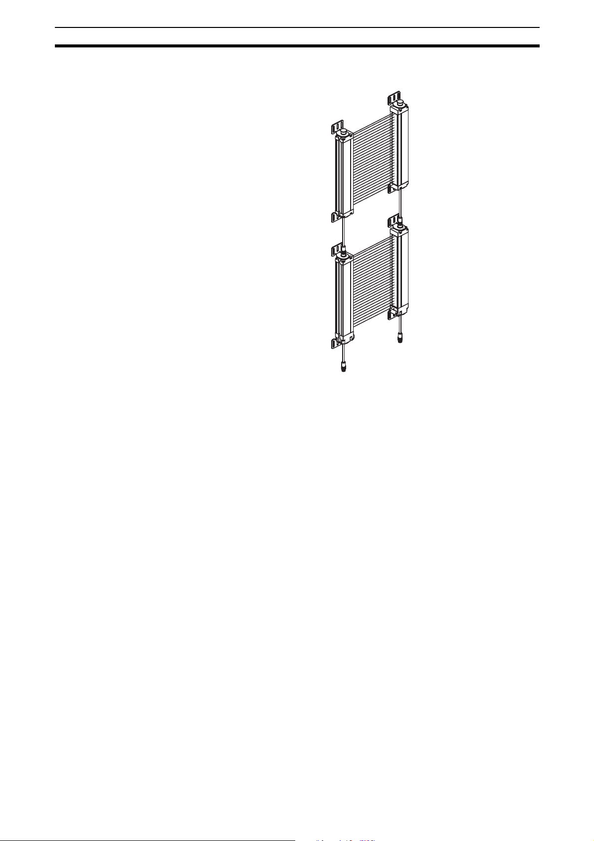
Chart Chart
1 Receiver 7 Transmitter
2 Individual beam Indicators (one with every beam) -
Red LED
3 Blanking Active - Amber LED 9 Flip door, Access to configuration switches (on
4 INTERLOCK or ALARM indicator - Yellow LED 10
5 MACHINE RUN/STOP indicator - Green/Red LED 11 Status Indicator - Yellow LED
6 RECEIVER connections M12 (Male) 12 Slide Mounting T-Slot
1 +24 V DC - Brown 13 Transmitter connections M12 (Male)
2 0 V DC - Blue 1 0 V DC - Blue
3 Earth - Green 2 +24 V DC - Brown
4 OSSD 2 - White 3 MTS - White
5 Start or EDM (Mode Select) - Yellow 4 MTS return - Black
6 EDM - Red 5 Earth - Green
7 Auxiliary Out - Pink
8 OSSD 1 - Black
8 Detection Zone
transmitter and receiver)
RECEIVER LED
INDICATORS
4
3
3
8
DETECTION
ZONE
TRANSMITTER
1
RECEIVER
12
5
ALTERNATE
T-SLOT
MOUNTING
9
13
TRANSMITTER
1
2
7
8
6
4
5
6
LED INDICATOR
11
7
2
10
1
2
5
3
4
MS4800 - SELECTOR SWITCH ACCESS
ENDCAP
WITH
DOOR
321 546
321546
RECEIVER SWITCHES TRANSMITTER SWITCHES
ON
ON
SELECTOR SWITCH
ACCESS
RECEIVER
12
TRANSMITTER
ON
4
Page 23

The MS4800 system is a microprocessor-controlled, infrared, transmittedbeam safety light curtain. The system consists of a receiver assembly and a
transmitter assembly. The receiver and transmitter assemblies are not physically interconnected.
It complies with a Type 4 according to EN/IEC 61496 and category 4 according to EN954-1.
An MS4800 system is used where personnel protection is required. Typical
applications include packaging machines, back side protection of presses and
textile machinery.
4-1 Operating States
The operating condition of an MS4800 system is described in terms of states.
The following operating states exist for an MS 4800 system.
4-1-1 Machine Run
The two receiver safety outputs are in the ON state, the green MACHINE RUN
indicator is lit, and the auxiliary output is in a state consistent with its configuration. The protected machine is allowed to operate. Pressing and releasing
the start button has no effect.
SECTION 4
System Operation
4-1-2 Machine Stop
4-1-3 Interlock
4-1-4 Alarm
The two receiver safety outputs are in the OFF state the red MACHINE STOP
indicator is lit, and the auxiliary output is in a state consistent with its configuration. The protected machine is not allowed to operate.
The two receiver safety outputs are in the OFF state, the red MACHINE STOP
indicator and yellow INTERLOCK indicator are lit. The auxiliary output is in a
state consistent with its configuration. The INTERLOCK state does not allow
the protected machine to operate until the detection zone is clear of obstructions and the start button is pressed and released.
The two receiver safety outputs are in the OFF state, the red MACHINE STOP
indicator is lit, the yellow INTERLOCK indicator is flashing and the auxiliary
output is in the OFF state. The alarm state does not allow the protected
machine to operate. The primary difference between ALARM and INTERLOCK is that the MS4800 system will remain in the alarm state until the alarm
is corrected, and then applying a power cycling or an external start button
press and release.
5
Page 24

Operating Modes Section 4-2
4-2 Operating Modes
System operating modes determine the start-up and operating behavior of an
MS4800 system. Operating modes definitions rely on the operating states
presented above. Operating mode selection may be performed via the configuration switches on the MS4800 transmitter and receiver.
Note If internal alarms are detected by the system during power-up or operation, it
will enter the Alarm state with its safety outputs in the OFF state.
4-2-1 Automatic start
The MS4800 will power-up with its safety and auxiliary outputs OFF, and if the
detection zone is not obstructed, enters the MACHINE RUN state. In this
state, when an object is sensed entering the detection zone, the MS4800 system will change from MACHINE RUN to MACHINE STOP and remain in this
state until the obstruction is removed. Once the detection zone is clear, the
MS4800 system will automatically
RUN.
4-2-2 Start/Restart Interlock
The MS4800 will power-up with its safety outputs off end enter the INTERLOCK state if the detection zone is clear (or the fixed blanking pattern is satisfied) and no alarms are detected. To initially enter the MACHINE RUN state
the operator must press and release the Start button. Once in the MACHINE
RUN state, when an object is sensed entering the detection zone, the system
will change to the MACHINE STOP state. When the detection zone is cleared,
the system will not automatically change to MACHINE RUN but enter the
INTERLOCK state instead. The operator must always press and release the
Start button to enter MACHINE RUN. If the detection zone is not clear the
Start button will have no effect.
change from MACHINE STOP to MACHINE
Note The definitions above mention a start button. See SECTION 11 Connection to
the Machine Control Circuit for wiring of the start button.
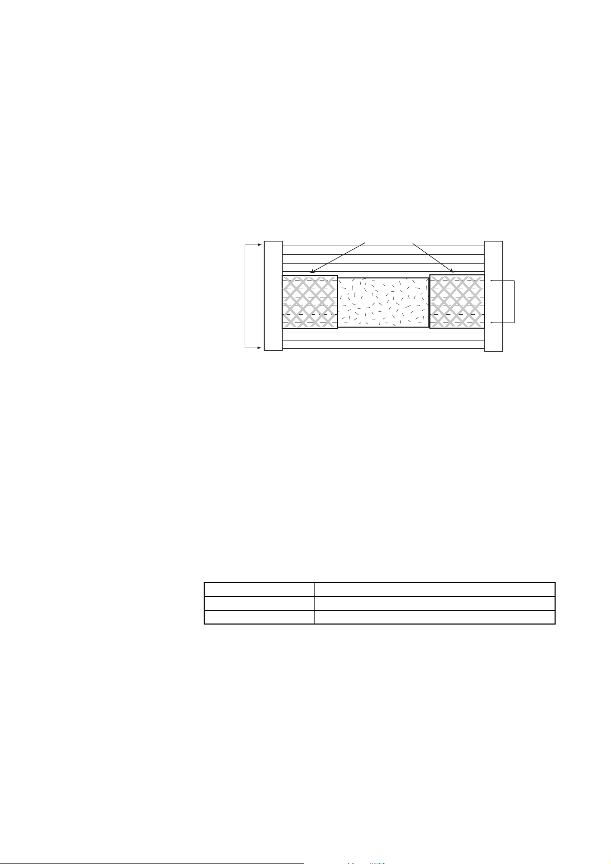
4-3 MS4800FS Cascaded Series
The MS4800 series safety light curtain is available in a "cascaded" version,
referred to as the MS4800FS series. The MS4800FS series allows multiple
transmitters/receivers to be "daisy-chained" in series. This type of arrangement permits the MS4800FS to guard multiple areas of a machine.
4-3-1 MS4800FS Requirements
The MS4800FS is offered in protective heights ranging from 280 mm to
1800 mm for 14 mm resolution and 280 mm to 2120 mm for 30 mm resolution.
• An MS4800FS system has a maximum size limitation based on the number of beams. A master (first) segment cannot exceed 180 beams and the
total of the combined segments cannot exceed 256 beams.
• A cascaded slave segment cannot exceed 128 beams.
• An MS4800FS system may have up to four daisy-chained segments. As
long as the total number of beams does not exceed 256.
• The interconnect cable length limitation between any two segments is in
total max.10 meter for transmitter and receiver.
6
Page 25
MS4800FS Cascaded Series Section 4-3
• It is possible to mix segments with different resolutions within an
MS4800FS system.
"Cascaded" Segment
(Slave)
"Cascaded" Segment
(Slave)
Transmitter
Segment
Receiver
Segment
(Master)
(Master)
4-3-2 MS4800FS Segment Reduction Restart Procedure
!WARNING Do not remove cascaded segments from your installation without making sure
that the accessible areas are protected by other measures. Failure to do so
may result in serious injury.
When you reduce the number of cascaded segments you cause a flex bus
fault. The MS4800FS will enter a fault condition, indicated by error code "95"
on the indicators in the bottom part of the device. This fault code indicates that
there was a reduction in the number of cascaded segments. If the number of
segments is reduced while power is off, the light curtain will power on with
fault code "100".
There is one possibility to clear this fault and restore operation on the reduced
size MS4800FS. The start switch needs to be pressed while the power is
applied. The three indicator LEDs (red, yellow, amber) will flash for approximately three seconds. The start switch must be released while the LEDs are
flashing to clear fault code "100". Since the MS4800FS has a configurable
start input, care must be taken to ensure that the correct contact configuration
is used and that it is wired properly.
The transmitter will not fault if the number of segments is reduced. However,
to operate normally the transmitter must always match the receiver in the
number of segments and beams.
7
Page 26

MS4800FS Cascaded Series Section 4-3
8
Page 27
!WARNING Use of Fixed Blanking and Floating Blanking will make an MS4800 system
less sensitive to objects in the detection zone. Improper use of these features
can result in severe injury to personnel. Fixed Blanking may require a hard
barrier guard. Fixed Blanking and Floating Blanking may require an increase
in the safety distance. Read the following section carefully.
5-1 Fixed Blanking
SECTION 5
Detection Options
Additional Hard Guarding
Fixed Blanking Area
Obstruction
Detection Zone
Light Curtain Light Curtain
Fixed Blanking allows a system to blank optical beams and record the exact
pattern. A system can record and store a single pattern. The protected zone's
object detection is then based on the stored pattern. All obstructed optical
beams recorded during the selection must remain blocked and all clear
beams recorded during the selection must remain clear for the system to
enter or remain in the MACHINE RUN state.
A Fixed Blanking pattern may consist of more than one Fixed Blanked area.
Individual Fixed Blanked areas must be separated by at least one beam that
is always clear. A Fixed Blanking area may not crossover between "flexible"
segment boundaries.
Each Fixed Blanked area has a size and positional tolerance of ±1 beam to
allow for slight position variance and only the two beams on the edges of the
blanked area are allowed to vary. Because of this position tolerance, a reduction of the optical resolution takes place on the border area of Fixed Blanking
patterns. This reduction comprises two beams.
Tolerance effect of Fixed Blanked area on Resolution
Standard Resolution Effective Resolution at Ends of Fixed Blanked Areas
14 mm 34 mm
30 mm 60 mm
Note The tolerance does not reduce the resolution of the entire light curtain, only
the ends of Fixed Blanked Areas. The user must consider the increased resolution of the two beams at the ends of each Fixed Blanked Area.
9
Page 28
Fixed Blanking Section 5-1
The effect of this tolerance also allows the number of blocked beams to vary
±1. For example, a Fixed Blanked area of 8 blanked beams is allowed to
increase to 9 beams or decrease to 7 beams and the light curtain will remain
in MACHINE RUN.
No Fixed
Blanking
MACHINE
STOP
Clear Optical
Channel
Fixed
Blanking
Enabled
MACHINE
RUN
Fixed
Blanking
Enabled
MACHINE
RUN
Blocked Optical Channel
Fixed
Blanking
Enabled
MACHINE
RUN
Fixed
Blanking
Enabled
MACHINE
STOP
Optical Channel
Selected by Fixed
Blanking
Fixed
Blanking
Enabled
MACHINE
STOP
There is an exception when there is only one clear beam separating Fixed
Blanked areas. For only this case, there is no positional tolerance allowed on
that side of the clear beam for the object closest to the entry endcap so that
clear beam can only be used by the object further away from the entry endcap. See the following table:
Opposite to entry endcap end
Fixed blanking enabled Fixed blanking enabled Fixed blanking enabled
10
MACHINE RUN MACHINE RUN MACHINE STOP
Entry endcap end
The minimum number of beams in a Fixed Blanking area is one. If only one
beam is blanked, the number of blocked beams has a size tolerance of +1/-0
meaning the number of blocked beams can increase to two but the area cannot be completely eliminated.
The Fixed Blanking pattern must not prevent the light curtain from synchronizing. This means that the size of the blanked object can not exceed certain limits as long as synchronization is maintained.
Fixed Blanking is allowed during all modes of operation (automatic start, start
and start/restart interlock).
Page 29
Fixed Blanking Section 5-1
IBIs of blocked
beams flash.
Red and amber LEDs and IBIs
flash to indicate the
Program switch is active.
321 546
321546
ON
ON
321 546
321546
ON
ON
off
off
on
on
SWA
SWB
IBIs of blocked
beams flash.
Yellow LED turns on to indicate
the pattern has been programmed
and the Start button is active.
321 546
321546
ON
ON
ononFlip
SWA
SWB
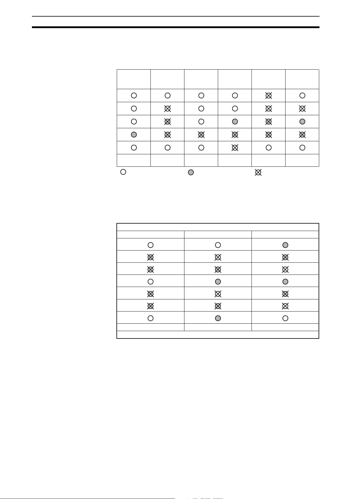
5-1-1 Selecting Fixed Blanking with selector switches
To use Fixed Blanking, the operator enables the option using the selector
switches. A new Fixed Blanking pattern is recorded when the MS4800
receiver is in MACHINE STOP, the blanking function is active and the Program
function is activated. If the Fixed Blanking feature is disabled, the stored protected zone patterns are cleared.
1. The obstruction is placed
ON
ON
IBIs of blocked
beams are On.
within the detection zone
and the receiver goes to
MACHINE STOP state.
An authorized user then
sets the selector switches
321 546
321546
in the receiver endcap to
select Fixed Blanking Enable. The MS4800 enters
Amber LED turns on to indicate
in Fixed Blanking mode.
a fault state and power is
cycled or the Start switch is activated to clear the fault. When the receiver
powers up it will be in Fixed Blanking mode with the red and amber LEDs
lit.
2. The authorized user then
enables the Program
switch by setting both
Fixed Blanking switches to
the off position and then
both to the on position.
When the first Fixed
Blanking switch is flipped,
the red LED begins flashing at a rate of 3Hz. When
the final Fixed Blanking
switch is flipped, both the red and amber LEDs and the IBIs (Individual
Beam Indicators) of the blocked beams start flashing to indicate the Program switch is enabled. The authorized user has 10 minutes to complete
the programming of a pattern.
3. To program a pattern, the
authorized user must flip
(off/on or on/off) the Program switch once. Once
pattern is programmed the
yellow LED (INTERLOCK)
turns on. During 10
minute period, the user
may program as many
times as needed, allowing
for adjustment in the
placement of the obstruction.
11
Page 30
Fixed Blanking Section 5-1
4. The user must then press
and release the Start button or perform a power cycle. The MS4800 receiver
then resets. If no faults are
detected and the state of
the optical beams matches the recorded Fixed
Blanking pattern, the re-
on
321 546
321546
on
Amber LED is on to indicate
ceiver will enter the INTERLOCK or MACHINE RUN condition depending upon the selected Start
Mode. The amber receiver Blanking Active LED will be on.
5. If the 10 minutes period
expires, the amber LED
and IBIs (Individual Beam
Indicators) quit flashing
and the yellow LED (INTERLOCK) goes on. The
user can start another
programming sequence
by setting both Fixed
Blanking switches off and
on
321 546
321546
on
Amber LED is off to indicate
in Fixed Blanking is disabled.
then on. The user may
start normal operation by a press and release of the start button or by performing a power cycle.
6. To exit Fixed Blanking the
user sets both selector
switches to the off position, then either presses
and releases the Start button or performs a power
cycle. The receiver will
power up with the amber
LED off.
The amber LED and IBIs quit flashing
to indicate program switch is disabled.
The yellow LED turns on to indicate the
Start button is active.
off
321 546
321546
off
IBIs of blocked
beams off.
ON
SWA
ON
SWB
in Fixed Blanking mode.
IBIs of blocked
beams on.
ON
SWA
ON
SWB
IBIs of blocked
beams on.
ON
SWA
ON
SWB
Note Please refer for further information to the FAQ to section 17-6.
12
Page 31

Floating Blanking Section 5-2
5-2 Floating Blanking
!WARNING Use of Fixed Blanking and Floating Blanking will make the MS4800 system
less sensitive to objects in the detection zone. Improper use of these features
can result in severe injury to personnel. Fixed Blanking may require a hard
barrier. Fixed Blanking and Floating Blanking may require an increase in the
safety distance. Read the following section carefully.
One channel can be obstructed at any location in the detection zone as long
as the optical synchronization is maintained. Please refer to chapter 5-4 Opti-
cal Synchronization for further details.
This means that an object can freely float from one end of the protective field
to the other without the MS4800 system entering the MACHINE STOP state.
The obstructed channels are not fixed at a single location but "float" through
the detection zone.
1
Channel
Floating
Blanking Active
Channel 1
Floating
Blanking
Inactive
1
Channel
Floating
Blanking Active
1
Channel
Floating
Blanking Active
1
Channel
Floating
Blanking Active
Channel 2
Channel 3
Channel 4
Channel 5
System
Response
MACHINE STOP
Clear Optical Channel
1
Exception
0
Exceptions
Machine
Run
1
Exception
Machine
Run
Optical Channel is obstructed
MACHINE STOP
Note Please refer for further information to the FAQ to section 17-6.
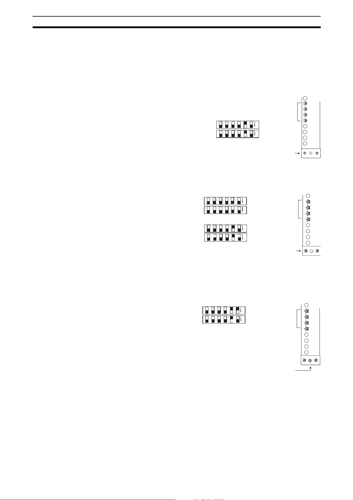
5-2-1 Selecting Floating Blanking with selector switches
Using the selector switches an authorized user can activate the Floating
Blanking function. This allows the system to operate with one obstructed optical beam anywhere within the protected zone. This obstruction is permitted
anywhere within the protected zone and is permitted to move over time. After
setting the appropriate selector switches, the receiver enters the Power-On
Self Test state and if no faults are detected the receiver shall enter the INTERLOCK or MACHINE RUN condition depending upon the selected operating
mode.
2
Exceptions
2
Exceptions
MACHINE STOP
!WARNING Two-Beam Floating Blanking is not available on the MS4800 system.
Floating Blanking Effects on Minimum Object Resolution
Standard Minimum Object Resolution
(No Floating Blanking)
14 mm 24 mm
30 mm 50 mm
Minimum Object Resolution with
1 Beam Blanking
13
Page 32

Fixed Blanking with Floating Blanking Section 5-3
5-3 Fixed Blanking with Floating Blanking
!WARNING Use of Fixed Blanking and Floating Blanking will make MS4800 system less
sensitive to objects in the detection zone. Improper use of these features can
result in severe injury to personnel. Fixed Blanking may require a hard barrier
guard. Fixed Blanking and Floating Blanking may require an increase in the
safety distance. Read the following section carefully.
Possible combinations:
Function Fixed Blanking Floating Blanking
Fixed Blanking N/A Yes
Floating Blanking Yes N/A
When both Fixed Blanking and Floating Blanking are selected, the floating
channels are allowed to occur anywhere within the detection zone except the
area selected by Fixed Blanking.
5-3-1 The effect of Fixed or Floating Blanking on minimum object
resolution
When fixed Blanking and/or Floating are active, the safe mounting distance is
affected. Fixed and Floating Blanking desensitize the light curtain and
increase the size of the minimum detectable object. The increase is equal to
the beam spacing distance for each beam that is disabled.
If the size of the object detected by the system increases the minimum safe
distance must also be increased. Use the minimum object sensitivity given in
the following tables to determine the new figure to use when computing the
safety distance.
MS4800 system - 14 mm resolution
Total number of Beams Disabled by
Fixed and/or Floating Blanking
None 14 mm
1 Beam 24 mm
2 Beams 34 mm
3 Beams 44 mm
4 Beams 54 mm
5 Beams 64 mm
> 64 mm
Effective Resolution
14
MS4800 system - 30mm resolution
Total number of Beams Disabled by
Fixed and/or Floating Blanking
None 30 mm
1 Beam 50 mm
> 64mm
Effective Resolution
Page 33

Optical Synchronization Section 5-4
5-4 Optical Synchronization
The synchronization between the MS4800 system transmitter and receiver is
optical, so the system does not use one specific beam. To establish synchronization the system needs to have a certain number of consecutive clear
beams (see following table) within the first master segment. If they are not satisfied, the system will enter a MACHINE STOP state and every other Individual Beam Indicator will light. When the beams are cleared, the system will resynchronize itself and enter a state consistent with its operating mode. Once
the synchronization is established, it can be maintained as long as the
required number of consecutive clear beams can be satisfied anywhere in the
system (including flex segments).
Light Curtain Beam Count Synchronization Beam Requirement
12 - 16 beams 6 consecutive clear beams
17 - 32 beams 7 consecutive clear beams
33 - 64 beams 8 consecutive clear beams
65 - 128 beams 9 consecutive clear beams
129 - 256 beams 10 consecutive clear beams
Because of these restrictions, when programming a fixed blanking object(s),
the size of the fixed or monitored blanking object(s) (8 beams +/- 1 beam
tolerance) must comply with the number of consecutive clear beams stated in
the previous table within the first master segment.
In addition to that, any fixed or monitored blanking programming must be done
with at least one (1) clear beam on each flex segment.
Example:
A MS48000S-EA-014-1320 has 132 beams. In blanking application,
10 consecutive beams have to be free for optical synchronization. The
remaining 122 beams can be used for fixed blanking applications (max
8±1 beams).
15
Page 34

Optical Synchronization Section 5-4
16
Page 35

Diagnostic and Test Features
6-1 Individual Beam Indicators (IBI)
All MS4800 systems have a visible red LED as an Individual Beam Indicator
adjacent to each infrared beam. These IBIs are located on the receiver. The
IBI will light when the infrared beam fails to meet the conditions necessary for
the system to remain in the MACHINE RUN state. When less than 10 consecutive beams are clear, every other IBI will light indicating that the MS4800 is
not synchronized. IBIs are not a safety critical component. An IBI failure will
not cause an alarm condition and the system will continue to operate.
Additionally, error codes are displayed using the IBIs close to the connector
endcap.
6-2 External Device Monitoring (EDM)
EDM is an important safety function. It monitors the MS4800 system interface
to the guarded machine, checks to ensure that the control elements are
responding correctly to the light curtain and detects any inconsistency
between the two external control devices. This is necessary to detect a malfunction within the interface which prevents a stop signal from reaching the
machine controller. The connection for the EDM is made at the receiver. On
power-up, the MS4800 system looks for a closed to 0VDC condition. If this is
found, it will enter a state consistent with the selected operating mode. When
the MS4800 system enables its safety outputs, it monitors the external
devices for a closed to open transition. This transition must occur within
300ms or the MS4800 system will then enter an alarm state. Additionally, if
the EDM connections are incorrectly wired, the system will enter an alarm
state.
SECTION 6
Note For proper operation of the MS4800 system when EDM is not active, the EDM
input must be wired to the MS4800 system 0 VDC line.
The EDM function can be activated and deactivated using the selector
switches on the receiver unit.
6-3 Machine test signal (MTS)
Some applications require that the machine guarding system be tested by the
machine controller during a non-hazardous portion of the machine cycle to
verify that the guarding system is functioning properly. The MTS option on the
transmitter provides this capability. The MTS is provided by placing a normally-closed switch across the MTS and MTS Return lines of the transmitter.
When the transmitter recognizes a close-to-open transition on this switch a
beam block state will be simulated on the transmitter and the receiver will
enter the MACHINE STOP state. MTS is active as long as the switch is held
open.
6-4 Range selection
The MS4800 offers operating range selection: short range is 3 m and long
range is 7 m for the 14 mm models. For the 30mm models the short range is
8m and long range is 20 m. This function is useful when there are many light
curtains operating within a small space and the possibility of cross-talk is
likely.
17
Page 36

Start/Restart Input Section 6-5
6-5 Start/Restart Input
The characteristic of the Start/Restart Input is shown in the following schematic:
MS4800
Start
N.O.
+24 VDC
+24 VDC
0 VDC
Reset
18
Page 37

Using selector switches to set features
ENDCAP WITH DOOR SELECTOR SWITCH ACCESS
RCVR XMTR
RECEIVER SELECTOR SWITCHES
TRANSMITTER SELECTOR SWITCHES
SELECTOR SWITCH ACCESS
321 546
12
321546
ON
ON
ON
Scan Code
Frequency A 1 = Off
Frequency B 1 = On
MTS
Disabled 2 = Off
Enabled 2 = On
ON
MTS
Scan Code
TRANSMITTER SELECTOR SWITCHES
(Shown in factory default positions)
1
2
!WARNING Make sure that foreign objects such as water, oil, or dust do not enter the
inside of the MS4800 system while the cover for the selector switches is open.
7-1 Access to the selector switches
The switches are located behind a flip door on both the transmitter and
receiver. The flip up doors are opened by loosening two retaining screws (see
illustration below).
SECTION 7
7-1-1 Transmitter selector switch settings
Switch Position Function Factory default
1 SCAN CODE SCAN CODE A
2MTSMTS OFF
19
Page 38

Operating mode selection Section 7-2
7-1-2 Receiver selector switch settings
Switch A Position Function Switch B Position Function Factory Default
1 Auto Start or Start/
Restart Interlock
2 EDM 2 EDM Disabled (OFF)
3 Scan Code 3 Scan Code Scan Code A (OFF)
4 Floating Blanking 1 4 Floating Blanking 1 Disabled (OFF)
5 Fixed Blanking 5 Fixed Blanking Disabled (OFF)
6 Program (Non-safety) 6 Range (Non-safety) Program (toggle)
1 Auto Start or Start/
Restart Interlock
Auto Start (OFF)
Short Range (OFF)
Operating Mode
Automatic Start 1 = Off 1 = Off
Start/Restart Int 1 = On 1 = On
EDM Disabled 2 = Off 2 = Off
EDM Enabled 2 = On 2 = On
Scan Code A 3 = Off 3 = Off
EDM
Auto/SRI
SW A
SW B
RECEIVER SELECTOR SWITCHES
(Shown in factory default positions)
321 546
321546
EDM
Auto/SRI
Scan Code
FB1
FB1
Program
ON
ON
Range
Fixed BK
Fixed BK
Scan Code
Scan Code B 3 = On 3 = On
FB1 Disabled 4 = Off 4 = Off
FB1 Enabled 4 = On 4 = On
Fixed Blanking
Disabled 5 = Off 5 = Off
Enabled 5 = On 5 = On
Program 6 = Toggle
Operating Range
Short Range 6 = Off
Long Range 6 = On
7-2 Operating mode selection
The operating mode is selected by setting position 1 of switches A and B,
located on the receiver. Any mismatch between the settings of switches A and
B will result in an alarm condition. The available operating modes are automatic start and Start/Restart Interlock.
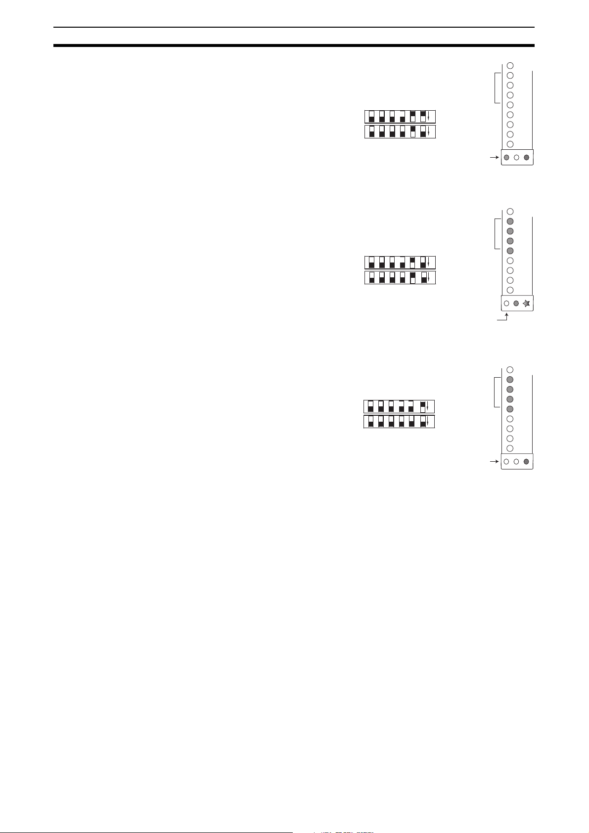
7-3 Selecting and programming Fixed Blanking
SW A SW B
Refer to section 5-1 Fixed Blanking for details on selecting and programming
Fixed Blanking function.
7-4 Selecting and programming Floating Blanking
Floating Blanking is activated by setting position 4 of Switches A and B
located on the receiver.
Note When Floating Blanking is active, the amber LED will illuminate to indicate
that the system is operating in a less sensitive state.
7-5 Selecting External Device Monitoring (EDM)
EDM is activated by setting position 2 of Switches A and B located on the
receiver. Any mismatch between the settings of Switches A and B will result in
an alarm condition.
7-6 Selecting Machine Test Signal (MTS)
MTS is activated by setting position 2 located on the transmitter end cap.
20
Page 39

Selecting Scan Codes Section 7-7
Scan Code A
Scan Code B
7-7 Selecting Scan Codes
The MS4800 receiver and transmitter offer scan code selection to minimize
cross talk. On the transmitter this is activated by setting position 1. On the
receiver this is activated by setting position 3 of switch A and switch B.
Note Both receiver and transmitter must be set to the same code.
Example:
To mitigate interference from other light curtains, the MS4800 system has two
possible scan codes, A and B. The transmitter and receiver units must be set
to the same scan code for the receiver to enter the MACHINE RUN state.
21
Page 40

Selecting Scan Codes Section 7-7
22
Page 41

8-1 Safety Outputs (OSSDs)
!WARNING This product is designed for use on a 24 VDC, negative ground (protective
earth) electrical system only. Never connect the MS4800 system to a positive
ground (protective earth) system. With a positive ground (protective earth)
wiring scheme, certain simultaneous shorts of both safety outputs may not be
detected and the guarded machine may not stop, resulting in severe operator
injury.
The MS4800 system receiver supplies two independent PNP type safety outputs to provide run/stop signals to the guarded machine. In the MACHINE
RUN state, the safety outputs are electrically conducting and source 625 mA
of current at 24 VDC. In the MACHINE STOP state, the outputs are not electrically conducting.
8-2 Auxiliary Output
!WARNING Do not use the auxiliary output or external indicator output for safety applica-
tions. Human body may not be detected when MS4800 system fails, resulting
in serious injury.
SECTION 8
Outputs
This is not a safety output. The MS4800 system supplies one auxiliary output.
The configuration of this output is "PNP follow". So the signal on the auxiliary
output is similar to the status of the OSSD outputs. It will source up to 100 mA
at 24 VDC.
23
Page 42

Auxiliary Output Section 8-2
24
Page 43

Safe Mounting Distances
!WARNING Never install an MS4800 system without
regard to the safety distance. If the MS4800
system is mounted too close to the point of
operation hazard, the machine may not stop in
time to prevent an operator injury.
An MS4800 system must be mounted far enough from the machine danger
zone so the machine will stop before a hand or other body part reaches the
hazardous area. This distance is called the safety distance. It is a calculated
number based on a formula.
The safety distance "S" is the minimum safe distance between the safety light
curtain and the point of operation (pinch point).
Calculation of the safety distance "S" is based on the European standard
EN999 and applies to safety light curtains that are used in industrial environments.
SECTION 9
Light Curtain
S
9-1 Safety distance for safeguarding danger points
Additional countermeasures
S
Direction of
approach
!WARNING Additional countermeasures may be necessary to prevent access to the dan-
gerous area from above, below, the sides or the rear of the machine.
25
Page 44

Safety distance for safeguarding danger points Section 9-1
9-1-1 Calculation example for systems with a resolution of <40 mm
Formula according to EN999: S = (K x T) + C
Where S = minimum distance in millimeters from the danger zone to the
detection point, line, plane or zone. If the result of the calculation is less than 100 mm, a distance of at least 100 mm must
still be maintained.
K = Approach speed in mm/s. In the close area of 500 mm, the
speed is calculated at 2000 mm/s. If the distance is greater
than 500 mm, K can be calculated as 1600 mm/s. In this
case, however, a minimum of 500 mm applies for the safety
distance.
T = the overall system stopping performance in seconds
T = t
+ t2 + t
1
t1 = response time of the safety light curtain in seconds,
t
= response time of the safety interface tsi, if any.
2
t
= maximum stopping time of the machine tm in
3
Please refer to the technical information of the safety
Interface and the machine for the response time and stopping
time details.
C = 8 x (d-14 mm), but not less than zero.
d = minimum object resolution of the MS4800 system in
S = (2000 mm/s x T) + 8 x (d-14 mm)
This formula applies for all minimum distances of S up to and
including 500 mm. The minimum value of S shall not be less
than 100 mm.
If S is found to be greater than 500 mm using the formula
above, then the formula below can be used. In this case the
minimum value of S shall not be less than 500 mm.
S = (1600 mm/s x T) + 8 x (d-14 mm)
3
given in the table in chapter 16.
seconds.
millimeters, therefore:
26
Page 45

Safety distance for safeguarding danger areas Section 9-2
H
S
Direction of
approach
50 mm - maximum distance
to avoid walking behind
9-2 Safety distance for safeguarding danger areas
!WARNING Additional countermeasures may be necessary to prevent access to the dan-
gerous area from above, below, the sides or the rear of the machine.
The height of the protective field "H" above the reference plane and the resolution "d" of the MS4800 system have the following relationship:
= 15 x (d -50) or d = (H
H
min
H
= Height of the protective field above the reference plane,
min
maximum height = 1000 mm.
It is considered that if height is equal or less than 300 mm,
adults can not crawl under.
d = resolution of the MS4800 system
S = (K x T) + C
For K and T please refer to the previous chapter
C = (1200 mm - 0,4 x H) but not less than 850 mm
(arm length)
H = Height of protective field above the floor
S = (1600 mm x T) + (1200 - 0,4 x H)
/ 15) + 50
min
27
Page 46

Safety distance and beam heights in access guarding Section 9-3
H
S
L
Direction of
approach
9-3 Safety distance and beam heights in access guarding
!WARNING Additional countermeasures may be necessary to prevent access to the dan-
gerous area from above, below, the sides or the rear of the machine.
According to EN999 and EN294:
Resolution Lowest beam above
reference plane
14 mm In accordance with
EN 294
30 mm In accordance with
EN 294
The height of the protective field "H" above the reference plane and the resolution "d" of the MS4800 system have the following relationship:
S = (K x T) + C
For K and T please refer to the previous chapter
C = 8 x (d - 14)
d = resolution of the MS4800 system
S = (2000 mm x T) + 8 x (d - 14)
Highest beam above
reference plane
In accordance with
EN 294
In accordance with
EN 294
Additional
amount C
(see formula)
0mm
128 mm
28
Page 47

!WARNING Install the sensor system so that it is not affected by reflective surfaces. Fail-
ure to do so may hinder detection, resulting in serious injury.
10-1 Reflective Surface Interference
A reflective surface adjacent to the detection zone can deflect the optical
beam and may cause an obstruction in the zone not to be detected. The
reflective surface may be part of the machine, mechanical guard or workpiece. Therefore, a minimum distance (d) must exist between the reflective
object and the center line of the detection zone. The Test procedure (Appendix B) must be used to test for this condition.
In this picture, the interruption is clearly detected. The reflective object is outside of the beam angle.
SECTION 10
Installation
Operating range R
Approach direction
Interruption
EAA
Tr ansmitter Receiver
d = distance to
reflective surface
Reflective surface
Operating range R: is the effective working distance of the MS4800 system,
from the transmitter to the receiver.
EAA: is the effective aperture angle of the Safety Sensor.
it is ±2,5° for MS4800 system
distance d: is the minimum distance to a reflective surface.
This distance must be bigger than:
d
MS4800 system = tan(2,5°)×R
min
Be aware that reflective surface interference may also appear above and
below the sensing field.
29
Page 48

Cross Talk Mitigation Section 10-2
0
0,2
0,4
0,6
0,8
1
1,2
1,4
1,6
1,8
2
0,1 0, 2 0,5 1 2 3 4 5 6 7 8 9 10 11 12 13 14 15 16 17 18 19 20
Range [m]
Minimum Distance d [m]
Scan Code A
Scan Code B
This example shows the minimum distance from the reflective surface, d, to
one side of the beam center line
10-2 Cross Talk Mitigation
To mitigate interference from other light curtains, the MS4800 system has two
possible scan codes, A and B. The transmitter and receiver units must be set
to the same scan code for the receiver to enter the MACHINE RUN state.
30
Page 49

General Mounting Considerations Section 10-3
MS4800 point of
operation guarding
MS4800FS 3-sided guarding MS4800FS 2-Axis guarding
10-3 General Mounting Considerations
10-3-1 Additional Guarding
Areas of access to the point of hazardous operation not guarded by the
MS4800 system must be protected by suitable means such as a fixed barrier
guard, an interlocked guard or a safety mat system.
Supplemental
D
s
LIGHT CURTAIN
Hazard
Mechanical
Barrier
Zone
Supplemental
Guarding
Example
Supplemental
Guarding
Supplemental
Guarding
Supplemental
Guarding
Guarding
10-3-2 Added Mounting Rigidity
ALTERNATE
T-SLOT
MOUNTING
ALTERNATE
T-SLOT
MOUNTING
It is recommended that when installing a
MS4800 larger than 1000 mm in length,
you use an additional mounting bracket.
This is to be installed using the T-slot on
the backside of the transmitter and
receiver.
Note
For light curtain > 1000 mm its recommended to buy extra T - slot mounting
bracket as Accessory.
31
Page 50

General Mounting Considerations Section 10-3
Transmitter
Receiver
Transmitter
Receiver
Machine 1 Machine 2
PREFERRED INSTALLATION
Code A
Code A
Machine 1
Transmitter
Transmitter
Receiver
Machine 2
Receiver
NOT RECOMMENDED INSTALLATION
Code A
Code A
10-3-3 Installation of Multiple Systems
When two or more MS4800 systems with the same scan code are mounted in
close proximity and in alignment with each other, precautions should be taken
to avoid one system interfering with another. This can be corrected by mounting the transmitters and receivers back-to-back or stacked.
The scan code feature of the MS4800 system allows for placement of systems
in close proximity and in line with each other. The distinctive coding of the
beams provide for unique operation of a system while in view of another system with a different scan code. Two unique codes are available on the
MS4800.
10-3-4 Detection Zone
10-3-5 Alignment
10-3-6 Input Power Requirements
Transmitter
Machine 1
Code A
Receiver
Transmitter
Machine 2
Code B
Receiver
The system detection zone is delineated by the inside edge of the transmitter
and receiver endcaps. The area outside these marks is not protected. Position
the system so that it is only possible to access the danger point through the
detection zone.
Physical alignment of the transmitter and receiver is easiest when the system
is in the automatic start operating mode with Fixed Blanking inactive. The
units should be in the same plane and at equal height.
The Individual Beam Indicators will light when a part of the Safety Light Curtain is out of alignment.
The system operates directly from 24 VDC ±20%. Power to the system must
come from a power supply which meets the requirements of EN/IEC60204-1
and EN/IEC 61496-1.
The power supply must guarantee safe insulation from the mains voltage in
accordance with IEC60742 and be able to cover a drop of supply voltage of at
least 20 ms. Omron offers suitable power supplies. The power supply must
not supply any other parts of the machine with power other than the safety
components connected. Transmitters and receivers must be supplied from a
shared power supply and must be fused against overcurrent.
32
Page 51

General Mounting Considerations Section 10-3
10-3-7 Requirements for Perimeter Guarding
In perimeter guarding applications the MS4800 system detection zone is
placed around the outside perimeter of a guarded machine. This placement
leaves space for personnel to stand between the detection zone and the hazardous machine.
In this case, the guarded machine must only be restarted using a switch
located outside and with a full view of the area of hazardous motion. Operation of the MS4800 system In the Start/Restart Interlock operating mode is
suitable for perimeter guarding.
10-3-8 Marking Minimum Object Resolution
Serial number labels on the transmitter and receiver indicate possible minimum object resolutions. During installation, use a permanent marker to
obscure the object resolution not set and add information about the effective
resolution. This will depend on whether no floating blanking or 1-beam floating
blanking is set.
33
Page 52

General Mounting Considerations Section 10-3
34
Page 53

SECTION 11
Connection to the Machine Control Circuit
!WARNING This product is designed for use on a 24 VDC, negative ground (protective
earth) electrical system only. Never connect the MS4800 system to a positive
ground (protective earth) system. With a positive ground (protective earth)
wiring scheme, certain simultaneous shorts of both safety outputs may not be
detected and the guarded machine may not stop, resulting in severe operator
injury.
!WARNING Never use only a single safety output to control the machine. Should this sin-
gle output fail, the machine may not stop, resulting in severe operator injury.
The machine must be connected using both safety outputs.
The table below references Pin Numbers, Wire colors and signal names being
used with the MS4800 system.
Receiver cable
Pin No. 1 Input power Brown +24VDC
Pin No. 2 Input power Blue GND
Pin No. 3 Input power Green Functional Earth
Pin No. 4 Output signal White OSSD2
Pin No. 5 Input signal Yellow Start
Pin No. 6 Input signal Red EDM
Pin No. 7 Output signal Pink Aux
Pin No. 8 Output signal Black OSSD1
Transmitter cable
Pin No. 1 Input power Blue GND
Pin No. 2 Input power Brown +24VDC
Pin No. 3 Input test White MTS
Pin No. 4 Input test Black MTS Return
Pin No. 5 Input power Green Functional Earth
The primary cables for the MS4800 system are industry standard nonshielded cables with an M12 female connector. The receiver and transmitter
incorporate a 0,3 m pigtail with an M12 male connector.
We recommend to use the F39-JMR and F39-JMT cables to connect the
MS4800 system to the machine control system.
35
Page 54

Interconnect cables for cascaded MS4800FS system Section 11-1
TGR cables
Length Receiver Transmitter
2 m F39-TGR-CVL-B-2-R F39-TGR-CVL-B-2-E
5 m F39-TGR-CVL-B-5-R F39-TGR-CVL-B-5-E
10 m F39-TGR-CVL-B-10-R F39-TGR-CVL-B-10-E
Receiver cable
Pin No. 1 Test Input white
Pin No. 2 Input Power + 24 VDC brown
Pin No. 3 Input Power GND Blue
Pin No. 4 OSSD2 pink
Pin No. 5 OSSD1 gray
Pin No. 6 Muting B yellow
Pin No. 7 Muting A Green
Pin No. 8 Muting lamp connection LMS red
Transmitter cable
Pin No. 1 Test Input white
Pin No. 2 Input Power + 24 VDC brown
Pin No. 3 Input Power GND Blue
Pin No. 4 Not used black
Pin No. 5 Not used green
Note Alternative cables:
F39-TGR-CVL-B-_ cables are industry standard shielded cables with a M12
female connector.
11-1 Interconnect cables for cascaded MS4800FS system
The segment-to-segment cable has a 4 contact M12 connector on each end.
The maximum cable length is 10 meters between segments.
The extension cables are available in lengths of 0.3 m, 0.5 m, 1 m, 2 m, 5 m
and 10 m. A MS4800FS system does not require an extension cable; it has a
150 mm integrated cable (pigtail).
MS4800FS systems are designed with internal circuit protection to protect
from damage when they are connected and disconnected (hot-swap) during
normal operation.
Transmitter Master
10 m -> Slave 1 10 m -> Slave 2 10 m -> Slave 3
Receiver Master
10 m -> Slave 1 10 m -> Slave 2 10 m -> Slave 3 30 m -> RM6
36
Page 55

Connection to two forcibly guided relays Section 11-2
11-2 Connection to two forcibly guided relays
G7S and G7SA series relays provide forcibly guided relay outputs for machine
control. Please refer to the next drawing for details:
Power supply
+24VDC
GND
Protective Earth
*1
MTS requires a NC contact.
If MTS is not used, please
connect MTS and MTS Ret.
Directly.
*2
The K1 and K2 coils must be
suppressed. Please refer to
the documentation of the
relays or co ntactors for
further reference.
TGR cable
Power supply
+24VDC
GND
Protective Earth
*1
MTS requires a NC contact. If
MTS is not used, please connect
MTS and MTS Ret. Directly.
*2
The K1 and K2 coils must be
suppressed. Please refer to
the documentation of the
relays or contactors for further
reference.
Fuse
Fuse
PIN
Earth GN D
Green
Earth
5
+24V
DC
MS4800
Transmitter
Brown
White
+24V
GND
DC
2
1
MS4800
Transmitter
*1
MTS
MTS Earth
Ret.
*1
Blue
Black
MTS
MTS
Ret.
4 3
K1
K2
*2
K1
K2
K1
*2
K2
M
+24V
GND
EDM Sta rt Aux.
DC
MS4800
Receiver
K1
K2
Green
White
Brown
Pink
+24V
Earth
3 2
PIN
MS4800
Receiver
GND
EDM
DC
165
*2
Gray
Start Aux.
K1
Blue
OSSD1 OSSD2
7
OSSD1OSSD
Yellow
Red
4
8
2
K1
K2
K2
*2
M
.
11-3 Connection to a safety relay unit
The following example shows a MS4800 system in combination with a G9SB
safety relay unit from Omron. The G9SB safety relay unit provides forcibly
guided relay contacts for the machine control system.
Power supply
+24VDC
GND
Protective Earth
*1
MTS requires a NC contact.
If MTS is not used, please
connect MTS and MTS Ret.
Directly.
Fuse
Earth GN D
Transmitter
+24V
DC
MS4800
*1
MTS
MTS Earth
Ret.
GND
+24V
EDM Sta rt Aux.
DC
MS4800
Receiver
A2
T31 T32
A1
2313
G9SB-200-D
T12 T2 2
OSSD1OSSD
14 24
K1
2
K1
K2
K1
K2
K2
M
37
Page 56

Connection to a safety relay unit Section 11-3
38
Page 57

SECTION 12
Muting
!WARNING The muting and override functions disable the safety functions of the device.
You must ensure safety using other method when these functions are operating.
!WARNING Install muting sensors so that they can distinguish between the object that is
being allowed to pass through the detection zone and a person. If the muting
function is activated by the detection of a person, it may result in serious
injury.
!WARNING Muting lamps (external indicators) that indicate the state of the muting and
override functions must be installed where they are clearly visible to workers
from all the operating positions.
!WARNING Muting related time must be properly configured for its application by a suffi-
ciently trained and qualified person, and the person must have responsibility
for settings, especially when setting the muting time limit to infinite.
!WARNING Use independent 2 input devices for muting inputs.
!WARNING You must install MS4800 system muting sensor, and physical barrier, and con-
figure time settings for muting so that an operator should not enter hazardous
zone.
!WARNING Install the switch that activates the override in a location that provides a clear
view of the entire hazardous area and where it cannot be activated from within
the hazardous area. Make sure that nobody is in the hazardous area before
activating the override function.
12-1 Muting Controller RM-6
Muting with the MS4800 system is available together with the Muting Controller RM-6.
The MS4800 and an RM-6 offer a limited set of muting functions. The following list describes the muting functions that can be achieved with the MS4800:
• 2 Sensor muting
• 50 ms sensor input filtering
• Mute Bypass configurable: Enable/Disable
• Mute timeout configurable: 2 minutes/No timeout
39
Page 58

Muting Controller RM-6 Section 12-1
The MS4800 system requires a specific sequence to activate the muting function after the RM-6 is connected to the receiver. Once the RM-6 is connected
the system will not operate until either the mute module is removed or the following sequence is followed:
• The MS4800 will fault "71", (mute module enable and configuration
required)
1. Turn ON the power supply of the MS4800 system and the RM6, the start
button must be pressed for app. 3 seconds until all status LEDs of the receiver SLC are flashing shortly.
2. Release the start button while the status LEDs are flashing
3. The MS4800 system performs a system reboot. When this sequence is
properly completed, muting function is enabled.
The status LED of the receiver turns to green and the status LED of the RM6
lights permanently.
When this sequence is properly completed, the system will enable muting.
For further information please check the user manual of the MS4800-RM6.
40
Page 59

13-1 Checkout Procedure
Once the MS4800 system has been configured, mounted, aligned and properly connected to the machine control system, the initial Checkout Procedure
detailed in Appendix A must be performed by qualified personnel. A copy of
the checkout results should be kept with the machine records.
13-2 Test Procedure
!WARNING The tests outlined in the Test Procedure in Appendix B must be performed at
installation, according to the employer's regular inspection program and after
any maintenance, tooling change set up, adjustment or modification to the
MS4800 system or the guarded machine. Where a guarded machine is used
by multiple operators or shifts, it is suggested that the test procedure be performed at each shift or operator change. Testing ensures that the light curtain
and the machine control system work properly to stop the machine. Failure to
test properly could result in serious injury to personnel.
SECTION 13
Checkout and test procedure
The test procedure must be performed by qualified personnel. To test the
MS4800 system with fixed blanking and floating blanking disabled, use the
OMRON STI supplied test object. For applications where fixed blanking or
floating blanking is enabled, see Table in chapter 5-3-1 The effect of Fixed or
Floating Blanking on minimum object resolution to determine the proper size
of the test object.
When using a MS4800 system set for Automatic Start Mode operation, in conjunction with an OMRON safety relay module, it is necessary to verify that the
outputs of the safety relay unit can properly change state by causing an intentional beam break at least every change of shift or 24 hours of operation.
13-3 Using the test object
When using the test object, guide it through
the detection zone as shown:
START
STOP
4800 system
4800 system
41
Page 60

Using the test object Section 13-3
42
Page 61

SECTION 14
Cleaning
Accumulation of oil, dirt and grease on the front window of the MS4800 transmitter and receiver can effect the system operation. Clean the window with a
mild detergent or glass cleaner. Use a clean, soft, lint-free cloth. Painted
MS4800 surfaces may be cleaned with a mild de-greasing cleaner or detergent.
43
Page 62

Section
44
Page 63

Specifications and additional information
15-1 System Specification
Protective height 240 mm - 1800 mm (14 mm resolution)
Object Resolution 14 mm and 30 mm
Operating Range 0.3 m - 7 m (14 mm resolution), DIP SW 6 option
Effective Aperture Angle ±2,5° maximum, transmitter and receiver according to
Safety Output (OSSDs) Two PNP safety outputs, each output sourcing
Response Time Maximum: 59 ms
Auxiliary Output
(non safety)
EDM - Monitor Input 50 mA @ 24 VDC
Start/Restart Input 10 mA @ 24 VDC, Normally open input
Light Source Infrared Emitting LEDs,
Transmitter Indicator Lights ACTIVE (Yellow)
Receiver Indicator Lights MACHINE RUN/STOP (Green/Red)
SECTION 15
Performance
280 mm - 2120 mm (30 mm resolution)
0.3 m - 3 m (14 mm resolution), default
0.3 m - 20 m (30 mm resolution), DIP SW 6 option
0.3 m - 8 m (30 mm resolution), default
IEC61496-2 (2006)
625 mA @ 24 VDC.
Short circuit protection
See table below for more details
One PNP output sourcing 100 mA @ 24 VDC. This output follows the OSSDs.
Wavelength 880 nm
Power Dissipation: 180 mW
Class 1 per EN60825-1
INTERLOCK/ALARM (Yellow)
BLANKING (Amber)
Mechanical
Housing Material Polyurethane powder painted aluminum
Front Window Material Acrylic, Red
End Cap Material Polycarbonate
Mounting Bracket Material Cold rolled Steel
Wiring connections M12-connectors;
Weight See table for more details
8-pin receiver and 5-pin transmitter
45
Page 64

System Specification Section 15-1
Electrical
Power Input Transmitter 24 VDC ±20%, maximum current 285 mA
MTS Input 24 VDC ±20%, 20 mA typ.
Power Input Receiver 24 VDC ±20%, maximum current 1835 mA
Receiver 485 mA + AUX 100 mA +
OSSD1 625 mA + OSSD2 625 mA
Leakage current < 1mA
Capacitive Load < 4.7µF for OSSD output
Inductive Load Please contact your Omron representative for further
Test pulse data
information.
OSSD 1
OSSD 2
t
1
t
2
t
3
t1: Test pulse ≤ 600 µs
t2: 4 ms ≤ Test interval ≤ 40 ms
t3: Repetition ≤ 5min
Muting Option 24 VDC ±20%, 30 mA max.
Muting Duration Approx. 2 min. or No time limit
Power Supply Must meet the requirements of EN/IEC 60204-1 and
EN/IEC 61496-1, and must guarantee safe insulation
from the mains voltage in accordance with IEC 60742
and be able to cover a drop of supply voltage of at least
20 ms.
Protection class
III
(IEC 536 or VDE 106)
Environmental
Enclosure Rating IP65
Operating Temperature -10°C … +55°C
Storage Temperature -25°C … +70°C
Relative Humidity 95% maximum, non-condensing
Vibration (IEC 60068-2-6) 10 - 55 Hz, 10g, maximum on all 3 axes
Shock (IEC 60086-2-29) 10g for 16 ms, 1000 shocks on all 3axes
t
46
Cable length
MS4800 Transmitter
Cable length
MS4800 Receiver
Cable length
MS4800FS system
Connections
Unshielded cables:
Max. 50 m, @ 0.32 mm²
We recommend to use the F39-JMT cables or as
alternative the F39-TGR-CVL-B-_E (shielded) to
connect the MS4800 system to the machine control
system.
Unshielded cables, length is depending on the maximum current consumption:
OSSD 1&2-load 625 mA: 12 m @ 0.5 mm²
OSSD 1&2-load 300 mA: 45 m @ 0.5 mm²
We recommend to use the F39-JMR cables or as
alternative the F39-TGR-CVL-B-_R (shielded) to
connect the MS4800 system to the machine control
system.
Shielded cables, M12 connector 4-pin, these cables are
available as accessories. Maximum length is 10 m
between segments
Page 65

System Specification Section 15-1
Response time of MS4800 system
One segment system Two segment system
Minimum
number of
beams
0 16 14 ms 0 65 23 ms
17 71 23 ms 66 120 32 ms
72 126 32 ms 121 174 41 ms
127 180 41 ms 175 229 50 ms
181 235 50 ms 230 256 59 ms
236 256 59 ms
Three segment system Four segment system
Minimum
number of
beams
0 59 23 ms 0 53 23 ms
60 114 32 ms 54 108 32 ms
115 168 41 ms 109 162 41 ms
169 223 50 ms 163 217 50 ms
224 256 59 ms 218 256 59 ms
Maximum
number of
beams
Maximum
number of
beams
Response
Time
Response
Time
Minimum
number of
beams
Minimum
number of
beams
Maximum
number of
beams
Maximum
number of
beams
Response
Time
Response
Time
Conformity
AOPD(ESPE) Type 4 acc. to EN/IEC 61496-1 (2004)
And EN/IEC 61496-2 (2006)
Safety category MS4800E system is suitable for safety control systems
Safety Integrity Level MS4800E system is suitable for up to SIL 3 per
PFH
Proof test interval Every 2 years (based on max. number of channels in a
up to Category 4 acc. EN954-1 (1996)
IEC 61508
3,5 * 10
4 segment system including muting system).
-08
47
Page 66

MS4800 system Dimensional Drawing Section 15-2
15-2 MS4800 system Dimensional Drawing
52.8 [2.08]
51.0 [2.01]
39.4 [1.55]
50.0 [1.97]
ENDCAP
WITH DOOR
(SELECTOR SWITCH)
69.6 [2.74]
58.0 [2.28]
BRACKET
ROTATION
38.1 [1.50]
63.8 [2.51]
46.4 [1.82]
30.2 [1.19]
62.9 [2.48]
27.6 [1.09]
38.0 [1.50]
CABLE
195.0
[7.68]
TY P.
59.2 [2.33]
49.1 [1.93]
58.6 [2.31]
"A"
77.3
[3.04]
FRONT
VIEW
C
L
90.0 °
VIEWS
53.6 [2.11]
DIA.6.8 [.27]
"B"
TOP
40.1 [1.58]
"C"
23.2 [.91]
18.5
[.73]
37.2 [1.47]
MOUNTING
BRACKETS
INVE RTED
"D"
37.3 [1.47]
"E"
ALTERN ATE
T-SLOT
MOUNTING
LEFT SIDE
VIEW
IN-LINE "PIG TAIL" CABLE
BOTTOM VIEW
RIGHT SIDE
BACK
VIEWVIEW
48
Page 67

MS4800 system data with 14 mm resolution Section 15-3
15-3 MS4800 system data with 14 mm resolution
280 mm 320 mm 360 mm 400 mm 440 mm 480 mm
A 284,4 324,8 364,5 404,2 443,9 484,3
B 420,4 460,8 500,5 540,2 579,9 620,3
C 381,7 422,1 461,8 501,5 541,2 581,6
D 307,3 347,7 387,4 427,1 466,8 507,2
E 371,3 411,7 451,4 491,1 530,8 571,2
Weight 1,68 kg 1,81 kg 1,95 kg 2,13 kg 2,40 kg 2,49 kg
Number of
Beams
A 523,4 563,7 604,1 643,9 683,6 724,0
B 659,4 699,7 740,1 779,9 819,6 860,0
C 620,7 661,0 701,4 741,2 780,9 821,3
D 546,3 586,6 627,0 666,8 706,5 746,9
E 610,3 650,6 691,0 730,8 770,5 810,9
Weight 2,63 kg 2,81 kg 2,99 kg 3,18 kg 3,36 kg 3,54 kg
Number of
Beams
28 32 36 40 44 48
520 mm 560 mm 600 mm 640 mm 680 mm 720 mm
52 56 60 64 68 72
760 mm 800 mm 840 mm 880 mm 920 mm 960 mm
A 762,0 803,5 843,4 882,8 923,8 963,6
B 898,0 939,5 979,8 1018,8 1059,8 1099,6
C 859,3 900,8 941,1 980,1 1021,1 1060,9
D 784,9 826,4 866,7 905,7 946,7 986,5
E 848,9 890,4 930,7 969,7 1010,7 1050,5
Weight 3,76 kg 3,9 kg 4,08 kg 4,26 kg 4,45 kg 4,63 kg
Number of
Beams
A 1002,6 1042,9 1083,9 1122,3 1162,7 1203,8
B 1138,6 1178,9 1219,9 1258,3 1298,7 1339,8
C 1099,9 1140,2 1181,2 1219,6 1260,0 1301,1
D 1025,5 1065,8 1106,8 1145,2 1185,6 1226,7
E 1089,5 1129,8 1170,8 1209,2 1249,6 1290,7
Weight 4,81 kg 4,99 kg 5,17 kg 5,35 kg 5,53 kg 5,72 kg
Number of
Beams
A 1242,1 1281,8 1323,6 1361,0 1401,7 1443,4
B 1378,1 1417,8 1459,6 1497,0 1537,7 1579,4
C 1339,4 1379,1 1420,9 1458,3 1499,0 1540,7
D 1265,0 1304,7 1346,5 1383,9 1424,6 1466,3
E 1329,0 1368,7 1410,5 1447,9 1488,6 1530,3
Weight 5,94kg 6,08kg 6,26kg 6,44kg 6,62kg 6,80kg
Number of
Beams
76 80 84 88 92 96
1000 mm 1040 mm 1080 mm 1120 mm 1160 mm 1200 mm
100 104 108 112 116 120
1240 mm 1280 mm 1320 mm 1360 mm 1400 mm 1440 mm
124 128 132 136 140 144
49
Page 68

MS4800 system data with 30 mm resolution Section 15-4
1480 mm 1520 mm 1560 mm 1600 mm 1640 mm 1680 mm
A 1481,8 1521,5 1563,3 1600,9 1641,3 1681,3
B 1617,8 1657,5 1699,3 1736,9 1777,3 1817,3
C 1579,1 1618,8 1660,6 1698,2 1738,6 1778,6
D 1504,7 1544,4 1586,2 1623,8 1664,2 1740,2
E 1568,7 1608,4 1650,2 1687,8 1728,2 1768,2
Weight 6,99 kg 7,17 kg 7,35 kg 7,53 kg 7,71 kg 7,89 kg
Number of
Beams
A 1720,8 1760,5 1802,9
B 1856,8 1896,5 1938,9
C 1818,8 1857,8 1900,2
D 1743,7 1783,4 1825,8
E 1807,7 1847,4 1889,8
Weight 8,07kg 8,26kg 8,44kg
Number of
Beams
148 152 156 160 164 168
1720 mm 1760 mm 1800 mm
172 176 180
15-4 MS4800 system data with 30 mm resolution
240 mm* 280 mm 320 mm 360 mm 400 mm 440 mm
A 244,6 284,4 324,8 364,5 404,2 443,9
B 380,6 420,4 460,8 500,5 540,2 579,9
C 341,9 381,7 422,1 461,8 501,5 541,2
D 267,5 307,3 347,7 387,4 427,1 466,8
E 331,5 371,3 411,7 451,4 491,1 530,8
Weight 1,55 kg 1,68 kg 1,81 kg 1,95 kg 2,13 kg 2,40 kg
Number of
Beams
A 484,3 523,4 563,7 604,1 643,9 683,6
B 620,3 659,4 699,7 740,1 779,9 819,6
C 581,6 620,7 661,0 701,4 741,2 780,9
D 507,2 546,3 586,6 627,0 666,8 706,5
E 571,2 610,3 650,6 691,0 730,8 770,5
Weight 2,49 kg 2,63 kg 2,81 kg 2,99 kg 3,18 kg 3,36 kg
Number of
Beams
A 724,0 762,0 803,5 843,4 882,8 923,8
B 860,0 898,0 939,5 979,8 1018,8 1059,8
C 821,3 859,3 900,8 941,1 980,1 1021,1
D 746,9 784,9 826,4 866,7 905,7 946,7
E 810,9 848,9 890,4 930,7 969,7 1010,7
Weight 3,54 kg 3,76 kg 3,90 kg 4,08 kg 4,26 kg 4,45 kg
Number of
Beams
12 14 16 18 20 22
480 mm 520 mm 560 mm 600 mm 640 mm 680 mm
24 26 28 30 32 34
720 mm 760 mm 800 mm 840 mm 880 mm 920 mm
36 38 40 42 44 46
50
* This size is not available for Master or Standalone models.
Page 69

MS4800 system data with 30 mm resolution Section 15-4
960 mm 1000 mm 1040 mm 1080 mm 1120 mm 1160 mm
A 963,6 1002,6 1042,9 1083,9 1122,3 1162,7
B 1099,6 1138,6 1178,9 1219,9 1258,3 1298,7
C 1060,9 1099,9 1140,2 1181,2 1219,6 1260,0
D 986,5 1025,5 1065,8 1106,8 1145,2 1185,6
E 1050,5 1089,5 1129,8 1170,8 1209,2 1249,6
Weight 4,63 kg 4,81 kg 4,99 kg 5,17 kg 5,35 kg 5,53 kg
Number of
Beams
A 1203,8 1242,1 1281,8 1323,6 1361,0 1401,7
B 1339,8 1378,1 1417,8 1459,6 1497,0 1537,7
C 1301,1 1339,4 1379,1 1420,9 1458,3 1499,0
D 1226,7 1265,0 1304,7 1346,5 1383,9 1424,6
E 1290,7 1329,0 1368,7 1410,5 1447,9 1488,6
Weight 5,72 kg 5,94 kg 6,08 kg 6,26 kg 6,44 kg 6,62 kg
Number of
Beams
48 50 52 54 56 58
1200 mm 1240 mm 1280 mm 1320 mm 1360 mm 1400 mm
60 62 64 66 68 70
1440 mm 1480 mm 1520 mm 1560 mm 1600 mm 1640 mm
A 1443,4 1481,8 1521,5 1563,3 1600,9 1641,3
B 1579,4 1617,8 1657,5 1699,3 1736,9 1777,3
C 1540,7 1579,1 1618,8 1660,6 1698,2 1738,6
D 1466,3 1504,7 1544,4 1586,2 1623,8 1664,2
E 1530,3 1568,7 1608,4 1650,2 1687,8 1728,2
Weight 6,80kg 6,99kg 7,17kg 7,35kg 7,53kg 7,71kg
Number of
Beams
A 1681,3 1720,8 1764,5 1802,9 1840,6 1880,3
B 1817,3 1856,8 1896,5 1938,9 1976,6 2016,3
C 1778,6 1818,8 1857,8 1900,2 1937,9 1977,6
D 1740,2 1743,7 1783,4 1825,8 1863,5 1903,2
E 1768,2 1807,7 1847,4 1889,8 1927,5 1967,2
Weight 7,89 kg 8,07 kg 8,26 kg 8,44 kg 8,62 kg 8,80 kg
Number of
Beams
A 1922,8 1960,4 2000,1 2042,6 2079,6 2117,7
B 2058,8 2096,4 2136,1 2178,6 2215,6 2253,7
C 2020,1 2057,7 2097,4 2139,9 2176,9 2215,0
D 1945,7 1983,3 2023,0 2065,5 2102,5 2140,6
E 2009,7 2047,3 2087,0 2129,5 2166,5 2204,6
Weight 8,98 kg 9,16 kg 9,34 kg 9,53 kg 9,71 kg 9,89 kg
Number of
Beams
72 74 76 78 80 82
1680 mm 1720 mm 1760 mm 1800 mm 1840 mm 1880 mm
84 86 88 90 92 94
1920 mm 1960 mm 2000 mm 2040 mm 2080 mm 2120 mm
96 98 100 102 104 106
51
Page 70

MS4800FS system Dimensional Drawing Section 15-5
°
15-5 MS4800FS system Dimensional Drawing
52.8 [2.08]
51.0 [2.01]
39.4 [1.55]
51.0 [2.01]
39.4 [1.55]
BRACKET
ROTATION
38.1 [1.50]
27.8 [1.09]
50.0 [1.97]
27.8 [1.09]
27.8 [1.09]
30.1 [1.19]
62.9 [2.48]
59.2 [2.33]
49.1 [1.93]
58.8 [2.31]
38.0 [1.50]
DETECTION
58.8 [2.31]
58.8 [2.31]
"A"
ZONE
C
L
90.0 °
53.6 [2.11]
"B2"
FLEX CABLE
110.0 (4.33)
TOP
VIEWS
40.1 [1.58]
DIA 6.8 [.27]
CENTER
SLOT
MOUNTING
TY P.
"C2"
23.2 [.91]
18.5 [.73]
MULTIPLE
FLEX
SEGMENTS
"E2"
MID
SEGMENTS
"E1"
LAST
SEGMENT
37.3[1.47]
51.0 [2.01]
39.4 [1.55]
51.0 [2.01]
69.6 [2.74]
58.0 [2.28]
LEFT SIDE
VIEW
63.8 [2.51]
46.4 [1.82]
CABLE
195.0 [7.68]
TY P.
"A"
DETECTION
ZONE
77.3 [3.04]
BTM
VIEW
FRONT
VIEW
"B1"
IN-LINE
"PIG TAIL"
CABLE
"C1"
CENTER
SLOT
MOUNTING
RIGHT SIDE
VIEW
37.2 [1.47]
MOUNTING
BRACKETS
INVERTED
"D"
FIRST
SEGMENT
SHOWN
ALTERNATE
T-SLOT
MOUNTING
BACK
VIEW
52
Page 71

MS4800FS system data with 14 mm resolution Section 15-6
15-6 MS4800FS system data with 14 mm resolution
240 mm* 280 mm 320 mm 360 mm 400 mm 440 mm
A 244,6 284,4 324,8 364,5 404,2 443,9
B1 380,6 420,4 460,8 500,5 540,2 579,9
B2 362,1 401,9 442,3 482,0 521,7 561,4
C1 341,9 381,7 422,1 461,8 501,5 541,2
C2 323,3 363,1 403,5 443,2 482,9 522,6
D 389,8 429,6 470,0 509,7 549,4 589,1
E1 326,0 365,8 401,4 445,9 481,4 525,3
E2 371,3 411,1 451,5 491,2 530,9 570,6
Weight 1,55 kg 1,68 kg 1,81 kg 1,95 kg 2,13 kg 2,40 kg
Number of
Beams
A 484,3 523,4 563,7 604,1 643,9 683,6
B1 620,3 659,4 699,7 740,1 779,9 819,6
B2 601,8 640,9 681,2 721,6 761,4 801,1
C1 581,6 620,7 661,0 701,4 741,2 780,9
C2 563,0 602,1 642,4 682,8 722,6 762,3
D 629,5 668,6 708,9 749,3 789,1 828,8
E1 561,2 604,8 641,4 685,5 725,3 761,2
E2 611,0 650,1 690,4 730,8 770,6 810,3
Weight 2,49 kg 2,63 kg 2,81 kg 2,99 kg 3,18 kg 3,36 kg
Number of
Beams
24 28 32 36 40 44
480 mm 520 mm 560 mm 600 mm 640 mm 680 mm
48 52 56 60 64 68
720 mm 760 mm 800 mm 840 mm 880 mm 920 mm
A 724,0 762,0 803,5 843,4 882,8 923,8
B1 860,0 898,0 939,5 979,8 1018,8 1059,8
B2 841,5 879,5 921,0 961,3 1000,3 1041,3
C1 821,3 859,3 900,8 941,1 980,1 1021,1
C2 802,7 840,7 882,2 922,5 961,5 1002,5
D 869,2 907,1 948,7 989,0 1028,0 1069,0
E1 805,4 841,4 884,9 921,4 964,2 1005,2
E2 850,7 888,7 930,2 970,5 1009,6 1050,5
Weight 3,54kg 3,76kg 3,90kg 4,08kg 4,26kg 4,45kg
Number of
Beams
A 963,6 1002,6 1042,9 1083,9 1122,3 1162,7
B1 1099,6 1138,6 1178,9 1219,9 1258,3 1298,7
B2 1081,1 1120,1 1160,4 1201,4 1239,8 1280,2
C1 1060,9 1099,9 1140,2 1181,2 1219,6 1260,0
C2 1042,3 1081,3 1121,6 1162,6 1201,0 1241,4
D 1108,8 1147,8 1188,1 1229,1 1267,5 1307,9
E1 1045,0 1084,0 1124,3 1165,3 1203,7 1244,1
E2 1090,3 1129,3 1169,6 1210,6 1249,0 1289,5
Weight 4,63 kg 4,81 kg 4,99 kg 5,17 kg 5,35 kg 5,53 kg
Number of
Beams
* This size is not available for Master or Standalone models.
72 76 80 84 88 92
960 mm 1000 mm 1040 mm 1080 mm 1120 mm 1160 mm
96 100 104 108 112 116
53
Page 72

MS4800FS system data with 30 mm resolution Section 15-7
1200 mm 1240 mm 1280 mm 1320 mm 1360 mm 1400 mm
A 1203,8 1242,1 1281,8 1323,6 1361,0 1401,7
B1 1339,8 1378,1 1417,8 1459,6 1497,0 1537,7
B2 1321,3 1359,6 1399,3 1441,1 1478,5 1519,2
C1 1301,1 1339,4 1379,1 1420,9 1458,3 1499,0
C2 1282,5 1320,8 1360,5 1402,3 1439,7 1480,4
D 1349,0 1387,3 1427,0 1468,8 1506,2 1546,9
E1 1285,2 1323,5 1363,2 1405,0 1442,4 1483,1
E2 1330,5 1368,8 1408,5 1450,3 1487,7 1528,4
Weight 5,72 kg 5,94 kg 6,08 kg 6,26 kg 6,44 kg 6,62 kg
Number of
Beams
A 1443,4 1481,8 1521,5 1563,3 1600,9 1641,3
B1 1579,4 1617,8 1657,5 1699,3 1736,9 1777,3
B2 1560,9 1599,3 1639,0 1680,8 1718,4 1758,8
C1 1540,7 1579,1 1618,8 1660,6 1698,2 1738,6
C2 1522,1 1560,5 1600,2 1642,0 1679,6 1720,0
D 1588,6 1627,0 1666,7 1708,5 1746,1 1786,5
E1 1524,8 1563,2 1602,9 1644,7 1682,3 1722,7
E2 1570,1 1608,5 1648,2 1690,0 1727,6 1768,0
Weight 6,80 kg 6,99 kg 7,17 kg 7,35 kg 7,53 kg 7,71 kg
Number of
Beams
120 124 128 132 136 140
1440 mm 1480 mm 1520 mm 1560 mm 1600 mm 1640 mm
144 148 152 156 160 164
1680 mm 1720 mm 1760 mm 1800 mm
A 1681,3 1720,8 1764,5 1802,9
B1 1817,3 1856,8 1896,5 1938,9
B2 1789,8 1838,3 1878,0 1920,4
C1 1778,6 1818,8 1857,8 1900,2
C2 1760,0 1799,5 1839,2 1881,6
D 1826,5 1866,0 1905,7 1948,1
E1 1762,7 1802,2 1841,9 1884,3
E2 1808,0 1847,5 1887,2 1929,6
Weight 7,89 kg 8,07 kg 8,26 kg 8,44 kg
Number of
Beams
168 172 176 180
15-7 MS4800FS system data with 30 mm resolution
240 mm* 280 mm 320 mm 360 mm 400 mm 440 mm
A 244,6 284,4 324,8 364,5 404,2 443,9
B1 380,6 420,4 460,8 500,5 540,2 579,9
B2 362,1 401,9 442,3 482,0 521,7 561,4
C1 341,9 381,7 422,1 461,8 501,5 541,2
C2 323,3 363,1 403,5 443,2 482,9 522,6
D 389,8 429,6 470,0 509,7 549,4 589,1
E1 326,0 365,8 401,4 445,9 481,4 525,3
E2 371,3 411,1 451,5 491,2 530,9 570,6
Weight 1,55 kg 1,68 kg 1,81 kg 1,95 kg 2,13 kg 2,40 kg
Number of
Beams
* This size is not available for Master or Standalone models.
12 14 16 18 20 22
54
Page 73

MS4800FS system data with 30 mm resolution Section 15-7
480 mm 520 mm 560 mm 600 mm 640 mm 680 mm
A 484,3 523,4 563,7 604,1 643,9 683,6
B1 620,3 659,4 699,7 740,1 779,9 819,6
B2 601,8 640,9 681,2 721,6 761,4 801,1
C1 581,6 620,7 661,0 701,4 741,2 780,9
C2 563,0 602,1 642,4 682,8 722,6 762,3
D 629,5 668,6 708,9 749,3 789,1 828,8
E1 561,2 604,8 641,4 685,5 725,3 761,2
E2 611,0 650,1 690,4 730,8 770,6 810,3
Weight 2,49 kg 2,63 kg 2,81 kg 2,99 kg 3,18 kg 3,36 kg
Number of
Beams
A 724,0 762,0 803,5 843,4 882,8 923,8
B1 860,0 898,0 939,5 979,8 1018,8 1059,8
B2 841,5 879,5 921,0 961,3 1000,3 1041,3
C1 821,3 859,3 900,8 941,1 980,1 1021,1
C2 802,7 840,7 882,2 922,5 961,5 1002,5
D 869,2 907,1 948,7 989,0 1028,0 1069,0
E1 805,4 841,4 884,9 921,4 964,2 1005,2
E2 850,7 888,7 930,2 970,5 1009,6 1050,5
Weight 3,54 kg 3,76 kg 3,90 kg 4,08 kg 4,26 kg 4,45 kg
Number of
Beams
24 26 28 30 32 34
720 mm 760 mm 800 mm 840 mm 880 mm 920 mm
36 38 40 42 44 46
960 mm 1000 mm 1040 mm 1080 mm 1120 mm 1160 mm
A 963,6 1002,6 1042,9 1083,9 1122,3 1162,7
B1 1099,6 1138,6 1178,9 1219,9 1258,3 1298,7
B2 1081,1 1120,1 1160,4 1201,4 1239,8 1280,2
C1 1060,9 1099,9 1140,2 1181,2 1219,6 1260,0
C2 1042,3 1081,3 1121,6 1162,6 1201,0 1241,4
D 1108,8 1147,8 1188,1 1229,1 1267,5 1307,9
E1 1045,0 1084,0 1124,3 1165,3 1203,7 1244,1
E2 1090,3 1129,3 1169,6 1210,6 1249,0 1289,5
Weight 4,63 kg 4,81 kg 4,99 kg 5,17 kg 5,35 kg 5,53 kg
Number of
Beams
A 1203,8 1242,1 1281,8 1323,6 1361,0 1401,7
B1 1339,8 1378,1 1417,8 1459,6 1497,0 1537,7
B2 1321,3 1359,6 1399,3 1441,1 1478,5 1519,2
C1 1301,1 1339,4 1379,1 1420,9 1458,3 1499,0
C2 1282,5 1320,8 1360,5 1402,3 1439,7 1480,4
D 1349,0 1387,3 1427,0 1468,8 1506,2 1546,9
E1 1285,2 1323,5 1363,2 1405,0 1442,4 1483,1
E2 1330,5 1368,8 1408,5 1450,3 1487,7 1528,4
Weight 5,72 kg 5,94 kg 6,08 kg 6,26 kg 6,44 kg 6,62 kg
Number of
Beams
48 50 52 54 56 58
1200 mm 1240 mm 1280 mm 1320 mm 1360 mm 1400 mm
60 62 64 66 68 70
55
Page 74

MS4800FS system data with 30 mm resolution Section 15-7
1440 mm 1480 mm 1520 mm 1560 mm 1600 mm 1640 mm
A 1443,4 1481,8 1521,5 1563,3 1600,9 1641,3
B1 1579,4 1617,8 1657,5 1699,3 1736,9 1777,3
B2 1560,9 1599,3 1639,0 1680,8 1718,4 1758,8
C1 1540,7 1579,1 1618,8 1660,6 1698,2 1738,6
C2 1522,1 1560,5 1600,2 1642,0 1679,6 1720,0
D 1588,6 1627,0 1666,7 1708,5 1746,1 1786,5
E1 1524,8 1563,2 1602,9 1644,7 1682,3 1722,7
E2 1570,1 1608,5 1648,2 1690,0 1727,6 1768,0
Weight 6,80 kg 6,99 kg 7,17 kg 7,35 kg 7,53 kg 7,71 kg
Number of
Beams
A 1681,3 1720,8 1764,5 1802,9 1840,6 1880,3
B1 1817,3 1856,8 1896,5 1938,9 1976,6 2016,3
B2 1789,8 1838,3 1878,0 1920,4 1958,1 1997,8
C1 1778,6 1818,8 1857,8 1900,2 1937,9 1977,6
C2 1760,0 1799,5 1839,2 1881,6 1919,3 1959,0
D 1826,5 1866,0 1905,7 1948,1 1958,8 2025,5
E1 1762,7 1802,2 1841,9 1884,3 1922,0 1961,7
E2 1808,0 1847,5 1887,2 1929,6 1967,3 2007,0
Weight 7,89 kg 8,07 kg 8,26 kg 8,44 kg 8,62 kg 8,80 kg
Number of
Beams
72 74 76 78 80 82
1680 mm 1720 mm 1760 mm 1800 mm 1840 mm 1880 mm
84 86 88 90 92 94
1920 mm 1960 mm 2000 mm 2040 mm 2080 mm 2120 mm
A 1922,8 1960,4 2000,1 2042,6 2079,6 2117,7
B1 2058,8 2096,4 2136,1 2178,6 2215,6 2253,7
B2 2040,3 2077,9 2117,6 2160,1 2197,1 2235,2
C1 2020,1 2057,7 2097,4 2139,9 2176,9 2215,0
C2 2001,5 2039,1 2078,8 221,3 2158,3 1^96,4
D 2068,0 2105,6 2145,3 2187,8 2224,8 2262,9
E1 2004,2 2041,8 2081,5 2124,0 2161,0 2199,1
E2 2049,5 2087,1 2126,8 2169,3 2206,3 2244,4
Weight 8,98 kg 9,16 kg 9,34 kg 9,53 kg 9,71 kg 9,89 kg
Number of
Beams
96 98 100 102 104 106
56
Page 75

List of models Section 15-8
15-8 List of models
Basic version, 14 mm resolution, Standalone units without Flex connection
Type Name Version Resolution
[mm]
MS4800S-EB-014-0280 Basic 14 mm 280 Standalone
MS4800S-EB-014-0320 Basic 14 mm 320 Standalone
MS4800S-EB-014-0360 Basic 14 mm 360 Standalone
MS4800S-EB-014-0400 Basic 14 mm 400 Standalone
MS4800S-EB-014-0440 Basic 14 mm 440 Standalone
MS4800S-EB-014-0480 Basic 14 mm 480 Standalone
MS4800S-EB-014-0520 Basic 14 mm 520 Standalone
MS4800S-EB-014-0560 Basic 14 mm 560 Standalone
MS4800S-EB-014-0600 Basic 14 mm 600 Standalone
MS4800S-EB-014-0640 Basic 14 mm 640 Standalone
MS4800S-EB-014-0680 Basic 14 mm 680 Standalone
MS4800S-EB-014-0720 Basic 14 mm 720 Standalone
MS4800S-EB-014-0760 Basic 14 mm 760 Standalone
MS4800S-EB-014-0800 Basic 14 mm 800 Standalone
MS4800S-EB-014-0840 Basic 14 mm 840 Standalone
MS4800S-EB-014-0880 Basic 14 mm 880 Standalone
MS4800S-EB-014-0920 Basic 14 mm 920 Standalone
MS4800S-EB-014-0960 Basic 14 mm 960 Standalone
MS4800S-EB-014-1000 Basic 14 mm 1000 Standalone
MS4800S-EB-014-1040 Basic 14 mm 1040 Standalone
MS4800S-EB-014-1080 Basic 14 mm 1080 Standalone
MS4800S-EB-014-1120 Basic 14 mm 1120 Standalone
MS4800S-EB-014-1160 Basic 14 mm 1160 Standalone
MS4800S-EB-014-1200 Basic 14 mm 1200 Standalone
MS4800S-EB-014-1240 Basic 14 mm 1240 Standalone
MS4800S-EB-014-1280 Basic 14 mm 1280 Standalone
MS4800S-EB-014-1320 Basic 14 mm 1320 Standalone
MS4800S-EB-014-1360 Basic 14 mm 1360 Standalone
MS4800S-EB-014-1400 Basic 14 mm 1400 Standalone
MS4800S-EB-014-1440 Basic 14 mm 1440 Standalone
MS4800S-EB-014-1480 Basic 14 mm 1480 Standalone
MS4800S-EB-014-1520 Basic 14 mm 1520 Standalone
MS4800S-EB-014-1560 Basic 14 mm 1560 Standalone
MS4800S-EB-014-1600 Basic 14 mm 1600 Standalone
MS4800S-EB-014-1640 Basic 14 mm 1640 Standalone
MS4800S-EB-014-1680 Basic 14 mm 1680 Standalone
MS4800S-EB-014-1720 Basic 14 mm 1720 Standalone
MS4800S-EB-014-1760 Basic 14 mm 1760 Standalone
MS4800S-EB-014-1800 Basic 14 mm 1800 Standalone
Length
[mm]
Operation
57
Page 76

List of models Section 15-8
Advanced version, 14 mm resolution, Standalone unit without Flex connection
Type Name Version Resolution
[mm]
MS4800S-EA-014-0280 Advanced 14 mm 280 Standalone
MS4800S-EA-014-0320 Advanced 14 mm 320 Standalone
MS4800S-EA-014-0360 Advanced 14 mm 360 Standalone
MS4800S-EA-014-0400 Advanced 14 mm 400 Standalone
MS4800S-EA-014-0440 Advanced 14 mm 440 Standalone
MS4800S-EA-014-0480 Advanced 14 mm 480 Standalone
MS4800S-EA-014-0520 Advanced 14 mm 520 Standalone
MS4800S-EA-014-0560 Advanced 14 mm 560 Standalone
MS4800S-EA-014-0600 Advanced 14 mm 600 Standalone
MS4800S-EA-014-0640 Advanced 14 mm 640 Standalone
MS4800S-EA-014-0680 Advanced 14 mm 680 Standalone
MS4800S-EA-014-0720 Advanced 14 mm 720 Standalone
MS4800S-EA-014-0760 Advanced 14 mm 760 Standalone
MS4800S-EA-014-0800 Advanced 14 mm 800 Standalone
MS4800S-EA-014-0840 Advanced 14 mm 840 Standalone
MS4800S-EA-014-0880 Advanced 14 mm 880 Standalone
MS4800S-EA-014-0920 Advanced 14 mm 920 Standalone
MS4800S-EA-014-0960 Advanced 14 mm 960 Standalone
MS4800S-EA-014-1000 Advanced 14 mm 1000 Standalone
MS4800S-EA-014-1040 Advanced 14 mm 1040 Standalone
MS4800S-EA-014-1080 Advanced 14 mm 1080 Standalone
MS4800S-EA-014-1120 Advanced 14 mm 1120 Standalone
MS4800S-EA-014-1160 Advanced 14 mm 1160 Standalone
MS4800S-EA-014-1200 Advanced 14 mm 1200 Standalone
MS4800S-EA-014-1240 Advanced 14 mm 1240 Standalone
MS4800S-EA-014-1280 Advanced 14 mm 1280 Standalone
MS4800S-EA-014-1320 Advanced 14 mm 1320 Standalone
MS4800S-EA-014-1360 Advanced 14 mm 1360 Standalone
MS4800S-EA-014-1400 Advanced 14 mm 1400 Standalone
MS4800S-EA-014-1440 Advanced 14 mm 1440 Standalone
MS4800S-EA-014-1480 Advanced 14 mm 1480 Standalone
MS4800S-EA-014-1520 Advanced 14 mm 1520 Standalone
MS4800S-EA-014-1560 Advanced 14 mm 1560 Standalone
MS4800S-EA-014-1600 Advanced 14 mm 1600 Standalone
MS4800S-EA-014-1640 Advanced 14 mm 1640 Standalone
MS4800S-EA-014-1680 Advanced 14 mm 1680 Standalone
MS4800S-EA-014-1720 Advanced 14 mm 1720 Standalone
MS4800S-EA-014-1760 Advanced 14 mm 1760 Standalone
MS4800S-EA-014-1800 Advanced 14 mm 1800 Standalone
Length
[mm]
Operation
58
Page 77

List of models Section 15-8
Basic version, 30 mm resolution, Standalone unit without Flex connection
Type Name Version Resolution
[mm]
MS4800S-EB-030-0280 Basic 30 mm 280 Standalone
MS4800S-EB-030-0320 Basic 30 mm 320 Standalone
MS4800S-EB-030-0360 Basic 30 mm 360 Standalone
MS4800S-EB-030-0400 Basic 30 mm 400 Standalone
MS4800S-EB-030-0440 Basic 30 mm 440 Standalone
MS4800S-EB-030-0480 Basic 30 mm 480 Standalone
MS4800S-EB-030-0520 Basic 30 mm 520 Standalone
MS4800S-EB-030-0560 Basic 30 mm 560 Standalone
MS4800S-EB-030-0600 Basic 30 mm 600 Standalone
MS4800S-EB-030-0640 Basic 30 mm 640 Standalone
MS4800S-EB-030-0680 Basic 30 mm 680 Standalone
MS4800S-EB-030-0720 Basic 30 mm 720 Standalone
MS4800S-EB-030-0760 Basic 30 mm 760 Standalone
MS4800S-EB-030-0800 Basic 30 mm 800 Standalone
MS4800S-EB-030-0840 Basic 30 mm 840 Standalone
MS4800S-EB-030-0880 Basic 30 mm 880 Standalone
MS4800S-EB-030-0920 Basic 30 mm 920 Standalone
MS4800S-EB-030-0960 Basic 30 mm 960 Standalone
MS4800S-EB-030-1000 Basic 30 mm 1000 Standalone
MS4800S-EB-030-1040 Basic 30 mm 1040 Standalone
MS4800S-EB-030-1080 Basic 30 mm 1080 Standalone
MS4800S-EB-030-1120 Basic 30 mm 1120 Standalone
MS4800S-EB-030-1160 Basic 30 mm 1160 Standalone
MS4800S-EB-030-1200 Basic 30 mm 1200 Standalone
MS4800S-EB-030-1240 Basic 30 mm 1240 Standalone
MS4800S-EB-030-1280 Basic 30 mm 1280 Standalone
MS4800S-EB-030-1320 Basic 30 mm 1320 Standalone
MS4800S-EB-030-1360 Basic 30 mm 1360 Standalone
MS4800S-EB-030-1400 Basic 30 mm 1400 Standalone
MS4800S-EB-030-1440 Basic 30 mm 1440 Standalone
MS4800S-EB-030-1480 Basic 30 mm 1480 Standalone
MS4800S-EB-030-1520 Basic 30 mm 1520 Standalone
MS4800S-EB-030-1560 Basic 30 mm 1560 Standalone
MS4800S-EB-030-1600 Basic 30 mm 1600 Standalone
MS4800S-EB-030-1640 Basic 30 mm 1640 Standalone
MS4800S-EB-030-1680 Basic 30 mm 1680 Standalone
MS4800S-EB-030-1720 Basic 30 mm 1720 Standalone
MS4800S-EB-030-1760 Basic 30 mm 1760 Standalone
MS4800S-EB-030-1800 Basic 30 mm 1800 Standalone
MS4800S-EB-030-1840 Basic 30 mm 1840 Standalone
MS4800S-EB-030-1880 Basic 30 mm 1880 Standalone
MS4800S-EB-030-1920 Basic 30 mm 1920 Standalone
MS4800S-EB-030-1960 Basic 30 mm 1960 Standalone
MS4800S-EB-030-2000 Basic 30 mm 2000 Standalone
MS4800S-EB-030-2040 Basic 30 mm 2040 Standalone
MS4800S-EB-030-2080 Basic 30 mm 2080 Standalone
MS4800S-EB-030-2120 Basic 30 mm 2120 Standalone
Length
[mm]
Operation
59
Page 78

List of models Section 15-8
Advanced version, 30 mm resolution, Standalone unit without Flex connection
Type Name Version Resolution
[mm]
MS4800S-EA-030-0280 Advanced 30 mm 280 Standalone
MS4800S-EA-030-0320 Advanced 30 mm 320 Standalone
MS4800S-EA-030-0360 Advanced 30 mm 360 Standalone
MS4800S-EA-030-0400 Advanced 30 mm 400 Standalone
MS4800S-EA-030-0440 Advanced 30 mm 440 Standalone
MS4800S-EA-030-0480 Advanced 30 mm 480 Standalone
MS4800S-EA-030-0520 Advanced 30 mm 520 Standalone
MS4800S-EA-030-0560 Advanced 30 mm 560 Standalone
MS4800S-EA-030-0600 Advanced 30 mm 600 Standalone
MS4800S-EA-030-0640 Advanced 30 mm 640 Standalone
MS4800S-EA-030-0680 Advanced 30 mm 680 Standalone
MS4800S-EA-030-0720 Advanced 30 mm 720 Standalone
MS4800S-EA-030-0760 Advanced 30 mm 760 Standalone
MS4800S-EA-030-0800 Advanced 30 mm 800 Standalone
MS4800S-EA-030-0840 Advanced 30 mm 840 Standalone
MS4800S-EA-030-0880 Advanced 30 mm 880 Standalone
MS4800S-EA-030-0920 Advanced 30 mm 920 Standalone
MS4800S-EA-030-0960 Advanced 30 mm 960 Standalone
MS4800S-EA-030-1000 Advanced 30 mm 1000 Standalone
MS4800S-EA-030-1040 Advanced 30 mm 1040 Standalone
MS4800S-EA-030-1080 Advanced 30 mm 1080 Standalone
MS4800S-EA-030-1120 Advanced 30 mm 1120 Standalone
MS4800S-EA-030-1160 Advanced 30 mm 1160 Standalone
MS4800S-EA-030-1200 Advanced 30 mm 1200 Standalone
MS4800S-EA-030-1240 Advanced 30 mm 1240 Standalone
MS4800S-EA-030-1280 Advanced 30 mm 1280 Standalone
MS4800S-EA-030-1320 Advanced 30 mm 1320 Standalone
MS4800S-EA-030-1360 Advanced 30 mm 1360 Standalone
MS4800S-EA-030-1400 Advanced 30 mm 1400 Standalone
MS4800S-EA-030-1440 Advanced 30 mm 1440 Standalone
MS4800S-EA-030-1480 Advanced 30 mm 1480 Standalone
MS4800S-EA-030-1520 Advanced 30 mm 1520 Standalone
MS4800S-EA-030-1560 Advanced 30 mm 1560 Standalone
MS4800S-EA-030-1600 Advanced 30 mm 1600 Standalone
MS4800S-EA-030-1640 Advanced 30 mm 1640 Standalone
MS4800S-EA-030-1680 Advanced 30 mm 1680 Standalone
MS4800S-EA-030-1720 Advanced 30 mm 1720 Standalone
MS4800S-EA-030-1760 Advanced 30 mm 1760 Standalone
MS4800S-EA-030-1800 Advanced 30 mm 1800 Standalone
MS4800S-EA-030-1840 Advanced 30 mm 1840 Standalone
MS4800S-EA-030-1880 Advanced 30 mm 1880 Standalone
MS4800S-EA-030-1920 Advanced 30 mm 1920 Standalone
MS4800S-EA-030-1960 Advanced 30 mm 1960 Standalone
MS4800S-EA-030-2000 Advanced 30 mm 2000 Standalone
MS4800S-EA-030-2040 Advanced 30 mm 2040 Standalone
MS4800S-EA-030-2080 Advanced 30 mm 2080 Standalone
MS4800S-EA-030-2120 Advanced 30 mm 2120 Standalone
Length
[mm]
Operation
60
Page 79

List of models Section 15-8
Basic version, 14 mm resolution, Cascadable, Master unit
Type Name Version Resolution
[mm]
MS4800FS-EB-014-0280 Basic 14 mm 280 Master
MS4800FS-EB-014-0320 Basic 14 mm 320 Master
MS4800FS-EB-014-0360 Basic 14 mm 360 Master
MS4800FS-EB-014-0400 Basic 14 mm 400 Master
MS4800FS-EB-014-0440 Basic 14 mm 440 Master
MS4800FS-EB-014-0480 Basic 14 mm 480 Master
MS4800FS-EB-014-0520 Basic 14 mm 520 Master
MS4800FS-EB-014-0560 Basic 14 mm 560 Master
MS4800FS-EB-014-0600 Basic 14 mm 600 Master
MS4800FS-EB-014-0640 Basic 14 mm 640 Master
MS4800FS-EB-014-0680 Basic 14 mm 680 Master
MS4800FS-EB-014-0720 Basic 14 mm 720 Master
MS4800FS-EB-014-0760 Basic 14 mm 760 Master
MS4800FS-EB-014-0800 Basic 14 mm 800 Master
MS4800FS-EB-014-0840 Basic 14 mm 840 Master
MS4800FS-EB-014-0880 Basic 14 mm 880 Master
MS4800FS-EB-014-0920 Basic 14 mm 920 Master
MS4800FS-EB-014-0960 Basic 14 mm 960 Master
MS4800FS-EB-014-1000 Basic 14 mm 1000 Master
MS4800FS-EB-014-1040 Basic 14 mm 1040 Master
MS4800FS-EB-014-1080 Basic 14 mm 1080 Master
MS4800FS-EB-014-1120 Basic 14 mm 1120 Master
MS4800FS-EB-014-1160 Basic 14 mm 1160 Master
MS4800FS-EB-014-1200 Basic 14 mm 1200 Master
MS4800FS-EB-014-1240 Basic 14 mm 1240 Master
MS4800FS-EB-014-1280 Basic 14 mm 1280 Master
MS4800FS-EB-014-1320 Basic 14 mm 1320 Master
MS4800FS-EB-014-1360 Basic 14 mm 1360 Master
MS4800FS-EB-014-1400 Basic 14 mm 1400 Master
MS4800FS-EB-014-1440 Basic 14 mm 1440 Master
MS4800FS-EB-014-1480 Basic 14 mm 1480 Master
MS4800FS-EB-014-1520 Basic 14 mm 1520 Master
MS4800FS-EB-014-1560 Basic 14 mm 1560 Master
MS4800FS-EB-014-1600 Basic 14 mm 1600 Master
MS4800FS-EB-014-1640 Basic 14 mm 1640 Master
MS4800FS-EB-014-1680 Basic 14 mm 1680 Master
MS4800FS-EB-014-1720 Basic 14 mm 1720 Master
MS4800FS-EB-014-1760 Basic 14 mm 1760 Master
MS4800FS-EB-014-1800 Basic 14 mm 1800 Master
Length
[mm]
Operation
61
Page 80

List of models Section 15-8
Advanced version, 14 mm resolution, Cascadable, Master unit
Type Name Version Resolution
[mm]
MS4800FS-EA-014-0280 Advanced 14 mm 280 Master
MS4800FS-EA-014-0320 Advanced 14 mm 320 Master
MS4800FS-EA-014-0360 Advanced 14 mm 360 Master
MS4800FS-EA-014-0400 Advanced 14 mm 400 Master
MS4800FS-EA-014-0440 Advanced 14 mm 440 Master
MS4800FS-EA-014-0480 Advanced 14 mm 480 Master
MS4800FS-EA-014-0520 Advanced 14 mm 520 Master
MS4800FS-EA-014-0560 Advanced 14 mm 560 Master
MS4800FS-EA-014-0600 Advanced 14 mm 600 Master
MS4800FS-EA-014-0640 Advanced 14 mm 640 Master
MS4800FS-EA-014-0680 Advanced 14 mm 680 Master
MS4800FS-EA-014-0720 Advanced 14 mm 720 Master
MS4800FS-EA-014-0760 Advanced 14 mm 760 Master
MS4800FS-EA-014-0800 Advanced 14 mm 800 Master
MS4800FS-EA-014-0840 Advanced 14 mm 840 Master
MS4800FS-EA-014-0880 Advanced 14 mm 880 Master
MS4800FS-EA-014-0920 Advanced 14 mm 920 Master
MS4800FS-EA-014-0960 Advanced 14 mm 960 Master
MS4800FS-EA-014-1000 Advanced 14 mm 1000 Master
MS4800FS-EA-014-1040 Advanced 14 mm 1040 Master
MS4800FS-EA-014-1080 Advanced 14 mm 1080 Master
MS4800FS-EA-014-1120 Advanced 14 mm 1120 Master
MS4800FS-EA-014-1160 Advanced 14 mm 1160 Master
MS4800FS-EA-014-1200 Advanced 14 mm 1200 Master
MS4800FS-EA-014-1240 Advanced 14 mm 1240 Master
MS4800FS-EA-014-1280 Advanced 14 mm 1280 Master
MS4800FS-EA-014-1320 Advanced 14 mm 1320 Master
MS4800FS-EA-014-1360 Advanced 14 mm 1360 Master
MS4800FS-EA-014-1400 Advanced 14 mm 1400 Master
MS4800FS-EA-014-1440 Advanced 14 mm 1440 Master
MS4800FS-EA-014-1480 Advanced 14 mm 1480 Master
MS4800FS-EA-014-1520 Advanced 14 mm 1520 Master
MS4800FS-EA-014-1560 Advanced 14 mm 1560 Master
MS4800FS-EA-014-1600 Advanced 14 mm 1600 Master
MS4800FS-EA-014-1640 Advanced 14 mm 1640 Master
MS4800FS-EA-014-1680 Advanced 14 mm 1680 Master
MS4800FS-EA-014-1720 Advanced 14 mm 1720 Master
MS4800FS-EA-014-1760 Advanced 14 mm 1760 Master
MS4800FS-EA-014-1800 Advanced 14 mm 1800 Master
Length
[mm]
Operation
62
Page 81

List of models Section 15-8
Slave operation model, 14 mm resolution, Cascadable, Slave unit
Type Name Version Resolution
[mm]
MS4800F-E-014-0240 n.a. 14 mm 240 Slave
MS4800F-E-014-0280 n.a. 14 mm 280 Slave
MS4800F-E-014-0320 n.a. 14 mm 320 Slave
MS4800F-E-014-0360 n.a. 14 mm 360 Slave
MS4800F-E-014-0400 n.a. 14 mm 400 Slave
MS4800F-E-014-0440 n.a. 14 mm 440 Slave
MS4800F-E-014-0480 n.a. 14 mm 480 Slave
MS4800F-E-014-0520 n.a. 14 mm 520 Slave
MS4800F-E-014-0560 n.a. 14 mm 560 Slave
MS4800F-E-014-0600 n.a. 14 mm 600 Slave
MS4800F-E-014-0640 n.a. 14 mm 640 Slave
MS4800F-E-014-0680 n.a. 14 mm 680 Slave
MS4800F-E-014-0720 n.a. 14 mm 720 Slave
MS4800F-E-014-0760 n.a. 14 mm 760 Slave
MS4800F-E-014-0800 n.a. 14 mm 800 Slave
MS4800F-E-014-0840 n.a. 14 mm 840 Slave
MS4800F-E-014-0880 n.a. 14 mm 880 Slave
MS4800F-E-014-0920 n.a. 14 mm 920 Slave
MS4800F-E-014-0960 n.a. 14 mm 960 Slave
MS4800F-E-014-1000 n.a. 14 mm 1000 Slave
MS4800F-E-014-1040 n.a. 14 mm 1040 Slave
MS4800F-E-014-1080 n.a. 14 mm 1080 Slave
MS4800F-E-014-1120 n.a. 14 mm 1120 Slave
MS4800F-E-014-1160 n.a. 14 mm 1160 Slave
MS4800F-E-014-1200 n.a. 14 mm 1200 Slave
MS4800F-E-014-1240 n.a. 14 mm 1240 Slave
MS4800F-E-014-1280 n.a. 14 mm 1280 Slave
Length
[mm]
Operation
63
Page 82

List of models Section 15-8
Basic version, 30 mm resolution, Cascadable, Master unit
Type Name Version Resolution
[mm]
MS4800FS-EB-030-0280 Basic 30 mm 280 Master
MS4800FS-EB-030-0320 Basic 30 mm 320 Master
MS4800FS-EB-030-0360 Basic 30 mm 360 Master
MS4800FS-EB-030-0400 Basic 30 mm 400 Master
MS4800FS-EB-030-0440 Basic 30 mm 440 Master
MS4800FS-EB-030-0480 Basic 30 mm 480 Master
MS4800FS-EB-030-0520 Basic 30 mm 520 Master
MS4800FS-EB-030-0560 Basic 30 mm 560 Master
MS4800FS-EB-030-0600 Basic 30 mm 600 Master
MS4800FS-EB-030-0640 Basic 30 mm 640 Master
MS4800FS-EB-030-0680 Basic 30 mm 680 Master
MS4800FS-EB-030-0720 Basic 30 mm 720 Master
MS4800FS-EB-030-0760 Basic 30 mm 760 Master
MS4800FS-EB-030-0800 Basic 30 mm 800 Master
MS4800FS-EB-030-0840 Basic 30 mm 840 Master
MS4800FS-EB-030-0880 Basic 30 mm 880 Master
MS4800FS-EB-030-0920 Basic 30 mm 920 Master
MS4800FS-EB-030-0960 Basic 30 mm 960 Master
MS4800FS-EB-030-1000 Basic 30 mm 1000 Master
MS4800FS-EB-030-1040 Basic 30 mm 1040 Master
MS4800FS-EB-030-1080 Basic 30 mm 1080 Master
MS4800FS-EB-030-1120 Basic 30 mm 1120 Master
MS4800FS-EB-030-1160 Basic 30 mm 1160 Master
MS4800FS-EB-030-1200 Basic 30 mm 1200 Master
MS4800FS-EB-030-1240 Basic 30 mm 1240 Master
MS4800FS-EB-030-1280 Basic 30 mm 1280 Master
MS4800FS-EB-030-1320 Basic 30 mm 1320 Master
MS4800FS-EB-030-1360 Basic 30 mm 1360 Master
MS4800FS-EB-030-1400 Basic 30 mm 1400 Master
MS4800FS-EB-030-1440 Basic 30 mm 1440 Master
MS4800FS-EB-030-1480 Basic 30 mm 1480 Master
MS4800FS-EB-030-1520 Basic 30 mm 1520 Master
MS4800FS-EB-030-1560 Basic 30 mm 1560 Master
MS4800FS-EB-030-1600 Basic 30 mm 1600 Master
MS4800FS-EB-030-1640 Basic 30 mm 1640 Master
MS4800FS-EB-030-1680 Basic 30 mm 1680 Master
MS4800FS-EB-030-1720 Basic 30 mm 1720 Master
MS4800FS-EB-030-1760 Basic 30 mm 1760 Master
MS4800FS-EB-030-1800 Basic 30 mm 1800 Master
MS4800FS-EB-030-1840 Basic 30 mm 1840 Master
MS4800FS-EB-030-1880 Basic 30 mm 1880 Master
MS4800FS-EB-030-1920 Basic 30 mm 1920 Master
MS4800FS-EB-030-1960 Basic 30 mm 1960 Master
MS4800FS-EB-030-2000 Basic 30 mm 2000 Master
MS4800FS-EB-030-2040 Basic 30 mm 2040 Master
MS4800FS-EB-030-2080 Basic 30 mm 2080 Master
MS4800FS-EB-030-2120 Basic 30 mm 2120 Master
Length
[mm]
Operation
64
Page 83

List of models Section 15-8
Advanced version, 30 mm resolution, Cascadable, Master unit
Type Name Version Resolution
[mm]
MS4800FS-EA-030-0280 Advanced 30 mm 280 Master
MS4800FS-EA-030-0320 Advanced 30 mm 320 Master
MS4800FS-EA-030-0360 Advanced 30 mm 360 Master
MS4800FS-EA-030-0400 Advanced 30 mm 400 Master
MS4800FS-EA-030-0440 Advanced 30 mm 440 Master
MS4800FS-EA-030-0480 Advanced 30 mm 480 Master
MS4800FS-EA-030-0520 Advanced 30 mm 520 Master
MS4800FS-EA-030-0560 Advanced 30 mm 560 Master
MS4800FS-EA-030-0600 Advanced 30 mm 600 Master
MS4800FS-EA-030-0640 Advanced 30 mm 640 Master
MS4800FS-EA-030-0680 Advanced 30 mm 680 Master
MS4800FS-EA-030-0720 Advanced 30 mm 720 Master
MS4800FS-EA-030-0760 Advanced 30 mm 760 Master
MS4800FS-EA-030-0800 Advanced 30 mm 800 Master
MS4800FS-EA-030-0840 Advanced 30 mm 840 Master
MS4800FS-EA-030-0880 Advanced 30 mm 880 Master
MS4800FS-EA-030-0920 Advanced 30 mm 920 Master
MS4800FS-EA-030-0960 Advanced 30 mm 960 Master
MS4800FS-EA-030-1000 Advanced 30 mm 1000 Master
MS4800FS-EA-030-1040 Advanced 30 mm 1040 Master
MS4800FS-EA-030-1080 Advanced 30 mm 1080 Master
MS4800FS-EA-030-1120 Advanced 30 mm 1120 Master
MS4800FS-EA-030-1160 Advanced 30 mm 1160 Master
MS4800FS-EA-030-1200 Advanced 30 mm 1200 Master
MS4800FS-EA-030-1240 Advanced 30 mm 1240 Master
MS4800FS-EA-030-1280 Advanced 30 mm 1280 Master
MS4800FS-EA-030-1320 Advanced 30 mm 1320 Master
MS4800FS-EA-030-1360 Advanced 30 mm 1360 Master
MS4800FS-EA-030-1400 Advanced 30 mm 1400 Master
MS4800FS-EA-030-1440 Advanced 30 mm 1440 Master
MS4800FS-EA-030-1480 Advanced 30 mm 1480 Master
MS4800FS-EA-030-1520 Advanced 30 mm 1520 Master
MS4800FS-EA-030-1560 Advanced 30 mm 1560 Master
MS4800FS-EA-030-1600 Advanced 30 mm 1600 Master
MS4800FS-EA-030-1640 Advanced 30 mm 1640 Master
MS4800FS-EA-030-1680 Advanced 30 mm 1680 Master
MS4800FS-EA-030-1720 Advanced 30 mm 1720 Master
MS4800FS-EA-030-1760 Advanced 30 mm 1760 Master
MS4800FS-EA-030-1800 Advanced 30 mm 1800 Master
MS4800FS-EA-030-1840 Advanced 30 mm 1840 Master
MS4800FS-EA-030-1880 Advanced 30 mm 1880 Master
MS4800FS-EA-030-1920 Advanced 30 mm 1920 Master
MS4800FS-EA-030-1960 Advanced 30 mm 1960 Master
MS4800FS-EA-030-2000 Advanced 30 mm 2000 Master
MS4800FS-EA-030-2040 Advanced 30 mm 2040 Master
MS4800FS-EA-030-2080 Advanced 30 mm 2080 Master
MS4800FS-EA-030-2120 Advanced 30 mm 2120 Master
Length
[mm]
Operation
65
Page 84

List of models Section 15-8
Slave operation model, 30 mm resolution, Cascadable, Slave unit
Type Name Version Resolution
[mm]
MS4800F-E-030-0280 n.a. 30 mm 280 Slave
MS4800F-E-030-0320 n.a. 30 mm 320 Slave
MS4800F-E-030-0360 n.a. 30 mm 360 Slave
MS4800F-E-030-0400 n.a. 30 mm 400 Slave
MS4800F-E-030-0440 n.a. 30 mm 440 Slave
MS4800F-E-030-0480 n.a. 30 mm 480 Slave
MS4800F-E-030-0520 n.a. 30 mm 520 Slave
MS4800F-E-030-0560 n.a. 30 mm 560 Slave
MS4800F-E-030-0600 n.a. 30 mm 600 Slave
MS4800F-E-030-0640 n.a. 30 mm 640 Slave
MS4800F-E-030-0680 n.a. 30 mm 680 Slave
MS4800F-E-030-0720 n.a. 30 mm 720 Slave
MS4800F-E-030-0760 n.a. 30 mm 760 Slave
MS4800F-E-030-0800 n.a. 30 mm 800 Slave
MS4800F-E-030-0840 n.a. 30 mm 840 Slave
MS4800F-E-030-0880 n.a. 30 mm 880 Slave
MS4800F-E-030-0920 n.a. 30 mm 920 Slave
MS4800F-E-030-0960 n.a. 30 mm 960 Slave
MS4800F-E-030-1000 n.a. 30 mm 1000 Slave
MS4800F-E-030-1040 n.a. 30 mm 1040 Slave
MS4800F-E-030-1080 n.a. 30 mm 1080 Slave
MS4800F-E-030-1120 n.a. 30 mm 1120 Slave
MS4800F-E-030-1160 n.a. 30 mm 1160 Slave
MS4800F-E-030-1200 n.a. 30 mm 1200 Slave
MS4800F-E-030-1240 n.a. 30 mm 1240 Slave
MS4800F-E-030-1280 n.a. 30 mm 1280 Slave
MS4800F-E-030-1320 n.a. 30 mm 1320 Slave
MS4800F-E-030-1360 n.a. 30 mm 1360 Slave
MS4800F-E-030-1400 n.a. 30 mm 1400 Slave
MS4800F-E-030-1440 n.a. 30 mm 1440 Slave
MS4800F-E-030-1480 n.a. 30 mm 1480 Slave
MS4800F-E-030-1520 n.a. 30 mm 1520 Slave
MS4800F-E-030-1560 n.a. 30 mm 1560 Slave
MS4800F-E-030-1600 n.a. 30 mm 1600 Slave
MS4800F-E-030-1640 n.a. 30 mm 1640 Slave
MS4800F-E-030-1680 n.a. 30 mm 1680 Slave
MS4800F-E-030-1720 n.a. 30 mm 1720 Slave
MS4800F-E-030-1760 n.a. 30 mm 1760 Slave
MS4800F-E-030-1800 n.a. 30 mm 1800 Slave
MS4800F-E-030-1840 n.a. 30 mm 1840 Slave
MS4800F-E-030-1880 n.a. 30 mm 1880 Slave
MS4800F-E-030-1920 n.a. 30 mm 1920 Slave
MS4800F-E-030-1960 n.a. 30 mm 1960 Slave
MS4800F-E-030-2000 n.a. 30 mm 2000 Slave
MS4800F-E-030-2040 n.a. 30 mm 2040 Slave
MS4800F-E-030-2080 n.a. 30 mm 2080 Slave
MS4800F-E-030-2120 n.a. 30 mm 2120 Slave
Length
[mm]
Operation
66
Page 85

Accessories Section 15-9
15-9 Accessories
15-9-1 Muting controller MS4800-RM6
22.5
0.89
Z1 Z2 S11 S12
B1 B2 X1 X2
Lamp
Shield
0VDC
+VDC -RS+RS
RET
RM-6
Status
S3 S1 S4S2
A1 A2 31 32
13 14 23 24
Note Required cable to connect MS_800FS-EA-_ to MS4800-RM6 module is
MS4800-CBLMT_M
15-9-2 Safety Relay Units
G9SB G9SB-200-D DPST-NO
G9SA G9SA-301 3PST-NO
G9SX G9SX-BC202-RT 2 Safe Outputs
DeviceNetSafety NE1A-SCPU01 16 In, 8 Out, Safety Master
Safety Controller NE1A-SCPU01L 16 In, 8 Out
PE
99
3.90
114
4.49
Family Type Name Configuration
G9SB-301-D 3PST-NO
G9SA-501 5PST-NO
G9SA-321-T075 3PST-NO, Time del. 7,5 s
G9SA-321-T15 3PST-NO, Time del. 15 s
G9SA-321-T30 3PST-NO, Time del. 30 s
G9SX-BC202-RC 2 Safe Outputs
G9SX-AD322-T15-RT 3 Safe Outputs, Time del. 15 s
G9SX-AD322-T15-RC 3 Safe Outputs, Time del. 15 s
G9SX-AD322-T150-RT 3 Safe Outputs, Time del. 150 s
G9SX-AD322-T150-RC 3 Safe Outputs, Time del. 150 s
G9SX-ADA222-T15-RT 2 Safe Outputs, Time del. 15 s
G9SX-ADA222-T15-RC 2 Safe Outputs, Time del. 15 s
G9SX-ADA222-T150-RT 2 Safe Outputs, Time del. 150 s
G9SX-ADA222-T150-RC 2 Safe Outputs, Time del. 150 s
NE1A-SCPU02 40 In, 8 Out, Safety Master
NE1A-SCPU02L 40 In, 8 Out
99
3.90
67
Page 86

Accessories Section 15-9
15-9-3 Standard Cables
Receiver Cables
F39-JMR-10M Receiver Cable, 10 m length
F39-JMR-15M Receiver Cable, 15 m length
F39-JMR-30M Receiver Cable, 30 m length
F39-JMR-50M Receiver Cable, 50 m length
Transmitter Cables
F39-JMT-10M Transmitter Cable, 10 m length
F39-JMT-15M Transmitter Cable, 15 m length
F39-JMT-30M Transmitter Cable, 30 m length
F39-JMT-50M Transmitter Cable, 50 m length
15-9-4 Interconnect Cables
Receiver Cables
F39-JMCR-03M Receiver Interconnect Cable, 0,3 m length
F39-JMCR-05M Receiver Interconnect Cable, 0,5 m length
F39-JMCR-1M Receiver Interconnect Cable, 1,0 m length
F39-JMCR-2M Receiver Interconnect Cable, 2,0 m length
F39-JMCR-3M Receiver Interconnect Cable, 3,0 m length
F39-JMCR-5M Receiver Interconnect Cable, 5,0 m length
F39-JMCR-10M Receiver Interconnect Cable, 10 m length
Transmitter Cables
F39-JMCT-03M Transmitter Interconnect Cable, 0,3 m length
F39-JMCT-05M Transmitter Interconnect Cable, 0,5 m length
F39-JMCT-1M Transmitter Interconnect Cable, 1,0 m length
F39-JMCT-2M Transmitter Interconnect Cable, 2,0 m length
F39-JMCT-3M Transmitter Interconnect Cable, 3,0 m length
F39-JMCT-5M Transmitter Interconnect Cable, 5,0 m length
F39-JMCT-10M Transmitter Interconnect Cable, 10 m length
Note Max length of interconnect cable 10 m
Combination Example:
Transmitter Master/Slave
10 m -> Slave 1 10 m -> Slave 2 10 m -> Slave 3
Receiver Master/ Slave
10 m -> Slave 1 10 m -> Slave 2 10 m -> Slave 3 30 m -> RM6
68
Page 87

Accessories Section 15-9
15-9-5 Explosion Proof Kit for MS4800
Designed for use in explosive environments, the MS4800-EPKT kit consists
of a transmitter and receiver housing. The explosion proof kit for MS4800 is
available in 4 sizes:
MS4800-EPKT-0320 Explosion proof housing for
MS4800-EPKT-0640 Explosion proof housing for
MS4800-EPKT-0960 Explosion proof housing for
MS 4800-EPKT-1240 Explosion proof housing for
System complies: EN50014 (1997) incl. A1-A2 (1997)
MS4800-014-0320
MS4800-030-0320
MS4800-030-0640
MS4800-030-0960
MS4800-030-1240
EN50018 (2000) incl. A1 (2002)
EN50281-1-1 (1998) incl. A1 (2002)
UL certificate with US and Canadian directives
15-9-6 IP67-Enclosure for MS4800 (standalone)
Please use the following coding to order the IP67-enclosures:
MS4800-IP67-XXXX where XXXX is the length of the protection field.
15-9-7 Welding protection shield (Sputter protection)
Please use the following coding to order the welding protection shield (Lexan
front window):
MS4800-WS-XXXX where XXXX is the length of the protection field.
15-9-8 Shock Mounting Kits
These kits are used to isolate light curtain receivers and transmitters from
possible source of vibration. They can also be used to shockmount controllers/power supplies and mirrors. Each kit consists of eight mounting parts.
Shock Mounting Kit for:
– Weight Class 2 (sensor length from 280-960 mm): 42591 SHMS-18
– Weight Class 3 (sensor length from 1000-1400 mm): 41768 SHP4-18
– Weight Class 4 (sensor length from 1440-2120 mm): 41768 SHP4-18
15-9-8-1 Mounting Kit
MS4800-MKT2, Head Mounting Kit for the alignment of the MS_800 light
curtain.
69
Page 88

Accessories Section 15-9
70
Page 89

SECTION 16
Glossary
Automatic Start Upon completion of power-up, the ESPE will enter the MACHINE RUN state
as soon as the detection zone is clear of opaque objects of the specified
size.
Detection Zone The IR light sensing area of the ESPE. When a specified test piece enters
this area then the ESPE must detect its presence and set its safety outputs
to the OFF-state.
Electro-Sensitive
Protective Equipment
(ESPE)
LOCKOUT condition When the ESPE detects a fault, it transitions to this state. The OSSD will be
MACHINE RUN When the ESPE is in this state, the two OSSD are both active. In this state
MACHINE STOP When the ESPE is in this state, the two OSSD are both inactive. In this state
OFF-STATE The state in which the output circuit is interrupted and does not permit the
ON-STATE The state in which the output circuit is completed and permits the flow of cur-
Output Signal
Switching Device (OSSD)
Response Time The maximum amount of time required for the ESPE to set its OSSD outputs
Start INTERLOCK Upon completion of power-up, the ESPE must go to the "INTERLOCK" state.
Start/Restart INTERLOCK The ESPE will go into the INTERLOCK state upon completion of power-up
An assembly of devices and/or components working together for protective
tripping or presence sensing purposes and comprising as a minimum:
• a sensing device
• controlling/monitoring devices
• output signal switching devices
held to the OFF-state and the ESPE will not attempt to leave this state without performing a comprehensive power up self-test. A power-up self test will
be initiated by either cycling the ESPE power or by a Start signal transition.
the Green MACHINE RUN LED is on, the red MACHINE STOP LED is off
and the Yellow INTERLOCK LED is off.
the Green MACHINE RUN LED is off, the Red MACHINE STOP LED is on.
flow of current.
rent.
The safety output of the ESPE that is used to enable and disable the
guarded machine.
to the OFF-state once the detection zone is blocked by an opaque object of
the specified size.
A Start signal transition must occur before going to MACHINE RUN for the
first time. Once the first Start condition has been met, the ESPE will operate
in the Automatic Start mode.
and during zone violations which causes a transition to the MACHINE STOP
state. A Start signal transition must occur before returning to MACHINE RUN
following any transition to MACHINE STOP.
71
Page 90

Section
72
Page 91

SECTION 17
Next group of 4
LED are on.
4th LED is off
First 3 LED are on.
Front View of
Receiver showing the
first 8 IBIs.
IBI LEDs are turned on to
indicate fault code 34,
which means OSSD 1
shorted to ground.
Interlock LED flashing on
receiver endcap
Diagnostics and Troubleshooting
17-1 Transmitter Diagnostic information and troubleshooting
The transmitter has one Yellow LED to show the operational status.
If the yellow LED is off:
1. Verify the cable is connected.
2. Verify the power supply is within limits (+24 V ±20%)
3. If this does not solve the problem, please contact your local Omron distributor or the European Repair Center.
If the yellow LED is blinking:
1. Verify the power supply is within limits (+24 V ±20%)
2. If this does not solve the problem, please contact your local Omron distributor or the European Repair Center.
17-2 Receiver Diagnostic Information
The receiver first segment has a set of LEDs to indicate diagnostic codes. The
LEDs will only indicate error codes, if it is in an error condition. In this state the
yellow INTERLOCK LED will be flashing and a row of 10 LEDs will display the
fault code.
17-3 Receiver Endcap Indicator Lights
LED Color Information shown
GREEN The MS4800 is in the MACHINE RUN state.
RED The MS4800 is in the MACHINE STOP state.
YELLOW INTERLOCK The light curtain is waiting for the start button to be
pushed. If the LED is blinking, the light curtain is in an
alarm condition.
AMBER The light curtain is operating in a Floating Blanking or
Fixed Blanking mode.
73
Page 92

Receiver Troubleshooting Section 17-4
17-4 Receiver Troubleshooting
If the yellow INTERLOCK LED is blinking:
1. Check the configuration for External Device Monitoring. If EDM is inactive
(via receiver dip switch), the input (red wire) must be connected to system
ground. If EDM is active, the input must be connected to the normally
closed contacts of the control relays of the guarded machine or the monitor
terminal of the safety relay unit. Please refer to SECTION 11 Connection
to the Machine Control Circuit for an example.
2. Make sure both selector switches in the receiver endcap have been set
properly and identically. Please refer to chapter 7-2 Operating mode selec-
tion for further information.
3. Verify the power supply is within the specified limits (+24V ±20%).
4. Verify the light curtain is properly connected to the control relays of the
guarded machine. If the light curtain is not intended to be connected to
control relays, see SECTION 12 Muting for further information.
5. Verify the control relays are within operating limits of the safety outputs.
6. Verify the cable lengths from the light curtain to the control relays are within
specified limits.
7. If this does not solve the problem, please contact your local Omron distributor or the European Repair Center.
17-5 Receiver Error Codes
Code Group Error Code Description of Error Code Corrective Action Needed
Configuration
Switch Faults
Safety Output
(OSSD) Faults
EDM Faults 41 EDM circuit did not open before transition to
Controller Fault 50 Control logic fault Please contact your local Omron distributor
Setup Error 60 Possible crosstalk Check and correct scan code setting
Muting Faults 70 General muting fault Check wiring of unused mute sensors
21 Invalid mode selection setting Verify switch setting, see user manual
22 Configuration switch settings changed dur-
ing operation
23 Configuration switch settings do not match Verify switch setting, see user manual
24 Corrupted EEPROM configuration Reset the system configuration to factory
26 Invalid scan code setting Verify switch setting, see user manual
31 Safety outputs 1&2 are shorted together Check and correct wiring of safety outputs 1
32 Safety output 1 is shorted to power Check and correct wiring of safety outputs 1
33 Safety output 2 is shorted to power Check and correct wiring of safety outputs 2
34 Safety output 1 is shorted to ground Check and correct wiring of safety outputs 1
35 Safety output 2 is shorted to ground Check and correct wiring of safety outputs 2
MACHINE RUN state
42 EDM circuit did not open after transition to
MACHINE RUN state
43 EDM circuit was in wrong state during
power-up
44 EDM fault at power-up Check start input wire or EDM function
71 Mute module enable and configuration
required:
74 Mute lamp burned out or not connected Check status of mute lamp
Verify switch setting, see user manual
defaults
and 2
Check and correct EDM wiring
Check and correct EDM wiring
Check and correct EDM wiring
selection
or the European Repair Center
Check mounting of mute sensors for correct
sequence
74
Page 93

Receiver Error Codes Section 17-5
Code Group Error Code Description of Error Code Corrective Action Needed
Cascaded System Fault
80 Configuration Error Please contact your local Omron distributor
or the European Repair Center
81 Second segment or mute module error Check all cable connections. Please contact
82 Third segment or mute module error Check all cable connections. Please contact
83 Fourth segment or mute module error Check all cable connections. Please contact
84 Mute module error Check all cable connections to mute mod-
85 Configuration error Please contact your local Omron distributor
86 Second segment or mute module firmware
not compatible with first segment
87 Third segment or mute module firmware not
compatible with first segment
88 Fourth segment or mute module firmware
not compatible with first segment
89 Mute module firmware not compatible with
first segment
90 Incorrect segment type in position two,
three or four
91 Segment 2 type does not match segment 1
type
92 Segment 3 type does not match segment 1
type
93 Segment 4 type does not match segment 1
type
95 Error in flex segment or muting module dur-
ing operation
96 Error in segment 2 during operation Check connections to segment 2. Replace
97 Error in segment 3 during operation Check connections to segment 3. Replace
98 Error in segment 4 during operation Check connections to segment 4. Replace
100 Number of segments in system has been
reduced (changed)
101 Too many flex nodes or muting modules in
the flex bus
your local Omron distributor or the European Repair Center
your local Omron distributor or the European Repair Center
your local Omron distributor or the European Repair Center
ule. Please contact your local Omron distributor or the European Repair Center
or the European Repair Center
Replace with compatible component or
return system to Omron distributor or European Repair Center
Replace with compatible component or
return system to Omron distributor or European Repair Center
Replace with compatible component or
return system to Omron distributor or European Repair Center
Replace with compatible component or
return system to Omron distributor or European Repair Center
Confirm that all segments are of the same
type; either all transmitters or receivers
Confirm that segment 2 is the same type
(transmitter or receiver) as segment 1
Confirm that segment 3 is the same type
(transmitter or receiver) as segment 1
Confirm that segment 4 is the same type
(transmitter or receiver) as segment 1
Check all flex connections, segments and
muting modules
segment 2 with known good segment 2.
Please contact your local Omron distributor
or the European Repair Center
segment 3 with known good segment 3.
Please contact your local Omron distributor
or the European Repair Center
segment 4 with known good segment 4.
Please contact your local Omron distributor
or the European Repair Center
Segment count is less than original configuration. Add required segment(s) or program
system for current configuration
Make sure of total of 4 segments with only
one muting module.
75
Page 94

FAQ Section 17-6
17-6 FAQ
17-6-1 How do you initiate Fixed Blanking with the MS4800?
Fixed Blanking:
• Selecting Fixed Blanking with selector switches
1. Please place the obstruction in your wished detection zone and the receiver goes into the Machine Stop state.
2. Please activate Fixed Blanking (both nr. 5 switches to on) and the system
enters a fault state.
3. The Power Supply must be deactivated and immediately activated. The
MS4800 will be now in the Fixed Blanking mode and the red as well as the
amber LEDs will lit.
4. Please deactivate Fixed Blanking (both nr. 5 switches to off).
5. Please activate Fixed Blanking (both nr. 5 switches to on) and the Program
switch is activated (red and amber LED will flash).
6. In order to program a pattern you have to flip the Program switch once (Selector SW A nr. 6 from on/off or off/on).
7. The Power Supply must be deactivated and immediately activated.
8. If all settings are correct now the system enters the Interlock or Machine
Run state.
9. For deleting this mode please switch both nr. 5 selectors to the off mode
and deactivate the Power Supply.
Note During programming a pattern you have a 10min time limit before you have to
repeat your settings.
17-6-2 How do you initiate Floating Blanking with the MS4800?
Floating Blanking:
• Selecting Floating Blanking with selector switches
1. Please activate Floating Blanking (both nr. 4 switches to on).
2. The Power Supply must be deactivated and immediately activated.
3. Floating is now activated and one object can freely float from one end of
the protective field to the other without entering the Machine Stop state
Note Two-Beam Floating Blanking or more is not available on the MS4800 Series
17-6-3 How do you remove cascaded segments?
Segment Reduction Restart Procedure:
1. Turn ON the power supply of the SLC, the start button must be pressed for
app. 3 seconds until all status LEDs of the receiver MS4800 system are
flashing shortly.
2. While the status LEDs are flashing, release the start button.
3. The MS4800 system performs a system reboot. When this sequence is
properly completed, the error code "100" is cleared and the MS4800 system is ready to operate in normal state.
76
Page 95

18-1 Appendix A
SECTION 18
Appendix
Checkout procedure log
The following checkout procedure must be performed by qualified personnel
during initial MS4800 system installation and at least every three months or
more frequently depending on machine usage and company guidelines.
Machine identification____________________________ Date____________
Item Condition Comments
Verify that the guarded machine is compatible with
the type of machine which may be used with the
MS4800 system. See the chapter - "Precautions on
Safety" for fur ther information.
Verify that the mounting distance of the MS4800 system is equal to or greater than the minimum safe distance from the danger point. See the chapter "Safe
mounting distance" for further information.
Determine that all access to the danger point not protected by the MS4800 system is guarded by other
means, such as gates, fencing or other approved
methods. Verify that all additional guarding devices
are installed and operating properly.
Make sure the operator is not able to stand between
the MS4800 system detection zone and the machine
danger point. Verify that the light curtain can only be
reset from a position outside and within view of the
hazardous machine area.
Inspect the electrical connections between the
guarded machine's control system and the MS4800
system. Verify that they are properly connected to
the machine such that a stop signal from the
MS4800 system results in an immediate halt of the
machine's cycle. See the chapter "Connecting to the
machine control circuit" for further information.
If the EDM monitoring feature is not used, proceed to
the next step. To test the EDM feature, verify that the
feature has been enabled. Turn the machine power
on. Cycle the machine. Place a temporary jumper
wire between the EDM connections. The MS4800
should enter an alarm condition. Remove the temporary jumper. Press and release the start button.
Record the test results in the machine log, then perform the test procedure.
@ Pass
@ Fail
@ Pass
@ Fail
@ Pass
@ Fail
@ Pass
@ Fail
@ Pass
@ Fail
@ Pass
@ Fail
@ Pass
@ Fail
Technician Signature ___________________________________________
77
Page 96

Appendix B Section 18-2
18-2 Appendix B
Test procedure log
The following test procedure must be performed by qualified personnel during
initial MS4800 system installation, according to the employer's regular inspection program and after any maintenance, adjustment or modification to the
MS4800 system or the guarded machine. Testing ensures that the light curtain, safety system, and machine control system work together to properly
stop the machine. Failure to test properly could result in serious injury to personnel. To test the MS4800 system, use the correct size test object.
Machine identification_____________________________ Date___________
Item Condition Comments
Disable the guarded machine. Apply power to the
MS4800 system.
Visually inspect the machine to ensure that access to
the danger point is only through the MS4800 detection zone. If not, additional guarding, including
mechanical barriers ma be required. Verify that all
additional guarding devices and barriers are installed
and operating properly.
Verify that the mounting distance of the MS4800 system is equal to or greater than the calculated minimum safety distance from the danger point. See the
chapter "Safe mounting distance" for further information. Ensure that the operator is not able to stand
between the MS4800 detection zone and the danger
point.
Check for signs of external damage to the MS4800
system, the machine and the electrical cables and
wiring. If damage is found, lock the machine off and
report to the supervisor.
Interrupt the MS4800 system detection zone with the
proper size test object. Move the test object inside
the perimeter (along the top, sides and bottom) of the
detection zone and up and down through the center.
At least one individual beam indicator must be lit
while the test object is anywhere in the detection
zone. If in automatic start mode, verify that the red
MACHINE STOP light is lit. If in start/restart INTERLOCK mode, verify that the red MACHINE STOP and
yellow INTERLOCK lights are on. Press and release
start button before proceeding to next step.
Start the machine. While the machine is in motion,
interrupt the detection zone with the test object. The
machine should stop immediately. Never insert the
test object into the dangerous parts of the machine.
With the machine at rest, interrupt the detection zone
with the test object. Verify that the machine will not
start with the test object in the detection zone.
Verify that the braking system is working properly. If
the machine does not stop fast enough, adjust the
braking system or increase the distance from the
detection zone to the danger point.
If the safety devices or the machine fails any of these
tests, do not fun the machine. Immediately tag or
LOCKOUT the machine to prevent its use and notify
the supervisor.
@ Pass
@ Fail
@ Pass
@ Fail
@ Pass
@ Fail
@ Pass
@ Fail
@ Pass
@ Fail
@ Pass
@ Fail
@ Pass
@ Fail
@ Pass
@ Fail
78
Technician Signature ____________________________________________
Page 97

EC Declaration of Conformity Section 18-3
18-3 EC Declaration of Conformity
79
Page 98

Revision History
Cat. No. F04E-EN-02
Revision code
A manual revision code appears as a suffix to the catalog number on the front cover of the manual.
The following table outlines the changes made to the manual during each revision. Page numbers refer to the
previous version.
Revision code Date Revised content
01 January 2008 Original production
02 March 2010 Revision
80
 Loading...