

Page 1
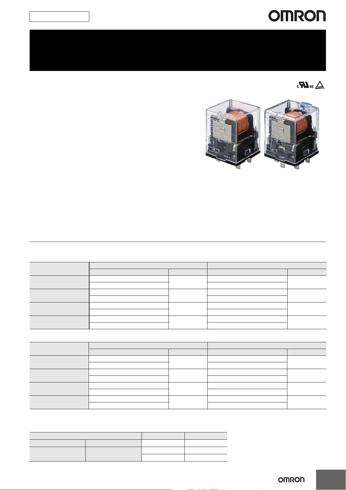
New Product
Power Relays
MK-S(X)
MK-S-series Relays with DC-switching
Models That Can Switch 220 VDC, 10 A
(Resistive Load).
• Switch a DC load of 220 VDC, 10 A (resistive load).
• Models for AC Loads can switch 250 VAC, 15 A (resistive load).
• Lineup includes models with SPST-NO and SPST-NO/SPSTNC contact forms.
• Using a SPST-NO/SPST-NC contact form enables detecting
contact welding. (When the NO contacts become welded, the
NC contacts will maintain a minimum distance of 0.5 mm.)
• Models available with operation indicators and built-in test
buttons.
• RoHS compliant.
• Standards: UL, IEC (TÜV certification)
(Application for the above standards has been made using the
P7MF-06 and P7MF-06-D Sockets (sold separately).)
Ordering Information
General-purpose Relays
Models for DC Loads
Contact form SPST-NO SPST-NO/SPST-NC
Type Rated coil voltage (V) Model Rated coil voltage (V) Model
Standard Models
Models with Built-in
Operation Indicators
Models with Test Button
Models with Test Button and
Built-in Operation Indicators
AC: 24, 100, 110, 120, 200, 220, 230, 240
DC: 12, 24, 48, 110, 220 DC: 12, 24, 48, 110, 220
AC: 24, 100, 110, 120, 200, 220, 230, 240
DC: 12, 24, 48, 110, 220 DC: 12, 24, 48, 110, 220
AC: 24, 100, 110, 120, 200, 220, 230, 240
DC: 12, 24, 48, 110, 220 DC: 12, 24, 48, 110, 220
AC: 24, 100, 110, 120, 200, 220, 230, 240
DC: 12, 24, 48, 110, 220 DC: 12, 24, 48, 110, 220
MKS1XT-10
MKS1XTN-10
MKS1XTI-10
MKS1XTIN-10
Models for AC Loads
Contact form SPST-NO SPST-NO/SPST-NC
Type Rated coil voltage (V) Model Rated coil voltage (V) Model
Standard Models
Models with Built-in
Operation Indicators
Models with Test Button
Models with Test Button and
Built-in Operation Indicators
AC: 24, 100, 110, 120, 200, 220, 230, 240
DC: 12, 24, 48, 110, 220 DC: 12, 24, 48, 110, 220
AC: 24, 100, 110, 120, 200, 220, 230, 240
DC: 12, 24, 48, 110, 220 DC: 12, 24, 48, 110, 220
AC: 24, 100, 110, 120, 200, 220, 230, 240
DC: 12, 24, 48, 110, 220 DC: 12, 24, 48, 110, 220
AC: 24, 100, 110, 120, 200, 220, 230, 240
DC: 12, 24, 48, 110, 220 DC: 12, 24, 48, 110, 220
MKS1T-10
MKS1TN-10
MKS1TI-10
MKS1TIN-10
AC: 24, 100, 110, 120, 200, 220, 230, 240
AC: 24, 100, 110, 120, 200, 220, 230, 240
AC: 24, 100, 110, 120, 200, 220, 230, 240
AC: 24, 100, 110, 120, 200, 220, 230, 240
AC: 24, 100, 110, 120, 200, 220, 230, 240
AC: 24, 100, 110, 120, 200, 220, 230, 240
AC: 24, 100, 110, 120, 200, 220, 230, 240
AC: 24, 100, 110, 120, 200, 220, 230, 240
MKS2XT-11
MKS2XTN-11
MKS2XTI-11
MKS2XTIN-11
MKS2T-11
MKS2TN-11
MKS2TI-11
MKS2TIN-11
Accessory (Order Separately)
Connecting Socket
Classifications Built-in diode Model
Back-connecting Socket PCB Terminals No P7M-06P
Front-connecting Socket
Mounts to DIN Track or via
screws
No P7MF-06
Yes P7MF-06-D
1
Page 2
MK-S(X)
Specifications
Ratings
Operating Coil
Item Rated current (mA)
Rated voltage (V) 50 Hz 60 Hz Percentage of rated voltage
24 110 96.3 48.4
100 26.6 23.1 760
110 24.2 21.0 932
AC
DC
120 22.2 19.3 1,130
200 13.3 11.6 3,160
220 12.1 10.5 3,550
230 11.5 10.0 4,250
240 11.0 9.6 4,480
12 126 95
24 63.2 380
48 32.0 1,500
110 13.6 8,060
220 6.8 32,200
Coil
resistance
(Ω)
Must
operate
voltage (V)
80% max.
Note: 1. The rated current and coil resistance are measured at a coil temperature of 23°C with tolerances of +15%/−20% for AC rated current and
±15% for DC coil resistance.
2. Performance characteristic data are measured at a coil temperature of 23°C.
3. The maximum allowable voltage is the maximum value of the allowable voltage range for the operating power supply for the relay coil.
There is no continuous allowance.
4. The rated current is approximately 5 mA higher for Models with Built-in Operation Indicators (DC operating coils).
Must
release
voltage (V)
30% min. at
60 Hz
25% min. at
50 Hz
15% min. Approx. 1.5 W
Maximum
voltage
allowable (V)
110%
Power
consumption
(VA, W)
Approx. 2.3 VA
at 60 Hz
Approx. 2.7 VA
at 50 Hz
2
Page 3
MK-S(X)
Contact Ratings for Models for DC Loads
Contact form SPST-NO SPST-NO/SPST-NC
Model MKS1XT(I)(N)-10 MKS2XT(I)(N)-11
Load
Item L/R = 7 ms DC13 class L/R = 7 ms DC13 class
Contact configuration
Contact material AgSnIn AgSnIn
Rated load
Rated carry current
Max. switching voltage
Max. switching current
Max. switching capacity
(reference value)
NO Double-break Double-break
NC --- Single-break
NO 10 A, 220 VDC 5 A, 220 VDC 0.4 A, 220 VDC 5 A, 220 VDC 3 A, 220 VDC 0.2 A, 220 VDC
NC --- 2 A, 220 VDC 0.3 A, 220 VDC 0.1 A, 220 VDC
NO 10 A 5 A
NC --- 2 A
NO 220 VDC
NC --NO 10 A 5 A
NC --- 2 A
NO 2,200 W --- --- 1,100 W --- --NC --- 440 W --- ---
Resistive load
Note: If the L/R of an inductive load exceeds 7 ms with a Model for a DC Load, the arc interruption time must be less than approximately 50 ms
to use the Relay. Design the circuit so that the arc interruption time is 50 ms or less.
* These values apply to a switching frequency of 30 times per minute.
Inductive load
Resistive load
Inductive load
220 VDC
Contact Ratings for Models for AC Loads
Contact form SPST-NO SPST-NO/SPST-NC
Model MKS1T(I)(N)-10 MKS2T(I)(N)-11
Load
Item
Contact configuration
Contact material AgSnIn AgSnIn
Rated load
Rated carry current
Max. switching voltage
Max. switching current
Max. switching capacity
(reference value)
NO Double-break Double-break
NC --- Single-break
NO 15 A, 250 VAC 15 A, 250 VAC
NC --- 5 A, 250 VAC
NO 15 A 15 A
NC --- 5 A
NO 250 VAC
NC --NO 15 A 15 A
NC --- 5 A
NO 3,750 VA 3,750 VA
NC --- 1,250 VA
* These values apply to a switching frequency of 20 times per minute.
Resistive load Resistive load
250 VAC
3
Page 4
MK-S(X)
Characteristics
Contact resistance *1 100 mΩ max.
Operate time *2
Release time *2 20 ms max.
Max. operating
frequency
Insulation resistance *3 100 MΩ min.
Dielectric
strength
Vibration
resistance
Shock
resistance
Endurance
Failure rate P level (reference value) 10 mA at 24 VDC
Ambient operating temperature
Ambient operating humidity 5% to 85%
Weight SPST-NO: Approx. 73 g, SPST-NO/SPST-NC: Approx. 82 g
Mechanical 18,000 operations/h
Rated load
Between coil and contacts 2,500 VAC 50/60 Hz for 1 min between
Between contacts of different polarity 2,500 VAC 50/60 Hz for 1 min between
Between contacts of same polarity 1,000 VAC 50/60 Hz for 1 min
Destruction 10 to 55 to 10 Hz, 0.50-mm single amplitude (1.0-mm double amplitude)
Malfunction 10 to 55 to 10 Hz, 0.75-mm single amplitude (1.5-mm double amplitude)
Destruction
Malfunction 100 m/s
Mechanical 1,000,000 operations min. (at 18,000 operations/hr)
Electrical *4 100,000 operations min. (at rated load and maximum switching frequency)
Note: The values given above are initial values.
*1. The contact resistance was measured for 1 A at 5 VDC using the voltage drop method.
*2. The operate time was measured with the rated voltage imposed and any contact bounce ignored at an ambient temperature of 23°C.
*3. The insulation resistance was measured with a 500-VDC insulation resistance tester at the same places as those used for checking the
dielectric strength.
*4. The electrical endurance was measured at an ambient temperature of 23°C.
AC: 20 ms max.
DC: 30 ms max.
Models for DC loads: 1,800 times/hour
Models for AC loads: 1,200 times/hour
Back-connecting Socket (P7M-06P) mounting: 1,000 m/s
Front-connecting Socket (P7MF-06(-D)) mounting:500m/s
2
−40°C to 60°C (with no icing or condensation)
Note: The range is −25°C to 60°C for models with built-in operation indicators.
2
2
Approved Standards
UL508 (File No. E41515)
Model Coil ratings Contact ratings
MKS1XT@-@
MKS2XT@-@
MKS1T@-@ NO contacts 15 A, 250 VAC (Resistive)
MKS2T@-@
12 to 220 VDC
24 to 240 VAC
NO contacts
NO contacts
NC contacts
NO contacts 15 A, 250 VAC (Resistive)
NC contacts
10 A, 220 VDC (Resistive)
5 A, 220 VDC L/R (T
0.4 A, 220 VDC L/R (T
5 A, 220 VDC (Resistive)
3 A, 220 VDC L/R (T
0.2 A, 220 VDC L/R (T
2 A, 220 VDC (Resistive)
0.3 A, 220 VDC L/R (T
0.1 A, 220 VDC L/R (T
5 A, 250 VAC (Resistive)
0.632) = 7 ms
0.95) = 300 ms
0.632) = 7 ms
0.95) = 300 ms
0.632) = 7 ms
0.95) = 300 ms
CSA Standard: CSA Certification by : CSA C22.2 No.14
IEC Standard/TÜV Certification: IEC61810-1 (Certification No. R50104853)
Model Coil ratings Contact ratings
MKS1XT@-@
12, 24, 48, 110,
MKS2XT@-@
MKS1T@-@ NO contacts AC-1: 15 A, 250 VAC 50/60 Hz
MKS2T@-@
220 VDC
24, 100, 110, 120,
200, 220, 230,
240 VAC
NO contacts
NO contacts
NC contacts
NO contacts AC-1: 15 A, 250 VAC 50/60 Hz
NC contacts
DC-1: 10 A, 220 VDC
5 A, 220 VDC L/R (T
DC-13: 0.4 A, 220 VDC
DC-1: 5 A, 220 VDC
3 A, 220 VDC L/R (T
DC-13: 0.2 A, 220 VDC
DC-1: 2 A, 220 VDC
0.3 A, 220 VDC L/R (T
DC-13: 0.1 A, 220 VDC
AC-1: 5 A, 250 VAC 50/60 Hz
0.632) = 7 ms
0.632) = 7 ms
0.632) = 7 ms
Operations
6,000
Operations
100,000
*
4
Page 5

Engineering Data
Maximum Switching Power
MKS1XT-10, MKS1XTN-10 MKS2XT-11, MKS2XTN-11
MKS1XTI-10, MKS1XTIN-10 MKS2XTI-11, MKS2XTIN-11
100
DC resistive load
10
5
Switching current (A)
1
0.4
0.1
0.01
DC inductive load
L/R = 7 ms
DC inductive load
DC13 class
100101 1.000
Switching voltage (V)
MKS1T-10, MKS1TN-10 MKS2T-11, MKS2TN-11
MKS1TI-10, MKS1TIN-10 MKS2TI-11, MKS2TIN-11
100
15
10
Switching current (A)
1
AC resistive load
100
DC resistive load
5
3
2
DC resistive load
1
L/R = 7 ms
DC resistive load
DC13 class
5
AC resistive load
1
NC
NO
NC
NO
10
Switching current (A)
0.3
0.2
0.1
0.01
100
15
10
Switching current (A)
DC resistive load
L/R = 7 ms
NO
DC resistive load
NC
DC resistive load
DC13 class
NC
Switching voltage (V)
AC resistive load
NO
100101 1.000
MK-S(X)
0.01
0.1
100101 1.000
Switching voltage (V)
0.01
0.1
100101 1.000
Switching voltage (V)
Ambient Temperature vs. Must Operate Voltage and Must Release Voltage
MKS2XT-11 MKS2XT-11
AC Specification (60 Hz) DC Specification
100
Number of Relays: 5
80
60
40
Must operate/release voltage (%)
20
Must operate
voltage
Must release
voltage
23-40 60
Ambient temperature (°C)
100
Number of Relays: 5
80
60
40
Must operate/release voltage (%)
20
Must operate
voltage
Must release
voltage
23-40 60
Ambient temperature (°C)
Inductive Load Switching Power (Models for DC Loads)
MKS1XT-10, MKS1XTN-10 MKS2XT-11, MKS2XTN-11
MKS1XTI-10, MKS1XTIN-10 MKS2XTI-11, MKS2XTIN-11
100
220 VDC
10
220 VDC
10
Switching current (A)
1
0.1
Load time constant (ms)
100 50 10 0 7
1
Switching current (A)
0.1
0.01
NC
NO
Load time constant (ms)
100 50 10 0 7
5
Page 6

MK-S(X)
e
Test Button
The circuit can be checked using either of two modes.
Test Button
DC specification: Blue
AC specification: Red
Normal
Mode 1
(momentary)
Mode 2
(locked)
Test Button Applications
Example: Checking operation of Relays and sequence circuits.
Press the button
for operation.
(No tool is required.)
Lock the contacts by
pressing down on th
button and turning it.
6
Page 7

MK-S(X)
Dimensions (Unit: mm)
General-purpose Relays
Models for DC Loads
Standard Models
MKS1XT-10 MKS2XT-11
Models with Built-in Operation Indicators
MKS1XTN-10 MKS2XTN-11
Models for AC Loads
Standard Models
MKS1T-10 MKS2T-11
Models with Built-in Operation Indicators
MKS1TN-10 MKS2TN-11
Models for DC Loads
Models with Test Button
MKS1XTI-10 MKS2XTI-11
Models with Test Button and Built-in
Operation Indicators
MKS1XTIN-10 MKS2XTIN-11
34.5 max.
34.5 max.
0.8
44 max.
7.3
3.5
34.5 max.
34.5 max.
Models for AC Loads
Models with Test Button
MKS1TI-10 MKS2TI-11
Models with Test Button and Built-in
Operation Indicators
MKS1TIN-10 MKS2TIN-11
Terminal Arrangement/Internal Connection (Bottom View)
MKS1XT-10
MKS1XTI-10
4
MKS1T-10
MKS1TI-10
DC specification AC specification DC specification AC specification
6 (
8
BA
4
+)
DC specification AC specification DC specification AC specification
8
MKS1XTN-10
MKS1XTIN-10
6 (+)
B (−)A (+)
MKS1TN-10
MKS1TIN-10
4
6 (+)
8
BA
MKS2XT-11
MKS2XTI-11
4
MKS2T-11
MKS2TI-11
44 max.
2
8 (+)
0.8
7.3
MKS2XTN-11
MKS2XTIN-11
2
6 (+)
BA
4
6 (+)
8 (+)
B (−)A (+)
MKS2TN-11
MKS2TIN-11
4
0.5
29.7
2
6 (+)
8 (+)
BA
2
4
Note: 1. Wire properly using the correct coil polarity.
2. The contact terminals on Models for DC Loads have polarity. Wire properly using the correct polarity.
6
8
BA
4
6
8
B (−)A (+)
4
6
8
BA
4
6
8
BA
2
4
6
8
B (−)A (+)
2
4
6
8
BA
7
Page 8

MK-S(X)
P7M-06P
P7MF-06
Connecting Socket
Back-connecting Socket
43 max.
39 max.
21.9
4.35
0.9
Dimensions
39 max.
22.1
Terminal Arrangement/Internal Connections
(Bottom View)
2
4
6
8
A
7.7
8.3
5.5
B
PCB Mounting Holes
(Bottom View)
5.5
8.3
0.9
7.7
Front-connecting Socket
P7MF-06-D
Dimensions
7
78 max.
34 max.
35.5
Terminal Arrangement/Internal Connections
P7MF-06
(TOP View)
P7MF-06-D
Mounting Holes
(TOP View)
Two, M4 or
two 3.5-dia. hole
66±0.3
8
39 max.
Six, M3 x 8
4
6
24.3
Note: 1. The internal connections diagram is for the MKS2(X)T@@-11.
2. The P7MF-06-D has polarity. Be careful to wire with the
correct polarity.
31±0.2
Page 9

Accessory (Order Separately)
Connecting Socket
Socket Back-connecting Socket Front-connecting Socket
Number of poles PCB terminals Mounts to DIN Track or via screws
P7M-06P P7MF-06
2
P7MF-06-D
MK-S(X)
Note: 1. The P7M-06P, P7MF-06, and P7MF-06-D can be used with models for DC loads with an SPST-NO or SPST-NO/SPST-NC contact form
or with models for AC loads with an SPST-NO or SPST-NO/SPST-NC contact form.
2. The P7MF-06-D has a built-in diode and can thus be used only with Relays with DC operating coils. Do not use it with a Relay with an
AC operating coil.
3. Refer to Gang Mounting on page 10 for the conditions required for gang mounting.
Relay Hold-down Clips
Use the Clips to securely mount the Relay and prevent it from falling due to vibration or shock.
Applicable Relay models MKS1XT-10
Socket
Back-connecting Socket PCB terminals P7M-06P
Front-connecting Socket
Mounts to DIN
Track or via
screws
P7MF-06
P7MF-06-D
Socket Mounting Height
P7M-06P
MKS1XTI-10
MKS1XTIN-10
MKS1T-10
MKS1TI-10
MKS1TIN-10
PYC-A2
MKS2XT-11
MKS2XTI-11
MKS2XTIN-11
MKS2T-11
MKS2TI-11
MKS2TIN-11
PYC-A2
One Set (Two Clips)
5 max.
42.8
4.5 1.2
Note: The minimum order for the
PYC-A2 is ten clips.
4.5
P7MF-06
P7MF-06-D
64 61
70
74
MK-S(X)
MK-S(X)
75
79
9
Page 10

MK-S(X)
Safety Precautions
Refer also to Precautions for All Relays.
Precautions for Correct Use
Installation
• Models for DC loads (i.e., models with “X” in the model number)
have permanent magnets built into the insulating block. If a
permanent magnet or other magnetic body comes near the Relay,
magnetic interference will occur with the built-in permanent magnet
and the contact switching capacity will be decreased.
• Models for AC loads do not contain a permanent magnet.
• When mounting a P7MF-06(-D) Front-mounting Socket to a DIN
Track, attach PFP-M End Plates on both sides of the Socket to
prevent it from moving.
Gang Mounting
Conditions for Gang Mounting Relays
Socket
Relay
Models for
DC Loads
Models for
AC Loads
* Gang mounting of the Front-Mounting Sockets is not possible if the
contact carry current exceeds 10A.Provide space on both the right
and left sides of the Sockets.
The mounting pitch is given in the following diagram.
20
15
Applied current (A)
10
Rated current
of Relay
10A ❍❍
15A ❍ *
Back-Connecting
Socket
Front-Connecting
Socket
Test Button
• Turn OFF the power supply before operating the test button.
Always return the test button to the original position after you use it.
• Do not use the test button as a switch.
• The durability of the test button is 100 operations minimum.
Operating Environment
Do not use the Relay in environments with combustible gas. Doing so
may result in explosion due to arcing.
Storage
Models for DC Loads (i.e., models with “X” in the model number) are
magnetized because they have a built-in magnet to deflect and
extinguish the arc. Do not install the Relay near IC cards or other
items that may be adversely affected by magnetism.
Usage
Use the Relay mounted in the P7M-06P or P7MF-06(-D) Socket.
5
0
0 10 20 30 40 50
Mounting interval (mm)
Mounting interval
Wiring
• The contact terminals on Models for DC Loads (i.e., models with
“X” in the model number) have polarity. Wiring with incorrect
polarity may result in inability to turn OFF the Relay or loss of
functionality.
• Wire models with built-in operation indicators with the correct coil
polarity (DC operating coil).
10
Page 11

MK-S(X)
Warranty and Application Considerations
Read and Understand this Catalog
Please read and understand this catalog before purchasing the products. Please consult your OMRON representative if you
have any questions or comments.
Warranty and Limitations of Liability
WARRANTY
OMRON's exclusive warranty is that the products are free from defects in materials and workmanship for a period of one year (or
other period if specified) from date of sale by OMRON.
OMRON MAKES NO WARRANTY OR REPRESENTATION, EXPRESS OR IMPLIED, REGARDING NON-INFRINGEMENT,
MERCHANTABILITY, OR FITNESS FOR PARTICULAR PURPOSE OF THE PRODUCTS. ANY BUYER OR USER
ACKNOWLEDGES THAT THE BUYER OR USER ALONE HAS DETERMINED THAT THE PRODUCTS WILL SUITABLY MEET
THE REQUIREMENTS OF THEIR INTENDED USE. OMRON DISCLAIMS ALL OTHER WARRANTIES, EXPRESS OR
IMPLIED.
LIMITATIONS OF LIABILITY
OMRON SHALL NOT BE RESPONSIBLE FOR SPECIAL, INDIRECT, OR CONSEQUENTIAL DAMAGES, LOSS OF PROFITS,
OR COMMERCIAL LOSS IN ANY WAY CONNECTED WITH THE PRODUCTS, WHETHER SUCH CLAIM IS BASED ON
CONTRACT, WARRANTY, NEGLIGENCE, OR STRICT LIABILITY.
In no event shall the responsibility of OMRON for any act exceed the individual price of the product on which liability is asserted.
IN NO EVENT SHALL OMRON BE RESPONSIBLE FOR WARRANTY, REPAIR, OR OTHER CLAIMS REGARDING THE
PRODUCTS UNLESS OMRON'S ANALYSIS CONFIRMS THAT THE PRODUCTS WERE PROPERLY HANDLED, STORED,
INSTALLED, AND MAINTAINED AND NOT SUBJECT TO CONTAMINATION, ABUSE, MISUSE, OR INAPPROPRIATE
MODIFICATION OR REPAIR.
Application Considerations
SUITABILITY FOR USE
OMRON shall not be responsible for conformity with any standards, codes, or regulations that apply to the combination of
products in the customer's application or use of the products.
Take all necessary steps to determine the suitability of the product for the systems, machines, and equipment with which it will
be used.
Know and observe all prohibitions of use applicable to this product.
NEVER USE THE PRODUCTS FOR AN APPLICATION INVOLVING SERIOUS RISK TO LIFE OR PROPERTY WITHOUT
ENSURING THAT THE SYSTEM AS A WHOLE HAS BEEN DESIGNED TO ADDRESS THE RISKS, AND THAT THE OMRON
PRODUCTS ARE PROPERLY RATED AND INSTALLED FOR THE INTENDED USE WITHIN THE OVERALL EQUIPMENT OR
SYSTEM.
Disclaimers
PERFORMANCE DATA
Performance data given in this catalog is provided as a guide for the user in determining suitability and does not constitute a
warranty. It may represent the result of OMRON's test conditions, and the users must correlate it to actual application
requirements. Actual performance is subject to the OMRON Warranty and Limitations of Liability.
CHANGE IN SPECIFICATIONS
Product specifications and accessories may be changed at any time based on improvements and other reasons. Consult with
your OMRON representative at any time to confirm actual specifications of purchased product.
DIMENSIONS AND WEIGHTS
Dimensions and weights are nominal and are not to be used for manufacturing purposes, even when tolerances are shown.
11
Page 12

OMRON Corporation
Industrial Automation Company
Control Devices Division H.Q.
Strategy Planning Division
Shiokoji Horikawa, Shimogyo-ku,
Kyoto, 600-8530 Japan
Tel: (81) 75-344-7109/Fax: (81) 75-344-7149
Regional Headquarters
OMRON EUROPE B.V.
Wegalaan 67-69-2132 JD Hoofddorp
The Netherlands
Tel: (31)2356-81-300/Fax: (31)2356-81-388
OMRON ELECTRONICS LLC
One Commerce Drive Schaumburg,
IL 60173-5302 U.S.A.
Tel: (1) 847-843-7900/Fax: (1) 847-843-7787
OMRON ASIA PACIFIC PTE. LTD.
No. 438A Alexandra Road # 05-05/08 (Lobby 2),
Alexandra Technopark, Singapore 119967
Tel: (65) 6835-3011/Fax: (65) 6835-2711
OMRON (CHINA) CO., LTD.
Room 2211, Bank of China Tower,
200 Yin Cheng Zhong Road,
PuDong New Area, Shanghai, 200120, China
Tel: (86) 21-5037-2222/Fax: (86) 21-5037-2200
OMRON Industrial Automation Global: www.ia.omron.com
Authorized Distributor:
© OMRON Corporation 2008 All Rights Reserved.
In the interest of product improvement,
specifications are subject to change without notice.
Cat. No. J175-E1-02
Printed in Japan
0809
 Loading...