

Page 1
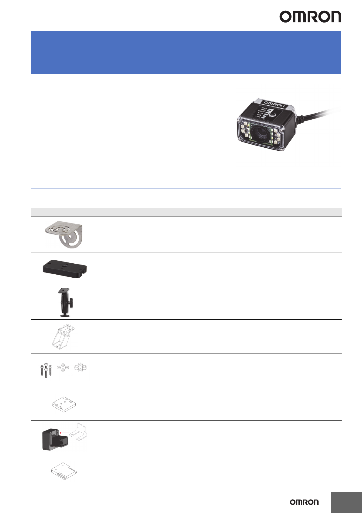
MicroHAWK F420-F
Smart Camera
World’s smallest fully-integrated vision system.
• Simple configuration with AutoVISION.
• 5 megapixel sensor available.
• Autofocus available.
• Serial RS-232, USB, or Ethernet over USB.
• IP54.
• Corner-exit cable.
MicroHAWK F420-F
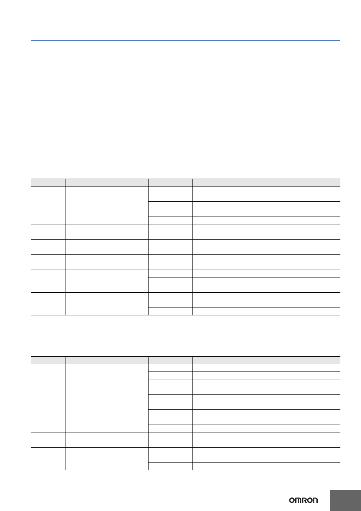
Mounting Options
Appearance Type Part Number
L Bracket Adjustable Angle Mounting Kit V430-AM0
¼-20 Camera Mounting Block Kit V430-AM1
4” (102 mm) Ram Mount Stand V430-AM2
APG Pan and Tilt Camera Mount V430-AM3
Nylon Screw and Washer Electrical Isolation Mounting Kit V430-AM4
MS-4 / MINI to V/F4XX-F Adapter Plate V430-AM5
Smart Ring Light to V/F4XX-F Mounting Bracket V430-AM6
QX / Vision HAWK to V/F4XX-F Adapter Plate V430-AM7
1
Page 2
F420-F
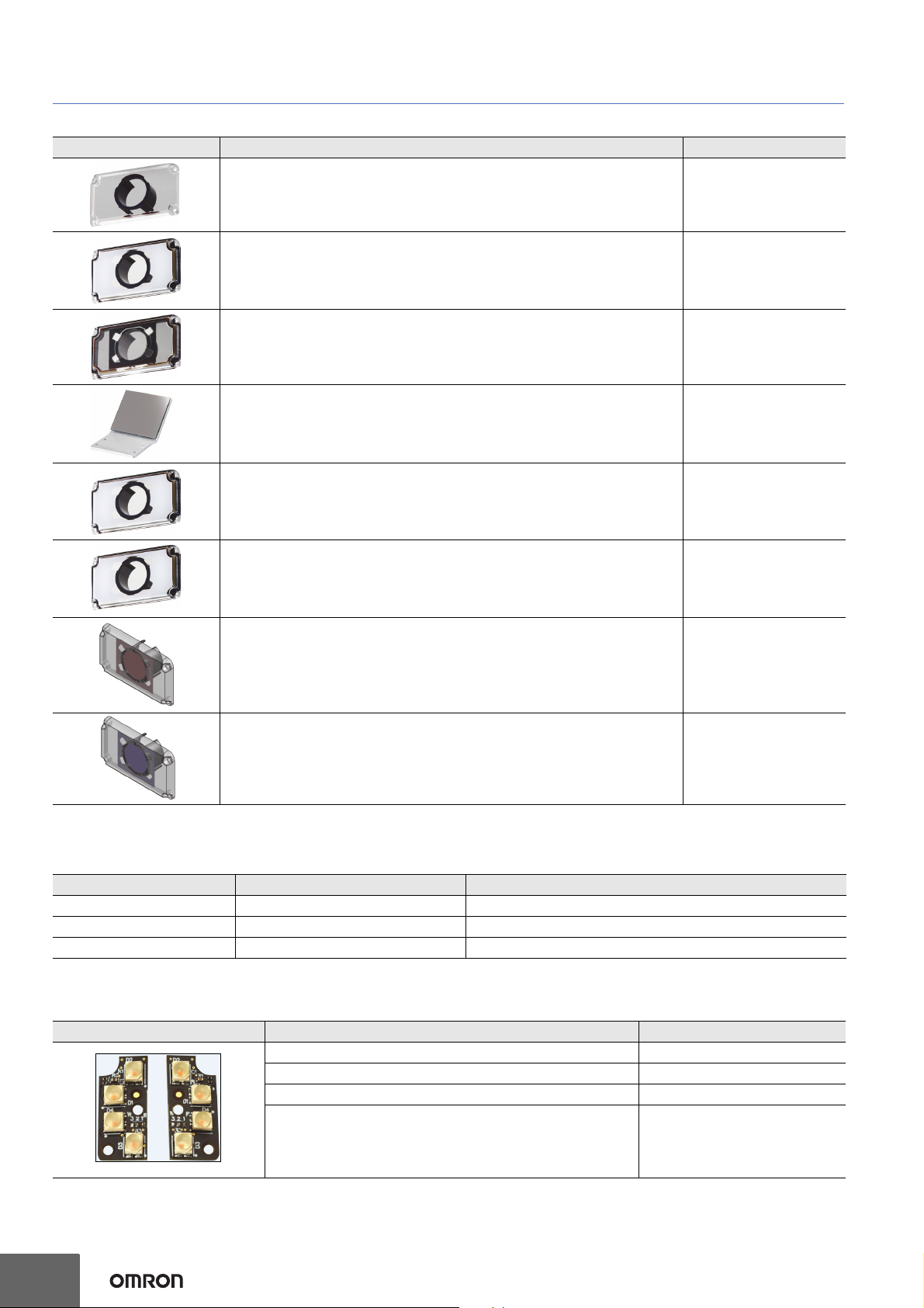
Optics Options
Appearance Type Part Number
Front Window - Installation Kit V430-AF10 *
Diffuser – Installation Kit V430-AF11 *
Polarizer – Installation Kit V430-AF12
Right Angle Mirror - Installation Kit V430-AF3
YAG Filter - Installation Kit V430-AF4
ESD-Safe Window - Installation Kit V430-AF5
Red Filter - Installation Kit V430-AF6
Blue Filter - Installation Kit V430-AF7
*
* Note: V430-AF10, AF11, and AF12 are used for MicroHAWK V/F4X0-FXXXXXXX-XXX cameras in this datasheet. The prior generation
MicroHAWK V430-FXXXXXXX code reader uses part numbers V430-AF0, AF1, and AF2. Please select the correct accessory from the table
based on your camera part number format.
Accessory Prior V430-FXXXXXXX Code Reader New V/F4X0-FXXXXXXX-XXX Code Reader and Smart Camera
Front Window Installation Kit V430-AF0 V430-AF10
Diffuser Installation Kit
Polarizer Installation Kit V430-AF2 V430-AF12
V430-AF1 V430-AF11
Lighting Options
Appearance Type Part Number
Red Light - Installation Kit V430-ALR
White Light - Installation Kit
Blue Light - Installation Kit V430-ALB
IR Light - Installation Kit V430-ALI
V430-ALW
2
Page 3
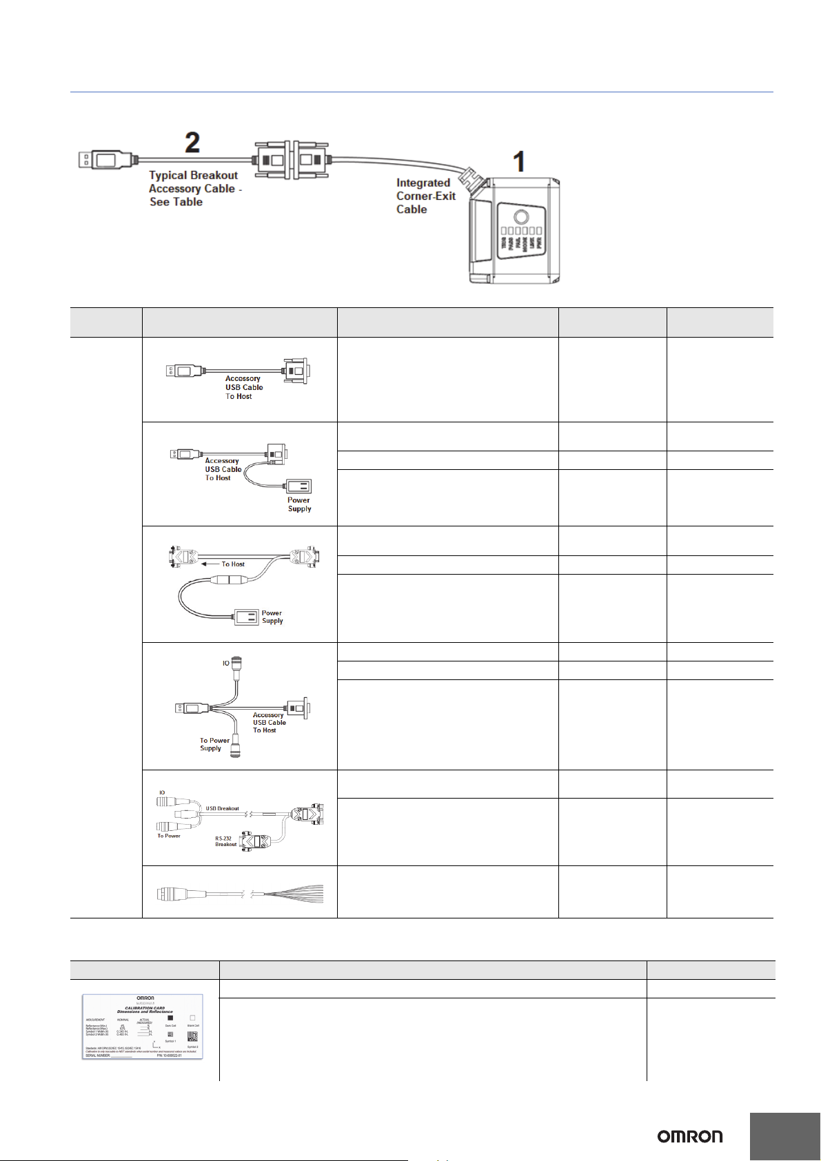
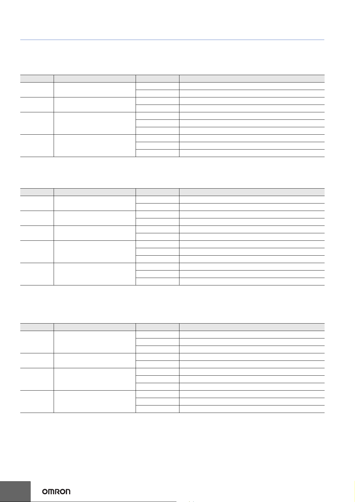
Wiring Options
2
F420-F
Drawing
Reference
Appearance Category Length / Spec Part Number
USB Breakout Cable 1 Meter V420-WUB-1M
Cable - USB Breakout With External Power
Input
Power Supply 2 Meters 97-9000006-01
Kit – Cable and Power Supply V420-AC1
Cable – RS-232 Breakout (DB-15) and
External Power Input
Power Supply 2 Meters 97-9000006-01
Kit – Cable and Power Supply V420-AC0
Cable – USB, IO, and Power Breakout 1 Meter V420-WU8X-1M
Power Supply 2 Meters 97-000011-02
1 Meter V420-WUX-1M
1 Meter V420-WRX-1M
Verification Options
Appearance Type Part Number
Kit – Cable and Power Supply V420-AC2
Cable – RS-232, USB, IO, and Power
Breakout
Power Supply 2 Meters 97-000011-02
Cable – Trigger, IO, and Power Breakout 900 MM 61-000151-01
AutoVISION Verification Calibration Card with NIST-Traceable Measurement Report 98-000265-01
AutoVISION Verification Calibration Card 98-000265-02
1 Meter V420-WRU8X-1M
3
Page 4
F420-F
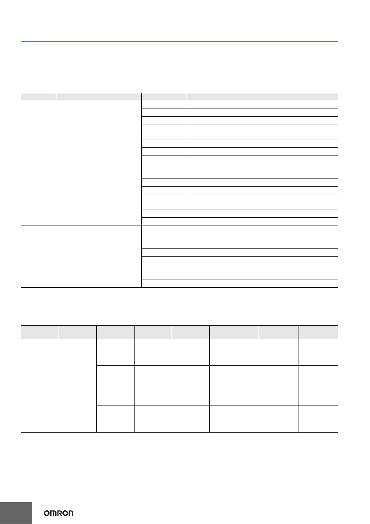
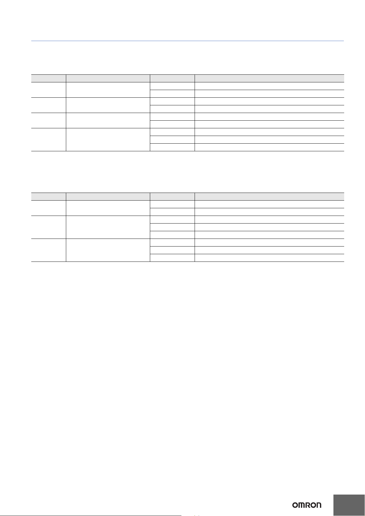
F420-F Part Number Structure
Use this legend when defining product part numbers. Please note that not all combinations of parameters are valid. For instance, color cameras
are only available with white lighting, and 400 mm fixed focus is only available with UHD lenses. When ordering, use valid part numbers from the
tables in the Ordering Information section only.
F420-F[XXX][Y][ZZZ]-[L][C][P]
Key Classification Code Meaning
XXX Focus Distance (mm) 000 Autofocus – Variable Distance
050 Fixed Focus at 50 mm
064 Fixed Focus at 64 mm
081 Fixed Focus at 81 mm
102 Fixed Focus at 102 mm
133 Fixed Focus at 133 mm
190 Fixed Focus at 190 mm
300 Fixed Focus at 300 mm
400 Fixed Focus at 400 mm
Y Lens W Wide Field of View – 5.2 mm Focal Length Lens
M Medium Field of View – 7.7 mm Focal Length Lens
N Narrow Field of View – 16 mm Focal Length Lens
L Narrow 16 mm Lens – Autofocus to 1160 mm
ZZZ Sensor 03M 752 x 480 (0.3 MP) Pixel, Mono Sensor, Global Shutter
12M 1280 x 960 (1.2 MP) Pixel, Mono Sensor, Global Shutter
50C 2592 x 1944 (5 MP) Pixel, Color Sensor, Rolling Shutter
L Light Type N No Outer Light
S Standard Outer Light
C Light Color N No Outer Light
RRed
WWhite
P Software License S AutoVISION Sensor (Vision Toolset Only)
A AutoVISION (Vision and Code Reading / Verification Toolsets)
V Visionscape (Full AutoVISION and Visionscape Toolsets)
Example Part Numbers:
• F420-F081W03M-NNS: Fixed Focus at 81 mm, Wide Lens, 0.3 MP Monochrome Sensor, No Outer Light, AutoVISION Sensor
F420-F Valid Product Matrix
Model Category Focus Type Sensor Lens
03M, 12M W, M 50, 81, 102, 190, 300
Fixed Focus
12M N 64, 400
F420-F
Monochrome
Color
Specialty
Autofocus
Fixed Focus 50C W, M 50, 81, 102, 190, 300 None, White S, A, V
Autofocus 50C W, M
Long Range
Autofocus
03M W, M
12M W, M, N
12M L
Focus Distance
(mm)
50 <-> 300
Autofocus
50 <-> 300 (W, M)
40 <-> 150 (N)
Autofocus
50 <-> 300
Autofocus
75 <->1160
Autofocus
Light License
None, Red,
White
None, Red,
White
None, Red,
White
None, Red,
White
None, White S, A, V
None, Red,
White
S, A, V
S, A, V
S, A, V
S, A, V
S, A, V
4
Page 5
F420-F Ordering Information
Categories:
1. Fixed Focus Camera
a.) F420-F Monochrome Fixed Focus Camera
b.) F420-F Color Fixed Focus Camera
c.) F420-F 1.2 MP Monochrome Fixed Focus Camera with Narrow Lens
2. Autofocus Camera
a.) F420-F 0.3 MP Monochrome Autofocus Camera (50 – 300 mm)
b.) F420-F 1.2 MP Monochrome Autofocus Camera (50 – 300 mm for Wide and Medium Lens, 40 – 150 mm for
Narrow Lens)
c.) F420-F Color Autofocus Camera (50 - 300 mm)
d.) F420-F 1.2 MP Monochrome Long Range Autofocus Camera (75 - 1160 mm)
1a) F420-F Monochrome Fixed Focus Camera: Valid Combinations
F420-F[XXX][Y][ZZZ]-[L][C][P]
Key Classification Code Meaning
XXX Focus Distance (mm) 050 Fixed Focus at 50 mm
064 Fixed Focus at 64 mm
081 Fixed Focus at 81 mm
102 Fixed Focus at 102 mm
300 Fixed Focus at 300 mm
Y Lens W Wide Field of View - 5.2 mm Focal Length Lens
M Medium Field of View – 7.7 mm Focal Length Lens
ZZZ Sensor 03M 752 x 480 (0.3 MP) Pixel, Mono Sensor, Global Shutter
12M 1280 x 960 (1.2 MP) Pixel, Mono Sensor, Global Shutter
L Light Type N No Outer Light
S Standard Outer Light
C Light Color N No Outer Light
RRed
WWhite
P Software License S AutoVISION Sensor (Vision Toolset Only)
A AutoVISION (Vision and Code Reading / Verification Toolsets)
V Visionscape (Full AutoVISION and Visionscape Toolsets)
F420-F
1b) F420-F 5.0 MP Color Fixed Focus Camera: Valid Combinations
Note: 5 MP Color cameras are available with No or White light options only.
F420-F[XXX][Y]50C-[L][C][P]
Key Classification Code Meaning
XXX Focus Distance (mm) 050 Fixed Focus at 50 mm
064 Fixed Focus at 64 mm
081 Fixed Focus at 81 mm
102 Fixed Focus at 102 mm
300 Fixed Focus at 300 mm
Y Lens W Wide Field of View - 5.2 mm Focal Length Lens
M Medium Field of View – 7.7 mm Focal Length Lens
L Light Type N No Outer Light
S Standard Outer Light
C Light Color N No Outer Light
WWhite
P Software License S AutoVISION Sensor (Vision Toolset Only)
A AutoVISION (Vision and Code Reading / Verification Toolsets)
V Visionscape (Full AutoVISION and Visionscape Toolsets)
5
Page 6
F420-F
1c) F420-F 1.2 MP Monochrome Fixed Focus Camera with Narrow Lens: Valid Combinations
Note: Fixed Focus Narrow lens option available for 1.2 MP Mono camera only.
F420-F[XXX]N12M-[L][C][P]
Key Classification Code Meaning
XXX Focus Distance (mm) 064 Fixed Focus at 64 mm
400 Fixed Focus at 400 mm
L Light Type N No Outer Light
S Standard Outer Light
C Light Color N No Outer Light
RRed
WWhite
P Software License S AutoVISION Sensor (Vision Toolset Only)
A AutoVISION (Vision and Code Reading / Verification Toolsets)
V Visionscape (Full AutoVISION and Visionscape Toolsets)
2a) F420-F 0.3 MP Monochrome Autofocus Cameras (50 – 300 mm): Valid Combinations
F420-F000[Y]03M-[L][C][P]
Key Classification Code Meaning
Y Lens W Wide Field of View - 5.2 mm Focal Length Lens
M Medium Field of View – 7.7 mm Focal Length Lens
ZZZ Sensor 03M 752 x 480 (0.3 MP) Pixel, Mono Sensor, Global Shutter
12M 1280 x 960 (1.2 MP) Pixel, Mono Sensor, Global Shutter
L Light Type N No Outer Light
S Standard Outer Light
C Light Color N No Outer Light
RRed
WWhite
P Software License S AutoVISION Sensor (Vision Toolset Only)
A AutoVISION (Vision and Code Reading / Verification Toolsets)
V Visionscape (Full AutoVISION and Visionscape Toolsets)
2b) F420-F 1.2 MP Monochrome Autofocus Camera (50 – 300 mm for Wide and Medium, 40 – 150 mm for
Narrow): Valid Combinations
F420-F000[Y]12M-[L][C][P]
Key Classification Code Meaning
Y Lens W Wide Field of View - 5.2 mm Focal Length Lens
M Medium Field of View – 7.7 mm Focal Length Lens
N Narrow Field of View – 16 mm Focal Length Lens
L Light Type N No Outer Light
S Standard Outer Light
C Light Color N No Outer Light
RRed
WWhite
P Software License S AutoVISION Sensor (Vision Toolset Only)
A AutoVISION (Vision and Code Reading / Verification Toolsets)
V Visionscape (Full AutoVISION and Visionscape Toolsets)
6
Page 7
F420-F
2c) F420-F 5.0 MP Color Autofocus Camera (50 - 300 mm): Valid Combinations
Note: Narrow Autofocus lens option not available for color camera.
F420-F000[Y]50C-[L][C][P]
Key Classification Code Meaning
Y Lens W Wide Field of View - 5.2 mm Focal Length Lens
M Medium Field of View – 7.7 mm Focal Length Lens
L Light Type N No Outer Light
S Standard Outer Light
C Light Color N No Outer Light
WWhite
P Software License S AutoVISION Sensor (Vision Toolset Only)
A AutoVISION (Vision and Code Reading / Verification Toolsets)
V Visionscape (Full AutoVISION and Visionscape Toolsets)
2d) F420-F 1.2 MP Monochrome Long Range Autofocus Camera (75 - 1160 mm): Valid Combinations
Note: Autofocus Long Range lens option available for 1.2 MP Monochrome camera only.
F420-F000L12M-[L][C][P]
Key Classification Code Meaning
L Light Type N No Outer Light
S Standard Outer Light
C Light Color N No Outer Light
RRed
WWhite
P Software License S AutoVISION Sensor (Vision Toolset Only)
A AutoVISION (Vision and Code Reading / Verification Toolsets)
V Visionscape (Full AutoVISION and Visionscape Toolsets)
7
Page 8

F420-F
Field of View
Maximum Depth
of Field (Outside)
Maximum Depth
of Field (Inside)
Reading
Ranges
Reading Distance
Field of View Charts
ifications are subject to change.
Spec
Fixed Focus Field of View (mm) - Wide Lens
0.3 MP 1.2 MP 5 MP
Distance (mm) Width Height Width Height Width Height
50 49 32 53 39 50 38
81 76 49 81 61 78 58
102 95 60 101 75 96 72
190 171 109 182 136 174 130
300 266 170 283 213 271 202
Fixed Focus Field of View (mm) - Medium Lens
0.3 MP 1.2 MP 5 MP
Distance (mm) Width Height Width Height Width Height
50 34 22 36 27 35 26
81 53 34 56 42 54 40
102 66 42 70 52 67 50
190 119 76 126 95 121 90
300 185 118 196 147 188 140
Fixed Focus Field of View (mm) - Narrow Lens
1.2 MP
Distance (mm) Width Height
64 21 15
400 118 88
8
Page 9

Autofocus Field of View (mm) - Wide Lens
0.3 MP 1.2 MP 5 MP
Distance (mm) Width Height Width Height Width Height
50 51 33 55 41 52 39
100 97 62 103 77 98 73
150 142 90 151 113 144 107
200 187 119 199 149 190 142
250 232 148 247 185 236 176
300 277 177 295 221 282 210
Autofocus Field of View (mm) - Medium Lens
0.3 MP 1.2 MP 5 MP
Distance (mm) Width Height Width Height Width Height
50 33 21 36 27 34 25
100 63 40 67 50 64 48
150 92 59 98 73 94 70
200 121 77 129 97 123 92
250 151 96 160 120 153 114
300 180 115 191 144 183 136
F420-F
Autofocus Field of View (mm) - Narrow Lens
1.2 MP
Distance (mm) Width Height
50 16 12
100 31 23
150 45 34
Long Range Autofocus Field of View (mm)
1.2 MP
Distance (mm) Width Height
75 24 18
100 31 23
200 60 45
300 89 67
400 118 88
500 147 110
600 176 132
700 204 153
800 233 175
900 262 197
1000 291 218
1200 349 262
1300 378 283
1400 407 305
1500 436 327
9
Page 10

F420-F
Pitch angle
Skew angle Tilt angle
Ratings and Specifications
F420-F F420-F□□□□03M-□□□ F420-F□□□□12M-□□□ F420-F□□□□50C-□□□
1D Symbologies
Symbologies *1
Reading
Performance
Vision Tools
Image Capture
Image Logging FTP
Trigger External Trigger (Edge or Level), Communication Trigger (Ethernet, RS-232C)
I/O Specifications
Communication
Indicator LEDs PASS (Green), TRIG (Amber), MODE (Amber), LINK (Amber), FAIL (Red), PWR (Green)
Power Supply Voltage 5 VDC +/- 5%
Current Consumption 650 mA at 5 VDC (max.)
Environmental
Immunity
Weight
Dimensions
Accessories ReadMeFirst, CE Compliance Sheet
LED Safety Standard IEC 62471-1: 2006 Risk-Exempt Group
Safety Standards
Materials
Software AutoVISION, Visionscape FrontRunner
*1. These symbologies are supported based on Omron’s read capability validation standard. Omron recommends that validation be performed for each application.
*2. Unless otherwise specified, reading performance is defined with center of field of view, angle R=
*3.
*4
2D Symbologies Data Matrix (ECC 0-200), QR Code, Micro QR Code, Aztec Code, DotCode, DMRE
Stacked Symbologies PDF417, MicroPDF417, GS1 Databar (Composite and Stacked)
Number of Reading Digits No Upper Limit (depending on bar width and reading distance)
Aiming Light Two Blue LEDs
Illumination
*2
Reading Distance /
Field of View
Pitch Angle (α) *3 ±30°
Skew Angle (β) *3 ±30°
Tilt Angle (γ) *3 ±180°
Focus Liquid Lens Autofocus or Fixed Focus (Wide = 5.2 mm, Medium = 7.7 mm, Narrow = 16 mm, L = 16 mm)
Resolution 752 (H) x 480 (V) 1280 (H) x 960 (V) 2592 (H) x 1944 (V)
Color /
Monochrome
Shutter Global Shutter Global Shutter Rolling Shutter
Frames per Second 52 fps 40 fps 5 fps
Exposure 50 to 66,667 μs 50 to 58,825 μs 50 to 66,667 μs
Input Signals
Output Signals 3 Signals : 5 V TTL-compatible, can sink 10 mA and source 10 mA
Connectivity RS-232C, USB 2.0 High Speed, Ethernet over USB/HID
Ethernet Specifications 100BASE-TX / 10BASE-T
Ambient Temperature
Range
Ambient Humidity Range Operating and storage: 5% to 95% (Non-Condensing)
Ambient Atmosphere No Corrosive Gases
Vibration Resistance
(Destructive)
Shock Resistance
(Destructive)
Degree of Protection IEC 60529 IP54
Main Body Only 120 g
Packaging Weight Approx. 230 g (including packing)
Main Body Dimensions 44.5 (W) × 38.1 (D) × 25.4 (H) mm
Packaging Dimensions 170 (W) × 117 (D) × 86 (H) mm
Case Aluminum Diecast, Alumite (Black)
Reading Window Acrylic
Code 39, Code 128, BC412, Interleaved 2 of 5, UPC/EAN, Codabar, Code 93, Pharmacode, PLANET,
Postnet, Japanese Post, Australian Post, Royal Mail, Intelligent Mail, KIX
Inner LEDs: Four White and Four Red (Wavelength: 625 nm)
Outer LEDs:
8 Red or White
Refer to Field of View Charts for details.
Locate, Decode, Optical Character Recognition (OCR), Count, Presence/Absence, Measure, Match Strings,
String Format, Logic, Optical Character Verification (OCV), Symbol Quality Verification, Color Identification,
Color Match
Monochrome CMOS Monochrome CMOS Color CMOS
Trigger Input: 5-28 V rated (0.16 mA @ 5 VDC); New Master: 5 to 28 V rated (0.16 mA @ 5 VDC); Default:
3.3 V rated (0 mA @ 3.3 V)
Operating: 0 to 45° C Storage: -50 to 75° C (No Icing or Condensation)
Sine Vibration: 10 Hz to 55 Hz, 0.35mm displacement, 20 cycles/axis. Random Vibration: 20 Hz to 2000 Hz,
6.295 Grms, 30 min/axis
50 G, 11 ms, sawtooth profile. 3X in each X, Y, Z axis.
EN 61326-1:2013
FCC Part 15, Subpart B (Class B) UL60950-1
RCM, KC, EAC
Outer LEDs:
8 Red or White
Outer LEDs:
8 White
∞.
*4. In an electrically noisy environment, use only the F430-F in combination with a noise filter cable (V430-W
10
□F-□M) to ensure proper operation.
Page 11

F420-F
L Bracket Adjustable Angle Mounting Kit
V430-AM0
¼-20 Camera Mounting Block Kit
V430-AM1
Dimensions (Unit: mm)
11
Page 12

F420-F
4” (102 mm) Ram Mount Stand
V430-AM2
APG Pan and Tilt Camera Mount
V430-AM3
MS-4 / MINI to V/F4XX-F Adapter Plate
V430-AM5
12
Page 13

Smart Ring Light to V/F4XX-F Mounting Bracket
V430-AM6
F420-F
QX / Vision HAWK to V/F4XX-F Adapter Plate
V430-AM7
13
Page 14

F420-F
Front Window Installation Kit
V430-AF10
*
Diffuser Installation Kit
V430-AF11
*
Polarizer Installation Kit
V430-AF12
*
* Note: V430-AF10, AF11, and AF12 are used for MicroHAWK V/F4X0-FXXXXXXX-XXX cameras in this manual. The prior generation
MicroHAWK V430-FXXXXXXX code camera uses part numbers V430-AF0, AF1, and AF2. Please select the correct accessory from the
table based on your camera part number format.
Accessory Prior V430-FXXXXXXX Code Reader
New V/F4X0-FXXXXXXX-XXX Code Reader and
Smart Camera
Front Window Installation Kit V430-AF0 V430-AF10
Diffuser Installation Kit
V430-AF1 V430-AF11
Polarizer Installation Kit V430-AF2 V430-AF12
Right Angle Mirror Installation Kit
V430-AF3
14
Page 15

F420-F
YAG Laser Filter Window
V430-AF4
ESD-Safe Window
V430-AF5
Window Material
Polymer
Laser Type
Argon
Broadband
KTP
Nd:YAG
Protection
OD 6+ @ 200-532 nm
OD 4+ @ 850-879 nm
OD 5+ @ 900-1070 nm
The V430-AF4 YAG Laser Filter is used to block a range of wavelengths from a variety of laser types
from being seen by the MicroHAWK camera that will either disrupt the cameras view of the object,
or damage the MicroHAWK sensor.
The table shows the laser types that are handled by the V430-AF4 Filter window, as well as the level
of protection they provide at the various wavelengths.
Note: Optical Density (OD) is a measure of the attenuation of energy passing through a filter. The
higher the OD value, the higher the attenuation and the greater the protection level.
OD 4 blocks 99.99% of the laser energy.
OD 5 blocks 99.999% of the laser energy (YAG).
OD 6 blocks 99.9999% of the laser energy (Argon, KTP)
An ESD event occurs when an electrostatic charge rapidly transfers between two objects. This
transfer is usually caused when two objects with a notable potential difference in electrical charge
contact each other. However, ESD events can also happen when two objects close to one another
create a highly charged electrostatic field.
ESD safety precautions are extremely important in the electronics and semiconductor industries
where sensitive components can be damaged even by a discharge of a mere 20 volts. Less
sensitive components may still be susceptible, and cumulative discharges can create long-term
problems affecting the functionality and performance of electronic components.
The MicroHAWK V430-AF5 ESD-Safe window is designed with an ESD coating on the exterior
surface to prevent static discharge between the camera or smart camera when the camera is
deployed close to the component surface. The antistatic coating offers a resistivity of ≤ 1.0 X 10^9 Ω/
sq
to prevent these electrostatic discharges.
15
Page 16

F420-F
Red Filter Installation Kit
V430-AF6
Blue Filter Installation Kit
V430-AF7
Red Light Installation Kit
V430-ALR
White Light Installation Kit
V430-ALW
Blue Light Installation Kit
V430-ALB
IR Light Installation Kit
V430-ALI
Red Filter (V430-AF6) and Blue Filter (V430-AF7)
The Red Filter (V430-AF6), and Blue Filter (V430-AF7) are used to turn MicroHAWKs equipped
with white lights into units that emit red or blue light. MicroHAWK light color changes can be also
be accomplished using the F430-F Red, Blue, White, or IR LED kits.
A typical example of how to use different color filters or LEDs with monochrome cameras is
shown below. The emitted color is matched with the color of the part that needs to be
emphasized or de-emphasized, which creates sufficient contrast for the part to be inspected or
for the symbol to be decoded. In the example below, the red filter makes the reddish copper look
bright, while the green circuit board looks dark. The blue filter produces the opposite effect.
16
Page 17

F420-F
USB Breakout Cable – 1 Meter
V420-WUB-1M
17
Page 18

F420-F
Kit – USB Breakout Cable with External Power Input (1 Meter) and Power Supply (1 Meter)
V420-AC1
18
Page 19

F420-F
Kit – RS-232 Breakout Cable (DB-15) with External Power Input (1 Meter) and Power Supply (1 Meter)
V420-AC0
19
Page 20

F420-F
Cable – USB, IO, and Power Breakout – 1 Meter
V420-WU8X-1M
20
Page 21

Cable – RS-232, USB, IO, and Power Breakout – 1 Meter
V420-WRU8X-1M
F420-F
21
Page 22

F420-F
Cable – Trigger, IO, and Power Breakout – 900 MM
61-000151-01
Plugs into the IO connector on the V420-WU8X-1M and V420-WRU8X-1M cables.
AutoVISION Verification Calibration Card with NIST-Traceable Measurement Report
98-000265-01
98-000265-02
Related Manuals
Man.No. Model Manual
Z433 (84-9000402-02) F320-F, F330-F, F420-F, F430-F MicroHAWK F320-F / F330-F / F420-F / F430-F User Manual
22
Page 23

Printed on recycled paper.
OMRON AUTOMATION AMERICAS HEADQUARTERS • Chicago, IL USA • 847.843.7900 • 800.556.6766 • automation.omron.com
OMRON CANADA, INC. • HEAD OFFICE
Toronto, ON, Canada • 416.286.6465 • 866.986.6766 • automation.omron.com
OMRON ELECTRONICS DE MEXICO • HEAD OFFICE
Ciudad de México • 52.55.5901.4300
OMRON ELECTRONICS DE MEXICO • SALES OFFICE
San Pedro Garza García, N.L. • 81.12.53.7392 • 01.800.386.6766 • mela@omron.
com
OMRON ELECTRONICS DE MEXICO • SALES OFFICE
Eugenio Garza Sada,León, Gto • 01.800.386.6766 • mela@omron.com
• 01.800.386.6766 • mela@omron.com
Authorized Distributor:
OMRON ELETRÔNICA DO BRASIL LTDA • HEAD OFFICE
São Paulo, SP, Brasil • 55 11 5171-8920 • automation.omron.com
OMRON ARGENTINA • SALES OFFICE
Buenos Aires, Argentina
mela@omron.com
OTHER OMRON LATIN AMERICA SALES
+54.11.4521.8630 • +54.11.4523.8483 • mela@omron.com
• +54.11.4521.8630 • +54.11.4523.8483
Controllers & I/O
• Machine Automation Controllers (MAC) • Motion Controllers
• Programmable Logic Controllers (PLC) • Temperature Controllers • Remote I/O
Robotics
• Industrial Robots • Mobile Robots
Operator Interfaces
• Human Machine Interface (HMI)
Motion & Drives
• Machine Automation Controllers (MAC) • Motion Controllers • Servo Systems
requency Inverters
• F
Vision, Measurement & Identification
• Vision Sensors & Systems • Measurement Sensors • Auto Identification
Systems
Sensing
• Photoelectric Sensors • Fiber-Optic Sensors • Proximity Sensors
otary Encoders • Ultrasonic Sensors
• R
Safety
• Safety Light Curtains • Safety Laser Scanners • Programmable Safety Systems
• Safety Mats and Edges • Safety Door Switches • Emergency Stop Devices
• Safety Switches & Operator Controls • Safety Monitoring/Force-guided Relays
Control Components
• Power Supplies • Timers • Counters • Programmable Relays
• Digital Panel Meters • Monitoring Products
Switches & Relays
• Limit Switches • Pushbutton Switches • Electromechanical Relays
olid State Relays
• S
Software
• Programming & Configuration • Runtime
VS093-E-02
Note: Specifications are subject to change.
© 2021 Omron. All Rights Reserved.
Printed in U.S.A.
 Loading...